

Page 1

PCB relays
Safety relay
monostable
OA / OW 5669
• According to EN 50205, IEC/EN 60255, IEC 60664-1
• With forcibly guided contacts
• Wash proof model as option
• Double and reinforced insulation between contact sets
according to EN 50178
• Low rated power consumption
• High mechanical service life
• Compact size, small height
Application
Approvals and Marking
• Switchgear for safety technology
• Escalators and walkways
• Elevators for men and load
• Press controls
Canada / USA
• Railway technology
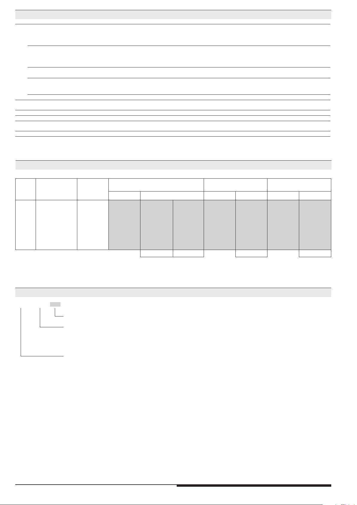
Technical Data
Relay type
OA/OW 5669
1.0 Relay coil
1.1 Nominal voltage DC V 6, 12, 20, 24, 48, 60, 110 (other on request)
1.2 Nominal consumption W 0.7
1.11 Voltage range U
1.3 Holding power (at 0.5 x U
) W 0.18
N
N
0.8 ... 1.6
2.0 Contacts
2.1 Contact arrangement 1 NC / 1NO
2 changeover contacts, 1 NO and 1 changeover contact
2.2 Contact material AgSnO
2.3 Rated insulation voltage AC V 250
+ 0.2 µm Au; AgNi + 0.2 µm Au, AgNi + 5 µm Au
2
Switching voltage min./max. V AC/DC 10 / DC 250, AC 400 (AC/DC 100 mV / 60 V)
2.4 Limiting continuous current I
th
Switching current min./max. A 10 mA
2.5 Switching power min./max. VA 3 / 2 000 (1 mVA / 7 VA)
Switching power min./max. W 3 / 200 (1 mW / 7 W)
2.6 Switching capacity
to IEC/EN 60947-5-1 AC 15
to IEC/EN 60947-5-1 AC 15
to IEC/EN 60947-5-1 DC 13
at 0.1 Hz DC 13
to UL 508
2.7 Electrical life
2)
4)
5)
4)
4)
AC 230 V 6 A cos ϕ = 1 switching cycles > 1 x 10
A 2 x 5 (see operating voltage limit curve)
AC V/A
AC V/A
DC V/A
DC V/A
3)
/ 8 (1 mA / 0.3 A)
1)
(see limit curve for arc-free operation)
NO: 250 / 2 NC: 250 / 1
NO: 250 / 3 NC: 250 / 2
NO: 24 / 2 NC: 24 / 1
NO: 24 / 4 NC: 24 / 4
R300
at 1 s On, 1 s Off (see contacts service life)
5
AgNi > 2 x 10⁵ AgSnO
1)
1)
2
2.8 Switching frequency max. switching cycles / s 10
2.9 Response time / Release time ms ≤ 15 / ≤ 12
2.10 Contact force cN ≥ 10 / ≥ 8
1)
3.0 Other
3.1 Mechanical life switching cycles ≥ 50 x 10
6
3.2 Temperature range °C - 40 ... + 70 mounted without distance (Ith = 2 x 5 A)
3.3 Degree of protection Solder line proof RT II as option wash proof RT III
3.5 Vibration resistance 10 ... 200 Hz; NC 2 g; NO 10 g; IEC/EN 60068-2-6
3.6 Climate resistance 40 / 060 / 04 (Klimakategorie); A/B/D IEC/EN 60068-1
3.7 Short circuit strength 1 kA / AC 250 V
1)
Values for AgNi-contacts + 5 µm Au
4)
Values for AgNi-contacts
All technical data in this list relate to the state at the moment of edition.
We reserve the right for technical improvements and changes at any time.
2)
5)
AgSnO
2
AgNi
10 A total current at t = 20°C and coil voltage UN
Values for AgSnO2-contacts
1
10 A gL EN 60947-5-1
6 A gL EN 60947-5-1
3)
Typical values
OA/OW 5669 / 14.04.14 en / 430
Page 2
Technical Data
3.8 Insulation acc. to IEC 60664-1, EN 50178
double and reinforced insulation
Rated insulation voltage AC V 250
Contamination level 2
Overvoltage category III
Test voltage
Contact-coil (1 min) AC kV eff. ≥ 4
Contact-contact (1min) AC kV eff. ≥ 4
Open contact acc. to DIN EN 61810-1 AC kV eff. 1.5
Transient voltage
Contact-coil (1.2 - 50 µs) kV ≥ 6
Clearance and creepage distances
Contact-coil mm ≥ 8
Contact-contact mm ≥ 5.5
3.9 Weight g approx. 19
4.0 Packing
4.1 on cardboard in slipcase piece 56
4.2 in case package piece 280
5.0 Solder method
5.1 Solder method /-temperature /-duration °C / s Wafe soldering / 260 / 5
Design versions
U
DC
V
N
Voltage
range
V
Resistance
Ω
(± 10%)
OA5669.12 OA5669.16 OA5669.12 OA5669.16 OA5669.12 OA5669.16
AgNi - contacts
+ 0.2 µm Au
AgNi - contacts
+ 5 µm Au
AgSnO
+ 0.2 µm Au
- contacts
2
6 4.8 ... 9.6 50 981 992 462 691 771 581
12 9.6 ... 19.2 210 982 993 463 692 772 582 553
20 16.0 ... 32.0 580 987 998 468 697 777 587 558
24 19.2 ... 38.4 820 983 994 464 693 773 583 554
48 38.4 ... 76.8 3200 984 995 465 694 774 584 555
60 48.0 ... 96.0 5200 985 996 466 695 775 585 556
110 88.0 ... 176.0 18000 986 997 467 696 776 586 557
1) 2) 1) 1)
1) = Pin configuration standard
2) = Pin configuration reverse
Ordering example
O_ 5669._ _ / _ _ _ / 61*
)
Design version
Pin configuration
.16 1 NC / 1 NO
.12 2 changeover contacts
.20 1 NO /1changeover ontact
Degree of protection
A = Solder line proof RT II
W = Wash proof RT III
)
*
/61 cURus approval
2
OA/OW 5669 / 14.04.14 en / 430
Page 3
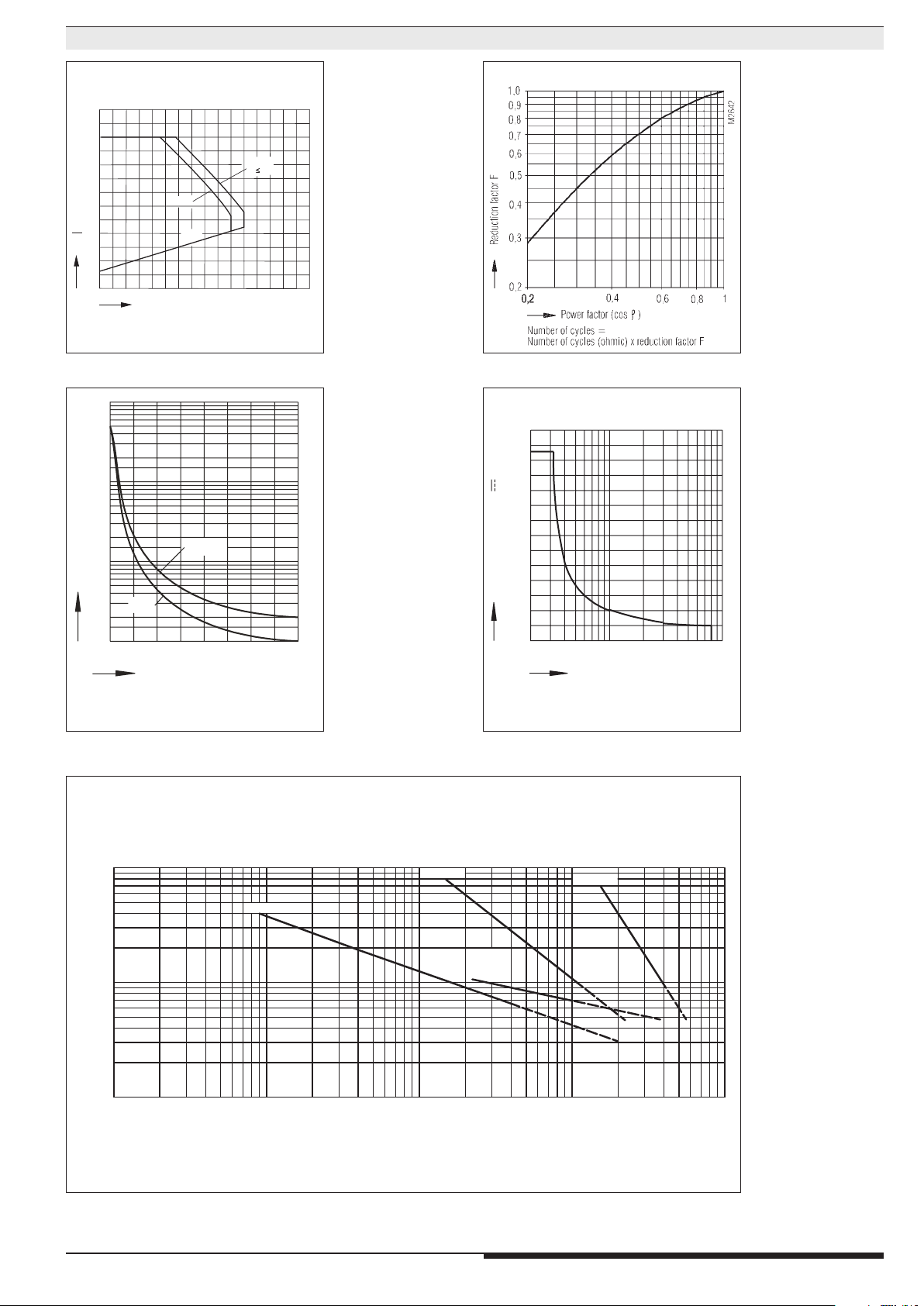
Characteristics
M2869_c
1,8
U
U
Ambient temperature
M2870_c
Switching cycles
Switching capacityP[kVA ]
0
0,2 0,4
0,6
0,8
1,0 1,2 1,4
1,6
10
10
10
10
8
7
6
5
6
4
2
2
4
6
2
4
6
AgNi
AgSnO
2
arc max. 1 switching cycle/s
M2871
Electrical life of the output contactsdeterminedby
OperationCycles
1,7
1,6
1,5
1,4
1,3
1,2
1,1
1,0
B
0,9
N
0,8
0,7
0,6
0,5
-20
-40
I = 8A
K
U min.
B
0
40
20
U max.
B
I2A
K
80
60
100
120°C
Operating voltage limit curve Reduction factor for reactive loads
260
220
Contact service life (at tu = 20°C) Limit curve for arc-free operation (at tu = 20°C)
DIN EN 60947-5-1 / Annex C.3
100
A
,1
0
x
t
n
rre
u
C
g
10
tin
ra
e
p
O
l
a
in
m
o
N
1
3
10
AC1:230V
DC13:24V
AC15:230V
45
10
10 10
Electrical life
180
140
100
Switching voltage U [ V ]
60
20
0
0,2
safe switch-off,no standing arc
3
0,7
0,4
2
Switching current I [A]
Contact material AgNi
DC1:24V
6
6
4
M4554_b
8
10
7
10
OA/OW 5669 / 14.04.14 en / 430
Page 4
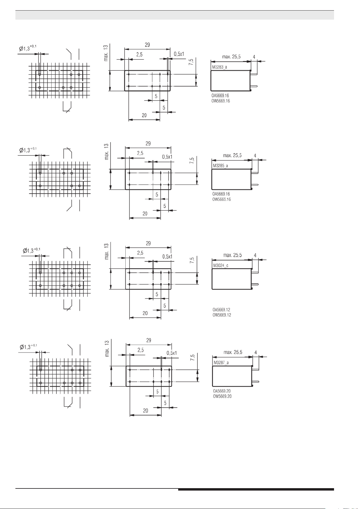
Dimensions, Pin Configuration, Connection Diagrams
Pin configuration standard
Drilling plan (solder side)
/9_ _
/9_ _
Pin configuration reverse
/4_ _
/4_ _
Connection for basic grid divensions 2.5 mm as well as 2.54 mm according to IEC/EN 60097 and IEC 60326 average
4
OA/OW 5669 / 14.04.14 en / 430
Page 5
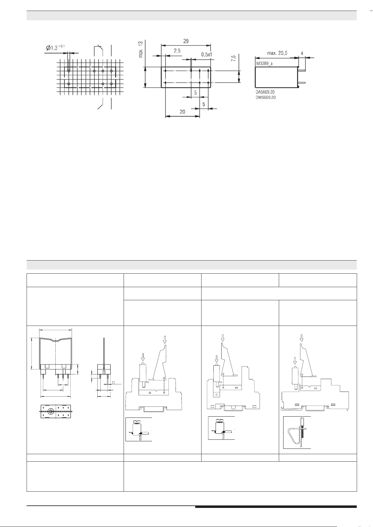
Dimensions, Pin Configuration, Connection Diagrams
34
32
0,5
M
3
5
9
0
_
a
M3795_a
M3795_a
M
3
5
8
9_
a
M3796_a
M
3
5
8
8
_
a
Connection for basic grid divensions 2.5 mm as well as 2.54 mm according to IEC/EN 60097 and IEC 60326 average
Drilling plan (solder side)
Accessories
Socket ET 1415.021
Fixing clip ET 1415.025
M2569_a
20,1
max. 31,5
Socket ET 1415.041 Socket ET 1415.044 Socket ET 1415.047
• Socket for DIN-rail
• incl. fixing clip
• Socket for DIN-rail
• incl. fixing clip
• incl. safe separation between
coil and contacts according to
DIN EN 60947-1,
DIN EN 61140, DIN EN 60204
Fixing clip
Function
module
10
4
2x5
1x
7,5
max. 13
Socket
Screw terminals
Function
module
Fixing clip
Socket
Screw terminals
Fixing clip
Function
module
Socket
Cage clamp
terminals
Article number: 0034769 Article number: 0055571 Article number: 0059274 Article number: 0059270
Fixing clip (wire): 0034770
Fixing clip (plastic): 0047726
Function modules
ET1415.913: DC 24 V, with free-wheel diode and green LED Article number: 0056828
ET1415.911: DC 24 V, with free-wheel diode and red LED Article number: 0055909
ET1415.924: DC 60 V, with free-wheel diode and red LED Article number: 0062552
ET1415.912: AC/DC 24 V, with varistor and green LED Article number: 0055910
5
OA/OW 5669 / 14.04.14 en / 430
Page 6

E. DOLD & SÖHNE KG • D-78114 Furtwangen
e-mail: dold-relays
@dold.com • internet: http://www.dold.com
•
PO Box 1251 • Telephone (+49) 77 23 / 654-0 • Telefax (+49) 77 23 / 654-356
6
OA/OW 5669 / 14.04.14 en / 430
 Loading...