

PCB Relays
Safety relay
monostable
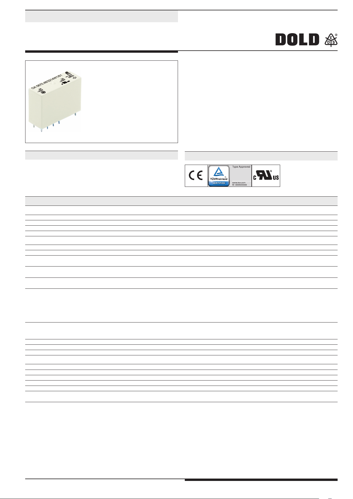
OA 5670
• Acc. to DIN EN 50205, DIN EN 61810-1, DIN EN 60664-1
• With forcibly guided contacts
• Double and reinforced insulation between contact sets
according to EN 50178
• High dielectric strength
• High mechanical service life
• High switching reliability
• Compact size
• High thermal continuous current
• High voltage range
Applications
Approvals and Marking
• Switchgear for safety technology
• Press controls
Canada / USA
Technical Data
Relais type
OA 5670
1.0 Relais coil
1.1 Nominal voltage DC V 6; 12; 20; 24; 48; 60; 110 (others on request)
1.2 Nominal consumption W 1.0
1.3 Holding power (at 0.5 x UN) W 0.25
2.0 Contacts
2.1 Contact arrangement 2 NO and 2 NC; 3 NO and 1 NC
2.2 Contact material AgSnO
2.3 Rated insulation voltage
Switching voltage min./max
2.4 Limiting continuous current I
Switching current min./max.
2.5 Switching power min./max.
Switching power min./max.
2.6 Switching capacity
to IEC/EN 60947-5-1 AC 15
to IEC/EN 60947-5-1 AC 15
to IEC/EN 60947-5-1 DC 13
at 0.1 Hz DC 13
th
4)
5)
4)
4)
AC V
V
A
A
VA
W
AC V/A
AC V/A
DC V/A
DC V/A
3 / 160 (1 mW / 7 W)1) (s. limit curve for arc-free operation)
to UL 508
2.7 Electrical life
at AC 230 V, 6 A, cosj = 1
at DC 24 V, 6 A ohmsch
2.8 Switching frequency max.
switching cycles
switching cycles
switching cycles
switching cycles
/s 10
+ 0.2 µm Au; AgNi + 0.2 µm Au, AgNi + 5 µm Au
2
250
AC/DC 10 / DC 250, AC 400 (AC/DC 100 mV / 60 V)
3 x 6 (see operating voltage limit curve)
10 mA3) / 6 (1 mA / 0.3 A)
3 / 1 500 (1 mVA / 7 VA)
1)
1)
NO: 250 / 2 NC: 250 / 1
NO: 250 / 3 NC: 250 / 1
NO: 24 / 1 NC: 24 / 1
NO: 24 / 4 NC: 24 / 3
B300 / R300
at 1 s On, 1 s Off (see contacts service life)
> 1.2 x 10
> 1.2 x 10
5
AgNi 10
5
AgNi 10
1)
2.9 Response time / Release time ms typically 11 / typically 6
2.10 Contact force NO / NC cN ≥ 10
3.0 Other
3.1 Mechanical life
switching cycles
≥ 50 x 10
6
3.2 Temperature range °C - 40 ... + 75
3.3 Degree of protection, housing Solder line proof RT II as option wash proof RT III
3.5 Vibration resistance 10 ... 200 Hz; NC 5 g; NO 10 g; IEC/EN 60068-2-6
3.6 Climate resistance 40 / 060 / 04 (climate category); A/B/D IEC/EN 60068-1
3.7 Short circuit strength 1 kA / AC 250 V
AgNi or
AgSnO
2
6 A gL EN 60947-5-1
1)
Values for AgNi-Contacts + 5 µm Au
4)
Values for AgNi-Contacts
All technical data in this list relate to the state at the moment of edition.
We reserve the right for technical improvements and changes at any time.
2)
5)
10 A total current at t = 20°C and coil voltage UN
Values for AgSnO2-Contacts
1
3)
Typical values
OA 5670 / 14.04.14 en / 430
Technical Data
3.8
Insulation acc. to IEC 60664-1, EN 50178
double and reinforced insulation
Rated insulation voltage AC V 250
Contamination level 3
Overvoltage category III
Test voltage
Contact-Coil (1 min) AC kV eff. ≥ 4
Left contact-right contact (1min) AC kV eff. ≥ 4
Contact-Coil (1min) AC kV eff. ≥ 3
Open contact acc. to DIN EN 61810-1 AC kV eff. 1.5
Transient voltage
Contact-Coil (1.2 - 50 µs) kV ≥ 6
Clearance and creepage distances
Contact-Coil mm ≥ 8
Left contact-right contact mm ≥ 5.5
Contact-Contact mm ≥ 4.5
3.9 Weight g approx. 21
4.0 Packing
4.1 on cardboard piece 42
4.2 in case package piece 210
5.0 Solder method
5.1 Solder method /-temperature /-duration °C / s Wafe soldering / 260 / 5
Design Versions
OA 5670
U
N
(DC V)
Voltage
range
(DC V)
Resistance
at 20°C
Ω ±10%
.52 .48
2NO, 2NC 3NOS, 1NC
AgNi10 + 0,2 µm Au-contacts
6 4.2 ... 8.4 36 3201 3211
12 8.4 ... 16.8 150 3202 3212
20 14.0 ... 28.0 400 3203 3213
24 16.8 ... 33.6 580 3204 3214
48 33.6 ... 67.2 2300 3205 3215
60 42.0 ... 84.0 3600 3206 3216
110 77.0 ... 154.0 12100 3207 3217
+ 0,2 µm Au-contacts
AgSnO
2
6 4.2 ... 8.4 36 3221 3231
12 8.4 ... 16.8 150 3222 3232
20 14.0 ... 28.0 400 3223 3233
24 16.8 ... 33.6 580 3224 3234
48 33.6 ... 67.2 2300 3225 3235
60 42.0 ... 84.0 3600 3226 3236
110 77.0 ... 154.0 12100 3227 3237
AgNi10 + 5 µm Au-contacts
6 4.2 ... 8.4 36 3241 3251
12 8.4 ... 16.8 150 3242 3252
20 14.0 ... 28.0 400 3243 3253
24 16.8 ... 33.6 580 3244 3254
48 33.6 ... 67.2 2300 3245 3255
60 42.0 ... 84.0 3600 3246 3256
110 77.0 ... 154.0 12100 3247 3257
Ordering Example
OA 5670 ._ _ / _ _ _ _ _ _ / 61*
)
Pin configuration
L = standard, solder line proof RT II
W = wash proof RT III
Design version
Contacts
.52 2 NO, 2 NC
.48 3 NO, 1 NC
Relay type
)
/61 cURus approval
*
2
OA 5670 / 14.04.14 en / 430

Characteristics
1,8
Ambient temperature
M2870_c
Switching cycles
8
Switchting voltage U [ V ]
Switching current I [A]
Safe switch off,no standing arc
max. 1 switching cycle/s
260
220
180
140
100
60
20
0
0,2
0,4
0,7
2
4
6
8
10
M2998
1,7
1,6
1,5
1,4
1,3
1,2
1,1
1,0
U
B
0,9
U
N
0,8
0,7
0,6
0,5
-20
-40
0
U max.
B
I=3x8A
K
20
U max.
B
I2A
K
U min.
B
40
60
M2997_c
80
100°C
Operating voltage limit curve Reduction factor for inductive loads
10
6
4
2
7
10
6
4
2
6
10
6
4
AgNi
2
5
10
0,2 0,4
0
AgSnO
2
0,8
0,6
1,0 1,2 1,4
Switching capacityP[kVA ]
1,6
Contact service life (at tu = 20°C) Limit curve for arc-free operation
= 20°C)
(at t
u
3
OA 5670 / 14.04.14 en / 430

Dimensions, Pin Configuration, Connection Diagrams
M
2
7
3
7
_
b
K4K2
K1
K3
1,3
+0,1
Ø
Drilling plan (solder side)
OA5670.52___L1 2NO/2NC
OA5670.48___L1 3NO/1NC
OA5670.48___L2 3NO/1NC
OA5670.52___L2 2NO/2NC
OA5670.52___L3 2NO/2NC
OA5670.52___L4 2NO2NC
Connection for basic grid divensions 2.5 mm as well as 2.54 mm according to IEC/EN 60097 and IEC 60326 average
4
OA 5670 / 14.04.14 en / 430

Accessories
13
3,7
15
5
37,7
Sockel ET 1415.034
M4546_b
,1
0
+
0
-
1,3
7,5
Article number: 0064297
0,5
8,4
3,9
23
5
OA 5670 / 14.04.14 en / 430

E. DOLD & SÖHNE KG • D-78114 Furtwangen
e-mail: dold-relays
@dold.com • internet: http://www.dold.com
•
Postfach 1251 • Telefon 0 77 23 / 654-0 • Telefax 0 77 23 / 654-356
6
OA 5670 / 14.04.14 en / 430
 Loading...