

Page 1
PCB relays
Safety relays
monostable
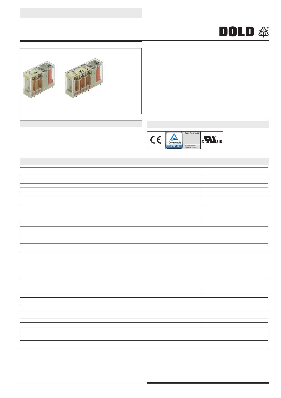
OA 5611, OA 5612
OA 5611 OA 5612
• Acc. to DIN EN 50205, DIN EN 61810-1, DIN EN 60664-1
• With forcibly guided contacts
• Low rated power consumption
• High mechanical service life
• High switching reliability due to crown contacts with
large relative movement
• Compact size
• Optionally wash proof
Applications
Approvals and Marking
• To be used in circuits for safety applications
• Escalators and walkways
• Elevators for men and load
• Railway technology
Canada / USA
Technical Data
Relay type
OA 5611 OA 5612
1.0 Relay coil
1.1 Nominal voltage DC V 6, 12, 24, 48, 60, 110 (others on request)
1.2 Nominal consumption W 0.6 0.8 / 1.0
1.11 Voltage range U
1.13 Holding power (at 0.5 x U
) W 0.15 0.20 / 0.24
N
N
0.7 ... 1.4
2.0 Contacts
2.1 Contact arrangement 2 NO / 2 NC
3 NO / 1 NC
2 NO / 4 NC
3 NO / 3 NC
4 NO / 2 NC
5 NO / 1 NC
2.2 Contact material AgSnO
2.3 Rated insulation voltage AC V 250
+ 0.2 µm Au; AgNi + 0.2 µm Au, AgNi + 5 µm Au
2
Switching voltage min./max V AC/DC 10 / DC 250, AC 400 (AC/DC 100 mV / 60 V)
2.4 Limit. contin. current I
Switching current min./max A > 10 mA
2.5 Switching power min./max. VA 3 / 2000 (1 mVA / 7 VA)
Switching power min./max W 0.14) / 200 (1 mW / 7 W)
2.6 Switching capacity
to IEC/EN 60947-5-1 AC 15
to IEC/EN 60947-5-1 AC 15
to IEC/EN 60947-5-1 DC 13
at 0.1 Hz DC 13
to UL 508
2.7 Electrical life at 1 s ON, 1 s OFF (see contacts service life)
at AC 230 V, 5 A, cosj = 1
at AC 230 V, 8 A, cosj = 1
max. A 3 e.g. 5 x 8 (see operating voltage limit curve)
th
5)
6)
5)
5)
AC V/A
AC V/A
DC V/A
DC V/A
4)
/ 8 (1 mA / 0.3 A)
1)
(see limit curve for arc-free operation)
1)
1)
NO: 250 / 2 NC: 250 / 1
NO: 250 / 3 NC: 250 / 2
NO: 24 / 1 NC: 24 / 1
NO: 24 / 4 NC: 24 / 4
B300
5
switching cycles
switching cycles
> 3 x 10
> 1.5 x 10
AgSnO
5
AgSnO
2
2
> 2 x 10
> 10
5
5
AgNi 10
2.8 Switching frequency max. switching cycles / s 10
2.9 Response time / Release time ms typically 20 / typically 6
2.10 Contact force cN ≥ 10
2.14 Contact gap mm > 1 (normal operation) / > 0.5
2)
(under fault)
3)
3)
1)
AgNi 10
3.0 Other
3.1 Mechanical life switching cycles ≥ 50 x 10
6
3.2 Temperature range °C - 40 ... + 85 - 40 ... + 85
3.3 Degree of protection Solder line proof RT II as option wash proof RT III
3.5 Vibration resistance 10 ... 200 Hz; 0.35 mm amplitude; 3 g max. IEC/EN 60068-2-6
3.6 Climate resistance Humid heat IEC/EN 60068-2-30
3.7 Short circuit strength 1 kA / AC 250 V
1)
All technical data in this list relate to the state at the moment of edition.
We reserve the right for technical improvements and changes at any time.
Values for AgNi 10-Contacts + 5 µm Au
3)
OA 5612.50 (2 NO / 4 NC)
5)
Values for AgNi-Contacts
4)
6)
AgSnO
2
AgNi
2)
over entire service life,even when under fault and at 1.4 x U
Typical values
Values for AgSnO
1
NO: 10 A gL / NC: 10 A gL EN 60947-5-1
NO: 10 A gL / NC: 6 A gL EN 60947-5-1
-
Contacts
2
N
OA 5611, OA 5612 / 14.04.14 en / 430
Page 2
Technical Data
3.8 Insulation acc. to IEC 60664-1, EN 50178
Rated insulation voltage AC V 250
pollution degree 3
Overvoltage category III
Test voltage
Contact - Coil (1 min) AC kV eff. ≥ 4
Contact - Contact (1min) AC kV eff. ≥ 2.5
Open contact acc. to DIN EN 61810-1 AC kV eff. 1.5
Transient voltage
Contact - Coil (1,2 - 50 µs) kV ≥ 6
Clearance and creepage distances
Contact - Coil mm ≥ 8
Contact side-Contact side mm ≥ 4.5
Contact - Contact mm ≥ 4.5
3.9 Weight g approx. 35 approx. 38
4.0 Packing
4.1 on cardboard piece 30 20
4.2 in case package piece 150 100
5.0 Solder method
5.1 Solder method /-temperature /-duration °C / s Wafe soldering / 260 / 5
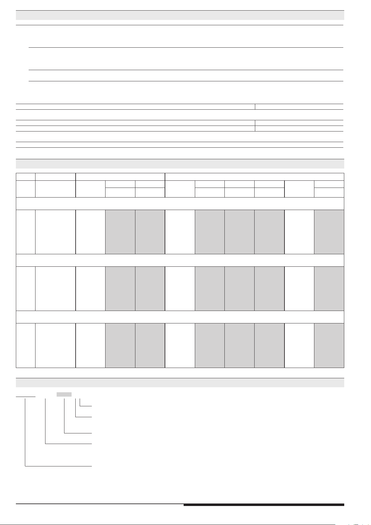
Design versions
OA 5611 OA 5612
U
N
(DC V)
Voltage
range (DC V)
R
Coil
Ω ± 10%
.48 .52
3NO, 1NC 2NO, 2NC 3NO, 3NC 4NO, 2NC 5NO, 1NC 2NO, 4NC
R
Coil
Ω ± 10%
.18 .54 .60
R
Coil
Ω ± 10%
.50
AgSnO-contacts + 0,2 µm Au
6 4,2 ... 8,4 56 2491 2521 45 2401 2461 2571 36 2431
12 8,4 ... 16,8 240 2492 2522 180 2402 2462 2572 145 2432
24 16,8 ... 33,6 960 2493 2523 720 2403 2463 2573 600 2433
48 33,6 ... 67,2 3840 2494 2524 2880 2404 2464 2574 2300 2434
60 42,0 ... 84,0 6000 2495 2525 4500 2405 2465 2575 3600 2435
110 77,0 ... 154,0 20150 2496 2526 15125 2406 2466 2576 12100 2436
AgNi-contacts + 0,2 µm Au
6 4,2 ... 8,4 56 2501 2531 45 2411 2471 2581 36 2441
12 8,4 ... 16,8 240 2502 2532 180 2412 2472 2582 145 2442
24 16,8 ... 33,6 960 2503 2533 720 2413 2473 2583 600 2443
48 33,6 ... 67,2 3840 2504 2534 2880 2414 2474 2584 2300 2444
60 42,0 ... 84,0 6000 2505 2535 4500 2415 2475 2585 3600 2445
110 77,0 ... 154,0 20150 2506 2536 15125 2416 2476 2586 12100 2446
AgNi-contacts + 5 µm Au
6 4,2 ... 8,4 56 2511 2541 45 2421 2481 2591 36 2451
12 8,4 ... 16,8 240 2512 2542 180 2422 2482 2592 145 2452
24 16,8 ... 33,6 960 2513 2543 720 2423 2483 2593 600 2453
48 33,6 ... 67,2 3840 2514 2544 2880 2424 2484 2594 2300 2454
60 42,0 ... 84,0 6000 2515 2545 4500 2425 2485 2595 3600 2455
110 77,0 ... 154,0 20150 2516 2546 15125 2426 2486 2596 12100 2456
Ordering example
OA 5611 ._ _ /_ _ _ _ _ _ / 61*
)
Pin configuration
L = solder line proof RT II
W = wash proof RT III
Design version
Contact arrangement
.48 3 NO, 1 NC
.52 2 NO, 2 NC
Relay type
*) / 61 cURus approval
2
OA 5611, OA 5612 / 14.04.14 en / 430
Page 3

Characteristics
M2683_b
1,8
Ambient temperature
M2868_b
1,8
U
U
]
7
[A]
78
M5834_a
N
o
m
in
a
l
O
p
e
r
a
tin
g
C
u
r
r
e
n
t
x
0
,1
A
10
7
5
10
Switching cycles
10
3
2
6
7
5
3
Ag Ni10
2
5
0,5 1,0 1,5 2,0
1,7
1,6
1,5
1,4
1,3
1,2
1,1
1,0
U
B
0,9
U
N
0,8
0,7
0,6
0,5
-20
-40
0
20
Ambient temperature
I = 3x8A
K
U min.
B
I = 3x6A
K
40
U max.
B
I2A
K
80
60
100
120°C
1,7
1,6
1,5
1,4
1,3
1,2
1,1
1,0
B
0,9
N
0,8
0,7
0,6
0,5
-40
I = 5x8A
I = 5x6A
K
K
U max.
B
I2A
K
U min.
B
0
-20
40
20
80
60
100
120°C
Switching capacity P[kVA
Operating voltage limit curve OA 5611 Operating voltage limit curve OA 5612 Contact service life
250
M2983_b
AgSnO
2
200
150
100
switching voltage U [ VDC ]
50
0
12 34
56
switchingcurrentI
safe breaking,nocontinuous arcing,
max.1switching cycle/s
Contact service life Reduction factor for inductive loads Limit curve for arc-free operation
(load limit curve)
Electrical life of the output contacts determined by
DINEN 60947-5-1/AnnexC.3
100
DC1:24V
AC15:230V
DC13:24V
AC1:230V
M4234_a
10
1
45
10
10 10
6
10
7
Operation Cycles
Electrical life
3
OA 5611, OA 5612 / 14.04.14 en / 430
Page 4

OA 5611 Dimensions, Pin Configuration, Connection Diagrams
M
2
0
3
2
_
e
I
I
I
I
I
I
I
I
I
I
I
I
I
I
I
I
I
I
1
0
2,6
20
41,9
0,5x1
5
3x5
30,5
M2030_e
Drilling plan (solder side)
0,5
3,1
,5
4
1
Pin arrangements OA 5611.52/...L1 2NO / 2NC Pin arrangements OA 5611.52/...L4 2NO / 2NC
1
,
3
+
-
0
0
,
1
Pin arrangements OA 5611.52/...L5 2NO / 2NC
1
,
3
+
-
0
0
,
1
c
_
8
6
4
3
M
1
1
23
23
4
4
1
,
3
+
-
0
0
,
1
d
_
2
6
4
3
M
Pin arrangements OA 5611.48/...L1 3NO / 1NC
1
,
3
+
-
0
0
,
1
e
_
1
3
0
2
M
1
1
23
23
4
4
Pin arrangements OA 5611.48/...L4 3NO / 1NC Pin arrangements OA 5611.28 1NO / 3NC
1
,
3
+
-
0
0
,
1
c
_
4
6
4
3
M
1
Connection for basic grid divensions 2.5 mm as well as 2.54 mm according to IEC/EN 60097 and IEC 60326 average
23
4
1
,
3
+
-
0
0
,
1
d
_
5
3
4
3
M
4
1
23
4
OA 5611, OA 5612 / 14.04.14 en / 430
Page 5

OA 5612 Dimensions, Pin Configuration, Connection Diagrams
I
I
I
I
I
I
M
3
4
7
1
_
d
I
I
I
M
2
0
4
0
_
e
I
I
I
I
I
I
I
I
I
I
I
I
1
0
2,6
51,5
0,5x1
5
20
Drilling plan (solder side)
5x5
M2037_d
30,5
0,5
,5
4
1
3,1
Drilling plan (solder side)
Pin arrangements OA 5612.60/...L4 5NO / 1NC
1
,
3
+
-
0
0
,
1
d
_
9
6
4
3
M
1
23
4
5
6
Pin arrangements OA 5612.60/...L1 5NO / 1NC
1
,3
+
-
0
0
,
1
e
_
4
0
6
2
M
Pin arrangements OA 5612.54/...L1 4NO / 2NC
1
,
3
+
-
0
0
,
1
1
1
23
23
4
5
6
4
5
6
Pin arrangements OA 5612.54/...L4 4NO / 2NC
1
,
3
+
-
0
0
,
1
Pin arrangements OA 5612.50/...L4 2NO / 4NC
1
,
3
+
-
0
0
,
1
d
_
5
7
4
3
M
1
1
23
23
4
5
6
4
5
6
Pin arrangements OA 5612.50/...L1 2NO / 4NC Pin arrangements OA 5612.18/...L1 3NO / 3NC
1
,
3
+
-
0
,
0
1
e
_
9
3
0
2
M
Connection for basic grid divensions 2.5 mm as well as 2.54 mm according to IEC/EN 60097 and IEC 60326 average
1
23
4
5
6
1,
3
+
-
0
0
,
1
e
_
8
3
0
2
M
5
1
23
4
5
6
OA 5611, OA 5612 / 14.04.14 en / 430
Page 6

Accessories
20
5
4,2
4,2
Socket ET 1415.031
14,6
10
Article number: 0049512
Socket ET 1415.032
14,6
44,3
8,4
18,4
M2380_c
M2381_d
1
,
0
0
-
+
1,3
3,8
0,1
0
-
+
1,3
5
20
10
Article number: 0049513
54,4
8,4
3,8
18,4
E. DOLD & SÖHNE KG • D-78114 Furtwangen
e-mail: dold-relays
@dold.com • internet: http://www.dold.com
•
PO Box 1251 • Telephone (+49) 77 23 / 654-0 • Telefax (+49) 77 23 / 654-356
6
OA 5611, OA 5612 / 14.04.14 en / 430
 Loading...