

Page 1
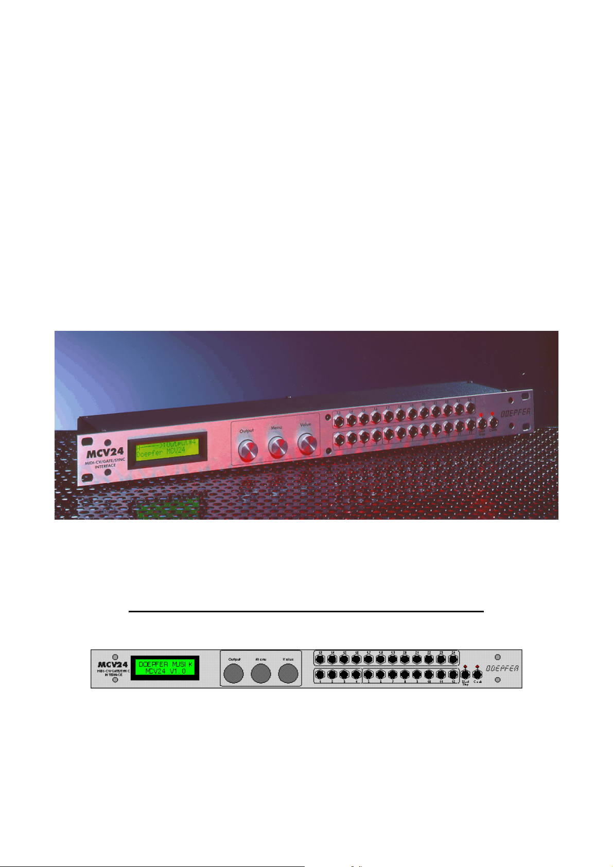
DOEPFER
MCV24
MIDI-CV/GA TE/SYNC INTERF ACE
Pr eliminary English owners manual
written by EMIS (C) 1999 Revision 1.0 July 1999
Page 2
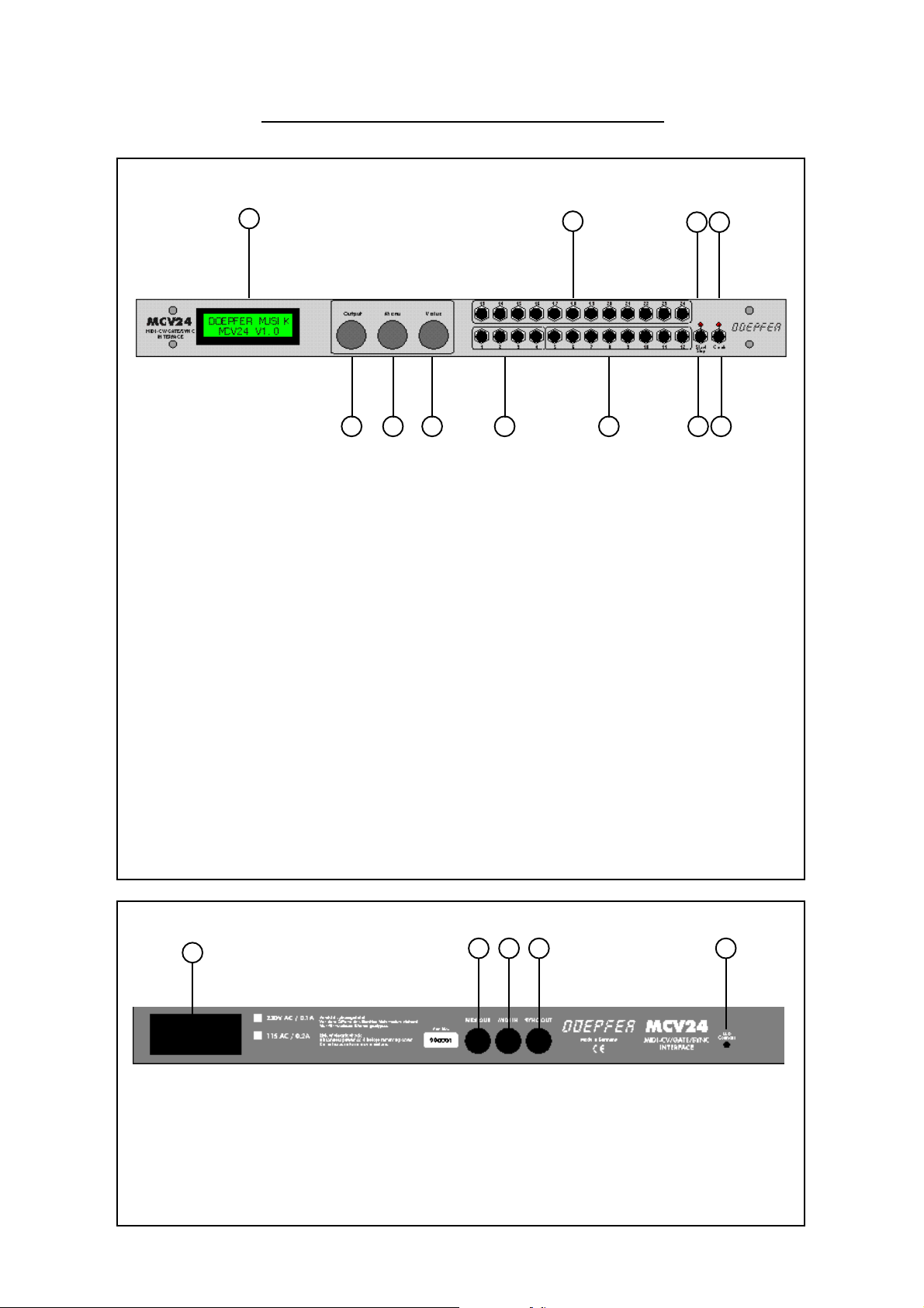
Frontpanel
Controls and connections
1
5 6 7 8 9
1 32 character backlit LCD screen.
2 12 outputs using an 8-bit DAC optimised for 0~10V output
3 Start/Stop LED indicator controlled by MIDI input. (linked to pin 1 of Sync socket)
4 Clock LED indicator controlled by MIDI clock. (linked to pin 3 of Sync socket)
Dual function controls - Rotary and Push
5 {Rotary} - Output select - selects one of the 24 outputs for programming
{Push} - Enters the value selected with rotary selection
6 {Rotary} - Menu select - selects which page of parameters to edit
{Push} - Enters the selected parameter for use selected with rotary selection
7 {Rotary} - V alue select - selects a value for the current parameter
{Push} - Enters the value selected by the rotary control for useage
2
3 4
10 11
8 4 outputs using a 12-bit DAC optimised for -2~8V at one volt per octave scaling
9 8 outputs using an 8-bit DAC optimised for 0~10v at one volt per octave scaling
10 Start/Stop output. (linked to pin 1 of Sync socket)
11 Clock output (linked to pin 3 of Sync socket)
Back panel
16
12 MIDI out is also the thru of the MIDI input
13 MIDI input
14 Sync output with programmable divide ratio of MIDI clock
15 LCD Contrast - adjusts the viewing angle for the LCD
16 Power switch
12 13 14 15
Page 3

MCV24 Overview
The MCV24 is a flexible MIDI to analogue interface, and any of it’s 24 outputs can be configured for
any purpose such as control voltages for VCO pitch, control voltages for any modulation destination (such as
VCF or VCA), triggers or gates. Outputs 1 to 4 are higher precision 12-bit DAC’s, whilst the rest are 8-bit
DAC’s, outputs 1 to 12 are optimised for one volt per octave scaling, but can also be set to Hertz/volt scaling
(like most Korg and Y amaha instruments). All outputs have a programmable slew control to reduce digital
quantisation inherent in a 7-bit MIDI system, in fact this slew control on the analogue side can produce a
smoother control voltage from an 8-bit converter than some 16-bit converters manage without the slew
control.
Each CV output has programmable offset and range along with a secondary CV that is mixed with the
first one, and can be any MIDI event or controller.
24 software driven voltage controlled LFO’ s each with selectable waveforms, waveshapes (including
random), MIDI syncable, output offset and rate control - one for each of the available outputs
24 software driven voltage controlled ADSR envelopes - one for each of the available outputs
24 software driven voltage controlled slew limiters for portamento or filtering quantisation.
Modulation matrix allows up to 6 patches per output, modulation of any source to any destination
Independent keying modes for each output including high note, low note, last note and poly modes
All outputs can be set for volt per octave or hertz per volt scaling
Calibration of all tuning and scaling done from the front panel - no trimmer presets to adjust
Programmable clock division from MIDI clock, plus clock inversion option
16 non-volatile memories (remembers when switched off), to suit varying system requirements.
Programmable memories can be named
Start/Stop output on front panel converts MIDI transport
5-pin DIN sync socket output on rear panel, can be programmed to any standard such as Roland (24)
, Korg (48), Linn (96) etc..
Page 4

MCV24 Basics
The MCV24 doesn’t really have any controls for operation, once it has been programmed to do a
particular function, that is exactly what it does, so once programmed, changing presets is probably the only
operation required on the MCV24. However, a full understanding of what the MCV24 will do and how to set
it up is a vital element that must be learned first. As the requirement of a MIDI to CV interface is likely to be
different for everyone, it is difficult to generate “factory” presets, as the instruments to which it is going to be
used with is an unknown factor . Assuming it is most likely to be a Doepfer A-100 system is fine, except it
would still be unknown what kind of control is needed. So, unlike most pieces of equipment, we have to start
learning the MCV24 by programming, rather than calling up a few factory presets to experiment with.
If you absolutely must try to make the MCV24 work straight away , try connecting the CV1 output to
a VCO input, and CV13 output to the Gate input, and transmit your MIDI input on channel 1, but when you
need to know why - read on.
Controls
Perhaps the first control to mention is the LCD contrast control on the rear panel, this should only need
to be set once, and if needed to be altered a small screwdriver is needed, as the control is recessed behind the
back panel. In most cases, it will be unnecessary to adjust this control anyway .
The front panel has 3 controls OUTPUT , MENU and V ALUE, although these are actually dual controls
as they have a press action as well to select the item selected by them. The MENU controls which parameter
to edit, the VALUE knob is used to change the value (pressing the knob actually enters the data), and the
OUTPUT knob selects which of the 24 outputs to be edited.
In most examples shown here, Output 01 is used and shown, but the operations relate to all 24 outputs.
Page 5
MENUS
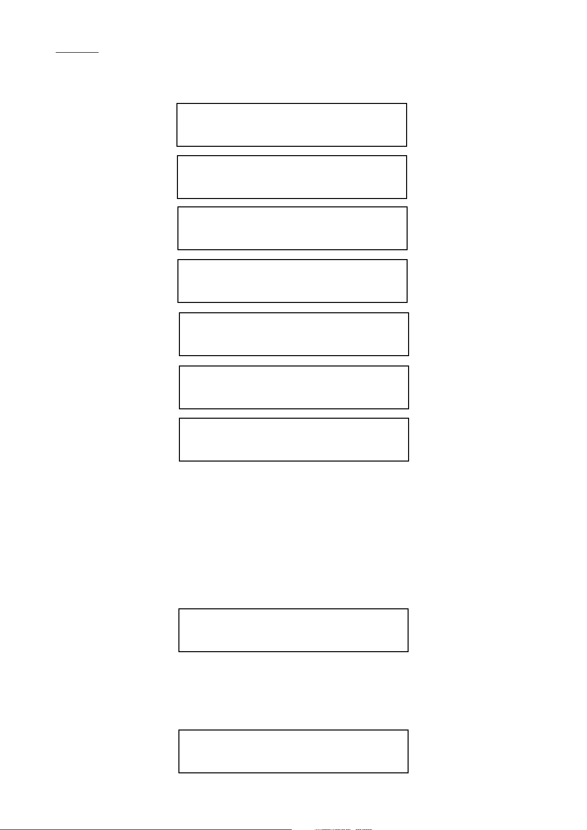
There are 7 pages of operation within the menu, labelled A to G.
A----->:Output01
Doepfer MCV24
<B---->:Output01
CV Parameter
<-C--->:Output01
LFO & ADSR Param
<--D-->:Output01
ModulationMatriX
<---E->:Output01
System Parameter
<----F>:Output01
Global Sync Par.
<-----G:Output01
Preset&Utilities
Turning the MENU control moves between the pages. T urn the MENU knob anticlockwise until the
screen below is shown. (If you are into a deeper menu, you will need to press the MENU knob to return to
this page.
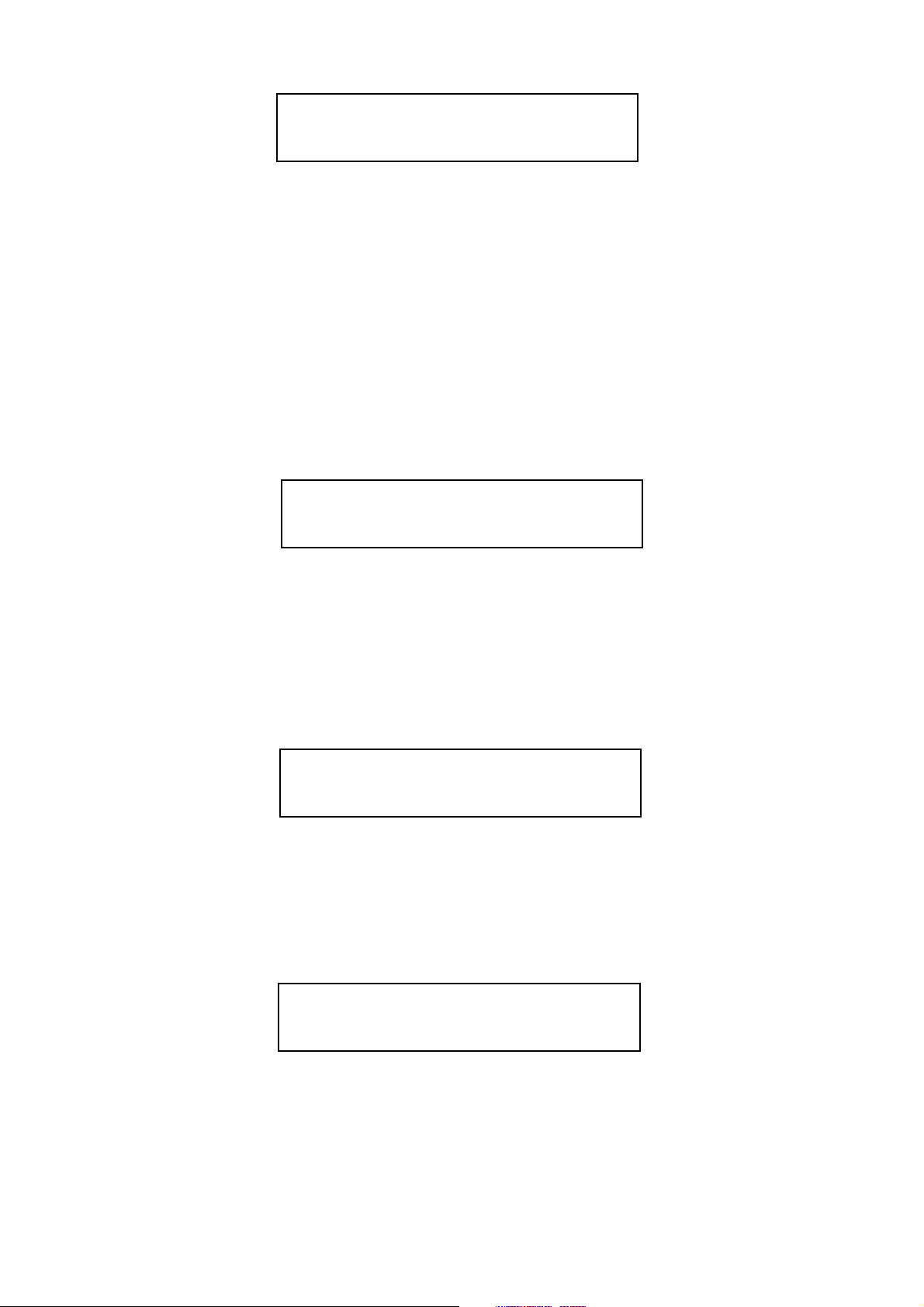
MENU-A
A----->:Output01
Doepfer MCV24
The first page is actually just an information page, and reminds you that you have a Doepfer MCV24,
however, if you press the MENU knob, the installed operating system version and release date is displayed.
V1.0 15.06.99
(c) Doepfer GmbH
Page 6
MENU-B
<B---->:Output01
CV Parameter
There are two CV’s per output which are mixed together , CV1 and CV2 have different options available
with some cross over, though CV1 is the only one that can be assigned notes, and CV2 is the only one that
can be assigned pitch bender for example.
CV P ARAMETER
The CV Parameter menu holds many pages, as this section is where most of the settings live. Pressing
the MENU knob enters the first page (actually , the page you go to is the last page before this menu was
exited, so in here, turn the knob anticlockwise until the screen as shown below is on the screen).
MIDI TO
EditCV1:Output01
Midito:xxxxxxxxx
The MIDI T o function selects which MIDI event will be assigned to control the selected output (Output
01 in the case of the example shown here). Depending on which event is selected, determines how many edit
pages are available, as all unrelated options are suppressed to keep things clearer .
The MIDI sources available for CV1 are: Off, Notes, Controllers, Poly Aftertouch and Mono Aftertouch.
MIDI TO - NO EVENT
EditCV1:Output01
Midito:NoEvent>>
No Event is basically the OFF option, this only turns off CV1, CV2 is still active. There are then no
pages to select that relate to CV1.
MIDI TO - NOTE EVENT
EditCV1:Output01
Midito:NoteEvent
Note Event selects MIDI notes to be used for CV1 output. 5 additional pages of options become
available relating to notes.
Page 7
MIDI CHANNEL
EditCV1:Output01
Midichannel:001
The MIDI CHANNEL pages allows the MIDI channel to be assigned to control a particular output
CV. Any channel between 1 and 16 can be selected here. In the example shown, output CV number 1 is
being controlled by MIDI channel 1.
MODE
EditCV1:Output01
Mode:xxxxxxxx
Mode is the keying priority for the selected output, the options are:-
High Note When played legato or polyphonically , the highest (top) note will be used
High & Follow Same as High Note mode, except the highest note will retrigger when played legato
or polyphonically if a higher note is released with another note held down.
Low Note If played legato or polyphonically, the lowest (bottom) note will be used
Low & Follow Same as Low Note mode, except the lowest note will retrigger when played legato
or polyphonically if a lower note is released with another note held down.
Last Note However played, whatever the last note played, will be used
---------- Reserved for future expansion
Poly 1 Allows multiple CV outputs to be set to the same MIDI channel and played
polyphonically.
Poly 1 & Priority As Poly 1 except priority given to note
Poly 2 Same as Poly 1, except with a different key reassignment system.
Poly 2 & Priority same as Poly 2, except priority given to note.
BASE NOTE
EditCV1:Output01
BaseNote :c1
The Base Note is the lowest note that can be played from the keyboard. This is actually setting the note
that is assigned to a CV output of 0V . Ideally , this is the lowest C on the controlling keyboard, any other note
will transpose the CV output. Note the use of German musical terminology, where B is shown as H, the upper
case letters are negative values (C1 for example is C-1), and with no number, indicates the normal bottom
note of a 5 octave keyboard (C = C0 which is MIDI note 36 - the note that a General MIDI Drum kit Bass
Drum is on). Because it is the base note that is being changed, it may appear that the value knob increments
the pitch the wrong way - as you turn the control clockwise and the base note goes up - the pitch falls. This is
correct and just about logical if you give it some thought - which we will not go into here.
Page 8
NOTE FROM
EditCV1:Output01
From:C3
This setting can be a bit difficult to grasp, yet simple when understood. This setting of FROM and the
next setting of TO, allows a keyboard zone to be specified, essential a low note (From) and a high note (T o)
that the output CV will work within. Most of the time, this will be set across the entire keyboard, with a
FROM setting of C3 (value = 000) and a TO setting of g6 (value = 127). So to define a five octave keyboard
range FROM is set to C and TO is set to c4, although there is rarely any need to restrict the range, so leaving
the default setting of FROM C3 and TO g6 is advisable.
NOTE TO
EditCV1:Output01
to :g6
The upper note setting for the above Note FROM setting. If you set the TO lower than the FROM,
then this has the same effect as an off position, and no data will be passed.
The next setting is SLEW , but before this, we will take a look at the different settings for dif ferent
settings of MIDI TO.
MIDI TO - CONTROLLERS
EditCV1:Output01
Midito:Controll.
Midi T o Controller defines the MIDI control to a MIDI controller or a range of controllers, which is set
with the following menu items.
MIDI CHANNEL
EditCV1:Output01
Midichannel:001
The MIDI CHANNEL pages allows the MIDI channel to be assigned to control a particular output
CV. Any channel between 1 and 16 can be selected here. In the example shown, output CV number 1 is
being controlled by MIDI channel 1.
Page 9

FROM
EditCV1:Output01
From:Modulation
The FROM and TO (next item) parameters select which controller to use. It is possible by using the
FROM and TO range to specify just one controller number (perhaps this is the normal mode anyway), or a
range can be specified - this could allow several controllers to control the same destination, such as Mod
wheel (controller 1) and breath controller (Controller 2).
Where a reserved function is assigned to a MIDI controller, the display will show that function by name
rather than number, such as controller 1 is the Modulation wheel and controller 7 is Channel Volume.
TO
EditCV1:Output01
To :Breath Ctrl
This is the TO part of the controller range setting. If you set the TO lower than the FROM, then this has
the same effect as an off position, and no data will be passed.
The next setting is SLEW , but before this, we will take a look at more different settings for dif ferent
settings of MIDI TO.
MIDI TO
EditCV1:Output01
Midito:PolyAfter
Midi T o poly aftertouch defines the MIDI control to polyphonic aftertouch.
MIDI CHANNEL, MODE, BASE NOTE, FROM, TO
These settings are the same as that for MIDI EVENT=Notes, please refer to this section at the beginning
of this section.
MIDI TO
EditCV1:Output01
Midito:MonoAfter
This selects MIDI to monophonic aftertouch, which is the aftertouch data generated by most keyboards.
There are no additional parameters with mono aftertouch, so we move on to where all the other menus pages
turn to next:- Slew
Page 10

SLEW
EditCV1:Output01
Slew :On >>
This is where the Slew function is enabled or disabled. When on, the CV output voltage is slewed,
which means it’s rate of change is slightly lagged, this improves the limitation of the 7-bit MIDI system,
although for note information a longer setting would be used for portamento. (The slew time setting is under
the CV2 parameters later on). With controllers, aftertouch and pitch bender , a greater smoothness can be
achieved using slew .
The next parameters are only available if MIDI EVENTS = notes.
VELOCITY
Veloci.:Output01
Mode:Direct
The V elocity mode determines what the velocity of the incoming MIDI note will be routed to. The
options are:-
ADSR Attack - V elocity control over the speed of the Attack time in the ADSR
ADSR Decay - V elocity control over the speed of the Decay time in the ADSR
ADSR Sustain - V elocity control over the level of the Sustain level in the ADSR
ADSR release - Velocity control over the time of the Release time in the ADSR
ADSR M.Depth - V elocity control over the output level of the ADSR
LFO M.Depth - V elocity control over the output level of the LFO
unused.... - for future expansion
Slew-Rate - V elocity control over the Slew rate time
Direct - Allows the velocity generated CV to be sent to any output CV
All routings can then be sent to up to 4 separate output CV’s using the following menu
VELOCITY TO
Veloci:Output01
>1--->:Output05
The V elocity T o options allows up to 4 defined outputs for the Velocity data to be sent to. In the
example shown above here, the velocity CV is being sent to output CV 5.
Page 11

VELOCITY SLEW TIME
Veloci:Output01
VelSlewTime:Off
If the velocity has been switched on, then this parameter allows the time for the slew .
TRIGGER MODE
Trigger:Output01
Mode:Direct
The Trigger Mode sets the destination of the key trigger , the options are:-
No - Trigger Mode off
Direct - The trigger (gate) can then be routed to any output CV
ADSR - Triggers the internal software envelope generator
LFO - Resets the internal software LFO generator
TRIGGER ASSIGN
Trigger:Output01
>1---->:Output13
The Trigger assign, routes the key generated trigger to any output. There are 4 simultaneous destinations,
the above example shows that the key trigger output generated from the CV routed to output 1 is going to
output 13. This is a typical setting, as it puts the keyboard CV to output 1 and the associated Gate to output
13. The options available are Off (shown as - - - - - -) or outputs 1 ~ 24.
If you route the trigger to the same output as the CV is on, such as Trigger: Output 01 to Output 01,
then the gate will be added to the key CV , making every note very high in pitch, which is unlikely to be of any
use - but you never know!
RETRIGGER TIME
Trigger:Output01
ReTrigTime:001
The Retrigger time sets the delay between a new note being played and the trigger being generated
(Gate output). With a setting of 000, there is no retrigger , so when playing legato style (playing new notes
before releasing others), the new note does not retrigger. At a setting of 001, which is perhaps the normal
setting, the note is re-triggered immediately , and as the value is increased (up to 127), the delay is increased,
meaning that the new note is played immediately , but the actual gate output is delayed. This of course gives a
delay between pressing a note, and the gate output signal being generated.
Page 12

MIDI TO (CV2)
EditCV2:Output01
Midito:xxxxxxx
This is the second CV routing, and is similar to CV1 functions, except that the destination options are
a little different. The MIDI T o function selects which MIDI event will be assigned to control the selected
output (Output 01 in the case of the example shown here). Depending on which event is selected, determines
how many edit pages are available, as all unrelated options are suppressed to keep things clearer .
The MIDI sources available for CV2 are: Off, Controllers, Poly Aftertouch, Pitch Bend and Mono
Aftertouch. Note that CV2 cannot be controlled by notes, and adds Pitch Bender that CV1 did not have.
MIDI TO (CV2) - CONTROLLERS
EditCV2:Output01
Midito:Controll.
Midi T o Controller defines the MIDI control to a MIDI controller or a range of controllers, which is set
with the following menu items.
MIDI CHANNEL (CV2)
EditCV2:Output01
Midichannel:001
The MIDI CHANNEL pages allows the MIDI channel to be assigned to control a particular output
CV. Any channel between 1 and 16 can be selected here. In the example shown, output CV number 1 is
being controlled by MIDI channel 1. It is apparent from this that CV1 and CV2 can be on different MIDI
channels, though most of the time to avoid confusion, it is perhaps best to have CV1 and CV2 on the same
channel.
SCALE (CV2)
EditCV2:Output01
Scale:150
The Scale setting has a range of 0 to 255, and sets the depth of the controller, where 0 is off and 255
is maximum. A setting of 255 can add around 10V to the output, which is likely to be excessive. Each value
setting is 41.57mV (the relevance of this figure is that it is a division of a semi-tone interval), which equates to
a value of 24 per volt, so for modulation settings, the table below is a sufficient guide.
Page 13

Maximum CV output from CV2 with Scale settings
Scale CV2 output Scale CV2 output
24..............1v 36..............1.5v
48..............2v 60..............2.5v
72..............3v 84..............3.5v
96..............4v 108............4.5v
120............5v 132............5.5v
144............6v 156............6.5v
168............7v 180............7.5v
192............8v 204............8.5v
216............9v 228............9.5v
240............10v 252............10.5
255............10.6v
For use with pitch bender, each value of 4 will add one semi-tone to the range, so a typical Pitch
Bender depth setting of 2 semi-tones, would be a scale setting of 8 (actually the range is 2 per semi-tone, but
as the pitch wheel is centred and it is a +/- range, the range is considered to be a semi-tone in one direction)
SLEW (CV2)
EditCV2:Output01
Sl e w :On > >
This is where the Slew function is enabled or disabled for CV2. When on, the CV output voltage is
slewed, which means it’s rate of change is slightly lagged, this improves the limitation of the 7-bit MIDI
system. With controllers, aftertouch and pitch bender , a greater smoothness can be achieved using slew .
SLEW TIME
EditCV2:Output01
Sl ewTim e :00 6
This is where the Slew time is set, which controls both CV1 and CV2. A setting of 0 (OFF), prevents
the CV from changing at all, a value of 1 is the quickest time, with 127 being the longest time.
Page 14

MENU C (LFO & ADSR P ARAMETERS)
<-C---->:Output01
LFO & ADSR Param
This menu controls the internal LFO and envelope generators per output.
LFO FUNCTION
LFO :Output01
function:On >>
This switches the LFO on or off for the selected output. When switched on the following parameters
are available. When switched off, the LFO parameter menu is suppressed.
LFO W AVE
LFO :Output01
Wave:Lin:Tri/Saw
The LFO has 5 main basic waveforms, Linear Triangle/Sawtooth, Rectangle (pulse), Sine, Random
(analogue) and Random (digital). These basic waveforms are controlled by the Ratio parameter, which vary
the waveforms beyond these basic shapes. (see Ratio parameter).
The Random (Analogue) waveform produces a waveshape similar to an analogue noise generator
having random amplitude and random pulse lengths. The Random (Digital) produces random pulse lengths,
but always at full amplitude.
LFO SYNC
LFO :Output01
Sync:Intern
The LFO Sync function determines if the internal clock speed is used (Intern), or a division of the MIDI
clock (MidiClock) is to be used for the LFO.
LFO FREQUENCY COURSE (LFO Sync = Intern)
LFO :Output01
Freq(coarse):006
When the LFO Sync is set to Internal, this parameter controls the speed of the LFO. Each value relates
to 1Hz, so in the example shown above, the speed is 6Hz. The range is form 000 to 019. The following
parameter (Frequency Fine) adds to this value.
Page 15

LFO FREQUENCY FINE (LFO Sync = Intern)
LFO :Output01
Freq(fine ):008
When the LFO Sync is set to Internal, this parameter controls the fine speed of the LFO. Each value
relates to 0.01Hz (1/10 Hz), so in the example shown above, the speed is 0.08Hz, which is added to the
previous parameter Frequency Coarse. The range is form 000 to 099.
In the previous example here was shown a Frequency Coarse of 006, and a Frequency Fine of 008,
this therefore gives an LFO speed of 6.8Hz. The range of the LFO is from 0.01Hz to 19.99Hz in 0.01Hz
steps.
LFO MIDI CLOCK DIVISION (LFO Sync = Midiclock)
LFO :Output01
MCL(1/16) :001
When the LFO Sync is set to Midiclock, this parameter controls the division ratio of the LFO speed in
relation to the MIDI clock. The range is from 000 to 255 where a value of 000 switches the LFO out. The
following tables shows the LFO MCL values for musical timing based on 4/4 time.
LFO MCL Value Effective LFO timing
1......................... 1/16 ................... Semi-quavers
2......................... 1/8 ..................... Quavers
3......................... 3/16 ................... Quaver Triplets
4......................... 1/4 ..................... Crotchets
6......................... 3/8 ..................... Crotchet Triplets
8......................... 1/2 ..................... Minims
12....................... 6/8 ..................... Minum Triplets
16................................................... 1 Bar
32................................................... 2 Bars
48................................................... 3 Bars
64................................................... 4 Bars
80................................................... 5 Bars
96................................................... 6 Bars
11 2 ................................................. 7 Bars
128................................................. 8 Bars
144................................................. 9 Bars
160................................................. 10 Bars
176................................................. 11 Bars
192................................................. 12 Bars
208................................................. 13 Bars
224................................................. 14 Bars
240................................................. 15 Bars
Page 16

LFO RA TIO
LFO :Output01
Ratio(%):50
The LFO Ratio controls the shape of the basic LFO waveform. A central value of 50% keeps the
waveform symmetrical, so the Tri/Saw waveform is a pure T riangle, and the Rectangle wave is a pure square
wave. With the Rectangle wave, the Ratio value is the pulse width, ranging for 1% to 99%. W ith the Tri/Saw
waveform, a Ratio of 1% provides a Saw Down waveform, and a value of 99% is a Saw Up waveform as
shown below .
Ratio = 1% Ratio = 50% Ratio = 99%
LFO DEPTH
LFO :Output01
Modula.Depth:015
The LFO Depth controls the amount of LFO modulation applied to the output. The range is from 000
(off) to 127 (maximum).
LFO OFFSET COARSE
LFO :Output01
Offset(cor):+000
The LFO offset allows the LFO to be centralised around zero (value of 000) for even positive and
negative swings, or biased in either polarity . For example, vibrato would need to be centralised, but Tremolo
would be only positive polarity . The range is -127 through to 000 to +127.
0v
Offset = -127 Offset = 000 Offset = +127
Page 17

LFO OFFSET FINE
LFO :Output01
Offset(fine):050
The LFO offset fine allows the LFO offset to be finely adjusted to a precision of 1/10 per value set. So,
each setting here relates to 1/10 of the Offset Coarse. The range is 000 to 099.
ADSR FUNCTION
ADSR :Output01
function:On >>
This switches the ADSR Envelope on or off for the selected output. When switched on the following
parameters are available. When switched off, the ADSR parameter menu is suppressed.
ADSR A TT ACK TIME
ADSR :Output01
Attack :000
This sets the Attack time for the ADSR envelope generator . The range is from 000 (quickest) to 127
(longest).
ADSR DECA Y TIME
ADSR :Output01
Decay :000
This sets the Decay time for the ADSR envelope generator . The range is from 000 (quickest) to 127
(longest).
Page 18

ADSR SUST AIN LEVEL
ADSR :Output01
Sustain:050
This sets the Sustain level for the ADSR envelope generator. The range is from 000 (lowest) to 127
(highest).
ADSR RELEASE TIME
ADSR :Output01
Release:003
This sets the Release time for the ADSR envelope generator. The range is from 000 (quickest) to 127
(longest).
ADSR MODULA TION DEPTH
ADSR :Output01
Modula.Depth:127
The ADSR Modulation Depth controls the amount of ADSR modulation applied to the output. The
range is from 000 (off) to 127 (maximum).
MODULA TION MA TRIX
<--D-->:Output01
ModulationMatrix
The modulation matrix has 6 simultaneous routings, which patch a selection of modulation sources
(such as notes, controllers, poly aftertouch, pitch bender and mono aftertouch) to a selection of destinations
(such as ADSR times and level, LFO level and slew rate time). Each of the 6 routings are identical.
Page 19

MIDI SOURCE
MidiEv1:Output01
is:Controller
Selects the source for the modulation. The options are Controllers, Mono aftertouch, Pitch Bend and
Poly Aftertouch. Midi Events 2 ~ 6 are the same as Midi Event 1 parameters.
MIDI EVENT MIDI CHANNEL
MidiEv1:Output01
Midichannel:001
Selects the Midi channel of the modulation source. Note that each of the 6 modulation routings each
have their own Midi channel.
MIDI EVENT NUMBER
MidiEv1:Output01
Nr. :Modulation
Selects the Controller Number or the Poly Aftertouch note that is used as the modulation source. The
controller options are the same as in previous menu’s.
MODULA TION DESTINATION
MidiEv1:Output01
--->:ADSRAttack
Selects the destination that the modulation input is routed to, this can be: ADSR Attack time, ADSR
Decay Time, ADSR Sustain Level, ADSR Release T ime, ADSR Depth, LFO Depth, Slew Rate Time and
unused - which is reserved for future expansion.
Page 20

SYSTEM P ARAMETERS
<---E->:Output01
System Parameter
The System Parameters are where various system setups are done, this includes calibration of the CV
scaling along with renaming the outputs for easier reference.
EDIT NAME
Edit :Output01
Name :A100rack
Each of the 24 outputs can be renamed to something that resembles your system for easier use. If you
find the outputs are used for different things all the time, then it may pay to leave them with their default names,
the above example has re-labelled output 1 as A100 Rack, whilst another output may be MS-404, this
method saves having to remember which output jack the device is connected to.
Use the menu knob to scroll along the characters in the name, and use the Value knob to edit the
characters.
TUNE MODE
Tune :Output01
Mode:Volt/Oktave
This selects between 1 volt per octave or Hertz per volt scaling. 1 volt per octave is used for most
modular systems including the Doepfer A-100, Roland System 100m & System 700, Moog modulars,
Digisound modular, Emu and Arp systems etc, this also includes mono synths such instruments as Roland ,
Moog , ARP , Octave (like the Cat and Kitten), Kor g Mono/Poly , Sequential Pro-One, Oberheim (SEMs
and OB1) and many others.
The Hertz per volt system was used by Korg (except the Mono/Poly) and Y amaha.
TUNE NOTE #1
Tune :Output01
Note#1:000
This sets the reference Midi note number for calibration of the CV. The range is from 0 to 127.
Page 21

TUNE CV#1 COARSE
Sets the coarse voltage to CV1.
TUNE CV#1 FINE
Sets the fine voltage to CV1
Tune :Output01
CV#1/Coarse:+000
Tune :Output01
CV#1/fine :000
TUNE NOTE #2
Tune :Output01
Note#2:096
This sets the reference Midi note number for calibration of the CV. The range is from 0 to 127.
TUNE CV#2 COARSE
Tune :Output01
CV#2/Coarse:+102
Sets the coarse voltage to CV2.
TUNE CV#2 FINE
Tune :Output01
CV#2/fine :017
Sets the fine voltage to CV2.
Page 22

TRIGGER LEVEL ON
Trigger:Output01
LevelOn V %:100
Sets the output level of the trigger on signal, referenced as a percentage of maximum (10.6v for outputs
13 ~ 24). So 50% would generate a 5.3V trigger . For V-Trig applications (positive gate like Doepfer A-100
and most others) use high percentage for Trigger Level on, and for S-T rig applications (like Moog) use a
Trigger On Level of 0%.
TRIGGER LEVEL OFF
Trigger:Output01
LevelOff V %:000
Sets the output level of the trigger off signal, referenced as a percentage of maximum (10.6v for outputs
13 ~ 24). So 50% would generate a 5.3V trigger . For V-Trig applications (positive gate like Doepfer A-100
and most others) use a Trigger Level off of 0%, and for S-T rig applications (like Moog) use a Trigger Of f
Level of 100% (or suitable high level).
GLOBAL SYNC P ARAMETER
<-----F>:Output01
Global Sync Par.
The Global Sync Parameter is where control over the system clock and sync parameters are set.
CLOCK TIME
Sync-Clock
Clock Time:001
This sets the MIDI clock division ratio, a normal setting of 1 passes the MIDI clock unprocessed,
whilst a setting of 3, divides the clock by 3 (1/96 becomes 1/32). Range is 1 ~ 255.
Page 23

SYNC POLARITY
Sync-Clock
Polarity:Positiv
Inverts the polarity of the clock output on the front panel, and the signal at the Sync DIN output on the
rear panel. Normal setting is Positive. Range of settings is Positive or Negative.
PRESET & UTILITIES
<------G:Output01
Preset&Utilities
This section is where the remaining system control setting are.
PRESET NAME
Pr e s e t
Name :Preset
Each of the 16 available memories can be named, use the Menu knob to scroll through the name, and
the V alue knob to edit the characters.
GET EDIT BUFFER
Editbuf.<-Preset
Get <-:Preset02
Copies the selected memory into the edit buffer for editing.
STORE EDIT BUFFER
Editbuf.<-Preset
Store->:Preset02
Saves the current edit buffer into one of the 16 memories.
Page 24

SEND EDIT BUFFER
Send Editb./ Pres
SysEx->:Editbuf.
Transmits the current edit buffer or selected preset via MIDI system exclusive. Use the Value knob to
select the Edit Buffer or any Preset memory , and then press the V alue knob to transmit the data. The display
will show a series of moving dots to show transmission is taking place, followed by READY ! when completed.
COPY OUTPUT DA T A
Copy :Output01
to :Output02
Enables any output assignment to be copied to any other output. Use the Output knob to select the
sources output and the V alue knob to select the destination output. Press the Value knob to do the copy . The
display will show READY ! when completed to confirm copy has taken place.
EXCHANGE OUTPUT DA T A
Exchang:Output01
with :Output02
Allows any two output assignments to swapped over, the above example would put the contents of
output 1 into output 2 and the contents that were in output 2 into output 1. Pressing the V alue knob initiates the
exchange, the display will show READY ! when completed.
INITIALIZE OUTPUT SETTINGS
Init :Output01
OK? -> :Press
Initializes the selected output settings to a default setting, as shown in the table below:-
Page 25

PARAMETER VALUE
Name Output xx
(the number of the output being edited)
MiditoCV1 NoEvent
MiditoCV2 NoEvent
Midi Channel 1
Mode High Note
From 0
T o 127
Base 0
Slew 1/2 O f f
Slewtime Off
V elocity Mode No
Trigger Mode No
Retrigger Time 0
Scale CV2 255
LFO O f f
ADSR Of f
LFO-W ave Rectangle
LFO Sync Internal
LFO Frequency 1.0 (Coarse/Fine)
LFO Ratio 50%
LFO Modulation Depth 0
LFO Offset 0.0 (Coarse/Fine)
ADSR Attack 0
ADSR Decay 0
ADSR Sustain 127
ADSR Release 3
ADSR Modulation Depth 127
Tune Mode 1/2 Volt/Octave
Note 1 0
Tune Note 1 0.0 (Coarse/Fine)
Note 2 96
Tune Note 2 104.23 (Coarse/Fine)
Trigger Level On 100%
Trigger Level Off 0%
Modulation Matrix 1~6 NoEvent
Preset Name Preset
The MCV24 always powers up in the same mode it was in when last powered off.
 Loading...