


LMK4+

DOEPFER
MIDI Master Keyboard
LMK4+
LMK4+
LMK4+LMK4+
User's Guide

User's Guide LMK4+
INDEX
1. Operation (Hardware)
1.1 Power Supply
1.2 MIDI-Interface
1.3 Connection of External Controllers and Footswitches
1.4 Controls
1.5 Operating and Security Instructions
2. Operation (Software)
2.1 Switching the keyboard ON
2.2 Menu Structure
2.3 Description of Menus
2.3.1 Preset
2.3.2 Program Change / Bank Select
2.3.3 Real Time / Master Channel
2.3.4 Split
2.3.5 Controller Assign / Activate
2.3.6 User-defined Controllers
2.3.7 Parameters / Name
2.3.8 Panic
Appendix A: Velocity response and aftertouch curves tables
Appendix B: Pin assignment of power and foot controller jacks
Appendix C: Conversion table Bank/Numbers to Decimal System
Appendix D: Quick reference table of functions
Appendix E: Resetting all Presets
Appendix F: USB version of the LMK4+
LMK4+ User's Guide Page 2

1. OPERATION (Hardware)
1.1 Power Supply
The LMK4+ does not have a built-in power supply. Instead it uses a plug-in type external power supply (AC
adapter). One reason for this feature is electrical safety. Keeping danger voltages (main) out of the keyboard
increases the electrical safety. Therefore a external power supply of high quality and safety should be used. If the
keyboard is used in Germany the external power supply must be VDE approved.
Another reason for the external power supply is the fact that line voltages and plug types vary considerably from
country to country. Using a plug-in external supply the LMK4+ can be used any where with a locally purchased
power supply, thus keeping the retail price down.
The power supply must be able to deliver 7-12 VDC unstabilized voltage, as well as a minimum current of 400mA.
The LMK4+ is switched ON by plugging the AC adapter into a wall outlet and connecting it to the appropriate jack
on the back of the keyboard case. There is no separate ON/OFF switch.
If the polarity of the power supply is incorrect, the LMK4+ will not function. However, there is no danger of damage
to the circuitry since it is protected by a diode. A power supply for 230V AC and European type plug is included
with the LMK4+. Any other type of power supply and must be purchased locally by the user.
If you are using the power supply shipped with LMK4+ you may find the pinout of the LMK4+ power jack in the
appendix B.
Once the power supply has been plugged in a message should appear on the display (e.g. "LMK4 V1.00" for
indicating the software version 1.00) and the 8 LED's should flicker. If this does not happen the power supply is
either defective or does not have proper polarity/voltage/current. After that the LMK4+ should go into preset-mode
(see chapter 2.3.1 for details). The first LED should be illuminated.
1.2 MIDI-Interface
LMK4+ features 4 MIDI outputs with 2x2 parallel connected outputs. This means that the 2 MIDI outputs labelled
"MIDI OUT 1" transmit the same MIDI informations. Same is valid for the MIDI outputs labelled "MIDI OUT 2". In
the SPLIT menu (see chapter 2.3.4) the allocation of the split zones to the MIDI outputs is defined.
Connect MIDI outputs of the LMK4+ with MIDI-IN of the device(s) to be controlled by the LMK4+ (i.e. expander,
sequencer, synthesizer, sampler etc.). If several devices are to be controlled by the LMK4+ you may use the 4
MIDI outputs of the LMK4+. If you want to control more than 4 devices they have to be chain-linked via MIDITHRU/IN. Alternatively one may utilize a so-called MIDI-THRU-box.
The LMK4+ features a MIDI input. This input may be connected to another MIDI keyboard oder MIDI base pedal.
The incoming MIDI data can be managed by the LMK4+ as split zone. So it is possible to modify the MIDI channel
or the transposition of incoming MIDI data and to treat the external device as a split zone of the LMK4+. The MIDI
input can be used also for switching the LMK4+ presets via incoming Program Change events or for transfering
LMK4+ memory data via MIDI dump. For this purpose a suitable MIDI dump or editor software is required.
MIDI cables are not included with the LMK4+.
1.3 Connection of External Controllers & Footswitches
Located on the rear of the keyboard case are three jacks labelled "EXT. INPUTS" for
hooking up a double-footswitch ("SWITCHES") and two foot pedals ("CTRL1", "CTRL2"). Allocation of these
controllers to the various MIDI-functions is completely user-defined (see chapter 2.3.5). The name of the external
inputs for programming is EX.SW1 and EX.SW2 for the foot switches and E.CTR.1 and E.CTR.2 for the foot
controllers.
Do not connect the footswitches or foot controllers unless the LMK4+ is switched OFF (i.e. unplugged). While
power on the LMK4+ electronics checks the levels of the foot switches and assumes that these levels are the "off"
states. So do not operate the foot switches while turning power on. This feature allows the use of foot switches
with contacts open at rest as well as those closed at rest.
The foot switches and foot controllers are not included with the LMK4+ and have to be ordered separately if
required. A suitable foot switch is the DOEPFER VFP2, a suitable foot controller is the DOEPFER FP5. The
LMK4+ will work without the foot switches and foot controllers, although the corresponding functions will not be
available to the user in that case. If you are not using VFP2 or FP5 you may find the pinout of the ext. input jacks
in the appendix B as well as the type of potentiometer required for the foot controller.
LMK4+ User's Guide Page 3
For details regarding assignment of MIDI functions to the foot controllers (e.g. volume, sustain, soft pedal and so
on) refer to chapter 2.3.5 Controller Assign / Activate.
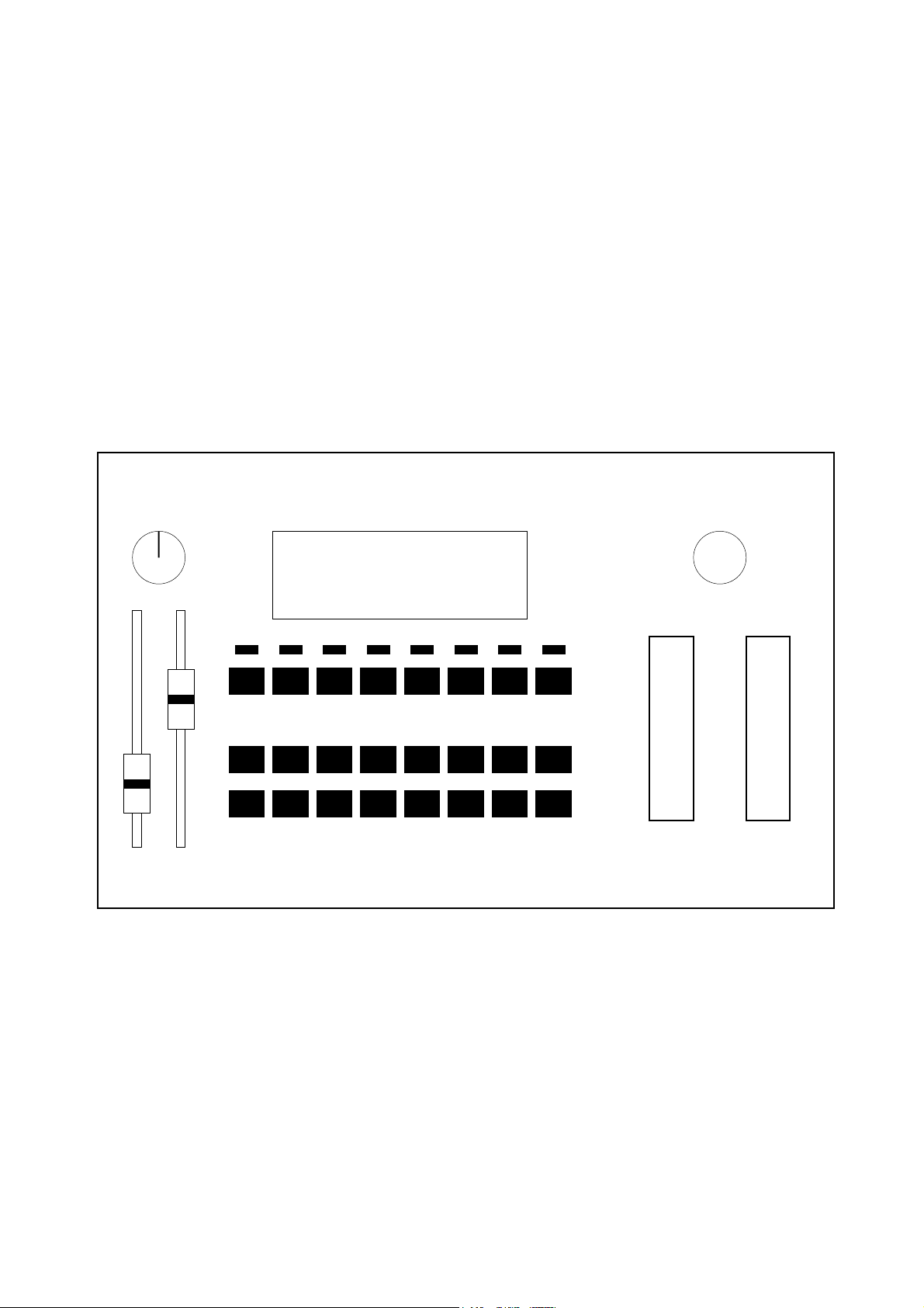
1.4 Controls
The LMK4+ features the following controls and displays:
• Illuminated display with two rows of 16 characters each
• 24 buttons in three rows of 8 buttons each
Upper row: MENU-buttons
Middle row: BANK-buttons
Lower row: NUMBER-buttons
• 8 LED's (serving as indicators for the MENU-buttons)
• 2 Wheels (one spring-loaded)
• 2 Sliders
• 1 Rotary potentiometer
• 1 Rotary encoder (Data-entry dial)
The two wheels, the two sliders and the rotary potentiometer can be used for any MIDI-function desired by the
user (e.g. any continuous MIDI controller). The rotary encoder (data-entry dial) is primarily used for data entry
purposes.
Rotary
Potentiometer
CTR3
CTR1 CTR2
Sliders
Adjustment of LC-Display
Rotary
Encoder
(Data Entry)
LC Display
LEDs
Menu
82345671
Bank
Number
82345671
Wheel 1Wheel 2
The display can be adjusted by means of 2 potentiometers, one for contrast and one for background illumination. If
you wish to change the factory settings insert a thin, insulated screwdriver into the holes to the left and right of the
display and adjust the potentiometers to the desired settings.
In addition LMK4+ is equipped with a monophonic After Touch sensor below the keys that is activated if you put
pressure on the keys pressed down. The After Touch sensor of the LMK4+ is treated like any other controller (i.e.
like wheels, sliders ....). This means it is not limited to send MIDI after touch data but can be used for any MIDIfunction desired by the user (e.g. any continuous MIDI controller).
LMK4+ User's Guide Page 4

1.5 Operating and Safety Instructions
Please follow the given instructions for use of the instrument because this will guarantee correct instrument
operation. Due to the fact that these instructions touch on Product Liability, it is absolutely imperative that they be
read carefully. Any claim for defect will be rejected if one or more of the items was observed. Disregard of the
instructions can endanger warranty.
•
The instrument may only be used for the purpose described in this operating manual. Due to safety reasons,
the instrument must never be used for other purposes not described in this manual. If you are not sure about
the intended purpose of the instrument please contact an expert.
•
The case (flight case) is not a packing suitable for shipment but the case of the instrument. If you want to ship
the instrument via mail, UPS, rail, forwarding agency or others you always must use the original packaging.
Therefore, you should keep the original packaging.
•
The instrument has to be shipped only in the original packaging. Any instruments shipped to us for return,
exchange, warranty repair, update or examination must be in their original packaging! Any other deliveries will
be rejected. Therefore, you should keep the original packaging and the technical documentation.
•
The instrument may only be operated with the voltage written on the power input on the rear panel. Before
opening the case disconnect the power plug.
•
All eventual modifications must only be carried out by a qualified person who will follow the valid safety
instructions. Every modification should becarried out only at the manufacturer or an authorized service
company. Any modification not released by the manufacturer leads to the extinction of the operation
permission.
•
With the introduction of a third person the warranty will be lost. In case of a destroyed warranty seal, any
warranty claim will be rejected.
•
The instrument must never be operated outdoors but only in dry, closed rooms. Never use the instrument in a
humid or wet environment nor near inflammables.
•
No liquids or conducting materials must get into the instrument. If this should happen the instrument must be
disconnected from power immediately and be examined, cleaned and eventually be repaired by a qualified
person.
•
Never subject the instrument to temperatures above +50°C or below -10°C. Before operation the instrument
should have a temperature of at least 10°C. Do not place the instrument into direct sun light. Do not install the
instrument near heat sources.
•
Keep the top side of the instrument free in order to guarantee proper ventilation, otherwise the instrument
could be overheated. Never place heavy objects on the instrument.
•
All cables connected with the instrument must be checked periodically. If there is any damage the cables must
be repaired or replaced by an authorized person.
•
Transport the instrument carefully, never let it fall or overturn. Make sure that during transport and in use the
instrument has a proper stand and does not fall, slip or turn over because persons could be injured.
•
Never use the instrument in the immediate proximity of interfering electronic devices (e.g. monitors,
computers) since this could create disturbances within the instrument and corrupt memory data.
•
The exchange of electronic parts (e.g. EPROMs for software update) is allowed only if the instrument is
disconnected from power supply.
•
When using the instrument in Germany, the appropriate VDE standards must be followed. The following
standards are of special importance: DIN VDE 0100 (Teil 300/11.85, Teil 410/11.83, Teil 481/10.87), DIN VDE
0532 (Teil 1/03.82), DIN VDE 0550 (Teil 1/12.69), DIN VDE 0551 (05.72), DIN VDE 0551e (06.75), DIN VDE
0700 (Teil 1/02.81, Teil 207/10.82), DIN VDE 0711 (Teil 500/10.89), DIN VDE 0860 (05.89), DIN VDE 0869
(01.85). VDE papers can be obtained from the VDE-Verlag GmbH, Berlin.
LMK4+ User's Guide Page 5

2. OPERATION (Software)
2.1 Switching the Keyboard ON
When the keyboard is switched ON a message regarding the software version will appear on the
display for several seconds (e.g. "LMK4 V1.00"). In addition the LED's will flicker for several seconds. After that the
keyboard will go into preset-mode (see below for details) and will call up preset no. 1.
NOTE: When the keyboard is activated for the very first time, the presets will contain random
values since the RAM contains random data. In order to completely initialize the keyboard (i.e.
to set all 128 presets to the same standard values) you have to follow the procedure described in the appendix.
Normally it is not necessary to initialize the memory as this is performed during the final check of the device in the
factory.
2.2 Menu Structure
There are 8 menus available. They are selected via the 8 uppermost buttons. These are referred to
as MENU-buttons. Pressing one will access the corresponding menu. The LED's serve as visual
indicators of the menu selected. You leave a menu simply by pressing another MENU-button. The 8
MENU-buttons correspond to the following menus (from left to right):
1 PRESET
2 PROGRAM CHANGE
3 REALTIME/MASTER CHANNEL
4 SPLIT
5 CONTROLLER ASSIGN/ACTIVITY
6 USER DEFINED CONTROLLERS
7 PRESET PARAMETERS/NAME
8 PANIC
When the keyboard is switched on it will always go to the PRESET-menu. In the next few
paragraphs we will briefly discuss the functions of each of the 8 menus, followed by the operating
procedure for each menu.
1: PRESET
The LMK4+ keyboard allows the storage and recalling of up to 128 complete keyboard settings, referred to as
"presets". Each preset contains data about all 8 keyboard zones with their respective
MIDI-channels, transpositions, allocation and activation of controllers, velocity-response curves, program numbers,
volumes, preset-name, etc. The PRESET-menu is used to call up or store the
presets. The detailed description of the PRESET-menu also includes information on the
MIDI-DUMP-function of the LMK4+.
2: PROGRAM CHANGE / BANK SELECT
This menu serves to send program numbers (MIDI-program change instructions) and bank select data (i.e. MIDI
controller #0 and #32) in direct mode to select the programs and banks of the MIDI-instrument(s) connected to the
LMK4+. The program change and bank select instructions are transmitted via the MIDI-master-channel selected at
the time (also refer to menu 3).
Independent of this, in menu 4 each of the 8 keyboard zones can be assigned a program and bank number which
is sent on the MIDI-channel of the keyboard zone when PRESET is called up (see menu 4: SPLIT).
3: REALTIME / MASTER-CHANNEL
This menu is used to directly transmit MIDI-realtime information (i.e. START, STOP, CONTINUE,
CLOCK) and to select the MIDI-master-channel on which the LMK4+ transmits the direct-mode
program changes and bank select data.
LMK4+ User's Guide Page 6

4: SPLIT
The LMK4+ handles up to 8 different keyboard areas (split areas, split zones, split range) simultaneously.
Overlaps of the zones are possible (i.e. some keys are used by more than one zone). Each zone is assigned a
MIDI channel and to one of the 2 MIDI outputs. The SPLIT-menu
is used to define the parameters of each of the 8 keyboard zones. The SPLIT-parameters are as follows:
• LOWER and UPPER key
• MIDI channel
• MIDI output 1 or 2 or both
• Transposition
• Velocity-response curve
• Aftertouch curve
• Program number
• Bank Select number (= Controllers #0 and #32)
• Volume
In addition in this menu is defined if the zone is used for the (internal) keyboard or the (external) MIDI input.
5: CONTROLLER ASSIGN/ACTIVITY
This menu has 2 different functions:
• Assignment of controllers (i.e. Sliders, Wheels, After Touch etc.) to MIDI-functions
• Activation of the controllers in the keyboard zones
First, each controller is assigned a particular MIDI-function (i.e. pitch bend, modulation, volume, sustain, etc.).
Then the user can decide for each individual keyboard zone whether or not the respective controller is active in
that keyboard zone, i.e. whether or not the corresponding data of the controller will be transmitted on the MIDI
channel and MIDI output of that keyboard zone.
6: USER DEFINED CONTROLLERS
In this menu user-selected controllers (UD1...UD8), which can be used in menu 5, are defined.
7: PRESET PARAMETERS/NAME
In this menu the following preset-parameters are defined:
• Name of the preset
• Preset-pointer (=Number of the next preset reached when switching presets with footswitch)
• Realtime parameters of the preset (i.e. transmission of START, STOP, CONTINUE or none of these when the
preset is called up)
• Scale Black Parameter (Adjustment of velocity-response of the black keys)
• Manual DUMP-function (Dumps contents of Preset-memory via MIDI)
• Transferring the volatile memory data into the non-volatile memory after receiving a MIDI dump
• ATP-Parameter (Positive/negative pitch-bend when aftertouch-sensor has been assigned to pitch-bend-
function)
8: PANIC
This menu provides a PANIC-button which can be used in any operational mode. In addition, the
menu also provides 16 "pseudo-panic-buttons" (for the 16 MIDI-channels) to be used in the event of
one of the instruments connected to the LMK4+ not recognizing the "ALL NOTES OFF"-instruction.
LMK4+ User's Guide Page 7

2.3 DETAILED DESCRIPTION OF MENUS
2.3.1 Preset (1)
This menu is entered by pressing the leftmost MENU-button. Switching the keyboard ON will also
activate this menu. It serves to call up and store presets. A preset is the sum of all information defining a keyboard
configuration. All data about the 8 keyboard zones (i.e. external input or internal keyboard, UPPER/LOWER key,
MIDI channel, Output, Transposition, Velocity and After Touch table, active controllers, Program number, Bank
number, Volume), master-channel, tempo (MIDI clock), allocation of controllers, desired realtime-instructions
during preset call-up, preset pointer and preset name. 128 such presets can be defined by the user and stored for
call-up in the PRESET-menu.
After pressing the PRESET-menu-button the following message appears on the display:
PRS:XXX / PRESET-NAME
B:0YY / N:00Z / >PPP
The upper row lists the preset number selected (XXX=1...128) on the left, the name of the preset selected is
shown on the right. The lower row indicates the bank number on the left (YY=1...8), the
number within that particular bank is shown in the middle (Z=1...8) and the preset pointer is displayed on the right
(PPP=1...128). The preset pointer shows the number of the preset which the LMK4+ will jump to when the presets
are switched via one of the footbuttons (assuming this option is being utilized).
Each bank consists of 8 presets. A bank is selected via one of the 8 BANK-buttons, the number
within the bank is chosen by means of one the 8 NUMBER-buttons. With this method only 64 presets are available
(8 BANK-buttons x 8 NUMBER-buttons = 64 combinations). So the PRESET-menu-button itself is used to switch
between the presets 1...64 and 65...128. The button has to pressed to toggle between the two ranges.
Note: The term "bank" used in this context has nothing to do with the MIDI program bank that is selected by the
MIDI controllers #0 and #32. The MIDI association introduced the MIDI bank term after we used this term for the
bank/number structure of our keyboards. For details regarding the MIDI bank term refer to chapter 2.3.2
PROGRAM CHANGE / BANK SELECT.
Call-up of a Preset
The two bottom rows of buttons on the LMK4+ are used to call up a preset from the PRESET-menu. The upper
row of buttons is used to select the bank number, the lower row to select the number within the bank. Each bank
consists of 8 presets. In combination with the PRESET-menu-button for toggling between 1...64/65...128 all 128
presets can be adressed.
A preset is called up if one of the 8 NUMBER-buttons has been pressed after selecting the
bank with one of the 8 BANK- buttons and selecting the range 1...64/65...128 with the PRESET-menu-button.
Using the BANK-buttons or PRESET-menu-button alone will call -up the preset. Following this procedure each of
the 128 presets can be called up directly.
Once a preset has been called up it is loaded into the so-called work-memory. This memory always contains the
preset currently active. Only the values contained in the work-memory can be modified via the other menus. In
order to modify a preset it has to be called up and loaded into the work-memory, modified while residing in the
work memory and then be stored again in its modified form.
When a preset is called up the content of the work memory is overwritten. Similarily, when storing the content of
the work-memory in one of the preset-memory locations, the old preset stored there is overwritten.
In addition a preset can be called-up by receiving a suitable Program Change message at the MIDI input. The
MIDI channel of the Program Change message has to match to master channel of the LMK4+ adjusted in menu 3
and the preset change via MIDI input must be active (details see chapter 2.3.3: REAL TIME / MASTER
CHANNEL). If the presets of the LMK4+ seem to alter automatically check if incoming Program Change messages
are the reason for this behaviour.
If you do not want to alter the presets via incoming Program Change messages deactivate this function in menu 3.
LMK4+ User's Guide Page 8
 Loading...