

Page 1
DOEPFER MUSIKELEKTRONIK
DREHBANK
Drehbank : The machine w ith the licence to tur n.
Owners manual, 2nd edition.
(Version July 20, 1 999)
Page 2
Doepfer Musikelektronik
Doepfer Musikelektronik GmbH
Geigerstr.13 • 82166 Graefelfing, Germany.
Phone +49 89 89809510 • Fax +49 89 89809510
Internet http://www.doepfer.com
CREDITS:
Project Manager
Programmers:
Hardware design Dieter Doepfer. ! hardware@doepfer.de
Programmer of the Drehbank
systems software for the EditorAdaption and EMAGIC
SoundDiver.
Programmer of the Drehbank
Editor for PC & Presets
Owners manual designers :
Translation
Dieter Doepfer
Christian Assall, Roland Mayer.
Christian Assall. ! software@doepfer.de
Roland Mayer. ! technik@doepfer.de
Roland Mayer, Christian As sall ,
Stephen Doheny, Thomas Rotsch.
Page 3

Foreword
You will have received your Drehbank with software vers ion 1.xx (wher e xx is the
current revision number of the version 1 software). This software has been
checked by Doepfer and by our bet a-testers, an d is believe d to be practicall y bugfree.
But in any new soft ware of such com plexity, we know that it ‘s possible t hat hidden
bugs may still exist. If you find one, we would be grateful if you could let us know
the exact details. We will try to remove the bug as quickly as possible.
To update your device at the current state you then had to contact your local
dealer.
This offer only applies to soft ware f aults . I t do es n‘t ap ply to updates which improve
upon the facilities in your current software, as detailed in this manual.
Actual upgrades of the software will regularly be available to buy.
To update the software, it‘s necessary to open up the Drehbank to change the
EPROM. Users carry this out at their own risk: problems caused by incorrect
insertion of an EPROM are not covered under guarantee.
Throughout this manual, reference is made to various products which have
registered trademarks, without necessarily indicating they are registered. The
absence of the mark shouldn ‘t be taken to imply t hat the product name can be
freely used by an yone. Nor should it imply an y right to use m aterial that is lega lly
protected by a registered trade name or mark, or protected by patent.
Please also take note that DOEPFER Musikelektronik GmbH offers no warranty
and accepts no legal responsib ility for damage caused b y or consequential o n the
use of this equipment, its hardware or its soft ware, or thi s manual. We categoric a ll y
deny responsibilit y. We also reserve the righ t to alt er software and/or the co nte nts
of this manual without notice.
Copyright 1999/2000
DOEPFER Musikelektronik GmbH
All rights reserved. No part of this manual can be reproduced, duplicated or
modified in any form, including electronic means, without the express written
permission of DOEPFER Musikelektronik GmbH.
DOEPFER Musikelektronik GmbH
Geigerstr.13
D-82166 Graefelfing
GERMANY
Tel.: +49 89 89809510
Fax.:+49 89 89809511
Internet: http://www.doepfer.com
Page 4

CONTENTS
Contents
CREDITS
FOREWORD............................................................................................................................ 2
CONTENTS ............................................................................................................................. 5
CHAPTER 1............................................................................................................................. 7
INTRODUCTION...................................................................................................................... 7
A
BOUT THE OWNER`S MANUAL
RESETS
P
/ F
ILES
.................................................................................................................... 8
CHAPTER 2............................................................................................................................. 9
INSTALLATION.......................................................................................................................9
THE HARDWARE UNIT: DREHBANK ...................................................................................9
Options: the 8 external control inputs.......................................................................... 10
Updating the operating system ................................................................................... 10
Software: The Drehbank EDITOR .................................................................................12
NSTALLING THE
I
D
REHBANK EDITOR
System requirements...................................................................................................... 12
De-installation .................................................................................................................13
Updating the Editor Software.......................................................................................... 13
The Editor on the Emagic SoundDiver(OEM-Basis) for PC& MACINTOSH. ................. 13
CHAPTER 3........................................................................................................................... 14
THE BASICS.......................................................................................................................... 14
HAT IS THE
W
EATURES
F
HE FRONT PANEL
T
D
REHBANK
............................................................................................................................ 14
................................................................................................................ 15
64 control knobs/potentiometers..................................................................................... 15
64 Labelling pads............................................................................................................ 15
SWITCHES..................................................................................................................... 15
recalling the original settings/ Rom presets ................................................................ 15
Switching between the 2 banks................................................................................... 16
Creating and sending a Snapshot............................................................................... 16
L.E.D.s ............................................................................................................................16
The Drehbanks operation indicator sequences ......................................................... 16
Bank indicators............................................................................................................ 17
Snapshot Mode ...........................................................................................................17
Midi events Indicator ................................................................................................... 17
Midi transfer errors...................................................................................................... 17
Non volatile memory/presets .......................................................................................... 17
Power input/ Power supply ............................................................................................. 18
T
HE
MIDI C
DITING WITH THE EDITOR SOFTW ARE
E
ONNECTION
CHAPTER 4........................................................................................................................... 21
THE EDITING SOFTWARE................................................................................................... 21
O
PENING AND SAVING A PRESET
PENING A LIBRARY
O
ONTROLLER PROPERTIES
C
RESET SENDING AND STORING
P
YSEX FILES
S
/ P
............................................................................................................. 21
RESET TEXT FILES
Generating SysEx files.................................................................................................... 23
Generating Text files....................................................................................................... 24
DITOR TOOLS
E
..................................................................................................................... 24
Copy Bank 1 ---> Bank 2 ................................................................................................ 24
Copy Bank 2 ---> Bank 1 ................................................................................................ 24
Init Bank 1....................................................................................................................... 24
................................................................................................ 7
...................................................................................... 12
?..................................................................................................... 14
........................................................................................................ 19
................................................................................... 20
............................................................................................ 21
................................................................................................... 22
............................................................................................. 22
........................................................................................ 23
5555
Page 5

Init Bank 2....................................................................................................................... 24
Exchange Bank 1 <---> 2................................................................................................ 24
PTIONS
O
.............................................................................................................................. 25
Event Thru ......................................................................................................................25
Realtime Thru ................................................................................................................. 25
System Exclusive (SysEx) Thru...................................................................................... 25
E
DITING A CONTROL FUNCTION
.............................................................................................. 26
CHAPTER 5........................................................................................................................... 33
APPENDIX............................................................................................................................. 33
ROM P
RESET
1 ................................................................................................................... 33
Bank 1............................................................................................................................. 33
Bank 2............................................................................................................................. 33
Key to Midi controller numbers ......................................................................................34
O
PTIONS FOR THE EXTERNAL CONTROL INPUTS
...................................................................... 35
Control voltage operation................................................................................................ 35
Foot controller Operation ................................................................................................36
B
IBLIOGRAPHY
...................................................................................................................... 38
6666
Page 6

CCHHAAPPTTEERR 1
1
IINNTTRROODDUUCCTTIIOON
N
Chapter
1
Introduction
About the Owner`s manual
This manual is intended for those who enjoy to browse through instruction
manuals, and for those of you who have pick ed this book up f or the ver y first time,
only because something doesn`t work or through misuse of the Drehbank
irreparable damage has been caused to the future of all mankind. ☺
But jokes aside, systems damage through use of the Drehbank is almost
impossible.
The worst things that can happen to the us er during use are ( 1) that the com puter
crashes, (2) you experience a systems error which can only be cured by the
resetting of your computer, (3) you exper ience a systems error while in the editor
program before you have saved the data.
But before you integrate the Drehbank onto your Midi setup please read the
following chapters to see which system s are c ompatib le and how you sho uld i nstal l
the editor software.
So as not to become conf used while rea ding the m anual we rec omm end that you read
each chapter through from start to finish and in order. In that way each chapter will
make more sense.
We also recomm end that you read the RE ADME.TXT file on the Editor disc and
print it out because the information on the disc will be m ore up to date than t he
information found in the manual.
Warning
This goes especially for units that ar e sold after February 1999. Here you
will find several im portant notes on the 4 ROM presets, information on
which is not listed in the manual, also any errors that we have found in the
writing of the manual will be updated in the README.txt file.
Also after the installation of the editor program you will find an built-in
'DB_HELP.HLP' help file available to you online. In th is file you wil l find the m ost
up to date information on the Drehbank Unit.
Site address:
http:// www.doepfer.de/pub/download.htm
7777
Page 7

INSTALLATION
Presets / Files
There are several preset files incuded on the Editor Disc ! README.TXT file.
These can be used directly or used as a basis for creating your own preset
libraries.
We at Doepfer are continually creating new presets that will be available for
downloading from the InterNet.
Site address:
http:// www.doepfer.de/pub/download.htm
NOTE
Information that we feel is of extra importance is printed in boxes of gre y
and black like this one throughout the manual.
8888
Page 8
Installa tion
INSTALLATION
Chapter
2
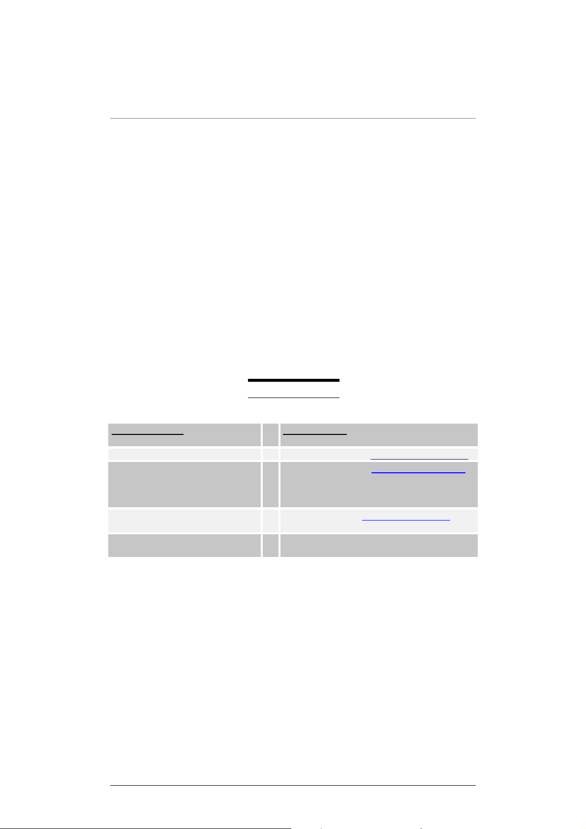
The hardware unit: Drehbank
Front panel
• 64 control knobs
• 64 labelling pads (for the user to label the function of each control knob).
• 3 switches (on the left side of the unit; black):
-
(one) to create a „Snapshot“ (the top switch)
-
(two) to switch from one bank to the other (the lower 2 switches)
• 3 L.E.D.s, one above each switch which indic at e:
-
When a 'Snapshot“ is being sent
-
Midi events
-
Which of the two banks is in use
Drehbank
DrehbankDrehbank
Back panel
• 8 external control inputs (optional)
• Power input connection
• Midi Ports
-
MIDI-In
-
MIDI-Out / Thru (Merge)
9999
Page 9

INSTALLATION
OPTIONS: THE 8 EXTERNAL CONTROL INPUTS
If you have a unit fitted with the optional external contr ol inputs, you will find th e 8
external inputs at the rear of the unit (labelled external inputs)
The 8 external inputs are assigned to the following control knobs;
External input
(at rear, left to right)
1 31 Control voltage
2 15 Control voltage
3 47 Control voltage
4 63 Control voltage
5 32 Foot controller
6 48 Foot controller
7 16 Foot controller
8 64 Foot controller
NOTE:
Further information on the external control inputs is to be found in the
Appendix
UPDATING TH E OPERATING SYSTEM
For this you will need a new EPROM, a Phillips sc re wdriver, and an I.C. t ool. If you
don‘t have your own EPROM burner we will send you a new EP ROM (you must
pay for the post and package costs).
Control knob on front panel Default settings
NOTE
If you decide to update yourself you‘ll have to exchange the old
EPROM against one with the latest software.
First of all, ensure that the unit is dis con necte d from the m ains. When installing the
new EPROM mak e sure to i nstall i t in th e corr ect posi tion, t he notch on o ne si de of
the component is there to guide you. The EPROM I.C. socket should have a
corresponding mark. Be careful when installing the new EPROM because the
component is quit e delica te.T o exc hange t he EPRO M we recom m end that you pull
it out horizontally eg. with two screwdrivers simultaneously or with a specialized
I.C. tool. Be careful not to to damage the component by bending it s pi ns . T he s ame
care is needed for the installation of the new component. Don’t push too hard!
Check that the pins of the new component are not bent out of shape.
10
10
1010
Page 10

INSTALLATION
The EPROM component.
Sticker with
version num ber
Notch
• Before you reassemble the unit make sure that
-
the EPROM is inserted correctly (if incorrectly inserted then it‘s goodbye Mr
EPROM when you turn on the unit)
- you haven‘t loosened or disconnected any of the components or the wiring.
With the second vers ion of the Drehbank series (a vailib le from Februar y 1999 and
identifiable b y the 3 switches and L.E.D.s) the no n-volatile EEPROM memo ry is
doubled. Therefore, with each control knob you can generate a Midi-string
comprising 113 bytes, instea d of 55 bytes as is the case with un its from the first
series.
If you want to update the first ser ies you‘ll n eed soft ware versions above 1.1 and a
new EEPROM memor y chip (type X25128). W ith this installation please take the
same care recommended for the EPROM update (see previous page).
You’ll find the EEPROM memory chip (with the notch of the EPROM pointing
upwards) on the right hand side of the processor (that‘s the large black square
component at the centre of the c ircuit board) . Owing to th e small si ze of the chip it
may not have a notch to guid e you, but it does h ave a spot - ind icating pin no. 1 printed in one corner to act as a guide. This point s hould be in the c orner furthest
away from the processor when correctly installed.
Only power up once you have correctly reassembled the unit and screwed the
case back together.
11
11
1111
Page 11

INSTALLATION
Software: The Drehbank Edi tor
On the included DOS–formated disc you will find the Drehbank editor software.
Warning
Before you install the editor program (Please, Please, Please) read the
README.TXT(help) file.
Installing the Drehbank Editor
System requirements
The Drehbank Editor is a Windows application which requires the following system
• IBM compatible PC .
• CPU > 90 Mhz (recommended)
• > 8 Megabyte RAM (recommended)
• > 2 Megabytes of free space on the hard drive/disc.
• Windows 3.x, Windows 9x, or Windows NT.
• VGA Monitor with a resolution of at least 640x480.
• MIDI Interface (e.g. soundcard with MIDI Interface).
• Multimedia Midi cable to connect the Drehbank.
• 3.5“ floppy drive or InterNet connection.
• Drehbank.
The editor program als o works without a Drehbank, because the program needs
no feedback from the Drehbank.
12
12
1212
Page 12

INSTALLATION
Installation
To install: initiate/execute INSTALL.EXE. Once you‘ve installed the application
you’ll find a subfolder titled Drehbank in the directory you have chosen.
You can also create a link on the desktop for quicker access to the editor
application. To start the program simply doubleclick on the Drehbank.EXE file.
De-installation
The editing software has no effect on the operating system of your computer,
therefore you can simply delete the Drehbank folder from your hard disc.
Updating the Editor Soft ware
You will always find the most up to date version of the editor software on the
Doepfer homepage: http:// www.doepfer.de/pub/download.ht, stored as a file titled
DBXX.ZIP where XX stands for the version number. For example version 1.1 is
titled DB_11.EXE. Simply download the file, unpack it into a temporary directory
and install it in the same way as a new installati on.
The Editor on the Emagic SoundDiver(OEM-Basis) for PC&
MACINTOSH.
From autumn 1999 we at Doepfer hope, that we will be able to offer a special
version of the Emagic SoundDiver program.
This could be very interest ing alongside an existing Drehbank edi tor as those of
you who work with the SoundDiver won‘t have t o switch to a new edit or program.
Above all it gives
without having to buy a P.C.
Further Information on this topic can be attained by reading the R EADME file on
the disc or on our homepage.
When available it will become part of the standard Drehbank package.
We cannot offer this software on the Inter Net to downl oad free of charge b ecause
the OEM-Version from Emagic is not public domain software.
Macintosh
users the possibility to edit their Drehbanks
☺
13
13
1313
Page 13

CCHHAAPPTTEERR 3
3
BBAASSIICC OOPPEERRAATTIIOONNS
S
Chapter
3
The Basics
What is the Drehbank?
Doepfer
Doepfer
The
DoepferDoepfer
control knobs.
Any midi event can be assigned to any control knob. Each knob lets you control
Midi events in the f orm of Midi-str ings. You can co ntrol sim ple events like volum e,
reverb, panorama, etc., or you can create complex SysEx strings.
Drehbank is a user definable Midi control unit with 64 rotary
The setting of each con trol knob is stored in a preset . A preset is organized into
two interchangable bank s, each containing 64 c ontrol knob func tions. The presets
are normally create d in the Drehbank editor, store d on a PC, and from ther e sent
to the Drehbank
You can store a preset in the non-volatile memory (EEPROM) of the Drehbank. So
that the PC editor pr ogr am can have a litt le snoo ze as s oon as the preset is s tored
in the memory of the Drehbank.
.
☺
Fea tures
• 2 banks (each activated by a corresponding switch)
• indicators for the activated bank (2 L.E.D.s one above each bank)
• 64 controllers per bank, each with the following parameters:
-
Midi strings with a maximum of 113 bytes per string.
-
Up to 16 definable variables per Midi string (each variable needs 7 Bytes).
-
Any variable can be assigned to any control knob.
-
For the variables there are 20 predefined data formats available.
-
The scale and range of each variable is adjustable.
-
control resolution can be definable up to 255 steps.
-
control threshold adjustable from1 to 255.
-
The offset and reference voltage of the AD converter is adjustable in 12 steps
per control knob.
• The non-volatile saving of presets (2X64 control knobs).
• „Plug & Pray“ ☺ !You „s witch on“ and the preset f rom the non- vol atile m emory
works.
• The possibility to connect 8 external controllers.
• ‚Snapshot' function.
14
14
1414
Page 14

BASIC OPERATIONS
The front panel
64 control knobs/pot entiometer s
Drehbank incorporates 64 control knobs/potentiometers that have a control
voltage range from 0..+5V. Internally the control volta ge is translated into digitial
information. A full turning of the control knob has a range of 256 values from
0..to.255.That means that the variables have a range of 256 steps.
Note
There may be slight fluctuat ions in the potentiometer tolerance levels f or
which we accept no liability.
The spacing between the potentiometers is rather small. We know. This is a
compromise owing to the exeptionally large num ber of control knobs . Would you
buy a unit that‘s 8 feet long? ☺
64 Labelling pads
These pads allow you to label each individual contr ol knob for easy ref erence of
your setups.
Note
Only use light pencils when writing on the labelling pads, otherwise it
won‘t be possible to use the pads again and again.........
SWITCHES
On the left of the unit you`ll find 3 black switches with the following functions:
RECALLING THE ORIGINAL SETTINGS/ ROM PRESETS
As you will see the Drehbank unit has no ON button/switch. T o activate the ROM
presets you must pr ess a switch at the same tim e as you plug the power In (see
the README.TXT file).
The indicator above the pressed s witch will not light up, but instead the other two
indicators will flash.
E.g., when turning the unit on you press switch 1 (the to p switch), to select ROM
preset 1. The L.E.D. above that switc h will not light up, b ut the other 2 L.E.D.s will
light up. This inverted indication system also goes for the recalling of the other
presets.
This means that the Drehbank at that moment loads t he ROM preset and will wait
until you release the switch.
After this the Drehbank returns to normal op eration mode a nd switches to bank 1,
the L.E.D.s are now also in normal operation mode.
Now the Drehbank is ready to ROCK. ☺
15
15
1515
Page 15

BASIC OPERATIONS
The recalling of the ROM pr esets has no eff ect on the no nvolat ile m em or y (EEPROM).
The preset that you loaded f rom the editor software into the nonvo latile memory still
exists. To activate it again you must turn the unit off and on again.
SWITCHING BETWEEN THE 2 BANKS
For each bank there is one switch and one L.E.D. indicator.
Simply select a bank by pressing either of the bank switches on the Drehbank
The Drehbank will then activate the selected bank, which is indicated by the
flashing of the L.E.D. above the pressed switch.
CREATING AND SENDING A SNAPSHOT
To create a Snapshot you must first pr ess the top s witch (lab elled snap). W hen the
switch is pressed f or about a se cond the L.E.D. (that is other wise inactiv e except
for Midi activities) blinks rapidly. Press the switch again within a second and a
Snapshot will be sent, indicated by a long flash of the L.E.D. This flash is
important, because if you trigger a Snapshot ac cidentally ( or at the wrong tim e)
you could overload the Midi connection.
Once the Snapshot has been sent the Drehbank
returns to bank indicator mode.
.
Important
If you change your m ind and don‘t wa nt to send a S napshot (or if you go
into the mode by accident) j ust wait until the L.E.D. stops blinking, (af ter
one second)
Remember
A Snapshot sends the controller valu es of all 64 knobs from the active
bank.
L.E.D.s
The L.E.D.s are on the left side of the unit, one above each switch.
They indicate the different operation modes and actions of the
OPERATION INDICATORS
When the Drehbank
seconds. In this time the data from the non-volatile memory (EEPROM) is
transfered to the work buffer (RAM, volatile memory) of the unit. When this is
completed the L.E.D.s s witch off and th e L.E.D. that indica tes bank 1 li ghts up, as
bank 1 is then active. If this does not happen then either the power input is not
correctly connected to the Drehbank or it‘s possible that the plug or the Drehbank
has a defect.
is switched on all 3 L.E.D.s li ght up and stay lit for about 5
Drehbank.
16
16
1616
Page 16

BASIC OPERATIONS
BANK INDICATORS
The indicators show which bank is active:
-
L.E.D lit over Bank 1 (Bank 2 off) indicates BANK 1 is active.
-
L.E.D lit over Bank 2 (Bank 1 off) indicates BANK 2 is active.
SNAPSHOT MODE
Once the snapshot switch has b een pressed the L.E. D. above it blink s rapidly. By
pressing the switch once again within a second a „Snapshot“ will be sent and this is
indicated by the L.E.D staying lit (agai n for about a second) . After this the L.E .D.s
returns to bank indicator mode.
MIDI EVENTS INDICATOR
Under normal operating the L.E.D. wh ich indicates th e Snapshot m ode is switched
off. For that reason this L.E.D. ( top ) is also used to indicate Midi events.
The L.E.D. flashes for every activity on the Midi bus (both Midi In, and Midi Out).
Midi events are norm ally performed very quick ly and therefore the flashing of the
L.E.D. is hardly noticeable. Turn a controller and watch the glow of the L.E.D.
The indicator also s hows if a c ontro l k nob is se nding an eve nt. Als o you can see, if
the Drehbank is receiving Midi data.(e.g.the receiving of information from the
editor program.)
MIDI TRANSFER ERRORS.
If the Drehbank experiences an error in the receiving of data, the unit will turn the
bank indicator off and switch on the Snapshot L.E.D . which will flash continua lly.
Despite this the
switch you can reactivate the Bank and Snapshot indicators.
Note
Under normal operating conditions this error should not occur.
Drehbank
unit is still operational. By pressing the Snapshot
Non volatile memory/presets
When you turn on the Drehbank without going into the editor pro gram you’ll find
several complete presets already available.
These are:
-
The Fixed ROM Preset s, which are found on the EPROM, with the o peration
software of the Drehbank, but this can only be altered by updating the
EPROM.
17
17
1717
Page 17

BASIC OPERATIONS
Note:
The layout of ROM preset 1 is printed in the appendix. Information on
ROM presets 2, 3, and 4 is found in the README.TXT file.
- The Changeable non-volatile EEPROM Preset. T his preset is located in the
internal non-volatile memory (EEPROM) and will under normal operating
conditions be loaded into the work buffer (RAM).
Power input/ Power supply
The Drehbank is powered b y an externa l DC power sup ply. A 230V po wer suppl y
with Euro plug is included in the pac kage. For countries with different vol tages or
plug sockets you’ll have to buy the appr opriate power supply in your country (9 V
DC@250mA output required ). On the unit there is no On/Off s witch. So to tur n the
unit on and off you have to connect / disconnect the power cable. Alternativ ly we
recommend using a multiple mains socket with an On/Off switch.
18
18
1818
Page 18

BASIC OPERATIONS
The MIDI Connection
The Drehbank merges the Midi data coming into the Midi In port with the
generated data of the res pective contr ol knobs. T he complete m erged data is then
sent to the Midi Out port.
Note
Drehbank normally works in Midi Merge mode.
Important
If there is a lot of data coming into the Midi In port it is possible that the
Drehbank will have problems with merging, as the internal memory has a
limited capacity.
When transferring a lot of Mid i events we recommend the use of an
external merger.
The Drehbank editor a nd the Drehbank communicate via M idi. This requires a
sound card with Mid i interface or a s pecial M idi card that wor ks with the Windows
multimedia driver (e.g. the Unitor from Emagic). You can co nfigurate the Midi In
and Out ports through the Windows menu titled Multimedia/Midi.
Drehbank to the 15- pin Sub-D sock et on
Use a Multimedia c able to connec t the
your soundcard joystick connection).
Connecting the Drehbanks Midi Out to the P.C. is not necessary, because
the Drehbank
Note
Please take care that you don ’t cr eate M idi loops, because the PC c ould
crash!
To avoid creating loops we have built in the opt ion to deactiv ate the m erge m ode in
3 steps ( found in the editor program).
doesn‘t require a "handshake".
19
19
1919
Page 19

BASIC OPERATIONS
Editing with the Editor software
The basic concepts of editing with the edit or sof tware are bas ed upon t he "Dr ag &
Drop" principle. In "Control Copy" mode you can „drag“ a contro ller and „drop“
on the chosen control k nob; you use the „drag and drop“ also when work ing with
the library. In „Control Exchange“ mode you can exchange the controllers. To
switch between the modes press the following symbols.
--->+
<--->
If you „drop“ something uni ntentionally, DON’T P ANIC, there is a seperate undo
function for each bank.
Every step you m ake will be sent str aight to the Drehbank so that you can check
every function right away.
You can „Drag“ and „Drop“ from bank to bank. First: click once on the bank
symbol „Drag“ and then select the bank with t he arr ow k e ys, Then c lick on „Drop“
in the selected position.
If you click with the rightmouse above a control, you’ll go into the „Properties
Dialogue“. Here you can change various parameters of the control knob functions.
for "Control Copy" mode.
for "Control Exchange" mode.
If you‘re big into Midi then with a doubleclick of the leftm ouse you can access the
edit control dialogue. Here you can also create SysEx strings.
Warning
If you don’t have the “Know How“ you sho uld lea ve Edit Control Dialogue
alone!
The GM_LIB.DBP file inc ludes the complete contro l functions of the Gener al Midi
Standard.
20
20
2020
Page 20

The Editing Software
Opening and saving a Preset
The
Drehbank editor includes some presets that you can use as a basis for
creating your own preset files.
Click in the „preset“ menu on open to
access the data brows er. There you can
select a preset and load it by clicking on
O.K. The information in the preset is
then loaded to the Drehbank editor and
sent to the Drehbank unit.
To save a preset click on save in the
„preset“ menu
in the data browser. Take care when
writing the file name, the letters .DBP
must appear at the end of the file name
e.g."NONAME.DBP"
,
and then title the preset
Chapter
4
Opening a Library
To create a preset, you have the option to use the original control functions
settings in the Library. Click in the"Library" menu on open to access the data
browser. Select a librar y file and then click on O.K..You will see th e „Descriptions“
of the control functions listed in the library window on the Drehbank editor.
Note
You can also open a preset as a library, to enable you to use the contro l
functions from other presets.
The difference between presets an d libr ar ies is t hat t he Libraries are formed from a
collection of „Uni versal“ co ntroller functi ons, whereas presets are bui lt from control
functions that perf orm specialized jobs . For e as ier us e th e pr esets a nd libraries ar e
tored in different folders.
21
21
2121
Page 21

USER INTERFACE
Controller Properties
Most of the control func tions from the libraries have variables with whic h you can
control Midi events e.g. Midi channe l.
To change the properties of a knob click once on the
rightmouse and then on „prop erties“ . Now you‘re going to get
what you’ve been look ing for! (the properties m enu,
☺. Here you can alter the settings of the selected control
knob with the pop up menus, e.g. Midi channel, controller
numbers. To activate t he ch anges click on „
abort.
O.K.
yippee
or cancel to
)
When the Drehbank is connected correctly to the P.C editor you can then
immediately check the revised control functions.
Preset sending and storing
" Send Preset" button you send the complete preset from the
When you press the
editor to the volatile memory (RAM) of the Drehbank
button you copy the c omplete preset into the non-volat ile memory (EEPROM) of
the Drehbank. This tak es about 82 s econds. During this eternity ☺ the L.E.D. will
blink constantly.
.
.
With the „Store preset“
. .
22
22
2222
Page 22

USER INTERFACE
Note
1. Don`t forget to save your preset.
2. When you switch the unit O ff and On again the n on-volatile memor y
still exists.
Sysex files / Preset T e xt files
SysEx Files .SYX are files with one or m ore MIDI system exclusive messages in
binary code.
The Drehbank
that a complete Drehbank SysEx File is built f rom 128 sin gle S ysEx m essages ( 2
banks with 64 control knobs per bank).
Remember
needs to have one se parate S ysEx mes sage per c ontrol knob, s o
SysEx stands for "System Exclusive Message". SysEx is a Midi event
that has only one norm. This norm begins with byte F0 ( Start of System
Exclusive Statusbyte) a nd ends with byte F7 (End of System Exclusive
Statusbyte).
All bytes between F0 a nd F7 are freely definable. The format for SysEx
implementation is usually to be found in the manual of the equipment you
are using with the Drehbank.
Generating SysEx files
Select "Make Sysexfile" from the
"Preset" menu and a dialogue window
opens. Here you can selec t t he knob you
want to integrate into the SysEx file.
Click on O.K. to open the data browser
so as to name and save the file. Make
sure that at the end of the file nam e you
type .SYX
You can send these SysEx files from a
sequencer or a SysEx dumper to the
Drehbank.
Warning
When dumping Sysex data from a sequencer or SysEx dum per to the
Drehbank make sure that between the SysEx information of each control
knob there is a gap of at least ten (or more) milliseconds. If the gap is not
long enough then it is poss ible that you could overload the Midi buffer .
An Midi buffer overload is indicated by the constant glowing of the L.E.D.
23
23
2323
Page 23

USER INTERFACE
Generating Text fil es
If you click on "Make Textfile" in the "Preset" menu you can generate a textfile to
document your SysEx files. In this case make sure that the letters at the end of the
file name are .TXT
Editor T ools
In the "Tools" menu the following functions are available.
Be aware: there is no undo function!
Copy Bank 1 ---> Bank 2
Copies all of the control functions of bank 1 to the control functions in bank 2.
Copy Bank 2 ---> Bank 1
Copies all of the control functions of bank 2 to the control functions in bank 1.
Init Bank 1
Returns all the contro l functions in Ba nk 1 to their d efault settings: M IDI Controller
0 to 63 for controls 1 to 64.
Init Bank 2
Initiates all the contr ol functions i n Bank 2 to t heir default settings: MIDI Controller
64 to 127 for controls 1 to 64.
Exchange Bank 1 <---> 2
Swaps the control settings of bank 1 with those of bank 2.
Be aware: there is no undo function!
24
24
2424
Page 24

USER INTERFACE
Options
Go into the main menu and click on „options“. Here you will find the following
options -
The Midi Thru Mode in the Drehbank
determines which type of MIDI
messages "get-THRU-ed" from the
Drehbank Midi Inputs to the Drehbank
Midi Outputs.
Event Thru
When enabled all Midi channel me ssages e.g. note events, controller e vents from
Midi In are forwarded to Midi Out.
Realtime Thru
When enabled all Mid i realtim e mes sages e.g. start, s top, t iming clock from Midi In
are forwarded to Midi Out.
System Exclusive (SysEx) Thru
When enabled all Midi SysEx messages from Midi In are forwarded to Midi Out.
25
25
2525
Page 25

USER INTERFACE
Editing a control function
Doubleclick the control knob you want to edit and you will get the Edit Control
dialogue. If you are not f amiliar with MIDI deta ils you should tak e a l ook at the MIDI
1.0 Specification and the Midi Table. Further take also a look how theTables works.
After all (if you are a profes sional in MIDI) tak e the Tec hnical M anual of the d evice
you want to control with the Drehbank. Here you will find (m ostly) its special M IDI
implementation. For hexadecimal codes you will need the conversation table or
better use the scientific Calculator (->XG-Sysex Example).
If you are complete confus ed of this hexadecim al arithmetical m ysteries, you may
find a library that already contains the function that you are l ooking for. For GM a nd
XG compatible dev ice you have already everything you need in the libr aries and
there are several more for other specific devices. The ability to edit a control
function is made as a tool f or M idi pros . Normal users who onl y work with s tandar d
events like Midi Controller etc. should not need to edit a control knob this way.
(Notice that your ed iting can also result i n useless Midi Tr ash which may conf use
or hang up some Midi-Expanders or the PC !).
26
26
2626
Page 26

USER INTERFACE
Edit Control: M idi - S tring
Here you input the byte sequence of the desired MIDI event in hexadecimal
notation. You can sep arate the bytes using spac e but this is not n eeded (e.g. B0
07 X0 for Volume Controller in Ch 1).
Remark
Hex is the abbreviation for hexadecimal. HEX is a numerical
system (like decimal) using the following 16 characters: 0, 1,
2, 3, 4, 5, 6, 7, 8, 9, A (=10), B (=11), C (=12), D (=13), E
(=14), F (=16)
There are 16 different variables X0..XF you can use in the string for realizing
control properties. If you need onl y one variable for the value b yte of the function
(e.g. the value byte of a Midi-Controller ) just use X0 and set its source on "f rom
itself". This causes the Drehba nk to replace X 0 with t he curr ent v alue of the c ontrol
knob.
Remark
A Midi string is a chain of Midi bytes transmitted via the Midi
interface to represent a Midi event. Well-known Midi events
are e.g. note-o n, note-off , program chan ge, controller, p itchbend after-touch.
Edit Control: Description
Input here a description which ident ifies the contro l function. The m aximum length
is of the description is 80 characters. You may also values, parameter names or
table terms in the description. Use the following shorthand expressions:
!XN decimal value of XN
?XN parameter name of XN
$XN entry from the associated table
"N" stands for the number of the variable and must be replaced by 0...F (i.e.
X0...XF).
Putting variables in the desc ription str ing ma kes only sense if the y are ass igned as
a property of the control function.
Examples therefor e can be f ound i n every good library or preset e.g. the GM-Mix er
Preset "GM_MIXER.D BP" in which the control f unctions all ha ve propert ies to alter
the Midi-Channel and the Controller-number whereby this values also appear
"dynamically" in the description.
27
27
2727
Page 27

USER INTERFACE
Edit Control: Label
Input here a label for the control knob. Labels can have a max. length of 16
characters. You can also put valu es of variables in it using !XN, ?XN, $XN in the
label, the same way as for the description.
Note
Use low case characters to match in the box without
truncation. It is also recommended to use abbreviations (e.g.
"ctr" instead of "co ntroll er") .
Edit Control: Variable Assi gnment
You can use 16 diff erent variables X0..X F within the Midistr ing. As def ault t hey are
all assigned to repr es ent t he va lue of the control k nob its e lf . Eac h vari ab le c a n a ls o
be assigned by altering its param eters for more complex functions e .g. to realize
SysEx strings which includes chec ksum or values hav ing another data form at. You
can also define a value that is linked from another control knob.
Click on the button with the name of the variable or doubleclick on the variable
directly in the Midi string to get the dialogue for the corresponding "Variable
Assignment". After that in the Edit Control dialogue the Variable Assignment
window is added or changes if you select another variable.
To select another variable you have to repeat the whole procedure. It is not
necessary to close this window. You may continue the input in the Edit control
window.
If you Cancel the Edit Control dialogue the inputs of the Variable Assignment
window are cancelled as well.
Edit Control: Source
Here you select the source of the variable (X0...XF). This means that for the
regarding XN the co ntrol valu e of the c urrent con trol knob is insert ed. But you m ay
link a value from another control knob b y selecting "fixed fr om control xy in bank
z". The value for the XN in question is now taken from these control knob.
As default each variable is assigne d to r epr es en t th e val ue of the control knob it self
(from itself) with a range of 0...127 and a resolution of 1 digit (Step=1).
Remark
The value of a control knob results from ist position in a
proportional rel atio n.
If you select "From Properties" the XN is adjustable in the properties dialogue.
Values for properties are set directly in the corresponding properties dialogue of
the editor and transmitted to the Drehbank as constant values.
You can make a control function more flexible and universal by using property
variables. W ith properties you can make changin gs of the control function e.g. of
the Midi channel "on the fly".
28
28
2828
Page 28

USER INTERFACE
Edit Control: Type
Here you can select th e data form at of the variable. As default eac h Xn is defined
as "Normal byte" which is mos tly used. The bit weight notation of a normal b yte is
<76543210>. You h ave a lso the c hoic e of oth er f ormats that you sh ould onl y use if
you know what you are doing - if you do not, it is the best way to let it be "nor mal
byte".
Remark
The poperties dialogue supports only the normal byte
format.
Edit Control: Table
To show the values of property variables in plain text (e.g. Controller names
instead of numbers ) and for easier ed iting each vari able is assoc iated with a tabl e
that contains plain text for each value. The setting of the table takes no effect in the
control function and is also left unrec ognized by the Dre hbank. If you dont need a
special table then let it be on "Hex".
Attention
The settings of th e t ables are used only in the editor and has
no meaning in t he DREHBANK devi ce.
Edit Control: Range Fr om
This setting represents the value of the assigned control knob at its left end
position (ccw, fully counter clock wise). For property variables this defines the
lowest available valu e.
Edit Control: Range To
This setting represents the value of the assigned control knob at its right end
position (cw, fully clock wise). For property variables this defines the highest
available value.
Note
You obtain an inverted control characteristic if "Range to" is
lower than "Rang e fro m".
29
29
2929
Page 29

USER INTERFACE
Range to
e.g. 120
Range from
e.g. 20
ccw cw# control range ! ccw cw# control range !
Range from
e.g.120
Range to
e.g. 20
The left picture shows an example with Range from = 20 and Range to = 120. If the
knob is turned from left (ccw) to right (cw) the data 20...120 are generated.
The right picture shows an example with Range from = 120 and Range to = 20. If
the knob is turned from left (ccw) to right ( c w) the dat a 120... 20 are g enerat ed. The
characteristics is reverse compared to the first example.
Edit Control: Step
Here you set the step r es o lut io n of the c or res pond in g control va lue . As default step
is set to 1 for havin g the full resoluti on. The 4 pictures show increasing values f or
the step parameter. The step value cannot be less than the Threshold value.
30
30
3030
Page 30

USER INTERFACE
Edit Control: Value
For property variab les this is the current or default value. If not on propert y, this
parameter is transmitted to Drehbank but not yet used. For the future this may be
used as default value, so set it as default e.g. as the center value for Panorama
Controllers or 100 for volume controllers having a headroom of 27 digits.
Remark
For variables not assigned to the Properties Dialogue this
value has no me ani ng !
Edit Control: Sample- Rate
This parameter s ets the sample rate of the contro l knob. It is s hown as the c ycle
time in which the control k nob is s canned f or its valu e. Each new value causes the
Drehbank to send out the Midistring. If the device that you control with the
Drehbank is not able to proces s the data coming from the Drehbank decrease
this value to lower the data stream (e.g. if the message "MIDI buffer full", "MIDI
overflow" or similiar appears in the display of the device controlled by the
Drehbank).
Edit Control: Threshold
Here you can set the t hreshold for the contro l knob. A new Midistring will only be
sent if the new value of the control knob differs more than the threshold value.
Increase this setting to supress redundant Midi data caused by minimal
fluctuations. Higher settings lower the Midi data stream and suppress undesired
minimal fluctuations. The step value (see above) cannot be smaller than the
treshold value.
Edit Control: ADC_GND/ADC_REF
The values of ADC_GND and ADC_REF def ine the working range of the internal
ADC (analog-to-digita l con verter ). T he 64 con trols of the Dreh bank c over a v oltage
range of 0...+5V as th e rotary potentiometers used ar e connected between GND
and +5V. The setting for ADC_GND or ADC_REF should be changed only if a
external control vol tage or foot co ntroller is used that cov ers not t he whole voltage
range of 0...+5V. If the maximal or minimal data values cannot be reached the
values for ADC_R EF or ADC_REF may be changed to obta in the complete data
range. Especially many foot controllers do not cover the whole voltage range as the
potentiometers inside do not turn the full cw-ccw range but only a part of the f ull
range.
31
31
3131
Page 31

USER INTERFACE
Building a Library
Since the Drehbank library files use the s ame file format as the pres et files they
are made as a Preset using t he Ed itor. T he dif fer ence between librar ies and pres et
is that libraries m ay have all the co ntrol functions of a special device where by the
presets have a special arrangement of this control functions. How to build your own
control function is described at "Editing a control function". Librarys should be
saved in the Librar y folder of th e Drehbank directory to k eep them away from the
Presets.
For building a new Preset or Libr ary we recomm end to start with the empty preset
EMPTY.DBP.
If you have built a good librar y for a device or a special pr eset we woul d be glad if
you send it to us via E-Mail and we will do our best to put it immediatel y onto the
download area of our web page so that o ther customers could use th em as well.
There you will find several other presets and libraries which are not yet included in
the latest Software.
If you send us a preset or library make sure that it is only m ade for one special
device and that it works well. Maybe you will also take profit from the
presets/libraries of other users.
32
32
3232
Page 32

CCHHAAPPTTEERR 5
5
AAPPPPEENNDDIIX
X
Chapter
5
Appendix
ROM Preset 1
Bank 1
In bank 1 there is a pres e t full of the mos t important Midi contro ller s , a l l to be found
on Midi channel 1.
Slot-Nr.12345678910111213141516
Channel 01 01 01 01 01 01 01 01 01 01 01 01 01 01 01 01
MidiController
Slot-Nr. 17 18 19 20 21 22 23 24 25 26 27 28 29 30 31 32
Channel 01 01 01 01 01 01 01 01 01 01 01 01 01 01 01 01
MidiController
Slot-Nr. 33 34 35 36 37 38 39 40 41 42 43 44 45 46 47 48
Channel 01 01 01 01 01 01 01 01 01 01 01 01 01 01 01 01
MidiController
Slot-Nr. 49 50 51 52 53 54 55 56 57 58 59 60 61 62 63 64
Channel 01 01 01 01 01 01 01 01 01 01 01 01 01 01 01 01
MidiController
00 01 02 03 04 05 06 07 08 09 10 11 12 13 14 15
16 17 18 19 20 21 22 23 24 25 26 27 28 29 30 31
70 71 72 73 74 75 76 77 78 79 80 81 82 83 84 85
91 92 93 94 95 64 65 66 67 68 69 86 87 88 89 90
Bank 2
Bank 2 includes a selection of 4 Midi controllers (Expression, Modulation,
Panorama, Volume) each controller is to be found on the Midi channels 1 to 16.
Slot-Nr.12345678910111213141516
Channel 01 02 03 04 05 06 07 08 09 10 11 12 13 14 15 16
MidiController
Slot-Nr. 17 18 19 20 21 22 23 24 25 26 27 28 29 30 31 32
Channel 01 02 03 04 05 06 07 08 09 10 11 12 13 14 15 16
MidiController
Slot-Nr. 33 34 35 36 37 38 39 40 41 42 43 44 45 46 47 48
Channel 01 02 03 04 05 06 07 08 09 10 11 12 13 14 15 16
MidiController
Slot-Nr. 49 50 51 52 53 54 55 56 57 58 59 60 61 62 63 64
Channel 01 02 03 04 05 06 07 08 09 10 11 12 13 14 15 16
MidiController
11 11 11 11 11 11 11 11 11 11 11 11 11 11 11 11
1111111111111111
10 10 10 10 10 10 10 10 10 10 10 10 10 10 10 10
7777777777777777
33
33
3333
Page 33

Key to Midi controller number s
0= Bank select MSB
1= Modulation wheel
2= Breath control
4= Foot control
5= Portamento time
6= Data entry MSB
7= Channel (Main) Volume
8= Balance
10= Panorama
11= Expression Control
12= Effect Control 1
13= Effect Control 2
16= General Purpose 1
17= General Purpose 2
18= General Purpose 3
19= General Purpose 4
64= Damper Pedal (Sustain)
65= Portamento Switch
66= Sostenuto Switch
67= Softpedal
68= Legato foot switch
69= Hold 2
70= Soundcontrol 1 (Variation)
71= Soundcontrol 2 (Harmonic)
72= Soundcontrol 3 (Release)
73= Soundcontrol 4 (Attack)
74= Soundcontrol 5 (Brightness)
75= Soundcontrol 6
76= Soundcontrol 7
77= Soundcontrol 8
78= Soundcontrol 9
79= Soundcontrol 10
80= General Purpose 5
81= General Purpose 6
82= General Purpose 7
83= General Purpose 8
84= Portamento Control
91= Effects Depth 1 (External)
92= Effects Depth 2 (Tremolo)
93= Effects Depth 3 (Chorus)
94= Effects Depth 4 (Celeste)
95= Effects Depth 5 (Phaser)
APPENDIX
Note : all numbers that have n o fixed function are free to be
defined by you.
34
34
3434
Page 34

APPENDIX
External Inputs Option
If you have bought a un it with the exter nal inputs optio n you will find 8 ¼" sockets
at the rear of the unit, which are labelled External Inputs.
The 8 external sockets correspond with 8 of the control knobs on th e right hand
side of the unit (15, 16, 31, 32, 47 , 48, 63 and 64). See below.
Input socket number
(at rear, left to right)
1 31 Control Voltage
2 15 Control Voltage
3 47 Control Voltage
4 63 Control Voltage
5 32 Foot controller
6 48 Foot controller
7 16 Foot controller
8 64 Foot controller
Inserting a jack into an external input plug overrides the corresponding control
knob on the front panel of the Drehbank unit. The transmitted contro l values are
derived from the external control voltage.
The Midi function of the external input then corresp onds with the Midi func tion of
the corresponding control knob.To the Drehbank
control value is s upplied by the control knob at the front panel or b y the external
control voltage (a lso the 6 4 control k nobs ge nerate in ternall y a control voltage with
a range from 0...+5V).
For the external inputs there are 2 operational modes
• "real" control voltage inputs ( CV mode)
• foot controller inputs ( FC mode)
•
Controller knob on front
panel
Default settings
it is irrelevant whether the
Control voltage operati on (CV mode)
In this case the external input plug needs to be supplied with a „real“ control
voltage within a range of 0... +5 V. An ex ample of this could be t he c o nver s ion of the
control voltage from an analog modular system (e.g. the Doepfer A 100) i nto Midi
data. You could use the voltag e output f rom a T herem in m odule (A-17 8), a light- toCV converter (A-179), sequencer (A-155), S&H (A-148) or any other control
voltage source of the A- 100 system to generate t he correspond ing Midi dat a using
the external inputs of the Drehbank. You can even generate speech controlled
Doepfer
Midi data with the analysis section of the
Doepfer
DoepferDoepfer
Vocoder (A 129/1).
Warning
The voltage supplied to an external input should always stay within a
range from 0...+5V. The Drehbank has built in securit y circuits whic h will
protect your unit to a certain extent against m inim al fluctuations , however
the unit should never receive voltages above +10V and under -5V
through the external inputs as it could, and probably will damage the unit.
35
35
3535
Page 35
APPENDIX
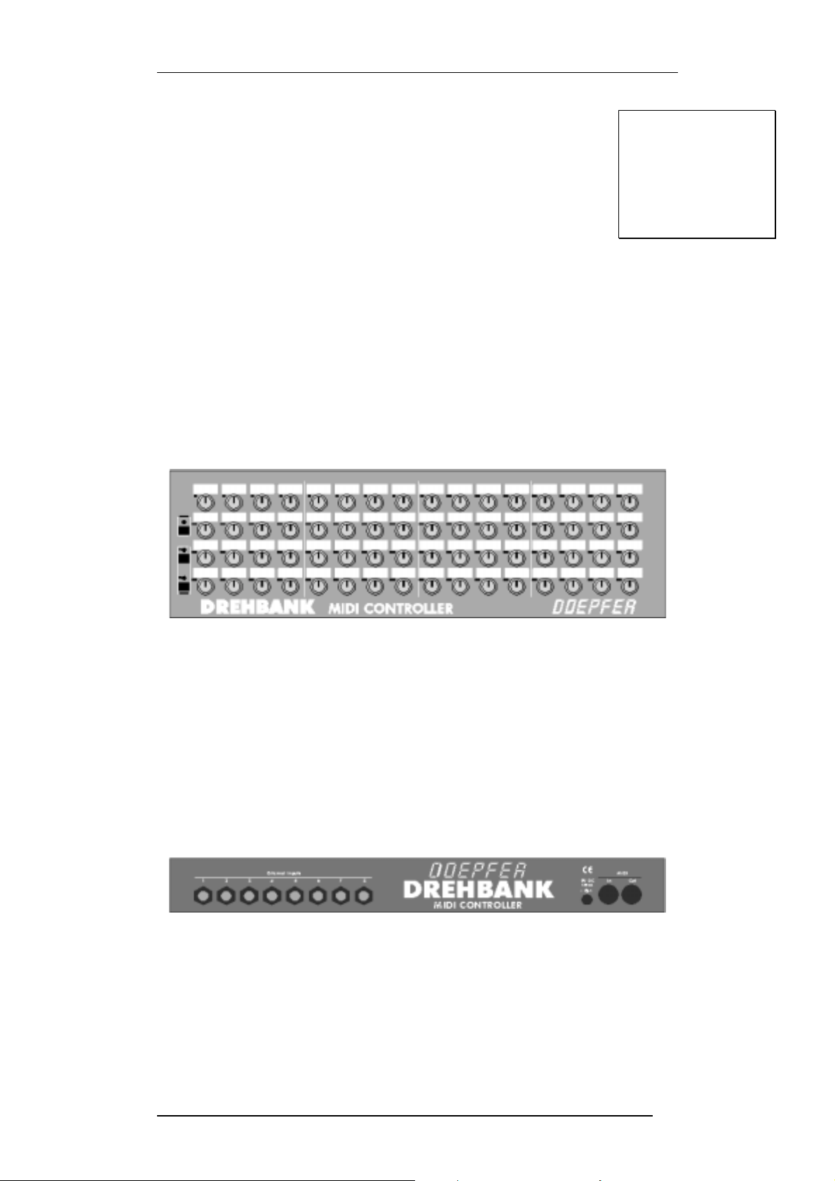
The jack, through which the control volt age is transmitted, must be c onfigured as
follows:
Control voltage (CV)
Unused (N.C.)
Ground (GND)
Jack configuration
for cv mode
You can also use a mono jack (pin hot).
In the default settin gs, the external inp uts 1, 2, 3, 4 corres pond with th e controller
knobs 31, 15, 47, 63 and are set for control voltage mode.
When the supplied co ntrol v oltag e does not c over the com plete v oltag e ran ge f rom
0...+5V the full Midi data range is not available. In this case the range of the
corresponding control k nob may be adjusted by altering th e settings for the lower
and upper reference voltage of the ADC (analog digital converter). See !MAIN
EDITOR Window (Edit Control: ADC_REF and ADC _G ND)
Foot controller Oper ation
When a foot controller is connected to the external input it does not supply a
control voltage but repr esents a v ariable r esistor (v oltage di visor or potentiom eter).
The Drehbank sends a fixed contro l voltage of +5 V to the input ( connected t o the
ring of the ¼" jack ), so the potentiometer inside the foot contr oller can gener ate a
variable control volta ge going back to the Drehbank (connected to th e t ip of th e ¼"
jack, same as in CV mode). The required potentiometer needs to have 3
connections: low position, middle position (wiper), and high position. The
potentiometer in the foot contr oller should have a total resistance within the range
between 5k...25k. Some foot controllers are fitted with potentiometers that have
only 2 connections, these cannot be used with Drehbank.
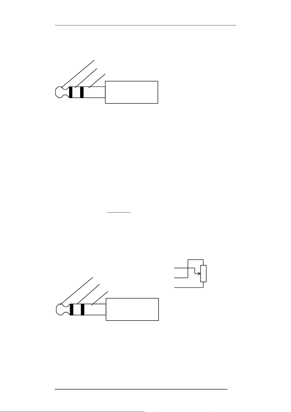
When working with a foot controller the stereo jack must be configurated as
follows,
Middle position (CV)
High position (= +5V)
Low position (GND)
Jack configuration
for fc mode
Be careful as to which foot contro ller you buy, m ake sure that it is compatible with
the Drehbank. We recomm end the Doepfer FP5/DB f oot c ontro ll er (s pec ia l ver sio n
for the Drehbank, the FP5 version use d with our keyboards is not c ompatible as
the jack connection is different !).
36
36
3636
Page 36

APPENDIX
In the default settin gs of the D rehbank the ex ternal inputs 5, 6, 7 , 8 corres ponding
with the controller knobs 32, 48, 16, 64 are set for foot controller mode.
When a foot controller does not supply a control voltage covering the complete
control voltage range from 0...+5V the full MID I data range is no t available. In this
case the range of the correspond ing control knob must be adjus ted (same as for
CV mode).
If desired the operation modes of the 8 external inputs c an be redefin ed (e.g. all 8
inputs redefined as foot contro llers or CV inputs). This should o nly be done by a
Doepfer
authorised Service-dealer or directly by
warranty. The same goes for the ins tallation of the CV option, i.e. if the Drehbank
does not contain the CV option and this option has to be installed later.
If you then still want to modif y the unit yourself in any wa y despite our warning we
will send you the D rehbank ser vic e manual for a sm all f ee. The correct proce dur es
are listed in this manual. Simply send us DM 20 (or 10 Euro) with the serial
number of the Drehbank or a copy of your purchase receipt.
The Address is Doepfer Musikelektronik GmbH, Geigerstr.13, D-82166,
Graefelfing, Germany. The manual will also be available on our internet site
http://www.doepfer.com.
Doepfer
DoepferDoepfer
, so as not to loose your
37
37
3737
Page 37

APPENDIX
Bibliography
This bibliography is subjective, and not guaranteed 100% accurate !
The most-up-to-date printed specs for General MIDI, MIDI, and the MIDI
file format can be obtained for a few bucks from:
International MIDI Association
23634 Emelita Street
Woodland Hills, Califor nia 913 67 USA
Steve De Furia & Joe Scacciaferro,
"MIDI Programmer's Handbook"
M&T Books
ISBN 1-55851-068-0
Michael Cxelperger: "Introducing Standard MIDI File".
Electronic Musican,
April 1989, S. 50ff
Title: "Computer music in C" / Phil Winsor & Gene DeLisa.
Publisher: Blue Ridge Summit, PA : TAB Books (Windcrest label), c1991.
Subjects:
Computer sound processing.
Computer composition.
C (Computer program language)
Midi programming
ISBN: 0-8306-3637-4 (p) : $22.95
It has a C source disk for the PC available for $25.
Title: "Mind over MIDI" / edited by Dominic Milano by the editors of Keyboard
magazine.
Publisher: Milwaukee, WI : H. Leonard Books, c1987.
Series Name: The Keyboard magazine basic library
Other Series Names: Keyboard synthesizer library.
Subjects:
MIDI (Standard)
Computer sound processing.
ISBN: 0-88188-551-7 (pbk.) : $12.95
The book consists mostly of reprints of KEYBOARD magazine articles
from the early-mid '80s plus several appendixes containing the
MIDI 1.0 specification, a list of references, a glossary, etc.
"Atari ST Introduction to MIDI Programming"
Len Dorfman and Dennis Young
ISBN 0-916439-77-1
Bantam Books,Inc.
666 5th Avenue
New York,New York
10103
Title:"Music through MIDI : using MIDI to create your own electronic music
system" / Michael Boom.
Publisher: Redmond, Wash. : Microsoft Press, c1987.
Subjects:
MIDI (Standard)
Musical instruments, Electronic.
Electronic music--Instruction and study.
Computer sound processing.
ISBN: 1-55615-026-1 (pbk.) : $19.95
38
38
3838
Page 38

APPENDIX
Title:"The MIDI drummer : by a drummer for a drummer" / by David Crigger.
Publisher: Newbury Park, CA : Alexander Pub., c1987.
Subjects:
Electronic percussion instruments--Instruction and study.
MIDI (Standard)
Title: "MIDI for musicians" / by Craig Anderton.
Publisher: New York : Amsco Publications, c1986.
Subjects:
MIDI (Standard)
Computer sound processing.
ISBN: 0-8256-1050-8 (pbk.)
ISBN: 0-8256-2214-X (pbk. : cover)
Title: "The MIDI manual" / David Miles Huber.
Publisher: Carmel, Ind., USA : Howard W. Sams, c1991.
ISBN: 0-672-22757-6, 250pp.
Title: "The MIDI programmer's handbook" / Steve De Furia and Joe
Scacciaferro, Ferro Technologies.
Publisher: Redwood City, Calif. : M&T Pub., c1989.
ISBN: 1-55851-068-0, 250 pp. Paperback. $24.95 Mix Bookshelf part # 3539C
Title: "C Programming for MIDI" / Jim Conger.
Publisher: Redwood City, Calif. : M&T Books, 1989.
501 Galveston Drive Redwood City, CA 94063
Subjects: MIDI, C, sequencing
This book shows how to use the basic features of an MPU-401 interface.
Includes a disk with MS-DOS code.
Title: "MIDI sequencing in C" / Jim Conger.
Publisher: Redwo od C ity, Calif. : M&T Bo ok s , 1989. 5 01 G a lv es ton Drive Redw ood
City, CA 94063
Subjects:
MIDI (Standard)
C (Computer program language)
Sequential processing (Computer science)
ISBN: 1-55851-045-1 (book) : $24.95
ISBN: 1-55851-047-8 (disk) : $20.00
ISBN: 1-55851-046-X (set) : $39.95This book continues where the provious one
lefts off.
39
39
3939
Page 39

CCHHAAPPTTEERR 5
5
AAPPPPEENNDDIIX
X
40
40
4040
 Loading...