

Page 1
DIAL
ELECTRONIC
Universal Midi Control Electronics for rotary encoders
Installation and User's Guide
© 2005 by Doepfer Musikelektronik
Page 2

Electrical safety / EMC compatibility
DIAL ELECTRONIC
(OEM original equipment manufacturer) that cannot be used independently but has to
be combined with additional electrical or electronical equipment to become a working
device (e.g. rotary encoders, switches, LEDs, power supply, case/housing). The
manufacturer of DE does not know the final assembly of the complete device in
which the
regard to
is assembling the complete device.
Electronic basic knowledge is required to install DE and to connect the rotary
encoders, switches and LEDs.
sufficient please consult an expert. We cannot take back modules that became
defective because of wrong installation or wrong connection of the controls.
Please pay attention to the following items:
The
power supply
Germany a power supply with VDE approval is required). Normally an AC adapter
with plastic case is used. It is not allowed to use
mains voltage
On the DE
filters at the power supply input and the Midi lines). But it is impossible to estimate to
what extend the
complete assembly. Therefore the
electromagnetic radiation
met by a closed metal case that covers the complete assembly. The metal case
should be connected to GND of the DE.
is used as a part of the complete device. The final responsibility with
DE
electrical safety
preventing measures
(abbreviated "DE" in the following) is a so-called
and
electromagnetic compatibility
If you are not sure whether your knowledge is
used in combination with the DE has to be a closed type (in
open power supplies
access (e.g. via mains lead, pcb tracks, electronic parts).
against
components added by the user
complete device
(incoming and outgoing). These demands are normally
electromagnetic radiation
affect the
has to be
is up to the user who
EMC properties
shielded
OEM product
are taken (RF
whith open
of the
against
Warranty
Do not solder directly to any of the pin headers but use female connectors to
•
make the connections between DE and the rotary encoders, switches and LEDs.
A cable set that contains all required connectors and cables is included with DE.
Carry out all connections in the off-state of DE (i.e. when powered-off only) !
•
Do not connect any voltage to the pin headers but only the encoders, switches
•
and LEDs as described in this manual.
• DE
•
•
•
electronics is an electrostatic sensitive device. Avoid any electrostatic charges
!
Avoid short circuits !
Ignoring any of these items will cause warranty loss !
Return of the DE within the 2 weeks return time limit (valid only in Germany) is
only possible if all these items have been met. Return of used cable sets is not
possible. We also cannot take back modules that have been soldered by the user.
DIAL ELECTRONIC Page 2 User's Guide
Page 3

Table of contents
Electrical safety / EMC compatibility ........................................................................................2
Warranty...................................................................................................................................2
Table of contents......................................................................................................................3
Introduction...............................................................................................................................4
Connections .............................................................................................................................5
Power Supply (1) ..................................................................................................................6
Midi Out Socket (2) ...............................................................................................................6
Midi In Socket (3)..................................................................................................................6
Connectors for the 16 rotary encoders (4)............................................................................7
Connector for 6 control switches (5) .....................................................................................8
Connector for 4 LEDs (6)......................................................................................................8
DIP Switches (7) ...................................................................................................................9
Check list................................................................................................................................10
Mounting.................................................................................................................................10
Extent of delivery....................................................................................................................11
User's Guide Page 3 DIAL ELECTRONIC
Page 4

Introduction
• Dial Electronic
DIY kit to built your own MIDI control box with 16 rotary encoders (even called
alpha dials, endless potentiometers or similar).
• DE
• DE
• DE
•
•
•
• DE
•
•
•
•
• DE
generates 16 different MIDI messages on different (or even the same) MIDI
channels. The available Midi messages are described in the Pocket Dial manual.
The most important messages are probably the Midi Control Change messages –
often simply called "Midi controllers". In the following we are sometimes talking
about Midi controllers though other Midi messages are possible.
can be combined with the MKE, Pocket Electronic, CTM64 or MTC64 to
obtain a unique controller that fits exactly to the user's requirements.
essentially contains the same electronics as
rotary encoders, switches and LEDs. Concerning the Midi functions
identical to Pocket Dial. Therefore the user's manual of Pocket Dial is part of the
delivery. The basic functions of DE and the programming of the Midi functions
DE
is described in the Pocket Dial manual.
This manual describes only the connections of the controls (rotary encoders,
switches, LEDs) to DE.
The controls (rotary encoders, switches, LEDs) are not included but have to be
added by the customer. We offer a suitable control set (16 encoders with black
knobs, 6 buttons, 4 LEDs, cables) that has to be purchased separately.
The 16 rotary encoders are connected to 16 single row pin headers with 3 pins
each. The switches are connected to a double row pinheader with 16 pins. The
LEDs are connected to a double row pinheader with 10 pins. To these headers
suitable ribbon cables (with 3/10/16 pins) are put up. The terminals of the
encoders, switches and LEDs are soldered to the free ends of the ribbon cables.
In this way the controls might be disconnected from the electronics very easily.
is equipped with Midi In and Midi Out. The incoming Midi messages are
merged to the data generated by DE. In this way several DE can be linked
together to obtain larger controller arrays with more than 16 controls or can be
combined with other OEM products like Pocket Electronic, CTM64, MKE and
similar.
The DE configuration (i.e. the assignment of Midi messages and channels to the
controls in the 128 presets) is made with an editor program (PC version, free
download from our web site www.doepfer.com). It enables the user to program his
own 128 presets. The OEM version of Emagic's Sounddiver is available too (extra
charge).
The factory presets are described in the the Pocket Dial manual. These can be
changed with the editor program.
An external power supply (7-12VDC@min. 100mA) is required for the DE. It is
included for all shipments within Germany (230V version with European mains
plug). For shipments outside Germany please ask your local representative or
dealer.
We do not offer a suitable housing as this would have to be completely different
for various combinations of controls.
is available only as an assembled and tested pc board (about 125 x 70 x 25
mm). Six mounting holes with 3 mm diameter are available for mounting the pc
board to a suitable base e.g. with distance sleeves or spacers and screws.
(abbreviation: "DE" in the following) is an universal electronics
Pocket Dial
but without the 16
is 100%
DE
DIAL ELECTRONIC Page 4 User's Guide
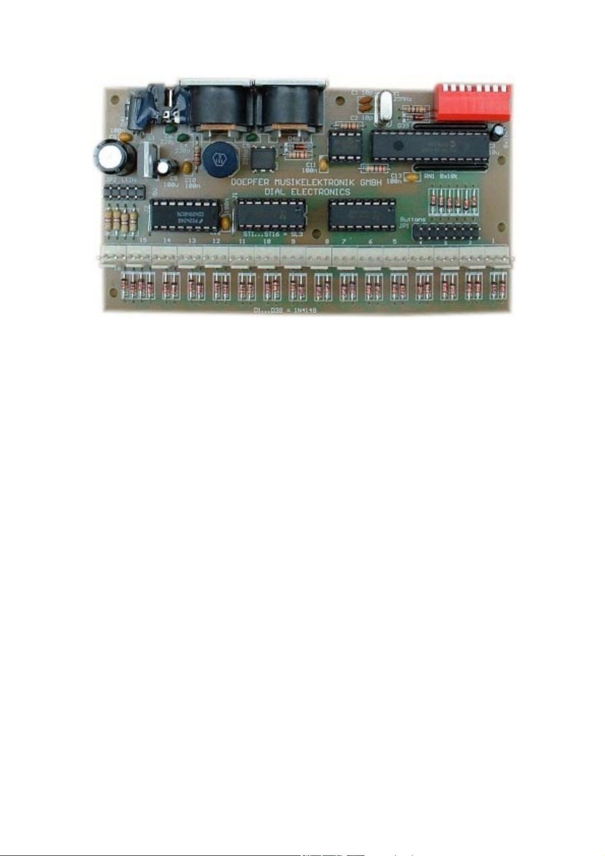
Page 5

Connections
(7)
DIP switch
used to select one of
the presets
8 = uppermost switch
1 = lowest switch
(5)
connector for the
switches / buttons
(JP1)
(4)
connectors for 16 rotary encoders
(ST1...ST16)
(3)
Midi In
(BU1)
(2)
Midi Out
(BU2)
(1)
power supply
7-12V / 100mA DC
(BU3)
(6)
connector for the
LEDs
(JP2)
User's Guide Page 5 DIAL ELECTRONIC
Page 6

Power Supply (1)
does not have a built-in power supply. Instead it uses a plug-in type external
DE
power supply (AC adapter). One reason for this feature is electrical safety. Keeping
danger voltages (main) out of the DE increases the electrical safety. Therefore an
external power supply of high quality and safety should be used. If DE is used in
Germany the external power supply has to be VDE approved. Another reason for the
external power supply is the fact that mains voltages and plug types vary
considerably from country to country. Using a plug-in external supply DE can be used
any where with a locally purchased power supply, thus keeping the retail price down.
The power supply has to be able to deliver 7-12 V unstabilized DC voltage, as well as
a minimum current of 100mA. DE is switched ON by plugging the AC adapter into a
wall outlet and connecting it to the appropriate jack on the DE board. There is no
separate on/off switch. If the polarity of the power supply is incorrect, DE will not
function. However, there is no danger of damage to the circuitry since it is protected
by a diode. The correct polarity is: outside ring = GND, inside lead = +7...12V. A
power supply for 230V mains voltage with European type mains plug is included with
the
(valid only within Europe, for other countries ask you local Doepfer
DE
representative or dealer).
Midi Out Socket (2)
Connect the Midi Out socket with Midi In of the device to be controlled by DE (e.g.
Computer, Synthesizer, second daisy-chained DE or another OEM/DIY product like
MKE, CTM64, Pocket Electronic) via a suitable Midi cable. If you want to control
more than one Midi device you have to use daisy chain Midi Thru / Midi In connection
of the devices ore use a external Midi Thru box.
Midi In Socket (3)
The
features a Midi input. This input may be connected to another Midi device
DE
(e.g. Midi keyboard). The incoming Midi data are merged to the data generated by
. The Midi input may be used as well for daisy-chaining several DE. The Midi input
DE
of DE is not suitable for large amounts of Midi data (e.g. SysEx strings or Midi
messages coming from an computer sequencer) as the DE has only a small Midi in
buffer. In case of large amounts of incoming Midi data loss or delay of data may
occur.
The Midi input is also required when DE is programmed with the editor software. In
this case the Midi input of DE has to be connected to the Midi output of the computer
on which the editor program is running. The Midi output of DE has to be connected to
the Midi input of the computer. Details can be found in the Pocket Dial manual and
the manual of the editor program.
Even if DE is used to generate absolute Midi control change messages with data
update/feedback from the device controlled by DE the Midi In of DE has to be
connected to Midi Out of the device in question. Details about this mode are available
in the Pocket Dial user's manual.
If none of the applications described above is used the Midi input is left open.
DIAL ELECTRONIC Page 6 User's Guide
Page 7

Connectors for the 16 rotary encoders (4)
For the connection of 16 rotary encoders the 16 single row pin headers ST1...ST16
(3 pins each) are available.
A rotary encoder has three terminals available: common terminal, output 1 and output
2. When operating the encoder the outputs 1 and 2 are shortened to the common
terminal in a certain sequence (different for right and left rotation). In the end an
encoder is nothing but two switches with one common terminal. The DE decodes this
switching sequence and generates the corresponding Midi messages.
The lower pin of each pin header (refer to the picture on page 6) corresponds to the
common termincal of the encoder. The other two pins correspond to the (active)
switches of the encoders. Please look into the data sheet of the encoder used to find
out the pin assignment of your encoder. If the two active terminals are mixed up the
Midi function is reverse. We recommend to connect only one encoder at first to find
out the correct polarity before the other encoders are connected. If the terminals are
connected in the wrong way nothing can be damaged but the encoder will not work
correctly (i.e. no function or reverse).
If ALPS encoders EC16B24 are used the order of the three pins matches to the pin
headers of the DE. These encoders are available as single spare parts or as a
complete control set for DE (16 encoders with black knobs, 6 buttons, 4 LEDs,
cables) that has to be purchased separately.
Suitable 3-pin female connectors with cables can be used to connect the encoders to
the pin headers ST1...ST16 instead of soldering the cables directly to the pin
headers. We strictly recommend this type of wiring but not to solder the wires directly
to the pin headers. Usage of cables with female connectors allows to disconnect the
encoders from the electronics very easily. Suitable female connectors with cables are
available as single spare parts and are even included with the control set for DE.
Unused encoder connectors are left open (no termination required).
Remark (only if the Dial Electronics control set is used):
The measure of the 3 pin female connector of the cable sets is a little bit more than
the corresponding pin header on the pc board. Consequently the female connectors
have to be grinded off a bit (e.g. with sandpaper). Otherwise several female
connectors will not fit side by side.
User's Guide Page 7 DIAL ELECTRONIC
Page 8

Connector for 6 control switches (5)
The pin header JP1 is used to connect 6 control switches (momentary switches,
buttons). This is the pin out of JP1 (refer to the picture on page 6):
T1a T1b
Each of the 6 switches (labelled T1 ... T6) has two terminals (a
and b) that have to be connected to the corresponding pins of
the pin header. The first switch has to be connected to the pins
T2a T2b
T1a and T1b, the second to T2a and T2b and so on. Simple
momentary switches (open at rest) are used.
T3a T3b
The 4 lower pins are not used (NC = not connected).
T4a T4b
We recommed the usage of a 16 pin female connector with 16
T5a T5b
pin ribbon for this connection. The switches are soldered to the
open ends of the ribbon cable. The female connector with
ribbon cable is included with the DE control set.
T6a T6b
NC NC
NC NC
Connector for 4 LEDs (6)
The pin header JP2 is used to connect 4 LEDs. This is the pin out of JP2 (refer to the
picture on page 6):
Each LED has two terminals: + (positive terminal or anode) and
– (negative terminal of cathode). The shortened LED pin is
NC NC
normally the cathode. Each of the 4 LEDs is connected to the
corresponding pins Lx+ (positive LED terminal) and Lx-
L1+ L1-
(negative LED terminal). The first LED is connected to L1+ and
L1-, the second to L2+ and L2- and so on. Almost each LED
L2+ L2-
type can be used (3mm / 5mm / rectangle, red / orange / yellow
/ green / blue / white).
L3+ L3-
L4+ L4-
The two upper pins of JP2 are not used (NC = not connected).
We recommed the usage of a 10 pin female connector with 10
pin ribbon for this connection. The LEDs are soldered to the
open ends of the ribbon cable. The female connector with
ribbon cable is included with the DE control set.
DIAL ELECTRONIC Page 8 User's Guide
Page 9

It has to be pointed out that we cannot take back DE modules with solder residues on
the pin headers ! Therefore we recommed the usage of female for the encoders,
switches and LEDs.
The functions of the switches and LEDs is the same as for Pocket Dial. Please refer
to the Pocket Dial manual that is included with the DE delivery.
DIP Switches (7)
The positions of the 8 switches of SW1 (7) determine the number of the preset that is
called up during power on. Up to 128 different presets are available. If none of the
factory presets can be used the editor program enables the user to program his own
presets.
The function of the DIP switches and the connection between the position of the
switches and the preset number is described in the Pocket Dial manual.
Pay attention to the numbering of the 8 switches in the picture on page 5. The
numbering printed to the DIP switch may differ from this numbering. Please use only
the numbering of the switches in this manual to select a preset !
User's Guide Page 9 DIAL ELECTRONIC
Page 10

Check list
In case that your DE installation does not work at the first go please check the
following points:
Is the power supply working correctly ? Provided that the 4 LEDs are connected to
•
JP2 they have to light up one after the other and then LED #1 has to light up only.
Are the controls (encoders, switches, LEDs) connected as described in this
•
manual ?
Was no short circuit made (neither in the wiring nor mounting) ?
•
When the diode D41 and the voltage regulator IC7 become hot probably a short
•
circuit between GND and +5V was made !
Are the Midi connections between DE and the other Midi devices installed correctly
•
? Midi Out of DE has to be connected to Midi In of the Midi device controlled by
. Especially when computers are used Midi In and Out are very often mixed up
DE
by the user. Once again: Midi Out → Midi In (not Midi Out → Midi Out nor Midi In
Midi In).
→
Please use only cables that are suitable for Midi.
•
When a PC with sound card is used only high quality multimedia cables should be
•
used. Low cost multimedia cables without optocouplers for Midi In and without
drivers for Midi Out very often cause Midi data problems.
Is the right preset number selected with the DIP switch ? A good preset number for
•
testing is no 1: if 8 switches are "off" one obtains volume on the Midi channels
1...16 (provided that the factory presets are unchanged, otherwise the Midi
messages you have programmed to preset no 1 will appear).
Mounting
Before DE is put into operation the board has to be fixed on a suitable support and
built into a metal case together with the controls (refer to EMC notes on page 2). The
metal case has to be connected to GND of
plate of the voltage regulator 7805/IC7 or the GND terminal of the power supply
socket for this connection.
Several mounting holes with 3 mm diameter are available for mounting the board
inside the case e.g. with distance sleeves or spacers (> 5 mm in length) and suitable
screws. Pay attention that no short circuits are made – neither on the top of the board
(electronic parts) nor on the bottom (solder points or pcb tracks). In case of doubt
use isolating plastic parts (e.g. plastic screws, nuts and washers) for mounting.
We recommend to use the metal
DE.
DIAL ELECTRONIC Page 10 User's Guide
Page 11

Extent of delivery
The DE delivery contains the following parts:
Dial Electronic pc board, assembled and tested
•
Power Supply (230V mains voltage, European type mains plug, output voltage
•
range 7...12V, current min. 100 mA) included only for shipments within Germany,
for shipments outside Germany please contact your local representative or dealer
Dial Electronic user's guide (i.e. the guide in your hand)
•
Pocket Dial user's guide
•
Rotary encoders, switches, LEDs and cables are not included but have to be added
by the customer. We offer a suitable control set (16 encoders with black knobs, 6
buttons, 4 LEDs, cables) that has to be purchased separately.
The DE control set contains the following parts:
16 rotary encoders (ALPS EC16B24)
•
16 black rotary knobs (same as used for Pocket Dial)
•
16 cable sets with female connectors for the encoders
•
6 momentary switches (round, with thread for mouting into a front panel)
•
one 16 pin ribbon cable with 16 pin female connector, about 30 cm (for wiring the
•
switches to JP1)
4 LEDs (red, 3 mm)
•
one 10 pin ribbon cable with 10 pin female connector, about 30 cm (for wiring the
•
LEDs to JP2)
Remark:
The measure of the 3 pin female connector of the cable sets is a little bit more than
the corresponding pin header on the pc board. Consequently the female connectors
have to be grinded off a bit (e.g. with sandpaper). Otherwise several female
connectors will not fit side by side.
User's Guide Page 11 DIAL ELECTRONIC
Page 12

Doepfer
Musikelektronik
www.doepfer.com
DIAL ELECTRONIC Page 12 User's Guide
 Loading...