

Doepfer Dark Energy III Additional technical information

DOEPFER MUSIKELEKTRONIK GMBH
DARK ENERGY III
Additional technical information
The instructions collected in this document are intended only for experienced users who want to modify or
expand the functions of Dark Energy III. For some of the modifications/expansions the warranty may be
void ! Therefore we recommend to ask an authorized Doepfer service partner to carry out the
modifications. Any damage (mechanical or electrical) caused by inappropriate handling is not covered by
warranty and treated as a repair liable to pay costs.
Mechanical connection of several Dark Energy's (I / II / III)
Two or more Dark Energy's can be mounted together in two ways:
• with wooden side plates between the units
• without wooden side plates between the units
Procedure:
• Remove the bottom cover of the Dark Energy (four crosshead screws at the edges, screw #5 is just
used to fix the Midi socket).
• Remove the interface board by solving the 5 nuts of the jack sockets at the rear panel
• Remove the right side plate of Dark Energy #1 and the left side plate of Dark Energy #2 by loosening
of the two screws that are used to hold the side plates. Attention ! A suitable short or angled Philips
screwdriver is required ! A long screw driver may damage the screws because of the angle between
screw and screwdriver.
• If the two Dark Energy have to be mounted together without side plate between the units the two
metal cases are mounted together with suitable screws, nuts and washers (e.g. M3x10 screws). For
this the holes are used which were used before to mount the side plates.
• If the two Dark Energy have to be mounted together with a wooden side plate between the units one
of the disassembled side plates has to be modified: the two small holes have to be drilled up (e.g. by
means of a drill with 3-3.5 mm diameter). In addition a larger hole (about 7 mm diameter) may be
drilled if the two units have to be linked via Midi out/in (see next paragraph). The position of this
additional hole has to be in line with the position of the large hole in the black metal case. Then the
two Dark Energy and the wooden side plate are mounted together by suitable screws, nuts and
washers (e.g. M3x20-25 screws). For this the holes are used which were used before to mount the
side plates.
• Re-install the interface board and mount the bottom cover.
Linking of several Dark Energy's (I / II / III) via Midi Out/Midi In
Unfortunately there was not sufficient space for a Midi out socket at the rear panel. But it's possible to link
two or more Dark Energy's internally via Midi out/Midi in. For this two pin headers (JP5 and JP6) are
available at the supply/interface board (that's the board mounted at the rear panel). They are located on
top and bottom of the Midi optocoupler PC900. JP5 is the Midi output, JP6 the Midi input. The left pin of
both pin headers is GND, the right pin is the "hot" pin (i.e. Midi in or Midi out).
To connect two Dark Energy's via Midi JP5 of the first unit has to be wired to JP6 of the second unit. A
suitable link cable is available soon. Pay attention to the correct polarity of the cables (GND Æ GND and
hot pin Æ hot pin). If the polarity is wrong nothing can be damaged but the link function will not work. The
link cable is fed trough the holes in the side plates of the case. If a wooden side plate is used between the
two units the side plate has to be drilled in addition.
Pay attention that the first unit has to be programmed for stack mode . Details in the user's guide.
A suitable link cable is enclosed to each Dark Energy (2 wire cable with black and red wire and a female 2
pin connector on both sides).
DARK ENERGY III - Additional Technical Information – Page 1
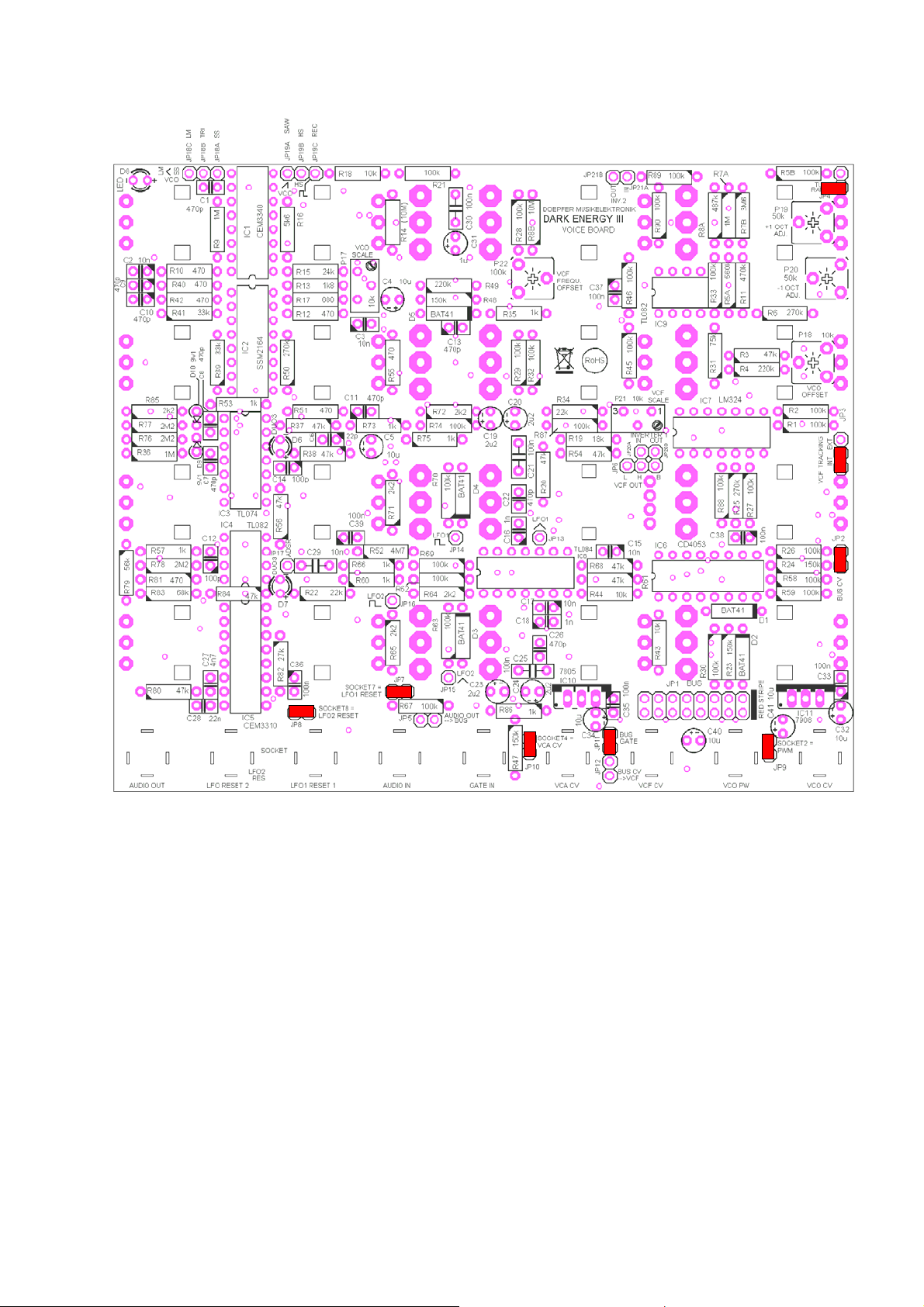
Position and Function of the Jumpers and trimming potentiometers
Voice Board Dark Energy III
DARK ENERGY III - Additional Technical Information – Page 2
 Loading...