

Dodge WipersWashers 3500 2005, WipersWashers 2500 2005, WipersWashers 1500 2005 Service Manual
Page 1

DR/DH WIPERS/WASHERS 8R - 1
WIPERS/WASHERS
TABLE OF CONTENTS
page page
WIPERS/WASHERS - ELECTRICAL
DIAGNOSTICS ........................... 1
WIPERS/WASHERS - ELECTRICAL DIAGNOSTICS
TABLE OF CONTENTS
WIPERS/WASHERS - ELECTRICAL
DIAGNOSTICS
DIAGNOSIS AND TESTING
FCM-WASHER FLUID LEVEL SENSOR
CIRCUIT FAILURE ......................2
FCM-WASHER PUMP OUTPUT CIRCUIT
LOW ................................6
FCM-WASHER PUMP OUTPUT CIRCUIT
OPEN ...............................9
FCM-WIPER ON-OFF RELAY OUTPUT
CIRCUIT HIGH ........................13
FCM-WIPER ON-OFF RELAY OUTPUT
CIRCUIT OPEN .......................16
FCM-WIPER ON-OFF RELAY OUTPUT
CIRCUIT LOW ........................19
WIPERS/WASHERS - SERVICE INFORMATION .. 45
page page
FCM-WIPER PARK SWITCH INPUT
PERFORMANCE ......................22
FCM-WIPER SPEED RELAY OUTPUT
CIRCUIT HIGH ........................26
FCM-WIPER SPEED RELAY OUTPUT
CIRCUIT LOW ........................29
FCM-WIPER SPEED RELAY OUTPUT
CIRCUIT OPEN .......................32
MIC-WASH-BEAM INPUT CIRCUIT
SHORTED ...........................35
MIC-WIPER SWITCH INPUT CIRCUIT OPEN . 38
MIC-WIPER SWITCH INPUT CIRCUIT
SHORTED ...........................41
SCHEMATICS AND DIAGRAMS ............44
WIPERS/WASHERS - ELECTRICAL DIAGNOSTICS
DIAGNOSIS AND TESTING
Page 2
8R - 2 WIPERS/WASHERS - ELECTRICAL DIAGNOSTICS DR/DH
FCM-WASHER FLUID LEVEL SENSOR CIRCUIT FAILURE
Page 3
DR/DH WIPERS/WASHERS - ELECTRICAL DIAGNOSTICS 8R - 3
FCM-WASHER FLUID LEVEL SENSOR CIRCUIT FAILURE (CONTINUED)
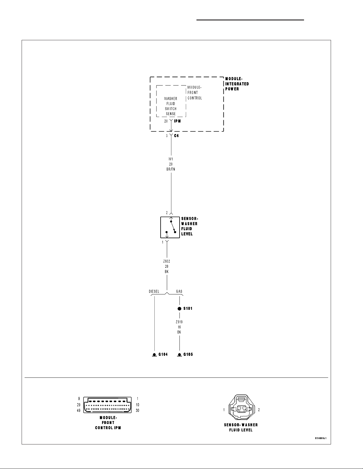
For the Wiper Washer system circuit diagram (Refer to 8 - ELECTRICAL/WIPERS/WASHERS - SCHEMATICS AND
DIAGRAMS).
For a complete wiring diagram Refer to Section 8W.
• When Monitored:
Continuous with the ignition on.
• Set Condition:
The FCM detects the Washer Fluid Level Switch circuit voltage is below 0.05 volts or above 5.0 volts.
Possible Causes
WASHER FLUID LEVEL SWITCH
WASHER FLUID LEVEL SENSOR SIGNAL CIRCUIT OPEN
WASHER FLUID LEVEL SWITCH GROUND CIRCUIT OPEN
WASHER FLUID LEVEL SWITCH SIGNAL CIRCUIT SHORT TO GROUND
FRONT CONTROL MODULE
Diagnostic Test
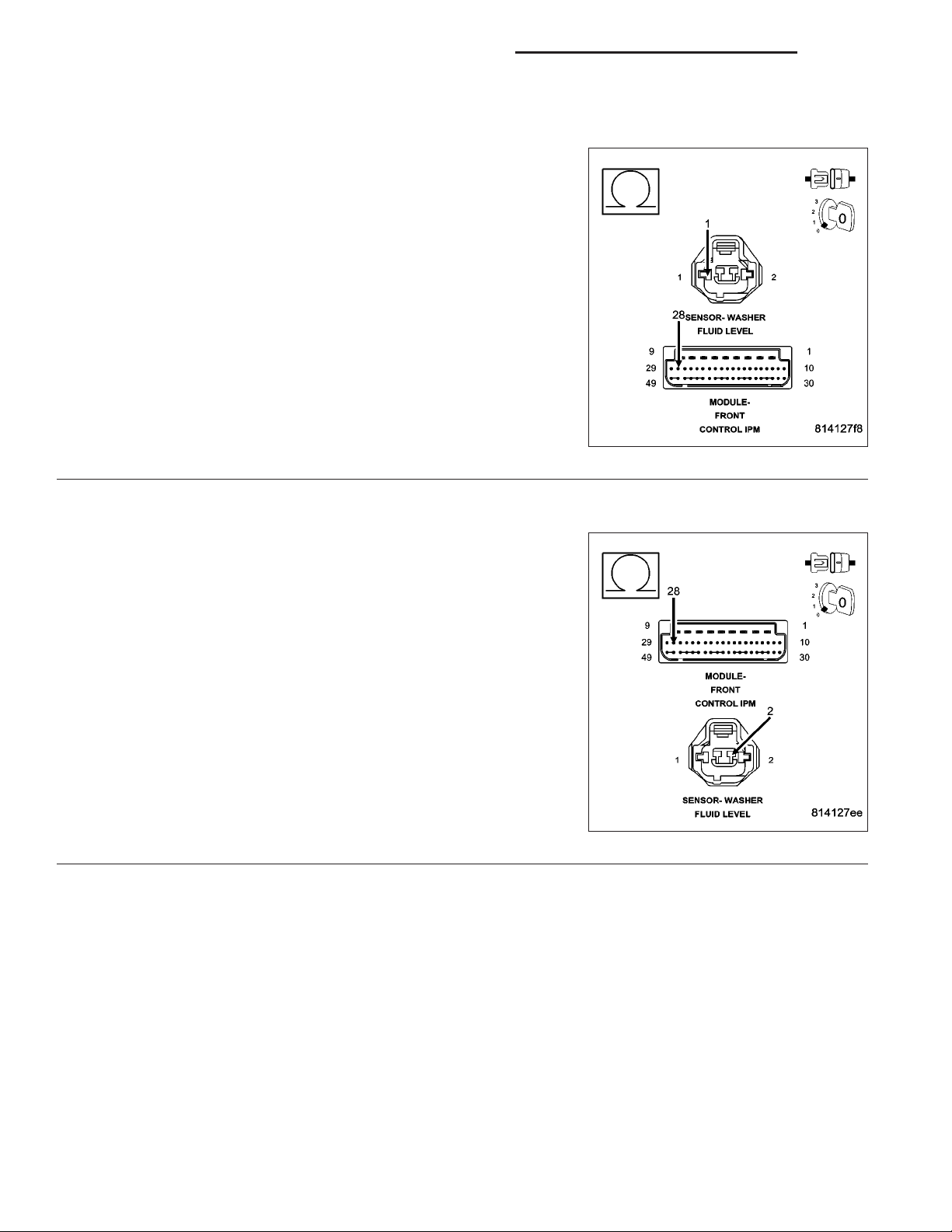
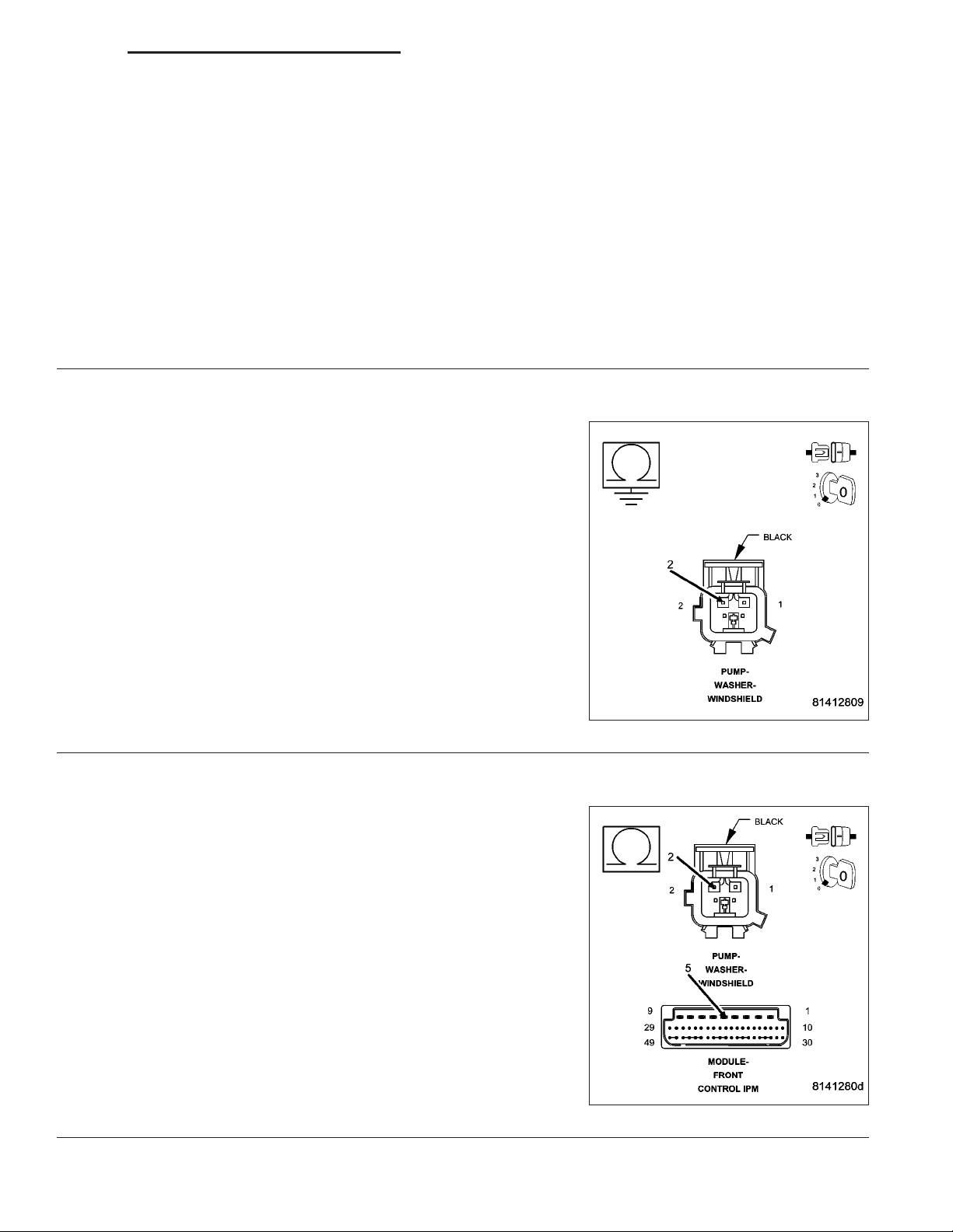
WASHER FLUID LEVEL SWITCH
1.
Turn the ignition off.
Disconnect the Washer Fluid Level Switch harness
connector.
Connect a jumper wire between cavity 1 and cavity
2.
With the DRBIIIT, in Sensors, read the Washer
Fluid Level Switch Volts.
Does the DRBIIIT read below 1 volt?
Yes >>
No >>
Replace the Washer Fluid Level Switch
in accordance with the Service Information.
Perform BODY VERIFICATION TEST VER 1.
Go To 2
Page 4
8R - 4 WIPERS/WASHERS - ELECTRICAL DIAGNOSTICS DR/DH
FCM-WASHER FLUID LEVEL SENSOR CIRCUIT FAILURE (CONTINUED)
WASHER FLUID LEVEL SWITCH SIGNAL CIRCUIT OPEN
2.
Turn the ignition off.
Disconnect the FCM harness connector.
Disconnect the Washer Fluid Level Switch harness connector.
Measure the resistance of the Washer Fluid Level Switch Signal cir-
cuit.
Is the resistance above 5.0 ohms?
Yes >>
No >>
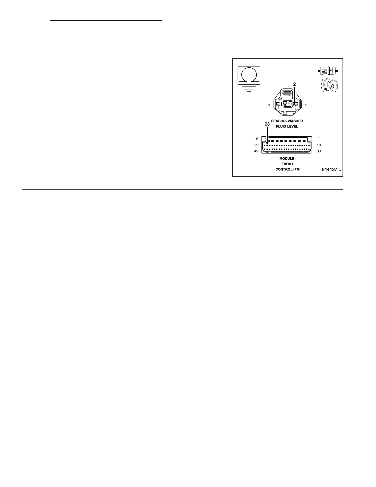
WASHER FLUID LEVEL SWITCH GROUND CIRCUIT OPEN
3.
Turn the ignition off.
Disconnect the FCM harness connector.
Disconnect the Washer Fluid Level Switch harness connector.
Measure the resistance of the Washer Fluid Level Switch Ground cir-
cuit.
Is the resistance above 5.0 ohms?
Yes >>
No >>
Repair the Washer Fluid Level Sensor Signal circuit for an
open.
Perform BODY VERIFICATION TEST - VER 1.
Go To 3
Repair the Washer Fluid Level Switch Ground circuit for an
open.
Perform BODY VERIFICATION TEST - VER 1.
Go To 4
Page 5
DR/DH WIPERS/WASHERS - ELECTRICAL DIAGNOSTICS 8R - 5
FCM-WASHER FLUID LEVEL SENSOR CIRCUIT FAILURE (CONTINUED)
WASHER FLUID LEVEL SWITCH SIGNAL CIRCUIT SHORT TO GROUND
4.
Turn the ignition off.
Disconnect the FCM harness connector.
Disconnect the Washer Fluid Level Switch harness connector.
Measure the resistance between ground and the Washer Fluid Level
Switch Signal circuit.
Is the resistance below 5.0 ohms?
Yes >>
No >>
Repair the Washer Fluid Level Switch Signal circuit for a
short to ground.
Perform BODY VERIFICATION TEST - VER 1.
Replace the Front Control Module (FCM) in accordance
with the Service Information.
Perform BODY VERIFICATION TEST - VER 1.
Page 6
8R - 6 WIPERS/WASHERS - ELECTRICAL DIAGNOSTICS DR/DH
FCM-WASHER PUMP OUTPUT CIRCUIT LOW
Page 7
DR/DH WIPERS/WASHERS - ELECTRICAL DIAGNOSTICS 8R - 7
FCM-WASHER PUMP OUTPUT CIRCUIT LOW (CONTINUED)
For the Wiper Washer system circuit diagram (Refer to 8 - ELECTRICAL/WIPERS/WASHERS - SCHEMATICS AND
DIAGRAMS).
For a complete wiring diagram Refer to Section 8W.
• When Monitored:
With the igntion on.
• Set Condition:
The FCM detects less than 0.05 volts on the Washer Pump Motor Control circuit.
Possible Causes
WASHER PUMP MOTOR-FRONT
WASHER PUMP MOTOR CONTROL CIRCUIT SHORT TO GROUND
FRONT CONTROL MODULE
POWER DISTRIBUTION CENTER
INTERMITTENT CONDITION
1.
Turn the ignition on.
With the DRBIIIT, clear all FCM DTC’s.
Actuate the Wiper Washers.
With the DRBIIIT, read the DTC information.
Does the DRBIIIT read: Washer Pump Output
Circuit Low?
Yes >>
No >>
Go To 2
The condition that caused the symptom
is currently not present. Inspect the
related wiring for a possible intermittent
condition. Look for any chafed, pierced,
pinched, or partially broken wires.
Perform BODY VERIFICATION TEST VER 1.
Page 8
8R - 8 WIPERS/WASHERS - ELECTRICAL DIAGNOSTICS DR/DH
FCM-WASHER PUMP OUTPUT CIRCUIT LOW (CONTINUED)
WASHER PUMP MOTOR - FRONT
2.
Turn the ignition off.
Disconnect the Washer Pump Motor - Front harness connector.
Turn the ignition on.
With the DRBIIIT, read DTCs.
Does the DRBIIIT display: Washer Pump Output Circuit Open?
Yes >>
No >>
WASHER PUMP MOTOR CONTROL CIRCUIT SHORT TO GROUND
3.
Turn the ignition off.
Disconnect the Integrated Power Module C3 harness connector.
Disconnect the Washer Pump Motor harness connector.
Measure the resistance between ground and the Washer Pump Motor
Control circuit.
Is the resistance below 5.0 ohms?
Yes >>
No >>
Replace the Washer Pump Motor - Front in accordance
with the Service Information.
Perform BODY VERIFICATION TEST - VER 1.
Go To 3
Repair the Washer Pump Motor Control circuit for a short
to ground.
Perform BODY VERIFICATION TEST - VER 1.
Go To 4
POWER DISTRIBUTION CENTER
4.
Turn the ignition off.
Disconnect the FCM from the IPM.
Disconnect the IPM C3 harness connector.
Measure the resistance between ground and the IPM Washer Pump Motor Control circuit terminal pin.
Is the resistance below 5.0 ohms?
Yes >>
No >>
Replace the Power Distribution Center (PDC) in accordance with the Service Information.
Perform BODY VERIFICATION TEST - VER 1.
Replace the Front Control Module (FCM) in accordance with the Service Information.
Perform BODY VERIFICATION TEST - VER 1.
Page 9
DR/DH WIPERS/WASHERS - ELECTRICAL DIAGNOSTICS 8R - 9
FCM-WASHER PUMP OUTPUT CIRCUIT OPEN
Page 10
8R - 10 WIPERS/WASHERS - ELECTRICAL DIAGNOSTICS DR/DH
FCM-WASHER PUMP OUTPUT CIRCUIT OPEN (CONTINUED)
For the Wiper Washer system circuit diagram (Refer to 8 - ELECTRICAL/WIPERS/WASHERS - SCHEMATICS AND
DIAGRAMS).
For a complete wiring diagram Refer to Section 8W.
• When Monitored:
With the igntion on.
• Set Condition:
The FCM detects more than 5.0 volts on the Washer Pump Motor Control circuit.
Possible Causes
WASHER PUMP MOTOR-FRONT
WASHER PUMP MOTOR GROUND CIRCUIT OPEN
WASHER PUMP MOTOR CONTROL CIRCUIT OPEN
POWER DISTRIBUTION CENTER
FRONT CONTROL MODULE
INTERMITTENT CONDITION
1.
Turn the ignition on.
With the DRBIIIT, clear all FCM DTC’s.
Actuate the Wiper Washers.
With the DRBIIIT, read the DTC information.
Does the DRBIIIT read: Washer Pump Output
Circuit Open?
Yes >>
No >>
Go To 2
The condition that caused the symptom
is currently not present. Inspect the
related wiring for a possible intermittent
condition. Look for any chafed, pierced,
pinched, or partially broken wires.
Perform BODY VERIFICATION TEST VER 1.
Page 11
DR/DH WIPERS/WASHERS - ELECTRICAL DIAGNOSTICS 8R - 11
FCM-WASHER PUMP OUTPUT CIRCUIT OPEN (CONTINUED)
WASHER PUMP MOTOR - FRONT
2.
Turn the ignition off.
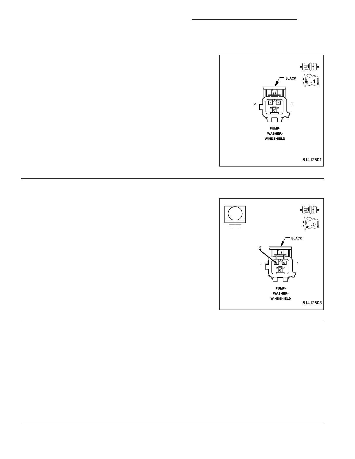
Disconnect the Washer Pump Motor harness connector.
Connect a jumper wire between cavity 1 and cavity 2.
Turn the ignition on.
With the DRBIIIT, read DTCs.
Does the DRBIIIT display: Washer Pump Output Circuit Low?
Yes >>
No >>
WASHER PUMP MOTOR GROUND CIRCUIT OPEN
3.
Turn the ignition off.
Disconnect the Washer Pump Motor harness connector.
Measure the resistance between ground and the Washer Pump Motor
Ground circuit.
Is the resistance above 5.0 ohms?
Yes >>
No >>
Replace the Washer Pump Motor - Front in accordance with the Service Information.
Perform BODY VERIFICATION TEST - VER 1.
Go To 3
Repair the Washer Pump Motor Ground circuit for an
open.
Perform BODY VERIFICATION TEST - VER 1.
Go To 4
WASHER PUMP MOTOR CONTROL CIRCUIT OPEN
4.
Turn the ignition off.
Disconnect the Washer Pump Motor harness connector.
Disconnect the IPM C3 harness connector.
Measure the resistance of the Washer Pump Motor Control circuit.
Is the resistance above 5.0 ohms?
Yes >>
No >>
Repair the Washer Pump Motor Control circuit for an
open.
Perform BODY VERIFICATION TEST - VER 1.
Go To 5
Page 12

8R - 12 WIPERS/WASHERS - ELECTRICAL DIAGNOSTICS DR/DH
FCM-WASHER PUMP OUTPUT CIRCUIT OPEN (CONTINUED)
POWER DISTRIBUTION CENTER
5.
Turn the ignition off.
Disconnect the FCM from the IPM.
Disconnect the IPM C3 harness connector.
Measure the internal resistance of the IPM Washer Pump Motor Control circuit.
Is the resistance above 5.0 ohms?
Yes >>
No >>
Replace the Power Distribution Center (PDC) in accordance with the Service Information.
Perform BODY VERIFICATION TEST - VER 1.
Replace the Front Control Module (FCM) in accordance with the Service Information.
Perform BODY VERIFICATION TEST - VER 1.
Page 13

DR/DH WIPERS/WASHERS - ELECTRICAL DIAGNOSTICS 8R - 13
FCM-WIPER ON-OFF RELAY OUTPUT CIRCUIT HIGH
Page 14
8R - 14 WIPERS/WASHERS - ELECTRICAL DIAGNOSTICS DR/DH
FCM-WIPER ON-OFF RELAY OUTPUT CIRCUIT HIGH (CONTINUED)
For the Wiper Washer system circuit diagram (Refer to 8 - ELECTRICAL/WIPERS/WASHERS - SCHEMATICS AND
DIAGRAMS).
For a complete wiring diagram Refer to Section 8W.
• When Monitored:
• Set Condition:
Possible Causes
WIPER ON/OFF RELAY
FRONT CONTROL MODULE
POWER DISTRIBUTION CENTER
INTERMITTENT CONDITION
1.
Turn the ignition on.
With the DRBIIIT, clear all FCM DTC’s.
Turn the Wipers ON than OFF.
With the DRBIIIT, read the DTC information.
Does the DRBIIIT read: Wiper ON-OFF Relay
Output Circuit High?
Yes >>
No >>
Go To 2
The condition that caused the symptom
is currently not present. Inspect the
related wiring for a possible intermittent
condition. Look for any chafed, pierced,
pinched, or partially broken wires.
Perform BODY VERIFICATION TEST VER 1.
Page 15
DR/DH WIPERS/WASHERS - ELECTRICAL DIAGNOSTICS 8R - 15
FCM-WIPER ON-OFF RELAY OUTPUT CIRCUIT HIGH (CONTINUED)
WIPER ON/OFF RELAY
2.
Turn the ignition off.
Remove the Wiper On/Off Relay from the IPM.
Turn the ignition on.
Activate the Wiper Switch to all speed positions.
With the DRBIIIT, read DTCs.
Does the DRBIIIT display: Wiper On/Off Relay Output Circuit
High?
Yes >>
No >>
POWER DISTRIBUTION CENTER
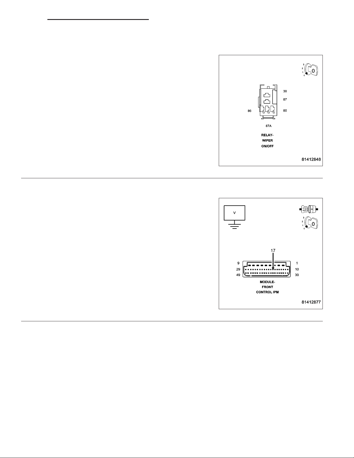
3.
Turn the ignition off.
Remove the Wiper On/Off Relay from the IPM.
Remove the FCM from the IPM.
Measure the voltage between the Wiper On/Off Relay Control circuit
and ground in the IPM.
Is there any voltage present?
Yes >>
No >>
Replace the Wiper On/Off Relay in accordance with the
Service Information.
Perform BODY VERIFICATION TEST - VER 1.
Go To 3
Replace the Power Distribution Center (PDC) in accordance with the Service Information.
Perform BODY VERIFICATION TEST - VER 1.
Replace the Front Control Module (FCM) in accordance
with the Service Information.
Perform BODY VERIFICATION TEST - VER 1.
Page 16
8R - 16 WIPERS/WASHERS - ELECTRICAL DIAGNOSTICS DR/DH
FCM-WIPER ON-OFF RELAY OUTPUT CIRCUIT OPEN
Page 17
DR/DH WIPERS/WASHERS - ELECTRICAL DIAGNOSTICS 8R - 17
FCM-WIPER ON-OFF RELAY OUTPUT CIRCUIT OPEN (CONTINUED)
For the Wiper Washer system circuit diagram (Refer to 8 - ELECTRICAL/WIPERS/WASHERS - SCHEMATICS AND
DIAGRAMS).
For a complete wiring diagram Refer to Section 8W.
• When Monitored:
With the ignition on
• Set Condition:
The FCM detects an open condition on the BUS
Possible Causes
WIPER ON/OFF RELAY
FRONT CONTROL MODULE
POWER DISTRIBUTION CENTER
INTERMITTENT CONDITION
1.
Turn the ignition on.
With the DRBIIIT, clear all FCM DTC’s.
Turn the Wipers ON then OFF.
With the DRBIIIT, read the DTC information.
Does the DRBIIIT read: Wiper ON-OFF Relay
Output Circuit Open?
Yes >>
No >>
Go To 2
The condition that caused the symptom
is currently not present. Inspect the
related wiring for a possible intermittent
condition. Look for any chafed, pierced,
pinched, or partially broken wires.
Perform BODY VERIFICATION TEST VER 1.
Page 18
8R - 18 WIPERS/WASHERS - ELECTRICAL DIAGNOSTICS DR/DH
FCM-WIPER ON-OFF RELAY OUTPUT CIRCUIT OPEN (CONTINUED)
WIPER ON/OFF RELAY
2.
Turn the ignition off.
Install a substitute relay in place of the Wiper On/Off Relay.
Turn the ignition on.
With the DRBIIIT, read DTCs.
Does the DRBIIIT display: Wiper On/Off Relay Output Circuit
Open?
Yes >>
No >>
POWER DISTRIBUTION CENTER
3.
Turn the ignition off.
Remove the Wiper On/Off Relay from the IPM.
Remove the FCM from the IPM.
Measure the resistance of the Wiper On/Off Control circuit in the IPM.
Is the resistance above 5.0 ohms?
Yes >>
No >>
Go To 3
Replace the Wiper On/Off Relay in accordance with the
Service Information.
Perform BODY VERIFICATION TEST - VER 1.
Replace the Power Distribution Center (PDC ) in accordance with the Service Information.
Perform BODY VERIFICATION TEST - VER 1.
Replace the Front Control Module (FCM) in accordance with the Service Information.
Perform BODY VERIFICATION TEST - VER 1.
Page 19
DR/DH WIPERS/WASHERS - ELECTRICAL DIAGNOSTICS 8R - 19
FCM-WIPER ON-OFF RELAY OUTPUT CIRCUIT LOW
Page 20
8R - 20 WIPERS/WASHERS - ELECTRICAL DIAGNOSTICS DR/DH
FCM-WIPER ON-OFF RELAY OUTPUT CIRCUIT LOW (CONTINUED)
For the Wiper Washer system circuit diagram (Refer to 8 - ELECTRICAL/WIPERS/WASHERS - SCHEMATICS AND
DIAGRAMS).
For a complete wiring diagram Refer to Section 8W.
• When Monitored:
With the ignition on
• Set Condition:
When the FCM detects a low condition in the relay
Possible Causes
WIPER ON/OFF RELAY
FRONT CONTROL MODULE
POWER DISTRIBUTION CENTER
INTERMITTENT CONDITION
1.
Turn the ignition on.
With the DRBIIIT, clear all FCM DTC’s.
Turn the Wipers ON then OFF.
With the DRBIIIT, read the DTC information.
Does the DRBIIIT read: Wiper On-Off Relay
Output Circuit Low?
Yes >>
No >>
Go To 2
The condition that caused the symptom
is currently not present. Inspect the
related wiring for a possible intermittent
condition. Look for any chafed, pierced,
pinched, or partially broken wires.
Perform BODY VERIFICATION TEST VER 1.
Page 21
DR/DH WIPERS/WASHERS - ELECTRICAL DIAGNOSTICS 8R - 21
FCM-WIPER ON-OFF RELAY OUTPUT CIRCUIT LOW (CONTINUED)
WIPER ON/OFF RELAY
2.
Turn the ignition off.
Install a substitute relay in place of the Wiper On/Off Relay.
Turn the ignition on.
With the DRBIIIT, read DTCs.
Does the DRBIIIT display: Wiper On/Off Relay Output Circuit
Low?
Yes >>
No >>
POWER DISTRIBUTION CENTER
3.
Turn the ignition off.
Remove the Wiper On/Off Relay.
Remove the FCM from the IPM.
Measure the resistance between ground and the Wiper On/Off Relay Control circuit in the IPM.
Is the resistance below 5.0 ohms?
Yes >>
No >>
Go To 3
Replace the Wiper On/Off Relay in accordance with the
Service Information.
Perform BODY VERIFICATION TEST - VER 1.
Replace the Power Distribution Center (PDC) in accordance with the Service Information.
Perform BODY VERIFICATION TEST - VER 1.
Replace the Front Control Module (FCM) in accordance with the Service Information.
Perform BODY VERIFICATION TEST - VER 1.
Page 22
8R - 22 WIPERS/WASHERS - ELECTRICAL DIAGNOSTICS DR/DH
FCM-WIPER PARK SWITCH INPUT PERFORMANCE
Page 23
DR/DH WIPERS/WASHERS - ELECTRICAL DIAGNOSTICS 8R - 23
FCM-WIPER PARK SWITCH INPUT PERFORMANCE (CONTINUED)
For the Wiper Washer system circuit diagram (Refer to 8 - ELECTRICAL/WIPERS/WASHERS - SCHEMATICS AND
DIAGRAMS).
For a complete wiring diagram Refer to Section 8W.
• When Monitored:
With the ignition on
• Set Condition:
The FCM detects a performance condition on the BUS
Possible Causes
WIPER MOTOR PARK SWITCH GROUND CIRCUIT OPEN
WIPER MOTOR
WIPER PARK SWITCH SENSE CIRCUIT SHORT TO VOLTAGE
WIPER PARK SWITCH SENSE CIRCUIT SHORT TO GROUND
WIPER PARK SWITCH SENSE CIRCUIT OPEN
POWER DISTRIBUTION CENTER
FRONT CONTROL MODULE
INTERMITTENT CONDITION
1.
Turn the ignition on.
With the DRBIIIT, clear all FCM DTC’s.
Turn the Wipers ON then OFF.
With the DRBIIIT, read the DTC information.
Does the DRBIIIT read: Wiper Park Switch
Input Performance?
Yes >>
No >>
Go To 2
The condition that caused the symptom
is currently not present. Inspect the
related wiring for a possible intermittent
condition. Look for any chafed, pierced,
pinched, or partially broken wires.
Perform BODY VERIFICATION TEST VER 1.
Page 24

8R - 24 WIPERS/WASHERS - ELECTRICAL DIAGNOSTICS DR/DH
FCM-WIPER PARK SWITCH INPUT PERFORMANCE (CONTINUED)
WIPER MOTOR PARK SWITCH GROUND CIRCUIT OPEN
2.
Turn the ignition off.
Disconnect the Wiper Motor harness connector.
Measure the resistance between ground and the Wiper Motor Park
Switch Ground circuit.
Is the resistance above 5.0 ohms?
Yes >>
No >>
WIPER MOTOR
3.
Turn the ignition off.
Disconnect the Wiper Motor harness connector.
Measure the internal resistance of the Wiper Motor between terminal pin 2 and pin 3.
Is the resistance above 5.0 ohms?
Yes >>
No >>
Repair the Wiper Motor Park Switch Ground circuit for an
open.
Perform BODY VERIFICATION TEST - VER 1.
Go To 3
Replace the Wiper Motor - Front in accordance with the Service Information.
Perform BODY VERIFICATION TEST - VER 1.
Go To 4
WIPER PARK SWITCH SENSE CIRCUIT SHORT TO VOLTAGE
4.
Turn the ignition off.
Disconnect the IPM C4 harness connector.
Disconnect the Wiper Motor harness connector.
Measure the voltage between the Wiper Park Switch Sense circuit and
ground.
Is there any voltage present?
Yes >>
No >>
Repair the Wiper Park Switch Sense circuit for a short to
voltage.
Perform BODY VERIFICATION TEST - VER 1.
Go To 5
Page 25

DR/DH WIPERS/WASHERS - ELECTRICAL DIAGNOSTICS 8R - 25
FCM-WIPER PARK SWITCH INPUT PERFORMANCE (CONTINUED)
WIPER PARK SWITCH SENSE CIRCUIT SHORT TO GROUND
5.
Turn the ignition off.
Disconnect the IPM C4 harness connector.
Disconnect the Wiper Motor harness connector.
Measure the resistance between ground and the Wiper Park Switch
Sense circuit.
Is the resistance below 5.0 ohms?
Yes >>
No >>
WIPER PARK SWITCH SENSE CIRCUIT OPEN
6.
Turn the ignition off.
Disconnect the IPM C4 harness connector.
Disconnect the Wiper Motor harness connector.
Measure the resistance of the Wiper Park Switch Sense circuit.
Is the resistance above 5.0 ohms?
Yes >>
No >>
Repair the Wiper Park Switch Sense circuit for a short to
ground.
Perform BODY VERIFICATION TEST - VER 1.
Go To 6
Repair the Wiper Park Switch Sense circuit for an open.
Perform BODY VERIFICATION TEST - VER 1.
Go To 7
POWER DISTRIBUTION CENTER
7.
Turn the ignition off.
Remove the FCM from the IPM.
Disconnect the IPM C4 harness connector.
Measure the internal resistance of the Wiper Park Switch Sense circuit.
Is the resistance above 5.0 ohms?
Yes >>
No >>
Replace the Power Distribution Center (PDC) in accordance with the Service Information.
Perform BODY VERIFICATION TEST - VER 1.
Replace the Front Control Module (FCM) in accordance with the Service Information.
Perform BODY VERIFICATION TEST - VER 1.
Page 26

8R - 26 WIPERS/WASHERS - ELECTRICAL DIAGNOSTICS DR/DH
FCM-WIPER SPEED RELAY OUTPUT CIRCUIT HIGH
Page 27

DR/DH WIPERS/WASHERS - ELECTRICAL DIAGNOSTICS 8R - 27
FCM-WIPER SPEED RELAY OUTPUT CIRCUIT HIGH (CONTINUED)
For the Wiper Washer system circuit diagram (Refer to 8 - ELECTRICAL/WIPERS/WASHERS - SCHEMATICS AND
DIAGRAMS).
For a complete wiring diagram Refer to Section 8W.
• When Monitored:
With the ignition on
• Set Condition:
The FCM detects a HIGH condition the BUS
Possible Causes
WIPER HIGH/LOW RELAY
FRONT CONTROL MODULE
POWER DISTRIBUTION CENTER
INTERMITTENT CONDITION
1.
Turn the ignition on.
With the DRBIIIT, clear all FCM DTC’s.
Actuate the Wipers in all speed positions.
With the DRBIIIT, read the DTC information.
Does the DRBIIIT read: Wiper Speed Relay
Output Circuit High?
Yes >>
No >>
Go To 2
The condition that caused the symptom
is currently not present. Inspect the
related wiring for a possible intermittent
condition. Look for any chafed, pierced,
pinched, or partially broken wires.
Perform BODY VERIFICATION TEST VER 1.
Page 28

8R - 28 WIPERS/WASHERS - ELECTRICAL DIAGNOSTICS DR/DH
FCM-WIPER SPEED RELAY OUTPUT CIRCUIT HIGH (CONTINUED)
WIPER HIGH/LOW RELAY
2.
Turn the ignition off.
Remove the Wiper High/Low Relay from the IPM.
Turn the ignition on.
Activate the Wiper Switch to all speed positions.
With the DRBIIIT, read DTCs.
Does the DRBIIIT display: Wiper Speed Relay Output Circuit
Open?
Yes >>
No >>
POWER DISTRIBUTION CENTER
3.
Turn the ignition off.
Remove the Wiper High/Low Relay from the IPM.
Remove the FCM from the IPM.
Measure the voltage between the Wiper High/Low Relay Control circuit
and ground in the IPM.
Is there any voltage present?
Yes >>
No >>
Replace the Wiper High/Low Relay in accordance with the
Service Information.
Perform BODY VERIFICATION TEST - VER 1.
Go To 3
Replace the Power Distribution Center (PDC) in accordance with the Service Information.
Perform BODY VERIFICATION TEST - VER 1.
Replace the Front Control Module (FCM) in accordance
with the Service Information.
Perform BODY VERIFICATION TEST - VER 1.
Page 29

DR/DH WIPERS/WASHERS - ELECTRICAL DIAGNOSTICS 8R - 29
FCM-WIPER SPEED RELAY OUTPUT CIRCUIT LOW
Page 30

8R - 30 WIPERS/WASHERS - ELECTRICAL DIAGNOSTICS DR/DH
FCM-WIPER SPEED RELAY OUTPUT CIRCUIT LOW (CONTINUED)
For the Wiper Washer system circuit diagram (Refer to 8 - ELECTRICAL/WIPERS/WASHERS - SCHEMATICS AND
DIAGRAMS).
For a complete wiring diagram Refer to Section 8W.
• When Monitored:
With the ignition on
• Set Condition:
The FCM detects a low condition
Possible Causes
WIPER ON/OFF RELAY
FRONT CONTROL MODULE
POWER DISTRIBUTION CENTER
INTERMITTENT CONDITION
1.
Turn the ignition on.
With the DRBIIIT, clear all FCM DTC’s.
Actuate the Wipers in all speed positions.
With the DRBIIIT, read the DTC information.
Does the DRBIIIT read: Wiper Speed Relay
Output Circuit Low?
Yes >>
No >>
Go To 2
The condition that caused the symptom
is currently not present. Inspect the
related wiring for a possible intermittent
condition. Look for any chafed, pierced,
pinched, or partially broken wires.
Perform BODY VERIFICATION TEST VER 1.
Page 31

DR/DH WIPERS/WASHERS - ELECTRICAL DIAGNOSTICS 8R - 31
FCM-WIPER SPEED RELAY OUTPUT CIRCUIT LOW (CONTINUED)
WIPER HIGH/LOW RELAY
2.
Turn the ignition off.
Install a substitute relay in place of the Wiper High/Low Relay.
Turn the ignition on.
Activate the Wiper Switch to all speed positions.
With the DRBIIIT, read DTCs.
Does the DRBIIIT display: Wiper Speed Relay Output Circuit
Low?
Yes >>
No >>
POWER DISTRIBUTION CENTER
3.
Turn the ignition off.
Remove the Wiper High/Low Relay.
Remove the FCM from the IPM.
Measure the resistance between ground and the Wiper High/Low Relay Control circuit in the IPM.
Is the resistance below 5.0 ohms?
Yes >>
No >>
Go To 3
Replace the Wiper High/Low Relay in accordance with the
Service Information.
Perform BODY VERIFICATION TEST - VER 1.
Replace the Power Distribution Center (PDC) in accordance with the Service Information.
Perform BODY VERIFICATION TEST - VER 1.
Replace the Front Control Module (FCM) in accordance with the Service Information.
Perform BODY VERIFICATION TEST - VER 1.
Page 32

8R - 32 WIPERS/WASHERS - ELECTRICAL DIAGNOSTICS DR/DH
FCM-WIPER SPEED RELAY OUTPUT CIRCUIT OPEN
Page 33

DR/DH WIPERS/WASHERS - ELECTRICAL DIAGNOSTICS 8R - 33
FCM-WIPER SPEED RELAY OUTPUT CIRCUIT OPEN (CONTINUED)
For the Wiper Washer system circuit diagram (Refer to 8 - ELECTRICAL/WIPERS/WASHERS - SCHEMATICS AND
DIAGRAMS).
For a complete wiring diagram Refer to Section 8W.
• When Monitored:
With the ignition on
• Set Condition:
The FCM detects an open condition
Possible Causes
WIPER HIGH/LOW RELAY
FRONT CONTROL MODULE
POWER DISTRIBUTION CENTER
INTERMITTENT CONDITION
1.
Turn the ignition on.
With the DRBIII T, clear all FCM DTC’s.
Actuate the Wipers in all speed positions.
With the DRBIIIT, read the DTC information.
Does the DRBIIIT read: Wiper Speed Relay
Output Circuit Open?
Yes >>
No >>
Go To 2
The condition that caused the symptom
is currently not present. Inspect the
related wiring for a possible intermittent
condition. Look for any chafed, pierced,
pinched, or partially broken wires.
Perform BODY VERIFICATION TEST VER 1.
Page 34

8R - 34 WIPERS/WASHERS - ELECTRICAL DIAGNOSTICS DR/DH
FCM-WIPER SPEED RELAY OUTPUT CIRCUIT OPEN (CONTINUED)
WIPER HIGH/LOW RELAY
2.
Turn the ignition off.
Install a substitute relay in place of the Wiper High/Low Relay.
Turn the ignition on.
Activate the Wiper Switch to all speed positions.
With the DRBIIIT, read DTCs.
Does the DRBIIIT display: Wiper Speed Relay Output Circuit
Open?
Yes >>
No >>
POWER DISTRIBUTION CENTER
3.
Turn the ignition off.
Remove the Wiper High/Low Relay from the IPM.
Remove the FCM from the IPM.
Measure the resistance of the Wiper High/Low Control circuit in the IPM.
Is the resistance above 5.0 ohms?
Yes >>
No >>
Go To 3
Replace the Wiper High/Low Relay in accordance with the
Service Information.
Perform BODY VERIFICATION TEST - VER 1.
Replace the Power Distribution Center (PDC ) in accordance with the Service Information.
Perform BODY VERIFICATION TEST - VER 1.
Replace the Front Control Module (FCM) in accordance with the Service Information.
Perform BODY VERIFICATION TEST - VER 1.
Page 35

DR/DH WIPERS/WASHERS - ELECTRICAL DIAGNOSTICS 8R - 35
MIC-WASH-BEAM INPUT CIRCUIT SHORTED
Page 36

8R - 36 WIPERS/WASHERS - ELECTRICAL DIAGNOSTICS DR/DH
MIC-WASH-BEAM INPUT CIRCUIT SHORTED (CONTINUED)
For the Wiper Washer system circuit diagram (Refer to 8 - ELECTRICAL/WIPERS/WASHERS - SCHEMATICS AND
DIAGRAMS).
For a complete wiring diagram Refer to Section 8W.
• When Monitored:
With the ignition on.
• Set Condition:
The Instrument Cluster detects less than 0.05 volts on the Wash/Beam Select Switch Feed circuit.
Possible Causes
MULTI- FUNCTION SWITCH
INSTRUMENT CLUSTER
(G194) WASH/BEAM SELECT SWITCH FEED CIRCUIT SHORT TO GROUND
INTERMITTENT CONDITION
1.
Turn the ignition on.
With the DRBIIIT, clear all MIC DTC’s.
Turn the Wipers on.
With the DRBIIIT, read the DTC information.
Does the DRBIIIT read: Wash-Beam Input Circuit Shorted?
Yes >>
No >>
MULTI- FUNCTION SWITCH
2.
Turn the ignition off.
Disconnect the Multi- Function Switch harness connector.
Turn the ignition on.
With the DRBIIIT in Sensors, read the Wash - Beam SW Volts.
Does the DRBIIIT display more than 4.5 volts?
Go To 2
The condition that caused the symptom
is currently not present. Inspect the
related wiring for a possible intermittent
condition. Look for any chafed, pierced,
pinched, or partially broken wires.
Perform BODY VERIFICATION TEST VER 1.
Yes >>
No >>
Replace the Multi- Function Switch in accordance with the Service Information.
Perform BODY VERIFICATION TEST - VER 1.
Go To 3
Page 37

DR/DH WIPERS/WASHERS - ELECTRICAL DIAGNOSTICS 8R - 37
MIC-WASH-BEAM INPUT CIRCUIT SHORTED (CONTINUED)
WASH/BEAM SELECT SWITCH FEED CIRCUIT SHORT TO GROUND
3.
Turn the ignition off.
Disconnect the Instrument Cluster C4 harness connector.
Disconnect the Multi- Function Switch harness connector.
Measure the resistance between ground and the(G194) Wash/beam
Select Switch Feed circuit.
Is the resistance below 5.0 ohms?
Yes >>
No >>
Repair the (G194) Wash/Beam Select Switch Feed circuit
for a short to ground.
Perform BODY VERIFICATION TEST - VER 1.
Replace and configure the Instrument Cluster in accor-
dance with the Service Information.
Perform BODY VERIFICATION TEST - VER 1.
Page 38

8R - 38 WIPERS/WASHERS - ELECTRICAL DIAGNOSTICS DR/DH
MIC-WIPER SWITCH INPUT CIRCUIT OPEN
Page 39

DR/DH WIPERS/WASHERS - ELECTRICAL DIAGNOSTICS 8R - 39
MIC-WIPER SWITCH INPUT CIRCUIT OPEN (CONTINUED)
For the Wiper Washer system circuit diagram (Refer to 8 - ELECTRICAL/WIPERS/WASHERS - SCHEMATICS AND
DIAGRAMS).
For a complete wiring diagram Refer to Section 8W.
• When Monitored:
With the ignition on.
• Set Condition:
The Instrument Cluster detects above 5.0 volts on the multi-function circuit.
Possible Causes
MULTI- FUNCTION SWITCH
INSTRUMENT CLUSTER
(W52) INTERMITTENT WIPER SWITCH SENSE CIRCUIT OPEN
INTERMITTENT CONDITION
1.
Turn the ignition on.
With the DRBIIIT, clear all MIC DTC’s.
Turn the Wipers ON.
With the DRBIIIT, read the DTC information.
Does the DRBIIIT read: Wiper Switch Input Circuit Open?
Yes >>
No >>
Go To 2
The condition that caused the symptom
is currently not present. Inspect the
related wiring for a possible intermittent
condition. Look for any chafed, pierced,
pinched, or partially broken wires.
Perform BODY VERIFICATION TEST VER 1.
Page 40

8R - 40 WIPERS/WASHERS - ELECTRICAL DIAGNOSTICS DR/DH
MIC-WIPER SWITCH INPUT CIRCUIT OPEN (CONTINUED)
MULTI- FUNCTION SWITCH
2.
Turn the ignition off.
Disconnect the Multi- Function Switch harness connector.
Ensure that the Multi- Function Switch is in the Off position.
Measure the internal resistance of the Multi- Function Switch between
cavity 2 and cavity 4.
Does the Multi- Function Switch measure more than 5.0 ohms?
Yes >>
No >>
INTERMITTENT WIPER SWITCH SENSE CIRCUIT OPEN
3.
Turn the ignition off.
Disconnect the Multi- Function Switch harness connector.
Disconnect the Instrument Cluster C4 harness connector.
Measure the resistance of the (W52) Intermittent Wiper Switch Sense
circuit.
Replace the Multi- Function Switch in accordance with the
Service Information.
Perform BODY VERIFICATION TEST - VER 1.
Go To 3
Is the resistance above 5.0 ohms?
Yes >>
No >>
Repair the (W52) Intermittent Wiper Switch Sense circuit
for an open.
Perform BODY VERIFICATION TEST - VER 1.
Replace and configure the Instrument Cluster in accor-
dance with the Service Information.
Perform BODY VERIFICATION TEST - VER 1.
Page 41

DR/DH WIPERS/WASHERS - ELECTRICAL DIAGNOSTICS 8R - 41
MIC-WIPER SWITCH INPUT CIRCUIT SHORTED
Page 42

8R - 42 WIPERS/WASHERS - ELECTRICAL DIAGNOSTICS DR/DH
MIC-WIPER SWITCH INPUT CIRCUIT SHORTED (CONTINUED)
For the Wiper Washer system circuit diagram (Refer to 8 - ELECTRICAL/WIPERS/WASHERS - SCHEMATICS AND
DIAGRAMS).
For a complete wiring diagram Refer to Section 8W.
• When Monitored:
With the ignition on.
• Set Condition:
The Instrument Cluster detects the multifunction circuit voltage is below 0.05 volts.
Possible Causes
MULTI- FUNCTION SWITCH
(W52) INTERMITTENT WIPER SWITCH SENSE CIRCUIT SHORT TO GROUND
INSTRUMENT CLUSTER
INTERMITTENT CONDITION
1.
Turn the ignition on.
With the DRBIIIT, clear all MIC DTC’s.
Turn the Wipers ON.
With the DRBIIIT, read the DTC information.
Does the DRBIIIT read: Wiper Switch Input Circuit Short?
Yes >>
No >>
Go To 2
The condition that caused the symptom
is currently not present. Inspect the
related wiring for a possible intermittent
condition. Look for any chafed, pierced,
pinched, or partially broken wires.
Perform BODY VERIFICATION TEST VER 1.
Page 43

DR/DH WIPERS/WASHERS - ELECTRICAL DIAGNOSTICS 8R - 43
MIC-WIPER SWITCH INPUT CIRCUIT SHORTED (CONTINUED)
MULTI- FUNCTION SWITCH
2.
Turn the ignition off.
Disconnect the Multi- Function Switch harness connector.
Turn the ignition on.
With the DRBIIIT, read DTCs.
Does the DRBIIIT display: Wiper Switch Input Circuit Open?
Yes >>
No >>
INTERMITTENT WIPER SWITCH SENSE CIRCUIT SHORT TO GROUND
3.
Turn the ignition off.
Disconnect the Multi- Function Switch harness connector.
Disconnect the Instrument Cluster C4 harness connector.
Measure the resistance between ground and the (W52) Intermittent
Wiper Switch Sense circuit.
Is the resistance below 5.0 ohms?
Yes >>
No >>
Replace the Multi- Function Switch in accordance with the
Service Information.
Perform BODY VERIFICATION TEST - VER 1.
Go To 3
Repair the (W52) Intermittent Wiper Switch Sense circuit
for a short to ground.
Perform BODY VERIFICATION TEST - VER 1.
Replace and configure the Instrument Cluster in accor-
dance with the Service Information.
Perform BODY VERIFICATION TEST - VER 1.
Page 44

8R - 44 WIPERS/WASHERS - ELECTRICAL DIAGNOSTICS DR/DH
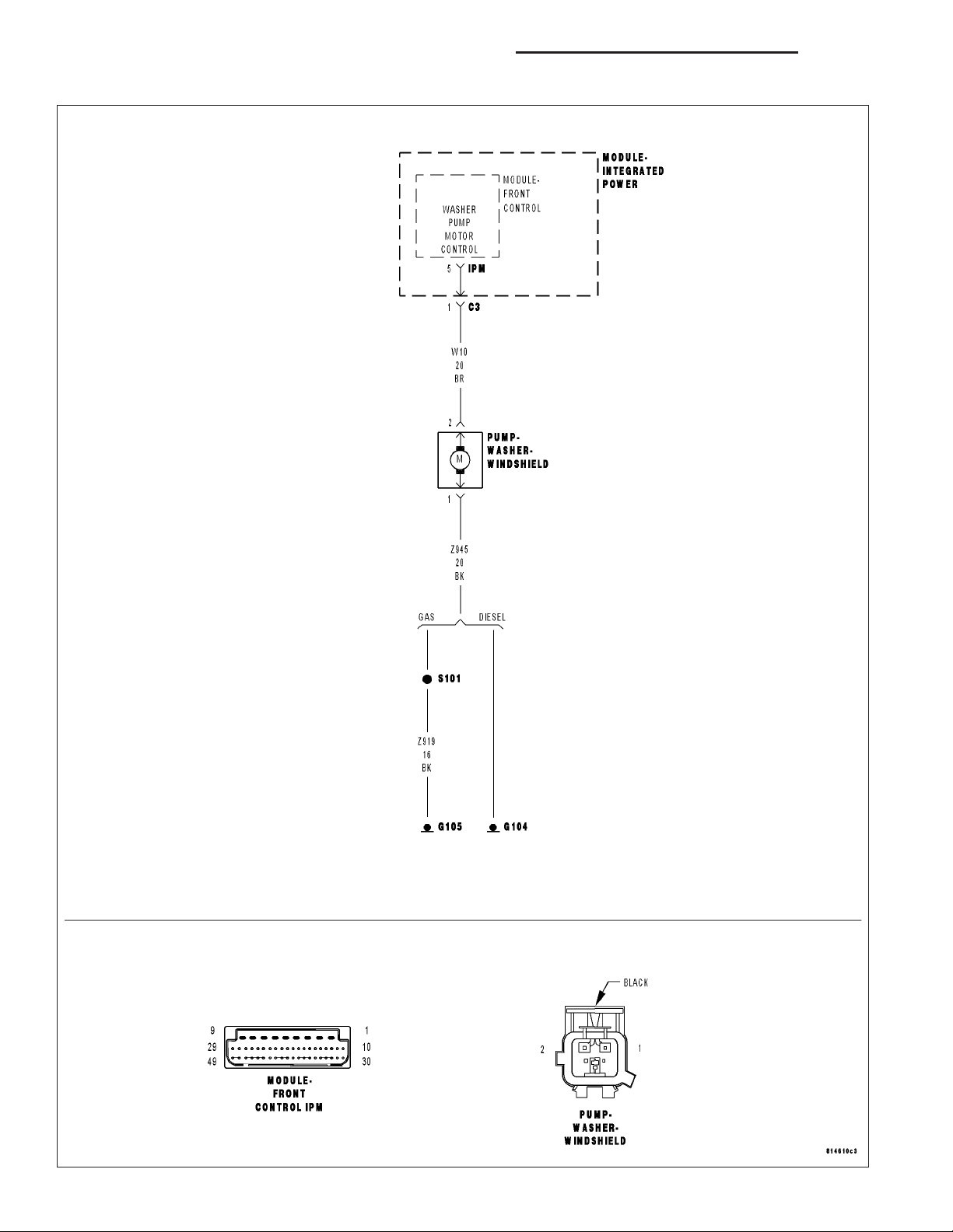
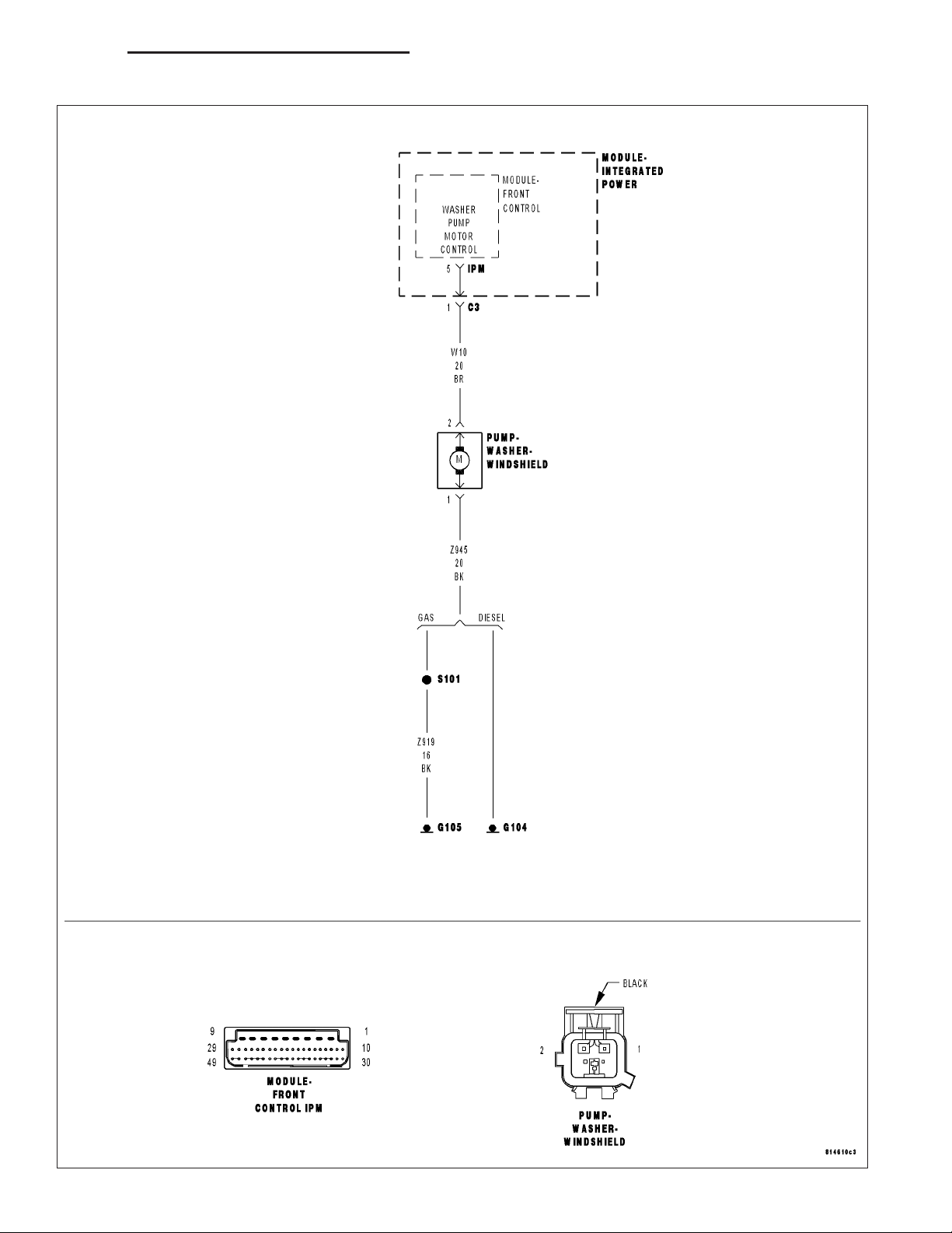
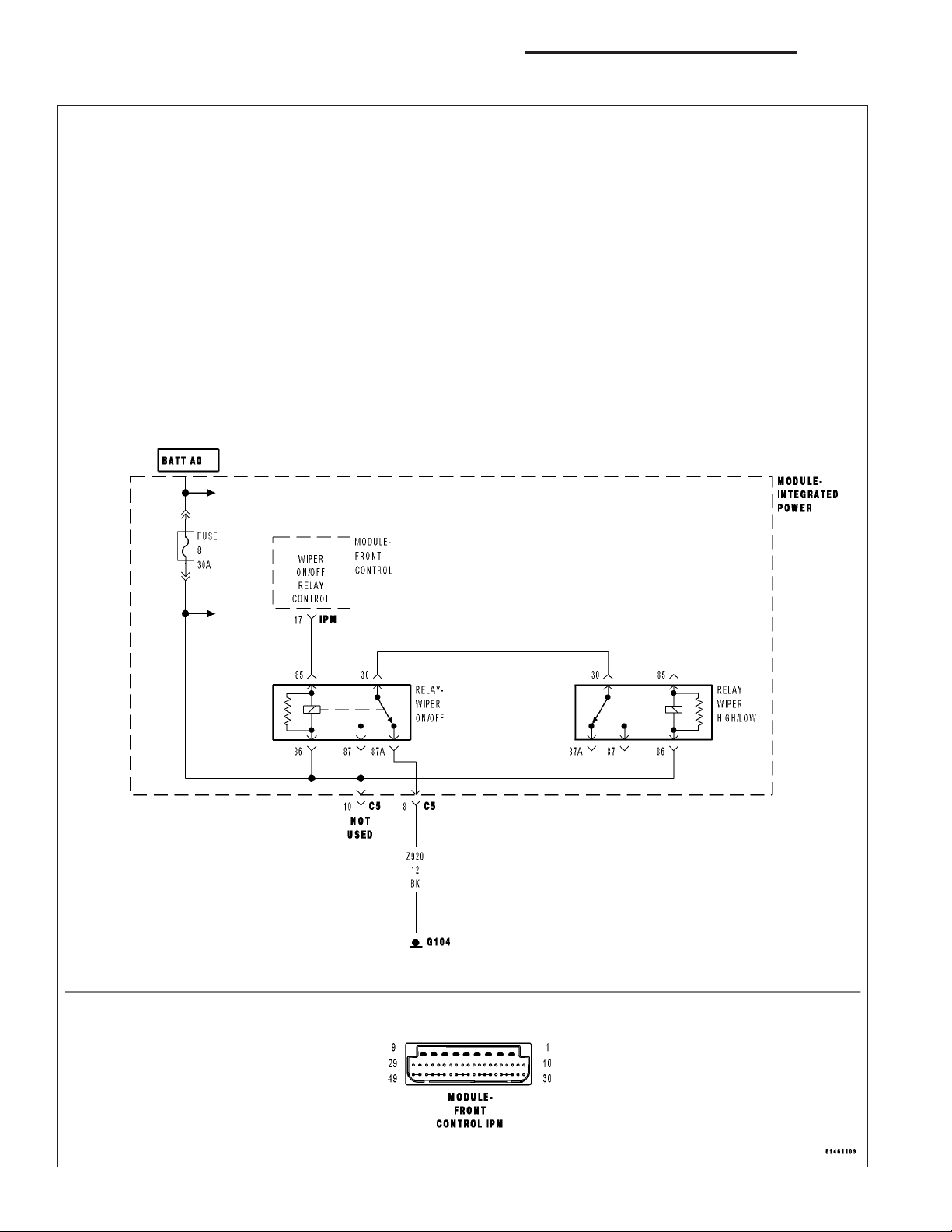
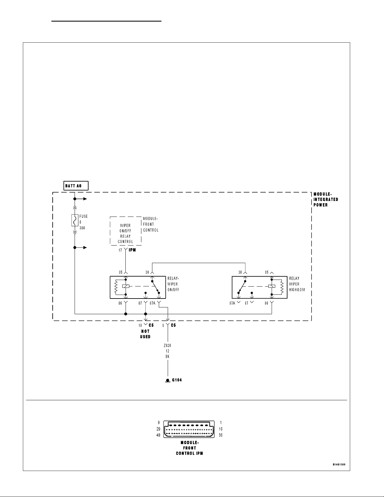
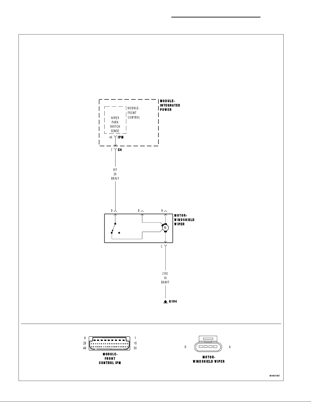
SCHEMATICS AND DIAGRAMS
WIPER WASHER SCHEMATIC
Page 45

DR/DH WIPERS/WASHERS - SERVICE INFORMATION 8R - 45
WIPERS/WASHERS - SERVICE INFORMATION
TABLE OF CONTENTS
page page
WIPERS/WASHERS - SERVICE INFORMATION
DESCRIPTION .........................46
OPERATION ...........................48
DIAGNOSIS AND TESTING
WIPER & WASHER SYSTEM .............50
CLEANING - WIPER & WASHER SYSTEM ....50
INSPECTION - WIPER & WASHER SYSTEM . . 51
CHECK VALVE
DESCRIPTION .........................52
OPERATION ...........................52
REMOVAL .............................53
INSTALLATION .........................53
SENSOR-WASHER FLUID LEVEL
DESCRIPTION .........................54
OPERATION ...........................54
REMOVAL
EXCEPT SRT-10 OR DIESEL ENGINE ......55
SRT-10 OR DIESEL ENGINE ONLY ........55
INSTALLATION
EXCEPT SRT-10 OR DIESEL ENGINE ......56
SRT-10 OR DIESEL ENGINE ONLY ........57
WASHER HOSES/TUBES
DESCRIPTION .........................57
OPERATION ...........................58
WASHER NOZZLE
DESCRIPTION .........................58
OPERATION ...........................58
REMOVAL .............................59
INSTALLATION .........................59
PUMP-WASHER-WINDSHIELD
DESCRIPTION .........................60
OPERATION ...........................60
REMOVAL
EXCEPT SRT-10 OR DIESEL ENGINE ......61
SRT-10 OR DIESEL ENGINE ONLY ........61
INSTALLATION
EXCEPT SRT-10 OR DIESEL ENGINE ......62
SRT-10 OR DIESEL ENGINE ONLY ........63
WASHER RESERVOIR
DESCRIPTION .........................63
OPERATION ...........................64
REMOVAL
EXCEPT SRT-10 OR DIESEL ENGINE ......64
SRT-10 OR DIESEL ENGINE ONLY ........65
INSTALLATION
EXCEPT SRT-10 OR DIESEL ENGINE ......66
SRT-10 OR DIESEL ENGINE ONLY ........66
WIPER ARM
DESCRIPTION .........................67
OPERATION ...........................68
REMOVAL .............................68
INSTALLATION .........................68
WIPER BLADE
DESCRIPTION .........................69
OPERATION ...........................69
REMOVAL .............................69
INSTALLATION .........................70
WIPER HIGH/LOW RELAY
DESCRIPTION .........................71
OPERATION ...........................71
WIPER MODULE
DESCRIPTION .........................72
OPERATION ...........................72
REMOVAL .............................73
INSTALLATION .........................74
WIPER ON/OFF RELAY
DESCRIPTION .........................75
OPERATION ...........................75
Page 46

8R - 46 WIPERS/WASHERS - SERVICE INFORMATION DR/DH
WIPERS/WASHERS - SERVICE INFORMATION
DESCRIPTION
An electrically operated intermittent wiper and washer system is standard factory-installed safety equipment on this
model. The wiper and washer system includes the following major components, which are described in further detail
elsewhere in this service information:
• Check Valve - The washer system check valve is integral to the wye fitting located in the washer plumbing
between the cowl plenum washer hose and the washer nozzles, and is concealed beneath the cowl plenum
cover/grille panel at the base of the windshield.
• Front Control Module - The Front Control Module (FCM) is integral to the Integrated Power Module (IPM)/
Power Distribution Center (PDC). The FCM/IPM/PDC is located in the engine compartment, near the battery.
(Refer to 8 - ELECTRICAL/POWER DISTRIBUTION/INTEGRATED POWER MODULE - DESCRIPTION).
• Instrument Cluster - The ElectroMechanical Instrument Cluster (EMIC) is also referred to as the Cab Control
Node (CCN) in this vehicle. The EMIC/CCN is located in the instrument panel above the steering column
opening, directly in front of the driver. (Refer to 8 - ELECTRICAL/INSTRUMENT CLUSTER - DESCRIPTION).
• Multi-Function Switch (6) - The multi-function switch is located on the top of the steering column, just below
the steering wheel. A control stalk that extends from the left side of the switch has a control knob on the end
that is dedicated to providing all of the driver controls for the wiper and washer systems. (Refer to 8 - ELECTRICAL/LAMPS/LIGHTING - EXTERIOR/MULTI-FUNCTION SWITCH - DESCRIPTION).
• Washer Fluid Level Switch - The washer fluid level switch is located in a dedicated hole on the lower, rear-
ward facing surface of the washer reservoir in the engine compartment.
Page 47

DR/DH WIPERS/WASHERS - SERVICE INFORMATION 8R - 47
• Washer Nozzle (4) - Two fluidic washer nozzles are secured with integral latch features to dedicated openings
in the cowl plenum cover/grille panel located near the base of the windshield.
• Washer Plumbing - The plumbing for the washer system consists of rubber hoses and molded plastic fittings.
The plumbing is routed along the right side of the engine compartment from the washer reservoir, and through
a trough near the right end of the cowl plenum cover/grille panel into the cowl plenum to the washer nozzle
fittings.
• Washer Pump/Motor - The electric washer pump/motor unit is located in a dedicated hole on the lower, rear-
ward facing surface of the washer reservoir in the engine compartment.
• Washer Reservoir (1 or 2) - On all models except the SRT-10 and those with an optional diesel engine, the
washer reservoir is combined with the engine coolant reserve bottle secured by integral mounting tabs and
screws to the right side of the cooling module shroud in the engine compartment. This combined reservoir has
separate, clearly identified washer fluid and engine coolant filler caps that are accessed from the right front
corner of the engine compartment. On SRT-10 models and those with an optional diesel engine, the washer
reservoir is separate from the engine coolant reserve bottle and is secured by screws to the back of the
upright left vertical member of the radiator support in the engine compartment. This washer reservoir filler cap
is accessed from the left front corner of the engine compartment.
• Wiper Arm & Blade (5) - The two wiper arms are secured with integral latches to the serrated ends of the two
wiper pivot shafts, which extend through the cowl plenum cover/grille panel located near the base of the windshield. The two wiper blades are secured to the two wiper arms with an integral latch, and are parked on the
glass near the bottom of the windshield when the wiper system is not in operation.
• Wiper High/Low Relay - The wiper high/low relay is an International Standards Organization (ISO) micro relay
located in the Integrated Power Module (IPM)/Power Distribution Center (PDC) in the engine compartment
near the battery.
• Wiper Module (3) - The wiper pivot shafts are the only visible components of the wiper module. The remain-
der of the module is concealed within the cowl plenum area beneath the cowl plenum cover/grille panel. The
wiper module includes the wiper module bracket, three rubber-isolated wiper module mounts, the wiper motor,
the wiper motor crank arm, the two wiper drive links, and the two wiper pivots.
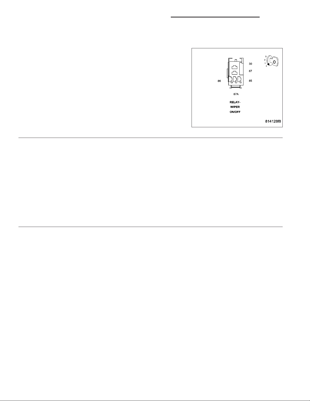
• Wiper On/Off Relay - The wiper on/off relay is an International Standards Organization (ISO) micro relay
located in the Integrated Power Module (IPM)/Power Distribution Center (PDC) in the engine compartment
near the battery.
Hard wired circuitry connects the wiper and washer system components to the electrical system of the vehicle.
These hard wired circuits are integral to several wire harnesses, which are routed throughout the vehicle and
retained by many different methods. These circuits may be connected to each other, to the vehicle electrical system
and to the wiper and washer system components through the use of a combination of soldered splices, splice block
connectors, and many different types of wire harness terminal connectors and insulators. Refer to the appropriate
wiring information. The wiring information includes wiring diagrams, proper wire and connector repair procedures,
further details on wire harness routing and retention, as well as pin-out and location views for the various wire harness connectors, splices and grounds.
Page 48

8R - 48 WIPERS/WASHERS - SERVICE INFORMATION DR/DH
OPERATION
The wiper and washer system is designed to provide
the vehicle operator with a convenient, safe, and reliable means of maintaining visibility through the windshield glass. The various components of this system
are designed to convert electrical energy produced by
the vehicle electrical system into the mechanical
action of the wiper blades to wipe the outside surface
of the glass, as well as into the hydraulic action of the
washer system to apply washer fluid stored in an onboard reservoir to the area of the glass to be wiped.
When combined, these components provide the
means to effectively maintain clear visibility for the
vehicle operator by removing excess accumulations of
rain, snow, bugs, mud, or other minor debris from the
outside windshield glass surface that might be
encountered while driving the vehicle under numerous
types of inclement operating conditions.
The vehicle operator initiates all wiper and washer system functions with the control knob (1) on the end of the
control stalk (2) of the multi-function switch that extends from the left side of the steering column, just below the
steering wheel. Rotating the control knob on the end of the control stalk, selects the Off, Delay, Low, or High wiper
system operating modes. In the Delay mode, the control knob also allows the vehicle operator to select from one of
five intermittent wipe Delay intervals. Depressing the control knob towards the steering column actuates the momentary washer system switch, which selects the Wash, Wipe-After-Wash, and Pulse Wipe Modes depending upon
when and how long the switch is held closed. The multi-function switch provides hard wired resistor multiplexed
inputs to the ElectroMechanical Instrument Cluster (EMIC) for all of the wiper and washer system functions. The
EMIC then sends electronic messages to the Front Control Module (FCM) over the Programmable Communications
Interface (PCI) data bus requesting the appropriate wiper and washer system operating modes.
Wiper and washer system operation are completely controlled by the instrument cluster and FCM logic circuits, and
that logic will only allow these systems to operate when the ignition switch is in the Accessory or On positions.
Battery current is directed from a B(+) fuse in the Integrated Power Module (IPM)/Power Distribution Center (PDC)
to the wiper on/off relay and the wiper high/low relay in the IPM/PDC through a fused B(+) circuit. The FCM uses
low side drivers to control wiper system operation by energizing or de-energizing the wiper high/low and wiper on/off
relays. The FCM uses a high side driver to control the operation of the washer pump motor unit. The multi-function
switch circuitry receives a clean ground output from the instrument cluster on a multi-function switch return circuit,
then provides resistor multiplexed inputs to the instrument cluster on an intermittent wipe mux circuit to indicate the
selected wiper system mode and on a wash/beam select mux circuit to indicate the selected washer system mode.
The hard wired circuits and components of the wiper and washer system may be diagnosed and tested using conventional diagnostic tools and methods. However, conventional diagnostic methods may not prove conclusive in the
diagnosis of the EMIC, the FCM, or the electronic message inputs to or outputs from the EMIC or the FCM that
control the wiper and washer system operating modes. The most reliable, efficient, and accurate means to diagnose
the EMIC or the FCM inputs and outputs related to the various wiper and washer system operating modes requires
the use of a diagnostic scan tool. Refer to the appropriate diagnostic information.
OPERATING MODES
Following are paragraphs that briefly describe the operation of each of the wiper and washer system operating
modes.
CONTINUOUS WIPE MODE
When the Low position of the control knob on the control stalk of the multi-function switch is selected the EMIC
sends an electronic wiper switch low message to the FCM, then the FCM energizes the wiper on/off relay. This
directs battery current through the normally open contacts of the energized wiper on/off relay and the normally
Page 49

DR/DH WIPERS/WASHERS - SERVICE INFORMATION 8R - 49
closed contacts of the de-energized wiper high/low relay to the low speed brush of the wiper motor, causing the
wipers to cycle at low speed.
When the High position of the control knob is selected the EMIC sends an electronic wiper switch high message to
the FCM, then the FCM energizes both the wiper on/off relay and the wiper high/low relay. This directs battery
current through the normally open contacts of the energized wiper on/off relay and the normally open contacts of the
energized wiper high/low relay to the high speed brush of the wiper motor, causing the wipers to cycle at high
speed.
When the Off position of the multi-function switch control knob is selected, the EMIC sends an electronic wiper
switch off message to the FCM. If the wiper motor was operating at high speed, the FCM immediately de-energizes
the wiper high/low relay causing the wiper motor to return to low speed operation. Then one of two events will
occur. The event that occurs depends upon the position of the wiper blades on the windshield at the moment that
the control knob Off position is selected.
If the wiper blades are in the down position on the windshield when the Off position is selected, the park switch that
is integral to the wiper motor is closed to ground and provides a hard wired park switch sense input to the FCM.
The FCM then de-energizes the wiper on/off relay and the wiper motor ceases to operate. If the wiper blades are
not in the down position on the windshield at the moment the Off position is selected, the park switch is an open
circuit and the FCM keeps the wiper on/off relay energized, which causes the wiper motor to continue running at low
speed until the wiper blades are in the down position on the windshield and the park switch input to the FCM is
again closed to ground.
INTERMITTENT WIPE MODE
When the control knob on the control stalk of the multi-function switch is moved to one of the Delay interval positions the EMIC sends an electronic wiper switch delay message to the FCM, then the FCM electronic intermittent
wipe logic circuit responds by calculating the correct length of time between wiper sweeps based upon the selected
delay interval input. The FCM monitors the changing state of the wiper motor park switch through a hard wired park
switch sense input. This input allows the FCM to determine the proper intervals at which to energize and de-energize the wiper on/off relay to operate the wiper motor intermittently for one low speed cycle at a time.
The FCM logic is also programmed to provide vehicle speed sensitivity to the selected intermittent wipe delay intervals. In order to provide this feature the FCM monitors electronic vehicle speed messages from the Powertrain Control Module (PCM) and doubles the selected delay interval whenever the vehicle speed is about sixteen kilometersper-hour (ten miles-per-hour) or less.
PULSE WIPE MODE
When the control knob on the control stalk of the multi-function switch is depressed to the momentary Wash position
for less than about one-half second, the EMIC sends an electronic washer switch message to the FCM, then the
FCM the energizes the wiper on/off relay for one complete wipe cycle. The FCM de-energizes the relay when the
state of the park switch sense changes to ground, parking the wiper blades near the base of the windshield.
WASH MODE
When the control knob on the control stalk of the multi-function switch is depressed to the momentary Wash position
for more than about one-half second, the EMIC sends an electronic washer switch message to the FCM, then the
FCM directs battery current to the washer pump/motor unit. This will cause the washer pump/motor unit to be energized for as long as the Wash switch is held closed up to about thirty seconds, and to de-energize when the front
Wash switch is released.
When the control knob is depressed to the momentary Wash position while the wiper system is operating in one of
the Delay interval positions, the washer pump/motor operation is the same. However, the FCM also energizes the
wiper on/off relay to override the selected delay interval and operate the wiper motor in a continuous low speed
mode for as long as the control knob is held depressed, then de-energizes the relay and reverts to the selected
delay mode interval several wipe cycles after the control knob is released. If the control knob is held depressed for
more than about thirty seconds, the FCM will suspend washer pump/motor operation until the knob is released for
about two seconds, then cycled back to the Wash position.
WIPE-AFTER-WASH MODE
When the control knob on the control stalk of the multi-function switch is depressed to the momentary Wash position
for more than about one-half second while the wiper system is not operating, the EMIC sends an electronic washer
Page 50

8R - 50 WIPERS/WASHERS - SERVICE INFORMATION DR/DH
switch message to the FCM, then the FCM directs battery current to the washer pump/motor unit and energizes the
wiper on/off relay. This will cause the washer pump/motor unit to be energized and operate the wiper motor in a
continuous low speed mode for as long as the Wash switch is held closed up to about thirty seconds. When the
control knob is released, the FCM de-energizes the washer pump/motor unit, but allows the wiper motor to operate
for several additional wipe cycles before it de-energizes the wiper on/off relay and parks the wiper blades near the
base of the windshield.
If the control knob is held depressed for more than about thirty seconds, the FCM will suspend washer pump/motor
operation until the knob is released for about two seconds, then cycled back to the Wash position; however, the
wipers will continue to operate for as long as the Wash switch is held closed. The FCM monitors the changing state
of the wiper motor park switch through a hard wired wiper park switch sense circuit input. This input allows the FCM
to count the number of wipe cycles that occur after the Wash switch is released, and to determine the proper interval at which to de-energize the wiper on/off relay to complete the wipe-after-wash mode cycle.
DIAGNOSIS AND TESTING
WIPER & WASHER SYSTEM
WARNING: To avoid personal injury or death, on vehicles equipped with airbags, disable the supplemental
restraint system before attempting any steering wheel, steering column, airbag, seat belt tensioner, impact
sensor, or instrument panel component diagnosis or service. Disconnect and isolate the battery negative
(ground) cable, then wait two minutes for the system capacitor to discharge before performing further diagnosis or service. This is the only sure way to disable the supplemental restraint system. Failure to take the
proper precautions could result in accidental airbag deployment.
If the wiper motor operates, but the wipers do not move on the windshield, replace the faulty wiper module. If the
washer pump/motor operates, but no washer fluid is dispensed on the glass; or, if the wipers operate, but chatter,
lift, or do not clear the glass, clean and inspect the wiper and washer system components as required. (Refer to 8
- ELECTRICAL/WIPERS/WASHERS - CLEANING) and (Refer to 8 - ELECTRICAL/WIPERS/WASHERS - INSPECTION).
The hard wired wiper and washer system circuits and components may be diagnosed and tested using conventional
diagnostic tools and methods. Refer to the appropriate wiring information. The wiring information includes wiring
diagrams, proper wire and connector repair procedures, details of wire harness routing and retention, connector
pin-out information and location views for the various wire harness connectors, splices and grounds.
However, conventional diagnostic methods may not prove conclusive in the diagnosis of the ElectroMechanical
Instrument Cluster (EMIC), the Front Control Module (FCM), the Integrated Power Module (IPM), the Power Distribution Center (PDC), the Programmable Communications Interface (PCI) data bus, or the electronic message inputs
or outputs used to provide wiper and washer system service or many of the electronic features of the wiper and
washer systems. The most reliable, efficient, and accurate means to diagnose the EMIC, the FCM, the IPM, the
PDC, the PCI data bus and the electronic message inputs and outputs for the wiper and washer system requires
the use of a diagnostic scan tool. Refer to the appropriate diagnostic information.
CLEANING - WIPER & WASHER SYSTEM
WIPER SYSTEM
The squeegees of wiper blades exposed to the elements for a long time tend to lose their wiping effectiveness.
Periodic cleaning of the squeegees is suggested to remove any deposits of salt or road film. The wiper blades,
arms, and windshield glass should only be cleaned using a sponge or soft cloth and windshield washer fluid, a mild
detergent, or a non-abrasive cleaner. If the wiper blades continue to leave streaks, smears, hazing, or beading on
the glass after thorough cleaning of the squeegees and the glass, the entire wiper blade assembly must be
replaced.
CAUTION: Protect the rubber squeegees of the wiper blades from any petroleum-based cleaners, solvents,
or contaminants. These products can rapidly deteriorate the rubber squeegees.
Page 51

DR/DH WIPERS/WASHERS - SERVICE INFORMATION 8R - 51
WASHER SYSTEM
If the washer system is contaminated with foreign material, drain the washer reservoir by removing the washer
pump/motor from the reservoir. Clean foreign material from the inside of the washer pump/motor inlet filter screen
and the washer reservoir using clean washer fluid, a mild detergent, or a non-abrasive cleaner. Flush foreign material from the washer system plumbing by first disconnecting the washer hoses from the washer nozzles, then running the washer pump/motor to run clean washer fluid or water through the system. Plugged or restricted washer
nozzles should be carefully back-flushed using compressed air. If the washer nozzle obstruction cannot be cleared,
replace the washer nozzle.
CAUTION: Never introduce petroleum-based cleaners, solvents, or contaminants into the washer system.
These products can rapidly deteriorate the rubber seals and hoses of the washer system, as well as the
rubber squeegees of the wiper blades.
CAUTION: Never use compressed air to flush the washer system plumbing. Compressed air pressures are
too great for the washer system plumbing components and will result in further system damage. Never use
sharp instruments to clear a plugged washer nozzle or damage to the nozzle orifice and improper nozzle
spray patterns will result.
INSPECTION - WIPER & WASHER SYSTEM
WIPER SYSTEM
The wiper blades and wiper arms should be inspected
periodically, not just when wiper performance problems are experienced. This inspection should include
the following points:
1. Carefully inspect the wiper blades for any indications of worn or uneven edges (1), foreign material
deposits (2), hardening or cracking (3), deformation
or fatigue (4), or splitting (5). Inspect the wiper
blade support components and the wiper arms for
damage (6) or corrosion. If the wiper arms and
blades are contaminated with any foreign material,
clean them and the glass as required. (Refer to 8 ELECTRICAL/WIPERS/WASHERS - CLEANING).
If a wiper blade or arm is damaged, or if corrosion
is evident, replace the affected wiper arm or blade
with a new unit. Do not attempt to repair a wiper
arm or blade that is damaged or corroded.
2. Carefully lift the wiper blade off of the glass. Note
the action of the wiper arm hinge. The wiper arm
should pivot freely at the hinge, but with no lateral
looseness evident. If there is any binding evident in
the wiper arm hinge, or there is evident lateral play
in the wiper arm hinge, replace the wiper arm.
CAUTION: Do not allow the wiper arm to spring back against the glass without the wiper blade in place or
the glass may be damaged.
3. Once proper hinge action of the wiper arm is confirmed, check the hinge for proper spring tension. Remove the
wiper blade from the wiper arm. Either place a small postal scale between the blade end of the wiper arm and
the glass, or carefully lift the blade end of the arm away from the glass using a small fish scale. Compare the
scale readings between the right and left wiper arms. Replace a wiper arm if it has comparatively lower spring
tension, as evidenced by a lower scale reading.
Page 52

8R - 52 WIPERS/WASHERS - SERVICE INFORMATION DR/DH
4. After cleaning and inspecting the wiper components and the glass, if the wiper blade still fails to clear the glass
without smearing, streaking, chattering, hazing, or beading, replace the wiper blade.
WASHER SYSTEM
The washer system components should be inspected periodically, not just when washer performance problems are
experienced. This inspection should include the following points:
1. Check for ice or other foreign material in the washer reservoir. If contaminated, clean and flush the washer system. (Refer to 8 - ELECTRICAL/WIPERS/WASHERS - CLEANING).
2. Inspect the washer plumbing for pinched, leaking, deteriorated, or incorrectly routed hoses and damaged or disconnected hose fittings. Replace damaged or deteriorated hoses and hose fittings. Leaking washer hoses can
sometimes be repaired by cutting the hose at the leak and splicing it back together using an in-line connector
fitting. Similarly, sections of deteriorated hose can be cut out and replaced by splicing in new sections of hose
using in-line connector fittings. Whenever routing a washer hose or a wire harness containing a washer hose, it
must be routed away from hot, sharp, or moving parts. Also, sharp bends that might pinch the washer hose must
be avoided.
CHECK VALVE
DESCRIPTION
A single washer system check valve is standard
equipment on this model, and is installed in the
washer system plumbing. The check valve is integral
to the washer nozzle plumbing wye fitting (2) located
in the cowl plenum area beneath the cowl plenum
cover/grille panel near the base of the windshield. The
check valve consists of a molded plastic body with a
raised arrowhead (4) molded into its center section
that indicates the direction of the flow through the
valve, and three barbed hose nipples (1 and 3) formed
in a wye configuration on the outside circumference of
the center section of the valve body. The check valve
cannot be adjusted or repaired and, if faulty or damaged, it must be replaced.
OPERATION
The check valve provides more than one function in
this application. It serves as a wye connector fitting
between the engine compartment and washer nozzle
sections of the washer supply hose. It prevents
washer fluid from draining out of the washer supply
hoses back to the washer reservoir. This drain-back
would result in a lengthy delay from when the washer
switch is actuated until washer fluid was dispensed
through the washer nozzles, because the washer
pump would have to refill the washer plumbing from
the reservoir to the nozzles. Such a drain-back condition could also result in water, dirt, or other outside
contaminants being siphoned into the washer system
through the washer nozzle orifice. This water could
subsequently freeze and plug the nozzle, while other
contaminants could interfere with proper nozzle operation and cause improper nozzle spray patterns. In
Page 53

DR/DH WIPERS/WASHERS - SERVICE INFORMATION 8R - 53
addition, the check valve prevents washer fluid from siphoning through the washer nozzles after the washer system
is turned Off.
When the washer pump pressurizes and pumps washer fluid from the reservoir through the washer plumbing, the
fluid pressure (5) unseats a diaphragm (3) from over a sump well within the valve by overriding the pressure applied
to a piston (2) by a spring (1). With the diaphragm unseated, washer fluid is allowed to flow toward the two washer
nozzles (4). When the washer pump stops operating, the spring pressure on the piston seats the diaphragm over
the sump well in the valve and fluid flow in either direction within the washer plumbing is prevented. The check
valve cannot be adjusted or repaired and, if faulty or damaged, it must be replaced.
REMOVAL
1. Remove both wiper arms from the wiper pivots.
(Refer to 8 - ELECTRICAL/WIPERS/WASHERS/
WIPER ARM - REMOVAL).
2. Unlatch and open the hood.
3. Remove the cowl plenum cover/grille panel from
over the cowl plenum. (Refer to 23 - BODY/EXTERIOR/COWL GRILLE - REMOVAL).
4. From the underside of the cowl plenum cover/grille
panel (5), disconnect the cowl plenum (4) and
washer nozzle (1 and 6) hoses from the three
barbed nipples of the check valve (2).
5. Remove the check valve from the underside of the
cowl plenum cover/grille panel.
INSTALLATION
1. Position the check valve (2) to the underside of the
cowl plenum cover/grille panel (5). Be certain that
the flow direction arrow molded into the check
valve body is oriented towards the washer nozzles.
2. From the underside of the cowl plenum cover/grille
panel, reconnect the cowl plenum (4) and washer
nozzle (1 and 6) hoses to the three barbed nipples
of the check valve.
3. Reinstall the cowl plenum cover/grille panel over
the cowl plenum. (Refer to 23 - BODY/EXTERIOR/
COWL GRILLE - INSTALLATION).
4. Close and latch the hood.
5. Reinstall both wiper arms onto the wiper pivots.
(Refer to 8 - ELECTRICAL/WIPERS/WASHERS/
WIPER ARM - INSTALLATION).
Page 54

8R - 54 WIPERS/WASHERS - SERVICE INFORMATION DR/DH
SENSOR-WASHER FLUID LEVEL
DESCRIPTION
The washer fluid level switch is a single pole, single
throw reed-type switch mounted on the side of the
washer reservoir (4) in the engine compartment. Only
the molded plastic switch mounting flange (1) and the
integral connector receptacle (8) are visible when the
switch is installed in the reservoir. A short nipple formation (2) extends from the inner surface of the
switch mounting flange, and a barb on the nipple is
pressed through a rubber grommet seal (5) installed in
the mounting hole of the reservoir.
A small, molded plastic float (3) has two pivot pins (6)
near its center that are snapped into two receptacles
near the ends of two stanchions that extend toward
the float from the nipple formation. A small magnet (7)
is secured within the end of the float nearest the nipple, and a reed switch is concealed within the nipple.
A diagnostic resistor is connected between the two
switch terminals within the switch mounting flange.
The washer fluid level switch cannot be adjusted or
repaired. If faulty or damaged, the switch must be
replaced.
OPERATION
The washer fluid level switch uses a pivoting, oblong float to monitor the level of the washer fluid in the washer
reservoir. The float contains a small magnet. When the float pivots, the proximity of this magnet to a stationary reed
switch within the nipple formation of the switch changes. When the fluid level in the washer reservoir is at or above
the float level, the float moves to a vertical position, the influence of the float magnetic field is removed from the
reed switch, and the normally open reed switch contacts open. When the fluid level in the washer reservoir falls
below the level of the pivoting float, the float moves to a horizontal position, the influence of the float magnetic field
is applied to the reed switch, and the contacts of the normally open reed switch close.
The washer fluid level switch is connected to the vehicle electrical system through a dedicated take out and connector of the right (except SRT-10 and diesel engines) or left (SRT-10 and diesel engines only) headlamp and dash
wire harness. The switch is connected in series between a clean ground output of the Front Control Module (FCM)
on a sensor return circuit and the washer fluid switch sense input to the FCM. When the switch closes, the FCM
senses the ground on the washer fluid switch sense circuit. The FCM is programmed to respond to this input by
sending an electronic washer fluid indicator lamp-on message to the instrument cluster over the Programmable
Communications Interface (PCI) data bus. The instrument cluster responds to this message by illuminating the
washer fluid indicator and by sounding an audible chime tone warning.
The washer fluid level switch may be diagnosed and tested using conventional diagnostic tools and procedures.
However, conventional diagnostic methods may not prove conclusive in the diagnosis of the instrument cluster, the
FCM, or the electronic message inputs to or outputs from the instrument cluster and the FCM that control the operation of the washer fluid visual and/or audible indicators. The most reliable, efficient, and accurate means to diagnose the washer fluid level indicator, the instrument cluster, the FCM, or the electronic message inputs and outputs
related to the washer fluid indicator requires the use of a diagnostic scan tool. Refer to the appropriate diagnostic
information.
Page 55

DR/DH WIPERS/WASHERS - SERVICE INFORMATION 8R - 55
REMOVAL
EXCEPT SRT-10 OR DIESEL ENGINE
NOTE: The washer fluid level switch can be removed from the washer reservoir without removing the reservoir from the vehicle.
1. Unlatch and open the hood.
2. Disconnect and isolate the battery negative cable.
3. Disconnect the washer hose (1) from the barbed
outlet nipple of the washer pump/motor unit (5) and
allow the washer fluid to drain into a clean container for reuse.
4. Disconnect the right headlamp and dash wire harness (4) connector for the washer fluid level switch
(3) from the switch connector receptacle.
NOTE: The pivoting float of the washer fluid level
switch must be in a horizontal position within the
reservoir in order to be removed. With the reservoir empty and in an upright position, the pivoting
float will orient itself to the horizontal position
when the switch connector receptacle is pointed
straight upwards.
5. Using a trim stick or another suitable wide flat-bladed tool, gently pry the barbed nipple of the washer fluid level
switch out of the rubber grommet seal in the washer reservoir sump (2). Care must be taken not to damage the
reservoir.
6. Remove the washer fluid level switch from the washer reservoir.
7. Remove the rubber grommet seal from the washer fluid level switch mounting hole in the washer reservoir and
discard.
SRT-10 OR DIESEL ENGINE ONLY
NOTE: The washer fluid level switch can be removed from the washer reservoir without removing the reservoir from the vehicle.
Page 56

8R - 56 WIPERS/WASHERS - SERVICE INFORMATION DR/DH
1. Unlatch and open the hood.
2. Disconnect and isolate the battery negative cable.
3. Disconnect the washer hose (4) from the barbed
outlet nipple of the washer pump/motor unit (3) and
allow the washer fluid to drain into a clean container for reuse.
4. Disconnect the left headlamp and dash wire harness (1) connector for the washer fluid level switch
(5) from the switch connector receptacle.
NOTE: The pivoting float of the washer fluid level
switch must be in a horizontal position within the
reservoir in order to be removed. With the reservoir empty and in an upright position, the pivoting
float will orient itself to the horizontal position
when the switch connector receptacle is pointed
straight upwards.
5. Using a trim stick or another suitable wide flatbladed tool, gently pry the barbed nipple of the
washer fluid level switch out of the rubber grommet
seal in the washer reservoir sump (2). Care must
be taken not to damage the reservoir.
6. Remove the washer fluid level switch from the washer reservoir.
7. Remove the rubber grommet seal from the washer fluid level switch mounting hole in the washer reservoir and
discard.
INSTALLATION
EXCEPT SRT-10 OR DIESEL ENGINE
1. Install a new rubber grommet seal into the washer
fluid level switch mounting hole in the washer reservoir (2). Always use a new rubber grommet seal
on the reservoir.
2. Insert the float of the washer fluid level switch (3)
through the rubber grommet seal and into the
washer reservoir. The connector receptacle of the
washer fluid level switch should be pointed upward.
3. Using hand pressure, press firmly and evenly on
the washer fluid level switch mounting flange until
the barbed nipple is fully seated in the rubber
grommet seal in the washer reservoir mounting
hole.
4. Reconnect the right headlamp and dash wire harness (4) connector for the washer fluid level switch
to the switch connector receptacle.
5. Reconnect the removed washer hose (1) to the barbed outlet nipple of the washer pump/motor unit (5).
6. Refill the washer reservoir with the washer fluid drained from the reservoir during the removal procedure.
7. Reconnect the battery negative cable.
8. Close and latch the hood.
Page 57

DR/DH WIPERS/WASHERS - SERVICE INFORMATION 8R - 57
SRT-10 OR DIESEL ENGINE ONLY
1. Install a new rubber grommet seal into the washer
fluid level switch mounting hole in the washer reservoir (2). Always use a new rubber grommet seal
on the reservoir.
2. Insert the float of the washer fluid level switch (5)
through the rubber grommet seal and into the
washer reservoir. The connector receptacle of the
washer fluid level switch should be pointed upward.
3. Using hand pressure, press firmly and evenly on
the washer fluid level switch mounting flange until
the barbed nipple is fully seated in the rubber
grommet seal in the washer reservoir mounting
hole.
4. Reconnect the left headlamp and dash wire harness (1) connector for the washer fluid level switch
to the switch connector receptacle.
5. Reconnect the removed washer hose (4) to the
barbed outlet nipple of the washer pump/motor unit
(3).
6. Refill the washer reservoir with the washer fluid
drained from the reservoir during the removal procedure.
7. Reconnect the battery negative cable.
8. Close and latch the hood.
WASHER HOSES/TUBES
DESCRIPTION
The washer plumbing consists of a small diameter
rubber reservoir washer hose that is routed from the
barbed outlet nipple of the electric washer pump/motor
unit on the washer reservoir through a trough molded
into the back of the reservoir above the washer pump
to the engine compartment washer hose to the right
side of the engine cooling module. On SRT-10 models
or those equipped with an optional diesel engine, the
reservoir washer hose is routed through routing clips
on the top of the radiator fan shroud from the washer
reservoir on the left side of the radiator to the engine
compartment washer hose on the right side of the
radiator.
The engine compartment washer hose is contained within the right headlamp and dash wire harness (2), which is
routed through the engine compartment along the top of the right front fender wheel house to the dash panel. This
hose is connected to the washer reservoir washer hose at one end (5) and to the cowl plenum washer hose at the
other end (3) with molded plastic in-line fittings that have a barbed nipple on each end.
The cowl plenum washer hose (4) is routed from the engine compartment into the cowl plenum area through a
trough formation located near the right end of the cowl plenum cover/grille panel. The cowl plenum washer hose is
Page 58

8R - 58 WIPERS/WASHERS - SERVICE INFORMATION DR/DH
connected to the washer system check valve/wye fitting on the underside of the cowl plenum cover/grille panel. The
cowl plenum washer hose and the two washer nozzle hoses are routed through integral routing clips on the underside of the cowl plenum cover/grille panel. The cowl plenum washer hose is connected to one nipple on the wye
fitting and the two washer nozzle hoses are connected to the other two nipples. The washer nozzle hoses are then
routed along the underside of the cowl plenum cover/grille panel to the two washer nozzles.
Washer hose is available for service only as roll stock, which must then be cut to length. The molded plastic washer
hose fittings cannot be repaired. If these fittings are faulty or damaged, they must be replaced.
OPERATION
Washer fluid in the washer reservoir is pressurized and fed by the washer pump/motor through the washer system
plumbing and fittings to the two washer nozzles. Whenever routing the washer hose or a wire harness containing a
washer hose, it must be routed away from hot, sharp, or moving parts; and, sharp bends that might pinch the hose
must be avoided.
WASHER NOZZLE
DESCRIPTION
The fluidic washer nozzles (1) are constructed of
molded plastic. Each nozzle has two integral latches
(2) and an anti-rotation tab (4) that secure them in
dedicated holes in the cowl plenum cover/grille panel
located near the base of the windshield The domed
upper surface of the washer nozzle is visible on the
top of the plenum cover/grille panel, and the nozzle
orifice (5) is oriented towards the windshield glass.
The washer plumbing fittings (3) for the washer nozzles extend below the cowl plenum cover/grille panel.
The cowl plenum cover/grille panel must be removed
from the vehicle to access the nozzles for service. The
washer nozzles cannot be adjusted or repaired. If
faulty or damaged, they must be replaced.
OPERATION
The two washer nozzles are designed to dispense washer fluid into the wiper pattern area on the outside of the
windshield glass. Pressurized washer fluid is fed to each nozzle from the washer reservoir by the washer pump/
motor unit through a single hose, which is attached to a barbed nipple on each washer nozzle below the cowl
plenum cover/grille panel. A fluidic matrix within the washer nozzle causes the pressurized washer fluid to be emitted from the nozzle orifice as an oscillating stream to more effectively cover a larger area of the glass to be
cleaned.
Page 59

DR/DH WIPERS/WASHERS - SERVICE INFORMATION 8R - 59
REMOVAL
1. Remove both wiper arms from the wiper pivots.
(Refer to 8 - ELECTRICAL/WIPERS/WASHERS/
WIPER ARM - REMOVAL).
2. Unlatch and open the hood.
3. Remove the cowl plenum cover/grille panel from
over the cowl plenum. (Refer to 23 - BODY/EXTERIOR/COWL GRILLE - REMOVAL).
4. From the underside of the cowl plenum cover/grille
panel (1), disconnect the washer nozzle hose from
the barbed nipple (3) of the washer nozzle.
5. From the underside of the cowl plenum cover/grille
panel, release the integral latch features (2) of the
washer nozzle and push the nozzle out through the
mounting hole toward the top side of the cowl plenum cover/grille panel.
6. Remove the washer nozzle from the top of the
cowl plenum cover/grille panel.
INSTALLATION
1. From the top of the cowl plenum cover/grille panel,
position the nipple end of the washer nozzle
through the mounting hole and engage the anti-rotation tabs (2 and 4) of the nozzle into the anti-rotation notches in the mounting hole.
2. Using hand pressure, push firmly and evenly on
the top of the washer nozzle until the integral latch
features (6) lock into place on the underside of the
cowl plenum cover/grille panel (1).
3. From the underside of the cowl plenum cover/grille
panel, reconnect the washer hose to the barbed
nipple (3) of the washer nozzle.
4. Reinstall the washer nozzle hose into its routing
clips on the underside of the cowl plenum cover/
grille panel.
5. Reinstall the cowl plenum cover/grille panel over
the cowl plenum. (Refer to 23 - BODY/EXTERIOR/COWL GRILLE - INSTALLATION).
6. Close and latch the hood.
7. Reinstall both wiper arms onto the wiper pivots. (Refer to 8 - ELECTRICAL/WIPERS/WASHERS/WIPER ARM INSTALLATION).
Page 60

8R - 60 WIPERS/WASHERS - SERVICE INFORMATION DR/DH
PUMP-WASHER-WINDSHIELD
DESCRIPTION
The washer pump/motor unit (1) is located on the
rearward facing surface of the washer reservoir, in the
right (except SRT-10 and diesel) or left (SRT-10 and
diesel only) front corner of the engine compartment. A
small permanently lubricated and sealed electric motor
is coupled to the rotor-type washer pump.
A seal flange with a barbed inlet nipple (6) on the
pump housing passes through a rubber grommet seal
installed in a dedicated mounting hole of the washer
reservoir. A removable molded plastic filter screen (7)
inserted into the inlet nipple prevents most debris from
entering the pump housing. When the pump is
installed in the reservoir a barbed outlet nipple (5) on
the pump housing connects the unit to the washer
system through a short washer reservoir hose.
The washer pump/motor unit is retained on the reservoir by the interference fit between the barbed pump inlet nipple and the grommet seal, which is a light press fit. The top of the washer pump is also secured to the washer
reservoir by the use of a snap post (2) on the motor housing and a snap post receptacle molded into the reservoir
that allows for mounting of the washer pump without the use of fasteners. An integral connector receptacle (3) on
the top of the motor housing connects the unit to the vehicle electrical system.
The washer pump/motor unit cannot be repaired. If faulty or damaged, the entire washer pump/motor unit must be
replaced.
OPERATION
The washer pump/motor unit features a small Direct Current (DC) electric motor. The motor is connected to the
vehicle electrical system through a single take out and two-cavity connector of the right (except SRT-10 and diesel)
or left (SRT-10 and diesel only) headlamp and dash wire harness. The motor is grounded at all times through
another take out of the right (except SRT-10 and diesel) or left (SRT-10 and diesel only) headlamp and dash wire
harness. On models except SRT-10 or diesel, a single eyelet terminal connector is secured by a nut to a ground
stud located on the right front fender inner shield in the engine compartment. On SRT-10 or diesel models, an
eyelet terminal connector is secured by a ground screw to the left front fender inner shield in the engine compartment.
The motor receives battery current on a washer pump/motor control circuit. The washer pump/motor control circuit
is energized through a high side driver within the Front Control Module (FCM) whenever the FCM receives an electronic message requesting washer system operation from the ElectroMechanical Instrument Cluster (EMIC) over the
Programmable Communications Interface (PCI) data bus. The EMIC monitors a resistor multiplexed hard wired input
from the momentary washer switch contacts within the multi-function switch on the steering column to determine
when it should issue the electronic message requesting washer system operation.
Washer fluid is gravity-fed from the washer reservoir to the inlet side of the washer pump. When the pump motor is
energized, the motor spins the rotor within the washer pump. The spinning pump rotor pressurizes the washer fluid
and forces it through the pump outlet nipple, the washer plumbing, and the washer nozzles onto the windshield
glass.
The washer pump/motor unit may be diagnosed using conventional diagnostic tools and methods. However, conventional diagnostic methods may not prove conclusive in the diagnosis of the EMIC, the FCM, the PCI data bus or
Page 61

DR/DH WIPERS/WASHERS - SERVICE INFORMATION 8R - 61
the electronic messages used to control the operation of the washer pump/motor unit. The most reliable, efficient,
and accurate means to diagnose the washer pump/motor unit, the EMIC, the FCM, the PCI data bus, and the electronic messages for washer pump/motor unit control requires the use of a diagnostic scan tool. Refer to the appropriate diagnostic information.
REMOVAL
EXCEPT SRT-10 OR DIESEL ENGINE
NOTE: The washer pump/motor unit can be removed from the washer reservoir without removing the reservoir from the vehicle.
1. Unlatch and open the hood.
2. Disconnect and isolate the battery negative cable.
3. Disconnect the washer hose from the barbed outlet
nipple (8) of the washer pump/motor unit and allow
the washer fluid to drain into a clean container for
reuse.
4. Disconnect the right headlamp and dash wire harness connector for the washer pump/motor unit
from the motor connector receptacle (1).
5. Firmly grasp the top of the washer pump/motor
housing.
6. Pull lightly outward on the top of the washer pump/
motor housing away from the washer reservoir (6)
far enough to disengage the snap post (2) on the
top of the motor from the receptacle (1) in the reservoir.
7. Pull the washer pump/motor unit straight out from
the washer reservoir far enough to disengage the
barbed pump inlet nipple (7) from the rubber grommet seal (4) in the reservoir.
8. Remove the washer pump/motor unit from behind
the washer reservoir.
9. Remove the rubber grommet seal from the washer reservoir and discard.
SRT-10 OR DIESEL ENGINE ONLY
NOTE: The washer pump/motor unit can be removed from the washer reservoir without removing the reservoir from the vehicle.
Page 62

8R - 62 WIPERS/WASHERS - SERVICE INFORMATION DR/DH
1. Unlatch and open the hood.
2. Disconnect and isolate the battery negative cable.
3. Disconnect the washer hose from the barbed outlet
nipple (8) of the washer pump/motor unit and allow
the washer fluid to drain into a clean container for
reuse.
4. Disconnect the left headlamp and dash wire harness connector for the washer pump/motor unit
from the motor connector receptacle (1).
5. Firmly grasp the top of the washer pump/motor
housing.
6. Pull lightly outward on the top of the washer pump/
motor housing away from the washer reservoir (6)
far enough to disengage the snap post (2) on the
top of the motor from the receptacle (3) in the reservoir.
7. Pull the washer pump/motor unit straight out from
the washer reservoir far enough to disengage the
barbed pump inlet nipple (7) from the rubber grommet seal (4) in the reservoir.
8. Remove the washer pump/motor unit from behind
the washer reservoir.
9. Remove the rubber grommet seal from the washer reservoir and discard.
INSTALLATION
EXCEPT SRT-10 OR DIESEL ENGINE
1. Install a new rubber grommet seal (4) into the
washer pump mounting hole in the washer reservoir (6). Always use a new rubber grommet seal on
the reservoir.
2. Position the barbed inlet nipple (7) of the washer
pump to the rubber grommet seal in the washer
reservoir.
3. Using hand pressure, press on the washer pump/
motor unit firmly and evenly until the barbed inlet
nipple is fully seated in the rubber grommet seal in
the washer reservoir mounting hole.
4. Align the washer pump/motor snap post (2) on the
top of the motor housing with the snap post receptacle (3) in the washer reservoir.
5. Using hand pressure, press firmly and evenly on
the top of washer pump/motor unit until the snap
post snaps into the washer reservoir receptacle.
6. Reconnect the washer reservoir hose to the barbed
outlet nipple (8) of the washer pump.
7. Reconnect the right headlamp and dash wire harness connector for the washer pump/motor unit to
the motor connector receptacle (1).
8. Refill the washer reservoir with the washer fluid drained from the reservoir during the removal procedure.
9. Reconnect the battery negative cable.
Page 63

DR/DH WIPERS/WASHERS - SERVICE INFORMATION 8R - 63
10. Close and latch the hood.
SRT-10 OR DIESEL ENGINE ONLY
1. Install a new rubber grommet seal (4) into the
washer pump mounting hole in the washer reservoir (6). Always use a new rubber grommet seal on
the reservoir.
2. Position the barbed inlet nipple (7) of the washer
pump to the rubber grommet seal in the washer
reservoir.
3. Using hand pressure, press on the washer pump/
motor unit firmly and evenly until the barbed inlet
nipple is fully seated in the rubber grommet seal in
the washer reservoir mounting hole.
4. Align the washer pump/motor snap post (2) on the
top of the motor housing with the snap post receptacle (3) in the washer reservoir.
5. Using hand pressure, press firmly and evenly on
the top of washer pump/motor unit until the snap
post snaps into the washer reservoir receptacle.
6. Reconnect the washer reservoir hose to the barbed
outlet nipple (8) of the washer pump.
7. Reconnect the left headlamp and dash wire harness connector for the washer pump/motor unit to
the motor connector receptacle (1).
8. Refill the washer reservoir with the washer fluid drained from the reservoir during the removal procedure.
9. Reconnect the battery negative cable.
10. Close and latch the hood.
WASHER RESERVOIR
DESCRIPTION
Except on SRT-10 and diesel models, the molded
plastic washer fluid reservoir (1) is integral to the
engine coolant overflow bottle (4) located on the right
rearward facing surface of the engine cooling module
shroud in the right front corner of the engine compartment. On SRT-10 and diesel models, the molded plastic washer fluid reservoir is separate from the engine
coolant overflow bottle and is mounted on the rearward facing surface of the left vertical member of the
radiator support in the engine compartment. These
reservoirs are constructed of a translucent plastic that
allows the fluid level to be inspected without removing
the reservoir caps.
Page 64

8R - 64 WIPERS/WASHERS - SERVICE INFORMATION DR/DH
A round bright yellow plastic cap (2) with a rubber seal snaps over the open end of the washer reservoir filler neck
and can be easily distinguished from the coolant overflow bottle cap (3) by an International Control and Display
Symbol icon for “Windshield Washer” and the text “Washer Fluid Only” molded into it. The cap hinges on and is
secured to a molded-in hook formation on the top of the reservoir just behind the filler neck when it is removed for
inspecting or adjusting the fluid level in the reservoir.
Except on SRT-10 and diesel models, the washer reservoir is secured to the cooling module radiator shroud with
two integral tabs at the bottom, and through two integral mounting brackets with two screws at the top. The two
bottom tabs are inserted into two slots near the bottom of the shroud, while the two screws secure the mounting
brackets to integral mounting points near the top of the shroud. On SRT-10 and diesel models, the washer reservoir
is secured with two screws through integral mounting brackets to the left vertical member of the radiator support.
There are separate, dedicated holes on the lower rearward facing side of either reservoir provided for the mounting
of the washer/pump motor unit (6) and the washer fluid level switch (5). A snap post receptacle for the washer pump
and a routing trough for the washer hose are molded into both reservoirs to allow for mounting of the washer pump/
motor unit without the use of fasteners.
Except on SRT-10 and diesel models, the washer reservoir is serviced only as a unit with the engine coolant
reserve bottle. A washer reservoir cannot be repaired and, if faulty or damaged, the unit must be replaced. The
washer pump/motor unit, the washer fluid level switch, their rubber grommet seals, as well as the reservoir filler cap
are each available for individual service replacement.
OPERATION
The washer fluid reservoir provides a secure, on-vehicle storage location for a large reserve of washer fluid for
operation of the washer system. The washer reservoir filler neck provides a clearly marked and readily accessible
point from which to add washer fluid to the reservoir.
The washer/pump motor unit is located in a sump area near the bottom of the reservoir to be certain that washer
fluid will be available to the pump as the fluid level in the reservoir becomes depleted. The washer fluid level switch
is mounted just above the washer pump inlet nipple in the sump area of the reservoir so that there will be adequate
warning to the vehicle operator that the washer fluid level is low, well before the washer system will no longer
operate.
REMOVAL
EXCEPT SRT-10 OR DIESEL ENGINE
1. Unlatch and open the hood.
2. Disconnect and isolate the battery negative cable.
3. Disconnect the coolant overflow hose (3) from the
nipple on the radiator filler neck. It is not necessary
to open or drain the engine cooling system. (Refer
to 7 - COOLING/ENGINE/COOLANT RECOVERY
CONTAINER - REMOVAL).
4. Disconnect the reservoir washer hose (4) from the
barbed nipple of the inline fitting at the engine compartment washer hose in the right headlamp and
dash wire harness and allow the washer fluid to
drain from the reservoir into a clean container for
reuse.
5. Disconnect the right headlamp and dash wire harness connector for the washer fluid level switch
from the switch connector receptacle (5).
6. Disconnect the right headlamp and dash wire harness connector for the washer pump/motor unit
from the motor connector receptacle (7).
7. Remove the two screws (2) that secure the reservoir mounting brackets to the top of the radiator shroud.
8. Grasp the bottom of the washer reservoir (1) firmly with both hands and pull the unit sharply upward to disengage the locking feature on the washer reservoir from the depression in the radiator shroud.
Page 65

DR/DH WIPERS/WASHERS - SERVICE INFORMATION 8R - 65
9. Continue lifting the washer reservoir upward far enough to disengage the two mounting tabs at the bottom from
the two slots (6) at the bottom of the radiator shroud.
10. Remove the washer reservoir from the right side of the engine compartment.
SRT-10 OR DIESEL ENGINE ONLY
1. Unlatch and open the hood.
2. Disconnect and isolate the battery negative cable.
3. Disengage the reservoir washer hose (4) from the
integral routing clips on the top of the radiator fan
shroud.
4. Disconnect the reservoir washer hose from the
barbed nipple of the inline fitting at the engine compartment washer hose in the right headlamp and
dash wire harness and allow the washer fluid to
drain from the reservoir into a clean container for
reuse.
5. Disconnect the left headlamp and dash wire harness (1) connector for the washer fluid level switch
from the switch connector receptacle (5).
6. Disconnect the left headlamp and dash wire harness connector for the washer pump/motor unit
from the motor connector receptacle (3).
7. Remove the two screws (3) that secure the washer
reservoir (4) to the left vertical member of the radiator support (2).
8. Remove the washer reservoir from the left side of
the engine compartment.
Page 66

8R - 66 WIPERS/WASHERS - SERVICE INFORMATION DR/DH
INSTALLATION
EXCEPT SRT-10 OR DIESEL ENGINE
1. Position the washer reservoir (1) into the right side
of the engine compartment.
2. Align and insert the two mounting tabs at the bottom of the reservoir into the two slots (6) at the
bottom of the radiator shroud.
3. Place both hands on the top of the washer reservoir and push the unit downward far enough for the
locking feature on the washer reservoir to snap into
the depression in the radiator shroud.
4. Install and tighten the two screws (2) that secure
the mounting brackets at the top of the reservoir to
the mounting provisions at the top of the radiator
shroud. Tighten the screws to 7 N·m (60 in. lbs.).
5. Reconnect the right headlamp and dash wire harness connector for the washer pump/motor unit to
the motor connector receptacle (7).
6. Reconnect the right headlamp and dash wire harness connector for the washer fluid level switch to
the switch connector receptacle (5).
7. Reconnect the reservoir washer hose (4) to the barbed nipple of the inline fitting at the engine compartment
washer hose in the right headlamp and dash wire harness.
8. Reconnect the coolant overflow hose (3) to the nipple on the radiator filler neck. (Refer to 7 - COOLING/ENGINE/COOLANT RECOVERY CONTAINER - INSTALLATION).
9. Refill the washer reservoir with the washer fluid drained from the reservoir during the removal procedure.
10. Reconnect the battery negative cable.
11. Check and adjust the coolant level in the coolant overflow bottle as necessary. (Refer to 7 - COOLING - STAN-
DARD PROCEDURE - REFILLING COOLING SYSTEM).
12. Close and latch the hood.
SRT-10 OR DIESEL ENGINE ONLY
1. Position the washer reservoir (4) to the left vertical
member of the radiator support (2) on the left side
of the engine compartment.
2. Install and tighten the two screws (3) that secure
the washer reservoir to the radiator support.
Tighten the screws to 10 N·m (85 in. lbs.).
Page 67

DR/DH WIPERS/WASHERS - SERVICE INFORMATION 8R - 67
3. Reconnect the left headlamp and dash wire harness (1) connector for the washer pump/motor unit
to the motor connector receptacle (3).
4. Reconnect the left headlamp and dash wire harness connector for the washer fluid level switch to
the switch connector receptacle (5).
5. Reconnect the reservoir washer hose (4) to the
barbed nipple of the inline fitting at the engine compartment washer hose in the right headlamp and
dash wire harness.
6. Engage the reservoir washer hose into the integral
routing clips on the top of the radiator fan shroud.
7. Refill the washer reservoir (2) with the washer fluid
drained from the reservoir during the removal procedure.
8. Reconnect the battery negative cable.
9. Close and latch the hood.
WIPER ARM
DESCRIPTION
The wiper arms are the rigid members located
between the wiper pivots protruding from the cowl plenum cover/grille panel near the base of the windshield
and the wiper blades on the windshield glass. These
wiper arms feature an over-center hinge that allows
easy access to the windshield glass for cleaning.
The wiper arms each have a die cast metal pivot end
(3) with a large internally serrated socket formation at
one end. A key (4) within the socket formation indexes
the wiper arm to a keyway in the pivot shaft to provide
wiper alignment, and a spring-loaded latch (5) on the
underside of the pivot end locks the unit to the pivot
shaft when it is fully installed. The right and left wiper
arms for this model are not interchangeable, as the
right wiper arm is slightly longer than the left one.
The wide end of a tapered, stamped steel channel (8) hinges on and is secured with a hinge pin (6) to the blade
end of both the right and left wiper arm pivot ends. One end of a long, rigid, stamped steel strap (2), with a small
hole near its pivot end, is riveted and crimped within the narrow end of the stamped steel channel. The tip of the
wiper blade end of this strap is bent back under itself to form a small hook (1). Concealed within the stamped steel
channel, one end of a long spring (7) is engaged with a wire hook on the underside of the die cast pivot end, while
the other end of the spring is hooked through the small hole in the steel strap. The entire wiper arm has a satin
black finish applied to all of its visible surfaces.
A wiper arm cannot be adjusted or repaired. If damaged or faulty, the entire wiper arm unit must be replaced.
Page 68

8R - 68 WIPERS/WASHERS - SERVICE INFORMATION DR/DH
OPERATION
The wiper arms are designed to mechanically transmit the motion from the wiper pivots to the wiper blades. The
wiper arm must be properly indexed to the wiper pivot in order to maintain the proper wiper blade travel on the
glass.
The serrated and keyed socket formation in the wiper arm pivot end interlocks with the serrations and keyway on
the outer circumference of the wiper pivot shaft, providing positive engagement and alignment of this connection.
The latch positively locks the wiper arm to the wiper pivot shaft when the arm is fully installed. The spring-loaded
wiper arm hinge controls the down-force applied through the tip of the wiper arm to the wiper blade on the glass.
The hook formation on the tip of the wiper arm provides a cradle for securing and latching the wiper blade pivot
block to the wiper arm.
REMOVAL
1. Lift the wiper arm to its over-center position to hold
the wiper blade off of the glass and relieve the
spring tension on the wiper arm to wiper pivot shaft
connection.
2. Pull the latch (2) on the pivot end (1) of the wiper
arm outward.
3. Using a slight rocking action, disengage and
remove the wiper arm pivot end from the wiper
pivot shaft.
INSTALLATION
NOTE: The right and left wiper arms are not interchangeable. The right wiper arm is slightly longer than the
left. Be certain that each wiper arm is installed on the proper wiper pivot.
1. Place the wiper arm hinge in its over-center position prior to attempting installation.
2. The wiper arms are indexed to the wiper pivot
shafts with integral keys in the wiper arm pivot
ends (1) and keyways in the wiper pivot shafts.
Align the key of the wiper arm to the keyway on
the wiper pivot shaft.
3. Once the wiper blade is aligned, push the pivot of
the wiper arm down firmly and evenly over the
wiper pivot shaft until it is fully engaged. When the
wiper arm is fully engaged on the wiper pivot, the
spring-loaded latch (2) will snap back into place
against the wiper arm pivot end.
4. Gently lower the wiper arm until the wiper blade is
in position on the windshield glass.
Page 69

DR/DH WIPERS/WASHERS - SERVICE INFORMATION 8R - 69
WIPER BLADE
DESCRIPTION
Each wiper blade is secured by an integral latching
pivot block (3) to the hook formation on the tip of each
wiper arm, and rests on the glass near the base of the
windshield when the wipers are not in operation. The
wiper blade consists of the following components:
• Superstructure (1) - The superstructure includes
several stamped steel bridges and links with
claw formations that grip the wiper blade element. Also included in this unit is the latching,
molded plastic pivot block that secures the
superstructure to the wiper arm. All of the metal
components of the wiper blade have a satin
black finish applied.
• Element (2) - The wiper element or squeegee is
the resilient rubber member of the wiper blade
that contacts the glass.
• Flexor (7) - The flexor is a rigid metal component running along the length of each side of the wiper element
where it is gripped by the claws (6) of the superstructure.
All models have two 60.00 centimeter (23.62 inch) long wiper blades with non-replaceable rubber elements (squeegees). The wiper blades cannot be adjusted or repaired. If faulty, worn, or damaged the entire wiper blade unit must
be replaced.
OPERATION
The wiper blades are moved back and forth across the glass by the wiper arms when the wipers are being operated. The wiper blade superstructure is the flexible frame that grips the wiper blade element and evenly distributes
the force of the spring-loaded wiper arm along the length of the element. The combination of the wiper arm force
and the flexibility of the superstructure makes the element conform to and maintain proper contact with the glass,
even as the blade is moved over the varied curvature that may be encountered across the glass surface.
The wiper element flexor provides the claws of the blade superstructure with a rigid, yet flexible component on the
element which can be gripped. The rubber element is designed to be stiff enough to maintain an even cleaning
edge as it is drawn across the glass, yet resilient enough to conform to the glass surface and flip from one cleaning
edge to the other each time the wiper blade changes directions.
REMOVAL
CAUTION: Do not allow the wiper arm to spring back against the glass without the wiper blade in place or
the glass may be damaged.
Page 70

8R - 70 WIPERS/WASHERS - SERVICE INFORMATION DR/DH
NOTE: The notched end of the wiper element
flexor should always be oriented towards the end
of the wiper blade that is nearest to the wiper
pivot.
1. Lift the wiper arm (2) to raise the wiper blade and
element (6) off of the glass, until the wiper arm
hinge is in its over-center position.
2. To remove the blade from the arm, depress the
latch release tab (4) on the pivot block (3) under
the tip of the arm and slide the blade away from
the tip towards the pivot end of the arm far enough
to disengage the pivot block from the hook formation (5) on the end of the arm.
3. Extract the hook formation on the tip of the wiper
arm through the opening in the wiper blade superstructure (1) just ahead of the pivot block.
4. Gently lower the tip of the wiper arm onto the glass.
INSTALLATION
CAUTION: Do not allow the wiper arm to spring back against the glass without the wiper blade in place or
the glass may be damaged.
NOTE: The notched end of the wiper element
flexor should always be oriented towards the end
of the wiper blade that is nearest to the wiper
pivot.
1. Lift the wiper arm (2) off of the windshield glass,
until the wiper arm hinge is in its over-center position.
2. Position the wiper blade near the hook formation
(5) on the tip of the arm with the notched end of
the wiper element flexor oriented towards the end
of the wiper arm that is nearest to the wiper pivot.
3. Insert the hook formation on the tip of the arm
through the opening in the blade superstructure (1)
ahead of the pivot block (3) far enough to engage
the pivot block into the hook.
4. Slide the pivot block up into the hook formation on the tip of the wiper arm until the latch release tab (4) snaps
into its locked position. Latch engagement will be accompanied by an audible click.
5. Gently lower the wiper blade and element (6) onto the glass.
Page 71

DR/DH WIPERS/WASHERS - SERVICE INFORMATION 8R - 71
WIPER HIGH/LOW RELAY
DESCRIPTION
The wiper high/low relay is a conventional International Standards Organization (ISO) micro relay.
Relays conforming to the ISO specifications have
common physical dimensions, current capacities, terminal patterns, and terminal functions. This relay is
contained within a small, rectangular, molded plastic
housing and is connected to all of the required inputs
and outputs through five integral male spade-type terminals that extend from the relay base plate.
The wiper high/low relay is located in the Power Distribution Center (PDC)/Integrated Power Module (IPM) in the
engine compartment near the battery. Refer to the layout label on the underside of the PDC cover for specific relay
cavity assignment information. The wiper high/low relay cannot be adjusted or repaired and, if faulty or damaged,
the unit must be replaced.
OPERATION
The wiper high/low relay is an electromechanical switch that uses a low current input from the Front Control Module
(FCM) to control a high current output to the wiper motor. The movable common feed contact point is held against
the fixed normally closed contact point by spring pressure. When the relay coil is energized, an electromagnetic field
is produced by the coil windings. This electromagnetic field draws the movable relay contact point away from the
fixed normally closed contact point, and holds it against the fixed normally open contact point. When the relay coil
is de-energized, spring pressure returns the movable contact point back against the fixed normally closed contact
point. A resistor is connected in parallel with the relay coil in the relay, and helps to dissipate voltage spikes and
electromagnetic interference that can be generated as the electromagnetic field of the relay coil collapses.
The wiper high/low relay terminals are connected to the vehicle electrical system through a connector receptacle in
the Power Distribution Center (PDC)/Integrated Power Module (IPM). The inputs and outputs of the wiper high/low
relay include:
• Common Feed Terminal - The common feed terminal (30) is connected to the output of the wiper on/off relay
at all times through the wiper on/off relay output circuit.
• Coil Ground Terminal - The coil ground terminal (85) is connected to a control output of the Front Control
Module (FCM) through a wiper high/low relay control circuit. The FCM controls wiper motor operation by controlling a ground path through this circuit.
• Coil Battery Terminal - The coil battery terminal (86) receives battery current when the ignition switch is in the
On or Accessory positions from a fuse in the PDC/IPM through a fused ignition switch output (run-acc) circuit.
• Normally Open Terminal - The normally open terminal (87) is connected to the high speed brush of the wiper
motor through a wiper high/low relay high speed output circuit, and is connected to the high speed brush
whenever the relay is energized.
• Normally Closed Terminal - The normally closed terminal (87A) is connected to the low speed brush of the
wiper motor through a wiper high/low relay low speed output circuit, and is connected to the low speed brush
whenever the relay is de-energized.
The wiper high/low relay can be diagnosed using conventional diagnostic tools and methods. However, conventional
diagnostic methods may not prove conclusive in the diagnosis of the ElectroMechanical Instrument Cluster (EMIC),
the FCM, or the electronic message inputs to or outputs from the EMIC and the FCM that control the operation of
the wiper high/low relay. The most reliable, efficient, and accurate means to diagnose the wiper high/low relay, the
EMIC, the FCM, or the electronic message inputs and outputs related to the wiper high/low relay operation requires
the use of a diagnostic scan tool. Refer to the appropriate diagnostic information.
Page 72

8R - 72 WIPERS/WASHERS - SERVICE INFORMATION DR/DH
WIPER MODULE
DESCRIPTION
The wiper module is secured with screws through
three rubber grommet-type insulators (5) to the cowl
plenum panel. The module is concealed beneath the
molded plastic cowl plenum cover/grille panel between
the base of the windshield and the rear edge of the
hood panel. The ends of the pivot shafts protruding
through openings in the cowl plenum cover/grille panel
to drive the wiper arms and blades are the only visible
components of the wiper module. The wiper module
consists of the following major components:
• Bracket - The wiper module bracket consists of a long tubular steel main member (2) that has a die cast pivot
bracket (1) at each end to which the two wiper pivots are secured. A stamped steel clamp secures the center
of the tubular member to the die cast bracket integral to the wiper motor with two screws.
• Crank Arm (10) - The wiper motor crank arm is a stamped steel unit with a slotted hole on the driven end that
is secured to the wiper motor output shaft with a nut, and has a ball stud secured to the drive end.
• Linkage (2) - Two stamped steel drive links connect the wiper motor crank arm to the wiper pivot lever arms.
The left side drive link has a plastic socket-type bushing (6) on each end. The right side drive link has a plastic
socket-type bushing on one end, and a plastic sleeve-type bushing on the other end. The socket-type bushing
on one end of each drive link is snap-fit over the ball stud on the lever arm (8) of its respective pivot. The right
side drive link sleeve-type bushing end is then fit over the motor crank arm ball stud, and the other socket-type
bushing of the left side drive link is snap-fit over the exposed end of the wiper motor crank arm ball stud.
• Motor (11) - The wiper motor features an integral die cast bracket to which the wiper module bracket is
secured with a stamped steel clamp and two screws near the top and which has a single rubber insulated
mounting ear at the bottom. This die casting also serves as the wiper motor transmission housing from which
the wiper motor output shaft exits. A nut secures the wiper motor crank arm to the motor output shaft. The
two-speed permanent magnet wiper motor features an integral transmission, an internal park switch, and an
internal automatic resetting circuit breaker.
• Pivots (2) - The two front wiper pivots are secured within the die cast pivot brackets on the outboard ends of
the wiper module main member. The lever arms that extend from the center of the pivot shafts each have a
ball stud on their end. The upper end of each pivot shaft where the wiper arms will be fastened each has a
serrated driver with a keyway. The lower ends of the pivot shafts are installed through lubricated bushings in
the pivot brackets and are secured with snap rings.
The wiper module cannot be adjusted or repaired. If any component of the module is faulty or damaged, the entire
wiper module unit must be replaced.
OPERATION
The wiper module operation is controlled by the battery current inputs received by the wiper motor through the wiper
on/off and wiper high/low relays. The wiper motor speed is controlled by current flow to either the low speed or the
high speed set of brushes. The park switch is a single pole, single throw, momentary switch within the wiper motor
that is mechanically actuated by the wiper motor transmission components. The park switch alternately opens and
closes the wiper park switch sense circuit to ground, depending upon the position of the wipers on the glass. This
feature allows the motor to complete its current wipe cycle after the wiper system has been turned Off, and to park
Page 73

DR/DH WIPERS/WASHERS - SERVICE INFORMATION 8R - 73
the wiper blades in the lowest portion of the wipe pattern. The automatic resetting circuit breaker protects the motor
from overloads.
The wiper motor crank arm, the two wiper linkage members, and the two wiper pivots mechanically convert the
rotary output of the wiper motor to the back and forth wiping motion of the wiper arms and blades on the glass.
REMOVAL
1. Remove both wiper arms (4) from the wiper pivots. (Refer to 8 - ELECTRICAL/WIPERS/WASHERS/WIPER ARM
- REMOVAL).
2. Unlatch and open the hood.
3. Disconnect and isolate the battery negative cable.
4. Remove the cowl plenum cover/grille panel (5) from over the cowl plenum (8). (Refer to 23 - BODY/EXTERIOR/
COWL GRILLE - REMOVAL).
5. Disconnect the left headlamp and dash wire harness connector (7) for the wiper motor from the motor pigtail wire
connector.
6. Remove the two screws (9) that secure the wiper module (6) to the top of the cowl plenum panel at the pivot
brackets.
7. Remove the screw that secures the wiper module to the bottom of the cowl plenum panel.
8. Remove the wiper module from the cowl plenum panel as a unit.
Page 74

8R - 74 WIPERS/WASHERS - SERVICE INFORMATION DR/DH
INSTALLATION
1. Position the wiper module (6) into the cowl plenum (8) as a unit.
2. Install the two screws (9) that secure the wiper module to the top of the cowl plenum panel at the pivot brackets.
Tighten the screw on the driver side, followed by the screw on the passenger side. Tighten the screws to 8 N·m
(75 in. lbs.).
3. Install and tighten the screw that secures the wiper module to the bottom of the cowl plenum panel. Tighten the
screw to 8 N·m (75 in. lbs.).
4. Reconnect the left headlamp and dash wire harness connector (7) for the wiper motor to the motor pigtail wire
connector.
5. Reinstall the cowl plenum cover/grille panel (5) over the cowl plenum. (Refer to 23 - BODY/EXTERIOR/COWL
GRILLE - INSTALLATION).
6. Reconnect the battery negative cable.
7. Close and latch the hood.
8. Reinstall both wiper arms (4) onto the wiper pivots. (Refer to 8 - ELECTRICAL/WIPERS/WASHERS/WIPER
ARMS - INSTALLATION).
Page 75

DR/DH WIPERS/WASHERS - SERVICE INFORMATION 8R - 75
WIPER ON/OFF RELAY
DESCRIPTION
The wiper on/off relay is a conventional International
Standards Organization (ISO) micro relay. Relays conforming to the ISO specifications have common physical dimensions, current capacities, terminal patterns,
and terminal functions. This relay is contained within a
small, rectangular, molded plastic housing and is connected to all of the required inputs and outputs
through five integral male spade-type terminals that
extend from the relay base plate.
The wiper on/off relay is located in the Power Distribution Center (PDC)/Integrated Power Module (IPM) in the
engine compartment near the battery. Refer to the layout label on the underside of the PDC cover for specific relay
cavity assignment information. The wiper on/off relay cannot be adjusted or repaired and, if faulty or damaged, the
unit must be replaced.
OPERATION
The wiper on/off relay is an electromechanical switch that uses a low current input from the Front Control Module
(FCM) to control a high current output to the wiper motor. The movable common feed contact point is held against
the fixed normally closed contact point by spring pressure. When the relay coil is energized, an electromagnetic field
is produced by the coil windings. This electromagnetic field draws the movable relay contact point away from the
fixed normally closed contact point, and holds it against the fixed normally open contact point. When the relay coil
is de-energized, spring pressure returns the movable contact point back against the fixed normally closed contact
point. A resistor is connected in parallel with the relay coil in the relay, and helps to dissipate voltage spikes and
electromagnetic interference that can be generated as the electromagnetic field of the relay coil collapses.
The wiper on/off relay terminals are connected to the vehicle electrical system through a connector receptacle in the
Power Distribution Center (PDC)/Integrated Power Module (IPM). The inputs and outputs of the wiper on/off relay
include:
• Common Feed Terminal - The common feed terminal (30) is connected to the common feed terminal of the
wiper high/low relay at all times through the wiper on/off relay output circuit.
• Coil Ground Terminal - The coil ground terminal (85) is connected to a control output of the Front Control
Module (FCM) through a wiper on/off relay control circuit. The FCM controls wiper motor operation by controlling a ground path through this circuit.
• Coil Battery Terminal - The coil battery terminal (86) receives battery current at all times from a fuse in the
PDC/IPM through a fused ignition switch output (run-acc) circuit.
• Normally Open Terminal - The normally open terminal (87) receives battery current at all times from a fuse
in the IPM through a fused ignition switch output (run-acc) circuit, and provides battery current to the wiper
on/off relay output circuit whenever the relay is energized.
• Normally Closed Terminal - The normally closed terminal (87A) is connected to ground at all times through
a take out of the left headlamp and dash wire harness with an eyelet terminal connector that is secured by a
screw to the front end sheet metal, and is connected to the wiper on/off relay output circuit whenever the relay
is de-energized.
The wiper on/off relay may be diagnosed using conventional diagnostic tools and methods. However, conventional
diagnostic methods may not prove conclusive in the diagnosis of the ElectroMechanical Instrument Cluster (EMIC),
the FCM, or the electronic message inputs to or outputs from the EMIC and the FCM that control the operation of
the wiper on/off relay. The most reliable, efficient, and accurate means to diagnose the wiper on/off relay, the EMIC,
the FCM, or the electronic message inputs and outputs related to the wiper on/off relay operation requires the use
of a diagnostic scan tool. Refer to the appropriate diagnostic information.
Page 76

 Loading...