

Page 1

2008 Viper
2008
OWNER’S MANUAL
Viper
Page 2

SECTION PAGE
1
INTRODUCTION
2
THINGS TO KNOW BEFORE STARTING YOUR VEHICLE
3
UNDERSTANDING THE FEATURES OF YOUR VEHICLE
4
UNDERSTANDING YOUR INSTRUMENT PANEL
5
STARTING AND OPERATING
6
WHAT TO DO IN EMERGENCIES
7
MAINTAINING YOUR VEHICLE
8
MAINTENANCE SCHEDULES
9
IF YOU NEED CONSUMER ASSISTANCE
TABLE OF CONTENTS
.............................................................3
...............................9
...............................61
.................................... 93
.................................................129
...............................................175
...............................................191
..................................................255
..........................................275
1
2
3
4
5
6
7
8
9
10
INDEX
....................................................................285
10
Page 3

Page 4

CONTENTS
INTRODUCTION
1
m Introduction ...........................4
m How To Use This Manual ..................4
m Warnings And Cautions ................... 6
m Vehicle Identification Number ...............6
m Vehicle Modifications / Alterations ...........7
Page 5

4 INTRODUCTION
INTRODUCTION
This manual has been prepared with the assistance of
service and engineering specialists to acquaint you with
the operation and maintenance of your new vehicle. It is
supplemented by a Warranty Information Booklet and
various customer oriented documents. You are urged to
read these publications carefully. Following the instructions and recommendations in this manual will help
assure safe and enjoyable operation of your vehicle.
NOTE: After you read the manual, it should be stored
in the vehicle for convenient reference and remain with
the vehicle when sold, so that the new owner will be
aware of all safety warnings.
When it comes to service, remember that your dealer
knows your vehicle best, has the factory-trained technicians and genuine Mopart parts, and is interested in
your satisfaction.
HOW TO USE THIS MANUAL
Consult the table of contents to determine which section
contains the information you desire.
The detailed index at the back of this manual contains a
complete listing of all subjects.
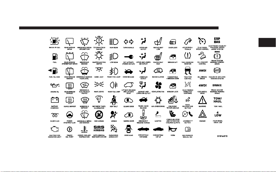
Consult the following table for a description of the
symbols that may be used on your vehicle or throughout
this Owner’s Manual:
Page 6
INTRODUCTION 5
1
Page 7
6 INTRODUCTION
WARNINGS AND CAUTIONS
This manual contains WARNINGS against operating
procedures, which could result in an accident or bodily
injury. It also contains CAUTIONS against procedures,
which could result in damage to your vehicle. If you do
not read this entire manual, you may miss important
information. Observe all Warnings and Cautions.
VEHICLE IDENTIFICATION NUMBER
The vehicle identification number (VIN) is on the left
front corner of the instrument panel. The VIN is visible
from outside the vehicle through the windshield. This
number also appears on the Automobile Information
Disclosure Label affixed to a windowonyourvehicle, the
vehicle registration, and the title.
Vehicle Identification Number
NOTE: It is illegal to remove the VIN.
Page 8

VEHICLE MODIFICATIONS / ALTERATIONS
WARNING!
Any modifications or alterations to this vehicle could
seriously affect its roadworthiness and safety and
may lead to an accident resulting in serious injury or
death.
INTRODUCTION 7
1
Page 9

Page 10

THINGS TO KNOW BEFORE STARTING YOUR VEHICLE
CONTENTS
m A Word About Your Keys ..................12
▫ Ignition Key Removal ...................12
▫ Key-In-Ignition Reminder ................13
m Security Alarm System ....................13
▫ Rearming Of The System .................13
▫ To Arm The System .....................13
▫ To Disarm The System ...................15
m Illuminated Entry System ..................16
2
m Remote Keyless Entry .....................17
▫ To Unlock The Doors ...................17
▫ To Lock The Doors .....................18
▫ To Unlatch The Trunk/Liftgate .............19
▫ Using The Panic Alarm ..................19
▫ Programming Additional Transmitters ........20
▫ Battery Replacement ....................21
▫ General Information ....................22
Page 11

10 THINGS TO KNOW BEFORE STARTING YOUR VEHICLE
m Door Locks ............................23
▫ Manual Door Lock .....................24
▫ Power Door Locks .....................24
m Windows .............................26
▫ Power Windows .......................26
▫ Auto Down Feature ....................27
▫ Wind Buffeting ........................27
m Liftgate — Coupe Models Only ..............28
m Trunk Lock And Release — Convertible
Models Only ...........................29
m Trunk Safety Warning — Convertible
Models Only ...........................30
▫ Trunk Emergency Release ................30
m Occupant Restraints ......................31
▫ Lap/Shoulder Belts .....................31
▫ Lap/Shoulder Belt Untwisting Procedure .....35
▫ Enhanced Seat Belt Reminder System
(BeltAlertt) ..........................36
▫ Automatic Locking Mode ................37
▫ Six-Point Belt System - If Equipped .........38
▫ Seat Belts And Pregnant Women ............39
▫ Seat Belt Extender ......................39
▫ Driver And Passenger Supplemental Restraint
System (SRS) - Airbag ...................40
▫ Child Restraint ........................50
Page 12

THINGS TO KNOW BEFORE STARTING YOUR VEHICLE 11
m Break-In Recommendations .................56
m Safety Tips ............................57
▫ Exhaust Gas ..........................57
▫ Safety Checks You Should Make Inside
The Vehicle ..........................58
▫ Periodic Safety Checks You Should Make
Outside The Vehicle ....................59
2
Page 13
12 THINGS TO KNOW BEFORE STARTING YOUR VEHICLE
A WORD ABOUT YOUR KEYS
You can insert the double-sided keys into the locks with
either side up.
The dealer that sold you your new vehicle has the key
code numbers for your vehicle locks. These numbers can
be used to order duplicate keys from your dealer or a
locksmith. Ask your dealer for these numbers and keep
them in a safe place.
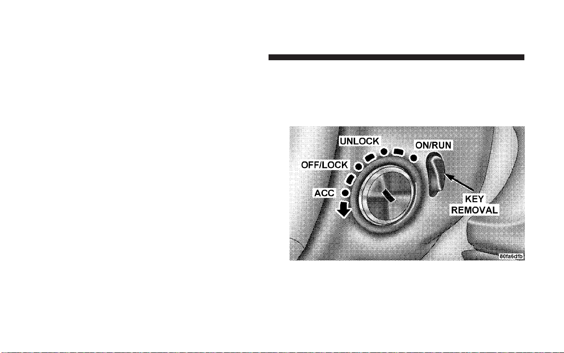
Ignition Key Removal
1. Press the clutch pedal to the floor.
2. Bring the vehicle to a stop.
3. Place the gear selector in gear.
4. Apply the parking brake fully.
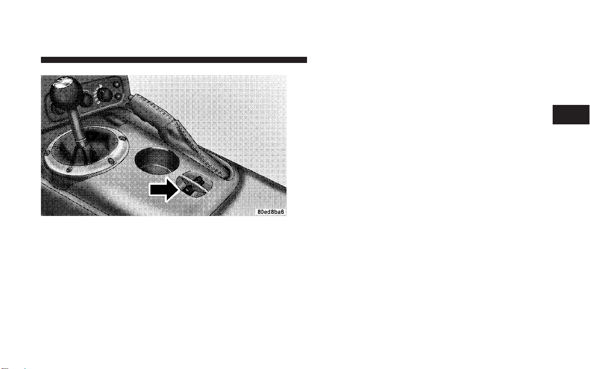
5. Press the “Key Removal” release button, turn the key
to place the ignition switch in the OFF/LOCK position,
and then pull the key out of the switch.
6. Release the clutch pedal.
Ignition Key Positions
Page 14

THINGS TO KNOW BEFORE STARTING YOUR VEHICLE 13
NOTE: The Power Accessory Delay feature allows you
to operate the radio and the power windows for 2
minutes after turning off the ignition switch. Removing
the key from the ignition switch and opening the driver’s
door will cancel this feature. Your dealership can enable
or disable the Power Accessory Delay feature as desired.
Key-In-Ignition Reminder
If you open the driver’s door when the key is in the
ignition, a chime will sound to remind you to remove the
key.
NOTE: The Key-In-Ignition reminder only sounds
when the ignition switch is placed in the OFF/LOCK or
ACC positions.
SECURITY ALARM SYSTEM
This system monitors the doors, trunk/liftgate, and hood
for unauthorized entry and the ignition switch for unauthorized operation. If something triggers the alarm, the
system will prevent the vehicle from starting. It will also
sound the horn and flash the park lights, the taillights,
and the fog lights.
Rearming of the System:
If something triggers the alarm, and no action is taken to
disarm it, the system will turn off the horn after 3
minutes, turn off all of the visual signals (flashing lights)
after 15 minutes, and then rearm itself.
To Arm the System:
Remove the key from the ignition switch and either press
a power door lock switch while the driver or passenger
door is open or press the LOCK button on the Remote
2
Page 15
14 THINGS TO KNOW BEFORE STARTING YOUR VEHICLE
Keyless Entry (RKE) transmitter. After the last door is
closed, or if all doors are closed, the system will arm itself
in approximately 16 seconds. During the arming process,
the Vehicle Security Alarm Indicator light will flash at a
fast rate. Once the system is armed, the light will flash
once every 6 seconds.
Vehicle Security Alarm Indicator Light
NOTE:
•
The system will not cancel the arming process if you
open the hood or trunk/liftgate. It will however cancel
the arming process if you open a door or turn on the
ignition. If this occurs, and you wish to rearm the
system, simply repeat either of the previously described arming sequences.
•
The Vehicle Security Alarm Indicator light will remain
on steady if the hood or trunk/liftgate is open during
the arming process or if there is a fault in the system.
If you verify that the hood and trunk/liftgate are not
open, and the light remains on steady, see your
authorized dealer for service.
Entering the Trunk with the System Armed —
Convertible:
NOTE: Using the key to open the trunk while the
system armed will trigger the alarm.
Page 16
THINGS TO KNOW BEFORE STARTING YOUR VEHICLE 15
Press the Trunk button on the RKE transmitter to allow
access without triggering the alarm or having to disarm
the system. The trunk lid will pop open.
Entering the liftgate with the System Armed —
Coupe:
NOTE: Using the key to open the liftgate while the
system armed will trigger the alarm.
Press the Liftgate button on the RKE transmitter to allow
access without triggering the alarm or having to disarm
the system. Then, within 30 seconds, open the liftgate by
using the key cylinder or the liftgate release switch
located in the exterior liftgate handle.
NOTE: If you do not open the liftgate within 30 seconds,
the system will re-arm and ignore the switch input.
After closing the liftgate, the system will arm immediately without having to re-lock the vehicle.
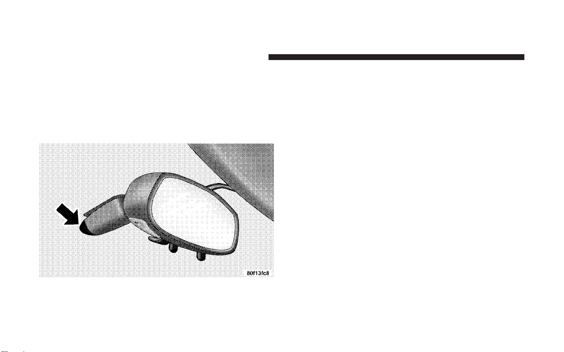
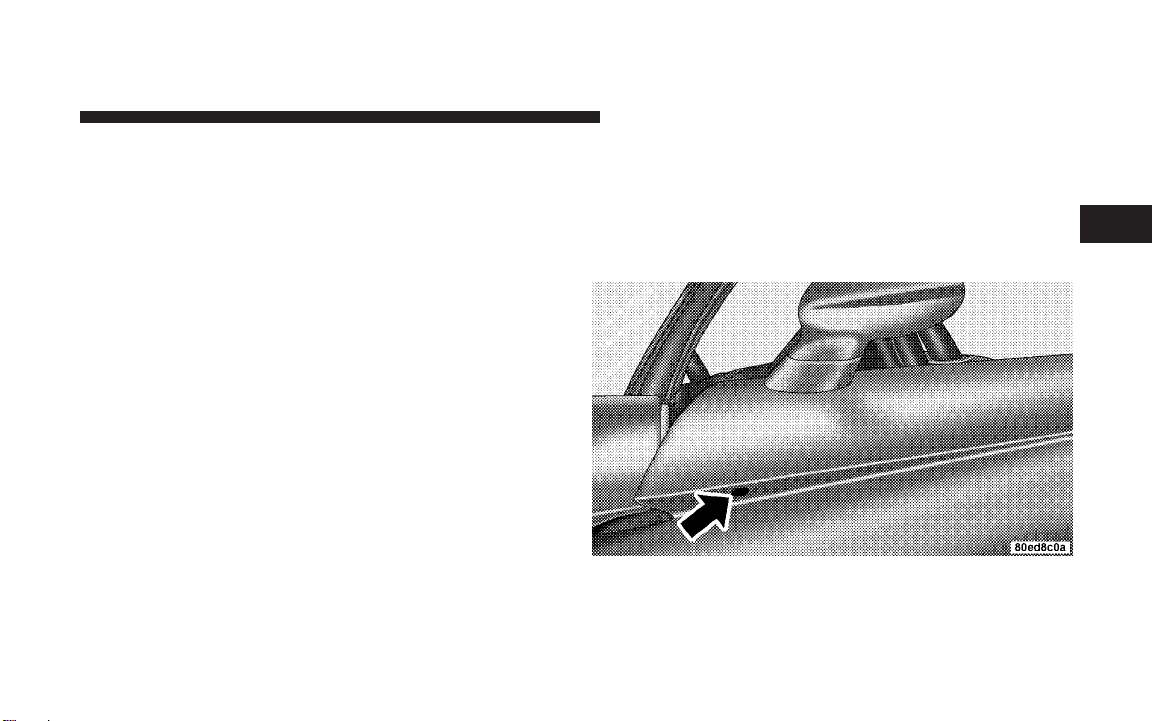
To Disarm the System
There are two ways to disarm the system:
•
Use the key to unlock the driver’s door. The door lock
is located on the outside door panel beneath the
mirror.
Mechanical Door Lock
2
Page 17

16 THINGS TO KNOW BEFORE STARTING YOUR VEHICLE
•
Press the UNLOCK button on the RKE transmitter.
The front and rear park lights and the turn signal
lights will flash to acknowledge the signal.
NOTE: The vehicle will not start unless the Vehicle
Security Alarm System is disarmed by either method.
Inserting the key in the ignition WILL NOT disarm the
system. Furthermore, turning the ignition key to any
position while the system is armed will trigger an alarm.
Tamper Alert
If something has triggered the system in your absence,
the Vehicle Security Alarm Indicator Light will flash
twice every six seconds. In addition, the horn will sound
three times when you disarm the system.
ILLUMINATED ENTRY SYSTEM
The interior lights will turn on whenever a door is
opened or the liftgate is opened (Coupe models) and the
dimmer switch is not in the defeat position.
The interior lights will turn on, remain on for about 30
seconds, and then fade to off if any of the following
occur:
•
A door is opened using the outside door handle and
then closed.
•
A door is unlocked using the remote keyless entry
transmitter.
•
A door is unlocked using the outside driver’s door key
cylinder.
The interior lights will turn on and remain on for about 4
seconds and then fade to off if a door is opened using the
inside door handle.
Page 18

THINGS TO KNOW BEFORE STARTING YOUR VEHICLE 17
REMOTE KEYLESS ENTRY
This system allows you to lock or unlock the doors, open
the trunk/liftgate, or activate the panic alarm from
distances up to about 23 feet (7 meters) using a hand held
radio transmitter. The transmitter need not be pointed at
the vehicle to activate the system.
Keyless Entry Transmitter
To Unlock the Doors:
Press and release the UNLOCK button on the transmitter
once to unlock the driver’s door, or twice to unlock both
doors. The park lights and turn signal lights will flash to
acknowledge the signal and the illuminated entry system
will turn on. In addition, the words DOOR UNLOCKED
will flash in the odometer if one door is unlocked or will
remain on steadily if both doors are unlocked.
NOTE: On Coupe models, pressing either the UNLOCK
button or the LIFTGATE button will allow liftgate access.
Remote Key Unlock, Driver Door/Both Doors First
This feature lets you program the system to unlock either
the driver’s door or both doors on the first press of the
UNLOCK button on the transmitter. To change the current setting, proceed as follows:
1. Press the UNLOCK button on a programmed transmitter for at least 4 seconds, but not longer than 10
seconds. Then, press the LOCK button.
2. Release both buttons at the same time.
3. Test the feature while outside of the vehicle, by
pressing the UNLOCK button on the transmitter with the
ignition in the OFF/LOCK position, and the key removed.
2
Page 19

18 THINGS TO KNOW BEFORE STARTING YOUR VEHICLE
4. Repeat these steps if you want to return this feature to
its previous setting.
NOTE: Pressing the LOCK button on the transmitter
while you are in the vehicle will activate the Security
Alarm. Opening a door with the SecurityAlarm activated
will cause the alarm to sound. Press the UNLOCK button
to deactivate the Security Alarm.
Flash Lights with Remote Key Lock
This feature will cause the park lights and turn signal
lights to flash when the doors are locked or unlocked
with the transmitter. This feature can be turned on or
turned off. To change the current setting, proceed as
follows:
1. Press the LOCK button on a programmed transmitter
for at least 4 seconds, but no longer then 10 seconds.
Then, press the TRUNK/LIFTGATE button.
2. Release both buttons at the same time.
3. Test the feature while outside of the vehicle, by
pressing the LOCK/UNLOCK buttons on the transmitter
with the ignition in the OFF/LOCK position, and the key
removed.
4. Repeat these steps if you want to return this feature to
its previous setting.
NOTE: Pressing the LOCK button on the transmitter
while you are in the vehicle will activate the Security
Alarm. Opening a door with the SecurityAlarm activated
will cause the alarm to sound. Press the UNLOCK button
to deactivate the Security Alarm.
To Lock the Doors:
Press and release the LOCK button on the transmitter to
lock the doors. The horn will chirp once and the park
lights and turn signal lights will flash to acknowledge the
signal.
Page 20

THINGS TO KNOW BEFORE STARTING YOUR VEHICLE 19
Sound Horn with Remote Key Lock
This feature will cause the horn to chirp when the doors
are locked with the transmitter. This feature can be
turned on or turned off. To change the current setting,
proceed as follows:
1. Press the LOCK button on a programmed transmitter
for at least 4 seconds, but no longer then 10 seconds.
Then, press the UNLOCK button.
2. Release both buttons at the same time.
3. Test the feature while outside of the vehicle, by
pressing the LOCK button on the transmitter with the
ignition in the OFF/LOCK position, and the key removed.
4. Repeat these steps if you want to return this feature to
its previous setting.
NOTE: Pressing the LOCK button on the transmitter
while you are in the vehicle will activate the Security
Alarm. Opening a door with the SecurityAlarm activated
will cause the alarm to sound. Press the UNLOCK button
to deactivate the Security Alarm.
To Unlatch the Trunk/Liftgate:
Press and hold the TRUNK/LIFTGATE button on the
transmitter for at least one second to unlatch the trunk/
liftgate. The park lights and turn signal lights will flash
three times to acknowledge the signal.
Using The Panic Alarm:
The panic alarm unlocks the driver’s door, turns on the
interior lights, flashes the park lights and fog lights, and
sounds the horn. The Panic alarm will not work when
driving the vehicle.
To turn the panic alarm ON or OFF, press and hold the
PANIC button on the transmitter for at least one second
and release. The alarm can also be turned off by inserting
the key into the ignition switch and turning it to the
2
Page 21

20 THINGS TO KNOW BEFORE STARTING YOUR VEHICLE
ON/RUN position. If not deactivated through the transmitter or the ignition switch, the alarm will turn off
automatically after 3 minutes.
Programming Additional Transmitters
NOTE: You must have at least one programmed transmitter to perform this procedure. If you do not have a
programmed transmitter, contact your dealer for details.
Use this procedure to program up to three additional
transmitters for your vehicle. To activate the programming feature, proceed as follows:
1. Turn the ignition switch to the ON/RUN position.
2. Set the parking brake.
3. Press and hold the UNLOCK button for at least 5
seconds, but no longer then 10 seconds on a previously
programmed transmitter. Then, press the PANIC button
while still holing the UNLOCK button.
4. Release both buttons at the same time. A chime will
sound to signal that the programming feature is activated.
5. Within 30 seconds, press and release the LOCK button
and the UNLOCK button at the same time on the new
transmitter.
6. Press and release any button one time on the new
transmitter. A chime will sound to indicate that the new
transmitter is programmed. An additional chime will
sound at the end of the 30-second programming period.
It will also sound if the ignition is switched OFF.
7. Repeat Steps 3 through 6 to program each additional
transmitter.
Page 22
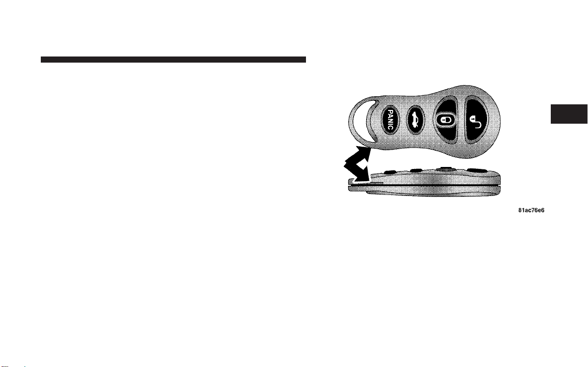
Battery Replacement
The recommended replacement battery is 2016. This is a
generic battery, readily available at local retail stores.
NOTE:
•
Perchlorate Material — special handling may apply.
See www.dtsc.ca.gov/hazardouswaste/perchlorate.
•
Do not touch the battery terminals that are on the back
housing or the printed circuit board.
1. Separate the two halves of the transmitter with a coin
or similar object.
THINGS TO KNOW BEFORE STARTING YOUR VEHICLE 21
2
Separating Transmitter Halves
Page 23

22 THINGS TO KNOW BEFORE STARTING YOUR VEHICLE
2. Remove and replace the battery. Avoid touching the
new battery with your fingers. Skin oils may cause
battery deterioration. If you touch a battery, clean it with
rubbing alcohol.
3. To assemble the transmitter case, snap the two halves
together.
4. Test the transmitter operation.
General Information
This transmitter complies with FCC rules part 15. Operation is subject to the following conditions:
1. This device may not cause harmful interference.
2. This device must accept any interference that may be
received, including interference that may cause undesired operation.
If your Remote Keyless Entry transmitter ever fails to
operate from a normal distance, check the following:
1. Closeness to a radio transmitter, such as a radio station
tower, airport transmitter, and some mobile or CB radios
can affect transmitter operation. To verify if this is the
cause, move the vehicle to another area and test transmitter operation.
2. The transmitter may become “out of sync” and will no
longer function if operated morethan 255 times while out
of range of the vehicle (23 feet or 7 meters) or if operated
while the vehicle battery is dead or disconnected. To
“synchronize” the transmitter, remove the key from the
ignition. Close the hood and all doors. Press both buttons
on the transmitter for about 10 seconds. The horn will
chirp once to acknowledge the signal. Normal transmitter operation should resume.
3. The transmitter battery may be weak or dead. The
expected life of the battery is a minimum of three years.
Page 24
THINGS TO KNOW BEFORE STARTING YOUR VEHICLE 23
DOOR LOCKS
WARNING!
Do not touch the exhaust pipe sill covers when
entering or exiting your Viper. They can be hot
enough to burn you. Observe the warning labels on
each door closure panel.
WARNING!
•
For personal security and safety in the event of an
accident, lock the vehicle doors as you drive as
well as when you park and leave the vehicle.
•
When leaving the vehicle always remove the key
from the ignition lock, and lock your vehicle.
Unsupervised use of vehicle equipment may cause
severe personal injuries and death.
•
Never leave children alone in a vehicle. Leaving
children in a vehicle unattended is dangerous for a
number of reasons. A child or others could be
injured seriously or fatally. Don’t leave the keys in
the ignition. A child could operate power windows, other controls, or move the vehicle.
2
Page 25
24 THINGS TO KNOW BEFORE STARTING YOUR VEHICLE
Manual Door Lock
The driver’s door can be locked or unlocked with the key.
The door lock is located on the outside door panel
beneath the mirror.
Mechanical Door Lock
Power Door Locks
A power door lock switch is on each door trim panel. Use
this switch to lock or unlock the doors.
Power Door Lock Switch
NOTE: To prevent you from accidentally locking your
keys in the vehicle, the power door locks will not operate
if the key is in the ignition and the driver’s door is open.
Page 26

THINGS TO KNOW BEFORE STARTING YOUR VEHICLE 25
Electronic Door Lock
This vehicle is equipped with a virtual lock system. Input
from the outside door handle is ignored if the vehicle is
virtually locked.
Door Lock Messaging
The words “DOOR UNLOCKED” will flash in the odometer if one door is unlocked or will remain on steadily if
both doors are unlocked. A door is considered unlocked
if the inside door handle is pulled. With the key in the
ignition switch, this display will turn off approximately
40 seconds after switching off the ignition, or ifthePower
Accessory Delay feature is active, it will turn off approximately 40 seconds after the delay feature times out.
Automatic Door Locks
This feature locks the doors automatically once vehicle
speed reaches 18 mph (29 km/h).
NOTE: Input from the door handles is ignored once the
vehicle is moving faster than 5 mph.
Automatic Door Locks Programming
The Automatic Door Locks feature can be enabled or
disabled as follows:
1. Close all doors and place the key in the ignition.
2. Cycle the ignition switch between ON/RUN and
OFF/LOCK 4 times ending up in the OFF/LOCK position.
3. Depress the power door lock switch to lock the doors.
4. A single chime will indicate the completion of the
programming.
5. Repeat these steps if you want to return this feature to
its previous setting.
This feature can also be disabled at the dealership if
desired.
NOTE: Use the Automatic Door Locks feature in accordance with local laws.
2
Page 27

26 THINGS TO KNOW BEFORE STARTING YOUR VEHICLE
WINDOWS
Power Windows
The power window switches are located between the
driver and passenger seats on the centertunnelbezel, just
to the left of the parking brake. The switch on the left side
controls the driver’s window and the switch on the right
controls the passenger’s window. The power window
switches are active when the ignition is in ON/RUN or
ACC position.
NOTE:
•
The Power Accessory Delay feature allows you to
operate the power windows for 2 minutes after turning off the ignition switch. Removing the key from the
ignition switch and opening the driver’s door will
cancel this feature. Your dealership can enable or
disable the Power Accessory Delay feature as desired.
•
Windows cannot be driven up during Power Accessory Delay with a door open. Furthermore, opening
the door will stop the windowmovementimmediately
if the window is in the process of going up.
•
The window will lower slightly if it is closed completely when opening the door. The window will
return to its fully closed position after closing the door.
This action is necessary in order to clear the seal when
opening the door.
WARNING!
Never leave children in a vehicle, with the keys in the
ignition switch. Occupants, particularly unattended
children, can become entrapped by the power windows while operating the power window switch. Such
entrapment may result in serious injury or death.
Page 28
Power Window Switches
THINGS TO KNOW BEFORE STARTING YOUR VEHICLE 27
Auto Down Feature
Both windows have an auto down feature. Press the
window switch to the second detent, release, and the
window will go down automatically. Press the switch a
second time in either direction to stop the window.
To open the window to a desired position, press and hold
the window switch in the first detent. Release the switch
when you want the window to stop.
Wind Buffeting
Wind buffeting can be described as the perception of
pressure on the ears or a helicopter-type sound in the
ears. Your vehicle may exhibit wind buffeting with the
windows down, or the top down (convertible models).
This is a normal occurrence and can be minimized by
adjusting one or both windows up or down slightly.
2
Page 29

28 THINGS TO KNOW BEFORE STARTING YOUR VEHICLE
LIFTGATE — COUPE MODELS ONLY
The liftgate can be unlocked or locked by the Remote
Keyless Entry (RKE) transmitter or by activating either of
the power door lock switches located on the door trim
panels.
To unlock the liftgate with the RKE transmitter, press the
LIFTGATE button on the transmitter for at least one
second. The park lights and turn signal lights will flash
three times to acknowledge the signal.
NOTE: Pressing the UNLOCK button on the transmitter
will also allow liftgate access.
Once unlocked, the liftgate can be opened or closed. To
open the liftgate, depress the liftgate release switch
located in the exterior liftgate handle and pull the liftgate
open with one fluid motion.
NOTE: The liftgate release switch will be ignored under
the following conditions:
•
When the ignition is in RUN and the parking brake is
not set.
•
When vehicle speed is not a 0 mph (0 km/h).
•
When all doors are locked (except for RKE liftgate
access). Refer to “Entering the liftgate with the System
Armed — Coupe” under “Security Alarm System” in
this section for additional information.
The word “DECK” will flash in the odometer when the
liftgate is open. With the key in the ignition switch, this
display will turn off approximately 40 seconds after
switching off the ignition, or if the Power Accessory
Delay feature is active, it will turn off approximately 40
seconds after the delay feature times out.
Page 30

THINGS TO KNOW BEFORE STARTING YOUR VEHICLE 29
WARNING!
•
Driving with the liftgate open can allow poisonous exhaust gases into your vehicle. You and your
passengers could be injured by these fumes. Keep
the liftgate closed when you are operating the
vehicle.
•
If you are required to drive with the liftgate open,
make sure that all windows are closed, and the
climate control blower switch is set at high speed.
DO NOT use the recirculation mode.
Gas props support the liftgate in the open position.
However, because the gas pressure drops with temperature, it may be necessary to assist the props when
opening the liftgate in cold weather.
TRUNK LOCK AND RELEASE — CONVERTIBLE
MODELS ONLY
You can unlatch the trunk lid by pressing the TRUNK
button on the Remote Keyless Entry (RKE) transmitter
for at least one second. The park lights and turn signal
lights will flash three times to acknowledge the signal
and the trunk lid will pop open.
You can also unlatch the trunk lid with the key. The key
cylinder is located on the trunk lid.
The word “DECK” will flash in the odometer when the
trunk lid is open. With the key in the ignition switch, this
display will turn off approximately 40 seconds after
switching off the ignition, or if the Power Accessory
Delay feature is active, it will turn off approximately 40
seconds after the delay feature times out.
2
Page 31

30 THINGS TO KNOW BEFORE STARTING YOUR VEHICLE
NOTE: Gas props support the trunk lid in the open
position. However, because the gas pressure drops with
temperature, it may be necessaryto assist the props when
opening the trunk lid in cold weather.
TRUNK SAFETY WARNING — CONVERTIBLE
MODELS ONLY
WARNING!
Do not allow children to have access to the trunk,
either by climbing into the trunk from outside, or
through the inside of the vehicle. Always close the
trunk lid when your vehicle is unattended. Once in
the trunk, young children may not be able to escape.
If trapped in the trunk, children can die from suffocation or heat stroke.
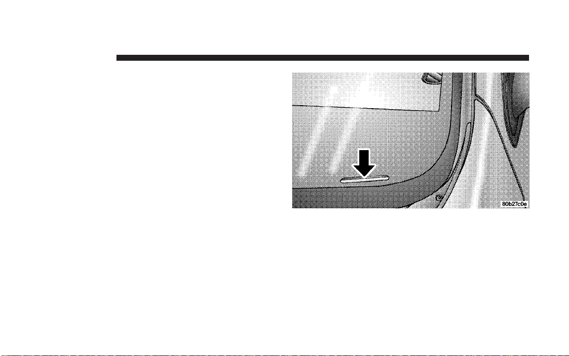
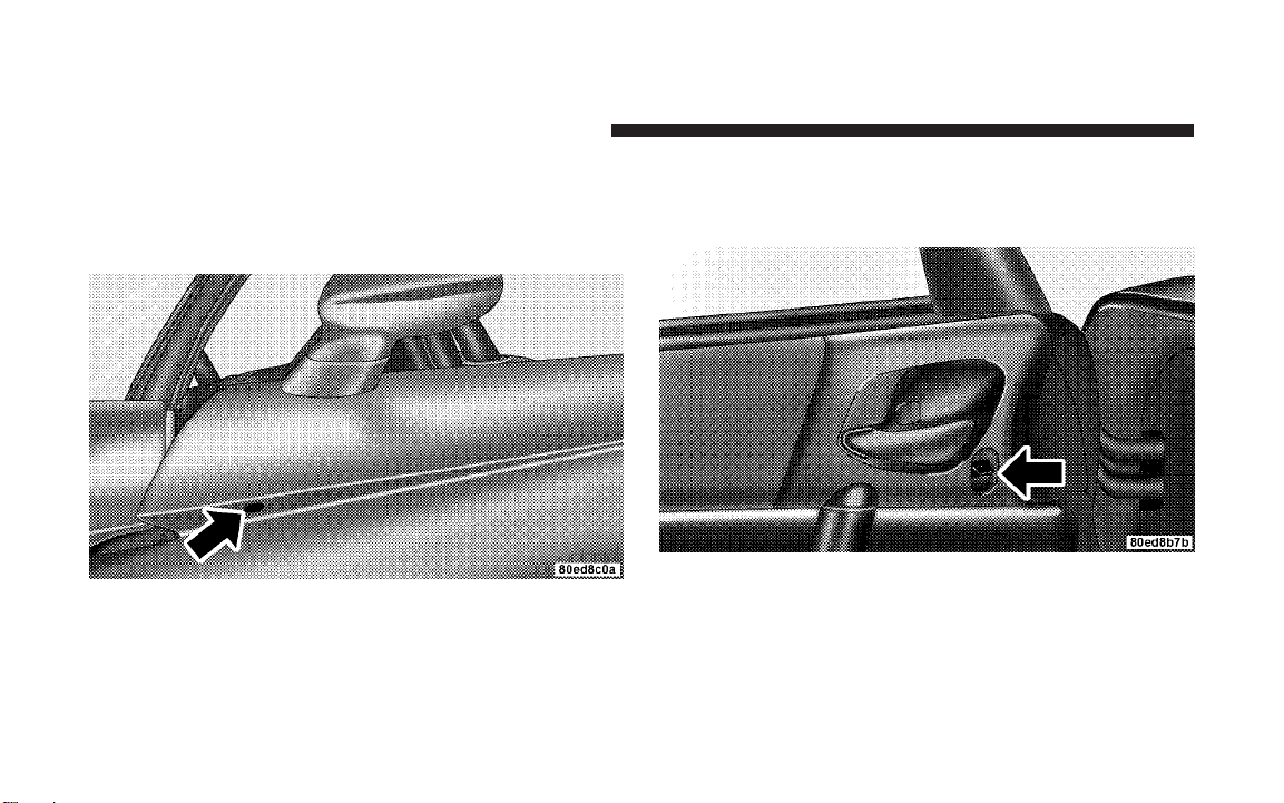
Trunk Emergency Release
Emergency Release
The trunk of your vehicle is equipped with an emergency
release handle. It is located on the inside of the trunk lid,
near the latch, and iscoatedso that it glows in a darkened
trunk. Pull on the handle to open the trunk.
Page 32

THINGS TO KNOW BEFORE STARTING YOUR VEHICLE 31
OCCUPANT RESTRAINTS
Some of the most important safety features in your
vehicle are the restraint systems. These include the seat
belts and the airbags for the driver and passenger.
Please pay close attention to the information in this
section. It explains how to use your restraint system
properly to keep you and your passenger as safe as
possible. Note that all of the warnings in this section
apply no matter which system you have.
WARNING!
In a collision, you and your passenger can suffer
much greater injuries if you are not buckled up
properly. Youcanstrikethe interior of your vehicle or
your passenger, or you can be thrown out of the
vehicle. Always be sure you and your passenger are
buckled up properly.
Buckle up even though you are an excellent driver, even
on short trips. Someone on the road may be a poor driver
and cause a collision that includes you. This can happen
far away from home or on your street.
Research has shown that seat belts save lives. They also
can reduce the seriousness of injuries in a collision. Some
of the worst injuries happen when people are thrown
from the vehicle. Seat belts reduce the possibility of
ejection and the risk of injury caused by striking the
inside of the vehicle. Everyone in a motor vehicle should
be belted at all times.
Lap/Shoulder Belts
Each seat belt is a combined lap/shoulder belt system.
The belt webbing retractor will lock only during very
sudden stops or impacts. Thisfeature allows the shoulder
portion of the belt to move freely with you under normal
conditions. However, in a collision, the belt will lock and
reduce your risk of striking the inside of the vehicle or
being thrown out.
2
Page 33

32 THINGS TO KNOW BEFORE STARTING YOUR VEHICLE
WARNING!
• It is extremelydangerous to ride in a cargo area, inside or
outside of a vehicle. In a collision, people riding in these
areas are more likely to be injured seriously or killed.
• Do not allow people to ride in any area of your vehicle
that is not equipped with seats and seat belts.
• Be sure everyone in your vehicle is in a seat and using a
seat belt properly.
• Wearing a seat belt incorrectly is dangerous. Seat belts
are designed to go around the large bones of your body.
These are the strongest parts of your body and can take
the forces of a collision the best.
• Wearing your belt in the wrong place could make your
injuries in a collision much worse. You might suffer
internal injuries, or you could even slide out of part of
the belt. Follow these instructions to wear your seat belt
safely and to keep your passengers safe, too.
• Twopeople should never be beltedinto a singleseat belt.
People belted together can crash into one another in an
accident, hurting one another badly. Never use a lap/
shoulder belt or a lap belt for more than one person, no
matter what their size.
Lap/Shoulder Belt Operating Instructions
1. Enter the vehicle and close the door. Sit back and
adjust the seat.
2. The seat belt latch plate is located at the side of your
seat back. Grasp the latch plate and pull out the belt.
Latch Plate (Convertible Shown)
Page 34

THINGS TO KNOW BEFORE STARTING YOUR VEHICLE 33
3. Slide the latch plate up the webbing as far as necessary
to make the belt go around your lap.
4. When the belt is long enough to fit, insert the latch
plate into the buckle until you hear a “click.”
Latch Plate To Buckle (Convertible Shown)
WARNING!
• A belt that is buckled into the wrong buckle will not
protect you properly. The lap portion could ride too
high on your body, possibly causing internal injuries.
Always buckle your belt into the buckle nearest you.
• Abelt that is too loose will not protect you as well. In
a sudden stop, you could move too far forward, increasing the possibility of injury. Wear your seat belt snugly.
• Abelt that is worn under your arm is very dangerous.
Your body could strike the inside surfaces of the
vehicle in a collision, increasing head and neck injury.
A belt worn under the arm can cause internal injuries.
Ribs aren’t as strong as shoulder bones. Wear the belt
over your shoulder so that your strongest bones will
take the force in a collision.
• A shoulder belt placed behind you will not protect
you from injury during a collision. You are more likely
to hit your head in a collision if you do not wear your
shoulder belt.The lap and shoulderbelt are meant tobe
used together.
2
Page 35

34 THINGS TO KNOW BEFORE STARTING YOUR VEHICLE
5. Position the lap belt across your thighs, below your
abdomen. To remove slack in the lap belt portion, pull up
a little on the shoulder belt, as shown.
Removing Slack From Belt (Convertible Shown)
6. To loosen the lap belt if it is too tight, lift up on the
shoulder belt and pull on the lap belt.A snug belt reduces
the risk of sliding under the belt in a collision.
WARNING!
• A lap belt worn too high can increase the risk of
internal injury in a collision. The belt forces won’t be
at the strong hip and pelvic bones, but across your
abdomen. Always wear the lap belt as low as possible and keep it snug.
• Atwisted belt can’t do its job as well. In a collision,
it could even cut into you. Be sure the belt is straight.
If you can’t straighten a belt in your vehicle, take it to
your dealer and have it fixed.
7. Position the shoulder belt on your chest so that it is
comfortable and not resting on your neck. The retractor
will withdraw any slack in the belt.
Page 36

THINGS TO KNOW BEFORE STARTING YOUR VEHICLE 35
8. To release the belt, push the red button in the buckle.
The belt will retract automatically to its stowed position.
If necessary, slide the latch plate down the webbing to
allow it to retract fully.
WARNING!
A frayed or torn belt could rip apart in a collision and
leave you with no protection. Inspect the belt system
periodically, checking for cuts, frays, or loose parts.
Damaged parts must be replaced immediately. Do
not disassemble or modify the system. Seat belt
assemblies must be replaced after a collision if they
have been damaged (bent retractor, torn webbing,
etc.).
Lap/Shoulder Belt Untwisting Procedure
Use the following procedure to untwist a twisted lap/
shoulder belt.
1. Position the latch plate as close as possible to the
anchor point.
2. At about 6 to 12 inches (15 to 30 cm) above the latch
plate, grasp and twist the belt webbing 180° to create a
fold that begins immediately above the latch plate.
3. Slide the latch plate upward over the folded webbing.
The folded webbing must enter the slot at the top of the
latch plate.
4. Continue to slide the latch plate up until it clears the
folded webbing.
2
Page 37

36 THINGS TO KNOW BEFORE STARTING YOUR VEHICLE
Enhanced Seat Belt Reminder System (BeltAlertT)
If the driver does not buckle their seat belt and vehicle
speed exceeds 5 mph (8 km/h), or if the passenger does
not buckle their seat belt within 10 seconds of vehicle
speed exceeding 5 mph (8 km/h), the Enhanced Warning
System (Belt Alert) will alert the occupant(s) to buckle
their seat belt(s). Once triggered, the Enhanced Warning
System (Belt Alert) will flash the Seat Belt Reminder light
and chime for up to 96 seconds to alert the occupant(s) to
buckle their seat belt(s). If the driver unbuckles their seat
belt while vehicle speed is greater than 5 mph (8 km/h),
or if the passenger unbuckles their seat belt for more than
10 seconds while vehicle speed is greater than 5 mph (8
km/h), the Enhanced Warning System (Belt Alert) will
reactivate.
BeltAlertt Programming
The Enhanced Warning System (BeltAlertt) can be enabled or disabled by your authorized dealer or by
performing the following steps:
NOTE: DaimlerChrysler does not recommend deactivating the Enhanced Warning System (BeltAlertt).
1. Close all doors.
2. Turn the ignition switch to the OFF/LOCK position.
3. Buckle the driver’s seat belt.
4. Turn the ignition switch to the ON/RUN position, but
do not start the engine. Wait for the Seat Belt Reminder
light to turn off and then proceed to the next step.
NOTE: You must perform the following steps within 60
seconds of turning the ignition switch to the ON/RUN
position.
5. Within 60 seconds of turning the ignition switch to the
ON/RUN position, unbuckle and then re-buckle the
driver’s seat belt at least three times within 10 seconds,
ending with the seat belt buckled.
Page 38

THINGS TO KNOW BEFORE STARTING YOUR VEHICLE 37
NOTE: Watch fortheSeat Belt Reminder light to turn on
while unbuckling the seat belt and turn off while rebuckling the seat belt. It may be necessary to retract the
seat belt.
6. Turn the ignition switch to the OFF/LOCK position. A
single chime will sound to signify that you have completed the programming successfully.
The Enhanced Warning System (BeltAlertt) can be reactivated by repeating this procedure.
NOTE: When the Enhanced Warning System
(BeltAlertt) is deactivated, the Seat Belt Reminder light
will continue to illuminate as long as the driver’sseatbelt
or the passenger’s seat belt is unbuckled.
Automatic Locking Mode
The seat belts for both occupants are equipped with
emergency locking retractors for normal use. Emergency
locking retractors activate during very sudden stops or
impacts. The passenger seat belt in your vehicle can also
be converted to an automatic locking retractor to secure
child restraint systems. Seat belts equipped with automatic locking retractors have a distinctive label on the
webbing.
How To Engage The Automatic Locking Mode
To convert the passenger seat belt from emergency locking mode to automatic locking mode, grasp the shoulder
portion of the belt and pull all of the webbing out of the
retractor. Then, allow some of the webbing to retract back
into the retractor. As the belt retracts, you will hear a
clicking sound indicating that the belt is now in automatic locking mode.
2
Page 39

38 THINGS TO KNOW BEFORE STARTING YOUR VEHICLE
NOTE: Once the belt is in automatic locking mode, you
will not be able to pull any more of the webbing out of
the retractor. In this mode, you will only be able to retract
excess webbing into the retractor to secure the child
restraint.
How To Disengage The Automatic Locking Mode
Simply allow all of the webbing to retract back into the
retractor to disengage the automatic locking mode. This
will return the retractor to the emergency locking mode
for normal use.
Six-Point Belt System - If equipped
This six-point belt system meets SCCA standards and it
should only be used when engaging in performance
related driving events. In turn, the standard lap/
shoulder belt should be used whenever the vehicle is
operated on the street.
Six-Point Belt Operating Instructions
1. Place the anti-submarining belt on the seat so that it
points upward.
2. Buckle the left and right lap belts and strap both legs.
3. Buckle the left and right shoulder belts.
4. Adjust the belts by pulling on the web ends and/or
repositioning the web clips and straps as required.
5. To release the belts, turn the belt latch mechanism
1
turn in either the clockwise or the counter-clockwise
direction.
NOTE: The anti-submarining belt and the shoulder belt
are attached to eye bolts at designated locations and they
should be removed from the vehicle when not in use. The
lap belts and straps can be stored behind or to the side of
the seat after removal.
⁄
4
Page 40

THINGS TO KNOW BEFORE STARTING YOUR VEHICLE 39
Seat Belts and Pregnant Women
We recommend that pregnant women use the seat belts
throughout their pregnancy. Keeping the mother safe is
the best way to keep the baby safe.
Pregnant women should wear the lap portion of the belt
across the thighs and as snug across the hips as possible.
Keep the belt low so that it does not come across the
abdomen. That way the strong bones of the hips will take
the force if there is a collision.
Seat Belt Extender
If a seat belt is too short, even when extended fully, your
dealer can provide you with a seat belt extender. This
extender should only be used if the existing belt is not
long enough. When it is not required, remove the extender, and store it.
WARNING!
Using a seat belt extender when not needed can
increase the risk of injury in a collision. Only use
when the seat belt is not long enoughwhenitis worn
low and snug, and in the recommended seating
positions. Remove and store the extender when not
needed.
2
Page 41

40 THINGS TO KNOW BEFORE STARTING YOUR VEHICLE
Driver and Passenger Supplemental Restraint System (SRS) - Airbag
This vehicle is equipped with airbags for the driver and
passenger as a supplement to the seat belt restraint
systems. The driver airbag is mounted in the steering
wheel. The passenger airbag is mounted underneath a
cover in the passenger’s side of the instrument panel. The
words SRS/AIRBAG is embossed on the airbag covers.
NOTE: The airbags are certified to the Federal regulations that allow less forceful deployment. The passenger
airbag is certified to the Federal regulations that define
Occupant Classification (Refer to “How The Airbag System Works” in this section).
The airbags have a multi stage inflator design. This may
allow the airbag to have different rates of inflation that
are based on collision severity and occupant size.
WARNING!
• Do not put anything on or around the airbag covers or
attempt to open them manually. You may damage the
airbags and you could be injured because the airbags are
no longer functional. These protective covers for the
airbag cushions are designed to open only when the
airbags are inflating.
• Do not drill, cut, or tamper with the knee bolster in any
way.
• Do not mount any accessories to the knee bolster such as
alarm lights, stereos, citizens band radios, etc.
• Relying on the airbags alone could lead to more severe
injuries in a collision. The airbags work with your seat
belt to restrain you properly. In some collisions, the
airbags won’t deploy at all. Always wear your seat belts
even though you have airbags.
• Being too close tothe steering wheel or instrumentpanel
during airbag deployment could cause serious injury.
Airbags need room to inflate. Sit back, extending your
arms comfortably to reach the steering wheel or instrument panel.
Page 42

THINGS TO KNOW BEFORE STARTING YOUR VEHICLE 41
The airbags work withtheinstrument panel knee bolsters
and the seat belts to provide improved protection for the
driver and passenger.While the seat belts are designed to
protect the driver and passenger in many types of
collisions, the airbags will deploy in moderate to severe
frontal collisions. However, even in collisions where the
airbags deploy, all occupants need the seat belts to keep
them in the right position for the airbags to protect
properly.
NOTE: The passenger airbag may not deploy if the
Occupant Classification System (refer to “How The Airbag System Works” in this section) determines the seat is
empty or is occupied by someone that is classified in the
“child” category. This could be a child, a teenager, or
even a small adult. Therefore, even if the driver airbag
deploys, the passenger airbag may not deploy.
Here are some simple steps you can take to minimize
the risk of harm from a deploying airbag.
1. An infant up to 1 year or approximately 20 pounds (9
kg) should never ride in the vehicle, because in the event
of a crash the rear facing child seat places them too close
to the passenger airbag.
2. An infant in rear facing child safety seat, designed for
a child up to one year or approximately 20 pounds (9 kg),
should NEVER ride in the front seat of a vehicle
equipped with a passenger airbag, unless the airbag is
shut OFF. An airbag deployment can cause severe injury
or death to an infant in this position. Refer to “Passenger
Airbag Disabled (PAD) Indicator Light” in this section.
3. A child that is not big enough to wear the vehicle seat
belt properly (refer to information on Child Restraint in
this section) should be secured in a child safety seat or
booster seat.
4. An older child who does not use a child safety seat or
booster seat should ride buckled properly in their seat.
2
Page 43

42 THINGS TO KNOW BEFORE STARTING YOUR VEHICLE
5. Never allow a child to place the shoulder belt behind
them or under the arm.
6. Never allow a child to lean forward toward the
instrument panel as a passenger airbag deployment
could cause severe injury or death to a child in this
position.
7. For a child from 1 to 12 years old: Move the passenger
seat as far back as possible. For a child from 20 to 60
pounds (9 kg to 27 kg): Secure them in the appropriate
child safety seat or booster seat. If too large for a booster
seat, the child should wear the lap/shoulder belt properly.
8. Read the instructions provided with your child restraint to make sure that you are using it properly.
9. Read the instructions provided with your child safety
seat or booster seat to make sure that you are using it
properly.
10. All occupants should wear their lap and shoulder
belts properly.
11. Position the driver seat and passenger seat as far
away from the instrument panel as practical to allow the
airbags room to inflate. Note that the power adjustable
pedals allow for more driver’s seat adjustment options.
Refer to “Adjustable Pedals” in Section 3 of this manual
for details.
Airbag System Components
The airbag system consists of the following:
•
Occupant Restraint Controller (ORC)
•
Airbag Warning Light
•
Driver Airbag
•
Passenger Airbag
•
Passenger Airbag Off Light
Page 44

•
Steering Wheel and Column
•
Instrument Panel
•
Seat Track Position Sensors
•
Interconnecting Wiring
•
Seat Belt Reminder Light
•
Knee Impact Bolsters
•
Front Acceleration Sensors
•
Passenger Seat Occupant Classification System (OCS)
−
Occupant Classification Module (OCM)
−
Passenger Airbag Disabled (PAD) Indicator Light
−
Flex Mat
−
Interconnecting Wiring
−
Seat Track Position Sensors
THINGS TO KNOW BEFORE STARTING YOUR VEHICLE 43
How The Airbag System Works
The Occupant Restraint Controller (ORC) determines
•
if a frontal collision is severe enough to require the
airbags to inflate. The airbag inflators are designed to
provide different rates of inflation. Based on the level
of collision severity, the ORC determines the proper
rate of inflation. The ORC may modify the rate of
passenger airbag inflation or prevent passenger airbag
deployment based on input from the Occupant Classification System (OCS). The ORC will not detect roll
over or rear impacts. Furthermore, the airbags are not
on and will not inflate if the key is in the OFF/LOCK
position, in the ACC position, or not in the ignition.
The ORC also monitors the readiness of the electronic
parts of the system whenever the ignition switch is in
the ON/RUN position. These include all of the items
listed under “Airbag System Components” except the
steering wheel and column and the knee bolsters.
2
Page 45

44 THINGS TO KNOW BEFORE STARTING YOUR VEHICLE
The ORC turns on the Airbag warning light
and Passenger Airbag Disable (PAD) indicator light for 6 to 8 seconds as a self-check
when the ignition is first turned on. After the
self-check, the Airbag warning light will turn off and
the PAD indicator light will function normally (Refer to
“Passenger Airbag Disable (PAD) Indicator Light” in
this section). If the ORC detects a malfunction in any
part of the system, it turns on the Airbag warning light
either momentarily or continuously.A single chime will
sound if the light comes on again after initial start up.
WARNING!
Ignoring the Airbag Warning Light in your instrument
panel could mean you won’t have the airbags toprotect
you in a collision. If the light does not come on, stays
on after you start the vehicle, or if it comes on as you
drive, have the airbag system checked right away.
•
The Driver Airbag/Inflator Unit is mounted in the
steering wheel. The Passenger Airbag/Inflator Unit is
mounted underneath a cover in the passenger side of
the instrument panel. When the ORC detects a collision requiring the airbags, it signals the inflator units.
Alarge quantity of non-toxic gas is generated to inflate
the airbags. Different airbag inflation rates may be
possible based on collision severity and occupant size.
The steering wheel hub trim cover and the upper right
side of the instrument panel separate and then foldout
of the way, as the bags inflate to their full size. The
bags inflate fully in about 50–70 milliseconds. This is
about half of the time it takes to blink your eyes. The
bags then deflate quickly while helping to restrain the
driver and passenger. The airbag gas is vented toward
the instrument panel through vent holes in the airbag
material. In this way, the airbags do not interfere with
your control of the vehicle.
Page 46

THINGS TO KNOW BEFORE STARTING YOUR VEHICLE 45
•
The Knee Impact Bolsters help protect the knees of
the driver and the passenger, and position everyone
for the best interaction with the airbags.
•
The Occupant Classification Module (OCM) is located underneath the passenger seat. The OCM uses
input from the Flex Mat to classify the occupant in the
passenger seat into a size category. The OCM communicates this information to the ORC. The ORC may
modify the rate of passenger airbag inflation or prevent passenger airbag deployment based on occupant
classification.
If there is a fault present in the OCS, the Airbag
warning light will turn on. This indicates that you
should take the vehicle to an authorized dealer for
service. The Airbag warning light will turn on whenever there is fault present, which can affect the operation of the airbag system. If there is a fault present in
the OCS, both the PAD indicator light and the Airbag
warning light will illuminate to show that the passenger airbag is turned off. Should this occur the passenger airbag would remain off until the fault is cleared.
If an object is lodged under theseatand interferes with
operation of the Flex Mat, a fault will occur which
turns on both the PAD indicator light and the Airbag
warning light. Once the lodged object is removed, the
fault will be cleared automatically after a short period.
•
The Passenger Airbag Disabled (PAD) Indicator
Light indicates to the driver and passenger when the
passenger airbag is turned OFF. In the presence of an
occupant seated properly in the passenger seat, when
the PAD indicator light is illuminated, the passenger
airbag is turned OFF.
The passenger airbag will be enabled for most any size
adult who is seated properly in thepassengerseat.The
passenger airbag may or may not be enabled for
(depending on size) a small teenager or a small adult
2
Page 47

46 THINGS TO KNOW BEFORE STARTING YOUR VEHICLE
who is seated properly in the passenger seat. The
driver and passenger should always use the PAD
indicator light as an indication that the passenger is
positioned properly in their seat. If the PAD indicator
light comes on when an adult or teenager is in the
passenger seat, have the passenger reposition their self
in the seat until the light goes out. Remember, if the
PAD indicator light is illuminated the passenger airbag will not inflate in the event of a collision.
The passenger airbag will not be enabled for most any
size child who is seated properly in the passenger seat
and for most properly installed child restraint systems.
However, under certain conditions, even with a properly
installed child restraint system, the PAD indicator light
may not be on, even though the airbag is disabled. This
can occur if the child restraint is lighter than the threshold weight necessary to turn the PAD indicator light on.
In any case, DO NOT assume the airbag is turned off if
the PAD indicator light is not illuminated.
WARNING!
An infant in rear facing child safety seat, designed
for a child up to one year or approximately 20 pounds
(9 kg), should NEVER ride in the front seat of a
vehicle equipped with a passenger airbag, unless the
airbag is shut OFF. An airbag deployment can cause
severe injury or death to an infant in this position.
•
The Flex Mat is located beneath the passenger seat
cushion foam. The Flex Mat sends signals to the OCM
for classifying the occupant in the passenger seat.
Any weight on the seat will be sensed by the Flex Mat.
Therefore, the occupant in the passenger seat needs to
sit in a normal position (with their feet on or near the
floor) in order to be classified properly. If an occupant’s weight is transferred to another part of the
vehicle (like the door or instrument panel), the system
Page 48

THINGS TO KNOW BEFORE STARTING YOUR VEHICLE 47
may not classify the occupant properly. Furthermore,
objects lodged under the seat can prevent the occupant’s weight from being measured properly and may
result in the occupant being classified improperly.
The passenger seat assembly contains critical components that affect passenger airbag deployment. Correctly
functioning passenger seat components arecritical for the
OCS to classify the passenger properly and calculate the
proper airbag deployment. Do not make any modifications to the passenger seat components, assembly, or to
the seat cover. If the seat, trim cover, or cushion needs
service for any reason, take the vehicle to your authorized dealer. Only manufacturer approved seat accessories may be used.
The following requirements must be strictly adhered to:
•
Do not modify the passenger seat assembly or components in any way.
•
Do not use prior or future model year seat covers not
designated for the specific model being repaired. Always use the correct seat cover specified for the
vehicle.
•
Do not replace the seat cover with an aftermarket seat
cover.
•
Do not add a secondary seat cover other than those
approved by DaimlerChrysler/Mopar.
•
At no time should any supplemental restraint system
(SRS) component or SRS related component or fastener be modified or replaced with any part except
those which are approved by DaimlerChrysler/
Mopar.
2
Page 49

48 THINGS TO KNOW BEFORE STARTING YOUR VEHICLE
WARNING!
Unapproved modifications or service procedures to
the passenger seat assembly, its related components,
or seat cover may inadvertently change the airbag
deployment in case of a frontal crash. This could
result in death or serious injury to the passenger if
the vehicle is involved in an accident. A modified
vehicle may not comply with required Federal Motor
Vehicle Safety Standards (FMVSS).
If A Deployment Occurs
The airbag system is designed to deploy when the ORC
detects a moderate-to-severe frontal collision, to help
restrain the driver and passenger, and then to deflate
immediately.
NOTE: A frontal collision that is not severe enough to
need airbag protection will not activate the system. This
does not mean something is wrong with the airbag
system.
If you do have a collision, which deploys the airbags, any
or all of the following may occur:
•
The nylon airbag material may sometimes cause abrasions and/or skin reddening to the driver and passenger as the airbags deploy and unfold. The abrasions
are similar to friction rope burns or those you might
get sliding along a carpet or gymnasium floor. They
are not caused by contact with chemicals. They are not
permanent and normally heal quickly. However, if you
haven’t healed significantly within a few days, or if
you have any blistering, see your doctor immediately.
•
As the airbags deflate, you may see some smoke-like
particles. The particles are a normal by-product of the
process that generates the non-toxic nitrogen gas used
Page 50

THINGS TO KNOW BEFORE STARTING YOUR VEHICLE 49
for airbag inflation. These airborne particles may irritate the skin, eyes, nose, or throat. If you have skin or
eye irritation, rinse the area with cool water. For nose
or throat irritation, move to fresh air. If the irritation
continues, see your doctor. If these particles settle on
your clothing, follow the garment manufacturer’s instructions for cleaning.
•
It is not advisable to drive your vehicle after the
airbags have been deployed. If you are involved in
another collision, the airbags will not be in place to
protect you.
WARNING!
Deployed airbags can’t protect you in another collision. Have the airbags replaced by an authorized
dealer as soon as possible.
Maintaining Your Airbag System
WARNING!
•
Modifications to any part of the airbag system
could cause it to fail when you need it. You could
be injured because the airbag is not there to
protect you. Do not modify the components or
wiring, including adding any kind of badges or
stickers to the airbag covers. Do not modify the
front bumper or vehicle body structure.
•
You need proper knee impact protection in a
collision. Do not mount or locate any aftermarket
equipment on or behind the knee impact bolsters.
•
It is dangerous to try to repair any part of the
airbag system yourself. Be sure to tell anyone who
works on your vehicle that it has airbags.
2
Page 51

50 THINGS TO KNOW BEFORE STARTING YOUR VEHICLE
NOTE:
Perchlorate Material — special handling may
apply. See www.dtsc.ca.gov/hazardouswaste/perchlorate.
Airbag Warning Light
You will want to have the airbags ready for
your protection in a collision. While the airbag
system is designed to be maintenance free, if
any of the following occurs, have an autho-
rized dealer service the system immediately:
•
The Airbag Warning light does not come on or flickers
during the 6 to 8 seconds when the ignition switch is
first turned on.
•
The light remains on or flickers after the 6 to 8 second
interval.
•
The light flickers or comes on and remains on while
driving.
Child Restraint
Everyone in your vehicle needs to be buckled up all the
time — babies and children,too. Every state in the United
States and all Canadian provinces require small children
ride in proper restraint systems. This is the law, and you
can be prosecuted for ignoring it.
WARNING!
In a collision, an unrestrained child, even a tiny baby,
can become a missile inside the vehicle. The force
required to hold even an infant on your lap could
become so great that you could not hold the child, no
matter how strong you are. The child and others
could be injured badly. Any child riding in your
vehicle should be in a proper restraint for the child’s
size.
Page 52

THINGS TO KNOW BEFORE STARTING YOUR VEHICLE 51
There are different sizes and types of restraints for
children from newborn size to the child almost large
enough for an adult safety belt. Always check the child
seat Owner’s Manual to ensure you have the correct seat
for your child. Use the restraint that is correct for your
child:
Infant and Child Restraints
Safety experts recommend that children ride
•
rearward-facing in the vehicle until they are at least
one year old and weigh at least20lbs (9 kg). Twotypes
of child restraints can be used rearward-facing: infant
carriers and “convertible” child seats.
•
The infant carrier is only used rearward-facing in the
vehicle. It is recommended for children who weigh up
to about 20 lbs (9 kg). “Convertible” child seats can be
used either rearward-facing or forward-facing in the
vehicle. Convertible child seats often have a higher
weight limit in the rearward-facing direction than
infant carriers do, so they can be used rearward-facing
by children who weigh more than 20 lbs (9 kg) but are
less than one yearold.Both types of child restraints are
held in the vehicle by the lap/shoulder belt.
WARNING!
A rearward facing infant restraint must not be used
in your Viper unless the passenger airbag has been
turned off. A rearward facing infant restraint may be
struck by a deploying passenger airbag, which may
cause severe or fatal injury to the infant.
Older Children and Child Restraints
Children who weigh more than 20 lbs (9 kg) and who are
older than one year can ride forward-facing in the
vehicle. Forward-facing child seats and convertible child
seats used in the forward-facing direction are for children
2
Page 53

52 THINGS TO KNOW BEFORE STARTING YOUR VEHICLE
who weigh 20 to 40 lbs (9 to 18 kg) and who are older
than one year. These child seats are also held in the
vehicle by the lap/shoulder belt.
The belt-positioning booster seat is for children weighing
more than 40 lbs (18 kg), but who are still too small to fit
the vehicle’s seat belts properly. If the child cannot sit
with knees bent over the vehicle’s seat cushion while the
child’s back is against the seat back, they should use a
belt-positioning booster seat. The child and beltpositioning booster seat are held in the vehicle by the
lap/shoulder belt.
Children Too Large For Booster Seats
Children who are large enough to wear the shoulder belt
comfortably, and whose legs are long enough to bend
over the front of the seat when their back is against the
seat back, should use the lap/shoulder belt in a rear seat.
•
Make sure that the child is upright in the seat.
•
The lap portion should be low on the hips and as snug
as possible.
•
Check belt fit periodically. A child’s squirming or
slouching can move the belt out of position.
•
If the shoulder belt contacts the face or neck, move the
child closer to the center of the vehicle. Never allow a
child to put the shoulder belt under an arm or behind
their back.
NOTE: For additional information, refer to
www.seatcheck.org or call 1–866–SEATCHECK.
WARNING!
Improper installation can lead to failure of a child
restraint. It could come loose in a collision. The child
could be injured badly or killed. Follow the manufacturer’s directions exactly when installing a child restraint.
Page 54

THINGS TO KNOW BEFORE STARTING YOUR VEHICLE 53
Here are some tips on getting the most out of your child
restraint:
•
Before buying any restraint system, make sure that it
has a label certifying that it meets all applicable Safety
Standards. We also recommend that you make sure
that you can install the child restraint in the vehicle
where you will use it before you buy it.
•
The restraint must be appropriate for your child’s
weight and height. Check the label on the restraint for
weight and height limits.
•
Carefully follow the instructions that come with the
restraint. If you install the restraint improperly, it may
not work when you need it.
•
Buckle the child into the seat according to the child
restraint manufacturer’s directions.
•
When your child restraint is not in use, secure it in the
vehicle with the seat belt or remove it from the vehicle.
Do not leave it loose in the vehicle. In a sudden stop or
collision, it could strike the occupants or seat backs
and cause serious personal injury.
Child Restraint Tether Anchor
Child restraints having tether straps and hooks
for connection to tether anchors have been
available for some time. In fact, many child
restraint manufacturers will provide add-on
tether-strap kits for some of their older products. There is
a tether strap anchor located behind the child tether
access cover behind the passenger seat.
To attach a child restraint tether strap:
1. Move the seat forward.
2. Move the seatback to its full forward position.
2
Page 55

54 THINGS TO KNOW BEFORE STARTING YOUR VEHICLE
3. Remove the child tether access cover by prying either
side with a screwdriver or similar tool, as shown.
Child Tether Access Cover
NOTE: While the child tether is in use, keep the access
cover in a safe place so that it can be replaced after use of
the child tether.
4. Pass the child restraint tether hook through either
opening in the seatback underneath the head restraint.
5. Attach the tether hook to the anchor loop.
6. Move the seat to its farthest rearward position. Apply
body pressure to the seat to be sure the seat adjusters
have latched.
Page 56

THINGS TO KNOW BEFORE STARTING YOUR VEHICLE 55
7. Return the seatback to an upright position.
8. Install the child restraint according to the manufacturer’s directions.
9. Remove slack from the tether strap according to the
child restraint manufacturer’s directions.
WARNING!
An incorrectly anchored tether strap could lead to
increased head motion and possible injury to the
child. Use only the anchor position directly behind
the child seat to secure a child restraint top tether
strap.
Installing Child Restraints Using the Vehicle Seat belt
The passenger seat belt is equipped with an automatic
locking retractor for child restraint system installation. It
is designed to keep the lap portion of the restraint held
tightly to the passenger seat. Seat belts equipped with
automatic locking retractors have a distinctive label on
the webbing. (Refer to “Automatic Locking Mode” in this
section for additional information).
To restrain the child seat:
1. Pull enough webbing from the retractor to allow the
belt to pass throughthe child restraint and insert the latch
plate into the buckle until you hear a “click.”
2. Grasp the shoulder portion of the belt and pull all of
the webbing out of the retractor.
3. Allow some of the webbing to retract back into the
retractor. As the belt retracts, you will hear a clicking
sound indicating that the belt is nowinautomatic locking
mode.
2
Page 57

56 THINGS TO KNOW BEFORE STARTING YOUR VEHICLE
4. Tighten the lap portion of the belt and allow the excess
webbing to retract back to the retractor. If it still does not
make the child restraint secure, then secure the child
restraint with the Child Restraint Tether Anchor.
NOTE: Once the belt is in automatic locking mode, you
will not be able to pull any more of the webbing out of
the retractor. In this mode, you will only be able to retract
excess webbing into the retractor to secure the child
restraint.
Transporting Pets
Deploying airbags could harm your pet. An unrestrained
pet will be thrown about and possibly injured, or injure a
passenger during panic braking or in a collision.
Pets should be restrained in pet harnesses or pet carriers
that are secured by seat belts.
BREAK-IN RECOMMENDATIONS
A long break-in period is not required for the drivetrain
(engine, transmission, and rear axle) in your new vehicle.
Following these few simple guidelines is all that is
necessary for a good break-in:
For the first 500 miles (800 km):
•
Keep your vehicle speed below the legal, posted speed
limit and your engine speed below 4,000 rpm.
•
Avoid driving at a constant speed, either fast or slow,
for long periods.
•
Do not make any full throttle starts and avoid full
throttle acceleration.
•
Use the proper gear for your speed range.
•
Wait until the engine has reached normal operating
temperature before driving at the recommended maximum break-in speed.
Page 58

THINGS TO KNOW BEFORE STARTING YOUR VEHICLE 57
•
Avoid excessive idling.
•
Check the engine oil level at every fuel fill.
NOTE: A new engine will consume some oil during the
first few thousand miles of operation. This should be
considered as a normal part of the break-in and not
interpreted as a sign of difficulty.
SAFETY TIPS
Exhaust Gas
Do not run the engine in a closed garage or in confined
areas any longer than needed to move your vehicle in or
out of the area.
If it is necessary to sit in a parked vehicle with the engine
running, adjust your heating or cooling controls to force
outside air into the vehicle. Set the blower at high speed.
The best protection against carbon monoxide entry into
the vehicle body is a properly maintained engine exhaust
system.
Whenever a change is noticed in the sound of the exhaust
system, when exhaust fumes can be detected inside the
vehicle, or when the underside or rear of the vehicle is
damaged, have a competent technician inspect the complete exhaust system and adjacent body areas for broken,
damaged, deteriorated, or mispositioned parts. Open
seams or loose connections could permit exhaust fumes
to seep into the passenger compartment. In addition,
inspect the exhaust system each time the vehicle is raised
for lubrication or oil change. Replace as required.
2
Page 59

58 THINGS TO KNOW BEFORE STARTING YOUR VEHICLE
WARNING!
Exhaust gases can injure or kill. They contain carbon
monoxide (CO) which is colorless and odorless.
Breathing it can make you unconscious and can
eventually poison you. To avoid breathing (CO)
follow the safety tips below.
Safety Checks You Should Make Inside the Vehicle
Seat Belts
Inspect the belt system periodically, checking for cuts,
frays and loose parts. Damaged parts must be replaced
immediately. Do not disassemble or modify the system.
Seat belt assemblies must be replaced after an accident if
they have been damaged (bent retractor, torn webbing,
etc.). If there is any question regarding belt or retractor
condition, replace the belt.
Airbag Warning Light
The light should come on and remain on for 6 to 8
seconds as a bulb check when the ignition switch is first
turned ON. If the light does not come on or flickers
during or after the 6 to 8 seconds, or flickers or comes on
while driving have the system checked by an authorized
dealer.
Defrosters
Check operation by selecting the defrost mode and place
the blower control on high speed. You should be able to
feel the air directed against the windshield.
Page 60

THINGS TO KNOW BEFORE STARTING YOUR VEHICLE 59
Periodic Safety Checks You Should Make Outside The Vehicle
Tires
Examine tires for excessive tread wear or uneven wear
patterns. Check for stones, nails, glass, or other objects
lodged in the tread. Inspect the tread and side wall for
cuts and cracks. Check the wheel nuts for tightness.
Check the tires for proper pressure.
Lights
Have someone observe the operation of exterior lights
while you work the controls. Check turn signal and high
beam indicator lights on the instrument panel.
Door Latches
Check for positive closing, latching, and locking.
Fluid Leaks
Check the area under the vehicle after overnight parking
for fuel, water, oil, or other fluid leaks. Also, if gasoline
fumes are present, the cause should be corrected immediately.
2
Page 61

Page 62

UNDERSTANDING THE FEATURES OF YOUR VEHICLE
CONTENTS
m Convertible Top Operation — Convertible
Models Only ...........................63
▫ To Lower The Top ......................63
▫ To Raise The Top ......................64
▫ Convertible Top Boot Cover Installation – If
Equipped ............................67
▫ Convertible Top Boot Cover Removal And
Storage .............................72
▫ Outside Mirrors .......................75
▫ Power Remote Control Mirrors .............76
m Seats .................................77
▫ Manual Seat Adjustments ................77
m To Open And Close The Hood ..............79
m Lights ................................81
▫ Exterior & Interior Lighting Control .........81
3
m Mirrors ...............................75
▫ Inside Day/Night Mirror .................75
▫ Headlights & Parking Lights ..............81
▫ Headlight Time Delay ...................81
Page 63

62 UNDERSTANDING THE FEATURES OF YOUR VEHICLE
▫ Daytime Running Lights .................82
▫ Lights-On Reminder ....................82
▫ Battery Saver Feature — Exterior Lights ......82
▫ Fog Lights ...........................82
▫ Turn Signals ..........................82
▫ Highbeam/Lowbeam Select Switch ..........83
▫ Flash To Pass .........................84
▫ Interior Lights ........................84
m Windshield Wipers And Washers .............87
▫ Intermittent Wiper System ................87
▫ Mist Feature ..........................88
▫ Windshield Washers ....................88
▫ Adding Washer Fluid ...................89
m Tilt Steering Column .....................89
m Adjustable Pedals .......................90
▫ Adjustable Foot Rest ....................92
m Console Features ........................92
Page 64

UNDERSTANDING THE FEATURES OF YOUR VEHICLE 63
CONVERTIBLE TOP OPERATION —
CONVERTIBLE MODELS ONLY
WARNING!
The convertible top does not provide the structural
protection that a reinforced metal roof does, and the
fabric top cannot be expected to prevent the ejection
of the occupants of a vehicle in a collision. Therefore,
it is important that all occupants wear their seat belts
at all times when riding in a convertible. Studies
have shown that it is generally safer to remain inside
a vehicle during a collision, than to be ejected from
the vehicle.
CAUTION!
•
To insure that no damage occurs, be sure that the
vehicle is at a complete stop with the gear selector
in the Neutral position before lowering or raising
the top.
•
Do not operate the convertible top with ice or
snow build-up on the top. Damage to the top may
occur.
To Lower the Top:
1. Lower the window in each door at least one inch.
2. Lower both sun visors.
3
Page 65

64 UNDERSTANDING THE FEATURES OF YOUR VEHICLE
3. Depress the button located at the top of the latch and
then pull the latch handle downward and rearward.
Unlatching Convertible Top
4. Disengage the latch hook fromthe windshield receiver
rod and then pull the latch all the way back to the detent
stow position.
5. Pull the convertible top away from the windshield
header.
6. Raise both sun visors if so desired.
7. Open the trunk.
8. Pull the convertible top all the way back into the
storage well behind the seats.
9. Push the leading edge of the top downward to engage
the downstack latch.
10. Close the trunk.
To Raise the Top:
1. Lower the window in each door at least one inch.
2. Lower both sun visors.
3. Open the trunk.
Page 66

UNDERSTANDING THE FEATURES OF YOUR VEHICLE 65
4. Press downward on the convertible top and then press
the lever behind the driver seat to release the downstack
latch.
Convertible Top Latch
5. Manually raise the convertible top until it meets the
windshield header.
3
Raising Convertible Top
6. Close the trunk.
Page 67

66 UNDERSTANDING THE FEATURES OF YOUR VEHICLE
7. From insidethevehicle, grasp the handles and pull the
convertible top toward the windshield header. Then,
push the latch handle forward so that the latch hook
engages the windshield receiver rod.
Aligning Convertible Top Engaging Convertible Top
8. Ensure that the outboard locating pins are in their
respective receiving holes in the windshield header and
then push the latch handle forward all the way to close
the latch.
Page 68

UNDERSTANDING THE FEATURES OF YOUR VEHICLE 67
NOTE: Until the convertible top system has had adequate time to break-in, it may take a greater effort to
engage the latch hook and close the latch. However,
several weeks of normal convertible top usage will
reduce these efforts.
9. Raise both sun visors if so desired.
10. Adjust the windows as desired.
Convertible Top Boot Cover Installation – If
Equipped
1. Open the trunk.
2. Lower the convertible top. Verify that the latch handle
is placed in the detent stow position.
3. Lay the unfolded boot cover across the convertible
top.
3
Unfolded Boot Cover
Page 69

68 UNDERSTANDING THE FEATURES OF YOUR VEHICLE
4. Slide the boot cover pocket over the front corner of the
convertible top on the driver side of the vehicle. Then,
stretch and slide the boot cover pocket over the front
corner of the convertible top on the passenger side of the
vehicle.
Attaching Passenger Side
5. Tuck the boot cover underneath the leading edge of
the convertible top.
Tucking Boot Cover
Page 70

UNDERSTANDING THE FEATURES OF YOUR VEHICLE 69
6. On the passenger side of the vehicle, clip the tab under
the trunk lid stop and on the outer edge of the quarter
panel flange.
Attaching Passenger Side Tab
7. Push downward on the boot cover pocket to engage
the inboard tab.
3
Engaging Passenger Side Tab
Page 71

70 UNDERSTANDING THE FEATURES OF YOUR VEHICLE
8. On the driver side of the vehicle, clip the tab under the
trunk lid stop and on the outer edge of the quarter panel
flange.
Attaching Driver Side Tab
9. Push downward on the boot cover pocket to engage
the inboard tab.
Engaging Driver Side Tab
10. Push downward on the boot cover behind driver seat
to lock down the boot cover.
Page 72

UNDERSTANDING THE FEATURES OF YOUR VEHICLE 71
11. Stretch and smooth out the boot cover from the rear
of vehicle.
Stretching and Smoothing Cover
12. Close the trunk.
13. Ensure that the forward edge of the boot cover is
tucked in fully.
3
Forward Edge
Page 73

72 UNDERSTANDING THE FEATURES OF YOUR VEHICLE
Convertible Top Boot Cover Removal and Storage
1. Open the trunk.
2. On the driver side of the vehicle, pull upward on the
boot cover to disengage the inboard tab.
Disengaging Driver Side Tab
3. Unclip the tab under the trunk lid stop and on the
outer edge of the quarter panel flange.
Page 74

UNDERSTANDING THE FEATURES OF YOUR VEHICLE 73
4. On the passenger side of the vehicle, pull upward on
the boot cover to disengage the inboard tab.
Disengaging Passenger Side Tab
5. Unclip the tab under the trunk lid stop and on the
outer edge of the quarter panel flange.
3
6. Slide the boot cover pockets off the front corners of the
convertible top.
Page 75

74 UNDERSTANDING THE FEATURES OF YOUR VEHICLE
7. Fold the outer edges of the boot cover inward. 8. Fold the boot cover again.
Folding Outer Edges Folding Boot Cover
9. Place the boot cover into the bag and store it in the
trunk or a secure dry area.
10. Close the trunk.
Page 76

UNDERSTANDING THE FEATURES OF YOUR VEHICLE 75
MIRRORS
Inside Day/Night Mirror
Adjust the mirror to center on the view through the rear
window. A pivot system allows for horizontal and vertical mirror adjustment.
Adjusting Rearview Mirror
Annoying headlight glare can be reduced by moving the
small control under the mirror to the night position
(toward rear of vehicle). The mirror should be adjusted
while set in the day position (toward windshield).
Outside Mirrors
To receive maximum benefit, adjust the outside mirrors
to center on the adjacent lane of traffic and a slight
overlap of the view obtained from the inside mirror.
NOTE: The passenger side convex outside mirror will
give a much wider view to the rear, and especially of the
lane next to your vehicle.
3
Page 77

76 UNDERSTANDING THE FEATURES OF YOUR VEHICLE
WARNING!
Vehicles and other objects seen in the passenger side
convex mirror will look smaller and farther away
than they really are. Relying too much on your
passenger side convex mirror could cause you to
collide with another vehicle or other object. Use your
inside mirror when judging the size or distance of a
vehicle seen in the passenger side convex mirror.
Power Remote Control Mirrors
The power mirror switch is located on the driver’s door
trim panel below the door handle. Press the button
marked “L” to select the driver’s outside mirror or the
button marked “R” to select the passenger’s outside
mirror. After selecting a mirror, either press on the top,
bottom, left, or right side of the directionalswitchand the
mirror will move in the direction that the arrow is
pointing. To return the power mirror switch to the
neutral (off) position, presslightlyonthe push button not
previously pressed until the opposite push button pops
outward.
Power Mirror Controls
Page 78

NOTE: When not in use, return the power mirror switch
to the neutral (off) position to prevent accidental mirror
movement.
SEATS
Manual Seat Adjustments
Forward & Rearward Adjustment
The adjusting bar is at the front of the seat, near the floor.
Pull the bar upward to move the seat forward or rearward. Release the bar once the seat is in the desired
position. Then, using body pressure, move forward and
rearward on the seat to be sure that the seat adjusters
have latched.
UNDERSTANDING THE FEATURES OF YOUR VEHICLE 77
3
Seat Adjusting Bar
Page 79

78 UNDERSTANDING THE FEATURES OF YOUR VEHICLE
WARNING!
•
Adjusting a seat while the vehicle is moving is
dangerous. The sudden movement of the seat
could cause you tolosecontrol.The seat belt might
not be properly adjustedandyoucould be injured.
Adjust the seat only while the vehicle is parked.
•
Do not ride with the seatback reclined so that the
shoulder belt is no longer resting against your
chest. In a collision you could slide under the seat
belt and be seriously or even fatally injured. Use
the recliner only when the vehicle is parked.
Recliner Adjustment
The recliner control is located on the outboard side of the
seat. To recline the seat, lean forward slightly, pull the
recliner control lever upward, lean backward until the
seat is in the desired position, and release the lever. To
return the seat to its full upright position, lean forward,
pull the recliner control lever upward and hold it until
the seat returns to its full upright position.
Recliner Control
Page 80

UNDERSTANDING THE FEATURES OF YOUR VEHICLE 79
TO OPEN AND CLOSE THE HOOD
Two latches must be released to open the hood. First,
reach into the lower right grille opening and pull the
primary hood latch forward.
Hood Release Lever
Next, raise the front of the hood slightly and push the
safety catch handle to the right. The safety catch handle is
located under the front edge of the hood.
3
Hood Safety Catch
Page 81

80 UNDERSTANDING THE FEATURES OF YOUR VEHICLE
NOTE: Assist props will raise the hood to a normal
usage position. If greateraccess is required, the hood may
be pushed up at the front, raising the hood beyond the
initial opening height.
CAUTION!
Do not leave the hood open in areas where strong
gusts of wind are likely.Such a place might be by the
side of the road where large trucks pass by. Strong
gusts of wind may damage your hood. Always close
the hood in such situations.
To prevent possible damage, do not slam the hood to
close it. Simply lower the hood until it is open approximately 6 inches (15 cm) and then drop it. This should
secure both latches. Never drive your vehicle unless the
hood is fully closed with both latches engaged.
WARNING!
If the hood is not fully latched, it could open when
the vehicle is moving and block your forward vision.
Be sure the hood latches are fully latched before
driving.
Page 82

UNDERSTANDING THE FEATURES OF YOUR VEHICLE 81
LIGHTS
Exterior & Interior Lighting Control
The Multi-Function Lever on the left side of the
steering column controls the operation of the
headlights, parking lights, turn signal lights, front
fog lights, instrument panel lights, and interior lights.
Multi-Function Lever
Headlights & Parking Lights
Turn the end of the Multi-Function Lever to the first
detent for parking light operation. Turn the end of the
lever to the second detent for headlight operation.
Headlight Time Delay
This feature is particularly useful when exiting your
vehicle in an unlit area. It provides the safety of headlight
illumination for about 90 seconds after turning off the
ignition switch.
To activate the delay, turn the ignition switch off while
the headlights are still on. Then, turn off the headlights
within 45 seconds. The delay interval begins when the
headlight switch is turned off.
If you turn the headlights, parking lights, or ignition
switch on again, the system will cancel the delay.
If you turn the headlights offbefore the ignition, they will
turn off in the normal manner.
3
Page 83

82 UNDERSTANDING THE FEATURES OF YOUR VEHICLE
This feature can be disabled at the dealership, if so
desired.
Daytime Running Lights
The fog lights will come on as Daytime Running Lights,
whenever the ignition switch is on, the headlights are off,
and the parking brake is off. The headlight switch must
be used for normal night time driving.
NOTE: This feature is standard on all Canadian vehicles
and cannot be disabled. For US vehicles, this feature is
shipped disabled and can be enabled or disabled at a
dealership, if so desired.
Lights-On Reminder
If the headlights or parking lights are on and the ignition
switch is turned off, achimewill sound when the driver’s
door is opened to alert the driver.
Battery Saver Feature — Exterior Lights
To protect the battery, the exterior lights will turn off
automatically 3 minutes after the ignition switch is
turned off. To restore exterior light operation, either turn
the ignition switch on or cycle the headlight switch.
Fog Lights
To activate the front fog lights, turn on the parking
lights or the low beam headlights and pull out on
the end of the Multi-Function Lever.
NOTE: The fog lights will only operate with the headlights on low beam. Selecting high beam headlights will
turn off the fog lights.
Turn Signals
Move the Multi-Function Lever upward or downward
and the corresponding turn signal indicator on the instrument panel will flash to show proper operation of the
front and rear turn signal lights.
Page 84

Turn Signal Control
You can also signal a lane change by moving the lever
partially upward or downward without moving beyond
the detent. The turn signals will continue to operate until
you release the lever.
If either light has a very fast flash rate, check for a
defective outside light bulb. If an indicator fails to light
UNDERSTANDING THE FEATURES OF YOUR VEHICLE 83
when the lever is moved, it would suggest that the fuse
or indicator is defective or there may be a circuit failure.
Highbeam/Lowbeam Select Switch
Pull the Multi-Function Lever toward you to switch the
headlights to HIGH beam. Pull the lever a second time to
switch the headlights back to LOW beam.
Headlight Beam Control
3
Page 85

84 UNDERSTANDING THE FEATURES OF YOUR VEHICLE
Flash to Pass
You can signal another vehicle with your headlights by
lightly pulling the Multi-Function Lever toward you.
This will cause the headlights to turn on at high beam
and remain on until the lever is released.
Interior Lights
The interior lights will turn on whenever a door is
opened or the liftgate is opened (Coupe models) and the
dimmer switch is not in the defeat position.
The interior lights will turn on, remain on for about 30
seconds, and then fade to off if any of the following
occur:
•
A door is opened using the outside door handle and
then closed.
•
A door is unlocked using the remote keyless entry
transmitter.
•
A door is unlocked using the outside driver’s door key
cylinder.
The interior lights will turn on and remain on for about 4
seconds and then fade to off if a door is opened using the
inside door handle.
Courtesy/Reading Lights
Two courtesy/reading lights are located in the bottom of
the rearview mirror. You can turn these lights on and off
from the switches in the bottom of the mirror or from the
dimmer control in the Multi-Function Lever. These lights
are also controlled automatically by the illuminated entry
system.
Page 86

Courtesy/Reading Light Switches
Courtesy lights are also found in the driver’s foot well,
the passenger’s foot well, and in the liftgate on Coupe
models. You can turn this light on and off from the
dimmer control in the Multi-Function Lever. This light is
also controlled automatically by the illuminated entry
system.
UNDERSTANDING THE FEATURES OF YOUR VEHICLE 85
Battery Saver Feature — Interior Lights
To protect the battery, the interior lights will turn off
automatically 15 minutes after the ignition switch is
moved to the OFF/LOCK position. This will occur if the
interior lights were switched on manually or are on
because a door is open or the liftgate is open (Coupe
models). To restore interior light operation, turn the
ignition switch to the ON/RUN position or cycle the
light switch.
Dimmer Control
The dimmer control is part of theMulti-FunctionLever. It
controls the operation of the interior lights and the
brightness of the instrument panel lights.
3
Page 87

86 UNDERSTANDING THE FEATURES OF YOUR VEHICLE
Instrument Panel Dimming
With the parking lights or headlights
on, rotate the dimmer control upward
to increase the brightness of the instrument panel lights or rotate it downward to decrease the brightness of the
instrument panel lights.
Interior Light (ON)
Rotate the dimmer control completely
upward to the second detent to turn
on the interior lights. The interior
lights will remain on when the dimmer control is in this position.
Interior Light Defeat (OFF)
Rotate the dimmer control to the extreme bottom “OFF” position. The interior lights will remain off when the
doors are open.
Parade Mode (Daytime Brightness Feature)
Rotate the dimmer control to the first
detent (white semi-circle). This feature
brightens the odometer and radio display when the parking lights or headlights are on during daylight conditions.
Page 88

UNDERSTANDING THE FEATURES OF YOUR VEHICLE 87
WINDSHIELD WIPERS AND WASHERS
The Windshield Wiper/Washer Control Lever is
on the right side of the steering column.
Windshield Wiper/Washer
From the “OFF” position, push the Windshield Wiper/
Washer Control Lever upward to the first detent past the
intermittent “DEL” setting for Low-speed wiper operation, or to the second detent past the intermittent “DEL”
setting for High-speed wiper operation.
3
CAUTION!
Turn the windshield wipers off when driving
through an automatic car wash. Damage to the windshield wipers may result if the wiper switch is left in
any position other than OFF.
Intermittent Wiper System
Use the intermittent wiper when weather conditions
make a single wiping cycle with a variable pause between cycles desirable. From the “OFF” position, push
Page 89

88 UNDERSTANDING THE FEATURES OF YOUR VEHICLE
the Windshield Wiper/Washer Control Lever upward to
the first detent “DEL” position, and then rotate the end of
the lever to select the desired delay interval. There are
seven delay settings, which allow you to regulate the
wipe interval from a minimum of one cycle every second
to a maximum of approximately 15 seconds between
cycles. Rotating the lever upward decreases the delay
time.
WARNING!
Sudden loss of visibility through the windshield
could lead to an accident. You might not see other
vehicles or other obstacles. To avoid sudden icing of
the windshield during freezing weather, warm the
windshield with defroster before and during windshield washer use.
Mist Feature
From the “OFF” position, push the Windshield Wiper/
Washer Control Lever downward to activate a single
wipe cycle to clear the windshield of road mist or spray
from a passing vehicle. The wipers will continue to
operate until you release the lever.
Windshield Washers
To use the washer, pull the Windshield Wiper/Washer
Control Lever toward you and hold it for as long washer
spray is desired.
If you activate the washer while the windshield wiper is
in the delay range, the wipers will operate in low speed
for two wipe cycles after releasing the lever and then
resume the intermittent interval previously selected.
If you activate the washer while the windshield wiper is
turned OFF, the wipers will operate for two wipe cycles
and then turn OFF.
Page 90

UNDERSTANDING THE FEATURES OF YOUR VEHICLE 89
Adding Washer Fluid
The windshield washer fluid reservoir is located in the
front of the engine compartment on the passenger side of
the vehicle. Be sure to check the fluid level in the
reservoir at regular intervals. Fill the reservoir with
windshield washer solvent (not radiator antifreeze) and
operate the system for a few seconds to flush out the
residual water.
WARNING!
Commercially available windshield washer solvents
are flammable. They could ignite and burn you. Care
must be exercised when filling or working around
the washer solution.
TILT STEERING COLUMN
The tilt release lever is located below the multi-function
lever on the left side of the steering column. To tilt the
column, simply pull the release lever downward and then
move the steering wheel upward or downward as desired.
When the column is in the desired position, push the
release lever upward to lock the column firmly in place.
Tilt Steering Column Control
3
Page 91

90 UNDERSTANDING THE FEATURES OF YOUR VEHICLE
WARNING!
Tilting the steering column while the vehicle is
moving is dangerous. Without a stable steering column, you could lose control of the vehicle and have
an accident. Adjust the column only while the vehicle is stopped. Be sure it is locked before driving.
ADJUSTABLE PEDALS
This feature allows the driver to move the brake and
accelerator pedals about 3 inches (72 mm) forward or
rearward to allow for greater driving comfort. The Adjustable Pedals switch is recessed into the knee bolster
beneath the steering column.
Adjustable Pedal Switch
Page 92

UNDERSTANDING THE FEATURES OF YOUR VEHICLE 91
To adjust the pedals:
1. Adjust the seat and steering column to a comfortable
position.
2. Either press the adjustable pedal switch forward to
move the pedals forward (toward the front of the vehicle), or pull the switch rearward to move the pedals
rearward (toward the rear of the vehicle).
NOTE:
•
Always adjust the pedals to a position that allows full
pedal travel.
•
Further small adjustments may be necessary to find
the best possible seat/pedal position.
CAUTION!
Do not place any article under the adjustable pedals
or impede its ability to move as it may cause damage
to the pedal controls. Pedal travel may become limited if movement is stopped by an obstruction in the
adjustable pedal’s path.
WARNING!
Do not adjust the pedals while the vehicle is moving.
You could lose control and have an accident. Always
adjust the pedals while the vehicle is parked.
3
Page 93

92 UNDERSTANDING THE FEATURES OF YOUR VEHICLE
Adjustable Foot Rest
This feature allows the driver to adjust the foot rest
forward or backward and to rotate it upward or downward to allow for greater driving comfort.
Adjustable Foot Rest
To adjust the pedal:
1. Adjust the seat and steering column to a comfortable
position.
2. Using a 13 mm socket wrench, loosen the nut on the
pedal.
3. Slide the pedal either forward or backward and rotate
it upward or downward as desired.
4. Tighten the nut, being careful not to over tighten it.
CONSOLE FEATURES
The front console has a removable ashtray, power outlet/
cigarette lighter, and power window switches.
The center console compartment is equipped with a
cigarette lighter/power outlet.
Page 94

UNDERSTANDING YOUR INSTRUMENT PANEL
CONTENTS
m Instrument Panel Features ..................95
m Instrument Cluster Description ..............96
▫ Speedometer ..........................96
▫ Message Center .......................97
▫ Gauges & Indicator Lights ...............103
m Setting The Digital Clock .................106
▫ Clock Setting Procedure.................106
m Radio General Information ................106
▫ Radio Broadcast Signals .................106
▫ Two Types Of Signals ..................107
▫ Electrical Disturbances ..................107
▫ AM Reception .......................107
▫ FM Reception ........................107
m Sales Code RAH — AM & FM Stereo Radio
With CD Player And CD/DVD Changer
Controls .............................108
▫ Radio Operation ......................108
▫ CD Player Operation ...................112
▫ CD/DVD Changer Operation .............114
4
Page 95

94 UNDERSTANDING YOUR INSTRUMENT PANEL
▫ Notes On Playing MP3 Files .............114
▫ Operation Instructions - (CD Mode For
MP3 Audio Play) .....................116
m Satellite Radio — If Equipped ..............117
▫ System Activation .....................118
▫ Electronic Serial Number/Sirius Identification
Number (ENS/SID) ....................118
▫ Selecting Satellite Mode In RBB, RAH, REV
And RBK Radios ......................119
▫ Selecting Satellite Mode In RBP, RBU, RAZ,
RB1 And RBQ Radios ..................119
▫ Selecting a Channel ....................120
▫ Storing And Selecting Pre-Set Channels ......120
▫ Using The PTY (Program Type) Button
(If Equipped) ........................120
▫ PTY Button 9Scan9 .....................120
▫ PTY Button 9Seek9 .....................121
▫ Satellite Antenna ......................121
▫ Reception Quality .....................121
m Radio Antenna ........................122
m CD/DVD Disc Maintenance ...............122
m Radio Operation And Cellular Phones ........122
m Climate Controls .......................122
▫ Air Conditioning And Heating System ......123
▫ Operating Tips .......................126
m Rear Window Features ...................128
▫ Electric Rear Window Defroster ...........128
Page 96

UNDERSTANDING YOUR INSTRUMENT PANEL 95
INSTRUMENT PANEL FEATURES
1 — Air Outlet 7 — Speedometer/Odometer 13 — Climate Control
2 — Sound System Speaker 8 — Oil Pressure Gauge 14 — Engine Start Button
3 — Main Message Center 9 — Passenger Airbag Off Light 15 — Voltage Gauge
4 — Fuel Gauge 10 — Passenger Airbag 16— Engine Coolant Temperature Gauge
5 — Auxiliary Message Center 11 — Glove Box 17— Engine Oil Temperature Gauge
6 — Tachometer 12 — Sound System Controls 18 — Trip Button
4
Page 97

96 UNDERSTANDING YOUR INSTRUMENT PANEL
INSTRUMENT CLUSTER DESCRIPTION
Speedometer
Shows the vehicle’s speed in milesper-hour (mph) and kilometers-perhour (km/h).
Odometer/Trip Odometer
The odometer shows the total distance the vehicle has
been driven.
NOTE: U.S. federal regulations require upon transfer of
vehicle ownership, the seller certify the mileage the
vehicle has been driven. Therefore, if the odometer
reading is changed because of repair or replacement, be
sure to keep a record of the reading before and after the
service so that the correct mileage can be determined.
The trip odometer shows individual trip mileage. Press
and release the Trip button once to switch the display
from odometer to trip odometer. Press and release the
Trip button a second time to return the display to
odometer. While in trip mode, press and hold the Trip
button for at least 1 second to reset the trip odometer to
zero.
Liquid Crystal Display (LCD) Panel
The LCD panel at thebottom of the speedometer displays
specific messages for given conditions. These messages
are as follows:
•
The words “DOOR AJAR” will display if a door is not
closed completely. In addition, a single chime will
sound if you move the vehicle when a door is not
closed completely.
•
The words “DOOR UNLOCKED” will flash in the
display if one door is unlocked and will remain on
steady if both doors are unlocked.
Page 98

UNDERSTANDING YOUR INSTRUMENT PANEL 97
•
The word “DECK” will flash in the display if the
trunk/liftgate is open.
•
The words “LOW TIRE” will flash slowly in the display
and a chime will sound if the tire pressure is low.
•
The words “FLAT TIRE” will flash rapidly in the
display and a chime will sound if critically low tire
pressure is detected.
Message Center
When the appropriate conditions exist, the Message Center displays the
following indicators and warnings:
High Beam Light
This light will turn on when the high beam
headlights are on. Pull the Multi-Function Lever
on the left side of the steering column toward you to
switch the headlights from low beam to high beam. Pull
the lever a second time to switch the headlights back to
low beam. (See page 81 for more information.)
Front Fog Light Indicator
This light will turn on when the frontfog lights are
on. (See page 82 for more information.)
Anti-Lock Brake Warning Light
The amber Anti-Lock Brake Warning Light will
turn on and stay on briefly as a bulb check
when the ignition is first turned on. If the light
does not turn on during starting, see your
authorized dealer for service.
This light also illuminates at vehicle start-up to indicate
that the ABS self-check is in process. If the light remains
on after start-up, or turns on and remains on at road
speeds, it may indicate a system malfunction or that the
system is inoperative. In this case, the system reverts to
4
Page 99

98 UNDERSTANDING YOUR INSTRUMENT PANEL
standard non-anti-lock brakes. If this occurs, safely bring
the vehicle to a complete stop as soon as possible and
cycle the ignition key to attempt to reset the ABS. If the
light remains on, see your authorized dealer immediately
to have the system serviced. Furthermore, if the red
BRAKE warning light and the amber ABS warning light
are on, and the parking brake is fully released, see your
authorized dealer immediately. (See page 147 for more
information.)
WARNING!
If the ABS and/or Brake Warning lights illuminate,
please seek service immediately! Your vehicle will
have diminished braking capability and control if ABS
and/or service brake systems are not working properly.
Have your brake system serviced immediately.
Malfunction Indicator Light
This light is part of an onboard diagnostic
system called OBD. The OBD system monitors
engine control systems. The light will turn on
when the key is in the ON/RUN position
before engine start. If the light does not come on when
turning the key from OFF/LOCK to ON/RUN, have the
condition checked promptly.
Certain conditions such as a loose or missing gas cap,
poor fuel quality, etc. may illuminate the light after
engine start. The vehicle should be serviced if the light
remains on through several of your typical driving
cycles. In most situations, the vehicle will drive normally
and will not require towing.
The Malfunction Indicator Light flashes to alert you to
serious conditions that could lead to immediate loss of
power or severe catalytic converter damage. The vehicle
should be serviced as soon as possible if this occurs. (See
page 195 for more information.)
Page 100

UNDERSTANDING YOUR INSTRUMENT PANEL 99
CAUTION!
Prolonged driving with the light on could cause
further damage to the emission control system. It
could also affect fuel economy and driveability. The
vehicle must be serviced before any state emissions
tests can be performed.
Turn Signal Indicators
The left or right arrow will flash in unison with the
corresponding front and rear turn signals when the
turn signal switch is operated. (See page 82 for more
information.)
Hazard Indicators
Both turn signal arrows will flash in unison with the
front and rear turn signals when the hazard warning
switch is operated. (See page 176 for more information.)
NOTE: Leaving the hazard flashers on for extended
periods will wear down the battery.
Airbag Warning Light
This light will turn on for 6 to 8 seconds as a
bulb check when the ignition switch is first
turned on. If the light does not turn on during
starting, remains on after starting, or turns on
while driving, have the system checked immediately by
an authorized dealer. (See page 40 for more information.)
Brake System Warning Light
The red Brake System Warning Light turns on
when the ignition is first turned on. It should
stay on briefly as a bulb check. If the light does not turn
on during starting, have it repaired promptly. If the light
remains on following the bulb check, it may be an
indication that the parking brake is not released. If the
light remains on when the parking brake is released, it
indicates a possible hydraulic brake system malfunction.
In this case, immediate repair is necessary and continued
operation of the vehicle in this condition is dangerous.
4
 Loading...