


DR/DH RESTRAINTS 8O - 1
RESTRAINTS
TABLE OF CONTENTS
page page
RESTRAINTS - ELECTRICAL DIAGNOSTICS ..... 1 RESTRAINTS - SERVICE INFORMATION ...... 245
RESTRAINTS - ELECTRICAL DIAGNOSTICS
TABLE OF CONTENTS
page page
RESTRAINTS - ELECTRICAL DIAGNOSTICS
DIAGNOSIS AND TESTING
ACCELEROMETER 1 ...................3
ACCELEROMETER 2 ...................4
AIRBAG WARNING INDICATOR OPEN ......5
AIRBAG WARNING INDICATOR SHORT .....8
CALIBRATION MISMATCH ...............11
CLUSTER MESSAGE MISMATCH .........12
DEPLOYMENT DATA RECORD FULL ......14
DRIVER SEAT BELT TENSIONER CIRCUIT
OPEN ..............................15
DRIVER SEAT BELT TENSIONER CIRCUIT
SHORT .............................20
DRIVER SEAT BELT TENSIONER SHORT
TO BATTERY .........................24
DRIVER SEAT BELT TENSIONER SHORT
TO GROUND .........................28
DRIVER SQUIB 1 CIRCUIT OPEN .........32
DRIVER SQUIB 1 CIRCUIT SHORT ........37
DRIVER SQUIB 1 SHORT TO BATTERY ....42
DRIVER SQUIB 1 SHORT TO GROUND ....47
DRIVER SQUIB 2 CIRCUIT OPEN .........52
DRIVER SQUIB 2 CIRCUIT SHORT ........57
DRIVER SQUIB 2 SHORT TO BATTERY ....62
DRIVER SQUIB 2 SHORT TO GROUND ....67
INTERNAL 1 .........................72
INTERNAL 2 .........................73
LEFT CURTAIN SQUIB 1 CIRCUIT OPEN . . . 74
LEFT CURTAIN SQUIB 1 CIRCUIT SHORT . . 79
LEFT CURTAIN SQUIB 1 SHORT TO
BATTERY............................84
LEFT CURTAIN SQUIB 1 SHORT TO
GROUND ............................89
LEFT SIDE IMPACT SENSOR 1 INTERNAL 1 . 93
LOSS OF IGNITION RUN - START .........99
LOSS OF IGNITION RUN ONLY ..........105
MISSING CURRENT VIN ...............110
MODULE NOT CONFIGURED FOR PAB OFF
SWITCH ............................114
NO CLUSTER MESSAGE ...............118
NO LEFT SIDE IMPACT SENSOR 1
COMMUNICATION ....................120
NO PCI LOOPBACK ..................126
NO PCI TRANSMISSION ...............128
NO RIGHT SIDE IMPACT SENSOR 1
COMMUNICATION ....................130
OCCUPANT CLASSIFICATION MODULE
CONFIGURATION MISMATCH ...........136
OUTPUT DRIVER 1 ...................139
PASSENGER OFF INDICATOR CIRCUIT
SHORT TO BATTERY..................140
PASSENGER OFF INDICATOR CIRCUIT
SHORT TO GROUND ..................145
PASSENGER AIRBAG ON-OFF SWITCH
OPEN .............................150
PASSENGER AIRBAG ON-OFF SWITCH
SHORT TO BATTERY..................155
PASSENGER AIRBAG ON-OFF SWITCH
SHORT TO GROUND ..................159
PASSENGER SEAT BELT TENSIONER
CIRCUIT OPEN ......................163
PASSENGER SEAT BELT TENSIONER
CIRCUIT SHORT .....................168
PASSENGER SEAT BELT TENSIONER
SHORT TO BATTERY..................172
PASSENGER SEAT BELT TENSIONER
SHORT TO GROUND ..................176
PASSENGER SQUIB 1 CIRCUIT OPEN ....180
PASSENGER SQUIB 1 CIRCUIT SHORT . . . 185
PASSENGER SQUIB 1 SHORT
TO BATTERY ........................189
PASSENGER SQUIB 1 SHORT
TO GROUND ........................193
PASSENGER SQUIB 2 CIRCUIT OPEN ....197

8O - 2 RESTRAINTS - ELECTRICAL DIAGNOSTICS DR/DH
PASSENGER SQUIB 2 CIRCUIT SHORT . . . 202
PASSENGER SQUIB 2 SHORT
TO BATTERY ........................206
PASSENGER SQUIB 2 SHORT
TO GROUND ........................210
RIGHT CURTAIN SQUIB 1 CIRCUIT OPEN . 214
RIGHT CURTAIN SQUIB 1 CIRCUIT SHORT . 219
RIGHT CURTAIN SQUIB 1 SHORT TO
BATTERY ...........................223
RIGHT CURTAIN SQUIB 1 SHORT TO
GROUND ...........................227
RIGHT SIDE IMPACT SENSOR 1
INTERNAL 1.........................231
STORED ENERGY FIRING 1 ............237
VEHICLE BODY STYLE MISMATCH .......238
*AIRBAG INDICATOR ON WITHOUT ACTIVE
TROUBLE CODES ....................242
*ORC VERIFICATION TEST - VER 1 ......243
SCHEMATICS AND DIAGRAMS ...........244
RESTRAINTS - ELECTRICAL DIAGNOSTICS
DIAGNOSIS AND TESTING

DR/DH RESTRAINTS - ELECTRICAL DIAGNOSTICS 8O - 3
ACCELEROMETER 1
For a complete wiring diagram Refer to Section 8W.
• When Monitored:
With the ignition on. The module’s on board diagnostics continuously performs internal circuit tests.
• Set Condition:
This DTC will set if the module identifies an out of range internal circuit.
Possible Causes
OCCUPANT RESTRAINT CONTROLLER
Diagnostic Test
DETERMINE ACTIVE OR STORED DTC
1.
Turn the ignition on.
NOTE: Ensure the battery is fully charged.
NOTE: When reconnecting airbag system components the Ignition must be turned off and the Battery must
be disconnected.
Select ACTIVE or STORED DTC
ORC - ACTIVE DTC
Go To 2
ORC - STORED DTC
Test Complete.
OCCUPANT RESTRAINT CONTROLLER (ORC)
2.
WARNING: WARNING: TO AVOID PERSONAL INJURY OR DEATH, DISCONNECT THE BATTERY AND WAIT
TWO MINUTES BEFORE PROCEEDING.
WARNING: WARNING: IF THE OCCUPANT RESTRAINT CONTROLLER IS DROPPED AT ANY TIME, IT MUST
BE REPLACED. FAILURE TO TAKE THE PROPER PRECAUTIONS COULD RESULT IN ACCIDENTAL AIRBAG
DEPLOYMENT AND PERSONAL INJURY OR DEATH.
View repair.
Repair
Replace the Occupant Restraint Controller (ORC) in accordance with the Service Information.
Perform ORC VERIFICATION TEST - VER 1.

8O - 4 RESTRAINTS - ELECTRICAL DIAGNOSTICS DR/DH
ACCELEROMETER 2
For a complete wiring diagram Refer to Section 8W.
• When Monitored:
With the ignition on. The module’s on board diagnostics continuously performs internal circuit tests.
• Set Condition:
This DTC will set if the module identifies an out of range internal circuit.
Possible Causes
OCCUPANT RESTRAINT CONTROLLER
Diagnostic Test
DETERMINE ACTIVE OR STORED DTC
1.
Turn the ignition on.
NOTE: Ensure the battery is fully charged.
NOTE: When reconnecting airbag system components the Ignition must be turned off and the Battery must
be disconnected.
Select ACTIVE or STORED DTC
ORC - ACTIVE DTC
Go To 2
ORC - STORED DTC
Test Complete.
OCCUPANT RESTRAINT CONTROLLER (ORC)
2.
WARNING: WARNING: TO AVOID PERSONAL INJURY OR DEATH, DISCONNECT THE BATTERY AND WAIT
TWO MINUTES BEFORE PROCEEDING.
WARNING: WARNING: IF THE OCCUPANT RESTRAINT CONTROLLER IS DROPPED AT ANY TIME, IT MUST
BE REPLACED. FAILURE TO TAKE THE PROPER PRECAUTIONS COULD RESULT IN ACCIDENTAL AIRBAG
DEPLOYMENT AND PERSONAL INJURY OR DEATH.
View repair.
Repair
Replace the Occupant Restraint Controller (ORC) in accordance with the Service Information.
Perform ORC VERIFICATION TEST - VER 1.
DR/DH RESTRAINTS - ELECTRICAL DIAGNOSTICS 8O - 5
AIRBAG WARNING INDICATOR OPEN

8O - 6 RESTRAINTS - ELECTRICAL DIAGNOSTICS DR/DH
AIRBAG WARNING INDICATOR OPEN (CONTINUED)
For a complete wiring diagram Refer to Section 8W.
• When Monitored:
With ignition on the Occupant Restraint Controller (ORC) monitors the PCI Bus for a message from the MIC
containing the airbag warning indicator status. The ORC request the warning lamp status from the MIC once
every second.
• Set Condition:
This DTC will set immediately if the indicator status is OPEN.
Possible Causes
MIC, COMMUNICATION FAILURE
MIC, WARNING INDICATOR
ORC, WARNING INDICATOR CIRCUITS
Diagnostic Test
DETERMINE ACTIVE OR STORED DTC
1.
Turn the ignition on.
NOTE: Ensure that the battery is fully charged.
NOTE: For the purpose of this test, the AECM and ORC modules will be referred to as an ORC.
NOTE: When reconnecting Airbag system components, the ignition must be turned off and the battery must
be disconnected.
Select ACTIVE or STORED DTC:
ORC - ACTIVE DTC
Go To 2
ORC - STORED DTC
Go To 5
MIC COMMUNICATION FAILURE
2.
With the DRBIIIT, ensure PCI Bus communications with the Instrument Cluster.
Is the Instrument Cluster communicating on the PCI Bus?
Yes >>
No >>
Go To 3
(Refer to 8 - ELECTRICAL/ELECTRONIC CONTROL MODULES - DIAGNOSIS AND TESTING) for No
Response diagnostic test procedures.
Perform ORC VERIFICATION TEST - VER 1.

DR/DH RESTRAINTS - ELECTRICAL DIAGNOSTICS 8O - 7
AIRBAG WARNING INDICATOR OPEN (CONTINUED)
WARNING INDICATOR
3.
With the DRBIIIT select PASSIVE RESTRAINTS, AIRBAG, and MONITOR DISPLAY.
Using the DRBIIIT, read the WARNING LAMP MONITOR screen.
Select the LAMP STATUS displayed on the DRB monitors screen.
Observe the Lamp Driver State and Actual Lamp State.
Is the LAMP DRIVER and ACTUAL LAMP STATE: OK?
Yes >>
No >>
ORC, WARNING LAMP CIRCUIT
4.
WARNING: WARNING: TO AVOID PERSONAL INJURY OR DEATH, TURN THE IGNITION OFF, DISCONNECT
THE BATTERY AND WAIT TWO MINUTES BEFORE PROCEEDING.
WARNING: WARNING: IF THE OCCUPANT RESTRAINT CONTROLLER IS DROPPED AT ANY TIME, IT MUST
BE REPLACED. FAILURE TO TAKE THE PROPER PRECAUTIONS COULD RESULT IN ACCIDENTAL AIRBAG
DEPLOYMENT AND PERSONAL INJURY OR DEATH.
If there are no possible causes remaining, view repair.
Repair
CHECKING STORED OR INTERMITTENT CODES
5.
With the DRBIIIT, record and erase all DTC’s from all Airbag modules.
If equipped with Passenger Airbag On - Off switch, read the DTC’s in all switch positions.
If any ACTIVE codes are present they must be resolved before diagnosing any stored codes.
WARNING: WARNING: TO AVOID PERSONAL INJURY OR DEATH, TURN THE IGNITION OFF, DISCONNECT
THE BATTERY AND WAIT TWO MINUTES BEFORE PROCEEDING.
Using the wiring diagram/schematic as a guide, inspect the wiring and connectors.
Look for chaffed, pierced, pinched, or partially broken wires and broken, bent, pushed out, spread, corroded, or
contaminated terminals.
The following additional checks may assist you in identifying a possible intermittent problem.
Reconnect any disconnected components and harness connector.
WARNING: WARNING: TO AVOID PERSONAL INJURY OR DEATH, TURN THE IGNITION ON, THEN RECONNECT THE BATTERY.
With the DRBIIIT, monitor active codes as you work through the following steps.
WARNING: WARNING: TO AVOID PERSONAL INJURY OR DEATH, MAINTAIN A SAFE DISTANCE FROM ALL
AIRBAGS WHILE PERFORMING THE FOLLOWING STEPS.
Wiggle the wiring harness and connectors of the related airbag circuit or component.
If codes are related to the Driver Airbag circuits, rotate the steering wheel from stop to stop.
If only stored codes return continue the test until the problem area has been isolated.
In the previous steps you have attempted to recreate the conditions responsible for setting active DTC in question.
Go To 4
Replace the Instrument Cluster in accordance with the Service Information.
Perform ORC VERIFICATION TEST - VER 1.
Replace the Occupant Restraint Controller (ORC) in accordance with the Service Information.
Perform ORC VERIFICATION TEST - VER 1.
Are any ACTIVE DTCs present?
Yes >>
No >>
Select the appropriate diagnostic procedure from the Table of Contents in this section.
No problem found at this time. Erase all codes before returning vehicle to customer.
8O - 8 RESTRAINTS - ELECTRICAL DIAGNOSTICS DR/DH
AIRBAG WARNING INDICATOR SHORT

DR/DH RESTRAINTS - ELECTRICAL DIAGNOSTICS 8O - 9
AIRBAG WARNING INDICATOR SHORT (CONTINUED)
For a complete wiring diagram Refer to Section 8W.
• When Monitored:
With ignition on the Occupant Restraint Controller (ORC) monitors the PCI Bus for a message from the MIC
containing the airbag warning indicator status. The ORC request the warning lamp status from the MIC once
every second.
• Set Condition:
This DTC will set immediately if the indicator status is SHORT.
Possible Causes
MIC, COMMUNICATION FAILURE
MIC, WARNING INDICATOR
ORC, WARNING INDICATOR CIRCUITS
Diagnostic Test
DETERMINE ACTIVE OR STORED DTC
1.
Turn the ignition on.
NOTE: Ensure that the battery is fully charged.
NOTE: For the purpose of this test, the AECM and ORC modules will be referred to as an ORC.
NOTE: When reconnecting Airbag system components, the ignition must be turned off and the battery must
be disconnected.
Select ACTIVE or STORED DTC:
ORC - ACTIVE DTC
Go To 2
ORC - STORED DTC
Go To 5
MIC COMMUNICATION FAILURE
2.
With the DRBIIIT, ensure PCI Bus communications with the Instrument Cluster.
Is the Instrument Cluster communicating on the PCI Bus?
Yes >>
No >>
Go To 3
(Refer to 8 - ELECTRICAL/ELECTRONIC CONTROL MODULES - DIAGNOSIS AND TESTING) for No
Response diagnostic test procedures.
Perform ORC VERIFICATION TEST - VER 1.

8O - 10 RESTRAINTS - ELECTRICAL DIAGNOSTICS DR/DH
AIRBAG WARNING INDICATOR SHORT (CONTINUED)
WARNING INDICATOR
3.
With the DRBIIIT select PASSIVE RESTRAINTS, AIRBAG, and MONITOR DISPLAY.
Using the DRBIIIT, read the WARNING LAMP MONITOR screen.
Select the LAMP STATUS displayed on the DRB monitors screen.
Observe the Lamp Driver State and Actual Lamp State.
Is the LAMP DRIVER and ACTUAL LAMP STATE: OK?
Yes >>
No >>
ORC, WARNING LAMP CIRCUIT
4.
WARNING: WARNING: TO AVOID PERSONAL INJURY OR DEATH, TURN THE IGNITION OFF, DISCONNECT
THE BATTERY AND WAIT TWO MINUTES BEFORE PROCEEDING.
WARNING: WARNING: IF THE OCCUPANT RESTRAINT CONTROLLER IS DROPPED AT ANY TIME, IT MUST
BE REPLACED. FAILURE TO TAKE THE PROPER PRECAUTIONS COULD RESULT IN ACCIDENTAL AIRBAG
DEPLOYMENT AND PERSONAL INJURY OR DEATH.
If there are no possible causes remaining, view repair.
Repair
CHECKING STORED OR INTERMITTENT CODES
5.
With the DRBIIIT, record and erase all DTC’s from all Airbag modules.
If equipped with Passenger Airbag On - Off switch, read the DTC’s in all switch positions.
If any ACTIVE codes are present they must be resolved before diagnosing any stored codes.
WARNING: WARNING: TO AVOID PERSONAL INJURY OR DEATH, TURN THE IGNITION OFF, DISCONNECT
THE BATTERY AND WAIT TWO MINUTES BEFORE PROCEEDING.
Using the wiring diagram/schematic as a guide, inspect the wiring and connectors.
Look for chaffed, pierced, pinched, or partially broken wires and broken, bent, pushed out, spread, corroded, or
contaminated terminals.
The following additional checks may assist you in identifying a possible intermittent problem.
Reconnect any disconnected components and harness connector.
WARNING: WARNING: TO AVOID PERSONAL INJURY OR DEATH, TURN THE IGNITION ON, THEN RECONNECT THE BATTERY.
With the DRBIIIT, monitor active codes as you work through the following steps.
WARNING: WARNING: TO AVOID PERSONAL INJURY OR DEATH, MAINTAIN A SAFE DISTANCE FROM ALL
AIRBAGS WHILE PERFORMING THE FOLLOWING STEPS.
Wiggle the wiring harness and connectors of the related airbag circuit or component.
If codes are related to the Driver Airbag circuits, rotate the steering wheel from stop to stop.
If only stored codes return continue the test until the problem area has been isolated.
In the previous steps you have attempted to recreate the conditions responsible for setting active DTC in question.
Go To 4
Replace the Instrument Cluster in accordance with the Service Information.
Perform ORC VERIFICATION TEST - VER 1.
Replace the Occupant Restraint Controller (ORC) in accordance with the Service Information.
Perform ORC VERIFICATION TEST - VER 1.
Are any ACTIVE DTCs present?
Yes >>
No >>
Select the appropriate diagnostic procedure from the Table of Contents in this section.
No problem found at this time. Erase all codes before returning vehicle to customer.

DR/DH RESTRAINTS - ELECTRICAL DIAGNOSTICS 8O - 11
CALIBRATION MISMATCH
• When Monitored:
With the Ignition on.
• Set Condition:
This DTC will be set when the VIN stored in the PCM does not match the VIN stored in the Occupant
Restraint Controller (ORC).
Possible Causes
INCORRECT PCM
OCCUPANT RESTRAINT CONTROLLER (ORC)
Diagnostic Test
VERIFY THAT THE DTC IS ACTIVE
1.
Turn the ignition on.
With the scan tool, read ORC DTCs.
NOTE: Ensure the battery is fully charged.
NOTE: When reconnecting Airbag system components, the ignition must be turned off and the battery must
be disconnected.
Does the scan tool display active: CALIBRATION MISMATCH?
Yes >>
No >>
CHECK VIN IN PCM
2.
With the scan tool compare the VIN that is programmed into the PCM to the VIN stored in the ORC.
Does the VIN programmed into the PCM match the VIN stored in the ORC?
Yes >>
No >>
REPLACE THE OCCUPANT RESTRAINT CONTROLLER
3.
WARNING: To avoid personal injury or death, turn the ignition off, disconnect the battery and wait two minutes before proceeding.
WARNING: If the occupant restraint controller is dropped at any time, it must be replaced. Failure to take
the proper precautions can result in accidental airbag deployment and personal injury or death.
View repair.
Go To 2
Test Complete.
Go To 3
Replace and program the Powertrain Control Module in accordance with the service information. Ensure
the PCM is replaced with the correct vehicle line PCM.
Perform POWERTRAIN VERIFICATION TEST.
Repair
Replace the Occupant Restraint Controller in accordance with the service information.
Perform the ORC VERIFICATION TEST-VER 1.

8O - 12 RESTRAINTS - ELECTRICAL DIAGNOSTICS DR/DH
CLUSTER MESSAGE MISMATCH
For a complete wiring diagram Refer to Section 8W.
• When Monitored:
After the Instrument Cluster bulb check is completed, the ORC compares the lamp request by the ORC (On or
Off) and the Lamp On request by the Instrument Cluster (On or Off) bus messages. Each message is transmitted one time per second or when a change in the lap state occurs.
• Set Condition:
If the lamp request by the ORC (On or Off), and the Lamp On by the Instrument Cluster (On or Off), messages
do not match, this code will set.
Possible Causes
OCCUPANT RESTRAINT CONTROLLER, INSTRUMENT CLUSTER MESSAGE MISMATCH
INSTRUMENT CLUSTER
OCCUPANT RESTRAINT CONTROLLER
Diagnostic Test
CHECK FOR AN ACTIVE DTC
1.
NOTE: Ensure the battery is fully charged.
NOTE: When reconnecting Airbag system components, the ignition must be turned off and the battery must
be disconnected.
Turn the ignition on, then off, and then on again.
With the scan tool, read Occupant Restraint Controller (ORC) DTCs.
Select DTC type.
Active
Go To 2
Stored
Go To 5
CHECK FOR ACTIVE INSTRUMENT CLUSTER DTCs
2.
With the scan tool, read Instrument Cluster DTCs.
Does the scan tool display any active Instrument Cluster DTCs?
Yes >>
No >>
(Refer to 8 - ELECTRICAL/INSTRUMENT CLUSTER - DIAGNOSIS AND TESTING) for the diagnostic
test procedures.
Perform the ORC VERIFICATION TEST-VER 1.
Go To 3

DR/DH RESTRAINTS - ELECTRICAL DIAGNOSTICS 8O - 13
CLUSTER MESSAGE MISMATCH (CONTINUED)
CHECK THE ORC AND INSTRUMENT CLUSTER FOR LAMP STATUS
3.
With the scan tool view the Instrument Cluster Data Display.
Cycle the ignition key and observe the SRS Indicator Lamp Request status (Set/Not Set) during the Instrument
Cluster bulb check.
With the scan tool view the ORC Data Display.
Cycle the ignition key and observe the SRS Indicator Lamp Status (Lamp On/Lamp Off) during the Instrument Clus-
ter bulb check.
Did the Data Display information match the operation of the lamp?
Yes >>
No >>
REPLACE THE OCCUPANT RESTRAINT CONTROLLER
4.
WARNING: To avoid personal injury or death, turn the ignition off, disconnect the battery and wait two minutes before proceeding.
WARNING: If the Occupant Restraint Controller is dropped at any time, it must be replaced. Failure to take
the proper precautions could result in accidental airbag deployment and personal injury or death.
If there are no possible causes remaining, view repair.
Repair
TEST FOR INTERMITTENT CONDITION
5.
With the scan tool, record and erase all DTCs from all Airbag modules.
If any ACTIVE codes are present they must be resolved before diagnosing any stored codes.
WARNING: To avoid personal injury or death, turn the ignition off, disconnect the battery and wait two minutes before proceeding.
Using the wiring diagram/schematic as a guide, inspect the wiring and connectors.
Look for chaffed, pierced, pinched, or partially broken wires and broken, bent, pushed out, spread, corroded, or
contaminated terminals.
The following additional checks may assist you in identifying a possible intermittent problem.
Reconnect any disconnected components and harness connector.
WARNING: To avoid personal injury or death, turn the ignition on, then reconnect the battery.
With the scan tool, monitor active codes as you work through the following steps.
WARNING: To avoid personal injury or death, maintain a safe distance from all airbags while performing the
following steps.
Wiggle the wiring harness and connectors of the related airbag circuit or component.
If codes are related to the Driver Airbag circuits, rotate the steering wheel from stop to stop.
If only stored codes return, continue the test until the problem area has been isolated.
In the previous steps you have attempted to recreate the conditions responsible for setting the active DTC in ques-
tion.
Go To 4
Replace the Instrument Cluster in accordance with the service information.
Perform the ORC VERIFICATION TEST-VER 1.
Replace the Occupant Restraint Controller in accordance with the service information.
Perform the ORC VERIFICATION TEST-VER 1.
Does the scan tool display any ACTIVE DTCs?
Yes >>
No >>
Select appropriate symptom from Symptom List.
No problem found at this time. Erase all codes before returning vehicle to customer.

8O - 14 RESTRAINTS - ELECTRICAL DIAGNOSTICS DR/DH
DEPLOYMENT DATA RECORD FULL
For a complete wiring diagram Refer to Section 8W.
• When Monitored:
With the ignition on. The module’s on board diagnostics continuously performs internal circuit tests.
• Set Condition:
This DTC will set if the module identifies an out of range internal circuit.
Possible Causes
OCCUPANT RESTRAINT CONTROLLER
Diagnostic Test
CHECK FOR ACTIVE DTC
1.
Turn the ignition on.
With the scan tool, read ORC DTCs.
Is the Deployment Data Record Full DTC active?
Yes >>
No >>
REPLACE THE OCCUPANT RESTRAINT CONTROLLER
2.
WARNING: To avoid personal injury or death, turn the ignition off, disconnect the battery and wait two minutes before proceeding.
WARNING: If the occupant restraint controller is dropped at any time, it must be replaced. Failure to take
the proper precautions can result in accidental airbag deployment and personal injury or death.
View repair.
Repair
Go To 2
Test complete.
Replace the Occupant Restraint Controller in accordance with the service information.
Perform the ORC VERIFICATION TEST-VER 1.

DR/DH RESTRAINTS - ELECTRICAL DIAGNOSTICS 8O - 15
DRIVER SEAT BELT TENSIONER CIRCUIT OPEN

8O - 16 RESTRAINTS - ELECTRICAL DIAGNOSTICS DR/DH
DRIVER SEAT BELT TENSIONER CIRCUIT OPEN (CONTINUED)
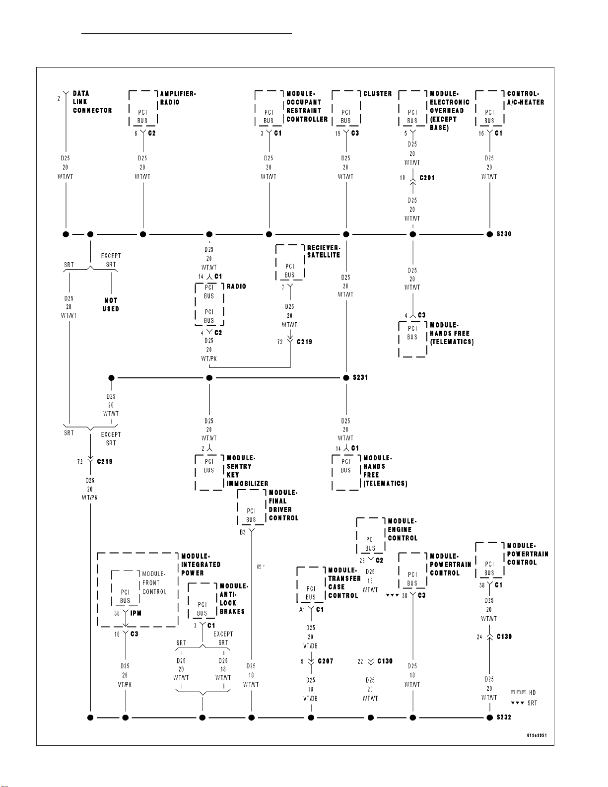
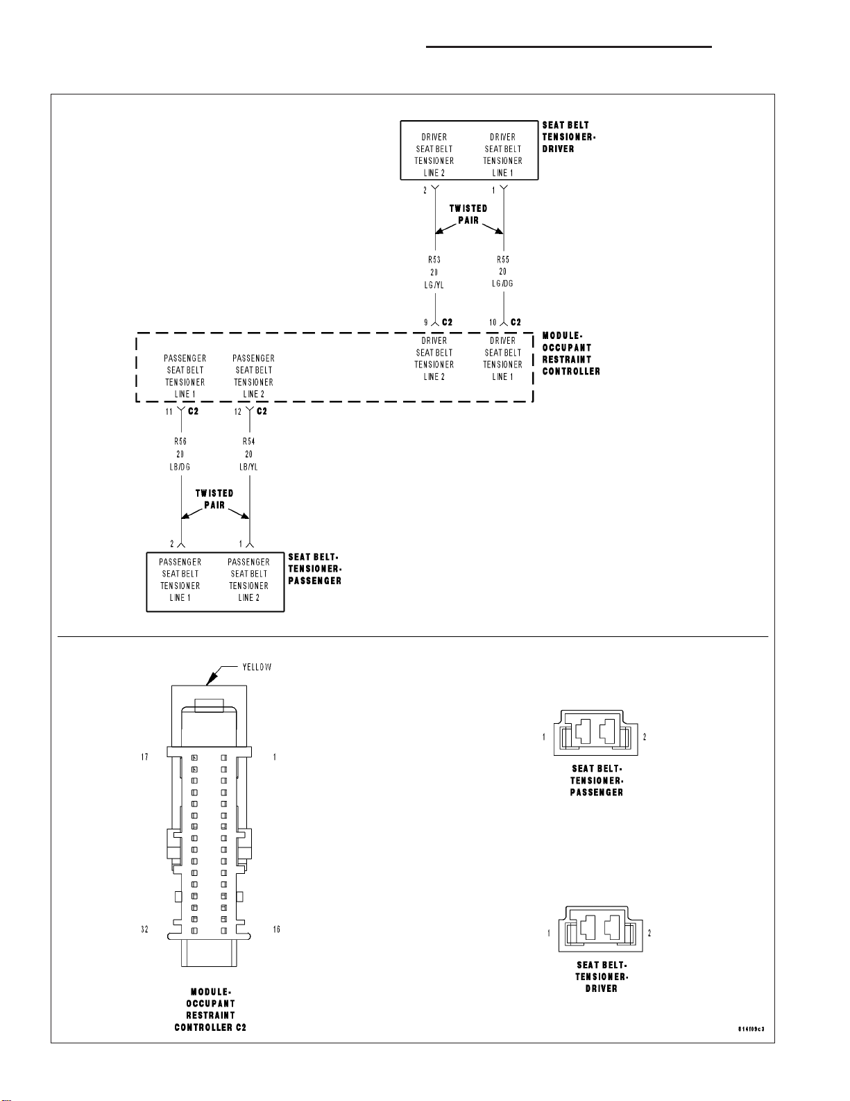
For the Air Bag System circuit diagram (Refer to 8 - ELECTRICAL/RESTRAINTS - SCHEMATICS AND DIAGRAMS).
For a complete wiring diagram Refer to Section 8W.
• When Monitored:
With the ignition on, the Occupant Restraint Controller (ORC) monitors the resistance of the Driver Seat Belt
Tensioner circuits.
• Set Condition:
The ORC has detected an open or high resistance on the Driver Seat Belt Tensioner circuits.
Possible Causes
(R55) DRIVER SEAT BELT TENSIONER LINE 1 CIRCUIT OR (R53) DRIVER SEAT BELT TENSIONER LINE 2
CIRCUIT OPEN
DRIVER SEAT BELT PRETENSIONER
ORC
Diagnostic Test
DETERMINE ACTIVE OR STORED DTC
1.
NOTE: Ensure the battery is fully charged.
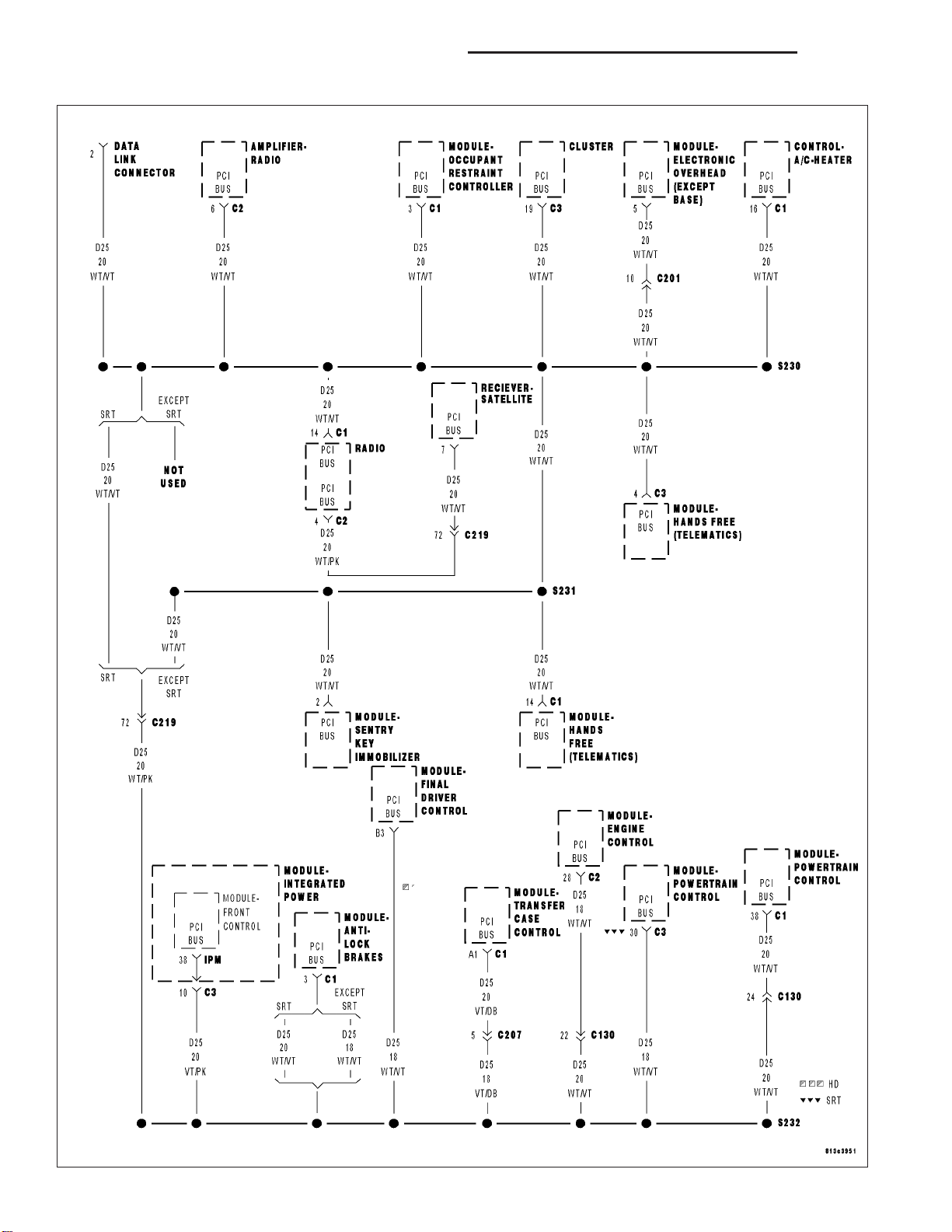
NOTE: The scan tool, SRS Airbag Load Tool MRL 8443, and DVOM are required to perform the following
test.
NOTE: When reconnecting airbag system components the Ignition must be turned off and the Battery must
be disconnected.
Select Active or Stored DTC.
Is the DTC active or stored?
ORC - ACTIVE DTC
Go To 2
ORC - STORED DTC
Go To 6
DR/DH RESTRAINTS - ELECTRICAL DIAGNOSTICS 8O - 17
DRIVER SEAT BELT TENSIONER CIRCUIT OPEN (CONTINUED)
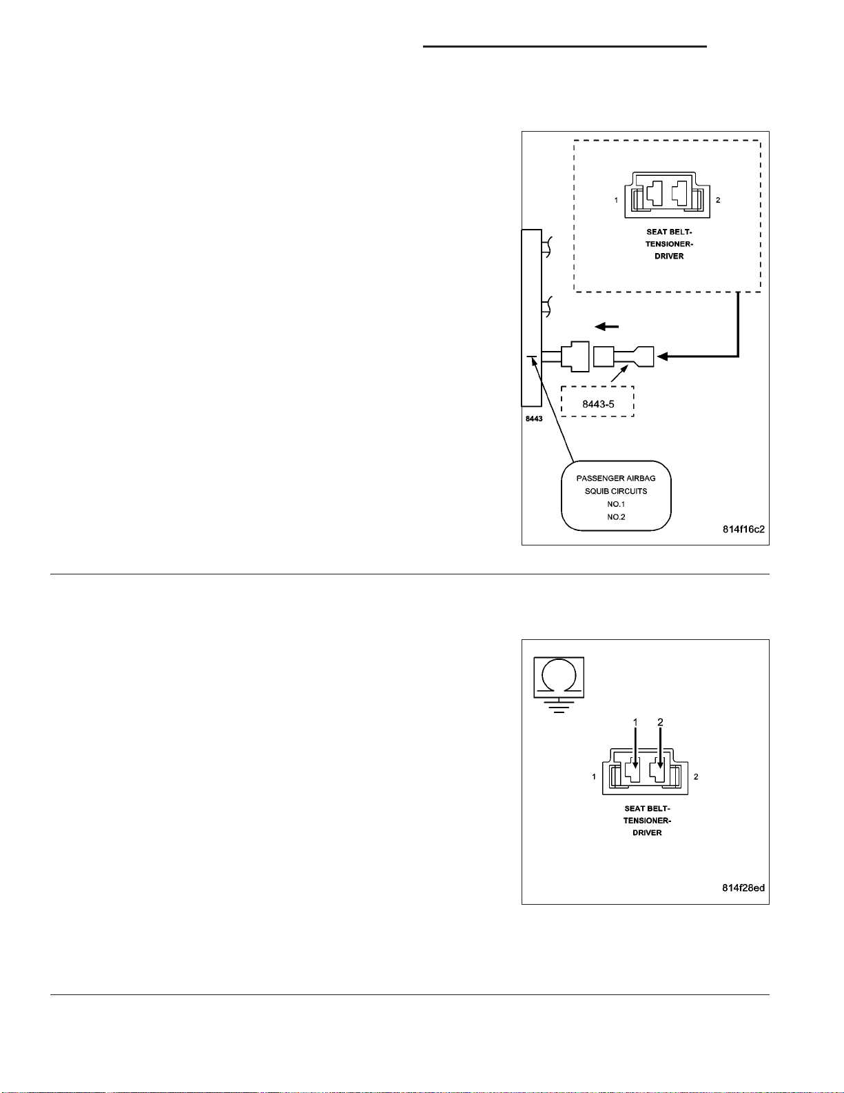
CHECK FOR OPEN DRIVER SEAT BELT PRETENSIONER
2.
WARNING: To avoid personal injury or death, turn the ignition off,
disconnect the battery and wait two minutes before proceeding.
Disconnect the Driver Seat Belt Pretensioner connector.
NOTE: Check connectors - Clean and repair as necessary.
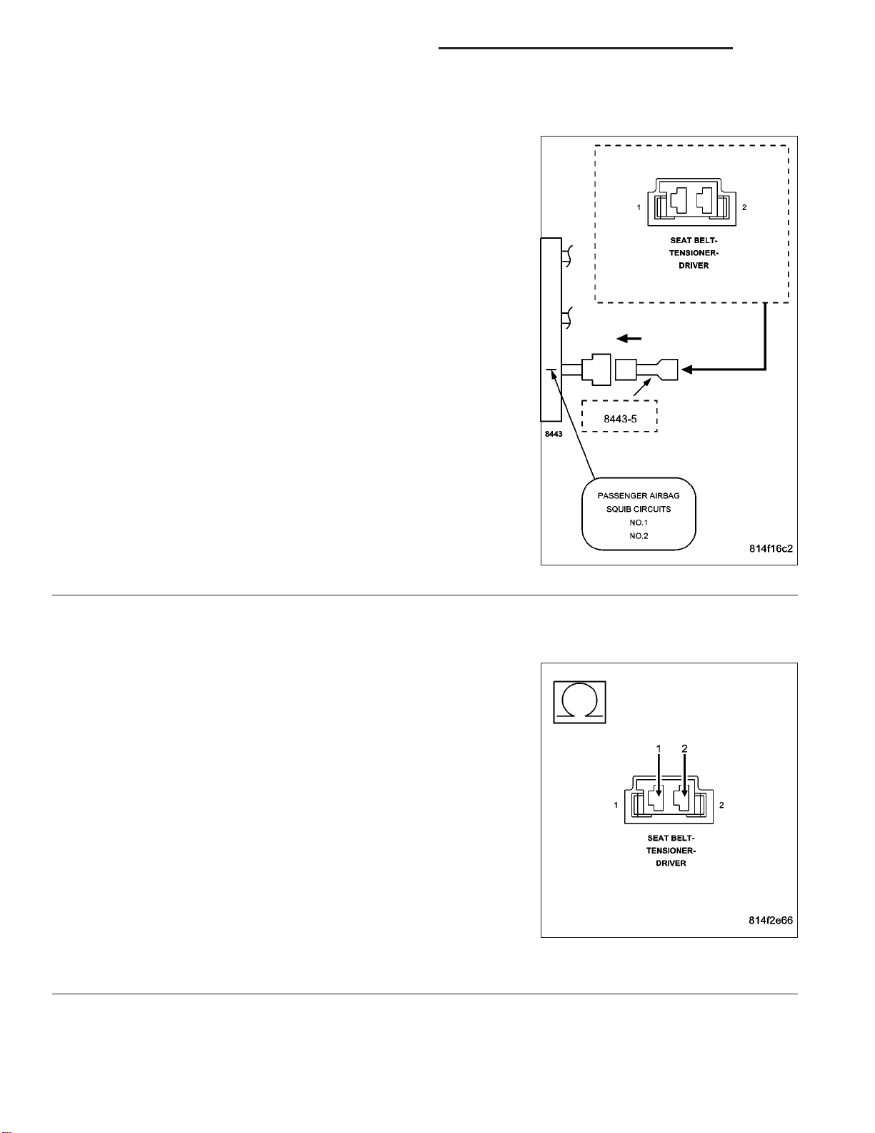
Connect the 8443 Load Tool and appropriate Jumper to the Driver
Seat Belt Pretensioner connector.
WARNING: To avoid personal injury or death, turn the ignition on,
then reconnect the battery.
With the scan tool, read the active ORC DTC’s.
Does the scan tool display: DRIVER SEAT BELT TENSIONER
CIRCUIT OPEN?
Yes >>
No >>
CHECK (R55) DRIVER SEAT BELT TENSIONER LINE 1
3.
CIRCUIT FOR AN OPEN
WARNING: To avoid personal injury or death, turn the ignition off,
disconnect the battery and wait two minutes before proceeding.
Disconnect the 8443 Load Tool and Jumper from the Driver Seat Belt
Pretensioner connector.
Disconnect the ORC connectors.
NOTE: Check connectors - Clean and repair as necessary.
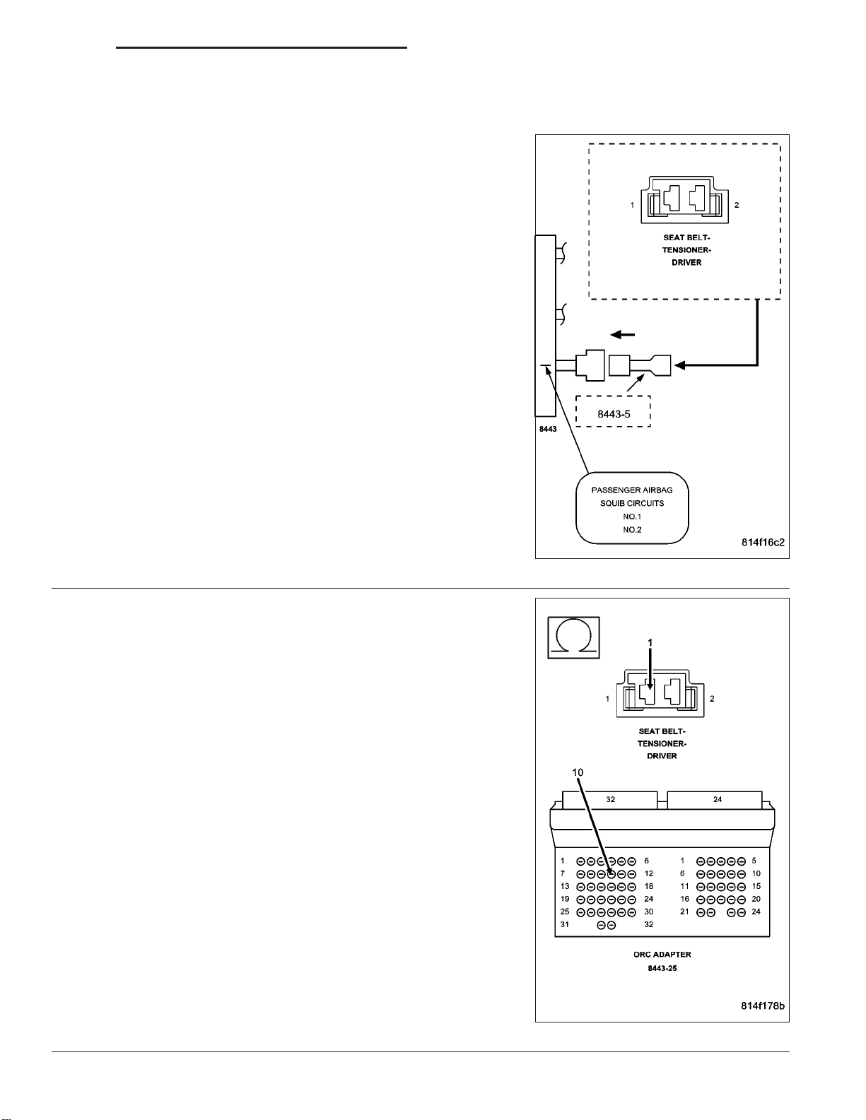
Connect the 8443 Load Tool ORC Adaptor to the ORC connector.
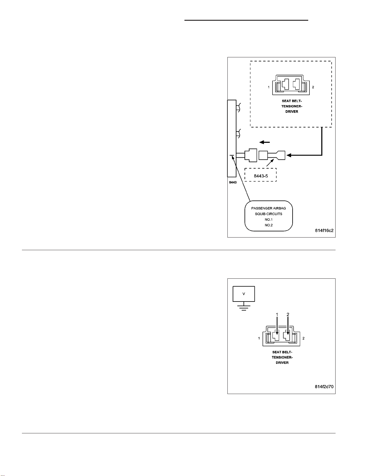
Measure the resistance of the (R55) Driver Seat Belt Tensioner Line 1
circuit between the Driver Seat Belt Pretensioner connector and the
8443 ORC Adaptor.
Go To 3
Replace the Driver Seat Belt Pretensioner in accordance
with the Service Information.
Perform ORC VERIFICATION TEST - VER 1
Is the resistance below 1.0 ohm?
Yes >>
No >>
Go To 4
Repair the (R55) Driver Seat Belt Tensioner Line 1 circuit
for and open. Then Go To 4
8O - 18 RESTRAINTS - ELECTRICAL DIAGNOSTICS DR/DH
DRIVER SEAT BELT TENSIONER CIRCUIT OPEN (CONTINUED)
CHECK (R53) DRIVER SEAT BELT TENSIONER LINE 2 CIRCUIT FOR AN OPEN
4.
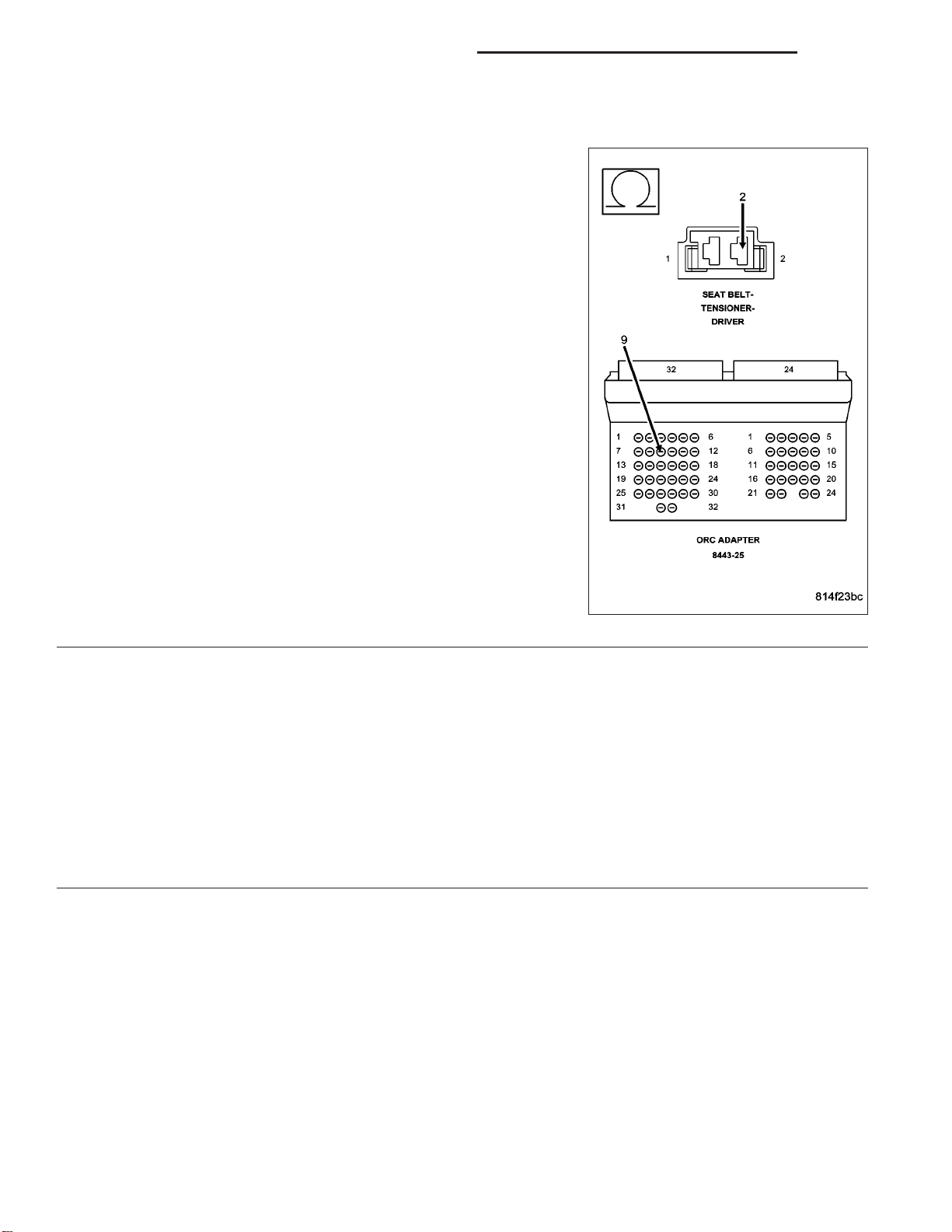
Measure the resistance of the (R53) Driver Seat Belt Tensioner Line 2
circuit between the Driver Seat Belt Pretensioner connector and the
8443 ORC Adaptor.
Is the resistance below 1.0 ohm?
Yes >>
No >>
REPLACE THE ORC
5.
WARNING: If the Occupant Restraint Controller (ORC) is dropped at any time, it must be replaced. Failure to
take the proper precautions can result in accidental airbag deployment and personal injury or death.
NOTE: When reconnecting airbag system components the Ignition must be turned off and the Battery must
be disconnected.
Go To 5
Repair the (R53) Driver Seat Belt Tensioner Line 2 circuit
for and open.
Perform ORC VERIFICATION TEST - VER 1
Repair
Replace the ORC in accordance with Service Information.
Perform ORC VERIFICATION TEST - VER 1

DR/DH RESTRAINTS - ELECTRICAL DIAGNOSTICS 8O - 19
DRIVER SEAT BELT TENSIONER CIRCUIT OPEN (CONTINUED)
STORED ORC DTC
6.
With the scan tool, record and erase all DTC’s from all Airbag System Modules.
If any ACTIVE codes are present they must be resolved before diagnosing any stored codes.
WARNING: TO AVOID PERSONAL INJURY OR DEATH, TURN THE IGNITION OFF, DISCONNECT THE BATTERY AND WAIT TWO MINUTES BEFORE PROCEEDING.
Using the wiring diagram/schematic as a guide, inspect the wiring and connectors.
Look for chaffed, pierced, pinched, or partially broken wires and broken, bent, pushed out, spread, corroded, or
contaminated terminals.
The following additional checks may assist you in identifying a possible intermittent problem.
Reconnect any disconnected components and harness connector.
WARNING: TO AVOID PERSONAL INJURY OR DEATH, TURN THE IGNITION ON, THEN RECONNECT THE
BATTERY.
With the scan tool monitor active codes as you work through the following steps.
Wiggle the wiring harness and connectors of the related airbag circuit or component.
If codes are related to the Driver Airbag circuits, rotate the steering wheel from stop to stop.
If only stored codes return continue the test until the problem area has been isolated.
In the previous steps you have attempted to recreate the conditions responsible for setting active DTC in question.
Are any ACTIVE DTCs present?
Yes >>
No >>
Select the appropriate diagnostic procedure from the Table of Contents in this section.
No problem found at this time. Erase all codes before returning vehicle to customer.
8O - 20 RESTRAINTS - ELECTRICAL DIAGNOSTICS DR/DH
DRIVER SEAT BELT TENSIONER CIRCUIT SHORT

DR/DH RESTRAINTS - ELECTRICAL DIAGNOSTICS 8O - 21
DRIVER SEAT BELT TENSIONER CIRCUIT SHORT (CONTINUED)
For the Air Bag System circuit diagram (Refer to 8 - ELECTRICAL/RESTRAINTS - SCHEMATICS AND DIAGRAMS).
For a complete wiring diagram Refer to Section 8W.
• When Monitored:
With the ignition on, the Occupant Restraint Controller (ORC) monitors the resistance of the Driver Seat Belt
Tensioner circuits.
• Set Condition:
The ORC has detected low resistance between the Driver Seat Belt Tensioner circuits.
Possible Causes
(R55) DRIVER SEAT BELT TENSIONER LINE 1 CIRCUIT SHORTED TO (R53) DRIVER SEAT BELT
TENSIONER LINE 2 CIRCUIT
DRIVER SEAT BELT PRETENSIONER
ORC
Diagnostic Test
SELECT ACTIVE OR STORED DTC
1.
NOTE: Ensure the battery is fully charged.
NOTE: The scan tool, SRS Airbag Load Tool MRL 8443, and DVOM are required to perform the following
test.
NOTE: When reconnecting airbag system components the Ignition must be turned off and the Battery must
be disconnected.
Select Active or Stored DTC.
Is the DTC active or stored?
ORC - ACTIVE DTC
Go To 2
ORC - STORED DTC
Go To 5
8O - 22 RESTRAINTS - ELECTRICAL DIAGNOSTICS DR/DH
DRIVER SEAT BELT TENSIONER CIRCUIT SHORT (CONTINUED)
CHECK FOR SHORTED DRIVER SEAT BELT PRETENSIONER
2.
WARNING: To avoid personal injury or death, turn the ignition off,
disconnect the battery and wait two minutes before proceeding.
Disconnect the Driver Seatbelt Pretensioner connector.
NOTE: Check connectors - Clean and repair as necessary.
Connect the 8443 Load Tool and appropriate Jumper to the Driver
Seat Belt Pretensioner connector.
WARNING: To avoid personal injury or death, turn the ignition on
then reconnect the battery.
With the scan tool, read the active ORC DTC’s.
Does the scan tool display: DRIVER SEAT BELT TENSIONER
CIRCUIT SHORT?
Yes >>
No >>
CHECK (R55) DRIVER SEAT BELT TENSIONER LINE 1 CIRCUIT FOR A SHORT TO (R53) DRIVER SEAT
3.
BELT TENSIONER LINE 2 CIRCUIT
WARNING: To avoid personal injury or death, turn the ignition off,
disconnect the battery and wait two minutes before proceeding.
Disconnect the 8443 Load Tool and Jumper from the Driver Seat Belt
Pretensioner connector.
Disconnect the ORC connectors.
NOTE: Check connectors - Clean and repair as necessary.
Connect the 8443 Load Tool ORC Adaptor to the ORC connector.
Measure the resistance between the (R55) Driver Seat Belt Tensioner
Line 1 circuit and the (R53) Driver Seat Belt Tensioner Line 2 circuit at
the Driver Seat Belt Pretensioner connector.
Go To 3
Replace the Driver Seat Belt Pretensioner in accordance
with the Service Information.
Perform ORC VERIFICATION TEST - VER 1
Is the resistance below 10K ohms?
Yes >>
No >>
Repair the (R55) Driver Seat Belt Tensioner Line 1 circuit
for a short to the (R53) Driver Seat Belt Tensioner Line 2
circuit.
Perform ORC VERIFICATION TEST - VER 1
Go To 4

DR/DH RESTRAINTS - ELECTRICAL DIAGNOSTICS 8O - 23
DRIVER SEAT BELT TENSIONER CIRCUIT SHORT (CONTINUED)
REPLACE THE ORC
4.
WARNING: If the Occupant Restraint Controller (ORC) is dropped at any time, it must be replaced. Failure to
take the proper precautions can result in accidental airbag deployment and personal injury or death.
NOTE: When reconnecting airbag system components the Ignition must be turned off and the Battery must
be disconnected.
Repair
Replace the ORC in accordance with the Service Information.
Perform ORC VERIFICATION TEST - VER 1
STORED ORC DTC
5.
With the scan tool, record and erase all DTC’s from all Airbag System Modules.
If any ACTIVE codes are present they must be resolved before diagnosing any stored codes.
WARNING: To avoid personal injury or death, turn the ignition off, disconnect the battery and wait two minutes before proceeding.
Using the wiring diagram/schematic as a guide, inspect the wiring and connectors.
Look for chaffed, pierced, pinched, or partially broken wires and broken, bent, pushed out, spread, corroded, or
contaminated terminals.
The following additional checks may assist you in identifying a possible intermittent problem.
Reconnect any disconnected components and harness connector.
WARNING: To avoid personal injury or death, turn the ignition on, then reconnect the battery.
With the scan tool monitor active codes as you work through the following steps.
Wiggle the wiring harness and connectors of the related airbag circuit or component.
If codes are related to the Driver Airbag circuits, rotate the steering wheel from stop to stop.
If only stored codes return continue the test until the problem area has been isolated.
In the previous steps you have attempted to recreate the conditions responsible for setting active DTC in question.
Are any ACTIVE DTC’s present?
Yes >>
No >>
Select the appropriate diagnostic procedure from the Table of Contents in this section.
No problem found at this time. Erase all codes before returning vehicle to customer.

8O - 24 RESTRAINTS - ELECTRICAL DIAGNOSTICS DR/DH
DRIVER SEAT BELT TENSIONER SHORT TO BATTERY

DR/DH RESTRAINTS - ELECTRICAL DIAGNOSTICS 8O - 25
DRIVER SEAT BELT TENSIONER SHORT TO BATTERY (CONTINUED)
For the Air Bag System circuit diagram (Refer to 8 - ELECTRICAL/RESTRAINTS - SCHEMATICS AND DIAGRAMS).
For a complete wiring diagram Refer to Section 8W.
• When Monitored:
With the ignition on, the Occupant Restraint Controller (ORC) monitors the voltage on the Driver Seat Belt
Tensioner circuits.
• Set Condition:
The ORC detects voltage on the Driver Seat Belt Tensioner circuits.
Possible Causes
(R55) DRIVER SEAT BELT TENSIONER LINE 1 CIRCUIT OR (R53) DRIVER SEAT BELT TENSIONER LINE 2
CIRCUIT SHORTED TO BATTERY
DRIVER SEAT BELT PRETENSIONER
ORC
Diagnostic Test
DETERMINE ACTIVE OR STORED DTC
1.
NOTE: Ensure the battery is fully charged.
NOTE: The scan tool, SRS Airbag Load Tool MRL 8443, and DVOM are required to perform the following
test.
NOTE: When reconnecting airbag system components the Ignition must be turned off and the Battery must
be disconnected.
Select Active or Stored DTC.
Is the DTC active or stored?
ORC - ACTIVE DTC
Go To 2
ORC - STORED DTC
Go To 5
8O - 26 RESTRAINTS - ELECTRICAL DIAGNOSTICS DR/DH
DRIVER SEAT BELT TENSIONER SHORT TO BATTERY (CONTINUED)
CHECK FOR SHORTED DRIVER SEAT BELT PRETENSIONER
2.
WARNING: To avoid personal injury or death, turn the ignition off,
disconnect the battery and wait two minutes before proceeding.
Disconnect the Driver Seat Belt Pretensioner connector.
NOTE: Check connectors - Clean and repair as necessary.
Connect the 8443 Load Tool and appropriate Jumper to the Driver
Seat Belt Pretensioner connector.
WARNING: To avoid personal injury or death, turn the ignition on,
then reconnect the battery.
With the scan tool, read the active ORC DTC’s.
Does the scan tool display: DRIVER SEAT BELT TENSIONER
SHORT TO BATTERY?
Yes >>
No >>
CHECK (R55) DRIVER SEAT BELT TENSIONER LINE 1 CIRCUIT AND (R53) DRIVER SEAT BELT
3.
TENSIONER LINE 2 CIRCUIT FOR A SHORT TO BATTERY
WARNING: To avoid personal injury or death, turn the ignition off,
disconnect the battery and wait two minutes before proceeding.
Disconnect the 8443 Load Tool and Jumper from the Driver Seat Belt
Pretensioner connector.
Disconnect the ORC connectors.
NOTE: Check connectors - Clean and repair as necessary.
Connect the 8443 Load Tool ORC Adaptor to the ORC connector.
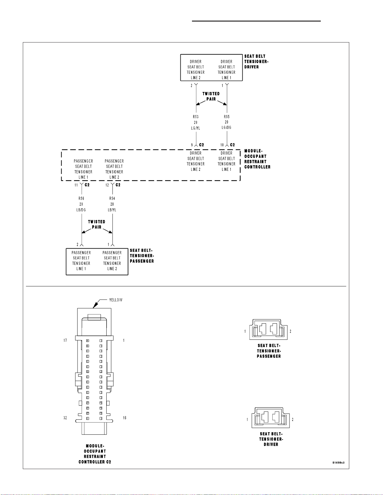
Measure the voltage of the (R55) Driver Seat Belt Tensioner Line 1
circuit between the Driver Seat Belt Pretensioner connector and
ground.
Measure the voltage of the (R53) Driver Seat Belt Tensioner Line 2
circuit between the Driver Seat Belt Pretensioner connector and
ground.
Go To 3
Replace the Driver Seat Belt Pretensioner in accordance
with the Service Information.
Perform ORC VERIFICATION TEST - VER 1
Is there any voltage present on either circuit?
Yes >>
No >>
Repair the Driver Seat Belt Tensioner circuits with voltage
present for a short to battery.
Perform ORC VERIFICATION TEST - VER 1
Go To 4

DR/DH RESTRAINTS - ELECTRICAL DIAGNOSTICS 8O - 27
DRIVER SEAT BELT TENSIONER SHORT TO BATTERY (CONTINUED)
REPLACE THE ORC
4.
WARNING: To avoid personal injury or death, turn the ignition off, disconnect the battery and wait two minutes before proceeding.
WARNING: If the Occupant Restraint Controller (ORC) is dropped at any time, it must be replaced. Failure to
take the proper precautions can result in accidental airbag deployment and personal injury or death.
NOTE: When reconnecting airbag system components the Ignition must be turned off and the Battery must
be disconnected.
Repair
Replace the ORC in accordance with the Service Information.
Perform ORC VERIFICATION TEST - VER 1
STORED ORC DTC
5.
With the scan tool, record and erase all DTC’s from all Airbag System Modules.
If any ACTIVE codes are present they must be resolved before diagnosing any stored codes.
WARNING: To avoid personal injury or death, turn the ignition off, disconnect the battery and wait two minutes before proceeding.
Using the wiring diagram/schematic as a guide, inspect the wiring and connectors.
Look for chaffed, pierced, pinched, or partially broken wires and broken, bent, pushed out, spread, corroded, or
contaminated terminals.
The following additional checks may assist you in identifying a possible intermittent problem.
Reconnect any disconnected components and harness connector.
WARNING: To avoid personal injury or death, turn the ignition on, then reconnect the battery.
With the scan tool monitor active codes as you work through the following steps.
Wiggle the wiring harness and connectors of the related airbag circuit or component.
If codes are related to the Driver Airbag circuits, rotate the steering wheel from stop to stop.
If only stored codes return continue the test until the problem area has been isolated.
In the previous steps you have attempted to recreate the conditions responsible for setting active DTC in question.
Are any ACTIVE DTCs present?
Yes >>
No >>
Select the appropriate diagnostic procedure from the Table of Contents in this section.
No problem found at this time. Erase all codes before returning vehicle to customer.
8O - 28 RESTRAINTS - ELECTRICAL DIAGNOSTICS DR/DH
DRIVER SEAT BELT TENSIONER SHORT TO GROUND

DR/DH RESTRAINTS - ELECTRICAL DIAGNOSTICS 8O - 29
DRIVER SEAT BELT TENSIONER SHORT TO GROUND (CONTINUED)
For the Air Bag System circuit diagram (Refer to 8 - ELECTRICAL/RESTRAINTS - SCHEMATICS AND DIAGRAMS).
For a complete wiring diagram Refer to Section 8W.
• When Monitored:
With the ignition on, the Occupant Restraint Controller (ORC) monitors the resistance of the Driver Seat Belt
Tensioner circuits.
• Set Condition:
The ORC has detected low resistance on the Driver Seat Belt Tensioner circuits.
Possible Causes
(R55) DRIVER SEAT BELT TENSIONER LINE 1 CIRCUIT OR (R53) DRIVER SEAT BELT TENSIONER LINE 2
CIRCUIT SHORTED TO GROUND
DRIVER SEAT BELT PRETENSIONER
ORC
Diagnostic Test
DETERMINE ACTIVE OR STORED DTC
1.
NOTE: Ensure the battery is fully charged.
NOTE: The scan tool, SRS Airbag Load Tool MRL 8443, and DVOM are required to perform the following
test.
NOTE: When reconnecting airbag system components the Ignition must be turned off and the Battery must
be disconnected.
Select Active or Stored DTC.
Is the DTC active or stored?
ORC - ACTIVE DTC
Go To 2
ORC - STORED DTC
Go To 5
8O - 30 RESTRAINTS - ELECTRICAL DIAGNOSTICS DR/DH
DRIVER SEAT BELT TENSIONER SHORT TO GROUND (CONTINUED)
CHECK FOR SHORTED DRIVER SEAT BELT PRETENSIONER
2.
WARNING: To avoid personal injury or death, turn the ignition off,
disconnect the battery and wait two minutes before proceeding.
Disconnect the Driver Seat Belt Pretensioner connector.
NOTE: Check connectors - Clean and repair as necessary.
Connect the 8443 Load Tool and appropriate Jumper to the Driver
Seat Belt Pretensioner connector.
WARNING: To avoid personal injury or death, turn the ignition on,
then reconnect the battery.
With the scan tool, read the active ORC DTC’s.
Does the scan tool display: DRIVER SEAT BELT TENSIONER
SHORT TO GROUND?
Yes >>
No >>
CHECK (R55) DRIVER SEAT BELT TENSIONER LINE 1 CIRCUIT AND (R53) DRIVER SEAT BELT
3.
TENSIONER LINE 2 CIRCUIT FOR A SHORT TO GROUND
WARNING: To avoid personal injury or death, turn the ignition off,
disconnect the battery and wait two minutes before proceeding.
Disconnect the 8443 Load Tool and Jumper from the Driver Seat Belt
Pretensioner connector.
Disconnect the ORC connectors.
NOTE: Check connectors - Clean and repair as necessary.
Connect the 8443 Load Tool ORC Adaptor to the ORC connector.
Measure the resistance of the (R55) Driver Seat Belt Tensioner Line 1
circuit between ground and the Driver Seat Belt Pretensioner connector.
Measure the resistance of the (R53) Driver Seat Belt Tensioner Line 2
circuit between ground and the Driver Seat Belt Pretensioner connector.
Go To 3
Replace the Driver Seat Belt Pretensioner in accordance
with the Service Information.
Perform ORC VERIFICATION TEST - VER 1
Is the resistance below 10K ohms on either circuit?
Yes >>
No >>
Repair the Driver Seat Belt Tensioner circuits with a resistance below 10K ohms for a short to ground.
Perform ORC VERIFICATION TEST - VER 1
Go To 4

DR/DH RESTRAINTS - ELECTRICAL DIAGNOSTICS 8O - 31
DRIVER SEAT BELT TENSIONER SHORT TO GROUND (CONTINUED)
REPLACE THE ORC
4.
WARNING: If the Occupant Restraint Controller (ORC) is dropped at any time, it must be replaced. Failure to
take the proper precautions can result in accidental airbag deployment and personal injury or death.
NOTE: When reconnecting airbag system components the Ignition must be turned off and the Battery must
be disconnected.
Repair
Replace the ORC in accordance with the Service Information.
Perform ORC VERIFICATION TEST - VER 1
STORED ORC DTC
5.
With the scan tool, record and erase all DTC’s from all Airbag System Modules.
If any ACTIVE codes are present they must be resolved before diagnosing any stored codes.
WARNING: To avoid personal injury or death, turn the ignition off, disconnect the battery and wait two minutes before proceeding.
Using the wiring diagram/schematic as a guide, inspect the wiring and connectors.
Look for chaffed, pierced, pinched, or partially broken wires and broken, bent, pushed out, spread, corroded, or
contaminated terminals.
The following additional checks may assist you in identifying a possible intermittent problem.
Reconnect any disconnected components and harness connector.
WARNING: To avoid personal injury or death, turn the ignition on, then reconnect the battery.
With the scan tool monitor active codes as you work through the following steps.
Wiggle the wiring harness and connectors of the related airbag circuit or component.
If codes are related to the Driver Airbag circuits, rotate the steering wheel from stop to stop.
If only stored codes return continue the test until the problem area has been isolated.
In the previous steps you have attempted to recreate the conditions responsible for setting active DTC in question.
Are any ACTIVE DTC’s present?
Yes >>
No >>
Select the appropriate diagnostic procedure from the Table of Contents in this section.
No problem found at this time. Erase all codes before returning vehicle to customer.

8O - 32 RESTRAINTS - ELECTRICAL DIAGNOSTICS DR/DH
DRIVER SQUIB 1 CIRCUIT OPEN

DR/DH RESTRAINTS - ELECTRICAL DIAGNOSTICS 8O - 33
DRIVER SQUIB 1 CIRCUIT OPEN (CONTINUED)
For the Air Bag System circuit diagram (Refer to 8 - ELECTRICAL/RESTRAINTS - SCHEMATICS AND DIAGRAMS).
For a complete wiring diagram Refer to Section 8W.
• When Monitored:
With the ignition on, the Occupant Restraint Controller (ORC) monitors the resistance of the Driver Squib 1
circuits.
• Set Condition:
The ORC has detected an open or high resistance on the Driver Squib 1 circuits.
Possible Causes
DRIVER SQUIB 1 LINE 2 CIRCUIT OPEN
DRIVER SQUIB 1 LINE 1 CIRCUIT OPEN
CLOCKSPRING
DRIVER AIRBAG
ORC
Diagnostic Test
DETERMINE ACTIVE OR STORED DTC
1.
NOTE: Ensure the battery is fully charged.
NOTE: The scan tool, SRS Airbag Load Tool MRL 8443, and DVOM are required to perform the following
test.
NOTE: When reconnecting airbag system components the Ignition must be turned off and the Battery must
be disconnected.
Select Active or Stored DTC.
Is the DTC active or stored?
ORC - ACTIVE DTC
Go To 2
ORC - STORED DTC
Go To 7

8O - 34 RESTRAINTS - ELECTRICAL DIAGNOSTICS DR/DH
DRIVER SQUIB 1 CIRCUIT OPEN (CONTINUED)
CHECK FOR OPEN SQUIB CIRCUITS IN DRIVER AIRBAG
2.
WARNING: To avoid personal injury or death, turn the ignition off,
disconnect the battery and wait two minutes before proceeding.
Disconnect the Driver Airbag Squib connectors.
WARNING: To avoid personal injury or death, do not place an
intact undeployed airbag face down on a hard surface, the airbag
will propel into the air if accidentally deployed.
NOTE: Check connectors - Clean and repair as necessary.
Connect the 8443 Load Tool and appropriate Jumper to the Driver Airbag Squib connectors.
WARNING: To avoid personal injury or death, turn the ignition on,
then reconnect the battery.
With the scan tool, read the active ORC DTC’s.
Does the scan tool display: DRIVER SQUIB 1 CIRCUIT OPEN?
Yes >>
No >>
CHECK CLOCKSPRING SQUIB CIRCUITS FOR AN OPEN
3.
WARNING: To avoid personal injury or death, turn the ignition off,
disconnect the battery and wait two minutes before proceeding.
Disconnect the 8443 Load Tool and Jumper from the Driver Airbag
Squib connectors.
Disconnect the Clockspring connector.
NOTE: Check connectors - Clean and repair as necessary.
Connect the 8443 Load Tool and appropriate Jumper to the Clockspring connector.
WARNING: To avoid personal injury or death, turn the ignition on,
then reconnect the battery.
With the scan tool, read the active ORC DTC’s.
Go To 3
Replace the Driver Airbag in accordance with the Service
Information.
Perform ORC VERIFICATION TEST - VER 1
Does the scan tool display: DRIVER SQUIB 1 CIRCUIT OPEN?
Yes >>
No >>
Go To 4
Replace the Clockspring in accordance with the Service
Information.
Perform ORC VERIFICATION TEST - VER 1

DR/DH RESTRAINTS - ELECTRICAL DIAGNOSTICS 8O - 35
DRIVER SQUIB 1 CIRCUIT OPEN (CONTINUED)
CHECK DRIVER SQUIB 1 LINE 2 CIRCUIT FOR AN OPEN
4.
WARNING: To avoid personal injury or death, turn the ignition off,
disconnect the battery and wait two minutes before proceeding.
Disconnect the 8443 Load Tool and Jumper from the Clockspring connector.
Disconnect the ORC connectors.
NOTE: Check connectors - Clean and repair as necessary.
Connect the 8443 Load Tool ORC Adaptor to the ORC connector.
Measure the resistance of the Driver Squib 1 Line 2 circuit between
the Clockspring connector and the ORC Load Tool Adaptor.
Is the resistance below 1.0 ohm?
Yes >>
No >>
CHECK DRIVER SQUIB 1 LINE 1 CIRCUIT FOR AN OPEN
5.
Measure the resistance of the Driver Squib 1 Line 1 circuit between
the Clockspring connector and the ORC Load Tool Adaptor.
Is the resistance below 1.0 ohm?
Yes >>
No >>
Go To 5
Repair the Driver Squib 1 Line 2 circuit for an open. Then,
Go To 5
Go To 6
Repair the Driver Squib 1 Line 1 circuit for an open.
Perform ORC VERIFICATION TEST - VER 1

8O - 36 RESTRAINTS - ELECTRICAL DIAGNOSTICS DR/DH
DRIVER SQUIB 1 CIRCUIT OPEN (CONTINUED)
REPLACE THE ORC
6.
WARNING: If the Occupant Restraint Controller (ORC) is dropped at any time, it must be replaced. Failure to
take the proper precautions can result in accidental airbag deployment and personal injury or death.
NOTE: When reconnecting airbag system components the Ignition must be turned off and the Battery must
be disconnected.
Repair
Replace the ORC in accordance with the Service Information.
Perform ORC VERIFICATION TEST - VER 1
STORED ORC DTC
7.
With the scan tool, record and erase all DTC’s from all Airbag System Modules.
If any ACTIVE codes are present they must be resolved before diagnosing any stored codes.
WARNING: To avoid personal injury or death, turn the ignition off, disconnect the battery and wait two minutes before proceeding.
Using the wiring diagram/schematic as a guide, inspect the wiring and connectors.
Look for chaffed, pierced, pinched, or partially broken wires and broken, bent, pushed out, spread, corroded, or
contaminated terminals.
The following additional checks may assist you in identifying a possible intermittent problem.
Reconnect any disconnected components and harness connector.
WARNING: To avoid personal injury or death, turn the ignition on, then reconnect the battery.
With the scan tool monitor active codes as you work through the following steps.
Wiggle the wiring harness and connectors of the related airbag circuit or component.
If codes are related to the Driver Airbag circuits, rotate the steering wheel from stop to stop.
If only stored codes return continue the test until the problem area has been isolated.
In the previous steps you have attempted to recreate the conditions responsible for setting active DTC in question.
Are any ACTIVE DTC’s present?
Yes >>
No >>
Select the appropriate diagnostic procedure from the Table of Contents in this section.
No problem found at this time. Erase all codes before returning vehicle to customer.

DR/DH RESTRAINTS - ELECTRICAL DIAGNOSTICS 8O - 37
DRIVER SQUIB 1 CIRCUIT SHORT

8O - 38 RESTRAINTS - ELECTRICAL DIAGNOSTICS DR/DH
DRIVER SQUIB 1 CIRCUIT SHORT (CONTINUED)
For the Air Bag System circuit diagram (Refer to 8 - ELECTRICAL/RESTRAINTS - SCHEMATICS AND DIAGRAMS).
For a complete wiring diagram Refer to Section 8W.
• When Monitored:
With the ignition on, the Occupant Restraint Controller (ORC) monitors the resistance of the Driver Squib 1
circuits.
• Set Condition:
The ORC has detected low resistance between the Driver Squib 1 circuits.
Possible Causes
DRIVER SQUIB 1 LINE 2 CIRCUIT SHORTED TO DRIVER SQUIB 1 LINE 1 CIRCUIT
CLOCKSPRING
DRIVER AIRBAG
ORC
Diagnostic Test
DETERMINE ACTIVE OR STORED DTC
1.
NOTE: Ensure the battery is fully charged.
NOTE: The scan tool, SRS Airbag Load Tool MRL 8443, and DVOM are required to perform the following
test.
NOTE: When reconnecting airbag system components the Ignition must be turned off and the Battery must
be disconnected.
Select Active or Stored DTC.
Is the DTC active or stored?
ORC - ACTIVE DTC
Go To 2
ORC - STORED DTC
Go To 6

DR/DH RESTRAINTS - ELECTRICAL DIAGNOSTICS 8O - 39
DRIVER SQUIB 1 CIRCUIT SHORT (CONTINUED)
CHECK FOR SHORTED SQUIB CIRCUITS IN DRIVER AIRBAG
2.
WARNING: To avoid personal injury or death, turn the ignition off,
disconnect the battery and wait two minutes before proceeding.
WARNING: To avoid personal injury or death, do not place an
intact undeployed airbag face down on a hard surface, the airbag
will propel into the air if accidentally deployed.
Disconnect the Driver Airbag Squib connectors.
NOTE: Check connectors - Clean and repair as necessary.
Connect the 8443 Load Tool and appropriate Jumper to the Driver Airbag Squib connectors.
WARNING: To avoid personal injury or death, turn the ignition on,
then reconnect the battery.
With the scan tool, read the active ORC DTC’s.
Does the scan tool display: DRIVER SQUIB 1 CIRCUIT SHORT?
Yes >>
No >>
Go To 3
Replace the Driver Airbag in accordance with the Service
Information.
Perform ORC VERIFICATION TEST - VER 1
CHECK CLOCKSPRING SQUIB CIRCUITS FOR A SHORT
3.
TOGETHER
WARNING: To avoid personal injury or death, turn the ignition off,
disconnect the battery and wait two minutes before proceeding.
Disconnect the 8443 Load Tool ORC from the Driver Airbag Squib
connectors.
Disconnect the Clockspring connector.
NOTE: Check connectors - Clean and repair as necessary.
Connect the 8443 Load Tool and appropriate Jumper to the Clockspring connector.
WARNING: To avoid personal injury or death, turn the ignition on,
then reconnect the battery.
With the scan tool, read the active ORC DTC’s.
Does the scan tool display: DRIVER SQUIB 1 CIRCUIT SHORT?
Yes >>
No >>
Go To 4
Replace the Clockspring in accordance with the Service
Information.
Perform ORC VERIFICATION TEST - VER 1

8O - 40 RESTRAINTS - ELECTRICAL DIAGNOSTICS DR/DH
DRIVER SQUIB 1 CIRCUIT SHORT (CONTINUED)
CHECK DRIVER SQUIB 1 LINE 2 CIRCUIT FOR A SHORT TO DRIVER SQUIB 1 LINE 1 CIRCUIT
4.
WARNING: To avoid personal injury or death, turn the ignition off,
disconnect the battery and wait two minutes before proceeding.
Disconnect the 8443 Load Tool and Jumper from the Clockspring connector.
Disconnect the ORC connectors.
NOTE: Check connectors - Clean and repair as necessary.
Connect the 8443 Load Tool ORC Adaptor to the ORC connector.
Measure the resistance between the Driver Squib 1 Line 2 circuit and
the Driver Squib 1 Line 1 circuit at the Clockspring connector.
Is the resistance below 10K ohms?
Yes >>
No >>
REPLACE THE ORC
5.
WARNING: If the Occupant Restraint Controller (ORC) is dropped at any time, it must be replaced. Failure to
take the proper precautions can result in accidental airbag deployment and personal injury or death.
NOTE: When reconnecting airbag system components the Ignition must be turned off and the Battery must
be disconnected.
Repair
Repair the Driver Squib 1 Line 2 circuit for a short to the
Driver Squib 1 Line 1 circuit.
Perform ORC VERIFICATION TEST - VER 1
Go To 5
Replace the ORC in accordance with the Service Information.
Perform ORC VERIFICATION TEST - VER 1

DR/DH RESTRAINTS - ELECTRICAL DIAGNOSTICS 8O - 41
DRIVER SQUIB 1 CIRCUIT SHORT (CONTINUED)
STORED ORC DTC
6.
With the scan tool, record and erase all DTC’s from all Airbag System Modules.
If any ACTIVE codes are present they must be resolved before diagnosing any stored codes.
WARNING: To avoid personal injury or death, turn the ignition off, disconnect the battery and wait two minutes before proceeding.
Using the wiring diagram/schematic as a guide, inspect the wiring and connectors.
Look for chaffed, pierced, pinched, or partially broken wires and broken, bent, pushed out, spread, corroded, or
contaminated terminals.
The following additional checks may assist you in identifying a possible intermittent problem.
Reconnect any disconnected components and harness connector.
WARNING: To avoid personal injury or death, turn the ignition on, then reconnect the battery.
With the scan tool monitor active codes as you work through the following steps.
Wiggle the wiring harness and connectors of the related airbag circuit or component.
If codes are related to the Driver Airbag circuits, rotate the steering wheel from stop to stop.
If only stored codes return continue the test until the problem area has been isolated.
In the previous steps you have attempted to recreate the conditions responsible for setting active DTC in question.
Are any ACTIVE DTCs present?
Yes >>
No >>
Select the appropriate diagnostic procedure from the Table of Contents in this section.
No problem found at this time. Erase all codes before returning vehicle to customer.

8O - 42 RESTRAINTS - ELECTRICAL DIAGNOSTICS DR/DH
DRIVER SQUIB 1 SHORT TO BATTERY

DR/DH RESTRAINTS - ELECTRICAL DIAGNOSTICS 8O - 43
DRIVER SQUIB 1 SHORT TO BATTERY (CONTINUED)
For the Air Bag System circuit diagram (Refer to 8 - ELECTRICAL/RESTRAINTS - SCHEMATICS AND DIAGRAMS).
For a complete wiring diagram Refer to Section 8W.
• When Monitored:
With the ignition on, the Occupant Restraint Controller (ORC) monitors the voltage on the Driver Squib 1 circuits.
• Set Condition:
The ORC has detected voltage on the Driver Squib 1 circuits.
Possible Causes
DRIVER SQUIB 1 LINE 2 CIRCUIT OR DRIVER SQUIB 1 LINE 1 CIRCUIT SHORTED TO BATTERY
CLOCKSPRING
DRIVER AIRBAG
ORC
Diagnostic Test
DETERMINE ACTIVE OR STORED DTC
1.
NOTE: Ensure the battery is fully charged.
NOTE: The scan tool, SRS Airbag Load Tool MRL 8443, and DVOM are required to perform the following
test.
NOTE: When reconnecting airbag system components the Ignition must be turned off and the Battery must
be disconnected.
Select Active or Stored DTC.
Is the DTC active or stored?
ORC - ACTIVE DTC
Go To 2
ORC - STORED DTC
Go To 6

8O - 44 RESTRAINTS - ELECTRICAL DIAGNOSTICS DR/DH
DRIVER SQUIB 1 SHORT TO BATTERY (CONTINUED)
CHECK FOR SHORTED SQUIB CIRCUITS IN DRIVER AIRBAG
2.
WARNING: To avoid personal injury or death, turn the ignition off,
disconnect the battery and wait two minutes before proceeding.
Disconnect the Driver Airbag Squib connectors.
WARNING: To avoid personal injury or death, do not place an
intact undeployed airbag face down on a hard surface, the airbag
will propel into the air if accidentally deployed.
NOTE: Check connectors - Clean and repair as necessary.
Connect the 8443 Load Tool and appropriate Jumper to the Driver Airbag Squib connectors.
WARNING: To avoid personal injury or death, turn the ignition on,
then reconnect the battery.
With the scan tool, read the active ORC DTC’s.
Does the scan tool display: DRIVER SQUIB 1 SHORT TO BATTERY?
Yes >>
No >>
CHECK CLOCKSPRING SQUIB CIRCUITS FOR A SHORT TO
3.
BATTERY
WARNING: To avoid personal injury or death, turn the ignition off,
disconnect the battery and wait two minutes before proceeding.
Disconnect the 8443 Load Tool and Jumper from the Driver Airbag
Squib connectors.
Disconnect the Clockspring connector.
NOTE: Check connectors - Clean and repair as necessary.
Connect the 8443 Load Tool and appropriate Jumper to the Clockspring connector.
WARNING: To avoid personal injury or death, turn the ignition on,
then reconnect the battery.
With the scan tool, read the active ORC DTC’s.
Go To 3
Replace the Driver Airbag in accordance with the Service
Information.
Perform ORC VERIFICATION TEST - VER 1
Does the scan tool display: DRIVER SQUIB 1 SHORT TO BATTERY?
Yes >>
No >>
Go To 4
Replace the Clockspring in accordance with the Service
Information.
Perform ORC VERIFICATION TEST - VER 1

DR/DH RESTRAINTS - ELECTRICAL DIAGNOSTICS 8O - 45
DRIVER SQUIB 1 SHORT TO BATTERY (CONTINUED)
CHECK DRIVER SQUIB 1 LINE 2 CIRCUIT AND DRIVER SQUIB 1 LINE 1 CIRCUIT FOR A SHORT TO
4.
BATTERY
WARNING: To avoid personal injury or death, turn the ignition off,
disconnect the battery and wait two minutes before proceeding.
Disconnect the 8443 Load Tool and Jumper from the Clockspring connector.
Disconnect the ORC connectors.
NOTE: Check connectors - Clean and repair as necessary.
Connect the 8443 Load Tool ORC Adaptor to the ORC connector.
WARNING: To avoid personal injury or death, turn the ignition on,
then reconnect the battery.
Measure the voltage of the Driver Squib 1 Line 2 circuit between the
Clockspring connector and ground.
Measure the voltage of the Driver Squib 1 Line 1 circuit between the
Clockspring connector and ground.
Is there any voltage present for either measurement?
Yes >>
No >>
REPLACE THE ORC
5.
WARNING: To avoid personal injury or death, turn the ignition off, disconnect the battery and wait two minutes before proceeding.
WARNING: If the Occupant Restraint Controller (ORC) is dropped at any time, it must be replaced. Failure to
take the proper precautions can result in accidental airbag deployment and personal injury or death.
NOTE: When reconnecting airbag system components the Ignition must be turned off and the Battery must
be disconnected.
Repair
Repair the Driver Squib 1 circuits with voltage present for
a short to Battery.
Perform ORC VERIFICATION TEST - VER 1
Go To 5
Replace the ORC in accordance with the Service Information.
Perform ORC VERIFICATION TEST - VER 1

8O - 46 RESTRAINTS - ELECTRICAL DIAGNOSTICS DR/DH
DRIVER SQUIB 1 SHORT TO BATTERY (CONTINUED)
STORED ORC DTC
6.
With the scan tool, record and erase all DTC’s from all Airbag System Modules.
If any ACTIVE codes are present they must be resolved before diagnosing any stored codes.
WARNING: To avoid personal injury or death, turn the ignition off, disconnect the battery and wait two minutes before proceeding.
Using the wiring diagram/schematic as a guide, inspect the wiring and connectors.
Look for chaffed, pierced, pinched, or partially broken wires and broken, bent, pushed out, spread, corroded, or
contaminated terminals.
The following additional checks may assist you in identifying a possible intermittent problem.
Reconnect any disconnected components and harness connector.
WARNING: To avoid personal injury or death, turn the ignition on, then reconnect the battery.
With the scan tool monitor active codes as you work through the following steps.
Wiggle the wiring harness and connectors of the related airbag circuit or component.
If codes are related to the Driver Airbag circuits, rotate the steering wheel from stop to stop.
If only stored codes return continue the test until the problem area has been isolated.
In the previous steps you have attempted to recreate the conditions responsible for setting active DTC’s in question.
Are any ACTIVE DTC’s present?
Yes >>
No >>
Select the appropriate diagnostic procedure from the Table of Contents in this section.
No problem found at this time. Erase all codes before returning vehicle to customer.

DR/DH RESTRAINTS - ELECTRICAL DIAGNOSTICS 8O - 47
DRIVER SQUIB 1 SHORT TO GROUND

8O - 48 RESTRAINTS - ELECTRICAL DIAGNOSTICS DR/DH
DRIVER SQUIB 1 SHORT TO GROUND (CONTINUED)
For the Air Bag System circuit diagram (Refer to 8 - ELECTRICAL/RESTRAINTS - SCHEMATICS AND DIAGRAMS).
For a complete wiring diagram Refer to Section 8W.
• When Monitored:
With the ignition on, the Occupant Restraint Controller (ORC) monitors the resistance of the Driver Squib 1
circuits.
• Set Condition:
The ORC has detected low resistance on the Driver Squib 1 circuits.
Possible Causes
DRIVER SQUIB 1 LINE 2 CIRCUIT OR DRIVER SQUIB 1 LINE 1 CIRCUIT SHORTED TO GROUND
CLOCKSPRING
DRIVER AIRBAG
ORC
Diagnostic Test
DETERMINE ACTIVE OR STORED DTC
1.
NOTE: Ensure the battery is fully charged.
NOTE: The scan tool, SRS Airbag Load Tool MRL 8443, and DVOM are required to perform the following
test.
NOTE: When reconnecting airbag system components the Ignition must be turned off and the Battery must
be disconnected.
Select Active or Stored DTC.
Is the DTC active or stored?
ORC - ACTIVE DTC
Go To 2
ORC - STORED DTC
Go To 6

DR/DH RESTRAINTS - ELECTRICAL DIAGNOSTICS 8O - 49
DRIVER SQUIB 1 SHORT TO GROUND (CONTINUED)
CHECK FOR SHORTED SQUIB CIRCUITS IN DRIVER AIRBAG
2.
WARNING: To avoid personal injury or death, turn the ignition off,
disconnect the battery and wait two minutes before proceeding.
Disconnect the Driver Airbag Squib connectors.
WARNING: To avoid personal injury or death, do not place an
intact undeployed airbag face down on a hard surface, the airbag
will propel into the air if accidentally deployed.
NOTE: Check connectors - Clean and repair as necessary.
Connect the 8443 Load Tool and appropriate Jumper to the Driver Airbag Squib connectors.
WARNING: To avoid personal injury or death, turn the ignition on,
then reconnect the battery.
With the scan tool, read the active ORC DTC’s.
Does the scan tool display: DRIVER SQUIB 1 SHORT TO
GROUND?
Yes >>
No >>
CHECK CLOCKSPRING SQUIB CIRCUITS FOR A SHORT TO
3.
GROUND
WARNING: To avoid personal injury or death, turn the ignition off,
disconnect the battery and wait two minutes before proceeding.
Disconnect the 8443 Load Tool Jumper from the Driver Airbag Squib
connectors.
Disconnect the Clockspring connector.
NOTE: Check connectors - Clean and repair as necessary.
Connect the 8443 Load Tool and appropriate Jumper to the Clockspring connector.
WARNING: To avoid personal injury or death, turn the ignition on,
then reconnect the battery.
With the scan tool, read the active ORC DTC’s.
Go To 3
Replace the Driver Airbag in accordance with the Service
Information.
Perform ORC VERIFICATION TEST - VER 1
Does the scan tool display: DRIVER SQUIB 1 SHORT TO
GROUND?
Yes >>
No >>
Go To 4
Replace the Clockspring in accordance with the Service
Information.
Perform ORC VERIFICATION TEST - VER 1

8O - 50 RESTRAINTS - ELECTRICAL DIAGNOSTICS DR/DH
DRIVER SQUIB 1 SHORT TO GROUND (CONTINUED)
CHECK DRIVER SQUIB 1 LINE 2 CIRCUIT AND DRIVER SQUIB 1 LINE 1 CIRCUIT FOR A SHORT TO
4.
GROUND
WARNING: To avoid personal injury or death, turn the ignition off,
disconnect the battery and wait two minutes before proceeding.
Disconnect the 8443 Load Tool and Jumper from the Clockspring connector.
Disconnect the ORC connectors.
NOTE: Check connectors - Clean and repair as necessary.
Connect the 8443 Load Tool ORC Adaptor to the ORC connector.
Measure the resistance of the Driver Squib 1 Line 2 circuit between
ground and the Clockspring connector.
Measure the resistance of the Driver Squib 1 Line 1 circuit between
ground and the Clockspring connector.
Is the resistance below 10K ohms for either measurement?
Yes >>
No >>
REPLACE THE ORC
5.
WARNING: If the Occupant Restraint Controller (ORC) is dropped at any time, it must be replaced. Failure to
take the proper precautions can result in accidental airbag deployment and personal injury or death.
NOTE: When reconnecting airbag system components the Ignition must be turned off and the Battery must
be disconnected.
Repair
Repair the Driver Squib 1 circuits with a resistance below
10K ohms for a short to ground.
Perform ORC VERIFICATION TEST - VER 1
Go To 5
Replace the ORC in accordance with the Service Information.
Perform ORC VERIFICATION TEST - VER 1

DR/DH RESTRAINTS - ELECTRICAL DIAGNOSTICS 8O - 51
DRIVER SQUIB 1 SHORT TO GROUND (CONTINUED)
STORED ORC DTC
6.
With the scan tool, record and erase all DTC’s from all Airbag System Modules.
If any ACTIVE codes are present they must be resolved before diagnosing any stored codes.
WARNING: To avoid personal injury or death, turn the ignition off, disconnect the battery and wait two minutes before proceeding.
Using the wiring diagram/schematic as a guide, inspect the wiring and connectors.
Look for chaffed, pierced, pinched, or partially broken wires and broken, bent, pushed out, spread, corroded, or
contaminated terminals.
The following additional checks may assist you in identifying a possible intermittent problem.
Reconnect any disconnected components and harness connector.
WARNING: To avoid personal injury or death, turn the ignition on, then reconnect the battery.
With the scan tool monitor active codes as you work through the following steps.
Wiggle the wiring harness and connectors of the related airbag circuit or component.
If codes are related to the Driver Airbag circuits, rotate the steering wheel from stop to stop.
If only stored codes return continue the test until the problem area has been isolated.
In the previous steps you have attempted to recreate the conditions responsible for setting active DTC in question.
Are any ACTIVE DTCs present?
Yes >>
No >>
Select the appropriate diagnostic procedure from the Table of Contents in this section.
No problem found at this time. Erase all codes before returning vehicle to customer.

8O - 52 RESTRAINTS - ELECTRICAL DIAGNOSTICS DR/DH
DRIVER SQUIB 2 CIRCUIT OPEN

DR/DH RESTRAINTS - ELECTRICAL DIAGNOSTICS 8O - 53
DRIVER SQUIB 2 CIRCUIT OPEN (CONTINUED)
For the Air Bag System circuit diagram (Refer to 8 - ELECTRICAL/RESTRAINTS - SCHEMATICS AND DIAGRAMS).
For a complete wiring diagram Refer to Section 8W.
• When Monitored:
With the ignition on, the Occupant Restraint Controller (ORC) monitors the resistance of the Driver Squib 2
circuits.
• Set Condition:
The ORC has detected an open or high resistance on the Driver Squib 2 circuits.
Possible Causes
DRIVER SQUIB 2 LINE 1 CIRCUIT OPEN
DRIVER SQUIB 2 LINE 2 CIRCUIT OPEN
CLOCKSPRING
DRIVER AIRBAG
ORC
Diagnostic Test
DETERMINE ACTIVE OR STORED DTC
1.
NOTE: Ensure the battery is fully charged.
NOTE: The scan tool, SRS Airbag Load Tool MRL 8443, and DVOM are required to perform the following
test.
NOTE: When reconnecting airbag system components the Ignition must be turned off and the Battery must
be disconnected.
Select Active or Stored DTC.
Is the DTC active or stored?
ORC - ACTIVE DTC
Go To 2
ORC - STORED DTC
Go To 7

8O - 54 RESTRAINTS - ELECTRICAL DIAGNOSTICS DR/DH
DRIVER SQUIB 2 CIRCUIT OPEN (CONTINUED)
CHECK FOR OPEN SQUIB CIRCUITS IN DRIVER AIRBAG
2.
WARNING: To avoid personal injury or death, turn the ignition off,
disconnect the battery and wait two minutes before proceeding.
Disconnect the Driver Airbag Squib connectors.
WARNING: To avoid personal injury or death, do not place an
intact undeployed airbag face down on a hard surface, the airbag
will propel into the air if accidentally deployed.
NOTE: Check connectors - Clean and repair as necessary.
Connect the 8443 Load Tool and appropriate Jumper to the Driver Airbag Squib connectors.
WARNING: To avoid personal injury or death, turn the ignition on,
then reconnect the battery.
With the scan tool, read the active ORC DTC’s.
Does the scan tool display: DRIVER SQUIB 2 CIRCUIT OPEN?
Yes >>
No >>
CHECK CLOCKSPRING SQUIB CIRCUITS FOR AN OPEN
3.
WARNING: To avoid personal injury or death, turn the ignition off,
disconnect the battery and wait two minutes before proceeding.
Disconnect the 8443 Load Tool and Jumper from the Driver Airbag
Squib connectors.
Disconnect the Clockspring connector.
NOTE: Check connectors - Clean and repair as necessary.
Connect the 8443 Load Tool and appropriate Jumper to the Clockspring connector.
WARNING: To avoid personal injury or death, turn the ignition on,
then reconnect the battery.
With the scan tool, read the active ORC DTC’s.
Go To 3
Replace the Driver Airbag in accordance with the Service
Information.
Perform ORC VERIFICATION TEST - VER 1
Does the scan tool display: DRIVER SQUIB 2 CIRCUIT OPEN?
Yes >>
No >>
Go To 4
Replace the Clockspring in accordance with the Service
Information.
Perform ORC VERIFICATION TEST - VER 1

DR/DH RESTRAINTS - ELECTRICAL DIAGNOSTICS 8O - 55
DRIVER SQUIB 2 CIRCUIT OPEN (CONTINUED)
CHECK DRIVER SQUIB 2 LINE 1 CIRCUIT FOR AN OPEN
4.
WARNING: To avoid personal injury or death, turn the ignition off,
disconnect the battery and wait two minutes before proceeding.
Disconnect the 8443 Load Tool and Jumper from the Clockspring connector.
Disconnect the ORC connectors.
NOTE: Check connectors - Clean and repair as necessary.
Connect the 8443 Load Tool ORC Adaptor to the ORC connector.
Measure the resistance of the Driver Squib 2 Line 1 circuit between
the Clockspring connector and the ORC Load Tool Adaptor.
Is the resistance below 1.0 ohm?
Yes >>
No >>
CHECK DRIVER SQUIB 2 LINE 2 CIRCUIT FOR AN OPEN
5.
Measure the resistance of the Driver Squib 2 Line 2 circuit between
the Clockspring connector and the ORC Load Tool Adaptor.
Is the resistance below 1.0 ohm?
Yes >>
No >>
Go To 5
Repair the Driver Squib 2 Line 1 circuit for an open. Then,
Go To 5
Perform ORC VERIFICATION TEST - VER 1
Go To 6
Repair the Driver Squib 2 Line 2 circuit for an open.
Perform ORC VERIFICATION TEST - VER 1

8O - 56 RESTRAINTS - ELECTRICAL DIAGNOSTICS DR/DH
DRIVER SQUIB 2 CIRCUIT OPEN (CONTINUED)
REPLACE THE ORC
6.
WARNING: If the Occupant Restraint Controller (ORC) is dropped at any time, it must be replaced. Failure to
take the proper precautions can result in accidental airbag deployment and personal injury or death.
NOTE: When reconnecting airbag system components the Ignition must be turned off and the Battery must
be disconnected.
Repair
Replace the ORC in accordance with the Service Information.
Perform ORC VERIFICATION TEST - VER 1
STORED ORC DTC
7.
With the scan tool, record and erase all DTC’s from all Airbag System Modules.
If any ACTIVE codes are present they must be resolved before diagnosing any stored codes.
WARNING: To avoid personal injury or death, turn the ignition off, disconnect the battery and wait two minutes before proceeding.
Using the wiring diagram/schematic as a guide, inspect the wiring and connectors.
Look for chaffed, pierced, pinched, or partially broken wires and broken, bent, pushed out, spread, corroded, or
contaminated terminals.
The following additional checks may assist you in identifying a possible intermittent problem.
Reconnect any disconnected components and harness connector.
WARNING: To avoid personal injury or death, turn the ignition on, then reconnect the battery.
With the scan tool monitor active codes as you work through the following steps.
Wiggle the wiring harness and connectors of the related airbag circuit or component.
If codes are related to the Driver Airbag circuits, rotate the steering wheel from stop to stop.
If only stored codes return continue the test until the problem area has been isolated.
In the previous steps you have attempted to recreate the conditions responsible for setting active DTC in question.
Are any ACTIVE DTC’s present?
Yes >>
No >>
Select the appropriate diagnostic procedure from the Table of Contents in this section.
No problem found at this time. Erase all codes before returning vehicle to customer.
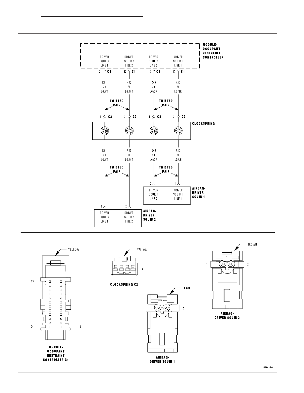
DR/DH RESTRAINTS - ELECTRICAL DIAGNOSTICS 8O - 57
DRIVER SQUIB 2 CIRCUIT SHORT

8O - 58 RESTRAINTS - ELECTRICAL DIAGNOSTICS DR/DH
DRIVER SQUIB 2 CIRCUIT SHORT (CONTINUED)
For the Air Bag System circuit diagram (Refer to 8 - ELECTRICAL/RESTRAINTS - SCHEMATICS AND DIAGRAMS).
For a complete wiring diagram Refer to Section 8W.
• When Monitored:
With the ignition on, the Occupant Restraint Controller (ORC) monitors the resistance of the Driver Squib 2
circuits.
• Set Condition:
The ORC has detected low resistance between the Driver Squib 2 circuits.
Possible Causes
DRIVER SQUIB 2 LINE 1 CIRCUIT SHORTED TO DRIVER SQUIB 2 LINE 2 CIRCUIT
CLOCKSPRING
DRIVER AIRBAG
ORC
Diagnostic Test
DETERMINE ACTIVE OR STORED DTC
1.
NOTE: Ensure the battery is fully charged.
NOTE: The Scan Tool, SRS Airbag Load Tool MRL 8443 and DVOM are required to perform the following
test.
NOTE: When reconnecting airbag system components the Ignition must be turned off and the Battery must
be disconnected.
Select Active or Stored DTC.
Is the DTC active or stored?
ORC - ACTIVE DTC
Go To 2
ORC - STORED DTC
Go To 6

DR/DH RESTRAINTS - ELECTRICAL DIAGNOSTICS 8O - 59
DRIVER SQUIB 2 CIRCUIT SHORT (CONTINUED)
CHECK FOR SHORTED SQUIB CIRCUITS IN DRIVER AIRBAG
2.
WARNING: To avoid personal injury or death, turn the ignition off,
disconnect the battery and wait two minutes before proceeding.
WARNING: To avoid personal injury or death, do not place an
intact undeployed airbag face down on a hard surface, the airbag
will propel into the air if accidentally deployed.
Disconnect the Driver Airbag Squib connectors.
NOTE: Check connectors - Clean and repair as necessary.
Connect the 8443 Load Tool and appropriate Jumper to the Driver Airbag Squib connectors.
WARNING: To avoid personal injury or death, turn the ignition on,
then reconnect the battery.
With the scan tool, read the active ORC DTC’s.
Does the scan tool display: DRIVER SQUIB 2 CIRCUIT SHORT?
Yes >>
No >>
Go To 3
Replace the Driver Airbag in accordance with the Service
Information.
Perform ORC VERIFICATION TEST - VER 1
CHECK CLOCKSPRING SQUIB CIRCUITS FOR A SHORT
3.
TOGETHER
WARNING: To avoid personal injury or death, turn the ignition off,
disconnect the battery and wait two minutes before proceeding.
Disconnect the 8443 Load Tool ORC from the Driver Airbag Squib
connectors.
Disconnect the Clockspring connector.
NOTE: Check connectors - Clean and repair as necessary.
Connect the 8443 Load Tool and appropriate Jumper to the Clockspring connector.
WARNING: To avoid personal injury or death, turn the ignition on,
then reconnect the battery.
With the scan tool, read the active ORC DTC’s.
Does the scan tool display: DRIVER SQUIB 2 CIRCUIT SHORT?
Yes >>
No >>
Go To 4
Replace the Clockspring in accordance with the Service
Information.
Perform ORC VERIFICATION TEST - VER 1
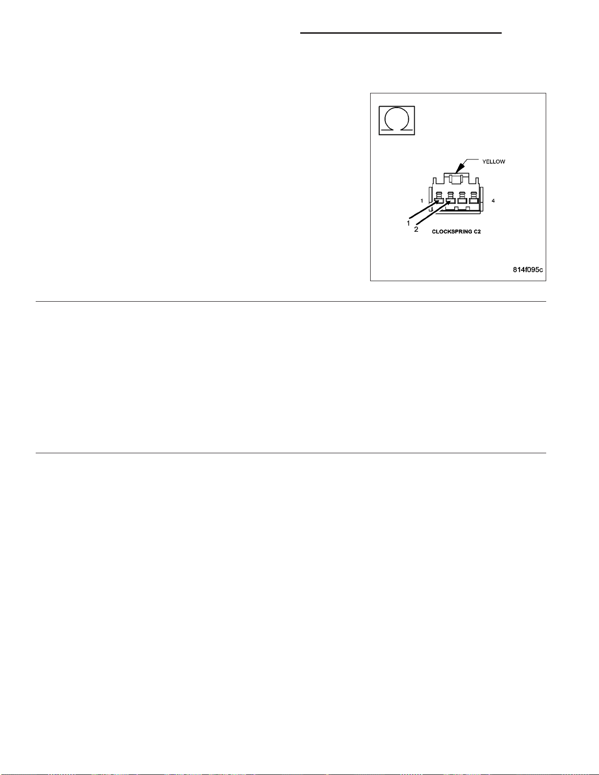
8O - 60 RESTRAINTS - ELECTRICAL DIAGNOSTICS DR/DH
DRIVER SQUIB 2 CIRCUIT SHORT (CONTINUED)
CHECK DRIVER SQUIB 2 LINE 1 CIRCUIT FOR A SHORT TO DRIVER SQUIB 2 LINE 2 CIRCUIT
4.
WARNING: To avoid personal injury or death, turn the ignition off,
disconnect the battery and wait two minutes before proceeding.
Disconnect the 8443 Load Tool and Jumper from the Clockspring connector.
Disconnect the ORC connectors.
NOTE: Check connectors - Clean and repair as necessary.
Connect the 8443 Load Tool ORC Adaptor to the ORC connector.
Measure the resistance between the Driver Squib 2 Line 1 circuit and
the Driver Squib 2 Line 2 circuit at the Clockspring connector.
Is the resistance below 10K ohms?
Yes >>
No >>
REPLACE THE ORC
5.
WARNING: If the Occupant Restraint Controller (ORC) is dropped at any time, it must be replaced. Failure to
take the proper precautions can result in accidental airbag deployment and personal injury or death.
NOTE: When reconnecting airbag system components the Ignition must be turned off and the Battery must
be disconnected.
Repair
Repair the Driver Squib 2 Line 1 circuit for a short to the
Driver Squib 2 Line 2 circuit.
Perform ORC VERIFICATION TEST - VER 1
Go To 5
Replace the ORC in accordance with the Service Information.
Perform ORC VERIFICATION TEST - VER 1

DR/DH RESTRAINTS - ELECTRICAL DIAGNOSTICS 8O - 61
DRIVER SQUIB 2 CIRCUIT SHORT (CONTINUED)
STORED ORC DTC
6.
With the scan tool, record and erase all DTC’s from all Airbag System Modules.
If any ACTIVE codes are present they must be resolved before diagnosing any stored codes.
WARNING: To avoid personal injury or death, turn the ignition off, disconnect the battery and wait two minutes before proceeding.
Using the wiring diagram/schematic as a guide, inspect the wiring and connectors.
Look for chaffed, pierced, pinched, or partially broken wires and broken, bent, pushed out, spread, corroded, or
contaminated terminals.
The following additional checks may assist you in identifying a possible intermittent problem.
Reconnect any disconnected components and harness connector.
WARNING: To avoid personal injury or death, turn the ignition on, then reconnect the battery.
With the scan tool monitor active codes as you work through the following steps.
Wiggle the wiring harness and connectors of the related airbag circuit or component.
If codes are related to the Driver Airbag circuits, rotate the steering wheel from stop to stop.
If only stored codes return continue the test until the problem area has been isolated.
In the previous steps you have attempted to recreate the conditions responsible for setting active DTC in question.
Are any ACTIVE DTCs present?
Yes >>
No >>
Select the appropriate diagnostic procedure from the Table of Contents in this section.
No problem found at this time. Erase all codes before returning vehicle to customer.
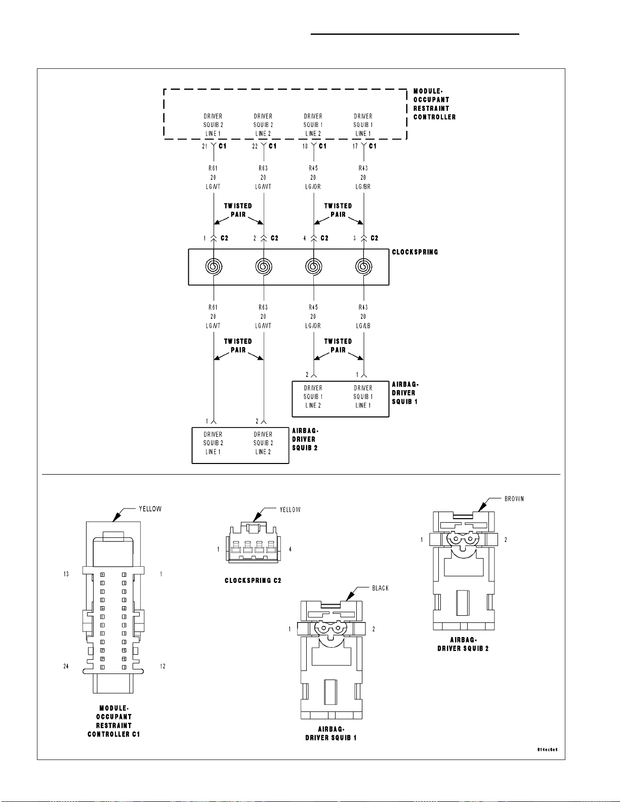
8O - 62 RESTRAINTS - ELECTRICAL DIAGNOSTICS DR/DH
DRIVER SQUIB 2 SHORT TO BATTERY

DR/DH RESTRAINTS - ELECTRICAL DIAGNOSTICS 8O - 63
DRIVER SQUIB 2 SHORT TO BATTERY (CONTINUED)
For the Air Bag System circuit diagram (Refer to 8 - ELECTRICAL/RESTRAINTS - SCHEMATICS AND DIAGRAMS).
For a complete wiring diagram Refer to Section 8W.
• When Monitored:
With the ignition on, the Occupant Restraint Controller (ORC) monitors the voltage on the Driver Squib 2 circuits.
• Set Condition:
The ORC has detected voltage on the Driver Squib 2 circuits.
Possible Causes
DRIVER SQUIB 2 LINE 1 CIRCUIT OR DRIVER SQUIB 2 LINE 2 CIRCUIT SHORTED TO BATTERY
CLOCKSPRING
DRIVER AIRBAG
ORC
Diagnostic Test
DETERMINE ACTIVE OR STORED DTC
1.
NOTE: Ensure the battery is fully charged.
NOTE: The Scan Tool, SRS Airbag Load Tool MRL 8443 and DVOM are required to perform the following
test.
NOTE: When reconnecting airbag system components the Ignition must be turned off and the Battery must
be disconnected.
Select Active or Stored DTC.
Is the DTC active or stored?
ORC - ACTIVE DTC
Go To 2
ORC - STORED DTC
Go To 6
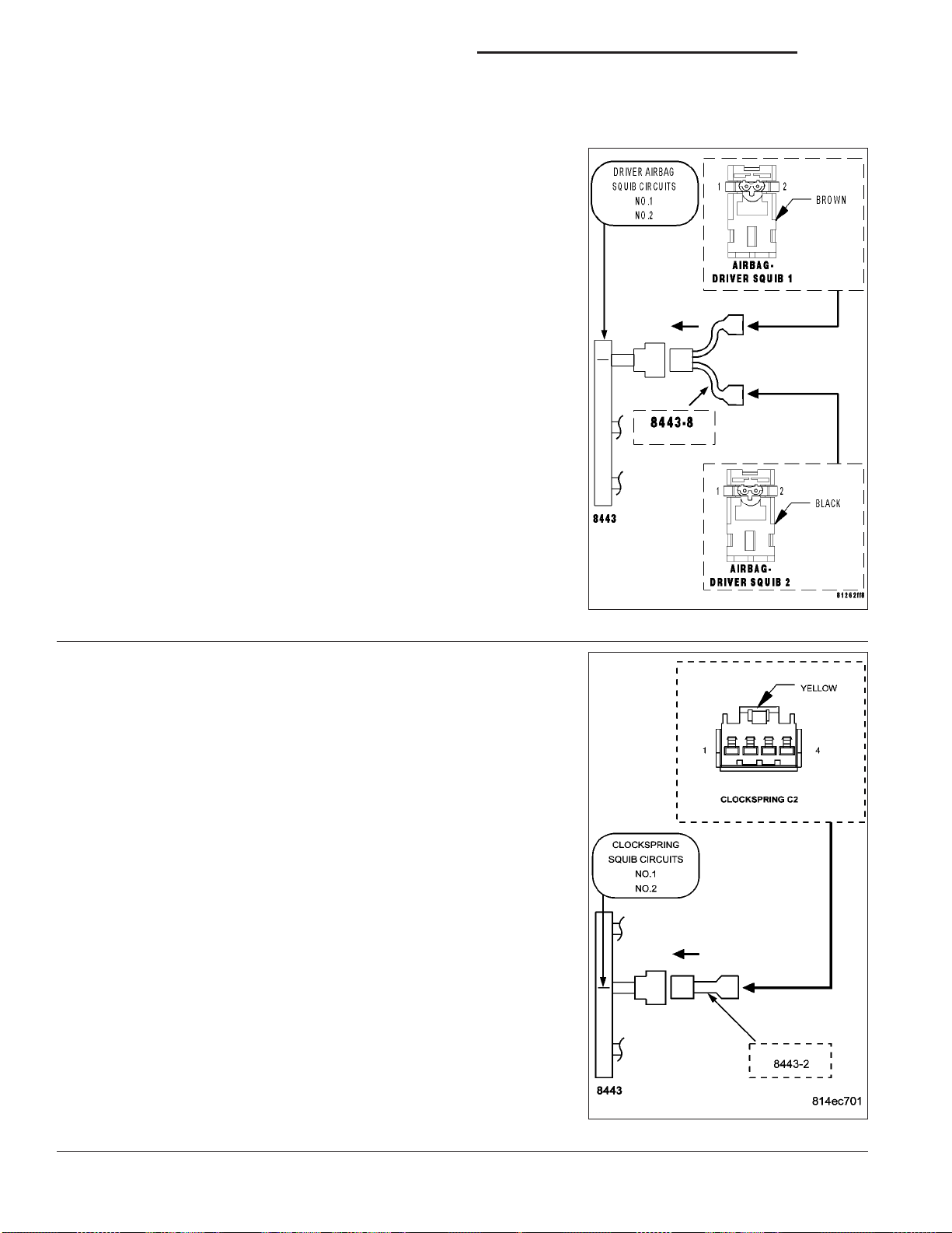
8O - 64 RESTRAINTS - ELECTRICAL DIAGNOSTICS DR/DH
DRIVER SQUIB 2 SHORT TO BATTERY (CONTINUED)
CHECK FOR SHORTED SQUIB CIRCUITS IN DRIVER AIRBAG
2.
WARNING: To avoid personal injury or death, turn the ignition off,
disconnect the battery and wait two minutes before proceeding.
Disconnect the Driver Airbag Squib connectors.
WARNING: To avoid personal injury or death, do not place an
intact undeployed airbag face down on a hard surface, the airbag
will propel into the air if accidentally deployed.
NOTE: Check connectors - Clean and repair as necessary.
Connect the 8443 Load Tool and appropriate Jumper to the Driver Airbag Squib connectors.
WARNING: To avoid personal injury or death, turn the ignition on,
then reconnect the battery.
With the scan tool, read the active ORC DTC’s.
Does the scan tool display: DRIVER SQUIB 2 SHORT TO BATTERY?
Yes >>
No >>
CHECK CLOCKSPRING SQUIB CIRCUITS FOR A SHORT TO
3.
BATTERY
WARNING: To avoid personal injury or death, turn the ignition off,
disconnect the battery and wait two minutes before proceeding.
Disconnect the 8443 Load Tool and Jumper from the Driver Airbag
Squib connectors.
Disconnect the Clockspring connector.
NOTE: Check connectors - Clean and repair as necessary.
Connect the 8443 Load Tool and appropriate Jumper to the Clockspring connector.
WARNING: To avoid personal injury or death, turn the ignition on,
then reconnect the battery.
With the scan tool, read the active ORC DTC’s.
Go To 3
Replace the Driver Airbag in accordance with the Service
Information.
Perform ORC VERIFICATION TEST - VER 1
Does the scan tool display: DRIVER SQUIB 2 SHORT TO BATTERY?
Yes >>
No >>
Go To 4
Replace the Clockspring in accordance with the Service
Information.
Perform ORC VERIFICATION TEST - VER 1
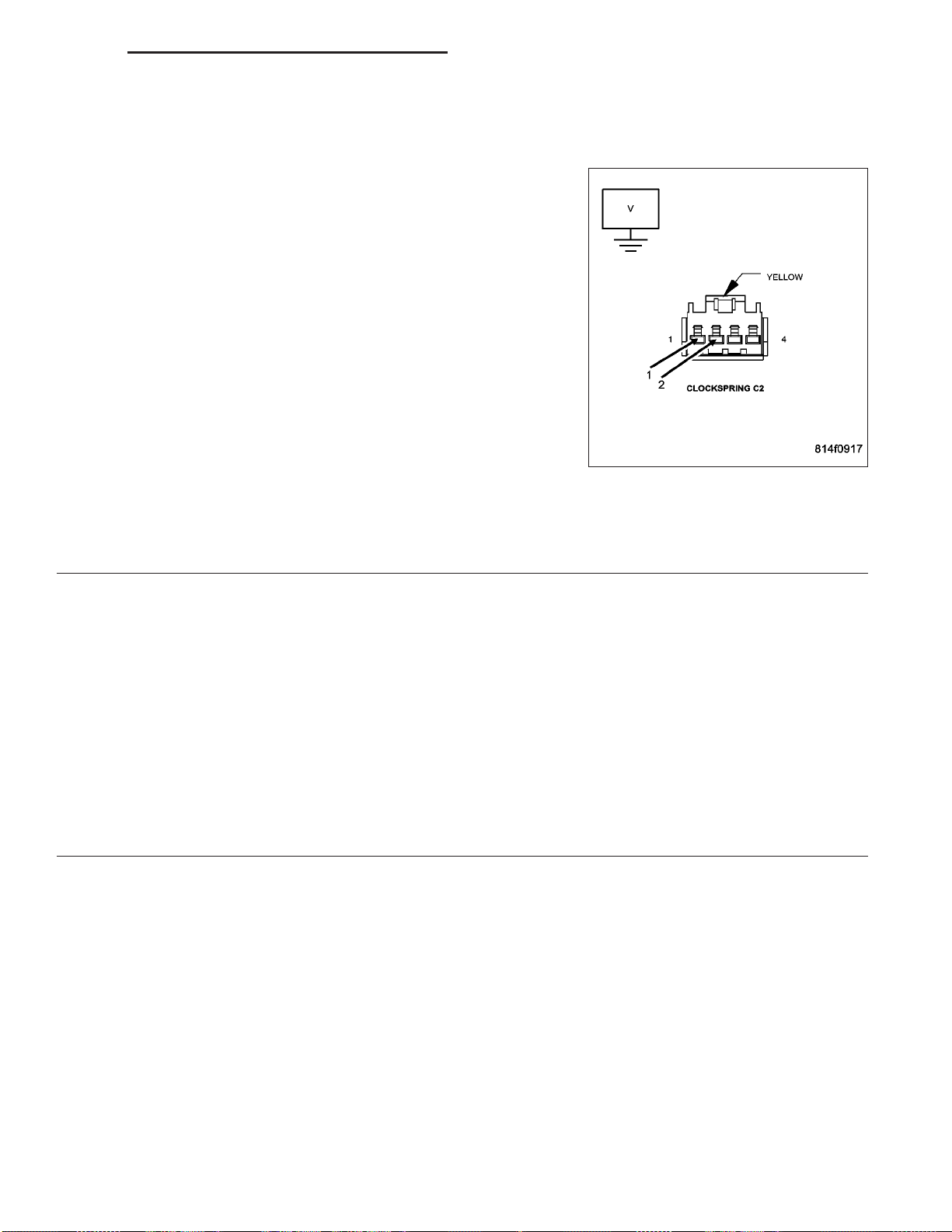
DR/DH RESTRAINTS - ELECTRICAL DIAGNOSTICS 8O - 65
DRIVER SQUIB 2 SHORT TO BATTERY (CONTINUED)
CHECK DRIVER SQUIB 2 LINE 1 CIRCUIT AND DRIVER SQUIB 2 LINE 2 CIRCUIT FOR A SHORT TO
4.
BATTERY
WARNING: To avoid personal injury or death, turn the ignition off,
disconnect the battery and wait two minutes before proceeding.
Disconnect the 8443 Load Tool and Jumper from the Clockspring connector.
Disconnect the ORC connectors.
NOTE: Check connectors - Clean and repair as necessary.
Connect the 8443 Load Tool ORC Adaptor to the ORC C2 connector.
WARNING: To avoid personal injury or death, turn the ignition on,
then reconnect the battery.
Measure the voltage of the Driver Squib 2 Line 1 circuit between the
Clockspring connector and ground.
Measure the voltage of the Driver Squib 2 Line 2 circuit between the
Clockspring connector and ground.
Is there any voltage present for either measurement?
Yes >>
No >>
REPLACE THE ORC
5.
WARNING: To avoid personal injury or death, turn the ignition off, disconnect the battery and wait two minutes before proceeding.
WARNING: If the Occupant Restraint Controller (ORC) is dropped at any time, it must be replaced. Failure to
take the proper precautions can result in accidental airbag deployment and personal injury or death.
NOTE: When reconnecting airbag system components the Ignition must be turned off and the Battery must
be disconnected.
Repair
Repair the Driver Squib 2 circuits with voltage present for
a short to Battery.
Perform ORC VERIFICATION TEST - VER 1
Go To 5
Replace the ORC in accordance with the Service Information.
Perform ORC VERIFICATION TEST - VER 1

8O - 66 RESTRAINTS - ELECTRICAL DIAGNOSTICS DR/DH
DRIVER SQUIB 2 SHORT TO BATTERY (CONTINUED)
STORED ORC DTC
6.
With the scan tool, record and erase all DTC’s from all Airbag System Modules.
If any ACTIVE codes are present they must be resolved before diagnosing any stored codes.
WARNING: To avoid personal injury or death, turn the ignition off, disconnect the battery and wait two minutes before proceeding.
Using the wiring diagram/schematic as a guide, inspect the wiring and connectors.
Look for chaffed, pierced, pinched, or partially broken wires and broken, bent, pushed out, spread, corroded, or
contaminated terminals.
The following additional checks may assist you in identifying a possible intermittent problem.
Reconnect any disconnected components and harness connector.
WARNING: To avoid personal injury or death, turn the ignition on, then reconnect the battery.
With the scan tool monitor active codes as you work through the following steps.
Wiggle the wiring harness and connectors of the related airbag circuit or component.
If codes are related to the Driver Airbag circuits, rotate the steering wheel from stop to stop.
If only stored codes return continue the test until the problem area has been isolated.
In the previous steps you have attempted to recreate the conditions responsible for setting active DTC’s in question.
Are any ACTIVE DTC’s present?
Yes >>
No >>
Select the appropriate diagnostic procedure from the Table of Contents in this section.
No problem found at this time. Erase all codes before returning vehicle to customer.

DR/DH RESTRAINTS - ELECTRICAL DIAGNOSTICS 8O - 67
DRIVER SQUIB 2 SHORT TO GROUND

8O - 68 RESTRAINTS - ELECTRICAL DIAGNOSTICS DR/DH
DRIVER SQUIB 2 SHORT TO GROUND (CONTINUED)
For the Air Bag System circuit diagram (Refer to 8 - ELECTRICAL/RESTRAINTS - SCHEMATICS AND DIAGRAMS).
For a complete wiring diagram Refer to Section 8W.
• When Monitored:
With the ignition on, the Occupant Restraint Controller (ORC) monitors the resistance of the Driver Squib 2
circuits.
• Set Condition:
The ORC has detected low resistance on the Driver Squib 2 circuits.
Possible Causes
DRIVER SQUIB 2 LINE 1 CIRCUIT OR DRIVER SQUIB 2 LINE 2 CIRCUIT SHORTED TO GROUND
CLOCKSPRING
DRIVER AIRBAG
ORC
Diagnostic Test
DETERMINE ACTIVE OR STORED DTC
1.
NOTE: Ensure the battery is fully charged.
NOTE: The scan tool, SRS Airbag Load Tool MRL 8443, and DVOM are required to perform the following
test.
NOTE: When reconnecting airbag system components the Ignition must be turned off and the Battery must
be disconnected.
Select Active or Stored DTC.
Is the DTC active or stored?
ORC - ACTIVE DTC
Go To 2
ORC - STORED DTC
Go To 6
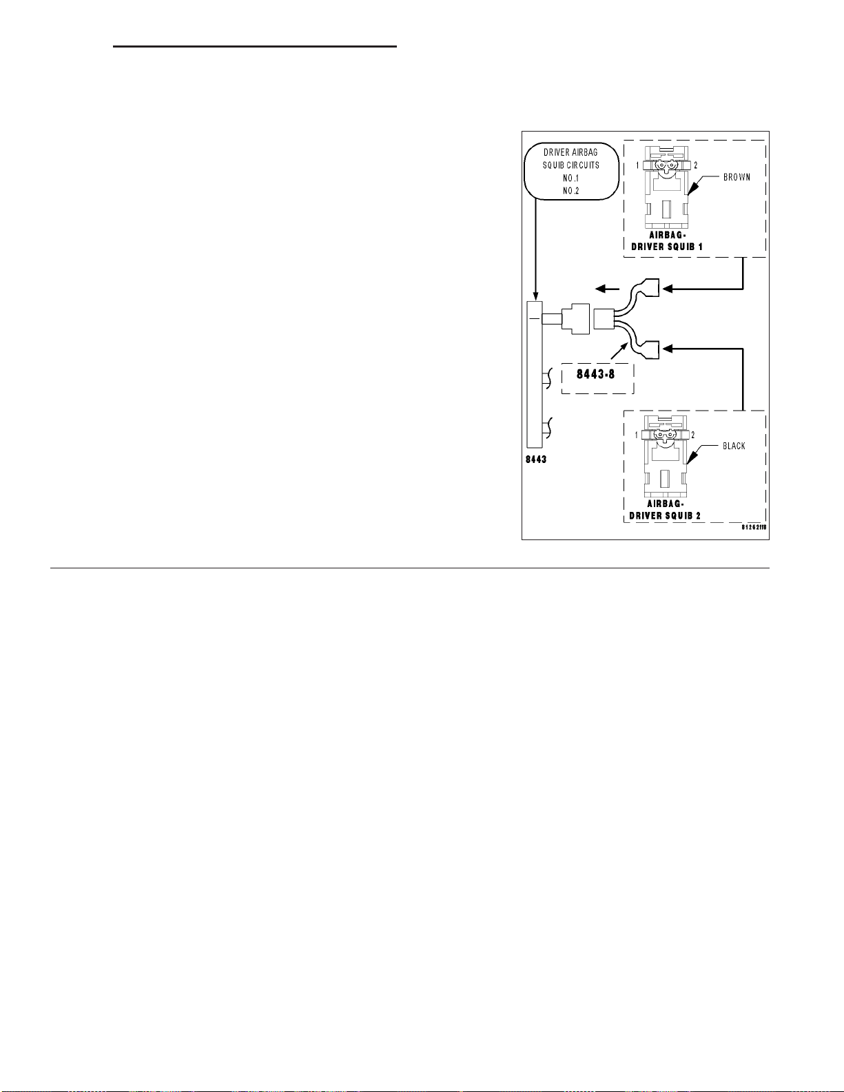
DR/DH RESTRAINTS - ELECTRICAL DIAGNOSTICS 8O - 69
DRIVER SQUIB 2 SHORT TO GROUND (CONTINUED)
CHECK FOR SHORTED SQUIB CIRCUITS IN DRIVER AIRBAG
2.
WARNING: To avoid personal injury or death, turn the ignition off,
disconnect the battery and wait two minutes before proceeding.
Disconnect the Driver Airbag Squib connectors.
WARNING: To avoid personal injury or death, do not place an
intact undeployed airbag face down on a hard surface, the airbag
will propel into the air if accidentally deployed.
NOTE: Check connectors - Clean and repair as necessary.
Connect the 8443 Load Tool and appropriate Jumper to the Driver Airbag Squib connectors.
WARNING: To avoid personal injury or death, turn the ignition on,
then reconnect the battery.
With the scan tool, read the active ORC DTC’s.
Does the scan tool display: DRIVER SQUIB 2 SHORT TO
GROUND?
Yes >>
No >>
Go To 3
Replace the Driver Airbag in accordance with the Service
Information.
Perform ORC VERIFICATION TEST - VER 1
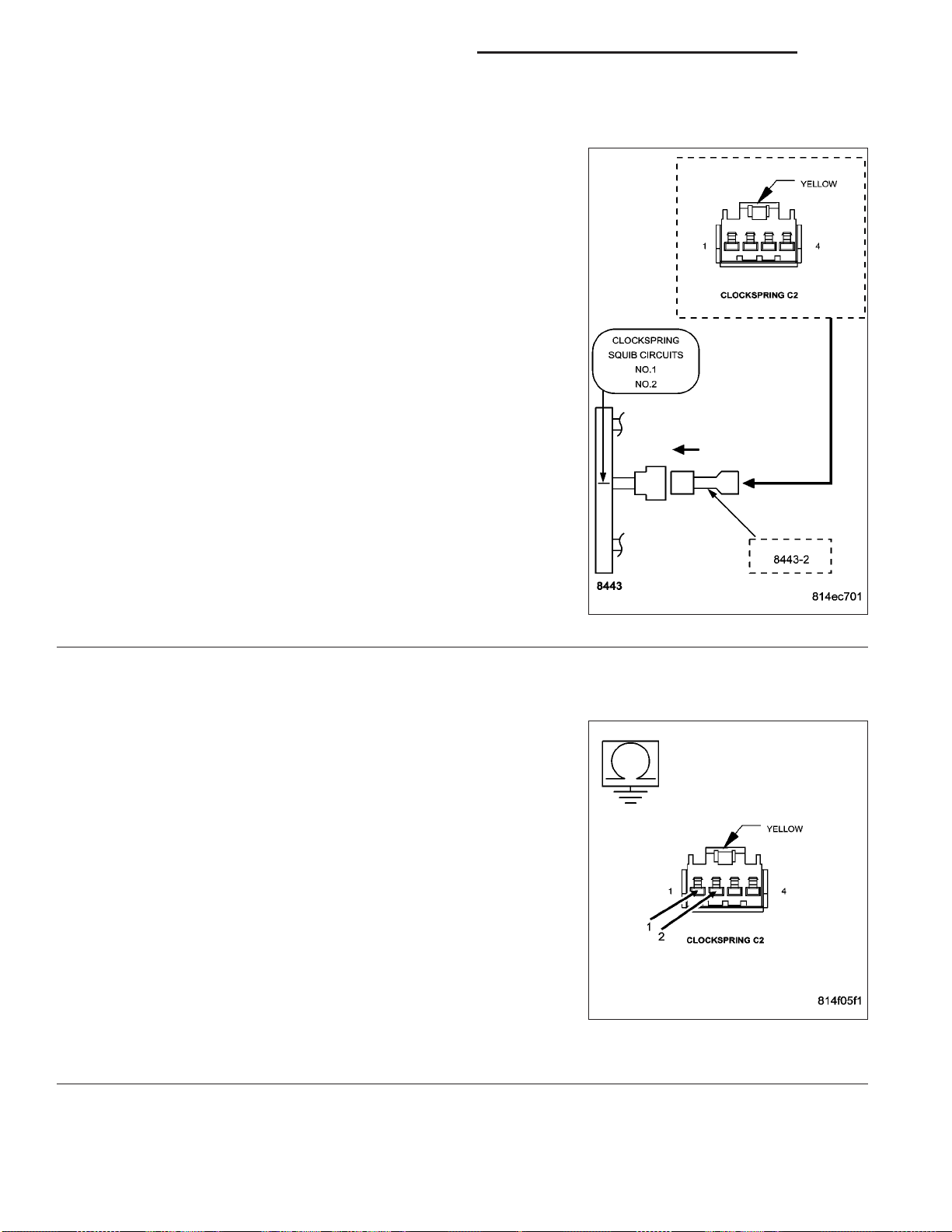
8O - 70 RESTRAINTS - ELECTRICAL DIAGNOSTICS DR/DH
DRIVER SQUIB 2 SHORT TO GROUND (CONTINUED)
CHECK CLOCKSPRING SQUIB CIRCUITS FOR A SHORT TO GROUND
3.
WARNING: To avoid personal injury or death, turn the ignition off,
disconnect the battery and wait two minutes before proceeding.
Disconnect the 8443 Load Tool Jumper from the Driver Airbag Squib
connectors.
Disconnect the Clockspring connector.
NOTE: Check connectors - Clean and repair as necessary.
Connect the 8443 Load Tool and appropriate Jumper to the Clockspring connector.
WARNING: To avoid personal injury or death, turn the ignition on,
then reconnect the battery.
With the scan tool, read the active ORC DTC’s.
Does the scan tool display: DRIVER SQUIB 2 SHORT TO
GROUND?
Yes >>
No >>
CHECK DRIVER SQUIB 2 LINE 1 CIRCUIT AND DRIVER SQUIB 2 LINE 2 CIRCUIT FOR A SHORT TO
4.
GROUND
WARNING: To avoid personal injury or death, turn the ignition off,
disconnect the battery and wait two minutes before proceeding.
Disconnect the 8443 Load Tool and Jumper from the Clockspring connector.
Disconnect the ORC connectors.
NOTE: Check connectors - Clean and repair as necessary.
Connect the 8443 Load Tool ORC Adaptor to the ORC connector.
Measure the resistance of the Driver Squib 2 Line 1 circuit between
ground and the Clockspring connector.
Measure the resistance of the Driver Squib 2 Line 2 circuit between
ground and the Clockspring connector.
Go To 4
Replace the Clockspring in accordance with the Service
Information.
Perform ORC VERIFICATION TEST - VER 1
Is the resistance below 10K ohms for either measurement?
Yes >>
No >>
Repair the Driver Squib 2 circuits with a resistance below
10K ohms for a short to ground.
Perform ORC VERIFICATION TEST - VER 1
Go To 5

DR/DH RESTRAINTS - ELECTRICAL DIAGNOSTICS 8O - 71
DRIVER SQUIB 2 SHORT TO GROUND (CONTINUED)
REPLACE THE ORC
5.
WARNING: If the Occupant Restraint Controller (ORC) is dropped at any time, it must be replaced. Failure to
take the proper precautions can result in accidental airbag deployment and personal injury or death.
NOTE: When reconnecting airbag system components the Ignition must be turned off and the Battery must
be disconnected.
Repair
Replace the ORC in accordance with the Service Information.
Perform ORC VERIFICATION TEST - VER 1
STORED ORC DTC
6.
With the scan tool, record and erase all DTC’s from all Airbag System Modules.
If any ACTIVE codes are present they must be resolved before diagnosing any stored codes.
WARNING: To avoid personal injury or death, turn the ignition off, disconnect the battery and wait two minutes before proceeding.
Using the wiring diagram/schematic as a guide, inspect the wiring and connectors.
Look for chaffed, pierced, pinched, or partially broken wires and broken, bent, pushed out, spread, corroded, or
contaminated terminals.
The following additional checks may assist you in identifying a possible intermittent problem.
Reconnect any disconnected components and harness connector.
WARNING: To avoid personal injury or death, turn the ignition on, then reconnect the battery.
With the scan tool monitor active codes as you work through the following steps.
Wiggle the wiring harness and connectors of the related airbag circuit or component.
If codes are related to the Driver Airbag circuits, rotate the steering wheel from stop to stop.
If only stored codes return continue the test until the problem area has been isolated.
In the previous steps you have attempted to recreate the conditions responsible for setting active DTC in question.
Are any ACTIVE DTCs present?
Yes >>
No >>
Select the appropriate diagnostic procedure from the Table of Contents in this section.
No problem found at this time. Erase all codes before returning vehicle to customer.
8O - 72 RESTRAINTS - ELECTRICAL DIAGNOSTICS DR/DH
INTERNAL 1
For a complete wiring diagram Refer to Section 8W.
• When Monitored:
With the ignition on. The module’s on board diagnostics continuously performs internal circuit tests.
• Set Condition:
This DTC will set if the module identifies an out of range internal circuit.
Possible Causes
OCCUPANT RESTRAINT CONTROLLER
Diagnostic Test
REPLACE OCCUPANT RESTRAINT CONTROLLER
1.
Turn the ignition on.
With the scan tool, erase and read ORC DTCs.
WARNING: To avoid personal injury or death, turn
the ignition off, disconnect the battery and wait
two minutes before proceeding.
WARNING: If the Occupant Restraint Controller is
dropped at any time, it must be replaced. Failure
to take proper precautions could result in accidental airbag deployment and personal injury or
death.
When this code is set, view repair.
Repair
Replace the Occupant Restraint Controller
in accordance with the Service Information.
Perform the ORC VERIFICATION TESTVER. 1.

DR/DH RESTRAINTS - ELECTRICAL DIAGNOSTICS 8O - 73
INTERNAL 2
For a complete wiring diagram Refer to Section 8W.
• When Monitored:
With the ignition on. The module’s on board diagnostics continuously performs internal circuit tests.
• Set Condition:
This DTC will set if the module identifies an out of range internal circuit.
Possible Causes
OCCUPANT RESTRAINT CONTROLLER
Diagnostic Test
REPLACE OCCUPANT RESTRAINT CONTROLLER
1.
Turn the ignition on.
With the scan tool, erase and read ORC DTCs.
WARNING: To avoid personal injury or death, turn
the ignition off, disconnect the battery and wait
two minutes before proceeding.
WARNING: If the Occupant Restraint Controller is
dropped at any time, it must be replaced. Failure
to take proper precautions could result in accidental airbag deployment and personal injury or
death.
When this code is set, view repair.
Repair
Replace the Occupant Restraint Controller
in accordance with the Service Information.
Perform the ORC VERIFICATION TESTVER. 1.
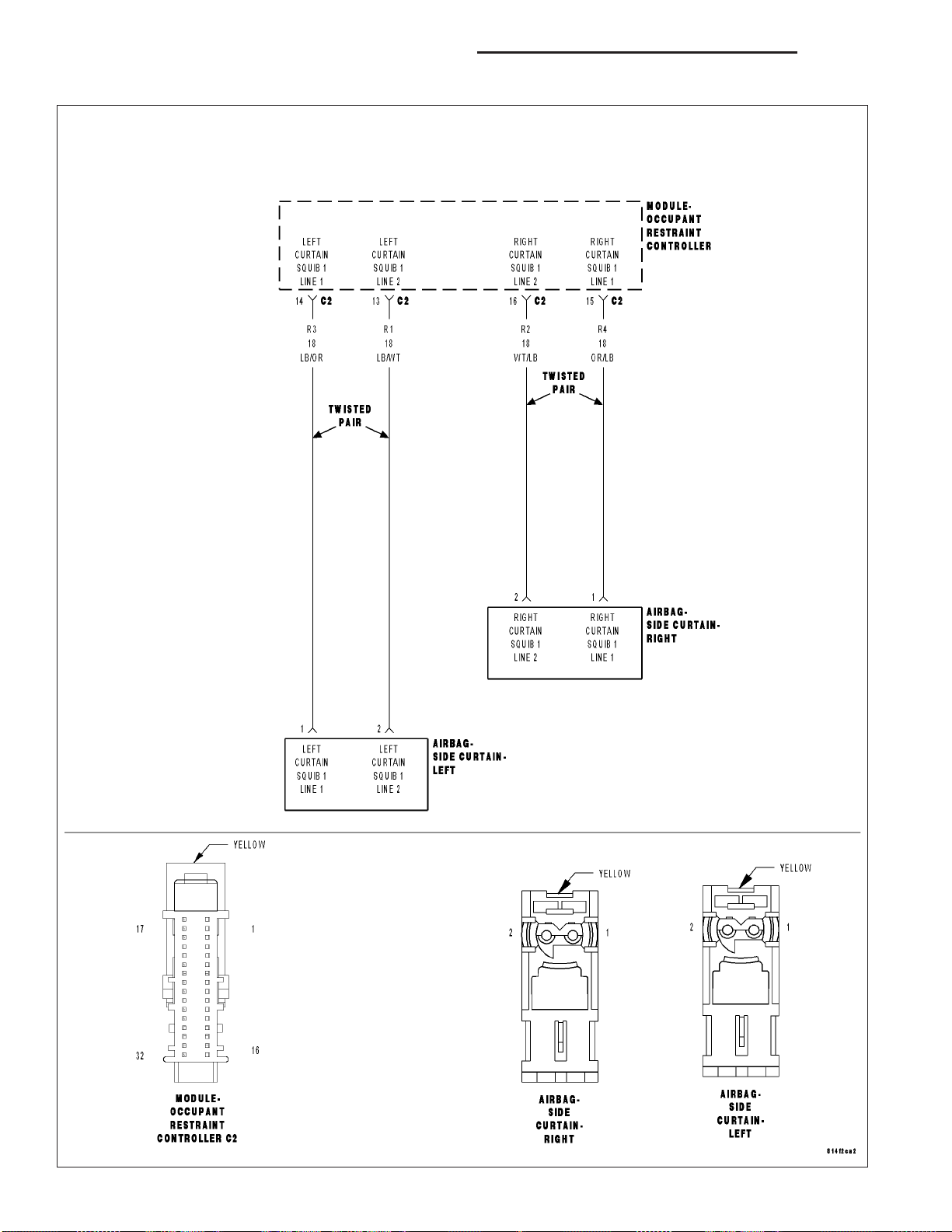
8O - 74 RESTRAINTS - ELECTRICAL DIAGNOSTICS DR/DH
LEFT CURTAIN SQUIB 1 CIRCUIT OPEN

DR/DH RESTRAINTS - ELECTRICAL DIAGNOSTICS 8O - 75
LEFT CURTAIN SQUIB 1 CIRCUIT OPEN (CONTINUED)
For the Air Bag System circuit diagram (Refer to 8 - ELECTRICAL/RESTRAINTS - SCHEMATICS AND DIAGRAMS).
For a complete wiring diagram Refer to Section 8W.
• When Monitored:
With the ignition on, the Occupant Restraint Controller (ORC) monitors the resistance of the Left Curtain Squib
1 circuits.
• Set Condition:
The ORC has detected an open or high resistance on the Left Curtain Squib 1 circuits.
Possible Causes
(R3) LEFT CURTAIN SQUIB 1 LINE 1 CIRCUIT OPEN
(R1) LEFT CURTAIN SQUIB 1 LINE 2 CIRCUIT OPEN
LEFT SIDE CURTAIN AIRBAG
ORC
Diagnostic Test
DETERMINE ACTIVE OR STORED DTC
1.
NOTE: Ensure the battery is fully charged.
NOTE: The scan tool, SRS Airbag Load Tool MRL 8443, and DVOM are required to perform the following
test.
NOTE: When reconnecting airbag system components the Ignition must be turned off and the Battery must
be disconnected.
Select Active or Stored DTC.
Is the DTC active or stored?
ORC - ACTIVE DTC
Go To 2
ORC - STORED DTC
Go To 6

8O - 76 RESTRAINTS - ELECTRICAL DIAGNOSTICS DR/DH
LEFT CURTAIN SQUIB 1 CIRCUIT OPEN (CONTINUED)
CHECK FOR OPEN SQUIB CIRCUITS IN LEFT SIDE CURTAIN AIRBAG
2.
WARNING: To avoid personal injury or death, turn the ignition off,
disconnect the battery and wait two minutes before proceeding.
Disconnect the Left Side Curtain Airbag connector.
WARNING: To avoid personal injury or death, do not place an
intact undeployed curtain airbag face down on a hard surface, the
airbag will propel into the air if accidentally deployed.
NOTE: Check connectors - Clean and repair as necessary.
Connect the 8443 Load Tool and appropriate Jumper to the Left Side
Curtain Airbag connector.
WARNING: To avoid personal injury or death, turn the ignition on,
then reconnect the battery.
With the scan tool, read the active ORC DTC’s.
Does the scan tool display: LEFT CURTAIN SQUIB 1 CIRCUIT
OPEN?
Yes >>
No >>
CHECK (R3) LEFT CURTAIN SQUIB 1 LINE 1 CIRCUIT FOR
3.
AN OPEN
WARNING: To avoid personal injury or death, turn the ignition off,
disconnect the battery and wait two minutes before proceeding.
Disconnect the 8443 Load Tool and Jumper from the Left Side Curtain
Airbag connector.
Disconnect the ORC connectors.
NOTE: Check connectors - Clean and repair as necessary.
Connect the 8443 Load Tool ORC Adaptor to the ORC connector.
Measure the resistance of the (R3) Left Curtain Squib 1 Line 1 circuit
between the Left Side Curtain Airbag connector and the Load Tool
ORC Adaptor.
Go To 3
Replace the Left Side Curtain Airbag in accordance with
the Service Information.
Perform ORC VERIFICATION TEST - VER 1
Is the resistance below 1.0 ohm?
Yes >>
No >>
Go To 4
Repair the (R3) Left Curtain Squib 1 Line 1 circuit for an
open. Then, Go To 4
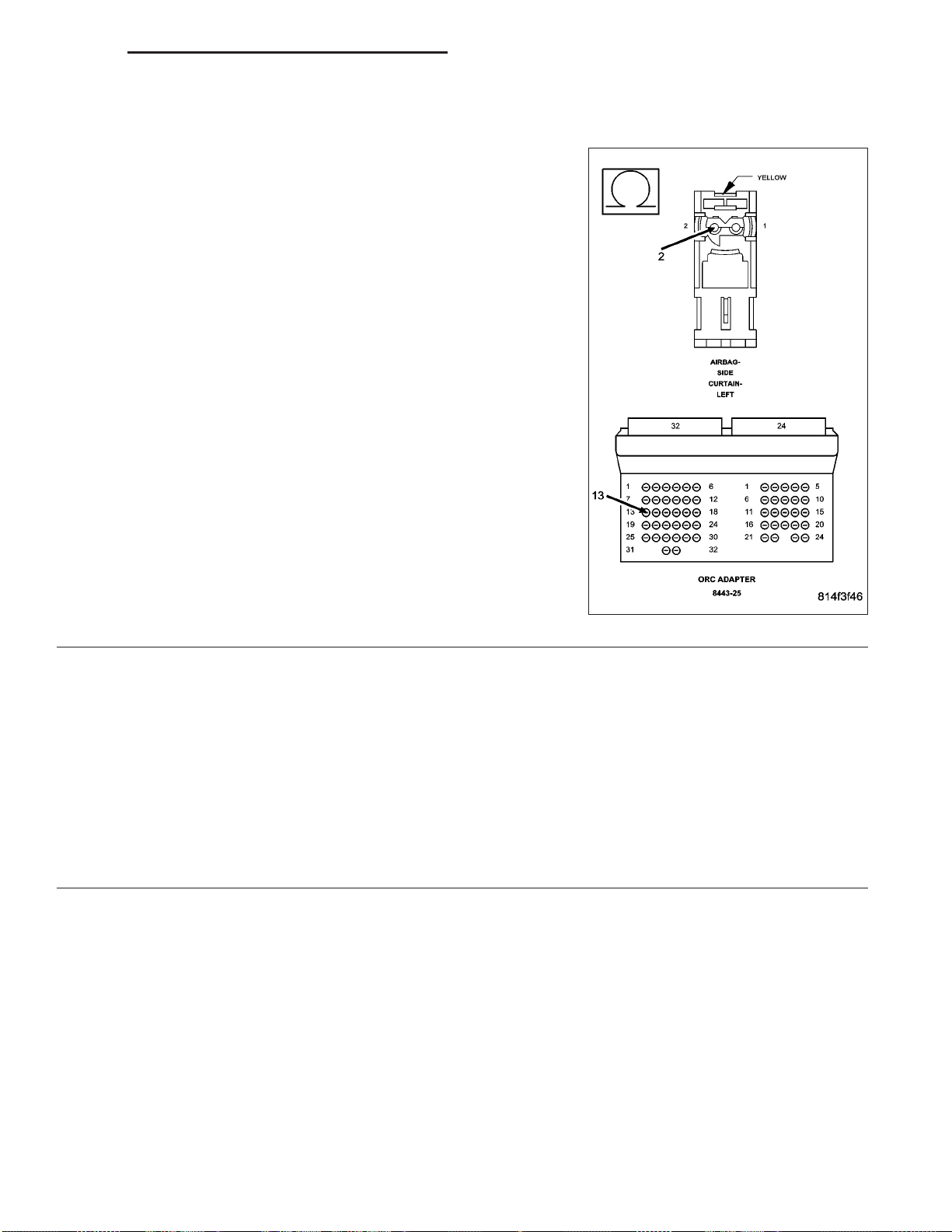
DR/DH RESTRAINTS - ELECTRICAL DIAGNOSTICS 8O - 77
LEFT CURTAIN SQUIB 1 CIRCUIT OPEN (CONTINUED)
CHECK (R1) LEFT CURTAIN SQUIB 1 LINE 2 CIRCUIT FOR AN OPEN
4.
Measure the resistance of the (R1) Left Curtain Squib 1 Line 2 circuit
between the Left Side Curtain Airbag connector and the Load Tool
ORC Adaptor.
Is the resistance below 1.0 ohm?
Yes >>
No >>
REPLACE THE ORC
5.
WARNING: If the Occupant Restraint Controller (ORC) is dropped at any time, it must be replaced. Failure to
take the proper precautions can result in accidental airbag deployment and personal injury or death.
NOTE: When reconnecting airbag system components the Ignition must be turned off and the Battery must
be disconnected.
Go To 5
Repair the (R1) Left Curtain Squib 1 Line 2 circuit for an
open.
Perform ORC VERIFICATION TEST - VER 1
Repair
Replace the ORC in accordance with the Service Information.
Perform ORC VERIFICATION TEST - VER 1

8O - 78 RESTRAINTS - ELECTRICAL DIAGNOSTICS DR/DH
LEFT CURTAIN SQUIB 1 CIRCUIT OPEN (CONTINUED)
STORED ORC DTC
6.
With the scan tool, record and erase all DTC’s from all Airbag System Modules.
If any ACTIVE codes are present they must be resolved before diagnosing any stored codes.
WARNING: To avoid personal injury or death, turn the ignition off, disconnect the battery and wait two minutes before proceeding.
Using the wiring diagram/schematic as a guide, inspect the wiring and connectors.
Look for chaffed, pierced, pinched, or partially broken wires and broken, bent, pushed out, spread, corroded, or
contaminated terminals.
The following additional checks may assist you in identifying a possible intermittent problem.
Reconnect any disconnected components and harness connector.
WARNING: To avoid personal injury or death, turn the ignition on, then reconnect the battery.
With the scan tool monitor active codes as you work through the following steps.
Wiggle the wiring harness and connectors of the related airbag circuit or component.
If codes are related to the Driver Airbag circuits, rotate the steering wheel from stop to stop.
If only stored codes return continue the test until the problem area has been isolated.
In the previous steps you have attempted to recreate the conditions responsible for setting active DTC in question.
Are any ACTIVE DTCs present?
Yes >>
No >>
Select the appropriate diagnostic procedure from the Table of Contents in this section.
No problem found at this time. Erase all codes before returning vehicle to customer.
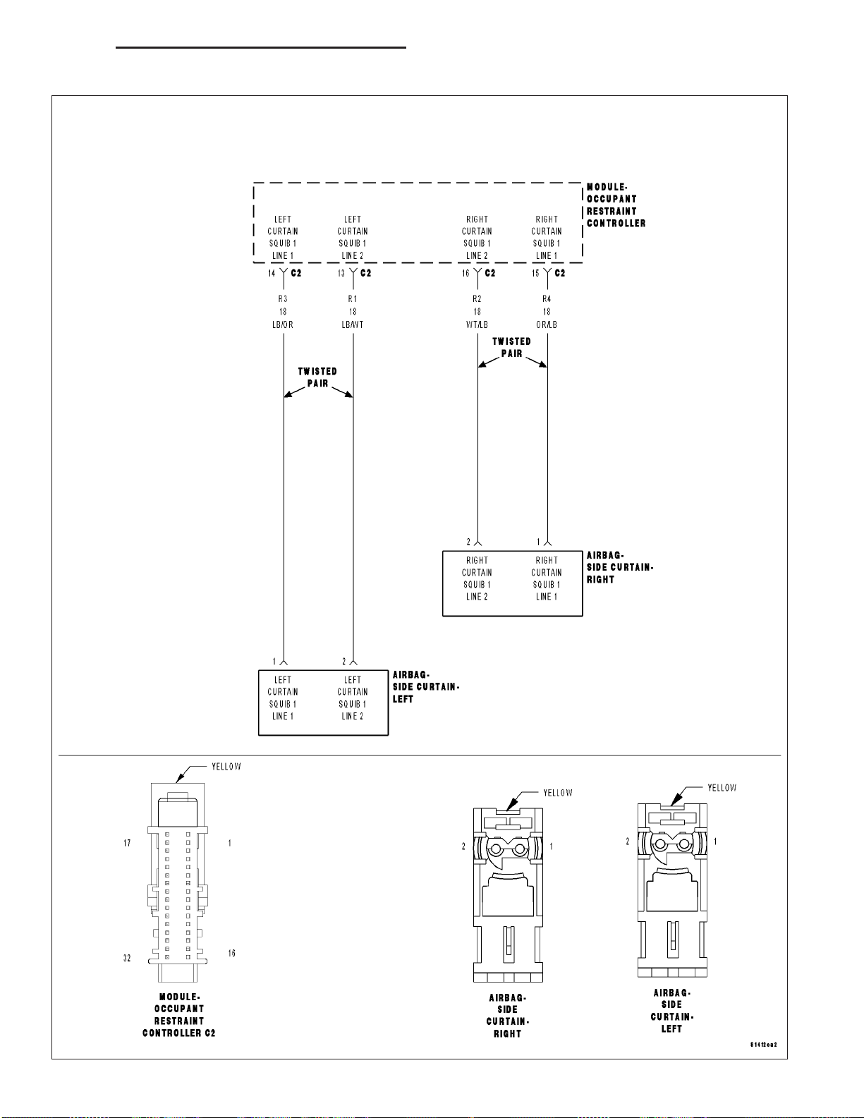
DR/DH RESTRAINTS - ELECTRICAL DIAGNOSTICS 8O - 79
LEFT CURTAIN SQUIB 1 CIRCUIT SHORT

8O - 80 RESTRAINTS - ELECTRICAL DIAGNOSTICS DR/DH
LEFT CURTAIN SQUIB 1 CIRCUIT SHORT (CONTINUED)
For the Air Bag System circuit diagram (Refer to 8 - ELECTRICAL/RESTRAINTS - SCHEMATICS AND DIAGRAMS).
For a complete wiring diagram Refer to Section 8W.
• When Monitored:
With the ignition on, the Occupant Restraint Controller (ORC) monitors the resistance of the Left Curtain Squib
1 circuits.
• Set Condition:
The ORC has detected low resistance between the Left Curtain Squib 1 circuits.
Possible Causes
(R3) LEFT CURTAIN SQUIB 1 LINE 1 CIRCUIT SHORTED TO (R1) LEFT CURTAIN SQUIB 1 LINE 2 CIRCUIT
LEFT SIDE CURTAIN AIRBAG
ORC
Diagnostic Test
DETERMINE ACTIVE OR STORED DTC
1.
NOTE: Ensure the battery is fully charged.
NOTE: The scan tool, SRS Airbag Load Tool MRL 8443, and DVOM are required to perform the following
test.
NOTE: When reconnecting airbag system components the Ignition must be turned off and the Battery must
be disconnected.
Select Active or Stored DTC.
Is the DTC active or stored?
ORC - ACTIVE DTC
Go To 2
ORC - STORED DTC
Go To 5

DR/DH RESTRAINTS - ELECTRICAL DIAGNOSTICS 8O - 81
LEFT CURTAIN SQUIB 1 CIRCUIT SHORT (CONTINUED)
CHECK FOR SHORTED SQUIB CIRCUITS IN LEFT SIDE CURTAIN AIRBAG
2.
WARNING: To avoid personal injury or death, turn the ignition off,
disconnect the battery and wait two minutes before proceeding.
Disconnect the Left Side Curtain Airbag connector.
WARNING: To avoid personal injury or death, do not place an
intact undeployed curtain airbag face down on a hard surface, the
airbag will propel into the air if accidentally deployed.
NOTE: Check connectors - Clean and repair as necessary.
Connect the 8443 Load Tool and appropriate Jumper to the Left Side
Curtain Airbag connector.
WARNING: To avoid personal injury or death, turn the ignition on,
then reconnect the battery.
With the scan tool, read the active ORC DTC’s.
Does the scan tool display: LEFT CURTAIN SQUIB 1 CIRCUIT
SHORT?
Yes >>
No >>
Go To 3
Replace the Left Side Curtain Airbag in accordance with
the Service Information.
Perform ORC VERIFICATION TEST - VER 1
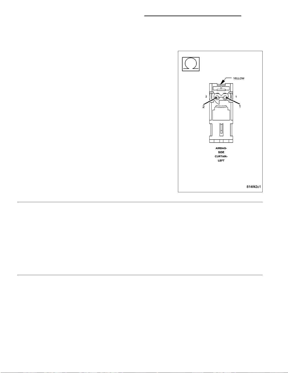
8O - 82 RESTRAINTS - ELECTRICAL DIAGNOSTICS DR/DH
LEFT CURTAIN SQUIB 1 CIRCUIT SHORT (CONTINUED)
CHECK (R3) LEFT CURTAIN SQUIB 1 LINE 1 CIRCUIT FOR A SHORT TO (R1) LEFT CURTAIN SQUIB 1
3.
LINE 2 CIRCUIT
WARNING: To avoid personal injury or death, turn the ignition off,
disconnect the battery and wait two minutes before proceeding.
Disconnect the 8443 Load Tool and Jumper from the Left Side Curtain
Airbag connector.
Disconnect the ORC connectors.
NOTE: Check connectors - Clean and repair as necessary.
Connect the 8443 Load Tool ORC Adaptor to the ORC connector.
Measure the resistance between the (R3) Left Curtain Squib 1 Line 1
circuit and the (R1) Left Curtain Squib 1 Line 2 circuit at the Left Side
Curtain Airbag connector.
Is the resistance below 10K ohms?
Yes >>
No >>
REPLACE THE ORC
4.
WARNING: If the Occupant Restraint Controller (ORC) is dropped at any time, it must be replaced. Failure to
take the proper precautions can result in accidental airbag deployment and personal injury or death.
NOTE: When reconnecting airbag system components the Ignition must be turned off and the Battery must
be disconnected.
Repair
Repair the (R3) Left Curtain Squib 1 Line 1 circuit for a
short to the (R1) Left Curtain Squib 1 Line 2 circuit.
Perform ORC VERIFICATION TEST - VER 1
Go To 4
Replace the ORC in accordance with the Service Information.
Perform ORC VERIFICATION TEST - VER 1

DR/DH RESTRAINTS - ELECTRICAL DIAGNOSTICS 8O - 83
LEFT CURTAIN SQUIB 1 CIRCUIT SHORT (CONTINUED)
STORED ORC DTC
5.
With the scan tool, record and erase all DTC’s from all Airbag System Modules.
If any ACTIVE codes are present they must be resolved before diagnosing any stored codes.
WARNING: To avoid personal injury or death, turn the ignition off, disconnect the battery and wait two minutes before proceeding.
Using the wiring diagram/schematic as a guide, inspect the wiring and connectors.
Look for chaffed, pierced, pinched, or partially broken wires and broken, bent, pushed out, spread, corroded, or
contaminated terminals.
The following additional checks may assist you in identifying a possible intermittent problem.
Reconnect any disconnected components and harness connector.
WARNING: To avoid personal injury or death, turn the ignition on, then reconnect the battery.
With the scan tool monitor active codes as you work through the following steps.
Wiggle the wiring harness and connectors of the related airbag circuit or component.
If codes are related to the Driver Airbag circuits, rotate the steering wheel from stop to stop.
If only stored codes return continue the test until the problem area has been isolated.
In the previous steps you have attempted to recreate the conditions responsible for setting active DTC in question.
Are any ACTIVE DTC’s present?
Yes >>
No >>
Select the appropriate diagnostic procedure from the Table of Contents in this section.
No problem found at this time. Erase all codes before returning vehicle to customer.

8O - 84 RESTRAINTS - ELECTRICAL DIAGNOSTICS DR/DH
LEFT CURTAIN SQUIB 1 SHORT TO BATTERY

DR/DH RESTRAINTS - ELECTRICAL DIAGNOSTICS 8O - 85
LEFT CURTAIN SQUIB 1 SHORT TO BATTERY (CONTINUED)
For the Air Bag System circuit diagram (Refer to 8 - ELECTRICAL/RESTRAINTS - SCHEMATICS AND DIAGRAMS).
For a complete wiring diagram Refer to Section 8W.
• When Monitored:
With the ignition on, the Occupant Restraint Controller (ORC) monitors the voltage on the Left Curtain Squib 1
circuits.
• Set Condition:
The ORC has detected voltage on the Left Curtain Squib 1 circuits.
Possible Causes
(R3) LEFT CURTAIN SQUIB 1 LINE 1 CIRCUIT OR (R1) LEFT CURTAIN SQUIB 1 LINE 2 CIRCUIT SHORTED
TO BATTERY
LEFT SIDE CURTAIN AIRBAG
ORC
Diagnostic Test
DETERMINE ACTIVE OR STORED DTC
1.
NOTE: Ensure the battery is fully charged.
NOTE: The scan tool, SRS Airbag Load Tool MRL 8443, and DVOM are required to perform the following
test.
NOTE: When reconnecting airbag system components the Ignition must be turned off and the Battery must
be disconnected.
Select Active or Stored DTC.
Is the DTC active or stored?
ORC - ACTIVE DTC
Go To 2
ORC - STORED DTC
Go To 5

8O - 86 RESTRAINTS - ELECTRICAL DIAGNOSTICS DR/DH
LEFT CURTAIN SQUIB 1 SHORT TO BATTERY (CONTINUED)
CHECK FOR SHORTED SQUIB CIRCUITS IN LEFT SIDE CURTAIN AIRBAG
2.
WARNING: To avoid personal injury or death, turn the ignition off,
disconnect the battery and wait two minutes before proceeding.
Disconnect the Left Side Curtain Airbag connector.
WARNING: To avoid personal injury or death, do not place an
intact undeployed curtain airbag face down on a hard surface, the
airbag will propel into the air if accidentally deployed.
NOTE: Check connectors - Clean and repair as necessary.
Connect the 8443 Load Tool and appropriate Jumper to the Left Side
Curtain Airbag connector.
WARNING: To avoid personal injury or death, turn the ignition on,
then reconnect the battery.
With the scan tool, read the active ORC DTC’s.
Does the scan tool display: LEFT CURTAIN SQUIB 1 SHORT TO
BATTERY?
Yes >>
No >>
Go To 3
Replace the Left Side Curtain Airbag in accordance with
the Service Information.
Perform ORC VERIFICATION TEST - VER 1

DR/DH RESTRAINTS - ELECTRICAL DIAGNOSTICS 8O - 87
LEFT CURTAIN SQUIB 1 SHORT TO BATTERY (CONTINUED)
CHECK (R3) LEFT CURTAIN SQUIB 1 LINE 1 CIRCUIT AND (R1) LEFT CURTAIN SQUIB 1 LINE 2
3.
CIRCUIT FOR A SHORT TO BATTERY
WARNING: To avoid personal injury or death, turn the ignition off,
disconnect the battery and wait two minutes before proceeding.
Disconnect the 8443 Load Tool and Jumper from the Left Side Curtain
Airbag connector.
Disconnect the ORC connectors.
NOTE: Check connectors - Clean and repair as necessary.
Connect the 8443 Load Tool ORC Adaptor to the ORC connector.
Measure the voltage of the (R3) Left Curtain Squib 1 Line 1 circuit
between the Left Side Curtain Airbag connector and ground.
Measure the voltage of the (R1) Left Curtain Squib 1 Line 2 circuit
between the Left Side Curtain Airbag connector and ground.
Is there any voltage present on either circuit?
Yes >>
No >>
REPLACE THE ORC
4.
WARNING: To avoid personal injury or death, turn the ignition off, disconnect the battery and wait two minutes before proceeding.
WARNING: If the Occupant Restraint Controller (ORC) is dropped at any time, it must be replaced. Failure to
take the proper precautions can result in accidental airbag deployment and personal injury or death.
NOTE: When reconnecting airbag system components the Ignition must be turned off and the Battery must
be disconnected.
Repair
Repair the Left Curtain Squib 1 circuits with voltage
present for a short to battery.
Perform ORC VERIFICATION TEST - VER 1
Go To 4
Replace the ORC in accordance with the Service Information.
Perform ORC VERIFICATION TEST - VER 1

8O - 88 RESTRAINTS - ELECTRICAL DIAGNOSTICS DR/DH
LEFT CURTAIN SQUIB 1 SHORT TO BATTERY (CONTINUED)
STORED ORC DTC
5.
With the scan tool, record and erase all DTC’s from all Airbag System Modules.
If any ACTIVE codes are present they must be resolved before diagnosing any stored codes.
WARNING: To avoid personal injury or death, turn the ignition off then disconnect the battery and wait two
minutes before proceeding.
Using the wiring diagram/schematic as a guide, inspect the wiring and connectors.
Look for chaffed, pierced, pinched, or partially broken wires and broken, bent, pushed out, spread, corroded, or
contaminated terminals.
The following additional checks may assist you in identifying a possible intermittent problem.
Reconnect any disconnected components and harness connector.
WARNING: To avoid personal injury or death, turn the ignition on, then reconnect the battery.
With the scan tool monitor active codes as you work through the following steps.
Wiggle the wiring harness and connectors of the related airbag circuit or component.
If codes are related to the Driver Airbag circuits, rotate the steering wheel from stop to stop.
If only stored codes return continue the test until the problem area has been isolated.
In the previous steps you have attempted to recreate the conditions responsible for setting active DTC in question.
Are any ACTIVE DTCs present?
Yes >>
No >>
Select the appropriate diagnostic procedure from the Table of Contents in this section.
No problem found at this time. Erase all codes before returning vehicle to customer.

DR/DH RESTRAINTS - ELECTRICAL DIAGNOSTICS 8O - 89
LEFT CURTAIN SQUIB 1 SHORT TO GROUND

8O - 90 RESTRAINTS - ELECTRICAL DIAGNOSTICS DR/DH
LEFT CURTAIN SQUIB 1 SHORT TO GROUND (CONTINUED)
For the Air Bag System circuit diagram (Refer to 8 - ELECTRICAL/RESTRAINTS - SCHEMATICS AND DIAGRAMS).
For a complete wiring diagram Refer to Section 8W.
• When Monitored:
With the ignition on, the Occupant Restraint Controller (ORC) monitors the resistance of the Left Curtain Squib
1 circuits.
• Set Condition:
The ORC has detected low resistance of the Left Curtain Squib 1 circuits.
Possible Causes
(R3) LEFT CURTAIN SQUIB 1 LINE 1 CIRCUIT OR (R1) LEFT CURTAIN SQUIB 1 LINE 2 CIRCUIT SHORTED
TO GROUND
LEFT SIDE CURTAIN AIRBAG
ORC
Diagnostic Test
DETERMINE ACTIVE OR STORED DTC
1.
NOTE: Ensure the battery is fully charged.
NOTE: The scan tool, SRS Airbag Load Tool MRL 8443, and DVOM are required to perform the following
test.
NOTE: When reconnecting airbag system components the Ignition must be turned off and the Battery must
be disconnected.
Select Active or Stored DTC.
Is the DTC active or stored?
ORC - ACTIVE DTC
Go To 2
ORC - STORED DTC
Go To 5

DR/DH RESTRAINTS - ELECTRICAL DIAGNOSTICS 8O - 91
LEFT CURTAIN SQUIB 1 SHORT TO GROUND (CONTINUED)
CHECK FOR SHORTED SQUIB CIRCUITS IN LEFT SIDE CURTAIN AIRBAG
2.
WARNING: To avoid personal injury or death, turn the ignition off,
disconnect the battery and wait two minutes before proceeding.
Disconnect the Left Side Curtain Airbag connector.
WARNING: To avoid personal injury or death, do not place an
intact undeployed curtain airbag face down on a hard surface, the
airbag will propel into the air if accidentally deployed.
NOTE: Check connectors - Clean and repair as necessary.
Connect the 8443 Load Tool and appropriate Jumper to the Left Side
Curtain Airbag connector.
WARNING: To avoid personal injury or death, turn the ignition on,
then reconnect the battery.
With the scan tool, read the active ORC DTC’s.
Does the scan tool display: LEFT CURTAIN SQUIB 1 SHORT TO
GROUND?
Yes >>
No >>
CHECK (R3) LEFT CURTAIN SQUIB 1 LINE 1 CIRCUIT AND (R1) LEFT CURTAIN SQUIB 1 LINE 2
3.
CIRCUIT FOR A SHORT TO GROUND
WARNING: To avoid personal injury or death, turn the ignition off,
disconnect the battery and wait two minutes before proceeding.
Disconnect the 8443 Load Tool and Jumper from the Left Side Curtain
Airbag connector.
Disconnect the ORC connectors.
NOTE: Check connectors - Clean and repair as necessary.
Connect the 8443 Load Tool ORC Adaptor to the ORC connector.
Measure the resistance of the (R3) Left Curtain Squib 1 Line 1 circuit
between ground and the Left Side Curtain Airbag connector.
Measure the resistance of the (R1) Left Curtain Squib 1 Line 2 circuit
between ground and the Left Side Curtain Airbag connector.
Go To 3
Replace the Left Side Curtain Airbag in accordance with
the Service Information.
Perform ORC VERIFICATION TEST - VER 1
Is the resistance below 10K ohms on either circuit?
Yes >>
No >>
Repair the Left Curtain Squib 1 circuits with a resistance
below 10K ohms for a short to ground.
Perform ORC VERIFICATION TEST - VER 1
Go To 4

8O - 92 RESTRAINTS - ELECTRICAL DIAGNOSTICS DR/DH
LEFT CURTAIN SQUIB 1 SHORT TO GROUND (CONTINUED)
REPLACE THE ORC
4.
WARNING: If the Occupant Restraint Controller (ORC) is dropped at any time, it must be replaced. Failure to
take the proper precautions can result in accidental airbag deployment and personal injury or death.
NOTE: When reconnecting airbag system components the Ignition must be turned off and the Battery must
be disconnected.
Repair
Replace the ORC in accordance with the Service Information.
Perform ORC VERIFICATION TEST - VER 1
STORED ORC DTC
5.
With the scan tool, record and erase all DTC’s from all Airbag System Modules.
If any ACTIVE codes are present they must be resolved before diagnosing any stored codes.
WARNING: To avoid personal injury or death, turn the ignition off, disconnect the battery and wait two minutes before proceeding.
Using the wiring diagram/schematic as a guide, inspect the wiring and connectors.
Look for chaffed, pierced, pinched, or partially broken wires and broken, bent, pushed out, spread, corroded, or
contaminated terminals.
The following additional checks may assist you in identifying a possible intermittent problem.
Reconnect any disconnected components and harness connector.
WARNING: To avoid personal injury or death, turn the ignition on, then reconnect the battery.
With the scan tool monitor active codes as you work through the following steps.
Wiggle the wiring harness and connectors of the related airbag circuit or component.
If codes are related to the Driver Airbag circuits, rotate the steering wheel from stop to stop.
IF only stored codes return continue the test until the problem area has been isolated.
In the previous steps you have attempted to recreate the conditions responsible for setting active DTC in question.
Are any ACTIVE DTC’s present?
Yes >>
No >>
Select the appropriate diagnostic procedure from the Table of Contents in this section.
No problem found at this time. Erase all codes before returning vehicle to customer.
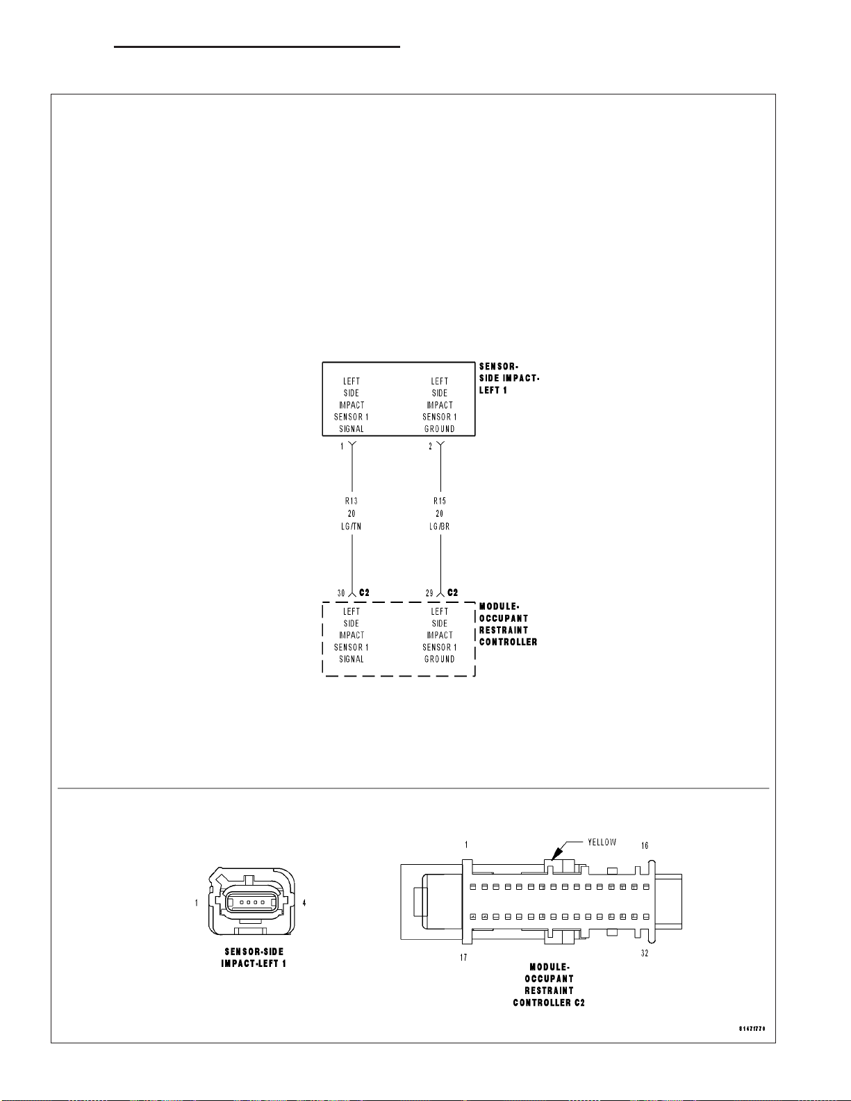
DR/DH RESTRAINTS - ELECTRICAL DIAGNOSTICS 8O - 93
LEFT SIDE IMPACT SENSOR 1 INTERNAL 1

8O - 94 RESTRAINTS - ELECTRICAL DIAGNOSTICS DR/DH
LEFT SIDE IMPACT SENSOR 1 INTERNAL 1 (CONTINUED)
For the Airbag System circuit diagram (Refer to 8 - ELECTRICAL/RESTRAINTS - SCHEMATICS AND DIAGRAMS).
For a complete wiring diagram Refer to Section 8W.
• When Monitored:
The Occupant Restraint Controller (ORC) continuously communicates with the Left Side Impact Sensor 1 over
the sensor signal circuit. The sensor communication and on board diagnostics are powered by the ORC signal.
• Set Condition:
This code will set, if the ORC and the Left Side Impact Sensor 1 do not establish and maintain valid data
communications.
Possible Causes
(R13) LEFT SIDE IMPACT SENSOR 1 SIGNAL CIRCUIT SHORTED TO BATTERY
(R13) LEFT SIDE IMPACT SENSOR 1 SIGNAL CIRCUIT SHORTED TO GROUND
(R13, R15) LEFT SIDE IMPACT SENSOR 1 CIRCUITS SHORTED TOGETHER
(R15) LEFT SIDE IMPACT SENSOR 1 GROUND CIRCUIT OPEN
(R13) LEFT SIDE IMPACT SENSOR 1 SIGNAL CIRCUIT OPEN
ORC, LEFT SIDE IMPACT SENSOR 1
Diagnostic Test
VERIFY THAT DTC LEFT SIDE IMPACT SENSOR 1 INTERNAL 1 IS ACTIVE
1.
NOTE: Ensure the battery is fully charged.
NOTE: When reconnecting Airbag system components, the ignition must be turned off and the battery must
be disconnected.
Turn the ignition on.
With the scan tool, read ORC DTCs.
Does the scan tool display active: LEFT SIDE IMPACT SENSOR 1 INTERNAL 1?
Yes >>
No >>
Go To 2
Go To 9
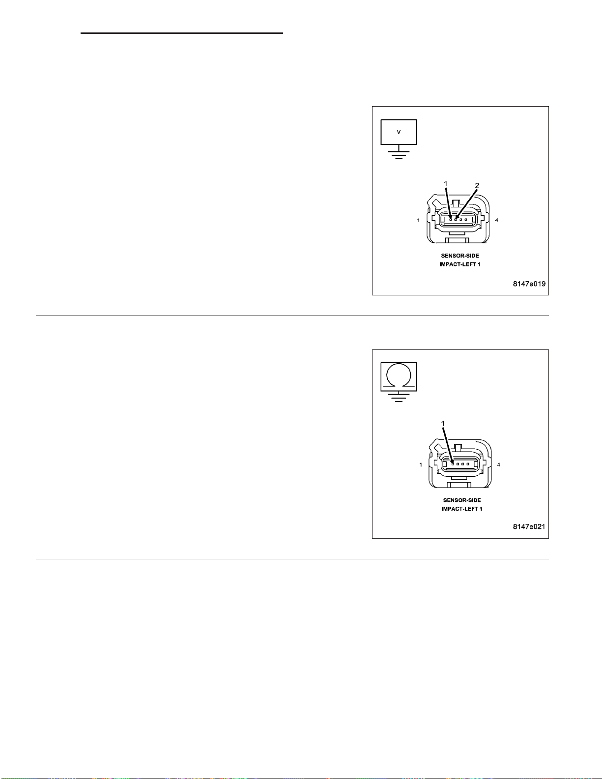
DR/DH RESTRAINTS - ELECTRICAL DIAGNOSTICS 8O - 95
LEFT SIDE IMPACT SENSOR 1 INTERNAL 1 (CONTINUED)
CHECK THE (R13, R15) LEFT SIDE IMPACT SENSOR 1 SIGNAL AND GROUND CIRCUITS FOR A SHORT
2.
TO BATTERY
WARNING: To avoid personal injury or death, turn the ignition off,
disconnect the battery and wait two minutes before proceeding.
Disconnect the Left side Impact Sensor 1 connector.
Disconnect the ORC connector.
WARNING: To avoid personal injury or death, turn the ignition on,
then reconnect the battery.
Measure the voltage of the (R13) Left Side Impact Sensor 1 Signal
circuit and (R15) Left Side Impact Sensor 1 Ground circuit at the Left
Side Impact Sensor 1 connector and ground.
Is there any voltage present?
Yes >>
No >>
CHECK THE (R13) LEFT SIDE IMPACT SENSOR 1 SIGNAL CIRCUIT FOR A SHORT TO GROUND
3.
WARNING: To avoid personal injury or death, turn ignition on,
then reconnect the battery.
Measure the resistance of the (R13) Left Side Impact Sensor 1 Signal
circuit between the Left Side Impact Sensor 1 connector and ground.
Is the resistance below 100K ohms?
Yes >>
No >>
Repair the (R13, R15) Left Side Impact Sensor 1 circuits
for a short to battery.
Perform the ORC VERIFICATION TEST - VER 1.
Go To 3
Repair the (R13) Left Side Impact Sensor 1 Signal circuit
for a short to ground.
Perform the ORC VERIFICATION TEST - VER 1.
Go To 4

8O - 96 RESTRAINTS - ELECTRICAL DIAGNOSTICS DR/DH
LEFT SIDE IMPACT SENSOR 1 INTERNAL 1 (CONTINUED)
CHECK THE (R13, R15) LEFT SIDE IMPACT SENSOR CIRCUITS FOR A SHORT TOGETHER
4.
Measure the resistance between the (R13) Left Side Impact Sensor 1
Signal circuit and (R15) Left Side Impact Sensor 1 Ground circuit at
the Left Side Impact Sensor 1 connector.
Is the resistance below 100K ohms?
Yes >>
No >>
CHECK THE (R15) LEFT SIDE IMPACT SENSOR 1 GROUND CIRCUIT FOR AN OPEN OR HIGH
5.
RESISTANCE
Connect the 8443 Load Tool ORC Adaptor to the Occupant Control
Module connector.
Measure the resistance of the (R15) Left Side Impact Sensor 1
Ground circuit between the Left Side Impact Sensor 1 connector and
the 8443 Load Tool ORC Adaptor.
Is the resistance below 1 ohm?
Yes >>
No >>
Repair the (R13, R15) Left Side Impact Sensor 1 circuits
shorted together.
Perform the ORC VERIFICATION TEST - VER 1.
Go To 5
Go To 6
Repair the (R15) Left Side Impact Sensor 1 Ground circuit
for an open or high resistance.
Perform the ORC VERIFICATION TEST - VER 1.

DR/DH RESTRAINTS - ELECTRICAL DIAGNOSTICS 8O - 97
LEFT SIDE IMPACT SENSOR 1 INTERNAL 1 (CONTINUED)
CHECK THE (R13) LEFT SIDE IMPACT SENSOR 1 CIRCUIT FOR AN OPEN OR HIGH RESISTANCE
6.
Measure the resistance of the (R13) Left Side Impact Sensor 1 Signal
circuit between the Left Side Impact Sensor 1 connector and the 8443
Load Tool ORC Adaptor.
Is the resistance below 1 ohm?
Yes >>
No >>
CHECK OPERATION OF THE LEFT SIDE IMPACT SENSOR 1
7.
Replace the Left Side Impact Sensor 1.
Reconnect the vehicle body harness to the impact sensor.
Remove any special tools or jumper wires and reconnect all previously disconnected components - except the Bat-
tery.
WARNING: To avoid personal injury or death, turn the ignition on, then reconnect the battery.
Connect the scan tool to the Data Link Connector - use the most current software available.
Use the scan tool and erase the stored codes in all airbag system modules.
Turn the Ignition Off, and wait 15 seconds before turning the Ignition On.
Wait one minute, and read active codes and if there are none present read the stored codes.
Go To 7
Repair the (R13) Left Side Impact Sensor 1 Signal circuit
for an open or high resistance.
Perform the ORC VERIFICATION TEST - VER 1.
Did DTC reset and is it active?
Yes >>
No >>
Go To 8
Repair is complete.
Perform the ORC VERIFICATION TEST - VER 1.

8O - 98 RESTRAINTS - ELECTRICAL DIAGNOSTICS DR/DH
LEFT SIDE IMPACT SENSOR 1 INTERNAL 1 (CONTINUED)
REPLACE THE OCCUPANT RESTRAINT CONTROLLER
8.
WARNING: To avoid personal injury or death, turn the ignition off, disconnect the battery and wait two minutes before proceeding.
WARNING: If the occupant restraint controller is dropped at any time, it must be replaced. Failure to take
the proper precautions could result in accidental airbag deployment and personal injury or death.
If there are no possible causes remaining, view repair.
Repair
Replace the Occupant Restraint Controller in accordance with Service Instructions.
Perform the ORC VERIFICATION TEST - VER 1.
TEST FOR AN INTERMITTENT CONDITION
9.
With the scan tool, record and erase all DTC’s from all Airbag modules.
If any ACTIVE codes are present they must be resolved before diagnosing any stored codes.
WARNING: To avoid personal injury or death, turn the ignition off, disconnect the battery and wait two minutes before proceeding.
Using the wiring diagram/schematic as a guide, inspect the wiring and connectors.
Look for chaffed, pierced, pinched, or partially broken wires and broken, bent, pushed out, spread, corroded, or
contaminated terminals.
The following additional checks may assist you in identifying a possible intermittent problem.
Reconnect any disconnected components and harness connector.
WARNING: To avoid personal injury or death, turn the ignition on, then reconnect the battery.
With the scan tool monitor active codes as you work through the following steps.
WARNING: To avoid personal injury or death, maintain a safe distance from all airbags while performing the
following steps.
Wiggle the wiring harness and connectors of the related airbag circuit or component.
If codes are related to the Driver Airbag circuits, rotate the steering wheel from stop to stop.
If only stored codes return continue the test until the problem area has been isolated.
In the previous steps you have attempted to recreate the conditions responsible for setting active DTC in question.
Are any ACTIVE DTCs present?
Yes >>
No >>
Select the appropriate symptom from Symptom List.
No problem found at this time. Erase all codes before returning vehicle to customer.

DR/DH RESTRAINTS - ELECTRICAL DIAGNOSTICS 8O - 99
LOSS OF IGNITION RUN - START

8O - 100 RESTRAINTS - ELECTRICAL DIAGNOSTICS DR/DH
LOSS OF IGNITION RUN - START (CONTINUED)
For the Airbag System circuit diagram (Refer to 8 - ELECTRICAL/RESTRAINTS - SCHEMATICS AND DIAGRAMS).
For a complete wiring diagram Refer to Section 8W.
• When Monitored:
With the ignition in the Run-Start position the Occupant Restraint Controller (ORC) monitors the (F201) Fused
Ignition Switch Output (Run-Start) circuit for proper system voltage.
• Set Condition:
If the voltage on the (F201) Fused Ignition Switch Output (Run-Start) circuit drops below approximately 4.5
volts, the code will set.
Possible Causes
(F201) FUSED IGNITION SWITCH OUTPUT (RUN-START) SHORTED TO GROUND
(F201) FUSED IGNITION SWITCH OUTPUT (RUN-START) CIRCUIT OPEN
(F951) IGNITION SWITCH OUTPUT CIRCUIT OPEN
AIRBAG RUN-START CIRCUIT FUSE OPEN
PAB ON - OFF SWITCH SHORTED TO GROUND
ORC, FUSED IGNITION OUTPUT (RUN-START) CIRCUIT SHORTED TO GROUND
ORC, FUSED IGNITION OUTPUT (RUN-START) CIRCUIT OPEN
Diagnostic Test
DETERMINE ACTIVE OR STORED DTC
1.
Turn the ignition on.
NOTE: Ensure that the battery is fully charged.
NOTE: For the purpose of this test, the AECM and ACM modules will be referred to as an ORC.
NOTE: When reconnecting Airbag system components, the ignition must be turned off and the battery must
be disconnected.
Select ACTIVE or STORED DTC:
ORC - ACTIVE DTC
Go To 2
ORC - STORED DTC
Go To 10
CHECKING AIRBAG RUN-START CIRCUIT FUSE
2.
Turn the ignition off.
Remove and inspect the Airbag Run-Start circuit fuse.
NOTE: Check connectors - Clean and repair as necessary.
Is the fuse open?
Yes >>
No >>
Go To 3
Go To 7
 Loading...