

Page 1

DR RESTRAINTS 8O - 1
RESTRAINTS
TABLE OF CONTENTS
page page
RESTRAINTS
DESCRIPTION ..........................2
OPERATION ............................4
WARNING
WARNINGS - RESTRAINT SYSTEM ........5
DIAGNOSIS AND TESTING - SUPPLEMENTAL
RESTRAINT SYSTEM ...................6
STANDARD PROCEDURE
STANDARD PROCEDURE - HANDLING
NON-DEPLOYED SUPPLEMENTAL
RESTRAINTS .........................6
STANDARD PROCEDURE - SERVICE
AFTER A SUPPLEMENTAL RESTRAINT
DEPLOYMENT.........................7
STANDARD PROCEDURE - VERIFICATION
TEST ................................8
ACM COVER
REMOVAL .............................9
INSTALLATION ..........................9
AIRBAG CONTROL MODULE
DESCRIPTION .........................10
OPERATION ...........................10
REMOVAL .............................11
INSTALLATION .........................12
AUTOMATIC LOCKING RETRACTOR
DESCRIPTION .........................13
OPERATION ...........................14
CHILD RESTRAINT ANCHOR
DESCRIPTION .........................14
OPERATION ...........................16
REMOVAL .............................16
INSTALLATION .........................17
CLOCKSPRING
DESCRIPTION .........................18
OPERATION ...........................18
STANDARD PROCEDURE - CLOCKSPRING
CENTERING .........................19
REMOVAL .............................20
INSTALLATION .........................21
DRIVER AIRBAG
DESCRIPTION .........................22
OPERATION ...........................23
REMOVAL .............................23
INSTALLATION .........................24
FRONT CENTER SEAT BELT & RETRACTOR
REMOVAL .............................25
INSTALLATION .........................26
FRONT CENTER SEAT BELT
REMOVAL .............................26
INSTALLATION .........................27
FRONT OUTBOARD SEAT BELT &
RETRACTOR
REMOVAL
REMOVAL - STANDARD CAB ............28
REMOVAL - QUAD CAB ................29
INSTALLATION
INSTALLATION - STANDARD CAB .........31
INSTALLATION - QUAD CAB .............32
FRONT OUTBOARD SEAT BELT BUCKLE
REMOVAL .............................33
INSTALLATION .........................34
PASSENGER AIRBAG
DESCRIPTION .........................34
OPERATION ...........................35
REMOVAL .............................35
INSTALLATION .........................37
PASSENGER AIRBAG ON/OFF SWITCH
DESCRIPTION .........................38
OPERATION ...........................38
REMOVAL .............................39
INSTALLATION .........................39
REAR CENTER SEAT BELT & RETRACTOR
REMOVAL .............................39
INSTALLATION .........................40
REAR OUTBOARD SEAT BELT & RETRACTOR
REMOVAL .............................41
INSTALLATION .........................42
REAR SEAT BELT BUCKLE
REMOVAL
REMOVAL - CENTER & LEFT OUTBOARD . . 43
REMOVAL - CENTER ANCHOR & RIGHT
OUTBOARD..........................43
INSTALLATION
INSTALLATION - CENTER & LEFT
OUTBOARD..........................45
INSTALLATION - CENTER ANCHOR &
RIGHT OUTBOARD ....................45
SEAT BELT SWITCH
DESCRIPTION .........................46
OPERATION ...........................46
DIAGNOSIS AND TESTING - SEAT BELT
SWITCH ............................47
SEAT BELT TENSIONER
DESCRIPTION .........................47
OPERATION ...........................48
SEAT BELT TENSION REDUCER
DESCRIPTION .........................48
OPERATION ...........................49
Page 2

8O - 2 RESTRAINTS DR
DIAGNOSIS AND TESTING - SEAT BELT
TENSION REDUCER ...................49
SEAT BELT TURNING LOOP ADJUSTER
REMOVAL .............................50
INSTALLATION .........................50
SIDE CURTAIN AIRBAG
DESCRIPTION .........................51
OPERATION ...........................51
REMOVAL .............................52
INSTALLATION .........................53
RESTRAINTS
DESCRIPTION
An occupant restraint system is standard factoryinstalled safety equipment on this model. Available
occupant restraints for this model include both active
and passive types. Active restraints are those which
require the vehicle occupants to take some action to
employ, such as fastening a seat belt; while passive
restraints require no action by the vehicle occupants
to be employed (Fig. 1).
ACTIVE RESTRAINTS
The active restraints for this model include:
• Front Seat Belts - Both outboard front seating
positions are equipped with three-point seat belt systems employing a lower B-pillar mounted inertia
latch-type emergency locking retractor, height-adjustable upper B-pillar mounted turning loops, a fixed
lower seat belt anchor secured to the lower B-pillar
(standard cab) or floor panel adjacent to the B-pillar
(quad cab), and a traveling end-release seat belt
buckle secured to the inboard seat track. The driver
side retractor for standard cab models includes an
electrically actuated seat belt tension reducer. The
passenger side front seat retractor for all models is
also switchable from an emergency locking retractor
to an automatic locking retractor. The front seat belt
buckle for the driver side of all models includes an
integral seat belt switch that detects whether its seat
belt has been fastened. The center front seating position for standard cab models is also equipped with a
three-point seat belt employing a floor panel
mounted inertia latch-type retractor, a routing
bracket and bezel near the top of the cab back panel,
and two fixed end-release buckles secured to the center seat cushion frame. The center front seating position for quad cab models is equipped with a fixed lap
belt and an end-release buckle secured to the center
seat cushion frame.
• Rear Seat Belts - All three rear seating posi-
tions are equipped with three-point seat belt systems. The outboard seating position belts employ a
lower C-pillar mounted inertia latch-type emergency
locking retractor, a fixed position upper C-pillar
mounted turning loop, and a fixed lower seat belt
SIDE IMPACT AIRBAG CONTROL MODULE
DESCRIPTION .........................53
OPERATION ...........................54
REMOVAL
REMOVAL ...........................55
REMOVAL ...........................55
INSTALLATION
INSTALLATION .......................56
INSTALLATION .......................57
anchor secured to the lower C-pillar. The rear seat
center seating position belt has a rear floor panel
mounted inertia latch-type emergency locking retractor and a routing bracket and bezel on the top of the
cab back panel. The end-release buckle units for the
right outboard seating position and the center seating position lower anchor are integral to the center
retractor mounting bracket on the rear floor panel.
The end-release buckle units for the center and left
outboard seating positions are individually secured to
the rear floor panel on models with the standard
equipment rear bench seat, or secured with the rear
seat mounting hardware on models with the optional
60/40 split rear bench seat.
• Child Restraint Anchors - All standard cab
models are equipped with two, fixed-position, child
seat upper tether anchors that are integral to the
upper cab back panel reinforcement and concealed
behind individual trim cover and bezel units that are
integral to the cab back trim panel. All quad cab
models are equipped with three child seat upper
tether anchor straps that are secured to the upper
cab back panel reinforcement, behind the upright
rear seat back. Two lower anchors are also provided
for the front outboard seating position of standard
cab models, and for each rear outboard seating position on quad cab models. These lower anchors are
accessed from the front of the seat where the seat
back meets the seat cushion. The child seat tether
and lower anchors for the front seat are deleted on
quad cab models.
PASSIVE RESTRAINTS
The passive restraints available for this model
include the following:
• Dual Front Airbags - Next Generation driver
and front passenger airbags are available for this
model. This airbag system is a passive, inflatable,
Supplemental Restraint System (SRS) and vehicles
with this equipment can be readily identified by the
“SRS - AIRBAG” logo molded into the driver airbag
trim cover in the center of the steering wheel and
also into the passenger airbag door on the instrument panel above the glove box (Fig. 2). Vehicles
with the airbag system can also be identified by the
airbag indicator, which will illuminate in the instru-
Page 3
DR RESTRAINTS 8O - 3
RESTRAINTS (Continued)
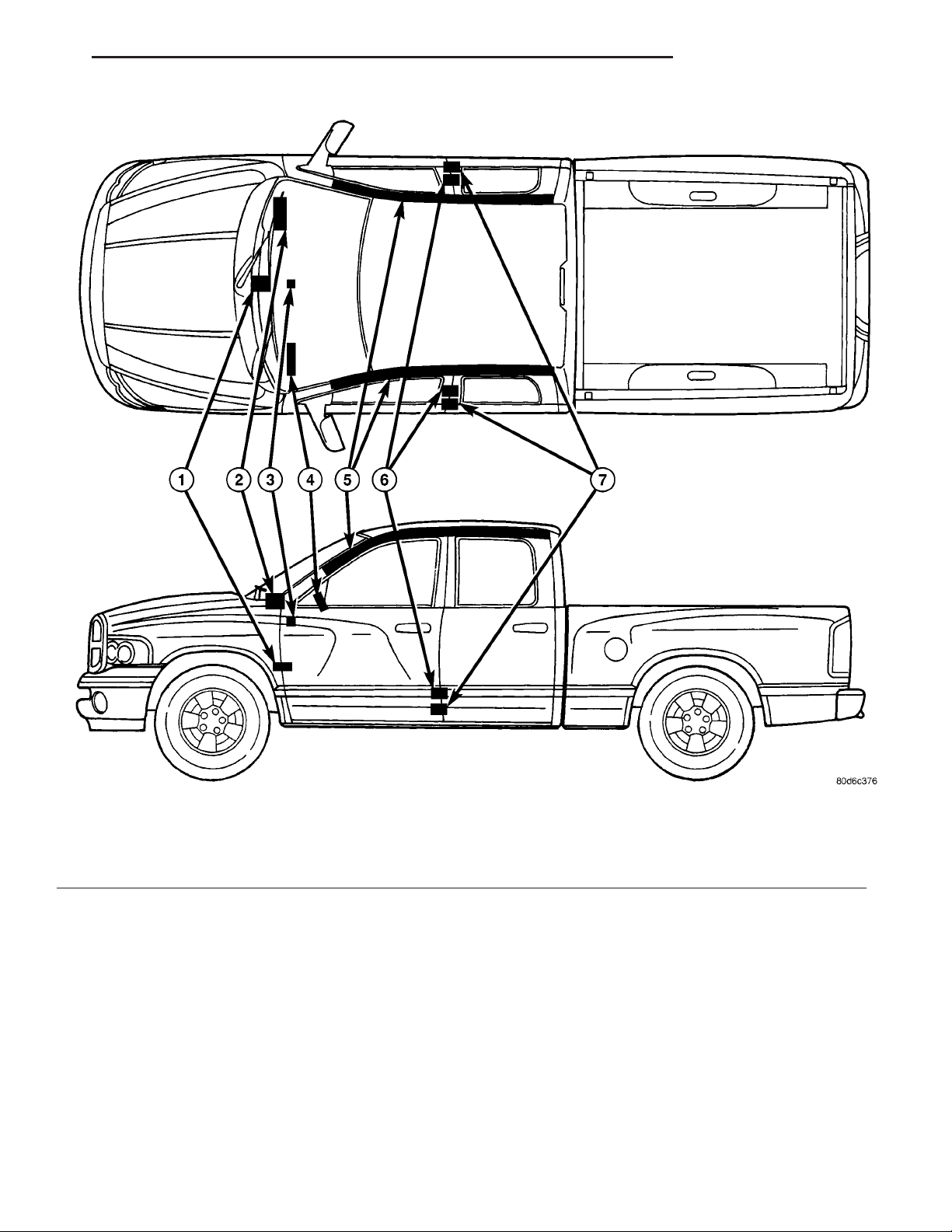
Fig. 1 Supplemental Restraint System
1 - AIRBAG CONTROL MODULE
2 - PASSENGER AIRBAG
3 - PASSENGER AIRBAG ON/OFF SWITCH (STD CAB ONLY)
4 - DRIVERAIRBAG
ment cluster for about six seconds as a bulb test each
time the ignition switch is turned to the On position.
A pyrotechnic-type seat belt tensioner is integral to
the front outboard seat belt retractors mounted on
each lower B-pillar of all models equipped with dual
front airbags.
• Side Curtain Airbags - Optional side curtain
airbags are available for this model when it is also
equipped with dual front airbags. This airbag system
is a passive, inflatable, Supplemental Restraint System (SRS) and vehicles with this equipment can be
readily identified by a molded identification trim but-
5 - SIDE CURTAIN AIRBAG
6 - SIDE IMPACT AIRBAG CONTROL MODULE
7 - SEAT BELT TENSIONER
ton with the “SRS - AIRBAG” logo located on the
headliner above each B-pillar (Fig. 2).
The supplemental restraint system includes the
following major components, which are described in
further detail elsewhere in this service information:
• Airbag Control Module - The Airbag Control
Module (ACM) is located on a mount on the floor
panel transmission tunnel, below the center of the
instrument panel.
• Airbag Indicator - The airbag indicator is inte-
gral to the ElectroMechanical Instrument Cluster
(EMIC), which is located on the instrument panel in
front of the driver.
Page 4
8O - 4 RESTRAINTS DR
RESTRAINTS (Continued)
the Programmable Communications Interface (PCI)
data bus network. This method of communication is
used by the ACM for control of the airbag indicator
on all models equipped with dual front airbags.
(Refer to 8 - ELECTRICAL/ELECTRONIC CONTROL MODULES/COMMUNICATION - DESCRIPTION).
Hard wired circuitry connects the supplemental
restraint system components to each other through
the electrical system of the vehicle. These hard wired
circuits are integral to several wire harnesses, which
are routed throughout the vehicle and retained by
many different methods. These circuits may be connected to each other, to the vehicle electrical system,
and to the supplemental restraint system components through the use of a combination of soldered
Fig. 2 SRS Logo
• Clockspring - The clockspring is located near
the top of the steering column, directly beneath the
steering wheel.
• Driver Airbag - The driver airbag is located in
the center of the steering wheel, beneath the driver
airbag trim cover.
• Driver Knee Blocker - The driver knee blocker
is a structural unit secured to the back side of and
integral to the instrument panel steering column
opening cover.
• Passenger Airbag - The passenger airbag is
located on the instrument panel, beneath the passenger airbag door on the instrument panel above the
glove box on the passenger side of the vehicle.
• Passenger Airbag On/Off Switch - Standard
cab models without a rear seat are equipped with a
passenger airbag on/off switch, which is located on
the right side of the instrument panel center bezel.
• Passenger Knee Blocker - The passenger knee
blocker is a structural reinforcement that is integral
to and concealed within the glove box door.
• Seat Belt Tensioner - The seat belt tensioner
is integral to the front outboard seat belt retractor
units on vehicles equipped with dual front airbags.
• Side Impact Airbag Control Module -Two
Side Impact Airbag Control Modules (SIACM) are
used on vehicles with the optional side curtain airbags, one left side and one right side. One SIACM is
located behind the B-pillar trim above the outboard
front seat belt retractor within each B-pillar.
• Side Curtain Airbag - In vehicles equipped
with this option, a side curtain airbag is located on
each inside roof side rail above the headliner, and
extends from the A-pillar to the B-pillar on standard
cab models, and from the A-pillar to the C-pillar on
quad cab models.
The ACM, both SIACMs, and the EMIC each contain a central processing unit and programming that
allow them to communicate with each other using
splices, splice block connectors, and many different
types of wire harness terminal connectors and insulators. Refer to the appropriate wiring information.
The wiring information includes wiring diagrams,
proper wire and connector repair procedures, further
details on wire harness routing and retention, as well
as pin-out and location views for the various wire
harness connectors, splices and grounds.
OPERATION
ACTIVE RESTRAINTS
The primary passenger restraints in this or any
other vehicle are the standard equipment factory-installed seat belts and child restraint anchors. Seat
belts and child restraint anchors are referred to as
an active restraint because the vehicle occupants are
required to physically fasten and properly adjust
these restraints in order to benefit from them. See
the owner’s manual in the vehicle glove box for more
information on the features, use and operation of all
of the factory-installed active restraints.
PASSIVE RESTRAINTS
The passive restraints are referred to as a supplemental restraint system because they were designed
and are intended to enhance the protection for the
occupants of the vehicle only when used in conjunction with the seat belts. They are referred to as passive restraints because the vehicle occupants are not
required to do anything to make them operate; however, the vehicle occupants must be wearing their
seat belts in order to obtain the maximum safety
benefit from the factory-installed supplemental
restraint system.
The supplemental restraint system electrical circuits are continuously monitored and controlled by a
microprocessor and software contained within the
Airbag Control Module (ACM) and, on vehicles
equipped with the side curtain airbags, both Side
Page 5

DR RESTRAINTS 8O - 5
RESTRAINTS (Continued)
Impact Airbag Control Modules (SIACM). An airbag
indicator in the ElectroMechanical Instrument Cluster (EMIC) illuminates for about six seconds as a
bulb test each time the ignition switch is turned to
the On or Start positions. Following the bulb test,
the airbag indicator is turned on or off by the ACM
to indicate the status of the supplemental restraint
system. If the airbag indicator comes on at any time
other than during the bulb test, it indicates that
there is a problem in the supplemental restraint system electrical circuits. Such a problem may cause airbags not to deploy when required, or to deploy when
not required.
Deployment of the supplemental restraints
depends upon the angle and severity of an impact.
Deployment is not based upon vehicle speed; rather,
deployment is based upon the rate of deceleration as
measured by the forces of gravity (G force) upon the
impact sensors. When an impact is severe enough,
the microprocessor in the ACM or the SIACM signals
the inflator of the appropriate airbag units to deploy
their airbag cushions. The outboard front seat belt
tensioners are provided with a deployment signal by
the ACM in conjunction with the driver and passenger airbags. During a frontal vehicle impact, the
knee blockers work in concert with properly fastened
and adjusted seat belts to restrain both the driver
and the front seat passenger in the proper position
for an airbag deployment. The knee blockers also
absorb and distribute the crash energy from the
driver and the front seat passenger to the structure
of the instrument panel. The seat belt tensioner
removes the slack from the outboard front seat belts
to provide further assurance that the driver and
front seat passenger are properly positioned and
restrained for an airbag deployment.
Typically, the vehicle occupants recall more about
the events preceding and following a collision than
they do of an airbag deployment itself. This is
because the airbag deployment and deflation occur so
rapidly. In a typical 48 kilometer-per-hour (30 mileper-hour) barrier impact, from the moment of impact
until the airbags are fully inflated takes about 40
milliseconds. Within one to two seconds from the
moment of impact, the airbags are almost entirely
deflated. The times cited for these events are approximations, which apply only to a barrier impact at the
given speed. Actual times will vary somewhat,
depending upon the vehicle speed, impact angle,
severity of the impact, and the type of collision.
When the ACM monitors a problem in any of the
dual front airbag system circuits or components,
including the seat belt tensioners, it stores a fault
code or Diagnostic Trouble Code (DTC) in its memory
circuit and sends an electronic message to the EMIC
to turn on the airbag indicator. When the SIACM
monitors a problem in any of the side curtain airbag
system circuits or component, it stores a fault code or
DTC in its memory circuit and sends an electronic
message to the ACM, and the ACM sends an electronic message to the EMIC to turn on the airbag
indicator. Proper testing of the supplemental
restraint system components, the Programmable
Communications Interface (PCI) data bus, the electronic message inputs to and outputs from the EMIC,
the SIACM, or the ACM, as well as the retrieval or
erasure of a DTC from the ACM, SIACM, or EMIC
requires the use of a DRBIIIt scan tool. Refer to the
appropriate diagnostic information.
See the owner’s manual in the vehicle glove box for
more information on the features, use and operation
of all of the factory-installed passive restraints.
WARNING
WARNINGS - RESTRAINT SYSTEM
WARNING: DURING AND FOLLOWING ANY SEAT
BELT OR CHILD RESTRAINT ANCHOR SERVICE,
CAREFULLY INSPECT ALL SEAT BELTS, BUCKLES,
MOUNTING HARDWARE, RETRACTORS, TETHER
STRAPS, AND ANCHORS FOR PROPER INSTALLATION, OPERATION, OR DAMAGE. REPLACE ANY
BELT THAT IS CUT, FRAYED, OR TORN.
STRAIGHTEN ANY BELT THAT IS TWISTED.
TIGHTEN ANY LOOSE FASTENERS. REPLACE ANY
BELT THAT HAS A DAMAGED OR INOPERATIVE
BUCKLE OR RETRACTOR. REPLACE ANY BELT
THAT HAS A BENT OR DAMAGED LATCH PLATE
OR ANCHOR PLATE. REPLACE ANY CHILD
RESTRAINT ANCHOR OR THE UNIT TO WHICH THE
ANCHOR IS INTEGRAL THAT HAS BEEN BENT OR
DAMAGED. NEVER ATTEMPT TO REPAIR A SEAT
BELT OR CHILD RESTRAINT COMPONENT.
ALWAYS REPLACE DAMAGED OR FAULTY SEAT
BELT AND CHILD RESTRAINT COMPONENTS WITH
THE CORRECT, NEW AND UNUSED REPLACEMENT
PARTS LISTED IN THE DAIMLERCHRYSLER MOPAR
PARTS CATALOG.
Page 6

8O - 6 RESTRAINTS DR
RESTRAINTS (Continued)
WARNING: ON VEHICLES EQUIPPED WITH AIRBAGS, DISABLE THE SUPPLEMENTAL RESTRAINT
SYSTEM BEFORE ATTEMPTING ANY STEERING
WHEEL, STEERING COLUMN, DRIVER AIRBAG,
PASSENGER AIRBAG, SEAT BELT TENSIONER,
SIDE CURTAIN AIRBAG, OR INSTRUMENT PANEL
COMPONENT DIAGNOSIS OR SERVICE. DISCONNECT AND ISOLATE THE BATTERY NEGATIVE
(GROUND) CABLE, THEN WAIT TWO MINUTES FOR
THE SYSTEM CAPACITOR TO DISCHARGE BEFORE
PERFORMING FURTHER DIAGNOSIS OR SERVICE.
THIS IS THE ONLY SURE WAY TO DISABLE THE
SUPPLEMENTAL RESTRAINT SYSTEM. FAILURE TO
TAKE THE PROPER PRECAUTIONS COULD
RESULT IN ACCIDENTAL AIRBAG DEPLOYMENT
AND POSSIBLE PERSONAL INJURY.
WARNING: AN AIRBAG INFLATOR UNIT MAY CONTAIN SODIUM AZIDE AND POTASSIUM NITRATE.
THESE MATERIALS ARE POISONOUS AND
EXTREMELY FLAMMABLE. CONTACT WITH ACID,
WATER, OR HEAVY METALS MAY PRODUCE HARMFUL AND IRRITATING GASES (SODIUM HYDROXIDE
IS FORMED IN THE PRESENCE OF MOISTURE) OR
COMBUSTIBLE COMPOUNDS. AN AIRBAG INFLATOR UNIT MAY ALSO CONTAIN A GAS CANISTER
PRESSURIZED TO OVER 2500 PSI. DO NOT
ATTEMPT TO DISMANTLE AN AIRBAG UNIT OR
TAMPER WITH ITS INFLATOR. DO NOT PUNCTURE,
INCINERATE, OR BRING INTO CONTACT WITH
ELECTRICITY. DO NOT STORE AT TEMPERATURES
EXCEEDING 93° C (200° F).
WARNING: WHEN HANDLING A SEAT BELT TENSIONER RETRACTOR, PROPER CARE SHOULD BE
EXERCISED TO KEEP FINGERS OUT FROM UNDER
THE RETRACTOR COVER AND AWAY FROM THE
SEAT BELT WEBBING WHERE IT EXITS FROM THE
RETRACTOR COVER.
THE CORRECT FASTENERS PROVIDED IN THE
SERVICE PACKAGE OR SPECIFIED IN THE
DAIMLERCHRYSLER MOPAR PARTS CATALOG.
WARNING: WHEN A STEERING COLUMN HAS AN
AIRBAG UNIT ATTACHED, NEVER PLACE THE COLUMN ON THE FLOOR OR ANY OTHER SURFACE
WITH THE STEERING WHEEL OR AIRBAG UNIT
FACE DOWN.
DIAGNOSIS AND TESTING - SUPPLEMENTAL
RESTRAINT SYSTEM
Proper diagnosis and testing of the supplemental
restraint system components, the Programmable
Communications Interface (PCI) data bus, the data
bus electronic message inputs to and outputs from
the ElectroMechanical Instrument Cluster (EMIC),
the Airbag Control Module (ACM), or the Side
Impact Airbag Control Module (SIACM) as well as
the retrieval or erasure of a Diagnostic Trouble Code
(DTC) from the ACM or SIACM requires the use of a
DRBIIIt scan tool. Refer to the appropriate diagnostic information.
WARNING: ON VEHICLES EQUIPPED WITH AIRBAGS, DISABLE THE SUPPLEMENTAL RESTRAINT
SYSTEM BEFORE ATTEMPTING ANY STEERING
WHEEL, STEERING COLUMN, DRIVER AIRBAG,
PASSENGER AIRBAG, SEAT BELT TENSIONER,
SIDE CURTAIN AIRBAG, OR INSTRUMENT PANEL
COMPONENT DIAGNOSIS OR SERVICE. DISCONNECT AND ISOLATE THE BATTERY NEGATIVE
(GROUND) CABLE, THEN WAIT TWO MINUTES FOR
THE SYSTEM CAPACITOR TO DISCHARGE BEFORE
PERFORMING FURTHER DIAGNOSIS OR SERVICE.
THIS IS THE ONLY SURE WAY TO DISABLE THE
SUPPLEMENTAL RESTRAINT SYSTEM. FAILURE TO
TAKE THE PROPER PRECAUTIONS COULD
RESULT IN ACCIDENTAL AIRBAG DEPLOYMENT
AND POSSIBLE PERSONAL INJURY.
WARNING: REPLACE ALL RESTRAINT SYSTEM
COMPONENTS ONLY WITH PARTS SPECIFIED IN
THE DAIMLERCHRYSLER MOPAR PARTS CATALOG. SUBSTITUTE PARTS MAY APPEAR INTERCHANGEABLE, BUT INTERNAL DIFFERENCES MAY
RESULT IN INFERIOR OCCUPANT PROTECTION.
WARNING: THE FASTENERS, SCREWS, AND
BOLTS ORIGINALLY USED FOR THE RESTRAINT
SYSTEM COMPONENTS HAVE SPECIAL COATINGS
AND ARE SPECIFICALLY DESIGNED FOR THE
RESTRAINT SYSTEM. THEY MUST NEVER BE
REPLACED WITH ANY SUBSTITUTES. ANY TIME A
NEW FASTENER IS NEEDED, REPLACE IT WITH
STANDARD PROCEDURE
STANDARD PROCEDURE - HANDLING
NON-DEPLOYED SUPPLEMENTAL RESTRAINTS
At no time should any source of electricity be permitted near the inflator on the back of a non-deployed airbag or seat belt tensioner. When carrying a
non-deployed airbag, the trim cover or airbag cushion
side of the unit should be pointed away from the
body to minimize injury in the event of an accidental
deployment. If the airbag unit is placed on a bench or
any other surface, the trim cover or airbag cushion
side of the unit should be face up to minimize move-
Page 7

DR RESTRAINTS 8O - 7
RESTRAINTS (Continued)
ment in the event of an accidental deployment. When
handling a non-deployed seat belt tensioner, take
proper care to keep fingers out from under the
retractor cover and away from the seat belt webbing
where it exits from the retractor cover. In addition,
the supplemental restraint system should be disarmed whenever any steering wheel, steering column, seat belt tensioner, driver airbag, passenger
airbag, side curtain airbag, or instrument panel components require diagnosis or service. Failure to
observe this warning could result in accidental airbag deployment and possible personal injury.
All damaged, faulty or non-deployed airbags and
seat belt tensioners which are replaced on vehicles
are to be handled and disposed of properly. If an airbag or seat belt tensioner unit is faulty or damaged
and non-deployed, refer to the Hazardous Substance
Control System for proper disposal. Dispose of all
non-deployed and deployed airbags and seat belt tensioners in a manner consistent with state, provincial,
local and federal regulations.
SUPPLEMENTAL RESTRAINT STORAGE
Airbags and seat belt tensioners must be stored in
their original, special container until they are used
for service. Also, they must be stored in a clean, dry
environment; away from sources of extreme heat,
sparks, and high electrical energy. Always place or
store any airbag on a surface with its trim cover or
airbag cushion side facing up, to minimize movement
in case of an accidental deployment.
age. Because the ACM and SIACM each contain
impact sensors that are used by the supplemental
restraint system to monitor or confirm the direction
and severity of a vehicle impact, improper orientation
or insecure fastening of these components may cause
airbags not to deploy when required, or to deploy
when not required. All other vehicle components
should be closely inspected following any supplemental restraint deployment, but are to be replaced only
as required by the extent of the visible damage
incurred.
CLEANUP PROCEDURE
Following a supplemental restraint deployment,
the vehicle interior will contain a powdery residue.
This residue consists primarily of harmless particulate by-products of the small pyrotechnic charge that
initiates the propellant used to deploy a supplemental restraint. However, this residue may also contain
traces of sodium hydroxide powder, a chemical
by-product of the propellant material that is used to
generate the inert gas that inflates the airbag. Since
sodium hydroxide powder can irritate the skin, eyes,
nose, or throat, be certain to wear safety glasses,
rubber gloves, and a long-sleeved shirt during
cleanup (Fig. 3).
STANDARD PROCEDURE - SERVICE AFTER A
SUPPLEMENTAL RESTRAINT DEPLOYMENT
Any vehicle which is to be returned to use following a supplemental restraint deployment, must have
the deployed restraints replaced. In addition, if the
driver airbag has been deployed, the clockspring
must be replaced. If the passenger airbag is
deployed, the passenger airbag door must be
replaced. The seat belt tensioners are deployed by
the same signal that deploys the driver and passenger airbags and must also be replaced if either front
airbag has been deployed. If a side curtain airbag
has been deployed, the complete airbag unit, the
headliner, as well as the upper A, B, and C-pillar
trim must be replaced. These components are not
intended for reuse and will be damaged or weakened
as a result of a supplemental restraint deployment,
which may or may not be obvious during a visual
inspection.
It is also critical that the mounting surfaces and/or
mounting brackets for the Airbag Control Module
(ACM) and Side Impact Airbag Control Module
(SIACM) be closely inspected and restored to their
original conditions following any vehicle impact dam-
Fig. 3 Wear Safety Glasses and Rubber Gloves -
Typical
WARNING: IF YOU EXPERIENCE SKIN IRRITATION
DURING CLEANUP, RUN COOL WATER OVER THE
AFFECTED AREA. ALSO, IF YOU EXPERIENCE
IRRITATION OF THE NOSE OR THROAT, EXIT THE
VEHICLE FOR FRESH AIR UNTIL THE IRRITATION
CEASES. IF IRRITATION CONTINUES, SEE A PHYSICIAN.
(1) Begin the cleanup by using a vacuum cleaner
to remove any residual powder from the vehicle interior. Clean from outside the vehicle and work your
Page 8
8O - 8 RESTRAINTS DR
RESTRAINTS (Continued)
way inside, so that you avoid kneeling or sitting on a
non-cleaned area.
(2) Be certain to vacuum the heater and air conditioning outlets as well (Fig. 4). Run the heater and
air conditioner blower on the lowest speed setting
and vacuum any powder expelled from the outlets.
Fig. 4 Vacuum Heater and A/C Outlets - Typical
CAUTION: All damaged, faulty, or non-deployed
supplemental restraints which are replaced on vehicles are to be handled and disposed of properly. If
an airbag unit or seat belt tensioner unit is faulty or
damaged and non-deployed, refer to the Hazardous
Substance Control System for proper disposal. Be
certain to dispose of all non-deployed and deployed
supplemental restraints in a manner consistent with
state, provincial, local and federal regulations.
PERFORMING FURTHER DIAGNOSIS OR SERVICE.
THIS IS THE ONLY SURE WAY TO DISABLE THE
SUPPLEMENTAL RESTRAINT SYSTEM. FAILURE TO
TAKE THE PROPER PRECAUTIONS COULD
RESULT IN ACCIDENTAL AIRBAG DEPLOYMENT
AND POSSIBLE PERSONAL INJURY.
(1) During the following test, the battery negative
cable remains disconnected and isolated, as it was
during the supplemental restraint system component
removal and installation procedures.
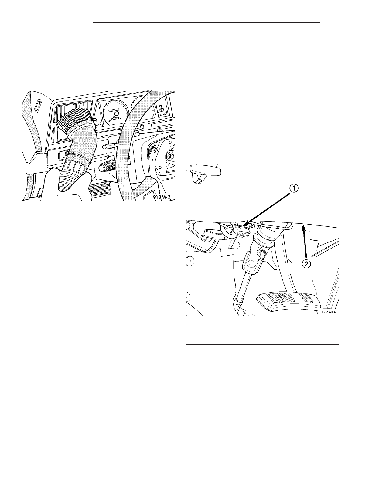
(2) Be certain that the DRBIIIt scan tool contains
the latest version of the proper DRBIIIt software.
Connect the DRBIIIt to the 16-way Data Link Connector (DLC). The DLC is located on the driver side
lower edge of the instrument panel, outboard of the
steering column (Fig. 5).
(3) Next, remove the deployed supplemental
restraints from the vehicle. Refer to the appropriate
service removal procedures.
(4) You may need to vacuum the interior of the
vehicle a second time to recover all of the powder.
STANDARD PROCEDURE - VERIFICATION TEST
The following procedure should be performed using
a DRBIIIt scan tool to verify proper supplemental
restraint system operation following the service or
replacement of any supplemental restraint system
component.
WARNING: ON VEHICLES EQUIPPED WITH AIRBAGS, DISABLE THE SUPPLEMENTAL RESTRAINT
SYSTEM BEFORE ATTEMPTING ANY STEERING
WHEEL, STEERING COLUMN, DRIVER AIRBAG,
PASSENGER AIRBAG, SEAT BELT TENSIONER,
SIDE CURTAIN AIRBAG, OR INSTRUMENT PANEL
COMPONENT DIAGNOSIS OR SERVICE. DISCONNECT AND ISOLATE THE BATTERY NEGATIVE
(GROUND) CABLE, THEN WAIT TWO MINUTES FOR
THE SYSTEM CAPACITOR TO DISCHARGE BEFORE
Fig. 5 16-Way Data Link Connector - Typical
1 - 16–WAY DATA LINK CONNECTOR
2 - BOTTOM OF INSTRUMENT PANEL
(3) Turn the ignition switch to the On position and
exit the vehicle with the DRBIIIt scan tool.
(4) Check to be certain that nobody is in the vehi-
cle, then reconnect the battery negative cable.
(5) Using the DRBIIIt, read and record the active
(current) Diagnostic Trouble Code (DTC) data.
(6) Next, use the DRBIIIt to read and record any
stored (historical) DTC data.
(7) If any DTC is found in Step 5 or Step 6, refer
to the appropriate diagnostic information.
(8) Use the DRBIIIt to erase the stored DTC data.
If any problems remain, the stored DTC data will not
erase. Refer to the appropriate diagnostic information to diagnose any stored DTC that will not erase.
Page 9
DR RESTRAINTS 8O - 9
RESTRAINTS (Continued)
If the stored DTC information is successfully erased,
go to Step 9.
(9) Turn the ignition switch to the Off position for
about fifteen seconds, and then back to the On position. Observe the airbag indicator in the instrument
cluster. It should illuminate for six to eight seconds,
and then go out. This indicates that the supplemental restraint system is functioning normally and that
the repairs are complete. If the airbag indicator fails
to light, or lights and stays on, there is still an active
supplemental restraint system fault or malfunction.
Refer to the appropriate diagnostic information to
diagnose the problem.
ACM COVER
Fig. 6 ACM Cover Remove/Install
REMOVAL
The Airbag Control Module (ACM) cover is used
only on models with an automatic transmission. Models with a manual transmission require that the floor
console be removed to access the ACM for service.
(Refer to 23 - BODY/INTERIOR/FLOOR CONSOLE REMOVAL).
WARNING: ON VEHICLES EQUIPPED WITH AIRBAGS, DISABLE THE SUPPLEMENTAL RESTRAINT
SYSTEM BEFORE ATTEMPTING ANY STEERING
WHEEL, STEERING COLUMN, DRIVER AIRBAG,
PASSENGER AIRBAG, SEAT BELT TENSIONER,
SIDE CURTAIN AIRBAG, OR INSTRUMENT PANEL
COMPONENT DIAGNOSIS OR SERVICE. DISCONNECT AND ISOLATE THE BATTERY NEGATIVE
(GROUND) CABLE, THEN WAIT TWO MINUTES FOR
THE SYSTEM CAPACITOR TO DISCHARGE BEFORE
PERFORMING FURTHER DIAGNOSIS OR SERVICE.
THIS IS THE ONLY SURE WAY TO DISABLE THE
SUPPLEMENTAL RESTRAINT SYSTEM. FAILURE TO
TAKE THE PROPER PRECAUTIONS COULD
RESULT IN ACCIDENTAL AIRBAG DEPLOYMENT
AND POSSIBLE PERSONAL INJURY.
(1) Disconnect and isolate the battery negative
cable. Wait two minutes for the system capacitor to
discharge before further service.
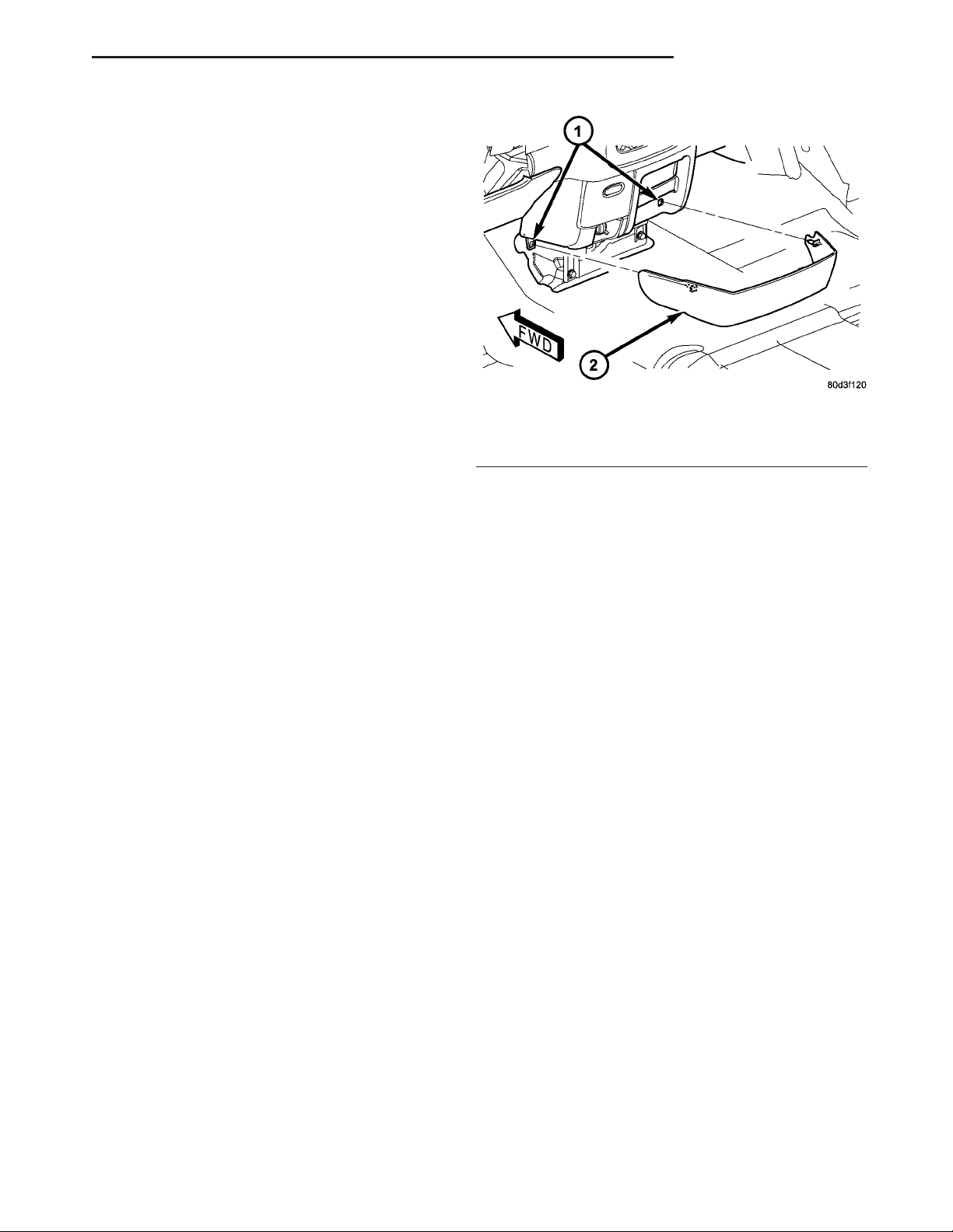
(2) Using a trim stick or another suitable wide
flat-bladed tool, gently pry each side of the ACM
cover away from the instrument panel at each side of
the center bracket on the floor panel transmission
tunnel far enough to disengage the two snap clip
retainers from the instrument panel receptacles (Fig.
6).
(3) Remove the ACM cover from the instrument
panel.
1 - INSTRUMENT PANEL RECEPTACLE (2)
2 - ACM COVER
INSTALLATION
The Airbag Control Module (ACM) cover is used
only on models with an automatic transmission. Models with a manual transmission require that the floor
console be reinstalled following ACM service. (Refer
to 23 - BODY/INTERIOR/FLOOR CONSOLE INSTALLATION).
WARNING: ON VEHICLES EQUIPPED WITH AIRBAGS, DISABLE THE SUPPLEMENTAL RESTRAINT
SYSTEM BEFORE ATTEMPTING ANY STEERING
WHEEL, STEERING COLUMN, DRIVER AIRBAG,
PASSENGER AIRBAG, SEAT BELT TENSIONER,
SIDE CURTAIN AIRBAG, OR INSTRUMENT PANEL
COMPONENT DIAGNOSIS OR SERVICE. DISCONNECT AND ISOLATE THE BATTERY NEGATIVE
(GROUND) CABLE, THEN WAIT TWO MINUTES FOR
THE SYSTEM CAPACITOR TO DISCHARGE BEFORE
PERFORMING FURTHER DIAGNOSIS OR SERVICE.
THIS IS THE ONLY SURE WAY TO DISABLE THE
SUPPLEMENTAL RESTRAINT SYSTEM. FAILURE TO
TAKE THE PROPER PRECAUTIONS COULD
RESULT IN ACCIDENTAL AIRBAG DEPLOYMENT
AND POSSIBLE PERSONAL INJURY.
(1) Position the ACM cover to the instrument
panel (Fig. 6).
(2) Align the snap clip retainer on each side of the
ACM cover with the instrument panel receptacle at
each side of the center bracket on the floor panel
transmission tunnel.
(3) Using hand pressure, press firmly and evenly
on the outside of the ACM cover over each snap clip
retainer location until each retainer is fully engaged
in its instrument panel receptacle.
(4) Reconnect the battery negative cable.
Page 10
8O - 10 RESTRAINTS DR
AIRBAG CONTROL MODULE
DESCRIPTION
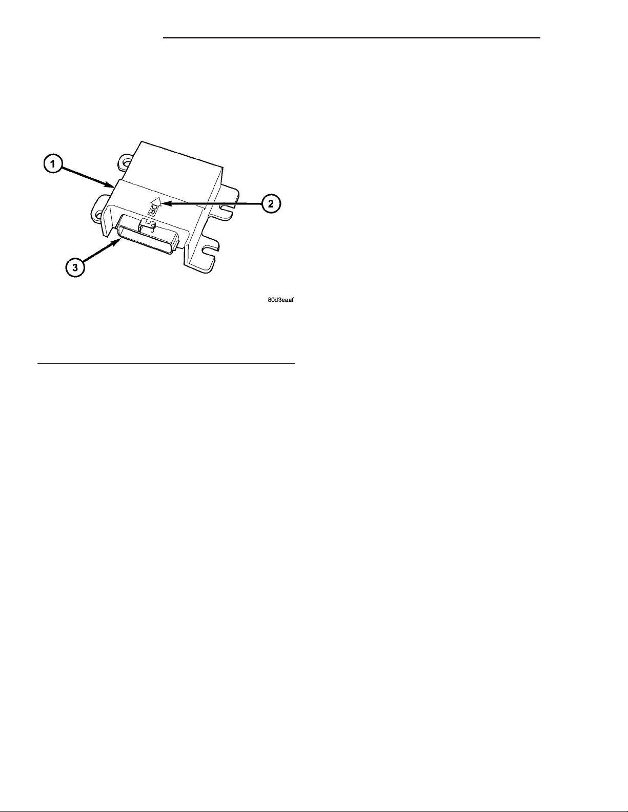
Fig. 7 Airbag Control Module
1 - AIRBAG CONTROL MODULE
2 - ORIENTATION ARROW
3 - CONNECTOR RECEPTACLE
The Airbag Control Module (ACM) is secured with
four screws to the top mounting surface of a stamped
steel bracket welded onto the top of the floor panel
transmission tunnel forward of the instrument panel
center support bracket and below the instrument
panel center stack in the passenger compartment of
the vehicle (Fig. 7). Concealed within a hollow in the
center of the die cast aluminum ACM housing is the
electronic circuitry of the ACM which includes a
microprocessor, an electronic impact sensor, an electromechanical safing sensor, and an energy storage
capacitor. A stamped metal cover plate is secured to
the bottom of the ACM housing with four screws to
enclose and protect the internal electronic circuitry
and components.
The ACM housing has integral mounting flanges
on each side. Two of the mounting flanges, one on
each side, have an integral locating pin on their
lower surface. The left flanges have round mounting
holes, while the flanges on the right side have slotted
mounting holes. An arrow cast into the top of the
ACM housing near the rear provides a visual verification of the proper orientation of the unit, and
should always be pointed toward the front of the
vehicle. A molded plastic electrical connector receptacle containing twenty-three terminal pins exits the
rearward facing side of the ACM housing. These terminal pins connect the ACM to the vehicle electrical
system through a dedicated take out and connector of
the instrument panel wire harness.
The impact sensor and safing sensor internal to
the ACM are calibrated for the specific vehicle, and
are only serviced as a unit with the ACM. The ACM
cannot be repaired or adjusted and, if damaged or
faulty, it must be replaced.
OPERATION
The microprocessor in the Airbag Control Module
(ACM) contains the front supplemental restraint system logic circuits and controls all of the front supplemental restraint system components. The ACM uses
On-Board Diagnostics (OBD) and can communicate
with other electronic modules in the vehicle as well
as with the DRBIIIt scan tool using the Programmable Communications Interface (PCI) data bus network. This method of communication is used for
control of the airbag indicator in the ElectroMechanical Instrument Cluster (EMIC) and for supplemental
restraint system diagnosis and testing through the
16-way data link connector located on the driver side
lower edge of the instrument panel. (Refer to 8 ELECTRICAL/INSTRUMENT CLUSTER/AIRBAG
INDICATOR - OPERATION).
The ACM microprocessor continuously monitors all
of the front supplemental restraint system electrical
circuits to determine the system readiness. If the
ACM detects a monitored system fault, it sets an
active and stored Diagnostic Trouble Code (DTC) and
sends electronic messages to the EMIC over the PCI
data bus to turn on the airbag indicator. An active
fault only remains for the duration of the fault, or in
some cases, the duration of the current ignition
switch cycle, while a stored fault causes a DTC to be
stored in memory by the ACM. For some DTCs, if a
fault does not recur for a number of ignition cycles,
the ACM will automatically erase the stored DTC.
For other internal faults, the stored DTC is latched
forever.
In standard cab models, the ACM also monitors a
resistor multiplexed input from the passenger airbag
on/off switch and provides a control output for the
Off indicator in the switch through a passenger airbag indicator driver circuit. If the passenger airbag
on/off switch is set to the Off position, the ACM turns
on the passenger airbag on/off switch Off indicator
and will internally disable the passenger airbag from
being deployed if an impact is detected that is sufficient for an airbag deployment. The ACM also turns
on the on/off switch Off indicator for about seven seconds each time the ignition switch is turned to the
On position as a bulb test. Following the bulb test,
the ACM controls the status of the Off indicator
based upon the resistance of the input from the on/off
switch. The ACM will also set and/or store a DTC for
faults it detects in the passenger airbag on/off switch
circuits, and will turn on the airbag indicator in the
EMIC if a fault has been detected.
Page 11

DR RESTRAINTS 8O - 11
AIRBAG CONTROL MODULE (Continued)
On models equipped with optional side curtain airbags, the ACM communicates with both the left and
right Side Impact Airbag Control Modules (SIACM)
over the PCI data bus. The SIACM notifies the ACM
when it has detected a monitored system fault and
stored a DTC in memory for its respective side curtain airbag system, and the ACM sets a DTC and
controls the airbag indicator operation accordingly.
The ACM receives battery current through two circuits; a fused ignition switch output (run) circuit
through a fuse in the Integrated Power Module
(IPM), and a fused ignition switch output (run-start)
circuit through a second fuse in the IPM. The ACM
receives ground through a ground circuit and take
out of the instrument panel wire harness. This take
out has a single eyelet terminal connector that is
secured by a ground screw to the instrument panel
support structure. These connections allow the ACM
to be operational whenever the ignition switch is in
the Start or On positions. The ACM also contains an
energy-storage capacitor. When the ignition switch is
in the Start or On positions, this capacitor is continually being charged with enough electrical energy to
deploy the front supplemental restraint components
for up to one second following a battery disconnect or
failure. The purpose of the capacitor is to provide
backup supplemental restraint system protection in
case there is a loss of battery current supply to the
ACM during an impact.
Two sensors are contained within the ACM; an
electronic impact sensor, and a safing sensor. The
electronic impact sensor is an accelerometer that
senses the rate of vehicle deceleration, which provides verification of the direction and severity of an
impact. The safing sensor is an electromechanical
sensor within the ACM that provides an additional
logic input to the ACM microprocessor. The safing
sensor is a normally open switch that is used to verify the need for a front supplemental restraint
deployment by detecting impact energy of a lesser
magnitude than that of the electronic impact sensor,
and must be closed in order for the front airbags or
seat belt tensioners to deploy. A pre-programmed
decision algorithm in the ACM microprocessor determines when the deceleration rate as signaled by the
impact sensor and the safing sensor indicate an
impact that is severe enough to require front supplemental restraint system protection and, based upon
the status of the passenger airbag on/off switch input
and the severity of the monitored impact, determines
what combination of seat belt tensioner and front airbag deployment is required for each front seating
position. When the programmed conditions are met,
the ACM sends the proper electrical signals to deploy
the seat belt tensioners and dual front airbags.
The hard wired inputs and outputs for the ACM
may be diagnosed and tested using conventional
diagnostic tools and procedures. However, conventional diagnostic methods will not prove conclusive in
the diagnosis of the ACM, the PCI data bus network,
or the electronic message inputs to and outputs from
the ACM. The most reliable, efficient, and accurate
means to diagnose the ACM, the PCI data bus network, and the electronic message inputs to and outputs from the ACM requires the use of a DRBIIIt
scan tool. Refer to the appropriate diagnostic information.
REMOVAL
WARNING: ON VEHICLES EQUIPPED WITH AIRBAGS, DISABLE THE SUPPLEMENTAL RESTRAINT
SYSTEM BEFORE ATTEMPTING ANY STEERING
WHEEL, STEERING COLUMN, DRIVER AIRBAG,
PASSENGER AIRBAG, SEAT BELT TENSIONER,
SIDE CURTAIN AIRBAG, OR INSTRUMENT PANEL
COMPONENT DIAGNOSIS OR SERVICE. DISCONNECT AND ISOLATE THE BATTERY NEGATIVE
(GROUND) CABLE, THEN WAIT TWO MINUTES FOR
THE SYSTEM CAPACITOR TO DISCHARGE BEFORE
PERFORMING FURTHER DIAGNOSIS OR SERVICE.
THIS IS THE ONLY SURE WAY TO DISABLE THE
SUPPLEMENTAL RESTRAINT SYSTEM. FAILURE TO
TAKE THE PROPER PRECAUTIONS COULD
RESULT IN ACCIDENTAL AIRBAG DEPLOYMENT
AND POSSIBLE PERSONAL INJURY.
WARNING: THE AIRBAG CONTROL MODULE CONTAINS THE IMPACT SENSOR, WHICH ENABLES
THE SYSTEM TO DEPLOY THE FRONT SUPPLEMENTAL RESTRAINTS. NEVER STRIKE OR DROP
THE AIRBAG CONTROL MODULE, AS IT CAN DAMAGE THE IMPACT SENSOR OR AFFECT ITS CALIBRATION. IF AN AIRBAG CONTROL MODULE IS
ACCIDENTALLY DROPPED DURING SERVICE, THE
MODULE MUST BE SCRAPPED AND REPLACED
WITH A NEW UNIT. FAILURE TO OBSERVE THIS
WARNING COULD RESULT IN ACCIDENTAL,
INCOMPLETE, OR IMPROPER FRONT SUPPLEMENTAL RESTRAINT DEPLOYMENT AND POSSIBLE
OCCUPANT INJURIES.
(1) Disconnect and isolate the battery negative
cable. Wait two minutes for the system capacitor to
discharge before further service.
(2) On models with a manual transmission,
remove the floor console from the top of the floor
panel transmission tunnel. (Refer to 23 - BODY/INTERIOR/FLOOR CONSOLE - REMOVAL).
(3) On models with an automatic transmission,
remove the ACM cover from the instrument panel.
Page 12
8O - 12 RESTRAINTS DR
AIRBAG CONTROL MODULE (Continued)
(Refer to 8 - ELECTRICAL/RESTRAINTS/ACM
COVER - REMOVAL).
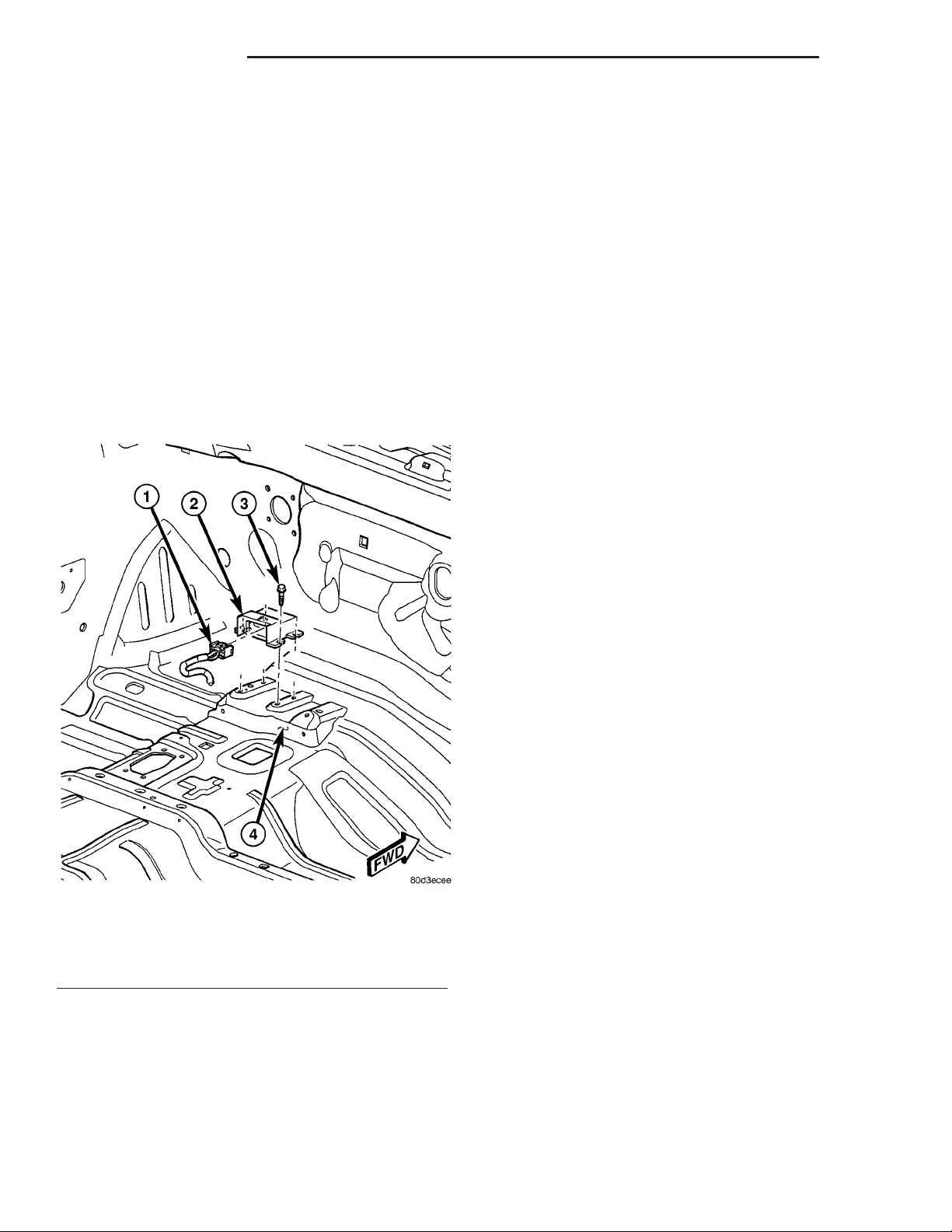
(4) Reach through the rearward facing opening
below the instrument panel center stack support
bracket on the top of the floor panel transmission
tunnel to access and disconnect the instrument panel
wire harness connector for the Airbag Control Module (ACM) from the ACM connector receptacle located
on the rearward facing side of the module (Fig. 8). To
disconnect the instrument panel wire harness connector from the ACM:
(a) Slide the red Connector Position Assurance
(CPA) lock on the top of the connector toward the
side of the connector.
(b) Depress the connector latch tab and pull the
connector straight away from the ACM connector
receptacle.
(7) Still working from the left side of the floor
panel transmission tunnel, lift the ACM upward far
enough to disengage the locating pins on the bottom
of the ACM mounting flanges from the locating holes
in the mounting bracket, then slide the ACM toward
the left far enough to disengage the slotted holes in
the right ACM mounting flanges from under the
heads of the two previously loosened right mounting
screws.
(8) Remove the ACM from the left side of the floor
panel transmission tunnel.
INSTALLATION
WARNING: ON VEHICLES EQUIPPED WITH AIRBAGS, DISABLE THE SUPPLEMENTAL RESTRAINT
SYSTEM BEFORE ATTEMPTING ANY STEERING
WHEEL, STEERING COLUMN, DRIVER AIRBAG,
PASSENGER AIRBAG, SEAT BELT TENSIONER,
SIDE CURTAIN AIRBAG, OR INSTRUMENT PANEL
COMPONENT DIAGNOSIS OR SERVICE. DISCONNECT AND ISOLATE THE BATTERY NEGATIVE
(GROUND) CABLE, THEN WAIT TWO MINUTES FOR
THE SYSTEM CAPACITOR TO DISCHARGE BEFORE
PERFORMING FURTHER DIAGNOSIS OR SERVICE.
THIS IS THE ONLY SURE WAY TO DISABLE THE
SUPPLEMENTAL RESTRAINT SYSTEM. FAILURE TO
TAKE THE PROPER PRECAUTIONS COULD
RESULT IN ACCIDENTAL AIRBAG DEPLOYMENT
AND POSSIBLE PERSONAL INJURY.
Fig. 8 Airbag Control Module Remove/Install
1 - WIRE HARNESS CONNECTOR
2 - AIRBAG CONTROL MODULE
3 - SCREW (4)
4 - FLOOR PANEL TRANSMISSION TUNNEL
(5) From the right side of the floor panel transmission tunnel, loosen each of the two screws that secure
the right side of the ACM to the bracket on the floor
panel transmission tunnel about 7 millimeters (0.25
inch).
(6) From the left side of the floor panel transmission tunnel, remove the two screws that secure the
left side of the ACM to the bracket on the floor panel
transmission tunnel.
WARNING: THE AIRBAG CONTROL MODULE CONTAINS THE IMPACT SENSOR, WHICH ENABLES
THE SYSTEM TO DEPLOY THE FRONT SUPPLEMENTAL RESTRAINTS. NEVER STRIKE OR DROP
THE AIRBAG CONTROL MODULE, AS IT CAN DAMAGE THE IMPACT SENSOR OR AFFECT ITS CALIBRATION. IF AN AIRBAG CONTROL MODULE IS
ACCIDENTALLY DROPPED DURING SERVICE, THE
MODULE MUST BE SCRAPPED AND REPLACED
WITH A NEW UNIT. FAILURE TO OBSERVE THIS
WARNING COULD RESULT IN ACCIDENTAL,
INCOMPLETE, OR IMPROPER FRONT SUPPLEMENTAL RESTRAINT DEPLOYMENT AND POSSIBLE
OCCUPANT INJURIES.
(1) Position the Airbag Control Module (ACM) to
the left side of the floor panel transmission tunnel
near the ACM bracket (Fig. 8). When the ACM is correctly positioned, the arrow on the ACM housing will
be pointed forward in the vehicle.
(2) From the left side of the floor panel transmission tunnel, slide the ACM toward the right far
enough to engage the slotted holes in the right ACM
mounting flanges under the heads of the two previously loosened right mounting screws, then engage
Page 13
DR RESTRAINTS 8O - 13
AIRBAG CONTROL MODULE (Continued)
the locating pins on the bottom of the ACM mounting
flanges into the locating holes in the bracket.
(3) Still working from the left side of the floor
panel transmission tunnel, install and tighten the
two screws that secure the left ACM mounting
flanges to the bracket that is welded onto the floor
panel transmission tunnel. Tighten the screws to 14
N·m (10 ft. lbs.).
(4) From the right side of the floor panel transmission tunnel, tighten each of the two screws that
secure the right side of the ACM to the bracket on
the floor panel transmission tunnel. Tighten the
screws to 14 N·m (10 ft. lbs.).
(5) Reach through the rearward facing opening
below the instrument panel center stack support
bracket on the top of the floor panel transmission
tunnel to access and reconnect the instrument panel
wire harness connector for the ACM to the ACM connector receptacle located on the rearward facing side
of the module. Be certain that the latch and the red
Connector Position Assurance (CPA) lock on the connector are each fully engaged.
(6) On models with an automatic transmission,
reinstall the ACM cover onto the instrument panel.
(Refer to 8 - ELECTRICAL/RESTRAINTS/ACM
COVER - INSTALLATION).
(7) On models with a manual transmission, reinstall the floor console onto the top of the floor panel
transmission tunnel. (Refer to 23 - BODY/INTERIOR/FLOOR CONSOLE - INSTALLATION).
(8) Do not reconnect the battery negative cable at
this time. The supplemental restraint system verification test procedure should be performed following
service of any supplemental restraint system component. (Refer to 8 - ELECTRICAL/RESTRAINTS STANDARD PROCEDURE - VERIFICATION TEST).
AUTOMATIC LOCKING
RETRACTOR
DESCRIPTION
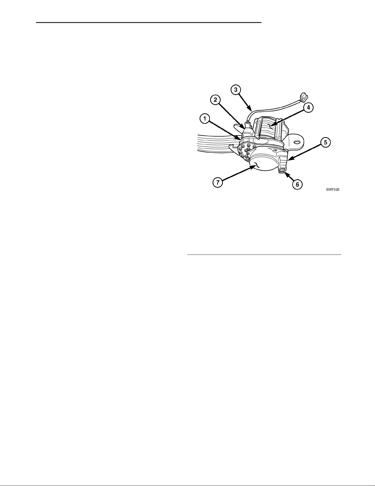
Fig. 9 Automatic Locking Retractor
1 - TENSIONER HOUSING OR CHAMBER
2 - GAS GENERATOR
3 - TENSIONER PIGTAIL WIRE
4 - SPOOL
5 - TENSION REDUCER (DRIVER SIDE ON STANDARD CAB
ONLY)
6 - REDUCER CONNECTOR RECEPTACLE
7 - RETRACTOR LOCKING MECHANISM COVER
The seat belt retractors used in all seating positions include an inertia-type, emergency locking
mechanism as standard equipment (Fig. 9). However,
the retractor locking mechanism for the passenger
side front seating position is mechanically switchable
from an emergency locking retractor to an automatic
locking retractor. The primary function of this feature is to securely accommodate a child seat in the
passenger side front seating position of the vehicle
without the need for a self-cinching seat belt tip half
latch plate unit or another supplemental device that
would be required to prevent the seat belt webbing
from unwinding freely from the retractor spool of an
inertia-type emergency locking retractor mechanism.
The automatic locking mechanism is integral to the
passenger side front seat belt and retractor unit and
is concealed beneath a molded plastic cover located
on the same side of the retractor spool as the seat
belt tensioner housing. The retractor is secured to
the inner B-pillar on the right side of the vehicle and
is concealed beneath the molded plastic inner B-pillar trim. The automatic locking mechanism cannot be
adjusted or repaired and, if faulty or damaged, the
entire passenger side front seat belt and retractor
unit must be replaced.
Page 14
8O - 14 RESTRAINTS DR
AUTOMATIC LOCKING RETRACTOR (Continued)
OPERATION
The automatic locking mode of the retractor is
engaged and the retractor is switched from operating
as a standard inertia-type emergency locking retractor by first buckling the combination lap and shoulder belt buckle. Then grasp the shoulder belt and
pull all of the webbing out of the retractor. Once all
of the belt webbing is extracted from the spool, the
retractor will automatically become engaged in the
pre-locked automatic locking mode and will make an
audible clicking or ratcheting sound as the shoulder
belt is allowed to retract to confirm that the automatic locking mode is now engaged. Once the automatic locking mode is engaged, the retractor will
remain locked and the belt will remain tight around
whatever it is restraining.
CHILD RESTRAINT ANCHOR
DESCRIPTION
The retractor is returned to standard emergency
locking mode by unbuckling the combination lap and
shoulder belt buckle and allowing the belt webbing to
be almost fully retracted onto the retractor spool. The
emergency locking mode is confirmed by the absence
of the audible clicking or ratcheting sound as the belt
webbing retracts. This mode will allow the belt to
unwind from and wind onto the retractor spool freely
unless and until a predetermined inertia load is
sensed, or until the retractor is again switched to the
automatic locking mode.
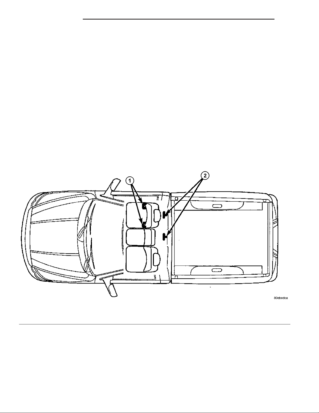
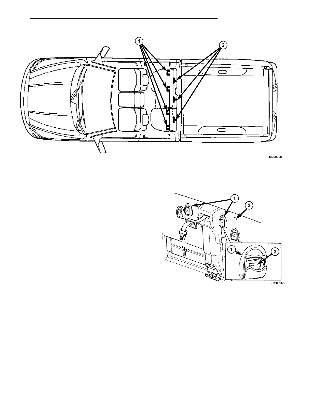
Fig. 10 Child Restraint Anchor Location - Standard Cab
1 - LOWERANCHOR (PROVIDED FOR OUTBOARD SEATING
POSITION ONLY)
2 - TETHER ANCHOR (PROVIDED FOR CENTER AND
OUTBOARD SEATING POSITIONS)
Page 15
DR RESTRAINTS 8O - 15
CHILD RESTRAINT ANCHOR (Continued)
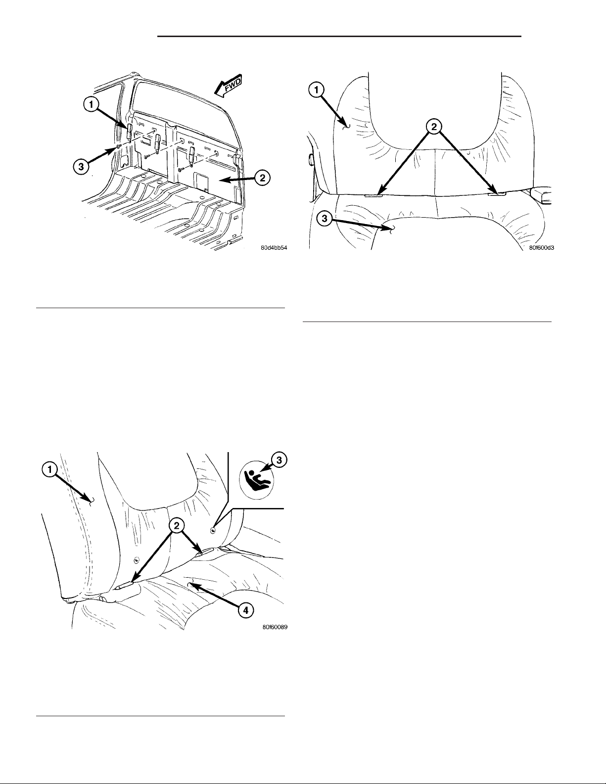
Fig. 11 Child Restraint Anchor Location - Quad Cab
1 - LOWERANCHOR (PROVIDED FOR REAR OUTBOARD
SEATING POSITIONS ONLY)
This model is equipped with a Lower Anchors and
Tether for CHildren, or LATCH child restraint
anchorage system (Fig. 10) or (Fig. 11). The LATCH
system provides for the installation of suitable child
restraints in certain seating positions without using
the standard equipment seat belt provided for that
seating position. Standard cab models are equipped
with a fixed-position child restraint upper tether
anchor for the front center and outboard seating positions, and child restraint lower anchors for the front
outboard seating position. Quad cab models are
equipped with a fixed-position child restraint upper
tether anchor strap for the rear center and both rear
outboard seating positions, and child restraint lower
anchors for both rear outboard seating positions. All
front seat child restraint anchors are deleted on quad
cab models.
The two upper tether anchors for standard cab
models are integral to the upper cab back panel reinforcement and are concealed behind individual trim
cover and bezel units that are integral to the cab
back trim panel (Fig. 12). These upper tether anchors
cannot be adjusted or repaired and, if faulty or damaged, they must be replaced as a unit with the upper
cab back panel reinforcement. The upper tether
anchor trim covers and bezels are serviced as a unit
with the cab back trim panel.
The three upper tether anchor straps for quad cab
models are secured to the upper cab back panel reinforcement with screws (Fig. 13). These anchor straps
are concealed behind the upright rear seat back. The
2 - TETHER ANCHOR (PROVIDED FOR REAR CENTER AND
OUTBOARD SEATING POSITIONS)
Fig. 12 Child Tether Anchor - Standard Cab
1 - COVER & BEZEL (2)
2 - CAB BACK TRIM PANEL
3 - ANCHOR (2)
upper tether anchor straps are available for individual service replacement.
The lower anchors for all models are integral to
their respective front or rear seat cushion frame (Fig.
14) or (Fig. 15). Round markers with an imprinted
child seat icon on the standard cab front seat back
trim cover helps identify the anchor locations for that
application because they may be otherwise difficult to
see with the seat back in the upright position. These
lower anchors are each constructed from round steel
Page 16
8O - 16 RESTRAINTS DR
CHILD RESTRAINT ANCHOR (Continued)
Fig. 13 Child Tether Strap - Quad Cab
1 - TETHER STRAP (3)
2 - CAB BACK PANEL
3 - SCREW (3)
bar stock that is formed into a U-shape, then
securely welded at each end to the seat cushion
frame. They are each accessed from the front of their
respective seats, at each side where the seat back
meets the seat cushion. These lower anchors cannot
be adjusted or repaired and, if faulty or damaged,
they must be replaced as a unit with the seat cushion frame. On quad cab models, if the lower anchors
have been bent or broken as a result of a vehicle collision, the latch for the affected rear seat cushion
frame unit must also be replaced.
Fig. 15 Child Restraint Lower Anchor - Quad Cab
Rear Seat
1 - REAR SEAT BACK
2 - LOWERANCHOR (2 PER OUTBOARD REAR SEATING
POSITION)
3 - REAR SEAT CUSHION
WARNING: DURING AND FOLLOWING ANY SEAT
BELT OR CHILD RESTRAINT ANCHOR SERVICE,
CAREFULLY INSPECT ALL SEAT BELTS, BUCKLES,
MOUNTING HARDWARE, RETRACTORS, TETHER
STRAPS, AND ANCHORS FOR PROPER INSTALLATION, OPERATION, OR DAMAGE. REPLACE ANY
BELT THAT IS CUT, FRAYED, OR TORN.
STRAIGHTEN ANY BELT THAT IS TWISTED.
TIGHTEN ANY LOOSE FASTENERS. REPLACE ANY
BELT THAT HAS A DAMAGED OR INOPERATIVE
BUCKLE OR RETRACTOR. REPLACE ANY BELT
THAT HAS A BENT OR DAMAGED LATCH PLATE
OR ANCHOR PLATE. REPLACE ANY CHILD
RESTRAINT ANCHOR OR THE UNIT TO WHICH THE
ANCHOR IS INTEGRAL THAT HAS BEEN BENT OR
DAMAGED. NEVER ATTEMPT TO REPAIR A SEAT
BELT OR CHILD RESTRAINT COMPONENT.
ALWAYS REPLACE DAMAGED OR FAULTY SEAT
BELT AND CHILD RESTRAINT COMPONENTS WITH
THE CORRECT, NEW AND UNUSED REPLACEMENT
PARTS LISTED IN THE DAIMLERCHRYSLER MOPAR
PARTS CATALOG.
Fig. 14 Child Restraint Lower Anchor - Standard
Cab Front Seat
1 - FRONT SEAT BACK
2 - LOWERANCHOR (2) - PASSENGER SIDE OUTBOARD
SEATING POSITION ONLY
3 - LOWERANCHOR MARKER (2)
4 - FRONT SEAT CUSHION
OPERATION
See the owner’s manual in the vehicle glove box for
more information on the proper use of all of the factory-installed child restraint anchors.
REMOVAL
The following procedure applies only to the rear
seat upper child tether straps used on quad cab models. The child restraint anchors used in other models
and locations are integral to other components and
cannot be serviced separately.
Page 17
DR RESTRAINTS 8O - 17
CHILD RESTRAINT ANCHOR (Continued)
WARNING: DURING AND FOLLOWING ANY SEAT
BELT OR CHILD RESTRAINT ANCHOR SERVICE,
CAREFULLY INSPECT ALL SEAT BELTS, BUCKLES,
MOUNTING HARDWARE, RETRACTORS, TETHER
STRAPS, AND ANCHORS FOR PROPER INSTALLATION, OPERATION, OR DAMAGE. REPLACE ANY
BELT THAT IS CUT, FRAYED, OR TORN.
STRAIGHTEN ANY BELT THAT IS TWISTED.
TIGHTEN ANY LOOSE FASTENERS. REPLACE ANY
BELT THAT HAS A DAMAGED OR INOPERATIVE
BUCKLE OR RETRACTOR. REPLACE ANY BELT
THAT HAS A BENT OR DAMAGED LATCH PLATE
OR ANCHOR PLATE. REPLACE ANY CHILD
RESTRAINT ANCHOR OR THE UNIT TO WHICH THE
ANCHOR IS INTEGRAL THAT HAS BEEN BENT OR
DAMAGED. NEVER ATTEMPT TO REPAIR A SEAT
BELT OR CHILD RESTRAINT COMPONENT.
ALWAYS REPLACE DAMAGED OR FAULTY SEAT
BELT AND CHILD RESTRAINT COMPONENTS WITH
THE CORRECT, NEW AND UNUSED REPLACEMENT
PARTS LISTED IN THE DAIMLERCHRYSLER MOPAR
PARTS CATALOG.
(1) Remove the rear seat from the vehicle. (Refer
to 23 - BODY/SEATS/SEAT - REAR - REMOVAL).
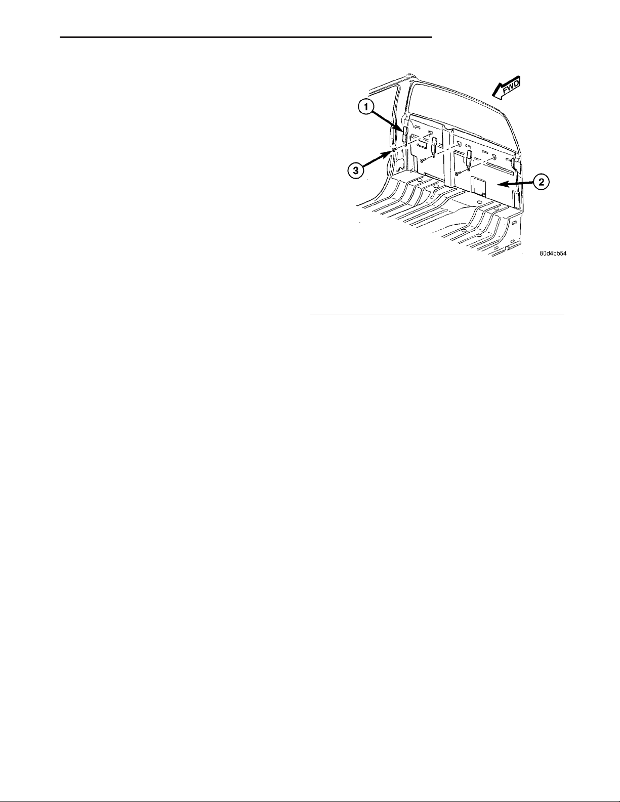
(2) Remove the screw that secures the child tether
strap to the upper cab back panel reinforcement (Fig.
16).
(3) Remove the child tether strap from the upper
cab back panel reinforcement.
INSTALLATION
The following procedure applies only to the rear
seat upper child tether straps used on quad cab models. The child restraint anchors used in other models
and locations are integral to other components and
cannot be serviced separately.
WARNING: DURING AND FOLLOWING ANY SEAT
BELT OR CHILD RESTRAINT ANCHOR SERVICE,
CAREFULLY INSPECT ALL SEAT BELTS, BUCKLES,
MOUNTING HARDWARE, RETRACTORS, TETHER
STRAPS, AND ANCHORS FOR PROPER INSTALLATION, OPERATION, OR DAMAGE. REPLACE ANY
BELT THAT IS CUT, FRAYED, OR TORN.
1 - TETHER STRAP (3)
2 - CAB BACK PANEL
3 - SCREW (3)
STRAIGHTEN ANY BELT THAT IS TWISTED.
TIGHTEN ANY LOOSE FASTENERS. REPLACE ANY
BELT THAT HAS A DAMAGED OR INOPERATIVE
BUCKLE OR RETRACTOR. REPLACE ANY BELT
THAT HAS A BENT OR DAMAGED LATCH PLATE
OR ANCHOR PLATE. REPLACE ANY CHILD
RESTRAINT ANCHOR OR THE UNIT TO WHICH THE
ANCHOR IS INTEGRAL THAT HAS BEEN BENT OR
DAMAGED. NEVER ATTEMPT TO REPAIR A SEAT
BELT OR CHILD RESTRAINT COMPONENT.
ALWAYS REPLACE DAMAGED OR FAULTY SEAT
BELT AND CHILD RESTRAINT COMPONENTS WITH
THE CORRECT, NEW AND UNUSED REPLACEMENT
PARTS LISTED IN THE DAIMLERCHRYSLER MOPAR
PARTS CATALOG.
cab back panel reinforcement (Fig. 16).
child tether strap to the upper cab back panel rein-
forcement. Tighten the screw to 14 N·m (10 ft. lbs.).
to 23 - BODY/SEATS/SEAT - REAR - INSTALLA-
TION).
Fig. 16 Child Tether Strap - Quad Cab
(1) Position the child tether strap onto the upper
(2) Install and tighten the screw that secures the
(3) Reinstall the rear seat into the vehicle. (Refer
Page 18
8O - 18 RESTRAINTS DR
CLOCKSPRING
DESCRIPTION
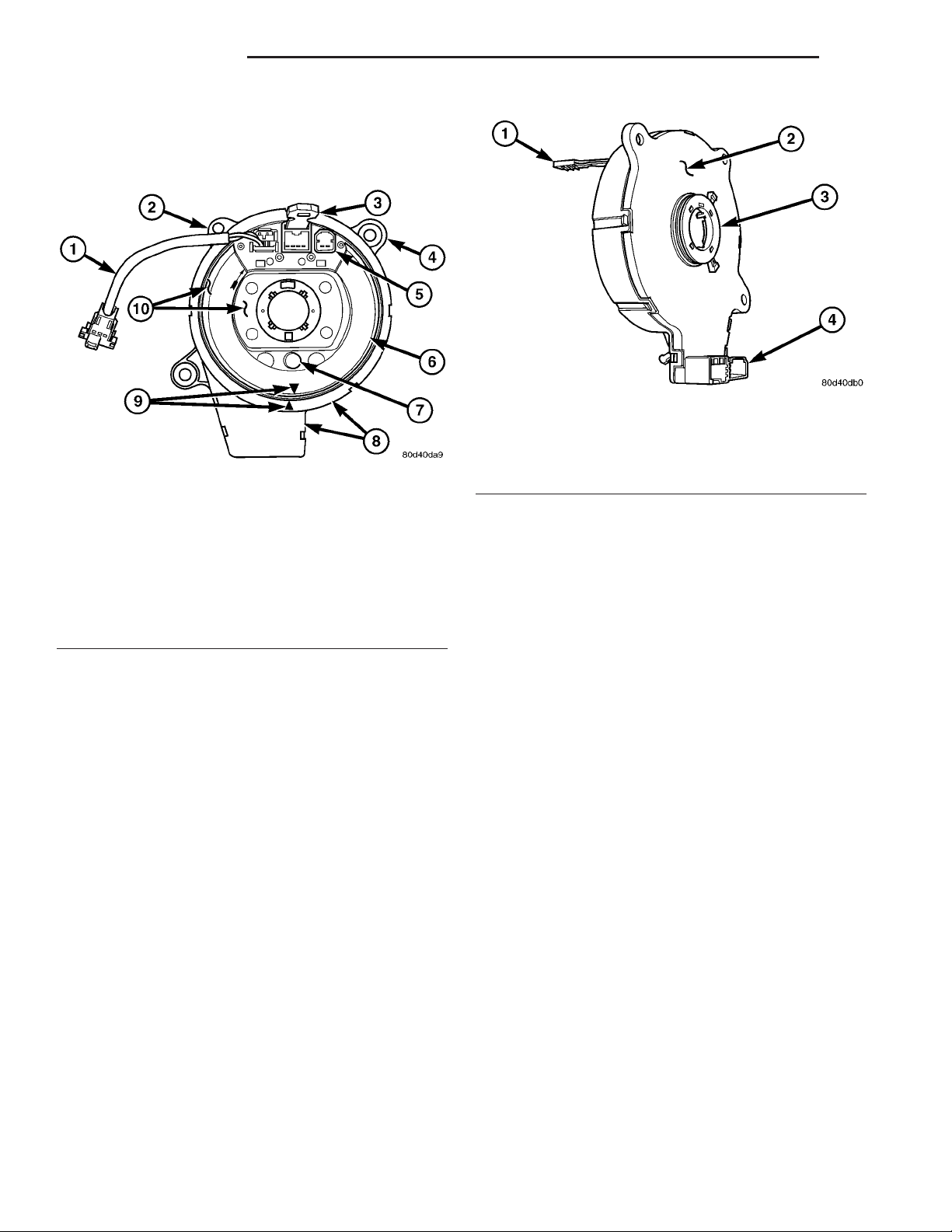
Fig. 18 Turn Signal Cancel Cam
1 - LOCKING PIN
2 - CLOCKSPRING CASE
3 - CANCEL CAM
Fig. 17 Clockspring
1 - PIGTAIL WIRE
2 - LOCATING TAB
3 - LOCKING PIN
4 - MOUNTING TAB (2)
5 - UPPER CONNECTOR RECEPTACLE (2)
6 - LABEL
7 - ENGAGEMENT DOWEL & BOOT
8 - CASE
9 - CENTERINGARROWS
10 - ROTOR
The clockspring assembly is secured with two
screws onto the multi-function switch mounting
housing near the top of the steering column behind
the steering wheel (Fig. 17). The clockspring consists
of a flat, round molded plastic case with a stubby tail
that hangs below the steering column (Fig. 18). The
tail contains two connector receptacles that face
toward the instrument panel. Within the plastic case
is a spool-like molded plastic rotor with a large
exposed hub. The upper surface of the rotor hub has
a large center hole, two large flats, an engagement
dowel with a yellow rubber boot, a short pigtail wire
with connector, and two connector receptacles that
face toward the steering wheel.
The lower surface of the rotor hub has a molded
plastic turn signal cancel cam with two lobes that is
keyed to the rotor and is secured there with four
integral snap features. Within the plastic case and
wound around the rotor spool is a long ribbon-like
tape that consists of several thin copper wire leads
sandwiched between two thin plastic membranes.
The outer end of the tape terminates at the connector
receptacles that face the instrument panel, while the
inner end of the tape terminates at the pigtail wire
and connector receptacles on the hub of the clockspring rotor that face the steering wheel.
4 - LOWER CONNECTOR RECEPTACLE (2)
Service replacement clocksprings are shipped precentered and with a molded plastic locking pin that
snaps into a receptacle on the rotor and is engaged
between two tabs on the upper surface of the rotor
case. The locking pin secures the centered clockspring rotor to the clockspring case during shipment,
but the locking pin must be removed from the clockspring after it is installed on the steering column.
(Refer to 8 - ELECTRICAL/RESTRAINTS/CLOCKSPRING - STANDARD PROCEDURE - CLOCKSPRING CENTERING).
The clockspring cannot be repaired. If the clockspring is faulty, damaged, or if the driver airbag has
been deployed, the clockspring must be replaced.
OPERATION
The clockspring is a mechanical electrical circuit
component that is used to provide continuous electrical continuity between the fixed instrument panel
wire harness and the electrical components mounted
on or in the rotating steering wheel. On this model
the rotating electrical components include the driver
airbag, the horn switch, the speed control switches,
and the remote radio switches, if the vehicle is so
equipped. The clockspring case is positioned and
secured to the multi-function switch mounting housing near the top of the steering column. The connector receptacles on the tail of the fixed clockspring
case connect the clockspring to the vehicle electrical
system through two take outs with connectors from
the instrument panel wire harness.
The clockspring rotor is movable and is keyed by
an engagement dowel that is molded onto the rotor
hub between two fins that are cast into the lower
surface of the steering wheel armature. A yellow rub-
Page 19

DR RESTRAINTS 8O - 19
CLOCKSPRING (Continued)
ber boot is installed over the engagement dowel to
eliminate contact noise between the dowel and the
steering wheel. The two lobes on the turn signal cancel cam on the lower surface of the clockspring rotor
hub contact a turn signal cancel actuator of the
multi-function switch to provide automatic turn signal cancellation. The yellow sleeved pigtail wires on
the upper surface of the clockspring rotor connect the
clockspring to the driver airbag, while a steering
wheel wire harness connects the two connector receptacles on the upper surface of the clockspring rotor to
the horn switch feed pigtail wire connector and, if
the vehicle is so equipped, to the optional speed control and remote radio switches on the steering wheel.
Like the clockspring in a timepiece, the clockspring
tape has travel limits and can be damaged by being
wound too tightly during full stop-to-stop steering
wheel rotation. To prevent this from occurring, the
clockspring is centered when it is installed on the
steering column. Centering the clockspring indexes
the clockspring tape to the movable steering components so that the tape can operate within its
designed travel limits. However, if the clockspring is
removed from the steering column or if the steering
shaft is disconnected from the steering gear, the
clockspring spool can change position relative to the
movable steering components. The clockspring must
be re-centered following completion of this service or
the tape may be damaged.
Service replacement clocksprings are shipped precentered and with a plastic locking pin installed.
This locking pin should not be disengaged until the
clockspring has been installed on the steering column. If the locking pin is removed or damaged before
the clockspring is installed on a steering column, the
clockspring centering procedure must be performed.
(Refer to 8 - ELECTRICAL/RESTRAINTS/CLOCKSPRING - STANDARD PROCEDURE - CLOCKSPRING CENTERING).
tion relative to the other steering components. The
clockspring must then be re-centered following completion of such service or the clockspring tape may be
damaged. Service replacement clocksprings are
shipped pre-centered, with a plastic locking pin
installed (Fig. 19). This locking pin should not be
removed until the clockspring has been installed on
the steering column. If the locking pin is removed
before the clockspring is installed on a steering column, the clockspring centering procedure must be
performed.
WARNING: ON VEHICLES EQUIPPED WITH AIRBAGS, DISABLE THE SUPPLEMENTAL RESTRAINT
SYSTEM BEFORE ATTEMPTING ANY STEERING
WHEEL, STEERING COLUMN, DRIVER AIRBAG,
PASSENGER AIRBAG, SEAT BELT TENSIONER,
SIDE CURTAIN AIRBAG, OR INSTRUMENT PANEL
COMPONENT DIAGNOSIS OR SERVICE. DISCONNECT AND ISOLATE THE BATTERY NEGATIVE
(GROUND) CABLE, THEN WAIT TWO MINUTES FOR
THE SYSTEM CAPACITOR TO DISCHARGE BEFORE
PERFORMING FURTHER DIAGNOSIS OR SERVICE.
THIS IS THE ONLY SURE WAY TO DISABLE THE
SUPPLEMENTAL RESTRAINT SYSTEM. FAILURE TO
TAKE THE PROPER PRECAUTIONS COULD
RESULT IN ACCIDENTAL AIRBAG DEPLOYMENT
AND POSSIBLE PERSONAL INJURY.
STANDARD PROCEDURE - CLOCKSPRING
CENTERING
The clockspring is designed to wind and unwind
when the steering wheel is rotated, but is only
designed to rotate the same number of turns (about
five complete rotations) as the steering wheel can be
turned from stop to stop. Centering the clockspring
indexes the clockspring tape to other steering components so that it can operate within its designed
travel limits. The rotor of a centered clockspring can
be rotated two and one-half turns in either direction
from the centered position, without damaging the
clockspring tape.
However, if the clockspring is removed for service
or if the steering column is disconnected from the
steering gear, the clockspring tape can change posi-
Fig. 19 Clockspring and Multi-Function Switch
1 - CLOCKSPRING
2 - LOCATING PIN
3 - SCREW (2)
4 - LOCKING PIN
5 - ENGAGEMENT DOWEL BOOT
Page 20

8O - 20 RESTRAINTS DR
CLOCKSPRING (Continued)
NOTE: Before starting this procedure, be certain to
turn the steering wheel until the front wheels are in
the straight-ahead position.
(1) Place the front wheels in the straight-ahead
position.
(2) Remove the clockspring from the steering column. (Refer to 8 - ELECTRICAL/RESTRAINTS/
CLOCKSPRING - REMOVAL).
(3) Rotate the clockspring rotor clockwise to the
end of its travel. Do not apply excessive torque.
(4) From the end of the clockwise travel, rotate the
rotor about two and one-half turns counterclockwise.
The engagement dowel and yellow rubber boot
should end up at the bottom, and the arrows on the
clockspring rotor and case should be in alignment.
The clockspring is now centered.
(5) The front wheels should still be in the straightahead position. Reinstall the clockspring onto the
steering column. (Refer to 8 - ELECTRICAL/RESTRAINTS/CLOCKSPRING - INSTALLATION).
REMOVAL
The clockspring cannot be repaired. It must be
replaced if faulty or damaged, or if the driver airbag
has been deployed.
WARNING: ON VEHICLES EQUIPPED WITH AIRBAGS, DISABLE THE SUPPLEMENTAL RESTRAINT
SYSTEM BEFORE ATTEMPTING ANY STEERING
WHEEL, STEERING COLUMN, DRIVER AIRBAG,
PASSENGER AIRBAG, SEAT BELT TENSIONER,
SIDE CURTAIN AIRBAG, OR INSTRUMENT PANEL
COMPONENT DIAGNOSIS OR SERVICE. DISCONNECT AND ISOLATE THE BATTERY NEGATIVE
(GROUND) CABLE, THEN WAIT TWO MINUTES FOR
THE SYSTEM CAPACITOR TO DISCHARGE BEFORE
PERFORMING FURTHER DIAGNOSIS OR SERVICE.
THIS IS THE ONLY SURE WAY TO DISABLE THE
SUPPLEMENTAL RESTRAINT SYSTEM. FAILURE TO
TAKE THE PROPER PRECAUTIONS COULD
RESULT IN ACCIDENTAL AIRBAG DEPLOYMENT
AND POSSIBLE PERSONAL INJURY.
NOTE: Before starting this procedure, be certain to
turn the steering wheel until the front wheels are in
the straight-ahead position.
(1) Place the front wheels in the straight ahead
position.
(2) Remove the driver airbag from the steering
wheel. (Refer to 8 - ELECTRICAL/RESTRAINTS/
DRIVER AIRBAG - REMOVAL).
(3) Disconnect the steering wheel wire harness
connectors from the upper clockspring connector
receptacles.
CAUTION: Be certain that the screws that secure
the steering wheel puller to the steering wheel are
fully engaged in the steering wheel armature without passing through the steering wheel and damaging the clockspring.
(4) Remove the steering wheel from the steering
column. (Refer to 19 - STEERING/COLUMN/STEERING WHEEL - REMOVAL).
(5) Remove the steering column opening cover
from the instrument panel. (Refer to 23 - BODY/INSTRUMENT PANEL/STEERING COLUMN OPENING COVER - REMOVAL).
(6) If the vehicle is so equipped, grasp the steering
column tilt knob firmly and pull it straight rearward
to remove it from the tilt adjuster mechanism lever
located on the left side of the column just below the
multi-function switch control stalk.
(7) From below the steering column, remove the
two outboard screws that secure the upper shroud to
the lower shroud.
(8) Using hand pressure, push gently inward on
both sides of the upper shroud near the parting line
between the upper and lower shrouds to release the
snap features that secure it to the lower shroud.
(9) Remove the upper shroud from the lower
shroud.
(10) From below the steering column, remove the
one center screw that secures the lower shroud to the
steering column lock housing.
(11) Remove the lower shroud from the steering
column.
(12) Disconnect the two instrument panel wire
harness connectors for the clockspring from the two
connector receptacles below the steering column on
the back of the clockspring housing.
(13) Remove the two screws that secure the clockspring to the multi-function switch mounting housing
(Fig. 20).
(14) Remove the clockspring from the multi-function switch mounting housing. The clockspring cannot be repaired. It must be replaced if faulty or
damaged, or if the driver airbag has been deployed.
(15) If the removed clockspring is to be reused, be
certain to secure the clockspring rotor to the clockspring case to maintain clockspring centering until it
is reinstalled on the steering column. If clockspring
centering is not maintained, the clockspring must be
centered again before it is reinstalled. (Refer to 8 ELECTRICAL/RESTRAINTS/CLOCKSPRING STANDARD PROCEDURE - CLOCKSPRING CENTERING).
Page 21

DR RESTRAINTS 8O - 21
CLOCKSPRING (Continued)
THIS IS THE ONLY SURE WAY TO DISABLE THE
SUPPLEMENTAL RESTRAINT SYSTEM. FAILURE TO
TAKE THE PROPER PRECAUTIONS COULD
RESULT IN ACCIDENTAL AIRBAG DEPLOYMENT
AND POSSIBLE PERSONAL INJURY.
NOTE: Before starting this procedure, be certain
that the front wheels are still in the straight-ahead
position.
(1) Carefully slide the centered clockspring down
over the steering column upper shaft until the hole
in the locating tab at the eleven o’clock position on
the clockspring case is engaged over the locating pin
on the multi-function switch mounting housing (Fig.
20).
(2) Install and tighten the two screws that secure
the clockspring to the multi-function switch mounting housing. Tighten the screws to 2 N·m (20 in.
lbs.).
(3) Reconnect the two instrument panel wire harness connectors for the clockspring to the two connec-
Fig. 20 Clockspring and Multi-Function Switch
1 - CLOCKSPRING
2 - LOCATING PIN
3 - SCREW (2)
4 - LOCKING PIN
5 - ENGAGEMENT DOWEL BOOT
INSTALLATION
The clockspring cannot be repaired. It must be
replaced if faulty or damaged, or if the driver airbag
has been deployed.
If the clockspring is not properly centered in relation to the steering wheel, steering shaft and steering gear, it may be damaged. (Refer to 8 ELECTRICAL/RESTRAINTS/CLOCKSPRING STANDARD PROCEDURE - CLOCKSPRING CENTERING). Service replacement clocksprings are
shipped pre-centered, with a plastic locking pin
installed. This locking pin should not be removed
until the clockspring has been installed on the steering column. If the locking pin is removed before the
clockspring is installed on a steering column, the
clockspring centering procedure must be performed.
WARNING: ON VEHICLES EQUIPPED WITH AIRBAGS, DISABLE THE SUPPLEMENTAL RESTRAINT
SYSTEM BEFORE ATTEMPTING ANY STEERING
WHEEL, STEERING COLUMN, DRIVER AIRBAG,
PASSENGER AIRBAG, SEAT BELT TENSIONER,
SIDE CURTAIN AIRBAG, OR INSTRUMENT PANEL
COMPONENT DIAGNOSIS OR SERVICE. DISCONNECT AND ISOLATE THE BATTERY NEGATIVE
(GROUND) CABLE, THEN WAIT TWO MINUTES FOR
THE SYSTEM CAPACITOR TO DISCHARGE BEFORE
PERFORMING FURTHER DIAGNOSIS OR SERVICE.
tor receptacles below the steering column on the back
of the clockspring housing.
(4) Position the lower shroud onto the steering col-
umn.
(5) From below the steering column, install and
tighten the one center screw that secures the lower
shroud to the steering column lock housing. Tighten
the screw to 2 N·m (20 in. lbs.).
(6) Position the upper shroud onto the steering column. If the vehicle is equipped with an automatic
transmission, be certain to engage the gearshift lever
gap hider into the openings in the right side of the
upper and lower shrouds.
(7) Align the snap features on the upper shroud
with the receptacles on the lower shroud and apply
hand pressure to snap them together.
(8) From below the steering column, install and
tighten the two screws that secure the upper shroud
to the lower shroud. Tighten the screws to 2 N·m (20
in. lbs.).
(9) If the vehicle is equipped with the optional tilt
steering column, align the steering column tilt knob
with the tilt adjuster mechanism lever located on the
left side of the column just below the multi-function
switch control stalk and, using hand pressure, push
the knob firmly onto the lever.
(10) Reinstall the steering column opening cover
onto the instrument panel. (Refer to 23 - BODY/INSTRUMENT PANEL/STEERING COLUMN OPENING COVER - INSTALLATION).
(11) If a new clockspring has been installed,
remove the locking pin that is securing the clockspring rotor to the clockspring case to maintain
clockspring centering.
Page 22

8O - 22 RESTRAINTS DR
CLOCKSPRING (Continued)
NOTE: When reinstalling the steering wheel, be certain to index the yellow rubber booted engagement
dowel on the upper surface of the clockspring rotor
between the two fins cast into the lower surface of
the steering wheel armature hub.
(12) Reinstall the steering wheel onto the steering
column. (Refer to 19 - STEERING/COLUMN/STEERING WHEEL - INSTALLATION).
(13) Reconnect the steering wheel wire harness
connectors to the upper clockspring connector receptacles. Be certain that the steering wheel wire harness is routed between the steering wheel back trim
cover and the steering wheel armature.
(14) Reinstall the driver airbag onto the steering
wheel. (Refer to 8 - ELECTRICAL/RESTRAINTS/
DRIVER AIRBAG - INSTALLATION).
DRIVER AIRBAG
DESCRIPTION
back of the trim cover. The stamped metal airbag
housing is secured by integral tabs that engage slotted locking blocks at the top and bottom of the trim
cover receptacle, an integral metal hook inserted
through a window in the vertical wall of the trim
cover receptacle at each side, and by three aluminum
blind rivets. This combination of fasteners locks the
trim cover securely in place on the airbag housing.
The resistive membrane-type horn switch is
secured with heat stakes to the inside surface of the
driver airbag trim cover, between the trim cover and
the folded airbag cushion. The horn switch ground
pigtail wire has an eyelet terminal connector that is
captured beneath a flanged nut on the upper right
inflator mounting stud on the back of the housing
(Fig. 22). The horn switch feed pigtail wire has a
black, molded plastic insulator that is secured by an
integral retainer in a locator hole near the upper left
corner of the airbag housing and is connected to the
vehicle electrical system through a dedicated take
out of the steering wheel wire harness. Both horn
switch wires are routed through integral routing
slots in the upper locking block of the trim cover
receptacle.
Fig. 21 Driver Airbag Trim Cover
1 - STEERING WHEEL
2 - TRIM COVER
The color-keyed, injection molded, thermoplastic
driver airbag protective trim cover is the most visible
part of the driver airbag (Fig. 21). The driver airbag
is located in the center of the steering wheel, where
it is secured with two screws to the armature of the
four-spoke steering wheel. All models have a Dodge
Ram logo embossed in the center of the trim cover.
Concealed beneath the driver airbag trim cover are
the horn switch, the folded airbag cushion, the airbag
cushion retainer, the airbag housing, the airbag inflator, and the retainers that secure the inflator to the
airbag housing.
The airbag cushion, housing, and inflator are
secured within an integral receptacle molded into the
Fig. 22 Driver Airbag Housing
1 - HOUSING
2 - HORN SWITCH FEED WIRE
3 - INFLATOR
4 - TRIM COVER RECEPTACLE
5 - HORN SWITCH GROUND WIRE
The airbag used in this model is a Next Generation-type that complies with revised federal airbag
standards to deploy with less force than those used
in some prior models. A 71.1 centimeter (28 inch)
diameter, radial deploying fabric cushion with internal tethers is used. The airbag inflator is a nonazide, pyrotechnic-type unit and is secured by four
flanged hex nuts to four studs on the airbag cushion
retainer ring to the back of the stamped metal airbag
housing. A connector receptacle on the driver airbag
Page 23

DR RESTRAINTS 8O - 23
DRIVER AIRBAG (Continued)
inflator connects the inflator initiator to the vehicle
electrical system through a yellow-jacketed, two-wire
pigtail harness of the clockspring.
The driver airbag cannot be repaired, and must be
replaced if deployed or in any way damaged.
OPERATION
The driver airbag is deployed by electrical signals
generated by the Airbag Control Module (ACM)
through the driver airbag squib circuit to the initiator in the airbag inflator. When the ACM sends the
proper electrical signal to the initiator the electrical
energy generates enough heat to initiate a small
pyrotechnic charge which, in turn ignites chemical
pellets within the inflator. Once ignited, these chemical pellets burn rapidly and produce a large quantity
of inert gas. The inflator is sealed to the back of the
airbag housing and a diffuser in the inflator directs
all of the inert gas into the airbag cushion, causing
the cushion to inflate. As the cushion inflates, the
driver airbag trim cover will split at predetermined
breakout lines, then fold back out of the way along
with the horn switch unit. Following an airbag
deployment, the airbag cushion quickly deflates by
venting the inert gas towards the instrument panel
through vent holes within the fabric used to construct the back (steering wheel side) panel of the airbag cushion.
Some of the chemicals used to create the inert gas
may be considered hazardous while in their solid
state before they are burned, but they are securely
sealed within the airbag inflator. Typically, all potentially hazardous chemicals are burned during an airbag deployment event. The inert gas that is produced
when the chemicals are burned is harmless. However, a small amount of residue from the burned
chemicals may cause some temporary discomfort if it
contacts the skin, eyes, or breathing passages. If skin
or eye irritation is noted, rinse the affected area with
plenty of cool, clean water. If breathing passages are
irritated, move to another area where there is plenty
of clean, fresh air to breath. If the irritation is not
alleviated by these actions, contact a physician.
REMOVAL
The following procedure is for replacement of a
faulty or damaged driver airbag. If the airbag is
faulty or damaged, but not deployed, review the recommended procedures for handling non-deployed
supplemental restraints. (Refer to 8 - ELECTRICAL/
RESTRAINTS - STANDARD PROCEDURE - HANDLING NON-DEPLOYED SUPPLEMENTAL
RESTRAINTS). If the driver airbag has been
deployed, review the recommended procedures for
service after a supplemental restraint deployment
before removing the airbag from the vehicle. (Refer to
8 - ELECTRICAL/RESTRAINTS - STANDARD PROCEDURE - SERVICE AFTER A SUPPLEMENTAL
RESTRAINT DEPLOYMENT).
WARNING: ON VEHICLES EQUIPPED WITH AIRBAGS, DISABLE THE SUPPLEMENTAL RESTRAINT
SYSTEM BEFORE ATTEMPTING ANY STEERING
WHEEL, STEERING COLUMN, DRIVER AIRBAG,
PASSENGER AIRBAG, SEAT BELT TENSIONER,
SIDE CURTAIN AIRBAG, OR INSTRUMENT PANEL
COMPONENT DIAGNOSIS OR SERVICE. DISCONNECT AND ISOLATE THE BATTERY NEGATIVE
(GROUND) CABLE, THEN WAIT TWO MINUTES FOR
THE SYSTEM CAPACITOR TO DISCHARGE BEFORE
PERFORMING FURTHER DIAGNOSIS OR SERVICE.
THIS IS THE ONLY SURE WAY TO DISABLE THE
SUPPLEMENTAL RESTRAINT SYSTEM. FAILURE TO
TAKE THE PROPER PRECAUTIONS COULD
RESULT IN ACCIDENTAL AIRBAG DEPLOYMENT
AND POSSIBLE PERSONAL INJURY.
WARNING: WHEN REMOVING A DEPLOYED AIRBAG, RUBBER GLOVES, EYE PROTECTION, AND A
LONG-SLEEVED SHIRT SHOULD BE WORN. THERE
MAY BE DEPOSITS ON THE AIRBAG CUSHION AND
OTHER INTERIOR SURFACES. IN LARGE DOSES,
THESE DEPOSITS MAY CAUSE IRRITATION TO THE
SKIN AND EYES.
(1) Disconnect and isolate the battery negative
cable. Wait two minutes for the system capacitor to
discharge before further service.
(2) From the underside of the steering wheel,
remove the two screws that secure the two trim covers or speed control switches to each side of the
driver airbag trim cover.
(3) From the top of the steering wheel, remove the
two trim covers or speed control switches from the
pockets on each side of the driver airbag trim cover
to access the driver airbag mounting screws.
(4) Remove the two screws that secure the driver
airbag to the steering wheel armature (Fig. 23).
(5) Pull the driver airbag away from the steering
wheel far enough to access the two electrical connections at the back of the airbag housing.
(6) Disconnect the steering wheel wire harness
horn switch feed take out connector from the horn
switch feed pigtail wire connector insulator located
on the back of the driver airbag housing.
Page 24

8O - 24 RESTRAINTS DR
DRIVER AIRBAG (Continued)
CEDURE - SERVICE AFTER A SUPPLEMENTAL
RESTRAINT DEPLOYMENT).
WARNING: ON VEHICLES EQUIPPED WITH AIRBAGS, DISABLE THE SUPPLEMENTAL RESTRAINT
SYSTEM BEFORE ATTEMPTING ANY STEERING
WHEEL, STEERING COLUMN, DRIVER AIRBAG,
PASSENGER AIRBAG, SEAT BELT TENSIONER,
SIDE CURTAIN AIRBAG, OR INSTRUMENT PANEL
COMPONENT DIAGNOSIS OR SERVICE. DISCONNECT AND ISOLATE THE BATTERY NEGATIVE
(GROUND) CABLE, THEN WAIT TWO MINUTES FOR
THE SYSTEM CAPACITOR TO DISCHARGE BEFORE
PERFORMING FURTHER DIAGNOSIS OR SERVICE.
THIS IS THE ONLY SURE WAY TO DISABLE THE
SUPPLEMENTAL RESTRAINT SYSTEM. FAILURE TO
Fig. 23 Driver Airbag Remove/Install
1 - CLOCKSPRING
2 - STEERING WHEEL
3 - HORN SWITCH FEED TAKE OUT
4 - DRIVERAIRBAG
5 - SCREW (2)
6 - CLOCKSPRING PIGTAIL WIRE
CAUTION: Do not pull on the clockspring pigtail
wires or pry on the connector insulator to disengage the connector from the driver airbag inflator
connector receptacle. Improper removal of these
pigtail wires and their connector insulators can
result in damage to the airbag circuits or connector
insulators.
(7) The clockspring driver airbag pigtail wire connector is secured by integral latches to the airbag
inflator connector receptacle, which is located on the
back of the driver airbag housing. Depress the
latches on each side of the connector insulator and
pull the insulator straight out from the airbag inflator to disconnect it from the connector receptacle.
(8) Remove the driver airbag from the steering
wheel.
(9) If the driver airbag has been deployed, the
clockspring must be replaced. (Refer to 8 - ELECTRICAL/RESTRAINTS/CLOCKSPRING - REMOVAL).
INSTALLATION
The following procedure is for replacement of a
faulty or damaged driver airbag. If the airbag is
faulty or damaged, but not deployed, review the recommended procedures for handling non-deployed
supplemental restraints. (Refer to 8 - ELECTRICAL/
RESTRAINTS - STANDARD PROCEDURE - HANDLING NON-DEPLOYED SUPPLEMENTAL
RESTRAINTS). If the driver airbag has been
deployed, review the recommended procedures for
service after a supplemental restraint deployment
before removing the airbag from the vehicle. (Refer to
8 - ELECTRICAL/RESTRAINTS - STANDARD PRO-
TAKE THE PROPER PRECAUTIONS COULD
RESULT IN ACCIDENTAL AIRBAG DEPLOYMENT
AND POSSIBLE PERSONAL INJURY.
WARNING: USE EXTREME CARE TO PREVENT ANY
FOREIGN MATERIAL FROM ENTERING THE DRIVER
AIRBAG, OR BECOMING ENTRAPPED BETWEEN
THE DRIVER AIRBAG CUSHION AND THE DRIVER
AIRBAG TRIM COVER. FAILURE TO OBSERVE THIS
WARNING COULD RESULT IN OCCUPANT INJURIES
UPON AIRBAG DEPLOYMENT.
WARNING: THE DRIVER AIRBAG TRIM COVER
MUST NEVER BE PAINTED. REPLACEMENT AIRBAGS ARE SERVICED WITH TRIM COVERS IN THE
ORIGINAL COLORS. PAINT MAY CHANGE THE WAY
IN WHICH THE MATERIAL OF THE TRIM COVER
RESPONDS TO AN AIRBAG DEPLOYMENT. FAILURE TO OBSERVE THIS WARNING COULD RESULT
IN OCCUPANT INJURIES UPON AIRBAG DEPLOYMENT.
(1) Position the driver airbag close enough to the
steering wheel to reconnect the two electrical connections at the back of the airbag housing.
(2) When installing the driver airbag, reconnect
the clockspring driver airbag pigtail wire connector
to the airbag inflator connector receptacle by pressing straight in on the connector (Fig. 23). You can be
certain that the connector is fully engaged in its
receptacle by listening carefully for a distinct, audible click as the connector latches snap into place.
(3) Reconnect the steering wheel wire harness
horn switch feed take out connector to the horn
switch feed pigtail wire connector insulator located
on the back of the driver airbag housing.
(4) Carefully position the driver airbag in the
steering wheel. Be certain that the clockspring pigtail wire and the steering wheel wire harness in the
Page 25

DR RESTRAINTS 8O - 25
DRIVER AIRBAG (Continued)
steering wheel hub area are not pinched between the
driver airbag and the steering wheel armature.
(5) Install and tighten the two screws that secure
the driver airbag to the steering wheel armature.
Tighten the screws to 14 N·m (120 in. lbs.).
(6) From the top of the steering wheel, position the
two trim covers or speed control switches into the
pockets on each side of the driver airbag trim cover.
(7) From the underside of the steering wheel,
install and tighten the two screws that secure the
two trim covers or speed control switches to each side
of the driver airbag trim cover. Tighten the screws to
2 N·m (15 in. lbs.).
(8) Do not reconnect the battery negative cable at
this time. The supplemental restraint system verification test procedure should be performed following
service of any supplemental restraint system component. (Refer to 8 - ELECTRICAL/RESTRAINTS STANDARD PROCEDURE - VERIFICATION TEST).
FRONT CENTER SEAT BELT &
RETRACTOR
the front center seat belt lower anchor latch plate
from the unique black, keyed lower anchor buckle.
Use an ignition key or a small screwdriver to depress
the small white release button on the anchor buckle.
(2) Move the front seat to its most forward position
for easiest access to the front center seat belt and
retractor unit.
(3) Using a trim stick or another suitable wide
flat-bladed tool, gently pry at each side of the front
center seat belt bezel on the cab back trim panel to
release the snap features that secure the bezel to the
panel (Fig. 24).
REMOVAL
A front center seat belt and retractor is used only
on standard cab models. Quad cab models have a lap
belt in the front center seating position. (Refer to 8 ELECTRICAL/RESTRAINTS/FRONT CENTER
SEAT BELT BUCKLE - REMOVAL).
WARNING: DURING AND FOLLOWING ANY SEAT
BELT OR CHILD RESTRAINT ANCHOR SERVICE,
CAREFULLY INSPECT ALL SEAT BELTS, BUCKLES,
MOUNTING HARDWARE, RETRACTORS, TETHER
STRAPS, AND ANCHORS FOR PROPER INSTALLATION, OPERATION, OR DAMAGE. REPLACE ANY
BELT THAT IS CUT, FRAYED, OR TORN.
STRAIGHTEN ANY BELT THAT IS TWISTED.
TIGHTEN ANY LOOSE FASTENERS. REPLACE ANY
BELT THAT HAS A DAMAGED OR INOPERATIVE
BUCKLE OR RETRACTOR. REPLACE ANY BELT
THAT HAS A BENT OR DAMAGED LATCH PLATE
OR ANCHOR PLATE. REPLACE ANY CHILD
RESTRAINT ANCHOR OR THE UNIT TO WHICH THE
ANCHOR IS INTEGRAL THAT HAS BEEN BENT OR
DAMAGED. NEVER ATTEMPT TO REPAIR A SEAT
BELT OR CHILD RESTRAINT COMPONENT.
ALWAYS REPLACE DAMAGED OR FAULTY SEAT
BELT AND CHILD RESTRAINT COMPONENTS WITH
THE CORRECT, NEW AND UNUSED REPLACEMENT
PARTS LISTED IN THE DAIMLERCHRYSLER MOPAR
PARTS CATALOG.
(1) Reach between the center of the front seat
cushion and front seat back to access and unbuckle
Fig. 24 Front Center Seat Belt Bezel
1 - TRIM PANEL
2 - BODY BRACKET
3 - SEAT BELT BRACKET
4 - SEAT BELT
5 - BEZEL
(4) Remove the bezel from the webbing of the front
center seat belt.
(5) Remove the trim from the cab back panel.
(Refer to 23 - BODY/INTERIOR/REAR CAB BACK
PANEL TRIM - REMOVAL).
(6) Remove the two screws that secure the belt
bracket of the front center seat belt to the body
bracket on the upper cab back panel reinforcement
(Fig. 25).
(7) Remove the belt bracket of the front center
seat belt from the body bracket on the upper cab
back panel reinforcement.
(8) Remove the two screws that secure the front
center seat belt retractor bracket to the floor panel
near the base of the cab back panel.
Page 26

8O - 26 RESTRAINTS DR
FRONT CENTER SEAT BELT & RETRACTOR (Continued)
DAMAGED. NEVER ATTEMPT TO REPAIR A SEAT
BELT OR CHILD RESTRAINT COMPONENT.
ALWAYS REPLACE DAMAGED OR FAULTY SEAT
BELT AND CHILD RESTRAINT COMPONENTS WITH
THE CORRECT, NEW AND UNUSED REPLACEMENT
PARTS LISTED IN THE DAIMLERCHRYSLER MOPAR
PARTS CATALOG.
(1) Position the front center seat belt and retractor
unit to the floor panel at the base of the cab back
panel to the right of center (Fig. 25).
(2) Install and tighten the two screws that secure
the front center seat belt retractor bracket to the
floor panel near the base of the cab back panel.
Tighten the screws to 40 N·m (29 ft. lbs.).
(3) Position the belt bracket of the front center
seat belt to the body bracket on the upper cab back
panel reinforcement.
(4) Install and tighten the two screws that secure
the belt bracket of the front center seat belt to the
body bracket on the upper cab back panel reinforcement. Tighten the screws to 20 N·m (15 ft. lbs.).
(5) Reinstall the trim onto the cab back panel.
Fig. 25 Front Center Seat Belt & Retractor Remove/
Install
1 - BODY BRACKET
2 - BELT BRACKET
3 - SCREW (2)
4 - SCREW (2)
5 - RETRACTOR
6 - FLOOR PANEL
7 - SEAT BELT
8 - CAB BACK PANEL
(9) Remove the front center seat belt and retractor
unit from the floor panel.
INSTALLATION
A front center seat belt and retractor is used only
on standard cab models. Quad cab models have a lap
belt in the front center seating position. (Refer to 8 ELECTRICAL/RESTRAINTS/FRONT CENTER
SEAT BELT BUCKLE - INSTALLATION).
(Refer to 23 - BODY/INTERIOR/REAR CAB BACK
PANEL TRIM - INSTALLATION).
(6) Route the webbing of the front center seat belt
through the bezel and position the bezel to the belt
opening near the top of the cab back trim panel (Fig.
24).
(7) Using hand pressure, press firmly and evenly
on each side of the front center seat belt bezel until it
snaps into place on the cab back trim panel.
(8) Move the front seat back to its rearward position.
(9) Reach between the center of the front seat
cushion and front seat back to access and buckle the
front center seat belt lower anchor latch plate to the
unique black, keyed lower anchor buckle.
FRONT CENTER SEAT BELT
WARNING: DURING AND FOLLOWING ANY SEAT
BELT OR CHILD RESTRAINT ANCHOR SERVICE,
CAREFULLY INSPECT ALL SEAT BELTS, BUCKLES,
MOUNTING HARDWARE, RETRACTORS, TETHER
STRAPS, AND ANCHORS FOR PROPER INSTALLATION, OPERATION, OR DAMAGE. REPLACE ANY
BELT THAT IS CUT, FRAYED, OR TORN.
STRAIGHTEN ANY BELT THAT IS TWISTED.
TIGHTEN ANY LOOSE FASTENERS. REPLACE ANY
BELT THAT HAS A DAMAGED OR INOPERATIVE
BUCKLE OR RETRACTOR. REPLACE ANY BELT
THAT HAS A BENT OR DAMAGED LATCH PLATE
OR ANCHOR PLATE. REPLACE ANY CHILD
RESTRAINT ANCHOR OR THE UNIT TO WHICH THE
ANCHOR IS INTEGRAL THAT HAS BEEN BENT OR
REMOVAL
A fixed position front center seat belt buckle is
located on the left side of the front center seat section (20 percent) used on all models. Standard cab
models also have a unique fixed position black, keyed
front center seat belt lower anchor buckle for the
three-point center seat belt lower anchor located on
the right side of the front center seat section. The following procedure also applies to the fixed position
front center seat lap belt located on the right side of
the front center seat section of all quad cab models.
The three-point front center seat belt and retractor
unit is only used on standard cab models. (Refer to 8
- ELECTRICAL/RESTRAINTS/FRONT CENTER
SEAT BELT & RETRACTOR - REMOVAL).
Page 27

DR RESTRAINTS 8O - 27
FRONT CENTER SEAT BELT (Continued)
WARNING: DURING AND FOLLOWING ANY SEAT
BELT OR CHILD RESTRAINT ANCHOR SERVICE,
CAREFULLY INSPECT ALL SEAT BELTS, BUCKLES,
MOUNTING HARDWARE, RETRACTORS, TETHER
STRAPS, AND ANCHORS FOR PROPER INSTALLATION, OPERATION, OR DAMAGE. REPLACE ANY
BELT THAT IS CUT, FRAYED, OR TORN.
STRAIGHTEN ANY BELT THAT IS TWISTED.
TIGHTEN ANY LOOSE FASTENERS. REPLACE ANY
BELT THAT HAS A DAMAGED OR INOPERATIVE
BUCKLE OR RETRACTOR. REPLACE ANY BELT
THAT HAS A BENT OR DAMAGED LATCH PLATE
OR ANCHOR PLATE. REPLACE ANY CHILD
RESTRAINT ANCHOR OR THE UNIT TO WHICH THE
ANCHOR IS INTEGRAL THAT HAS BEEN BENT OR
DAMAGED. NEVER ATTEMPT TO REPAIR A SEAT
BELT OR CHILD RESTRAINT COMPONENT.
ALWAYS REPLACE DAMAGED OR FAULTY SEAT
BELT AND CHILD RESTRAINT COMPONENTS WITH
THE CORRECT, NEW AND UNUSED REPLACEMENT
PARTS LISTED IN THE DAIMLERCHRYSLER MOPAR
PARTS CATALOG.
(1) Move the adjacent right or left front outboard
seat section (40 percent) to its most forward position
for easiest access to the front center seat belt buckle,
lap belt lower anchor, or unique black, keyed front
center seat belt lower anchor buckle (Fig. 26).
lower anchor, or unique black, keyed front center
seat belt lower anchor buckle to the center seat support bracket.
(3) From the front of the front seat, reach between
the center seat cushion and the adjacent right or left
front outboard seat cushion to access and remove the
front center seat belt buckle, lap belt unit, or unique
black, keyed front center seat belt lower anchor
buckle through the elastic strap on the side of the
center seat cushion.
(4) Remove the front center seat belt buckle, lap
belt unit, or unique black, keyed front center seat
belt lower anchor buckle from the front seat.
INSTALLATION
A fixed position front center seat belt buckle is
located on the left side of the front center seat section (20 percent) used on all models. Standard cab
models also have a unique fixed position black, keyed
front center seat belt lower anchor buckle for the
three-point center seat belt lower anchor located on
the right side of the front center seat section. The following procedure also applies to the fixed position
front center seat lap belt located on the right side of
the front center seat section of all quad cab models.
The three-point front center seat belt and retractor
unit is only used on standard cab models. (Refer to 8
- ELECTRICAL/RESTRAINTS/FRONT CENTER
SEAT BELT & RETRACTOR - INSTALLATION).
Fig. 26 Front Center Seat Belt Remove/Install
1 - FRONT CENTER SEAT BELT
2 - ELASTIC STRAP
3 - CENTER SEAT SUPPORT BRACKET
4 - INBOARD FRONT SEAT TRACK
5 - SCREW
6 - CENTER SEAT SECTION
(2) From behind the front seat, remove the screw
that secures the front center seat belt buckle, lap belt
WARNING: DURING AND FOLLOWING ANY SEAT
BELT OR CHILD RESTRAINT ANCHOR SERVICE,
CAREFULLY INSPECT ALL SEAT BELTS, BUCKLES,
MOUNTING HARDWARE, RETRACTORS, TETHER
STRAPS, AND ANCHORS FOR PROPER INSTALLATION, OPERATION, OR DAMAGE. REPLACE ANY
BELT THAT IS CUT, FRAYED, OR TORN.
STRAIGHTEN ANY BELT THAT IS TWISTED.
TIGHTEN ANY LOOSE FASTENERS. REPLACE ANY
BELT THAT HAS A DAMAGED OR INOPERATIVE
BUCKLE OR RETRACTOR. REPLACE ANY BELT
THAT HAS A BENT OR DAMAGED LATCH PLATE
OR ANCHOR PLATE. REPLACE ANY CHILD
RESTRAINT ANCHOR OR THE UNIT TO WHICH THE
ANCHOR IS INTEGRAL THAT HAS BEEN BENT OR
DAMAGED. NEVER ATTEMPT TO REPAIR A SEAT
BELT OR CHILD RESTRAINT COMPONENT.
ALWAYS REPLACE DAMAGED OR FAULTY SEAT
BELT AND CHILD RESTRAINT COMPONENTS WITH
THE CORRECT, NEW AND UNUSED REPLACEMENT
PARTS LISTED IN THE DAIMLERCHRYSLER MOPAR
PARTS CATALOG.
(1) From the front of the front seat, position the
front center seat belt buckle, lap belt unit, or unique
black, keyed front center seat belt lower anchor
Page 28

8O - 28 RESTRAINTS DR
FRONT CENTER SEAT BELT (Continued)
buckle between the center seat cushion and the adjacent right or left front outboard seat cushion.
(2) From the front of the front seat, reach between
the center seat cushion and the adjacent right or left
front outboard seat cushion to route the front center
seat belt buckle, lap belt unit lower anchor, or unique
black, keyed front center seat belt lower anchor
buckle through the elastic strap on the side of the
center seat cushion (Fig. 26).
(3) From behind the front seat, position the front
center seat belt buckle, lap belt lower anchor, or
unique black, keyed front center seat belt lower
anchor buckle to the center seat support bracket.
(4) Install and tighten the screw that secures the
front center seat belt buckle, lap belt lower anchor, or
unique black, keyed front center seat belt lower
anchor buckle to the center seat support bracket.
Tighten the screw to 40 N·m (29 ft. lbs.).
(5) Move the adjacent right or left front outboard
seat section (40 percent) back to its rearward position.
FRONT OUTBOARD SEAT
BELT & RETRACTOR
RESTRAINTS). If the seat belt tensioner has been
deployed, review the recommended procedures for
service after a supplemental restraint deployment
before removing the front outboard seat belt and
retractor from the vehicle. (Refer to 8 - ELECTRICAL/RESTRAINTS - STANDARD PROCEDURE SERVICE AFTER A SUPPLEMENTAL RESTRAINT
DEPLOYMENT).
WARNING: ON VEHICLES EQUIPPED WITH AIRBAGS, DISABLE THE SUPPLEMENTAL RESTRAINT
SYSTEM BEFORE ATTEMPTING ANY STEERING
WHEEL, STEERING COLUMN, DRIVER AIRBAG,
PASSENGER AIRBAG, SEAT BELT TENSIONER,
SIDE CURTAIN AIRBAG, OR INSTRUMENT PANEL
COMPONENT DIAGNOSIS OR SERVICE. DISCONNECT AND ISOLATE THE BATTERY NEGATIVE
(GROUND) CABLE, THEN WAIT TWO MINUTES FOR
THE SYSTEM CAPACITOR TO DISCHARGE BEFORE
PERFORMING FURTHER DIAGNOSIS OR SERVICE.
THIS IS THE ONLY SURE WAY TO DISABLE THE
SUPPLEMENTAL RESTRAINT SYSTEM. FAILURE TO
TAKE THE PROPER PRECAUTIONS COULD
RESULT IN ACCIDENTAL AIRBAG DEPLOYMENT
AND POSSIBLE PERSONAL INJURY.
REMOVAL
REMOVAL - STANDARD CAB
The following procedure is for replacement of a
faulty or damaged front outboard seat belt and
retractor unit, which includes a seat belt tensioner
for this model.(Refer to 8 - ELECTRICAL/RESTRAINTS/SEAT BELT TENSIONER - DESCRIPTION). The only component of this seat belt and
retractor unit that is available for individual service
replacement is the plastic web stop button that prevents the latch plate from falling to the floor while in
the stored position. Refer to the instructions supplied
with the service kit for the proper web stop button
replacement procedures.
The seat belt retractor on the driver’s side of standard cab models only also includes a tension reducer.
(Refer to 8 - ELECTRICAL/RESTRAINTS/TENSION
REDUCER - DESCRIPTION). The seat belt retractor
on the passenger’s side of all models includes a switchable automatic locking mechanism. (Refer to 8 ELECTRICAL/RESTRAINTS/AUTOMATIC LOCKING RETRACTOR - DESCRIPTION).
If the seat belt or retractor is faulty or damaged,
but the seat belt tensioner is not deployed, review
the recommended procedures for handling non-deployed supplemental restraints. (Refer to 8 - ELECTRICAL/RESTRAINTS - STANDARD PROCEDURE
- HANDLING NON-DEPLOYED SUPPLEMENTAL
WARNING: DURING AND FOLLOWING ANY SEAT
BELT OR CHILD RESTRAINT ANCHOR SERVICE,
CAREFULLY INSPECT ALL SEAT BELTS, BUCKLES,
MOUNTING HARDWARE, RETRACTORS, TETHER
STRAPS, AND ANCHORS FOR PROPER INSTALLATION, OPERATION, OR DAMAGE. REPLACE ANY
BELT THAT IS CUT, FRAYED, OR TORN.
STRAIGHTEN ANY BELT THAT IS TWISTED.
TIGHTEN ANY LOOSE FASTENERS. REPLACE ANY
BELT THAT HAS A DAMAGED OR INOPERATIVE
BUCKLE OR RETRACTOR. REPLACE ANY BELT
THAT HAS A BENT OR DAMAGED LATCH PLATE
OR ANCHOR PLATE. REPLACE ANY CHILD
RESTRAINT ANCHOR OR THE UNIT TO WHICH THE
ANCHOR IS INTEGRAL THAT HAS BEEN BENT OR
DAMAGED. NEVER ATTEMPT TO REPAIR A SEAT
BELT OR CHILD RESTRAINT COMPONENT.
ALWAYS REPLACE DAMAGED OR FAULTY SEAT
BELT AND CHILD RESTRAINT COMPONENTS WITH
THE CORRECT, NEW AND UNUSED REPLACEMENT
PARTS LISTED IN THE DAIMLERCHRYSLER MOPAR
PARTS CATALOG.
(1) Move the front seat to its most forward position
for easiest access to the lower seat belt anchor and
the B-pillar trim.
(2) Disconnect and isolate the battery negative
cable. Wait two minutes for the system capacitor to
discharge before further service.
Page 29

DR RESTRAINTS 8O - 29
FRONT OUTBOARD SEAT BELT & RETRACTOR (Continued)
(3) Remove the screw that secures the lower seat
belt anchor to the lower inner B-pillar (Fig. 27).
Fig. 27 Front Outboard Seat Belt & Retractor
Remove/Install - Standard Cab
1 - ADJUSTER
2 - UPPER TRIM PANEL
3 - TURNING LOOP
4 - SCREW
5 - TRIM COVER
6 - LOWER TRIM PANEL
7 - LOWERANCHOR
8 - SCREW
9 - SCREW
10 - RETRACTOR
11 - WIRE HARNESS CONNECTOR
12 - SCREW
13 - WEB GUIDE
14 - B-PILLAR
(4) Remove the lower seat belt anchor from the
lower inner B-pillar.
(5) Unsnap and remove the trim cover from the
front outboard seat belt turning loop to access the
screw that secures the turning loop to the height
adjuster on the upper inner B-pillar. Discard the
removed turning loop trim cover as it is not intended
for reuse.
(6) Remove the screw that secures the seat belt
turning loop to the height adjuster.
(7) Remove the seat belt turning loop from the
height adjuster.
(8) Remove the upper and lower trim from the
inner B-pillar. (Refer to 23 - BODY/INTERIOR/BPILLAR UPPER TRIM - REMOVAL) and (Refer to
23 - BODY/INTERIOR/B-PILLAR LOWER TRIM REMOVAL).
(9) Remove the screw that secures the seat belt
web guide to the inner B-pillar near the belt line.
(10) Remove the seat belt web guide from the
inner B-pillar.
(11) On the driver side only, disconnect the body
wire harness take out and white connector from the
connector receptacle for the seat belt tension reducer
located near the bottom of the retractor.
(12) Disengage the seat belt tensioner pigtail wire
retainer from the hole in the inner B-pillar sheet
metal.
(13) Disconnect the yellow seat belt tensioner pigtail wire connector from the body wire harness take
out and connector for the tensioner.
(14) Remove the screw that secures the lower
retractor bracket to the lower inner B-pillar below
the retractor mounting hole.
(15) Disengage the hooks on the upper retractor
bracket from the slots in the lower inner B-pillar
above the retractor mounting hole.
(16) Remove the front outboard seat belt and
retractor from the retractor mounting hole in the
lower inner B-pillar.
REMOVAL - QUAD CAB
The following procedure is for replacement of a
faulty or damaged front outboard seat belt and
retractor unit, which includes a seat belt tensioner
for this model. (Refer to 8 - ELECTRICAL/RESTRAINTS/SEAT BELT TENSIONER - DESCRIPTION). The only component of this seat belt and
retractor unit that is available for individual service
replacement is the plastic web stop button that prevents the latch plate from falling to the floor while in
the stored position. Refer to the instructions supplied
with the service kit for the proper web stop button
replacement procedures.
The seat belt retractor on the passenger’s side of
all models includes a switchable automatic locking
mechanism. (Refer to 8 - ELECTRICAL/RESTRAINTS/AUTOMATIC LOCKING RETRACTOR DESCRIPTION).
If the seat belt or retractor is faulty or damaged,
but the seat belt tensioner is not deployed, review
the recommended procedures for handling non-deployed supplemental restraints. (Refer to 8 - ELECTRICAL/RESTRAINTS - STANDARD PROCEDURE
- HANDLING NON-DEPLOYED SUPPLEMENTAL
RESTRAINTS). If the seat belt tensioner has been
deployed, review the recommended procedures for
service after a supplemental restraint deployment
before removing the front outboard seat belt and
retractor from the vehicle. (Refer to 8 - ELECTRICAL/RESTRAINTS - STANDARD PROCEDURE SERVICE AFTER A SUPPLEMENTAL RESTRAINT
DEPLOYMENT).
Page 30

8O - 30 RESTRAINTS DR
FRONT OUTBOARD SEAT BELT & RETRACTOR (Continued)
WARNING: ON VEHICLES EQUIPPED WITH AIRBAGS, DISABLE THE SUPPLEMENTAL RESTRAINT
SYSTEM BEFORE ATTEMPTING ANY STEERING
WHEEL, STEERING COLUMN, DRIVER AIRBAG,
PASSENGER AIRBAG, SEAT BELT TENSIONER,
SIDE CURTAIN AIRBAG, OR INSTRUMENT PANEL
COMPONENT DIAGNOSIS OR SERVICE. DISCONNECT AND ISOLATE THE BATTERY NEGATIVE
(GROUND) CABLE, THEN WAIT TWO MINUTES FOR
THE SYSTEM CAPACITOR TO DISCHARGE BEFORE
PERFORMING FURTHER DIAGNOSIS OR SERVICE.
THIS IS THE ONLY SURE WAY TO DISABLE THE
SUPPLEMENTAL RESTRAINT SYSTEM. FAILURE TO
TAKE THE PROPER PRECAUTIONS COULD
RESULT IN ACCIDENTAL AIRBAG DEPLOYMENT
AND POSSIBLE PERSONAL INJURY.
WARNING: DURING AND FOLLOWING ANY SEAT
BELT OR CHILD RESTRAINT ANCHOR SERVICE,
CAREFULLY INSPECT ALL SEAT BELTS, BUCKLES,
MOUNTING HARDWARE, RETRACTORS, TETHER
STRAPS, AND ANCHORS FOR PROPER INSTALLATION, OPERATION, OR DAMAGE. REPLACE ANY
BELT THAT IS CUT, FRAYED, OR TORN.
STRAIGHTEN ANY BELT THAT IS TWISTED.
TIGHTEN ANY LOOSE FASTENERS. REPLACE ANY
BELT THAT HAS A DAMAGED OR INOPERATIVE
BUCKLE OR RETRACTOR. REPLACE ANY BELT
THAT HAS A BENT OR DAMAGED LATCH PLATE
OR ANCHOR PLATE. REPLACE ANY CHILD
RESTRAINT ANCHOR OR THE UNIT TO WHICH THE
ANCHOR IS INTEGRAL THAT HAS BEEN BENT OR
DAMAGED. NEVER ATTEMPT TO REPAIR A SEAT
BELT OR CHILD RESTRAINT COMPONENT.
ALWAYS REPLACE DAMAGED OR FAULTY SEAT
BELT AND CHILD RESTRAINT COMPONENTS WITH
THE CORRECT, NEW AND UNUSED REPLACEMENT
PARTS LISTED IN THE DAIMLERCHRYSLER MOPAR
PARTS CATALOG.
(1) Move the front seat to its most forward position
for easiest access to the lower seat belt anchor and
the B-pillar trim.
(2) Disconnect and isolate the battery negative
cable. Wait two minutes for the system capacitor to
discharge before further service.
(3) Remove the screw that secures the lower seat
belt anchor to the floor panel near the base of the
inner B-pillar (Fig. 28).
(4) Remove the lower seat belt anchor from the
floor panel near the base of the inner B-pillar.
(5) Unsnap and remove the trim cover from the
front outboard seat belt turning loop to access the
screw that secures the turning loop to the height
adjuster on the upper inner B-pillar. Discard the
Fig. 28 Front Outboard Seat Belt & Retractor
Remove/Install - Quad Cab
1 - ADJUSTER
2 - UPPER TRIM PANEL
3 - B-PILLAR
4 - TURNING LOOP
5 - SCREW
6 - TRIM COVER
7 - SEAT BELT
8 - LOWER TRIM PANEL
9 - SCREW
10 - LOWERANCHOR
11 - SCREW
12 - RETRACTOR
13 - WIRE HARNESS CONNECTOR
14 - SCREW
15 - WEB GUIDE
removed turning loop trim cover as it is not intended
for reuse.
(6) Remove the screw that secures the seat belt
turning loop to the height adjuster.
(7) Remove the seat belt turning loop from the
height adjuster.
(8) Remove the upper and lower trim from the
inner B-pillar. (Refer to 23 - BODY/INTERIOR/BPILLAR UPPER TRIM - REMOVAL) and (Refer to
23 - BODY/INTERIOR/B-PILLAR LOWER TRIM REMOVAL).
(9) Remove the screw that secures the seat belt
web guide to the inner B-pillar near the belt line.
(10) Remove the seat belt web guide from the
inner B-pillar.
Page 31

DR RESTRAINTS 8O - 31
FRONT OUTBOARD SEAT BELT & RETRACTOR (Continued)
(11) Disengage the seat belt tensioner pigtail wire
retainer from the hole in the inner B-pillar sheet
metal.
(12) Disconnect the yellow seat belt tensioner pigtail wire connector from the body wire harness take
out and connector for the tensioner.
(13) Remove the screw that secures the lower
retractor bracket to the lower inner B-pillar below
the retractor mounting hole.
(14) Disengage the hooks on the upper retractor
bracket from the slots in the lower inner B-pillar
above the retractor mounting hole.
(15) Remove the front outboard seat belt and
retractor from the retractor mounting hole in the
lower inner B-pillar.
INSTALLATION
INSTALLATION - STANDARD CAB
The following procedure is for replacement of a
faulty or damaged front outboard seat belt and
retractor unit, which includes a seat belt tensioner
for this model. (Refer to 8 - ELECTRICAL/RESTRAINTS/SEAT BELT TENSIONER - DESCRIPTION). The only component of this seat belt and
retractor unit that is available for individual service
replacement is the plastic web stop button that prevents the latch plate from falling to the floor while in
the stored position. Refer to the instructions supplied
with the service kit for the proper web stop button
replacement procedures.
The seat belt retractor on the driver’s side of standard cab models only also includes a tension reducer.
(Refer to 8 - ELECTRICAL/RESTRAINTS/TENSION
REDUCER - DESCRIPTION). The seat belt retractor
on the passenger’s side of all models includes a switchable automatic locking mechanism. (Refer to 8 ELECTRICAL/RESTRAINTS/AUTOMATIC LOCKING RETRACTOR - DESCRIPTION).
If the seat belt or retractor is faulty or damaged,
but the seat belt tensioner is not deployed, review
the recommended procedures for handling non-deployed supplemental restraints. (Refer to 8 - ELECTRICAL/RESTRAINTS - STANDARD PROCEDURE
- HANDLING NON-DEPLOYED SUPPLEMENTAL
RESTRAINTS). If the seat belt tensioner has been
deployed, review the recommended procedures for
service after a supplemental restraint deployment
before removing the front outboard seat belt and
retractor from the vehicle. (Refer to 8 - ELECTRICAL/RESTRAINTS - STANDARD PROCEDURE SERVICE AFTER A SUPPLEMENTAL RESTRAINT
DEPLOYMENT).
WARNING: ON VEHICLES EQUIPPED WITH AIRBAGS, DISABLE THE SUPPLEMENTAL RESTRAINT
SYSTEM BEFORE ATTEMPTING ANY STEERING
WHEEL, STEERING COLUMN, DRIVER AIRBAG,
PASSENGER AIRBAG, SEAT BELT TENSIONER,
SIDE CURTAIN AIRBAG, OR INSTRUMENT PANEL
COMPONENT DIAGNOSIS OR SERVICE. DISCONNECT AND ISOLATE THE BATTERY NEGATIVE
(GROUND) CABLE, THEN WAIT TWO MINUTES FOR
THE SYSTEM CAPACITOR TO DISCHARGE BEFORE
PERFORMING FURTHER DIAGNOSIS OR SERVICE.
THIS IS THE ONLY SURE WAY TO DISABLE THE
SUPPLEMENTAL RESTRAINT SYSTEM. FAILURE TO
TAKE THE PROPER PRECAUTIONS COULD
RESULT IN ACCIDENTAL AIRBAG DEPLOYMENT
AND POSSIBLE PERSONAL INJURY.
WARNING: DURING AND FOLLOWING ANY SEAT
BELT OR CHILD RESTRAINT ANCHOR SERVICE,
CAREFULLY INSPECT ALL SEAT BELTS, BUCKLES,
MOUNTING HARDWARE, RETRACTORS, TETHER
STRAPS, AND ANCHORS FOR PROPER INSTALLATION, OPERATION, OR DAMAGE. REPLACE ANY
BELT THAT IS CUT, FRAYED, OR TORN.
STRAIGHTEN ANY BELT THAT IS TWISTED.
TIGHTEN ANY LOOSE FASTENERS. REPLACE ANY
BELT THAT HAS A DAMAGED OR INOPERATIVE
BUCKLE OR RETRACTOR. REPLACE ANY BELT
THAT HAS A BENT OR DAMAGED LATCH PLATE
OR ANCHOR PLATE. REPLACE ANY CHILD
RESTRAINT ANCHOR OR THE UNIT TO WHICH THE
ANCHOR IS INTEGRAL THAT HAS BEEN BENT OR
DAMAGED. NEVER ATTEMPT TO REPAIR A SEAT
BELT OR CHILD RESTRAINT COMPONENT.
ALWAYS REPLACE DAMAGED OR FAULTY SEAT
BELT AND CHILD RESTRAINT COMPONENTS WITH
THE CORRECT, NEW AND UNUSED REPLACEMENT
PARTS LISTED IN THE DAIMLERCHRYSLER MOPAR
PARTS CATALOG.
(1) Position the front outboard seat belt and
retractor to the retractor mounting hole in the lower
inner B-pillar (Fig. 27).
(2) Engage the hooks on the upper retractor
bracket into the slots in the lower inner B-pillar
above the retractor mounting hole.
(3) Install and tighten the screw that secures the
lower retractor bracket to the lower inner B-pillar
below the retractor mounting hole. Tighten the screw
to 40 N·m (29 ft. lbs.).
(4) Reconnect the yellow seat belt tensioner pigtail
wire connector to the body wire harness take out and
connector for the tensioner.
(5) Engage the seat belt tensioner pigtail wire
retainer into the hole in the inner B-pillar sheet
metal.
(6) On the driver side only, reconnect the body
wire harness take out and white connector to the
Page 32

8O - 32 RESTRAINTS DR
FRONT OUTBOARD SEAT BELT & RETRACTOR (Continued)
seat belt tension reducer connector receptacle near
the bottom of the retractor.
(7) Position the seat belt web guide to its mount-
ing location on the inner B-pillar near the belt line.
(8) Install and tighten the screw that secures the
seat belt web guide to the inner B-pillar. Tighten the
screw to 2 N·m (20 in. lbs.).
(9) Reinstall the upper and lower trim onto the
inner B-pillar. (Refer to 23 - BODY/INTERIOR/BPILLAR UPPER TRIM - INSTALLATION) and
(Refer to 23 - BODY/INTERIOR/B-PILLAR LOWER
TRIM - INSTALLATION).
(10) Position the seat belt turning loop onto the
height adjuster on the upper inner B-pillar.
(11) Install and tighten the screw that secures the
seat belt turning loop to the height adjuster. Tighten
the screw to 40 N·m (29 ft. lbs.).
(12) Engage the lower snap features of the new
trim cover over the front outboard seat belt turning
loop and, using hand pressure, press firmly and
evenly on the top of the trim cover until it snaps into
place.
(13) Position the lower seat belt anchor to the
lower inner B-pillar.
(14) Install and tighten the screw that secures the
lower seat belt anchor to the B-pillar. Tighten the
screw to 40 N·m (29 ft. lbs.).
(15) Do not reconnect the battery negative cable at
this time. The supplemental restraint system verification test procedure should be performed following
service of any supplemental restraint system component. (Refer to 8 - ELECTRICAL/RESTRAINTS STANDARD PROCEDURE - VERIFICATION TEST).
(16) Move the front seat back to its rearward position.
INSTALLATION - QUAD CAB
The following procedure is for replacement of a
faulty or damaged front outboard seat belt and
retractor unit, which includes a seat belt tensioner
for this model. (Refer to 8 - ELECTRICAL/RESTRAINTS/SEAT BELT TENSIONER - DESCRIPTION). The only component of this seat belt and
retractor unit that is available for individual service
replacement is the plastic web stop button that prevents the latch plate from falling to the floor while in
the stored position. Refer to the instructions supplied
with the service kit for the proper web stop button
replacement procedures.
The seat belt retractor on the passenger’s side of
all models includes a switchable automatic locking
mechanism. (Refer to 8 - ELECTRICAL/RESTRAINTS/AUTOMATIC LOCKING RETRACTOR DESCRIPTION).
If the seat belt or retractor is faulty or damaged,
but the seat belt tensioner is not deployed, review
the recommended procedures for handling non-deployed supplemental restraints. (Refer to 8 - ELECTRICAL/RESTRAINTS - STANDARD PROCEDURE
- HANDLING NON-DEPLOYED SUPPLEMENTAL
RESTRAINTS). If the seat belt tensioner has been
deployed, review the recommended procedures for
service after a supplemental restraint deployment
before removing the front outboard seat belt and
retractor from the vehicle. (Refer to 8 - ELECTRICAL/RESTRAINTS - STANDARD PROCEDURE SERVICE AFTER A SUPPLEMENTAL RESTRAINT
DEPLOYMENT).
WARNING: ON VEHICLES EQUIPPED WITH AIRBAGS, DISABLE THE SUPPLEMENTAL RESTRAINT
SYSTEM BEFORE ATTEMPTING ANY STEERING
WHEEL, STEERING COLUMN, DRIVER AIRBAG,
PASSENGER AIRBAG, SEAT BELT TENSIONER,
SIDE CURTAIN AIRBAG, OR INSTRUMENT PANEL
COMPONENT DIAGNOSIS OR SERVICE. DISCONNECT AND ISOLATE THE BATTERY NEGATIVE
(GROUND) CABLE, THEN WAIT TWO MINUTES FOR
THE SYSTEM CAPACITOR TO DISCHARGE BEFORE
PERFORMING FURTHER DIAGNOSIS OR SERVICE.
THIS IS THE ONLY SURE WAY TO DISABLE THE
SUPPLEMENTAL RESTRAINT SYSTEM. FAILURE TO
TAKE THE PROPER PRECAUTIONS COULD
RESULT IN ACCIDENTAL AIRBAG DEPLOYMENT
AND POSSIBLE PERSONAL INJURY.
WARNING: DURING AND FOLLOWING ANY SEAT
BELT OR CHILD RESTRAINT ANCHOR SERVICE,
CAREFULLY INSPECT ALL SEAT BELTS, BUCKLES,
MOUNTING HARDWARE, RETRACTORS, TETHER
STRAPS, AND ANCHORS FOR PROPER INSTALLATION, OPERATION, OR DAMAGE. REPLACE ANY
BELT THAT IS CUT, FRAYED, OR TORN.
STRAIGHTEN ANY BELT THAT IS TWISTED.
TIGHTEN ANY LOOSE FASTENERS. REPLACE ANY
BELT THAT HAS A DAMAGED OR INOPERATIVE
BUCKLE OR RETRACTOR. REPLACE ANY BELT
THAT HAS A BENT OR DAMAGED LATCH PLATE
OR ANCHOR PLATE. REPLACE ANY CHILD
RESTRAINT ANCHOR OR THE UNIT TO WHICH THE
ANCHOR IS INTEGRAL THAT HAS BEEN BENT OR
DAMAGED. NEVER ATTEMPT TO REPAIR A SEAT
BELT OR CHILD RESTRAINT COMPONENT.
ALWAYS REPLACE DAMAGED OR FAULTY SEAT
BELT AND CHILD RESTRAINT COMPONENTS WITH
THE CORRECT, NEW AND UNUSED REPLACEMENT
PARTS LISTED IN THE DAIMLERCHRYSLER MOPAR
PARTS CATALOG.
(1) Position the front outboard seat belt and
retractor to the retractor mounting hole in the lower
inner B-pillar (Fig. 28).
Page 33

DR RESTRAINTS 8O - 33
FRONT OUTBOARD SEAT BELT & RETRACTOR (Continued)
(2) Engage the hooks on the upper retractor
bracket into the slots in the lower inner B-pillar
above the retractor mounting hole.
(3) Install and tighten the screw that secures the
lower retractor bracket to the lower inner B-pillar
below the retractor mounting hole. Tighten the screw
to 40 N·m (29 ft. lbs.).
(4) Reconnect the yellow seat belt tensioner pigtail
wire connector to the body wire harness take out and
connector for the tensioner.
(5) Engage the seat belt tensioner pigtail wire
retainer into the hole in the inner B-pillar sheet
metal.
(6) Position the seat belt web guide to its mounting location on the inner B-pillar near the belt line.
(7) Install and tighten the screw that secures the
seat belt web guide to the inner B-pillar. Tighten the
screw to 2 N·m (20 in. lbs.).
(8) Reinstall the upper and lower trim onto the
inner B-pillar. (Refer to 23 - BODY/INTERIOR/BPILLAR UPPER TRIM - INSTALLATION) and
(Refer to 23 - BODY/INTERIOR/B-PILLAR LOWER
TRIM - INSTALLATION).
(9) Position the seat belt turning loop onto the
height adjuster on the upper inner B-pillar.
(10) Install and tighten the screw that secures the
seat belt turning loop to the height adjuster. Tighten
the screw to 40 N·m (29 ft. lbs.).
(11) Engage the lower snap features of the new
trim cover over the front outboard seat belt turning
loop and, using hand pressure, press firmly and
evenly on the top of the trim cover until it snaps into
place.
(12) Position the lower seat belt anchor to the floor
panel near the base of the inner B-pillar.
(13) Install and tighten the screw that secures the
lower seat belt anchor to the floor panel near the
base of the inner B-pillar. Tighten the screw to 40
N·m (29 ft. lbs.).
(14) Do not reconnect the battery negative cable at
this time. The supplemental restraint system verification test procedure should be performed following
service of any supplemental restraint system component. (Refer to 8 - ELECTRICAL/RESTRAINTS STANDARD PROCEDURE - VERIFICATION TEST).
(15) Move the front seat back to its rearward position.
FRONT OUTBOARD SEAT
BELT BUCKLE
REMOVAL
A traveling front outboard seat belt buckle is
located on the inboard side of each front outboard
seat section (40 percent) used on all models. The seat
belt buckle on the driver’s side front seat for all models also includes a seat belt switch. (Refer to 8 ELECTRICAL/RESTRAINTS/SEAT BELT SWITCH DESCRIPTION).
WARNING: DURING AND FOLLOWING ANY SEAT
BELT OR CHILD RESTRAINT ANCHOR SERVICE,
CAREFULLY INSPECT ALL SEAT BELTS, BUCKLES,
MOUNTING HARDWARE, RETRACTORS, TETHER
STRAPS, AND ANCHORS FOR PROPER INSTALLATION, OPERATION, OR DAMAGE. REPLACE ANY
BELT THAT IS CUT, FRAYED, OR TORN.
STRAIGHTEN ANY BELT THAT IS TWISTED.
TIGHTEN ANY LOOSE FASTENERS. REPLACE ANY
BELT THAT HAS A DAMAGED OR INOPERATIVE
BUCKLE OR RETRACTOR. REPLACE ANY BELT
THAT HAS A BENT OR DAMAGED LATCH PLATE
OR ANCHOR PLATE. REPLACE ANY CHILD
RESTRAINT ANCHOR OR THE UNIT TO WHICH THE
ANCHOR IS INTEGRAL THAT HAS BEEN BENT OR
DAMAGED. NEVER ATTEMPT TO REPAIR A SEAT
BELT OR CHILD RESTRAINT COMPONENT.
ALWAYS REPLACE DAMAGED OR FAULTY SEAT
BELT AND CHILD RESTRAINT COMPONENTS WITH
THE CORRECT, NEW AND UNUSED REPLACEMENT
PARTS LISTED IN THE DAIMLERCHRYSLER MOPAR
PARTS CATALOG.
(1) Move the right or left front outboard seat section (40 percent) to its most rearward position and
tilt the seat back forward for easiest access to the
front outboard seat belt buckle lower anchor.
(2) For easiest access to the front outboard seat
belt buckle lower anchor on standard cab models,
also move the outboard seat section (40 percent)
opposite the side from which the buckle is to be
removed to its most forward position and tilt the seat
back forward.
(3) On standard cab models only, remove the stowage tray from the rear floor panel behind the seat.
(Refer to 23 - BODY/INTERIOR/REAR FLOOR
STOWAGE TRAY - REMOVAL).
(4) From behind the front seat on the driver side
only, disconnect the seat belt switch pigtail wire connector from the seat wire harness take out and connector for the switch located below the inboard edge
of the driver side inboard seat track just forward of
the buckle lower anchor (Fig. 29).
(5) From behind the front seat, remove the screw
that secures the front outboard seat belt buckle lower
anchor to the bracket on the inboard seat track.
(6) From the front of the front seat, reach between
the center seat cushion and the adjacent right or left
front outboard seat cushion to access and remove the
front outboard seat belt buckle from the seat.
Page 34

8O - 34 RESTRAINTS DR
FRONT OUTBOARD SEAT BELT BUCKLE (Continued)
PARTS LISTED IN THE DAIMLERCHRYSLER MOPAR
PARTS CATALOG.
(1) From the front of the front seat, reach between
the center seat cushion and the adjacent right or left
front outboard seat cushion to position the front outboard seat belt buckle to the seat (Fig. 29).
(2) From behind the front seat, install and tighten
the screw that secures the front outboard seat belt
buckle lower anchor to the bracket on the inboard
seat track. Tighten the screw to 25 N·m (18 ft. lbs.).
(3) From behind the front seat on the driver side
only, reconnect the seat belt switch pigtail wire connector to the seat wire harness take out and connector for the switch located below the inboard edge of
the driver side inboard seat track just forward of the
buckle lower anchor.
(4) On standard cab models only, reinstall the
stowage tray onto the rear floor panel behind the
seat. (Refer to 23 - BODY/INTERIOR/REAR FLOOR
Fig. 29 Front Outboard Seat Belt Buckle Remove/
Install
1 - DRIVER SIDE FRONT OUTBOARD SEAT BELT BUCKLE
2 - SEAT CUSHION
3 - PIGTAIL WIRE
4 - INBOARD SEAT TRACK
5 - SCREW
STOWAGE TRAY - INSTALLATION).
(5) On standard cab models, move the outboard
seat section (40 percent) opposite the side from which
the buckle was replaced to its most rearward position
and tilt the seat back to its upright position.
INSTALLATION
A traveling front outboard seat belt buckle is
located on the inboard side of each front outboard
seat section (40 percent) used on all models. The seat
belt buckle on the driver’s side front seat for all models also includes a seat belt switch. (Refer to 8 ELECTRICAL/RESTRAINTS/SEAT BELT SWITCH DESCRIPTION).
WARNING: DURING AND FOLLOWING ANY SEAT
BELT OR CHILD RESTRAINT ANCHOR SERVICE,
CAREFULLY INSPECT ALL SEAT BELTS, BUCKLES,
MOUNTING HARDWARE, RETRACTORS, TETHER
STRAPS, AND ANCHORS FOR PROPER INSTALLATION, OPERATION, OR DAMAGE. REPLACE ANY
BELT THAT IS CUT, FRAYED, OR TORN.
STRAIGHTEN ANY BELT THAT IS TWISTED.
TIGHTEN ANY LOOSE FASTENERS. REPLACE ANY
BELT THAT HAS A DAMAGED OR INOPERATIVE
BUCKLE OR RETRACTOR. REPLACE ANY BELT
THAT HAS A BENT OR DAMAGED LATCH PLATE
OR ANCHOR PLATE. REPLACE ANY CHILD
RESTRAINT ANCHOR OR THE UNIT TO WHICH THE
ANCHOR IS INTEGRAL THAT HAS BEEN BENT OR
DAMAGED. NEVER ATTEMPT TO REPAIR A SEAT
BELT OR CHILD RESTRAINT COMPONENT.
ALWAYS REPLACE DAMAGED OR FAULTY SEAT
BELT AND CHILD RESTRAINT COMPONENTS WITH
THE CORRECT, NEW AND UNUSED REPLACEMENT
PASSENGER AIRBAG
DESCRIPTION
Fig. 30 Passenger Airbag Door
1 - PASSENGER AIRBAG DOOR
2 - PANEL OUTLET (2)
3 - GLOVE BOX DOOR
The rearward facing surface of the injection
molded, thermoplastic passenger airbag door is the
most visible part of the passenger airbag (Fig. 30).
The passenger airbag door is located above the glove
box opening on the instrument panel in front of the
front seat passenger seating position. The upper and
outboard edges of the airbag door are secured with
Page 35

DR RESTRAINTS 8O - 35
PASSENGER AIRBAG (Continued)
seven integral snap features to the instrument panel
base trim, while two screws secure the integral
inboard mounting flange to the base trim, and four
screws secure the lower mounting flange to the upper
glove box opening reinforcement integral to the
instrument panel structural support. The passenger
airbag door includes two air conditioning panel outlets and their housings. Each of the panel outlet
housings feature four snap features that secure them
to the back of the airbag door and two mounting tabs
that are also secured with one screw each to the
upper glove box opening reinforcement.
Located behind the passenger airbag door within
the instrument panel is the passenger airbag unit
(Fig. 31). The passenger airbag housing fits into a
molded receptacle on the back of the airbag door,
where six stamped hook formations on the upper and
lower edges of the airbag housing are engaged in six
small window openings on the upper and lower
flanges of the receptacle to secure the airbag door to
the airbag housing. The inboard airbag door fasteners and mounting flange are concealed beneath the
instrument panel center bezel, while the lower fasteners and mounting flange are concealed beneath
the instrument panel lower surround. The passenger
airbag unit is secured by four screws through four
brackets (two front and two rear) that are integral to
the base of the airbag housing to the instrument
panel structural support.
those used in some prior models. The passenger airbag unit consists of a stamped and welded metal
housing, the airbag cushion, the airbag inflator, and
a stamped metal airbag and inflator retainer plate
that is secured to the airbag housing with six studs
and nuts. The airbag housing contains the airbag
inflator and the folded airbag cushion. An approximately 80 centimeter (31.5 inch) wide by 90 centimeter (35.5 inch) high rectangular fabric cushion is
used. The airbag inflator is a non-azide, pyrotechnictype unit that is secured to and sealed within the airbag housing. The inflator initiator is connected to the
vehicle electrical system through a dedicated take
out and connector of the instrument panel wire harness.
The passenger airbag includes the airbag door and
the two panel outlet housings. This unit cannot be
repaired, and must be replaced if deployed, faulty, or
in any way damaged.
OPERATION
The passenger airbag is deployed by an electrical
signal generated by the Airbag Control Module
(ACM) through the passenger airbag squib circuits to
the initiator in the airbag inflator. The hybrid-type
inflator assembly includes a small canister of highly
compressed inert gas. When the ACM sends the
proper electrical signal to the airbag inflator, the initiator converts the electrical energy into chemical
energy. This chemical energy produces the pressure
necessary to rupture a burst disk in the inert gas
canister.
The inflator is sealed to the airbag cushion so that
all of the released inert gas is directed into the airbag cushion, causing the cushion to inflate. As the
cushion inflates, the passenger airbag door will split
at predetermined tear seam lines concealed on the
inside surface of the door, then the door will pivot up
over the top of the instrument panel and out of the
way. Following a passenger airbag deployment, the
airbag cushion quickly deflates by venting the inert
gas through vent holes within the fabric used to construct the back (instrument panel side) of the airbag
cushion.
Fig. 31 Passenger Airbag Unit
1 - DOOR
2 - PANEL OUTLET HOUSING (2)
3 - SNAP FEATURE (7)
4 - REAR BRACKET (2)
5 - PIGTAIL WIRE CONNECTOR
6 - INFLATOR
7 - FRONT BRACKET (2)
8 - HOUSING
The passenger airbag unit used in this model is a
Next Generation-type that complies with revised federal airbag standards to deploy with less force than
REMOVAL
The following procedure is for replacement of a
faulty or damaged passenger airbag. If the airbag is
faulty or damaged, but not deployed, review the recommended procedures for handling non-deployed
supplemental restraints. (Refer to 8 - ELECTRICAL/
RESTRAINTS - STANDARD PROCEDURE - HANDLING NON-DEPLOYED SUPPLEMENTAL
RESTRAINTS). If the passenger airbag has been
deployed, review the recommended procedures for
service after a supplemental restraint deployment
Page 36

8O - 36 RESTRAINTS DR
PASSENGER AIRBAG (Continued)
before removing the airbag from the vehicle. (Refer to
8 - ELECTRICAL/RESTRAINTS - STANDARD PROCEDURE - SERVICE AFTER A SUPPLEMENTAL
RESTRAINT DEPLOYMENT).
WARNING: ON VEHICLES EQUIPPED WITH AIRBAGS, DISABLE THE SUPPLEMENTAL RESTRAINT
SYSTEM BEFORE ATTEMPTING ANY STEERING
WHEEL, STEERING COLUMN, DRIVER AIRBAG,
PASSENGER AIRBAG, SEAT BELT TENSIONER,
SIDE CURTAIN AIRBAG, OR INSTRUMENT PANEL
COMPONENT DIAGNOSIS OR SERVICE. DISCONNECT AND ISOLATE THE BATTERY NEGATIVE
(GROUND) CABLE, THEN WAIT TWO MINUTES FOR
THE SYSTEM CAPACITOR TO DISCHARGE BEFORE
PERFORMING FURTHER DIAGNOSIS OR SERVICE.
THIS IS THE ONLY SURE WAY TO DISABLE THE
SUPPLEMENTAL RESTRAINT SYSTEM. FAILURE TO
TAKE THE PROPER PRECAUTIONS COULD
RESULT IN ACCIDENTAL AIRBAG DEPLOYMENT
AND POSSIBLE PERSONAL INJURY.
WARNING: WHEN REMOVING A DEPLOYED AIRBAG, RUBBER GLOVES, EYE PROTECTION, AND A
LONG-SLEEVED SHIRT SHOULD BE WORN. THERE
MAY BE DEPOSITS ON THE AIRBAG UNIT AND
OTHER INTERIOR SURFACES. IN LARGE DOSES,
THESE DEPOSITS MAY CAUSE IRRITATION TO THE
SKIN AND EYES.
(1) Disconnect and isolate the battery negative
cable. Wait two minutes for the system capacitor to
discharge before further service.
(2) Remove the lower surround from the instrument panel. (Refer to 23 - BODY/INSTRUMENT
PANEL/LOWER SURROUND - REMOVAL).
(3) Remove the two screws that secure the mounting tabs of the two panel outlet housings to the
upper glove box opening reinforcement (Fig. 32).
(4) Remove the six screws that secure the inboard
and lower flanges of the passenger airbag door to the
instrument panel.
(5) Reach through and above the glove box opening
to access and remove the two screws that secure the
passenger airbag rear brackets to the upper glove
box opening reinforcement (Fig. 33).
Fig. 33 Passenger Airbag Remove/Install
1 - PASSENGER AIRBAG DOOR
2 - UPPER GLOVE BOX OPENING REINFORCEMENT
3 - FRONT BRACKET SCREW (2)
4 - REAR BRACKET SCREW (2)
(6) Reach through and above the glove box opening
to access and remove the two screws that secure the
passenger airbag front brackets to the instrument
panel structural support.
(7) Using a trim stick or another suitable wide
flat-bladed tool, gently pry the upper and outboard
edges of the passenger airbag door away from the
instrument panel far enough to disengage the seven
snap features on the door from the receptacles in the
instrument panel base trim (Fig. 34).
Fig. 32 Passenger Airbag Door Screws
1 - PASSENGER AIRBAG DOOR
2 - PANEL OUTLET SCREW (2)
3 - GLOVE BOX OPENING UPPER REINFORCEMENT
4 - DOOR SCREW (6)
Fig. 34 Passenger Airbag Door Disengage
1 - TRIM STICK
2 - PASSENGER AIRBAG DOOR
3 - INSTRUMENT PANEL
(8) Pull the passenger airbag housing and door
unit straight back from the instrument panel far
enough to access the instrument panel wire harness
Page 37

DR RESTRAINTS 8O - 37
PASSENGER AIRBAG (Continued)
take out and connector for the airbag inflator located
on the inboard side of the housing.
(9) Disconnect the instrument panel wire harness
connector for the passenger airbag from the connector receptacle on the airbag inflator.
(10) Remove the passenger airbag and airbag door
from the instrument panel as a unit.
INSTALLATION
The following procedure is for replacement of a
faulty or damaged passenger airbag. If the airbag is
faulty or damaged, but not deployed, review the recommended procedures for handling non-deployed
supplemental restraints. (Refer to 8 - ELECTRICAL/
RESTRAINTS - STANDARD PROCEDURE - HANDLING NON-DEPLOYED SUPPLEMENTAL
RESTRAINTS). If the passenger airbag has been
deployed, review the recommended procedures for
service after a supplemental restraint deployment
before removing the airbag from the vehicle. (Refer to
8 - ELECTRICAL/RESTRAINTS - STANDARD PROCEDURE - SERVICE AFTER A SUPPLEMENTAL
RESTRAINT DEPLOYMENT).
WARNING: ON VEHICLES EQUIPPED WITH AIRBAGS, DISABLE THE SUPPLEMENTAL RESTRAINT
SYSTEM BEFORE ATTEMPTING ANY STEERING
WHEEL, STEERING COLUMN, DRIVER AIRBAG,
PASSENGER AIRBAG, SEAT BELT TENSIONER,
SIDE CURTAIN AIRBAG, OR INSTRUMENT PANEL
COMPONENT DIAGNOSIS OR SERVICE. DISCONNECT AND ISOLATE THE BATTERY NEGATIVE
(GROUND) CABLE, THEN WAIT TWO MINUTES FOR
THE SYSTEM CAPACITOR TO DISCHARGE BEFORE
PERFORMING FURTHER DIAGNOSIS OR SERVICE.
THIS IS THE ONLY SURE WAY TO DISABLE THE
SUPPLEMENTAL RESTRAINT SYSTEM. FAILURE TO
TAKE THE PROPER PRECAUTIONS COULD
RESULT IN ACCIDENTAL AIRBAG DEPLOYMENT
AND POSSIBLE PERSONAL INJURY.
WARNING: WHEN REMOVING A DEPLOYED AIRBAG, RUBBER GLOVES, EYE PROTECTION, AND A
LONG-SLEEVED SHIRT SHOULD BE WORN. THERE
MAY BE DEPOSITS ON THE AIRBAG UNIT AND
OTHER INTERIOR SURFACES. IN LARGE DOSES,
THESE DEPOSITS MAY CAUSE IRRITATION TO THE
SKIN AND EYES.
WARNING: USE EXTREME CARE TO PREVENT ANY
FOREIGN MATERIAL FROM ENTERING THE PASSENGER AIRBAG, OR BECOMING ENTRAPPED
BETWEEN THE PASSENGER AIRBAG CUSHION
AND THE PASSENGER AIRBAG DOOR. FAILURE TO
OBSERVE THIS WARNING COULD RESULT IN
OCCUPANT INJURIES UPON AIRBAG DEPLOYMENT.
WARNING: THE PASSENGER AIRBAG DOOR MUST
NEVER BE PAINTED. REPLACEMENT PASSENGER
AIRBAG UNITS ARE SERVICED WITH DOORS IN
THE ORIGINAL COLORS. PAINT MAY CHANGE THE
WAY IN WHICH THE MATERIAL OF THE AIRBAG
DOOR RESPONDS TO AN AIRBAG DEPLOYMENT.
FAILURE TO OBSERVE THIS WARNING COULD
RESULT IN OCCUPANT INJURIES UPON AIRBAG
DEPLOYMENT.
(1) Carefully position the passenger airbag and
airbag door to the instrument panel as a unit.
(2) Reconnect the instrument panel wire harness
connector for the passenger airbag to the connector
receptacle on the airbag inflator. Be certain that the
connector latches are fully engaged.
(3) Position the passenger airbag housing and door
unit into the instrument panel.
(4) Using hand pressure, press firmly and evenly
over each of the seven snap features on the upper
and outboard edges of the passenger airbag door
until they snap into their receptacles in the instrument panel base trim.
(5) Reach through and above the glove box opening
to install and tighten the two screws that secure the
passenger airbag front brackets to the instrument
panel structural support (Fig. 33). Tighten the screws
to 6 N·m (55 in. lbs.).
(6) Reach through and above the glove box opening
to install and tighten the two screws that secure the
passenger airbag rear brackets to the upper glove
box opening reinforcement. Tighten the screws to 6
N·m (55 in. lbs.).
(7) Install and tighten the six screws that secure
the inboard and lower flanges of the passenger airbag door to the instrument panel (Fig. 32). Tighten
the screws to 2 N·m (20 in. lbs.).
(8) Install and tighten the two screws that secure
the mounting tabs of the two panel outlet housings to
the upper glove box opening reinforcement. Tighten
the screws to 2 N·m (20 in. lbs.).
(9) Reinstall the lower surround onto the instrument panel. (Refer to 23 - BODY/INSTRUMENT
PANEL/LOWER SURROUND - INSTALLATION).
(10) Do not reconnect the battery negative cable at
this time. The supplemental restraint system verification test procedure should be performed following
service of any supplemental restraint system component. (Refer to 8 - ELECTRICAL/RESTRAINTS STANDARD PROCEDURE - VERIFICATION TEST).
Page 38

8O - 38 RESTRAINTS DR
PASSENGER AIRBAG ON/OFF
SWITCH
DESCRIPTION
Fig. 35 Passenger Airbag On/Off Switch
1 - SWITCH
2 - FACE PLATE
3 - OFF INDICATOR
4 - KEY CYLINDER ACTUATOR
The passenger airbag on/off switch is standard
equipment on all standard cab versions of this model
when they are equipped with the dual front airbag
system (Fig. 35). This switch is a two-position, resistor multiplexed switch with a single integral red
Light-Emitting Diode (LED), and a non-coded key
cylinder-type actuator. The switch is located in the
lower right corner of instrument panel center bezel,
near the center of instrument panel to make the Off
indicator visible to all front seat occupants. When the
switch is in its installed position, the only components visible through the dedicated opening of the
cluster bezel are the switch face plate and nomenclature, and the key cylinder actuator. The 9Off9 position
of the switch is illuminated when this switch position
is selected, while the “On” position of the switch is
designated by text imprinted upon the face plate of
the switch, but is not illuminated. The remainder of
the switch is concealed behind the switch face plate
and the instrument panel center bezel.
The passenger airbag on/off switch housing is constructed of molded plastic and has three integral
mounting tabs. These mounting tabs are used to
secure the switch to the back of the molded plastic
switch face plate with three small screws. The
molded plastic face plate also has three integral
mounting tabs that are used to secure the switch and
face plate unit to the instrument panel center bezel
with three additional screws. A molded plastic connector receptacle on the back of the switch housing
connects the switch to the vehicle electrical system
through a dedicated take out and connector of the
instrument panel wire harness. The molded plastic
harness connector insulator is keyed and latched to
ensure proper and secure switch electrical connections. The passenger airbag on/off switch cannot be
adjusted or repaired and, if faulty or damaged, the
switch must be replaced.
OPERATION
The passenger airbag on/off switch allows the customer to turn the passenger airbag function On or
Off to accommodate certain uses of the right front
seating position where airbag protection may not be
desired. See the owner’s manual in the vehicle glove
box for specific recommendations on when to enable
or disable the passenger airbag. The Off indicator of
the switch will be illuminated whenever the switch is
turned to the Off position and the ignition switch is
in the On position.
The ignition key is the only key or object that
should ever be inserted into the key cylinder actuator
of the switch. The on/off switch requires only a partial key insertion to fully depress a spring-loaded
locking plunger. The spring-loaded locking plunger
prevents the user from leaving the key in the switch.
The key will be automatically ejected when force is
not applied. To actuate the passenger airbag on/off
switch, insert the ignition key into the switch key
actuator far enough to fully depress the plunger, then
rotate the actuator to the desired switch position.
When the switch key actuator is rotated to its clockwise stop (the key actuator slot will be aligned with
the Off indicator), the Off indicator is illuminated
and the passenger airbag is disabled. When the
switch is rotated to its counterclockwise stop (the key
actuator slot will be in a vertical position), the Off
indicator will be extinguished and the passenger airbag is enabled.
The passenger airbag on/off switch connects one of
two internal resistors in series between the passenger airbag mux switch sense and passenger airbag
mux switch return circuits of the Airbag Control
Module (ACM). The ACM continually monitors the
resistance in these circuits to determine the switch
position that has been selected. When the switch is
in the Off position, the ACM provides a ground input
to the switch through the passenger airbag indicator
driver circuit, which energizes the Light-Emitting
Diode (LED) that illuminates the Off indicator of the
switch.
The ACM will also illuminate the Off indicator of
the switch for about seven seconds each time the
ignition switch is turned to the On position as a bulb
test. The ACM will store a Diagnostic Trouble Code
(DTC) for any fault it detects in the passenger airbag
Page 39

DR RESTRAINTS 8O - 39
PASSENGER AIRBAG ON/OFF SWITCH (Continued)
on/off switch or Off indicator circuits, and will illuminate the airbag indicator in the instrument cluster if
a fault is detected. For proper diagnosis of the passenger airbag on/off switch or the ACM, a DRBIIIt
scan tool is required. Refer to the appropriate diagnostic information.
REMOVAL
WARNING: ON VEHICLES EQUIPPED WITH AIRBAGS, DISABLE THE SUPPLEMENTAL RESTRAINT
SYSTEM BEFORE ATTEMPTING ANY STEERING
WHEEL, STEERING COLUMN, DRIVER AIRBAG,
PASSENGER AIRBAG, SEAT BELT TENSIONER,
SIDE CURTAIN AIRBAG, OR INSTRUMENT PANEL
COMPONENT DIAGNOSIS OR SERVICE. DISCONNECT AND ISOLATE THE BATTERY NEGATIVE
(GROUND) CABLE, THEN WAIT TWO MINUTES FOR
THE SYSTEM CAPACITOR TO DISCHARGE BEFORE
PERFORMING FURTHER DIAGNOSIS OR SERVICE.
THIS IS THE ONLY SURE WAY TO DISABLE THE
SUPPLEMENTAL RESTRAINT SYSTEM. FAILURE TO
TAKE THE PROPER PRECAUTIONS COULD
RESULT IN ACCIDENTAL AIRBAG DEPLOYMENT
AND POSSIBLE PERSONAL INJURY.
(1) Disconnect and isolate the battery negative
cable. Wait two minutes for the system capacitor to
discharge before further service.
(2) Remove the center bezel from the instrument
panel. (Refer to 23 - BODY/INSTRUMENT PANEL/
INSTRUMENT PANEL CENTER BEZEL - REMOVAL).
(3) From the back of the center bezel, remove the
three screws that secure the passenger airbag on/off
switch and face plate unit to the back of the bezel
(Fig. 36).
(4) Remove the passenger airbag on/off switch and
face plate from the center bezel as a unit.
INSTALLATION
Fig. 36 Passenger Airbag On/Off Switch Remove/
Install
1 - CENTER BEZEL
2 - SCREW (3)
3 - SWITCH & PLATE UNIT
RESULT IN ACCIDENTAL AIRBAG DEPLOYMENT
AND POSSIBLE PERSONAL INJURY.
(1) Position the passenger airbag on/off switch and
face plate unit to the back of the center bezel (Fig.
36).
(2) Install and tighten the three screws that secure
the passenger airbag on/off switch face plate to the
back of the center bezel. Tighten the screws to 2 N·m
(17 in. lbs.).
(3) Reinstall the center bezel onto the instrument
panel. (Refer to 23 - BODY/INSTRUMENT PANEL/
INSTRUMENT PANEL CENTER BEZEL - INSTALLATION).
(4) Do not reconnect the battery negative cable at
this time. The supplemental restraint system verification test procedure should be performed following
service of any supplemental restraint system component. (Refer to 8 - ELECTRICAL/RESTRAINTS STANDARD PROCEDURE - VERIFICATION TEST).
WARNING: ON VEHICLES EQUIPPED WITH AIRBAGS, DISABLE THE SUPPLEMENTAL RESTRAINT
SYSTEM BEFORE ATTEMPTING ANY STEERING
WHEEL, STEERING COLUMN, DRIVER AIRBAG,
PASSENGER AIRBAG, SEAT BELT TENSIONER,
SIDE CURTAIN AIRBAG, OR INSTRUMENT PANEL
COMPONENT DIAGNOSIS OR SERVICE. DISCONNECT AND ISOLATE THE BATTERY NEGATIVE
(GROUND) CABLE, THEN WAIT TWO MINUTES FOR
THE SYSTEM CAPACITOR TO DISCHARGE BEFORE
PERFORMING FURTHER DIAGNOSIS OR SERVICE.
THIS IS THE ONLY SURE WAY TO DISABLE THE
SUPPLEMENTAL RESTRAINT SYSTEM. FAILURE TO
TAKE THE PROPER PRECAUTIONS COULD
REAR CENTER SEAT BELT &
RETRACTOR
REMOVAL
The rear center seat belt retractor is secured with
a single screw to a mounting bracket that includes
the unique black, keyed center seat belt lower anchor
buckle and the right outboard occupant buckle, but
can be removed from the mounting bracket and is
serviced separately from the two buckles. The center
anchor buckle and the right outboard occupant
buckle are serviced as a unit with their mounting
bracket. (Refer to 8 - ELECTRICAL/RESTRAINTS/
Page 40

8O - 40 RESTRAINTS DR
REAR CENTER SEAT BELT & RETRACTOR (Continued)
REAR SEAT BELT BUCKLE - REMOVAL - CENTER ANCHOR & RIGHT OUTBOARD).
WARNING: DURING AND FOLLOWING ANY SEAT
BELT OR CHILD RESTRAINT ANCHOR SERVICE,
CAREFULLY INSPECT ALL SEAT BELTS, BUCKLES,
MOUNTING HARDWARE, RETRACTORS, TETHER
STRAPS, AND ANCHORS FOR PROPER INSTALLATION, OPERATION, OR DAMAGE. REPLACE ANY
BELT THAT IS CUT, FRAYED, OR TORN.
STRAIGHTEN ANY BELT THAT IS TWISTED.
TIGHTEN ANY LOOSE FASTENERS. REPLACE ANY
BELT THAT HAS A DAMAGED OR INOPERATIVE
BUCKLE OR RETRACTOR. REPLACE ANY BELT
THAT HAS A BENT OR DAMAGED LATCH PLATE
OR ANCHOR PLATE. REPLACE ANY CHILD
RESTRAINT ANCHOR OR THE UNIT TO WHICH THE
ANCHOR IS INTEGRAL THAT HAS BEEN BENT OR
DAMAGED. NEVER ATTEMPT TO REPAIR A SEAT
BELT OR CHILD RESTRAINT COMPONENT.
ALWAYS REPLACE DAMAGED OR FAULTY SEAT
BELT AND CHILD RESTRAINT COMPONENTS WITH
THE CORRECT, NEW AND UNUSED REPLACEMENT
PARTS LISTED IN THE DAIMLERCHRYSLER MOPAR
PARTS CATALOG.
(1) Reach between the rear seat cushion and the
rear seat back to access and unbuckle the center seat
belt lower anchor latch plate from the unique black,
keyed lower anchor buckle. Use an ignition key or a
small screwdriver to depress the small white release
button on the anchor buckle.
(2) Remove the rear seat from the vehicle. On
models with the optional 60/40 split rear bench, only
the 60 percent section (right side) of the rear seat
must be removed. (Refer to 23 - BODY/SEATS/SEAT
- REAR - REMOVAL).
(3) Lift upward on the forward edge of the rear
center seat belt bezel at the top of the cab back panel
to release the snap features that secure the bezel to
the belt bracket (Fig. 37).
(4) Remove the bezel from the webbing of the rear
center seat belt.
(5) Lift the rear center seat belt cover off of the
belt bracket at the top of the cab back panel and
remove the cover from the webbing of the rear center
seat belt.
(6) Remove the two screws that secure the belt
bracket of the rear center seat belt to the body
bracket on the upper cab back panel reinforcement.
(7) Remove the belt bracket of the rear center seat
belt from the body bracket.
(8) Remove the screw that secures the rear center
seat belt retractor to the center anchor/right outboard occupant buckle and mounting bracket unit on
the rear floor panel near the cab back panel (Fig. 38).
Fig. 37 Rear Center Seat Belt & Retractor Remove/
Install
1 - CAB BACK PANEL
2 - CENTER SEAT BELT
3 - BEZEL
4 - COVER
5 - BELT BRACKET
6 - SCREW (2)
7 - BODY BRACKET
8 - RETRACTOR
9 - SCREW (2)
10 - CENTERANCHOR/RIGHT OUTBOARD OCCUPANT BUCKLE
& BRACKET UNIT
11 - REAR FLOOR PANEL
12 - LOWERANCHOR LATCH PLATE
(9) Remove the rear center seat belt retractor from
the center anchor/right outboard occupant buckle and
mounting bracket unit.
(10) Remove the rear center seat belt and retractor
unit from the vehicle.
INSTALLATION
The rear center seat belt retractor is secured with
a single screw to a mounting bracket that includes
the unique black, keyed center seat belt lower anchor
buckle and the right outboard occupant buckle, but
can be removed from the mounting bracket and is
serviced separately from the two buckles. The center
anchor buckle and the right outboard occupant
buckle are serviced as a unit with their mounting
bracket. (Refer to 8 - ELECTRICAL/RESTRAINTS/
REAR SEAT BELT BUCKLE - INSTALLATION CENTER ANCHOR & RIGHT OUTBOARD).
Page 41

DR RESTRAINTS 8O - 41
REAR CENTER SEAT BELT & RETRACTOR (Continued)
(1) Position the rear center seat belt and retractor
unit onto the center anchor/right outboard occupant
buckle and mounting bracket unit on the rear floor
panel near the base of the cab back panel (Fig. 38).
(2) Install and tighten the screw that secures the
rear center seat belt retractor bracket to the center
anchor/right outboard occupant buckle and mounting
bracket unit. Tighten the screw to 40 N·m (29 ft.
lbs.).
(3) Position the belt bracket of the rear center seat
belt onto the body bracket on the upper cab back
panel reinforcement (Fig. 37).
(4) Install and tighten the two screws that secure
the belt bracket of the rear center seat belt to the
body bracket. Tighten the screws to 20 N·m (15 ft.
lbs.).
(5) Lift the webbing of the rear center seat belt
and slide the cover over the belt bracket at the top of
the cab back panel until it is fully seated.
(6) Route the rear center seat belt bezel over the
webbing of the rear center seat belt.
(7) Position the rear center seat belt bezel over the
cover and belt bracket at the top of the cab back
panel and engage the rearward snap features of the
bezel with the belt bracket. Using hand pressure,
Fig. 38 Rear Center Retractor & Mounting Bracket
1 - RIGHT OUTBOARD OCCUPANT BUCKLE
2 - REAR CENTER SEAT BELT
3 - REAR CENTER SEAT BELT RETRACTOR
4 - MOUNTING BRACKET
5 - CENTERANCHOR BUCKLE
6 - SCREW (1)
WARNING: DURING AND FOLLOWING ANY SEAT
BELT OR CHILD RESTRAINT ANCHOR SERVICE,
CAREFULLY INSPECT ALL SEAT BELTS, BUCKLES,
MOUNTING HARDWARE, RETRACTORS, TETHER
STRAPS, AND ANCHORS FOR PROPER INSTALLATION, OPERATION, OR DAMAGE. REPLACE ANY
BELT THAT IS CUT, FRAYED, OR TORN.
STRAIGHTEN ANY BELT THAT IS TWISTED.
TIGHTEN ANY LOOSE FASTENERS. REPLACE ANY
BELT THAT HAS A DAMAGED OR INOPERATIVE
BUCKLE OR RETRACTOR. REPLACE ANY BELT
THAT HAS A BENT OR DAMAGED LATCH PLATE
OR ANCHOR PLATE. REPLACE ANY CHILD
RESTRAINT ANCHOR OR THE UNIT TO WHICH THE
ANCHOR IS INTEGRAL THAT HAS BEEN BENT OR
DAMAGED. NEVER ATTEMPT TO REPAIR A SEAT
BELT OR CHILD RESTRAINT COMPONENT.
ALWAYS REPLACE DAMAGED OR FAULTY SEAT
BELT AND CHILD RESTRAINT COMPONENTS WITH
THE CORRECT, NEW AND UNUSED REPLACEMENT
PARTS LISTED IN THE DAIMLERCHRYSLER MOPAR
PARTS CATALOG.
press firmly and evenly downward on the front of the
bezel until it snaps into place over the cover and belt
bracket.
(8) Reinstall the rear seat into the vehicle. On
models with the optional 60/40 split rear bench, only
the 60 percent section (right side) of the rear seat
must be reinstalled. (Refer to 23 - BODY/SEATS/
SEAT - REAR - INSTALLATION).
(9) Reach between the rear seat cushion and the
rear seat back to buckle the rear center seat belt
lower anchor latch plate to the unique black, keyed
lower anchor buckle.
REAR OUTBOARD SEAT BELT
& RETRACTOR
REMOVAL
The only component of this seat belt and retractor
unit that is available for individual service replacement is the plastic web stop button that prevents the
latch plate from falling to the floor while in the
stored position. Refer to the instructions supplied
with the service kit for the proper web stop button
replacement procedures.
Page 42

8O - 42 RESTRAINTS DR
REAR OUTBOARD SEAT BELT & RETRACTOR (Continued)
WARNING: DURING AND FOLLOWING ANY SEAT
BELT OR CHILD RESTRAINT ANCHOR SERVICE,
CAREFULLY INSPECT ALL SEAT BELTS, BUCKLES,
MOUNTING HARDWARE, RETRACTORS, TETHER
STRAPS, AND ANCHORS FOR PROPER INSTALLATION, OPERATION, OR DAMAGE. REPLACE ANY
BELT THAT IS CUT, FRAYED, OR TORN.
STRAIGHTEN ANY BELT THAT IS TWISTED.
TIGHTEN ANY LOOSE FASTENERS. REPLACE ANY
BELT THAT HAS A DAMAGED OR INOPERATIVE
BUCKLE OR RETRACTOR. REPLACE ANY BELT
THAT HAS A BENT OR DAMAGED LATCH PLATE
OR ANCHOR PLATE. REPLACE ANY CHILD
RESTRAINT ANCHOR OR THE UNIT TO WHICH THE
ANCHOR IS INTEGRAL THAT HAS BEEN BENT OR
DAMAGED. NEVER ATTEMPT TO REPAIR A SEAT
BELT OR CHILD RESTRAINT COMPONENT.
ALWAYS REPLACE DAMAGED OR FAULTY SEAT
BELT AND CHILD RESTRAINT COMPONENTS WITH
THE CORRECT, NEW AND UNUSED REPLACEMENT
PARTS LISTED IN THE DAIMLERCHRYSLER MOPAR
PARTS CATALOG.
(1) Remove the rear seat from the vehicle. (Refer
to 23 - BODY/SEATS/SEAT - REAR - REMOVAL).
(2) Remove the screw that secures the lower seat
belt anchor to the base of the inner C-pillar (Fig. 39).
(3) Remove the lower seat belt anchor from the
base of the inner C-pillar.
(4) Unsnap and remove the trim cover from the
rear outboard seat belt turning loop to access the
screw that secures the turning loop to the upper
inner C-pillar. Discard the removed turning loop trim
cover as it is not intended for reuse.
(5) Remove the screw that secures the seat belt
turning loop to the C-pillar.
(6) Remove the seat belt turning loop from the
upper inner C-pillar.
(7) Remove the upper and lower trim from the
inner C-pillar. (Refer to 23 - BODY/INTERIOR/CPILLAR UPPER TRIM - REMOVAL) and (Refer to
23 - BODY/INTERIOR/C-PILLAR LOWER TRIM REMOVAL).
(8) Remove the screw that secures the seat belt
web guide to the inner C-pillar near the belt line.
(9) Remove the seat belt web guide from the inner
C-pillar.
(10) Remove the screw that secures the lower
retractor bracket to the lower inner C-pillar below
the retractor mounting hole.
Fig. 39 Rear Outboard Seat Belt & Retractor
Remove/Install
1 - C-PILLAR
2 - TRIM PANEL
3 - TURNING LOOP
4 - SCREW
5 - TRIM COVER
6 - SEAT BELT
7 - SCREW
8 - LOWERANCHOR
9 - SCREW
10 - SCREW
11 - RETRACTOR
12 - WEB GUIDE
(11) Disengage the hook on the upper retractor
bracket from the slot in the lower inner C-pillar
above the retractor mounting hole.
(12) Remove the rear outboard seat belt and
retractor from the retractor mounting hole in the
lower inner C-pillar.
INSTALLATION
The only component of this seat belt and retractor
unit that is available for individual service replacement is the plastic web stop button that prevents the
latch plate from falling to the floor while in the
stored position. Refer to the instructions supplied
with the service kit for the proper web stop button
replacement procedures.
Page 43

DR RESTRAINTS 8O - 43
REAR OUTBOARD SEAT BELT & RETRACTOR (Continued)
WARNING: DURING AND FOLLOWING ANY SEAT
BELT OR CHILD RESTRAINT ANCHOR SERVICE,
CAREFULLY INSPECT ALL SEAT BELTS, BUCKLES,
MOUNTING HARDWARE, RETRACTORS, TETHER
STRAPS, AND ANCHORS FOR PROPER INSTALLATION, OPERATION, OR DAMAGE. REPLACE ANY
BELT THAT IS CUT, FRAYED, OR TORN.
STRAIGHTEN ANY BELT THAT IS TWISTED.
TIGHTEN ANY LOOSE FASTENERS. REPLACE ANY
BELT THAT HAS A DAMAGED OR INOPERATIVE
BUCKLE OR RETRACTOR. REPLACE ANY BELT
THAT HAS A BENT OR DAMAGED LATCH PLATE
OR ANCHOR PLATE. REPLACE ANY CHILD
RESTRAINT ANCHOR OR THE UNIT TO WHICH THE
ANCHOR IS INTEGRAL THAT HAS BEEN BENT OR
DAMAGED. NEVER ATTEMPT TO REPAIR A SEAT
BELT OR CHILD RESTRAINT COMPONENT.
ALWAYS REPLACE DAMAGED OR FAULTY SEAT
BELT AND CHILD RESTRAINT COMPONENTS WITH
THE CORRECT, NEW AND UNUSED REPLACEMENT
PARTS LISTED IN THE DAIMLERCHRYSLER MOPAR
PARTS CATALOG.
(1) Position the rear outboard seat belt and retractor to the retractor mounting hole in the lower inner
C-pillar (Fig. 39).
(2) Engage the hook on the upper retractor bracket
into the slot in the lower inner C-pillar above the
retractor mounting hole.
(3) Install and tighten the screw that secures the
lower retractor bracket to the lower inner C-pillar
below the retractor mounting hole. Tighten the screw
to 40 N·m (29 ft. lbs.).
(4) Position the seat belt web guide to the inner
C-pillar near the belt line.
(5) Install and tighten the screw that secures the
seat belt web guide to the inner C-pillar. Tighten the
screw to 2 N·m (20 in. lbs.).
(6) Reinstall the upper and lower trim onto the
inner C-pillar. (Refer to 23 - BODY/INTERIOR/CPILLAR UPPER TRIM - INSTALLATION) and
(Refer to 23 - BODY/INTERIOR/C-PILLAR LOWER
TRIM - INSTALLATION).
(7) Position the seat belt turning loop onto the
upper inner C-pillar.
(8) Install and tighten the screw that secures the
seat belt turning loop to the C-pillar. Tighten the
screw to 40 N·m (29 ft. lbs.).
(9) Engage the lower snap features of the new trim
cover over the rear outboard seat belt turning loop
and, using hand pressure, press firmly and evenly on
the top of the trim cover until it snaps into place.
(10) Position the lower seat belt anchor to the base
of the inner C-pillar.
(11) Install and tighten the screw that secures the
lower seat belt anchor to the base of the inner C-pillar. Tighten the screw to 40 N·m (29 ft. lbs.).
(12) Reinstall the rear seat into the vehicle. (Refer
to 23 - BODY/SEATS/SEAT - REAR - INSTALLATION).
REAR SEAT BELT BUCKLE
REMOVAL
REMOVAL - CENTER & LEFT OUTBOARD
WARNING: DURING AND FOLLOWING ANY SEAT
BELT OR CHILD RESTRAINT ANCHOR SERVICE,
CAREFULLY INSPECT ALL SEAT BELTS, BUCKLES,
MOUNTING HARDWARE, RETRACTORS, TETHER
STRAPS, AND ANCHORS FOR PROPER INSTALLATION, OPERATION, OR DAMAGE. REPLACE ANY
BELT THAT IS CUT, FRAYED, OR TORN.
STRAIGHTEN ANY BELT THAT IS TWISTED.
TIGHTEN ANY LOOSE FASTENERS. REPLACE ANY
BELT THAT HAS A DAMAGED OR INOPERATIVE
BUCKLE OR RETRACTOR. REPLACE ANY BELT
THAT HAS A BENT OR DAMAGED LATCH PLATE
OR ANCHOR PLATE. REPLACE ANY CHILD
RESTRAINT ANCHOR OR THE UNIT TO WHICH THE
ANCHOR IS INTEGRAL THAT HAS BEEN BENT OR
DAMAGED. NEVER ATTEMPT TO REPAIR A SEAT
BELT OR CHILD RESTRAINT COMPONENT.
ALWAYS REPLACE DAMAGED OR FAULTY SEAT
BELT AND CHILD RESTRAINT COMPONENTS WITH
THE CORRECT, NEW AND UNUSED REPLACEMENT
PARTS LISTED IN THE DAIMLERCHRYSLER MOPAR
PARTS CATALOG.
(1) Lift up the rear seat cushion into its stowed
position against the rear seat back.
(2) Remove the screw that secures either the center or the left outboard occupant buckle unit to the
rear floor panel near the base of the cab back panel
(Fig. 40). On models with the optional 60/40 split
rear bench, the screw that secures the buckle unit
also secures one of the rear seat mounting brackets
to the rear floor panel.
(3) Remove the center or the left outboard occupant buckle unit from the rear floor panel or from
the rear seat mounting bracket.
REMOVAL - CENTER ANCHOR & RIGHT
OUTBOARD
The unique black, keyed center seat belt lower
anchor buckle and the right outboard occupant
buckle are serviced as a unit with their mounting
bracket. The rear center seat belt retractor is also
secured to the mounting bracket with these two
buckles, but can be removed from the mounting
bracket and is serviced separately from the two buck-
Page 44

8O - 44 RESTRAINTS DR
REAR SEAT BELT BUCKLE (Continued)
PARTS LISTED IN THE DAIMLERCHRYSLER MOPAR
PARTS CATALOG.
(1) Reach between the rear seat cushion and the
rear seat back to access and unbuckle the rear center
seat belt lower anchor latch plate from the unique
black, keyed lower anchor buckle. Use an ignition
key or a small screwdriver to depress the small white
release button on the anchor buckle.
(2) Remove the rear seat from the vehicle. On
models with the optional 60/40 split rear bench, only
the 60 percent section (right side) of the rear seat
must be removed. (Refer to 23 - BODY/SEATS/SEAT
- REAR - REMOVAL).
(3) Remove the screw that secures the rear center
seat belt retractor to the center anchor/right outboard occupant buckle and mounting bracket unit on
the rear floor panel near the cab back panel (Fig. 41).
Fig. 40 Rear Seat Belt Buckle Remove/Install
1 - CAB BACK PANEL
2 - CENTER SEAT BELT RETRACTOR
3 - SCREW (4)
4 - LEFT OUTBOARD OCCUPANT BUCKLE UNIT
5 - CENTER OCCUPANT BUCKLE UNIT
6 - CENTERANCHOR/RIGHT OUTBOARD OCCUPANT BUCKLE
& BRACKET UNIT
7 - REAR FLOOR PANEL
les. (Refer to 8 - ELECTRICAL/RESTRAINTS/REAR
CENTER SEAT BELT & RETRACTOR - REMOVAL).
WARNING: DURING AND FOLLOWING ANY SEAT
BELT OR CHILD RESTRAINT ANCHOR SERVICE,
CAREFULLY INSPECT ALL SEAT BELTS, BUCKLES,
MOUNTING HARDWARE, RETRACTORS, TETHER
STRAPS, AND ANCHORS FOR PROPER INSTALLATION, OPERATION, OR DAMAGE. REPLACE ANY
BELT THAT IS CUT, FRAYED, OR TORN.
STRAIGHTEN ANY BELT THAT IS TWISTED.
TIGHTEN ANY LOOSE FASTENERS. REPLACE ANY
BELT THAT HAS A DAMAGED OR INOPERATIVE
BUCKLE OR RETRACTOR. REPLACE ANY BELT
THAT HAS A BENT OR DAMAGED LATCH PLATE
OR ANCHOR PLATE. REPLACE ANY CHILD
RESTRAINT ANCHOR OR THE UNIT TO WHICH THE
ANCHOR IS INTEGRAL THAT HAS BEEN BENT OR
DAMAGED. NEVER ATTEMPT TO REPAIR A SEAT
BELT OR CHILD RESTRAINT COMPONENT.
ALWAYS REPLACE DAMAGED OR FAULTY SEAT
BELT AND CHILD RESTRAINT COMPONENTS WITH
THE CORRECT, NEW AND UNUSED REPLACEMENT
Fig. 41 Rear Center Retractor & Mounting Bracket
1 - RIGHT OUTBOARD OCCUPANT BUCKLE
2 - REAR CENTER SEAT BELT
3 - REAR CENTER SEAT BELT RETRACTOR
4 - MOUNTING BRACKET
5 - CENTERANCHOR BUCKLE
6 - SCREW (1)
(4) Remove the rear center seat belt retractor from
the center anchor/right outboard occupant buckle and
mounting bracket unit.
(5) Remove the two screws that secure the center
anchor/right outboard occupant buckle and mounting
bracket unit to the rear floor panel near the base of
the cab back panel (Fig. 42).
Page 45

DR RESTRAINTS 8O - 45
REAR SEAT BELT BUCKLE (Continued)
STRAPS, AND ANCHORS FOR PROPER INSTALLATION, OPERATION, OR DAMAGE. REPLACE ANY
BELT THAT IS CUT, FRAYED, OR TORN.
STRAIGHTEN ANY BELT THAT IS TWISTED.
TIGHTEN ANY LOOSE FASTENERS. REPLACE ANY
BELT THAT HAS A DAMAGED OR INOPERATIVE
BUCKLE OR RETRACTOR. REPLACE ANY BELT
THAT HAS A BENT OR DAMAGED LATCH PLATE
OR ANCHOR PLATE. REPLACE ANY CHILD
RESTRAINT ANCHOR OR THE UNIT TO WHICH THE
ANCHOR IS INTEGRAL THAT HAS BEEN BENT OR
DAMAGED. NEVER ATTEMPT TO REPAIR A SEAT
BELT OR CHILD RESTRAINT COMPONENT.
ALWAYS REPLACE DAMAGED OR FAULTY SEAT
BELT AND CHILD RESTRAINT COMPONENTS WITH
THE CORRECT, NEW AND UNUSED REPLACEMENT
PARTS LISTED IN THE DAIMLERCHRYSLER MOPAR
PARTS CATALOG.
(1) Position the center or the left outboard occupant buckle unit onto the rear floor panel or onto the
rear seat mounting bracket near the base of the cab
back panel (Fig. 40). On models with the optional
60/40 split rear bench, the screw that secures the
buckle unit also secures one of the rear seat mounting brackets to the rear floor panel.
Fig. 42 Rear Seat Belt Buckle Remove/Install
1 - CAB BACK PANEL
2 - CENTER SEAT BELT RETRACTOR
3 - SCREW (4)
4 - LEFT OUTBOARD OCCUPANT BUCKLE UNIT
5 - CENTER OCCUPANT BUCKLE UNIT
6 - CENTERANCHOR/RIGHT OUTBOARD OCCUPANT BUCKLE
& BRACKET UNIT
7 - REAR FLOOR PANEL
(6) Remove the center anchor/right outboard occupant buckle and mounting bracket unit from the rear
floor panel.
INSTALLATION
INSTALLATION - CENTER & LEFT OUTBOARD
WARNING: DURING AND FOLLOWING ANY SEAT
BELT OR CHILD RESTRAINT ANCHOR SERVICE,
CAREFULLY INSPECT ALL SEAT BELTS, BUCKLES,
MOUNTING HARDWARE, RETRACTORS, TETHER
(2) Install and tighten the screw that secures the
center or the left outboard occupant buckle unit to
the rear floor panel. Tighten the screw to 40 N·m (29
ft. lbs.).
(3) Lower the rear seat cushion back to its normal
seating position.
INSTALLATION - CENTER ANCHOR & RIGHT
OUTBOARD
The unique black, keyed center seat belt lower
anchor buckle and the right outboard occupant
buckle are serviced as a unit with their mounting
bracket. The rear center seat belt retractor is also
secured to the mounting bracket with these two
buckles, but can be removed from the mounting
bracket and is serviced separately from the two buckles. (Refer to 8 - ELECTRICAL/RESTRAINTS/REAR
CENTER SEAT BELT & RETRACTOR - INSTALLATION).
Page 46

8O - 46 RESTRAINTS DR
REAR SEAT BELT BUCKLE (Continued)
WARNING: DURING AND FOLLOWING ANY SEAT
BELT OR CHILD RESTRAINT ANCHOR SERVICE,
CAREFULLY INSPECT ALL SEAT BELTS, BUCKLES,
MOUNTING HARDWARE, RETRACTORS, TETHER
STRAPS, AND ANCHORS FOR PROPER INSTALLATION, OPERATION, OR DAMAGE. REPLACE ANY
BELT THAT IS CUT, FRAYED, OR TORN.
STRAIGHTEN ANY BELT THAT IS TWISTED.
TIGHTEN ANY LOOSE FASTENERS. REPLACE ANY
BELT THAT HAS A DAMAGED OR INOPERATIVE
BUCKLE OR RETRACTOR. REPLACE ANY BELT
THAT HAS A BENT OR DAMAGED LATCH PLATE
OR ANCHOR PLATE. REPLACE ANY CHILD
RESTRAINT ANCHOR OR THE UNIT TO WHICH THE
ANCHOR IS INTEGRAL THAT HAS BEEN BENT OR
DAMAGED. NEVER ATTEMPT TO REPAIR A SEAT
BELT OR CHILD RESTRAINT COMPONENT.
ALWAYS REPLACE DAMAGED OR FAULTY SEAT
BELT AND CHILD RESTRAINT COMPONENTS WITH
THE CORRECT, NEW AND UNUSED REPLACEMENT
PARTS LISTED IN THE DAIMLERCHRYSLER MOPAR
PARTS CATALOG.
(1) Position the center anchor/right outboard occupant buckle and mounting bracket unit onto the rear
floor panel near the base of the cab back panel (Fig.
42).
(2) Install and tighten the two screws that secure
the center anchor/right outboard occupant buckle and
mounting bracket unit to the rear floor panel.
Tighten the screws to 40 N·m (29 ft. lbs.).
(3) Position the rear center seat belt retractor onto
the center anchor/right outboard occupant buckle and
mounting bracket unit (Fig. 41).
Install and tighten the screw that secures the
(4)
rear center seat belt retractor to the center anchor/
right outboard occupant buckle and mounting bracket
unit. Tighten the screw to 40 N·m (29 ft. lbs.).
(5) Reinstall the rear seat into the vehicle. On
models with the optional 60/40 split rear bench, only
the 60 percent section (right side) of the rear seat
must be reinstalled. (Refer to 23 - BODY/SEATS/
SEAT - REAR - INSTALLATION).
(6) Reach between the rear seat cushion and the
rear seat back to access and buckle the rear center
seat belt lower anchor latch plate to the unique
black, keyed lower anchor buckle.
SEAT BELT SWITCH
DESCRIPTION
The seat belt switch is a small, normally open, single pole, single throw, leaf contact, momentary
switch. Only one seat belt switch is installed in the
vehicle, and it is integral to the buckle of the driver
side front seat belt buckle-half, located on the
1 - DRIVER SIDE FRONT OUTBOARD SEAT BELT BUCKLE
2 - SEAT CUSHION
3 - PIGTAIL WIRE
4 - INBOARD SEAT TRACK
5 - SCREW
inboard side of the driver side front seat track (Fig.
43). The seat belt switch is connected to the vehicle
electrical system through a two-wire pigtail wire and
connector on the seat belt buckle-half, which is connected to a wire harness connector and take out of
the seat wire harness routed beneath the driver side
front seat cushion in the passenger compartment.
The seat belt switch cannot be adjusted or repaired
and, if faulty or damaged, the entire driver side front
seat belt buckle-half unit must be replaced.
OPERATION
The seat belt switch is designed to control a path
to ground for the seat belt switch sense input of the
ElectroMechanical Instrument Cluster (EMIC). When
the driver side front seat belt tip-half is inserted into
the seat belt buckle, the switch closes the path to
ground; and, when the driver side front seat belt tiphalf is removed from the seat belt buckle, the switch
opens the ground path. The switch is actuated by the
latch mechanism within the seat belt buckle.
The seat belt switch is connected in series between
ground and the seat belt switch sense input of the
instrument cluster. The seat belt switch receives
ground at all times through its pigtail wire connection to the seat wire harness from a take out of the
body wire harness. An eyelet terminal connector on
the body wire harness ground take out is secured
beneath a ground screw on the left cowl side inner
panel, beneath the instrument panel. The seat belt
switch may de diagnosed using conventional diagnostic tools and methods.
Fig. 43 Seat Belt Switch
Page 47

DR RESTRAINTS 8O - 47
SEAT BELT SWITCH (Continued)
DIAGNOSIS AND TESTING - SEAT BELT
SWITCH
Refer to the appropriate wiring information. The
wiring information includes wiring diagrams, proper
wire and connector repair procedures, details of wire
harness routing and retention, connector pin-out
information and location views for the various wire
harness connectors, splices and grounds.
WARNING: ON VEHICLES EQUIPPED WITH AIRBAGS, DISABLE THE SUPPLEMENTAL RESTRAINT
SYSTEM BEFORE ATTEMPTING ANY STEERING
WHEEL, STEERING COLUMN, DRIVER AIRBAG,
PASSENGER AIRBAG, SEAT BELT TENSIONER,
SIDE CURTAIN AIRBAG, OR INSTRUMENT PANEL
COMPONENT DIAGNOSIS OR SERVICE. DISCONNECT AND ISOLATE THE BATTERY NEGATIVE
(GROUND) CABLE, THEN WAIT TWO MINUTES FOR
THE SYSTEM CAPACITOR TO DISCHARGE BEFORE
PERFORMING FURTHER DIAGNOSIS OR SERVICE.
THIS IS THE ONLY SURE WAY TO DISABLE THE
SUPPLEMENTAL RESTRAINT SYSTEM. FAILURE TO
TAKE THE PROPER PRECAUTIONS COULD
RESULT IN ACCIDENTAL AIRBAG DEPLOYMENT
AND POSSIBLE PERSONAL INJURY.
OK, test and replace the faulty instrument cluster as
required. (Refer to 8 - ELECTRICAL/INSTRUMENT
CLUSTER - DIAGNOSIS AND TESTING). If not OK,
repair the open seat belt switch sense circuit between
the seat belt switch and the instrument cluster as
required.
SEAT BELT TENSIONER
DESCRIPTION
(1) Disconnect and isolate the battery negative
cable. Disconnect the seat belt switch pigtail wire
connector from the seat wire harness connector for
the seat belt switch on the inboard side of the driver
side front seat forward of the seat belt buckle-half
anchor. Check for continuity between the seat belt
switch sense circuit and the ground circuit cavities of
the seat belt switch pigtail wire connector. There
should be continuity with the seat belt buckled, and
no continuity with the seat belt unbuckled. If OK, go
to Step 2. If not OK, replace the faulty front seat belt
buckle-half assembly.
(2) Check for continuity between the ground circuit cavity in the seat wire harness connector for the
seat belt switch and a good ground. There should be
continuity. If OK, go to Step 3. If not OK, repair the
open ground circuit to ground (G301) as required.
(3) Remove the instrument cluster from the instrument panel. Check for continuity between the seat
belt switch sense circuit cavity of the seat wire harness connector for the seat belt switch and a good
ground. There should be no continuity. If OK, go to
Step 4. If not OK, repair the shorted seat belt switch
sense circuit between the seat belt switch and the
instrument cluster as required.
(4) Check for continuity between the seat belt
switch sense circuit cavities of the seat wire harness
connector for the seat belt switch and the instrument
panel wire harness connector (Connector C2) for the
instrument cluster. There should be continuity. If
Fig. 44 Seat Belt Tensioner
1 - TENSIONER HOUSING OR CHAMBER
2 - GAS GENERATOR
3 - TENSIONER PIGTAIL WIRE
4 - SPOOL
5 - TENSION REDUCER (DRIVER SIDE ON STANDARD CAB
ONLY)
6 - REDUCER CONNECTOR RECEPTACLE
7 - RETRACTOR LOCKING MECHANISM COVER
Front outboard seating position seat belt tensioners supplement the driver and passenger airbags for
all versions of this model (Fig. 44). The seat belt tensioner is integral to the front outboard seat belt and
retractor unit, which is secured to the inner B-pillar
on the right and left sides of the vehicle. The retractor is concealed beneath the molded plastic inner
B-pillar trim. The seat belt tensioner consists primarily of a die cast aluminum tensioner housing or
chamber, a mechanical clutch unit, a tape-like metal
strip, a pair of cutters, a pyrotechnically activated
gas generator, and a short pigtail wire. All of these
components are located on one side of the retractor
spool on the outside of the retractor housing. The
seat belt tensioner is controlled by the Airbag Control
Module (ACM) and is connected to the vehicle electrical system through a dedicated take out of the
body wire harness by a keyed and latching molded
plastic connector insulator to ensure a secure connection.
Page 48

8O - 48 RESTRAINTS DR
SEAT BELT TENSIONER (Continued)
The seat belt tensioner cannot be repaired and, if
faulty or damaged, the entire outboard front seat belt
and retractor unit must be replaced. If the front airbags have been deployed, the seat belt tensioners
have also been deployed. The seat belt tensioner is
not intended for reuse and must be replaced following a deployment. A locked retractor that will not
allow the seat belt webbing to be retracted or
extracted is a sure indication that the seat belt tensioner has been deployed and requires replacement.
(Refer to 8 - ELECTRICAL/RESTRAINTS/FRONT
OUTBOARD SEAT BELT & RETRACTOR - REMOVAL).
OPERATION
The seat belt tensioners are deployed by a signal
generated by the Airbag Control Module (ACM)
through the driver and passenger seat belt tensioner
line 1 and line 2 (or squib) circuits. When the ACM
sends the proper electrical signal to the tensioners,
the electrical energy generates enough heat to initiate a small pyrotechnic gas generator. The gas generator is installed at the top of the tensioner housing
which contains a long metal tape that is routed
through two chambers within the housing. Each end
of the tape is wound around the outer sleeve of a
mechanical clutch mechanism secured to one end of
the torsion bar upon which the retractor spool is
secured. As the gas expands, it is directed against
the metal tape within the two chambers of the housing causing the tape to unwind from the clutch
sleeve. As the clutch rotates it engages the torsion
bar, which drives the seat belt retractor spool causing
the slack to be removed from the seat belt.
Once a seat belt tensioning sequence has been
completed, the forward momentum of the occupant
results in deformation of the torsion bar. As the torsion bar deforms it allows the seat belt webbing to
unwind from the retractor spool, which causes the
metal tape to be wound back onto the clutch sleeve
until it is pulled tight against two cutter blades
within the housing, which immediately cut the metal
tape.
Removing excess slack from the seat belt not only
keeps the occupant properly positioned for an airbag
deployment following a frontal impact of the vehicle,
but also helps to reduce injuries that the occupant
might experience in these situations as a result of a
harmful contact with the steering wheel, steering column, instrument panel and/or windshield. The torsion bar is designed to deform in order to control the
loading being applied to the occupant by the seat belt
during a frontal impact, further reducing the potential for occupant injuries.
The ACM monitors the condition of the seat belt
tensioners through circuit resistance. The ACM will
illuminate the airbag indicator in the ElectroMechanical Instrument Cluster (EMIC) and store a
Diagnostic Trouble Code (DTC) for any fault that is
detected. For proper diagnosis of the seat belt tensioners, a DRBIIIt scan tool is required. Refer to the
appropriate diagnostic information.
SEAT BELT TENSION
REDUCER
DESCRIPTION
Fig. 45 Seat Belt Tension Reducer
1 - TENSIONER HOUSING OR CHAMBER
2 - GAS GENERATOR
3 - TENSIONER PIGTAIL WIRE
4 - SPOOL
5 - TENSION REDUCER (DRIVER SIDE ON STANDARD CAB
ONLY)
6 - REDUCER CONNECTOR RECEPTACLE
A seat belt tension reducer is standard equipment
for the driver side front outboard seat belt on standard cab versions of this model (Fig. 45). The tension
reducer is integral to the driver side front outboard
seat belt and retractor unit, which is secured to the
inner B-pillar on the left side of the vehicle. The
retractor is concealed beneath the molded plastic
inner B-pillar trim. The seat belt tension reducer
consists primarily of a 12-volt Direct Current (DC)
solenoid and an integral connector receptacle that is
located on the forward facing end housing of the
retractor. The seat belt tension reducer is controlled
by a battery current output of the ignition switch and
a ground path provided by the seat belt switch, and
is connected to the vehicle electrical system through
a dedicated take out of the body wire harness by a
keyed and latching molded plastic connector insulator to ensure a secure connection.
The seat belt tension reducer cannot be repaired
and, if faulty or damaged, the entire driver side front
Page 49

DR RESTRAINTS 8O - 49
SEAT BELT TENSION REDUCER (Continued)
outboard seat belt and retractor unit must be
replaced. (Refer to 8 - ELECTRICAL/RESTRAINTS/
FRONT OUTBOARD SEAT BELT & RETRACTOR REMOVAL).
OPERATION
The seat belt tension reducer is controlled by a
ground signal received from the seat belt switch on
the seat belt switch sense circuit and a battery current signal received from the ignition switch on the
fused ignition switch output (run-accessory) circuit.
When the seat belt switch is closed (the driver side
front seat belt is fastened) and the ignition switch is
in the On or Accessory positions, the seat belt tension
reducer solenoid is energized. When the solenoid is
energized, it actuates a mechanism within the driver
side front outboard seat belt retractor to reduce the
normal recoil spring tension exerted by the retractor
spool, which is designed to reel in the seat belt webbing onto the spool. When the driver side seat belt is
unbuckled or if the ignition switch is turned to any
position except On or Accessory, the tension reducer
solenoid is de-energized and the normal recoil spring
tension of the retractor is restored.
The action of the seat belt tension reducer results
in improved seat belt comfort for the driver. Reducing
the seat belt retractor recoil spring tension is desirable on standard cab models of this vehicle and not
on the quad cab model due to the different mounting
position required for the seat belt turning loop on the
B-pillar relative to the driver’s seat position on the
standard cab model. The seat belt tension reducer
may be diagnosed using conventional diagnostic tools
and methods.
DIAGNOSIS AND TESTING - SEAT BELT
TENSION REDUCER
Refer to the appropriate wiring information. The
wiring information includes wiring diagrams, proper
wire and connector repair procedures, details of wire
harness routing and retention, connector pin-out
information and location views for the various wire
harness connectors, splices and grounds.
WARNING: ON VEHICLES EQUIPPED WITH AIRBAGS, DISABLE THE SUPPLEMENTAL RESTRAINT
SYSTEM BEFORE ATTEMPTING ANY STEERING
WHEEL, STEERING COLUMN, DRIVER AIRBAG,
PASSENGER AIRBAG, SEAT BELT TENSIONER,
SIDE CURTAIN AIRBAG, OR INSTRUMENT PANEL
COMPONENT DIAGNOSIS OR SERVICE. DISCONNECT AND ISOLATE THE BATTERY NEGATIVE
(GROUND) CABLE, THEN WAIT TWO MINUTES FOR
THE SYSTEM CAPACITOR TO DISCHARGE BEFORE
PERFORMING FURTHER DIAGNOSIS OR SERVICE.
THIS IS THE ONLY SURE WAY TO DISABLE THE
SUPPLEMENTAL RESTRAINT SYSTEM. FAILURE TO
TAKE THE PROPER PRECAUTIONS COULD
RESULT IN ACCIDENTAL AIRBAG DEPLOYMENT
AND POSSIBLE PERSONAL INJURY.
(1) Disconnect and isolate the battery negative
cable. Disconnect the body wire harness connector for
the seat belt tension reducer from the tension
reducer connector receptacle on the driver side front
outboard seat belt and retractor unit. Using an ohmmeter, measure the resistance between the seat belt
switch sense circuit terminal pin and the fused ignition switch output (run-accessory) circuit terminal
pin in the tension reducer connector receptacle on
the retractor. Resistance through the tension reducer
solenoid coil should be 53 ohms at 20° C (68° F). If
OK, go to Step 2. If not OK, replace the faulty driver
side front outboard seat belt and retractor unit.
(2) Check for continuity between the seat belt
switch sense circuit cavity of the body wire harness
connector for the seat belt tension reducer and a good
ground. There should be continuity with the driver
side front seat belt buckled, and no continuity with
the driver side front seat belt unbuckled. If OK, go to
Step 3. If not OK, repair the shorted or open seat
belt switch sense circuit between the tension reducer
and the seat belt switch as required.
(3) Reconnect the battery negative cable. Check for
battery current at the fused ignition switch output
(run-accessory) circuit of the body wire harness connector for the seat belt tension reducer. There should
be battery current with the ignition switch in the On
or Accessory positions, and no battery current with
the ignition switch in any other position. If not OK,
repair the shorted or open fused ignition switch output (run-accessory) circuit between the tension
reducer and the ignition switch as required.
Page 50

8O - 50 RESTRAINTS DR
SEAT BELT TURNING LOOP
ADJUSTER
REMOVAL
WARNING: DURING AND FOLLOWING ANY SEAT
BELT OR CHILD RESTRAINT ANCHOR SERVICE,
CAREFULLY INSPECT ALL SEAT BELTS, BUCKLES,
MOUNTING HARDWARE, RETRACTORS, TETHER
STRAPS, AND ANCHORS FOR PROPER INSTALLATION, OPERATION, OR DAMAGE. REPLACE ANY
BELT THAT IS CUT, FRAYED, OR TORN.
STRAIGHTEN ANY BELT THAT IS TWISTED.
TIGHTEN ANY LOOSE FASTENERS. REPLACE ANY
BELT THAT HAS A DAMAGED OR INOPERATIVE
BUCKLE OR RETRACTOR. REPLACE ANY BELT
THAT HAS A BENT OR DAMAGED LATCH PLATE
OR ANCHOR PLATE. REPLACE ANY CHILD
RESTRAINT ANCHOR OR THE UNIT TO WHICH THE
ANCHOR IS INTEGRAL THAT HAS BEEN BENT OR
DAMAGED. NEVER ATTEMPT TO REPAIR A SEAT
BELT OR CHILD RESTRAINT COMPONENT.
ALWAYS REPLACE DAMAGED OR FAULTY SEAT
BELT AND CHILD RESTRAINT COMPONENTS WITH
THE CORRECT, NEW AND UNUSED REPLACEMENT
PARTS LISTED IN THE DAIMLERCHRYSLER MOPAR
PARTS CATALOG.
(1) Unsnap and remove the trim cover from the
front outboard seat belt turning loop to access the
screw that secures the turning loop to the height
adjuster on the upper inner B-pillar. Discard the
removed turning loop trim cover as it is not intended
for reuse.
(2) Remove the screw that secures the seat belt
turning loop to the height adjuster.
(3) Remove the front seat belt turning loop from
the height adjuster.
(4) Remove the upper trim from the inner B-pillar.
(Refer to 23 - BODY/INTERIOR/B-PILLAR UPPER
TRIM - REMOVAL).
(5) Loosen the two screws that secure the seat belt
turning loop height adjuster far enough to remove
the adjuster from the upper B-pillar (Fig. 46).
(6) Disengage the tab near the lower end of the
seat belt turning loop height adjuster from the slot in
the sheet metal and remove the adjuster from the
inner B-pillar.
INSTALLATION
WARNING: DURING AND FOLLOWING ANY SEAT
BELT OR CHILD RESTRAINT ANCHOR SERVICE,
CAREFULLY INSPECT ALL SEAT BELTS, BUCKLES,
MOUNTING HARDWARE, RETRACTORS, TETHER
STRAPS, AND ANCHORS FOR PROPER INSTALLA-
Fig. 46 Seat Belt Turning Loop Adjuster Remove/
Install
1 - B-PILLAR
2 - ADJUSTER
3 - SCREW (2)
4 - GRAB HANDLE BRACKET (QUAD CAB ONLY)
TION, OPERATION, OR DAMAGE. REPLACE ANY
BELT THAT IS CUT, FRAYED, OR TORN.
STRAIGHTEN ANY BELT THAT IS TWISTED.
TIGHTEN ANY LOOSE FASTENERS. REPLACE ANY
BELT THAT HAS A DAMAGED OR INOPERATIVE
BUCKLE OR RETRACTOR. REPLACE ANY BELT
THAT HAS A BENT OR DAMAGED LATCH PLATE
OR ANCHOR PLATE. REPLACE ANY CHILD
RESTRAINT ANCHOR OR THE UNIT TO WHICH THE
ANCHOR IS INTEGRAL THAT HAS BEEN BENT OR
DAMAGED. NEVER ATTEMPT TO REPAIR A SEAT
BELT OR CHILD RESTRAINT COMPONENT.
ALWAYS REPLACE DAMAGED OR FAULTY SEAT
BELT AND CHILD RESTRAINT COMPONENTS WITH
THE CORRECT, NEW AND UNUSED REPLACEMENT
PARTS LISTED IN THE DAIMLERCHRYSLER MOPAR
PARTS CATALOG.
(1) Position the front seat belt turning loop
adjuster to the inner B-pillar (Fig. 46).
(2) Engage the tab near the lower end of the seat
belt turning loop height adjuster into the slot in the
sheet metal of the inner B-pillar.
(3) Hand tighten the lower of the two screws that
secure the seat belt turning loop height adjuster to
the upper B-pillar far enough to keep the tab on the
lower end of the adjuster engaged in the B-pillar slot.
(4) Install the upper screw that secures the seat
belt turning loop height adjuster to the upper B-pillar, then tighten both the upper and lower screws to
40 N·m (29 ft. lbs.).
(5) Reinstall the upper trim onto the inside of the
B-pillar. (Refer to 23 - BODY/INTERIOR/B-PILLAR
UPPER TRIM - INSTALLATION).
Page 51

DR RESTRAINTS 8O - 51
SEAT BELT TURNING LOOP ADJUSTER (Continued)
(6) Position the seat belt turning loop onto the
height adjuster on the upper inner B-pillar.
(7) Install and tighten the screw that secures the
seat belt turning loop to the height adjuster. Tighten
the screw to 40 N·m (29 ft. lbs.).
(8) Engage the lower snap features of the new trim
cover over the front outboard seat belt turning loop
and, using hand pressure, press firmly and evenly on
the top of the trim cover until it snaps into place.
SIDE CURTAIN AIRBAG
DESCRIPTION
Fig. 48 Side Curtain Airbag
1 - WIRE HARNESS CONNECTOR
2 - B-PILLAR (STD CAB) OR C-PILLAR (QUAD CAB)
3 - INFLATOR
4 - MANIFOLD
5 - ROOF SIDE RAIL
6 - A-PILLAR
7 - TETHER
8 - CHANNEL
Fig. 47 SRS Logo
Optional side curtain airbags are available for this
model when it is also equipped with dual front airbags. These airbags are passive, inflatable, Supplemental Restraint System (SRS) components, and
vehicles with this equipment can be readily identified
by a molded identification trim button with the “SRS
- AIRBAG” logo located on the headliner above each
A-pillar, and above each B-pillar on quad cab models
(Fig. 47). This system is designed to reduce injuries
to the vehicle occupants in the event of a side impact
collision.
Vehicles equipped with side curtain airbags have
two individually controlled curtain airbag units.
These airbag units are concealed and mounted above
the headliner where they are each secured to one of
the roof side rails (Fig. 48). Each folded airbag cushion is contained within a long extruded plastic channel that extends along the roof rail from the A-pillar
at the front of the vehicle to just behind the B-pillar
on standard cab models, and to just behind the C-pillar on quad cab models. A tether extends down the
A-pillar from the front of the airbag cushion, where it
is retained to the pillar with plastic push-in routing
clips and it is secured to the base of the A-pillar near
the belt line with a screw.
The hybrid-type inflator for each airbag is secured
to the roof rail at the rear of the airbag unit behind
the B-pillar (standard cab) or C-pillar (quad cab), and
is connected to the airbag cushion by a long tubular
manifold. The inflator bracket and the airbag cushion
channel are located with plastic push-in fasteners to
the roof rail, then secured with screws to spring nuts
located in the roof rail. A two-wire take out of the
body wire harness with a keyed and latched connector insulator connects directly to an integral receptacle on the inflator initiator.
The side curtain airbag unit cannot be adjusted or
repaired and must be replaced if deployed, faulty, or
in any way damaged. Once a side curtain airbag has
been deployed, the complete airbag unit, the headliner, the upper A, B, and C-pillar trim, and all other
visibly damaged components must be replaced.
OPERATION
Each side curtain airbag is deployed individually
by an electrical signal generated by the left or right
Side Impact Airbag Control Module (SIACM) to
which it is connected through left or right curtain
airbag line 1 and line 2 (or squib) circuits. The
hybrid-type inflator assembly for each airbag contains a small canister of highly compressed inert gas.
When the SIACM sends the proper electrical signal
to the airbag inflator, the electrical energy creates
enough heat to ignite chemical pellets within the
inflator. Once ignited, these chemicals burn rapidly
and produce the pressure necessary to rupture a containment disk in the inert gas canister. The inflator
Page 52

8O - 52 RESTRAINTS DR
SIDE CURTAIN AIRBAG (Continued)
and inert gas canister are sealed and connected to a
tubular manifold so that all of the released gas is
directed into the folded curtain airbag cushion, causing the cushion to inflate.
As the airbag cushion inflates it will drop down
from the roof rail between the edge of the headliner
and the side glass/body pillars to form a curtain-like
cushion to protect the vehicle occupants during a side
impact collision. The front tether keeps the front portion of the bag taut, thus ensuring that the bag will
deploy in the proper position. Following the airbag
deployment, the airbag cushion quickly deflates by
venting the inert gas through the loose weave of the
cushion fabric, and the deflated cushion hangs down
loosely from the roof rail.
REMOVAL
The following procedure is for replacement of a
faulty or damaged side curtain airbag. If the airbag
is faulty or damaged, but not deployed, review the
recommended procedures for handling non-deployed
supplemental restraints. (Refer to 8 - ELECTRICAL/
RESTRAINTS - STANDARD PROCEDURE - HANDLING NON-DEPLOYED SUPPLEMENTAL
RESTRAINTS). If the side curtain airbag has been
deployed, review the recommended procedures for
service after a supplemental restraint deployment
before removing the airbag from the vehicle. (Refer to
8 - ELECTRICAL/RESTRAINTS - STANDARD PROCEDURE - SERVICE AFTER A SUPPLEMENTAL
RESTRAINT DEPLOYMENT).
WARNING: USE EXTREME CARE TO PREVENT ANY
FOREIGN MATERIAL FROM ENTERING THE SIDE
CURTAIN AIRBAG, OR BECOMING ENTRAPPED
BETWEEN THE SIDE CURTAIN AIRBAG CUSHION
AND THE HEADLINER. FAILURE TO OBSERVE THIS
WARNING COULD RESULT IN OCCUPANT INJURIES
UPON AIRBAG DEPLOYMENT.
(1) Disconnect and isolate the battery negative
cable. Wait two minutes for the system capacitor to
discharge before further service.
(2) Remove the headliner from the vehicle. (Refer
to 23 - BODY/INTERIOR/HEADLINER - REMOVAL).
(3) Remove the screw that secures the side curtain
airbag tether retainer to the base of the A-pillar near
the belt line (Fig. 49).
WARNING: ON VEHICLES EQUIPPED WITH AIRBAGS, DISABLE THE SUPPLEMENTAL RESTRAINT
SYSTEM BEFORE ATTEMPTING ANY STEERING
WHEEL, STEERING COLUMN, DRIVER AIRBAG,
PASSENGER AIRBAG, SEAT BELT TENSIONER,
SIDE CURTAIN AIRBAG, OR INSTRUMENT PANEL
COMPONENT DIAGNOSIS OR SERVICE. DISCONNECT AND ISOLATE THE BATTERY NEGATIVE
(GROUND) CABLE, THEN WAIT TWO MINUTES FOR
THE SYSTEM CAPACITOR TO DISCHARGE BEFORE
PERFORMING FURTHER DIAGNOSIS OR SERVICE.
THIS IS THE ONLY SURE WAY TO DISABLE THE
SUPPLEMENTAL RESTRAINT SYSTEM. FAILURE TO
TAKE THE PROPER PRECAUTIONS COULD
RESULT IN ACCIDENTAL AIRBAG DEPLOYMENT
AND POSSIBLE PERSONAL INJURY.
WARNING: WHEN REMOVING A DEPLOYED AIRBAG, RUBBER GLOVES, EYE PROTECTION, AND A
LONG-SLEEVED SHIRT SHOULD BE WORN. THERE
MAY BE DEPOSITS ON THE AIRBAG UNIT AND
OTHER INTERIOR SURFACES. IN LARGE DOSES,
THESE DEPOSITS MAY CAUSE IRRITATION TO THE
SKIN AND EYES.
Fig. 49 Side Curtain Airbag Remove/Install - Typical
1 - ROOF SIDE RAIL
2 - SPRING NUT (4 - STD CAB/6 - QUAD CAB)
3 - SCREW (4 - STD CAB/6 - QUAD CAB)
4 - CLIP (2)
5 - RIVET NUT
6 - SCREW
7 - SIDE CURTAIN AIRBAG
8 - RETAINER (3 - STD CAB/5 - QUAD CAB)
9 - WIRE HARNESS CONNECTOR
(4) Disengage the two side curtain airbag tether
plastic retainer clips from the A-pillar.
(5) Disconnect the body wire harness connector for
the side curtain airbag from the connector receptacle
at the back of the airbag inflator.
(6) Remove the four screws (standard cab) or six
screws (quad cab) that secure the side curtain airbag
inflator and manifold tube brackets to the nuts in the
roof rail.
(7) Grasp the extruded plastic side curtain airbag
channel firmly and pull it straight away from the
roof rail far enough to disengage all three (standard
cab) or five (quad cab) plastic push-in fasteners that
secure it.
Page 53

DR RESTRAINTS 8O - 53
SIDE CURTAIN AIRBAG (Continued)
(8) Remove the side curtain airbag from the vehi-
cle as a unit.
INSTALLATION
The following procedure is for replacement of a
faulty or damaged side curtain airbag. If the airbag
is faulty or damaged, but not deployed, review the
recommended procedures for handling non-deployed
supplemental restraints. (Refer to 8 - ELECTRICAL/
RESTRAINTS - STANDARD PROCEDURE - HANDLING NON-DEPLOYED SUPPLEMENTAL
RESTRAINTS). If the side curtain airbag has been
deployed, review the recommended procedures for
service after a supplemental restraint deployment
before removing the airbag from the vehicle. (Refer to
8 - ELECTRICAL/RESTRAINTS - STANDARD PROCEDURE - SERVICE AFTER A SUPPLEMENTAL
RESTRAINT DEPLOYMENT).
WARNING: ON VEHICLES EQUIPPED WITH AIRBAGS, DISABLE THE SUPPLEMENTAL RESTRAINT
SYSTEM BEFORE ATTEMPTING ANY STEERING
WHEEL, STEERING COLUMN, DRIVER AIRBAG,
PASSENGER AIRBAG, SEAT BELT TENSIONER,
SIDE CURTAIN AIRBAG, OR INSTRUMENT PANEL
COMPONENT DIAGNOSIS OR SERVICE. DISCONNECT AND ISOLATE THE BATTERY NEGATIVE
(GROUND) CABLE, THEN WAIT TWO MINUTES FOR
THE SYSTEM CAPACITOR TO DISCHARGE BEFORE
PERFORMING FURTHER DIAGNOSIS OR SERVICE.
THIS IS THE ONLY SURE WAY TO DISABLE THE
SUPPLEMENTAL RESTRAINT SYSTEM. FAILURE TO
TAKE THE PROPER PRECAUTIONS COULD
RESULT IN ACCIDENTAL AIRBAG DEPLOYMENT
AND POSSIBLE PERSONAL INJURY.
plastic side curtain airbag channel with their holes
in the roof side rail and push them straight into the
roof rail until they are fully seated (Fig. 49).
(3) Working from the rear of the vehicle to the
front, install and tighten the four screws (standard
cab) or six screws (quad cab) that secure the side curtain airbag inflator and manifold tube brackets to the
nuts in the roof rail. Tighten the screws to 5 N·m (40
in. lbs.).
(4) Reconnect the body wire harness connector for
the side curtain airbag to the connector receptacle at
the back of the airbag inflator. Be certain the connector is fully engaged and latched.
(5) Engage the two side curtain airbag tether plastic retainer clips into the A-pillar.
(6) Install and tighten the screw that secures the
side curtain airbag tether retainer to the base of the
A-pillar near the belt line. Tighten the screw to 6
N·m (55 in. lbs.).
(7) Reinstall the headliner into the vehicle. (Refer
to 23 - BODY/INTERIOR/HEADLINER - INSTALLATION).
(8) Do not reconnect the battery negative cable at
this time. The supplemental restraint system verification test procedure should be performed following
service of any supplemental restraint system component. (Refer to 8 - ELECTRICAL/RESTRAINTS STANDARD PROCEDURE - VERIFICATION TEST).
SIDE IMPACT AIRBAG
CONTROL MODULE
DESCRIPTION
WARNING: WHEN REMOVING A DEPLOYED AIRBAG, RUBBER GLOVES, EYE PROTECTION, AND A
LONG-SLEEVED SHIRT SHOULD BE WORN. THERE
MAY BE DEPOSITS ON THE AIRBAG UNIT AND
OTHER INTERIOR SURFACES. IN LARGE DOSES,
THESE DEPOSITS MAY CAUSE IRRITATION TO THE
SKIN AND EYES.
WARNING: USE EXTREME CARE TO PREVENT ANY
FOREIGN MATERIAL FROM ENTERING THE SIDE
CURTAIN AIRBAG, OR BECOMING ENTRAPPED
BETWEEN THE SIDE CURTAIN AIRBAG CUSHION
AND THE HEADLINER. FAILURE TO OBSERVE THIS
WARNING COULD RESULT IN OCCUPANT INJURIES
UPON AIRBAG DEPLOYMENT.
(1) Position the side curtain airbag into the vehicle
as a unit.
(2) Align all three (standard cab) or five (quad cab)
plastic push-in fasteners that secure the extruded
Fig. 50 Side Impact Airbag Control Module
1 - CONNECTOR RECEPTACLE
2 - SIACM
On vehicles equipped with the optional side curtain
airbags, a Side Impact Airbag Control Module
Page 54

8O - 54 RESTRAINTS DR
SIDE IMPACT AIRBAG CONTROL MODULE (Continued)
(SIACM) and its mounting bracket are secured with
four screws to the inside of each B-pillar behind
(standard cab) or above (quad cab) the front outboard
seat belt retractor, and concealed behind the B-pillar
trim (Fig. 50). Concealed within a hollow in the center of the die cast aluminum SIACM housing is the
electronic circuitry of the SIACM which includes a
microprocessor and an electronic impact sensor.
The SIACM housing is secured to a die cast (standard cab) or stamped steel (quad cab) mounting
bracket, which is unique for the right or left side
application of this component. The SIACM should
never be removed from its mounting bracket. The
housing also receives a case ground through this
mounting bracket when it is secured to the vehicle. A
molded plastic electrical connector receptacle that
exits the top of the SIACM housing connects the unit
to the vehicle electrical system through a dedicated
take out and connector of the body wire harness.
Both the SIACM housing and its electrical connection
are sealed to protect the internal electronic circuitry
and components against moisture intrusion.
The impact sensor internal to the SIACM is calibrated for the specific vehicle, and is only serviced as
a unit with the SIACM. The SIACM cannot be
repaired or adjusted and, if damaged or faulty, it
must be replaced.
OPERATION
The microprocessor in the Side Impact Airbag Control Module (SIACM) contains the side curtain airbag
system logic circuits and controls all of the features
of only the side curtain airbag mounted on the same
side of the vehicle as the SIACM. The SIACM uses
On-Board Diagnostics (OBD) and can communicate
with other electronic modules in the vehicle as well
as with the DRBIIIt scan tool using the Programmable Communications Interface (PCI) data bus network. This method of communication is used by the
SIACM to communicate with the Airbag Control
Module (ACM) and for supplemental restraint system
diagnosis and testing through the 16-way data link
connector located on the driver side lower edge of the
instrument panel. The ACM communicates with both
the left and right SIACM over the PCI data bus.
The SIACM microprocessor continuously monitors
all of the side curtain airbag electrical circuits to
determine the system readiness. If the SIACM
detects a monitored system fault, it sets an active
and stored Diagnostic Trouble Code (DTC) and sends
electronic messages to the ACM over the PCI data
bus. The ACM will respond by sending an electronic
message to the EMIC to turn on the airbag indicator,
and by storing a DTC that will indicate whether the
left or the right SIACM has stored the DTC that initiated the airbag indicator illumination. An active
fault only remains for the current ignition switch
cycle, while a stored fault causes a DTC to be stored
in memory by the SIACM. For some DTCs, if a fault
does not recur for a number of ignition cycles, the
SIACM will automatically erase the stored DTC. For
other internal faults, the stored DTC is latched forever.
The SIACM receives battery current on a fused
ignition switch output (run-start) circuit through a
fuse in the Integrated Power Module (IPM). The
SIACM has a case ground through its mounting
bracket and also receives a power ground through a
ground circuit and take out of the body wire harness.
This take out has a single eyelet terminal connector
that is secured by a ground screw to the body sheet
metal. These connections allow the SIACM to be
operational whenever the ignition switch is in the
Start or On positions. An electronic impact sensor is
contained within the SIACM. The electronic impact
sensor is an accelerometer that senses the rate of
vehicle deceleration, which provides verification of
the direction and severity of an impact. A pre-programmed decision algorithm in the SIACM microprocessor determines when the deceleration rate as
signaled by the impact sensor indicates a side impact
that is severe enough to require side curtain airbag
protection. When the programmed conditions are
met, the SIACM sends the proper electrical signals to
deploy the side curtain airbag.
The hard wired inputs and outputs for the SIACM
may be diagnosed and tested using conventional
diagnostic tools and procedures. However, conventional diagnostic methods will not prove conclusive in
the diagnosis of the SIACM, the PCI data bus network, or the electronic message inputs to and outputs
from the SIACM. The most reliable, efficient, and
accurate means to diagnose the SIACM, the PCI data
bus network, and the electronic message inputs to
and outputs from the SIACM requires the use of a
DRBIIIt scan tool. Refer to the appropriate diagnostic information.
Page 55

DR RESTRAINTS 8O - 55
SIDE IMPACT AIRBAG CONTROL MODULE (Continued)
REMOVAL
REMOVAL
WARNING: ON VEHICLES EQUIPPED WITH AIRBAGS, DISABLE THE SUPPLEMENTAL RESTRAINT
SYSTEM BEFORE ATTEMPTING ANY STEERING
WHEEL, STEERING COLUMN, DRIVER AIRBAG,
PASSENGER AIRBAG, SEAT BELT TENSIONER,
SIDE CURTAIN AIRBAG, OR INSTRUMENT PANEL
COMPONENT DIAGNOSIS OR SERVICE. DISCONNECT AND ISOLATE THE BATTERY NEGATIVE
(GROUND) CABLE, THEN WAIT TWO MINUTES FOR
THE SYSTEM CAPACITOR TO DISCHARGE BEFORE
PERFORMING FURTHER DIAGNOSIS OR SERVICE.
THIS IS THE ONLY SURE WAY TO DISABLE THE
SUPPLEMENTAL RESTRAINT SYSTEM. FAILURE TO
TAKE THE PROPER PRECAUTIONS COULD
RESULT IN ACCIDENTAL AIRBAG DEPLOYMENT
AND POSSIBLE PERSONAL INJURY.
WARNING: THE SIDE IMPACT AIRBAG CONTROL
MODULE CONTAINS THE IMPACT SENSOR, WHICH
ENABLES THE SYSTEM TO DEPLOY THE SIDE
CURTAIN AIRBAGS. NEVER STRIKE OR DROP THE
SIDE IMPACT AIRBAG CONTROL MODULE, AS IT
CAN DAMAGE THE IMPACT SENSOR OR AFFECT
ITS CALIBRATION. IF A SIDE IMPACT AIRBAG CONTROL MODULE IS ACCIDENTALLY DROPPED DURING SERVICE, THE MODULE MUST BE SCRAPPED
AND REPLACED WITH A NEW UNIT. FAILURE TO
OBSERVE THIS WARNING COULD RESULT IN ACCIDENTAL, INCOMPLETE, OR IMPROPER SIDE CURTAIN AIRBAG DEPLOYMENT AND POSSIBLE
OCCUPANT INJURIES.
Fig. 51 Side Impact Airbag Control Module
Remove/Install - Std Cab
1 - B-PILLAR
2 - SCREW (4)
3 - FASTENER (2)
4 - BRACKET
5 - SIACM
6 - WIRE HARNESS CONNECTOR
(6) Pull the SIACM and mounting bracket out
through the retractor mounting hole far enough to
access and disconnect the body wire harness connector for the SIACM from the module connector receptacle.
(7) Remove the SIACM and its mounting bracket
from the B-pillar as a unit.
REMOVAL
(1) Adjust the front seat to its most forward posi-
tion for easiest access to the lower B-pillar trim.
(2) Disconnect and isolate the battery negative
cable. Wait two minutes for the system capacitor to
discharge before further service.
(3) Remove the front outboard seat belt and retractor from the inside of the B-pillar. (Refer to 8 ELECTRICAL/RESTRAINTS/FRONT OUTBOARD
SEAT BELT & RETRACTOR - REMOVAL - STANDARD CAB).
(4) Remove the four screws that secure the Side
Impact Airbag Control Module (SIACM) mounting
bracket to the inside of the B-pillar (Fig. 51).
(5) Reach through the retractor mounting hole in
the inner B-pillar to access and disengage the two
plastic push-in fasteners that secure the SIACM to
the inside of the B-pillar.
WARNING: ON VEHICLES EQUIPPED WITH AIRBAGS, DISABLE THE SUPPLEMENTAL RESTRAINT
SYSTEM BEFORE ATTEMPTING ANY STEERING
WHEEL, STEERING COLUMN, DRIVER AIRBAG,
PASSENGER AIRBAG, SEAT BELT TENSIONER,
SIDE CURTAIN AIRBAG, OR INSTRUMENT PANEL
COMPONENT DIAGNOSIS OR SERVICE. DISCONNECT AND ISOLATE THE BATTERY NEGATIVE
(GROUND) CABLE, THEN WAIT TWO MINUTES FOR
THE SYSTEM CAPACITOR TO DISCHARGE BEFORE
PERFORMING FURTHER DIAGNOSIS OR SERVICE.
THIS IS THE ONLY SURE WAY TO DISABLE THE
SUPPLEMENTAL RESTRAINT SYSTEM. FAILURE TO
TAKE THE PROPER PRECAUTIONS COULD
RESULT IN ACCIDENTAL AIRBAG DEPLOYMENT
AND POSSIBLE PERSONAL INJURY.
Page 56

8O - 56 RESTRAINTS DR
SIDE IMPACT AIRBAG CONTROL MODULE (Continued)
WARNING: THE SIDE IMPACT AIRBAG CONTROL
MODULE CONTAINS THE IMPACT SENSOR, WHICH
ENABLES THE SYSTEM TO DEPLOY THE SIDE
CURTAIN AIRBAGS. NEVER STRIKE OR DROP THE
SIDE IMPACT AIRBAG CONTROL MODULE, AS IT
CAN DAMAGE THE IMPACT SENSOR OR AFFECT
ITS CALIBRATION. IF A SIDE IMPACT AIRBAG CONTROL MODULE IS ACCIDENTALLY DROPPED DURING SERVICE, THE MODULE MUST BE SCRAPPED
AND REPLACED WITH A NEW UNIT. FAILURE TO
OBSERVE THIS WARNING COULD RESULT IN ACCIDENTAL, INCOMPLETE, OR IMPROPER SIDE CURTAIN AIRBAG DEPLOYMENT AND POSSIBLE
OCCUPANT INJURIES.
(1) Adjust the front seat to its most forward position for easiest access to the lower B-pillar trim.
(2) Disconnect and isolate the battery negative
cable. Wait two minutes for the system capacitor to
discharge before further service.
(3) Remove the front outboard seat belt and retractor from the inside of the B-pillar. (Refer to 8 ELECTRICAL/RESTRAINTS/FRONT OUTBOARD
SEAT BELT & RETRACTOR - REMOVAL - QUAD
CAB).
(4) Remove the four screws that secure the Side
Impact Airbag Control Module (SIACM) mounting
bracket to the inside of the B-pillar (Fig. 52).
(5) Reach through the retractor mounting hole in
the inner B-pillar to access the SIACM and lift it
upward far enough to disengage the hook on the
mounting bracket from the slot on the inner B-pillar.
(6) Pull the SIACM and mounting bracket out
through the retractor mounting hole far enough to
access and disconnect the body wire harness connector for the SIACM from the module connector receptacle.
(7) Remove the SIACM and its mounting bracket
from the B-pillar as a unit.
INSTALLATION
INSTALLATION
WARNING: ON VEHICLES EQUIPPED WITH AIRBAGS, DISABLE THE SUPPLEMENTAL RESTRAINT
SYSTEM BEFORE ATTEMPTING ANY STEERING
WHEEL, STEERING COLUMN, DRIVER AIRBAG,
PASSENGER AIRBAG, SEAT BELT TENSIONER,
SIDE CURTAIN AIRBAG, OR INSTRUMENT PANEL
COMPONENT DIAGNOSIS OR SERVICE. DISCONNECT AND ISOLATE THE BATTERY NEGATIVE
(GROUND) CABLE, THEN WAIT TWO MINUTES FOR
THE SYSTEM CAPACITOR TO DISCHARGE BEFORE
PERFORMING FURTHER DIAGNOSIS OR SERVICE.
THIS IS THE ONLY SURE WAY TO DISABLE THE
SUPPLEMENTAL RESTRAINT SYSTEM. FAILURE TO
TAKE THE PROPER PRECAUTIONS COULD
RESULT IN ACCIDENTAL AIRBAG DEPLOYMENT
AND POSSIBLE PERSONAL INJURY.
Fig. 52 Side Impact Airbag Control Module
Remove/Install - Quad Cab
1 - B-PILLAR
2 - WIRE HARNESS CONNECTOR
3 - SCREW (4)
4 - HOOK
5 - BRACKET
6 - SIACM
7 - SLOT
WARNING: THE SIDE IMPACT AIRBAG CONTROL
MODULE CONTAINS THE IMPACT SENSOR, WHICH
ENABLES THE SYSTEM TO DEPLOY THE SIDE
CURTAIN AIRBAGS. NEVER STRIKE OR DROP THE
SIDE IMPACT AIRBAG CONTROL MODULE, AS IT
CAN DAMAGE THE IMPACT SENSOR OR AFFECT
ITS CALIBRATION. IF A SIDE IMPACT AIRBAG CONTROL MODULE IS ACCIDENTALLY DROPPED DURING SERVICE, THE MODULE MUST BE SCRAPPED
AND REPLACED WITH A NEW UNIT. FAILURE TO
OBSERVE THIS WARNING COULD RESULT IN ACCIDENTAL, INCOMPLETE, OR IMPROPER SIDE CURTAIN AIRBAG DEPLOYMENT AND POSSIBLE
OCCUPANT INJURIES.
(1) Position the Side Impact Airbag Control Module (SIACM) and its mounting bracket to the B-pillar
as a unit (Fig. 51).
(2) Reconnect the body wire harness connector for
the SIACM to the module connector receptacle.
(3) Reach through the retractor mounting hole in
the inner B-pillar to position and engage the two
Page 57

DR RESTRAINTS 8O - 57
SIDE IMPACT AIRBAG CONTROL MODULE (Continued)
plastic push-in fasteners that secure the SIACM to
the inside of the B-pillar.
(4) Loosely install the four screws that secure the
SIACM mounting bracket to the base of the B-pillar.
(5) Tighten the four screws that secure the SIACM
mounting bracket to the B-pillar in the following
sequence: upper left, lower right, lower left, upper
right. Tighten the screws to 12 N·m (105 in. lbs.).
(6) Reinstall the front outboard seat belt and
retractor to the inside of the B-pillar. (Refer to 8 ELECTRICAL/RESTRAINTS/FRONT OUTBOARD
SEAT BELT & RETRACTOR - INSTALLATION STANDARD CAB).
(7) Do not reconnect the battery negative cable at
this time. The supplemental restraint system verification test procedure should be performed following
service of any supplemental restraint system component. (Refer to 8 - ELECTRICAL/RESTRAINTS STANDARD PROCEDURE - VERIFICATION TEST).
INSTALLATION
WARNING: ON VEHICLES EQUIPPED WITH AIRBAGS, DISABLE THE SUPPLEMENTAL RESTRAINT
SYSTEM BEFORE ATTEMPTING ANY STEERING
WHEEL, STEERING COLUMN, DRIVER AIRBAG,
PASSENGER AIRBAG, SEAT BELT TENSIONER,
SIDE CURTAIN AIRBAG, OR INSTRUMENT PANEL
COMPONENT DIAGNOSIS OR SERVICE. DISCONNECT AND ISOLATE THE BATTERY NEGATIVE
(GROUND) CABLE, THEN WAIT TWO MINUTES FOR
THE SYSTEM CAPACITOR TO DISCHARGE BEFORE
PERFORMING FURTHER DIAGNOSIS OR SERVICE.
THIS IS THE ONLY SURE WAY TO DISABLE THE
SUPPLEMENTAL RESTRAINT SYSTEM. FAILURE TO
TAKE THE PROPER PRECAUTIONS COULD
RESULT IN ACCIDENTAL AIRBAG DEPLOYMENT
AND POSSIBLE PERSONAL INJURY.
ENABLES THE SYSTEM TO DEPLOY THE SIDE
CURTAIN AIRBAGS. NEVER STRIKE OR DROP THE
SIDE IMPACT AIRBAG CONTROL MODULE, AS IT
CAN DAMAGE THE IMPACT SENSOR OR AFFECT
ITS CALIBRATION. IF A SIDE IMPACT AIRBAG CONTROL MODULE IS ACCIDENTALLY DROPPED DURING SERVICE, THE MODULE MUST BE SCRAPPED
AND REPLACED WITH A NEW UNIT. FAILURE TO
OBSERVE THIS WARNING COULD RESULT IN ACCIDENTAL, INCOMPLETE, OR IMPROPER SIDE CURTAIN AIRBAG DEPLOYMENT AND POSSIBLE
OCCUPANT INJURIES.
(1) Position the Side Impact Airbag Control Module (SIACM) and its mounting bracket to the B-pillar
as a unit (Fig. 52).
(2) Reconnect the body wire harness connector for
the SIACM to the module connector receptacle.
(3) Reach through the retractor mounting hole in
the inner B-pillar to position and engage the hook on
the SIACM mounting bracket in the slot of the inner
B-pillar.
(4) Loosely install the four screws that secure the
SIACM mounting bracket to the inner B-pillar.
(5) Tighten the four screws that secure the SIACM
mounting bracket to the B-pillar in the following
sequence: upper left, lower right, lower left, upper
right. Tighten the screws to 12 N·m (105 in. lbs.).
(6) Reinstall the front outboard seat belt and
retractor to the inside of the B-pillar. (Refer to 8 ELECTRICAL/RESTRAINTS/FRONT OUTBOARD
SEAT BELT & RETRACTOR - INSTALLATION QUAD CAB).
(7) Do not reconnect the battery negative cable at
this time. The supplemental restraint system verification test procedure should be performed following
service of any supplemental restraint system component. (Refer to 8 - ELECTRICAL/RESTRAINTS STANDARD PROCEDURE - VERIFICATION TEST).
WARNING: THE SIDE IMPACT AIRBAG CONTROL
MODULE CONTAINS THE IMPACT SENSOR, WHICH
 Loading...