

Dodge RAM PROMASTER 2018, RAM PROMASTER 2017 Diesel Supplement

2018
DIESEL SUPPLEMENT
PROMASTER
VEHICLES SOLD IN CANADA
With respect to any Vehicles Sold in Canada, the name
FCA US LLC shall be deemed to be deleted and the name
FCA Canada Inc. used in substitution therefore.
DRIVING AND ALCOHOL
Drunken driving is one of the most frequent causes of
accidents.
Your driving ability can be seriously impaired with blood
alcohol levels far below the legal minimum. If you are
drinking, don’t drive. Ride with a designated nondrinking driver, call a cab, a friend, or use public transportation.
WARNING!
Driving after drinking can lead to an accident.
Your perceptions are less sharp, your reflexes are
slower, and your judgment is impaired when you
have been drinking. Never drink and then drive.
This manual illustrates and describes the operation of
features and equipment that are either standard or optional on this vehicle. This manual may also include a
description of features and equipment that are no longer
available or were not ordered on this vehicle. Please
disregard any features and equipment described in this
manual that are not on this vehicle.
FCA US LLC reserves the right to make changes in design
and specifications, and/or make additions to or improvements to its products without imposing any obligation
upon itself to install them on products previously manufactured.
Copyright © 2017 FCA US LLC

SECTION PAGE
INTRODUCTION ...................................................................3
1
GETTING TO KNOW YOUR VEHICLE ....................................................5
2
GETTING TO KNOW YOUR INSTRUMENT PANEL ...........................................9
3
STARTINGANDOPERATING .........................................................17
4
SERVICING AND MAINTENANCE ......................................................49
5
TABLE OF CONTENTS
1
2
3
4
5
TECHNICAL SPECIFICATIONS .........................................................69
6
INDEX ..........................................................................79
7
6
7


INTRODUCTION
CONTENTS
䡵 A MESSAGE FROM FCA US LLC ..............4
1

4 INTRODUCTION
A MESSAGE FROM FCA US LLC
FCA US LLC welcomes you as a turbocharged dieselpowered vehicle owner. Your diesel vehicle will sound,
feel, drive and operate differently from a gasoline-powered
vehicle. It is important that you read and understand this
manual.
Almost 100% of the heavy trucks in the United States and
Canada are diesel-powered because of the fuel economy,
rugged durability, and high torque which permits pulling
heavy loads.
You may find that some of the starting, operating, and
maintenance procedures are different. However, they are
simple to follow and careful adherence to them will ensure
that you take full advantage of the features of this engine.
NOTE:
• Some aftermarket products may cause severe engine/
transmission and/or exhaust system damage. Your vehicle’s powertrain control systems can detect and store
information about vehicle modifications that increase
horsepower and torque output such as whether or not
performance-enhancing powertrain components, commonly referred to as downloaders, power boxes, or
performance chips have been used.
• Any chassis/suspension or tire size modifications to the
vehicle will effect the performance of the Adaptive
Cruise Control and Forward Collision Warning System.
This information cannot be erased and will stay in the
system’s memory even if the modification is removed. This
information can be retrieved by FCA US LLC, and service
and repair facilities, when servicing your vehicle. This
information may be used to determine if repair will be
covered by New Vehicle Limited Warranty.
There is a probability that the use of a “performance chip”
will prohibit the engine from starting. In this instance, the
vehicle will need to be serviced by a authorized dealer in
order to return the vehicle to it’s factory settings.
When it comes to service, remember that your authorized
dealer knows your vehicle best, has factory-trained technicians and genuine MOPAR® parts, and cares about your
satisfaction.

GETTING TO KNOW YOUR VEHICLE
CONTENTS
䡵 SEATS..................................6 ▫ Swivel Seat — If Equipped ..................6
2

6 GETTING TO KNOW YOUR VEHICLE
SEATS
Swivel Seat — If Equipped
The swivel seat lever is located at the lower front inboard
side of the seat. The seat may be turned through 180°
toward the seat on the opposite side and approximately 35°
toward the door. The seat may be locked in the driving
position or at the 180° position. To swivel the seat, pull the
swivel seat lever outward, turn the seat to the desired
position and release the lever. The swivel seat back lever is
located at the lower front outboard side of the seat, to tilt
the seat back forward or rearward.
If the vehicle is equipped with interlocking swivel seats,
the seats must be locked in facing forward position while
driving. If the seats are not in the correct position, a
warning will appear in the instrument cluster display.
If the driver or the passenger seats are not locked in facing
forward position before the first vehicle movement, the
transmission is forced in NEUTRAL position until the seats
are both locked in facing forward position. When the seats
are not in the right position and the first vehicle movement
after the cranking is attempted, a chime and a text message
will appear in instrument cluster display. Rotate and lock
the swivel seats in the correct position before trying again.
If the driver or the passenger seats are not locked in facing
forward position during the first vehicle movement, a text
message will be appear in the instrument cluster display
and an intermittent chime will sound until key-off or until
the swivel seats are locked in facing forward position. Stop
and move the swivel seats in the correct position before
proceeding.
Swivel Seat Lever
If a fault is present in the system and it is not possible to
check the correct position of the swivel seats, a text
message and the generic warning light will appear in the
instrument cluster display to inform you about the failure.
In these conditions, check the status of the swivel seats and
do not drive the vehicle until the swivel seats are locked in
facing forward position.
WARNING!
To prevent SERIOUS INJURY or DEATH:
• NEVER install a driver seat cover or any other
accessory on your driver seat.
• NEVER make any modifications to the driver seat
components, assembly, or factory installed seat cover.
• NEVER place objects under the driver seat.
If your driver seat needs service for any reason, take
your vehicle to your authorized dealer immediately.
GETTING TO KNOW YOUR VEHICLE 7
2


GETTING TO KNOW YOUR INSTRUMENT PANEL
CONTENTS
䡵 INSTRUMENT CLUSTER ...................10
䡵 WARNING LIGHTS AND MESSAGES ..........12
▫ Yellow Indicator Lights ...................12
䡵 INSTRUMENT CLUSTER DISPLAY ............12
3
▫ Diesel Messages.........................13
▫ Electronic Park Brake (EPB) Messages .........15

10 GETTING TO KNOW YOUR INSTRUMENT PANEL
INSTRUMENT CLUSTER
1. Speedometer
• Indicates vehicle speed.
Diesel Instrument Cluster
2. Instrument Cluster Display
• When the appropriate conditions exist, this display
shows the Instrument Cluster Display messages. Refer
to “Instrument Cluster Display” in “Getting To Know
Your Instrument Panel” for further information.
• Odometer/Trip Odometer Display Area
U.S. Federal regulations require that upon transfer of
vehicle ownership, the seller certify to the purchaser
the correct mileage that the vehicle has been driven. If
your odometer needs to be repaired or serviced, the
repair technician should leave the odometer reading
the same as it was before the repair or service. If s/he
cannot do so, then the odometer must be set at zero,
and a sticker must be placed in the door jamb stating
what the mileage was before the repair or service. It is
a good idea for you to make a record of the odometer
reading before the repair/service, so that you can be
sure that it is properly reset, or that the door jamb
sticker is accurate if the odometer must be reset at zero.
• Gear Selector Status (PRND)
The gear selector status “P,R,N,D,1,2,3,4,5,6” is displayed indicating the gear selector position. Telltales
“1,2,3,4,5,6” indicate the manual mode has been engaged and the gear selected is displayed. Refer to
“Automatic Manual Transmission” in “Starting And
Operating” for further information on ERS.
GETTING TO KNOW YOUR INSTRUMENT PANEL 11
3. Tachometer
• This gauge measures engine revolutions per minute
(RPM x 1000). Before the pointer reaches the higher
numbers, ease up on the accelerator to prevent engine
damage.
4. Temperature Gauge
• The temperature gauge shows engine coolant temperature. Any reading within the normal range indicates that the engine cooling system is operating
satisfactorily.
• The gauge pointer will likely indicate a higher temperature when driving in hot weather or up mountain
grades. It should not be allowed to exceed the upper
limits of the normal operating range.
WARNING!
A hot engine cooling system is dangerous. You or
others could be badly burned by steam or boiling
coolant. You may want to call an authorized dealer for
service if your vehicle overheats. If you decide to look
under the hood yourself, see “Servicing And Maintenance.” Follow the warnings under the Cooling System
Pressure Cap paragraph.
3
12 GETTING TO KNOW YOUR INSTRUMENT PANEL
CAUTION!
Driving with a hot engine cooling system could damage your vehicle. If the temperature gauge reads “H,”
pull over and stop the vehicle. Idle the vehicle with the
air conditioner turned off until the pointer drops back
into the normal range. If the pointer remains on the
“H,” turn the engine off immediately and call an
authorized dealer for service.
5. Fuel Gauge
• The pointer shows the level of fuel in the fuel tank
when the ignition switch is in the ON/RUN position
• The fuel pump symbol
vehicle where the fuel door is located.
WARNING LIGHTS AND MESSAGES
Yellow Indicator Lights
— Glow Plug Light — If Equipped
Turning the ignition key to the ON/RUN position illuminates the Glow Plug Light, the light will turn off when
glow plugs reach the established temperature. You can
start the engine immediately after the light turns off.
points to the side of the
A blinking Glow Plug Light (together with a display
message) indicates a failure on glow plugs. Please see your
authorized dealer as soon as possible.
— Low Diesel Exhaust Fluid (DEF) Indicator
Light — If Equipped
The Low Diesel Exhaust Fluid (DEF) Indicator will illuminate if the vehicle is low on Diesel Exhaust Fluid (DEF).
Refer to “Starting And Operating” for further information.
— Diesel Particulate Filter (DPF) Indicator Light
— If Equipped
When the light illuminates solid, the filter loading is above
the specified range.
INSTRUMENT CLUSTER DISPLAY
Your vehicle may be equipped with an instrument cluster
display, which offers useful information to the driver. With
the ignition in the STOP/OFF mode, opening/closing of a
door will activate the display for viewing, and display the
total miles, or kilometers, in the odometer. Your instrument
cluster display is designed to display important information about your vehicle’s systems and features. Using a
driver interactive display located on the instrument panel,
your instrument cluster display can show you how systems are working and give you warnings when they are
not. The steering wheel mounted controls allow you to
scroll through the main menus and submenus. You can
access the specific information you want and make selections and adjustments.
Diesel Messages
Diesel Particulate Filter (DPF) Messages
• “DPF cleaning: safely keep the vehicle moving” message
in the Display + Engine emission filter lamp lighted
solid indicates that the exhaust particulate filter loading
is above the specified range and a regeneration is
required.
• Safely Drive at Highway Speeds to Remedy (the procedure lasts roughly 15 minutes at speed of about 40 mph
(60 km/h) and with engine speed above approximately
2000 rpm).
• When the exaust filter is overloaded, the MIL lamp will
turn on and the “Service engine” message will be in the
Instrument Cluster Display, ETC lamp blinks and the
PCM limits the engine power to limit the likelihood of
permanent damage to the after-treatment system. To
GETTING TO KNOW YOUR INSTRUMENT PANEL 13
correct this condition, it will be necessary to have your
vehicle serviced by an authorized dealer.
CAUTION!
See your authorized dealer, as damage to the exhaust
system could occur soon with continued operation.
Diesel Exhaust Fluid (DEF) Messages
• First low level warning will be given at around 500
miles, which is determined by current consumption rate.
DEF Low level lamp icon and display message for refill
will be displayed at dashboard. DEF Low level Lamp
will stay on until a DEF refill is detected (minimum 1
gallon).
• To correct, this condition it will be necessary to fully
refill the DEF tank.
• If refill is not performed, a second low level warning will
be given about 200 miles are left to empty the DEF Tank.
• Display message of speed limitation with DEF Low
Level lamp will be there on dashboard.
• The driver will be informed about the speed restriction
also when about 150 and 125 miles are left to empty the
DEF Tank.
3

14 GETTING TO KNOW YOUR INSTRUMENT PANEL
• When 100 miles are left to empty, the DEF Tank, a
continuous message display with chimes will be there
on dashboard.
• When count down is over (0 mile left), continuous
message ⬙Speed limited at refuel or next engine start⬙ is
shown in the Display. In this case, if an engine restart or
a diesel refuel action in engine-on condition is performed, vehicle’s speed will be limited to 5 mph and
continuous message ⬙Speed limited DEF low⬙ is shown
in the Display.
• The restriction becomes inactive as soon as the DEF refill
event is detected (minimum quantity to be added is 1
gallon).
Transmission Messages
Refer to “Instrument Cluster Messages” under “Automated Manual Transmission” in “Starting And Operating”
for detailed information on transmission warning messages.
• Gear unavailable
• Shift not allowed
• Manual unavailable
• Automatic unavailable
• Reduce gear changes
• Press brake and try again
• Transmission temperature high
• Press brake pedal
• Press brake pedal startup delayed
• Shift to neutral
• Tow/Haul ON
• Service transmission

Electronic Park Brake (EPB) Messages
The following EPB messages will appear in the Instrument
Cluster Display.
GETTING TO KNOW YOUR INSTRUMENT PANEL 15
Message Description
Service Electronic Parking Brake This message indicates that the Electronic Parking Brake
is in fault. If the parking brake does not engage, the
parked vehicle should be shifted into a gear and the
wheels chocked to prevent rolling.
Contact your authorized dealer if the message continues
to appear.
Park Brake Temporarily Unavailable This message indicates that the Electronic Parking Brake
is temporarily unavailable (for example due to battery
voltage out of range).
If the parking brake does not engage , the parked vehicle
should be shifted into a gear and the wheels chocked to
prevent rolling.
Contact your authorized dealer if the message continues
to appear.
3

16 GETTING TO KNOW YOUR INSTRUMENT PANEL
Message Description
Automatic Park Brake Temporarily Unavailable This message indicates that Electronic Parking Brake au-
tomatic features are temporarily unavailable.
If the parking brake does not engage , the parked vehicle
should be shifted into a gear and the wheels chocked to
prevent rolling.
Contact your authorized dealer if the message continues
to appear.
To release Park Brake Press Brake and Push Switch This message appears because to release Electronic Park-
ing Brake driver has to press brake pedal and simultaneously act on EPB switch (release position).
Park Brake Automatically Engaged This message appears when Electronic Parking Brake has
been applied automatically.
Dynamic Brake Active This message appears when driver is requiring (acting on
EPB switch) a dynamic braking.
Park Brake Retracted This message appears when service mode has been acti-
vated. We recommend having your brakes serviced by
your authorized dealer.

STARTING AND OPERATING
CONTENTS
䡵 STARTING THE ENGINE — DIESEL ENGINE ....18
▫ Normal Starting Procedure .................18
▫ Starting Fluids ..........................20
▫ Extreme Cold Weather ....................20
䡵 NORMAL OPERATION ....................21
▫ Cold Weather Precautions..................21
▫ Engine Idling ..........................23
▫ Stopping The Diesel Engine ................24
䡵 ENGINE BLOCK/TRANSMISSION HEATER — IF
EQUIPPED .............................25
䡵 ENGINE BREAK-IN RECOMMENDATIONS......26
䡵 ELECTRIC PARK BRAKE (EPB) — DIESEL ONLY
(IF EQUIPPED) ..........................26
▫ Auto Park Brake ........................30
▫ SafeHold .............................30
▫ Loss Of Electric Power ....................30
䡵 AUTOMATED MANUAL TRANSMISSION —
DIESEL ONLY ...........................30
▫ Gear Ranges ...........................32
▫ Parking The Vehicle ......................35
▫ Instrument Cluster Messages ...............37
▫ Towing The Vehicle ......................40
䡵 SPEED CONTROL ........................41
▫ Speed Control Operation ..................41
䡵 REFUELING THE VEHICLE — DIESEL .........42
▫ Avoid Using Contaminated Fuel .............43
▫ Bulk Fuel Storage — Diesel Fuel ............43
▫ Diesel Exhaust Fluid .....................44
▫ Diesel Exhaust Fluid Storage................45
▫ Adding Diesel Exhaust Fluid ...............45
4
18 STARTING AND OPERATING
STARTING THE ENGINE — DIESEL ENGINE
Before starting your vehicle, adjust your seat, both inside
and outside mirrors, and fasten your seat belts.
The starter is allowed to crank for up to 10-second intervals. Waiting a few minutes between such intervals will
protect the starter from overheating.
WARNING!
• Never leave children alone in a vehicle, or with
access to an unlocked vehicle.
• Allowing children to be in a vehicle unattended is
dangerous for a number of reasons. A child or others
could be seriously or fatally injured. Children
should be warned not to touch the parking brake,
brake pedal or the transmission gear selector.
• Do not leave the key fob in or near the vehicle (or in
a location accessible to children). A child could
operate power windows, other controls, or move the
vehicle.
NOTE: Engine start up in very low ambient temperature
could result in evident white smoke. This condition will
disappear as the engine warms up.
CAUTION!
If the “Generic Warning Light” remains on and a
“Service Fuel Filter” message displays, DO NOT
START engine before you drain the water from the fuel
filter housing to avoid engine damage. Please see your
authorized dealer for draining the fuel filter/water
separator and fuel filter replacement.
Normal Starting Procedure
The gear selector must be in the NEUTRAL (N) position,
and the brake pedal must be pressed, to allow engine
cranking. Place the gear selector in NEUTRAL (N) and
apply the brake pedal BEFORE turning the key to the
START/AVV position; otherwise, the engine will not crank
and the key must be cycled OFF, then back on, before
cranking is allowed.
Observe the instrument panel cluster lights when starting
the engine.
NOTE: Normal starting of either a cold or a warm engine
is obtained without pumping or pressing the accelerator
pedal.
1. Press and hold the brake pedal.
STARTING AND OPERATING 19
6. Check that the oil pressure warning light has turned off.
2. Place the gear selector into the NEUTRAL (N) position
while keeping the brake pedal depressed.
3. Turn the ignition switch to the ON/RUN/MAR position
and watch the instrument panel cluster lights.
CAUTION!
If the “Generic Warning Light” remains on and a
“Service Fuel Filter” message displays, DO NOT
START engine before you drain the water from the fuel
filter housing to avoid engine damage. Please see your
authorized dealer for draining the fuel filter/water
separator and fuel filter replacement.
4. After the Glow Plug light turns off, turn the ignition
switch to the AVV (START) position to start the engine.
Do not press the accelerator during starting.
5. If you wish to stop the cranking of the engine prior to
the engine starting, release the ignition key so that it
turns back to the ON/RUN position.
7. Release the parking brake.
To start the engine if the transmission is faulty, the “Delayed startup” procedure may be required.
NOTE: Not all Transmission Failures requires the “Delayed startup” Procedure, it depends on the type of failure.
(refer to ⬙Instrument Cluster Messages⬙ under ⬙Automated
Manual Transmission⬙ in this section for further information):
• Begin with the key in the OFF position.
• Press and hold the brake pedal.
• Turn the key to the START/AVV position and hold it
there for at least seven seconds with the brake depressed. The engine will start, and the transmission will
operate in recovery mode (maximum gear permitted =
3rd, automatic mode not available). If the engine does
not start, contact your authorized dealer.
4

20 STARTING AND OPERATING
Starting Fluids
The engine is equipped with a glow plug preheating
system. If the instructions in this manual are followed, the
engine should start in all conditions and no type of starting
fluid should be used.
WARNING!
• Do not leave children or animals inside parked
vehicles in hot weather. Interior heat build up may
cause serious injury or death.
• When leaving the vehicle, always remove the key fob
and lock your vehicle.
• Never leave children alone in a vehicle, or with
access to an unlocked vehicle. Allowing children to
be in a vehicle unattended is dangerous for a number
of reasons. A child or others could be seriously or
fatally injured. Children should be warned not to
touch the parking brake, brake pedal or the gear
selector. Do not leave the key fob in or near the
vehicle (or in a location accessible to children), A
child could operate power windows, other controls,
or move the vehicle.
Extreme Cold Weather
Your vehicle may be equipped with three heating elements;
one engine block heater (a resistance heater installed in the
water jacket of the engine) and two transmission heaters
(one resistance heater installed under the oil reservoir of
the hydraulic actuation system and one on the differential
cover of the transmission). To ensure reliable starting/
operating in extreme cold temperatures, use of an externally powered electric engine block/transmission heater
(available from your authorized dealer) is recommended.
They require a 110–115 Volt AC electrical outlet with a
grounded, three-wire extension cord. Their use is recommended for environments that routinely fall below -10°F
(-23°C). They should be used when the vehicle has not been
running overnight or longer periods and should be
plugged in two hours prior to start. Their use is required
for cold starts with temperatures under -17°F (-27°C).
NOTE: The engine is designed to work at an ambient
temperature ranging from -22°F to + 122°F (-30°C to +
50C°). Rubber, pipes, timing belt cover and electronic
devices are not designed to work out of this range.

In the case of LOW temperature after Starting, the Automated Manual Transmission may not be able to engage
first gear. In this case a message ⬙Shift not allowed⬙
appears. In this situation use the engine block heater.
NOTE: The engine and transmission block heater cord is a
factory installed option. If your vehicle is not equipped,
heater cords are available from your authorized Mopar
dealer.
• A 12 Volt heater built into the fuel filter housing aids in
preventing fuel gelling. It is controlled by a built-in
thermostat.
• A Diesel Pre-Heat system both improves engine starting
and reduces the amount of white smoke generated by a
warming engine.
STARTING AND OPERATING 21
NORMAL OPERATION
Observe the following when the diesel engine is operating.
• All message center lights are off.
• Malfunction Indicator Light (MIL) is off.
• Generic Warning Light is off.
• Engine Oil Pressure telltale is not illuminated.
Cold Weather Precautions
Operation in ambient temperature below 32°F (0°C) may
require special considerations. The following charts suggest these options:
4

22 STARTING AND OPERATING
Fuel Operating Range
NOTE: Use “Ultra Low Sulfur Diesel Fuels” ONLY.
Fuel Operating Range Chart
*No. 1 Ultra Low Sulfur Diesel Fuel should only be used
where extended arctic conditions (0°F/-18°C) exist.

NOTE:
• Use of Climatized Ultra Low Sulfur Diesel Fuel or
Number 1 Ultra Low Sulfur Diesel Fuel results in a
noticeable decrease in fuel economy.
• Climatized Ultra Low Sulfur Diesel Fuel is a blend of
Number 2 Ultra Low Sulfur and Number 1 Ultra Low
Sulfur Diesel Fuels which reduces the temperature at
which wax crystals form in fuel.
• The fuel grade should be clearly marked on the pump at
the fuel station.
• The engine requires the use of “Ultra Low Sulfur Diesel
Fuel”. Use of incorrect fuel could result in engine and
exhaust system damage. Refer to “Fuel Requirements”
in “Technical Specifications” for further information.
• If climatized or diesel Number 1 ULSD fuel is not
available, and you are operating below (20°F/-6°C), in
sustained arctic conditions, Mopar Premium Diesel Fuel
Treatment (or equivalent) is recommended to avoid
gelling (see Fuel Operating Range Chart).
Engine Oil Usage
Refer to “Dealer Service” in “Servicing And Maintenance”
for the correct engine oil viscosity.
STARTING AND OPERATING 23
Engine Warm-Up
Avoid full throttle operation when the engine is cold. When
starting a cold engine, bring the engine up to operating
speed slowly to allow the oil pressure to stabilize as the
engine warms up.
If temperatures are below 32°F (0°C), operate the engine at
moderate speeds for five minutes before full loads are
applied.
Engine Idling
Avoid prolonged idling, long periods of idling may be
harmful to your engine because combustion chamber temperatures can drop so low that the fuel may not burn
completely. Incomplete combustion allows carbon and
varnish to form on piston rings, cylinder head valves, and
injector nozzles. Also, the unburned fuel can enter the
crankcase, diluting the oil and causing rapid wear to the
engine.
4
24 STARTING AND OPERATING
Stopping The Diesel Engine
Idle the engine a few minutes before routine shutdown.
After full load operation, idle the engine three to five
minutes before shutting it down. This idle period will
allow the lubricating oil and coolant to carry excess heat
away from the combustion chamber, bearings, internal
components, and turbocharger. This is especially important
for turbocharged diesel engines.
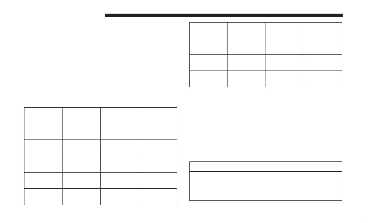
NOTE: Refer to the following chart for proper engine
shutdown.
Driving
Condition
Stop and
Go
Stop and
Turbo-
Load
charger
Tempera-
ture
Empty Cool Less than
Medium One
Idle Time
(min.) Be-
fore Engine
Shutdown
One
Go
Highway
Medium Warm Two
Speeds
City Traffic Maximum
Three
GCWR
Driving
Condition
Highway
Speeds
Uphill
Grade
Load
Maximum
GCWR
Maximum
GCWR
Turbo-
charger
Tempera-
ture
Hot Five
Idle Time
(min.) Be-
fore Engine
Shutdown
Four
Do Not Operate The Engine With Low Oil Pressure
If the low oil pressure warning light turns on while
driving, stop the vehicle and shut down the engine as soon
as possible. A chime will sound when the light turns on.
NOTE: Do not operate the vehicle until the cause is
corrected. This light does not show how much oil is in the
engine. The engine oil level must be checked under the
hood.
CAUTION!
If oil pressure falls to less than normal readings, shut
the engine off immediately. Failure to do so could
result in immediate and severe engine damage.
 Loading...