

Page 1
Page 2

If you are the rst registered retail owner of your vehicle, you
may obtain a complimentary printed copy of the Owner’s Manual,
®
Navigation/Uconnect
Manuals or Warranty Booklet by calling
1-866-726-4636 (U.S.) or 1-800-387-1143 (Canada) or by
contacting your dealer.
IMPORTANT
This User Guide is intended to familiarize you with the important
features of your vehicle. The DVD enclosed contains your Owner’s
Manual, Navigation/Uconnect
Warranty and Roadside Assistance (new vehicles purchased in the U.S.)
or Roadside Assistance (new vehicles purchased in Canada) in
electronic format. We hope you nd it useful. Replacement DVD
kits may be purchased by visiting www.techauthority.com.
Copyright 2016 FCA US LLC.
The driver’s primary responsibility is the safe operation of the vehicle. Driving while
distracted can result in loss of vehicle control, resulting in a collision and personal
injury. Chrysler Group LLC strongly recommends that the driver use extreme caution
when using any device or feature that may take their attention off the road. Use of any
electrical devices such as cell phones, computers, portable radios, vehicle navigation
or other devices by the driver while the vehicle is moving is dangerous and could
lead to a serious collision. Texting while driving is also dangerous and should never
be done while the vehicle is moving. If you find yourself unable to devote your full
attention to vehicle operation, pull off the road to a safe location and stop your
vehicle. Some States or Provinces prohibit the use of cellular telephones or texting
while driving. It is always the driver’s responsibility to comply with all local laws.
®
Manuals, Warranty Booklets, Tire
Page 3

TABLE OF CONTENTS
INTRODUCTION/WELCOME
WELCOME FROM FCA US LLC ......2
CONTROLS AT A GLANCE
DRIVER COCKPIT ...............4
INSTRUMENT CLUSTER ..........6
GETTING STARTED
KEYFOB ....................8
SEATBELT ................... 8
SUPPLEMENTAL RESTRAINT SYSTEM
(SRS) — AIR BAGS ..............9
FRONT SEATS ................10
HEATEDSEATS ............... 15
TELESCOPING STEERING COLUMN . . 16
OPERATING YOUR VEHICLE
ENGINE BREAK-IN
RECOMMENDATIONS ...........17
MANUAL CLIMATE CONTROLS ......18
TURN SIGNALS/HEADLIGHTS/
HIGH BEAMS LEVER ............19
INTERIOR LIGHTS .............20
WIPER/WASHER LEVER ..........21
ELECTRONIC SPEED CONTROL .....22
PARKSENSE
PARKVIEW
®
REAR PARK ASSIST . . . 24
®
REAR BACK-UP CAMERA . 25
ELECTRONICS
YOUR VEHICLE'S SOUND SYSTEM . . . 26
IDENTIFYING YOUR RADIO ........ 28
®
Uconnect
Uconnect
STEERING WHEEL AUDIO CONTROLS . 41
ELECTRONIC VEHICLE INFORMATION
CENTER (EVIC) ...............41
PROGRAMMABLE FEATURES ....... 42
POWER OUTLETS ..............43
RH3 ............... 29
®
5.0 ................31
UTILITY
TRAILER TOWING WEIGHTS (MAXIMUM
TRAILER WEIGHT RATINGS) ....... 44
RECREATIONAL TOWING (BEHIND
MOTORHOME, ETC.) ............44
DIESEL
DIESEL ENGINE BREAK-IN
RECOMMENDATIONS ...........46
DIESEL ENGINE STARTING
PROCEDURES ...............46
AUTOMATED MANUAL TRANSMISSION —
DIESEL ONLY ................48
EXHAUST REGENERATION ........ 52
COOL-DOWN IDLE CHART .........54
ADDING FUEL ................54
DIESEL EXHAUST FLUID ......... 55
WHAT TO DO IN EMERGENCIES
ROADSIDE ASSISTANCE .......... 58
INSTRUMENT CLUSTER WARNING
LIGHTS .................... 58
INSTRUMENT CLUSTER INDICATOR
LIGHTS .................... 62
IF YOUR ENGINE OVERHEATS ...... 63
JACKING AND TIRE CHANGING ..... 64
JUMP-STARTING ..............79
SHIFT LEVER OVERRIDE ......... 81
TOWING A DISABLED VEHICLE ..... 82
FREEING A STUCK VEHICLE .......82
EVENT DATA RECORDER (EDR) .....83
MAINTAINING YOUR VEHICLE
OPENING THE HOOD ...........84
ENGINE COMPARTMENT .........85
FLUID CAPACITIES —
GASOLINE ENGINE ............. 87
FLUIDS, LUBRICANTS AND GENUINE
PARTS — GASOLINE ENGINE ...... 87
FLUID CAPACITIES —
DIESEL ENGINE ...............89
FLUIDS, LUBRICANTS AND GENUINE
PARTS — DIESEL ENGINE ........ 89
MAINTENANCE SCHEDULE —
GASOLINE ENGINE ............. 92
MAINTENANCE SCHEDULE —
DIESEL ENGINE ...............97
FUSES ...................102
TIRE PRESSURES .............105
WHEEL AND WHEEL TRIM CARE . . . 106
BULBS ...................107
CUSTOMER ASSISTANCE
FCA US LLC CUSTOMER CENTER . . . 108
FCA CANADA INC. CUSTOMER
CENTER .................. 108
ASSISTANCE FOR THE HEARING
IMPAIRED ................. 108
PUBLICATIONS ORDERING .......108
REPORTING SAFETY DEFECTS IN
THEUNITEDSTATES ...........109
MOPAR® ACCESSORIES
AUTHENTIC ACCESSORIES BY
®
MOPAR
...................110
FAQ’s
FAQ’s .....................111
INDEX
....................112
Page 4

INTRODUCTION/WELCOME
WELCOME FROM FCA US LLC
Congratulations on selecting your new FCA US LLC vehicle. Be assured that it
represents precision workmanship, distinctive styling, and high quality - all essentials that are traditional to our vehicles.
Your new FCA US LLC vehicle has characteristics to enhance the driver's control
under some driving conditions. These are to assist the driver and are never a
substitute for attentive driving. They can never take the driver's place. Always drive
carefully.
Your new vehicle has many features for the comfort and convenience of you and your
passengers. Some of these should not be used when driving because they take your
eyes from the road or your attention from driving. Never text while driving or take your
eyes more than momentarily off the road.
This guide illustrates and describes the operation of features and equipment that are
either standard or optional on this vehicle. This guide may also include a description
of features and equipment that are no longer available or were not ordered on this
vehicle. Please disregard any features and equipment described in this guide that are
not available on this vehicle. FCA US LLC reserves the right to make changes in
design and specifications and/or make additions to or improvements to its products
without imposing any obligation upon itself to install them on products previously
manufactured.
This User Guide has been prepared to help you quickly become acquainted with the
important features of your vehicle. It contains most things you will need to operate
and maintain the vehicle, including emergency information.
The DVD includes a computer application containing detailed owner's information
which can be viewed on a personal computer or MAC computer. The multimedia DVD
also includes videos which can be played on any standard DVD player (including the
Uconnect
DVD operational information is located on the back of the DVD sleeve.
For complete owner information, refer to your Owner's Manual on the DVD in the owner’s
kit provided at the time of new vehicle purchase. For your convenience, the information
contained on the DVD may also be printed and saved for future reference.
FCA US LLC is committed to protecting our environment and natural resources. By
converting from paper to electronic delivery for the majority of the user information
for your vehicle, together we greatly reduce the demand for tree-based products and
lessen the stress on our environment.
®
Touchscreen Radios if equipped with DVD player capabilities). Additional
2
Page 5

INTRODUCTION/WELCOME
VEHICLES SOLD IN CANADA
With respect to any vehicles sold in Canada, the name FCA US LLC shall be deemed
to be deleted and the name FCA Canada Inc. used in substitution.
WARNING!
• Pedals that cannot move freely can cause loss of vehicle control and increase
the risk of serious personal injury.
• Always make sure that objects cannot fall into the driver foot well while the
vehicle is moving. Objects can become trapped under the brake pedal and
accelerator pedal causing a loss of vehicle control.
• Failure to properly follow floor mat installation or mounting can cause interference with the brake pedal and accelerator pedal operation causing loss of
control of the vehicle.
• Never leave children alone in a vehicle, or with access to an unlocked vehicle.
Allowing children to be in a vehicle unattended is dangerous for a number of
reasons. A child or others could be seriously or fatally injured. Children should
be warned not to touch the parking brake, brake pedal or the shift lever/
transmission gear selector.
• Do not leave the key fob in or near the vehicle, or in a location accessible to
children, and do not leave the ignition of a vehicle equipped with Keyless
Enter-N-Go in the ACC or ON/RUN mode. A child could operate power windows,
other controls, or move the vehicle.
• Never use the ‘PARK’ position as a substitute for the parking brake. Always
apply the parking brake fully when parked to guard against vehicle movement
and possible injury or damage.
• Refer to your Owner's Manual on the DVD for further details.
USE OF AFTERMARKET PRODUCTS (ELECTRONICS)
The use of aftermarket devices including cell phones, MP3 players, GPS systems, or
chargers may affect the performance of on-board wireless features including Keyless
Enter-N-Go™ and Remote Start range. If you are experiencing difficulties with any of
your wireless features, try disconnecting your aftermarket devices to see if the
situation improves. If your symptoms persist, please see an authorized dealer.
CHRYSLER, DODGE, JEEP, RAM TRUCK, SRT, ATF+4, MOPAR and Uconnect are
registered trademarks of FCA US LLC.
COPYRIGHT ©2016 FCA US LLC
3
Page 6

CONTROLS AT A GLANCE
DRIVER COCKPIT
1. Power Mirrors
2. Headlight Switch pg. 19
3. Instrument Cluster/Electronic Vehicle Information Center (EVIC) Display pg. 6
4. Wiper/Washer pg. 21
5. Transmission Shifter
6. Audio System (Touchscreen Radio Shown) pg. 26
7. Clip Board
8. Climate Controls pg. 18
9. Storage
10. Power Window Switch
11. Glove Compartment
4
Page 7

CONTROLS AT A GLANCE
12. Power Outlet pg. 43
13. USB Port (Charging Only)
14. Switch Panel
• Front Fog Lights
• Electronic Stability Control (ESC) OFF pg. 62
• Hazard Warning Switch
• Central Door Lock Switch
15. Storage — If Equipped
16. USB Port
17. Ignition Switch
18. Uconnect
19. Uconnect
20. Speed Control pg. 22
21. Hood Release pg. 35
22. Power Windows
®
Phone Controls pg. 35
®
Controls pg. 35
5
Page 8

CONTROLS AT A GLANCE
INSTRUMENT CLUSTER
1. Speedometer
2. Turn Signal Lights
3. Electronic Vehicle Information Center (EVIC)
4. Fuel Gauge
(See page 58 for Instrument Cluster Indicator Lights.)
6
Page 9

CONTROLS AT A GLANCE
5. Turn Signal Lights
6. Tachometer
7. Temperature Gauge
(See page 62 for Instrument Cluster Indicator Lights.)
7
Page 10
GETTING STARTED
KEY FOB
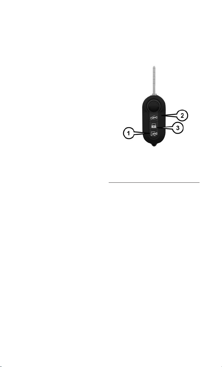
Locking And Unlocking The Doors
• Press the LOCK button once to lock all
the doors.
• Press the UNLOCK button once to
unlock the driver’s door only and twice
within five seconds to unlock all the
doors.
All doors can be programmed to unlock
on the first press of the UNLOCK button.
Refer to the Owner Manual on your DVD
for further information.
SEAT BELT
Be sure everyone in your vehicle is in a
seat and using a seat belt properly.
• Position the lap belt across your
thighs, below your abdomen. To remove slack in the lap portion, pull up a
bit on the shoulder belt. To loosen the lap belt if it is too tight, tilt the latch plate
and pull on the lap belt. A snug belt reduces the risk of sliding under the belt in
a collision.
• Position the shoulder belt on your chest so that it is comfortable and not resting
on your neck. The retractor will withdraw any slack in the belt.
A shoulder belt placed behind you will not protect you from injury during a collision.
You are more likely to hit your head in a collision if you do not wear your shoulder belt.
The lap and shoulder belt are meant to be used together.
A belt that is too loose will not protect you properly. In a sudden stop you could move
too far forward, increasing the possibility of injury. Wear your seat belt snugly.
A frayed or torn belt could rip apart in a collision and leave you with no protection.
Inspect the belt system periodically, checking for cuts, frays, or loose parts. Damaged
parts must be replaced immediately. Do not disassemble or modify the system. Seat
belt assemblies must be replaced after a collision if they have been damaged (bent
retractor, torn webbing, etc.).
The seat belts for both front seating positions are equipped with pretensioning
devices that are designed to remove slack from the seat belt in the event of a
collision.
A deployed pretensioner or a deployed air bag must be replaced immediately.
1 — Cargo Doors
2 — Unlock
3 — Lock
Key Fob
8
Page 11

GETTING STARTED
WARNING!
In a collision, you and your passengers can suffer much greater injuries if you are
not properly buckled up. You can strike the interior of your vehicle or other
passengers, or you can be thrown out of the vehicle. Always be sure you and others
in your vehicle are buckled up properly.
SUPPLEMENTAL RESTRAINT SYSTEM (SRS) — AIR BAGS
NOTE:
The Driver and Passenger Front Air Bags are certified to the new Federal regulations
for Front Air Bags.
• This vehicle is equipped with a driver and/or front passenger seat belt buckle
switch that detects whether the driver or front passenger seat belt is fastened.
• This vehicle is equipped with Supplemental Side Air Bag Inflatable Curtains
(SABIC) to protect the driver and front passengers sitting next to a window. The
vehicle SABIC air bags are located above the side windows and their covers are
labeled: AIRBAG. This vehicle is equipped with Supplemental Seat-Mounted Side
Air Bags (SAB) to provide enhanced protection for an occupant during a side
impact. The Supplemental Seat-Mounted Side Air Bags are located in the
outboard side of the front seats.
NOTE:
• Air Bag covers may not be obvious in the interior trim, but they will open during
air bag deployment.
• After any collision, the vehicle should be taken to an authorized dealer
immediately.
If the Air Bag Warning Light
driving, have the vehicle serviced by an authorized dealer immediately.
Refer to the Owner's Manual on the DVD for further details regarding the Supplemental Restraint System (SRS).
is not on during starting, stays on, or turns on while
9
Page 12

GETTING STARTED
WARNING!
• Relying on the air bags alone could lead to more severe injuries in a collision.
The air bags work with your seat belt to restrain you properly. In some collisions,
the air bags won't deploy at all. Always wear your seat belts even though you have
air bags.
• Being too close to the steering wheel or instrument panel during Front Air Bag
deployment could cause serious injury, including death. Air bags need room to
inflate. Sit back, comfortably extending your arms to reach the steering wheel or
instrument panel.
• Supplemental Side Air Bag Inflatable Curtains and Supplemental SeatMounted Side Air Bags need room to inflate. Do not lean against the door or
window. Sit upright in the center of the seat.
• Being too close to the Supplemental Side Air Bag Inflatable Curtain and/or
Seat-Mounted Side Air Bag during deployment could cause you to be severely
injured or killed.
• Do not drive your vehicle after the air bags have deployed. If you are involved in
another collision, the air bags will not be in place to protect you.
• After any collision, the vehicle should be taken to an authorized dealer
immediately.
FRONT SEATS
Forward/Rearward
The forward/rearward adjusting bar is located at the front of the seat near the
floor.
• Lift up on the adjusting bar and release it when the seat is at the desired
position. Then, using body pressure,
move forward and rearward on the seat
to be sure that the seat adjusters have
latched.
Lumbar Support
The lumbar control knob is located on the
rear upper outboard side of the driver’s
seatback.
• Rotate the control forward to increase
and rearward to decrease the desired
amount of lumbar support.
10
Forward/Rearward And Lumbar Controls
1 — Forward/Rearward Adjusting Bar
2 — Lumbar Knob
Page 13

Height Adjustment — Without Swivel Seat
The height adjusting levers are located on
the center outboard side of the seat.
• Lift up on the front lever to adjust the
front of the seat up or down.
• Lift up on the rear lever to adjust the
rear of the seat up or down.
1 — Front Height Adjusting Lever
2 — Rear Height Adjusting Lever
Height Adjustment — With Swivel Seat
GETTING STARTED
Height Adjusting Levers
The height adjusting knobs are located
on the center outboard side of the seat.
• Rotate the front knob to adjust the
front of the seat up or down.
• Rotate the rear knob to adjust the rear
of the seat up or down.
Height Adjustment Knobs
1 — Front Height Adjusting Knob
2 — Rear Height Adjusting Knob
11
Page 14

GETTING STARTED
Recliner — Without Swivel Seat
The recliner knob is located on the rear
outboard side of the seat.
• To recline the seatback, lean back,
rotate the recliner knob rearward to
position the seatback as desired.
• To return the seatback to its normal
upright position, lean forward and rotate the recliner knob forward until the
seatback is in the upright position.
Recliner — With Swivel Seat
The recliner lever is located at the lower
front outboard side of the seat.
• To recline the seatback, lean forward
slightly, pull the lever outward, lean
back to the desired position and release the lever.
• To return the seatback to its normal
upright position, lean forward and pull
the lever outward. Release the lever
once the seatback is in the upright
position.
Recliner Knob
12
Recliner Lever
Page 15

Air Seat Adjustment
The seat is equipped with a mechanical
spring system and hydraulic shock absorber to ensure maximum comfort and
safety. The system of springs also effectively absorbs impact from uneven road
surfaces.
• Use the weight adjustment knob to set
the required setting based on body
weight, with settings between 88 lbs
(40 kg) and 286 lbs (130 kg).
Swivel Seat Adjustment
The swivel seat lever is located at the
lower front inboard side of the seat.
• The seat may be turned 180° toward
the seat on the opposite side and approximately 35° toward the door.
• The seat may be locked in the driving
position or at the 180° position.
• To swivel the seat, pull the swivel seat
lever outward, turn the seat to the
desired position and release the lever.
GETTING STARTED
1 — Weight Adjustment Knob
Swivel Seat Lever
13
Page 16

GETTING STARTED
Armrest Height Adjustment
The height adjusting rotating knob is located underneath the front of the drivers
and passengers armrest.
• Rotate the knob to adjust the armrest
up or down.
1 — Armrest Height Adjustment Knob
WARNING!
• Adjusting a seat while the vehicle is moving is dangerous. The sudden movement of the seat could cause you to lose control. The seat belt might not be
properly adjusted, and you could be severely injured or killed. Only adjust a seat
while the vehicle is parked.
• Do not ride with the seatback reclined so that the seat belt is no longer resting
against your chest. In a collision, you could slide under the seat belt and be
severely injured or killed. Use the recliner only when the vehicle is parked.
• Be certain that the seat cushion is locked securely into position before using the
seat. Otherwise, the seat will not provide the proper stability for passengers. An
improperly latched seat cushion could cause serious injury.
14
Page 17

GETTING STARTED
HEATED SEATS
Front Heated Seats
The controls for the front heated seats are
located on the lower outboard side of the
seat.
• Press the switch once to turn on the
heated seats.
• Press the switch a second time to shut
the heating elements off.
1 — Heated Seat Switch
WARNING!
• Persons who are unable to feel pain to the skin because of advanced age,
chronic illness, diabetes, spinal cord injury, medication, alcohol use, exhaustion
or other physical conditions must exercise care when using the seat heater. It
may cause burns even at low temperatures, especially if used for long periods of
time.
• Do not place anything on the seat that insulates against heat, such as a blanket
or cushion. This may cause the seat heater to overheat. Sitting in a seat that has
been overheated could cause serious burns due to the increased surface
temperature of the seat.
15
Page 18

GETTING STARTED
TELESCOPING STEERING COLUMN
The telescoping control handle is located
below the steering wheel at the end of the
steering column.
• To unlock the steering column, pull
the control handle up.
• To lengthen or shorten the steering
column, pull the steering wheel outward or push it inward as desired.
• To lock the steering column in position, push the control handle down
until fully engaged.
1 — Telescoping Control Handle
16
Page 19

OPERATING YOUR VEHICLE
ENGINE BREAK-IN RECOMMENDATIONS
A long break-in period is not required for the engine and drivetrain (transmission and
axle) in your vehicle.
Drive moderately during the first 300 miles (500 km). After the initial 60 miles
(100 km), speeds up to 50 or 55 mph (80 or 90 km/h) are desirable.
While cruising, brief full-throttle acceleration within the limits of local traffic laws
contributes to a good break-in. Wide-open throttle acceleration in low gear can be
detrimental and should be avoided.
The engine oil installed in the engine at the factory is a high-quality energy
conserving type lubricant. Oil changes should be consistent with anticipated climate
conditions under which vehicle operations will occur. For the recommended viscosity
and quality grades, refer to “Maintaining Your Vehicle.”
NOTE:
A new engine may consume some oil during its first few thousand miles (kilometers)
of operation. This should be considered a normal part of the break-in and not
interpreted as an indication of an engine problem or malfunction.
CAUTION!
Never use Non-Detergent Oil or Straight Mineral Oil in the engine or damage may
result.
17
Page 20

OPERATING YOUR VEHICLE
MANUAL CLIMATE CONTROLS
Manual Climate Controls
1 — Rotate Blower Control 4 — Push A/C Button
2 — Push Air Recirculation Button 5 — Rotate Mode Control
3 — Rotate Temperature Control 6 — Push Rear Window Defroster
Air Recirculation
• Use Recirculation for maximum A/C operation.
• For window defogging, turn the Recirculation button off.
• Recirculation is not allowed in defrost.
• Recirculation is allowed in floor mode and defrost/floor (mix modes) for approximately five minutes.
Button
Heated Mirrors
The mirrors are heated to melt frost or ice. This feature is activated whenever you turn
on the rear window defroster.
18
Page 21

OPERATING YOUR VEHICLE
TURN SIGNALS/HEADLIGHTS/HIGH BEAMS LEVER
Turn Signal Headlight Lever
1 — High Beams
2 — Headlights
3 — Turn Signals
Turn Signals/Lane Change Assist
• Tap the lever up or down once and the turn signal (right or left) will flash four times
and automatically turn off.
Headlights/Parking Lights
• Rotate the end of the lever to the first detent for parking lights and headlight
operation.
NOTE:
The ignition switch must be in the ON/RUN position for the headlights to operate.
High Beam Operation
• Pull the multifunction lever toward you to switch the headlights to high beam.
• Pull the multifunction lever a second time to switch the headlights back to low
beam.
A high beam symbol will illuminate in the cluster to indicate the high beams are on.
NOTE:
For safe driving, turn off the high beams when oncoming traffic is present to prevent
headlight glare and as a courtesy to other motorists.
19
Page 22

OPERATING YOUR VEHICLE
INTERIOR LIGHTS
Map/Dome Lights
These lights are mounted between the
sun visors on the overhead console. Each
light is turned on by pressing the corresponding switch.
Left Switch
• Press the left switch to the left to turn
OFF the auto dome lights. The dome
lights will not automatically turn on
when a door is opened.
• Press the left switch to the right to
turn ON the dome lights.
Right Switch
• Press the right switch to the left to
turn ON the left map light.
• Press the right switch to the right to
turn ON the right map light.
Dimmer Controls
1 — Auto/Off 3 — Left Map
2 — Dome 4 — Right Map
Map/Dome Lights
The dimmer controls are located on the
left side of the instrument panel below
the instrument cluster.
• Press and release the UP
to increase the brightness of the instrument panel lights.
• Press and release the DOWN
button to decrease the brightness of
the instrument panel lights.
button
Cargo Lamp
The Rear Cargo Lamp is located at the
upper rear cargo area above the rear
doors.
Your vehicle may be equipped with a Side
Cargo Lamp located at the upper rear area of the passenger side sliding door opening.
The Cargo Lamps can be set to three different positions (Off/Right Position, Center
Position, On/Left Position).
20
Dimmer Controls
Page 23

OPERATING YOUR VEHICLE
• Press the Cargo Lamp lens to the right from its center position and the lamp is
always off.
• Leave the Cargo Lamp lens in the center position, and the lamp is turned on and
off when the sliding doors or rear doors are opened or closed.
• Press the Cargo Lamp lens to the left from its center position and the lamp is
always on.
WIPER/WASHER LEVER
Wiper Washer Lever
1 — Mist
2 — Intermittent, Low And High
3 — Washer
The Wiper/Washer Lever is located on the right side of the steering column.
Front Wipers
Intermittent, Low And High Operation
• Push the lever downward to the first detent and rotate the center ring to use one
of the four intermittent wiper settings.
• Push the lever downward to the second detent for low wiper operation.
• Push the lever downward to the third detent for high wiper operation.
Washer Operation
• Pull the lever toward you and hold for as long as spray is desired.
Mist
• Push the lever upward and release when a single wipe is desired.
21
Page 24

OPERATING YOUR VEHICLE
NOTE:
The mist feature does not activate the washer pump; therefore, no washer fluid is
sprayed on the windshield. The wash function must be activated to spray the
windshield with washer fluid.
ELECTRONIC SPEED CONTROL
Electronic Speed Control Lever
1 — Set/Accel
2 — On/Off
3 — Resume
4 — Decel
The Electronic Speed Control lever is located on the left side of the steering column.
Cruise ON/OFF
• Rotate the center ring upward on the electronic speed control lever to turn the
system ON.
The cruise symbol
Control is on.
• To turn the system OFF, rotate the center ring upward a second time.
will appear on the instrument cluster to indicate the Speed
Set
• With the Speed Control on, push the electronic speed control lever upward SET (+)
and release to set a desired speed.
22
Page 25

OPERATING YOUR VEHICLE
Accel/Decel
To Increase Speed
• When the Electronic Speed Control is set, you can increase speed by tapping the
Speed Control lever up (+).
The speed increment shown is dependant on the speed of U.S. (mph) or Metric
(km/h) units:
U.S. Speed (mph)
• Tapping the Speed Control lever up (+) once will result in a 1 mph increase in
set speed. Each subsequent tap of the lever results in an increase of 1 mph.
• If the lever is continually help up, the set speed will continue to increase until
the lever is released, then the new set speed will be established.
Metric Speed (km/h)
• Tapping the Speed Control lever up (+) once will result i n a 2 km/h increase in
set speed. Each subsequent tap of the lever results in an increase of 2 km/h.
• If the lever is continually help up, the set speed will continue to increase until
the lever is released, then the new set speed will be established.
To Decrease Speed
• When the Electronic Speed Control is set, you can decrease speed by tapping the
Speed Control lever down (-).
The speed decrement shown is dependant on the speed of U.S. (mph) or Metric
(km/h) units:
U.S. Speed (mph)
• Tapping the Speed Control lever down (-) once will result in a 1 mph decrease
in set speed. Each subsequent tap of the lever results in a decrease of 1 mph.
• If the lever is continually held down, the set speed will continue to decrease
until the lever is released, then the new set speed will be established.
Metric Speed (km/h)
• Tapping the Speed Control lever down (-) once will result in a 2 km/h decrease
in set speed. Each subsequent tap of the lever results in a decrease of 2 km/h.
• If the lever is continually held down, the set speed will continue to decrease
until the lever is released, then the new set speed will be established.
Resume
• To resume a previously set speed, push the RES button and release.
Cancel
• A soft tap on the brake pedal, pushing the RES button, or normal brake pressure
while slowing the vehicle will deactivate the Speed Control without erasing the set
speed memory.
Rotating the center ring upward to turn the system OFF or turning the ignition switch
OFF erases the set speed memory.
23
Page 26

OPERATING YOUR VEHICLE
WARNING!
• Leaving the Electronic Speed Control system on when not in use is dangerous.
You could accidentally set the system or cause it to go faster than you want. You
could lose control and have a collision. Always leave the Electronic Speed
Control system off when you are not using it.
• Electronic Speed Control can be dangerous where the system cannot maintain
a constant speed. Your vehicle could go too fast for the conditions, and you
could lose control. A collision could be the result. Do not use Electronic Speed
Control in heavy traffic or on roads that are winding, icy, snow-covered or
slippery.
PARKSENSE® REAR PARK ASSIST
If an object is detected behind the rear bumper while the vehicle is in REVERSE, a
chime sounds. The chime rate changes depending on the distance of the object,
getting faster as the object gets closer to the bumper. The chime sounds off
continuously when the distance between the vehicle and the obstacle is less than
12 inches (30 cm).
24
Page 27

OPERATING YOUR VEHICLE
PARKVIEW® REAR BACK-UP CAMERA
You can see an on-screen image of the rear of your vehicle whenever the shift lever is
put into REVERSE. The ParkView
touchscreen display located on the center stack of the instrument panel.
NOTE:
If the touchscreen display appears foggy, clean the camera lens located on the top
rear of the vehicle below the center light.
®
Rear Back-Up Camera image is displayed on the
WARNING!
Drivers must be careful when backing up; even when using the ParkView®Rear
Back-Up Camera. Always check carefully behind your vehicle, and be sure to
check for pedestrians, animals, other vehicles, obstructions, or blind spots before
backing up. You must continue to pay attention while backing up. Failure to do so
can result in serious injury or death.
25
Page 28

ELECTRONICS
YOUR VEHICLE'S SOUND SYSTEM
1. Uconnect®Phone Mute Button
®
2. Uconnect
3. Steering Wheel Audio Controls (Right) pg. 41
4. Phone Hang Up Button
5. Uconnect
6. USB/Audio Jack pg. 34
7. Volume Knob/Audio Mute Button pg. 31
26
Phone Button pg. 35
®
Voice Command Button pg. 38
Page 29

ELECTRONICS
8. Eject Button pg. 31
9. CD Slot pg. 34
®
10. Uconnect
11. Display On/Off Button
12. Tune/Scroll Knob/Browse/Enter Button
13. Front Power Outlet/Cigar Lighter pg. 43
14. USB Port (Charging Only)
Radio pg. 31
27
Page 30

ELECTRONICS
IDENTIFYING YOUR RADIO
Uconnect® RH3
• Single Din Mono-Chromatic
• Manual Three-Knob Climate Control
Uconnect® 5.0
• 5” Color Touchscreen
• Manual Three-Knob Climate Control
Uconnect® RH3
28
Uconnect® 5.0
Page 31
Uconnect® RH3
ELECTRONICS
Uconnect® RH3
Enable Or Disable Clock
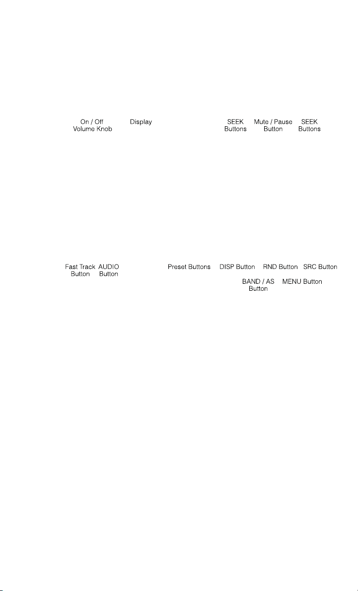
1. Press the DISP button for more than two seconds to enable or disable the Clock.
2. When this function is enabled, the display shows the message "CLK ON" and the
clock is displayed whenever the ignition is On, even with the radio Off. In
10 seconds if no radio key is pressed, the display returns to the clock.
3. When this function is disabled, the message "CLK OFF" is displayed on the radio
display.
NOTE:
This procedure sets the time on the radio clock ONLY. To set the time in the
Electronic Vehicle Information Center, please refer to the section titled Electronic
Vehicle Information Center (EVIC) in this manual.
29
Page 32

ELECTRONICS
Equalizer, Balance And Fade
• Adjust Equalizer of bass and treble
• Balance left/right (BALANCE) and front/rear (FADER)
• Strengthen sound (loudness)
Equalization
• Press the AUDIO button for more than two seconds to access equalization: FLAT,
ROCK, CLASSIC, POP, VOCAL, JAZZ, USER or FLAT.
• Pressing AUDIO more than once changes equalization options. If this key is not
pressed again for five seconds or the ROTARY is pressed, the display returns to the
previously selected view and the adjustments made is saved.
Balance, Fade, Loudness, Bass And Treble
• Pressing the AUDIO button for less than two seconds accesses an audio function.
• Pressing AUDIO more than once accesses other functions (e.g. Bass, Treble,
Balance, Fader, Loudness and Bass). If this key is not pressed again for five
seconds or the ROTARY is pressed, the display returns to the previously selected
view and the adjustments made is saved. The Bass and Treble functions are only
accessible if the USER EQ has been selected.
Radio Operation
Seek Up/Seek Down
• Press the “double arrows” to the left for less than two seconds to seek down to the
next station. Press the “double arrows” to the right for less than two seconds to
seek up to the next station.
Radio Presets
• When you are receiving a station that you wish to commit into memory, press and
hold the desired numbered memory button (1 through 6) for more than three
seconds.
USB/MP3 Audio Jack
• USB/iPod®Mode is entered by inserting a USB Jump Drive or an iPod®cable into
the USB port.
WARNING!
To remove devices connected to the USB port, first select the other audio source.
Failure to follow this procedure can cause damage to the connected device. Due
to the extensive range of makes and models of storage devices available on the
market, not all devices have compatibility required for proper functioning of Car
Radios. Use only quality USB devices.
30
Page 33

ELECTRONICS
Forward/Reverse Folder
• Press the button memory 1 to advance to the first track of the next folder that
contains audio files. Press the button memory 2 to go back to the first track in the
previous folder that contains audio files. When this operation is performed, the
display shows the name of the selected folder.
Song Shuffle
• Press the RND to "shuffle songs". When enabled, "RND ON" is on the displayed for
two seconds. After this period the display reverts to the previous view. When this
button is pressed again, the function is disabled, and the display indicates "RND
OFF" for two seconds. After this period the display reverts to the view previously
selected.
Uconnect® 5.0
Uconnect® 5.0
Clock Setting
1. To start the clock setting procedure, press the SETTINGS hard-key on the right
side of the display, then “Clock & Date” soft-key, and then “Set Time & Format”
soft-key. Select the up or down arrows as appropriate.
2. Touch the “Up or Down arrows” to adjust the hours or minutes, next select the AM
or PM soft-key. You can also select 12hr or 24hr format by touching the desired
soft-key.
31
Page 34

ELECTRONICS
3. Once the time is set press the “Done” or “back arrow” soft-key to exit the time
screen.
NOTE:
Once the time has been set on the radio, the time will also appear in the Electronic
Vehicle Information Center (EVIC).
Equalizer, Balance And Fade
1. Press the SETTING hard-key on the right side of the display.
2. Scroll down and touch the “Audio” soft-key to open the Audio menu.
3. The Audio Menu shows the following options for you to customize your audio
settings.
Equalizer
• Touch the “Equalizer” soft-key to adjust the Bass, Mid and Treble. Use the + or -
soft-key to adjust the equalizer to your desired settings.
Balance/Fade
• Touch the “Balance/Fade” soft-key to adjust the sound from the speakers. Use the
“arrow” soft-keys to adjust the sound level from the front and rear or right and left
side speakers. Touch the Center “C” soft-key to reset the balance and fade to the
factory setting.
Speed Adjusted Volume
• Touch the “Speed Adjusted Volume” soft-key to select between OFF, 1, 2 or 3.
This decreases the radio volume relative to a decrease in vehicle speed.
Loudness
• Touch the “Loudness” soft-key to select the Loudness feature. When this feature
is activated it improves sound quality at lower volumes.
Surround Sound
• Touch the “Surround Sound” soft-key, select On or Off followed by touching the
“back arrow” soft-key. When this feature is activated, it provides simulated
surround sound mode.
Radio Off Delay
• Touch the “Radio Off Delay” soft-key and select0–20minutes followed by
touching “Done” or the “back arrow” soft-key. When this feature is activated, the
radio remains on for the selected amount of time while the engine is off.
Auto-On Radio
• Touch the “Auto-On Radio” soft-key, select On, Off, or Recall Last followed by
touching “Done” or the “back arrow” soft-key. When this feature is activated, the
radio automatically turns on when the vehicle is in run or recalls whether it was on
or off at last ignition off.
32
Page 35
ELECTRONICS
Radio Operation
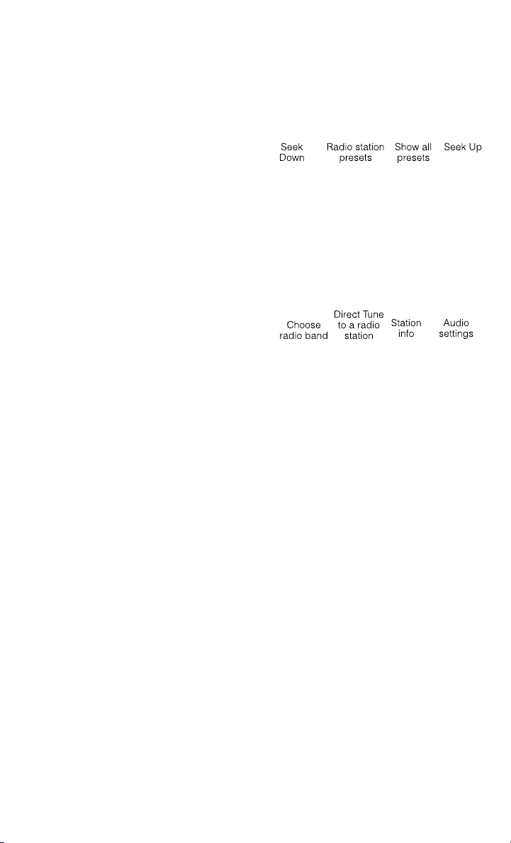
Seek Up/Down Buttons
• Press to seek through radio stations in
AM, FM or SXM bands.
• Hold either button to bypass stations
without stopping.
Store Radio Presets
• When you are receiving a station that
you wish to commit into memory,
touch and hold the desired numbered
soft-key for more than two seconds, or
until you hear a confirmation beep.
• The Radio stores up to 12 presets in
each of the Radio modes. Four presets
are visible at the top of the radio
screen. Touching the “all” soft-key on
the radio home screen displays all of the preset stations for that mode.
SiriusXM Premier Over 160 Channels
Get every channel available on your satellite radio, and enjoy all you want, all in one
place. Hear commercial-free music plus sports, news, talk and entertainment. Get all
the premium programming, including Howard Stern, every NFL game, Oprah Radio
every MLB
channels, including SiriusXM Latino, a selection of channels dedicated to Spanish
language programming.
• To access SiriusXM Satellite Radio, press the “RADIO” hard-key and then the SXM
SiriusXM services require subscriptions, sold separately after the 12-month trial
included with the new vehicle purchase. If you decide to continue your service at the
end of your trial subscription, the plan you choose will automatically renew and bill at
then-current rates until you call SiriusXM at 1-866-635-2349 for U.S. residents and
1-888-539-7474 for Canadian residents to cancel. U.S. residents see SiriusXM Customer
Agreement for complete terms at www.siriusxm.com. Canadian residents should visit
www.sirius.ca for complete terms. All fees and programming subject to change. Our
satellite service is available only to those at least 18 and older in the 48 contiguous
USA and D.C. Our Sirius satellite service is also available in PR (with coverage
limitations). Our Internet radio service is available throughout our satellite service
area and in AK. © 2014 Sirius XM Radio Inc. Sirius, XM and all related marks and
logos are trademarks of Sirius XM Radio Inc.
soft-key.
®
and NHL®game, every NASCAR®race and more. And get 20+ Xtra
Uconnect® 5.0 Radio
®
,
33
Page 36

ELECTRONICS
Disc Operation
• CD/Disc Mode is entered by either inserting a CD/Disc or by touching the MEDIA
button located below the display. Once in Media Mode, select Disc.
• Gently insert one CD into the CD player with the CD label facing up.
Seek Up/Down Buttons
• Press to seek through Disc tracks.
• Hold either button to bypass tracks without stopping.
Browse
• Touch the “browse” soft-key to scroll through and select a desired track on the
Disc. Touch the “exit” soft-key if you wish to cancel the browse function.
USB/Audio Jack (AUX)/Bluetooth® Operation
USB/iPod®The USB Input and Auxiliary Jack is located on the instrument panel left
of the radio (driver’s lower right).
• USB/iPod
inserting a USB Jump Drive or an
iPod
pressing the MEDIA hard-key located
below the display. Once in Media
Mode, touch the “Source” soft-key
and select USB/iPod
• Press the MEDIA hard-key, touch the
“Source” soft-key then select
USB/iPod
USB device. If the device is connected, music from your portable device plays through the vehicle's
speakers.
Audio Jack (AUX)
The AUX jack allows a portable device, such as an MP3 player or an iPod
plugged into the radio and utilize the vehicle’s audio system. Using a 3.5 mm audio
jack plugged into the AUX jack will amplify the source and play the music through the
vehicle speakers.
• Press the MEDIA hard-key, touch the “Source” soft-key then select AUX to change
the mode to the AUX device. If the device is connected in play mode, music from
your portable device will play through the vehicle's speakers.
• The functions of the portable device are controlled using the device. However, the
volume may be controlled using the radio or portable device.
®
Mode is entered by either
®
cable into the USB port or by
®
®
to change the mode to the
USB/Audio Jack
®
,tobe
34
Page 37

ELECTRONICS
Bluetooth®
If using a Bluetooth
through your vehicle's sound system.
• Press the MEDIA hard-key, touch the “Source” soft-key then select Bluetooth
change the mode to Bluetooth
device plays through the vehicle's speakers.
Uconnect® 5.0 Available Media Hubs
S = Standard Equipment
Navigation
If your vehicle is equipped with Navigation, there will be a NAV hard-key in place of
the COMPASS hard-key. See your Uconnect
www.ramtrucks.com/promaster for additional information.
Uconnect® Phone (Bluetooth® HANDS FREE CALLING)
• If the Uconnect®Phone Button exists on your steering wheel, then you have
the Uconnect
• The Uconnect
tions system with Voice Command Capability (see Voice Command section).
• The Uconnect
using simple voice commands or using screen soft-keys.
• Refer to the “Understand The Features Of Your Vehicle” section of your vehicle's
Owner's Manual on the DVD for further details.
NOTE:
The Uconnect
Hands-Free Profile, Version 1.0 or higher. For Uconnect®Customer Support: U.S.
residents visit www.UconnectPhone.com or call 1-888-242-6342. Canadian Residents visit www.UconnectPhone.com or call 1-800-465–2001 (English) or
1-800-387-9983 (French).
®
- equipped device, you may also be able to stream music
®
. If the device is paired, music from your portable
Uconnect®5.0
®
Phone features.
®
Phone is a voice-activated, hands-free, in-vehicle communica-
®
Phone allows you to dial a phone number with your mobile phone
®
Phone requires a mobile phone equipped with the Bluetooth
Media Hub (USB, AUX Ports)
S
®
Supplement manual or
®
to
®
Pairing A Phone
• To use the Uconnect®Phone feature, you must first pair your Bluetooth®phone
with the Uconnect
Start Pairing Procedure On Mobile Phone
• Search for available devices on your Bluetooth
usually within Settings or Options under “Bluetooth.” See your mobile phone’s
manual for details.
®
system.
®
enabled mobile phone. This is
35
Page 38

ELECTRONICS
• When your phone finds the system, select “Uconnect” as the paired device. You
may be prompted by your phone to download the phonebook. This is so you can
make calls by saying the name of your contact (PBAP-Phone Book Access Profile).
Start Pairing Procedure On The Radio
• Press the PHONE hard-key then press “Yes” to start searching for the mobile
phone.
®
• Uconnect
connecting.
Complete The Pairing Procedure
• When prompted on the phone, verify with radio password shown on the Uconnect
Screen.
• If your phone asks you to accept a connection request from Uconnect
“Yes.” If available, check the box telling it not to ask again – that way your phone
automatically connects each time you start the vehicle.
Select The Mobile Phone's Priority Level
• When the pairing process has successfully completed, the system prompts you to
choose whether or not this is your favorite phone. Selecting “Yes” makes this
phone the highest priority. This phone takes precedence over other paired phones
within range. Only one phone can be paired at a time.
• You are now ready to make hands-free calls. Press the Uconnect
your steering wheel to begin.
Phone will display an “In progress” screen while the system is
®
, select
®
Phone button on
®
Making A Phone Call
• Push the Uconnect®Phone button .
• After the BEEP, say “dial” then the number (or “call” then the name as listed in
your phone; see Phonebook).
NOTE:
You can also initiate a call by using the touchscreen on the Phone main screen.
Receiving A Call — Accept (And End)
• When an incoming call rings/is announced on Uconnect®, press the Phone button
.
• To end a call, press the Hang Up or Phone button.
Mute (Or Unmute) Microphone During Call
• During a call, touch the “Mute” soft-key on the Phone main screen to mute and
unmute the microphone.
Transfer Ongoing Call Between Handset And Vehicle
• During an on-going call, press the “Transfer” button on the main Phone screen to
transfer an on-going call between the handset and the vehicle.
36
Page 39

ELECTRONICS
Common Phone Commands (Examples)
• “Call John Smith”
• “Call John Smith mobile”
• “Dial 1 248 555 1212”
• “Call Emergency”
• “Call Towing Assistance”
• “Redial”
Phonebook
Uconnect®radios automatically downloads your phonebook from your paired phone,
if this feature is supported by your phone. Entries are updated each time that the
phone is connected. If your phone book entries do not appear, check the settings on
your phone. Some phones require you to enable this feature manually.
• Your phonebook can be browsed on your radio screen, but editing can only be done
on your phone. To browse, press the “Phone” button on the touchscreen, then the
“Phonebook” button on the touchscreen.
Favorite phonebook entries can be saved as Favorites for quicker access. Favorites
are shown at the top of your main phone screen.
Voice Command Tips
• Using the complete name of a contact, as stored in your phonebook, (e.g. Call
John Doe vs. Call John) results in greater system accuracy.
• You can ‘chain’ commands together for faster results. Say “Call John Doe,
mobile,” for example.
• If you are listening to available voice command options, you do not have to listen
to the entire list. When you hear the command that you need, press the
button on the steering wheel, wait for the beep and say your command.
Changing The Volume
• Use the radio ON/OFF VOLUME rotary knob to adjust the volume to a comfortable
level while the Uconnect
Uconnect
NOTE:
To access help, press either the Uconnect
Voice Command button and say "Help." Touch or push either or
button and say "Cancel" to cancel the help session.
®
is different than the audio system.
®
system is speaking. Please note the volume setting for
®
Phone button or the Uconnect
37
®
Page 40
ELECTRONICS
Voice Text Reply
• Uconnect®Phone can read or send new text messages on your mobile phone.
• Your mobile phone must be MAP (Message Access Profile) compatible to support
SMS via Bluetooth
phone is not compatible with SMS messaging over Bluetooth
button is greyed out and the feature is not available for use.
NOTE:
For mobile phone compatibility and pairing instructions, please visit
www.UconnectPhone.com
• Any voice commanded system should be used only in safe driving conditions
following applicable laws regarding phone use. Your attention should be focused
on safely operating the vehicle. Failure to do so may result in a collision causing
you and others to be severely injured or killed.
• In an emergency, to use Uconnect
• turned on,
• paired to Uconnect
• and have network coverage.
VOICE COMMAND QUICK REFERENCE
Uconnect® 5.0 Voice Command
• If the Uconnect Voice Command button exists on your steering wheel, you
have the Voice Command feature, which is optimized for the driver. The Voice
Command feature lets you keep your hands on the wheel, and your eyes on the
road.
• When you press the Voice Command
you hear a beep. After the beep, give your command. If you do not know what
commands to say, you can say “help” and the system provides options to you. If
you ever wish to interrupt the system while it lists options, press the Voice
Command
NOTE:
All phone oriented voice commands are accessible by first pressing the Phone Pick
Up button, not the Voice Command button. To end a call, simply press the Phone
Hang Up button. In some vehicles, the Phone Pickup button serves the dual purpose
of ending calls as well.
®
to use this feature. If the Uconnect®Phone determines your
®
the “Messaging”
WARNING!
®
Phone, your mobile phone must be:
®
Phone,
button located on the steering wheel,
button, and after the beep, say your command.
38
Page 41
ELECTRONICS
Voice Command (VR) User TIPs
®
• To hear available commands, press the Uconnect
say “Help.” You hear available commands for the menu displayed.
• At any time, you can say the words “Cancel” or “Help.” These commands are
universal and can be used from virtually any menu. All other specific commands
can be used depending upon the active application.
• You can interrupt the system prompts at any time by pressing the Uconnect
Command button while the system is speaking. After the beep, you can say a
command.
• You can ‘chain’ commands together for faster results. Say “Call Joe Doe mobile,”
for example.
• For best performance, adjust the rearview mirror to provide at least ½ inch (1 cm)
gap between the overhead console (if equipped) and the mirror. This creates an
unobstructed path to the microphone on the overhead console.
• Always wait for the beep before speaking.
• Speak normally, without pausing, just as you would speak to a person sitting a few
feet/meters away from you.
• Ensure that no one other than you is speaking during a Voice Command period.
Steering Wheel Buttons
• You can control many of your radio features using your voice. Press either the VR
or Phone Pick Up button on your steering wheel.
Steering Wheel
Types of Voice
Commands
Available
Buttons to
Press:
Uconnect
Voice Com-
mand (VR) But-
ton
Uconnect
Phone Button
Radio Mode Media Mode Phone Mode
®
AM/FM & Sat-
ellite Band
Control
®
--
Voice Command button and
Media Devices
Control
GENERAL
Call Initiation,
Call Manage-
ment, Pre-
formatted Voice
Text Reply
®
Voice
-
39
Page 42

ELECTRONICS
Voice Command Examples – Uconnect® 5.0
While In: Voice Command Example:
GENERAL
“Cancel”
specific to current need)
“Repeat”
set 5)
time Favorites)
other)
“Redial”
name in address book)
sages:
“Yes.”
“No.”
“Okay.”
“I can’t talk right now.”
“Call me.”
“I’ll call you later.”
“I’m on my way.”
“Thanks.”
“I’ll be late.”
“Stuck in traffic.”
“Start without me.”
“Where are you?”
“Are you there yet?”
“I need directions.”
“I’m lost.”
“See you later.”
Anytime
AM/FM
Satellite Band Control
Media Devices Control (Functionality is
dependent on compatibility between de-
Call Initiation (Requires that phone has
been Bluetooth
Voice Text Reply (Radio audibly recognizes
these 18 pre-formatted SMS messages as
vices and radio)
®
paired with radio)
Call Management
you speak)
“Help” (to listen to suggested commands
RADIO
“Tune to AM950,” “Tune to 95.5FM (pre-
“Tune to Satellite Channel 80's on 8,”
Tune to Satellite Channel 32 (preset 4)
MEDIA
“Browse” (show) “artist” (albums, music)
“Show paired phones” (devices)
“Play song – Maple Leaf Rag” (artist -
Scott Joplin, genre - rock, album - Rag-
PHONE
“Dial 123-456-7890” (phone number)
“Call John Smith mobile” (home, office,
“Show outgoing” (recent) “calls”
“Search for John Smith” (any contact
“Show (display list) contacts”
Forward one of 18 pre-formatted SMS
messages to incoming calls/text mes-
“I will be <number> minutes late.”
“See you in <number> minutes.”
40
Page 43
ELECTRONICS
STEERING WHEEL AUDIO CONTROLS
The steering wheel audio controls are located on the front surface of the steering
wheel.
Right Switch
• Press the switch up or down to search
for the next listenable station.
Left Switch
• Press the switch up or down to increase or decrease the volume.
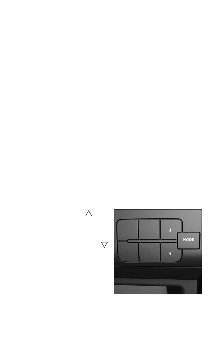
ELECTRONIC VEHICLE INFORMATION CENTER (EVIC)
The EVIC features a driver interactive display that is located in the instrument
cluster. Pressing the controls on the left side of the steering column allows the driver
to select vehicle information and Personal Settings. For additional information, refer
to “Programmable Features” in this guide.
• Press and release the UP
to scroll upward through the main
menus (Menu, Outside Temperature
Display, Trip Functions, Date, Time)
and sub menus.
• Press and release the DOWN
button to scroll downward through the
main menus and sub menus.
• Press and release the MODE button for
access to main menus, sub menus or
to select a personal setting in the
setup menu. Press and hold the MODE
button for two seconds to reset features.
• Press and hold the MODE button for
two seconds to reset displayed/
selected features that can be reset.
button
EVIC Controls
41
Page 44

ELECTRONICS
PROGRAMMABLE FEATURES
Programmable Features
The EVIC can be used to view or change the following settings:
• Press the MODE button to access the menu items then press the UP
button to view the menu items listed below. Press the MODE button to enter
the sub menus. Scroll through the settings using the UP or DOWN buttons.
•Menu •Time
• Outside Temperature Display • Date
• Trip Functions
Uconnect® Customer Programmable Features
The Uconnect®system allows you to access Customer Programmable feature
settings such as Display, Clock & Date, Safety/Assistance, Lights, Doors & Locks,
Audio, Phone/Bluetooth
soft-keys.
• Press the SETTINGS hard-key located on the right side of the display. When
making a selection, scroll up or down until the preferred setting is highlighted,
then press and release the preferred setting until a check-mark appears next to the
setting, showing that setting has been selected. The following feature settings are
available:
• Display • Audio
• Clock & Date • Phone/Bluetooth
• Safety/Assistance • SiriusXM Setup
• Lights • Restore Settings
• Doors & Locks
®
, SiriusXM Setup and Restore Default Settings through
®
or DOWN
42
Page 45

ELECTRONICS
POWER OUTLETS
The front power outlet is located in the center console. It only operates with the
ignition key at MAR/ON.
The power outlets are labeled with either a “key” or a “battery” symbol to indicate
how the outlet is powered. Power outlets labeled with a “key” are powered when the
ignition switch is in the MAR/ON position, while the outlets labeled with a “battery”
are connected directly to the battery and powered at all times.
NOTE:
• Do not exceed the maximum power of
160 Watts (13 Amps) at 12 Volts. If
the 160 Watt (13 Amp) power rating is
exceeded, the fuse protecting the system needs to be replaced.
• Power outlets are designed for accessory plugs only. Do not insert any other
object in the power outlet as this will
damage the outlet and blow the fuse.
Improper use of the power outlet can
cause damage not covered by your new
vehicle warranty.
Front Power Outlet
43
Page 46

UTILITY
TRAILER TOWING WEIGHTS (MAXIMUM TRAILER WEIGHT RATINGS)
NOTE:
For additional trailer towing information (maximum trailer weight ratings) refer to the
following website addresses:
• ramtrucks.com/en/towing_guide/
• ramtruck.ca (Canada)
• rambodybuilder.com
RECREATIONAL TOWING (BEHIND MOTORHOME, ETC.)
Towing This Vehicle Behind Another Vehicle
Towing Condition
Flat Tow NONE
Dolly Tow
On Trailer ALL OK OK
The manufacturer recommends towing your vehicle with all four wheels OFF the
ground using a flatbed.
NOTE:
Automated Manual transmission (diesel) vehicles can also be flat towed (all four
wheels on the ground) with the transmission in NEUTRAL. Ensure the transmission
is in neutral (N) (by checking that the vehicle moves when pushed) and tow in the
same way as a normal vehicle with a manual transmission
Wheels OFF the
Ground
Front OK OK
Rear
Gasoline Engine
All Models
NOT ALLOWED
NOT ALLOWED
Diesel Engine
All Models
Trans In NEUTRAL
Trans In NEUTRAL
CAUTION!
• DO NOT flat tow any disabled vehicle if condition is related to the clutch,
transmission or driveline. Additional damage to the drivetrain could result.
• Towing this vehicle in violation of the above requirements can cause severe
engine, transmission, or drivetrain damage. Damage from improper towing is not
covered under the New Vehicle Limited Warranty.
44
Page 47

UTILITY
Recreational Towing — Gasoline Engine All Models
Recreational towing is allowed ONLY if the front wheels are OFF the ground. This may
be accomplished using a tow dolly or vehicle trailer. If using a tow dolly, follow this
procedure:
1. Properly secure the dolly to the tow vehicle, following the dolly manufacturer's
instructions.
2. Drive the front wheels onto the tow dolly.
3. Firmly apply the parking brake. Place the transmission in PARK.
4. Properly secure the front wheels to the dolly, following the dolly manufacturer's
instructions.
5. Release the parking brake.
CAUTION!
• DO NOT flat tow this vehicle. Damage to the drivetrain will result.
• Towing this vehicle in violation of the above requirements can cause severe
transmission damage. Damage from improper towing is not covered under the
New Vehicle Limited Warranty.
45
Page 48

DIESEL
DIESEL ENGINE BREAK-IN RECOMMENDATIONS
The diesel engine does not require a break-in period due to its construction. Normal
operation is allowed, providing the following recommendations are followed:
• Warm up the engine before placing it under load.
• Do not operate the engine at idle for prolonged periods.
• Use the appropriate transmission gear to prevent engine lugging.
• Observe vehicle oil pressure and temperature indicators.
• Check the coolant and oil levels frequently.
• Vary throttle position at highway speeds when carrying or towing significant
weight.
NOTE:
Light duty operation such as light trailer towing or no load operation will extend the
time before the engine is at full efficiency. Reduced fuel economy and power may be
seen at this time.
The engine oil installed in the engine at the factory is a high-quality energy
conserving type lubricant. Oil changes should be consistent with anticipated climate
conditions under which vehicle operations will occur. NON-DETERGENT OR
STRAIGHT MINERAL OILS MUST NEVER BE USED.
DIESEL ENGINE STARTING PROCEDURES
Normal Starting Procedure
The shift lever must be in the NEUTRAL (N) position, and the brake pedal must be
pressed, to allow engine cranking. Place the shift lever in NEUTRAL (N) and apply
the brake pedal BEFORE turning the key to the START/AVV position; otherwise, the
engine will not crank and the key must be cycled OFF, then back on, before cranking
is allowed.
NOTE:
• Normal starting of either a cold or a warm engine is obtained without pumping or
pressing the accelerator pedal.
• Observe the instrument panel cluster lights when starting the engine.
To start the engine follow the procedure below:
1. Press and hold the brake pedal.
2. Place the shift lever into the NEUTRAL (N) position while keeping the brake pedal
depressed.
3. Turn the ignition switch to the ON/RUN/MAR position and watch the instrument
panel cluster lights.
46
Page 49

DIESEL
CAUTION!
If the “Generic Warning Light” remains on and a “Service Fuel Filter” message
displays, DO NOT START engine before you drain the water from the fuel filter
housing to avoid engine damage. Please see your authorized dealer for draining
the fuel filter/water separator and fuel filter replacement.
4. After the Glow Plug light turns off, turn the ignition switch to the START/AVV
position to start the engine. Do not press the accelerator during starting.
5. If you wish to stop the cranking of the engine prior to the engine starting, release
the ignition key so that it turns back to the ON/RUN position.
6. Check that the oil pressure warning light has turned off.
7. Release the parking brake.
To start the engine if the transmission is faulty, run the “Delayed startup” procedure
(see also "Instrument Cluster Messages" under "Automated Manual Transmission"):
1. Begin with the key in the OFF position.
2. Press and hold the brake pedal.
3. Turn the key to the START/AVV position and hold it there for at least seven seconds
with the brake depressed. The engine will start, and the transmission will operate
in recovery mode (maximum gear permitted = 3rd, automatic mode not available).
If the engine does not start, contact your authorized dealer.
Extreme Cold Weather
This vehicle has three heating elements; one engine block heater (a resistance heater
installed in the water jacket of the engine) and two transmission heaters (one
resistance heater installed under the oil reservoir of the hydraulic actuation system
and one on the differential cover of the transmission). They require a 110–115 Volt
AC electrical outlet with a grounded, three-wire extension cord. Their use is
recommended for environments that routinely fall below -10°F (-23°C). They should
be used when the vehicle has not been running overnight or longer periods and
should be plugged in two hours prior to start. Their use is required for cold starts with
temperatures under -20°F (-29°C).
A 12 Volt heater built into the fuel filter housing aids in preventing fuel gelling. It is
controlled by a built-in thermostat. This diesel pre-heat system improves engine
starting and reduces the amount of white smoke generated by a warming engine.
NOTE:
• The engine is designed to work at an ambient temperature ranging from -22°F to
+ 122°F (-30°C to + 50C°). Rubber, pipes, timing belt cover and electronic
devices are not designed to work out of this range.
47
Page 50

DIESEL
• The engine and transmission block heater cord is a factory installed option. If your
vehicle is not equipped, heater cords are available from your authorized MOPAR
dealer.
In the case of LOW temperature after Starting, the Automated Manual Transmission
may not be able to engage first gear. In this case a message "Shift not allowed"
appears. In this situation use the engine block heater.
Water In Fuel Message
If a Generic Warning Light appears in the cluster and a “Service Fuel Filter” message
appears in EVIC, the fuel/water separator will need to be drained immediately to
prevent engine damage. Please see your authorized dealer for draining the fuel
filter/water separator and fuel filter replacement.
AUTOMATED MANUAL TRANSMISSION — DIESEL ONLY
The automated manual transmission is a conventional six-speed manual transmission with an electronically-controlled hydraulic system that controls the clutch and
gear shifting. In forward gears, this transmission offers two modes of operation:
MANUAL (M) mode (where the driver controls the transmission shifting), and
Automatic mode (the DRIVE [D] position), where the electronic system controls the
gear shifts. In either mode, there is no clutch pedal; the electronic system always
controls the clutch operation.
NOTE:
• Engine torque will be interrupted briefly during the transmission upshifts, making
these shifts more abrupt than with a typical automatic transmission. This is
normal.
• Although transmission shifting is performed automatically, the vehicle will not
"creep" when the brake pedal is released, and may in fact roll backwards on an
incline. At a stop, the accelerator pedal must be pressed to transmit driving torque
to the wheels.
• In Automatic Mode the Automated Manual Transmission adapts the gear changing
strategy evaluating the road condition such as slopes and bends in the in the road.
• During low-speed driving conditions in first gear, vehicle momentum changes may
feel exaggerated in response to changes in accelerator pedal position. This
behavior is normal and is similar to other vehicles equipped with a manual
transmission.
• At low speeds you may hear mechanical noises similar to a manual transmission
as the transmission changes gears. These noises are normal and will not damage
the transmission.
• Very aggressive driving may result in some clutch odor. A warning message will
display in the EVIC if cool down actions are needed.
• Before and after the engine is started, you may hear a hydraulic pump for a short
period of time. This noise is normal and will not damage the transmission.
48
®
Page 51

DIESEL
• During extremely cold temperatures, the transmission will not operate if the oil
temperature is -22°F (-30°C) or below. Allow the engine to idle briefly to warm the
fluid. Normal operation will resume once the transmission temperature has risen
to a suitable level.
WARNING!
You or others could be injured if you leave the vehicle unattended without fully
applying the parking brake. The parking brake should always be applied when the
driver is not in the vehicle, especially on an incline.
Shifting The Transmission
The transmission shift lever has REVERSE (R), NEUTRAL (N), DRIVE (D) and
MANUAL (M) positions. In the MANUAL (M) position, the lever can be toggled
rearward or forward (+/-) to upshift or downshift the transmission to the next gear. The
actual transmission gear range (R, N, D, 1, 2, 3, 4, 5, or 6) is displayed in the EVIC
whenever the engine is running.
When the key is turned OFF, the transmission remains in its previous gear position,
regardless of the shift lever position. With key on/engine off, the display may indicate
the shift lever position rather than the actual transmission gear position.
Although the shift lever can be moved freely the transmission will not actually shift
unless the brake pedal is pressed, therefore the shift lever and display may not
correspond to the actual transmission gear range. To shift the transmission to a
particular gear range (with key on/engine off), press and hold the brake pedal, move
the shift lever to NEUTRAL (N), then move the shift lever to the desired position.
To drive, start the engine, then move the shift lever from NEUTRAL (N) to the DRIVE
(D) position for automatic mode, the MANUAL (M) position for manual mode or the
REVERSE (R) position.
NOTE:
Only shift into DRIVE (D) or REVERSE
(R) when the accelerator pedal is released and the vehicle is stopped. Be
sure to keep your foot on the brake pedal
when shifting between these gears.
49
Page 52

DIESEL
Instrument Cluster Messages
Messages will be displayed in the instrument cluster to alert the driver when certain
unusual conditions occur. These messages are described below:
MESSAGE DESCRIPTION
Transmission/Gearbox Fault (Red) When the ignition key is turned to ON/
Reduce Gear Changes This message indicates that the driver is
Manual Mode Not Available MANUAL (M) mode is not available, due
Automatic Mode Not Available Automatic (DRIVE) mode is not available
Clutch Overheating This message appears, together with a
RUN/MAR, the Transmission Fault Indicator light turns on and should go off after a
few seconds.
The Transmission Fault Indicator illuminates either steady or blinking (together
with this message and a buzzer) to indi-
cate a transmission fault.
Contact your authorized dealer if the mes-
sage continues to appear.
operating the transmission incorrectly.
Incorrect use (by the driver) could auto-
matically activate a procedure for protect-
ing the system.
Contact you authorized dealer if the mes-
sage continues to appear.
to a fault or other condition. Use the
DRIVE (D) position to operate the vehicle.
Contact your authorized dealer if the mes-
sage continues to appear.
due to a fault or other condition. Use
MANUAL (M) mode to operate the ve-
hicle.
Contact your authorized dealer if the mes-
sage continues to appear.
buzzer, when the clutch overheats.
In this situation, limit stop and go driving
and gear shifts or if necessary stop the
vehicle and turn the engine off to allow
the clutch to cool.
If the message continues to appear, con-
tact your Authorized Dealer.
To avoid clutch failure, do not use the
accelerator to keep the vehicle at a stand-
still (for example holding on a hill); the
clutch could be damaged by overheating.
Use the brake pedal instead and operate
the accelerator only when you are ready to
drive away.
50
Page 53

DIESEL
MESSAGE DESCRIPTION
Press Brake Pedal Delayed Startup This messages appears when the key is
Gear Not Available This message appears, along with a warn-
Shift Not Allowed This message appears, together with a
Press Brake Pedal And Try Again This message appears accompanied, in
first turned ON, if the brake is fault
and/or the shift lever is not in NEUTRAL
(N). The shift lever must be in the NEU-
TRAL (N) position, and the brake pedal
must be pressed, to allow engine crank-
ing. Place the shift lever in NEUTRAL (N)
and apply the brake pedal BEFORE turn-
ing the key to the START/AVV position;
otherwise, the engine will not crank and
the key must be cycled OFF, then back
on, before cranking is allowed.
ing buzzer:
• When it is not possible to change gear
due to a fault in the system.
• When, due a fault in the system, it is
only possible to engage 1st (1), 2nd
(2), 3rd (3) or reverse (R).
Contact your authorized dealer if the message continues to appear.
warning buzzer, when the system will not
allow a gear change requested by the
driver (for example, that would cause engine overspeed or transmission damage).
This message may also appear when
starting the engine at low temperature. In
this case the Automated Manual transmission isn't able to engage first gear, in
this situation either use the engine block
heater or allow the engine to idle in NEU-
TRAL (N) until the transmission has
warmed.
some cases, by a warning buzzer, if you
attempt to change gear with the vehicle
parked without pressing the brake pedal.
To shift the transmission (with key on/
engine off), press and hold the brake
pedal, move the shift lever to NEUTRAL
(N), then move the shift lever to the de-
sired position.
51
Page 54

DIESEL
MESSAGE DESCRIPTION
Shift To Neutral This message appears, together with a
Press Brake Pedal This message is shown in the display to-
Press Brake Shift to N key to start This message appears, after the door
Parking The Vehicle
To park safely, it is essential to engage MANUAL (1st) gear, DRIVE (D) or REVERSE
(R) gear while your foot is on the brake pedal. Once MANUAL (1st) gear, DRIVE (D)
or REVERSE (R) gear is displayed in the EVIC, turn the engine off and engage the
parking brake. It is essential to wait until the gear engaged appears in the display
before turning the engine off and releasing the brake pedal. Always remember to set
your parking brake.
NOTE:
NEVER leave your vehicle with the gearbox in NEUTRAL (N) and always remember to
fully apply your parking brake. Always remember to set the parking brake when the
“Set Park Brake” message is displayed.
warning buzzer, when the shift lever must
be moved to the NEUTRAL (N) position.
When the shift lever is moved to NEU-
TRAL (N) the message on the display
should go off.
Contact your authorized dealer if the mes-
sage continues to appear.
gether with an acoustic signal, when the
brake pedal is not pressed during a start-
ing attempt.
opening, to remind to Press the Brake
pedal and shift the lever in N to permit
the cranking.
WARNING!
You or others could be injured if you leave the vehicle unattended without fully
applying the parking brake. The parking brake should always be applied when the
driver is not in the vehicle, especially on an incline.
EXHAUST REGENERATION
This engine meets all required EPA diesel engine emissions standards. To achieve
these emissions standards, your vehicle is equipped with a state-of-the-art engine
and exhaust system. These systems are seamlessly integrated into your vehicle and
managed by the Powertrain Control Module (PCM). Additionally, your vehicle has the
ability to alert you to additional maintenance required on your vehicle or engine.
Refer to the following messages that may be displayed on your Electronic Vehicle
Information Center (EVIC).
52
Page 55
DIESEL
Exhaust System — Regeneration Required Now
This message Indicates that the Diesel Particulate Filter (DPF) reached 80% of its
maximum storage capacity.
By simply driving your vehicle at highway speeds for up to 20 minutes, you can
remedy the condition in the particulate filter system and allow your diesel engine and
exhaust after-treatment system to cleanse the filter to remove the trapped PM and
restore the system to normal operating condition.
Exhaust System — Regeneration In Process Exhaust Filter Full
This message indicates that the Diesel Particulate Filter (DPF) is self-cleaning.
Maintain your current driving condition until regeneration is completed.
Exhaust System — Regeneration Completed
This message indicates that the Diesel Particulate Filter (DPF) self-cleaning is
completed. If this message is displayed, you will hear one chime to assist in alerting
you of this condition.
Exhaust Service Required — See Dealer Now
This message indicates regeneration has been disabled due to a system malfunction.
The Powertrain control Module (PCM) will register a fault code and the instrument
panel will display the Malfunction Indicator Light (MIL).
CAUTION!
See your authorized dealer, as damage to the exhaust system could occur soon
with continued operation.
Exhaust Filter Full — Power Reduced See Dealer
The PCM derates the engine in order to limit the likelihood of permanent damage to
the after-treatment system. If this condition is not corrected and a dealer service is
not performed, extensive exhaust after-treatment damage can occur. Have your
vehicle serviced by your local authorized dealer.
NOTE:
Failing to follow the oil change indicator, changing your oil and resetting the oil
change indicator by 0 miles remaining will prevent the diesel exhaust filter from
performing it's cleaning routine. This will shortly result in a Malfunction Indicator
Light (MIL) and reduced engine power. Only an authorized dealer will be able to
correct this condition
CAUTION!
See your authorized dealer, as damage to the exhaust system could occur with the
exhaust filter full.
53
Page 56

DIESEL
COOL-DOWN IDLE CHART
TURBO "COOL DOWN" CHART
Driving Conditions Load Turbo Temp
Stop and Go Empty Cool Less than 1
Stop and Go Medium Warm 1
Highway Speeds Medium Warm 2
City Traffic Max. GCWR Warm 3
Highway Speeds Max. GCWR Warm 4
Uphill Grade Max. GCWR Hot 5
ADDING FUEL
The fuel cap is located behind the fuel filler door on the left side of the vehicle.
When the fuel nozzle “clicks” or shuts
off, the fuel tank is full.
Tighten the fuel filler cap until you hear a
“clicking” sound. This is an indication
that the fuel filler cap is properly tightened.
Make sure that the fuel filler cap is tightened each time the vehicle is refueled.
Idle Time
(in minutes)
Before Shut Down
1 — Diesel Fuel Fill Location
2 — Diesel Exhaust Fluid (DEF)
Fill Location
CAUTION!
To avoid fuel spillage and overfilling, do not “top off” the fuel tank after filling.
WARNING!
A fire may result if fuel is pumped into a portable container that is on a truck bed.
You could be burned. Always place fuel containers on the ground while filling.
54
Page 57

DIESEL
DIESEL EXHAUST FLUID
Diesel Exhaust Fluid (DEF) sometimes known simply by the name of its active
component, UREA – is a key component of selective catalytic reduction (SCR)
systems, which help diesel vehicles meet stringent emission regulations. DEF is a
liquid reducing agent that reacts with engine exhaust in the presence of a catalyst to
convert smog-forming nitrogen oxides (NOx) into harmless nitrogen and water vapor.
Your vehicle is equipped with a Selective Catalytic Reduction system in order to meet
the very stringent diesel emissions standards required by the Environmental Protection Agency. Selective Catalytic Reduction (SCR) is the first and only technology in
decades to be as good for the environment as it is good for business and vehicle
performance.
The purpose of the SCR system is to reduce levels of NOx (oxides of nitrogen emitted
from engines) that are harmful to our health and the environment to an almost
near-zero level. Small quantities of Diesel Exhaust Fluid (DEF) are injected into the
exhaust upstream of a catalyst where, when vaporized, convert smog-forming
nitrogen oxides (NOx) into harmless nitrogen (N2) and water vapor (H2O), two
natural components of the air we breathe. You can operate with the comfort that your
vehicle is contributing to a cleaner, healthier world environment for this and
generations to come.
System Overview
This vehicle is equipped with a Diesel Exhaust Fluid (DEF) injection system and a
Selective Catalytic Reduction (SCR) catalyst to meet the emission requirements.
The DEF injection system consists of the following components:
• DEF tank
• DEF pump
• DEF injector
• Electronically-heated DEF lines
• NOx sensors
• Temperature sensors
• SCR catalyst
The DEF injection system and SCR catalyst enable the achievement of diesel
emissions requirements; while maintaining outstanding fuel economy, drivability,
torque and power ratings.
NOTE:
• Your vehicle is equipped with a DEF injection system. You may occasionally hear
an audible clicking noise. This is normal operation.
• The DEF pump will run for a period of time after engine shutdown to purge the DEF
system. This is normal operation.
55
Page 58

DIESEL
Adding Diesel Exhaust Fluid
The DEF low level message (located in the EVIC) will display when the DEF level is
low. Completely fill the DEF tank through the diesel exhaust fluid fill location
(located behind the fuel door) at every maintenance interval or before if prompted by
the Electronic Vehicle Information Center (EVIC).
NOTE:
• Driving conditions (altitude, vehicle speed, load, etc.) will effect the amount of
DEF that is used in your vehicle.
• Since DEF will begin to freeze at 12°F (-11°C), your vehicle is equipped with an
automatic DEF heating system. This allows the DEF injection system to operate
properly at temperatures below 12°F (-11°C). If your vehicle is not in operation for
an extended period of time with temperatures below 12°F (-11°C), the DEF in the
tank may freeze. If the tank is overfilled and freezes, it could be damaged.
Therefore, do not overfill the DEF tank. Extra care should be taken when filling
with portable containers to avoid overfilling. Note the level of the DEF gauge in
your instrument cluster. On pickup applications, you may safely add a maximum
of 2 gallons of DEF from portable containers when your DEF gauge is reading ½
full.
DEF Fill Procedure
• Remove cap from DEF tank (located
behind the fuel door on drivers side of
the vehicle).
• Insert DEF container or fill nozzle into
DEF fill location and fill DEF tank.
• Reinstall cap onto DEF tank.
Refer to your Owner's Manual on the DVD
for further details.
56
1 — Diesel Fuel Fill Location
2 — Diesel Exhaust Fluid (DEF)
Fill Location
Page 59

DIESEL
CAUTION!
• To avoid DEF spillage and overfilling, do not “top off” the DEF tank after filling.
• When DEF is spilled, clean the area immediately with water or a mild solvent.
• DO NOT OVERFILL. DEF will freeze below 12 degrees F (-11 degrees C). The
DEF system is designed to work in temperatures below the DEF freezing point,
however, if the tank is overfilled and freezes, the system could be damaged.
Diesel Exhaust Fluid (DEF) Messages
“Low Level DEF Indication” — The warning system will be activated according
following cases:
• At about 35% of DEF tank (corresponding to a driving range of about 1500 miles)
in advance to the Diesel Exhaust fluid tank becoming empty: warning to the driver
at each key-on with "DEF lamp + EVIC message + buzzer"
• At about 25% of DEF tank: warning to the driver at each key-on then at three
established fixed intervals with "DEF lamp + EVIC message + buzzer"
• At about 20% of DEF tank: continuous warning to the driver with "DEF lamp +
EVIC message + buzzer"
• At about 15% of DEF tank: warning to the driver at the first key-on with "DEF lamp
+ EVIC message + buzzer" and the engine speed is limited to 5 mph (8 km/h).
57
Page 60
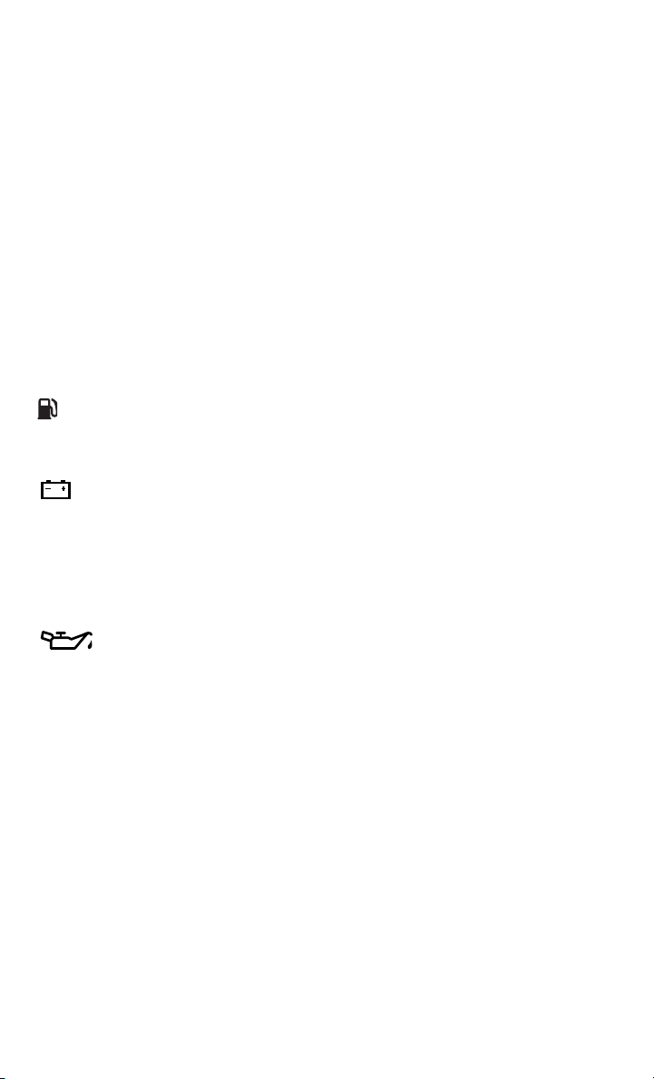
WHAT TO DO IN EMERGENCIES
ROADSIDE ASSISTANCE
Dial toll-free 1-800-521-2779 for U.S. Residents or 1-800-363-4869 for Canadian
Residents.
• Provide your name, vehicle identification number, license plate number, and your
location, including the telephone number from which you are calling.
• Briefly describe the nature of the problem and answer a few simple questions.
• You will be given the name of the service provider and an estimated time of arrival.
If you feel you are in an “unsafe situation”, please let us know. With your consent,
we will contact local police or safety authorities.
INSTRUMENT CLUSTER WARNING LIGHTS
- Low Fuel Warning Light
This warning light indicates when the fuel level reaches approximately 2.0 gal
(7.8 L), this light will turn on and a single chime will sound.
- Charging System Light
This light shows the status of the electrical charging system. If the charging system
light remains on, it means that the vehicle is experiencing a problem with the
charging system.
We recommend you do not continue driving if the charging system light is on. Have
the vehicle serviced immediately.
- Oil Pressure Warning Light
This light indicates low engine oil pressure. If the light turns on while driving, stop
the vehicle and shut off the engine as soon as possible. A chime will sound when this
light turns on.
We recommend you do not operate the vehicle or engine damage will occur. Have the
vehicle serviced immediately.
Engine Temperature Warning Light
This light warns of an overheated engine condition and is located next to the “H” hot
indicator portion of the temperature gauge.
This light warns of an overheated engine condition. As engine coolant temperatures
rise and the gauge approaches H, this indicator will illuminate and a single chime will
sound after reaching a set threshold. Further overheating will cause the temperature
gauge to pass H, a continuous chime will occur until the engine is allowed to cool or
the four minutes duration is expired, whichever comes first.
We recommend that you do not operate the vehicle or engine damage will occur. Have
the vehicle serviced immediately.
58
Page 61
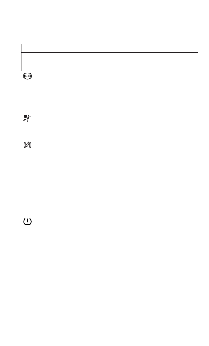
WHAT TO DO IN EMERGENCIES
WARNING!
A hot engine cooling system is dangerous. You or others could be badly burned by
steam or boiling coolant.
- Anti-Lock Brake (ABS) Light
This light monitors the Anti-Lock Brake System (ABS).
If the light is not on during starting, stays on, or turns on while driving, we
recommend you contact the nearest authorized dealer and have the vehicle serviced
immediately.
- Air Bag Warning Light
If the light is not on during starting, stays on, or turns on while driving, have the
vehicle serviced by an authorized dealer immediately.
- Electronic Throttle Control (ETC) Indicator Light
This light informs you of a problem with the system.
If a problem is detected, the light will come on while the engine is running. Cycle the
ignition when the vehicle has completely stopped and the shift lever is placed in the
PARK position; the light should turn off.
If the light remains lit with the engine running, your vehicle will usually be drivable;
however, see an authorized dealer immediately. If the light is flashing when the
engine is running, immediate service is required and you may experience reduced
performance, an elevated/rough idle or engine stall and your vehicle may require
towing.
- Tire Pressure Monitoring System (TPMS) Light
Each tire, including the spare (if provided), should be checked monthly when cold
and inflated to the inflation pressure recommended by the vehicle manufacturer on
the vehicle placard or tire inflation pressure label. (If your vehicle has tires of a
different size than the size indicated on the vehicle placard or tire inflation pressure
label, you should determine the proper tire inflation pressure for those tires.)
As an added safety feature, your vehicle has been equipped with a tire pressure
monitoring system (TPMS) that illuminates a low tire pressure telltale when one or
more of your tires is significantly under-inflated. Accordingly, when the low tire
pressure telltale illuminates, you should stop and check your tires as soon as
possible, and inflate them to the proper pressure. Driving on a significantly underinflated tire causes the tire to overheat and can lead to tire failure. Under-inflation
also reduces fuel efficiency and tire tread life, and may affect the vehicle’s handling
and stopping ability.
59
Page 62

WHAT TO DO IN EMERGENCIES
IF THE LIGHT STARTS FLASHING INDICATING A LOW TIRE PRESSURE, ADJUST THE AIR
PRESSURE IN THE LOW TIRE TO THE AIR PRESSURE SHOWN ON THE VEHICLE PLACARD OR
TIRE INFLATION PRESSURE LABEL LOCATED ON THE DRIVER'S DOOR.
NOTE:
AFTER INFLATION, THE VEHICLE MAY NEED TO BE DRIVEN FOR 20 MINUTES
BEFORE THE FLASHING LIGHT WILL TURN OFF.
Please note that the TPMS is not a substitute for proper tire maintenance, and it is
the driver’s responsibility to maintain correct tire pressure, even if under-inflation has
not reached the level to trigger illumination of the TPMS low tire pressure telltale.
Your vehicle has also been equipped with a TPMS malfunction indicator to indicate
when the system is not operating properly. The TPMS malfunction indicator is
combined with the low tire pressure telltale.
When the system detects a malfunction, the telltale will flash for approximately one
minute and then remain continuously illuminated. This sequence will continue upon
subsequent vehicle start-ups as long as the malfunction exists. When the malfunction indicator is illuminated, the system may not be able to detect or signal low tire
pressure as intended. TPMS malfunctions may occur for a variety of reasons,
including the installation of replacement or alternate tires or wheels on the vehicle
that prevent the TPMS from functioning properly. Always check the TPMS malfunction telltale after replacing one or more tires or wheels on your vehicle to ensure that
the replacement or alternate tires and wheels allow the TPMS to continue to function
properly.
NOTE:
Tire pressures change by approximately 1 psi (7 kPa) per 12° F (7° C) of air
temperature change. Keep this in mind when checking tire pressure inside a garage,
especially in the Winter. Example: If garage temperature is 68°F (20°C) and the
outside temperature is 32°F (0°C), then the cold tire inflation pressure should be
increased by 3 psi (21 kPa), which equals 1 psi (7 kPa) for every 12°F (7°C) for this
outside temperature condition.
CAUTION!
The TPMS has been optimized for the original equipment tires and wheels. TPMS
pressures and warning have been established for the tire size equipped on your
vehicle. Undesirable system operation or sensor damage may result when using
replacement equipment that is not of the same size, type, and/or style. Aftermarket wheels can cause sensor damage. Do not use tire sealant from a can, or
balance beads if your vehicle is equipped with a TPMS, as damage to the sensors
may result.
60
Page 63
WHAT TO DO IN EMERGENCIES
- Seat Belt Reminder Light
When the ignition switch is first turned to the ON/RUN position, this light will turn on
for four to eight seconds as a bulb check. During the bulb check, if the driver's seat
belt is unbuckled, a chime will sound. After the bulb check or when driving, if the
driver or front passenger seat belt remains unbuckled, the Seat Belt Indicator Light
will flash or remain on continuously. Refer to “Seat Belt Systems” in “Things To
Know Before Starting” in the OM on your DVD for further information.
- Brake Warning Light
The Brake Warning light illuminates when there is either a system malfunction or the
parking brake is applied. If the light is on and the parking brake is not applied, it
indicates a possible brake hydraulic malfunction, brake booster problem or an
Anti-Lock Brake System problem.
Please have your vehicle serviced immediately.
WARNING!
Driving a vehicle with the red brake light on is dangerous. Part of the brake system
may have failed. It will take longer to stop the vehicle. You could have a collision.
Have the vehicle checked immediately.
- Malfunction Indicator Light (MIL)
Certain conditions, such as a loose or missing gas cap, poor fuel quality, etc., may
illuminate the MIL after engine start. The vehicle should be serviced if the light stays
on through several typical driving cycles. In most situations, the vehicle will drive
normally and not require towing.
If the MIL flashes when the engine is running, serious conditions may exist that could
lead to immediate loss of power or severe catalytic converter damage. We recommend
you do not operate the vehicle. Have the vehicle serviced immediately.
- Generic Warning Light
The Generic Warning Light will illuminate if any of the following conditions occur: Oil
Change Request, Engine Oil Pressure Sensor Failure, External Light Failure, Fuel
Cut-Off Intervention, Fuel Cut-Off Not Available, Parking Sensor Failure, Engine Oil
Minimum Level, Engine Oil Minimum Level Sensor Fail.
61
Page 64

WHAT TO DO IN EMERGENCIES
INSTRUMENT CLUSTER INDICATOR LIGHTS
- Turn Signal Indicator
The arrows will flash with the exterior turn signals when the turn signal lever is
operated. A tone will chime, and a EVIC message will appear if either turn signal is
left on for more than 1 mile (1.6 km).
NOTE:
If either indicator flashes at a rapid rate, check for a defective outside light bulb.
- High Beam Indicator
Indicates that headlights are on high beam.
- Front Fog Light Indicator
This indicator will illuminate when the front fog lights are on.
- Park/Headlight ON Indicator
This indicator will illuminate when the park lights or headlights are turned on.
- Vehicle Security Light
This light will flash rapidly for approximately 15 seconds when the vehicle theft
alarm is arming. The light will flash at a slower speed continuously after the alarm is
set. The security light will also come on for about three seconds when the ignition is
first turned on.
- Electronic Speed Control SET Indicator
This indicator will illuminate when the cruising speed has been set.
- Door Ajar Indicator
This indicator will illuminate when a door(s) is left ajar and not fully closed.
- Electronic Stability Control (ESC) OFF Indicator Light
This light indicates the ESC system has been turned off by the driver.
Partial Off
This mode is entered by momentarily pressing the ESC Off switch. This mode is
intended for times when a more spirited driving experience is desired. It is also
intended for driving in deep snow, sand or gravel conditions, when more wheel spin
than ESC would normally allow is required to gain traction. To turn ESC on again,
momentarily press the switch again. This will restore the normal ESC On mode of
operation.
62
Page 65

WHAT TO DO IN EMERGENCIES
- Electronic Stability Control (ESC) Activation / Malfunction
Indicator Light
The “ESC Activation/Malfunction Indicator Light” in the instrument cluster will
come on for four seconds when the ignition switch is turned to the ON/RUN position.
If the “ESC Activation/Malfunction Indicator Light” comes on continuously with the
engine running, a malfunction has been detected in the ESC system. If this light
remains on, see your authorized dealer as soon as possible to have the problem
diagnosed and corrected.
NOTE:
• The “ESC Off Indicator Light” and the “ESC Activation/Malfunction Indicator
Light” come on momentarily each time the ignition switch is turned to ON/RUN.
• Each time the ignition is turned to ON/RUN, the ESC system will be ON even if it
was turned off previously.
• ESC Activation/Malfunction Light can blink during a ESC or TC intervention.
- Windshield Washer Fluid Low Indicator
This indicator will illuminate when the windshield washer fluid is low.
IF YOUR ENGINE OVERHEATS
In any of the following situations, you can reduce the potential for overheating by
taking the appropriate action:
• On the highways — slow down.
• In city traffic — while stopped, shift the transmission to NEUTRAL, but do not
increase engine idle speed.
NOTE:
There are steps that you can take to slow down an impending overheat condition:
• If your air conditioner (A/C) is on, turn it off. The A/C system adds heat to the
engine cooling system and turning the A/C off can help remove this heat.
• You can also turn the temperature control to maximum heat, the mode control to
floor and the blower control to high. This allows the heater core to act as a
supplement to the radiator and aids in removing heat from the engine cooling
system.
CAUTION!
Driving with a hot cooling system could damage your vehicle. If the temperature
gauge reads HOT (H), pull over and stop the vehicle. Idle the vehicle with the air
conditioner turned off until the pointer drops back into the normal range. If the
pointer remains on HOT (H), and you hear continuous chimes, turn the engine off
immediately, and call for service.
63
Page 66

WHAT TO DO IN EMERGENCIES
WARNING!
You or others can be badly burned by hot engine coolant (antifreeze) or steam from
your radiator. If you see or hear steam coming from under the hood, do not open
the hood until the radiator has had time to cool. Never try to open a cooling system
pressure cap when the radiator or coolant bottle is hot.
JACKING AND TIRE CHANGING
WARNING!
• Do not attempt to change a tire on the side of the vehicle close to moving traffic.
Pull far enough off the road to avoid the danger of being hit when operating the
jack or changing the wheel.
• Being under a jacked-up vehicle is dangerous. The vehicle could slip off the jack
and fall on you. You could be crushed. Never put any part of your body under a
vehicle that is on a jack. If you need to get under a raised vehicle, take it to a
service center where it can be raised on a lift.
• Never start or run the engine while the vehicle is on a jack.
• The jack is designed to be used as a tool for changing tires only. The jack should
not be used to lift the vehicle for service purposes. The vehicle should be jacked
on a firm level surface only. Avoid ice or slippery areas.
64
Page 67

WHAT TO DO IN EMERGENCIES
Jack And Tools Location
The jack and jack tools are stored under the front passenger seat.
To release the jack kit for it’s storage
location, you must push down and turn
the lock knob 1/4 turn counter clockwise
to the unlock position.
Jack Kit Location
CAUTION!
Do not force lock knob over limit. Damage to lock knob may occur.
To open the jack kit container you must
push the containers release to separate
the top and bottom.
Lock Knob
1 — Unlock Position
2 — Lock Position
65
Page 68

WHAT TO DO IN EMERGENCIES
Removing The Spare Tire
1. Remove the spare tire before attempting to jack up the vehicle. Attach the
lug bolt adapter to the winch extension and insert it into the winch
mechanism.
Container Release
66
Jacking Tools
1 — Jack
2 — Reversible Tool
3 — Tool Handle
4 — Winch Extension
5 — Tow Eye
6 — Wrench Handle
7 — Lug Bolt Adaptor
Page 69

WHAT TO DO IN EMERGENCIES
The winch mechanism is located under the rear of the vehicle to the right
of the spare tire.
Jack Tools
1 — Wrench Handle
2 — Lug Bolt Adapter
3 — Winch Extension
Winch Location
67
Page 70

WHAT TO DO IN EMERGENCIES
2. Rotate the wheel wrench handle
counterclockwise until the spare tire
is on the ground with enough cable
slack to allow you to pull it out from
under the vehicle.
NOTE:
The winch mechanism is designed for
use with the winch extension tube only.
Use of an air wrench or other power tools
is not recommended and can damage the
winch.
Winch Location
3. Pull the spare tire out from under the
vehicle to gain access to the spare tire
retainer.
Winch Extension
68
Lowering Spare Tire
Page 71

WHAT TO DO IN EMERGENCIES
4. Remove the retainer nut prior to removing the retainer from the wheel.
5. Lift the spare tire with one hand to
give clearance to tilt the retainer at
the end of the cable.
Spare Tire
6. Pull the retainer through the center of
the wheel.
Retainer Nut
Lifting Spare Tire
69
Page 72
WHAT TO DO IN EMERGENCIES
Preparations
1. Park the vehicle on a firm, level surface. Avoid ice or slippery areas.
Retainer
WARNING!
Do not attempt to change a tire on the side of the vehicle close to moving traffic,
pull far enough off the road to avoid the danger of being hit when operating the
jack or changing the wheel.
2. Turn on the Hazard Warning flasher.
3. Set the parking brake firmly.
4. Set an automatic transmission in PARK; a manual transmission in REVERSE.
5. Turn the ignition OFF.
6. Block the front and rear of the wheel diagonally opposite of the jacking position.
For example, if changing the right front tire, block the left rear wheel.
NOTE:
Passengers should not remain in the
vehicle when the vehicle is being jacked.
70
Wheels Blocked
Page 73
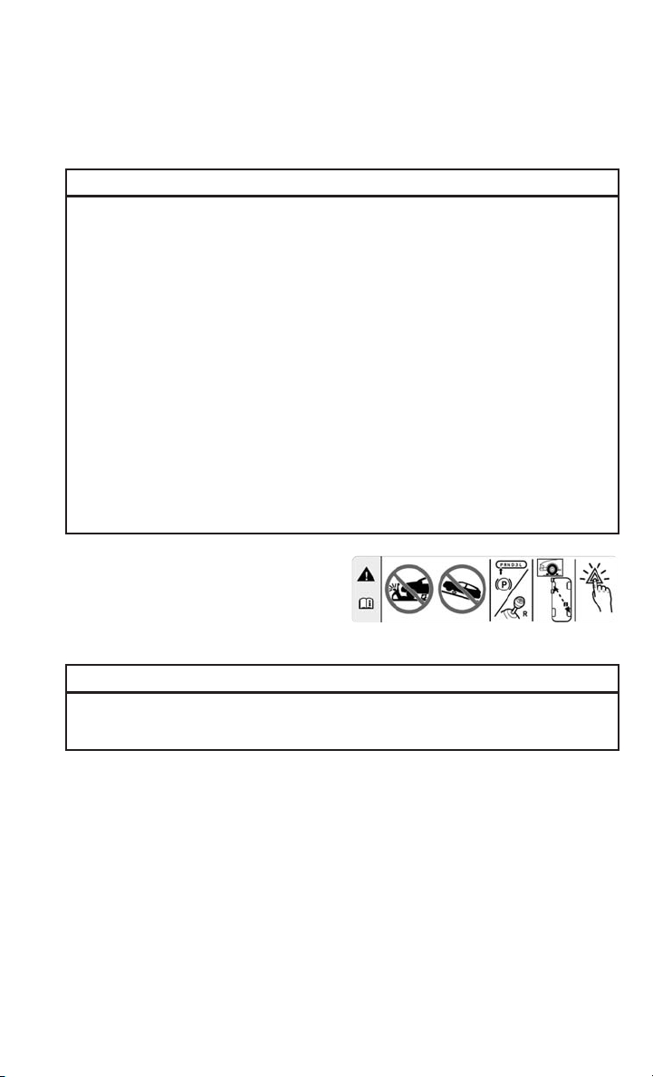
WHAT TO DO IN EMERGENCIES
Jacking Instructions
WARNING!
Carefully follow these tire changing warnings to help prevent personal injury or
damage to your vehicle:
• Always park on a firm, level surface as far from the edge of the roadway as
possible before raising the vehicle.
• Turn on the Hazard Warning flashers.
• Block the wheel diagonally opposite the wheel to be raised.
• Set the parking brake firmly and set an automatic transmission in PARK; a
manual transmission in REVERSE.
• Never start or run the engine with the vehicle on a jack.
• Do not let anyone sit in the vehicle when it is on a jack.
• Do not get under the vehicle when it is on a jack. If you need to get under a raised
vehicle, take it to a service center where it can be raised on a lift.
• Only use the jack in the positions indicated and for lifting this vehicle during a
tire change.
• If working on or near a roadway, be extremely careful of motor traffic.
• To assure that spare tires, flat or inflated, are securely stowed, spares must be
stowed with the valve stem facing the ground.
Jack Warning Label
CAUTION!
Do not attempt to raise the vehicle by jacking on locations other than those
indicated in the Jacking Instructions for this vehicle.
71
Page 74

WHAT TO DO IN EMERGENCIES
1. Loosen (but do not remove) the wheel
lug bolts by turning them to the left
one turn while the wheel is still on the
ground.
2. There are two jack engagement locations on each side of the vehicle body.
Assembled Jack
Jacking Engagement Locations
CAUTION!
Do not attempt to raise the vehicle by jacking on locations other than those
indicated.
NOTE:
The rear jacking location is located in front of the rear tire and in front of the leaf
spring mount.
72
Page 75

WHAT TO DO IN EMERGENCIES
NOTE:
The front jacking location is located behind the front tire and in front of the
driver/passenger door.
Rear Jacking Location
Front Jacking Location
WARNING!
Being under a jacked-up vehicle is dangerous. The vehicle could slip off the jack
and fall on you. You could be crushed. Never get any part of your body under a
vehicle that is on a jack. If you need to get under a raised vehicle, take it to a
service center where it can be raised on a lift.
3. Place the wrench handle and lug bolt adapter on the jack screw and turn to the
right until the jack head is properly engaged in the described location. Do not raise
the vehicle until you are sure the jack is securely engaged.
4. Raise the vehicle by turning the jack screw to the right, using the wrench handle
and lug bolt adapter. Raise the vehicle only until the tire just clears the surface
and enough clearance is obtained to install the spare tire. Minimum tire lift
provides maximum stability.
73
Page 76

WHAT TO DO IN EMERGENCIES
WARNING!
Raising the vehicle higher than necessary can make the vehicle less stable. It
could slip off the jack and hurt someone near it. Raise the vehicle only enough to
remove the tire.
Remove the wheel lug bolts. For vehicles with wheel covers, remove the cover from the
5.
wheel by hand. Do not pry the wheel cover off. Then pull the wheel off the hub.
6. Install the spare tire. Lightly tighten the wheel lug bolts.
Mounting Spare Tire
WARNING!
To avoid the risk of forcing the vehicle off the jack, do not tighten the wheel nuts
fully until the vehicle has been lowered. Failure to follow this warning may result
in personal injury.
CAUTION!
Be sure to mount the spare tire with the valve stem facing outward. The vehicle
could be damaged if the spare tire is mounted incorrectly.
NOTE:
Do not install the wheel cover on the spare tire.
7. Lower the vehicle by turning the jack screw to the left.
8. Refer to “Torque Specifications” in the Owner’s Manual on DVD for proper wheel
lug bolt torque.
9. Lower the jack to its fully-closed position.
10. Stow the damaged wheel/spare tire with the cable and wheel spacer before
driving the vehicle.
74
Page 77

WHAT TO DO IN EMERGENCIES
11. Install the winch extension and rotate the wrench handle clockwise until the winch
mechanism indication window turns yellow and the operator hears “3 clicks” from
the device to show the wheel is properly stowed under the vehicle.
Winch Mechanism Properly Engaged (Yellow
DOT Will Appear In The Winch Indication
Window)
Winch Mechanism NOT Properly Engaged
(Black Window Will Appear)
CAUTION!
In the case that the yellow dot does not appear in the winch mechanism window
refer to step 11 above, the operator should repeat the spare tire installation
procedure. If the yellow dot does not appear in the winch indication window, place
and secure the damaged wheel into the vehicle and seek dealer assistance to the
winch mechanism.
75
Page 78

WHAT TO DO IN EMERGENCIES
12. Stow the jack, jack handle and winch handle tools back in the storage
compartment.
WARNING!
A loose tire or jack thrown forward in a collision or hard stop could endanger the
occupants of the vehicle. Always stow the jack parts and the spare tire in the
places provided. Have the deflated (flat) tire repaired or replaced immediately.
13. Check the spare tire pressure as soon as possible. Correct the tire pressure, as
required.
For vehicles with aluminum wheels:
1. Remove the adapter bracket and bolts from the storage bag in the glove
compartment.
2. Take the retainer and position it inside the circular bracket.
76
Adapter/Bracket Union
Page 79
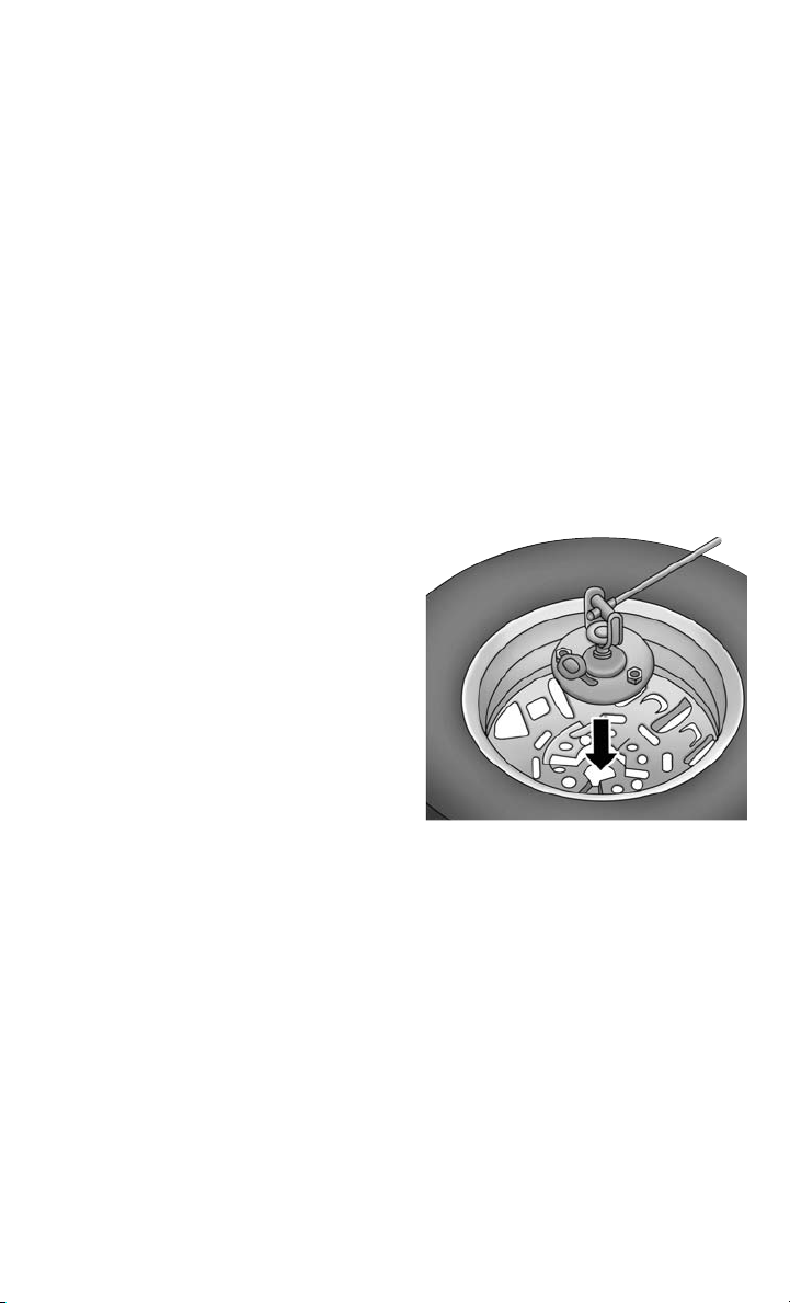
WHAT TO DO IN EMERGENCIES
3. Tighten the knob on the bolt to secure it to the bracket.
Securing The Bracket
Alloy Wheel Mounting
77
Page 80

WHAT TO DO IN EMERGENCIES
4. Position the tire vertically and lay the mounted adapter on the inner part of the
rim. Using the supplied bolts, fasten the wheel to the adapter using the bolt
install wrench. Tighten the bolts with the wrench extension and wrench handle.
5. Follow the steps above for proper spare
tire stowage.
Wheel/Bolts Attaching To Mounting Bracket
Wheel Covers
CAUTION!
Use a back-and-forth motion to remove the hub cap. Do not use a twisting motion
when removing the hub cap, damage to the hub cap finish may occur.
The wheel covers on the vehicle are held in place by the wheel lug bolts and can be
removed after the wheel lug bolts are taken off.
78
Page 81

WHAT TO DO IN EMERGENCIES
JUMP-STARTING
Preparations For Jump-Starting
NOTE:
Only use the recommended jump starting
location.
The vehicle’s jump starting locations are
located under the hood in the engine
compartment on the driver’s side.
• The Remote Positive (+) Post is cov-
ered with a protective cap located on
the side of the Front Power Distribution Center.
• The Remote Negative (-) Post is lo-
cated on the core support closest to
the front of the vehicle.
Jump-Starting Procedure
If frequent jump-starting is required to
start your vehicle you should have the
battery and charging system inspected at
your authorized dealer.
Connecting The Jumper Cables
1. Connect the positive (+) end of the jumper cable to the remote positive (+) post
of the discharged vehicle.
2. Connect the opposite end of the positive (+) jumper cable to the positive (+) post
of the booster battery.
3. Connect the negative end (-) of the jumper cable to the negative (-) post of the
booster battery.
4. Connect the opposite end of the negative (-) jumper cable to the remote negative
(-) post of the discharged vehicle.
5. Start the engine in the vehicle that has the booster battery, let the engine idle a
few minutes, and then start the engine in the vehicle with the discharged battery.
NOTE:
The remote negative (-) post is located in the front of the engine compartment on the
driver's side.
1 — Remote Positive (+) Jump Starting
2 — Remote Negative (-) Jump Starting
Remote Battery Posts
Post
Post
79
Page 82

WHAT TO DO IN EMERGENCIES
Once the engine is started, disconnect the jumper cables in the reverse sequence:
Disconnecting The Jumper Cables
1. Disconnect the negative end (-) of the jumper cable from the remote negative (-)
post of the vehicle with the discharged battery.
2. Disconnect the opposite end of the negative (-) jumper cable from the negative (-)
post of the booster battery.
3. Disconnect the positive end (+) of the jumper cable from the positive (+) post of
the booster battery.
4. Disconnect the opposite end of the positive (+) jumper cable from the remote
positive (+) post of the discharged vehicle.
5. Close the cover of the Front Power Distribution Center.
NOTE:
Only use the specific negative post. Do not use any other exposed metal parts.
CAUTION!
• Do not use a portable battery booster pack or any other booster source with a
system voltage greater than 12 Volts or damage to the battery, starter motor,
alternator or electrical system may occur.
• Failure to follow these procedures could result in damage to the charging system
of the booster vehicle or the discharged vehicle.
• Accessories that can be plugged into the vehicle power outlets draw power from
the vehicle’s battery, even when not in use (e.g., cellular phones, etc.).
Eventually, if plugged in long enough, the vehicle’s battery discharges sufficiently to degrade battery life and/or prevent the engine from starting.
80
Page 83

WHAT TO DO IN EMERGENCIES
WARNING!
• When temperatures are below the freezing point, electrolyte in a discharged
battery may freeze. Do not attempt jump-starting because the battery could
rupture or explode and cause personal injury. Battery temperature must be
brought above the freezing point before attempting a jump-start.
• Take care to avoid the radiator cooling fan whenever the hood is raised. It can
start anytime the ignition switch is on. You can be injured by moving fan blades.
• Remove any metal jewelry, such as watch bands or bracelets, that might make
an inadvertent electrical contact. You could be severely injured.
• Batteries contain sulfuric acid that can burn your skin or eyes and generate
hydrogen gas which is flammable and explosive. Keep open flames or sparks
away from the battery.
• Do not allow vehicles to touch each other as this could establish a ground
connection and personal injury could result.
• Failure to follow this procedure could result in personal injury or property
damage due to battery explosion.
• Do not connect the cable to the negative post (-) of the discharged battery. The
resulting electrical spark could cause the battery to explode and could result in
personal injury.
SHIFT LEVER OVERRIDE
If a malfunction occurs and the shift lever cannot be moved out of the PARK position,
you can use the following procedure to temporarily move the shift lever:
1. Turn the engine off.
2. Firmly apply the parking brake.
3. Using a small screwdriver or similar tool, remove the shift lever override access
cover which is located below the shift lever.
4. Press and maintain firm pressure on the brake pedal.
5. Insert the screwdriver or similar tool into the access port, and push and hold the
override release lever.
6. Move the shift lever to the NEUTRAL position.
7. The vehicle may then be started in NEUTRAL.
8. Reinstall the shift lever override access cover.
81
Page 84

WHAT TO DO IN EMERGENCIES
TOWING A DISABLED VEHICLE
Towing
Condition
Flat Tow NONE
Wheel
Lift or
Dolly
Tow
Flatbed
FREEING A STUCK VEHICLE
• If your vehicle becomes stuck in mud, sand or snow, it can often be moved by a
rocking motion. Turn your steering wheel right and left to clear the area around the
front wheels. Then, move the shift lever/gear selector back and forth between
REVERSE and DRIVE. Using minimal accelerator pedal pressure to maintain the
rocking motion, without spinning the wheels, is most effective.
• Allow the engine to idle with the transmission shift lever/gear selector in NEUTRAL for at least one minute after every five rocking-motion cycles. This minimizes overheating and reduce the risk of transmission failure during prolonged
efforts to free a stuck vehicle.
Wheels
OFF the
Ground
Rear Transmission in NEUTRAL
Front OK OK
ALL BEST METHOD
Gasoline Engines (All Models) Diesel Engines (All Models)
If transmission is operable:
•
Transmission in NEUTRAL
• 25 mph (40 km/h) max
speed
• 15 miles (24 km) max
distance
Transmission in NEUTRAL
OK
NOTE:
If your vehicle is equipped with Electronic Stability Control (ESC) then press the
"ESC Off" switch, to place the Electronic Stability Control (ESC) system in "Partial
Off" mode, before rocking the vehicle.
CAUTION!
Revving the engine or spinning the wheels too fast may lead to transmission
overheating and failure. It can also damage the tires. Do not spin the wheels above
30 mph (48 km/h) while in gear (no transmission shifting occurring).
WARNING!
Fast spinning tires can be dangerous. Forces generated by excessive wheel speeds
may cause tire damage or failure. A tire could explode and injure someone. Do not
spin your vehicle's wheels faster than 30 mph (48 km/h) when you are stuck. Do
not let anyone near a spinning wheel, no matter what the speed.
82
Page 85

WHAT TO DO IN EMERGENCIES
EVENT DATA RECORDER (EDR)
This vehicle is equipped with an Event Data Recorder (EDR). The main purpose of an
EDR is to record, in certain crash or near crash-like situations, such as an air bag
deployment or hitting a road obstacle, data that will assist in understanding how a
vehicle’s systems performed. The EDR is designed to record data related to vehicle
dynamics and safety systems for a short period of time, typically 30 seconds or less.
The EDR in this vehicle is designed to record such data as:
• How various systems in your vehicle were operating.
• Whether or not the driver and passenger safety belts were buckled/fastened.
• How far (if at all) the driver was depressing the accelerator and/or brake pedal.
• How fast the vehicle was traveling.
These data can help provide a better understanding of the circumstances in which
crashes and injuries occur.
NOTE:
EDR data is recorded by your vehicle only if a non-trivial crash situation occurs; no
data is recorded by the EDR under normal driving conditions and no personal data
(e.g. name, gender, age, and crash location) is recorded. However, other parties, such
as law enforcement, could combine the EDR data with the type of personally
identifying data routinely acquired during a crash investigation.
To read data recorded by an EDR, special equipment is required, and access to the
vehicle or the EDR is needed. In addition to the vehicle manufacturer, other parties
such as law enforcement, that have the special equipment, can read the information
if they have access to the vehicle or the EDR.
83
Page 86

MAINTAINING YOUR VEHICLE
OPENING THE HOOD
1. Open the drivers door to gain access
to the hood release lever. Pull the
hood release lever located on the side
of the instrument panel.
2. Move to the outside of the vehicle,
reach into the opening beneath the
center of the hood and push the safety
latch lever to the right to release it,
before raising the hood.
3. Raise the hood and place the hood
prop rod in hood slot to secure the
hood in the open position.
4. To close the hood, remove the hood
prop rod and place it in the retaining
clip, then lower the hood slowly.
Be sure the hood is fully latched before driving your vehicle. If the hood is not fully
latched, it could open when the vehicle is in motion and block your vision. Failure
to follow this warning could result in serious injury or death.
1 — Hood Release Lever
WARNING!
84
Page 87

MAINTAINING YOUR VEHICLE
ENGINE COMPARTMENT
3.6L Engine
85
Page 88
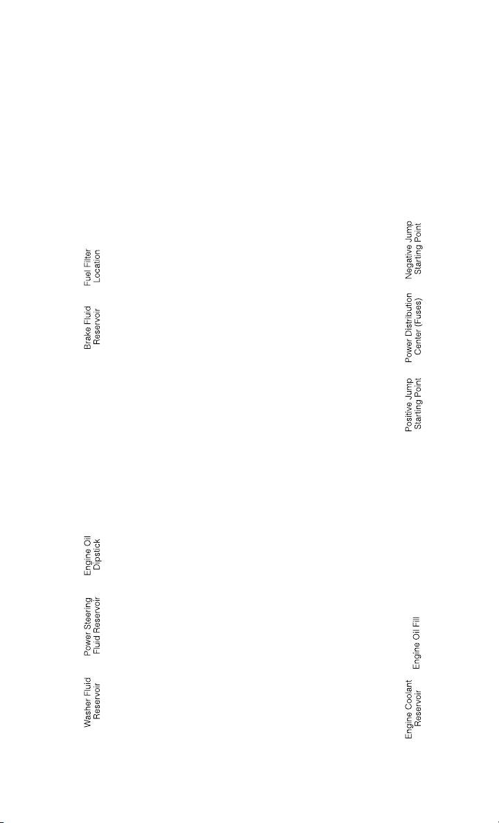
MAINTAINING YOUR VEHICLE
3.0L Diesel Engine
86
Page 89
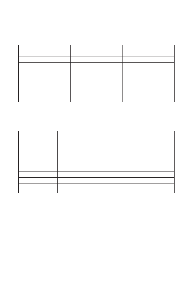
MAINTAINING YOUR VEHICLE
FLUID CAPACITIES — GASOLINE ENGINE
U.S. Metric
Fuel (Approximate)
Engine Oil with Filter
3.6L Engine (SAE 5W-20,
API Certified)
Cooling System *
3.6L Engine (MOPAR
Antifreeze/Engine Coolant
10 Year/150,000 Mile
Formula or equivalent)
®
FLUIDS, LUBRICANTS AND GENUINE PARTS — GASOLINE ENGINE
Engine
Component Fluid, Lubricant, or Genuine Part
We recommend you use MOPAR
Engine Coolant
Engine Oil
Engine Oil Filter We recommend you use MOPAR
Spark Plugs We recommend you use MOPAR
Fuel Selection 87 Octane
150,000 Mile Formula OAT (Organic Additive Technology) meeting the requirements of Chrysler Material Standard MS-12106.
We recommend you use API Certified SAE 5W-20 Engine Oil,
meeting the requirements of Chrysler Material Standard
MS-6395 such as MOPAR
Refer to your engine oil filler cap for correct SAE grade.
24 Gallons 90 Liters
6 Quarts 5.6 Liters
10.5 Quarts 10 Liters
®
Antifreeze/Coolant 10 Year/
®
, Pennzoil®, and Shell Helix®.
®
Engine Oil Filters.
®
Spark Plugs.
87
Page 90
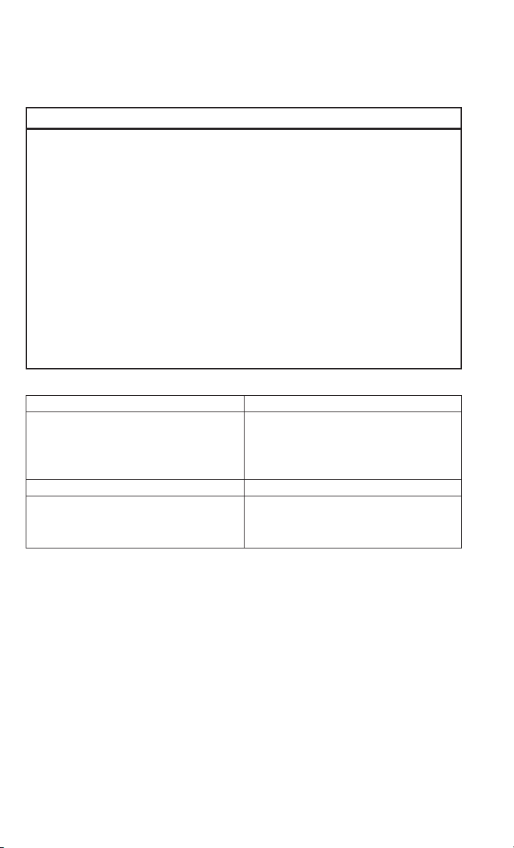
MAINTAINING YOUR VEHICLE
CAUTION!
• Mixing of engine coolant (antifreeze) other than specified Organic Additive
Technology (OAT) engine coolant (antifreeze), may result in engine damage and
may decrease corrosion protection. Organic Additive Technology (OAT) engine
coolant is different and should not be mixed with Hybrid Organic Additive
Technology (HOAT) engine coolant (antifreeze) or any “globally compatible”
coolant (antifreeze). If a non-OAT engine coolant (antifreeze) is introduced into
the cooling system in an emergency, the cooling system will need to be drained,
flushed, and refilled with fresh OAT coolant (conforming to MS-12106), by an
authorized dealer as soon as possible.
• Do not use water alone or alcohol-based engine coolant (antifreeze) products. Do
not use additional rust inhibitors or antirust products, as they may not be
compatible with the radiator engine coolant and may plug the radiator.
• This vehicle has not been designed for use with propylene glycol-based engine
coolant (antifreeze). Use of propylene glycol-based engine coolant (antifreeze)
is not recommended.
Chassis
Component Fluid, Lubricant, or Genuine Part
Automatic Transmission – 3.6L Gasoline
Engine Only
Brake Master Cylinder We recommend you use MOPAR
Power Steering Reservoir Use Pentosin CHF 11S power steering
Use Only ATF+4
Fluid. Failure to use ATF+4
affect the function or performance of your
transmission. We recommend MOPAR
ATF+4®Fluid.
fluid meeting Chrysler Material Standard
MS-11655.
®
Automatic Transmission
®
fluid may
®
DOT 4.
®
88
Page 91
MAINTAINING YOUR VEHICLE
FLUID CAPACITIES — DIESEL ENGINE
U.S. Metric
Fuel (Approximate)
3.0L Diesel Engine 24 Gallons 90 Liters
Diesel Exhaust Fluid Tank 5 Gallons 18.9 Liters
Engine Oil with Filter
3.0L Diesel Engine 9.5 Quarts 9.0 Liters
Cooling System *
3.0L Diesel Engine With
MTA Transmission
®
(MOPAR
Engine Coolant 10 Year/
150,000 Mile Formula or
equivalent)
* Includes heater and coolant recovery bottle filled to MAX level. Add 2.9 Qts (2.8 L)
if equipped with a rear heater.
FLUIDS, LUBRICANTS AND GENUINE PARTS — DIESEL ENGINE
Engine
Component Fluid, Lubricant, or Genuine Part
Engine Coolant We recommend you use MOPAR
Engine Oil Only use ACEA C3 5W-30 Synthetic Low
Engine Oil Filter We recommend you use MOPAR
Fuel Filter We recommend you use MOPAR
Antifreeze/
12.7 Quarts 12 Liters
Antifreeze/Coolant 10 Year/150,000 Mile
Formula OAT (Organic Additive Technology).
Ash engine oil meeting Chrysler material
standard MS-11106 or Pennzoil Ultra Euro
L full synthetic 5W-30 motor oil.
Oil Filters.
ter. Must meet 3 micron rating. Using a fuel
filter that does not meet the manufacturers
filtration and water separating requirements
can severely impact fuel system life and reliability.
®
Engine
®
Fuel Fil-
®
89
Page 92

MAINTAINING YOUR VEHICLE
Component Fluid, Lubricant, or Genuine Part
Fuel Selection Use good quality diesel fuel from a repu-
Diesel Exhaust Fluid MOPAR
table supplier in your vehicle. Federal law
requires that you must fuel this vehicle
with Ultra Low Sulfur Highway Diesel fuel
(15 ppm Sulfur maximum) and prohibits
the use of Low Sulfur Highway Diesel fuel
(500 ppm Sulfur maximum) to avoid damage to the emissions control system. For
most year-round service, No. 2 diesel fuel
meeting ASTM specification D-975 Grade
S15 will provide good performance. We
recommend you use a blend of up to 5%
biodiesel, meeting ASTM specification
D-975 with your diesel engine.This vehicle
is compatible with biodiesel blends greater
than 5% but no greater than 20% biodiesel
meeting ASTM specification D-7467 provided the shortened maintenance intervals
are followed as directed.
®
fied) (DEF) or equivalent that has been API
Certified to the ISO 22241 standard. Use
of fluids not API Certified to ISO
22241 may result in system damage.
Diesel Exhaust Fluid (API Certi-
NOTE:
If the vehicle is exposed to extreme cold (below 20°F or -7°C), or is required to
operate at colder-than-normal conditions for prolonged periods, use climatized No.
2 diesel fuel or dilute the No. 2 diesel fuel with 50% No. 1 diesel fuel. This will
provide better protection from fuel gelling or wax-plugging of the fuel filter.
90
Page 93
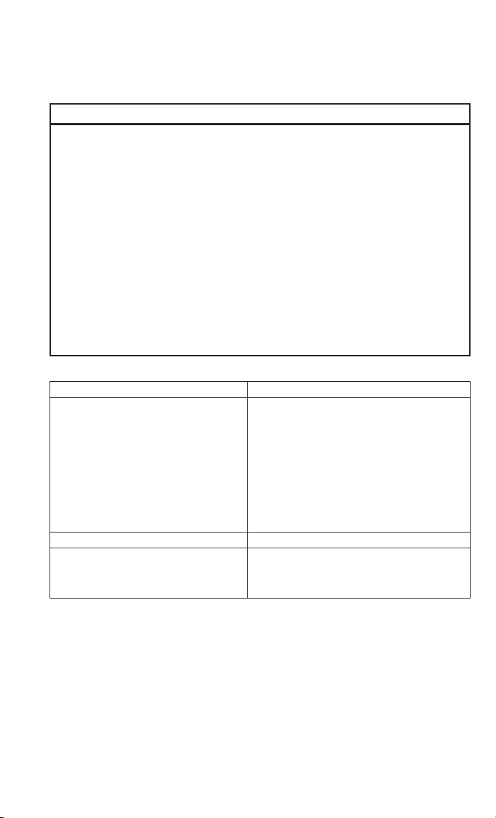
MAINTAINING YOUR VEHICLE
CAUTION!
• Mixing of engine coolant (antifreeze) other than specified Organic Additive
Technology (OAT) engine coolant (antifreeze), may result in engine damage and
may decrease corrosion protection. Organic Additive Technology (OAT) engine
coolant is different and should not be mixed with Hybrid Organic Additive
Technology (HOAT) engine coolant (antifreeze) or any “globally compatible”
coolant (antifreeze). If a non-OAT engine coolant (antifreeze) is introduced into
the cooling system in an emergency, the cooling system will need to be drained,
flushed, and refilled with fresh OAT coolant (conforming to MS-12106), by an
authorized dealer as soon as possible.
• Do not use water alone or alcohol-based engine coolant (antifreeze) products. Do
not use additional rust inhibitors or antirust products, as they may not be
compatible with the radiator engine coolant and may plug the radiator.
• This vehicle has not been designed for use with propylene glycol-based engine
coolant (antifreeze). Use of propylene glycol-based engine coolant (antifreeze)
is not recommended.
Chassis
Component Fluid, Lubricant, or Genuine Part
Automated Manual Transmission
Brake Master Cylinder We recommend you use MOPAR
Power Steering Reservoir Use Pentosin CHF 11S power steering fluid
• Gearbox: Full synthetic 75W-85 manual
transmission fluid meeting the API GL4
specification.
• Control system: MOPAR
SAE 75W Hydraulic Fluid or equivalent.
• Hydraulic Clutch Operating System:
Failure to use the correct fluid may affect the
function or performance of your transmission.
meeting Chrysler Material Standard
MS-11655.
®
MOPAR
Motor Vehicle or equivalent.
Brake and Clutch Fluid DOT 4
®
C Series DDCT
®
DOT 4.
91
Page 94

MAINTAINING YOUR VEHICLE
MAINTENANCE SCHEDULE — GASOLINE ENGINE
Your vehicle is equipped with an automatic oil change indicator system. The oil
change indicator system will remind you that it is time to take your vehicle in for
scheduled maintenance.
Based on engine operation conditions, the oil change indicator message will
illuminate in the instrument cluster. This means that service is required for your
vehicle. Operating conditions such as frequent short-trips, trailer tow, and extremely
hot or cold ambient temperatures will influence when the “Oil Change Required”
message is displayed. Severe Operating Conditions can cause the change oil
message to illuminate as early as 3,500 miles (5,600 km) since last reset. Have your
vehicle serviced as soon as possible, within the next 500 miles (805 km).
Your authorized dealer will reset the oil change indicator message after completing
the scheduled oil change. If a scheduled oil change is performed by someone other
than your authorized dealer, the message can be reset by referring to the steps
described under “Electronic Vehicle Information Center (EVIC)” in “Understanding
Your Instrument Panel” in your owners manual on the DVD for further information.
NOTE:
Under no circumstances should oil change intervals exceed 10,000 miles
(16,000 km) or twelve months, whichever comes first.
Severe Duty All Models
Change Engine Oil at 4,000 miles (6,500 km) if the vehicle is operated in a dusty
and off road environment. This type of vehicle use is considered Severe Duty.
Once A Month Or Before A Long Trip:
• Check engine oil level
• Check windshield washer fluid level
• Check the tire inflation pressures and look for unusual wear or damage
• Check the fluid levels of the coolant reservoir, brake master cylinder, and power
steering and fill as needed
• Check function of all interior and exterior lights
92
Page 95

MAINTAINING YOUR VEHICLE
Maintenance Chart
Required Maintenance Intervals
Refer to the maintenance schedules on the following page for the required maintenance intervals.
At Every Oil Change Interval As Indicated By Oil Change Indicator System:
•
Change oil and filter.
• Rotate the tires. Rotate at the first sign of irregular wear, even if it occurs before the oil
indicator system turns on.
•
Inspect battery and clean and tighten terminals as required.
•
Inspect brake pads, shoes, rotors, drums, hoses and park brake.
•
Inspect engine cooling system protection and hoses.
•
Inspect exhaust system.
•
Inspect engine air cleaner if using in dusty or off-road conditions.
93
Page 96

MAINTAINING YOUR VEHICLE
150,000
140,000
130,000
120,000
110,000
100,000
90,000
80,000
70,000
60,000
50,000
40,000
240,000
224,000
208,000
192,000
176,000
160,000
144,000
128,000
112,000
96,000
80,000
64,000
XX
X
XX
Mileage or time passed (whichever comes
Refer to the Maintenance Schedules on the following pages for the required maintenance intervals.
94
first)
30,000
20,000
Or Years: 2 3 4 5 6 7 8 9 10 11 12 13 14 15
48,000
32,000
Or Kilometers:
Additional Inspections
XXX X X X X
Inspect the CV joints. X X X X X
Inspect front suspension, tie rod ends,
boot seals, and replace if necessary.
XXX X X X X
Inspect the brake pads, replace as nec-
essary.
Additional Maintenance
Replace engine air filter. X X X X X
Replace cabin/air conditioning filter. X X X X X X X
Replace Brake Fluid every two years X X X X X X X
Replace spark plugs (3.6L engine). ** X
Flush and replace the engine coolant at
10 years or 150,000 miles
(240,000 km) whichever comes first.
Change automatic transmission fluid and
filter.
Inspect and replace PCV valve if neces-
sary.
** The spark plug change interval is mileage based only, yearly intervals do not apply.
Page 97

MAINTAINING YOUR VEHICLE
WARNING!
right equipment. If you have any doubt about your ability to perform a service job, take your vehicle to a competent mechanic.
• You can be badly injured working on or around a motor vehicle. Do only service work for which you have the knowledge and the
performance. This could cause an accident.
• Failure to properly inspect and maintain your vehicle could result in a component malfunction and effect vehicle handling and
95
Page 98

MAINTAINING YOUR VEHICLE
rized Service Center
Odometer Date Signature, Autho-
90,000 Miles
(144,000 km) or
9 Years
100,000 Miles
(160,000 km) or
10 Years
110,000 Miles
(176,000 km) or
11 Years
120,000 Miles
(192,000 km) or
12 Years
130,000 Miles
(208,000 km) or
13 Years
140,000 Miles
(224,000 km) or
14 Years
150,000 Miles
(240,000 km) or
15 Years
MAINTENANCE RECORD
96
rized Service Center
Odometer Date Signature, Autho-
20,000 Miles
(32,000 km) or
2 Years
30,000 Miles
(48,000 km) or
3 Years
40,000 Miles
(64,000 km) or
4 Years
50,000 Miles
(80,000 km) or
5 Years
60,000 Miles
(96,000 km) or
6 Years
70,000 Miles
(112,000 km) or
7 Years
80,000 Miles
(128,000 km) or
8 Years
Page 99

MAINTAINING YOUR VEHICLE
MAINTENANCE SCHEDULE — DIESEL ENGINE
Your vehicle is equipped with an automatic oil change indicator system. The oil
change indicator system will remind you that it is time to take your vehicle in for
scheduled maintenance.
Based on engine operation conditions, the oil change indicator message will
illuminate in the instrument cluster. This means that service is required for your
vehicle. Operating conditions such as frequent short-trips, trailer tow, and extremely
hot or cold ambient temperatures will influence when the “Oil Change Required”
message is displayed. Severe Operating Conditions can cause the change oil
message to illuminate as early as 3,500 miles (5,600 km) since last reset. Have your
vehicle serviced as soon as possible, within the next 500 miles (805 km).
Your authorized dealer will reset the oil change indicator message after completing
the scheduled oil change. If a scheduled oil change is performed by someone other
than your authorized dealer, the message can be reset by referring to the steps
described under “Electronic Vehicle Information Center (EVIC)” in “Understanding
Your Instrument Panel” in your Owners Manual on the DVD for further information.
NOTE:
Under no circumstances should oil change intervals exceed 18,500 miles
(29,773 km) or twelve months, whichever comes first.
Once A Month Or Before A Long Trip:
• Check engine oil level
• Check windshield washer fluid level
• Check the tire inflation pressures and look for unusual wear or damage
• Check the fluid levels of the coolant reservoir, brake master cylinder, and power
steering and fill as needed
• Check function of all interior and exterior lights
Maintenance Chart — Diesel Fuel Up To B5 Biodiesel
Required Maintenance Intervals.
Refer to the maintenance schedules on the following page for the required maintenance intervals.
At Every Oil Change Interval As Indicated By The Oil Change Indicator System:
•
Change oil and filter.
• Rotate the tires. Rotate at the first sign of irregular wear, even if it occurs before your
next scheduled service.
•
Inspect battery and clean and tighten terminals as required.
•
Inspect brake pads, rotors, hoses and park brake.
•
Inspect engine cooling system protection and hoses.
•
Inspect exhaust system.
•
Inspect engine air cleaner if using in dusty or off-road conditions.
97
Page 100

MAINTAINING YOUR VEHICLE
150,000
140,000
130,000
120,000
110,000
100,000
90,000
80,000
70,000
60,000
50,000
40,000
240,000
224,000
208,000
192,000
176,000
160,000
144,000
128,000
112,000
96,000
80,000
64,000
XX
98
Mileage or time passed
(whichever comes first)
30,000
20,000
10,000
Or Years: 1 2 3 4 5 6 7 8 9 10 11 12 13 14 15
48,000
32,000
16,000
Or Kilometers:
Additional Inspections
XXXXXXXXXXXXXXX
Completely fill the Diesel Exhaust Fluid
tank.
XXX X X X X
Inspect the CV joints. X X X X X
Inspect front suspension, tie rod ends,
boot seals, and replace if necessary.
XX X X X
XXX X X X X
Inspect the brake pads, replace as nec-
essary.
Check Transmission Actuation System
Oil and Hydraulic Clutch Operating Oil
XX X X X
Additional Maintenance
Replace fuel filter and drain water from
fuel.
Replace engine air filter. X X X X X
Replace cabin/air conditioning filter. X X X X X X X
Replace Brake Fluid every two years. X X X X X X X
Replace Hydraulic Clutch Oil every two
XXX X X X X
years or 60,000 miles (96,000 km)
which ever comes first.
Flush and replace the engine coolant
at 10 years or 150,000 miles
(240,000 km) whichever comes first.
 Loading...