

VEHICLES SOLD IN CANADA
With respect to any Vehicles Sold in Canada, the name
Chrysler LLC shall be deemed to be deleted and the
name Chrysler Canada Inc. used in substitution therefor.
DRIVING AND ALCOHOL
Drunken driving is one of the most frequent causes of
accidents.
Your driving ability can be seriously impaired with blood
alcohol levels far below the legal minimum. If you are
drinking, don’t drive. Ride with a designated non-drinking
driver, call a cab, a friend, or use public transportation.
WARNING!
Driving after drinking can lead to an accident. Your
perceptions are less sharp, your reflexes are slower,
and your judgment is impaired when you have been
drinking. Never drink and then drive.
This manual illustrates and describes the operation of
features and equipment that are either standard or optional on this vehicle. This manual may also include a
description of features and equipment that are no longer
available or were not ordered on this vehicle. Please
disregard any features and equipment described in this
manual that are not on this vehicle.
Chrysler LLC reserves the right to make changes in
design and specifications, and/or make additions to or
improvements to its products without imposing any
obligation upon itself to install them on products previously manufactured.
Copyright © 2008 Chrysler LLC

SECTION PAGE
1
INTRODUCTION
2
THINGS TO KNOW BEFORE STARTING YOUR VEHICLE
3
UNDERSTANDING THE FEATURES OF YOUR VEHICLE
4
UNDERSTANDING YOUR INSTRUMENT PANEL
5
STARTING AND OPERATING
6
WHAT TO DO IN EMERGENCIES
7
MAINTAINING YOUR VEHICLE
8
MAINTENANCE SCHEDULES
9
INDEX
....................................................................147
TABLE OF CONTENTS
.............................................................3
...............................5
................................9
.................................... 21
.................................................. 37
................................................77
................................................ 83
..................................................121


INTRODUCTION
CONTENTS
䡵 A Message From Chrysler LLC ............. 4
1

4 INTRODUCTION
A MESSAGE FROM CHRYSLER LLC
Chrysler LLC and Cummins威 welcome you as a Cummins威 turbocharged diesel-powered truck owner.
Almost 100% of all heavy duty trucks are diesel-powered
because of the fuel economy, rugged durability, and high
torque which permits pulling heavy loads. Cummins威,
engines power well over half of these trucks. Now this
same technology and proven performance is yours in
your truck equipped with the Cummins威 turbocharged
diesel engine.
Your diesel truck will sound, feel, drive, and operate
differently from a gasoline-powered truck. It is important
that you read and understand this manual. You may find
that some of the starting, operating, and maintenance
procedures are different. However, they are simple to
follow and careful adherence to them will ensure that
you take full advantage of the features of this engine.

THINGS TO KNOW BEFORE STARTING YOUR VEHICLE
CONTENTS
䡵 Steering Wheel Lock — If Equipped ......... 6
▫ To Manually Lock The Steering Wheel ......6
2
▫ To Release The Steering Wheel Lock ........ 6
䡵 Engine Break-In Recommendations .......... 6

6 THINGS TO KNOW BEFORE STARTING YOUR VEHICLE
STEERING WHEEL LOCK — IF EQUIPPED
Your vehicle may be equipped with a passive steering
wheel lock. This lock prevents steering the vehicle without the ignition key. If the steering wheel is moved
approximately a half turn in either direction and the key
is not in the ignition switch, the steering wheel will lock.
To Manually Lock the Steering Wheel
With the engine running, turn the steering wheel upside
down, turn off the engine and remove the key. Turn the
steering wheel slightly in either direction until the lock
engages.
To Release the Steering Wheel Lock
Insert the key in the ignition switch and start the engine.
If the key is difficult to turn, move the wheel slightly to
the right or left to disengage the lock.
NOTE: If you turned the wheel to the right to engage
the lock, you must turn the wheel slightly to the right to
disengage it. If you turned the wheel to the left to engage
the lock, turn the wheel slightly to the left to disengage it.
ENGINE BREAK-IN RECOMMENDATIONS
The Cummins威 turbocharged diesel engine does not
require a break-in period due to its construction. Normal
operation is allowed, providing the following recommendations are followed:
NOTE: Light duty operation such as light trailer towing
or no load operation will extend the time before the
engine is at full efficiency. Reduced fuel economy and
power may be seen at this time.

THINGS TO KNOW BEFORE STARTING YOUR VEHICLE 7
For additional vehicle break-in requirements, refer to
“Trailer Towing” in Section 5 of the Owners Manual.
•
Warm up the engine before placing it under load.
•
Do not operate the engine at idle for prolonged
periods.
•
Use the appropriate transmission gear to prevent
engine lugging.
•
Observe vehicle oil pressure and temperature indicators.
•
Check the coolant and oil levels frequently.
•
Vary throttle position at highway speeds when carrying or towing significant weight.
Because of the construction of the Cummins威 turbocharged diesel engine, engine run-in is enhanced by
loaded operating conditions which allow the engine
parts to achieve final finish and fit during the first
6,000 miles (10 000 km).
2


UNDERSTANDING THE FEATURES OF YOUR VEHICLE
CONTENTS
䡵 Overhead Console With Electronic Vehicle
Information Center (EVIC)................. 10
▫ Electronic Vehicle Information Center (EVIC)
— If Equipped ....................... 11
3
▫ Dome/Reading Lights ................ 10
▫ Compass/Temperature Button ........... 18

10 UNDERSTANDING THE FEATURES OF YOUR VEHICLE
OVERHEAD CONSOLE WITH ELECTRONIC VEHICLE INFORMATION CENTER (EVIC)
The overhead console contains dome/reading lights, and
an Electronic Vehicle Information Center (EVIC).
Dome/Reading Lights
Located in the overhead console are two dome/reading
lights.
The dome/reading lights illuminate when a door is
opened or when the interior lights are turned on by
rotating the dimmer control located on the headlight
switch.
The reading lights are activated by pressing on the
recessed area of the corresponding lens.
NOTE: The dome/reading lights will remain on until
the switch is pressed a second time, so be sure they have
been turned off before leaving the vehicle.
Dome/Reading Lights
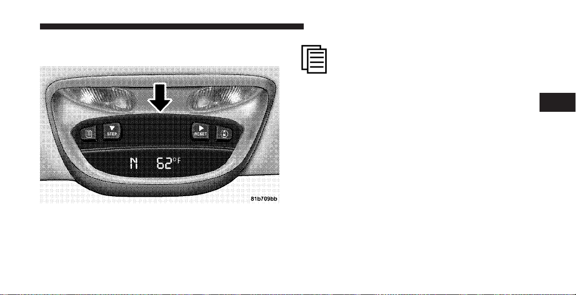
UNDERSTANDING THE FEATURES OF YOUR VEHICLE 11
Electronic Vehicle Information Center (EVIC) — If
Equipped
Overhead Console With EVIC
Pressing the MENU button will change the
display to one of the following features:
Trip Functions
Pressing the STEP button allows you to scroll through
one of the following Trip Function features:
•
TRIP – Shows the total distance traveled since the last
reset. To reset the TRIP function, press and hold the
RESET button.
•
ELAPSED TIME – Shows the total elapsed time of
travel since the last reset. Elapsed time will increment
when the ignition switch is in the ON/RUN or START
positions.
•
UNIT IN US/METRIC – Press the RESET button to
toggle between US and METRIC.
3

12 UNDERSTANDING THE FEATURES OF YOUR VEHICLE
•
AVG. MPG – Shows the average fuel economy since
the last reset. When the fuel economy is reset, the
display will show dashes for two seconds. Then the
history information will be erased, and the averaging
will continue from the last fuel average reading before
the reset. (Example: If your EVIC displays 18 AVG.
MPG and the RESET button is pressed, the previous
averaging history will be erased and the display will
return to the 18 AVG. MPG, not to 0 AVG. MPG.) The
display may take several miles/kilometers for the
value to change, dependent upon driving habits.
•
MI TO EMPTY (Distance to Empty) – Shows the
estimated distance that can be traveled with the fuel
remaining in the tank. This estimated distance is
determined by a weighted average of fuel economy,
according to the current fuel tank level. MI TO EMPTY
cannot be reset through the RESET button.
NOTE: Significant changes in driving style or vehicle
loading will greatly affect the actual drivable distance of
the vehicle, regardless of the MI TO EMPTY displayed
value.
When the MI TO EMPTY value is less than 30 miles
(48 km) estimated driving distance, the MI TO EMPTY
display will change to a text display of ⬙LOW FUEL.⬙
This display will continue until the vehicle runs out of
fuel. Adding a significant amount of fuel to the vehicle
will turn off the ⬙LOW FUEL⬙ text and a new MI TO
EMPTY value will display.
System Status (EVIC Displays)
When the appropriate conditions exist, the EVIC displays
the following messages:
•
TURN SIGNALS ON (with a continuous warning
chime)

•
PERSONAL SETTINGS NOT AVAILABLE – Vehicle
not in PARK or Vehicle in Motion (Manual Transmission Only)
•
LEFT/RIGHT FRONT DOOR AJAR (one or more,
with a single chime if speed is above 1 mph (1.6 km/h)
•
LEFT/RIGHT REAR DOOR AJAR (one or more, with
a single chime if speed is above 1 mph (1.6 km/h)
•
DOOR(S) AJAR (with a single chime if vehicle is in
motion)
•
LOW WASHER FLUID (with a single chime)
•
OIL CHANGE REQUIRED (with a single chime)
•
SERVICE AIR FILTER
•
PERFORM SERVICE
•
EXHAUST FILTER XX% FULL
UNDERSTANDING THE FEATURES OF YOUR VEHICLE 13
•
EXHAUST FILTER FULL — POWER REDUCED SEE
DEALER
•
SERVICE REQUIRED — SEE DEALER NOW
•
EXHAUST SYSTEM — REGENERATION REQUIRED
NOW
•
EXHAUST SYSTEM — REGENERATION IN PROCESS
•
EXHAUST SYSTEM — REGENERATION COMPLETED
•
TIRE PRESSURE LT LOAD SET
•
TIRE PRESSURE MAX LOAD SET
Oil Change Required — If Equipped
Your vehicle is equipped with an engine oil change
indicator system. The “Oil Change Required” message
will flash in the EVIC display for approximately 10 seconds after a single chime has sounded to indicate the next
3

14 UNDERSTANDING THE FEATURES OF YOUR VEHICLE
scheduled oil change interval. The engine oil change
indicator system is duty cycle based, which means the
engine oil change interval may fluctuate, dependent
upon your personal driving style.
NOTE: When prompted by the Engine Oil Change
Indicator System, the engine oil and filter must be
changed. If not prompted by the Engine Oil Change
Indicator System within 7,500 miles (12 000 km) or
six months since the last oil and filter change, change the
engine oil and engine oil filter. Under no circumstances
should engine oil intervals exceed 7,500 miles
(12 000 km) or six months, whichever comes first.
Unless reset, this message will continue to display each
time you turn the ignition switch to the ON/RUN
position. To turn off the message temporarily, press and
release the MENU button. To reset the oil change indicator system (after performing the scheduled maintenance)
use the following procedure.
1. Turn the ignition switch to the ON position (do not
start the engine).
2. Fully depress the accelerator pedal slowly three times
within 10 seconds.
3. Turn the ignition switch to the OFF/LOCK position.
NOTE: If the indicator message illuminates when you
start the vehicle, the oil change indicator system did not
reset. If necessary, repeat this procedure.
Perform Service
This vehicle will require emissions maintenance at a set
interval. To help remind you when this maintenance is
due, the Electronic Vehicle Information Center (EVIC)
will display “Perform Service.” When the “Perform Service” message is displayed on the EVIC, it is necessary to
have the emissions maintenance performed. Emissions
maintenance includes replacing the Closed Crankcase
Ventilation (CCV) filter element, cleaning of the EGR

UNDERSTANDING THE FEATURES OF YOUR VEHICLE 15
Cooler, and cleaning of the EGR Valve. The procedure for
clearing and resetting the “Perform Service” indicator
message is located in the appropriate service information.
Refer to the “Maintenance Schedule” in Section 8 for the
proper emission maintenance intervals.
Personal Settings (Customer Programmable
Features)
Personal settings allows the driver to set and recall
features when the transmission is in PARK. If the transmission is not in PARK, the EVIC will display NOT
AVAILABLE and VEHICLE NOT IN PARK.
Press and release the MENU button until the
Personal Settings displays on the EVIC.
Use the STEP button to display one of the following:
•
“LANGUAGE” – When in this display you may select
one of three languages for all display nomenclature,
including the trip functions. Press the RESET button
while in this display to select English, Espanol, or
Francais. Then, as you continue, the information will
display in the selected language.
•
“AUTO DOOR LOCKS > ON” – When ON is selected,
all doors will lock automatically when the vehicle
reaches a speed of 15 mph (24 km/h). To make your
selection, press and release the RESET button until
“ON” or “OFF” appears.
•
“AUTO UNLOCK ON EXIT > ON” – When ON is
selected, all doors will unlock when the vehicle is
stopped and the transmission is in the PARK or
NEUTRAL position and the driver’s door is opened.
To make your selection, press and release the RESET
button until “ON” or “OFF” appears.
3

16 UNDERSTANDING THE FEATURES OF YOUR VEHICLE
•
“RKE UNLOCK DRV DR 1st” – When DRV DR 1st is
selected, only the driver’s door will unlock on the first
press of the remote keyless entry UNLOCK button.
When Driver Door 1st Press is selected, you must
press the remote keyless entry UNLOCK button twice
to unlock the passenger’s doors. To make your selection, press and release the RESET button until “DRV
DR 1st ” appears.
•
“RKE UNLOCK ALL DR 1ST” – When ALL DR 1ST is
selected, all of the doors will unlock on the first press
of the remote keyless entry unlock button. To make
your selection, press and release the RESET button
until “All DR 1st” appears.
•
“SOUND HORN W/LOCK > ON” – When ON is
selected, a short horn sound will occur when the
remote keyless entry LOCK button is pressed. This
feature may be selected with or without the flash lights
on lock/unlock feature. To make your selection, press
and release the RESET button until “ON” or “OFF”
appears.
•
“FLASH LIGHTS W/LOCK > ON” – When ON is
selected, the front and rear turn signals will flash when
the doors are locked or unlocked with the remote
keyless entry transmitter. This feature may be selected
with or without the sound horn on lock feature
selected. To make your selection, press and release the
RESET button until “ON” or “OFF” appears.
•
“HEAD LAMP OFF DELAY > 0 SEC” – When this
feature is selected, the driver can choose to have the
headlights remain on for 0, 30, 60, or 90 seconds when
exiting the vehicle. To make your selection, press and
release the RESET button until “0,” “30,” “60,” or “90”
appears.

UNDERSTANDING THE FEATURES OF YOUR VEHICLE 17
•
“KEY OFF POWER DELAY > OFF” – When this
feature is selected, the power window switches, radio,
hands–free system (if equipped), and power outlets
will remain active for up to 10 minutes after the
ignition switch is turned OFF. Opening a vehicle door
will cancel this feature. To make your selection, press
and release the RESET button until “Off,” “45 sec.,”
“5 min.,” “10 min.” appears.
•
“ILLUMINATED APRCH > OFF” – When this feature
is selected, the headlights will activate and remain on
for up to 90 seconds when the doors are unlocked with
the remote keyless entry transmitter. To make your
selection, press and release the RESET button until
“OFF,” “30 sec.,” “60 sec.,” or “90 sec.” appears.
NOTE: If this feature is enabled, the headlamps will be
on during the engine pre-heat and cold crank; therefore,
it is recommended that the feature be disabled when
overnight ambient temperature is at or below 20°F (-7°C)
to prevent excessive drain on batteries during cold cranking.
•
“UNIT IN > US/METRIC” – The EVIC and odometer
display can be changed between English and Metric
units of measure. To make your selection, press and
release the RESET button until “US” or “METRIC”
appears.
•
“COMPASS VARIANCE > 8” – Press the RESET
button to change the compass variance setting. For
additional information, refer to “Compass Variance”
in this section.
•
“COMPASS CALIBRATE > YES” – Press the RESET
button to calibrate the compass. For additional information, refer to “Compass Calibrate” in this section.
3

18 UNDERSTANDING THE FEATURES OF YOUR VEHICLE
Compass/Temperature Button
Pressing the Compass/Temperature button
will return the display to the normal compass/
temperature display.
NOTE: Temperature accuracy can be affected from heat
soak. For best accuracy, the vehicle should be driven at a
speed greater than 25 mph (40 km/h) for several minutes.
Automatic Compass Calibration
This compass is self-calibrating, which eliminates the
need to set the compass manually. When the vehicle is
new, the compass may appear erratic and the EVIC will
display “CAL” until the compass is calibrated. You may
also calibrate the compass by completing one or more
360° turns (in an area free from large metal or metallic
objects) until the “CAL” message displayed in the EVIC
turns off. The compass will now function normally.
Manual Compass Calibration
If the compass appears erratic and the “CAL” message
does not appear in the EVIC display, you must put the
compass into the Calibration Mode manually as follows:
1. Turn the ignition switch to the ON/RUN position.
2. Press the MENU button until “Personal Settings” is
displayed.
3. Press the STEP button until “Calibrate Compass YES”
is displayed.
4. Press and release the RESET button to start the calibration. The message “CAL” will display in the EVIC.
5. Slowly drive the vehicle 5 mph (8 km/h) in a complete
360° circle (in an area free from large metal or metallic
objects) until the “CAL” message turns off. The compass
will now function normally.
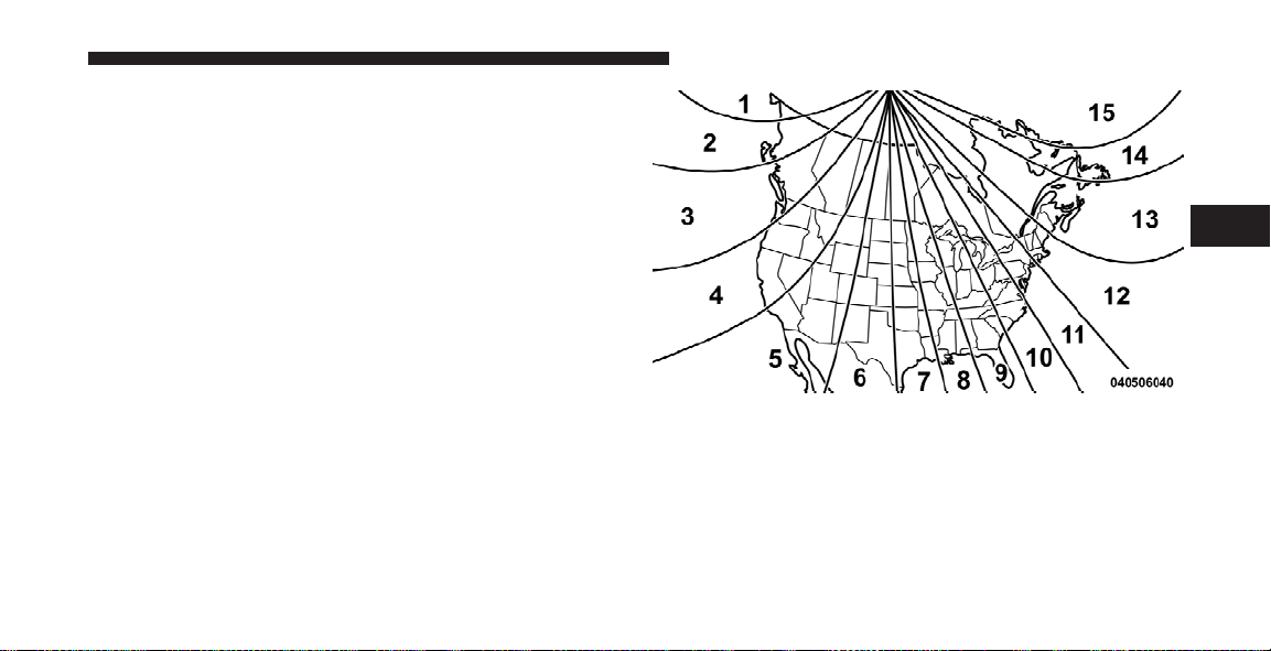
Compass Variance
Compass Variance is the difference between magnetic
North and Geographic North. In some areas of the
country, the difference between magnetic and geographic
North is great enough to cause the compass to give false
readings. If this occurs, the compass variance must be set
using the following procedure:
NOTE: Magnetic materials should be kept away from
the overhead console. This is where the compass sensor is
located.
UNDERSTANDING THE FEATURES OF YOUR VEHICLE 19
3
Compass Variance Map

20 UNDERSTANDING THE FEATURES OF YOUR VEHICLE
1. Turn the ignition switch to the ON/RUN position.
2. Press the MENU button until “Personal Settings” is
displayed.
3. Press the STEP button until “Compass Variance” is
displayed.
4. Press and release RESET button until the proper
variance zone is selected according to the map.
5. Press and release the Compass button to exit.

UNDERSTANDING YOUR INSTRUMENT PANEL
CONTENTS
䡵 Instrument Panel Features ................ 22
䡵 Instrument Cluster ..................... 23
▫ 6.7L Diesel Engine .................... 23
䡵 Instrument Cluster Description ............. 24
4

22 UNDERSTANDING YOUR INSTRUMENT PANEL
INSTRUMENT PANEL FEATURES
1 — Headlight Switch 6 — Passenger Airbag* 11 — TPMS “Light Load” Reset Switch* 16 — Transfer Case Control
2 — Air Outlets 7 — Glove Box 12 — Power Sliding Back Glass Switch* 17 — Parking Brake Release Lever
3 — Instrument Cluster 8 — Passenger Airbag On/
4 — Climate Controls 9 — Power Outlet 14 — Exhaust Brake Switch* * If Equipped
5 — Radio 10 — Heated Seat Switch 15 — Cigar Lighter
Off Switch*
13 — Cupholders 18 — Adjustable Pedal Control
Switch*
Switch*

INSTRUMENT CLUSTER
6.7L Diesel Engine
UNDERSTANDING YOUR INSTRUMENT PANEL 23
4

24 UNDERSTANDING YOUR INSTRUMENT PANEL
INSTRUMENT CLUSTER DESCRIPTION
1. Check Gages Warning Light
This light will illuminate when the voltmeter,
engine oil pressure, or engine coolant temperature
gauge indicates a reading either too high or too low.
Examine the gauges carefully, and follow the instructions
contained below for each indicated problem.
NOTE: When the ignition switch is turned to OFF, the
fuel gauge, voltmeter, oil pressure and engine coolant
temperature gauges may not show accurate readings.
When the engine is not running, turn the ignition switch
to ON to obtain accurate readings.
2. Voltmeter
When the engine is running, the gauge indicates
the electrical system voltage. The pointer should
stay within the normal range if the battery is charged. If
the pointer moves to either the extreme left or right, and
remains there during normal driving, the electrical system should be serviced.
NOTE:
•
If the gauge pointer moves to either extreme of the
gauge, the “Check Gages Warning Light” will illuminate and a single chime will sound.
•
The voltmeter may show a gauge fluctuation at various engine temperatures. This cycling operation is
caused by the post-heat cycle of the intake manifold
heater system. The number of cycles and the length of
the cycling operation is controlled by the engine
control module. Post-heat operation can run for several minutes, and then the electrical system and voltmeter needle will stabilize.
•
The cycling action will cause temporary dimming of
the headlights, interior lights, and also a noticeable
reduction in blower motor speed.
UNDERSTANDING YOUR INSTRUMENT PANEL 25
3. Turn Signal Indicator Light
The arrows will flash with the exterior turn signals
when the turn signal lever is operated.
4. Tachometer
The tachometer indicates engine speed in revolutions per
minute.
CAUTION!
Do not operate the engine with the tachometer
pointer at high RPM for extended periods. Engine
damage may occur.
5. Airbag Warning Light
The indicator lights and remains lit for six to
eight seconds when the ignition is first turned
on. If the light stays on, flickers or comes on
while driving, have the airbag system checked
by an authorized dealer.
6. High Beam Indicator Light
This indicator shows that headlights are on high
beam.
7. Seat Belt Reminder Light
When the ignition switch is first turned ON, this
light will turn on for five to eight seconds as a bulb
check. During the bulb check, if the driver’s seat
belt is unbuckled, a chime will sound. After the bulb
check or when driving, if the driver seat belt remains
unbuckled, the “Seat Belt Warning Light” will flash or
remain on continuously.
8. Speedometer
The speedometer shows the vehicle speed in miles per
hour (mph) and/or kilometers per hour (km/h).
4
26 UNDERSTANDING YOUR INSTRUMENT PANEL
9. Oil Pressure Gauge
The pointer should always indicate some oil pres-
sure when the engine is running. A continuous
high or low reading, under normal driving conditions,
may indicate a lubrication system malfunction. Immediate service should be obtained.
NOTE: If the gauge pointer moves to either extreme of
the gauge, the “Check Gages Warning Light” will illuminate and a single chime will sound.
10. Transfer Case Position Light
This display indicator shows the transfer case position
selection.
For additional information refer to “Four-Wheel Drive
Operation” in Section 5 of this manual.
11. TOW HAUL Indicator Light
The TOW HAUL button is located at the end of
the shift lever. This light will illuminate when
the TOW HAUL button is pushed once.
12. Temperature Gauge
The temperature gauge indicates engine coolant
temperature. Any reading within the normal
range indicates that the cooling system is operating satisfactorily. The gauge needle will likely indicate a
higher temperature when driving in hot weather, up
mountain grades, in heavy traffic, or when towing a
trailer. If the needle rises to the 245°F (118°C) mark, stop
the vehicle, shift into NEUTRAL, and increase the engine
idle speed for two to three minutes. If the temperature
reading does not return to normal, shut your engine OFF
and allow it to cool. Seek authorized service immediately.
Refer to “Cooling System” under “Maintaining Your
Vehicle” in Section 7.

UNDERSTANDING YOUR INSTRUMENT PANEL 27
CAUTION!
Do not leave your vehicle unattended with the engine running, as you would not be able to react to the
temperature indicator if the engine overheats.
NOTE:
•
Engine idle speed will automatically increase to 1,000
RPM at elevated coolant temperatures to improve
engine cooling.
•
If the gauge pointer moves to either extreme of the
gauge, the “Check Gages Warning Light” will illuminate and a single chime will sound.
13. Vehicle Security Light
The light will flash rapidly for approximately
16 seconds when the Vehicle Security Alarm is
arming. The light will flash at a slower rate
after the alarm is set. The “Vehicle Security Light” will
also come on for about two seconds when the ignition is
first turned ON.
14. Shift Lever Indicator (Automatic Transmissions
Only)
When the shift lever is moved (on vehicles with the
68RFE transmission), this indicator will show the selected
gear range (P R N D). Vehicles equipped with Auto-6/
Electronic Range Select (ERS) will display the selection of
the desired top gear, in the position next to the D (Drive).
15. Odometer/Trip Odometer
The odometer shows the total distance the vehicle has
been driven. U.S. federal regulations require that upon
transfer of vehicle ownership, the seller certify to the
purchaser the correct mileage that the vehicle has been
driven. Therefore, if the odometer reading is changed
during repair or replacement, be sure to keep a record of
the reading before and after the service so that the correct
mileage can be determined.
4

28 UNDERSTANDING YOUR INSTRUMENT PANEL
The two trip odometers show individual trip mileage. To
switch from odometer to trip odometers, press and
release the Trip Odometer button.
To reset a trip odometer, display the desired trip odometer to be reset then push and hold the button (approximately two seconds) until the display resets.
Vehicle Warning Messages
When the appropriate conditions exist, messages such as
“door” (indicates that a door(s) may be ajar), “gASCAP”
(which indicates that your gas cap is possibly loose or
damaged), and “noFUSE” (indicates that the IOD fuse is
removed from the Integrated Power Module), will display in the odometer.
NOTE: There is also an engine hour function. This
indicates the total number of hours the engine has been
running. To display the engine hours perform the following: Place the ignition in RUN, but do not start the
engine. With the odometer value displayed, hold the trip
button down for a period of six seconds. The odometer
will change to trip value first, then it will display the
engine hour value. The engine hours will be displayed
for a period of 30 seconds until the ignition is turned off
or the engine is started.
DPF Full
The messages “dPF” and “FULL” will alternately display
in the odometer when Diesel Particulate Filter (DPF)
service is required. Refer to “Overhead Console with
Electronic Vehicle Information Center (EVIC)” in Section 3 for more information.
16. Front Fog Light Indicator Light — If Equipped
This indicator will illuminate when the front fog
lights are on.

UNDERSTANDING YOUR INSTRUMENT PANEL 29
17. Malfunction Indicator Light (MIL)
The Malfunction Indicator Light (MIL) is part of
an onboard diagnostic system which monitors
the emissions and engine control system. If the
vehicle is ready for emissions testing the light will come
on when the ignition is first turned on and remain on, as
a bulb check, until the engine is started. If the vehicle is
not ready for emissions testing the light will come on
when the ignition is first turned on and remain on for
15 seconds, then blink for five seconds, and remain on
until the vehicle is started. If the bulb does not come on
during starting, have the condition investigated
promptly.
If this light comes on and remains on while driving, it
suggests a potential engine control problem and the need
for system service.
Although your vehicle will usually be drivable and not
need towing, see your authorized dealer for service as
soon as possible.
CAUTION!
•
Prolonged driving with the MIL on could cause
damage to the engine control system. It also could
affect fuel economy and drivability.
•
If the MIL is flashing, severe catalytic converter
damage and power loss will soon occur. Immediate service is required.
18. Brake Warning Light
This light monitors various brake functions,
including brake fluid level and parking brake
application. If the brake light turns on, it may
indicate that the parking brake is applied, that
the brake fluid level is low, or that there is a problem with
the anti-lock brake system reservoir.
If the light remains on when the parking brake has been
disengaged, and the fluid level is at the full mark on the
master cylinder reservoir, it indicates a possible brake
4

30 UNDERSTANDING YOUR INSTRUMENT PANEL
hydraulic system malfunction or a problem with the
Brake Booster has been detected by the Anti-Lock Brake
System (ABS) / Electronic Stability Program (ESP) system. In this case, the light will remain on until the
condition has been corrected. If the problem is related to
the brake booster, the ABS pump will run when applying
the brake and a brake pedal pulsation may be felt during
each stop.
The dual brake system provides a reserve braking capacity in the event of a failure to a portion of the hydraulic
system. A leak in either half of the dual brake system is
indicated by the “Brake Warning Light,” which will turn
on when the brake fluid level in the master cylinder has
dropped below a specified level.
The light will remain on until the cause is corrected.
NOTE: The light may flash momentarily during sharp
cornering maneuvers, which change fluid level conditions. The vehicle should have service performed, and
the brake fluid level checked.
If brake failure is indicated, immediate repair is necessary.
WARNING!
Driving a vehicle with the “Brake Warning Light” on
is dangerous. Part of the brake system may have
failed. It will take longer to stop the vehicle. You
could have an accident. Have the vehicle checked
immediately.
Vehicles equipped with the Anti-Lock Brake System
(ABS), are also equipped with Electronic Brake Force
Distribution (EBD). In the event of an EBD failure, the

UNDERSTANDING YOUR INSTRUMENT PANEL 31
“Brake Warning Light” will turn on along with the “ABS
Warning Light.” Immediate repair to the ABS system is
required.
Operation of the “Brake Warning Light” can be checked
by turning the ignition switch from the OFF position to
the ON position. The light should illuminate for approximately two seconds. The light should then turn off unless
the parking brake is applied or a brake fault is detected.
If the light does not illuminate, have the light inspected
by an authorized dealer.
The light also will turn on when the parking brake is
applied with the ignition switch in the ON position.
NOTE: This light shows only that the parking brake is
applied. It does not show the degree of brake application.
19. Anti-Lock Brake (ABS) Warning Light
This light monitors the Anti-Lock Brake System
(ABS). The light will turn on when the ignition
switch is turned to the ON position and may
stay on for as long as four seconds.
If the “ABS Warning Light” remains on or turns on while
driving, it indicates that the Anti-Lock portion of the
brake system is not functioning and that service is
required. However, the conventional brake system will
continue to operate normally if the “Brake Warning
Light” is not on.
If the “ABS Warning Light” is on, the brake system
should be serviced as soon as possible to restore the
benefits of Anti-Lock brakes. If the “ABS Warning Light”
does not turn on when the ignition switch is turned to the
ON position, have the light inspected by an authorized
dealer.
4

32 UNDERSTANDING YOUR INSTRUMENT PANEL
20. Cargo Light
The cargo light will illuminate when the cargo
lamp is activated by pressing the cargo light
button on the headlight switch.
21. Electronic Throttle Control (ETC) Warning Light
This light informs you of a problem with the
Electronic Throttle Control (ETC) system. If a
problem is detected, the light will come on
while the engine is running. If the light remains
lit with the engine running your vehicle will usually be
drivable, however, see your authorized dealer for service
as soon as possible. If the light is flashing when the
engine is running, immediate service is required and you
may experience reduced performance, an elevated/
rough idle or engine stall and your vehicle may require
towing. The light will come on when the ignition is first
turned on and remain on for 15 seconds as a bulb check.
If the light does not come on during starting, have the
system checked by an authorized dealer.
22. SERV 4WD Indicator Light
The “4WD” indicator will be illuminated
whenever the four-wheel drive mode is engaged on either the manual or electric shift
four-wheel drive systems. The “SERV 4WD
Indicator Light” monitors the electronic shift four-wheel
drive system. If the “SERV 4WD Indicator Light” stays on
or comes on while driving, it means that the four-wheel
drive system is not functioning properly and that service
is required.
23. Water In Fuel Indicator Light
Indicates there is water detected in the fuel
filter. If this light remains on, DO NOT start the
vehicle before you drain the water from the
fuel filter to prevent engine damage. Refer to
“Maintenance Procedures/ Draining Fuel/Water Separator Filter” in Section 7 for water drain procedure.

UNDERSTANDING YOUR INSTRUMENT PANEL 33
24. Tire Pressure Monitoring Telltale Light — If
Equipped
Each tire, including the spare (if provided),
should be checked monthly, when cold and
inflated to the inflation pressure recommended
by the vehicle manufacturer on the vehicle
placard or tire inflation pressure label. (If your vehicle
has tires of a different size than the size indicated on the
vehicle placard or tire inflation pressure label, you should
determine the proper tire inflation pressure for those
tires.)
As an added safety feature, your vehicle has been
equipped with a Tire Pressure Monitoring System
(TPMS) that illuminates a low tire pressure telltale when
one or more of your tires is significantly under-inflated.
Accordingly, when the low tire pressure telltale illuminates, you should stop and check your tires as soon as
possible, and inflate them to the proper pressure. Driving
on a significantly under-inflated tire causes the tire to
overheat and can lead to tire failure. Under-inflation also
reduces fuel efficiency and tire tread life, and may affect
the vehicle’s handling and stopping ability.
Please note that the TPMS is not a substitute for proper
tire maintenance, and it is the driver ’s responsibility to
maintain correct tire pressure, even if under-inflation has
not reached the level to trigger illumination of the TPMS
low tire pressure telltale.
4

34 UNDERSTANDING YOUR INSTRUMENT PANEL
Your vehicle has also been equipped with a TPMS
malfunction indicator to indicate when the system is not
operating properly. The TPMS malfunction indicator is
combined with the low tire pressure telltale. When the
system detects a malfunction, the telltale will flash for
approximately one minute and then remain continuously
illuminated. This sequence will continue upon subsequent vehicle start-ups as long as the malfunction exists.
When the malfunction indicator is illuminated, the system may not be able to detect or signal low tire pressure
as intended. TPMS malfunctions may occur for a variety
of reasons, including the installation of replacement or
alternate tires or wheels on the vehicle that prevent the
TPMS from functioning properly. Always check the
TPMS malfunction telltale after replacing one or more
tires or wheels on your vehicle, to ensure that the
replacement or alternate tires and wheels allow the TPMS
to continue to function properly.
CAUTION!
The TPMS has been optimized for the original
equipment tires and wheels. TPMS pressures and
warning have been established for the tire size
equipped on your vehicle. Undesirable system operation or sensor damage may result when using replacement equipment that is not of the same size,
type, and/or style. Aftermarket wheels can cause
sensor damage. Do not use tire sealant from a can, or
balance beads if your vehicle is equipped with a
TPMS, as damage to the sensors may result.

UNDERSTANDING YOUR INSTRUMENT PANEL 35
Tire Light Load Inflation Switch – If Equipped
The tire light load inflation switch allows you to choose
between “Light Load” vehicle conditions and “Max
Load” vehicle conditions, tire pressures, and related
TPMS warning levels. The switch is located on the
instrument panel, below the climate control panel. For
additional information, refer to “Tire Pressure Monitoring System (TPMS) — If Equipped” in Section 5 of this
manual.
25. Transmission Temperature Warning Light
(Automatic Transmissions Only)
This light indicates that there is excessive trans-
mission fluid temperature that might occur
with severe usage such as trailer towing. It may
also occur when operating the vehicle in a high
torque converter slip condition, such as four-wheel drive
operation (e.g., snow plowing, off-road operation). If this
light comes on, stop the vehicle and run the engine at idle
or faster, with the transmission in NEUTRAL until the
light goes off.
26. Wait To Start Light
The “Wait To Start Light” will illuminate when the
ignition is turned to the RUN position and the
intake manifold temperature is below 66°F (19°C). Follow
engine starting procedure for proper engine starting and
operating. Wait until the “Wait To Start Light” turns OFF,
then start the vehicle.
NOTE: The “Wait To Start Light” may not illuminate if
the intake manifold temperature is warm enough.
27. Odometer/Trip Odometer Button
Press this button to toggle between the odometer and the
trip odometer display. Holding the button in resets the
trip odometer reading when in trip mode.
4

36 UNDERSTANDING YOUR INSTRUMENT PANEL
28. Fuel Gauge
Shows level of fuel in tank when ignition switch is in the
ON position.
29. Low Fuel Warning Light
This light will illuminate when the pointer is between “E” and 1/8 indication mark (approximately
15% of tank volume) on the fuel gauge. When the
fuel gauge pointer is on “E” (equivalent to Distance To
Empty [DTE]=0ontheoverhead console, if so
equipped) there is reserve fuel capacity, which corresponds to approximately 8% of tank volume. This reserve
capacity was put in place to prevent the likelihood of
customers running out of fuel when operating at maximum load conditions in areas where there are not many
fuel stations.
30. CRUISE Indicator Light
This light will illuminate when the electronic
speed control system is turned on.

CONTENTS
STARTING AND OPERATING
䡵 Starting Procedures ..................... 39
▫ Manual Transmission – If Equipped ........ 39
▫ Automatic Transmission – If Equipped ...... 39
▫ Normal Starting Procedure –
Engine Manifold Air Temperature
Above 66°F (19°C) ..................... 40
▫ Starting Procedure – Engine Manifold Air
Temperature Below 66°F (19°C) ........... 41
▫ Starting Procedure – Engine Manifold Air
Temperature Below 0°F (-18°C) ............ 42
▫ Starting Fluids ....................... 44
䡵 Normal Operation – Diesel Engine .......... 44
▫ Cold Weather Precautions ............... 45
▫ Engine Idling ........................ 47
▫ Stopping The Engine ................... 48
▫ Engine Speed Control .................. 50
▫ Operating Precautions .................. 50
▫ Cooling System Tips – Automatic
Transmission ........................ 50
5

38 STARTING AND OPERATING
䡵 Engine Block Heater .................... 52
▫ Block Heater Usage .................... 52
䡵 Diesel Exhaust Brake (Engine Braking) –
If Equipped ........................... 53
䡵 Automatic Transmission — If Equipped ....... 54
▫ Automatic Transmission With Overdrive
(68RFE) — If Equipped (Ram Truck Only) .... 54
▫ Automatic Transmission With Overdrive
(AS68RC) – If Equipped (Chassis Cab Only)
... 60
䡵 Manual Transmission — If Equipped ......... 66
▫ Shifting ............................ 67
▫ Downshifting ........................ 68
▫ Reverse Shifting ...................... 69
䡵 Power Take Off Operation – If Equipped
(Chassis Cab Only) ...................... 70
▫ Stationary Mode ...................... 70
▫ Mobile Mode ........................ 71
▫ Power Take Off – Aftermarket Installation .... 72
䡵 Fuel Requirements ...................... 72
▫ Fuel Specifications .................... 73
䡵 Engine Runaway ....................... 74
䡵 Adding Fuel .......................... 74
▫ Fuel Filler Cap (Gas Cap) ............... 75
▫ Avoid Using Contaminated Fuel ........... 75
▫ Bulk Fuel Storage ..................... 76

STARTING AND OPERATING 39
STARTING PROCEDURES
Before starting your vehicle, adjust your seat, adjust both
inside and outside mirrors, and fasten your seat belts.
The starter should not be operated for more than 15second intervals. Waiting a few minutes between such
intervals will protect the starter from overheating.
WARNING!
Do not leave children or animals inside parked
vehicles in hot weather. Interior heat build up may
cause serious injury or death.
Manual Transmission – If Equipped
Apply the parking brake, place the shift lever in NEUTRAL and depress the clutch pedal to the floor before
starting the vehicle. This vehicle is equipped with a
clutch interlocking ignition system. It will not start unless
the clutch is fully depressed.
Automatic Transmission – If Equipped
Start the engine with the shift lever in NEUTRAL or
PARK position. Apply the brake before shifting to any
driving range.
The Cummins威 diesel engine is equipped with several
features designed to assist cold weather starting and
operation:
•
The engine block heater is a resistance heater installed
in the water jacket of the engine just above and behind
the oil filter. It requires a 110–115 Volt AC electrical
outlet with a grounded, three-wire extension cord.
NOTE: The engine block heater cord is a factory installed option. If your vehicle is not equipped, heater
cords are available from your authorized MOPAR威
dealer.
5

40 STARTING AND OPERATING
•
A 12–Volt heater built into the fuel filter housing aids
in preventing fuel gelling. It is controlled by a built-in
thermostat.
•
A heated intake air system both improves engine
starting and reduces the amount of white smoke
generated by a warming engine.
Normal Starting Procedure – Engine Manifold Air
Temperature Above 66°F (19°C)
Observe the instrument panel cluster lights when starting
the engine.
1. Always apply the parking brake.
2. Shift into PARK for an automatic transmission. For
vehicles equipped with a manual transmission, fully
depress and hold the clutch pedal and shift into NEUTRAL.
CAUTION!
If the “Water in Fuel Indicator Light” remains on, DO
NOT START the engine before you drain the water
from the fuel filter to avoid engine damage. Refer to
“Maintenance Procedures/Draining Fuel/Water Separator Filter” in Section 7 of this manual.
4. Turn the ignition key to START and crank the engine.
Do not press the accelerator during starting.
CAUTION!
Do not crank engine for more than 15 seconds at a
time or starter motor damage may result. Turn key to
OFF and wait at least two minutes for starter to cool
before repeating start procedure.
3. Turn the ignition key to the ON position and watch the
instrument panel cluster lights.
5. When the engine starts, release the key.

STARTING AND OPERATING 41
6. Check to see that there is oil pressure.
7. Release the parking brake.
Starting Procedure – Engine Manifold Air
Temperature Below 66°F (19°C)
NOTE: The temperature displayed on the overhead
console (if equipped) does not necessarily reflect the
engine manifold air temperature. When engine temperatures fall below 66°F (19°C) the “Wait To Start Light” will
remain on indicating the intake manifold heater system is
active.
Follow the steps in the “Normal Starting” procedure
except:
1. The “Wait To Start Light” will remain on for a period
of time (length of time depends on engine temperature).
CAUTION!
If the “Water in Fuel Indicator Light” remains on, DO
NOT START engine before you drain the water from
the fuel filter to avoid engine damage. Refer to
“Maintenance Procedures/Draining Fuel/Water Separator Filter” in Section 7 of this manual.
2. After the “Wait To Start Light” goes off, turn the
ignition key to START. Do not press the accelerator
during starting.
CAUTION!
Do not crank engine for more than 15 seconds at a
time or starter motor damage may result. Turn key to
OFF and wait at least two minutes for starter to cool
before repeating start procedure.
5

42 STARTING AND OPERATING
3. After engine start-up, check to see that there is oil
pressure.
4. Allow the engine to idle about three minutes until the
manifold heaters have completed the post-heat cycle.
5. Release the parking brake and drive.
NOTE:
•
Engine idle speed will automatically increase to 1,000
RPM at low coolant temperatures to improve engine
warm-up.
•
If the engine stalls, or if the ignition switch is left ON
for more than two minutes after the “Wait To Start
Light” goes out, reset the grid heaters by turning the
ignition switch to OFF for at least five seconds and
then back ON. Repeat steps 1 through 5 of “Starting
Procedure — Engine Manifold Air Temperature Below
66°F (19°C).”
Starting Procedure – Engine Manifold Air
Temperature Below 0°F (-18°C)
In extremely cold weather below 0°F (-18°C) it may be
beneficial to cycle the manifold heaters twice before
attempting to start the engine. This can be accomplished
by turning the ignition OFF for at least five seconds and
then back ON after the “Wait To Start Light” has turned
off, but before the engine is started. However, excessive
cycling of the manifold heaters will result in damage to
the heater elements or reduced battery voltage.
NOTE: If multiple pre-heat cycles are used before
starting, additional engine run time may be required to
maintain battery state of charge at a satisfactory level.
1. If the engine stalls after the initial start, the ignition
must be turned to the OFF position for at least five
seconds and then to the ON position to recycle the
manifold heaters.

STARTING AND OPERATING 43
NOTE: Excessive white smoke and poor engine performance will result if manifold heaters are not recycled.
2. Heat generated by the manifold heaters dissipates
rapidly in a cold engine. If more than two minutes pass
between the time the “Wait To Start Light” turns off and
the engine is started, recycle the manifold heaters by
turning the ignition OFF for at least five seconds and then
back ON.
3. If the vehicle is driven and vehicle speed exceeds
19 mph (31 km/h) before the manifold heater post-heat
(after start) cycle is complete, the manifold heaters will
shut off.
4. If the engine is started before the “Wait To Start Light”
turns off, the preheat cycle will turn off.
5. If the engine is cranked for more than 10 seconds, the
post-heat cycle will turn off.
NOTE:
•
Engine idle speed will automatically increase to 1, 000
RPM at low coolant temperatures to improve engine
warm-up.
•
When a diesel engine is allowed to run out of fuel or
the fuel gels at low temperatures, air is pulled into the
fuel system. If your engine has run out of fuel, refer to
“Adding Fuel/Priming If The Engine Has Run Out Of
Fuel” in this section.
5

44 STARTING AND OPERATING
Starting Fluids
WARNING!
Starting fluids or flammable liquids are never to be
used in the Cummins威 diesel engine (see Warning
label). Never pour diesel fuel, flammable liquid,
starting fluids (ether) into the air cleaner canister, air
intake piping, or turbocharger inlet in an attempt to
start the vehicle. This could result in a flash fire and
explosion causing serious personal injury and engine
damage.
The engine is equipped with an automatic electric air
preheating system. If the instructions in this manual are
followed, the engine should start in all conditions.
WARNING!
Do not leave children or animals inside parked
vehicles in hot weather. Interior heat build up may
cause serious injury or death.
NORMAL OPERATION – DIESEL ENGINE
Observe the following when the engine is operating.
•
All message center lights are off.
•
Malfunction Indicator Light (MIL) is off.
•
Engine oil pressure is above 10 psi (69 kPa) at idle.
•
Voltmeter operation:
•
The voltmeter may show a gauge fluctuation at
various engine temperatures. This cycling operation
is caused by the post-heat cycle of the intake manifold heater system. The number of cycles and the
length of the cycling operation is controlled by the

engine control module. Post-heat operation can run
for several minutes, and then the electrical system
and voltmeter needle will stabilize.
•
The cycling action will cause temporary dimming of
the headlamps, interior lamps, and also a noticeable
reduction in blower motor speed.
STARTING AND OPERATING 45
Cold Weather Precautions
Operation in ambient temperature below 32°F (0°C) may
require special considerations. The following charts suggest these options:
Fuel Operating Range
NOTE: Use “Ultra Low Sulfur Diesel Fuels” ONLY.
*No. 1 Ultra Low Sulfur Diesel Fuel should only be used
where extended arctic conditions (-10°F/-23°C) exist.
NOTE:
•
Use of Climatized Ultra Low Sulfur Diesel Fuel or
Number 1 Ultra Low Sulfur Diesel Fuel results in a
noticeable decrease in fuel economy.
•
Climatized Ultra Low Sulfur Diesel Fuel is a blend of
Number 2 Ultra Low Sulfur and Number 1 Ultra Low
Sulfur Diesel Fuels which reduces the temperature at
which wax crystals form in fuel.
5

46 STARTING AND OPERATING
•
The engine requires the use of “Ultra Low Sulfur
Diesel Fuel”. Use of incorrect fuel could result in
engine and exhaust system damage. Refer to” Fuel
Requirements” in Section 5.
Engine Oil Usage
Refer to “Maintenance Procedures” in Section 7 of this
manual for the correct engine oil viscosity.
Winter Front Usage
If a winter front or cold weather cover is to be used, a
percentage of the total grille opening area must be left
uncovered to provide sufficient air flow to the charge air
cooler and automatic transmission oil cooler. The percentage of opening must be increased with the increasing
ambient air temperature and/or engine load. If the
cooling fan can be heard cycling frequently, increase the
size of the opening in the winter front. A suitable cold
weather cover is available from your MOPAR威 dealer.
Battery Blanket Usage
A battery loses 60% of its cranking power as the battery
temperature decreases to 0°F (-18°C). For the same decrease in temperature, the engine requires twice as much
power to crank at the same RPM. The use of 120 VAC
powered battery blankets will greatly increase starting
capability at low temperatures. Suitable battery blankets
are available from your authorized MOPAR威 dealer.
Engine Warm-Up
Avoid full throttle operation when the engine is cold.
When starting a cold engine, bring the engine up to
operating speed slowly to allow the oil pressure to
stabilize as the engine warms up.
NOTE: High-speed, no-load running of a cold engine
can result in excessive white smoke and poor engine
performance. No-load engine speeds should be kept
under 1,200 RPM during the warm-up period, especially
in cold ambient temperature conditions.

STARTING AND OPERATING 47
Your vehicle is equipped with a turbo speed limiter, this
feature limits the engine speed to 1,200 RPM when
engine coolant temperatures are below 70°F (21°C). This
feature is designed to protect the turbo charger from
damage and will only operate in PARK or NEUTRAL.
If temperatures are below 32°F (0°C), operate the engine
at moderate speeds for five minutes before full loads are
applied.
NOTE:
•
If ambient temperatures are low and the coolant
temperature is below 180°F (82°C), the engine idle
speed will slowly increase to 1,000 RPM after two minutes of idle, if the following conditions are met:
•
foot is off brake pedal and throttle pedal
•
automatic transmission is in PARK
•
vehicle speed is zero
•
Applying the throttle will cancel fast idle
•
If the engine is equipped with an exhaust brake,
operating the exhaust brake at idle will greatly improve warm up rate and will help keep the engine
close to operating temperature during extended idle.
Engine Idling
Avoid prolonged idling, long periods of idling may be
harmful to your engine because combustion chamber
temperatures can drop so low that the fuel may not burn
completely. Incomplete combustion allows carbon and
varnish to form on piston rings, engine valves, and
injector nozzles. Also, the unburned fuel can enter the
crankcase, diluting the oil and causing rapid wear to the
engine.
If the engine is allowed to idle for extended periods, the
engine speed may increase for a period of time and then
return to normal idle speed.
5

48 STARTING AND OPERATING
CAUTION!
Extended periods of idle time may not allow the
vehicle’s exhaust aftertreatment system to properly
regenerate. This can lead to the illumination of the
Malfunction Indicator Light (MIL) or an Electronic
Vehicle Information Center (EVIC) warning message.
Operating the engine for extended periods with the
MIL illuminated or an EVIC warning message displayed can cause extensive engine and exhaust system damage.
NOTE: For EVIC messages related to the vehicle’s
exhaust system, refer to “Intervention Regeneration
Strategy — EVIC Message Process Flow” in Section 7 of
this manual.
An optional driver-controlled high idle speed is available
on automatic transmission equipped vehicles with speed
control. This feature allows the driver to select an elevated idle speed between 1,100 and 1,500 RPM. Your
dealer can enable this feature.
The optional driver-controlled high idle speed will help
increase cylinder temperatures and provide additional
cab heat, however, may still cause the exhaust aftertreatment system to not properly regenerate. Extended periods of idle time should be avoided.
Stopping The Engine
Idle the engine a few minutes before routine shutdown.
After full load operation, idle the engine three to five
minutes before shutting it down. This idle period will
allow the lubricating oil and coolant to carry excess heat
away from the combustion chamber, bearings, internal
components, and turbocharger. This is especially important for turbocharged, charge air-cooled engines.

STARTING AND OPERATING 49
NOTE:
•
During engine shut down on vehicles equipped with
manual transmissions, it is normal for the diesel
engine to resonate heavily for a moment during engine
shut off. When the engine is connected to a manual
transmission, this resonance causes load gear rattle
from the transmission. This is commonly referred to as
“shut down rattle.” The manufacturer recommends
performing engine shut down with the clutch pedal
pushed to the floor (clutch disengaged). When engine
shut down is performed in this manner the rattle is
reduced (not eliminated).
•
Refer to the following chart for proper engine
shutdown.
Driving
Condition
Stop and
Go
Stop and
Go
Highway
Speeds
City Traffic Maximum
Highway
Speeds
Uphill
Grade
Load
Empty Cool Less than
Medium One
Medium Warm Two
GCWR
Maximum
GCWR
Maximum
GCWR
Turbo-
charger
Temperature
Hot Five
Idle Time
(min.) Be-
fore Engine
Shutdown
One
5
Three
Four

50 STARTING AND OPERATING
Engine Speed Control
CAUTION!
Prevent overspeeding the engine going downhill.
When descending steep grades, use a combination of
gears and service brakes to control vehicle/engine
speed. Overspeed can cause severe engine damage.
Operating Precautions
Avoid Overheating The Engine
The temperature of the engine coolant (antifreeze) (a
mixture of 50% ethylene-glycol and 50% water) must not
exceed the normal range of the temperature gauge 240°F
(116°C) with a 16 psi (110 kPa) radiator cap.
Usually the engine coolant (antifreeze) temperature indicated during operation will be to the left of center in the
normal range of the gauge.
Avoid Low Coolant Temperature Operation
Continual operation at low engine coolant (antifreeze)
temperature below the normal range on the gauge 140°F
(60°C) can be harmful to the engine. Low engine coolant
(antifreeze) temperature can cause incomplete combustion which allows carbon and varnish to form on piston
rings and injector nozzles. Also, the unburned fuel can
enter the crankcase, diluting the lubricating oil and
causing rapid wear to the engine.
Cooling System Tips – Automatic Transmission
To reduce potential for engine and transmission overheating in high ambient temperature conditions, take the
following actions:
•
City Driving —
When stopped, put transmission in NEUTRAL and increase engine idle speed.
•
Highway Driving —
Reduce your speed.

•
Up Steep Hills —
Select a lower transmission gear, but try and keep the
torque converter clutch engaged.
•
Air Conditioning —
Turn it off temporarily.
Do Not Operate The Engine With Low Oil
Pressure
When the engine is at normal operating temperature, the
minimum oil pressures required are:
Idle 700 to 800 RPM ...............10psi(69kPa)
Full speed and load ..............30psi(207 kPa)
CAUTION!
If oil pressure falls to less than normal readings, shut
the engine off immediately. Failure to do so could
result in immediate and severe engine damage.
STARTING AND OPERATING 51
Do Not Operate The Engine With Failed Parts
Practically all failures give some warning before the parts
fail. Be on the alert for changes in performance, sounds,
and visual evidence that the engine requires service.
Some important clues are:
•
engine misfiring or vibrating severely
•
sudden loss of power
•
unusual engine noises
•
fuel, oil or coolant leaks
•
sudden change, outside the normal operating range, in
the engine operating temperature
•
excessive smoke
•
oil pressure drop
5

52 STARTING AND OPERATING
ENGINE BLOCK HEATER
The engine block heater warms engine coolant and
permits quicker starts in cold weather. Connect the heater
cord to a ground-fault interrupter protected 110–115 Volt
AC electrical outlet with a grounded, three-wire extension cord.
The engine block heater cord is routed under the hood to
the right side and can be located just behind the grille
near the headlamp.
NOTE: The engine block heater cord is a factory installed option. If your vehicle is not equipped, heater
cords are available from your authorized MOPAR威
dealer.
The block heater must be plugged in at least one hour to
have an adequate warming effect on the coolant.
WARNING!
Remember to disconnect the cord before driving.
Damage to the 110–115 Volt electrical cord could
cause electrocution.
NOTE: The block heater will require 110 Volts AC and
6.5 Amps to activate the heater element.
Block Heater Usage
For ambient temperatures below 0°F (-18°C), engine
block heater usage is recommended.
For ambient temperatures below –20°F (-29°C), engine
block heater usage is required.

STARTING AND OPERATING 53
DIESEL EXHAUST BRAKE (ENGINE BRAKING) –
IF EQUIPPED
The exhaust brake feature will only function when the
driver turns the exhaust brake switch to the ON position.
Exhaust Brake Switch
Once the switch is in the ON position and the vehicle is
moving faster than 5 mph (8 km/h); the exhaust brake
will automatically operate when the driver removes
pressure from the accelerator pedal. Exhaust braking is
most effective when the engine RPM is higher. The
automatic transmission has been programmed to downshift more aggressively when the exhaust brake is enabled to increase brake performance.
CAUTION!
Use of aftermarket exhaust brakes is not recommended and could lead to engine damage
WARNING!
Do not use the exhaust brake feature when driving in
icy or slippery conditions as the increased engine
braking can cause the rear wheels to slide and the
vehicle to swing around with the possible loss of
vehicle control, which may cause an accident possibly resulting in personal injury or death.
5

54 STARTING AND OPERATING
NOTE: For optimum braking power it is recommended
to use the exhaust brake while in TOW/HAUL Mode.
The purpose of the exhaust brake (engine braking) feature is to supply negative (braking) torque to the engine.
Typically, the engine braking is used for, but not limited
to, vehicle towing applications where vehicle braking can
be achieved by the internal engine power, thereby sparing the mechanical brakes of the vehicle.
Benefits of the exhaust brake are:
•
vehicle driving control
•
reduced brake fade
•
longer brake life
•
faster cab warm-up.
The exhaust brake feature can also be used to reduce the
engine warm up time. To use the exhaust brake as a
warm-up device, the vehicle must be stopped or moving
less than 5 mph (8 km/h), the exhaust brake switch must
be in the ON position, and the coolant temperature must
below 180°F (82°C) and ambient temperature below 60°F
(16°C).
AUTOMATIC TRANSMISSION — IF EQUIPPED
Automatic Transmission with Overdrive (68RFE)
— If Equipped (Ram Truck Only)
The shift lever display located in the instrument panel
cluster indicates the transmission gear range (the selector
is illuminated for night driving). The shift lever is
mounted on the right side of the steering column. You
must depress the brake pedal to pull the shift lever out of
PARK position (Brake Interlock System). To drive, move
the shift lever from PARK or NEUTRAL to the desired
DRIVE position. Pull the shift lever toward you when
shifting into REVERSE, SECOND, FIRST or PARK, or
when shifting out of PARK.

STARTING AND OPERATING 55
Gear Ranges
DO NOT race the engine when shifting from PARK or
NEUTRAL position into another gear range.
PARK
This gear position supplements the parking brake by
locking the transmission. The engine can be started in
this range. Never use PARK while the vehicle is in
motion. Apply the parking brake when leaving the
vehicle in this range. Always apply the parking brake
first, then place the shift lever into the PARK position. On
four-wheel drive vehicles be sure that the transfer case is
in a drive position.
WARNING!
•
Never use the PARK position as a substitute for
the parking brake. Always apply the parking
brake fully when parked to guard against vehicle
movement and possible injury or damage.
•
Your vehicle could move and injure you and others
if it is not completely in PARK. Check by trying to
move the shift lever back and forth without first
pulling it toward you after you have set it in
PARK. Make sure it is in PARK before leaving the
vehicle.
(Continued)
5

56 STARTING AND OPERATING
WARNING! (Continued)
•
It is dangerous to move the shift lever out of PARK
or NEUTRAL if the engine speed is higher than
idle speed. If your foot is not firmly on the brake
pedal, the vehicle could accelerate quickly forward
or in reverse. You could lose control of the vehicle
and hit someone or something. Only shift into
gear when the engine is idling normally and when
your foot is firmly on the brake pedal.
REVERSE
Use this range only after the vehicle has come to a
complete stop.
NEUTRAL
Shift into NEUTRAL when the vehicle is standing for
prolonged periods with the engine running. The engine
may be started in this range. Set the parking brake if you
must leave the vehicle.
DRIVE
Drive range provides underdrive 1st, 2nd and 3rd gears,
direct 4th gear and overdrive 5th and 6th gears. The shift
into overdrive 5th and 6th gear occurs only after the
transmission has completed the shift into 4th gear. No
other movement of the shift mechanism is required to
complete the 4–5 or 5–6 gear shifts.
The 4th and 5th gear upshifts occurs automatically unless
the TOW HAUL mode is enabled.
Upshifts into both overdrive gears, 5th and 6th, will be
delayed when the transmission fluid temperature is
below 40° F (4.5° C) or above 240° F (115.5° C).
NOTE: Use caution when operating a heavily loaded
vehicle in 2nd or 1st gear in high ambients as torque
converter slip can impose significant additional heat load
on the cooling system.

STARTING AND OPERATING 57
Overdrive Operation
The overdrive automatic transmission contains an electronically controlled 5th and 6th (Overdrive). The transmission will automatically shift from DRIVE to Overdrive if the following conditions are present:
•
the shift lever is in DRIVE;
•
the engine coolant has reached normal operating temperature;
•
vehicle speed is above approximately 30 mph
(48 km/h);
•
the “TOW HAUL O/D OFF” switch has not been
activated;
•
transmission has reached normal operating
temperature.
NOTE: If the vehicle is started in extremely cold temperatures, the transmission may not shift into Overdrive
and will automatically select the most desirable gear for
operation at this temperature. Normal operation will
resume when the transmission fluid temperature has
risen to a suitable level. Refer to the Note under “Torque
Converter Clutch” later in this section.
If the transmission temperature gets extremely hot, the
transmission will automatically select the most desirable
gear for operation at this temperature. If the transmission
temperature becomes hot enough the “Transmission
Temperature Warning Light” may illuminate and the
transmission may downshift out of Overdrive until the
transmission cools down. After cool down, the transmission will resume normal operation.
The transmission will downshift from Overdrive to
DRIVE if the accelerator pedal is fully depressed at
vehicle speeds above approximately 35 mph (56 km/h).
5

58 STARTING AND OPERATING
When To Use TOW HAUL
1 — Tow/Haul Switch
2 — AUTO-6 (ERS) Switch
When driving in hilly areas, towing a trailer, carrying a
heavy load, etc., and frequent transmission shifting occurs, press the TOW/HAUL switch once to select TOW
HAUL. In TOW HAUL mode, 4th to 5th gear upshifts are
delayed. Shifts into 5th and 6th gear are still allowed
under steady cruise conditions. Closed throttle downshifts (for improved engine braking) may occur during
steady braking maneuvers. Pressing the switch a second
time restores normal operation. Normal operation is
always the default at engine start-up.
The “TOW HAUL Indicator Light” will illuminate in the
instrument cluster to indicate when the switch has been
activated. If the TOW HAUL modes are desired, the
button must be pressed each time the engine is started.
Electronic Range Select (ERS) Operation
The Auto–6 Electronic Range Select (ERS) shift control
allows you to move the switch down (-) or up (+) when
the shifter is in the D (Drive) position, allowing the
selection of the desired top gear. For example, if the
driver shifts the transmission into 3rd gear, the transmission will never shift above 3rd gear, but can shift down to
2nd or 1st gear, when needed.

STARTING AND OPERATING 59
Switching from ERS to D-Mode can be done at any
vehicle speed. To switch from “Drive” mode to “ERS”
mode, press the switch down (-) once. The current gear
will be maintained as the top gear. To disable ERS, simply
press and hold the switch up (+) until “D” is displayed in
the instrument cluster odometer.
WARNING!
Do not downshift for additional engine braking on a
slippery surface. The drive wheels could lose their
grip and the vehicle could skid.
Screen Display 123456D
Actual Gear(s)
Allowed
NOTE: To select the proper gear position for maximum
deceleration (engine braking), simply press and hold the
switch down (-). The transmission will shift to the range
from which the vehicle can best be slowed down.
1 1-2 1-3 1-4 1-5 1-6 1-6
Torque Converter Clutch
A feature designed to improve fuel economy has been
included in the automatic transmission on your vehicle.
A clutch within the torque converter engages automatically at calibrated speeds. This may result in a slightly
different feeling or response during normal operation in
the upper gears. When the vehicle speed drops or during
acceleration when the transmission downshifts to second
gear, the clutch automatically disengages.
NOTE:
•
The torque converter clutch will not engage until the
transmission fluid and engine coolant are warm [usually after 1-3 miles (1.6 - 4.8 km) of driving]. Because
the engine speed is higher when the torque converter
clutch is not engaged, it may seem as if the transmission is not shifting into Overdrive when cold. This is
normal. Pressing the TOW HAUL O/D OFF button,
5

60 STARTING AND OPERATING
when the transmission is sufficiently warm, will demonstrate that the transmission is able to shift into and
out of Overdrive.
•
If the vehicle has not been driven in several days, the
first few seconds of operation after shifting the transmission into gear may seem sluggish. This is due to the
fluid partially draining from the torque converter into
the transmission. This condition is normal and will not
cause damage to the transmission. The torque converter will refill within five seconds of shifting from
PARK into any other gear position.
Automatic Transmission with Overdrive (AS68RC)
– If Equipped (Chassis Cab Only)
The shift lever display located in the instrument panel
cluster, indicates the transmission gear range (the selector
is illuminated for night driving). The shift lever is
mounted on the right side of the steering column. You
must depress the brake pedal, to pull the shift lever out of
PARK position (Brake Interlock System). To drive, move
the shift lever from PARK or NEUTRAL to the desired
drive position. Pull the shift lever toward you when
shifting into REVERSE, SECOND, FIRST or PARK, or
when shifting out of PARK.
Gear Ranges
DO NOT race the engine when shifting from PARK or
NEUTRAL position into another gear range.
PARK
This gear position supplements the parking brake by
locking the transmission. The engine can be started in
this range. Never use PARK while the vehicle is in
motion. Apply the parking brake when leaving the
vehicle in this range. Always apply parking brake first,
then place the shift lever in PARK position. On fourwheel drive vehicles be sure that the transfer case is in a
drive position.

STARTING AND OPERATING 61
WARNING!
•
Never use the PARK position as a substitute for
the parking brake. Always apply the parking
brake fully when parked to guard against vehicle
movement and possible injury or damage.
•
Your vehicle could move and injure you and others
if it is not completely in PARK. Check by trying to
move the shift lever back and forth without first
pulling it toward you after you have set it in
PARK. Make sure it is in PARK before leaving the
vehicle.
(Continued)
WARNING! (Continued)
•
It is dangerous to move the shift lever out of PARK
or NEUTRAL if the engine speed is higher than
idle speed. If your foot is not firmly on the brake
pedal, the vehicle could accelerate quickly forward
or in reverse. You could lose control of the vehicle
and hit someone or something. Only shift into
gear when the engine is idling normally and when
your right foot is firmly on the brake pedal.
5

62 STARTING AND OPERATING
REVERSE
Use this range only after the vehicle has come to a
complete stop.
NEUTRAL
Shift into NEUTRAL when the vehicle is standing for
prolonged periods with the engine running. The engine
may be started in this range. Set the parking brake if you
must leave the vehicle.
DRIVE
This position provides all forward gears, including 4th
gear direct and 5th or 6th (if equipped) gear overdrive
(refer to Overdrive Operation, in this section). Use this
range for most city and highway driving.
THIRD
Use this position for driving in slight heavy city traffic or
on mountain roads where more precise speed control is
desirable. Use it when climbing long grades, and for
engine braking when descending moderately steep
grades. To prevent excessive engine speed do not exceed
40 mph (64 km/h) in this range.
SECOND
Use this position for driving in more severe conditions
and lower speeds than THIRD. To prevent excessive
engine speed do not exceed 25 mph (40 km/h) in this
range.
FIRST
Use this position for driving up very steep hills and for
engine braking at low speeds 12 mph (19 km/h) or less
when going downhill. To prevent excessive engine speed,
do not exceed 12 mph (19 km/h) in this range.
NOTE: Use caution when operating a heavily loaded
vehicle in SECOND or FIRST gear selections in high
ambients as torque converter slip can impose significant
additional heat load on the cooling system.

STARTING AND OPERATING 63
Overdrive Operation
The Overdrive automatic transmission contains an electronically controlled 5th and 6th (if equipped) speed
(Overdrive). The transmission will automatically shift
from DRIVE to Overdrive if the following conditions are
present:
•
the shift lever is in DRIVE;
•
the engine coolant has reached normal operating temperature;
•
vehicle speed is above approximately 38 mph
(61 km/h) for 5th gear and 50 mph (80 km/h) for 6th
gear;
•
the “TOW HAUL O/D OFF” switch has not been
activated;
•
transmission has reached normal operating
temperature.
NOTE: If the vehicle is started in extremely cold temperatures, the transmission shift schedule initially restricts transmission operation in forward gear ranges to
3rd gear until the transmission fluid temperature rises to
a suitable level. During this condition, the ability of the
vehicle to accelerate under heavily loaded conditions
may be reduced. Refer to the “Note” under “Torque
Converter Clutch” in this section.
If the transmission temperature gets extremely hot, the
transmission will automatically select the most desirable
gear for operation at this temperature. If the transmission
temperature becomes hot enough, the “Transmission
Temperature Warning Light” may illuminate and the
transmission may downshift out of Overdrive until the
transmission cools down. After cool down, the transmission will resume normal operation.
The transmission will downshift from Overdrive to Drive
if the accelerator pedal is fully depressed at vehicle
5

64 STARTING AND OPERATING
speeds above approximately 35 to 40 mph (57 to
65 km/h) for 6th to 5th and 22 to 25 mph (36 to 40 km/h)
for 5th to 4th.
When To Use “TOW HAUL” and “O/D OFF”
Modes
When driving in hilly areas, towing a trailer, carrying a
heavy load, etc., and frequent transmission shifting occurs, press the “TOW HAUL O/D OFF” switch once to
select TOW HAUL. This will improve performance and
reduce the potential for transmission overheating or
failure due to excessive shifting. When operating in
“TOW HAUL” mode, 6th gear (if equipped) is disabled
and 2-3 and 3-4 and 4–5 shift patterns are modified. Shifts
into Overdrive (5th gear) are allowed during steady
cruise (for improved fuel economy). Pressing the “TOW
HAUL O/D OFF” switch a second time to select O/D
OFF will disable 5th and 6th gear completely, which
should eliminate any excessive transmission shifting.
Tow Haul O/D Off Switch
The “TOW HAUL” or “O/D OFF” Indicator Light will
illuminate in the instrument cluster to indicate when the
switch has been activated. Pressing the switch a third
time restores normal operation. If the “TOW HAUL” or
“O/D OFF” modes are desired, the switch must be
pressed each time the engine is started.

STARTING AND OPERATING 65
WARNING!
Do not use the Tow Haul feature when driving in icy
or slippery conditions. The increased engine braking
can cause the rear wheels to slide, and the vehicle to
swing around with the possible loss of vehicle control, which may cause an accident possibly resulting
in personal injury or death.
When To Lock Out Overdrive
When driving in hilly areas, towing a trailer, carrying a
heavy load, etc., and frequent 6–5–6 or 5–4–5 transmission shifting occurs, press the “TOW HAUL” switch. This
will improve performance and reduce the potential for
transmission overheating or failure due to excessive
shifting.
Torque Converter Clutch
A feature designed to improve fuel economy has been
included in the automatic transmission on your vehicle.
A clutch within the torque converter engages automatically at calibrated speeds. This may result in a slightly
different feeling or response during normal operation in
high gear. When the vehicle speed drops or during
acceleration when the transmission downshifts to 1st
gear, the clutch automatically disengages.
NOTE:
•
The torque converter clutch will not engage until the
transmission fluid and engine coolant are warm [usually after 1-3 miles (1.6 - 4.8 km) of driving]. Because
the engine speed is higher when the torque converter
clutch is not engaged, it may seem as if the transmission is not shifting into Overdrive when cold. This is
normal. Pressing the “TOW HAUL” switch when the
transmission is sufficiently warm will demonstrate
that the transmission is able to shift into and out of
Overdrive.
5

66 STARTING AND OPERATING
•
If the vehicle has not been driven in several days, the
first few seconds of operation after shifting the transmission into gear may seem sluggish. This is due to the
fluid partially draining from the torque converter into
the transmission. This condition is normal and will not
cause damage to the transmission. The torque converter will refill within five seconds of shifting from
PARK into any other gear position.
MANUAL TRANSMISSION — IF EQUIPPED
WARNING!
You or others could be injured if you leave the
vehicle unattended without having the parking
brake fully applied. The parking brake should always be applied when the driver is not in the vehicle,
especially on an incline.
CAUTION!
Never drive with your foot resting on the clutch
pedal, or attempt to hold the vehicle on a hill with the
clutch pedal partially engaged, as this will cause
abnormal wear on the clutch.
NOTE: During cold weather, you may experience in-
creased effort in shifting until the transmission fluid
warms up. This is normal.

STARTING AND OPERATING 67
Shifting
Shift Pattern
Truck models with manual transmission are equipped
with a clutch interlocking ignition system. The clutch
pedal must be fully depressed to start the vehicle.
Fully depress the clutch pedal before shifting gears. As
you release the clutch pedal, lightly depress the accelerator pedal.
This transmission has a “creeper” 1st gear (L=low) which
should be used to start from a standing position when
carrying a payload or towing a trailer. Damage to the clutch
can result from starting in 2nd or 3rd gear with a loaded
vehicle. An unloaded vehicle may be launched in 2nd gear.
Use each gear in numerical order – do not skip a gear.
You should use 1st gear when starting from a standing
position if under heavy load or when pulling a trailer.
Recommended Vehicle Shift Speeds
To utilize your manual transmission efficiently for both
fuel economy and performance, it should be upshifted as
listed in recommended shift speed chart. Shift at the
vehicle speeds listed for acceleration. When heavily
loaded or pulling a trailer these recommended up-shift
speeds may not apply.
5

68 STARTING AND OPERATING
Maximum Recommended Up-shift Speeds
Gear
Selec-
Lto2 2to3 3to4 4to5 5to6
tion
Maxi-
mum
Speed
7 mph
(11
km/h)
15 mph
(24
km/h)
25 mph
(40
km/h)
40 mph
(64
km/h)
45 mph
(72
km/h)
Downshifting
Moving from a high gear down to a lower gear is
recommended to preserve brakes when driving down
steep hills. In addition, downshifting at the right time
provides better acceleration when you desire to resume
speed. Downshift progressively. Do not skip gears to
avoid overspeeding the engine and clutch.
WARNING!
Do not downshift for additional engine braking on a
slippery surface. The drive wheels could lose their
grip and the vehicle could skid.
CAUTION!
When descending a hill, be very careful to downshift
one gear at a time to prevent overspeeding the engine
which can cause valve damage, and / or clutch disc
damage even if the clutch pedal is depressed.

STARTING AND OPERATING 69
Maximum Recommended Downshift Speeds
CAUTION!
Failure to follow the recommended downshifting
speeds may cause the engine to overspeed and/or
damage the clutch disc even if the clutch pedal is
depressed.
Maximum Recommended Downshifting Speeds
Gear
Selec-
tion
Maximum
Speed
6to5 5to4 4to3 3to2 2toL
68 mph
(109
km/h)
50 mph
(80
km/h)
32 mph
(51
km/h)
19 mph
(31
km/h)
10 mph
(16
km/h)
Reverse Shifting
To shift into REVERSE (R), bring the vehicle to a complete stop. Depress the clutch and pause briefly to allow
the gear train to stop rotating. Beginning from the
NEUTRAL (N) position, move the shift lever in one quick
smooth motion straight across and into the REVERSE (R)
area (the driver will feel a firm “click” as the shifter
passes the “knock-over”). Complete the shift by pulling
the shift lever into REVERSE (R).
5
The “knock-over” prevents the driver from accidentally
entering the REVERSE (R) shift area and warns the driver
that they are about to shift the transmission into REVERSE (R). Due to this feature, a slow shift to REVERSE
(R) can be perceived as a high shift effort.
To shift out of REVERSE bring the vehicle to a complete
stop and depress the clutch. Shifting out of REVERSE
prior to a complete stop may cause high shift effort.

70 STARTING AND OPERATING
POWER TAKE OFF OPERATION – IF EQUIPPED
(CHASSIS CAB ONLY)
This vehicle when equipped with either the automatic
six-speed or manual G-56 six-speed transmissions, will
allow for an aftermarket upfit with a transmission driven
PTO (power take off). The customer will have the ability
to operate the PTO in either a “stationary” or “mobile”
mode. The vehicles will be factory set to the “stationary”
mode. In order to select the “mobile” mode an authorized
dealership is required to modify the vehicle’s settings
using their proprietary authorized dealer service tool.
Stationary Mode
To operate the PTO in this mode the vehicle must meet
the following conditions:
•
Be in PARK position (vehicles equipped with automatic transmission)
•
Upfitter provider (on/off) switch has been activated
•
Parking brake applied (vehicles equipped with
manual transmission)
•
Vehicle engine must be running
•
No vehicle, brake or clutch switch faults present
•
PTO must be correctly installed using the vehicle
provided circuits
The customer has the choice to operate the PTO by
utilizing the cruise control switches or by utilizing a
remote control (provided by the PTO supplier). To operate the feature using the cruise control switches, the
customer must first activate the upfitter-provided on/off
switch. Next, the cruise control ON switch is selected.
Following this step the SET switch must be depressed.
The vehicle is now in the PTO mode and is ready for use.
In order to increase or decrease the engine idle speed, to
optimize the PTO function, the RESUME/ACCEL and
DECEL cruise switches can be used respectively. To

STARTING AND OPERATING 71
disengage PTO operation and return to “standard vehicle
operation” simply turn the upfitter-provided on/off
switch to the OFF position or press the CANCEL cruise
switch.
To operate the PTO via a remote switch the customer
must make sure the above conditions are met. It is vital
for proper operation that the PTO and remote have been
installed correctly, paying special attention to ensure the
vehicle provided wiring has been connected properly.
This is the responsibility of the installer of the PTO and
switches/remote system. It is the responsibility of the
PTO manufacturer to ensure that their electrical (switches
and remote) system is compatible with the vehicle’s
electrical architecture and software functionality.
Mobile Mode
To operate the PTO in this mode the vehicle must meet
the following conditions:
•
Authorized dealer-selected “mobile” mode activated
via authorized dealer proprietary service tool
•
Upfitter-provided (on/off) switch has been activated
•
Vehicle must be in PARK or DRIVE position (vehicles
equipped with automatic transmission)
•
Parking brake must not be applied
•
No vehicle, brake or clutch switch faults present
•
Vehicle engine must be running
•
PTO must be correctly installed using the vehicle
provided circuits
5

72 STARTING AND OPERATING
The customer may choose to use the PTO while the
vehicle is moving. To do so, the PTO function must be
activated prior to taking the vehicle out of PARK. This is
accomplished by activating the upfitter-provided PTO
on/off switch. At this point, the customer may place the
vehicle in a forward or reverse gear and have PTO
operation. To disengage PTO operation and return to
“standard vehicle operation” simply turn the upfitterprovided on/off switch to the OFF position.
NOTE: For application specific information with respect
to PTO and pump requirements and additional vehicle
information (wiring schematics, preset idle values, engine speed limits, and vehicle hardware and software
requirements) please refer to the Dodge Body Builders
Guide by accessing “www.dodge.com/bodybuilder” and
choosing the appropriate links.
Power Take Off – Aftermarket Installation
If you did not order the PTO (Power Take Off) Prep
Package from the factory and want to convert your
vehicle, refer to the Body Builders Guide at
www.dodge.com/bodybuilder or contact the manufacturer directly at dodgebbg@dcx.com (e-mail), 866–205–
4102 (toll free) or 313–493–2020.
FUEL REQUIREMENTS
Use good quality diesel fuel from a reputable supplier in
your vehicle. Federal law requires that you must fuel this
vehicle with Ultra Low Sulfur Highway Diesel fuel (15
ppm Sulfur maximum) and prohibits the use of Low
Sulfur Highway Diesel fuel (500 ppm Sulfur maximum)
to avoid damage to the emissions control system. For
most year-round service, No. 2 diesel fuel meeting ASTM
specification D-975 Grade S15 will provide good performance. If the vehicle is exposed to extreme cold (below
20°F or -7°C), or is required to operate at colder-thannormal conditions for prolonged periods, use climatized

STARTING AND OPERATING 73
No. 2 diesel fuel or dilute the No. 2 diesel fuel with 50%
No. 1 diesel fuel. This will provide better protection from
fuel gelling or wax-plugging of the fuel filters.
WARNING!
Do not use alcohol or gasoline as a fuel blending
agent. They can be unstable under certain conditions
and hazardous or explosive when mixed with diesel
fuel.
Diesel fuel is seldom completely free of water. To prevent
fuel system trouble, drain the accumulated water from
the fuel/water separator using the fuel/water separator
drain provided. If you buy good quality fuel and follow
the cold weather advice above, fuel conditioners should
not be required in your vehicle. If available in your area,
a high cetane “premium” diesel fuel may offer improved
cold-starting and warm-up performance.
Fuel Specifications
The Cummins威 diesel engine has been developed to take
advantage of the high energy content and generally
lower cost No. 2 Ultra Low Sulfur diesel fuel or No. 2
Ultra Low Sulfur climatized diesel fuels. Experience has
shown that it also operates on No. 1 Ultra Low Sulfur
diesel fuels or other fuels within specification.
NOTE:
•
A maximum blend of 5% biodiesel meeting ASTM
specification D-6751 may be used with your Cummins威 diesel engine.
•
In addition, commercially available fuel additives are
not necessary for the proper operation of your Cummins威 diesel engine.
•
No. 1 Ultra Low Sulfur diesel fuel should only be used
where extended arctic conditions (-10°F or -23°C) exist.
5

74 STARTING AND OPERATING
ENGINE RUNAWAY
WARNING!
In case of engine runaway due to flammable fumes
from gasoline spills or turbocharger oil leaks being
sucked into the engine, do the following to help
avoid personal injury and/or vehicle damage:
1. Shut off engine ignition switch.
2. Using a CO
guisher, direct the spray from the fire extinguisher
into the grille on the passenger side so that the spray
enters the engine air intake.
The inlet for the engine air intake is located behind
the passenger side headlamp and receives air
through the grille.
or dry chemical type fire extin-
2
ADDING FUEL
CAUTION!
To avoid fuel spillage and overfilling, do not “top
off” the fuel tank after filling.
NOTE:
•
When the fuel nozzle “clicks” or shuts off, the fuel
tank is full.
•
Tighten the gas cap until you hear a “clicking” sound.
This is an indication that the gas cap is properly
tightened.
•
Make sure that the gas cap is tightened each time the
vehicle is refueled.

STARTING AND OPERATING 75
WARNING!
A fire may result if fuel is pumped into a portable
container that is on a truck bed. You could be burned.
Always place fuel containers on the ground while
filling.
Fuel Filler Cap (Gas Cap)
If the gas cap is lost or damaged, be sure the replacement
cap is for use with this vehicle.
CAUTION!
Damage to the fuel system or emission control system could result from using an improper fuel tank
filler tube cap (gas cap). A poorly fitting cap could let
impurities into the fuel system.
WARNING!
•
Never have any smoking materials lit in or near
the vehicle when the gas cap is removed or the
tank filled.
•
Never add fuel to the vehicle when the engine is
running.
Avoid Using Contaminated Fuel
Fuel that is contaminated by water or dirt can cause
severe damage to the engine fuel system. Proper maintenance of the engine fuel filter and fuel tank is essential.
Refer to “Maintenance Procedures” in Section 7 of this
manual.
5

76 STARTING AND OPERATING
Bulk Fuel Storage
If you store quantities of fuel, good maintenance of the
stored fuel is also essential. Fuel contaminated with
water will promote the growth of “microbes.” These
microbes form “slime” that will clog fuel filters and lines.
Drain condensation from the supply tank and change the
line filter on a regular basis.
NOTE: When a diesel engine is allowed to run out of
fuel, air is pulled into the fuel system.
If the vehicle will not start, refer to “Maintenance
Procedures/Priming If The Engine Has Run Out Of Fuel”
in Section 7 of this manual.
WARNING!
Do not open the high pressure fuel system with the
engine running. Engine operation causes high fuel
pressure. High pressure fuel spray can cause serious
injury or death.

WHAT TO DO IN EMERGENCIES
CONTENTS
䡵 Jump-Starting ........................ 78
▫ With Portable Starting Unit ............. 81
6

78 WHAT TO DO IN EMERGENCIES
JUMP-STARTING
WARNING!
•
To prevent personal injury or damage to clothing,
do not allow battery fluid to contact eyes, skin or
fabrics. Do not lean over a battery when connecting jumper cables or allow cable clamps to touch
each other. Keep open flames or sparks away from
battery vent holes. Always wear eye protection
when working with batteries.
•
Do not use a booster battery or any other booster
source that has a greater than 12-Volt system, i.e.,
do not use a 24-Volt power source.
NOTE: Replacement batteries should both be of equal
size to prevent damage to the vehicle’s charging system.
Your vehicle is equipped with two 12-Volt batteries. If it
becomes necessary to use a booster battery with jumper
cables to start a vehicle’s engine because its batteries are
discharged, the following procedure should be used:
Set the parking brake and place an automatic transmission in PARK (or NEUTRAL for a manual transmission).
Turn off lights, heater and other electrical loads. Observe
charge indicator (if equipped) in both batteries. If the
indicator (if equipped) is light or yellow on either battery,
replace that battery.
CAUTION!
Use the jump-start procedure only when the charge
indicator (if equipped) in both batteries is dark in the
center. Do not attempt jump-starting when either
battery charge indicator (if equipped) is bright or
yellow. If the charge indicator (if equipped) has a
green dot in the center, failure to start is not due to a
discharged battery and cranking system should be
checked.

1. Attach one jumper cable to the positive terminal of
booster battery and the other end of the same cable to the
positive terminal of the discharged battery.
WARNING!
Do not permit vehicles to touch each other as this
could establish a ground connection and personal
injury could result.
WHAT TO DO IN EMERGENCIES 79
6
Attaching Booster Cables
1 — Discharged Battery
2 — Booster Battery

80 WHAT TO DO IN EMERGENCIES
2. Connect one end of the other jumper cable to negative
(-) post of booster battery. Connect the other end of the
jumper cable to a good ground on the engine block of the
vehicle with the discharged battery. Make sure a good
connection is made, free of dirt and grease.
WARNING!
•
Do not connect the cable to the negative post of the
discharge battery. The resulting electrical spark
could cause the battery to explode.
•
During cold weather when temperatures are below freezing point, electrolyte in a discharged
battery may freeze. Do not attempt jump-starting
because the battery could rupture or explode. The
battery temperature must be brought up above
freezing point before attempting to jump-start.
3. Take care that the clamps from one cable do not
inadvertently touch clamps from the other cable. Do not
lean over the battery when making connection. The
negative connection must provide good electrical conductivity and current carrying capacity.
4. After the engine is started or if the engine fails to start,
cables must be disconnected in the following order:
a. Disconnect the negative cable at the engine ground.
b. Disconnect the negative cable at the negative post
on booster battery.
c. Disconnect the cable from the positive post of both
batteries.

WHAT TO DO IN EMERGENCIES 81
WARNING!
Any procedure other than above could result in:
•
Personal injury caused by electrolyte squirting out
the battery vent;
•
Personal injury or property damage due to battery
explosion;
•
Damage to charging system of booster vehicle or
of immobilized vehicle.
With Portable Starting Unit
There are many types of these units available. Follow the
manufacturer’s instructions for necessary precautions
and operation.
CAUTION!
It is very important that the starting unit operating
voltage does not exceed 12-Volts DC or damage to
battery, starter motor, alternator, or electrical system
may occur.
6


CONTENTS
MAINTAINING YOUR VEHICLE
䡵 Engine Compartment — 6.7L Diesel ......... 85
䡵 Maintenance Procedures .................. 86
▫ Engine Oil .......................... 86
▫ Engine Air Cleaner Filter ................ 90
▫ Draining Fuel/Water Separator Filter ....... 92
▫ Priming If The Engine Has Run
Out Of Fuel ......................... 95
▫ Intervention Regeneration Strategy –
EVIC Message Process Flow .............. 96
▫ Maintenance-Free Batteries .............. 99
▫ Cooling System ..................... 100
▫ Charge Air Cooler — Inter-Cooler ........ 105
▫ Brake System ....................... 106
▫ Clutch Hydraulic System ............... 107
▫ Transfer Case — If Equipped ............ 107
▫ Manual Transmission — If Equipped ...... 107
7

84 MAINTAINING YOUR VEHICLE
▫ Automatic Transmission — If Equipped . . . 108
▫ Noise Control System Required Maintenance
& Warranty ........................ 112
䡵 Fluid Capacities ..................... 116
䡵 Fluids, Lubricants And Genuine Parts ...... 117
▫ Engine ........................... 117
▫ Chassis .......................... 119

MAINTAINING YOUR VEHICLE 85
ENGINE COMPARTMENT — 6.7L DIESEL
1 — Battery 8 — Washer Fluid Reservoir
2 — Engine Oil Fill 9 — Integrated Power Module
3 — Engine Oil Dipstick 10 — Engine Coolant Reservoir
4 — Automatic Transmission Dipstick 11 — Power Steering Fluid Reservoir
5 — Brake Fluid Reservoir 12 — Coolant Pressure Cap
6 — Clutch Master Cylinder (Manual Transmission Only) 13 — Air Cleaner Filter
7 — Battery
7

86 MAINTAINING YOUR VEHICLE
MAINTENANCE PROCEDURES
The pages that follow contain the required maintenance
services determined by the engineers who designed your
vehicle.
Besides the maintenance items for which there are fixed
maintenance intervals, there are other items that should
operate satisfactorily without periodic maintenance.
However, if a malfunction of these items does occur, it
could adversely affect the engine or vehicle performance.
These items should be inspected if a malfunction is
observed or suspected.
Engine Oil
Checking Oil Level
To assure proper lubrication of your vehicle’s engine, the
engine oil must be maintained at the correct level. Check
the oil level at regular intervals. The best time to check
the oil level is before starting the engine after it has been
parked overnight. When checking oil after operating the
engine, first ensure the engine is at full operating temperature, then wait for 30 minutes after engine shutdown
to check the oil.
1 — ADD Range
2—FullMark
3 — SAFE Range

MAINTAINING YOUR VEHICLE 87
Checking the oil while the vehicle is on level ground will
improve the accuracy of the oil level readings. Add oil
only when the level on the dipstick is below the “ADD”
mark. The total capacity from the low mark to the high
mark is 2 qts (1.9L).
CAUTION!
Overfilling or underfilling the crankcase will cause
oil aeration or loss of oil pressure. This could damage
your engine.
Never operate the engine with oil level below the “ADD”
mark or above the upper “SAFE” mark.
Change Engine Oil
Refer to “Oil Change Required” under “Overhead Console with Electronic Vehicle Information Center/System
Status (EVIC Displays)” in Section 3 of this manual for
recommended engine oil change intervals.
Engine Oil Selection
For best performance and maximum protection under all
types of operating conditions, the manufacturer only
recommends engine oils that are API CJ-4 certified and
meet the requirements of Chrysler LLC. Use MOPAR威 or
an equivalent oil meeting Chrysler Material Standard
MS-10902. Products meeting Cummins威 CES 20081 may
also be used. The identification of these engine oils are
typically located on the back of the oil container.
American Petroleum Institute (API) Engine Oil
Identification Symbol
This symbol means that the oil has
been certified by the American Petroleum Institute (API). The manufacturer only recommends API Certified
engine oils.
7

88 MAINTAINING YOUR VEHICLE
Oils with a high ash content may produce deposits on
valves that can progress to guttering and valve burning.
A maximum sulfated ash content of 1.00 mass % is
recommended for all oil used in the engine.
The same oil change interval is to be followed for
synthetic oil as for petroleum based oil. Also, synthetic oil
must meet the same performance specifications as petroleum oil.
Engine Oil Viscosity (SAE Grade)
Use SAE 15W-40 engine oil that meets Chrysler Materials
Standard MS-10902 and the API CJ-4 engine oil category.
In ambient temperatures below 0°F (-18°C), SAE 5W-40
synthetic engine oil that meets Chrysler Materials Standard MS-10902 and the API CJ-4 engine oil category is
required.
CAUTION!
Failure to use SAE 5W-40 synthetic engine oil in
ambient temperatures below 0°F (-18°C) could result
in severe engine damage.

MAINTAINING YOUR VEHICLE 89
Engine oil not designated by the Chrysler or Cummins威
Material Standards and API CJ-4 should not be used, as
engine and exhaust system durability may be compromised. The engine oil filler cap also shows the recommended engine oil viscosity for your engine. For information on engine oil filler cap location, refer to “Engine
Compartment” in this section.
Synthetic Engine Oils
You may use synthetic engine oils provided the recommended oil quality requirements are met, and the recommended maintenance intervals for oil and filter changes
are followed.
Materials Added to Engine Oil
The manufacturer strongly recommends against the addition of any additives (other than leak detection dyes or
lube odorants) to the engine oil. Engine oil is an engineered product and its performance may be impaired by
supplemental additives.
Engine Oil Filter
Refer to “Fluids, Lubricants, and Genuine Parts” in this
section for the correct part number. The engine oil filter
should be changed at every engine oil change.
Disposing Of Used Engine Oil And Filter
Care should be taken in disposing of the used engine
fluids from your vehicle. Used fluids, indiscriminately
discarded, can present a problem to the environment.
Contact an authorized dealer, service station, or governmental agency for advice on recycling programs and
where used fluids and filters can be safely discarded in
your area.
7

90 MAINTAINING YOUR VEHICLE
Engine Air Cleaner Filter
CAUTION!
All air entering the engine intake must be filtered.
The abrasive particles in unfiltered air will cause
rapid wear to engine components.
The condition of the air cleaner filter is monitored by the
Engine Control Module. The Electronic Vehicle Information Center (EVIC) will display SERVICE AIR FILTER
when service is required.
Do not remove the top of the air filter housing to
inspect the filter element on your diesel engine under
normal operating conditions.
The EVIC message SERVICE AIR FILTER could be displayed periodically. This is because engine air flow
requirements change based on driving conditions. As the
filter becomes more restrictive and air flow requirements
increase the EVIC message SERVICE AIR FILTER will be
displayed. The message may not be displayed in subsequent drive cycles if the same conditions are not met. The
air filter element should be replaced within 250 miles
(402 km) from the first time this message is displayed to
ensure proper engine operation during all driving conditions.
CAUTION!
Driving with a restricted air filter can cause engine
damage.

MAINTAINING YOUR VEHICLE 91
If the vehicle experiences a sudden loss of engine power
when being driven in heavy snow, rain or when plowing
snow, and the EVIC message center states SERVICE AIR
FILTER is showing a plugged filter, then visually inspect
the air filter for snow/ice build up or extreme water
saturation. If the air filter is not damaged, remove all
snow/ice and reinstall air filter. If the air filter is damaged, replace filter element.
NOTE: The air filter housing contains a Mass Air Flow
sensor. This sensor is critical to proper engine operation
and component longevity. Any damage or modification
to this sensor could result in major engine and/or
exhaust aftertreatment damage. This includes the use of
non-approved air filters. Use only MOPAR威 approved air
filters or equivalent.
A visual inspection of the air cleaner filter element is
never recommended under normal circumstances. A
badly restricted element may appear clean while a soiled
element may be quite effective in filtering particles
without restricting air flow. Rely on the Engine Control
Module to determine when a filter change is necessary.
CAUTION!
Many aftermarket performance air filter elements do
not adequately filter the air entering the engine. Use
of such filters can severely damage your engine.
7

92 MAINTAINING YOUR VEHICLE
Draining Fuel/Water Separator Filter
The fuel filter and water separator assembly is located on
the driver’s side of the engine. The best access to the
water drain valve is through the driver’s side wheel well.
Fuel/Water Separator
CAUTION!
•
Do not drain the fuel/water separator filter when
the engine is running.
•
Diesel fuel will damage blacktop paving surfaces.
Drain the filter into an appropriate container.
If water is detected in the water separator while the
engine is running or while the key is in the ON position,
the “Water In Fuel Indicator Light” will illuminate and an
audible chime will be heard five times. At this point you
should stop the engine and drain the water from the
separator.
CAUTION!
If the “Water In Fuel Indicator Light” remains on, DO
NOT START the engine before you drain water from
the fuel filter to avoid engine damage.

MAINTAINING YOUR VEHICLE 93
If the “Water In Fuel Indicator Light” comes on and a
single chime is heard while you are driving, or with the
key in the ON position, there may be a problem with
your water separator wiring or sensor. See your authorized dealer for service.
Upon proper draining of the water from the fuel filter, the
“Water In Fuel Indicator Light” will remain illuminated
for approximately 10 seconds. If the water was drained
while the engine was running, the “Water In Fuel Indicator Light” may remain on for approximately three
minutes.
NOTE: Care should be taken in disposing of used fluids
from your vehicle. Used fluids, indiscriminately discarded, can present a problem to the environment. Contact an authorized dealer, service station, or government
agency for advice on recycling programs and for where
used fluids and filters can be properly disposed of in
your area.
Drain the fuel/water separator filter when the “Water In
Fuel Indicator Light” is ON. Within 10 minutes of vehicle
shutdown, turn the drain valve (located on the bottom of
the filter) counterclockwise two complete turns, turn the
key to the ON position, and allow any accumulated
water to drain. Leave the drain valve open until all water
and contaminants have been removed. When clean fuel is
visible, close the drain valve by turning it clockwise, and
turn the ignition key to OFF.
NOTE: The fuel/water separator drain valve is located
on the bottom of the fuel filter housing.
If more than a couple ounces/milliliters of fuel have been
drained, follow the directions for “Priming If The Engine
Has Run Out Of Fuel.”
7

94 MAINTAINING YOUR VEHICLE
Fuel Filter Replacement
NOTE: Using a fuel filter that does not meet the
manufacturer’s filtration and water separating requirements can severely impact fuel system life and reliability.
CAUTION!
•
Diesel fuel will damage blacktop paving surfaces.
Drain the filter into an appropriate container.
•
Do not prefill the fuel filter when installing a new
fuel filter. There is a possibility debris could be
introduced into the fuel filter during this action. It
is best to install the filter dry and allow the in-tank
lift pump to prime the fuel system.
1. Remove the left front tire/wheel.
2. Remove the left front wheel splash shield.
3. Clean all debris from around the filter canister and
canister head.
4. Disconnect the WIF (Water In Fuel) sensor electrical
connector.
5. Open the drain valve two complete revolutions. Drain
approximately one cup of fuel into a waste canister.
Dispose of the fuel according to environmental regulations.
6. Remove the drain hose from the drain valve.
7. Use a oil filter type wrench to loosen filter. Continue
removing filter by hand.
8. After fuel filter removal, check and clean the secondary filter screen. Press the button on the quick-connect
fitting. Disconnect fitting from fitting. Unscrew the fitting
from the canister head to expose screen.
Reverse the steps above to reinstall the filter.

MAINTAINING YOUR VEHICLE 95
Priming If The Engine Has Run Out Of Fuel
WARNING!
Do not open the high pressure fuel system with the
engine running. Engine operation causes high fuel
pressure. High pressure fuel spray can cause serious
injury or death.
1. Add a substantial amount of fuel to the tank, approximately 5 to 10 gal (19L to 38L).
2. Crank the engine for one to two seconds. If the engine
does not start, then release the key or starter button back
to the RUN position (do not turn the key back to the OFF
position). The electric fuel transfer pump will continue to
run and purge air from the system for about 20 seconds.
After 20 seconds, attempt to start the engine again.
3. Start the engine using the “Normal Starting” procedure.
4. Repeat the procedure if the engine does not start.
CAUTION!
Do not engage the starter motor for more than 15 seconds at a time. Allow two minutes between the
cranking intervals.
NOTE: The engine may run rough until the air is forced
from all the fuel lines.
WARNING!
Do not use alcohol or gasoline as a fuel blending
agent. They can be unstable under certain conditions
and be hazardous or explosive when mixed with
diesel fuel.
7

96 MAINTAINING YOUR VEHICLE
CAUTION!
Due to lack of lubricants in alcohol or gasoline, the
use of these fuels can cause damage to the fuel
system.
NOTE:
•
A maximum blend of 5% biodiesel, meeting ASTM
specification D-6751 may be used with your Cummins威 diesel engine. Use of biodiesel mixture in excess
of 5% can negatively impact the on-engine fuel filter’s
ability to separate water from the fuel, resulting in
high pressure fuel system corrosion or damage.
•
Ethanol blends are not recommended or approved for
use with your Cummins威 diesel engine.
•
In addition, commercially available fuel additives are
not necessary for the proper operation of your Cummins威 diesel engine.
Intervention Regeneration Strategy – EVIC
Message Process Flow
The Cummins威 diesel engine meets all EPA Heavy Duty
Diesel Engine Emissions Standards, resulting in the lowest emitting diesel engine ever produced.
To achieve these emissions standards, your vehicle is
equipped with a state-of-the-art engine and exhaust
system. The engine and exhaust after-treatment system
work together to achieve the EPA Heavy Duty Diesel
Engine Emissions Standards. These systems are seamlessly integrated into your vehicle and managed by the
Cummins威 Powertrain Control Module (PCM). The PCM
manages engine combustion to allow the exhaust system’s catalyst to trap and burn Particulate Matter (PM)
pollutants, with no input or interaction on your part.

MAINTAINING YOUR VEHICLE 97
Additionally, the overhead console in your vehicle has
the ability to alert you to additional maintenance required on your truck or engine. Refer to the following
messages that may be displayed on your Electronic
Vehicle Information Center (EVIC):
WARNING!
A hot exhaust system can start a fire if you park over
materials that can burn. Such materials might be
grass or leaves coming into contact with your exhaust
system. Do not park or operate your vehicle in areas
where your exhaust system can contact anything that
can burn.
Perform Service
The Cummins威 diesel engine utilizes a Closed Crankcase
Ventilation (CCV) system, EGR valve and an EGR cooler.
This system filters and recycles gasses produced in the
crankcase during the normal combustion process. “Perform Service” will be displayed on the overhead console
of your vehicle if the CCV filter, EGR valve and EGR
cooler are due for required maintenance. The CCV filter
is located on the top of the engine valve cover. For
additional information, see your local authorized dealer.
Exhaust System — Regeneration Required Now
“Exhaust System — Regeneration Required Now” will be
displayed on the overhead console of your vehicle if the
exhaust particulate filter reaches 80% of its maximum
storage capacity. Under conditions of exclusive short
duration and low speed driving cycles, your Cummins威
diesel engine and exhaust after-treatment system may
never reach the conditions required to remove the
trapped PM. If this occurs, “Exhaust System — Regeneration Required Now” will be displayed on the overhead console in your vehicle. If this message is displayed,
you will hear one chime to assist in alerting you of this
condition.
7

98 MAINTAINING YOUR VEHICLE
By simply driving your vehicle at highway speeds for as
little as 45 minutes, you can remedy the condition in the
particulate filter system and allow your Cummins威 diesel
engine and exhaust after-treatment system to remove the
trapped PM and restore the system to normal operating
condition.
Exhaust Filter XX% Full
Indicates that the Diesel Particulate Filter (DPF) is approaching full.
Exhaust System — Regeneration in Process
Indicates that the Diesel Particulate Filter (DPF) is selfcleaning. Maintain your current driving condition until
regeneration is completed.
Exhaust System — Regeneration Completed
Indicates that the Diesel Particulate Filter (DPF) selfcleaning is completed. If this message is displayed, you
will hear one chime to assist in alerting you of this
condition.
Service Required — See Dealer Now
Regeneration has been disabled due to a system malfunction. At this point the engine PCM will register a fault
code, the instrument panel will display a MIL light.
CAUTION!
See your authorized dealer, as damage to the exhaust
system could occur soon with continued operation.
Exhaust Filter Full — Power Reduced See Dealer
The PCM derates the engine in order to limit the likelihood of permanent damage to the after-treatment system. If this condition is not corrected and a dealer service
is not performed, extensive exhaust after-treatment damage can occur. In order to correct this condition it will be
necessary to have your vehicle serviced by your local
authorized dealer.
 Loading...