


2018
OWNER’S MANUAL
RAM TRUCK
1500/2500/3500

VEHICLES SOLD IN CANADA
With respect to any Vehicles Sold in Canada, the name
FCA US LLC shall be deemed to be deleted and the name
FCA Canada Inc. used in substitution therefore.
DRIVING AND ALCOHOL
Drunken driving is one of the most frequent causes of
accidents.
Your driving ability can be seriously impaired with blood
alcohol levels far below the legal minimum. If you are
drinking, don’t drive. Ride with a designated nondrinking driver, callacab, a friend, or use public transportation.
WARNING!
Driving after drinking can lead to an accident.
Your perceptions are less sharp, your reflexes are
slower, and your judgment is impaired when you
have been drinking. Never drink and then drive.
This manual illustrates and describes the operation of
features and equipment that are either standard or optional on this vehicle. This manual may also include a
description of features and equipment that are no longer
available or were not ordered on this vehicle. Please
disregard any features and equipment described in this
manual that are not on this vehicle.
FCA US LLC reserves the right to make changes in design
and specifications, and/or make additions to or improvements to its products without imposing any obligation
upon itself to install them on products previously manufactured.
Copyright©2018 FCA US LLC

SECTION PAGE
INTRODUCTION ...................................................................3
1
GRAPHICAL TABLE OF CONTENTS ......................................................7
2
GETTING TO KNOW YOUR VEHICLE ...................................................13
3
GETTING TO KNOW YOUR INSTRUMENT PANEL .........................................165
4
SAFETY ........................................................................203
5
TABLE OF CONTENTS
1
2
3
4
5
STARTINGANDOPERATING.........................................................285
6
INCASEOFEMERGENCY ...........................................................449
7
SERVICING AND MAINTENANCE .....................................................517
8
TECHNICAL SPECIFICATIONS ........................................................593
9
MULTIMEDIA ....................................................................611
10
CUSTOMER ASSISTANCE ............................................................681
11
INDEX..........................................................................687
12
6
7
8
9
10
11
12


INTRODUCTION
CONTENTS
䡵 INTRODUCTION .........................4
1
䡵 WARNINGS AND CAUTIONS ................5
䡵 HOW TO USE THIS MANUAL ...............5
▫ Essential Information ......................5
▫ Symbols ...............................5
䡵 VAN CONVERSIONS/CAMPERS ..............5
䡵 VEHICLE MODIFICATIONS/ALTERATIONS .....6

4 INTRODUCTION
INTRODUCTION
Dear Customer, congratulations on selecting your new
vehicle. Be assured that it represents precision workmanship, distinctive styling, and high quality.
This is a specialized utility vehicle. It can go places and
perform tasks that are not intended for conventional passenger vehicles. It handles and maneuvers differently from
many passenger vehicles both on-road and off-road, so
take time to become familiar with your vehicle. If
equipped, the two-wheel drive version of this vehicle was
designed for on-road use only. It is not intended for
off-road driving or use in other severe conditions suited for
a four-wheel drive vehicle. Before you start to drive this
vehicle, read the Owner’s Manual. Be sure you are familiar
with all vehicle controls, particularly those used for braking, steering, transmission, and transfer case shifting.
Learn how your vehicle handles on different road surfaces.
Your driving skills will improve with experience. When
driving off-road, or working the vehicle, don’t overload the
vehicle or expect the vehicle to overcome the natural laws
of physics. Always observe federal, state, provincial and
local laws wherever you drive. As with other vehicles of
this type, failure to operate this vehicle correctly may result
in loss of control or a collision. Refer to the “Driving Tips”
in “Starting and Operating” for further information.
This Owner’s Manual has been prepared with the assistance of service and engineering specialists to acquaint you
with the operation and maintenance of your vehicle. It is
supplemented by Warranty Information, and customer
oriented documents. In the attached Warranty Booklet you
will find a description of the services that FCA offers to its
customers, the Warranty Certificate and the details of the
terms and conditions for maintaining its validity. Please
take the time to read all of these publications carefully
before driving your vehicle for the first time. Following the
instructions, recommendations, tips, and important warnings in this manual will help assure safe and enjoyable
operation of your vehicle.
This Owner’s Manual describes all versions of this vehicle.
Options and equipment dedicated to specific markets or
versions are not expressly indicated in the text. Therefore,
you should only consider the information which is related
to the trim level, engine, and version that you have
purchased. Any content introduced throughout the Owner’s Information, that may or may not be applicable to your
vehicle, will be identified with the wording “If Equipped”.
All data contained in this publication are intended to help
you use your vehicle in the best possible way. FCA aims at
a constant improvement of the vehicles produced. For this
reason, it reserves the right to make changes to the model

described for technical and/or commercial reasons. For
further information, contact an authorized dealer.
If applicable, refer to the Owner’s Manual Supplement for
related information.
NOTE: After reviewing the Owner’s Information, it should
be stored in the vehicle for convenient referencing, and
remain with the vehicle when sold.
When it comes to service, remember that your authorized
dealer knows your vehicle best, has factory-trained technicians and genuine MOPAR® parts, and cares about your
satisfaction.
HOW TO USE THIS MANUAL
Essential Information
Consult the Table of Contents to determine which section
contains the information you desire.
Since the specification of your vehicle depends on the items
of equipment ordered, certain descriptions and illustrations may differ from your vehicle’s equipment.
The detailed index at the back of this Owner’s Manual
contains a complete listing of all subjects.
INTRODUCTION 5
Symbols
Some vehicle components have colored labels whose symbols indicate precautions to be observed when using this
component. Refer to “Warning Lights and Messages” in
“Getting To Know Your Instrument Panel” for further
information on the symbols used in your vehicle.
WARNINGS AND CAUTIONS
This Owner’s Manual contains WARNINGS against oper-
ating procedures that could result in a collision, bodily
injury and/or death. It also contains CAUTIONS against
procedures that could result in damage to your vehicle. If
you do not read this entire Owner’s Manual, you may miss
important information. Observe all Warnings and Cautions.
VAN CONVERSIONS/CAMPERS
The New Vehicle Limited Warranty does not apply to body
modifications or special equipment installed by van
conversion/camper manufacturers/body builders. U.S.
residents refer to the Warranty Information book, Section
2.1.C. Canadian residents refer to the “What Is Not Covered” section of the Warranty Information book. Such
equipment includes video monitors, VCRs, heaters, stoves,
1
6 INTRODUCTION
refrigerators, etc. For warranty coverage and service on
these items, contact the applicable manufacturer.
Operating instructions for the special equipment installed
by the conversion/camper manufacturer should also be
supplied with your vehicle. If these instructions are missing, please contact your authorized dealer for assistance in
obtaining replacement documents from the applicable
manufacturer.
For information on the Body Builder ’s Guide refer to
www.rambodybuilder.com. This website contains dimensional and technical specifications for your vehicle. It is
intended for Second Stage Manufacturer’s technical support. For service issues, contact your authorized dealer.
VEHICLE MODIFICATIONS/ALTERATIONS
WARNING!
Any modifications or alterations to this vehicle could
seriously affect its roadworthiness and safety and may
lead to a collision resulting in serious injury or death.

GRAPHICAL TABLE OF CONTENTS
CONTENTS
䡵 FRONT VIEW ............................8
2
䡵 INSTRUMENT PANEL .....................10
䡵 REAR VIEW .............................9
䡵 INTERIOR ..............................11

8 GRAPHICAL TABLE OF CONTENTS
FRONT VIEW
Front View
1 — Hood/Engine Compartment 4 — Wheels/Tires
2 — Windshield 5 — Doors
3 — Headlights 6 — Exterior Mirrors

REAR VIEW
Rear View
1 — Rear Lights 2 — Tailgate Handle
GRAPHICAL TABLE OF CONTENTS 9
2
10 GRAPHICAL TABLE OF CONTENTS
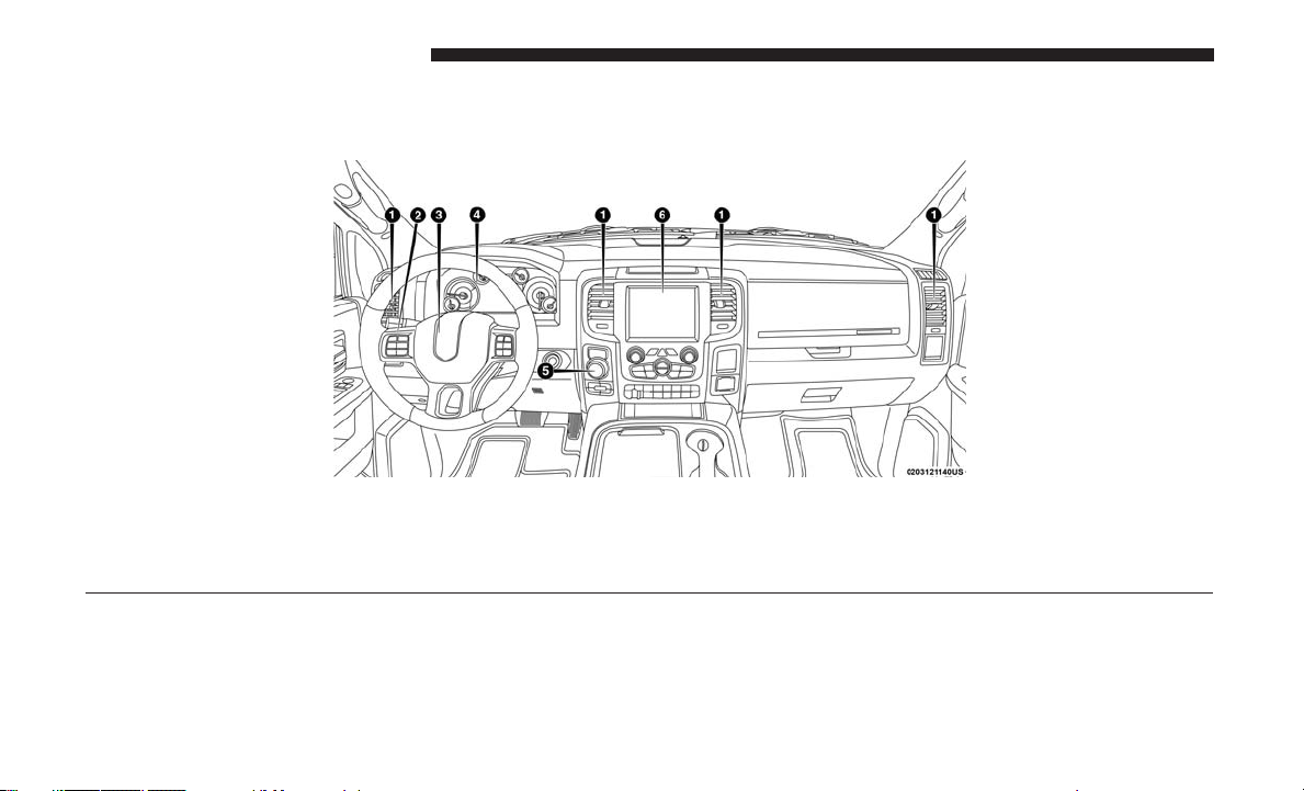
INSTRUMENT PANEL
Instrument Panel
1 — Air Vents 4 — Instrument Cluster
2 — Instrument Cluster Display Controls 5 — Gear Selector
3 — Steering Wheel 6 — Radio
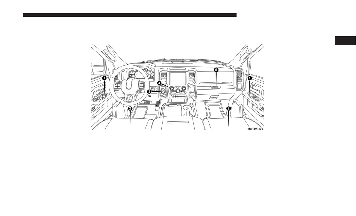
INTERIOR
Interior
1 — Door Locks/Window Switches 4 — Radio Controls
2 — Seats 5 — Storage Compartment
3 — Gear Selector
GRAPHICAL TABLE OF CONTENTS 11
2


GETTING TO KNOW YOUR VEHICLE
CONTENTS
䡵 KEYS .................................18
▫ Key Fobs .............................18
䡵 IGNITION SWITCH .......................26
▫ Wireless Ignition Node (WIN) — If Equipped....26
▫ Keyless Push Button Ignition — If Equipped ....27
▫ Key-In-Ignition Reminder .................28
䡵 REMOTE START — IF EQUIPPED .............28
▫ How To Use Remote Start..................28
▫ Remote Start Abort Message ...............28
▫ To Enter Remote Start Mode ................29
▫ To Exit Remote Start Mode Without Driving The
Vehicle ...............................29
▫ To Exit Remote Start Mode And Drive The
Vehicle ...............................29
▫ Remote Start Comfort Systems — If Equipped . . .30
▫ General Information .....................30
3
䡵 SENTRY KEY ...........................30
▫ Customer Key Programming ...............31
▫ Replacement Keys .......................31
▫ General Information .....................32
䡵 VEHICLE SECURITY ALARM ...............32
▫ To Arm The System ......................32
▫ To Disarm The System ....................33
▫ Rearming Of The System ..................34
▫ Security System Manual Override ............34
䡵 DOORS ...............................34
▫ Manual Door Locks ......................34
▫ Power Door Locks — If Equipped ...........36
▫ Keyless Enter-N-Go — Passive Entry .........36

14 GETTING TO KNOW YOUR VEHICLE
▫ Automatic Door Locks — If Equipped ........40
▫ Rear Head Restraint Removal ...............59
▫ Child-Protection Door Lock ................40
䡵 SEATS ................................41
▫ Manual Front Seat Adjustment ..............42
▫ Manual Rear Seat Adjustment ...............44
▫ Power Driver Seat Adjustment — If Equipped . . .45
▫ Power Passenger Seat Adjustment —
If Equipped ...........................47
▫ Driver Memory Seat — If Equipped ..........47
▫ Heated Seats — If Equipped ...............51
▫ Ventilated Seats — If Equipped ..............53
▫ Manual Folding Rear Seats (Mega Cab Models) . .54
▫ Plastic Grocery Bag Retainers
(Regular Cab Models) ....................57
䡵 HEAD RESTRAINTS ......................57
▫ Front Head Restraint Adjustment ............58
▫ Rear Head Restraint Adjustment .............58
▫ Front Head Restraint Removal ..............59
䡵 STEERING WHEEL .......................60
▫ Tilt Steering Column .....................60
▫ Heated Steering Wheel — If Equipped.........61
䡵 DRIVER ADJUSTABLE PEDALS — IF EQUIPPED .61
䡵 MIRRORS ..............................63
▫ Inside Day/Night Mirror — If Equipped ......63
▫ Automatic Dimming Mirror — If Equipped .....63
▫ Automatic Dimming Mirror With Rear View
Camera Display — If Equipped .............64
▫ Outside Mirrors ........................65
▫ Driver’s Outside Automatic Dimming Mirror —
If Equipped............................65
▫ Power Mirrors — If Equipped ..............66
▫ Power Folding Outside Mirrors For Standard And
Trailer Tow — If Equipped .................67
▫ Trailer Towing Mirrors — If Equipped ........69
▫ Heated Mirrors — If Equipped .............70

▫ Tilt Side Mirrors In Reverse — If Equipped .....70
GETTING TO KNOW YOUR VEHICLE 15
▫ Turn Signals ...........................77
▫ Illuminated Vanity Mirror — If Equipped ......71
䡵 EXTERIOR LIGHTS .......................72
▫ Headlight Switch .......................72
▫ Headlights ............................73
▫ Daytime Running Lights (DRL) — If Equipped . .73
▫ Multifunction Lever .....................73
▫ High/Low Beam Switch ..................74
▫ Automatic High Beam Headlamp Control — If
Equipped .............................74
▫ Flash-To-Pass ..........................75
▫ Automatic Headlights — If Equipped .........75
▫ Parking Lights And Panel Lights .............76
▫ Headlights On With Wipers (Available With
Automatic Headlights Only) ................76
▫ Headlight Delay ........................76
▫ Lights-On Reminder......................76
▫ Fog Lights — If Equipped .................77
▫ Lane Change Assist — If Equipped ..........78
▫ Cargo Light With Bed Lights — If Equipped ....78
▫ Battery Saver ...........................79
䡵 INTERIOR LIGHTS .......................79
▫ Courtesy Lights .........................79
▫ Illuminated Approach ....................82
䡵 WINDSHIELD WIPERS AND WASHERS ........83
▫ Windshield Wipers ......................83
▫ Rain Sensing Wipers — If Equipped ..........84
䡵 CLIMATE CONTROLS .....................85
▫ Manual Climate Controls Without Touchscreen . .85
▫ Manual Climate Controls With A Touchscreen . . .90
▫ Automatic Climate Controls With A Touchscreen .94
▫ Climate Control Functions.................100
▫ Automatic Temperature Control (ATC) — If
Equipped ............................101
3

16 GETTING TO KNOW YOUR VEHICLE
▫ Operating Tips ........................102
▫ Opening .............................111
䡵 WINDOWS ............................104
▫ Power Windows — If Equipped ............104
▫ Wind Buffeting ........................107
䡵 POWER SUNROOF — IF EQUIPPED .........108
▫ Opening Sunroof .......................108
▫ Closing Sunroof ........................109
▫ Wind Buffeting ........................109
▫ Sunshade Operation .....................109
▫ Pinch Protect Feature ....................109
▫ Venting Sunroof — Express ................110
▫ Sunroof Maintenance ....................110
▫ Ignition Off Operation ...................110
䡵 HOOD ...............................110
▫ To Open The Hood .....................110
▫ To Close The Hood ......................111
䡵 TAILGATE .............................111
▫ Closing ..............................111
䡵 GARAGE DOOR OPENER — IF EQUIPPED ....112
▫ Before You Begin Programming HomeLink .....113
▫ Programming A Rolling Code ..............113
▫ Programming A Non-Rolling Code...........115
▫ Canadian/Gate Operator Programming .......116
▫ Using HomeLink .......................117
▫ Security ..............................117
▫ Troubleshooting Tips ....................118
▫ General Information .....................118
䡵 INTERNAL EQUIPMENT ..................119
▫ Storage ..............................119
▫ Cupholders ..........................130
▫ Electrical
Power Outlets ..................131
▫ Cigar Lighter And Ash Receiver — If Equipped .135
▫ Power Inverter — If Equipped .............135

▫ Auxiliary Switches — If Equipped ..........136
GETTING TO KNOW YOUR VEHICLE 17
▫ Camper Applications ....................150
䡵 PICKUP BOX ...........................137
▫ Cargo Camera — If Equipped .............138
䡵 RAMBOX — IF EQUIPPED .................139
▫ RamBox Integrated Box Side Storage Bins......139
▫ Locking And Unlocking RamBox ............141
▫ RamBox Safety Warning ..................141
▫ Bed Extender — If Equipped ...............143
▫ Bed Rail Tie-Down System ................148
䡵 SLIDE-IN CAMPERS .....................150
䡵 EASY-OFF TAILGATE ....................150
▫ Disconnecting The Rear Camera Or Remote Keyless
Entry — If Equipped ....................151
▫ Removing The Tailgate ...................152
▫ Locking Tailgate........................152
䡵 TRI-FOLD TONNEAU COVER — IF EQUIPPED .153
▫ Tri-Fold Tonneau Cover Removal ...........153
▫ Tri-Fold Tonneau Cover Installation ..........158
▫ Tri-Fold Tonneau Cover Cleaning ...........164
3

18 GETTING TO KNOW YOUR VEHICLE
KEYS
Key Fobs
Your vehicle uses either a wireless ignition node system or
keyless ignition system. The ignition system consists of a
key fob with a Remote Keyless Entry (RKE) and an ignition
switch. The keyless ignition system consists of a key fob
and Keyless Enter-N-Go button.
NOTE: The key fob may not be found if it is located next to
a mobile phone, laptop or other electronic device; these
devices may block the key fob’s wireless signal.
The key fob operates the ignition switch. Insert the square
end of the key fob into the ignition switch located on the
instrument panel and rotate to the desired position. It also
contains the key fob and an emergency key, which stores in
the rear of the key fob.
The emergency key allows for entry into the vehicle should
the battery in the vehicle or the key fob go dead. You can
keep the emergency key with you when valet parking.
To remove the emergency key, slide the mechanical latch at
the top of the key fob sideways with your thumb and then
pull the key out with your other hand.
NOTE: When using the emergency key to gain access to
your vehicle, be aware that the security alarm may be
triggered. Insert the key into the ignition and place the
ignition in the ON/RUN mode to disarm the security
system.
Key Fob Emergency Key
This Keyless Push Button Ignition key fob allows the driver
to operate the ignition switch with the push of a button, as
long as the key fob is in the passenger compartment. The
Keyless Push Button Ignition has four operating positions,
three of which are labeled and will illuminate when in
position. The three positions are OFF, ACC, and ON/RUN.

The fourth position is START, during start RUN will
illuminate. It also contains the key fob and an emergency
key, which stores in the rear of the key fob.
The emergency key allows for entry into the vehicle should
the battery in the vehicle or the key fob go dead. You can
keep the emergency key with you when valet parking.
To remove the emergency key, slide the mechanical latch
on the backside of the key fob sideways with your thumb
and then pull the key out with your other hand.
NOTE: When using the emergency key to gain access to
your vehicle, be aware that the security alarm may be
triggered. Put the nose side (side opposite of the emergency key) of the key fob against the ENGINE START/
STOP button and push to disarm the security system.
GETTING TO KNOW YOUR VEHICLE 19
3
Key Fob Emergency Key
NOTE: You can insert the double-sided emergency key
into the door lock cylinder with either side up.
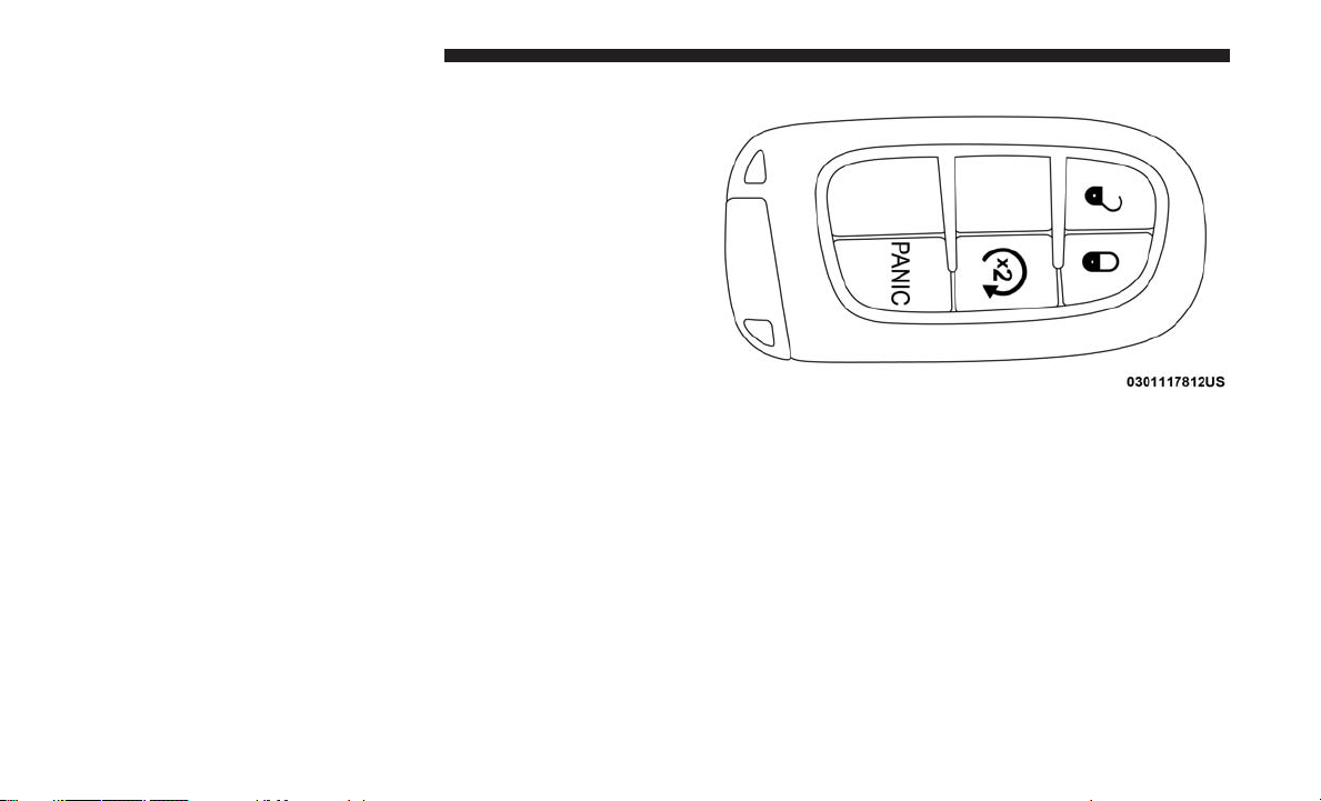
The Remote Keyless Entry system allows you to lock or
unlock all doors, tailgate, and the RamBox (if equipped) as
well as activate the Panic Alarm from distances up to
approximately 66 ft (20 m) using a key fob with integrated
key. The key fob does not need to be pointed at the vehicle
to activate the system. Push and release the lock button on
the key fob to lock all doors, the tailgate and the RamBox
(if equipped). The turn signal lights will flash and the horn
will chirp to acknowledge the signal.
20 GETTING TO KNOW YOUR VEHICLE
NOTE: Inserting the key fob with integrated key into the
ignition switch disables the system from responding to any
button pushes from that key fob. Driving at speeds 5 mph
(8 km/h) and above disables the system from responding
to all key fob buttons for all key fobs.
WIN Key Fob With Integrated Key
Passive Entry Key Fob
To Unlock The Doors And Tailgate
Push and release the unlock button on the key fob once to
unlock the driver’s door. Push the unlock button twice
within five seconds to unlock all doors, the tailgate and the
RamBox (if equipped). The turn signal lights will flash to
acknowledge the unlock signal. The illuminated entry
system will also turn on.
NOTE: The instrument cluster display or Uconnect Settings are setup for driver door first, otherwise this will
unlock all doors.

To Lock The Doors And Tailgate
Push and release the lock button on the key fob to lock all
doors, the tailgate, and the RamBox (if equipped). The turn
signal lights will flash and the horn will chirp to acknowledge the signal.
GETTING TO KNOW YOUR VEHICLE 21
Using The Panic Alarm
To turn the Panic Alarm feature on or off, push the Panic
button on the key fob. When the Panic Alarm is activated,
the turn signals will flash, the horn will pulse on and off,
and the interior lights will turn on.
3
Sound Horn With Lock
This feature will cause the horn to chirp when the doors are
locked with the key fob. This feature can be turned on or
turned off. To change the current setting, proceed as
follows:
• For vehicles not equipped with a touchscreen radio,
refer to “Instrument Cluster Display” in “Getting To
Know Your Instrument Panel” for further information.
• For vehicles equipped with a touchscreen radio, refer to
“Uconnect Settings” in “Multimedia” for further information.
NOTE: Pushing the lock button on the key fob while you
are in the vehicle will activate the vehicle security alarm
system. Opening a door with the vehicle security alarm
system activated will cause the alarm to sound. Push the
unlock button to deactivate the vehicle security alarm
system.
The Panic Alarm will stay on for three minutes unless you
turn it off by either pushing the Panic button a second time
or drive the vehicle at a speed of 15 mph (24 km/h) or
greater.
NOTE:
• The interior lights will turn off if you place the ignition
in the ACC or ON/RUN position while the Panic Alarm
is activated. However, the exterior lights and horn will
remain on.
• You may need to be less than 35 ft (11 m) from the
vehicle when using the key fob to turn off the Panic
Alarm due to the radio frequency noises emitted by the
system.

22 GETTING TO KNOW YOUR VEHICLE
Air Suspension (Remote Lowering Of The Vehicle) — If Equipped
For easy entry and loading, your vehicle can be
lowered by pushing the key fob air suspension
lowering button two times. When key fob low-
ering is requested, the vehicle will send a series
of chirps and flashes to alert the customer that the operation has begun and will continue these alerts until it
successfully lowers.
The following conditions must be met for the vehicle to
lower remotely:
• The vehicle must not already be in Entry/Exit (Park)
ride height.
• The vehicle battery must be fully charged.
• All doors must be closed.
• The key fob must be out of the vehicle.
Canceling Remote Lowering
Vehicle lowering can be cancelled at anytime. When vehicle
lowering is canceled, the vehicle will raise up to the next
defined level and lock out the remote lowering feature
until the ignition has been cycled ON/OFF.
To cancel vehicle lowering, push the key fob air suspension
lowering button one time during the lowering process.
When vehicle lowering is canceled, the horn will chirp two
times and the turn signal lamps will flash four times. Once
raising is completed, the horn will chirp one time.
NOTE: Refer to “Air Suspension System” in “Starting And
Operating” for further information.
Replacing The Battery In The Key Fob With Remote Control
The replacement battery is one CR2032 battery.
NOTE:
• Perchlorate Material — special handling may apply. See
www.dtsc.ca.gov/hazardouswaste/perchlorate for further information.

• Do not touch the battery terminals that are on the back
housing or the printed circuit board.
1. Remove the emergency key by sliding the mechanical
latch on the back of the key fob sideways with your
thumb and then pull the key out with your other hand.
Emergency Key Removal
GETTING TO KNOW YOUR VEHICLE 23
3
Emergency Key Removal
24 GETTING TO KNOW YOUR VEHICLE
2. Separating key fob halves requires screw removal – if
equipped, and gently prying the two halves of the key
fob apart. Make sure not to damage the seal during
removal.
Remove Screw From Key Fob Case
Separating Key Fob Case

GETTING TO KNOW YOUR VEHICLE 25
Programming Additional Key Fobs
Programming the key fob may be performed by an authorized dealer.
Separating Key Fob Case
3. Remove the battery by turning the back cover over
(battery facing downward) and tapping it lightly on a
solid surface such as a table or similar, then replace the
battery. When replacing the battery, match the + sign on
the battery to the + sign on the inside of the battery clip,
located on the back cover. Avoid touching the new
battery with your fingers. Skin oils may cause battery
deterioration. If you touch a battery, clean it with
rubbing alcohol.
4. To assemble the key fob case, snap the two halves
together, reposition and secure the screw as shown in
step #2 for removal.
NOTE: Once a key fob is programmed to a vehicle, it
cannot be repurposed and reprogrammed to another vehicle.
General Information
The following regulatory statement applies to all radio
frequency (RF) devices equipped in this vehicle:
This device complies with Part 15 of the FCC Rules and
with Industry Canada license-exempt RSS standard(s).
Operation is subject to the following two conditions:
1. This device may not cause harmful interference, and
2. This device must accept any interference received, including interference that may cause undesired operation.
NOTE: Changes or modifications not expressly approved
by the party responsible for compliance could void the
user’s authority to operate the equipment.
3

26 GETTING TO KNOW YOUR VEHICLE
IGNITION SWITCH
Wireless Ignition Node (WIN) — If Equipped
The Wireless Ignition Node (WIN) operates similar to an
ignition switch. It has four operating positions, three with
detents and one that is spring-loaded. The detent positions
are OFF, ACC, and ON/RUN. The START position is a
spring-loaded momentary contact position. When released
from the START position, the switch automatically returns
to the ON/RUN position.
Wireless Ignition Switch
1—OFF
2 — ACC (Accessory)
3 — ON/RUN
4 — START

Keyless Push Button Ignition — If Equipped
This feature allows the driver to operate the ignition switch
with the push of a button as long as the Remote Keyless
Entry key fob is in the passenger compartment.
The Keyless Push Button Ignition has four operating
positions; three of which are labeled and will illuminate
when in position. The three positions are OFF, ACC, and
ON/RUN. The fourth position is START, during start RUN
will illuminate.
NOTE: In case the ignition switch does not change with
the push of a button, the key fob may have a low or dead
battery. In this situation, a back up method can be used to
operate the ignition switch. Put the nose side (side opposite
of the emergency key) of the key fob against the ENGINE
START/STOP button, with your foot applied on the brake
pedal, and push to operate the ignition switch.
GETTING TO KNOW YOUR VEHICLE 27
3
Keyless Push Button Ignition
1—OFF
2 — ACC (Accessory)
3 — ON/RUN

28 GETTING TO KNOW YOUR VEHICLE
Key-In-Ignition Reminder
Opening the driver’s door when the key fob is in the
ignition and the ignition switch position is OFF or ACC, a
chime will sound to remind you to remove the key fob.
NOTE:
• ⬙Keyed⬙ Ignition systems will chime in OFF or ACC
when the driver door is open.
• “Keyless⬙ Ignition systems will chime in ACC or RUN
when the driver door is open.
• The instrument cluster display will display “Key In
Ignition.”
REMOTE START — IF EQUIPPED
How To Use Remote Start
All of the following conditions must be met before the
engine will remote start:
• Gear selector in PARK
• Doors closed
• Hood closed
• HAZARD switch off
• BRAKE switch inactive (brake pedal not pushed)
• Ignition key removed from ignition switch
• Battery at an acceptable charge level
• PANIC button not pushed
• Fuel meets minimum requirement
• System not disabled from previous remote start event
• Vehicle security alarm not active
WARNING!
• Do not start or run an engine in a closed garage or
confined area. Exhaust gas contains Carbon Monoxide (CO) which is odorless and colorless. Carbon
Monoxide is poisonous and can cause serious injury
or death when inhaled.
• Keep key fobs away from children. Operation of the
Remote Start System, windows, door locks or other
controls could cause serious injury or death.
Remote Start Abort Message
The following messages will display in the instrument
cluster display if the vehicle fails to remote start or exits
remote start prematurely:
• Remote Start Cancelled — Door Open

• Remote Start Cancelled — Hood Open
• Remote Start Cancelled — Fuel Low
• Remote Start Cancelled — System Fault
• Remote Start Disabled — Start Vehicle to Reset
The instrument cluster display message stays active until
the ignition is turned to the ON/RUN position.
To Enter Remote Start Mode
Push and release the Remote Start button on the key fob
twice within five seconds. The parking lights will flash,
vehicle doors will lock, and the horn will chirp twice (if
programmed). Once the vehicle has started, the engine will
run for 15 minutes.
NOTE:
• If your power door locks were unlocked, Remote Start
will automatically lock the doors.
• If an engine fault is present or fuel level is low, the
vehicle will start and then shut down in 10 seconds.
• The park lamps will turn on and remain on during
Remote Start mode.
GETTING TO KNOW YOUR VEHICLE 29
• For security, power window and power sunroof operation (if equipped) are disabled when the vehicle is in the
Remote Start mode.
• The engine can be started two consecutive times (two
15-minute cycles) with the key fob. However, the ignition must be placed in the ON/RUN position before you
can repeat the start sequence for a third cycle.
To Exit Remote Start Mode Without Driving The Vehicle
Push and release the remote start button one time or allow
the engine to run for the entire 15-minute cycle.
NOTE: To avoid unintentional shutdowns, the system will
disable with a one time push of the remote start button for
two seconds after receiving a valid remote start request.
To Exit Remote Start Mode And Drive The Vehicle
Before the end of the 15-minute cycle, push and release the
unlock button on the key fob to unlock the doors and
disarm the vehicle security alarm system (if equipped).
Then, prior to the end of the 15-minute cycle, cycle the
ignition to the ON/RUN position.
3

30 GETTING TO KNOW YOUR VEHICLE
Remote Start Comfort Systems — If Equipped
When Remote Start is activated, the heated steering wheel
and driver heated seat features will automatically turn on
in cold weather. In warm weather, the driver vented seat
feature will automatically turn on when the remote start is
activated. These features will stay on through the duration
of Remote Start or until the ignition switch is placed in the
ON/RUN mode.
NOTE: The Remote Start Comfort System can be activated
and deactivated through the Uconnect System. Refer to
“Uconnect Settings” in “Multimedia” for further information on Remote Start Comfort System operation.
General Information
The following regulatory statement applies to all radio
frequency (RF) devices equipped in this vehicle:
This device complies with Part 15 of the FCC Rules and
with Industry Canada license-exempt RSS standard(s).
Operation is subject to the following two conditions:
1. This device may not cause harmful interference, and
2. This device must accept any interference received, including interference that may cause undesired operation.
NOTE: Changes or modifications not expressly approved
by the party responsible for compliance could void the
user’s authority to operate the equipment.
SENTRY KEY
The Sentry Key Immobilizer System prevents unauthorized vehicle operation by disabling the engine. The system
does not need to be armed or activated. Operation is
automatic, regardless of whether the vehicle is locked or
unlocked.
The system uses a key fob, an Ignition Node Module,
Keyless Push Button Ignition and a RF receiver to prevent
unauthorized vehicle operation. Therefore, only key fobs
that are programmed to the vehicle can be used to start and
operate the vehicle. The system will not allow the engine to
crank if an invalid key fob is used to start and operate the
vehicle. The system will shut the engine off in two seconds
if an invalid key fob is used to start the engine.
NOTE: A key fob that has not been programmed is also
considered an invalid key.
During normal operation, after placing the keyless ignition
in the ON/RUN position, the vehicle security light will
turn on for three seconds for a bulb check. If the light
remains on after the bulb check, it indicates that there is a

problem with the electronics. In addition, if the light begins
to flash after the bulb check, it indicates that someone used
an invalid key fob to try to start the engine. Either of these
conditions will result in the engine being shut off after two
seconds.
If the vehicle security light turns on during normal vehicle
operation (vehicle running for longer than 10 seconds), it
indicates that there is a fault in the electronics. Should this
occur, have the vehicle serviced as soon as possible by an
authorized dealer.
CAUTION!
The Sentry Key Immobilizer system is not compatible
with some aftermarket remote starting systems. Use of
these systems may result in vehicle starting problems
and loss of security protection.
All of the key fobs provided with your new vehicle have
been programmed to the vehicle electronics.
Customer Key Programming
Programming key fobs may be performed at an authorized
dealer.
GETTING TO KNOW YOUR VEHICLE 31
Replacement Keys
NOTE: Only key fobs that are programmed to the vehicle
electronics can be used to start and operate the vehicle.
Once a key fob is programmed to a vehicle, it cannot be
programmed to any other vehicle.
CAUTION!
• Always remove the key fobs from the vehicle and
lock all doors when leaving the vehicle unattended.
• For vehicles equipped with Keyless Enter-N-Go —
Ignition, always remember to place the ignition in
the OFF position.
NOTE: Duplication of key fobs may be performed at an
authorized dealer. This procedure consists of programming
a blank key fob to the vehicle electronics. A blank key fob
is one that has never been programmed.
When having the Sentry Key Immobilizer System serviced,
bring all vehicle keys with you to an authorized dealer.
3

32 GETTING TO KNOW YOUR VEHICLE
General Information
The following regulatory statement applies to all radio
frequency (RF) devices equipped in this vehicle:
This device complies with Part 15 of the FCC Rules and
with Industry Canada license-exempt RSS standard(s).
Operation is subject to the following two conditions:
1. This device may not cause harmful interference, and
2. This device must accept any interference received, including interference that may cause undesired operation.
NOTE: Changes or modifications not expressly approved
by the party responsible for compliance could void the
user’s authority to operate the equipment.
VEHICLE SECURITY ALARM
The vehicle security alarm monitors the vehicle doors and
ignition for unauthorized operation. When the vehicle
security alarm is activated, interior switches for door locks
are disabled. The system provides both audible and visible
signals for the first three minutes. The horn will sound, the
headlights will turn on, the park lamps and/or turn signals
will flash and vehicle security light will flash repeatedly.
For an additional 15 minutes only, the headlights will turn
on, the park lamps and/or turn signals, and vehicle
security light will flash.
To Arm The System
Follow these steps to arm the vehicle security alarm:
1. Remove the key from the ignition system (refer to
⬙Starting The Engine⬙ in ⬙Starting And Operating⬙ for
further information).
• For vehicles equipped with Keyless Enter-N-Go —
Ignition, make sure the vehicle ignition system is
⬙OFF.⬙
• For vehicles not equipped with Keyless Enter-N-Go —
Ignition, make sure the vehicle ignition system is
⬙OFF⬙ and the key is physically removed from the
ignition.
2. Perform one of the following methods to lock the
vehicle:
• Push lock button on the interior power door lock
switch with the driver and/or passenger door open.
• Push the lock button on the exterior Passive Entry
Door Handle with a valid key fob available in the same

exterior zone (refer to ⬙Keyless Enter- N-Go — Passive
Entry⬙ in ⬙Getting To Know Your Vehicle⬙ for further
information).
• Push the lock button on the key fob.
3. If any doors are open, close them.
The vehicle security alarm will set when you use the power
door locks, or use the key fob to lock the doors. After all the
doors are locked and closed, the vehicle security light, in
the instrument panel cluster, will flash rapidly for about 16
seconds to indicate that the alarm is being set. After the
alarm is set, the vehicle security light will flash at a slower
rate to indicate that the system is armed.
To Disarm The System
The vehicle security alarm can be disarmed using any of
the following methods:
1. Push the unlock button on the key fob.
2. Grasp the Passive Entry Unlock Door Handle with a
valid key fob within 5 ft (1.5 m) of the passive entry door
handle. If equipped, refer to ⬙Keyless Enter-N-Go —
Passive Entry⬙ in ⬙Getting To Know Your Vehicle⬙ for
further information.
GETTING TO KNOW YOUR VEHICLE 33
3. Cycle the ignition out of the OFF position.
• For vehicles equipped with Keyless Enter-N-Go —
Ignition, push the Keyless Ignition START/STOP button (requires at least one valid key fob in the vehicle).
• For vehicles not equipped with Keyless Enter-N-Go,
insert a valid key into the ignition switch and turn the
key to the ON position.
The vehicle security alarm is designed to protect your
vehicle. However, you can create conditions where the
system will give you a false alarm. If one of the previously
described arming sequences has occurred, the vehicle
security alarm will arm regardless of whether you are in
the vehicle or not. If you remain in the vehicle and open a
door, the alarm will sound. If this occurs, disarm the
vehicle security alarm.
If the vehicle security alarm is armed and the battery
becomes disconnected, the vehicle security alarm will
remain armed when the battery is reconnected; the exterior
lights will flash, and the horn will sound. If this occurs,
disarm the vehicle security alarm.
3

34 GETTING TO KNOW YOUR VEHICLE
Rearming Of The System
The vehicle security alarm will rearm itself after the 15
additional minutes of headlights and vehicle security light
flashing, if the system has not been disabled. If the condition which initiated the alarm is still present, the system
will ignore that condition and monitor the remaining doors
and ignition.
Security System Manual Override
The vehicle security alarm will not arm if you lock the
doors using the manual door lock plunger.
DOORS
Manual Door Locks
Front and rear doors may be locked by moving the lock
knob down or unlocked by moving the lock knob up.
Door Lock Knob
Front doors may be opened with the inside door handle
without lifting the lock knob.
Doors locked before closing will remain locked when
closed.
The emergency key will unlock the driver door lock on
your vehicle.

GETTING TO KNOW YOUR VEHICLE 35
WARNING!
• Do not leave children or animals inside parked
vehicles in hot weather. Interior heat build-up may
cause serious injury or death.
• For personal security and safety in the event of an
collision, lock the vehicle doors as you drive as well
as when you park and leave the vehicle.
• Before exiting a vehicle, always shift the automatic
transmission into PARK or the manual transmission
into FIRST gear or REVERSE, apply the parking
brake, turn the vehicle OFF, remove the key fobs
from vehicle, and lock all doors. and lock your
vehicle.
• Never leave children alone in a vehicle, or with
access to an unlocked vehicle. Leaving children in a
vehicle unattended is dangerous for a number of
reasons. A child or others could be seriously or
fatally injured. Children should be warned not to
touch the parking brake, brake pedal or the gear
selector.
(Continued)
WARNING! (Continued)
• Allowing children to be in a vehicle unattended is
dangerous for a number of reasons. A child or others
could be seriously or fatally injured. Children
should be warned not to touch the parking brake,
brake pedal or the gear selector.
• Do not leave the key fob in or near the vehicle, or in
a location accessible to children, and do not leave the
ignition of a vehicle equipped with Keyless EnterN-Go in the ACC or ON/RUN mode. A child could
operate power windows, other controls, or move the
vehicle.
3

36 GETTING TO KNOW YOUR VEHICLE
Power Door Locks — If Equipped
The power door lock switches are on each front door trim
panel. Use these switches to lock or unlock the doors.
NOTE: The key fob may not be able to be detected by the
vehicle Keyless Enter-N-Go system if it is located next to a
mobile phone, laptop or other electronic device; these
devices may block the key fob’s wireless signal and prevent
the Keyless Enter-N-Go system from starting the vehicle.
Power Door Lock Switch
If you push the power door lock switch while the key fob
is in the ignition, and any front door is open, the power
locks will not operate. This prevents you from accidentally
locking your key fob in the vehicle. Removing the key fob
or closing the door will allow the locks to operate. A chime
will sound if the key fob is in the ignition switch and a door
is open, as a reminder to remove the key fob.
Keyless Enter-N-Go — Passive Entry
The Passive Entry system is an enhancement to the vehicle’s Remote Keyless Entry system and a feature of Keyless
Enter-N-Go. This feature allows you to lock and unlock the
vehicle’s door(s) without having to push the key fob lock
or unlock buttons.
NOTE:
• Passive Entry may be programmed ON/OFF. Refer to
“Uconnect Settings” in “Multimedia” for further information.
• If wearing gloves on your hands, or if it has been
raining/snowing on the Passive Entry door handle, the
unlock sensitivity can be affected, resulting in a slower
response time.
• If the vehicle is unlocked by Passive Entry and no door
is opened within 60 seconds, the vehicle will re-lock and
if equipped will arm the security alarm.

• The vehicles security alarm can be armed/disarmed by
pushing the passive entry key fob lock/unlock buttons
(if equipped).
• The key fob may not be able to be detected by the vehicle
passive entry system if it is located next to a mobile
phone, laptop or other electronic device; these devices
may block the key fob’s wireless signal and prevent the
passive entry handle from locking/unlocking the vehicle.
To Unlock From The Driver’s Side:
With a valid Passive Entry key fob within 5 ft (1.5 m) of the
driver door handle, grab the front driver door handle to
unlock the driver’s door automatically. The interior door
panel lock knob will raise when the door is unlocked.
GETTING TO KNOW YOUR VEHICLE 37
3
Grab The Door Handle To Unlock
NOTE: If “Unlock All Doors 1st Press” is programmed, all
doors will unlock when you grab hold of the front driver’s
door handle. To select between “Unlock Driver Door 1st
Press” and “Unlock All Doors 1st Press,” refer to
“Uconnect Settings” in “Multimedia” for further information.

38 GETTING TO KNOW YOUR VEHICLE
To Unlock From The Passenger Side:
With a valid Passive Entry key fob within 5 ft (1.5 m) of the
passenger door handle, grab the front passenger door
handle to unlock all doors automatically. The interior door
panel lock knob will raise when the door is unlocked.
NOTE: All doors will unlock when the front passenger
door handle is grabbed regardless of the driver’s door
unlock preference setting (“Unlock Driver Door 1st Press”
or “Unlock All Doors 1st Press”).
Preventing Inadvertent Locking Of Passive Entry Key
Fob In Vehicle:
To minimize the possibility of unintentionally locking a
Passive Entry key fob inside your vehicle, the Passive Entry
system is equipped with an automatic door unlock feature
which will function if the ignition switch is in the OFF
position.
If one of the vehicle doors is open and the door panel
switch is used to lock the vehicle, once all open doors have
been closed the vehicle checks the inside and outside of the
vehicle for any valid Passive Entry key fobs. If one of the
vehicle’s Passive Entry key fobs is detected inside the
vehicle, and no other valid Passive Entry key fobs are
detected outside the vehicle, the Passive Entry System
automatically unlocks all vehicle doors and chirps the horn
three times (on the third attempt ALL doors will lock and
the Passive Entry key fob can be locked in the vehicle).
To Lock The Vehicle’s Doors:
With one of the vehicle’s Passive Entry key fobs within 5 ft
(1.5 m) of the driver or passenger front door handles, push
the door handle lock button to lock all doors.
Push The Door Handle Button To Lock

Do NOT grab the door handle when pushing the door
handle lock button. This could unlock the door(s).
GETTING TO KNOW YOUR VEHICLE 39
The vehicle doors can also be locked by using the key fob
lock button or the lock button located on the vehicle’s
interior door panel.
Do NOT Grab The Door Handle When Locking
NOTE:
• After pushing the door handle lock button, you must
wait two seconds before you can lock or unlock the
doors, using either Passive Entry door handle. This is
done to allow you to check if the vehicle is locked by
pulling the door handle, without the vehicle reacting
and unlocking.
• The Passive Entry system will not operate if the key fob
battery is dead.
General Information
The following regulatory statement applies to all radio
frequency (RF) devices equipped in this vehicle:
This device complies with Part 15 of the FCC Rules and
with Industry Canada license-exempt RSS standard(s).
Operation is subject to the following two conditions:
1. This device may not cause harmful interference, and
2. This device must accept any interference received, including interference that may cause undesired operation.
NOTE: Changes or modifications not expressly approved
by the party responsible for compliance could void the
user’s authority to operate the equipment.
3

40 GETTING TO KNOW YOUR VEHICLE
Automatic Door Locks — If Equipped
The auto door lock feature default condition is enabled.
When enabled, the door locks will lock automatically when
the vehicle’s speed exceeds 15 mph (24 km/h). The auto
door lock feature can be enabled or disabled by an authorized dealer per written request of the customer. Please see
an authorized dealer for service.
Automatic Doors Unlock — If Equipped
This feature unlocks all of the doors of the vehicle when
either front door is opened. This will occur only after the
vehicle has been shifted into the PARK position after the
vehicle has been driven (shifted out of PARK and all doors
closed).
Automatic Doors Unlock Programming — If Equipped
The Automatic Doors Unlock feature can be enabled or
disabled as follows:
• For vehicles not equipped with a touchscreen radio,
refer to “Instrument Cluster Display” in “Getting To
Know Your Instrument Panel” for further information.
For vehicles equipped with a touchscreen radio, refer to
•
“Uconnect Settings” in “Multimedia” for further information.
NOTE: Use the Auto Unlock Doors feature in accordance
with local laws.
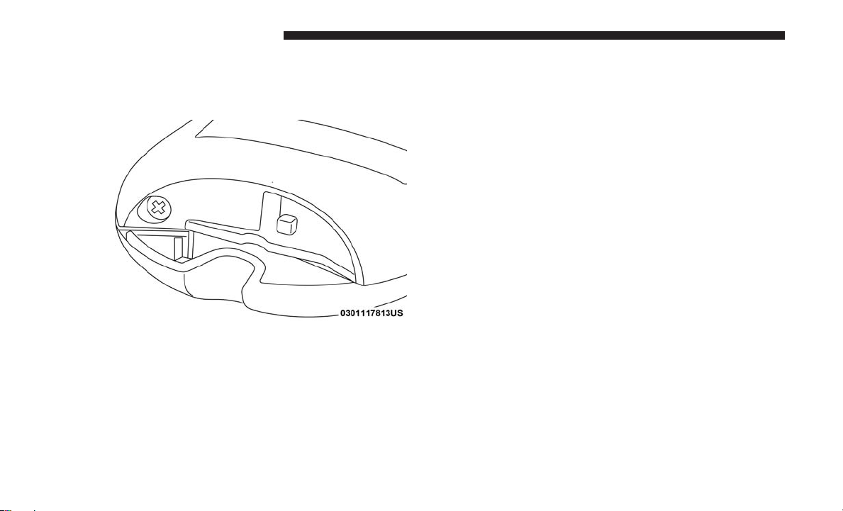
Child-Protection Door Lock
To provide a safer environment for children riding in the
rear seat, the rear doors (if equipped) of your vehicle have
the Child-Protection Door Lock system.
Child-Protection Door Lock Location

To use the system, open each rear door, use a flat blade
screwdriver (or emergency key) and rotate the dial to
engage and disengage the Child-Protection locks. When
the system on a door is engaged, that door can only be
opened by using the outside door handle even if the inside
door lock is in the unlocked position.
GETTING TO KNOW YOUR VEHICLE 41
WARNING! (Continued)
the outside with the Child-Protection locks are engaged (locked).
NOTE:
• After setting the Child-Protection Door Lock system,
always test the door from the inside to make certain it is
in the desired position.
• For emergency exit with the system engaged, move the
door lock switch to the unlock position, roll down the
window and open the door with the outside door
handle.
SEATS
Seats are a part of the Occupant Restraint System of the
vehicle.
3
Child Lock Control
WARNING!
Avoid trapping anyone in a vehicle in a collision.
Remember that the rear doors can only be opened from
(Continued)
WARNING!
• It is dangerous to ride in a cargo area, inside or
outside of a vehicle. In a collision, people riding in
these areas are more likely to be seriously injured or
killed.
(Continued)

42 GETTING TO KNOW YOUR VEHICLE
WARNING! (Continued)
• Do not allow people to ride in any area of your
vehicle that is not equipped with seats and seat belts.
In a collision, people riding in these areas are more
likely to be seriously injured or killed.
• Be sure everyone in your vehicle is in a seat and
using a seat belt properly.
Manual Front Seat Adjustment
Manual Front Seat Forward/Rearward Adjustment
Both front seats are adjustable forward or rearward. The
manual seat adjustment handle is located under the seat
cushion at the front edge of each seat.
Manual Seat Adjuster
While sitting in the seat, pull up on the handle and slide the
seat forward or rearward. Release the bar once you have
reached the desired position. Then, using body pressure,
move forward and rearward on the seat to be sure that the
seat adjusters have latched.

WARNING!
• Adjusting a seat while driving may be dangerous.
Moving a seat while driving could result in loss of
control which could cause a collision and serious
injury or death.
• Seats should be adjusted before fastening the seat
belts and while the vehicle is parked. Serious injury
or death could result from a poorly adjusted seat belt.
Manual Front Seat Recline Adjustment
The recline lever is located on the outboard side of the seat.
To recline the seat, lean forward slightly, lift the lever, lean
back to the desired position and release the lever. To return
the seatback to its normal upright position, lean forward
and lift the lever. Release the lever once the seat back is in
the upright position
GETTING TO KNOW YOUR VEHICLE 43
3
Manual Recline Lever
Dump Feature (Manual Recline Seat Only) — Standard
Cab
Actuating the recliner handle will allow the seat back to
swing (dump) forward on manual recliner seats. This
“dump” feature allows access to the storage bin behind the
seat.

44 GETTING TO KNOW YOUR VEHICLE
WARNING!
• Do not stand or lean in front of the seat while
actuating the handle. The seatback may swing forward and hit you causing injury.
• To avoid injury, place your hand on the seatback and
actuate the handle, then position the seatback in the
desired position.
40-20-40 Front Bench Seat — If Equipped
The seat is divided into three segments. The outboard seat
portions are each 40% of the total width of the seat. On
some models, the back of the center portion (20%) easily
folds down to provide an armrest/center storage compartment.
Manual Rear Seat Adjustment
Reclining Rear Seats — If Equipped
The recliner handle is located on the outside of the seat
cushion. To adjust the seatback, lift upward on the handle,
lean back on the seatback and when you reach the desired
position, release the handle.
Rear Seat Recliner Handle
WARNING!
Do not ride with the seatback reclined so that the
shoulder belt is no longer resting against your chest. In
a collision you could slide under the seat belt, which
could result in serious injury or death.

Power Driver Seat Adjustment — If Equipped
Some models may be equipped with an eight-way power
driver’s seat. The power seat switches are located on the
outboard side of the driver’s seat cushion. There are two
power seat switches that are used to control the movement
of the seat cushion and the seatback.
GETTING TO KNOW YOUR VEHICLE 45
Adjusting The Seat Forward Or Rearward
The seat can be adjusted both forward and rearward. Push
the seat switch forward or rearward. The seat will move in
the direction of the switch. Release the switch when the
desired position has been reached.
Adjusting The Seat Up Or Down
The height of the seats can be adjusted up or down. Pull
upward or push downward on the rear of seat switch, the
seat will move in the direction of the switch. Release the
switch when the desired position has been reached.
Tilting The Seat Up Or Down
The angle of the seat cushion can be adjusted in four
directions. Pull upward or push downward on the front or
rear of the seat switch, the front or rear of the seat cushion
will move in the direction of the switch. Release the switch
when the desired position is reached.
3
Power Seat Switches
1 — Power Seat Switch
2 — Power Seatback Switch
Reclining The Seatback
The angle of the seatback can be adjusted forward or
rearward. Push the seatback switch forward or rearward,
the seat will move in the direction of the switch. Release the
switch when the desired position is reached.

46 GETTING TO KNOW YOUR VEHICLE
WARNING!
• Adjusting a seat while driving may be dangerous.
Moving a seat while driving could result in loss of
control which could cause a collision and serious
injury or death.
• Seats should be adjusted before fastening the seat
belts and while the vehicle is parked. Serious injury
or death could result from a poorly adjusted seat belt.
• Do not ride with the seatback reclined so that the
shoulder belt is no longer resting against your chest.
In a collision you could slide under the seat belt,
which could result in serious injury or death.
CAUTION!
Do not place any article under a power seat or impede
its ability to move as it may cause damage to the seat
controls. Seat travel may become limited if movement
is stopped by an obstruction in the seat’s path.
Power Lumbar — If Equipped
Vehicles equipped with power driver or passenger seats
may be also be equipped with power lumbar. The power
lumbar switch is located on the outboard side of the power
seat. Push the switch forward to increase the lumbar
support. Push the switch rearward to decrease the lumbar
support.
Lumbar Control Switch

Power Passenger Seat Adjustment — If Equipped
Some models are equipped with a six-way power passenger seat. The power seat switch is located on the outboard
side of the seat. The switch is used to control the movement
of the seat and seat cushion.
Adjusting The Seat Forward Or Rearward
The seat can be adjusted both forward and rearward. Push
the seat switch forward or rearward. The seat will move in
the direction of the switch. Release the switch when the
desired position has been reached.
Adjusting The Seat Up Or Down
The height of the seats can be adjusted up or down. Pull
upward or push downward on the rear of seat switch, the
seat will move in the direction of the switch. Release the
switch when the desired position has been reached.
Tilting The Seat Up Or Down
The angle of the seat cushion can be adjusted in four
directions. Pull upward or push downward on the front or
rear of the seat switch, the front or rear of the seat cushion
will move in the direction of the switch. Release the switch
when the desired position is reached.
GETTING TO KNOW YOUR VEHICLE 47
Driver Memory Seat — If Equipped
This feature allows the driver to store up to two different
memory profiles for easy recall through a memory switch.
Each memory profile contains desired position settings for
the driver’s seat, side mirrors, adjustable pedals (if
equipped) and a set of desired radio station presets. Your
remote keyless entry key fob can also be programmed to
recall the same positions when the unlock button is
pushed.
NOTE: Your vehicle is equipped with two key fobs, one
key fob can be linked to memory position 1 and the other
key fob can be linked to memory position 2.
3

48 GETTING TO KNOW YOUR VEHICLE
The memory seat buttons are located on the outboard side
of the driver’s seat cushion.
Memory Seat Buttons
Programming The Memory Feature
To create a new memory profile, perform the following:
1. Cycle the vehicle’s ignition to the ON/RUN position (do
not start the engine).
2. Adjust all memory profile settings to desired preferences (i.e., driver’s seat, outside mirrors and radio
station presets).
3. Push and release the set (S) button on the memory
switch.
4. Within five seconds, push and release either of the
memory buttons (1) or (2). The instrument cluster display will show which memory position has been set.
NOTE:
• Memory profiles can be set without the vehicle in PARK,
but the vehicle must be in PARK to recall a memory
profile.
• To set a memory profile to your key fob, refer to
“Linking And Unlinking The Remote Keyless Entry Key
Fob To Memory” in this section.

Linking And Unlinking The Remote Keyless Entry Key Fob To Memory
Your key fobs can be programmed to recall one of two
pre-programmed memory profiles by pushing the unlock
button on the key fob.
NOTE: Before programming your key fobs to memory the
feature has to be selected.
• If your vehicle is equipped with a touchscreen, you must
select the “Memory Linked To Fob” feature through the
Uconnect system. Refer to “Uconnect Settings” in “Multimedia” for further information.
• If your vehicle is not equipped with a touchscreen, you
must select the “Key Fob Linked To Memory” feature
through the instrument cluster display. Refer to “Instrument Cluster Display” in “Getting To Know Your Instrument Panel” for further information.
GETTING TO KNOW YOUR VEHICLE 49
To program your key fobs, perform the following:
1. Cycle the vehicle’s ignition to the OFF position.
2. Select desired memory profile (1) or (2).
NOTE: If a memory profile has not already been set, refer
to ⬙Programming The Memory Feature⬙ for instructions on
how to set a memory profile.
3. Once the profile has been recalled, push and release the
set (S) button on the memory switch, then push and
release button (1) or (2) accordingly. “Memory Profile
Set” (1 or 2) will display in the instrument cluster
display.
4. Push and release the lock button on the key fob within
10 seconds.
NOTE: Your key fobs can be unlinked to your memory
settings by pushing the set (S) button, and within 10
seconds, followed by pushing the unlock button on the key
fob.
3

50 GETTING TO KNOW YOUR VEHICLE
Memory Position Recall
NOTE:
• For vehicles equipped with an automatic transmission,
the vehicle speed must be lower than 5 mph (8 km/h) to
recall memory positions. If a recall is attempted when
the vehicle speed is greater than 5 mph (8 km/h), a
message will be displayed in the instrument cluster
display.
• For vehicles equipped with a manual transmission, the
vehicle speed must be at 0 mph (0 km/h) to recall
memory positions. If a recall is attempted with the
vehicle speed above 0 mph (0 km/h), a message will
appear in the instrument cluster display.
Driver One Memory Position Recall
• To recall the memory settings for driver one using the
memory switch, push memory button (1) on the
memory switch.
• To recall the memory settings for driver one using the
key fob, push the unlock button on the key fob linked to
memory position 1.
Driver Two Memory Position Recall
• To recall the memory setting for driver two using the
memory switch, push memory button (2) on the
memory switch.
• To recall the memory settings for driver two using the
key fob, push the unlock button on the key fob linked to
memory position 2.
A recall can be cancelled by pushing any of the memory
buttons during a recall (S, 1, or 2). When a recall is
cancelled, the driver’s seat and the power pedals (if
equipped) stop moving. A delay of one second will occur
before another recall can be selected.
Easy Entry/Exit Seat
This feature provides automatic driver’s seat positioning to
enhance driver mobility when entering and exiting the
vehicle.
The distance the driver’s seat moves depends on where
you have the driver’s seat positioned when you remove the
key fob from the ignition (or change the ignition to OFF, for
vehicles equipped with Keyless Enter-N-Go).
• When you remove the key fob from the ignition (or
change the ignition to OFF, for vehicles equipped with

Keyless Enter-N-Go), the driver’s seat will move about
2.4 inches (60 mm) rearward if the driver’s seat position
is greater than or equal to 2.7 inches (67.7 mm) forward
of the rear stop. The seat will return to its previously set
position when you place the ignition into the ACC or
RUN position.
• When you remove the key fob from the ignition (or
change the ignition to OFF, for vehicles equipped with
Keyless Enter-N-Go), the driver’s seat will move to a
position 0.3 inches (7.7 mm) forward of the rear stop if
the driver’s seat position is between 0.9 inches and 2.7
inches (22.7 mm and 67.7 mm) forward of the rear stop.
The seat will return to its previously set position when
you place the ignition to the ACC or RUN position.
• The Easy Entry/Easy Exit feature is disabled when the
driver’s seat position is less than 0.9 inches (22.7 mm)
forward of the rear stop. At this position, there is no
benefit to the driver by moving the seat for Easy Exit or
Easy Entry.
Each stored memory setting will have an associated Easy
Entry and Easy Exit position.
GETTING TO KNOW YOUR VEHICLE 51
NOTE: The Easy Entry/Exit feature is not enabled when
the vehicle is delivered from the factory. The Easy Entry/
Exit feature is enabled (or later disabled) through the
programmable features in the Uconnect system. Refer to
“Uconnect Settings” in “Multimedia” for further information.
Heated Seats — If Equipped
On some models, the front and rear seats may be equipped
with heaters located in the seat cushions and seat backs.
WARNING!
•
Persons who are unable to feel pain to the skin because
of advanced age, chronic illness, diabetes, spinal cord
injury, medication, alcohol use, exhaustion or other
physical condition must exercise care when using the
seat heater. It may cause burns even at low temperatures, especially if used for long periods of time.
• Do not place anything on the seat or seatback that
insulates against heat, such as a blanket or cushion.
This may cause the seat heater to overheat. Sitting in
a seat that has been overheated could cause serious
burns due to the increased surface temperature of the
seat.
3

52 GETTING TO KNOW YOUR VEHICLE
Front Heated Seats
The front heated seats control buttons are located on the
center instrument panel below the climate controls.
Vehicles Equipped With Remote Start
On models that are equipped with remote start, the driver’s
seat can be programmed to come on during a remote start.
If your vehicle is equipped with a touchscreen, the front
heated seats control buttons are also located within the
climate or controls screen of the touchscreen.
• Press the heated seat button
once to turn the HI
setting on.
• Press the heated seat button
a second time to turn
the LO setting on.
• Press the heated seat button
a third time to turn the
heating elements off.
When the HI-level setting is selected, the heater will provide
a boosted heat level during the first four minutes of operation. Then, the heat output will drop to the normal HI-level.
If the HI-level setting is selected, the system will automatically switch to LO-level after approximately 60 minutes of
continuous operation. At that time, the display will change
from HI to LO, indicating the change. The LO-level setting
will turn off automatically after approximately 45 minutes.
NOTE: The engine must be running for the heated seats to
operate.
If your vehicle is equipped with a touchscreen, this feature can
be programmed through the Uconnect system. Refer to
“Uconnect Settings” in “Multimedia” for further information.
If your vehicle is not equipped with a touchscreen, this
feature can be programmed through the instrument cluster
display. Refer to “Instrument Cluster Display” in “Getting
To Know Your Instrument Panel” for further information.
Rear Heated Seats
On some models, the two outboard seats are equipped
with heated seats. The heated seat switches for these seats
are located on the rear of the center console.
There are two heated seat switches that allow the rear
passengers to operate the seats independently. You can
choose from HI, LO or OFF heat settings. Amber indicator
lights in each switch indicate the level of heat in use. Two
indicator lights will illuminate for HI, one for LO and none
for OFF.
• Push the heated seat button
once to turn the HI
setting on.

• Push the heated seat button
a second time to turn
the LO setting on.
• Push the heated seat button
a third time to turn the
heating elements off.
NOTE:
• Once a heat setting is selected, heat will be felt within
two to five minutes.
• The engine must be running for the heated seats to
operate.
When the HI-level setting is selected, the heater will
provide a boosted heat level during the first four minutes
of operation. Then, the heat output will drop to the normal
HI-level. If the HI-level setting is selected, the system will
automatically switch to LO-level after approximately 60
minutes of continuous operation. At that time, the number
of illuminated LEDs changes from two to one, indicating
the change. The LO-level setting will turn OFF automatically after approximately 45 minutes.
GETTING TO KNOW YOUR VEHICLE 53
Ventilated Seats — If Equipped
Located in the seat cushion are small fans that draw the air
from the passenger compartment and move air through
fine perforations in the seat cover to help keep the driver
and front passenger cooler in higher ambient temperatures.
The fans operate at two speeds, HI and LO.
The front ventilated seats control buttons are located on the
center instrument panel below the climate controls.
If your vehicle is equipped with a touchscreen, the front
ventilated seats control buttons are also located within the
climate or controls screen of the touchscreen.
• Press the ventilated seat button
• Press the ventilated seat button
once to choose HI.
a second time to
choose LO.
• Press the ventilated seat button
a third time to turn
the ventilated seat OFF.
NOTE: The engine must be running for the ventilated seats
to operate.
3

54 GETTING TO KNOW YOUR VEHICLE
Vehicles Equipped With Remote Start
On models that are equipped with remote start, the ventilated seats can be programmed to come on during a remote
start.
If your vehicle is equipped with a touchscreen, this feature
can be programmed through the Uconnect system. Refer to
“Uconnect Settings” in “Multimedia” for further information.
If your vehicle is not equipped with a touchscreen, this
feature can be programmed through the instrument cluster
display. Refer to “Instrument Cluster Display” in “Getting
To Know Your Instrument Panel” for further information.
Manual Folding Rear Seats (Mega Cab Models)
Folding Rear Seat — Table Mode
Both the left and right rear seat backs can be folded down
and used as a table.
To fold down either rear seat back:
1. Lift the handle, located next to the head restraint.
Table Mode Handle

2. Fold the seat back forward.
GETTING TO KNOW YOUR VEHICLE 55
Manual Folding Rear Seat — Fold Flat
Both the outboard rear seats will drop and move forward
when the seat back is folded flat.
Table Mode
NOTE: You may experience deformation in the seat cush-
ion from the seat belt buckles if the seats are left folded for
an extended period of time. This is normal and by simply
opening the seats to the open position, over time the seat
cushion will return to its normal shape.
3. Lift the seat back, to return the seat to the upright
position. Be sure the seat back is locked in place.
WARNING!
• It is dangerous to ride in a cargo area, inside or
outside of a vehicle. In a collision, people riding in
these areas are more likely to be seriously injured or
killed.
• Do not allow people to ride in any area of your
vehicle that is not equipped with seats and seat belts.
• Be sure everyone in your vehicle is in a seat and
using a seat belt properly.
• Cargo must be securely tied down before driving
your vehicle. Improperly secured cargo can fly
around in a sudden stop or collision and strike
someone in the vehicle, causing serious injury or
death.
3

56 GETTING TO KNOW YOUR VEHICLE
To fold either rear seat flat:
1. Lift the handle, located on the outboard side of either of
the rear seats.
Rear Passenger Fold-Flat Seats
3. Lift the seat back, to return the seat to the upright
position. Be sure the seat is locked in place.
Folding Rear Seat Handle
2. Fold the seatback down and push the seat forward.
NOTE: You may experience deformation in the seat cushion from the seat belt buckles if the seats are left folded for
an extended period of time. This is normal and by simply
opening the seats to the open position, over time the seat
cushion will return to its normal shape.

WARNING!
An improperly latched seat could cause serious injury
or death. Make sure that the seatback is securely
locked into position. If the seatback in not securely
locked into position the seat will not provide the
proper stability for child seats and/or passengers.
Plastic Grocery Bag Retainers (Regular Cab Models)
Retainer hooks which will hold plastic grocery bag handles
are built into the back panel of the cab, behind the rear seat.
GETTING TO KNOW YOUR VEHICLE 57
HEAD RESTRAINTS
Head restraints are designed to reduce the risk of injury by
restricting head movement in the event of a rear impact.
Head restraints should be adjusted so that the top of the
head restraint is located above the top of your ear.
WARNING!
• All occupants, including the driver, should not operate a vehicle or sit in a vehicle’s seat until the head
restraints are placed in their proper positions in
order to minimize the risk of neck injury in the event
of a crash.
• Head restraints should never be adjusted while the
vehicle is in motion. Driving a vehicle with the head
restraints improperly adjusted or removed could
cause serious injury or death in the event of a
collision.
3
Grocery Bag Hooks

58 GETTING TO KNOW YOUR VEHICLE
Front Head Restraint Adjustment
To raise the head restraint, pull upward on the head
restraint. To lower the head restraint, push the adjustment
button located on the base of the head restraint and push
downward on the head restraint.
Adjustment Buttons
1 — Release Button
2 — Adjustment Button
NOTE: Do not reposition the head restraint 180 degrees to
the incorrect position in an attempt to gain additional
clearance to the back of the head.
Rear Head Restraint Adjustment
The rear seats are equipped with adjustable and removable
head restraints. To raise the head restraint, pull upward on
the head restraint. To lower the head restraint, push the
adjustment button located on the base of the head restraint
and push downward on the head restraint.
Release/Adjustment Buttons
1 — Release Button
2 — Adjustment Button
NOTE:
• The rear center head restraint (Crew Cab and Quad Cab)
has only one adjustment position that is used to aid in
the routing of a tether. Refer to “Occupant Restraints” in
“Safety” for further information.
• Do not reposition the head restraint 180 degrees to the
incorrect position in an attempt to gain additional clearance to the back of the head.
GETTING TO KNOW YOUR VEHICLE 59
WARNING! (Continued)
occupants of the vehicle. Always securely stow removed head restraints in a location outside the
occupant compartment.
• ALL the head restraints MUST be reinstalled in the
vehicle to properly protect the occupants. Follow the
re-installation instructions above prior to operating
the vehicle or occupying a seat.
3
Front Head Restraint Removal
To remove the head restraint, raise it up as far as it can go.
Then, push the adjustment button and the release button at
the base of each post while pulling the head restraint up. To
reinstall the head restraint, put the head restraint posts into
the holes. Then, adjust it to the appropriate height.
NOTE: Do not reposition the head restraint 180 degrees to
the incorrect position in an attempt to gain additional
clearance to the back of the head.
WARNING!
• A loose head restraint thrown forward in a collision
or hard stop could cause serious injury or death to
(Continued)
Rear Head Restraint Removal
To remove the head restraint, push the adjustment button
and the release button while pulling upward on the whole
assembly. To reinstall the head restraint, put the head
restraint posts into the holes and adjust it to the appropriate height.
NOTE: To remove outboard restraints, the rear seat bottom
must be folded up.
WARNING!
• A loose head restraint thrown forward in a collision
or hard stop could cause serious injury or death to
(Continued)

60 GETTING TO KNOW YOUR VEHICLE
WARNING! (Continued)
occupants of the vehicle. Always securely stow removed head restraints in a location outside the
occupant compartment.
• ALL the head restraints MUST be reinstalled in the
vehicle to properly protect the occupants. Follow the
re-installation instructions above prior to operating
the vehicle or occupying a seat.
STEERING WHEEL
Tilt Steering Column
This feature allows you to tilt the steering column upward
or downward. The tilt lever is located on the steering
column, below the multifunction lever.
Pull the lever toward the steering wheel to unlock the
steering column. With one hand firmly on the steering
wheel, move the steering column up or down, as desired.
Release the lever to lock the steering column firmly in
place.
Tilt Steering Lever
WARNING!
Do not adjust the steering column while driving.
Adjusting the steering column while driving or driving with the steering column unlocked, could cause the
driver to lose control of the vehicle. Failure to follow
this warning may result in serious injury or death.

Heated Steering Wheel — If Equipped
The steering wheel contains a heating element that helps
warm your hands in cold weather. The heated steering
wheel has only one temperature setting. Once the heated
steering wheel has been turned on, it will operate for an
average of 80 minutes before automatically shutting off.
This time may vary based on the temperature of the
surrounding environment or the heated steering wheel
may not turn on when it is already warm.
The heated steering wheel control button is located on the
center instrument panel below the climate controls. There
are also buttons located within the climate or controls
screen of the touchscreen.
• Press the heated steering wheel button
once to turn
the heating element on.
• Press the heated steering wheel button
a second time
to turn the heating element off.
NOTE: The engine must be running for the heated steering
wheel to operate.
Vehicles Equipped With Remote Start
On models that are equipped with remote start, the heated
steering wheel can be programmed to come on during a
remote start.
GETTING TO KNOW YOUR VEHICLE 61
This feature can be programmed through the Uconnect
system. Refer to “Uconnect Settings” in “Multimedia” for
further information.
WARNING!
• Persons who are unable to feel pain to the skin
because of advanced age, chronic illness, diabetes,
spinal cord injury, medication, alcohol use, exhaustion, or other physical conditions must exercise care
when using the steering wheel heater. It may cause
burns even at low temperatures, especially if used
for long periods.
• Do not place anything on the steering wheel that
insulates against heat, such as a blanket or steering
wheel covers of any type and material. This may
cause the steering wheel heater to overheat.
DRIVER ADJUSTABLE PEDALS — IF EQUIPPED
The adjustable pedals system is designed to allow a greater
range of driver comfort for steering wheel tilt and seat
position. This feature allows the brake, accelerator, and
clutch pedals (if equipped) to move toward or away from
the driver to provide improved position with the steering
wheel.
3

62 GETTING TO KNOW YOUR VEHICLE
The adjustable pedal switch is located to the left side of the
steering column.
NOTE:
• Always adjust the pedals to a position that allows full
pedal travel.
• Further small adjustments may be necessary to find the
best possible seat/pedal position.
• For vehicles equipped with Driver Memory Seat, you
can use your remote keyless entry key fob or the
memory switch on the driver’s door trim panel to return
the adjustable pedals to pre-programmed positions. Refer to “Driver Memory Seat” in “Getting To Know Your
Vehicle” for further information.
WARNING!
Adjustable Pedals Switch
• The pedals can be adjusted with the ignition OFF.
• The pedals cannot be adjusted when the vehicle is in
REVERSE or when the Speed Control System is on. The
following messages will appear on vehicles equipped
with an instrument cluster display if the pedals are
attempted to be adjusted when the system is locked out:
“Adjustable Pedal Disabled — Cruise Control Engaged”
or “Adjustable Pedal Disabled — Vehicle In Reverse”.
Do not adjust the pedals while the vehicle is moving.
You could lose control and have an accident. Always
adjust the pedals while the vehicle is parked.
CAUTION!
Do not place any article under the adjustable pedals or
impede its ability to move, as it may cause damage to
the pedal controls. Pedal travel may become limited if
movement is stopped by an obstruction in the adjustable pedal’s path.

MIRRORS
Inside Day/Night Mirror — If Equipped
The mirror head can be adjusted up, down, left, and right
for various drivers. The mirror should be adjusted to center
on the view through the rear window.
Headlight glare from vehicles behind you can be reduced
by moving the small control under the mirror to the night
position (toward the rear of the vehicle). The mirror should
be adjusted while set in the day position (toward the
windshield).
GETTING TO KNOW YOUR VEHICLE 63
Automatic Dimming Mirror — If Equipped
The mirror head can be adjusted up, down, left, and right
for various drivers. The mirror should be adjusted to center
on the view through the rear window.
This mirror automatically adjusts for headlight glare from
vehicles behind you.
NOTE: The Automatic Dimming feature is disabled when
the vehicle is in REVERSE to improve rear view viewing.
3
Adjusting Rearview Mirror

64 GETTING TO KNOW YOUR VEHICLE
The Automatic Dimming feature can be turned on or off
through the touchscreen.
• Press the mirror dimmer button once to turn the feature
on.
• Press the mirror dimmer button a second time to turn
the feature off.
Automatic Dimming Mirror
CAUTION!
To avoid damage to the mirror during cleaning, never
spray any cleaning solution directly onto the mirror.
Apply the solution onto a clean cloth and wipe the
mirror clean.
Automatic Dimming Mirror With Rear View Camera Display — If Equipped
A single ball joint mirror is provided in the vehicle. It is a
twist on mirror that has a fixed position at the windshield.
The mirror installs on the windshield button with a counterclockwise rotation and requires no tools for mounting.
The mirror head can be adjusted up, down, left, and right
for various drivers. The mirror should be adjusted to center
on the view through the rear window.
This mirror automatically adjusts for headlight glare from
vehicles behind you.

When the vehicle is placed into reverse gear, a video
display illuminates to display the image generated by the
rear view camera located on the tailgate handle. The auto
dimming feature is also disabled to improve rear view
viewing.
GETTING TO KNOW YOUR VEHICLE 65
NOTE: If your vehicle is equipped with illuminated approach lights under the outside mirrors, they can be turned
off through the instrument cluster display or the Uconnect
display. For further information, refer to “Instrument Cluster Display” in “Getting To Know Your Instrument Panel”
or “Uconnect Settings” in “Multimedia”.
WARNING!
Vehicles and other objects seen in the passenger side
convex mirror will look smaller and farther away than
they really are. Relying too much on your passenger
side convex mirror could cause you to collide with
another vehicle or other object. Use your inside mirror
when judging the size or distance of a vehicle seen in
the passenger side convex mirror. Some vehicles will
not have a convex passenger side mirror.
3
Automatic Dimming Mirror With Rear View Camera
Outside Mirrors
To receive maximum benefit, adjust the outside mirrors to
center on the adjacent lane of traffic with a slight overlap of
the view obtained on the inside mirror.
Driver’s Outside Automatic Dimming Mirror — If
Equipped
The driver’s outside mirror will automatically adjust for
glare from vehicles behind you. This feature is controlled
by the inside automatic dimming mirror and will automatically adjust for headlight glare when the inside mirror
adjusts.

66 GETTING TO KNOW YOUR VEHICLE
Power Mirrors — If Equipped
The controls for the power mirrors are located on the
driver’s door trim panel.
Power Mirror Controls Location
The power mirror controls consist of mirror select buttons
and a four-way mirror control switch.
Power Mirror Controls
1 — Mirror Select Buttons
2 — Four-Way Mirror Control Switch

To adjust a mirror, push either the L (left) or R (right)
button to select the mirror that you want to adjust.
Using the mirror control switch, push on any of the four
arrows for the direction that you want the mirror to move.
Power Mirror Movement
Power Folding Outside Mirrors For Standard And Trailer Tow — If Equipped
If equipped with power folding mirrors, they can be
electrically folded rearward and unfolded into the drive
position.
GETTING TO KNOW YOUR VEHICLE 67
The switch for the power folding mirrors is located between the power mirror switches L (left) and R (right).
Push the switch once and the mirrors will fold in, push the
switch a second time and the mirrors will return to the
normal driving position.
If the mirror is manually folded after electrically cycled, a
potential extra button push is required to get the mirrors
back to the home position. If the mirror does not electrically fold, check for ice or dirt build up at the pivot area
which can cause excessive drag.
Power Folding Mirror Switch
3

68 GETTING TO KNOW YOUR VEHICLE
Resetting The Power Folding Outside Mirrors
You may need to reset the power folding mirrors if the
following occurs:
• The mirrors are accidentally blocked while folding.
• The mirrors are accidentally manually folded/unfolded.
• The mirrors come out of the unfolded position.
• The mirrors shake and vibrate at normal driving speeds.
To Reset The Power Folding Mirrors:
1. Using the power folding mirror switch, move the mirror
to its full forward position.
2. Using the power folding mirror switch, move the mirror
to the full retract position (this may require multiple
button pushes). This resets them to their normal position.
NOTE:
• The power fold mirrors are designed to operate while
the vehicle is stationary or traveling at moderate speeds.
If you attempt to power fold the mirrors at high speeds
they may not fully open or close. You should slow down
to a moderate speed and complete the operation.
• When pushing the power fold button 10 or more times
in one minute the system shuts down for one minute to
protect the motors from over heating.

Outside Mirrors Folding Feature
All outside mirrors are designed to be able to be manually
folded both forward and rearward to prevent damage.
Folding Mirror
GETTING TO KNOW YOUR VEHICLE 69
Trailer Towing Mirrors — If Equipped
These mirrors are designed with an adjustable mirror head
to provide a greater vision range when towing extra-wide
loads. To change position inboard or outboard, the mirror
head should be rotated (flipped in or out).
3
CAUTION!
It is recommended to fold the mirrors into the full
rearward position to resist damage when entering a car
wash or a narrow location.
Trailer Towing Position
NOTE: Fold the trailer towing mirrors rearward prior to
entering an automated car wash.

70 GETTING TO KNOW YOUR VEHICLE
A small blindspot mirror is located next to main mirror and
can be adjusted separately.
Blindspot Mirror
Heated Mirrors — If Equipped
These mirrors are heated to melt frost or ice. This
feature will be activated whenever you turn on the
rear window defroster (if equipped). Refer to “Climate
Controls” in this section for further information.
Tilt Side Mirrors In Reverse — If Equipped
Tilt Side Mirrors In Reverse provides automatic outside
mirror positioning which will aid the driver’s view of the
ground rearward of the front doors. The outside mirrors
will move slightly downward from the present position
when the vehicle is shifted into REVERSE. The outside
mirrors will then return to the original position when the
vehicle is shifted out of the REVERSE position. Each stored
memory setting will have an associated Tilt Side Mirrors In
Reverse position.
NOTE: The Tilt Side Mirrors In Reverse feature is not
turned on when delivered from the factory.
This feature can be programmed through the Uconnect
system. Refer to “Uconnect Settings” in “Multimedia” for
further information.

Illuminated Vanity Mirror — If Equipped
Illuminated vanity mirrors are located on each sun visor. To
use the mirror, rotate the sun visor down and swing the
mirror cover upward. The lights will turn on automatically.
Closing the mirror cover turns off the light.
Illuminated Vanity Mirror
GETTING TO KNOW YOUR VEHICLE 71
“Slide-On-Rod” Features Of Sun Visor — If Equipped
The sun visor “Slide-On-Rod” feature allows for additional
flexibility in positioning the visor to block out the sun.
To use the “Slide-On-Rod” feature, rotate the sun visor
downward and unclip it. Pull the sun visor along the
“Slide-On-Rod” until the sun visor is in the desired position.
“Slide-On-Rod” Extender
3

72 GETTING TO KNOW YOUR VEHICLE
EXTERIOR LIGHTS
Headlight Switch
The headlight switch is located on the left side of the
instrument panel, next to the steering wheel. The headlight
switch controls the operation of the headlights, parking
lights, instrument panel lights, cargo lights and fog lights
(if equipped).
Headlight Switch Location
Your vehicle is equipped with plastic headlight and fog
light (if equipped) lenses that are lighter and less susceptible to stone breakage than glass lights. Plastic is not as
scratch resistant as glass and therefore different lens cleaning procedures must be followed.
To minimize the possibility of scratching the lenses and
reducing light output, avoid wiping with a dry cloth. To
remove road dirt, wash with a mild soap solution followed
by rinsing.
NOTE: If your vehicle is equipped with illuminated approach lights under the outside mirrors they can be turned
off through the instrument cluster display or the Uconnect
radio. For further information refer to “Instrument Cluster
Display” in “Getting To Know Your Instrument Panel” and
“Uconnect Settings” in “Multimedia”.
CAUTION!
Do not use abrasive cleaning components, solvents,
steel wool or other abrasive materials to clean the
lenses.

Headlights
To turn on the headlights, rotate the headlight switch
clockwise to the headlight position. When the headlight
switch is on, the parking lights, taillights, license plate light
and instrument panel lights are also turned on. To turn off
the headlights, rotate the headlight switch back to the O
(off) position.
Headlight Position
GETTING TO KNOW YOUR VEHICLE 73
Daytime Running Lights (DRL) — If Equipped
The headlights on your vehicle will illuminate when the
engine is started and the transmission is in any gear except
PARK. This provides a constant ⬙lights on⬙ condition until
the ignition is turned OFF. The lights illuminate at less than
half of normal intensity. If the parking brake is applied, the
Daytime Running Lights (DRL) will turn off. Also, if a turn
signal is activated, the DRL lamp on the same side of the
vehicle may turn off for the duration of the turn signal
activation. Once the turn signal is no longer active, the DRL
lamp will illuminate.
Multifunction Lever
The multifunction lever is located on the left side of the
steering column.
3

74 GETTING TO KNOW YOUR VEHICLE
High/Low Beam Switch
Push the multifunction lever toward the instrument panel
to switch the headlights to high beam. Pulling the multifunction lever back toward the steering wheel will turn the
low beams back on, or shut the high beams off.
High/Low Beam Switch
Automatic High Beam Headlamp Control — If Equipped
The Automatic High Beam Headlamp Control system
provides increased forward lighting at night by automating high beam control through the use of a digital camera
mounted on the inside rearview mirror. This camera detects vehicle specific light and automatically switches from
high beams to low beams until the approaching vehicle is
out of view.
NOTE:
• The Automatic High Beam Headlamp Control can be
turned on or off by selecting “ON” under “Auto Dim
High Beams” within your Uconnect settings, as well as
turning the headlight switch to the AUTO position.
Refer to “Uconnect Settings” in “Multimedia” for further information.
• Broken, muddy, or obstructed headlights and taillights
of vehicles in the field of view will cause headlights to
remain on longer (closer to the vehicle). Also, dirt, film,
and other obstructions on the windshield or camera lens
will cause the system to function improperly.
If the windshield or Automatic High Beam Headlamp
Control mirror is replaced, the mirror must be re-aimed to
ensure proper performance. See a local authorized dealer.
To Activate
1. The Automatic High Beams are enabled through the
Uconnect system. Refer to “Uconnect Settings” in “Multimedia” for further information.

2. Turn the headlight switch to the AUTO headlight position.
3. Push the multifunction lever away from you (toward
front of vehicle) to engage the high beam mode.
NOTE: This system will not activate until the vehicle is at
or above 20 mph (32 km/h).
To Deactivate
1. Pull the multifunction lever toward you (or rearward in
vehicle) to manually deactivate the system (normal
operation of low beams).
2. Push back on the multifunction lever to reactivate the
system.
Flash-To-Pass
You can signal another vehicle with your headlights by
lightly pulling the multifunction lever toward you. This
will cause the high beam headlights to turn on, and remain
on, until the lever is released.
Automatic Headlights — If Equipped
This system automatically turns the headlights on or off
according to ambient light levels. To turn the system on,
rotate the headlight switch counterclockwise to the AUTO
GETTING TO KNOW YOUR VEHICLE 75
position. When the system is on, the headlight time delay
feature is also on. This means the headlights will stay on
for up to 90 seconds after you place the ignition into the
OFF position. The headlight time delay can be programmed 0/30/60/90 seconds. Refer to “Uconnect Settings” in “Multimedia” for further information.
Automatic Headlight Position
To turn the automatic system off, move the headlight
switch out of the AUTO position.
NOTE: The engine must be running before the headlights
will turn on in the Automatic Mode.
3

76 GETTING TO KNOW YOUR VEHICLE
Parking Lights And Panel Lights
To turn on the parking lights and instrument panel
lights, rotate the headlight switch clockwise. To turn
off the parking lights, rotate the headlight switch back to
the O (off) position.
Headlights On With Wipers (Available With Automatic Headlights Only)
When this feature is active, the headlights will turn on
approximately 10 seconds after the wipers are turned on if
the headlight switch is placed in the AUTO position. In
addition, the headlights will turn off when the wipers are
turned off, if they were turned on by this feature.
NOTE: This feature can be programmed through the
Uconnect system. Refer to “Uconnect Settings” in “Multimedia” for further information.
Headlight Delay
To aid in your exit, your vehicle is equipped with a
headlight delay that will leave the headlights on for
approximately up to 90 seconds. This delay is initiated
when the ignition is turned off while the headlight switch
is on, and then the headlight switch is cycled off. Headlight
delay can be canceled by either turning the headlight
switch on then off, or by turning the ignition to the
ON/RUN position.
NOTE: This feature can be programmed through the
Uconnect system. Refer to “Uconnect Settings” in “Multimedia” for further information.
Lights-On Reminder
If the headlights, parking lights, or cargo lights are left on
after the ignition is turned OFF, a chime will sound when
the driver’s door is opened.

Fog Lights — If Equipped
The fog lights are turned on by rotating the headlight
switch to the parking light or headlight position and
pushing in the headlight rotary control.
Fog Light Switch
The fog lights will operate only when the parking lights are
on or when the vehicle headlights are on low beam. An
indicator light located in the instrument cluster display
will illuminate when the fog lights are on. The fog lights
will turn off when the switch is pushed a second time,
when the headlight switch is rotated to the off position, or
the high beam is selected.
GETTING TO KNOW YOUR VEHICLE 77
Turn Signals
Move the multifunction lever up or down and the arrows
on each side of the instrument cluster display will flash to
show proper operation of the front and rear turn signal
lights.
Turn Signal Lever
NOTE: If either light remains on and does not flash, or
there is a very fast flash rate, check for a defective outside
light bulb. If an indicator fails to light when the lever is
moved, it would suggest that the indicator bulb is defective.
3

78 GETTING TO KNOW YOUR VEHICLE
Lane Change Assist — If Equipped
Tap the multifunction lever up or down once, without
moving beyond the detent, and the turn signal (right or
left) will flash three times then automatically turn off.
Cargo Light With Bed Lights — If Equipped
The cargo light and bed lights (if equipped) are turned on
by pushing the cargo lights button located just below the
headlight switch.
Cargo/Bed Lights Button On Headlight Switch
If the vehicle’s speed is 0 mph (0 km/h), these lights can
also be turned on using the switch located just inside the
pickup box. A telltale will illuminate in the instrument
cluster display when this lights are on. Pushing the switch
a second time will turn the lights off.
Bed Light Switch Without RamBox

Bed Light Switch With RamBox
The cargo light and bed lights (if equipped) will turn on for
approximately 60 seconds when a key fob unlock button is
pushed, as part of the Illuminated Entry feature.
Battery Saver
To protect the life of your vehicle’s battery, load shedding
is provided for both the interior and exterior lights.
GETTING TO KNOW YOUR VEHICLE 79
If the ignition is OFF and any door is left ajar for 10 minutes
or the dimmer control is rotated all the way up to the dome
on position for 10 minutes, the interior lights will automatically turn off.
NOTE: Battery saver mode is canceled if the ignition is
ON.
If the headlights remain on while the ignition is cycled OFF,
the exterior lights will automatically turn off after eight
minutes. If the headlights are turned on and left on for
eight minutes while the ignition is OFF, the exterior lights
will automatically turn off.
INTERIOR LIGHTS
Courtesy Lights
Courtesy and dome lights are turned on when the front
doors are opened, when the dimmer control (rotating
wheel on the bottom of the switch) is rotated to the far right
detent position. If your vehicle is equipped with Remote
Keyless Entry, and the unlock button is pushed on the key
fob, the courtesy and dome lights will turn on.
3

80 GETTING TO KNOW YOUR VEHICLE
Courtesy/Reading Lights
Both lights in the overhead console and rear passenger
compartment will illuminate as courtesy lights when a
door is opened, when the dimmer control is rotated to the
courtesy light position (full right position), or when the
unlock button is pushed on the Remote Keyless Entry key
fob, if equipped. These lights are also operated individually as reading lights by pushing on the corresponding
lens.
Front Courtesy/Reading Lights
Rear Passenger Courtesy/Reading Light
NOTE: The courtesy/reading lights will remain on until
the switch is pushed a second time, so be sure they have
been turned off before exiting the vehicle. If the interior
lights are left on after the ignition is turned off, they will
automatically turn off after 15 minutes.

Ambient Light
The overhead console is equipped with an ambient light
feature. This light casts illumination for improved visibility
of the floor console area.
Ambient Light Dimmer Control
GETTING TO KNOW YOUR VEHICLE 81
Dimmer Control
The brightness of the instrument panel as well as the
ambient lighting can be regulated by rotating the dimmer
control to the right (brighter) or to the left (dimmer).
“Party Mode”
When a door is open and the interior lights are on, rotating
the dimmer control all the way left, to the off detent, will
cause all the interior lights to go out. This is also known as
the ⬙Party⬙ mode because it allows the doors to stay open
for extended periods of time without discharging the
vehicle’s battery.
3

82 GETTING TO KNOW YOUR VEHICLE
“Parade Mode”
When the headlights are on you can supplement the
brightness of the odometer, trip odometer, radio and
overhead console by rotating the control to the right until
you hear a click. This feature is termed the “Parade” mode
and is useful when headlights are required during the day.
NOTE: If your vehicle is equipped with a touchscreen, the
dimming of the touchscreen is programmable through the
Uconnect system. Refer to “Uconnect Settings” in “Multimedia” for further details.
Illuminated Approach
The courtesy lights will turn on when you use the key fob
to unlock the doors or open any door.
This feature also turns on the approach lighting in the
outside mirrors (if equipped). Refer to “Mirrors” in “Getting To Know Your Vehicle” for further information.
The lights will fade to off after approximately 30 seconds,
or they will immediately fade to off once the ignition
switch is turned to ON/RUN from the OFF position.
The front courtesy overhead console and door courtesy
lights will not turn off if the dimmer control is in the
“Dome ON” position (rotate vertical thumb wheel all the
way to the top detent).
The illuminated entry system will not operate if the
dimmer control is in the “Dome OFF” position (rotate
vertical thumb wheel all the way to the bottom detent).
NOTE: If your vehicle is equipped with illuminated approach lights under the outside mirrors, they can be turned
off by moving the instrument panel dimmer into the
“Dome Defeat” detent position.

WINDSHIELD WIPERS AND WASHERS
Windshield Wipers
The wipers and washers are operated by a switch in the
multifunction lever. Turn the end of the lever to select the
desired wiper speed.
Windshield Wiper/Washer Switch
Rotate the end of the lever upward, to the first detent past
the intermittent settings for low-speed wiper operation.
Rotate the end of the lever upward to the second detent
past the intermittent settings for high-speed wiper operation.
GETTING TO KNOW YOUR VEHICLE 83
Intermittent Wiper System
The intermittent feature of this system was designed for
use when weather conditions make a single wiping cycle,
with a variable pause between cycles, desirable. For maximum delay between cycles, rotate the control knob upward
to the first detent.
The delay interval decreases as you rotate the knob until it
enters the low continual speed position. The delay can be
regulated from a maximum of about 18 seconds between
cycles, to a cycle every one second. The delay intervals will
double in duration when the vehicle speed is 10 mph
(16 km/h) or less.
Windshield Washers
To use the windshield washer, push the washer knob,
located on the end of the multifunction lever, inward to the
second detent. Washer fluid will be sprayed and the wiper
will operate for two to three cycles after the washer knob is
released from this position.
If the washer knob is depressed while in the delay range,
the wiper will operate for several seconds after the washer
knob is released. It will then resume the intermittent
interval previously selected. If the washer knob is pushed
3

84 GETTING TO KNOW YOUR VEHICLE
while in the off position, the wiper will turn on and cycle
approximately three times after the wash knob is released.
To prevent freeze-up of your windshield washer system in
cold weather, select a solution or mixture that meets or
exceeds the temperature range of your climate. This rating
information can be found on most washer fluid containers.
WARNING!
Sudden loss of visibility through the windshield could
lead to a collision. You might not see other vehicles or
other obstacles. To avoid sudden icing of the windshield
during freezing weather, warm the windshield with the
defroster before and during windshield washer use.
Mist Feature
When a single wipe to clear off road mist or spray from a
passing vehicle is needed, push the washer knob, located
on the end of the multifunction lever, inward to the first
detent and release. The wipers will cycle one time and
automatically shut off.
NOTE: The mist feature does not activate the washer
pump; therefore, no washer fluid will be sprayed on the
windshield. The wash function must be used in order to
spray the windshield with washer fluid.
Rain Sensing Wipers — If Equipped
This feature senses moisture on the windshield and automatically activates the wipers for the driver. The feature is especially useful for road splash or overspray from the windshield
washers of the vehicle ahead. Rotate the end of the multifunction lever to one of five settings to activate this feature.
NOTE: This feature can be programmed through the
Uconnect system. Refer to “Uconnect Settings” in “Multimedia” for further information.
The sensitivity of the system can be adjusted with the
multifunction lever. Wiper delay position 1 is the least
sensitive, and wiper delay position 5 is the most sensitive.
Position 3 should be used for normal rain conditions.
Positions 1 and 2 can be used if the driver desires less
wiper sensitivity. Positions 4 and 5 can be used if the driver
desires more sensitivity. Place the wiper switch in the O
(off) position when not using the system.
NOTE:
• The Rain Sensing feature will not operate when the
wiper switch is in the low or high-speed position.
The Rain Sensing feature may not function properly when
•
ice, or dried salt water is present on the windshield.

• Use of Rain-X or products containing wax or silicone
may reduce Rain Sensing performance.
The Rain Sensing system has protection features for the
wiper blades and arms, and will not operate under the
following conditions:
• Low Ambient Temperature — When the ignition is first
turned ON, the Rain Sensing system will not operate
until the wiper switch is moved, vehicle speed is greater
than 0 mph (0 km/h), or the outside temperature is
greater than 32°F (0°C).
• Transmission In NEUTRAL Position — When the igni-
tion is ON, and the transmission is in the NEUTRAL
position, the Rain Sensing system will not operate until
the wiper switch is moved, vehicle speed is greater than
5 mph (8 km/h), or the gear selector is moved out of the
NEUTRAL position.
• Remote Start Mode Inhibit — On vehicles equipped
with Remote Starting system, Rain Sensing wipers are
not operational when the vehicle is in the remote start
mode. Once the operator is in the vehicle and has placed
the ignition switch in the RUN position, Rain Sensing
wiper operation can resume, if it has been selected, and
no other inhibit conditions (mentioned previously) exist.
GETTING TO KNOW YOUR VEHICLE 85
CLIMATE CONTROLS
Manual Climate Controls Without Touchscreen
The controls for the manual heating and air conditioning
system in this vehicle consist of a series of outer rotary
dials and inner push knobs. These comfort controls can be
set to obtain desired interior conditions.
Manual Climate Controls Without A Touchscreen
3

86 GETTING TO KNOW YOUR VEHICLE
Manual Climate Control Descriptions
Icon Description
MAX A/C Setting
Rotate the Temperature Control Knob counterclockwise until it is set to MAX A/C. This is the
coldest setting and will put the A/C to its maximum power.
A/C Button
Push the A/C button to engage the Air Conditioning (A/C). A LED will illuminate when the
A/C system is engaged.
Recirculation Button
Push and release this button to change the system between recirculation mode and outside air
mode. Recirculation can be used when outside conditions such as smoke, odors, dust, or high
humidity are present.
NOTE:
•
Continuous use of the Recirculation mode may make the inside air stuffy and window fogging may occur. Extended use of this mode is not recommended.
•
The use of the Recirculation mode in cold or damp weather could cause windows to fog on
the inside, because of moisture buildup inside the vehicle. Select the outside air position for
maximum defogging.
•
Recirculation can be used in all modes except for Defrost.
•
The A/C can be deselected manually without disturbing the mode control selection.

Icon Description
Front Defrost Setting
Turn the Mode Control knob to the Defrost mode. Air comes from the windshield and side window demist outlets. Use Defrost mode with maximum temperature settings for best windshield
and side window defrosting and defogging.
Rear Defrost Button
Push and release the Rear Defrost Control button to turn on the rear window defroster and the
heated outside mirrors (if equipped). An indicator will illuminate when the rear window defroster is on. The rear window defroster automatically turns off after ten minutes.
Temperature Control
Use this control knob to regulate the temperature of the air inside the passenger compartment.
Rotating the knob counterclockwise, from top center into the blue area of the scale, indicates
cooler temperatures. Rotating the knob clockwise, into the red area, indicates warmer temperatures.
Blower Control
There are seven blower speeds. Use this control knob to regulate the amount of air forced
through the system in any mode you select. The blower speed increases as you move the control clockwise from the off position.
GETTING TO KNOW YOUR VEHICLE 87
3

88 GETTING TO KNOW YOUR VEHICLE
Icon Description
Modes Control:
Rotate the Mode Control Knob to change the airflow distribution mode. The airflow distribution
mode can be adjusted so air comes from the instrument panel outlets, floor outlets, defrost outlets and demist outlets. The Mode settings are as follows:
Panel Mode
Panel Mode
Air comes from the outlets in the instrument panel. Each of these outlets can be individually
adjusted to direct the flow of air. The air vanes of the center outlets and outboard outlets can be
moved up and down or side to side to regulate airflow direction. There is a shut off wheel located below the air vanes to shut off or adjust the amount of airflow from these outlets.
Bi-Level Mode
Bi-Level Mode
Air comes from the instrument panel outlets and floor outlets. A slight amount of air is directed
through the defrost and side window demister outlets.
NOTE: Bi-Level mode is designed under comfort conditions to provide cooler air out of the
panel outlets and warmer air from the floor outlets.
Floor Mode
Floor Mode
Air comes from the floor outlets. A slight amount of air is directed through the defrost and side
window demister outlets.

Icon Description
Mix Mode
Mix Mode
Air is directed through the floor, defrost, and side window demister outlets. This setting works
best in cold or snowy conditions that require extra heat to the windshield. This setting is good
for maintaining comfort while reducing moisture on the windshield.
Economy Mode
If ECONOMY mode is desired, push the A/C button to
turn off the LED indicator and the A/C compressor. Rotate
the temperature control knob to the desired temperature.
Also, make sure to select only Panel, Bi-Level or Floor
modes.
GETTING TO KNOW YOUR VEHICLE 89
3

90 GETTING TO KNOW YOUR VEHICLE
Manual Climate Controls With A Touchscreen
Uconnect 4C/4C NAV With Manual Temperature Controls

Manual Climate Control With Touchscreen Descriptions
Icon Description
MAX A/C Setting
Press the button on the touchscreen to select MAX A/C. This is the coldest setting and will put
the A/C to its maximum power.
A/C Button
Push the A/C button on the touchscreen or faceplate to engage the Air Conditioning (A/C). A
LED will illuminate when the A/C system is engaged.
Recirculation Button
Push and release this button to change the system between recirculation mode and outside air
mode. Recirculation can be used when outside conditions such as smoke, odors, dust, or high
humidity are present.
NOTE:
•
Continuous use of the Recirculation mode may make the inside air stuffy and window fogging may occur. Extended use of this mode is not recommended.
•
The use of the Recirculation mode in cold or damp weather could cause windows to fog on
the inside, because of moisture buildup inside the vehicle. Select the outside air position for
maximum defogging.
•
Recirculation can be used in all modes except for Defrost.
•
The A/C can be deselected manually without disturbing the mode control selection.
GETTING TO KNOW YOUR VEHICLE 91
3

92 GETTING TO KNOW YOUR VEHICLE
Icon Description
Front Defrost Setting
Push the button to activate Defrost mode. Air comes from the windshield and side window demist outlets. Use Defrost mode with maximum temperature settings for best windshield and
side window defrosting and defogging.
Rear Defrost Button
Push and release the Rear Defrost Control button to turn on the rear window defroster and the
heated outside mirrors (if equipped). An indicator will illuminate when the rear window defroster is on. The rear window defroster automatically turns off after ten minutes.
Temperature Control
Press the arrows on the touchscreen or faceplate to regulate the temperature of the air inside the
passenger compartment. Pressing the down arrow indicates cooler temperatures, and pressing
the up arrow indicates warmer temperatures.
Blower Control
There are seven blower speeds. Press the buttons to regulate the amount of air forced through
the system in any mode you select. The blower speed increases as you move the control clockwise from the off position.

Icon Description
Panel Mode
Panel Mode
Air comes from the outlets in the instrument panel. Each of these outlets can be individually
adjusted to direct the flow of air. The air vanes of the center outlets and outboard outlets can be
moved up and down or side to side to regulate airflow direction. There is a shut off wheel located below the air vanes to shut off or adjust the amount of airflow from these outlets.
Bi-Level Mode
Bi-Level Mode
Air comes from the instrument panel outlets and floor outlets. A slight amount of air is directed
through the defrost and side window demister outlets.
NOTE: Bi-Level mode is designed under comfort conditions to provide cooler air out of the
panel outlets and warmer air from the floor outlets.
Floor Mode
Floor Mode
Air comes from the floor outlets. A slight amount of air is directed through the defrost and side
window demister outlets.
GETTING TO KNOW YOUR VEHICLE 93
3
Mix Mode
Mix Mode
Air is directed through the floor, defrost, and side window demister outlets. This setting works
best in cold or snowy conditions that require extra heat to the windshield. This setting is good
for maintaining comfort while reducing moisture on the windshield.
Economy Mode
If ECONOMY mode is desired, push the A/C button to
turn off the LED indicator and the A/C compressor. Rotate
the temperature control knob to the desired temperature.
Also, make sure to select only Panel, Bi-Level or Floor
modes.

94 GETTING TO KNOW YOUR VEHICLE
Automatic Climate Controls With A Touchscreen
Uconnect 3 With 5–inch Display With Automatic Temperature Controls

GETTING TO KNOW YOUR VEHICLE 95
Uconnect 4C/4C NAV With Automatic Temperature Controls
3

96 GETTING TO KNOW YOUR VEHICLE
Control Descriptions
NOTE: Icons and descriptions can vary based upon vehicle
equipment.
Icon Description
MAX A/C Button
Press and release to change the current setting, the indicator illuminates when MAX A/C is on.
Performing this function again will cause the MAX A/C operation to switch into manual mode
and the MAX A/C indicator will turn off.
A/C Button
Press and release the button on the touchscreen, or push and release the button on the faceplate,
to change the current setting, the indicator illuminates when A/C is on.
Recirculation Button
Press and release this button to change the system between recirculation mode and outside air
mode. Recirculation can be used when outside conditions such as smoke, odors, dust, or high
humidity are present.
NOTE:
•
Continuous use of the Recirculation mode may make the inside air stuffy and window fogging
may occur. Extended use of this mode is not recommended.
•
The use of the Recirculation mode in cold or damp weather could cause windows to fog on
the inside, because of moisture buildup inside the vehicle. Select the outside air position for
maximum defogging.
•
Recirculation can be used in all modes except for Defrost.
•
The A/C can be deselected manually without disturbing the mode control selection.

Icon Description
AUTO Button — If Equipped
Automatically controls the interior cabin temperature by adjusting airflow distribution and
amount. Toggling this function will cause the system to switch between manual mode and automatic modes. Refer to “Automatic Operation” within this section for more information.
Front Defrost Button
Press and release the touchscreen button, or push and release the button on the faceplate, to
change the current airflow setting to Defrost mode. The indicator illuminates when this feature is
on. Air comes from the windshield and side window demist outlets. When the defrost button is
selected, the blower level may increase. Use Defrost mode with maximum temperature settings
for best windshield and side window defrosting and defogging. When toggling the front defrost
mode button, the climate system will return to previous setting.
Rear Defrost Button
Push and release the button on the touchscreen, or push and release the button on the faceplate,
to turn on the rear window defroster and the heated outside mirrors (if equipped). An indicator
will illuminate when the rear window defroster is on. The rear window defroster automatically
turns off after ten minutes.
GETTING TO KNOW YOUR VEHICLE 97
3

98 GETTING TO KNOW YOUR VEHICLE
Icon Description
Uconnect 3
Driver and Passenger Temperature Up and Down Buttons
Provides the driver and passenger with independent temperature control. Push the up arrow
button on the faceplate, press the up arrow button on the touchscreen, or press and slide the
temperature bar towards the red arrow button on the touchscreen for warmer temperature set-
Uconnect 4C/4C
NAV
tings. Push the down arrow button on the faceplate, press the down arrow button on the touchscreen, or press and slide the temperature bar towards the blue arrow button on the touchscreen
for cooler temperature settings. When the SYNC feature is active, the passenger’s temperature
will move up and down with the driver’s temperature, when it is increased and decreased, respectively.
NOTE: Temperature numbers will only be displayed if the system is equipped with Automatic
Temperature Control.
SYNC Button — If Equipped
Press the SYNC button on the touchscreen to toggle the SYNC feature on/off. The SYNC indicator is illuminated when this feature is enabled. SYNC is used to synchronize the passenger temperature setting with the driver temperature setting. The SYNC feature also synchronizes the rear
passengers’ temperature to the driver temperature setting. Changing the passenger temperature
setting while in SYNC will automatically exit this feature.
 Loading...