

Page 1

DR/DH POWER SYSTEMS 8N - 1
POWER SYSTEMS
TABLE OF CONTENTS
page page
POWER LOCKS - ELECTRICAL DIAGNOSTICS.... 1
POWER LOCKS - SERVICE INFORMATION ..... 73
POWER MIRRORS - SERVICE INFORMATION. .. 86
POWER SEATS - SERVICE INFORMATION...... 90
POWER LOCKS - ELECTRICAL DIAGNOSTICS
TABLE OF CONTENTS
page page
POWER LOCKS - ELECTRICAL DIAGNOSTICS
DIAGNOSIS AND TESTING
ALL DOOR LOCK OUTPUT CIRCUIT SHORT
TO GROUND OR VOLTAGE...............2
ALL DOOR UNLOCK OUTPUT CIRCUIT
SHORT TO GROUND OR VOLTAGE ........7
DRIVER DOOR UNLOCK OUTPUT CIRCUIT
SHORT TO GROUND OR VOLTAGE .......12
DRIVER CYLINDER LOCK SWITCH INPUT
CIRCUIT SHORTED (WITH VTSS ONLY) ....17
DRIVER CYLINDER LOCK SWITCH INPUT
STUCK (WITH VTSS ONLY)..............20
DRIVER DOOR LOCK SWITCH INPUT
CIRCUIT OPEN OR SHORT TO VOLTAGE . . . 23
DRIVER DOOR LOCK SWITCH INPUT
CIRCUIT SHORTED ....................27
DRIVER DOOR LOCK SWITCH INPUT
CIRCUIT STUCK ......................30
PASSENGER DOOR LOCK SWITCH INPUT
CIRCUIT OPEN OR SHORT TO VOLTAGE . . . 33
POWER TOP - SUNROOF - SERVICE
INFORMATION.......................... 96
POWER WINDOWS - SERVICE INFORMATION . 105
PASSENGER DOOR LOCK SWITCH INPUT
CIRCUIT SHORTED ....................37
PASSENGER DOOR LOCK SWITCH INPUT
CIRCUIT STUCK ......................40
RKE FOB BATTERY LOW ...............43
RKE MODULE COMMUNICATION LINK .....44
*ALL DOOR LOCKS INOPERATIVE ........46
*AUTO (ROLLING) DOOR LOCKS
INOPERATIVE ........................49
*CYLINDER LOCK SWITCH INOPERATIVE . . 51
*DOOR LOCK INHIBIT INOPERATIVE ......55
*LEFT REAR DOOR FAILS TO LOCK AND
UNLOCK ............................56
*DRIVER DOOR FAILS TO LOCK AND
UNLOCK ............................60
*ONE DOOR LOCK MOTOR INOPERATIVE . . 64
*RIGHT DOORS FAIL TO LOCK AND
UNLOCK – QUAD CAB .................65
*RKE INOPERATIVE ...................69
SCHEMATICS AND DIAGRAMS ............72
POWER LOCKS - ELECTRICAL DIAGNOSTICS
DIAGNOSIS AND TESTING
Page 2
8N - 2 POWER LOCKS - ELECTRICAL DIAGNOSTICS DR/DH
ALL DOOR LOCK OUTPUT CIRCUIT SHORT TO GROUND OR VOLTAGE
Page 3
DR/DH POWER LOCKS - ELECTRICAL DIAGNOSTICS 8N - 3
ALL DOOR LOCK OUTPUT CIRCUIT SHORT TO GROUND OR VOLTAGE (CONTINUED)
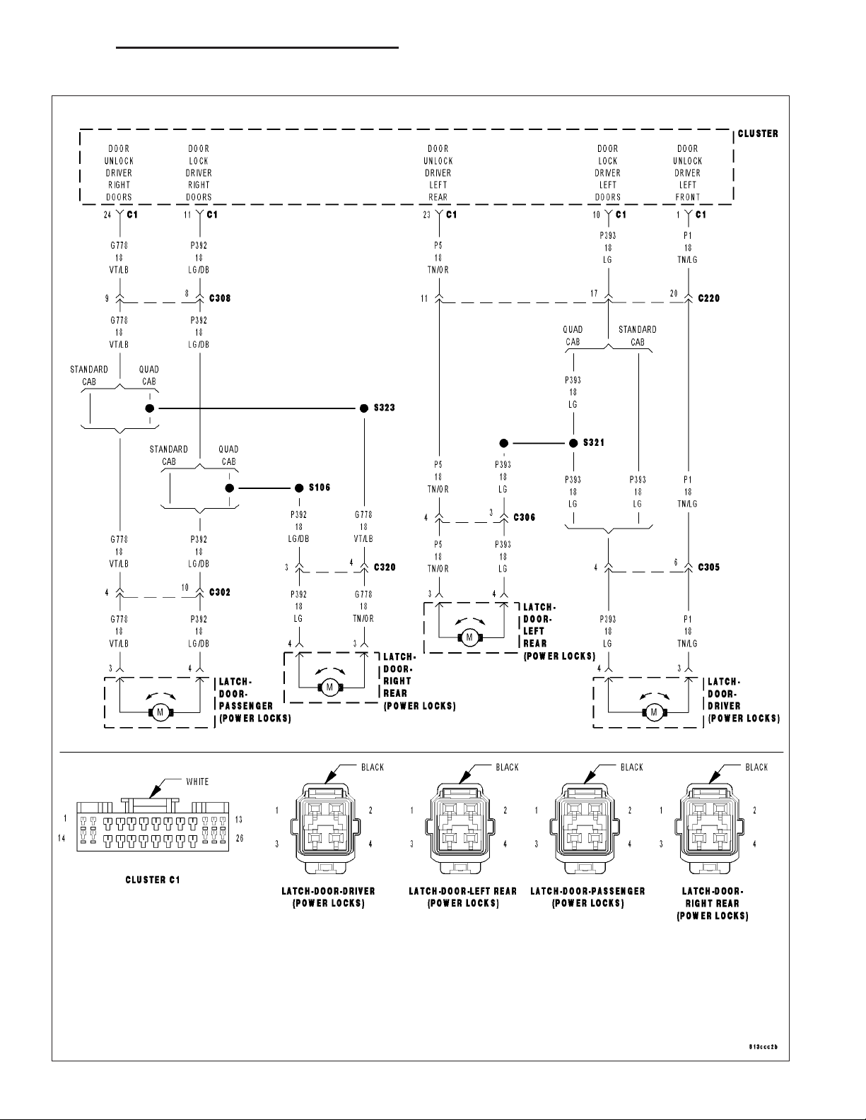
For the Power Door Lock circuit diagram (Refer to 8 - ELECTRICAL/POWER LOCKS - SCHEMATICS AND DIAGRAMS).
For a complete wiring diagram Refer to Section 8W.
• When Monitored:
Whenever the instrument cluster is awake.
• Set Condition:
The instrument cluster monitors the door lock output circuits and when one of them is shorted to ground or to
voltage, this code will set. This code will only set when the door locks are actuated.
Possible Causes
(P392) DOOR LOCK DRIVER RIGHT DOORS SHORTED TO (G778) DOOR UNLOCK DRIVER RIGHT DOORS
(P393) DOOR LOCK DRIVER LEFT DOORS SHORTED TO (P5) DOOR UNLOCK DRIVER LEFT REAR
(P393) DOOR LOCK DRIVER LEFT DOORS SHORT TO GROUND
(P392) DOOR LOCK DRIVER RIGHT DOORS SHORT TO GROUND
(P392) DOOR LOCK DRIVER RIGHT DOORS SHORT TO VOLTAGE
(P393) DOOR LOCK DRIVER LEFT DOORS SHORT TO VOLTAGE
DOOR LATCH
INSTRUMENT CLUSTER
Diagnostic Test
DTC PRESENT
1.
Turn the ignition on.
With the DRBIIIT, record and erase DTC’s.
With the DRBIIIT, read DTC’s.
Operate the door locks several times from a door
lock switch while monitoring the DRBIIIT.
Does the DRBIIIT display ALL DOOR LOCK
OUTPUT SHORT TO GROUND OR VOLTAGE?
Yes >>
No >>
Go To 2
Using the wiring diagram/schematic as
a guide, inspect the wiring and connectors. Check for any possible shorted
conditions between the instrument cluster and the door lock motors.
Perform BODY VERIFICATION TEST VER 1. (Refer to 8 - ELECTRICAL/
ELECTRONIC CONTROL MODULES/
FRONT CONTROL MODULE DIAGNOSIS AND TESTING)
Page 4
8N - 4 POWER LOCKS - ELECTRICAL DIAGNOSTICS DR/DH
ALL DOOR LOCK OUTPUT CIRCUIT SHORT TO GROUND OR VOLTAGE (CONTINUED)
(P392) DOOR LOCK DRIVER RIGHT DOORS SHORTED TO (G778) DOOR UNLOCK DRIVER RIGHT
2.
DOORS
NOTE: If only one door motor is inoperative when the door locks
are actuated, disconnect that door latch connector and retest to
see if the DTC is still active. If it is not, replace that door latch.
Turn the ignition off.
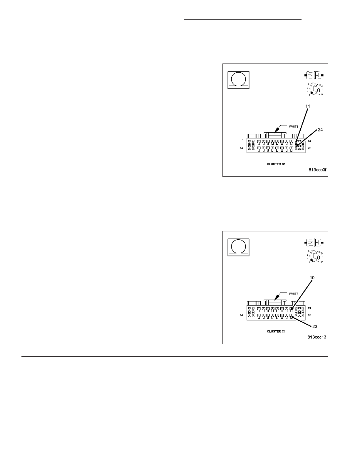
Disconnect the Instrument Cluster C1 connector.
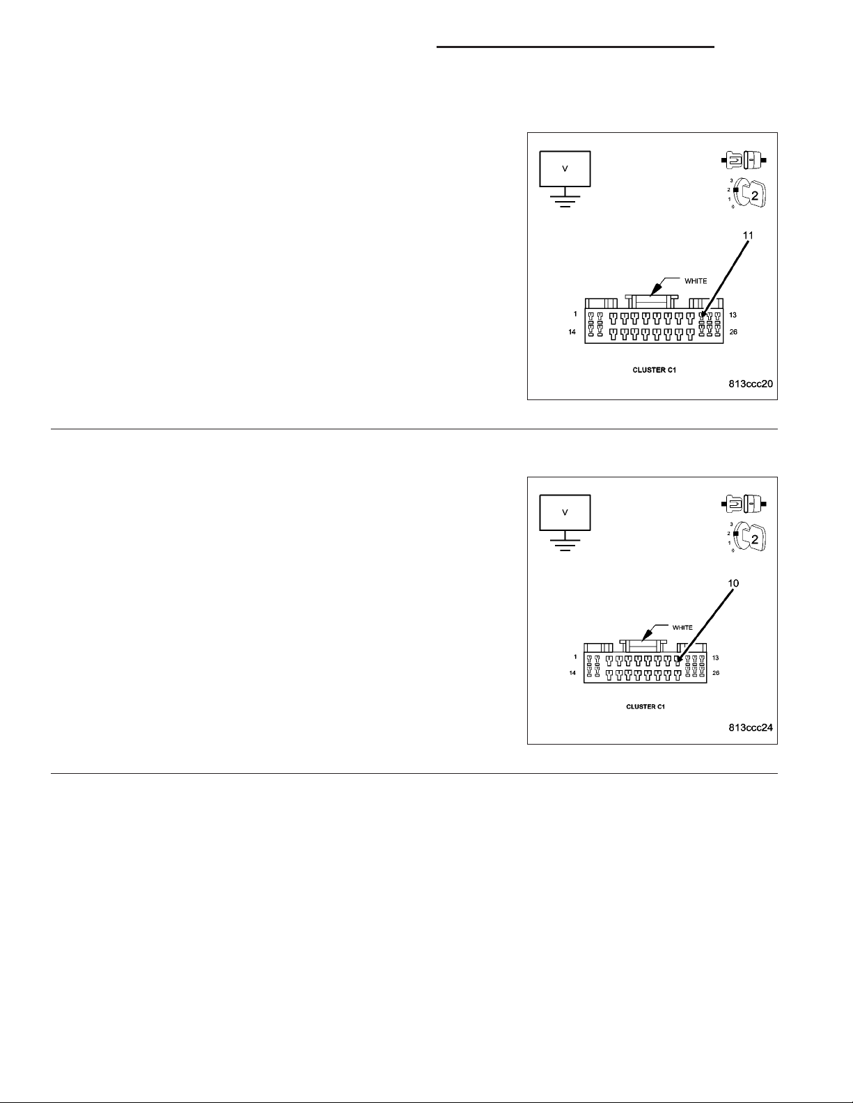
Measure the resistance between the (P392) Door Lock Driver Right
Doors circuit and the (G778) Door Unlock Driver Right Doors circuit in
the Instrument Cluster connector.
Is the resistance below 1.6 ohms?
Yes >>
No >>
(P393) DOOR LOCK DRIVER LEFT DOORS SHORTED TO THE (P5) DOOR UNLOCK DRIVER LEFT REAR
3.
NOTE: If this is a 2 door vehicle, answer NO to the question and
continue.
Measure the resistance between the (P393) Door Lock Driver Left
Doors circuit and the (P5) Door Unlock Driver Left Rear circuit in the
Instrument Cluster connector.
Is the resistance below 2.5 ohms?
Yes >>
No >>
Repair the (P392) Door Lock Driver Right Doors circuit for
a short to the (G778) Door Unlock Driver Right Doors circuit (could be a shorted motor).
Perform BODY VERIFICATION TEST - VER 1. (Refer to 8
- ELECTRICAL/ELECTRONIC CONTROL MODULES/
FRONT CONTROL MODULE - DIAGNOSIS AND TESTING)
Go To 3
Repair the (P393) Door Lock Driver Left Doors circuit for a
short to the (P5) Door Unlock Driver Left Rear circuit
(could be a shorted motor).
Perform BODY VERIFICATION TEST - VER 1. (Refer to 8
- ELECTRICAL/ELECTRONIC CONTROL MODULES/
FRONT CONTROL MODULE - DIAGNOSIS AND TESTING)
Go To 4
Page 5
DR/DH POWER LOCKS - ELECTRICAL DIAGNOSTICS 8N - 5
ALL DOOR LOCK OUTPUT CIRCUIT SHORT TO GROUND OR VOLTAGE (CONTINUED)
(P393) DOOR LOCK DRIVER LEFT DOORS SHORT TO GROUND
4.
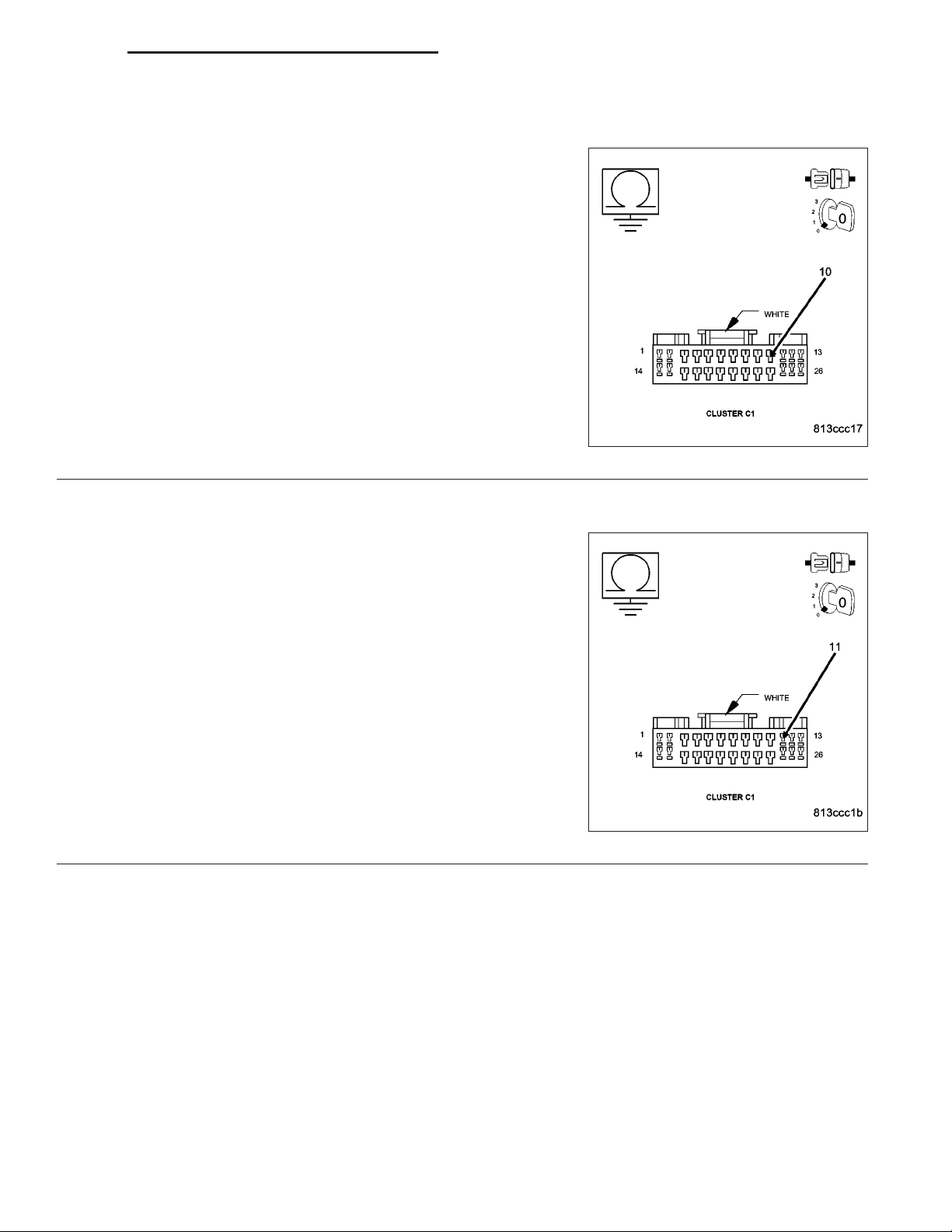
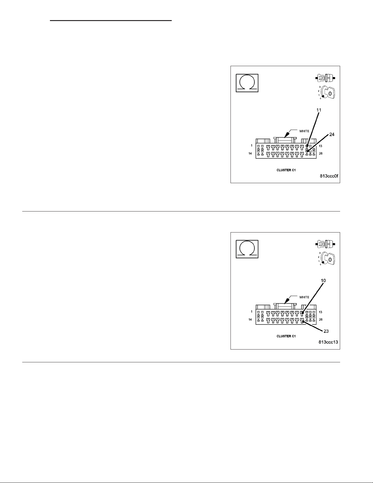
Measure the resistance between ground and the (P393) Door Lock
Driver Left Doors circuit in the Instrument Cluster C1 connector.
Is the resistance below 1000.0 ohms?
Yes >>
No >>
(P392) DOOR LOCK DRIVER RIGHT DOORS SHORT TO GROUND
5.
Measure the resistance between ground and the (P392) Door Lock
Driver Right Doors circuit in the Instrument Cluster C1 connector.
Is the resistance below 1000.0 ohms?
Yes >>
No >>
Repair the (P393) Door Lock Driver Left Doors circuit for a
short to ground. The short may be in the (P393) Door
Lock Driver Left Doors wire, the (P5) Door Unlock Driver
Left Rear Wire, instrument panel wiring or one of the left
side motors.
Perform BODY VERIFICATION TEST - VER 1. (Refer to 8
- ELECTRICAL/ELECTRONIC CONTROL MODULES/
FRONT CONTROL MODULE - DIAGNOSIS AND TESTING)
Go To 5
Repair the (P392) Door Lock Driver Right Doors circuit for
a short to ground. The short may be in the (P392) Door
Lock Driver Right Doors wire, the (G778) Door Unlock
Driver Right Doors wire or in a right side motor.
Perform BODY VERIFICATION TEST - VER 1. (Refer to 8
- ELECTRICAL/ELECTRONIC CONTROL MODULES/
FRONT CONTROL MODULE - DIAGNOSIS AND TESTING)
Go To 6
Page 6
8N - 6 POWER LOCKS - ELECTRICAL DIAGNOSTICS DR/DH
ALL DOOR LOCK OUTPUT CIRCUIT SHORT TO GROUND OR VOLTAGE (CONTINUED)
(P392) DOOR LOCK DRIVER RIGHT DOORS SHORT TO VOLTAGE
6.
Turn the ignition on.
Measure the voltage between ground and the (P392) Door Lock Driver
Right Doors circuit.
Is there any voltage present?
Yes >>
No >>
(P393) DOOR LOCK DRIVER LEFT DOORS SHORT TO VOLTAGE
7.
Measure the voltage between ground and the (P393) Door Lock Driver
Left Doors circuit.
Is there any voltage present?
Yes >>
No >>
Repair the (P392) Door Lock or (G778) Unlock Driver
Right Doors circuit for a short to voltage.
Perform BODY VERIFICATION TEST - VER 1. (Refer to 8
- ELECTRICAL/ELECTRONIC CONTROL MODULES/
FRONT CONTROL MODULE - DIAGNOSIS AND TESTING)
Go To 7
Repair the (P393) Door Lock or (P5) Door Unlock Driver
Left Rear or (P1) Door Unlock Driver Left Front circuit for
a short to voltage.
Perform BODY VERIFICATION TEST - VER 1. (Refer to 8
- ELECTRICAL/ELECTRONIC CONTROL MODULES/
FRONT CONTROL MODULE - DIAGNOSIS AND TESTING)
Replace the Instrument Cluster.
Perform BODY VERIFICATION TEST - VER 1. (Refer to 8
- ELECTRICAL/ELECTRONIC CONTROL MODULES/
FRONT CONTROL MODULE - DIAGNOSIS AND TESTING)
Page 7
DR/DH POWER LOCKS - ELECTRICAL DIAGNOSTICS 8N - 7
ALL DOOR UNLOCK OUTPUT CIRCUIT SHORT TO GROUND OR VOLTAGE
Page 8
8N - 8 POWER LOCKS - ELECTRICAL DIAGNOSTICS DR/DH
ALL DOOR UNLOCK OUTPUT CIRCUIT SHORT TO GROUND OR VOLTAGE (CONTINUED)
For the Power Door Lock circuit diagram (Refer to 8 - ELECTRICAL/POWER LOCKS - SCHEMATICS AND DIAGRAMS).
For a complete wiring diagram Refer to Section 8W.
• When Monitored:
Whenever the instrument cluster is awake.
• Set Condition:
The instrument cluster monitors the door unlock output circuits and when one of them is shorted to ground or
to voltage, this code will set. This code will only set when the door locks are actuated.
Possible Causes
(P392) DOOR LOCK DRIVER RIGHT DOORS SHORTED TO (G778) DOOR UNLOCK DRIVER RIGHT DOORS
(P393) DOOR LOCK DRIVER LEFT DOORS SHORTED TO (P5) DOOR UNLOCK DRIVER LEFT REAR
DOOR UNLOCK DRIVER RIGHT DOORS CIRCUIT SHORT TO GROUND
DOOR UNLOCK DRIVER LEFT REAR CIRCUIT SHORT TO GROUND
DOOR UNLOCK DRIVER RIGHT DOORS SHORT TO VOLTAGE
DOOR UNLOCK DRIVER LEFT REAR SHORT TO VOLTAGE
DOOR LATCH
INSTRUMENT CLUSTER
Diagnostic Test
DTC PRESENT
1.
Turn the ignition on.
With the DRBIIIT, record and erase DTC’s.
With the DRBIIIT, read DTC’s.
Operate the door locks several times from a door lock
switch while monitoring the DRBIIIT.
Does the DRBIIIT display ALL DOOR UNLOCK
OUTPUT SHORT TO GROUND OR VOLTAGE?
Yes >>
No >>
Go To 2
Using the wiring diagram/schematic as a
guide, inspect the wiring and connectors.
Check for any possible shorted conditions
between the instrument cluster and the
door lock motors.
Perform BODY VERIFICATION TEST VER 1. (Refer to 8 - ELECTRICAL/ELECTRONIC CONTROL MODULES/FRONT
CONTROL MODULE - DIAGNOSIS AND
TESTING)
Page 9
DR/DH POWER LOCKS - ELECTRICAL DIAGNOSTICS 8N - 9
ALL DOOR UNLOCK OUTPUT CIRCUIT SHORT TO GROUND OR VOLTAGE (CONTINUED)
(P392) DOOR LOCK DRIVER RIGHT DOORS SHORTED TO (G778) DOOR UNLOCK DRIVER RIGHT
2.
DOORS
NOTE: If only one motor is inoperative when the door locks are
actuated, disconnect that door latch connector and retest to see
if the DTC is still present. If it is not, replace that door latch.
Turn the ignition off.
Disconnect the Instrument Cluster C1 connector.
Measure the resistance between the (P392) Door Lock Driver Right
Doors circuit and the (G778) Door Unlock Driver Right Doors circuit in
the Instrument Cluster connector.
Is the resistance below 1.6 ohms?
Yes >>
No >>
(P393) DOOR LOCK DRIVER LEFT DOORS SHORTED TO (P5) DOOR UNLOCK DRIVER LEFT REAR
3.
NOTE: If this is a 2 door vehicle, answer NO to the question and
continue.
Measure the resistance between the (P393) Door Lock Driver Left
Doors circuit and the (P5) Door Unlock Driver Left Rear circuit in the
Instrument Cluster connector.
Is the resistance below 2.5 ohms?
Yes >>
No >>
Repair the (P392) Door Lock Driver Right Doors circuit for
a short to the (G778) Door Unlock Driver Right Doors circuit (could be a shorted motor).
Perform BODY VERIFICATION TEST - VER 1. (Refer to 8
- ELECTRICAL/ELECTRONIC CONTROL MODULES/
FRONT CONTROL MODULE - DIAGNOSIS AND TESTING)
Go To 3
Repair the (P393) Door Lock Driver Left Doors circuit for a
short to the (P5) Door Unlock Driver Left Rear or the (P1)
Door Unlock Driver Left Front circuit (could be a shorted
motor).
Perform BODY VERIFICATION TEST - VER 1. (Refer to 8
- ELECTRICAL/ELECTRONIC CONTROL MODULES/
FRONT CONTROL MODULE - DIAGNOSIS AND TESTING)
Go To 4
Page 10

8N - 10 POWER LOCKS - ELECTRICAL DIAGNOSTICS DR/DH
ALL DOOR UNLOCK OUTPUT CIRCUIT SHORT TO GROUND OR VOLTAGE (CONTINUED)
(G778) DOOR UNLOCK DRIVER RIGHT DOORS CIRCUIT SHORT TO GROUND
4.
Measure the resistance between ground and the (G778) Door Unlock
Driver Right Doors circuit in the Instrument Cluster C1 connector.
Is the resistance below 1000.0 ohms?
Yes >>
No >>
(P5) DOOR UNLOCK DRIVER LEFT REAR CIRCUIT SHORT TO GROUND
5.
NOTE: If this is a 2 door vehicle, answer NO to the question and
continue.
Measure the resistance between ground and the (P5) Door Unlock
Driver Left Rear circuit in the Instrument Cluster C1 connector.
Is the resistance below 1000.0 ohms?
Yes >>
No >>
Repair the (G778) Door Unlock Driver Right Doors circuit
for a short to ground. The short may be in the (G778)
Door Unlock Driver Right Doors wire, the (P392) Door
Lock Driver Right Doors wire or a right side door lock
motor.
Perform BODY VERIFICATION TEST - VER 1. (Refer to 8
- ELECTRICAL/ELECTRONIC CONTROL MODULES/
FRONT CONTROL MODULE - DIAGNOSIS AND TESTING)
Go To 5
Repair the (P5) Door Unlock Driver Left Rear circuit for a
short to ground. The short may be in the (P5) Door Unlock
Driver Left Rear wire, the (P393) Door Lock Driver Left
Doors wire or in a left side door lock motor.
Perform BODY VERIFICATION TEST - VER 1. (Refer to 8
- ELECTRICAL/ELECTRONIC CONTROL MODULES/
FRONT CONTROL MODULE - DIAGNOSIS AND TESTING)
Go To 6
Page 11
DR/DH POWER LOCKS - ELECTRICAL DIAGNOSTICS 8N - 11
ALL DOOR UNLOCK OUTPUT CIRCUIT SHORT TO GROUND OR VOLTAGE (CONTINUED)
(G778) DOOR UNLOCK DRIVER RIGHT DOORS SHORT TO VOLTAGE
6.
Turn the ignition on.
Measure the voltage between ground and the (G778) Door Unlock
Driver Right Doors circuit.
Is there any voltage present?
Yes >>
No >>
(P5) DOOR UNLOCK DRIVER LEFT REAR SHORT TO VOLTAGE
7.
NOTE: If this a 2 Door vehicle, answer NO to the question and
continue.
Measure the voltage between ground and the (P5) Door Unlock Driver
Left Rear circuit.
Is there any voltage present?
Yes >>
No >>
Repair the (P392) Door Lock or (G778) Door Unlock
Driver Right Doors circuit for a short to voltage.
Perform BODY VERIFICATION TEST - VER 1. (Refer to 8
- ELECTRICAL/ELECTRONIC CONTROL MODULES/
FRONT CONTROL MODULE - DIAGNOSIS AND TESTING)
Go To 7
Repair the (P393) Door Lock Driver Left Doors or the (P5)
Door Unlock Driver Left Rear circuit for a short to voltage.
Perform BODY VERIFICATION TEST - VER 1. (Refer to 8
- ELECTRICAL/ELECTRONIC CONTROL MODULES/
FRONT CONTROL MODULE - DIAGNOSIS AND TESTING).
Replace the Instrument Cluster.
Perform BODY VERIFICATION TEST - VER 1. (Refer to 8
- ELECTRICAL/ELECTRONIC CONTROL MODULES/
FRONT CONTROL MODULE - DIAGNOSIS AND TESTING)
Page 12
8N - 12 POWER LOCKS - ELECTRICAL DIAGNOSTICS DR/DH
DRIVER DOOR UNLOCK OUTPUT CIRCUIT SHORT TO GROUND OR VOLTAGE
Page 13
DR/DH POWER LOCKS - ELECTRICAL DIAGNOSTICS 8N - 13
DRIVER DOOR UNLOCK OUTPUT CIRCUIT SHORT TO GROUND OR VOLTAGE (CONTINUED)
For the Power Door Lock circuit diagram (Refer to 8 - ELECTRICAL/POWER LOCKS - SCHEMATICS AND DIAGRAMS)
For a complete wiring diagram Refer to Section 8W.
• When Monitored:
Whenever the instrument cluster is awake.
• Set Condition:
The instrument cluster monitors the driver door unlock output circuit and when it is shorted to ground or to
voltage, this code will set. This code will only set when the door locks are actuated.
Possible Causes
(P393) DOOR LOCK DRIVER LEFT DOORS SHORTED TO (P1) DOOR UNLOCK DRIVER LEFT FRONT
(P1) DOOR UNLOCK DRIVER LEFT FRONT WIRE SHORT TO GROUND
(P393) DOOR LOCK DRIVER LEFT DOORS WIRE SHORT TO GROUND
(P393) DOOR LOCK DRIVER LEFT DOORS WIRE SHORTED TO VOLTAGE
(P1) DOOR LOCK DRIVER LEFT FRONT WIRE SHORTED TO VOLTAGE
DRIVER DOOR LATCH
INSTRUMENT CLUSTER
Diagnostic Test
DTC PRESENT
1.
Turn the ignition on.
With the DRBIIIT, record and erase DTC’s.
With the DRBIIIT, read DTC’s.
Operate the door locks several times from a door lock
switch while monitoring the DRBIIIT.
Does the DRBIIIT display DRIVER DOOR
UNLOCK OUTPUT CIRCUIT SHORT TO GROUND
OR VOLTAGE?
Yes >>
No >>
Go To 2
Using the wiring diagram/schematic as a
guide, inspect the wiring and connectors.
Check for any possible shorted conditions
between the instrument cluster and the
driver door lock motor.
Perform BODY VERIFICATION TEST VER 1. (Refer to 8 - ELECTRICAL/ELECTRONIC CONTROL MODULES/FRONT
CONTROL MODULE - DIAGNOSIS AND
TESTING)
Page 14

8N - 14 POWER LOCKS - ELECTRICAL DIAGNOSTICS DR/DH
DRIVER DOOR UNLOCK OUTPUT CIRCUIT SHORT TO GROUND OR VOLTAGE (CONTINUED)
(P393) DOOR LOCK DRIVER LEFT DOORS SHORTED TO (P1) DOOR UNLOCK DRIVER LEFT FRONT
2.
Turn the ignition off.
Disconnect the Instrument Cluster C1 connector.
Measure the resistance between the (P1) Door Unlock Driver Left
Front circuit and the (P393) Door Lock Driver Left Doors circuit in the
Instrument Cluster C1 connector.
Is the resistance below 3.0 ohms?
Yes >>
No >>
(P1) DOOR UNLOCK DRIVER LEFT FRONT CIRCUIT SHORTED TO GROUND
3.
Measure the resistance between ground and the (P1) Door Unlock
Driver Left Front circuit in the Instrument Cluster C1 connector.
Is the resistance below 1000.0 ohms?
No >>
Yes >>
Repair the (P393) Door Lock Driver Left Doors circuit for a
short to the (P1) Door Unlock Driver Left Front circuit
(could be a shorted motor).
Perform BODY VERIFICATION TEST - VER 1. (Refer to 8
- ELECTRICAL/ELECTRONIC CONTROL MODULES/
FRONT CONTROL MODULE - DIAGNOSIS AND TESTING)
Go To 3
Go To 6
Go To 4
Page 15
DR/DH POWER LOCKS - ELECTRICAL DIAGNOSTICS 8N - 15
DRIVER DOOR UNLOCK OUTPUT CIRCUIT SHORT TO GROUND OR VOLTAGE (CONTINUED)
(P1) DOOR UNLOCK DRIVER LEFT FRONT WIRE SHORT TO GROUND
4.
Disconnect the Driver Door Lock Motor connector.
Measure the resistance between ground and the (P1) Door Unlock
Driver Left Front wire in the Instrument Cluster C1 connector.
Is the resistance below 1000.0 ohms?
Yes >>
No >>
(P393) DOOR LOCK DRIVER LEFT DOORS WIRE SHORT TO GROUND
5.
Measure the resistance between ground and the (P393) Door Lock
Driver Left Doors circuit in the Instrument Cluster C1 connector.
Is the resistance below 1000.0 ohms?
Yes >>
No >>
Repair the (P1) Door Unlock Driver Left Front wire for a
short to ground.
Perform BODY VERIFICATION TEST - VER 1. (Refer to 8
- ELECTRICAL/ELECTRONIC CONTROL MODULES/
FRONT CONTROL MODULE - DIAGNOSIS AND TESTING)
Go To 5
Repair the (P393) Door Lock Driver Left Doors wire for a
short to ground.
Perform BODY VERIFICATION TEST - VER 1. (Refer to 8
- ELECTRICAL/ELECTRONIC CONTROL MODULES/
FRONT CONTROL MODULE - DIAGNOSIS AND TESTING)
Replace the Driver Door Latch.
Perform BODY VERIFICATION TEST - VER 1. (Refer to 8
- ELECTRICAL/ELECTRONIC CONTROL MODULES/
FRONT CONTROL MODULE - DIAGNOSIS AND TESTING)
Page 16
8N - 16 POWER LOCKS - ELECTRICAL DIAGNOSTICS DR/DH
DRIVER DOOR UNLOCK OUTPUT CIRCUIT SHORT TO GROUND OR VOLTAGE (CONTINUED)
(P1) DOOR UNLOCK DRIVER LEFT FRONT OR (P393) DOOR LOCK DRIVER LEFT DOORS SHORTED TO
6.
VOLTAGE
Turn the ignition on.
Measure the voltage between ground and the (P1) Door Unlock Driver
Left Front circuit.
Is there any voltage present?
Yes >>
No >>
Repair the (P393) Door Lock Driver Left Doors or (P1)
Door Unlock Driver Left Front circuit for a short to voltage.
Perform BODY VERIFICATION TEST - VER 1. (Refer to 8
- ELECTRICAL/ELECTRONIC CONTROL MODULES/
FRONT CONTROL MODULE - DIAGNOSIS AND TESTING)
Replace the Instrument Cluster.
Perform BODY VERIFICATION TEST - VER 1 (Refer to 8
- ELECTRICAL/ELECTRONIC CONTROL MODULES/
FRONT CONTROL MODULE - DIAGNOSIS AND TESTING)
Page 17
DR/DH POWER LOCKS - ELECTRICAL DIAGNOSTICS 8N - 17
DRIVER CYLINDER LOCK SWITCH INPUT CIRCUIT SHORTED (WITH VTSS ONLY)
Page 18

8N - 18 POWER LOCKS - ELECTRICAL DIAGNOSTICS DR/DH
DRIVER CYLINDER LOCK SWITCH INPUT CIRCUIT SHORTED (WITH VTSS ONLY) (CONTINUED)
For the Power Door Locks circuit diagram (Refer to 8 - ELECTRICAL/POWER LOCKS - SCHEMATICS AND DIAGRAMS).
For a complete wiring diagram Refer to Section 8W.
• When Monitored:
At all times when battery power is supplied to the Instrument Cluster.
• Set Condition:
When the Instrument Cluster senses voltage to the driver cylinder lock switch below 0.25 volts for over 10
seconds.
Possible Causes
(G163) DRIVER CYLINDER LOCK SWITCH MUX CIRCUIT SHORT TO GROUND
CYLINDER LOCK SWITCH SHORTED
INSTRUMENT CLUSTER
Diagnostic Test
DTC PRESENT
1.
Turn the ignition on.
With the DRBIIIT, record and erase DTC’s.
With the DRBIIIT, read DTC’s.
Operate the door locks several times from the Driver
Cylinder Lock Switch by cycling the key clockwise
while monitoring the DRBIIIT.
Does the DRBIIIT display DRIVER CYL LOCK SW
INPUT CIRCUIT SHORTED?
Yes >>
No >>
Go To 2
Using the wiring diagram/schematic as a
guide, inspect the wiring and connectors.
Perform BODY VERIFICATION TEST -
VER 1. (Refer to 8 - ELECTRICAL/ELECTRONIC CONTROL MODULES/FRONT
CONTROL MODULE - DIAGNOSIS AND
TESTING)
Page 19
DR/DH POWER LOCKS - ELECTRICAL DIAGNOSTICS 8N - 19
DRIVER CYLINDER LOCK SWITCH INPUT CIRCUIT SHORTED (WITH VTSS ONLY) (CONTINUED)
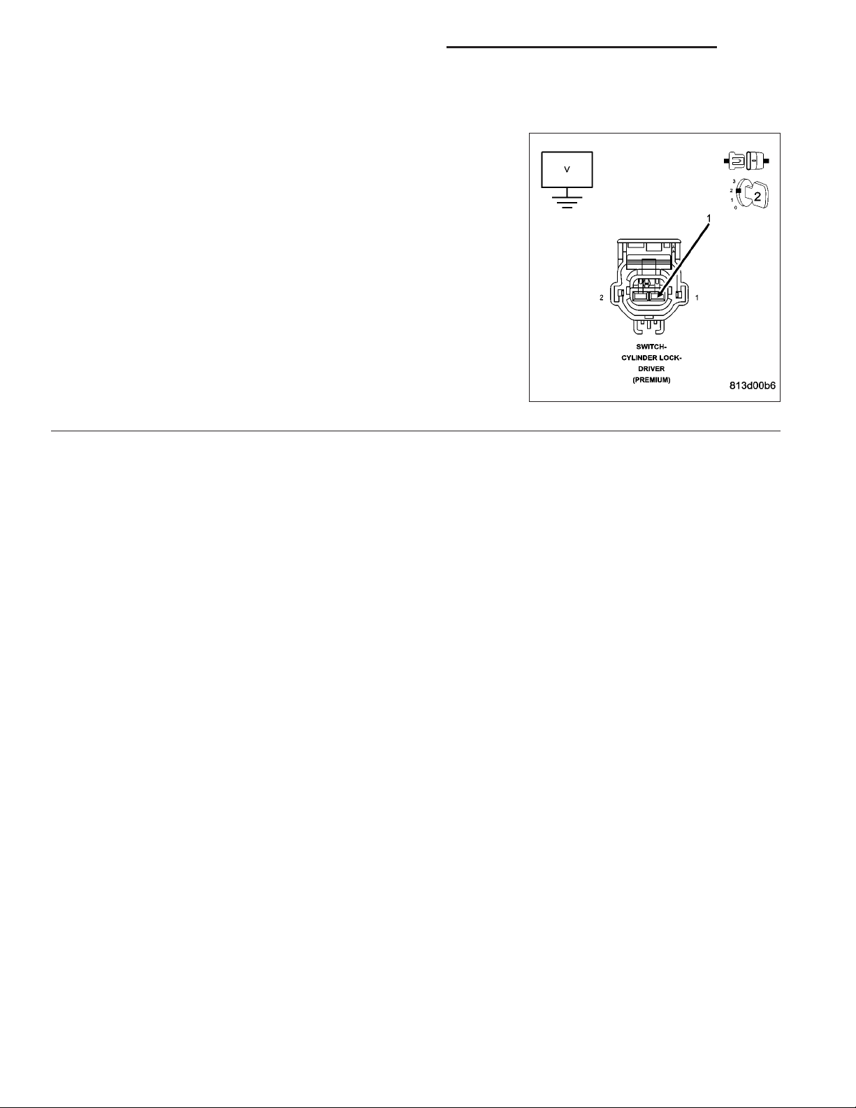
CYLINDER LOCK SWITCH SHORTED
2.
Disconnect the Driver Cylinder Lock Switch connector.
With the DRBIIIT in Sensors, read the DRV CYL LOCK SW MUX cir-
cuit
Is the voltage above 4.8 volts?
Yes >>
No >>
(G163) DRIVER CYLINDER LOCK SWITCH MUX SHORTED
3.
Disconnect the Driver Cylinder Lock Switch connector.
Disconnect the Instrument Cluster C2. connector.
Measure the resistance between (G163) Driver Cylinder Lock Switch
Mux circuit and ground.
Is the resistance below 1000.0 ohms?
Yes >>
No >>
Replace the Cylinder Lock Switch.
Perform BODY VERIFICATION TEST - VER 1. (Refer to 8
- ELECTRICAL/ELECTRONIC CONTROL MODULES/
FRONT CONTROL MODULE - DIAGNOSIS AND TESTING)
Go To 3
Repair the (G163) Driver Cylinder Lock Switch Mux circuit
for a short to ground.
Perform BODY VERIFICATION TEST - VER 1. (Refer to 8
- ELECTRICAL/ELECTRONIC CONTROL MODULES/
FRONT CONTROL MODULE - DIAGNOSIS AND TESTING)
Replace the Instrument Cluster. Perform BODY VERIFICATION TEST - VER 1. (Refer to 8 - ELECTRICAL/ELECTRONIC CONTROL MODULES/FRONT CONTROL
MODULE - DIAGNOSIS AND TESTING)
Page 20
8N - 20 POWER LOCKS - ELECTRICAL DIAGNOSTICS DR/DH
DRIVER CYLINDER LOCK SWITCH INPUT STUCK (WITH VTSS ONLY)
Page 21
DR/DH POWER LOCKS - ELECTRICAL DIAGNOSTICS 8N - 21
DRIVER CYLINDER LOCK SWITCH INPUT STUCK (WITH VTSS ONLY) (CONTINUED)
For the Power Door Locks circuit diagram. (Refer to 8 - ELECTRICAL/ELECTRONIC CONTROL MODULES/FRONT
CONTROL MODULE - DIAGNOSIS AND TESTING)
For a complete wiring diagram Refer to Section 8W.
• When Monitored:
At all times when battery power is supplied to the Instrument Cluster.
• Set Condition:
When the Instrument Cluster senses voltage to the driver cylinder lock switch between 1.3 and 3.75 volts for
over 10 seconds.
Possible Causes
DRIVER CYLINDER LOCK SWITCH MUX CIRCUIT PARTIAL SHORT TO GROUND
CYLINDER LOCK SWITCH STUCK
INSTRUMENTT CLUSTER
Diagnosttic Test
DTC PRESENT
1.
Turn the ignition on.
With the DRBIIIT, record and erase DTC’s.
With the DRBIIIT, read DTC’s.
Operate the door locks several times from the Driver
Cylinder Lock Switch by cycling the key in both directions while monitoring the DRBIIIT.
Does the DRBIIIT display DRV CYL LOCK SW
INPUT CIRCUIT STUCK?
Yes >>
No >>
CYLINDER LOCK SWITCH SHORTED
2.
With the DRBIIIT in Sensors, read the DRV CYL LOCK SW MUX circuit
Does the DRBIIIT display voltage between 1.3 and 4.15 volts?
No >>
Yes >>
Go To 2
Using the wiring diagram/schematic as a
guide, inspect the wiring and connectors.
Perform BODY VERIFICATION TEST -
VER 1. (Refer to 8 - ELECTRICAL/ELECTRONIC CONTROL MODULES/FRONT
CONTROL MODULE - DIAGNOSIS AND
TESTING)
Replace the Instrument Cluster.
Perform BODY VERIFICATION TEST - VER 1. (Refer to 8 - ELECTRICAL/ELECTRONIC CONTROL
MODULES/FRONT CONTROL MODULE - DIAGNOSIS AND TESTING)
Go To 3
Page 22
8N - 22 POWER LOCKS - ELECTRICAL DIAGNOSTICS DR/DH
DRIVER CYLINDER LOCK SWITCH INPUT STUCK (WITH VTSS ONLY) (CONTINUED)
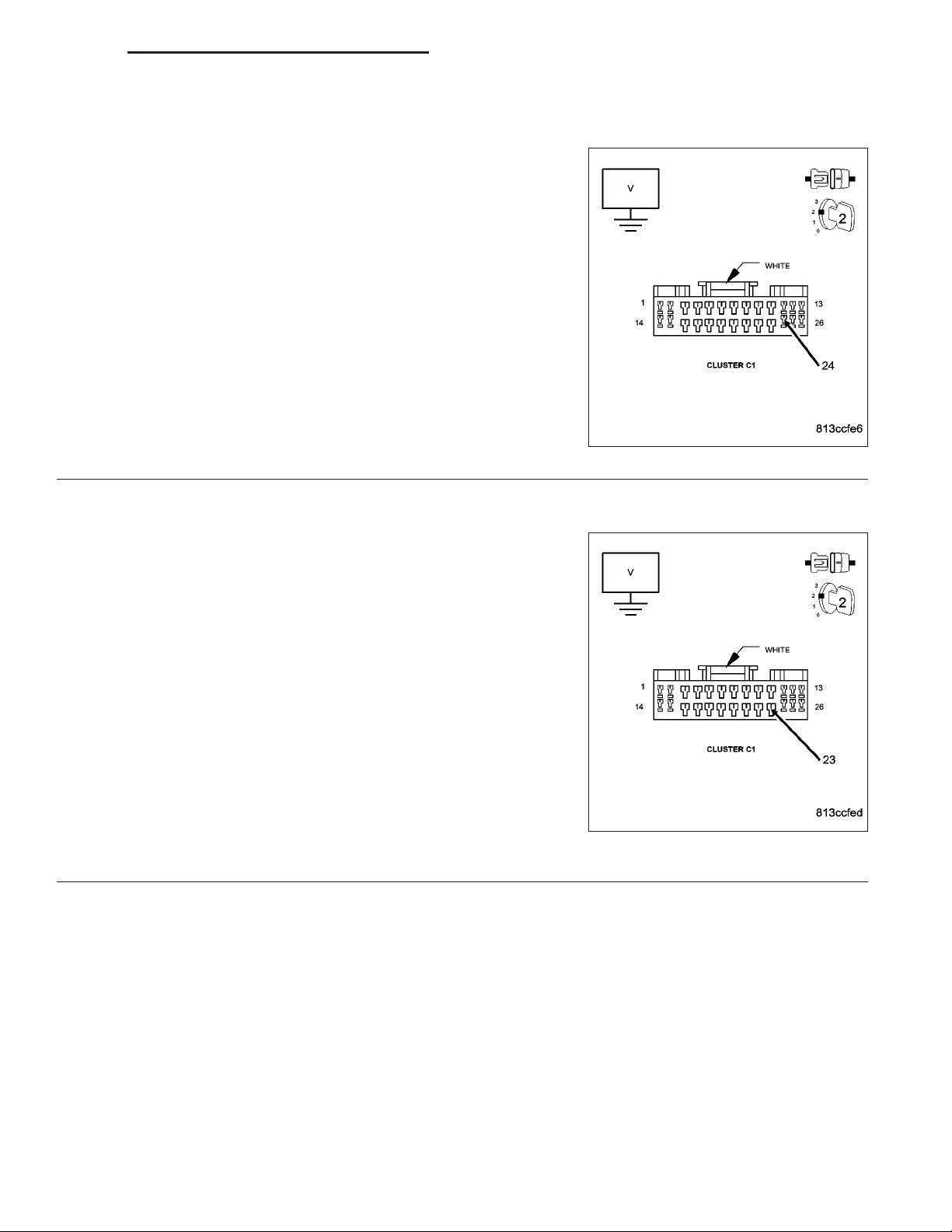
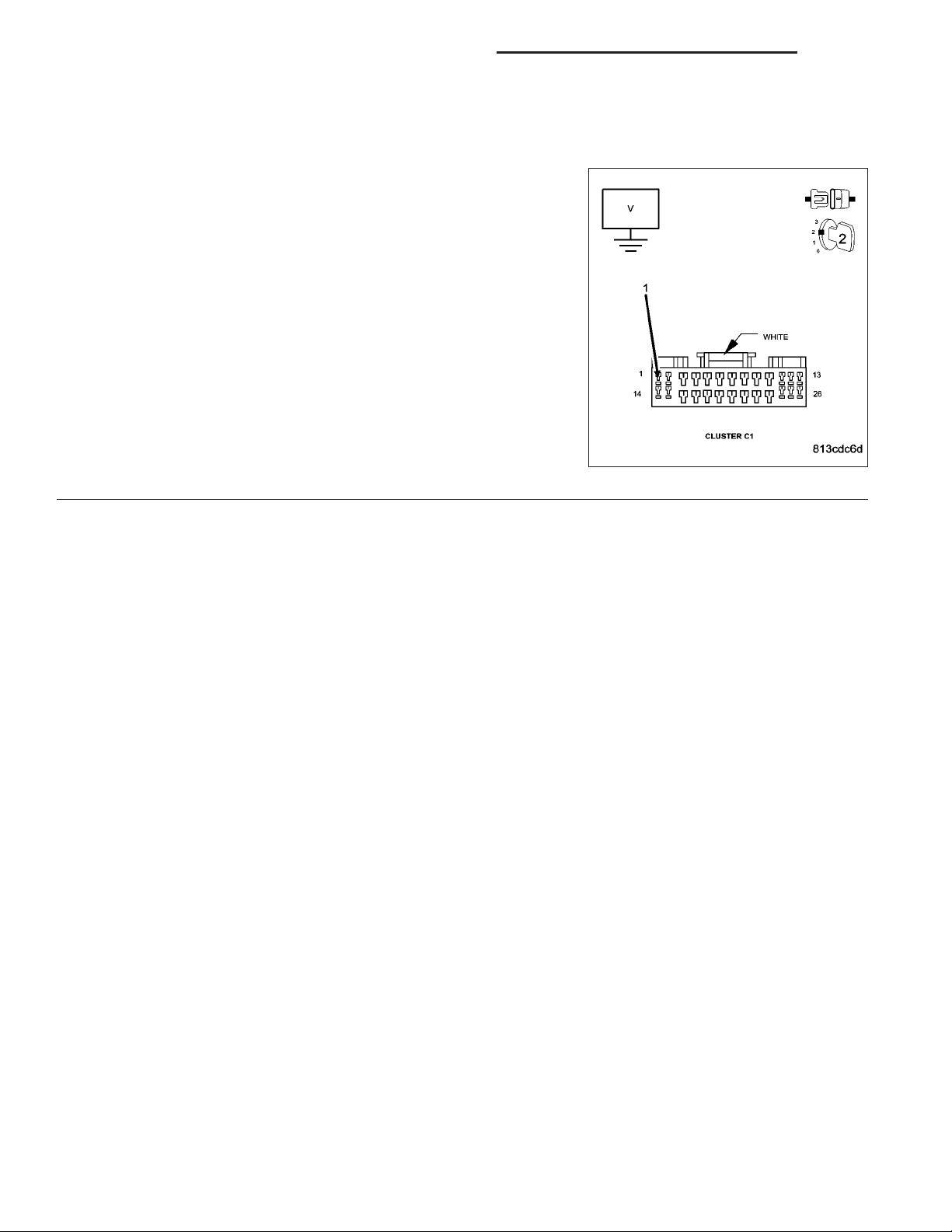
(G164) DRIVER CYLINDER LOCK SWITCH MUX SHORTED
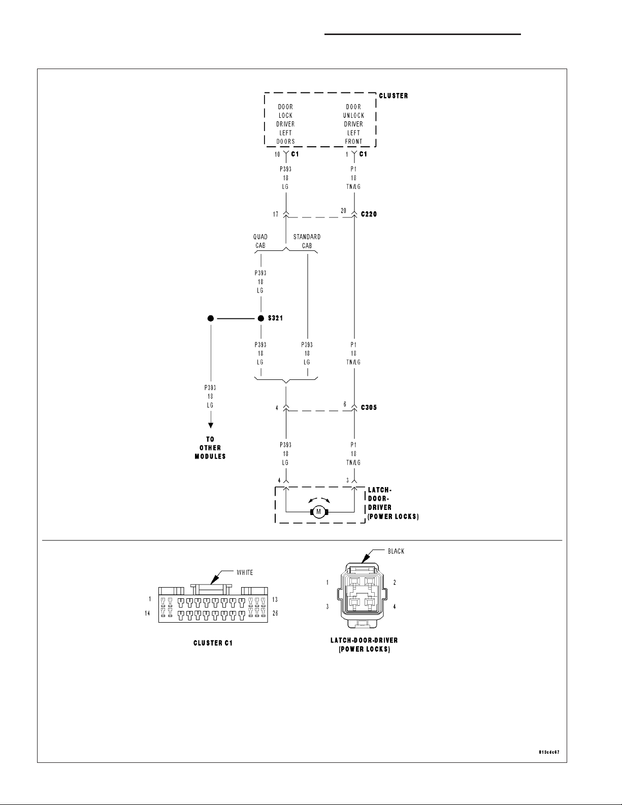
3.
Disconnect the Driver Cylinder Lock Switch connector.
Measure the voltage between (G163) Driver Cylinder Lock Switch Mux
circuit and ground.
Is the voltage above 4.9 volts?
No >>
Yes >>
Repair the (G163) Driver Cylinder Lock Switch Mux circuit
for a partial short to ground.
Perform BODY VERIFICATION TEST - VER 1. (Refer to 8
- ELECTRICAL/ELECTRONIC CONTROL MODULES/
FRONT CONTROL MODULE - DIAGNOSIS AND TESTING)
Replace the Cylinder Lock Switch. Perform BODY VERIFICATION TEST - VER 1. (Refer to 8 - ELECTRICAL/ELECTRONIC CONTROL MODULES/FRONT CONTROL
MODULE - DIAGNOSIS AND TESTING)
Page 23
DR/DH POWER LOCKS - ELECTRICAL DIAGNOSTICS 8N - 23
DRIVER DOOR LOCK SWITCH INPUT CIRCUIT OPEN OR SHORT TO VOLTAGE
Page 24
8N - 24 POWER LOCKS - ELECTRICAL DIAGNOSTICS DR/DH
DRIVER DOOR LOCK SWITCH INPUT CIRCUIT OPEN OR SHORT TO VOLTAGE (CONTINUED)
For the Power Door Lock circuit diagram (Refer to 8 - ELECTRICAL/POWER LOCKS - SCHEMATICS AND DIAGRAMS) (Refer to ).
For a complete wiring diagram Refer to Section 8W.
• When Monitored:
At all times when battery power is supplied to the Instrument Cluster.
• Set Condition:
When the Instrument Cluster senses voltage to the driver door lock switch above 4.85 volts.
Possible Causes
(G161) DRIVER DOOR LOCK SWITCH WIRE SHORT TO VOLTAGE
(G161) DRIVER DOOR LOCK SWITCH MUX CIRCUIT OPEN
DOOR LOCK SWITCH GROUND OPEN
DOOR LOCK SWITCH SHORT TO VOLTAGE
DOOR LOCK SWITCH OPEN
INSTRUMENT CLUSTER - VOLTAGE TO HIGH
INSTRUMENT CLUSTER - DRIVER DOOR LOCK SWITCH VOLTAGE LOW
Diagnostic Test
DTC PRESENT
1.
Turn the ignition on.
With the DRBIIIT, record and erase DTC’s.
With the DRBIIIT, read DTC’s.
Operate the door locks from the Driver Door Lock
Switch while monitoring the DRBIIIT.
Does the DRBIIIT display DRIVER DOOR LOCK
SWITCH INPUT CIRCUIT OPEN OR SHORT TO
VOLTAGE?
Yes >>
No >>
Go To 2
Using the wiring diagram/schematic as a
guide, inspect the wiring and connectors.
Check for any possible loose connections
at the instrument cluster and the door lock
switch.
Perform BODY VERIFICATION TEST VER 1. (Refer to 8 - ELECTRICAL/ELECTRONIC CONTROL MODULES/FRONT
CONTROL MODULE - DIAGNOSIS AND
TESTING)
Page 25
DR/DH POWER LOCKS - ELECTRICAL DIAGNOSTICS 8N - 25
DRIVER DOOR LOCK SWITCH INPUT CIRCUIT OPEN OR SHORT TO VOLTAGE (CONTINUED)
INSTRUMENT CLUSTER - DRIVER DOOR LOCK SWITCH VOLTAGE LOW
2.
With the DRBIIIT in Sensors, read the DRV DOOR LOCK SW voltage.
Voltage reading is:
Above 5.2 volts
Go To 3
Between 4.9 and 5.1 volts
Go To 5
Below 4.8 volts
Replace the Instrument Cluster.
Perform BODY VERIFICATION TEST - VER 1. (Refer to 8 - ELECTRICAL/ELECTRONIC CONTROL
MODULES/FRONT CONTROL MODULE - DIAGNOSIS AND TESTING)
INSTRUMENT CLUSTER - VOLTAGE TO HIGH
3.
Turn the ignition off.
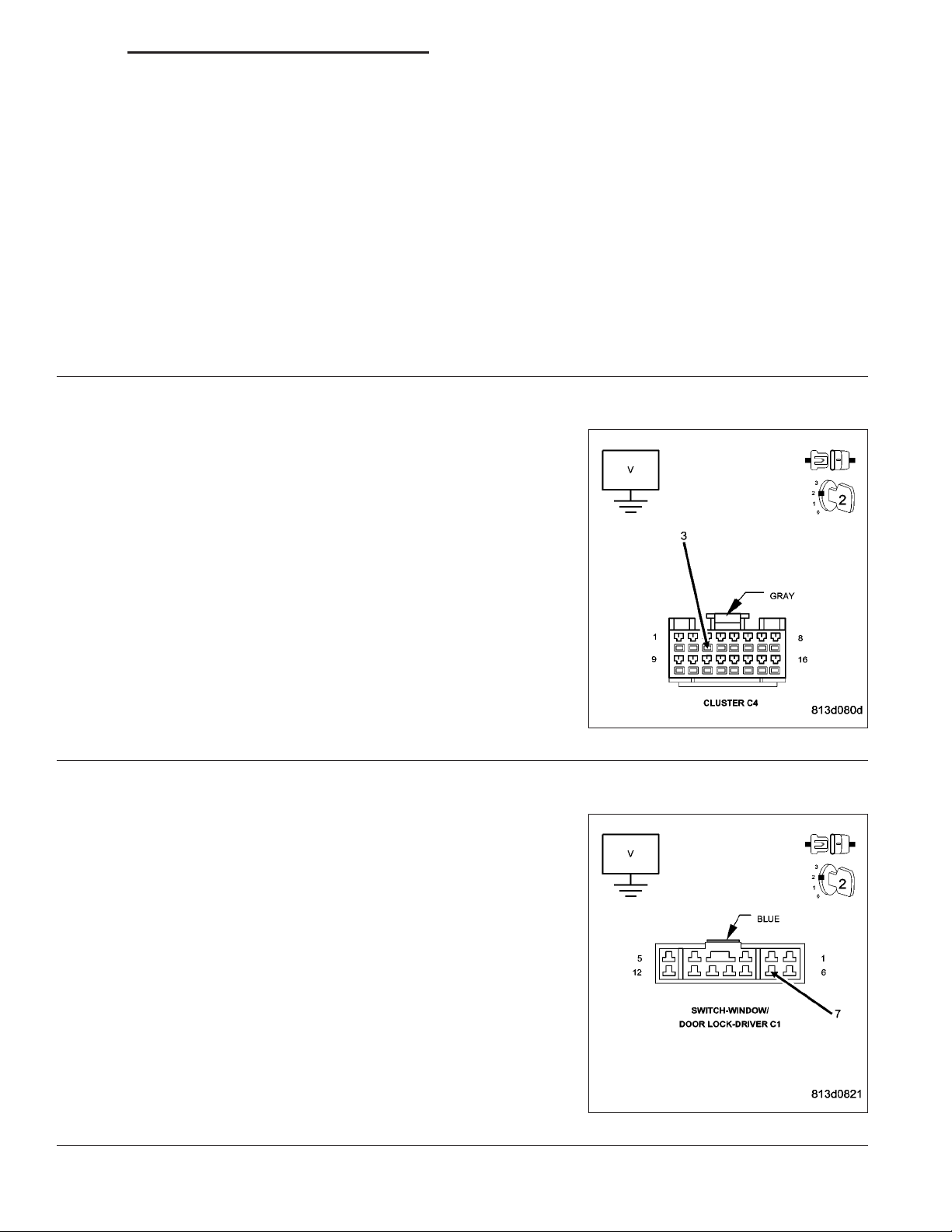
Disconnect the Instrument Cluster C4 connector.
Turn the ignition on.
Measure the voltage between (G161) Driver Door Lock Switch Mux
circuit and ground.
Is there any voltage present?
Yes >>
No >>
(G161) DRIVER DOOR LOCK SWITCH WIRE SHORT TO VOLTAGE
4.
Disconnect the Driver Window/Door Lock Switch C1 connector.
Measure the voltage between the (G161) Driver Door Lock Switch
Mux circuit and ground.
Is there any voltage present?
Yes >>
No >>
Go To 4
Replace the Instrument Cluster.
Perform BODY VERIFICATION TEST - VER 1. (Refer to 8
- ELECTRICAL/ELECTRONIC CONTROL MODULES/
FRONT CONTROL MODULE - DIAGNOSIS AND TESTING)
Repair the (G161) Driver Door Lock Switch Mux circuit for
a short to voltage.
Perform BODY VERIFICATION TEST - VER 1 (Refer to 8
- ELECTRICAL/ELECTRONIC CONTROL MODULES/
FRONT CONTROL MODULE - DIAGNOSIS AND TESTING).
Replace the Window/Door Lock Switch.
Perform BODY VERIFICATION TEST - VER 1. (Refer to 8
- ELECTRICAL/ELECTRONIC CONTROL MODULES/
FRONT CONTROL MODULE - DIAGNOSIS AND TESTING)
Page 26
8N - 26 POWER LOCKS - ELECTRICAL DIAGNOSTICS DR/DH
DRIVER DOOR LOCK SWITCH INPUT CIRCUIT OPEN OR SHORT TO VOLTAGE (CONTINUED)
(Z421) and (Z941) DOOR LOCK SWITCH GROUND OPEN
5.
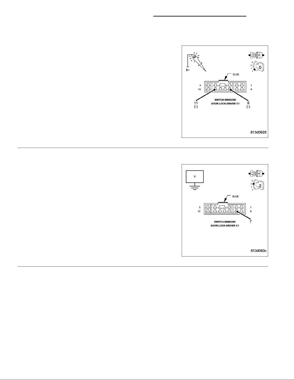
Turn the ignition off.
Disconnect the Driver Window/Door Lock Switch C1 connector.
Using a 12-volt test light connected to 12-volts, check both Ground cir-
cuits in the Door Module C1 connector.
Does the test light illuminate brightly in both terminals?
Yes >>
No >>
(G161) DRIVER DOOR LOCK SWITCH MUX OPEN
6.
Turn the ignition on.
Measure the voltage between the (G161) Driver Door Lock Switch
Mux circuit and ground.
Is the voltage above 4.6 volts?
Yes >>
No >>
Go To 6
Repair the (Z421) or (Z941) Ground circuit for an open.
Perform BODY VERIFICATION TEST - VER 1. (Refer to 8
- ELECTRICAL/ELECTRONIC CONTROL MODULES/
FRONT CONTROL MODULE - DIAGNOSIS AND TESTING)
Replace the Driver Window/Door Lock Switch.
Perform BODY VERIFICATION TEST - VER 1. (Refer to 8
- ELECTRICAL/ELECTRONIC CONTROL MODULES/
FRONT CONTROL MODULE - DIAGNOSIS AND TESTING)
Repair the (G161) Driver Door Lock Switch Mux circuit for
an open.
Perform BODY VERIFICATION TEST - VER 1. (Refer to 8
- ELECTRICAL/ELECTRONIC CONTROL MODULES/
FRONT CONTROL MODULE - DIAGNOSIS AND TESTING)
Page 27

DR/DH POWER LOCKS - ELECTRICAL DIAGNOSTICS 8N - 27
DRIVER DOOR LOCK SWITCH INPUT CIRCUIT SHORTED
Page 28
8N - 28 POWER LOCKS - ELECTRICAL DIAGNOSTICS DR/DH
DRIVER DOOR LOCK SWITCH INPUT CIRCUIT SHORTED (CONTINUED)
For the Power Door Lock circuit diagram (Refer to 8 - ELECTRICAL/POWER LOCKS - SCHEMATICS AND DIAGRAMS).
For a complete wiring diagram Refer to Section 8W.
• When Monitored:
At all times when battery power is supplied to the Instrument Cluster.
• Set Condition:
When the Instrument Cluster senses voltage to the driver door lock switch below .25 volts, the input circuit is
not valid and this code will set.
Possible Causes
(G161) DRIVER DOOR LOCK SWITCH MUX CIRCUIT SHORTED TO GROUND
DOOR LOCK SWITCH SHORTED
INSTRUMENT CLUSTER
Diagnostic Test
DTC PRESENT
1.
Turn the ignition on.
With the DRBIIIT, record and erase DTC’s.
With the DRBIIIT, read DTC’s.
Operate the door locks several times from the Driver
Door Lock Switch while monitoring the DRBIIIT.
Does the DRBIIIT display DRIVER DOOR LOCK
SW INPUT CIRCUIT SHORTED?
Yes >>
No >>
Go To 2
Using the wiring diagram/schematic as a
guide, inspect the wiring and connectors.
Perform BODY VERIFICATION TEST -
VER 1. (Refer to 8 - ELECTRICAL/ELECTRONIC CONTROL MODULES/FRONT
CONTROL MODULE - DIAGNOSIS AND
TESTING)
Page 29
DR/DH POWER LOCKS - ELECTRICAL DIAGNOSTICS 8N - 29
DRIVER DOOR LOCK SWITCH INPUT CIRCUIT SHORTED (CONTINUED)
DOOR LOCK SWITCH SHORTED
2.
Disconnect the Driver Window/Door Lock Switch C1 connector.
With the DRBIIIT in sensors, read the DRV DOOR LOCK SW MUX
circuit.
Is the voltage above 4.6 volts?
Yes >>
No >>
(G161) DRIVER DOOR LOCK SWITCH MUX CIRCUIT SHORTED
3.
Turn the ignition off.
Disconnect the Instrument Cluster C4 connector.
Measure the resistance between the (G161) Driver Door Lock Switch
Mux circuit and ground.
Is the resistance below 1000.0 ohms?
Yes >>
No >>
Replace the Driver Window/Door Lock Switch.
Perform BODY VERIFICATION TEST - VER 1. (Refer to 8
- ELECTRICAL/ELECTRONIC CONTROL MODULES/
FRONT CONTROL MODULE - DIAGNOSIS AND TESTING)
Go To 3
Repair the (G161) Driver Door Lock Switch Mux circuit for
a short to ground.
Perform BODY VERIFICATION TEST - VER 1. (Refer to 8
- ELECTRICAL/ELECTRONIC CONTROL MODULES/
FRONT CONTROL MODULE - DIAGNOSIS AND TESTING)
Replace the Instrument Cluster.
Perform BODY VERIFICATION TEST - VER 1. (Refer to 8
- ELECTRICAL/ELECTRONIC CONTROL MODULES/
FRONT CONTROL MODULE - DIAGNOSIS AND TESTING)
Page 30
8N - 30 POWER LOCKS - ELECTRICAL DIAGNOSTICS DR/DH
DRIVER DOOR LOCK SWITCH INPUT CIRCUIT STUCK
Page 31

DR/DH POWER LOCKS - ELECTRICAL DIAGNOSTICS 8N - 31
DRIVER DOOR LOCK SWITCH INPUT CIRCUIT STUCK (CONTINUED)
For the Power Door Lock circuit diagram (Refer to 8 - ELECTRICAL/POWER LOCKS - SCHEMATICS AND DIAGRAMS).
For a complete wiring diagram Refer to Section 8W.
• When Monitored:
At all times when battery power is supplied to the Instrument Cluster.
• Set Condition:
When the Instrument Cluster senses voltage to the driver door lock switch between 1.3 and 3.75 volts for over
20 seconds, this code will set.
Possible Causes
(G161) DRIVER DOOR LOCK SWITCH MUX CIRCUIT PARTIALLY SHORTED TO GROUND
DOOR LOCK SWITCH SHORTED
INSTRUMENT CLUSTER
Diagnostic Test
DTC PRESENT
1.
Turn the ignition on.
With the DRBIIIT, record and erase DTC’s.
With the DRBIIIT, read DTC’s.
Operate the door locks several times from the Driver
Door Lock Switch while monitoring the DRBIIIT.
Does the DRBIIIT display DRIVER DOOR LOCK
SWITCH INPUT CIRCUIT STUCK?
Yes >>
No >>
Go To 2
Using the wiring diagram/schematic as a
guide, inspect the wiring and connectors.
Operate the switch several times and
check for an occasional sticking problem.
Perform BODY VERIFICATION TEST VER 1. (Refer to 8 - ELECTRICAL/ELECTRONIC CONTROL MODULES/FRONT
CONTROL MODULE - DIAGNOSIS AND
TESTING)
Page 32

8N - 32 POWER LOCKS - ELECTRICAL DIAGNOSTICS DR/DH
DRIVER DOOR LOCK SWITCH INPUT CIRCUIT STUCK (CONTINUED)
DOOR LOCK SWITCH STUCK
2.
Disconnect the Driver Window/Door Lock Switch C1 connector.
With the DRBIIIT in sensors, read the DRV DOOR LOCK SW MUX
circuit.
Is the voltage above 4.6 volts?
Yes >>
No >>
(G161) DRIVER DOOR LOCK SWITCH MUX CIRCUIT SHORTED
3.
Turn the ignition off.
Disconnect the Instrument Cluster C4 connector.
Measure the resistance between the (G161) Driver Door Lock Switch
Mux circuit and ground.
Is the resistance below 10000.0 ohms?
Yes >>
No >>
Replace the Driver Window/Door Lock Switch.
Perform BODY VERIFICATION TEST - VER 1. (Refer to 8
- ELECTRICAL/ELECTRONIC CONTROL MODULES/
FRONT CONTROL MODULE - DIAGNOSIS AND TESTING)
Go To 3
Repair the (G161) Driver Door Lock Switch Mux circuit for
a partial short to ground.
Perform BODY VERIFICATION TEST - VER 1 (Refer to 8
- ELECTRICAL/ELECTRONIC CONTROL MODULES/
FRONT CONTROL MODULE - DIAGNOSIS AND TESTING)
Replace the Instrument Cluster
Perform BODY VERIFICATION TEST - VER 1. (Refer to 8
- ELECTRICAL/ELECTRONIC CONTROL MODULES/
FRONT CONTROL MODULE - DIAGNOSIS AND TESTING)
Page 33

DR/DH POWER LOCKS - ELECTRICAL DIAGNOSTICS 8N - 33
PASSENGER DOOR LOCK SWITCH INPUT CIRCUIT OPEN OR SHORT TO
VOLTAGE
Page 34

8N - 34 POWER LOCKS - ELECTRICAL DIAGNOSTICS DR/DH
PASSENGER DOOR LOCK SWITCH INPUT CIRCUIT OPEN OR SHORT TO VOLTAGE (CONTINUED)
For the Power Door Lock circuit diagram (Refer to 8 - ELECTRICAL/POWER LOCKS - SCHEMATICS AND DIAGRAMS) (Refer to ).
For a complete wiring diagram Refer to Section 8W.
• When Monitored:
At all times when battery power is supplied to the Instrument Cluster.
• Set Condition:
When the Instrument Cluster senses voltage on the passenger door lock switch circuit above 4.85 volts, this
will set and the input will not be valid.
Possible Causes
(G160) PASSENGER DOOR LOCK SWITCH WIRE SHORT TO VOLTAGE
(G160) PASSENGER DOOR LOCK SWITCH MUX CIRCUIT OPEN
(Z461) DOOR LOCK SWITCH GROUND OPEN
DOOR LOCK SWITCH SHORT TO VOLTAGE
DOOR LOCK SWITCH OPEN
INSTRUMENT CLUSTER - VOLTAGE TO HIGH
INSTRUMENT CLUSTER - PASSENGER DOOR LOCK SWITCH VOLTAGE LOW
Diagnostic Test
DTC PRESENT
1.
With the DRBIIIT, record and erase DTC’s.
With the DRBIIIT, read DTC’s.
Operate the door locks from the Passenger Door Lock
Switch while monitoring the DRBIIIT.
Does the DRBIIIT display PASSENGER DOOR
LOCK SWITCH INPUT CIRCUIT OPEN OR SHORT
TO VOLTAGE?
Yes >>
No >>
Go To 2
Using the wiring diagram/schematic as a
guide, inspect the wiring and connectors.
Check for any possible loose connections
at the instrument cluster and the door lock
switch.
Perform BODY VERIFICATION TEST VER 1. (Refer to 8 - ELECTRICAL/ELECTRONIC CONTROL MODULES/FRONT
CONTROL MODULE - DIAGNOSIS AND
TESTING)
Page 35

DR/DH POWER LOCKS - ELECTRICAL DIAGNOSTICS 8N - 35
PASSENGER DOOR LOCK SWITCH INPUT CIRCUIT OPEN OR SHORT TO VOLTAGE (CONTINUED)
INSTRUMENT CLUSTER - PASSENGER DOOR LOCK SWITCH VOLTAGE LOW
2.
With the DRBIIIT in Sensors, read the PASS DOOR LOCK SW voltage.
Voltage reading is:
Above 5.2 volts
Go To 3
Between 4.9 and 5.1 volts
Go To 5
Below 4.8 volts
Replace the Instrument Cluster.
Perform BODY VERIFICATION TEST - VER 1. (Refer to 8 - ELECTRICAL/ELECTRONIC CONTROL
MODULES/FRONT CONTROL MODULE - DIAGNOSIS AND TESTING)
INSTRUMENT CLUSTER - VOLTAGE TO HIGH
3.
Turn ignition off.
Disconnect the Instrument Cluster C4 connector.
Turn ignition on.
Measure the voltage between (G160) Passenger Door Lock Switch
Mux circuit and ground.
Is there any voltage present?
Yes >>
No >>
(G160) PASSENGER DOOR LOCK SWITCH WIRE SHORT TO VOLTAGE
4.
Disconnect the Passenger Door Lock Switch connector.
Measure the voltage between the (G160) Passenger Door Lock Switch
Mux circuit and ground.
Is there any voltage present?
Yes >>
No >>
Go To 4
Replace the Instrument Cluster.
Perform BODY VERIFICATION TEST - VER 1. (Refer to 8
- ELECTRICAL/ELECTRONIC CONTROL MODULES/
FRONT CONTROL MODULE - DIAGNOSIS AND TESTING)
Repair the (G160) Passenger Door Lock Switch Mux circuit for a short to voltage.
Perform BODY VERIFICATION TEST - VER 1. (Refer to 8
- ELECTRICAL/ELECTRONIC CONTROL MODULES/
FRONT CONTROL MODULE - DIAGNOSIS AND TESTING)
Replace the Door Lock Switch.
Perform BODY VERIFICATION TEST - VER 1. (Refer to 8
- ELECTRICAL/ELECTRONIC CONTROL MODULES/
FRONT CONTROL MODULE - DIAGNOSIS AND TESTING)
Page 36

8N - 36 POWER LOCKS - ELECTRICAL DIAGNOSTICS DR/DH
PASSENGER DOOR LOCK SWITCH INPUT CIRCUIT OPEN OR SHORT TO VOLTAGE (CONTINUED)
(Z461) DOOR LOCK SWITCH GROUND OPEN
5.
Turn ignition off.
Disconnect the Passenger Door Lock Switch connector.
Using a 12-volt test light connected to 12-volts, check the (Z461)
Ground circuit in the Door Lock Switch connector.
Does the test light illuminate brightly?
Yes >>
No >>
(G160) PASSENGER DOOR LOCK SWITCH MUX OPEN
6.
Turn ignition on.
Measure the voltage between the (G160) Passenger Door Lock Switch
Mux circuit and ground.
Is the voltage above 4.6 volts?
Yes >>
No >>
Go To 6
Repair the (Z461) Ground circuit for an open.
Perform BODY VERIFICATION TEST - VER 1. (Refer to 8
- ELECTRICAL/ELECTRONIC CONTROL MODULES/
FRONT CONTROL MODULE - DIAGNOSIS AND TESTING)
Replace the Passenger Door Lock Switch.
Perform BODY VERIFICATION TEST - VER 1. (Refer to 8
- ELECTRICAL/ELECTRONIC CONTROL MODULES/
FRONT CONTROL MODULE - DIAGNOSIS AND TESTING)
Repair the (G160) Passenger Door Lock Switch Mux circuit for an open.
Perform BODY VERIFICATION TEST - VER 1. (Refer to 8
- ELECTRICAL/ELECTRONIC CONTROL MODULES/
FRONT CONTROL MODULE - DIAGNOSIS AND TESTING)
Page 37

DR/DH POWER LOCKS - ELECTRICAL DIAGNOSTICS 8N - 37
PASSENGER DOOR LOCK SWITCH INPUT CIRCUIT SHORTED
Page 38

8N - 38 POWER LOCKS - ELECTRICAL DIAGNOSTICS DR/DH
PASSENGER DOOR LOCK SWITCH INPUT CIRCUIT SHORTED (CONTINUED)
For the Power Door Lock circuit diagram (Refer to 8 - ELECTRICAL/POWER LOCKS - SCHEMATICS AND DIAGRAMS).
For a complete wiring diagram Refer to Section 8W.
• When Monitored:
At all times when battery power is supplied to the Instrument Cluster.
• Set Condition:
When the Instrument Cluster senses voltage to the passenger door lock switch below .25 volts, the input circuit
is not valid and this code will set.
Possible Causes
(G160) PASSENGER DOOR LOCK SWITCH MUX CIRCUIT SHORTED TO GROUND
DOOR LOCK SWITCH SHORTED
INSTRUMENT CLUSTER
Diagnostic Test
DTC PRESENT
1.
Turn the ignition on.
With the DRBIIIT, record and erase DTC’s.
With the DRBIIIT, read DTC’s.
Operate the door locks several times from the Driver
Door Lock Switch while monitoring the DRBIIIT.
Does the DRBIIIT display PASSENGER DOOR
LOCK SW INPUT CIRCUIT SHORTED?
Yes >>
No >>
Go To 2
Using the wiring diagram/schematic as a
guide, inspect the wiring and connectors.
Perform BODY VERIFICATION TEST -
VER 1. (Refer to 8 - ELECTRICAL/ELECTRONIC CONTROL MODULES/FRONT
CONTROL MODULE - DIAGNOSIS AND
TESTING)
Page 39

DR/DH POWER LOCKS - ELECTRICAL DIAGNOSTICS 8N - 39
PASSENGER DOOR LOCK SWITCH INPUT CIRCUIT SHORTED (CONTINUED)
DOOR LOCK SWITCH SHORTED
2.
Disconnect the Passenger Door Lock Switch connector.
With the DRBIIIT in sensors, read the PASS DOOR LOCK SW MUX
circuit.
Is the voltage above 4.6 volts?
Yes >>
No >>
(G160) PASSENGER DOOR LOCK SWITCH MUX CIRCUIT SHORTED
3.
Turn the ignition off.
Disconnect the Instrument Cluster C4 connector.
Measure the resistance between the (G160) Passenger Door Lock
Switch Mux circuit and ground.
Is the resistance below 1000.0 ohms?
Yes >>
No >>
Replace the Passenger Door Lock Switch.
Perform BODY VERIFICATION TEST - VER 1. (Refer to 8
- ELECTRICAL/ELECTRONIC CONTROL MODULES/
FRONT CONTROL MODULE - DIAGNOSIS AND TESTING)
Go To 3
Repair the (G160) Passenger Door Lock Switch Mux circuit for a short to ground.
Perform BODY VERIFICATION TEST - VER 1. (Refer to 8
- ELECTRICAL/ELECTRONIC CONTROL MODULES/
FRONT CONTROL MODULE - DIAGNOSIS AND TESTING)
Replace the Instrument Cluster.
Perform BODY VERIFICATION TEST - VER 1. (Refer to 8
- ELECTRICAL/ELECTRONIC CONTROL MODULES/
FRONT CONTROL MODULE - DIAGNOSIS AND TESTING)
Page 40

8N - 40 POWER LOCKS - ELECTRICAL DIAGNOSTICS DR/DH
PASSENGER DOOR LOCK SWITCH INPUT CIRCUIT STUCK
Page 41

DR/DH POWER LOCKS - ELECTRICAL DIAGNOSTICS 8N - 41
PASSENGER DOOR LOCK SWITCH INPUT CIRCUIT STUCK (CONTINUED)
For the Power Door Lock circuit diagram (Refer to 8 - ELECTRICAL/POWER LOCKS - SCHEMATICS AND DIAGRAMS).
For a complete wiring diagram Refer to Section 8W.
• When Monitored:
At all times when battery power is supplied to the Instrument Cluster.
• Set Condition:
When the Instrument Cluster senses voltage to the passenger door lock switch between 1.3 and 3.95 volts for
over 20 seconds, this code will set.
Possible Causes
(G160) PASSENGER DOOR LOCK SWITCH MUX CIRCUIT PARTIALLY SHORTED TO GROUND
DOOR LOCK SWITCH SHORTED
INSTRUMENT CLUSTER
Diagnostic Test
DTC PRESENT
1.
Turn the ignition on.
With the DRBIIIT, record and erase DTC’s.
With the DRBIIIT, read DTC’s.
Operate the door locks several times from the Passen-
ger Door Lock Switch while monitoring the DRBIIIT.
Does the DRBIIIT display PASSENGER DOOR
LOCK SWITCH INPUT CIRCUIT STUCK?
Yes >>
No >>
Go To 2
Using the wiring diagram/schematic as a
guide, inspect the wiring and connectors.
Operate the switch several times and
check for an occasional sticking problem.
Perform BODY VERIFICATION TEST VER 1. (Refer to 8 - ELECTRICAL/ELECTRONIC CONTROL MODULES/FRONT
CONTROL MODULE - DIAGNOSIS AND
TESTING)
Page 42

8N - 42 POWER LOCKS - ELECTRICAL DIAGNOSTICS DR/DH
PASSENGER DOOR LOCK SWITCH INPUT CIRCUIT STUCK (CONTINUED)
DOOR LOCK SWITCH STUCK
2.
Disconnect the Passenger Door Lock Switch connector.
With the DRBIIIT in sensors, read the PASS DOOR LOCK SW MUX
circuit.
Is the voltage above 4.6 volts?
Yes >>
No >>
(G160) PASSENGER DOOR LOCK SWITCH MUX CIRCUIT SHORTED
3.
Turn the ignition off.
Disconnect the Instrument Cluster C4 connector.
Measure the resistance between the (G160) Passenger Door Lock
Switch Mux circuit and ground.
Is the resistance below 10000.0 ohms?
Yes >>
No >>
Replace the Passenger Door Lock Switch.
Perform BODY VERIFICATION TEST - VER 1. (Refer to 8
- ELECTRICAL/ELECTRONIC CONTROL MODULES/
FRONT CONTROL MODULE - DIAGNOSIS AND TESTING)
Go To 3
Repair the (G160) Passenger Door Lock Switch Mux circuit for a partial short to ground.
Perform BODY VERIFICATION TEST - VER 1. (Refer to 8
- ELECTRICAL/ELECTRONIC CONTROL MODULES/
FRONT CONTROL MODULE - DIAGNOSIS AND TESTING)
Replace the Instrument Cluster.
Perform BODY VERIFICATION TEST - VER 1. (Refer to 8
- ELECTRICAL/ELECTRONIC CONTROL MODULES/
FRONT CONTROL MODULE - DIAGNOSIS AND TESTING)
Page 43

DR/DH POWER LOCKS - ELECTRICAL DIAGNOSTICS 8N - 43
RKE FOB BATTERY LOW
For the Power Door Lock circuit diagram. (Refer to 8 - ELECTRICAL/POWER LOCKS - SCHEMATICS AND DIAGRAMS)
For a complete wiring diagram Refer to Section 8W.
• When Monitored:
Upon activation of any button on the Remote Keyless Entry transmitter (fob).
• Set Condition:
The RKE module monitors the input from the fobs and determines if the voltage is within tolerance. If the
battery voltage of the RKE fob falls between 2.0 and 3.5 volts the RKE module will communicates this to the
Instrument Cluster which in turn will set this code.
Possible Causes
BATTERIES LOW
RKE TTRANSMITER - LOW VOLAGE OUTPUT
Diagnosttic Test
CHECK TROUBLE CODE
1.
Turn the ignition on.
Using the RKE transmitter, press the UNLOCK button
six times or more.
With the DRBIIIT, read DTCs.
Does the DRBIIIT display RKE KEY FOB BATTERY LOW?
Yes >>
No >>
BATTERIES LOW
2.
Test the voltage of each battery in the RKE transmitter.
Is the voltage at or above 2.9 in each battery?
Yes >>
No >>
Go To 2
Problem is intermittent and not present at
this time. Check the other transmitters
used with this vehicle to determine which
one set the code. Check the voltage of
each battery in FOB and ensure they
above 2.9 volts each.
Perform BODY VERIFICATION TEST VER 1. (Refer to 8 - ELECTRICAL/ELECTRONIC CONTROL MODULES/FRONT
CONTROL MODULE - DIAGNOSIS AND
TESTING)
Replace the RKE Transmitter.
Perform BODY VERIFICATION TEST - VER 1. (Refer to 8 - ELECTRICAL/ELECTRONIC CONTROL
MODULES/FRONT CONTROL MODULE - DIAGNOSIS AND TESTING)
Replace the batteries and press the unlock button on the transmitter six times to clear the DTC.
Perform BODY VERIFICATION TEST - VER 1. (Refer to 8 - ELECTRICAL/ELECTRONIC CONTROL
MODULES/FRONT CONTROL MODULE - DIAGNOSIS AND TESTING)
Page 44

8N - 44 POWER LOCKS - ELECTRICAL DIAGNOSTICS DR/DH
RKE MODULE COMMUNICATION LINK
For the Power Door Lock circuit diagram. (Refer to 8 - ELECTRICAL/POWER LOCKS - SCHEMATICS AND DIAGRAMS)
For a complete wiring diagram Refer to Section 8W.
• When Monitored:
Whenever battery power is applied the Instrument Cluster.
• Set Condition:
The Instrument Cluster has learned that the vehicle is equipped with Remote Keyless Entry, but then is unable
to communicate with that module, this code will set. The Instrument Cluster provides power for the RKE module and communicates by the PCI bus.
Possible Causes
RKE MODULE OPEN
IJNSTRUMENT CLUSTER
Diagnostic Test
DTC PRESENT
1.
Turn the ignition on.
With the DRBIIIT, record and erase DTC’s.
With the DRBIIIT, read DTC’s.
Operate the door locks several times from the RKE
transmitter while observing the DRBIIIT.
Does the DRBIIIT display RKE MODULE COMM
LINK?
Yes >>
No >>
Go To 2
Using the wiring diagram/schematic as a
guide, inspect the wiring and connectors.
Perform BODY VERIFICATION TEST -
VER 1. (Refer to 8 - ELECTRICAL/ELECTRONIC CONTROL MODULES/FRONT
CONTROL MODULE - DIAGNOSIS AND
TESTING)
Page 45

DR/DH POWER LOCKS - ELECTRICAL DIAGNOSTICS 8N - 45
RKE MODULE COMMUNICATION LINK (CONTINUED)
RKE MODULE OPEN
2.
Turn the ignition off.
Remove the Instrument Cluster.
Replace the RKE module with a known good module.
Connect all Cluster connectors.
With the DRBIIIT, Program the RKE transmitter.
Operate the door locks using the RKE transmitter.
Do the door locks respond correctly with the RKE transmitter?
Yes >>
No >>
Replace the original RKE module.
Perform BODY VERIFICATION TEST - VER 1. (Refer to 8 - ELECTRICAL/ELECTRONIC CONTROL
MODULES/FRONT CONTROL MODULE - DIAGNOSIS AND TESTING)
Replace the Instrument Cluster.
Perform BODY VERIFICATION TEST - VER 1. (Refer to 8 - ELECTRICAL/ELECTRONIC CONTROL
MODULES/FRONT CONTROL MODULE - DIAGNOSIS AND TESTING)
Page 46

8N - 46 POWER LOCKS - ELECTRICAL DIAGNOSTICS DR/DH
*ALL DOOR LOCKS INOPERATIVE
Page 47

DR/DH POWER LOCKS - ELECTRICAL DIAGNOSTICS 8N - 47
*ALL DOOR LOCKS INOPERATIVE (CONTINUED)
For the Power Door Locks circuit diagram (Refer to 8 - ELECTRICAL/POWER LOCKS - SCHEMATICS AND DIAGRAMS).
For a complete wiring diagram Refer to Section 8W.
Possible Causes
DTC PRESENT
FUSE #22 OPEN
(A941) FUSE B+ CIRCUIT OPEN
INSTRUMENT CLUSTER
Diagnostic Test
DTC PRESENT
1.
Turn the ignition on.
With the DRBIIIT, read DTC’s.
Does the DRBIIIT display any Door Lock or Cluster related DTC’s?
Yes >>
No >>
FUSE #22 OPEN
2.
Test both sides of fuse #22 in the PDC.
Is there 12 volts on both sides of fuse #22?
Yes >>
No >>
Refer to the Table of Contents in this section.
Perform BODY VERIFICATION TEST - VER 1. (Refer to 8 - ELECTRICAL/ELECTRONIC CONTROL
MODULES/FRONT CONTROL MODULE - DIAGNOSIS AND TESTING)
Go To 2
Go To 3
Replace the fuse if open and retry the system. If the fuse
blows, locate and repair a short to the Instrument Cluster.
The 12 volt supply to the fuse is a bus bar in the PDC.
Perform BODY VERIFICATION TEST - VER 1. (Refer to 8
- ELECTRICAL/ELECTRONIC CONTROL MODULES/
FRONT CONTROL MODULE - DIAGNOSIS AND TESTING)
Page 48

8N - 48 POWER LOCKS - ELECTRICAL DIAGNOSTICS DR/DH
*ALL DOOR LOCKS INOPERATIVE (CONTINUED)
(A941) FUSED B+ CIRCUIT OPEN
3.
Turn the ignition off.
Remove the instrument cluster.
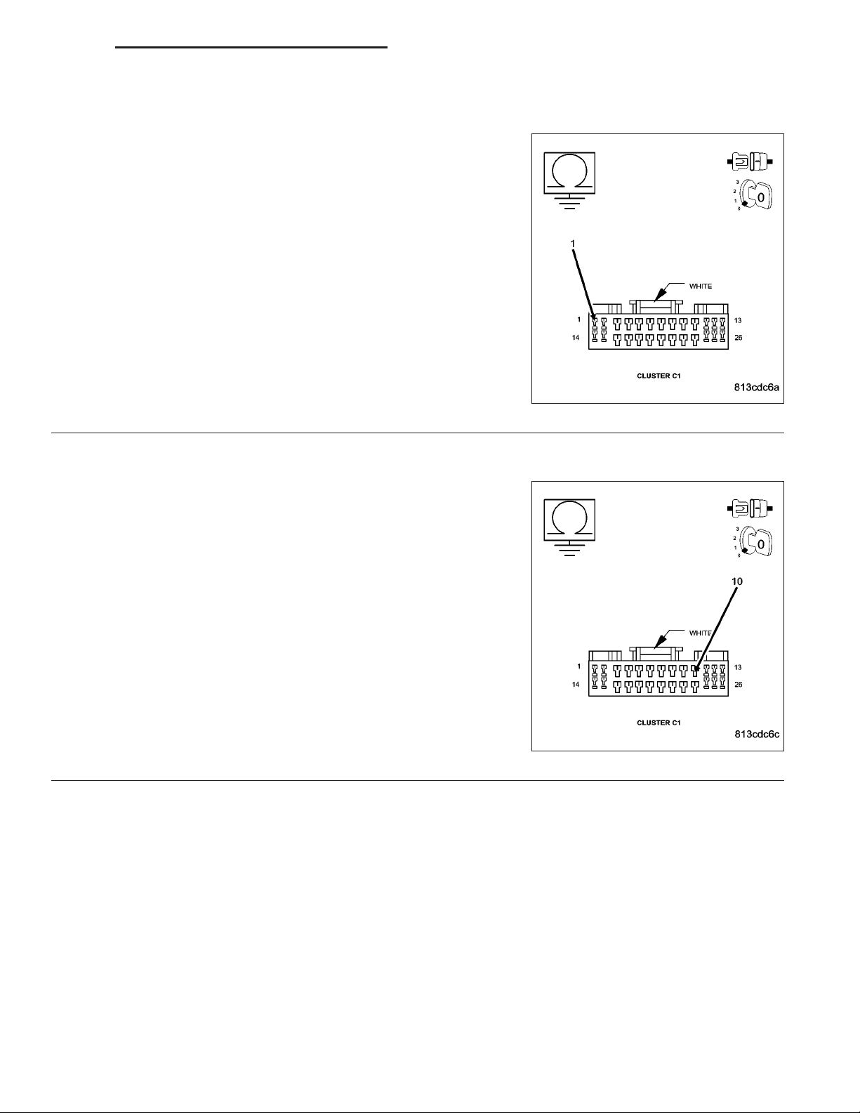
Measure the voltage between the (A941) Fused B+ circuit and ground
(cavity 2 in the C1 connector to ground).
Is the voltage above 10.0 volts on the Fused B+ circuit?
Yes >>
No >>
Replace the Instrument Cluster.
Perform BODY VERIFICATION TEST - VER 1. (Refer to 8
- ELECTRICAL/ELECTRONIC CONTROL MODULES/
FRONT CONTROL MODULE - DIAGNOSIS AND TESTING)
Repair the Fused B+ circuit for an open.
Perform BODY VERIFICATION TEST - VER 1. (Refer to 8
- ELECTRICAL/ELECTRONIC CONTROL MODULES/
FRONT CONTROL MODULE - DIAGNOSIS AND TESTING)
Page 49

DR/DH POWER LOCKS - ELECTRICAL DIAGNOSTICS 8N - 49
*AUTO (ROLLING) DOOR LOCKS INOPERATIVE
For the Power Door Lock circuit diagram (Refer to 8 - ELECTRICAL/POWER LOCKS - SCHEMATICS AND DIAGRAMS).
For a complete wiring diagram Refer to Section 8W.
Possible Causes
DOOR AJAR SWITCH STATUS INCORRECT
TPS OR VSS DTC’s
AUTO DOOR LOCKS NOT ENABLED
INSTRUMENT CLUSTER
Diagnostic Test
CHECK THE DOOR AJAR SWITCH STATUS
1.
Ensure all doors are closed.
With the DRBIII, enter 9Electro/Mech Cluster9 then
9Input/Output9 and observe all of the Door Ajar states.
Does the DRBIII display CLOSED for any door
ajar state?
Yes >>
No >>
ANY TPS OR VSS RELATED DTC’s
2.
With the DRBIII read 9Engine9 and “Anti-Lock Brakes” DTC’s.
Does the DRBIII display any Throttle Position Sensor or Vehicle Speed Sensor related DTC’s?
Yes >>
No >>
Select the appropriate Door Ajar Circuit
Shorted: (Refer to 8 - ELECTRICAL/
LAMPS/LIGHTING - INTERIOR - DIAGNOSIS AND TESTING).
Go To 2
Diagnose and repair the DTC’s. For gas engines (Refer to 9 - ENGINE - ELECTRICAL DIAGNOSTICS).
For diesel engines (Refer to 9 - ENGINE - ELECTRICAL DIAGNOSTICS). For Anti-Lock Brake (Refer to
5 - BRAKES - DIAGNOSIS AND TESTING)
Go To 3
Page 50

8N - 50 POWER LOCKS - ELECTRICAL DIAGNOSTICS DR/DH
*AUTO (ROLLING) DOOR LOCKS INOPERATIVE (CONTINUED)
ENABLE AUTO DOOR LOCKS
3.
With the DRBIII, enter 9Electron/Mech Cluster9 then 9Miscellaneous9 and observe the rolling door lock status.
Does the DRBIII display ROLLING DOOR LOCKS: ENABLED
Yes >>
No >>
Replace the Instrument Cluster.
Perform BODY VERIFICATION TEST - VER 1. (Refer to 8 - ELECTRICAL/ELECTRONIC CONTROL
MODULES/FRONT CONTROL MODULE - DIAGNOSIS AND TESTING)
With the DRBIII, enable the Auto Door Locks.
Perform BODY VERIFICATION TEST - VER 1. (Refer to 8 - ELECTRICAL/ELECTRONIC CONTROL
MODULES/FRONT CONTROL MODULE - DIAGNOSIS AND TESTING)
Page 51

DR/DH POWER LOCKS - ELECTRICAL DIAGNOSTICS 8N - 51
*CYLINDER LOCK SWITCH INOPERATIVE
Page 52

8N - 52 POWER LOCKS - ELECTRICAL DIAGNOSTICS DR/DH
*CYLINDER LOCK SWITCH INOPERATIVE (CONTINUED)
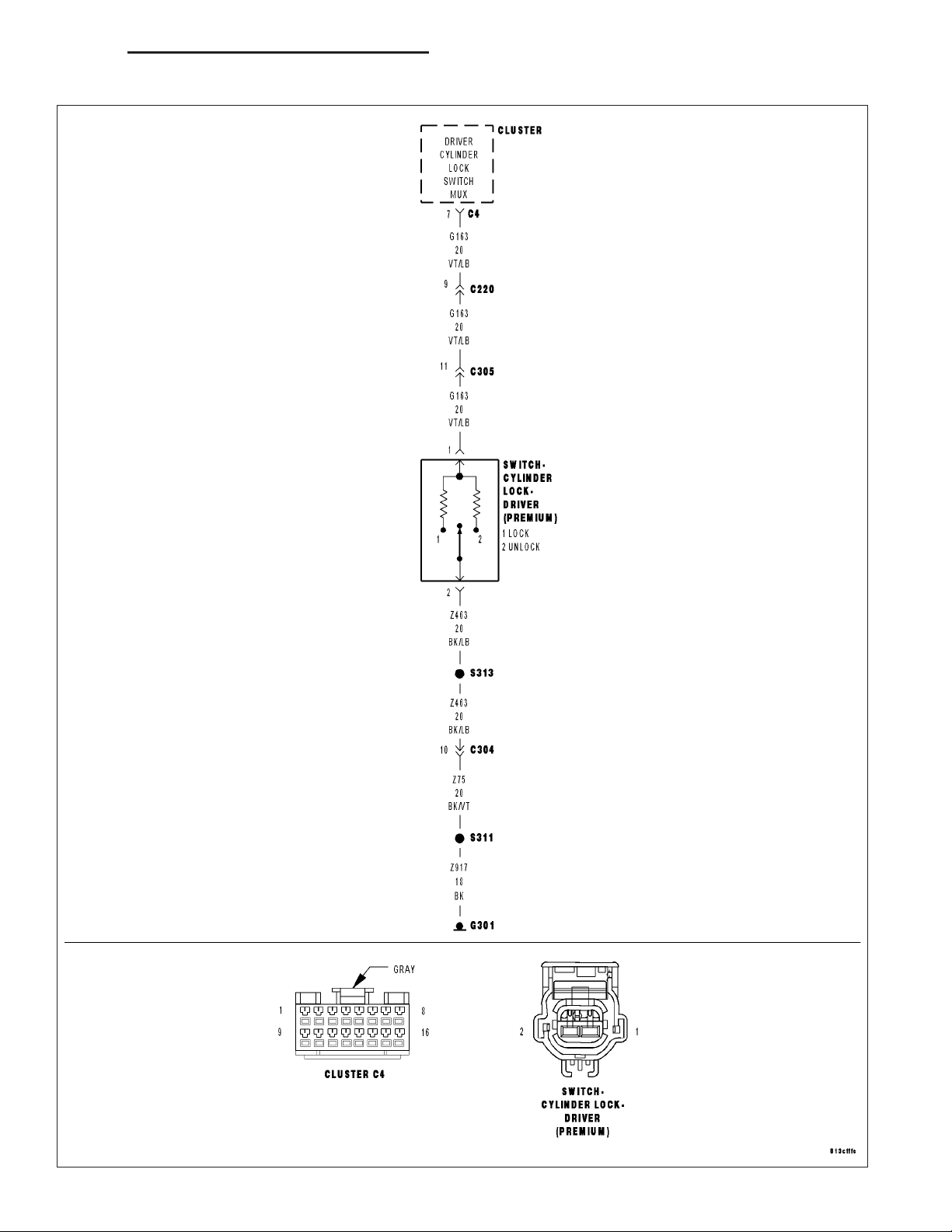
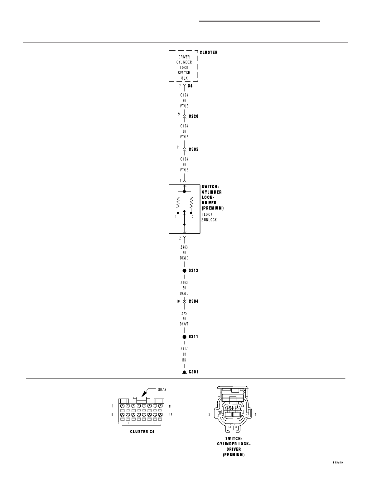
For the Power Door Lock circuit diagram (Refer to 8 - ELECTRICAL/POWER LOCKS - SCHEMATICS AND DIAGRAMS).
For a complete wiring diagram Refer to Section 8W.
Possible Causes
DTC PRESENT
(Z463) CYLINDER LOCK SWITCH GROUND OPEN
(G163) CYLINDER LOCK SWITCH MUX CIRCUIT OPEN
(G163) CYLINDER LOCK SWITCH MUX WIRE SHORT TO GROUND
CYLINDER LOCK SWITCH
INSTRUMENT CLUSTER
Diagnostic Test
DTC PRESENT
1.
Turn the ignition on.
With the DRBIIIT, read DTC’s.
Are there any Power Door Lock related trouble
codes?
Yes >>
No >>
Refer to symptom list for problems related
to Power Door Locks.
Perform BODY VERIFICATION TEST VER 1. (Refer to 8 - ELECTRICAL/ELECTRONIC CONTROL MODULES/FRONT
CONTROL MODULE - DIAGNOSIS AND
TESTING)
Go To 2
Page 53

DR/DH POWER LOCKS - ELECTRICAL DIAGNOSTICS 8N - 53
*CYLINDER LOCK SWITCH INOPERATIVE (CONTINUED)
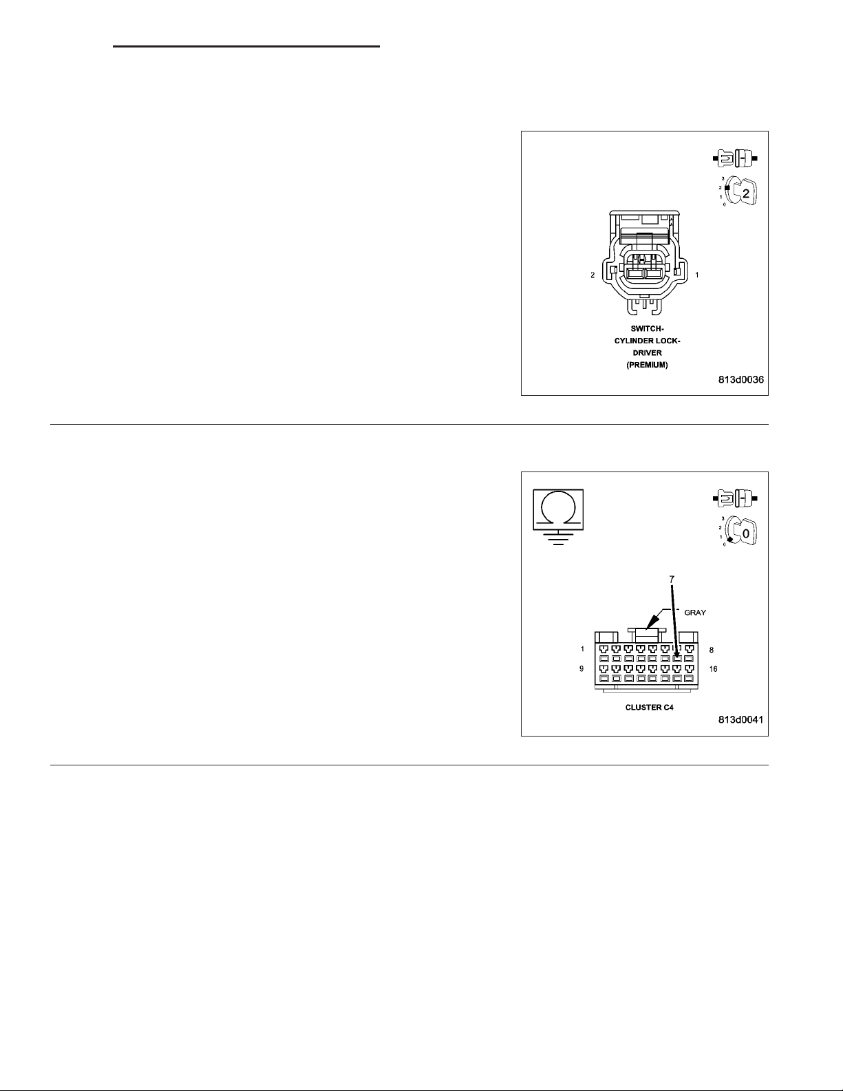
CYLINDER LOCK SWITCH VOLTAGE LOW
2.
Turn the ignition off.
Disconnect the Cylinder Lock Switch connector.
Turn the ignition on.
Measure the voltage between (G163) Cylinder Lock Switch Mux circuit
and ground.
Is the voltage between 4.6 and 5.2 volts?
Yes >>
No >>
(Z463) CYLINDER LOCK SWITCH GROUND OPEN
3.
Using a 12-volt test light connected to 12-volts, check the (Z463)
Ground circuit.
Does the test light illuminate brightly?
Yes >>
No >>
Go To 3
Go To 4
Replace the Cylinder Lock Switch.
Perform BODY VERIFICATION TEST - VER 1. (Refer to 8
- ELECTRICAL/ELECTRONIC CONTROL MODULES/
FRONT CONTROL MODULE - DIAGNOSIS AND TESTING)
Repair the (Z463) Ground circuit for an open.
Perform BODY VERIFICATION TEST - VER 1. (Refer to 8
- ELECTRICAL/ELECTRONIC CONTROL MODULES/
FRONT CONTROL MODULE - DIAGNOSIS AND
TESTING)
Page 54

8N - 54 POWER LOCKS - ELECTRICAL DIAGNOSTICS DR/DH
*CYLINDER LOCK SWITCH INOPERATIVE (CONTINUED)
(G163) CYLINDER LOCK SWITCH MUX OPEN
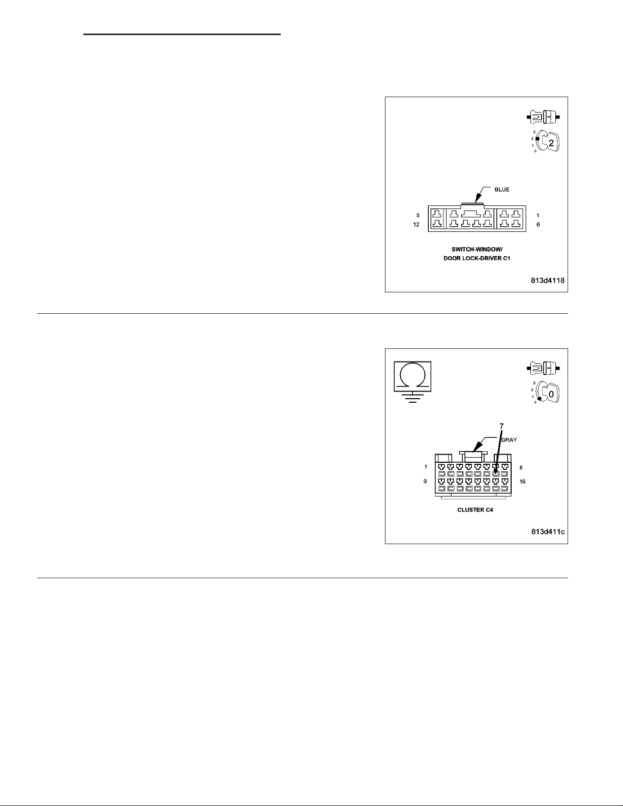
4.
Turn the ignition off.
Disconnect the Instrument Cluster C4 connector.
Measure the resistance of the (G163) Cylinder Lock Switch Mux circuit
between the Switch connector and the Instrument Cluster connector.
Is the resistance below 5.0 ohms?
Yes >>
No >>
(G163) CYLINDER LOCK SWITCH MUX WIRE SHORT TO GROUND
5.
Measure the resistance between Ground and the (G163) Cylinder
Lock Switch Mux circuit in the Cluster C4 connector.
Is the resistance below 1000.0 ohms?
No >>
Yes >>
Go To 5
Repair the (G163) Cylinder Lock Switch Mux circuit for an
open.
Perform BODY VERIFICATION TEST - VER 1. (Refer to 8
- ELECTRICAL/ELECTRONIC CONTROL MODULES/
FRONT CONTROL MODULE - DIAGNOSIS AND TESTING)
Replace the Instrument Cluster.
Perform BODY VERIFICATION TEST - VER 1. (Refer to 8
- ELECTRICAL/ELECTRONIC CONTROL MODULES/
FRONT CONTROL MODULE - DIAGNOSIS AND TESTING)
Repair the (G163) Cylinder Lock Switch Mux circuit for a
short to ground.
Perform BODY VERIFICATION TEST - VER 1. (Refer to 8
- ELECTRICAL/ELECTRONIC CONTROL MODULES/
FRONT CONTROL MODULE - DIAGNOSIS AND TESTING)
Page 55

DR/DH POWER LOCKS - ELECTRICAL DIAGNOSTICS 8N - 55
*DOOR LOCK INHIBIT INOPERATIVE
For a complete wiring diagram Refer to Section 8W.
Possible Causes
CHIME INOPERATIVE
INSTRUMENT CLUSTER
Diagnostic Test
CHIME INOPERATIVE
1.
Turn the ignition off but leave the key in the ignition.
Open the drivers door.
Does the chime sound?
Yes >>
No >>
Replace the Instrument Cluster.Perform BODY VERIFICATION TEST - VER 1. (Refer to 8 - ELECTRICAL/ELECTRONIC CONTROL MODULES/FRONT CONTROL MODULE - DIAGNOSIS AND TESTING)
Perform the test “*KEY IN IGNITION AND DRIVER’S DOOR OPEN CHIME INOPERATIVE”. (Refer to 8
- ELECTRICAL/CHIME/BUZZER - DIAGNOSIS AND TESTING).
Page 56

8N - 56 POWER LOCKS - ELECTRICAL DIAGNOSTICS DR/DH
*LEFT REAR DOOR FAILS TO LOCK AND UNLOCK
Page 57

DR/DH POWER LOCKS - ELECTRICAL DIAGNOSTICS 8N - 57
*LEFT REAR DOOR FAILS TO LOCK AND UNLOCK (CONTINUED)
For the Power Door Lock circuit diagram (Refer to 8 - ELECTRICAL/POWER LOCKS - SCHEMATICS AND DIAGRAMS)
For a complete wiring diagram Refer to Section 8W.
Possible Causes
DTC PRESENT
(P393) DOOR LOCK DRIVER LEFT DOORS WIRE OPEN
(P5) DOOR UNLOCK DRIVER LEFT REAR WIRE OPEN
DOOR LATCH
INSTRUMENT CLUSTER
Diagnostic Test
DTC PRESENT
1.
Turn the ignition on.
With the DRBIIIT, read DTC’s.
Does the DRBIIIT display any Door Lock related
DTC’s?
Yes >>
No >>
Refer to symptom list for problems related
to Power Door Locks to diagnose and
repair DTC’s.
Go To 2
Page 58

8N - 58 POWER LOCKS - ELECTRICAL DIAGNOSTICS DR/DH
*LEFT REAR DOOR FAILS TO LOCK AND UNLOCK (CONTINUED)
INSTRUMENT CLUSTER
2.
Turn the ignition off.
Disconnect the Instrument Cluster C1 connector.
Connect a jumper wire between the (P5) Door Unlock Driver Left Rear
circuit in the Instrument Cluster C1 connector and ground.
Momentarily connect a fused jumper wire between the Fused B+ cir-
cuit and the (P393) Door Lock Driver Left Doors circuit in the Instrument Cluster C1 connector.
Reverse the jumper wires to drive the motor in the opposite direction.
Did the left doors lock and unlock?
Yes >>
No >>
(P393) DOOR LOCK DRIVER LEFT DOORS WIRE OPEN
3.
Disconnect the Left Rear Door Latch connector.
Measure the resistance of the (P393) Door Lock Driver Left Doors cir-
cuit between the Instrument Cluster C1 connector and the Door Latch
connector.
Is the resistance below 5.0 ohms?
Yes >>
No >>
Replace the Instrument Cluster.
Perform BODY VERIFICATION TEST - VER 1. (Refer to 8
- ELECTRICAL/ELECTRONIC CONTROL MODULES/
FRONT CONTROL MODULE - DIAGNOSIS AND TESTING)
Go To 3
Go To 4
Repair the (P393) Door Lock Driver Left Doors wire for an
open.
Perform BODY VERIFICATION TEST - VER 1. (Refer to 8
- ELECTRICAL/ELECTRONIC CONTROL MODULES/
FRONT CONTROL MODULE - DIAGNOSIS AND TESTING)
Page 59

DR/DH POWER LOCKS - ELECTRICAL DIAGNOSTICS 8N - 59
*LEFT REAR DOOR FAILS TO LOCK AND UNLOCK (CONTINUED)
(P5) DOOR UNLOCK DRIVER LEFT REAR WIRE OPEN
4.
Measure the resistance of the (P5) Door Unlock Driver Left Rear circuit between the Instrument Cluster C1 connector and the Door Latch
connector.
Is the resistance below 5.0 ohms?
Yes >>
No >>
Replace the Door Latch.
Perform BODY VERIFICATION TEST - VER 1. (Refer to 8
- ELECTRICAL/ELECTRONIC CONTROL MODULES/
FRONT CONTROL MODULE - DIAGNOSIS AND TESTING)
Repair the (P5) Door Unlock Driver Left Rear wire for an
open.
Perform BODY VERIFICATION TEST - VER 1. (Refer to 8
- ELECTRICAL/ELECTRONIC CONTROL MODULES/
FRONT CONTROL MODULE - DIAGNOSIS AND TESTING)
Page 60

8N - 60 POWER LOCKS - ELECTRICAL DIAGNOSTICS DR/DH
*DRIVER DOOR FAILS TO LOCK AND UNLOCK
Page 61

DR/DH POWER LOCKS - ELECTRICAL DIAGNOSTICS 8N - 61
*DRIVER DOOR FAILS TO LOCK AND UNLOCK (CONTINUED)
For the Power Door Lock circuit diagram (Refer to 8 - ELECTRICAL/POWER LOCKS - SCHEMATICS AND DIAGRAMS)
For a complete wiring diagram Refer to Section 8W.
Possible Causes
DTC PRESENT
(P393) DOOR LOCK DRIVER LEFT DOORS WIRE OPEN
(P1) DOOR UNLOCK DRIVER LEFT FRONT WIRE OPEN
DOOR LATCH
INSTRUMENT CLUSTER
Diagnostic Test
DTC PRESENT
1.
Turn the ignition on.
With the DRBIIIT, read DTC’s.
Does the DRBIIIT display any Door Lock related
DTC’s?
Yes >>
No >>
Refer to symptom list for problems related
to Power Door Locks and diagnose and
repair DTC’s.
Go To 2
Page 62

8N - 62 POWER LOCKS - ELECTRICAL DIAGNOSTICS DR/DH
*DRIVER DOOR FAILS TO LOCK AND UNLOCK (CONTINUED)
INSTRUMENT CLUSTER
2.
Turn the ignition off.
Disconnect the Instrument Cluster C1 connector.
Connect a jumper wire between the (P1) Door Unlock Driver Left Front
circuit in the Instrument Cluster C1 connector and ground.
Momentarily connect a fused jumper wire between the Fused B+ cir-
cuit and the (P393) Door Lock Driver Left Doors circuit in the Instrument Cluster C1 connector.
Reverse the jumper wires to drive the motor in the opposite direction.
Did the Driver Door lock and unlock?
Yes >>
No >>
(P393) DOOR LOCK DRIVER LEFT DOORS WIRE OPEN
3.
Disconnect the Driver Door Latch connector.
Measure the resistance of the (P393) Door Lock Driver Left Doors cir-
cuit between the Instrument Cluster C1 connector and the Door Latch
connector.
Is the resistance below 5.0 ohms?
Yes >>
No >>
Replace the Instrument Cluster.
Perform BODY VERIFICATION TEST - VER 1. (Refer to 8
- ELECTRICAL/ELECTRONIC CONTROL MODULES/
FRONT CONTROL MODULE - DIAGNOSIS AND TESTING)
Go To 3
Go To 4
Repair the (P393) Door Lock Driver Left Doors wire for an
open.
Perform BODY VERIFICATION TEST - VER 1. (Refer to 8
- ELECTRICAL/ELECTRONIC CONTROL MODULES/
FRONT CONTROL MODULE - DIAGNOSIS AND TESTING)
Page 63

DR/DH POWER LOCKS - ELECTRICAL DIAGNOSTICS 8N - 63
*DRIVER DOOR FAILS TO LOCK AND UNLOCK (CONTINUED)
(P1) DOOR UNLOCK DRIVER LEFT FRONT WIRE OPEN
4.
Measure the resistance of the (P1) Door Unlock Driver Left Front circuit between the Instrument Cluster C1 connector and the Door Latch
connector.
Is the resistance below 5.0 ohms?
Yes >>
No >>
Replace the Door Latch.
Perform BODY VERIFICATION TEST - VER 1. (Refer to 8
- ELECTRICAL/ELECTRONIC CONTROL MODULES/
FRONT CONTROL MODULE - DIAGNOSIS AND TESTING)
Repair the (P1) Door Unlock Driver Left Front wire for an
open.
Perform BODY VERIFICATION TEST - VER 1. (Refer to 8
- ELECTRICAL/ELECTRONIC CONTROL MODULES/
FRONT CONTROL MODULE - DIAGNOSIS AND TESTING)
Page 64

8N - 64 POWER LOCKS - ELECTRICAL DIAGNOSTICS DR/DH
*ONE DOOR LOCK MOTOR INOPERATIVE
For the Power Door Lock circuit diagram (Refer to 8 - ELECTRICAL/POWER LOCKS - SCHEMATICS AND DIAGRAMS).
For a complete wiring diagram Refer to Section 8W.
Possible Causes
DTC’s PRESENT
DOOR LOCK DRIVER OR DOOR UNLOCK DRIVER CIRCUIT OPEN
DOOR LATCH
Diagnostic Test
CHECK DOOR LOCK MOTOR CIRCUIT
1.
With the DRBIIIT, read DTCs. If there are any door lock related DTC’s,
refer to symptom list for problems related to Power Door Locks and
diagnose and repair the DTC’s..
Disconnect the inoperative Door Latch connector.
Connect a 12 volt test light between the Door Lock Driver and the
Door Unlock Driver circuits in the latch connector.
NOTE: Graphic shows Passenger Latch – all others similar.
Operate the door locks several time in the lock and unlock positions
from a door lock switch and observe the test light.
Does the test light illuminate brightly when the locks are actuated in both directions?
Yes >>
No >>
Replace the Door latch.
Perform BODY VERIFICATION TEST - VER 1. (Refer to 8
- ELECTRICAL/ELECTRONIC CONTROL MODULES/
FRONT CONTROL MODULE - DIAGNOSIS AND TESTING)
Repair the appropriate Door Lock Driver or Door Unlock Driver circuit for an open.
Perform BODY VERIFICATION TEST - VER 1. (Refer to 8 - ELECTRICAL/ELECTRONIC CONTROL
MODULES/FRONT CONTROL MODULE - DIAGNOSIS AND TESTING)
Page 65

DR/DH POWER LOCKS - ELECTRICAL DIAGNOSTICS 8N - 65
*RIGHT DOORS FAIL TO LOCK AND UNLOCK – QUAD CAB
Page 66

8N - 66 POWER LOCKS - ELECTRICAL DIAGNOSTICS DR/DH
*RIGHT DOORS FAIL TO LOCK AND UNLOCK – QUAD CAB (CONTINUED)
For the Power Door Lock circuit diagram (Refer to 8 - ELECTRICAL/POWER LOCKS - SCHEMATICS AND DIAGRAMS)
For a complete wiring diagram Refer to Section 8W.
Possible Causes
DTC PRESENT
(P392) DOOR LOCK DRIVER RIGHT DOORS WIRE OPEN
(G778) DOOR UNLOCK DRIVER RIGHT DOORS WIRE OPEN
DOOR LATCH
INSTRUMENT CLUSTER
Diagnostic Test
DTC PRESENT
1.
Turn the ignition on.
With the DRBIIIT, read DTC’s.
Does the DRBIIIT display any Door Lock related
DTC’s?
Yes >>
No >>
Refer to symptom list for problems related
to Power Door Locks and diagnose and
repair DTC’s.
Go To 2
Page 67

DR/DH POWER LOCKS - ELECTRICAL DIAGNOSTICS 8N - 67
*RIGHT DOORS FAIL TO LOCK AND UNLOCK – QUAD CAB (CONTINUED)
INSTRUMENT CLUSTER
2.
Turn the ignition off.
Disconnect the Instrument Cluster C1 connector.
Connect a jumper wire between the (G778) Door Unlock Driver Right
Doors circuit in the Instrument Cluster C1 connector and ground.
Momentarily connect a fused jumper wire between the Fused B+ cir-
cuit and the (P392) Door Lock Driver Right Doors circuit in the Instrument Cluster C1 connector.
Reverse the jumper wires to drive the motor in the opposite direction.
Did the Right Doors lock and unlock?
Yes >>
No >>
(P392) DOOR LOCK DRIVER RIGHT DOORS WIRE OPEN
3.
Disconnect the Passenger Door Latch connector.
Measure the resistance of the (P392) Door Lock Driver Right Doors
circuit between the Instrument Cluster C1 connector and the Passenger Door Latch connector.
Is the resistance below 5.0 ohms?
Yes >>
No >>
Replace the Instrument Cluster.
Perform BODY VERIFICATION TEST - VER 1. (Refer to 8
- ELECTRICAL/ELECTRONIC CONTROL MODULES/
FRONT CONTROL MODULE - DIAGNOSIS AND TESTING)
Go To 3
Go To 4
Repair the (P392) Door Lock Driver Right Doors wire for
an open.
Perform BODY VERIFICATION TEST - VER 1. (Refer to 8
- ELECTRICAL/ELECTRONIC CONTROL MODULES/
FRONT CONTROL MODULE - DIAGNOSIS AND TESTING)
Page 68

8N - 68 POWER LOCKS - ELECTRICAL DIAGNOSTICS DR/DH
*RIGHT DOORS FAIL TO LOCK AND UNLOCK – QUAD CAB (CONTINUED)
(G778) DOOR UNLOCK DRIVER RIGHT DOORS WIRE OPEN
4.
Measure the resistance of the (G778) Door Unlock Driver Right Doors
circuit between the Instrument Cluster C1 connector and the Passenger Door Latch connector.
Is the resistance below 5.0 ohms?
Yes >>
No >>
Replace the Door Latch.
Perform BODY VERIFICATION TEST - VER 1. (Refer to 8
- ELECTRICAL/ELECTRONIC CONTROL MODULES/
FRONT CONTROL MODULE - DIAGNOSIS AND TESTING)
Repair the (G778) Door Unlock Driver Right Doors wire for
an open.
Perform BODY VERIFICATION TEST - VER 1. (Refer to 8
- ELECTRICAL/ELECTRONIC CONTROL MODULES/
FRONT CONTROL MODULE - DIAGNOSIS AND TESTING)
Page 69

DR/DH POWER LOCKS - ELECTRICAL DIAGNOSTICS 8N - 69
*RKE INOPERATIVE
For the Power Door Lock circuit diagram (Refer to 8 - ELECTRICAL/POWER LOCKS - SCHEMATICS AND DIAGRAMS).
For a complete wiring diagram Refer to Section 8W.
Possible Causes
DTC PRESENT
TRANSMITTER NOT PROGRAMMED
RKE TRANSMITTER
REMOTE KEYLESS ENTRY MODULE
Diagnostic Test
DTC PRESENT
1.
With the DRBIIIT, read DTCs.
Attempt to operate the door locks with the RKE trans-
mitter.
Does the DRBIIIT display RKE FOB BATTERY
LOW?
Yes >>
No >>
9001 TESTER AVAILABLE
2.
Do you have access to the Miller Special Tool (9001 RF DETECTOR(?
No >>
Yes >>
Refer to symptom RKE FOB BATTERY
LOW in this category.
Go To 2
Go To 3
Go To 5
Page 70

8N - 70 POWER LOCKS - ELECTRICAL DIAGNOSTICS DR/DH
*RKE INOPERATIVE (CONTINUED)
TRANSMITTER NOT PROGRAMMED
3.
Turn the ignition on.
Place transmission in the Park position.
Ensure Vehicle Theft Security System (if equipped) is in Disarmed Mode.
With the DRBIIIT, select ELECTRO/MECH CLUSTER, MISCELLANEOUS, PROGRAM New Fob.
Follow the instructions on the DRBIII screen
Programming mode will last for 30 seconds. To get out of Programming Mode sooner, press PAGE BACK.
Try the door locks using the Transmitter.
Does the RKE System operate properly?
Yes >>
No >>
SUBSTITUTE A KNOWN GOOD TRANSMITTER
4.
Secure a known good transmitter.
With the DRBIIIT, select ELECTRO/MECH CLUSTER, MISCELLANEOUS, PROGRAM New Fob.
Follow the instructions on the DRBIII screen.
Programming mode will last for 30 seconds. To get out of Programming Mode sooner, press PAGE BACK.
Lock and Unlock the vehicle using the transmitter.
Does the RKE System operate properly?
Yes >>
No >>
Repair complete. Check with the customer to see if the other transmitter(s) are operating properly. They
may have to be programmed also.
Perform BODY VERIFICATION TEST - VER 1. (Refer to 8 - ELECTRICAL/ELECTRONIC CONTROL
MODULES/FRONT CONTROL MODULE - DIAGNOSIS AND TESTING)
Go To 4
Replace the original transmitter and program all transmitters that will be used with this vehicle.
Perform BODY VERIFICATION TEST - VER 1. (Refer to 8 - ELECTRICAL/ELECTRONIC CONTROL
MODULES/FRONT CONTROL MODULE - DIAGNOSIS AND TESTING)
Replace the Remote Keyless Entry Module and reprogram all transmitters used with this vehicle.
Perform BODY VERIFICATION TEST - VER 1. (Refer to 8 - ELECTRICAL/ELECTRONIC CONTROL
MODULES/FRONT CONTROL MODULE - DIAGNOSIS AND TESTING)
TEST TRANSMITTER WITH TESTER
5.
Using the 9001 RF Detector, follow the instructions on the back of the tester and test the transmitter several times.
Does the signal strength measure (STRONG(?
Yes >>
No >>
Go To 6
Perform BODY VERIFICATION TEST - VER 1. (Refer to 8 - ELECTRICAL/ELECTRONIC CONTROL
MODULES/FRONT CONTROL MODULE - DIAGNOSIS AND TESTING)
Replace the transmitter and program all transmitters that will be used with this vehicle.
Perform BODY VERIFICATION TEST - VER 1. (Refer to 8 - ELECTRICAL/ELECTRONIC CONTROL
MODULES/FRONT CONTROL MODULE - DIAGNOSIS AND TESTING)
Page 71

DR/DH POWER LOCKS - ELECTRICAL DIAGNOSTICS 8N - 71
*RKE INOPERATIVE (CONTINUED)
PROGRAM RKE TRANSMITTER WITH THE DRBIIIT
6.
Turn the ignition on
Place transmission in the Park position.
Ensure Vehicle Theft Security System (if equipped) is in Disarm Mode.
With the DRBIIIT, select ELECTRO/MECH CLUSTER, MISCELLANEOUS, then PROGRAM New Fob. Follow the
instructions on the screen.
Exit PROGRAM RKE.
Activate the Door Locks using the RKE Transmitter.
NOTE: When repairs are complete, ensure all transmitters used with the vehicle have been programmed.
Did the door locks respond properly to the RKE transmitter commands?
Yes >>
No >>
Repair complete.
Perform BODY VERIFICATION TEST - VER 1. (Refer to 8 - ELECTRICAL/ELECTRONIC CONTROL
MODULES/FRONT CONTROL MODULE - DIAGNOSIS AND TESTING)
Replace the Remote Keyless Entry Module and reprogram all transmitters used with this vehicle.
Perform BODY VERIFICATION TEST - VER 1. (Refer to 8 - ELECTRICAL/ELECTRONIC CONTROL
MODULES/FRONT CONTROL MODULE - DIAGNOSIS AND TESTING)
Page 72

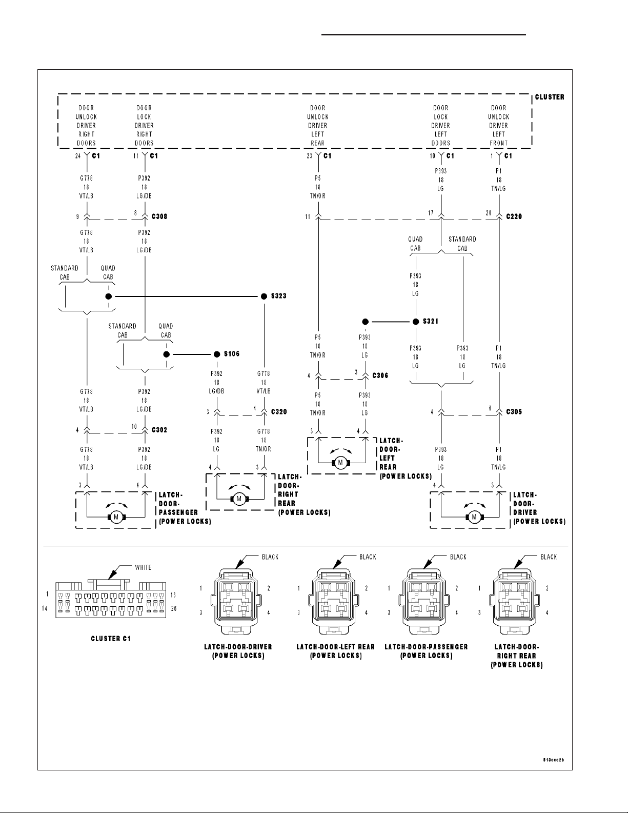
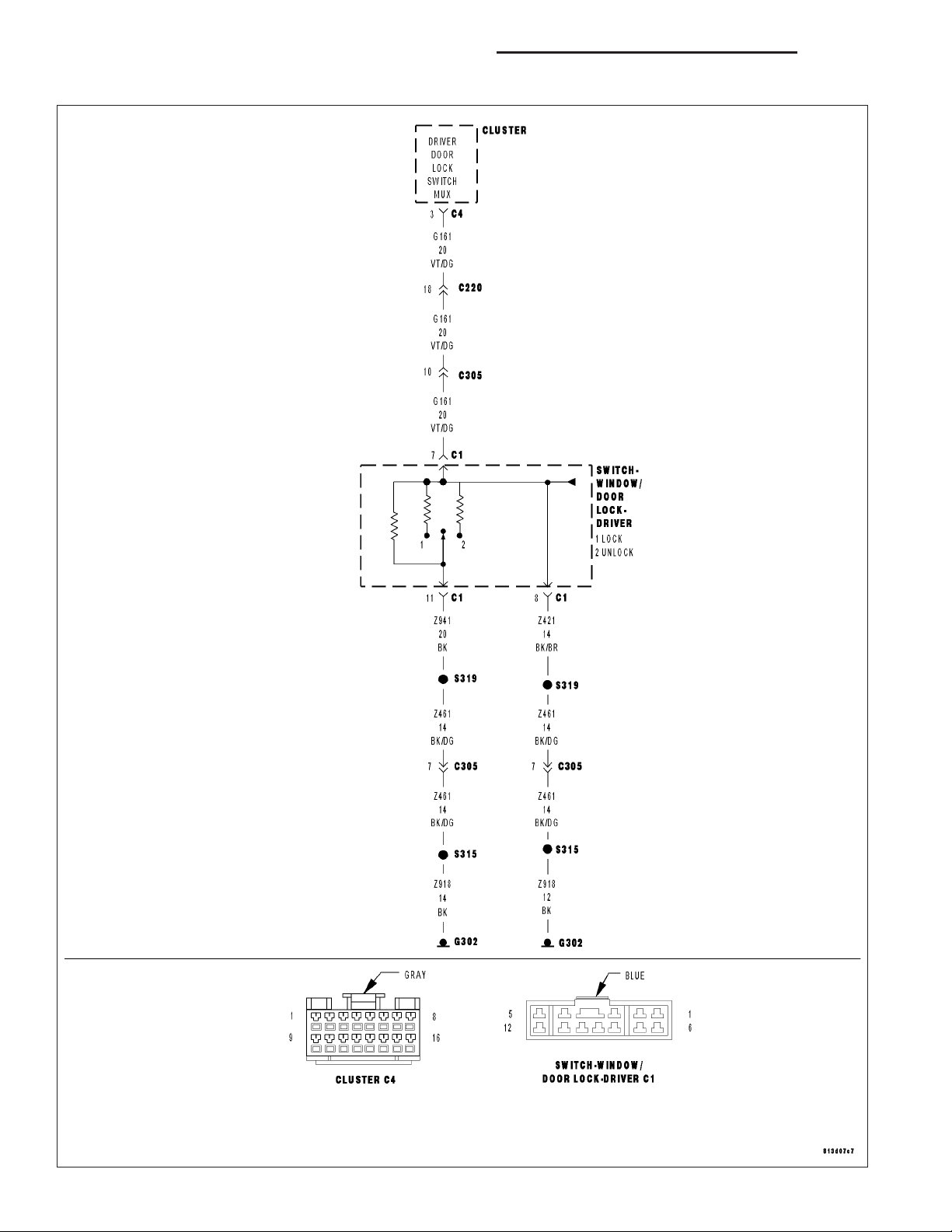
8N - 72 POWER LOCKS - ELECTRICAL DIAGNOSTICS DR/DH
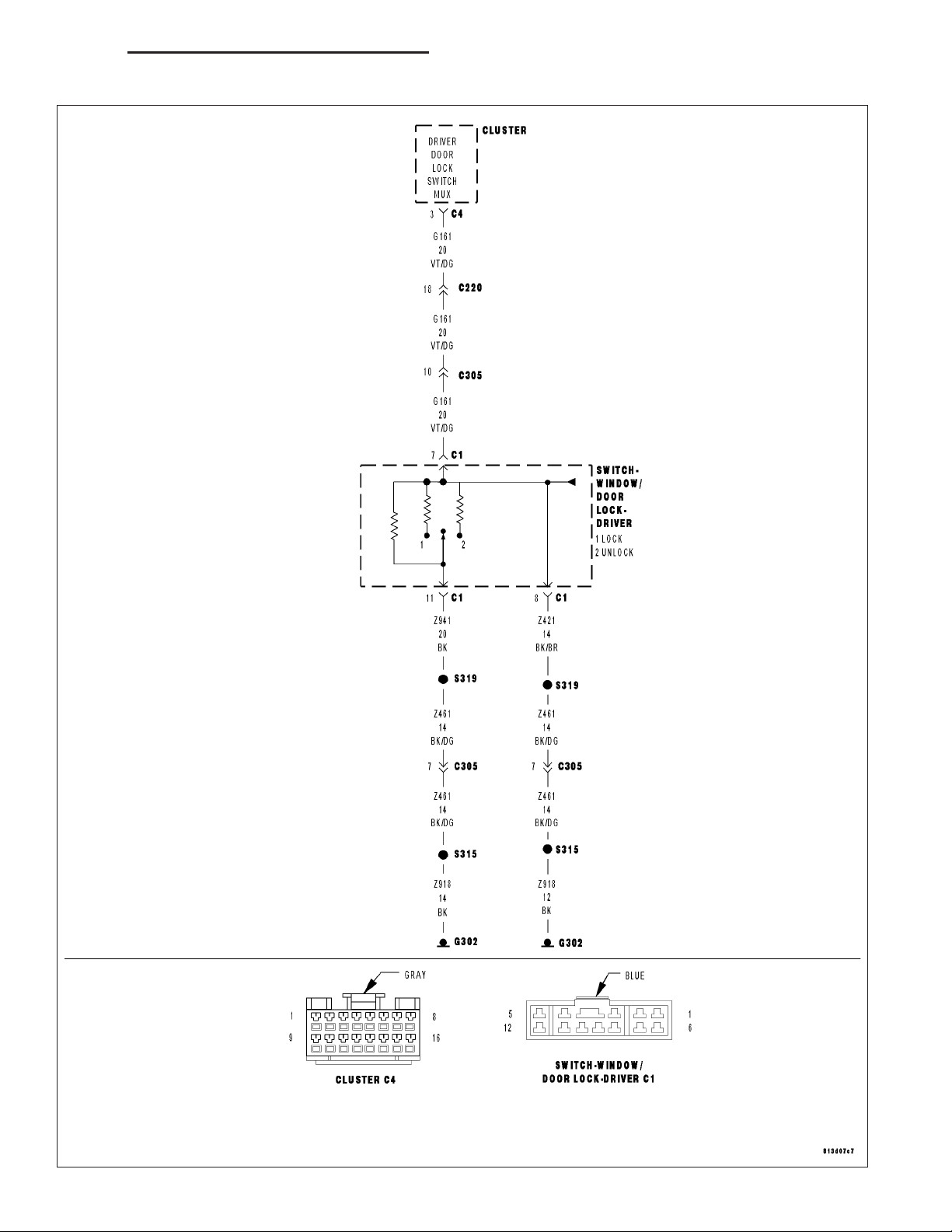
SCHEMATICS AND DIAGRAMS
POWER DOOR LOCK SYSTEM
Page 73

DR/DH POWER LOCKS - SERVICE INFORMATION 8N - 73
POWER LOCKS - SERVICE INFORMATION
TABLE OF CONTENTS
page page
POWER LOCKS - SERVICE INFORMATION
DESCRIPTION .........................73
OPERATION ...........................74
DIAGNOSIS AND TESTING
POWER LOCKS ......................75
MOTOR - DOOR LOCK
DESCRIPTION .........................76
OPERATION ...........................76
DIAGNOSIS AND TESTING
DOOR LOCK MOTOR ..................76
SWITCH - POWER LOCK
DIAGNOSIS AND TESTING
POWER LOCK SWITCH ................77
REMOVAL .............................77
INSTALLATION .........................78
MODULE-REMOTE KEYLESS ENTRY
DESCRIPTION .........................78
OPERATION ...........................78
DIAGNOSIS AND TESTING
REMOTE KEYLESS ENTRY MODULE ......78
REMOVAL .............................79
INSTALLATION .........................79
SWITCH - WINDOW/DOOR LOCK
DESCRIPTION .........................79
OPERATION ...........................80
DIAGNOSIS AND TESTING
WINDOW/LOCK SWITCH ................80
REMOVAL .............................82
INSTALLATION .........................82
TRANSMITTER-REMOTE KEYLESS ENTRY
DIAGNOSIS AND TESTING
REMOTE KEYLESS ENTRY TRANSMITTER . 83
STANDARD PROCEDURE
STANDARD PROCEDURE - RKE
STANDARD PROCEDURE - RKE
STANDARD PROCEDURE - RKE
SPECIFICATIONS
REMOTE KEYLESS ENTRY TRANSMITTER . 85
POWER LOCKS - SERVICE INFORMATION
TRANSMITTER BATTERIES..............83
TRANSMITTER CUSTOMER
PREFERENCES.......................83
TRANSMITTER PROGRAMING ...........84
DESCRIPTION
POWER LOCKS
The power lock system allows all of the doors to be locked or unlocked electrically by operating a switch on either
front door trim panel. The power lock system receives non-switched battery current through a fuse in the Integrated
Power Module (IPM), so that the power locks remain operational, regardless of the ignition switch position.
The instrument cluster locks the doors automatically when the vehicle is driven beyond the speed of 25.7 Km/h (15
mph), all doors are closed and the accelerator pedal is depressed. The rolling door lock feature can be disabled if
desired.
This vehicle also offers several customer programmable features, which allows the selection of several optional
electronic features to suit individual preferences.
The power lock system for this vehicle can also be operated remotely using the available Remote Keyless Entry
(RKE) system radio frequency transmitters, if equipped.
Certain functions and features of the power lock system rely upon resources shared with other electronic modules
in the vehicle over the Programmable Communications Interface (PCI) data bus network. For proper diagnosis of
these electronic modules or of the PCI data bus network, the use of a scan tool and the appropriate diagnostic
information are required.
CENTRAL LOCKING/UNLOCKING
The instrument cluster will lock all doors when a cylinder lock switch is activated in the “lock” position. When the
instrument cluster receives an unlock command from one of the cylinder lock switches, it will unlock only that door.
If the instrument cluster receives a second command within a 5 second period, it will unlock all the remaining doors.
The illuminated entry will activate during door unlock.
Page 74

8N - 74 POWER LOCKS - SERVICE INFORMATION DR/DH
ENHANCED ACCIDENT RESPONSE
Upon detection of an airbag deployment by way of the PCI bus, the instrument cluster will:
• Immediately disable the power door lock output.
• Unlock all doors by activating the door unlock output for approximately 300 milliseconds.
• After actuating the door unlock output, allow the door lock motors to be activated if the door lock input has
been inactive (not erratic) for 2 seconds since the reception of the airbag deployment message.
REMOTE KEYLESS ENTRY
A Radio Frequency (RF) type Remote Keyless Entry (RKE) system is an available factory-installed option on this
model. The RKE system allows the use of a remote battery-powered radio transmitter to signal the instrument cluster to actuate the power lock system. The RKE receiver operates on non-switched battery current through a fuse in
the Integrated Power Module (IPM), so that the system remains operational, regardless of the ignition switch position.
The RKE transmitters are also equipped with a Panic button. If the Panic button on the RKE transmitter is
depressed, the horn will sound and the exterior lights will flash on the vehicle for about three minutes, or until the
Panic button is depressed a second time. A vehicle speed of about 25.7 kilometers-per-hour (15 miles-per-hour) will
also cancel the panic event.
The RKE system can also perform other functions on this vehicle. If the vehicle is equipped with the optional Vehicle
Theft Security System (VTSS), the RKE transmitter will arm the VTSS when the Lock button is depressed, and
disarm the VTSS when the Unlock button is depressed.
The RKE system includes two transmitters when the vehicle is shipped from the factory, but the system can retain
the vehicle access codes of up to a total of four transmitters. The transmitter codes are retained in the RKE module
memory, even if the battery is disconnected. If an RKE transmitter is faulty or lost, new transmitter vehicle access
codes can be programmed into the system using a scan tool.
This vehicle also offers several customer programmable features, which allows the selection of several optional
electronic features to suit individual preferences. Customer programmable feature options affecting the RKE system
include:
• Remote Unlock Sequence - Allows the option of having only the driver side front door unlock when the RKE
transmitter Unlock button is depressed the first time. The remaining doors unlock when the button is depressed
a second time within 5 seconds of the first unlock press. Another option is having all doors unlock upon the
first depression of the RKE transmitter Unlock button.
• Sound Horn on Lock - Allows the option of having the horn sound a short chirp as an audible verification that
the RKE system received a valid Lock request from the RKE transmitter, or having no audible verification.
• Flash Lights with Lock and Unlock - Allows the option of having the park lamps flash as an optical verifi-
cation that the RKE system received a valid Lock request or Unlock request from the RKE transmitter, or having no optical verification.
• Programming Additional Transmitters - Allows up to a total of four transmitter vehicle access codes to be
stored in the receiver memory.
Certain functions and features of the RKE system rely upon resources shared with other electronic modules in the
vehicle over the Programmable Communications Interface (PCI) data bus network. For diagnosis of these electronic
modules or of the PCI data bus network, the use of a scan tool and the appropriate diagnostic information are
required.
OPERATION
POWER LOCKS
The instrument cluster locks or unlocks the doors when an actuation input signal from a door lock switch or Remote
Keyless Entry (RKE) module is received. The instrument cluster turns on the output drivers and provides a voltage
level to the door lock motor for a specified time. All passenger doors can be locked or unlocked using a mechanical
button mounted on the door trim panel. The drivers door can be locked or unlocked by using the key cylinder.
AUTOMATIC DOOR LOCKS
When the automatic door locks are ENABLED the door locks will lock when the vehicle is moving at about 25.7
Km/h (15 mph), all doors are closed and the accelerator pedal is depressed. This feature can be switched ON or
Page 75

DR/DH POWER LOCKS - SERVICE INFORMATION 8N - 75
OFF as desired. When the system is DISABLED the door locks will operate normally, but will not lock automatically
when the vehicle is rolling. Once the automatic door locks have been actuated, they will not try to lock the doors
again until a door is opened.
DOOR LOCK INHIBIT
If the key is in the ignition, in any position, and either front door is ajar, the doors can not be locked, but the unlock
function still operates. Pressing the RKE lock/unlock button under these conditions will result in a normal lock/unlock
activation.
After the key is removed from the ignition switch, or the doors are closed, the power door locks will operate normally.
DOOR LOCK CIRCUIT PROTECTION
If the door lock switch is actuated continuously for more than five seconds the instrument cluster will turn the output
driver OFF (the instrument cluster would consider the switch stuck). Each lock motor is protected with a Positive
Temperature Coefficient device that prevents motor burn out.
REMOTE KEYLESS ENTRY
• LOCK: Pressing the LOCK button locks all doors, sounds horn (chirp) once if enabled, flashes the park lamps
once if enabled, and arms the Vehicle Theft Security System (VTSS), if enabled. The chirp verifies that the
RKE module has sent a message to the instrument cluster for door lock operation. If a door has not been
closed before pressing the LOCK button, the vehicle may not be secured and the VTSS (if equipped) will not
arm until the door is closed.
• UNLOCK: Pressing the UNLOCK button once will unlock the driver’s door first if enabled, flashes the park
lamps twice if enabled, activates the illuminated entry system, and disarms the Vehicle Theft Security System
(VTSS), if equipped. Pressing the UNLOCK button twice within five seconds will unlock all doors, if driver’s
door first is enabled.
• PANIC: Pressing the PANIC button sounds the horns at half second intervals, flashes the exterior lamps, and
turns ON the interior lamps. The panic alarm will remain on for three minutes, or until the PANIC button is
actuated again or the vehicle speed exceeds 25.7 Km/h (15 mph) will cancel the panic event.
The Remote Keyless Entry Module is capable of retaining the transmitter Vehicle Access Code(s) in its memory
even after vehicle power has been interrupted.
DIAGNOSIS AND TESTING
POWER LOCKS
The most reliable, efficient, and accurate means to diagnose the power lock system requires the use of a
scan tool and the proper Diagnostic Procedures information.
Refer to the appropriate wiring information.
Following are tests that will help to diagnose the hard wired components and circuits of the power lock system.
However, these tests may not prove conclusive in the diagnosis of this system. In order to obtain conclusive testing
of the power lock system, the Programmable Communications Interface (PCI) data bus network and all of the electronic modules that provide inputs to, or receive outputs from the power lock system components must be checked.
The instrument cluster will set Diagnostic Trouble Codes (DTC) for the power lock system.
PRELIMINARY DIAGNOSIS
As a preliminary diagnosis for the power lock system, note the system operation while you actuate both the Lock
and Unlock functions with the power lock switches and with the Remote Keyless Entry (RKE) transmitter. Then,
proceed as follows:
• If the entire power lock system fails to function with either the power lock switches or the RKE transmitter,
check the fused B(+) fuse in the Integrated Power Module (IPM).
• If the power lock system functions with both power lock switches, but not with the RKE transmitter, proceed to
diagnosis of the Remote Keyless Entry (RKE) system. (Refer to 8 - ELECTRICAL/POWER LOCKS/KEYLESS
ENTRY TRANSMITTER - DIAGNOSIS AND TESTING) or (Refer to 8 - ELECTRICAL/POWER LOCKS/REMOTE KEYLESS ENTRY MODULE - DIAGNOSIS AND TESTING).
Page 76

8N - 76 POWER LOCKS - SERVICE INFORMATION DR/DH
• If the power lock system functions with the RKE transmitter, but not with one or both power lock switches,
proceed to diagnosis of the door lock switches. (Refer to 8 - ELECTRICAL/POWER LOCKS/POWER LOCK
SWITCH - DIAGNOSIS AND TESTING).
• If the driver side power lock switch operates only the driver side front door power lock motor, but all other
power lock motors operate with the passenger side power lock switch or the RKE transmitter, use a scan tool
and the appropriate diagnostic information to diagnose the Programmable Communications Interface (PCI)
data bus.
• If only one power lock motor fails to operate with both power lock switches and the RKE transmitter, proceed
to diagnosis of the power lock motor. (Refer to 8 - ELECTRICAL/POWER LOCKS/POWER LOCK MOTOR DIAGNOSIS AND TESTING).
MOTOR - DOOR LOCK
DESCRIPTION
The lock mechanisms are actuated by a reversible electric motor mounted within each door. The power lock motors
are integral to the door latch units.
The power lock motors cannot be adjusted or repaired and, if faulty or damaged, the door latch unit must be
replaced.
OPERATION
The door lock motors are controlled by the instrument cluster. A positive and negative battery connection to the two
motor terminals will cause the motor to move in one direction. Reversing the current will cause the motor to move
in the opposite direction.
DIAGNOSIS AND TESTING
DOOR LOCK MOTOR
The most reliable, efficient, and accurate means to diagnose the power lock system requires the use of a
scan tool and the proper Diagnostic Procedures information.
Refer to the appropriate wiring information.
Page 77

DR/DH POWER LOCKS - SERVICE INFORMATION 8N - 77
SWITCH - POWER LOCK
DIAGNOSIS AND TESTING
POWER LOCK SWITCH
The Light-Emitting Diode (LED) illumination lamp of the power lock switch receives battery current through a fuse in
the Integrated Power Module (IPM) on a fused ignition switch output (run) circuit. The power lock switch on the
driver side front door trim panel is integral to the window/lock switch (Refer to 8 - ELECTRICAL/POWER LOCKS/
DOOR MODULE - DIAGNOSIS AND TESTING). If the power lock switch operates, but the LED is inoperative,
check for battery current at the switch with the ignition switch in the On position. If OK, replace the faulty switch.
Refer to the appropriate wiring information.
1. Disconnect and isolate the battery negative cable. Remove the power lock switch from the door trim panel. Disconnect the door wire harness connector for the power lock switch from the switch connector receptacle.
2. Test the power lock switch resistance. See the Power Lock Switch Test chart to determine if the resistance is
correct for the switch in each switch position. If not OK, replace the faulty power lock switch as required.
POWER LOCK SWITCH TEST TABLE
SWITCH POSITION RESISTANCE BETWEEN
PINS1&5
NEUTRAL 10 KILOHMS ±1%
LOCK 820 OHMS ±5%
UNLOCK 330 OHMS ±5%
REMOVAL
The power lock switch on the driver side front door trim panel is integral to the window/lock switch. (Refer to 8 ELECTRICAL/POWER LOCKS/DOOR MODULE - REMOVAL).
1. Disconnect and isolate the battery negative cable.
2. Remove the door trim panel (Refer to 23 - BODY/DOOR - FRONT/TRIM PANEL - REMOVAL).
Page 78

8N - 78 POWER LOCKS - SERVICE INFORMATION DR/DH
3. Remove the switch from the trim panel bezel.
INSTALLATION
1. Insert switch to trim panel bezel.
2. Install door trim panel (Refer to 23 - BODY/DOOR - FRONT/TRIM PANEL - INSTALLATION).
3. Connect battery negative cable.
MODULE-REMOTE KEYLESS ENTRY
DESCRIPTION
When an RKE lock message is sent to the instrument cluster, the instrument cluster actuates the door locks, the
interior lighting is turned off, the horn chirps (if this feature is enabled), the park lamps flash (if this feature is
enabled) and, if the vehicle is so equipped, the Vehicle Theft Security System (VTSS) is armed. When an RKE
unlock message is sent to the instrument cluster, the instrument cluster actuates the driver side front door (or all
doors if this feature is enabled) unlock, the interior lighting is turned on and, if the vehicle is so equipped, the VTSS
is disarmed.
When an RKE panic message is sent to the instrument cluster, the instrument cluster actuates the driver side front
door (or all doors if this feature is enabled) unlock, the interior lighting is turned on and, if the vehicle is so
equipped, the VTSS is disarmed. The panic message will also cause the exterior lamps (including the headlights) to
flash, and the horn to sound for about three minutes, or until a second panic message is sent to the instrument
cluster. A vehicle speed of about 25.7 kilometers-per-hour (15 miles-per-hour) will also cancel the panic event.
OPERATION
Whenever the vehicle battery power is interrupted, the Remote Keyless Module (RKE) Module will retain all vehicle
access codes in its memory. When replacing or adding a key fob transmitter (maximum of 4) a scan tool is required
to program the RKE Module to accept the new Vehicle Access Code if a customer owned transmitter is not available.
If a functioning transmitter is available, (Refer to 8 - ELECTRICAL/POWER LOCKS/KEYLESS ENTRY TRANSMITTER - STANDARD PROCEDURE)
DIAGNOSIS AND TESTING
REMOTE KEYLESS ENTRY MODULE
The most reliable, efficient, and accurate means to diagnose the power lock system requires the use of a
scan tool and the proper Diagnostic Procedures information.
Refer to the appropriate wiring information.
Page 79

DR/DH POWER LOCKS - SERVICE INFORMATION 8N - 79
REMOVAL
1. Disconnect and isolate the battery negative cable.
2. Remove the instrument cluster (Refer to 8 - ELECTRICAL/INSTRUMENT CLUSTER - REMOVAL).
3. Remove remote keyless entry module (2) from
instrument cluster (1).
INSTALLATION
1. Install remote keyless entry module (2) to instrument cluster (1).
2. Install instrument cluster (Refer to 8 - ELECTRICAL/INSTRUMENT CLUSTER - INSTALLATION).
3. Connect the battery negative cable.
SWITCH - WINDOW/DOOR LOCK
DESCRIPTION
A window/lock switch is used on all models equipped with power locks, power windows, and power mirrors. The
window/lock switch houses the following switches:
• Power Lock Switch - A two-way, momentary, resistor multiplexed switch to control the power lock system.
• Power Mirror Selector Switch - A three-position rocker switch selects the right or left power mirror for adjust-
ment, or turns the power mirror system Off.
• Power Mirror Adjustment Switches - Four momentary, arrowhead shaped, directional switches allow the
driver to adjust the selected power mirror in the Up, Down, Right, or Left directions.
• Power Window Lockout Switch - A two-way, latching, push-button switch allows the vehicle operator to lock
out the power window switches on each passenger door so that the passenger door power windows may be
operated only from the master switches.
• Power Window Switches - A two-way, momentary power window switch for the driver side front door. This
switch also has a second detent in the Down direction and internal circuitry to provide an Auto-Down feature
for the driver side front door power window. In addition to the power window switch for its own door, there are
individual master switches for each passenger door power window.
Page 80

8N - 80 POWER LOCKS - SERVICE INFORMATION DR/DH
The window/lock switch also incorporates several green Light-Emitting Diodes (LEDs) that illuminate the power lock
and power window switch paddles, and the power mirror switch directional buttons to improve switch visibility.
OPERATION
The window/lock switch combines a power lock switch, a driver power window switch with an Auto-down feature,
master switches for each passenger door power window, a power window lockout switch, a power mirror selector
switch, and four power mirror adjustment switches in a single unit.
Power Lock Switch
The power lock switch circuitry is connected in series between ground and the driver door switch mux input of the
instrument cluster. Each power lock switch position (Lock, Unlock, and Neutral) provides a different resistance value
to the instrument cluster input, which allows the instrument cluster to sense the switch position. Based upon the
power lock switch input, the instrument cluster controls the battery and ground feed outputs to the individual power
lock motors to lock or unlock the door latches. The Light-Emitting Diode (LED) in the power lock switch is connected
to battery current through the power window circuit breaker in the Integrated Power Module (IPM) on a fused ignition switch output (run-acc) circuit. The switch will be illuminated whenever the ignition switch is in the On or Accessory positions.
Power Window Switches
The power window switch circuitry is connected to battery current through a circuit breaker in the Integrated Power
Module (IPM) on a fused ignition switch output (run-acc) circuit so that the power windows will operate whenever
the ignition switch is in the On or Accessory positions. Each two-way, momentary master passenger power window
switch provides battery current and ground to the individual power window switches on each passenger door so that
the power window switch controls the battery current and ground feeds to its respective power window motor. The
switch for the driver side front door power window is labeled “Auto” and includes an auto-down feature. When this
switch is depressed to a second momentary detent position and released, the driver door power window is automatically operated through an internal circuit and relay to its fully lowered position. The Auto-down event is cancelled if the switch paddle is depressed a second time in either the Up or Down direction. When the two position
window lockout switch is depressed and latched in the lockout position, the battery current feed to each of the
individual passenger power window switches is interrupted so that the passenger door power windows can only be
operated from the master switches. The window lockout switch also controls the battery current feed for the LED in
each passenger power window switch so that the switch will not be illuminated when it is locked out.
Power Mirror Switches
The power mirror switch circuitry is connected to battery current through a fuse in the IPM on a fused B(+) circuit
so that the power mirrors remain operational regardless of the ignition switch position. A rocker type selector switch
has three positions, one to select the right mirror, one to select the left mirror, and a neutral Off position. After the
right or left mirror is selected, one of four directional buttons is depressed to move the selected mirror Up, Down,
Right or Left. The power mirror switch circuitry controls the battery current and ground feeds to each of the four (two
in each mirror head) power mirror motors. The Light-Emitting Diode (LED) in the power mirror switch is connected
to battery current through the power window circuit breaker in the IPM on a fused ignition switch output (run-acc)
circuit so that the switch directional buttons will be illuminated whenever the ignition switch is in the On or Accessory
positions.
DIAGNOSIS AND TESTING
WINDOW/LOCK SWITCH
The Light-Emitting Diode (LED) illumination lamps for all of the Driver Door Module (DDM) power window, power
lock, and power mirror switches receive battery current through the power window circuit breaker in the Integrated
Power Module (IPM). If all of the LEDs are inoperative in the DDM, be certain to diagnose the power window system before replacing the switch unit. (Refer to 8 - ELECTRICAL/POWER WINDOWS - DIAGNOSIS AND TESTING).
If only one LED in the DDM is inoperative, replace the faulty DDM. If the driver side front door power window operates in a normal manner, but the Auto-Down feature is inoperative, replace the faulty DDM. Refer to the appropriate
wiring information.
1. Disconnect and isolate the battery negative cable. Remove the DDM from the door trim panel. Disconnect the
door wire harness connectors for the DDM from the DDM connector receptacles.
Page 81

DR/DH POWER LOCKS - SERVICE INFORMATION 8N - 81
2. Test the DDM switch continuity. See the Driver Door Module Switch Tests chart to determine if the continuity is
correct for the suspect switches in each switch position. If not OK, replace the faulty DDM as required.
DRIVER DOOR MODULE SWITCH TESTS
POWER LOCK SWITCH
RESISTANCE BETWEEN
SWITCH POSITION
NEUTRAL 10 KILOHMS ± 1%
LOCK 820 OHMS ± 5%
UNLOCK 330 OHMS ± 5%
POWER MIRROR SWITCH
SWITCH POSITION
LEFT MIRROR SELECTED
UP PINS1&3
DOWN PINS2&3
RIGHT PINS2&3
LEFT PINS3&6
RIGHT MIRROR SELECTED
CONNECTOR C-1 PINS
7&11
CONTINUITY BETWEEN
PINS OF CONNECTOR
C-2
Page 82

8N - 82 POWER LOCKS - SERVICE INFORMATION DR/DH
DRIVER DOOR MODULE SWITCH TESTS
UP PINS3&7
DOWN PINS2&3
RIGHT PINS2&3
LEFT PINS3&4
POWER WINDOW SWITCH
SWITCH POSITION CONTINUITY BETWEEN
PINS OF CONNECTOR
C-1
NEUTRAL PINS1&8,PINS2&8,
PINS3&8,PINS4&8,
PINS5&8,PINS6&8,
PINS 8 & 10, PINS 8 &
12
LEFT FRONT UP PINS5&9
LEFT FRONT DOWN PINS9&12
RIGHT FRONT UP PINS3&9
RIGHT FRONT DOWN PINS6&9
LEFT REAR UP PINS4&9
LEFT REAR DOWN PINS9&10
RIGHT REAR UP PINS2&9
RIGHT REAR DOWN PINS1&9
POWER WINDOW LOCKOUT SWITCH
SWITCH POSITION CONTINUITY BETWEEN
OFF (SWITCH BUTTON
RAISED - NOT
DEPRESSED)
PIN 9 OF CONNECTOR
C-1&PIN8OF
CONNECTOR C-2
REMOVAL
1. Disconnect and isolate the battery negative cable.
2. Remove the door trim panel (Refer to 23 - BODY/DOOR - FRONT/TRIM PANEL - REMOVAL).
3. Remove the switch from the trim panel bezel.
INSTALLATION
1. Install switch to trim panel bezel.
2. Install door trim panel (Refer to 23 - BODY/DOOR - FRONT/TRIM PANEL - INSTALLATION).
3. Connect battery negative cable.
Page 83

DR/DH POWER LOCKS - SERVICE INFORMATION 8N - 83
TRANSMITTER-REMOTE KEYLESS ENTRY
DIAGNOSIS AND TESTING
REMOTE KEYLESS ENTRY TRANSMITTER
Using special tool 9001, first test to ensure that the
transmitter is functioning. Typical testing distance is
2.5 centimeters (1 inch) for Asian transmitters and
30.5 centimeters (12 inches) for all others. To test,
position the transmitter as shown. Press any transmitter button, then test each button individually. The tool
will beep if a radio signal strength that lights five or
more LED’s is detected. Repeat this test three times.
If transmitter fails any of the test refer to the Diagnostic Procedures information.
STANDARD PROCEDURE
STANDARD PROCEDURE - RKE TRANSMITTER BATTERIES
NOTE: Do not disturb the metal terminal near the batteries. Avoid touching the new batteries. Skin oils may
cause battery deterioration. If batteries are touched, clean with rubbing alcohol.
The Remote Keyless Entry (RKE) transmitter case snaps open and shut for battery access. To replace the RKE
transmitter batteries:
1. Using a thin coin, gently pry at the notch in the center seam of the RKE transmitter case halves near the key ring
until the two halves unsnap. Be careful not to damage the rubber gasket when separating the case halves.
2. Lift the back half of the transmitter case off of the RKE transmitter.
3. Remove the two batteries from the RKE transmitter.
4. Replace the two batteries with new 3V lithium 2016 cell. Install the batteries with the positive terminal up. Reference the “+ SIDE UP” on the inside of the bottom half of the transmitter case.
5. Align the two RKE transmitter case halves with each other, and squeeze them firmly and evenly together until
they snap back into place. Test transmitter operation.
STANDARD PROCEDURE - RKE TRANSMITTER CUSTOMER PREFERENCES
AUTOMATIC (ROLLING) LOCKS
The rolling locks feature can be toggled ON/OFF by using a scan tool only.
HORN CHIRP DISABLING / ENABLING
The horn chirp can be toggled using a scan or by using the Remote Keyless Entry (RKE) transmitter that is already
programmed to the vehicle.
To DISABLE (cancel) the horn chirp feature:
1. Enter the vehicle and close all doors.
2. Fasten the seat belt (this will cancel the seat belt chime).
3. Turn the ignition to the ON position.
Page 84

8N - 84 POWER LOCKS - SERVICE INFORMATION DR/DH
4. Press and hold the LOCK button for 4 seconds. Within 6 seconds with the LOCK button still depressed, press
the UNLOCK button. When a single chime is heard, release both buttons.
5. Turn the ignition OFF.
6. Turn the ignition ON or wait 60 seconds.
7. Test the horn chirp feature by pressing the LOCK button.
If a chime is not heard, program mode was canceled before the feature could be disabled. If necessary, repeat the
procedure.
To ENABLE the horn chirp feature, repeat the above procedure.
OPTICAL CHIRP (FLASH) DISABLING / ENABLING
The optical chirp can be toggled using a scan tool or by using the Remote Keyless Entry (RKE) transmitter that is
already programmed to the vehicle.
To DISABLE (cancel) the optical chirp feature:
1. Enter the vehicle and close all doors.
2. Fasten the seat belt (this will cancel the seat belt chime).
3. Turn the ignition to the ON position.
4. Press and hold the LOCK button for 4 seconds. Within 6 seconds with the LOCK button still depressed, press
the PANIC button. When a single chime is heard, release both buttons.
5. Turn the ignition OFF.
6. Turn the ignition ON or wait 60 seconds.
7. Test the optical chirp feature by pressing the LOCK button.
If a chime is not heard, program mode was canceled before the feature could be disabled. If necessary, repeat the
procedure.
To ENABLE the optical chirp feature, repeat the above procedure.
UNLOCK SEQUENCE
The unlock sequence can be toggled using a scan tool or by using the Remote Keyless Entry (RKE) transmitter that
is already programmed to the vehicle.
To toggle between Driver door first and Unlock all doors function:
1. Enter the vehicle and close all doors.
2. Fasten the seat belt (this will cancel the seat belt chime).
3. Turn the ignition to the ON position.
4. Press and hold the UNLOCK button for 4 seconds. Within 6 seconds with the UNLOCK button still depressed,
press the LOCK button. When a single chime is heard, release both buttons.
5. Turn the ignition OFF.
6. Turn the ignition ON or wait 60 seconds.
If a chime is not heard, program mode was canceled before the feature could be disabled. If necessary, repeat the
procedure.
To toggle this feature, repeat the above procedure.
STANDARD PROCEDURE - RKE TRANSMITTER PROGRAMING
New Remote Keyless Entry (RKE) transmitters can be programed using the DRB IIIT scan tool and the proper Diagnostic Procedures manual. The DRB IIIT scan tool can provide confirmation that the PCI data bus is functional, and
that all of the electronic modules are sending and receiving the proper messages on the PCI data bus.
The following procedure can be used as long as one programmed transmitter is available:
NOTE: When entering program mode using that programmed fob, ALL currently programmed fobs will be
erased and they will have to be reprogrammed for the vehicle. If program mode is entered and no action is
performed, the previously programmed fobs will continue to function.
1. Enter the vehicle and close all doors.
Page 85

DR/DH POWER LOCKS - SERVICE INFORMATION 8N - 85
2. Fasten the seat belt (this will cancel the seat belt chime). Turn the ignition to the RUN position.
3. Press and hold the UNLOCK button on a programmed transmitter for 4 to 10 seconds. Within the 4 to 10 seconds with the UNLOCK button still depressed, press the PANIC button for one second. When a single chime is
heard, release both buttons.The chime indicates the system is in program mode.
4. Press and release both the LOCK and UNLOCK buttons simultaneously on a fob to be programmed. A single
chime will be heard, this indicates the fob has been recognized.
5. Press and release any button on the same fob. A single chime will be heard, this indicates the fob has been
programmed.
6. Repeat steps 4 and 5 for up to a total of 4 fobs.
7. Turn the ignition OFF.
8. Turn the ignition ON or wait 60 seconds.
The vehicle will remain in program mode for up to 60 seconds from when the original chime (step 3) was heard.
After 60 seconds, all programmed transmitters will function normally.
SPECIFICATIONS
REMOTE KEYLESS ENTRY TRANSMITTER
RANGE
Normal operation range is up to a distance of 3 to 7 meters (10 to 23 ft.) of the vehicle. Range may be better or
worse depending on the environment around the vehicle.
Page 86

8N - 86 POWER MIRRORS - SERVICE INFORMATION DR/DH
POWER MIRRORS - SERVICE INFORMATION
TABLE OF CONTENTS
page page
POWER MIRRORS - SERVICE INFORMATION
DESCRIPTION .........................86
OPERATION ...........................86
DIAGNOSIS AND TESTING
POWER MIRRORS ....................86
MIRROR-AUTOMATIC DAY / NIGHT
DESCRIPTION .........................87
OPERATION ...........................87
DIAGNOSIS AND TESTING
AUTOMATIC DAY / NIGHT MIRROR .......88
SWITCH - POWER MIRROR
DIAGNOSIS AND TESTING
POWER MIRROR SWITCH ..............89
REMOVAL .............................89
POWER MIRRORS - SERVICE INFORMATION
DESCRIPTION
AUTOMATIC DAY/NIGHT MIRROR
The automatic day/night mirror system is able to automatically change the reflectance of the inside rear view mirror
in order to reduce the glare of headlamps approaching the vehicle from the rear. The automatic day/night rear view
mirror receives battery current through a fuse in the Integrated Power Module (IPM) only when the ignition switch is
in the On position.
OUTSIDE REAR VIEW MIRROR
The power operated outside rear view mirrors allow the driver to adjust both outside mirrors electrically from the
driver side front seat position by operating a switch on the driver side front door trim panel. The power mirrors
receive a non-switched battery feed through a fuse in the Integrated Power Module (IPM) so that the system will
remain operational, regardless of the ignition switch position.
OPERATION
AUTOMATIC DAY/NIGHT MIRROR
A switch located on the bottom of the automatic day/night mirror housing allows the vehicle operator to select
whether the automatic dimming feature is operational. When the automatic day/night mirror is turned on, the mirror
switch is lighted by an integral Light-Emitting Diode (LED). The mirror will automatically disable its self-dimming
feature whenever the vehicle is being driven in reverse.
OUTSIDE REAR VIEW MIRROR
The heated mirrors include an electric heating grid behind the mirror glass in each outside mirror, which can clear
the mirror glass of ice, snow, or fog. (Refer to 8 - ELECTRICAL/HEATED MIRRORS - DESCRIPTION) for more
information.
DIAGNOSIS AND TESTING
POWER MIRRORS
WIRING VOLTAGE TEST
The following wiring test determines whether or not voltage is continuous through the body harness to switch.
1. Remove the power mirror switch (Refer to 8 - ELECTRICAL/POWER LOCKS/DOOR MODULE - REMOVAL).
2. Disconnect wire harness connector from back of power mirror switch.
3. Connect the clip end of a 12 volt test light to Pin 5 in the mirror switch harness connector. Touch the test light
probe to Pin 3.
Page 87

DR/DH POWER MIRRORS - SERVICE INFORMATION 8N - 87
If the test light illuminates, the wiring circuit between the battery and switch is OK.
If the lamp does not illuminate, first check fuse in the Integrated Power Module (IPM). If fuse is OK, then check for
a broken wire.
Refer to the appropriate wiring information.
POWER MIRROR MOTOR TEST
If the power mirror switch is receiving proper current
and ground and mirrors do not operate, proceed with
power mirror motor test. Refer to the appropriate wiring information.
1. Remove the power mirror switch (Refer to 8 ELECTRICAL/POWER LOCKS/DOOR MODULE REMOVAL).
2. Disconnect wire harness connector to power mirror
switch.
3. Using two jumper wires:
• Connect one to a 12 volt source
• Connect the other to a good body ground
• Refer to the Mirror Motor Test Chart for proper
wire connections at the switch connector
MIRROR MOTOR TEST CHART
12 VOLTS GROUND MIRROR REACTION
SWITCH CONNECTOR RIGHT LEFT
PIN 1 PIN 2 - UP
PIN 6 PIN 2 - LEFT
PIN 2 PIN 1 - DOWN
PIN 2 PIN 6 - RIGHT
PIN 7 PIN 2 UP PIN 4 PIN 2 LEFT PIN 2 PIN 7 DOWN PIN 2 PIN 4 RIGHT -
4. If results shown in table are not obtained, check for open or shorted circuit. Replace mirror assembly as
necessary.
MIRROR-AUTOMATIC DAY / NIGHT
DESCRIPTION
The automatic day/night mirror uses a thin layer of electrochromic material between two pieces of conductive glass
to make up the face of the mirror. When the mirror switch is in the On position, two photocell sensors are used by
the mirror circuitry to monitor external light levels and adjust the reflectance of the mirror.
OPERATION
The ambient photocell sensor is located on the forward-facing (windshield side) of the rear view mirror housing, and
detects the ambient light levels outside of the vehicle. The headlamp photocell sensor is located inside the rear view
mirror housing behind the mirror glass and faces rearward, to detect the level of the light being received at the rear
window side of the mirror. When the circuitry of the automatic day/night mirror detects that the difference between
the two light levels is too great (the light level received at the rear of the mirror is much higher than that at the front
of the mirror), it begins to darken the mirror.
Page 88

8N - 88 POWER MIRRORS - SERVICE INFORMATION DR/DH
The automatic day/night mirror circuitry also monitors the transmission using an input from the backup lamp circuit.
The mirror circuitry is programmed to automatically disable its self-dimming feature whenever it senses that the
transmission backup lamp circuit is energized.
The automatic day/night mirror is a completely self-contained unit and cannot be repaired. If faulty or damaged, the
entire mirror assembly must be replaced.
DIAGNOSIS AND TESTING
AUTOMATIC DAY / NIGHT MIRROR
For complete circuit diagrams, refer to the appropriate wiring information.
1. Check the fuse in the Integrated Power Module
(IPM). If OK, go to Step 2. If not OK, repair the
shorted circuit or component as required and
replace the faulty fuse.
2. Turn the ignition switch to the On position. Check
for battery voltage at the fuse in the IPM. If OK, go
to Step 3. If not OK, repair the open circuit to the
ignition switch as required.
3. Turn the ignition switch to the Off position. Disconnect and isolate the battery negative cable. Unplug
the wire harness connector from the automatic day/
night mirror. Connect the battery negative cable.
Turn the ignition switch to the On position. Check
for battery voltage at the fused ignition switch output (run/start) circuit cavity of the automatic day/
night mirror wire harness connector. If OK, go to Step 4. If not OK, repair the open circuit to the IPM as required.
4. Turn the ignition switch to the Off position. Disconnect and isolate the battery negative cable. Check for continuity
between the ground circuit cavity of the automatic day/night mirror wire harness connector and a good ground.
There should be continuity. If OK, go to Step 5. If not OK, repair the circuit to ground as required.
5. Connect the battery negative cable. Turn the ignition switch to the On position. Set the parking brake. Place the
transmission gear selector lever in the Reverse position. Check for battery voltage at the backup lamp switch
output circuit cavity of the automatic day/night mirror wire harness connector. If OK, go to Step 6. If not OK,
repair the open circuit as required.
6. Turn the ignition switch to the Off position. Disconnect the battery negative cable. Plug in the automatic day/night
mirror wire harness connector. Connect the battery negative cable. Turn the ignition switch to the On position.
Place the transmission gear selector lever in the Neutral position. Place the mirror switch in the On (the LED in
the mirror switch is lighted) position. Cover the forward facing ambient photocell sensor to keep out any ambient
light.
NOTE: The ambient photocell sensor must be covered completely, so that no light reaches the sensor. Use
a finger pressed tightly against the sensor, or cover the sensor completely with electrical tape.
7. Shine a light into the rearward facing headlamp photocell sensor. The mirror glass should darken. If OK, go to
Step 8. If not OK, replace the faulty automatic day/night mirror unit.
8. With the mirror glass darkened, place the transmission gear selector lever in the Reverse position. The mirror
should return to its normal reflectance. If not OK, replace the faulty automatic day/night mirror unit.
Page 89

DR/DH POWER MIRRORS - SERVICE INFORMATION 8N - 89
SWITCH - POWER MIRROR
DIAGNOSIS AND TESTING
POWER MIRROR SWITCH
The power mirror switch is included with the window/lock switch. (Refer to 8 - ELECTRICAL/POWER LOCKS/DOOR
MODULE - DIAGNOSIS AND TESTING).
REMOVAL
The power mirror switch is included with the window/lock switch. (Refer to 8 - ELECTRICAL/POWER LOCKS/DOOR
MODULE - REMOVAL).
Page 90

8N - 90 POWER SEATS - SERVICE INFORMATION DR/DH
POWER SEATS - SERVICE INFORMATION
TABLE OF CONTENTS
page page
POWER SEATS - SERVICE INFORMATION
DESCRIPTION .........................90
OPERATION ...........................90
DIAGNOSIS AND TESTING
POWER SEAT SYSTEM .................90
POWER SEAT TRACK
DESCRIPTION .........................91
OPERATION ...........................91
DIAGNOSIS AND TESTING
POWER SEAT TRACK ..................92
REMOVAL .............................92
INSTALLATION .........................92
SWITCH-POWER SEAT
DESCRIPTION .........................93
OPERATION ...........................93
DIAGNOSIS AND TESTING
POWER SEAT SWITCH .................94
REMOVAL .............................95
INSTALLATION .........................95
POWER SEATS - SERVICE INFORMATION
DESCRIPTION
The power seat system allows the driver and front seat passenger to electrically adjust their seating positions using
the power seat switches located on the outboard seat cushion side shield of each front seat. The power seat system
allows the seating position to be adjusted forward, rearward, front up, front down, rear up, or rear down. The power
seat system receives battery current through a fuse in the Integrated Power Module, regardless of the ignition
switch position. The power seat system includes the following components:
• Driver Power Seat Switch
• Passenger Power Seat Switch
• Driver Power Seat Track
• Passenger Power Seat Track
Some models equipped with the power seat option also feature a manually operated lumbar support in the seat
back. The lumbar support allows the user to adjust lower seat back pressure to achieve optimum comfort and support in the lower lumbar region of the spinal column. The lumbar support is controlled by a knob on the outboard
side of the seat back assembly.
OPERATION
The power seat system receives battery current through a 50 amp fuse in the Power Distribution Center (PDC) so
that the power seats remain operational, regardless of the ignition switch position.
When a power seat switch is actuated, a battery feed and a ground path are applied through the power seat switch
contacts to the appropriate motor or motors. The motor and drive unit operate to move the seat in the selected
direction until the switch is released, or until the travel limit of the power seat track is reached. When the switch is
moved in the opposite direction, the battery feed and ground path to the motor is reversed through the switch contacts. This causes the motor to run in the opposite direction.
DIAGNOSIS AND TESTING
POWER SEAT SYSTEM
Before any testing of the power seat system is attempted, the battery should be fully-charged and all wire harness
connections and pins checked to ensure proper continuity and grounds. Also ensure that the seat being diagnosed
is not jammed by foreign material. With the dome lamp on, apply the power seat switch in the direction of the
concern. If the dome lamp dims, the seat may be jamming. Check under and behind the seat for binding or obstructions. If the dome lamp does not dim, proceed with testing of the individual components and circuits.
Page 91

DR/DH POWER SEATS - SERVICE INFORMATION 8N - 91
For complete circuit diagrams, refer to the appropriate wiring information. The wiring information includes wiring diagrams, proper wire and connector repair procedures, details of wire harness routing and retention, connector
pin-out information and location views for the various wire harness connectors, splices and grounds.
Operate the power seat switch and move the seat in all directions. The seat should move in each of the selected
directions.
If the power seat adjuster fails to operate in more than one direction, proceed as follows:
1. Inspect the power seat adjuster motors to ensure the electrical connectors are fully seated to the motors. If OK,
go to Step 2. If not OK, connect the electrical connector to the fully seated position.
2. Check the power seat fuse in the integrated power module. If OK, go to Step 3. If not OK, repair the circuit as
necessary and replace the inoperative fuse.
3. Remove the power seat switch from the seat cushion side panel. Check for battery voltage at the fused B(+)
circuit cavity of the power seat switch wire harness connector. If OK, go to Step 4. If not OK, repair the open
circuit to the integrated power module as required.
4. Check for continuity between the ground circuit cavity of the power seat switch wire harness connector and a
good ground. There should be continuity. If OK, go to Step 5. If not OK, repair the open circuit to ground as
required.
5. (Refer to 8 - ELECTRICAL/POWER SEATS/SEAT SWITCH - DIAGNOSIS AND TESTING). If the switch tests
OK, check the wire harness between the power seat switch and the motor. If the circuits check OK, replace the
inoperative power seat adjuster assembly. If the circuits are not OK, repair the wire harness as required.
POWER SEAT TRACK
DESCRIPTION
The eight-way power seat option includes a power
seat track assembly (1) located under each front seat.
The power seat track assembly replaces the standard
manually operated seat tracks. The lower half of the
power seat track is secured at the front with two bolts
to the floor panel seat cross member, and at the rear
with two bolts to the floor panel. Four nuts secure the
bottom of the seat cushion frame to the upper half of
the power seat track unit.
The power seat track assembly cannot be repaired,
and is serviced only as a complete assembly. If any
component in this assembly is inoperative or damaged, the entire power seat track must be replaced.
OPERATION
The power seat track unit includes three reversible electric motors that are secured to the upper half of the track
unit. Each motor moves the seat adjuster through a combination of worm-drive gearboxes and screw-type drive
units.
The front and rear of the seat are operated by two separate vertical adjustment motors. These motors can be operated independently of each other, tilting the entire seat assembly forward or rearward; or, they can be operated in
unison by selecting the proper power seat switch functions, which will raise or lower the entire seat assembly. The
third motor is the horizontal adjustment motor, which moves the seat track in the forward and rearward directions.
Page 92

8N - 92 POWER SEATS - SERVICE INFORMATION DR/DH
DIAGNOSIS AND TESTING
POWER SEAT TRACK
For complete circuit diagrams, refer to the appropriate wiring information. The wiring information includes wir-
ing diagrams, proper wire and connector repair procedures, details of wire harness routing and retention, connector
pin-out information and location views for the various wire harness connectors, splices and grounds.
Operate the power seat switch to move all three seat motors in each direction. The seat should move in each of the
selected directions. If the power seat track fails to operate in only one direction, move the seat track a short distance in the opposite direction and test again to be certain that the track is not at its travel limit. If the power seat
track still fails to operate in only one direction, (Refer to 8 - ELECTRICAL/POWER SEATS/DRIVER SEAT SWITCH
- DIAGNOSIS AND TESTING) for power seat switch diagnosis. If the power seat track fails to operate in more than
one direction, proceed as follows:
1. Check the power seat fuse in the integrated power module. If OK, go to Step 2. If not OK, repair the circuit as
necessary and replace the inoperative fuse.
2. Remove the power seat switch from the seat. Check for battery voltage at the fused B(+) circuit cavity of the
power seat switch wire harness connector. If OK, go to Step 3. If not OK, repair the open circuit to the integrated
power module as required.
3. Check for continuity between the ground circuit cavity of the power seat switch wire harness connector and a
good ground. There should be continuity. If OK, go to Step 4. If not OK, repair the open circuit to ground as
required.
4. Test the power seat switch, (Refer to 8 - ELECTRICAL/POWER SEATS/DRIVER SEAT SWITCH - DIAGNOSIS
AND TESTING). If the switch tests OK, check the wire harness between the power seat switch and the motor for
shorts or opens. If the circuits check OK, replace the inoperative power seat track (adjuster) assembly. If the
circuits are not OK, repair the wire harness as required.
REMOVAL
1. Remove the appropriate seat from the vehicle. (Refer to 23 - BODY/SEATS/SEAT - REMOVAL).
2. Remove the power seat switch from the seat. (Refer to 8 - ELECTRICAL/POWER SEATS/DRIVER SEAT
SWITCH - REMOVAL).
3. Remove four seat track mounting nuts from cushion pan.
4. Disconnect the power seat electrical connectors and remove the seat track from the seat cushion.
5. Remove the necessary components that must be transferred to the replacement seat track (seat belt buckles,
wire harness, etc.).
INSTALLATION
1. Install the necessary components that must be transferred to the replacement seat track (seat belt buckles, wire
harness, etc.).
2. Position the seat track and install the retaining nuts on the seat cushion pan studs. Torque the bolts to 25 N·m.
3. Route and connect the power seat electrical connectors on the seat track and cushion pan.
4. Install the power seat switch on the seat. (Refer to 8 - ELECTRICAL/POWER SEATS/DRIVER SEAT SWITCH INSTALLATION).
5. Install the seat in the vehicle (Refer to 23 - BODY/SEATS/SEAT - INSTALLATION).
6. Connect the battery negative cable.
Page 93

DR/DH POWER SEATS - SERVICE INFORMATION 8N - 93
SWITCH-POWER SEAT
DESCRIPTION
The power seats on this vehicle can be adjusted in
eight different directions, up, down, front up, front
down, rear up, rear down, rearward and forward. The
power seat switch is located on the outboard side of
the seat cushion on the seat cushion side shield.
The individual switches in the power seat switch
assembly cannot be repaired. If one switch is damaged or inoperative, the entire power seat switch
assembly must be replaced.
OPERATION
When a power switch control knob or knobs are actuated, a battery feed and a ground path are applied through the
switch contacts to the power seat track adjuster motor. The selected adjuster motor operates to move the seat track
or recliner through its drive unit in the selected direction until the switch is released, or until the travel limit of the
adjuster is reached. When the switch is moved in the opposite direction, the battery feed and ground path to the
motor are reversed through the switch contacts. This causes the adjuster motor to run in the opposite direction.
No power seat switch should be held applied in any direction after the adjuster has reached its travel limit. The
power seat adjuster motors each contain a self-resetting circuit breaker to protect them from overload. However,
consecutive or frequent resetting of the circuit breaker must not be allowed to continue, or the motor may be
damaged.
Page 94

8N - 94 POWER SEATS - SERVICE INFORMATION DR/DH
DIAGNOSIS AND TESTING
POWER SEAT SWITCH
For complete circuit diagrams, refer to the appropriate wiring information. The wiring information
includes wiring diagrams, proper wire and connector
repair procedures, details of wire harness routing and
retention, connector pin-out information and location
views for the various wire harness connectors, splices
and grounds.
1. Disconnect and isolate the battery negative cable.
2. Remove the power seat switch from the power
seat.
3. Using an ohmmeter to test the continuity of the
power seat switches in each position. Refer to the
POWER SEAT SWITCH TEST TABLE. If OK,
(Refer to 8 - ELECTRICAL/POWER SEATS/
POWER SEAT TRACK - DIAGNOSIS AND TESTING). If not OK, replace the inoperative power seat
switch.
POWER SEAT SWITCH TEST TABLE
SWITCH POSITION CONTINUITY BETWEEN
OFF B-N, B-J, B-M
B-E, B-L, B-K
VERTICAL UP (PASSENGER SEAT) A-J, A-N, B-M, B-E
VERTICAL DOWN(PASSENGER SEAT) A-E, A-M, B-N, B-E
VERTICAL UP (DRIVER SEAT) A-E, A-M, B-N, B-J
VERTICAL DOWN (DRIVER SEAT) A-J, A-N, B-M, B-E
HORIZONTAL FORWARD A-L, B-K
HORIZONTAL REARWARD A-K, B-L
FRONT TILT UP A-M, B-N
FRONT TILT DOWN A-N, B-M
REAR TILT UP A-E, B-J
REAR TILT DOWN A-J, B-E
Page 95

DR/DH POWER SEATS - SERVICE INFORMATION 8N - 95
REMOVAL
1. Disconnect and isolate the battery negative cable.
2. Remove the seat cushion side shield from the seat.
3. Pull the switch bezel or side shield unit (1) out from
the seat far enough to access the switch wire harness connector. Gently pry the locking tabs of the
switch away from the wire harness connector and
carefully unplug the connector from the power seat
switch module (2).
4. Remove the screws (3) that secure the power seat
switch (2) to the side shield unit (1).
INSTALLATION
1. Position the power seat switch (2) on the seat
cushion side shield (1) and install the screws (3).
2. Connect the electrical connector.
3. Install the seat cushion side shield on the seat.
4. Connect the battery negative cable.
Page 96

8N - 96 POWER TOP - SUNROOF - SERVICE INFORMATION DR/DH
POWER TOP - SUNROOF - SERVICE INFORMATION
TABLE OF CONTENTS
page page
POWER TOP - SUNROOF - SERVICE
INFORMATION
DESCRIPTION .........................97
OPERATION ...........................98
DIAGNOSIS AND TESTING
POWER TOP - SUNROOF ...............98
MOTOR-SUNROOF
DIAGNOSIS AND TESTING
MOTOR/MODULE - SUNROOF ..........100
STANDARD PROCEDURE
SUNROOF POSITION CALIBRATION ......101
EXCESSIVE FORCE LIMITATION (EFL)
CALIBRATION .......................101
REMOVAL ............................102
INSTALLATION ........................102
SWITCH - SUNROOF
DESCRIPTION ........................103
OPERATION ..........................103
DIAGNOSIS AND TESTING
SWITCH - POWER SUNROOF ...........103
Page 97

DR/DH POWER TOP - SUNROOF - SERVICE INFORMATION 8N - 97
POWER TOP - SUNROOF - SERVICE INFORMATION
DESCRIPTION
The power sunroof system allows the sunroof to be opened, closed or placed in the vent position electrically by
actuating a switch in the overhead console. The sunroof system receives battery feed through a fuse in the Power
Distribution Center (PDC). The sunroof will operate normally with the key in any position while the Accessory Delay
system is active.
Page 98

8N - 98 POWER TOP - SUNROOF - SERVICE INFORMATION DR/DH
The sunroof glass panel tilts upward at the rear for ventilation and slides rearward under the roof when open. The
panel seals flush with the roof in the closed position to eliminate wind noise. The sunroof includes a manual-sliding
sunshade to cover the deep-tinted glass panel.
In addition to the standard power sunroof operation, this vehicle offers several additional features. There is an
express (one-touch) opening and closing feature as well as Excessive Force Limitation (EFL). The EFL function
detects obstacles trapped between the glass and the vehicle roof during a closing motion. Upon sensing an obstacle
the EFL function will reverse direction of the glass to allow removal of the obstacle.
The main components of the power sunroof system are:
• The motor/module assembly
• The power sunroof glass and frame assembly
• The power sunroof switch
• The manual-sliding sunshade
OPERATION
This vehicle has a vent, tilt and slide power sunroof system with express (one-touch) open and closing feature. The
sunroof system receives constant battery feed through a fuse in the Power Distribution Center (PDC). The sunroof
will operate normally with the key in any position while the Accessory Delay system is active. If the sunroof is moving when the key is turned to the START position (crank engine), all motions stop until the key is released, then the
previously requested sunroof motion will resume. The sunroof will also complete a requested motion if the Accessory Delay system goes inactive while the motion is in progress.
A combination push-button and rocker switch module mounted in the overhead console controls sunroof operation.
The sunroof switch is a rocker design with a push button in the center of the two halves of the rocker. Pressing the
rocker towards the front of the car commands the sunroof closed. Pressing the rocker towards the rear of the car
commands the sunroof open. Pressing the center push button commands the sunroof up into the vent position
(Rear of sunroof glass raises above the vehicle roof with glass still covering the sunroof opening). All switch commands operate with the glass starting in any position. (Refer to 8 - ELECTRICAL/POWER TOP/SWITCH - OPERATION) for additional information.
An electronic control system, integral to the motor/module assembly, provides the express open and close functions.
Pressing the 9open9 or 9close9 end of the rocker switch moves the sunroof glass panel to the full open or full closed
position, respectively. During express closing, anytime an obstacle is detected in the way of the glass, the motor will
stop and reverse travel to avoid pinching an occupant’s finger, ice in the track, etc. This function is called Excessive
Force Limitation (EFL). There are two methods of overriding the EFL function.
1. When three EFL events occur without the glass being allowed to fully close, the next close attempt will only
move while the close switch is continuously actuated. This allows the sunroof to be forced closed if multiple close
attempts fail.
2. If the sunroof close switch is continuously actuated during an EFL event, through the reversal, and during a two
second wait time, then continuing to hold the close switch will cause the roof to move towards close with the EFL
protection disabled. This allows the sunroof to be forced closed if it is known that a reversal will occur.
While in EFL override, the closing motion will cease if the sunroof switch is released at any time.
The motor/module is programmed to learn the speed required to drive the panel based on position and recalibrates
itself as needed. If the sunroof becomes uncalibrated, it will only respond to the vent switch. If the vent switch is
pressed, the glass will move toward vent; if the switch is released, all motion stops. In the event that the sunroof
system becomes uncalibrated perform the sunroof position calibration procedure, (Refer to 8 - ELECTRICAL/
POWER TOP/MOTOR - STANDARD PROCEDURE -SUNROOF POSITION CALIBRATION).
DIAGNOSIS AND TESTING
POWER TOP - SUNROOF
NOTE: If there is no sunroof movement when the “OPEN” or “CLOSED” button are pushed but the sunroof
operates when the “VENT” button is pushed and held the sunroof motor/module is out of calibration. Complete the sunroof position calibration procedure prior to performing any sunroof diagnostics, (Refer to 8 ELECTRICAL/POWER TOP/MOTOR - STANDARD PROCEDURE - SUNROOF POSITION CALIBRATION).
Page 99

DR/DH POWER TOP - SUNROOF - SERVICE INFORMATION 8N - 99
Refer to SUNROOF DIAGNOSIS CHART for possible causes. Before beginning sunroof diagnostics verify that all
other power accessories are in proper operating condition. If not, a common electrical problem may exist.
Check the condition of the circuit protection and inspect all wiring connector pins for proper engagement and continuity. For complete circuit diagrams, refer to the appropriate wiring information. The wiring information includes
wiring diagrams, proper wire and connector repair procedures, details of wire harness routing and retention, connector pin-out information and location views for the various wire harness connectors, splices and grounds.
SUNROOF DIAGNOSIS CHART
SYMPTOM POSSIBLE CAUSE CORRECTION
Sunroof completely
inoperative.
Audible whine when switch
is depressed, sunroof does
not operate.
Audible clicking or
ratcheting when switch is
pressed, sunroof does not
operate.
Sunroof vents and opens,
but does not close.
Inoperative control switch. Perform sunroof switch diagnostics,
(Refer to 8 - ELECTRICAL/POWER
TOP/SWITCH - DIAGNOSIS AND
TESTING).
Inoperative circuit ground between
sunroof motor/module and body
harness.
Inoperative power circuit between
sunroof motor/module, control switch,
and body harness.
Inoperative sunroof motor/module. Replace the sunroof motor/module,
Inoperative sunroof motor/module. Replace the sunroof motor/module,
Binding cable. Repair or replace binding cable as
Broken or worn drive cable. Repair or replace binding cable as
Worn drive motor gear. Replace the sunroof motor/module,
Sunroof glass panel out of adjustment. Perform sunroof glass panel
Broken or disengaged trough guide. Repair trough guide as necessary.
Binding cable. Repair or replace binding cable as
Inoperative sunroof 9CLOSE9 circuit. Check the condition of the circuit,
Inoperative control switch. Perform sunroof switch diagnostics,
Inoperative sunroof motor/module. Replace the sunroof motor/module,
Inspect ground connections and
wiring. Repair as necessary.
Check the condition of the circuit
protection and inspect all wiring.
Repair as necessary.
(Refer to 8 - ELECTRICAL/POWER
TOP/MOTOR - REMOVAL).
(Refer to 8 - ELECTRICAL/POWER
TOP/MOTOR - REMOVAL).
necessary.
necessary.
(Refer to 8 - ELECTRICAL/POWER
TOP/MOTOR - REMOVAL).
adjustment procedure, (Refer to 23 BODY/SUNROOF/GLASS PANEL ADJUSTMENTS).
necessary.
connections and wiring. Repair as
necessary.
(Refer to 8 - ELECTRICAL/POWER
TOP/SWITCH - DIAGNOSIS AND
TESTING).
(Refer to 8 - ELECTRICAL/POWER
TOP/MOTOR - REMOVAL).
Page 100

8N - 100 POWER TOP - SUNROOF - SERVICE INFORMATION DR/DH
SYMPTOM POSSIBLE CAUSE CORRECTION
Sunroof vents, but does not
open.
Sunroof does not vent Binding cable or mechanism. Repair or replace binding cable as
Glass movement not
consistent or glass does not
operate smoothly
Binding cable or mechanism. Repair or replace binding cable as
necessary.
Inoperative sunroof 9OPEN9 circuit. Check the condition of the circuit,
connections and wiring. Repair as
necessary.
Inoperative control switch. Perform sunroof switch diagnostics,
(Refer to 8 - ELECTRICAL/POWER
TOP/SWITCH - DIAGNOSIS AND
TESTING).
Inoperative sunroof motor/module. Replace the sunroof motor/module,
(Refer to 8 - ELECTRICAL/POWER
TOP/MOTOR - REMOVAL).
necessary.
Inoperative sunroof 9VENT9 circuit. Check the condition of the circuit,
connections and wiring. Repair as
necessary.
Inoperative control switch. Perform sunroof switch diagnostics,
(Refer to 8 - ELECTRICAL/POWER
TOP/SWITCH - DIAGNOSIS AND
TESTING).
Inoperative sunroof motor/module. Replace the sunroof motor/module,
(Refer to 8 - ELECTRICAL/POWER
TOP/MOTOR - REMOVAL).
Sunroof glass panel out of adjustment. Perform sunroof glass panel
adjustment procedure, (Refer to 23 BODY/SUNROOF/GLASS PANEL ADJUSTMENTS).
MOTOR-SUNROOF
DIAGNOSIS AND TESTING
MOTOR/MODULE - SUNROOF
NOTE: If there is no sunroof movement when the “OPEN” or “CLOSED” button are pushed but the sunroof
operates when the “VENT” button is pushed and held the sunroof motor/module is out of calibration. Complete the sunroof position calibration procedure prior to performing any sunroof diagnostics, (Refer to 8 ELECTRICAL/POWER TOP/MOTOR - STANDARD PROCEDURE - SUNROOF POSITION CALIBRATION).
The wire harness connectors for the sunroof motor/module are located above the vehicle headliner. Removal of the
headliner may be necessary for access to the connector and proper diagnosis of the motor/module, (Refer to 23 BODY/INTERIOR/HEADLINER - REMOVAL). For complete circuit diagrams, refer to the appropriate wiring
information. The wiring information includes wiring diagrams, proper wire and connector repair procedures, details
of wire harness routing and retention, connector pin-out information and location views for the various wire harness
connectors, splices and grounds.
1. Verify that all other power accessories are in proper operating condition. If not, a common electrical problem may
exist.
2. Disconnect the sunroof motor/module. Connect a test light between the harness connector pin 6 and a known
good ground. The test light should illuminate brightly. If OK, go to Step 3. If not OK repair the ground circuit as
necessary.
3. Connect a test light between the harness connector pin 8 and a known good ground. The test light should illuminate brightly. If OK, go to Step 4. If not OK repair the B+ circuit as necessary.
 Loading...