

Page 1

DR POWER SYSTEMS 8N - 1
POWER SYSTEMS
TABLE OF CONTENTS
page page
POWER LOCKS............................ 1
POWER MIRRORS ........................ 11
POWER LOCKS
TABLE OF CONTENTS
page page
POWER LOCKS
DESCRIPTION ..........................1
OPERATION ............................2
DIAGNOSIS AND TESTING - POWER LOCKS . . 3
POWER LOCK SWITCH
DIAGNOSIS AND TESTING - POWER LOCK
SWITCH .............................4
REMOVAL .............................4
INSTALLATION ..........................4
DOOR LOCK MOTOR
DESCRIPTION ..........................5
OPERATION ............................5
DIAGNOSIS AND TESTING - DOOR LOCK
MOTOR ..............................5
DRIVER DOOR MODULE
DESCRIPTION ..........................5
OPERATION ............................5
DIAGNOSIS AND TESTING - DRIVER DOOR
MODULE .............................6
REMOVAL .............................7
INSTALLATION ..........................7
POWER SEATS ........................... 14
POWER WINDOWS........................ 21
REMOTE KEYLESS ENTRY MODULE
DESCRIPTION ..........................7
OPERATION ............................8
DIAGNOSIS AND TESTING - REMOTE
KEYLESS ENTRY MODULE ...............8
REMOVAL .............................8
INSTALLATION ..........................8
REMOTE KEYLESS ENTRY TRANSMITTER
DIAGNOSIS AND TESTING - REMOTE
KEYLESS ENTRY TRANSMITTER ..........8
STANDARD PROCEDURE
STANDARD PROCEDURE - RKE
TRANSMITTER BATTERIES ..............9
STANDARD PROCEDURE - RKE
TRANSMITTER CUSTOMER
PREFERENCES .......................9
STANDARD PROCEDURE - RKE
TRANSMITTER PROGRAMING ...........10
SPECIFICATIONS - REMOTE KEYLESS
ENTRY TRANSMITTER .................10
POWER LOCKS
DESCRIPTION
POWER LOCKS
A power operated door lock system is available factory-installed equipment on this model. The power
lock system allows all of the doors to be locked or
unlocked electrically by operating a switch on either
front door trim panel. The power lock system receives
non-switched battery current through a fuse in the
Integrated Power Module (IPM), so that the power
locks remain operational, regardless of the ignition
switch position.
The instrument cluster locks the doors automati-
cally when the vehicle is driven beyond the speed of
25.7 Km/h (15 mph), all doors are closed and the
accelerator pedal is depressed. The rolling door lock
feature can be disabled if desired.
This vehicle also offers several customer programmable features, which allows the selection of several
optional electronic features to suit individual preferences.
The power lock system for this vehicle can also be
operated remotely using the available Remote Key-
Page 2

8N - 2 POWER LOCKS DR
POWER LOCKS (Continued)
less Entry (RKE) system radio frequency transmitters, if equipped.
Certain functions and features of the power lock
system rely upon resources shared with other electronic modules in the vehicle over the Programmable
Communications Interface (PCI) data bus network.
For proper diagnosis of these electronic modules or of
the PCI data bus network, the use of a DRB IIIt
scan tool and the appropriate diagnostic information
are required.
CENTRAL LOCKING/UNLOCKING
The instrument cluster will lock all doors when a
cylinder lock switch is activated in the “lock” position. When the instrument cluster receives an unlock
command from one of the cylinder lock switches, it
will unlock only that door. If the instrument cluster
receives a second command within a 5 second period,
it will unlock all the remaining doors. The illuminated entry will activate during door unlock.
ENHANCED ACCIDENT RESPONSE
Upon detection of an airbag deployment by way of
the PCI bus, the instrument cluster will:
• Immediately disable the power door lock output.
• Unlock all doors by activating the door unlock
output for approximately 300 milliseconds.
• After actuating the door unlock output, allow
the door lock motors to be activated if the door lock
input has been inactive (not erratic) for 2 seconds
since the reception of the airbag deployment message.
REMOTE KEYLESS ENTRY
A Radio Frequency (RF) type Remote Keyless
Entry (RKE) system is an available factory-installed
option on this model. The RKE system allows the use
of a remote battery-powered radio transmitter to signal the instrument cluster to actuate the power lock
system. The RKE receiver operates on non-switched
battery current through a fuse in the Integrated
Power Module (IPM), so that the system remains
operational, regardless of the ignition switch position.
The RKE transmitters are also equipped with a
Panic button. If the Panic button on the RKE transmitter is depressed, the horn will sound and the
exterior lights will flash on the vehicle for about
three minutes, or until the Panic button is depressed
a second time. A vehicle speed of about 25.7 kilometers-per-hour (15 miles-per-hour) will also cancel the
panic event.
The RKE system can also perform other functions
on this vehicle. If the vehicle is equipped with the
optional Vehicle Theft Security System (VTSS), the
RKE transmitter will arm the VTSS when the Lock
button is depressed, and disarm the VTSS when the
Unlock button is depressed.
The RKE system includes two transmitters when
the vehicle is shipped from the factory, but the system can retain the vehicle access codes of up to a
total of four transmitters. The transmitter codes are
retained in the RKE module memory, even if the battery is disconnected. If an RKE transmitter is faulty
or lost, new transmitter vehicle access codes can be
programmed into the system using a DRB IIIt scan
tool.
This vehicle also offers several customer programmable features, which allows the selection of several
optional electronic features to suit individual preferences. Customer programmable feature options
affecting the RKE system include:
• Remote Unlock Sequence - Allows the option
of having only the driver side front door unlock when
the RKE transmitter Unlock button is depressed the
first time. The remaining doors unlock when the button is depressed a second time within 5 seconds of
the first unlock press. Another option is having all
doors unlock upon the first depression of the RKE
transmitter Unlock button.
• Sound Horn on Lock - Allows the option of
having the horn sound a short chirp as an audible
verification that the RKE system received a valid
Lock request from the RKE transmitter, or having no
audible verification.
• Flash Lights with Lock and Unlock - Allows
the option of having the park lamps flash as an optical verification that the RKE system received a valid
Lock request or Unlock request from the RKE transmitter, or having no optical verification.
• Programming Additional Transmitters -
Allows up to a total of four transmitter vehicle access
codes to be stored in the receiver memory.
Certain functions and features of the RKE system
rely upon resources shared with other electronic
modules in the vehicle over the Programmable Communications Interface (PCI) data bus network. The
PCI data bus network allows the sharing of sensor
information. This helps to reduce wire harness complexity, internal controller hardware, and component
sensor current loads. For diagnosis of these electronic
modules or of the PCI data bus network, the use of a
DRB IIIt scan tool and the appropriate diagnostic
information are required.
OPERATION
POWER LOCKS
The instrument cluster locks or unlocks the doors
when an actuation input signal from a door lock
switch or Remote Keyless Entry Module (RKE) is
received. The instrument cluster turns on the output
Page 3

DR POWER LOCKS 8N - 3
POWER LOCKS (Continued)
drivers and provides a voltage level to the door lock
motor for a specified time. All passenger doors can be
locked or unlocked using a mechanical button
mounted on the door trim panel. The front passenger
doors can be locked or unlocked by using the key cylinder.
AUTOMATIC DOOR LOCKS
When the automatic door locks are ENABLED the
door locks will lock when the vehicle is moving at
about 25.7 Km/h (15 mph), all doors are closed and
the accelerator pedal is depressed. This feature can
be switched ON or OFF as desired. When the system
is DISABLED the door locks will operate normally,
but will not lock automatically when the vehicle is
rolling. Once the automatic door locks have been
actuated, they will not try to lock the doors again
until a door is opened.
DOOR LOCK INHIBIT
If the key is in the ignition, in any position, and
either front door is ajar, the doors can not be locked,
but the unlock function still operates. Pressing the
RKE lock/unlock button under these conditions will
result in a normal lock/unlock activation.
After the key is removed from the ignition switch,
or the doors are closed, the power door locks will
operate normally.
DOOR LOCK CIRCUIT PROTECTION
If the door lock switch is actuated continuously for
more than five seconds the instrument cluster will
turn the output driver OFF (the instrument cluster
would consider the switch stuck). Each lock motor is
protected with a Positive Temperature Coefficient
device that prevents motor burn out.
REMOTE KEYLESS ENTRY
• LOCK: Pressing the LOCK button locks all
doors, sounds horn (chirp) once if enabled, flashes the
park lamps once if enabled, and arms the Vehicle
Theft Security System (VTSS), if enabled. The chirp
verifies that the RKE module has sent a message to
the instrument cluster for door lock operation. If a
door has not been closed before pressing the LOCK
button, the vehicle may not be secured and the VTSS
(if equipped) will not arm until the door is closed.
• UNLOCK: Pressing the UNLOCK button once
will unlock the driver’s door first if enabled, flashes
the park lamps twice if enabled, activates the illuminated entry system, and disarms the Vehicle Theft
Security System (VTSS), if equipped. Pressing the
UNLOCK button twice within five seconds will
unlock all doors, if driver’s door first is enabled.
• PANIC: Pressing the PANIC button sounds the
horns at half second intervals, flashes the exterior
lamps, and turns ON the interior lamps. The panic
alarm will remain on for three minutes, or until the
PANIC button is actuated again or the vehicle speed
exceeds 25.7 Km/h (15 mph) will cancel the panic
event.
The Remote Keyless Entry Module is capable of
retaining the transmitter Vehicle Access Code(s) in
its memory even after vehicle power has been interrupted.
DIAGNOSIS AND TESTING - POWER LOCKS
The most reliable, efficient, and accurate
means to diagnose the power lock system
requires the use of a DRBIIIt scan tool and the
proper Diagnostic Procedures manual. The
DRBIIIt scan tool can provide confirmation
that the PCI data bus is functional, that all of
the electronic modules are sending and receiving the proper messages on the PCI data bus,
and that the power lock motors are being sent
the proper hard wired outputs by the relays for
them to perform their power lock system functions.
Following are tests that will help to diagnose the
hard wired components and circuits of the power lock
system. However, these tests may not prove conclusive in the diagnosis of this system. In order to
obtain conclusive testing of the power lock system,
the Programmable Communications Interface (PCI)
data bus network and all of the electronic modules
that provide inputs to, or receive outputs from the
power lock system components must be checked.
The instrument cluster will set Diagnostic Trouble
Codes (DTC) for the power lock system.
Refer to the appropriate wiring information. The
wiring information includes wiring diagrams, proper
wire and connector repair procedures, details of wire
harness routing and retention, connector pin-out
information and location views for the various wire
harness connectors, splices and grounds.
PRELIMINARY DIAGNOSIS
As a preliminary diagnosis for the power lock system, note the system operation while you actuate
both the Lock and Unlock functions with the power
lock switches and with the Remote Keyless Entry
(RKE) transmitter. Then, proceed as follows:
• If the entire power lock system fails to function
with either the power lock switches or the RKE
transmitter, check the fused B(+) fuse in the Integrated Power Module (IPM).
• If the power lock system functions with both
power lock switches, but not with the RKE transmitter, proceed to diagnosis of the Remote Keyless Entry
(RKE) system. (Refer to 8 - ELECTRICAL/POWER
LOCKS/KEYLESS ENTRY TRANSMITTER - DIAG-
Page 4
8N - 4 POWER LOCKS DR
POWER LOCKS (Continued)
NOSIS AND TESTING) or (Refer to 8 - ELECTRICAL/POWER LOCKS/REMOTE KEYLESS ENTRY
MODULE - DIAGNOSIS AND TESTING).
• If the power lock system functions with the RKE
transmitter, but not with one or both power lock
switches, proceed to diagnosis of the door lock
switches. (Refer to 8 - ELECTRICAL/POWER
LOCKS/POWER LOCK SWITCH - DIAGNOSIS AND
TESTING).
• If the driver side power lock switch operates
only the driver side front door power lock motor, but
all other power lock motors operate with the passenger side power lock switch or the RKE transmitter,
use a DRBIIIt scan tool and the appropriate diagnostic information to diagnose the Programmable Communications Interface (PCI) data bus.
• If only one power lock motor fails to operate
with both power lock switches and the RKE transmitter, proceed to diagnosis of the power lock motor.
(Refer to 8 - ELECTRICAL/POWER LOCKS/POWER
LOCK MOTOR - DIAGNOSIS AND TESTING).
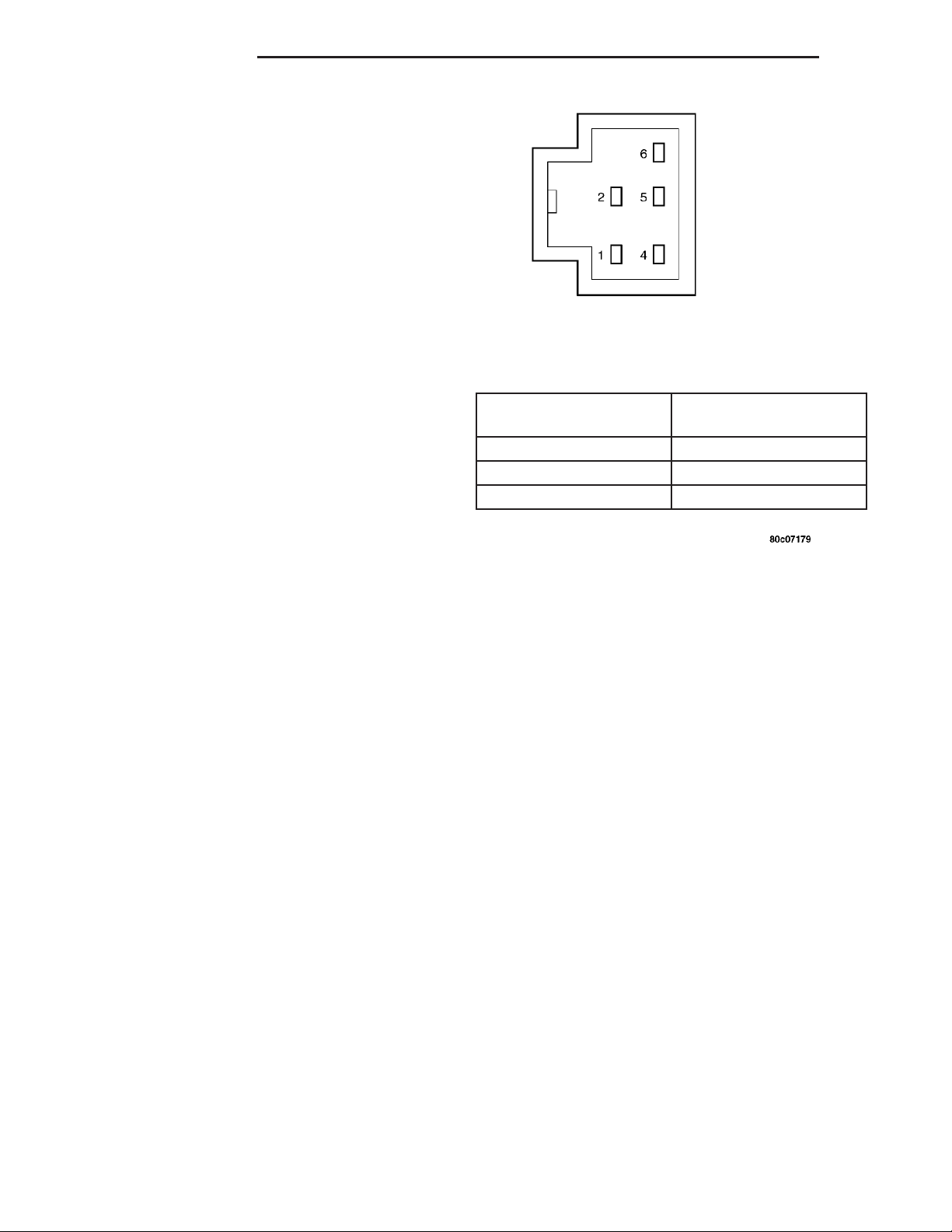
POWER LOCK SWITCH TEST TABLE
SWITCH POSITION RESISTANCE BETWEEN
PINS1&5
NEUTRAL 10 KILOHMS ±1%
LOCK 820 OHMS ±5%
UNLOCK 330 OHMS ±5%
POWER LOCK SWITCH
DIAGNOSIS AND TESTING - POWER LOCK
SWITCH
The Light-Emitting Diode (LED) illumination lamp
of the power lock switch receives battery current
through a fuse in the Integrated Power Module (IPM)
on a fused ignition switch output (run) circuit. The
power lock switch on the driver side front door trim
panel is integral to the driver door module. (Refer to
8 - ELECTRICAL/POWER LOCKS/DOOR MODULE
- DIAGNOSIS AND TESTING). If the power lock
switch operates, but the LED is inoperative, check
for battery current at the switch with the ignition
switch in the On position. If OK, replace the faulty
switch. Refer to the appropriate wiring information.
The wiring information includes wiring diagrams,
proper wire and connector repair procedures, details
of wire harness routing and retention, connector pinout information and location views for the various
wire harness connectors, splices and grounds.
(1) Disconnect and isolate the battery negative
cable. Remove the power lock switch from the door
trim panel. Disconnect the door wire harness connector for the power lock switch from the switch connector receptacle.
(2) Test the power lock switch resistance. See the
Power Lock Switch Test chart to determine if the
resistance is correct for the switch in each switch
position (Fig. 1). If not OK, replace the faulty power
lock switch as required.
Fig. 1 Power Lock Switch Connector Receptacle
REMOVAL
The power lock switch on the driver side front door
trim panel is integral to the driver door module.
(Refer to 8 - ELECTRICAL/POWER LOCKS/DOOR
MODULE - REMOVAL).
(1) Disconnect and isolate the battery negative
cable.
(2) Remove the door trim panel (Refer to 23 BODY/DOOR - FRONT/TRIM PANEL - REMOVAL).
(3) Remove the switch from the trim panel bezel.
INSTALLATION
(1) Insert switch to trim panel bezel.
(2) Install door trim panel (Refer to 23 - BODY/
DOOR - FRONT/TRIM PANEL - INSTALLATION).
(3) Connect battery negative cable.
Page 5

DR POWER LOCKS 8N - 5
DOOR LOCK MOTOR
DESCRIPTION
The lock mechanisms are actuated by a reversible
electric motor mounted within each door. The power
lock motors are integral to the door latch units.
The power lock motors cannot be adjusted or
repaired and, if faulty or damaged, the door latch
unit must be replaced.
OPERATION
The door lock motors are controlled by the instrument cluster. A positive and negative battery connection to the two motor terminals will cause the motor
to move in one direction. Reversing the current will
cause the motor to move in the opposite direction.
DIAGNOSIS AND TESTING - DOOR LOCK
MOTOR
The most reliable, efficient, and accurate means to
diagnose the power lock system requires the use of a
DRBIIIt scan tool and the proper Diagnostic Procedures manual. The DRBIIIt scan tool can provide
confirmation that the PCI data bus is functional, that
all of the electronic modules are sending and receiving the proper messages on the PCI data bus, and
that the power lock motors are being sent the proper
hard wired outputs by the door modules for them to
perform their power lock system functions.
Refer to the appropriate wiring information. The
wiring information includes wiring diagrams, proper
wire and connector repair procedures, details of wire
harness routing and retention, connector pin-out
information and location views for the various wire
harness connectors, splices and grounds.
DRIVER DOOR MODULE
DESCRIPTION
A Driver Door Module (DDM) is used on all models
equipped with power locks, power windows, and
power mirrors. The DDM houses the following
switches:
• Power Lock Switch - The DDM includes a
two-way, momentary, resistor multiplexed switch to
control the power lock system.
• Power Mirror Selector Switch - A three-posi-
tion rocker switch in the DDM selects the right or
left power mirror for adjustment, or turns the power
mirror system Off.
• Power Mirror Adjustment Switches - Four
momentary, arrowhead shaped, directional switches
allow the driver to adjust the selected power mirror
in the Up, Down, Right, or Left directions.
• Power Window Lockout Switch - A two-way,
latching, push-button switch in the DDM allows the
vehicle operator to lock out the power window
switches on each passenger door so that the passenger door power windows may be operated only from
the master switches in the DDM.
• Power Window Switches - The DDM houses a
two-way, momentary power window switch for the
driver side front door. This switch also has a second
detent in the Down direction and internal circuitry to
provide an Auto-Down feature for the driver side
front door power window. In addition to the power
window switch for its own door, the DDM houses
individual master switches for each passenger door
power window.
The DDM also incorporates several green LightEmitting Diodes (LEDs) that illuminate the power
lock and power window switch paddles, and the
power mirror switch directional buttons to improve
switch visibility in dark ambient lighting conditions.
The DDM cannot be adjusted or repaired and, if
faulty or damaged, the entire DDM unit must be
replaced.
OPERATION
The Driver Door Module (DDM) combines a power
lock switch, a driver power window switch with an
Auto-down feature, master switches for each passenger door power window, a power window lockout
switch, a power mirror selector switch, and four
power mirror adjustment switches in a single unit.
The switches in the DDM can be diagnosed using
conventional diagnostic tools and methods.
Power Lock Switch
The DDM power lock switch circuitry is connected
in series between ground and the driver door switch
mux input of the instrument cluster. Each power lock
switch position (Lock, Unlock, and Neutral) provides
a different resistance value to the instrument cluster
input, which allows the instrument cluster to sense
the switch position. Based upon the power lock
switch input, the instrument cluster controls the battery and ground feed outputs to the individual power
lock motors to lock or unlock the door latches. The
Light-Emitting Diode (LED) in the DDM power lock
switch is connected to battery current through the
power window circuit breaker in the Integrated
Power Module (IPM) on a fused ignition switch output (run-acc) circuit so that the switch will be illuminated whenever the ignition switch is in the On or
Accessory positions.
Power Window Switches
The DDM power window switch circuitry is connected to battery current through a circuit breaker in
Page 6
8N - 6 POWER LOCKS DR
DRIVER DOOR MODULE (Continued)
the Integrated Power Module (IPM) on a fused ignition switch output (run-acc) circuit so that the power
windows will operate whenever the ignition switch is
in the On or Accessory positions. Each two-way,
momentary master passenger power window switch
in the DDM provides battery current and ground to
the individual power window switches on each passenger door so that the power window switch controls
the battery current and ground feeds to its respective
power window motor. The DDM switch for the driver
side front door power window is labeled “Auto” and
includes an auto-down feature. When this switch is
depressed to a second momentary detent position and
released, the driver door power window is automatically operated through an internal circuit and relay
to its fully lowered position. The Auto-down event is
cancelled if the switch paddle is depressed a second
time in either the Up or Down direction. When the
two position window lockout switch in the DDM is
depressed and latched in the lockout position, the
battery current feed to each of the individual passenger power window switches is interrupted so that the
passenger door power windows can only be operated
from the master switches in the DDM. The window
lockout switch also controls the battery current feed
for the LED in each passenger power window switch
so that the switch will not be illuminated when it is
locked out.
Power Mirror Switches
The DDM power mirror switch circuitry is connected to battery current through a fuse in the IPM
on a fused B(+) circuit so that the power mirrors
remain operational regardless of the ignition switch
position. A rocker type selector switch has three positions, one to select the right mirror, one to select the
left mirror, and a neutral Off position. After the right
or left mirror is selected, one of four directional buttons is depressed to move the selected mirror Up,
Down, Right or Left. The DDM power mirror switch
circuitry controls the battery current and ground
feeds to each of the four (two in each mirror head)
power mirror motors. The Light-Emitting Diode
(LED) in the DDM power mirror switch is connected
to battery current through the power window circuit
breaker in the IPM on a fused ignition switch output
(run-acc) circuit so that the switch directional buttons will be illuminated whenever the ignition switch
is in the On or Accessory positions.
DIAGNOSIS AND TESTING - DRIVER DOOR
MODULE
The Light-Emitting Diode (LED) illumination
lamps for all of the Driver Door Module (DDM)
power window, power lock, and power mirror
switches receive battery current through the power
window circuit breaker in the Integrated Power Module (IPM). If all of the LEDs are inoperative in the
DDM, be certain to diagnose the power window system before replacing the switch unit. (Refer to 8 ELECTRICAL/POWER WINDOWS - DIAGNOSIS
AND TESTING). If only one LED in the DDM is
inoperative, replace the faulty DDM. If the driver
side front door power window operates in a normal
manner, but the Auto-Down feature is inoperative,
replace the faulty DDM. Refer to the appropriate wiring information. The wiring information includes wiring diagrams, proper wire and connector repair
procedures, details of wire harness routing and
retention, connector pin-out information and location
views for the various wire harness connectors, splices
and grounds.
(1) Disconnect and isolate the battery negative
cable. Remove the DDM from the door trim panel.
Disconnect the door wire harness connectors for the
DDM from the DDM connector receptacles.
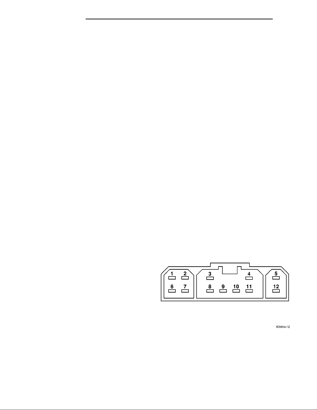
(2) Test the DDM switch continuity. See the Driver
Door Module Switch Tests chart to determine if the
continuity is correct for the suspect switches in each
switch position (Fig. 2) and/or (Fig. 3). If not OK,
replace the faulty DDM as required.
Fig. 2 Driver Door Module Connector C1 Receptacle
Page 7
DR POWER LOCKS 8N - 7
DRIVER DOOR MODULE (Continued)
DRIVER DOOR MODULE SWITCH TESTS
LEFT FRONT DOWN PINS9&12
RIGHT FRONT UP PINS3&9
RIGHT FRONT DOWN PINS6&9
LEFT REAR UP PINS4&9
LEFT REAR DOWN PINS9&10
RIGHT REAR UP PINS2&9
RIGHT REAR DOWN PINS1&9
POWER WINDOW LOCKOUT SWITCH
SWITCH POSITION CONTINUITY BETWEEN
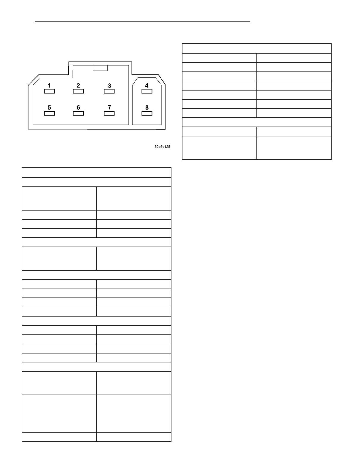
Fig. 3 Driver Door Module Connector C2 Receptacle
DRIVER DOOR MODULE SWITCH TESTS
POWER LOCK SWITCH
RESISTANCE BETWEEN
SWITCH POSITION
NEUTRAL 10 KILOHMS ± 1%
LOCK 820 OHMS ± 5%
UNLOCK 330 OHMS ± 5%
POWER MIRROR SWITCH
SWITCH POSITION
LEFT MIRROR SELECTED
UP PINS1&3
DOWN PINS2&3
RIGHT PINS2&3
LEFT PINS3&6
RIGHT MIRROR SELECTED
UP PINS3&7
DOWN PINS2&3
RIGHT PINS2&3
LEFT PINS3&4
POWER WINDOW SWITCH
SWITCH POSITION CONTINUITY BETWEEN
NEUTRAL PINS1&8,PINS2&8,
LEFT FRONT UP PINS5&9
CONNECTOR C-1 PINS
7&11
CONTINUITY BETWEEN
PINS OF CONNECTOR
C-2
PINS OF CONNECTOR
C-1
PINS3&8,PINS4&8,
PINS5&8,PINS6&8,
PINS 8 & 10, PINS 8 &
12
OFF (SWITCH BUTTON
RAISED - NOT
DEPRESSED)
REMOVAL
(1) Disconnect and isolate the battery negative
cable.
(2) Remove the door trim panel (Refer to 23 -
BODY/DOOR - FRONT/TRIM PANEL - REMOVAL).
(3) Remove the driver door module from the trim
panel bezel.
INSTALLATION
(1) Install driver door module to trim panel bezel.
(2) Install door trim panel (Refer to 23 - BODY/
DOOR - FRONT/TRIM PANEL - INSTALLATION).
(3) Connect battery negative cable.
REMOTE KEYLESS ENTRY
MODULE
DESCRIPTION
When an RKE lock message is sent to the instrument cluster, the instrument cluster actuates the
door locks, the interior lighting is turned off, the
horn chirps (if this feature is enabled), the park
lamps flash (if this feature is enabled) and, if the
vehicle is so equipped, the Vehicle Theft Security
System (VTSS) is armed. When an RKE unlock message is sent to the instrument cluster, the instrument
cluster actuates the driver side front door (or all
doors if this feature is enabled) unlock, the interior
lighting is turned on and, if the vehicle is so
equipped, the VTSS is disarmed.
When an RKE panic message is sent to the instrument cluster, the instrument cluster actuates the
driver side front door (or all doors if this feature is
enabled) unlock, the interior lighting is turned on
and, if the vehicle is so equipped, the VTSS is disarmed. The panic message will also cause the exterior lamps (including the headlights) to flash, and
PIN 9 OF CONNECTOR
C-1&PIN8OF
CONNECTOR C-2
Page 8

8N - 8 POWER LOCKS DR
REMOTE KEYLESS ENTRY MODULE (Continued)
the horn to sound for about three minutes, or until a
second panic message is sent to the instrument cluster. A vehicle speed of about 25.7 kilometers-per-hour
(15 miles-per-hour) will also cancel the panic event.
Refer to the owner’s manual for more information
on the features, use and operation of the RKE system.
OPERATION
Whenever the vehicle battery power is interrupted,
the Remote Keyless Module (RKE) Module will retain
all vehicle access codes in its memory. When replacing or adding a key fob transmitter (maximum of 4) a
DRB IIIt scan tool is required to program the RKE
Module to accept the new Vehicle Access Code if a
customer owned transmitter is not available.
If a functioning transmitter is available, (Refer to 8
- ELECTRICAL/POWER LOCKS/KEYLESS ENTRY
TRANSMITTER - STANDARD PROCEDURE)
Fig. 4 REMOTE KEYLESS ENTRY MODULE
1 - INSTRUMENT CLUSTER
2 - REMOTE KEYLESS ENTRY MODULE
DIAGNOSIS AND TESTING - REMOTE KEYLESS
ENTRY MODULE
Refer to the appropriate wiring information. The
wiring information includes wiring diagrams, proper
wire and connector repair procedures, further details
on wire harness routing and retention, as well as
pin-out and location views for the various wire harness connectors, splices and grounds. Refer to the
proper Body Diagnostic Procedures Manual for testing the Remote Keyless Entry system using a DRB
IIIt scan tool.
REMOVAL
(1) Disconnect and isolate the battery negative
cable.
(2) Remove the instrument cluster (Refer to 8 ELECTRICAL/INSTRUMENT CLUSTER - REMOVAL).
(3) Remove remote keyless entry module from
instrument cluster (Fig. 4).
INSTALLATION
(1) Install remote keyless entry module to instrument cluster.
(2) Install instrument cluster (Refer to 8 - ELECTRICAL/INSTRUMENT CLUSTER - INSTALLATION).
(3) Connect the battery negative cable.
REMOTE KEYLESS ENTRY
TRANSMITTER
DIAGNOSIS AND TESTING - REMOTE KEYLESS
ENTRY TRANSMITTER
Using special tool 9001, first test to ensure that
the transmitter is functioning. Typical testing distance is 2.5 centimeters (1 inch) for Asian transmitters and 30.5 centimeters (12 inches) for all others.
To test, position the transmitter as shown (Fig. 5).
Press any transmitter button, then test each button
individually. The tool will beep if a radio signal
strength that lights five or more LED’s is detected.
Repeat this test three times. If transmitter fails any
of the test refer to the Diagnostic Procedures manual.
Fig. 5 TRANSMITTER DIAGNOSIS
Page 9

DR POWER LOCKS 8N - 9
REMOTE KEYLESS ENTRY TRANSMITTER (Continued)
STANDARD PROCEDURE
STANDARD PROCEDURE - RKE TRANSMITTER
BATTERIES
NOTE: Do not disturb the metal terminal near the
batteries. Avoid touching the new batteries. Skin
oils may cause battery deterioration. If batteries are
touched, clean with rubbing alcohol.
The Remote Keyless Entry (RKE) transmitter case
snaps open and shut for battery access. To replace
the RKE transmitter batteries:
(1) Using a thin coin, gently pry at the notch in
the center seam of the RKE transmitter case halves
near the key ring until the two halves unsnap. Be
careful not to damage the rubber gasket when separating the case halves.
(2) Lift the back half of the transmitter case off of
the RKE transmitter.
(3) Remove the two batteries from the RKE transmitter.
(4) Replace the two batteries with new 3V lithium
2016 cell. Install the batteries with the positive terminal up. Reference the “+ SIDE UP” on the inside of
the bottom half of the transmitter case.
(5) Align the two RKE transmitter case halves
with each other, and squeeze them firmly and evenly
together until they snap back into place. Test transmitter operation.
(7) Test the horn chirp feature by pressing the
LOCK button.
If a chime is not heard, program mode was canceled before the feature could be disabled. If necessary, repeat the procedure.
To ENABLE the horn chirp feature, repeat the
above procedure.
OPTICAL CHIRP (FLASH) DISABLING / ENABLING
The optical chirp can be toggled using a DRB IIIt
or by using the Remote Keyless Entry (RKE) transmitter that is already programmed to the vehicle.
To DISABLE (cancel) the optical chirp feature:
(1) Enter the vehicle and close all doors.
(2) Fasten the seat belt (this will cancel the seat
belt chime).
(3) Turn the ignition to the ON position.
(4) Press and hold the LOCK button for 4 seconds.
Within 6 seconds with the LOCK button still
depressed, press the PANIC button. When a single
chime is heard, release both buttons.
(5) Turn the ignition OFF.
(6) Turn the ignition ON or wait 60 seconds.
(7) Test the optical chirp feature by pressing the
LOCK button.
If a chime is not heard, program mode was canceled before the feature could be disabled. If necessary, repeat the procedure.
To ENABLE the optical chirp feature, repeat the
above procedure.
STANDARD PROCEDURE - RKE TRANSMITTER
CUSTOMER PREFERENCES
AUTOMATIC (ROLLING) LOCKS
The rolling locks feature can be toggled ON/OFF
by using the DRB IIIt only.
HORN CHIRP DISABLING / ENABLING
The horn chirp can be toggled using a DRB IIIt or
by using the Remote Keyless Entry (RKE) transmitter that is already programmed to the vehicle.
To DISABLE (cancel) the horn chirp feature:
(1) Enter the vehicle and close all doors.
(2) Fasten the seat belt (this will cancel the seat
belt chime).
(3) Turn the ignition to the ON position.
(4) Press and hold the LOCK button for 4 seconds.
Within 6 seconds with the LOCK button still
depressed, press the UNLOCK button. When a single
chime is heard, release both buttons.
(5) Turn the ignition OFF.
(6) Turn the ignition ON or wait 60 seconds.
UNLOCK SEQUENCE
The unlock sequence can be toggled using a DRB
IIIt or by using the Remote Keyless Entry (RKE)
transmitter that is already programmed to the vehicle.
To toggle between Driver door first and Unlock all
doors function:
(1) Enter the vehicle and close all doors.
(2) Fasten the seat belt (this will cancel the seat
belt chime).
(3) Turn the ignition to the ON position.
(4) Press and hold the UNLOCK button for 4 seconds. Within 6 seconds with the UNLOCK button
still depressed, press the LOCK button. When a single chime is heard, release both buttons.
(5) Turn the ignition OFF.
(6) Turn the ignition ON or wait 60 seconds.
If a chime is not heard, program mode was canceled before the feature could be disabled. If necessary, repeat the procedure.
To toggle this feature, repeat the above procedure.
Page 10

8N - 10 POWER LOCKS DR
REMOTE KEYLESS ENTRY TRANSMITTER (Continued)
STANDARD PROCEDURE - RKE TRANSMITTER
PROGRAMING
New Remote Keyless Entry (RKE) transmitters can
be programed using the DRB IIIt scan tool and the
proper Diagnostic Procedures manual. The DRB IIIt
scan tool can provide confirmation that the PCI data
bus is functional, and that all of the electronic modules are sending and receiving the proper messages
on the PCI data bus.
The following procedure can be used as long as one
programmed transmitter is available:
NOTE: When entering program mode using that
programmed fob, ALL currently programmed fobs
will be erased and they will have to be reprogrammed for the vehicle. If program mode is
entered and no action is performed, the previously
programmed fobs will continue to function.
(1) Enter the vehicle and close all doors.
(2) Fasten the seat belt (this will cancel the seat
belt chime). Turn the ignition to the RUN position.
(3) Press and hold the UNLOCK button on a programmed transmitter for 4 to 10 seconds. Within the
4 to 10 seconds with the UNLOCK button still
depressed, press the PANIC button for one second.
When a single chime is heard, release both buttons.The chime indicates the system is in program
mode.
(4) Press and release both the LOCK and
UNLOCK buttons simultaneously on a fob to be programmed. A single chime will be heard, this indicates
the fob has been recognized.
(5) Press and release any button on the same fob.
A single chime will be heard, this indicates the fob
has been programmed.
(6) Repeat steps 4 and 5 for up to a total of 4 fobs.
(7) Turn the ignition OFF.
(8) Turn the ignition ON or wait 60 seconds.
The vehicle will remain in program mode for up to
60 seconds from when the original chime (step 3) was
heard. After 60 seconds, all programmed transmitters
will function normally.
SPECIFICATIONS - REMOTE KEYLESS ENTRY
TRANSMITTER
RANGE
Normal operation range is up to a distance of 3 to
7 meters (10 to 23 ft.) of the vehicle. Range may be
better or worse depending on the environment
around the vehicle.
Page 11

DR POWER MIRRORS 8N - 11
POWER MIRRORS
TABLE OF CONTENTS
page page
POWER MIRRORS
DESCRIPTION .........................11
OPERATION ...........................11
DIAGNOSIS AND TESTING - POWER
MIRRORS ...........................11
AUTOMATIC DAY / NIGHT MIRROR
DESCRIPTION .........................12
OPERATION ...........................12
DIAGNOSIS AND TESTING - AUTOMATIC DAY
/ NIGHT MIRROR ......................12
POWER MIRRORS
DESCRIPTION
AUTOMATIC DAY/NIGHT MIRROR
The automatic day/night mirror system is able to
automatically change the reflectance of the inside
rear view mirror in order to reduce the glare of headlamps approaching the vehicle from the rear. The
automatic day/night rear view mirror receives battery current through a fuse in the Integrated Power
Module (IPM) only when the ignition switch is in the
On position.
OUTSIDE REAR VIEW MIRROR
The power operated outside rear view mirrors
allow the driver to adjust both outside mirrors electrically from the driver side front seat position by
operating a switch on the driver side front door trim
panel. The power mirrors receive a non-switched battery feed through a fuse in the Integrated Power
Module (IPM) so that the system will remain operational, regardless of the ignition switch position.
OPERATION
AUTOMATIC DAY/NIGHT MIRROR
A switch located on the bottom of the automatic
day/night mirror housing allows the vehicle operator
to select whether the automatic dimming feature is
operational. When the automatic day/night mirror is
turned on, the mirror switch is lighted by an integral
Light-Emitting Diode (LED). The mirror will automatically disable its self-dimming feature whenever
the vehicle is being driven in reverse.
REMOVAL .............................13
POWER MIRROR SWITCH
DIAGNOSIS AND TESTING - POWER MIRROR
SWITCH ............................13
REMOVAL .............................13
SIDEVIEW MIRROR
REMOVAL .............................13
Refer to the owner’s manual for more information
on the features, use and operation of the automatic
day/night mirror system.
OUTSIDE REAR VIEW MIRROR
The heated mirrors include an electric heating grid
behind the mirror glass in each outside mirror, which
can clear the mirror glass of ice, snow, or fog. (Refer
to 8 - ELECTRICAL/HEATED MIRRORS DESCRIPTION) for more information.
DIAGNOSIS AND TESTING - POWER MIRRORS
WIRING VOLTAGE TEST
The following wiring test determines whether or
not voltage is continuous through the body harness
to switch.
(1) Remove the power mirror switch (Refer to 8 ELECTRICAL/POWER LOCKS/DOOR MODULE REMOVAL).
(2) Disconnect wire harness connector from back of
power mirror switch.
(3) Connect the clip end of a 12 volt test light to
Pin 5 in the mirror switch harness connector. Touch
the test light probe to Pin 3.
If the test light illuminates, the wiring circuit
between the battery and switch is OK.
If the lamp does not illuminate, first check fuse in
the Integrated Power Module (IPM). If fuse is OK,
then check for a broken wire.
Refer to the appropriate wiring information. The
wiring information includes wiring diagrams, proper
wire and connector repair procedures, details of wire
harness routing and retention, connector pin-out
information and location views for the various wire
harness connectors, splices and grounds.
Page 12

8N - 12 POWER MIRRORS DR
POWER MIRRORS (Continued)
POWER MIRROR MOTOR TEST
If the power mirror switch is receiving proper current and ground and mirrors do not operate, proceed
with power mirror motor test. Refer to the appropriate wiring information. The wiring information
includes wiring diagrams, proper wire and connector
repair procedures, details of wire harness routing
and retention, connector pin-out information and
location views for the various wire harness connectors, splices and grounds.
(1) Remove the power mirror switch (Refer to 8 ELECTRICAL/POWER LOCKS/DOOR MODULE REMOVAL).
(2) Disconnect wire harness connector to power
mirror switch (Fig. 1).
(3) Using two jumper wires:
• Connect one to a 12 volt source
• Connect the other to a good body ground
• Refer to the Mirror Motor Test Chart for proper
wire connections at the switch connector
Fig. 1 POWER MIRROR SWITCH CONNECTOR
MIRROR MOTOR TEST CHART
12 VOLTS GROUND MIRROR REACTION
SWITCH CONNECTOR RIGHT LEFT
PIN 1 PIN 2 - UP
PIN 6 PIN 2 - LEFT
PIN 2 PIN 1 - DOWN
PIN 2 PIN 6 - RIGHT
PIN 7 PIN 2 UP PIN 4 PIN 2 LEFT PIN 2 PIN 7 DOWN PIN 2 PIN 4 RIGHT -
(4) If results shown in table are not obtained,
check for open or shorted circuit. Replace mirror
assembly as necessary.
AUTOMATIC DAY / NIGHT
MIRROR
DESCRIPTION
The automatic day/night mirror uses a thin layer
of electrochromic material between two pieces of conductive glass to make up the face of the mirror.
When the mirror switch is in the On position, two
photocell sensors are used by the mirror circuitry to
monitor external light levels and adjust the reflectance of the mirror.
OPERATION
The ambient photocell sensor is located on the forward-facing (windshield side) of the rear view mirror
housing, and detects the ambient light levels outside
of the vehicle. The headlamp photocell sensor is
located inside the rear view mirror housing behind
the mirror glass and faces rearward, to detect the
level of the light being received at the rear window
side of the mirror. When the circuitry of the automatic day/night mirror detects that the difference
between the two light levels is too great (the light
level received at the rear of the mirror is much
higher than that at the front of the mirror), it begins
to darken the mirror.
The automatic day/night mirror circuitry also monitors the transmission using an input from the
backup lamp circuit. The mirror circuitry is programmed to automatically disable its self-dimming
feature whenever it senses that the transmission
backup lamp circuit is energized.
The automatic day/night mirror is a completely
self-contained unit and cannot be repaired. If faulty
or damaged, the entire mirror assembly must be
replaced.
DIAGNOSIS AND TESTING - AUTOMATIC DAY /
NIGHT MIRROR
For complete circuit diagrams, refer to the appropriate wiring information. The wiring information
includes wiring diagrams, proper wire and connector
repair procedures, details of wire harness routing
and retention, connector pin-out information and
location views for the various wire harness connectors, splices and grounds.
(1) Check the fuse in the Integrated Power Module
(IPM). If OK, go to Step 2. If not OK, repair the
shorted circuit or component as required and replace
the faulty fuse.
(2) Turn the ignition switch to the On position.
Check for battery voltage at the fuse in the IPM. If
OK, go to Step 3. If not OK, repair the open circuit to
the ignition switch as required.
Page 13

DR POWER MIRRORS 8N - 13
AUTOMATIC DAY / NIGHT MIRROR (Continued)
(3) Turn the ignition switch to the Off position.
Disconnect and isolate the battery negative cable.
Unplug the wire harness connector from the automatic day/night mirror (Fig. 2). Connect the battery
negative cable. Turn the ignition switch to the On
position. Check for battery voltage at the fused ignition switch output (run/start) circuit cavity of the
automatic day/night mirror wire harness connector. If
OK, go to Step 4. If not OK, repair the open circuit to
the IPM as required.
Fig. 2 Automatic Day/Night Mirror
1 - REAR FACING SENSOR
2 - CONNECTOR
3 - FORWARD FACING SENSOR
4 - SWITCH
(4) Turn the ignition switch to the Off position.
Disconnect and isolate the battery negative cable.
Check for continuity between the ground circuit cavity of the automatic day/night mirror wire harness
connector and a good ground. There should be continuity. If OK, go to Step 5. If not OK, repair the circuit to ground as required.
(5) Connect the battery negative cable. Turn the
ignition switch to the On position. Set the parking
brake. Place the transmission gear selector lever in
the Reverse position. Check for battery voltage at the
backup lamp switch output circuit cavity of the automatic day/night mirror wire harness connector. If
OK, go to Step 6. If not OK, repair the open circuit
as required.
(6) Turn the ignition switch to the Off position.
Disconnect the battery negative cable. Plug in the
automatic day/night mirror wire harness connector.
Connect the battery negative cable. Turn the ignition
switch to the On position. Place the transmission
gear selector lever in the Neutral position. Place the
mirror switch in the On (the LED in the mirror
switch is lighted) position. Cover the forward facing
ambient photocell sensor to keep out any ambient
light.
NOTE: The ambient photocell sensor must be covered completely, so that no light reaches the sensor. Use a finger pressed tightly against the sensor,
or cover the sensor completely with electrical tape.
(7) Shine a light into the rearward facing headlamp photocell sensor. The mirror glass should
darken. If OK, go to Step 8. If not OK, replace the
faulty automatic day/night mirror unit.
(8) With the mirror glass darkened, place the
transmission gear selector lever in the Reverse position. The mirror should return to its normal reflectance. If not OK, replace the faulty automatic day/
night mirror unit.
REMOVAL
For removal procedures, (Refer to 23 - BODY/INTERIOR/REAR VIEW MIRROR - REMOVAL).
POWER MIRROR SWITCH
DIAGNOSIS AND TESTING - POWER MIRROR
SWITCH
The power mirror switch is included with the
Driver Door Module. (Refer to 8 - ELECTRICAL/
POWER LOCKS/DOOR MODULE - DIAGNOSIS
AND TESTING).
REMOVAL
The power mirror switch is included with the
Driver Door Module. (Refer to 8 - ELECTRICAL/
POWER LOCKS/DOOR MODULE - REMOVAL).
SIDEVIEW MIRROR
REMOVAL
(Refer to 23 - BODY/EXTERIOR/SIDE VIEW MIRROR - REMOVAL).
Page 14

8N - 14 POWER SEATS DR
POWER SEATS
TABLE OF CONTENTS
page page
POWER SEATS
DESCRIPTION .........................14
OPERATION ...........................14
DIAGNOSIS AND TESTING - POWER SEAT
SYSTEM ............................14
DRIVER SEAT SWITCH
DESCRIPTION .........................15
OPERATION ...........................15
DIAGNOSIS AND TESTING - DRIVER SEAT
SWITCH ............................15
REMOVAL .............................16
INSTALLATION .........................16
PASSENGER SEAT SWITCH
DESCRIPTION .........................16
OPERATION ...........................17
DIAGNOSIS AND TESTING - PASSENGER
SEAT SWITCH ........................17
POWER SEATS
DESCRIPTION
The power seat system option allows the driver or
passenger to electrically adjust the seat position for
optimum control and comfort using the power seat
switches located on the outboard seat cushion side
shield. The power seat system allows the seating
position to be adjusted forward, rearward, front up,
front down, rear up, or rear down. The power seat
system receives battery current through a fuse in the
Integrated Power Module, regardless of the ignition
switch position. The power seat system includes the
following components:
• Driver Power Seat Switch
• Passenger Power Seat Switch
• Driver Power Seat Track
• Passenger Power Seat Track
• Power Lumbar Adjuster(s)
Some models equipped with the power seat option
also feature a power operated lumbar support in the
seat back. The power lumbar support allows the user
to inflate or deflate a bladder located in the lower
seat back to achieve optimum comfort and support in
the lower lumbar region of the spinal column. The
power lumbar support shares the battery feed circuit
of the power seat system.
Following are general descriptions of the major
components in the power seat system. Refer to
Heated Seat System for information on the individ-
REMOVAL .............................17
INSTALLATION .........................18
POWER SEAT TRACK
DESCRIPTION .........................18
OPERATION ...........................18
DIAGNOSIS AND TESTING - POWER SEAT
TRACK .............................18
REMOVAL .............................19
INSTALLATION .........................19
LUMBAR CONTROL SWITCH
DESCRIPTION .........................19
OPERATION ...........................19
REMOVAL .............................19
LUMBAR MOTOR
DESCRIPTION .........................19
OPERATION ...........................20
DIAGNOSIS AND TESTING - LUMBAR MOTOR
ually controlled heated front seats. Refer to the owner’s manual in the vehicle glove box for more
information on the features, use and operation of the
power seat system.
..20
OPERATION
The power seat system allows the driver and/or
front passenger seating positions to be adjusted electrically and independently using the separate power
seat switches found on the outboard seat cushion
side shield of each front seat. See the owner’s manual
in the vehicle glove box for more information on the
features, use and operation of the power seat system.
DIAGNOSIS AND TESTING - POWER SEAT
SYSTEM
Before any testing of the power seat system is
attempted, the battery should be fully-charged and
all wire harness connections and pins checked to
ensure proper continuity and grounds. For circuit
descriptions and diagrams, refer to Wiring Diagrams.
With the dome lamp on, apply the power seat
switch in the direction of the failure. If the dome
lamp dims, the seat may be jamming. Check under
and behind the seat for binding or obstructions. If
the dome lamp does not dim, proceed with testing of
the individual components and circuits.
Page 15

DR POWER SEATS 8N - 15
DRIVER SEAT SWITCH
DESCRIPTION
Fig. 1 DR Power Seat Switch
1 - POWER SEAT SWITCH ASSEMBLY
2 - FRONT SEAT CUSHION ADJUSTMENT BUTTON
3 - COMPLETE SEATADJUSTMENT BUTTON
4 - REAR SEAT CUSHION ADJUSTMENT BUTTON
5 - LUMBAR ADJUSTMENT BUTTON
moved in the opposite direction, the battery feed and
ground path to the motor are reversed through the
switch contacts. This causes the adjuster motor to
run in the opposite direction.
No power seat switch should be held applied in any
direction after the adjuster has reached its travel
limit. The power seat adjuster motors each contain a
self-resetting circuit breaker to protect them from
overload. However, consecutive or frequent resetting
of the circuit breaker must not be allowed to continue, or the motor may be damaged.
DIAGNOSIS AND TESTING - DRIVER SEAT
SWITCH
For circuit descriptions and diagrams, refer to Wiring.
(1) Disconnect and isolate the battery negative
cable.
(2) Remove the power seat switch from the power
seat.
(3) Use an ohmmeter to test the continuity of the
power seat switches in each position. See the Power
Seat Switch Continuity chart (Fig. 2). If OK, refer to
Power Seat Track Diagnosis and Testing in this
group. If not OK, replace the faulty power seat
switch.
The power seat on this model can be adjusted in
eight different directions, up, down, front up, front
down, rear up, rear down, rearward and forward.
The power seat switch (Fig. 1) on this model has an
additional switch knob for adjusting the power lumbar support. The power seat switch is located on the
outboard side of the seat cushion on the seat cushion
side shield. Refer to the owner’s manual in the vehicle glove box for more information on the power seat
switch functions and the seat adjusting procedures.
The individual switches in the power seat switch
assembly cannot be repaired. If one switch is damaged or faulty, the entire power seat switch assembly
must be replaced.
OPERATION
When a power switch control knob or knobs are
actuated, a battery feed and a ground path are
applied through the switch contacts to the power seat
track or recliner adjuster motor. The selected
adjuster motor operates to move the seat track or
recliner through its drive unit in the selected direction until the switch is released, or until the travel
limit of the adjuster is reached. When the switch is
Fig. 2 Testing Driver Power Seat Switch
DRIVER POWER SEAT SWITCH TEST TABLE
DRIVER SWITCH
POSITION
OFF B-N, B-J, B-M
VERTICAL UP A-E, A-M, B-N, B-E
VERTICAL DOWN A-J, A-N, B-M, B-E
CONTINUITY BETWEEN
B-E, B-L, B-K
Page 16

8N - 16 POWER SEATS DR
DRIVER SEAT SWITCH (Continued)
DRIVER POWER SEAT SWITCH TEST TABLE
DRIVER SWITCH
POSITION
HORIZONTAL
FORWARD
HORIZONTAL
REARWARD
FRONT TILT UP A-M, B-N
FRONT TILT DOWN A-N, B-M
REAR TILT UP A-E, B-J
REAR TILT DOWN A-J, B-E
LUMBAR OFF O-P, O-R, P-R
LUMPAR UP (INFLATE) O-P, Q-R
LUMBAR DOWN
(DEFLATE)
CONTINUITY BETWEEN
A-L, B-K
A-K, B-L
O-R, P-Q
REMOVAL
(1) Disconnect and isolate the battery negative
cable.
(2) Remove the seat cushion side shield from the
seat. Refer to the Body section of the service manual
for the procedure.
(3) Pull the switch bezel or side shield unit out
from the seat far enough to access the switch wire
harness connector. Gently pry the locking tabs of the
switch away from the wire harness connector and
carefully unplug the connector from the power seat
switch module.
INSTALLATION
(1) Position the power seat switch on the seat
cushion side shield and install the screws that secure
the power seat switch to seat cushion side shield.
(2) Connect the electrical connector.
(3) Install the seat cushion side shield on the seat.
Refer to the Body section of the service manual for
the procedure.
(4) If equipped, install the screw that secures the
recliner lever to the recliner mechanism release shaft
on the outboard side of the front seat.
(5) Connect the battery negative cable.
PASSENGER SEAT SWITCH
DESCRIPTION
Fig. 3 Power Seat Switch Remove/Install
1 - SEAT SIDE SHIELD
2 - POWER SEAT SWITCH
3 - SCREWS
(4) Remove the screws that secure the power seat
switch (Fig. 3).
Fig. 4 DR Power Seat Switch
1 - POWER SEAT SWITCH ASSEMBLY
2 - FRONT SEAT CUSHION ADJUSTMENT BUTTON
3 - COMPLETE SEATADJUSTMENT BUTTON
4 - REAR SEAT CUSHION ADJUSTMENT BUTTON
5 - LUMBAR ADJUSTMENT BUTTON
The power seat on this model can be adjusted in
eight different directions, up, down, front up, front
down, rear up, rear down, rearward and forward.
The power seat switch (Fig. 4) on this model has an
additional switch knob for adjusting the power lumbar support. The power seat switch is located on the
outboard side of the seat cushion on the seat cushion
side shield. Refer to the owner’s manual in the vehicle glove box for more information on the power seat
switch functions and the seat adjusting procedures.
Page 17

DR POWER SEATS 8N - 17
PASSENGER SEAT SWITCH (Continued)
The individual switches in the power seat switch
assembly cannot be repaired. If one switch is damaged or faulty, the entire power seat switch assembly
must be replaced.
OPERATION
When a power switch control knob or knobs are
actuated, a battery feed and a ground path are
applied through the switch contacts to the power seat
track or recliner adjuster motor. The selected
adjuster motor operates to move the seat track or
recliner through its drive unit in the selected direction until the switch is released, or until the travel
limit of the adjuster is reached. When the switch is
moved in the opposite direction, the battery feed and
ground path to the motor are reversed through the
switch contacts. This causes the adjuster motor to
run in the opposite direction.
No power seat switch should be held applied in any
direction after the adjuster has reached its travel
limit. The power seat adjuster motors each contain a
self-resetting circuit breaker to protect them from
overload. However, consecutive or frequent resetting
of the circuit breaker must not be allowed to continue, or the motor may be damaged.
DIAGNOSIS AND TESTING - PASSENGER SEAT
SWITCH
For circuit descriptions and diagrams, refer to Wiring.
(1) Disconnect and isolate the battery negative
cable.
(2) Remove the power seat switch from the power
seat.
(3) Use an ohmmeter to test the continuity of the
power seat switches in each position. See the Power
Seat Switch Continuity chart (Fig. 5). If OK, refer to
Power Seat Track Diagnosis and Testing in this
group. If not OK, replace the faulty power seat
switch.
Fig. 5 Testing Passenger Power Seat Switch
PASSENGER SEAT SWITCH TEST TABLE
PASSENGER SWITCH
POSITION
OFF B-N, B-J, B-M
VERTICAL UP A-E, A-M, B-N, B-E
VERTICAL DOWN A-J, A-N, B-M, B-E
HORIZONTAL
FORWARD
HORIZONTAL
REARWARD
FRONT TILT UP A-M, B-N
FRONT TILT DOWN A-N, B-M
REAR TILT UP A-E, B-J
REAR TILT DOWN A-J, B-E
LUMBAR OFF O-P, O-R, P-R
LUMPAR UP (INFLATE) O-P, Q-R
LUMBAR DOWN
(DEFLATE)
CONTINUITY BETWEEN
B-E, B-L, B-K
A-L, B-K
A-K, B-L
O-R, P-Q
REMOVAL
(1) Disconnect and isolate the battery negative
cable.
(2) Remove the seat cushion side shield from the
seat. Refer to the Body section of the service manual
for the procedure.
(3) Pull the switch bezel or side shield unit out
from the seat far enough to access the switch wire
harness connector. Gently pry the locking tabs of the
switch away from the wire harness connector and
carefully unplug the connector from the power seat
switch module.
Page 18

8N - 18 POWER SEATS DR
PASSENGER SEAT SWITCH (Continued)
Fig. 6 Power Seat Switch Remove/Install
1 - SEAT SIDE SHIELD
2 - POWER SEAT SWITCH
3 - SCREWS
(4) Remove the screws that secure the power seat
switch (Fig. 6).
INSTALLATION
(1) Position the power seat switch on the seat
cushion side shield and install the screws that secure
the power seat switch to seat cushion side shield.
(2) Connect the electrical connector.
(3) Install the seat cushion side shield on the seat.
Refer to the Body section of the service manual for
the procedure.
(4) If equipped, install the screw that secures the
recliner lever to the recliner mechanism release shaft
on the outboard side of the front seat.
(5) Connect the battery negative cable.
POWER SEAT TRACK
DESCRIPTION
The eight-way power seat option includes a power
seat track assembly located under each front seat
(Fig. 7). The power seat track assembly replaces the
standard manually operated seat tracks. The lower
half of the power seat track is secured at the front
with two bolts to the floor panel seat cross member,
and at the rear with two bolts to the floor panel.
Four nuts secure the bottom of the seat cushion
frame to the upper half of the power seat track unit.
The power seat track assembly cannot be repaired,
and is serviced only as a complete assembly. If any
component in this assembly is faulty or damaged, the
entire power seat track must be replaced.
1 - POWER SEAT TRACK ASSEMBLY
2 - SEAT TRACK WIRE HARNESS
3 - SEAT BELT BUCKLE ASSEMBLIES
OPERATION
The power seat track unit includes three reversible
electric motors that are secured to the upper half of
the track unit. Each motor moves the seat adjuster
through a combination of worm-drive gearboxes and
screw-type drive units.
The front and rear of the seat are operated by two
separate vertical adjustment motors. These motors
can be operated independently of each other, tilting
the entire seat assembly forward or rearward; or,
they can be operated in unison by selecting the
proper power seat switch functions, which will raise
or lower the entire seat assembly. The third motor is
the horizontal adjustment motor, which moves the
seat track in the forward and rearward directions.
DIAGNOSIS AND TESTING - POWER SEAT
TRACK
For complete power seat circuit descriptions and
diagrams, refer to Wiring Diagrams.
Operate the power seat switch to move all three
seat motors in each direction. The seat should move
in each of the selected directions. If the power seat
track fails to operate in only one direction, move the
seat track a short distance in the opposite direction
and test again to be certain that the track is not at
its travel limit. If the power seat track still fails to
operate in only one direction, refer to Diagnosis and
Testing of the Power Seat Switch in this section. If
Fig. 7 DR Driver Power Seat Track
Page 19

DR POWER SEATS 8N - 19
POWER SEAT TRACK (Continued)
the power seat track fails to operate in more than
one direction, proceed as follows:
(1) Check the power seat fuse in the power distribution center. If OK, go to Step 2. If not OK, replace
the faulty fuse.
(2) Remove the power seat switch from the seat.
Check for battery voltage at the fused B(+) circuit
cavity of the power seat switch wire harness connector. If OK, go to Step 3. If not OK, repair the open
circuit to the power distribution center as required.
(3) Check for continuity between the ground circuit cavity of the power seat switch wire harness connector and a good ground. There should be
continuity. If OK, go to Step 4. If not OK, repair the
open circuit to ground as required.
(4) Test the power seat switch as described in this
group. If the switch tests OK, check the wire harness
between the power seat switch and the motor for
shorts or opens. If the circuits check OK, replace the
faulty power seat track (adjuster) assembly. If the
circuits are not OK, repair the wire harness as
required.
REMOVAL
(1) Remove the appropriate seat from the vehicle.
(Refer to 23 - BODY/SEATS/SEAT - REMOVAL).
(2) Remove the power seat switch from the seat.
Refer to the procedure in this section of the service
manual.
(3) Remove four seat track mounting nuts from
cushion pan.
(4) Disconnect the power seat electrical and
remove the seat track from the seat cushion.
(5) Remove the necessary components that must
be transferred to the replacement seat track (seat
belt buckles, wire harness, etc.).
INSTALLATION
(1) Install the necessary components that must be
transferred to the replacement seat track (seat belt
buckles, wire harness, etc.).
(2) Position the seat track and install the retaining
nuts on the seat cushion pan studs. Torque the bolts
to 25 N·m.
(3) Route and connect the power seat electrical on
the seat track and cushion pan.
(4) Install the power seat switch on the seat. Refer
to the procedure in this section of the service manual.
(5) Install the seat in the vehicle (Refer to 23 BODY/SEATS/SEAT - INSTALLATION).
(6) Connect the negative battery cable.
LUMBAR CONTROL SWITCH
DESCRIPTION
The power lumbar seat option includes an electrically operated lumbar support mechanism. A single
two-way momentary power lumbar switch is integral
with the power seat switches. The power lumbar
switch is secured to the back of the seat cushion side
shield with screws, and the switch paddle protrudes
through a hole to the outside of the shield. The
switch paddle is located in a shallow depression
molded into the outer surface of the seat cushion side
shield that helps to shroud it from unintentional
actuation when entering or leaving the vehicle.
The power lumbar switches cannot be adjusted or
repaired and, if faulty or damaged, the seat switch
assembly must be replaced.
OPERATION
When the power lumbar switch paddle is actuated,
a battery feed and a ground path are applied through
the switch contacts to the power lumbar adjuster
motor. The motor operates to move the lumbar
adjuster through its drive unit in the selected direction until the switch is released, or until the travel
limit of the adjuster is reached. When the switch is
moved in the opposite direction, the battery feed and
ground path to the motor are reversed through the
switch contacts. This causes the motor to run in the
opposite direction.
The power lumbar switch should not be held
applied in either direction after the adjuster has
reached its travel limit. The power lumbar adjuster
motor contains a self-resetting circuit breaker to protect it from overload. However, consecutive or frequent resetting of the circuit breaker must not be
allowed to continue, or the motor may be damaged.
REMOVAL
The power lumbar switch is integral with the other
power seat switches. Refer to the appropriate driver
or passenger power front seat switch removal and/or
installation procedure.
LUMBAR MOTOR
DESCRIPTION
The power lumbar seat option includes an electrically operated lumbar support mechanism. The only
visible evidence of this option is the separate power
lumbar switch control paddle that is located on the
outboard seat cushion side shield, next to the other
power seat switch control knobs. The power lumbar
adjuster and motor are concealed beneath the seat
back trim cover and padding, where they are secured
Page 20

8N - 20 POWER SEATS DR
LUMBAR MOTOR (Continued)
to a molded plastic back panel and to the seat back
frame.
The power lumbar adjuster cannot be repaired, and
is serviced only as a unit with the seat back frame. If
the power lumbar adjuster or the seat back frame
are damaged or faulty, the entire seat back frame
unit must be replaced (Refer to 23 - BODY/SEATS/
SEAT BACK - REMOVAL).
OPERATION
The power lumbar adjuster mechanism includes a
reversible electric motor that is secured to the
inboard side of the seat back panel and is connected
to a worm-drive gearbox. The motor and gearbox
operate the lumbar adjuster mechanism in the center
of the seat back by extending and retracting a cable
that actuates a lever. The action of this lever compresses or relaxes a grid of flexible slats. The more
this grid is compressed, the more the slats bow outward against the center of the seat back padding,
providing additional lumbar support.
DIAGNOSIS AND TESTING - LUMBAR MOTOR
Actuate the power lumbar switch to move the
power lumbar adjuster in each direction. The power
lumbar adjuster should move in both directions. It
should be noted that the power lumber adjuster normally operates very quietly and exhibits little visible
movement. If the power lumbar adjuster fails to operate in only one direction, move the adjuster a short
distance in the opposite direction and test again to be
certain that the adjuster is not at its travel limit. If
the power lumbar adjuster fails to operate in only
one direction, Test the appropriate power seat switch
as described in this group. If the power lumbar
adjuster fails to operate in either direction, perform
the following tests. For complete circuit diagrams,
refer to Wiring.
(1) Check the power seat circuit breaker. If OK, go
to Step 2. If not OK, replace the faulty power seat
circuit breaker.
(2) Check for battery voltage at the power seat circuit breaker. If OK, go to Step 3. If not OK, repair
the open fused B(+) circuit to the fuse in the Integrated Power Module as required.
(3) Remove the outboard seat cushion side shield
from the seat. Disconnect the seat wire harness connector from the power lumbar switch connector
receptacle. Check for battery voltage at the fused
B(+) circuit cavity of the power seat wire harness
connector for the power lumbar switch. If OK, go to
Step 4. If not OK, repair the open fused B(+) circuit
to the power seat as required.
(4) Check for continuity between the ground circuit cavity of the power seat wire harness connector
for the power lumbar switch and a good ground.
There should be continuity. If OK, go to Step 5. If not
OK, repair the open ground circuit to ground as
required.
(5) Test the power lumbar switch. . If the switch
tests OK, test the circuits of the power seat wire harness between the power lumbar adjuster motor and
the power lumbar switch for shorts or opens. If the
circuits check OK, replace the faulty seat back frame
assembly. If the circuits are not OK, repair the power
seat wire harness as required.
Page 21

DR POWER WINDOWS 8N - 21
POWER WINDOWS
TABLE OF CONTENTS
page page
POWER WINDOWS
DESCRIPTION .........................21
OPERATION ...........................21
DIAGNOSIS AND TESTING - POWER
WINDOWS ...........................21
WINDOW MOTOR
REMOVAL .............................22
POWER WINDOWS
DESCRIPTION
The power window system allows each of the door
windows to be raised and lowered electrically by
actuating a switch on each door panel. A master
switch on the drivers door allows the driver to raise
or lower each of the passenger door windows and to
lock out the individual switches on the passenger
doors from operation. The power window system
receives battery feed through a fuse in the Integrated
Power Module (IPM) and a circuit breaker located in
the instrument panel wiring harness near the park
brake pedal, only when the ignition switch is in the
RUN or ACCESSORY position.
OPERATION
WINDOW SWITCH
The power window switches control the battery
and ground feeds to the power window motors. The
passenger door power window switches receive their
battery and ground feeds through the circuitry of the
drivers window switch. When the power window lockout switch is in the Lock position, the battery feed
for the passenger door window switches is interrupted.
WINDOW MOTOR
Window motors use permanent type magnets. The
B+ and ground applied at the motor terminal pins
will cause the motor to rotate in one direction.
Reversing current through the motor terminals will
cause the motor to rotate in the opposite direction.
Refer to the appropriate wiring information. The
wiring information includes wiring diagrams, proper
wire and connector repair procedures, details of wire
harness routing and retention, connector pin-out
information and location views for the various wire
harness connectors, splices and grounds.
WINDOW SWITCH
DIAGNOSIS AND TESTING - WINDOW
SWITCH ............................22
REMOVAL .............................23
INSTALLATION .........................23
DIAGNOSIS AND TESTING - POWER
WINDOWS
WIRING VOLTAGE TEST
The following wiring test determines whether or
not voltage is continuous through the body harness
to the front switch.
(1) Remove the Driver Door Module (Refer to 8 ELECTRICAL/POWER LOCKS/DOOR MODULE REMOVAL).
(2) Disconnect wire connector from back of power
window switch.
(3) Switch ignition to the ON position.
(4) Connect the clip end of a 12 volt test light to
Pin 14 of the window switch harness connector.
Touch the test light probe to Pin 10.
• If the test light illuminates, the wiring circuit
between the battery and switch is OK.
• If the lamp does not illuminate, first check the
fuse in the Integrated Power Module (IPM). Check
the circuit breaker located near the park brake
pedal. If fuse and circuit breaker are OK, then check
for a broken wire.
Refer to the appropriate wiring information. The
wiring information includes wiring diagrams, proper
wire and connector repair procedures, details of wire
harness routing and retention, connector pin-out
information and location views for the various wire
harness connectors, splices and grounds.
POWER WINDOW MOTOR TEST
If the power window motor is receiving proper current and ground and does not operate, proceed with
motor test. Refer to the appropriate wiring information. The wiring information includes wiring diagrams, proper wire and connector repair procedures,
details of wire harness routing and retention, connector pin-out information and location views for the
various wire harness connectors, splices and grounds.
(1) Remove front door trim panel as necessary to
gain access to power window motor wire connector
Page 22

8N - 22 POWER WINDOWS DR
POWER WINDOWS (Continued)
(Refer to 23 - BODY/DOOR - FRONT/TRIM PANEL REMOVAL).
(2) Disconnect power window motor wire connector
from door harness.
(3) Using two jumper wires, connect one to a bat-
tery (+) source and the other to a good ground (-).
(4) Connect the Negative (-) jumper probe to one of
the motor connector terminals.
(5) Momentarily touch the Positive (+) jumper
probe to the other motor connector terminal.
When positive probe is connected the motor should
rotate in one direction to either move window up or
down. If window is all the way up or down the motor
will grunt and the inner door panel will flex when
actuated in that one direction.
(6) Reverse jumper probes at the motor connector
terminals and window should now move in opposite
direction. If window does not move or grunt, replace
the motor.
If window moved completely up or down, reverse
the jumper probes and cycle window to the opposite
position to verify full operation.
If motor grunts and does not move, verify that regulator is not binding.
(1) Check the fuse in the Integrated Power Module
(IPM) and the circuit breaker located near the park
brake pedal. If OK, go to Step 2. If not OK, replace
the faulty fuse or circuit breaker.
(2) Turn the ignition switch to the On position.
Check for battery voltage at the fuse in the Integrated Power Module (IPM). If OK, turn the ignition
switch to the Off position and go to Step 3. If not OK,
check circuit breaker and repair the circuit to the
ignition switch as required.
(3) Disconnect and isolate the battery negative
cable. Remove the power window switch unit from
the door trim panel (passenger doors). The drivers
door switch is included with the Driver Door Module
(Refer to 8 - ELECTRICAL/POWER LOCKS/DOOR
MODULE - DIAGNOSIS AND TESTING) for service
procedures. Unplug the wire harness connector from
the switch unit.
(4) Test the power window switch continuity. See
the Power Window Switch Continuity charts to determine if the continuity is correct in the Off, Up and
Down switch positions (Fig. 1). If OK, (Refer to 8 ELECTRICAL/POWER WINDOWS - DIAGNOSIS
AND TESTING). If not OK, replace the faulty switch.
WINDOW MOTOR
REMOVAL
The window motor is serviced with the window regulator (Refer to 23 - BODY/DOOR - FRONT/WINDOW
REGULATOR - REMOVAL) or (Refer to 23 - BODY/
DOORS - REAR/WINDOW REGULATOR - REMOVAL).
WINDOW SWITCH
DIAGNOSIS AND TESTING - WINDOW SWITCH
The Light-Emitting Diode (LED) illumination
lamps for all of the power window and lock switch
and bezel unit switch paddles receive battery current
through the power window circuit breaker in the
junction block. If all of the LEDs are inoperative in
both the power window and lock switch units and the
power windows are inoperative, (Refer to 8 - ELECTRICAL/POWER WINDOWS - DIAGNOSIS AND
TESTING). If the power windows operate, but any or
all of the LEDs are inoperative, the power window
and lock switch units with the inoperative LED(s) is
faulty and must be replaced. For complete circuit diagrams, refer to the appropriate wiring information.
The wiring information includes wiring diagrams,
proper wire and connector repair procedures, details
of wire harness routing and retention, connector pinout information and location views for the various
wire harness connectors, splices and grounds.
Fig. 1 PASSENGER DOOR SWITCH
POWER WINDOW SWITCH CONTINUITY
CHART
SWITCH POSITION CONTINUITY BETWEEN
NEUTRAL PIN 2 AND 5, PIN 4 AND 1
UP (FRONT
PASSENGER)
UP (REAR
PASSENGER)
DOWN (FRONT
PASSENGER)
DOWN (REAR
PASSENGER)
PIN 6 AND 5
PIN 6 AND 1
PIN 6 AND 1
PIN 6 AND 5
Page 23

DR POWER WINDOWS 8N - 23
WINDOW SWITCH (Continued)
REMOVAL
FRONT PASSENGER
(1) Disconnect and isolate the battery negative
cable.
(2) Remove the door trim panel (Refer to 23 BODY/DOOR - FRONT/TRIM PANEL - REMOVAL).
(3) Remove the switch from the trim panel bezel.
REAR PASSENGER
(1) Disconnect and isolate the battery negative
cable.
(2) Remove the door trim panel (Refer to 23 BODY/DOORS - REAR/TRIM PANEL - REMOVAL).
(3) Gently pry switch from door trim panel.
INSTALLATION
FRONT PASSENGER
(1) Insert switch to trim panel bezel.
(2) Install door trim panel (Refer to 23 - BODY/
DOOR - FRONT/TRIM PANEL - INSTALLATION).
(3) Connect battery negative cable.
REAR PASSENGER
(1) Install switch to door trim panel
(2) Install door trim panel (Refer to 23 - BODY/
DOORS - REAR/TRIM PANEL - INSTALLATION).
(3) Connect battery negative cable.
 Loading...