

Page 1
2015
JOURNEY
USER
GUIDE
Page 2
IMPORTANT
This U s er Gu id e is in te nded t o f amil ia r ize yo u with t h e im po rt ant fe at u res
of your veh ic l e. The DVD encl os e d c onta in s y o ur Owne r’s Man ua l ,
Navigation/Uconnect
Road si d e A ss i stan ce (new v ehic le s p ur ch ased i n t he U.S. ) o r Roa ds i de
Assi st a nce ( n ew ve h icl es purc ha se d in C anad a) in el e ctro ni c fo rm at . We
hope you fin d it use fu l . R epla ce m ent DVD kit s may be pur ch a sed by vis it i ng
www.techauthority.com. DODG E an d Jo ur ne y a re reg is t ered tra de m ark s of
Chrysler Group LLC. Copyright 2014 Chrysler Group LLC.
If you are the rst registered retail owner of your vehicle, you may
obtain a complimentary printed copy of the Owner’s Manual,
Navigation/Uconnect
1-800-423-6343 (U.S.) or 1-800-387-1143 (Canada) or by
contacting your dealer.
®
Ma nu als, War ra n ty B ookl et s , Ti re Wa rr a nty a nd
®
Manuals or Warranty Booklet by calling
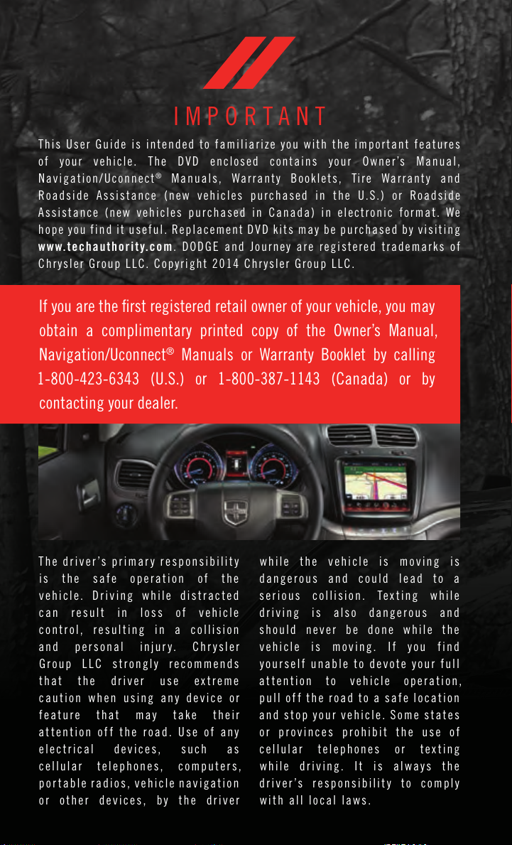
T h e driver ’s p ri ma r y re spons ib il i t y
is the s afe o p eration o f t he
v ehicle . D r i v i ng w hi l e di st rac ted
c an r es ul t i n l os s o f v eh ic le
c o n t r o l, r e su l t ing in a c ol li s i o n
and p e r s o nal inju ry. Chr y s ler
G r o up L LC s tr on gl y r ec omm en ds
that the dr iver us e ex t r eme
c aution when usi ng an y d ev ic e or
f e a ture t hat m ay t a k e t h e i r
a t t e n t ion of f t h e ro ad . U s e of a n y
e le c t r i cal d evice s, s u ch a s
c e llul ar t ele ph ones, c o mputers,
p o r ta bl e r ad io s, vehi cl e nav ig at io n
o r o th er d e v i c e s , b y t h e d ri ver
w hile t he v ehi cl e i s m ov in g i s
dang er ous a nd c ou ld l e ad t o a
s e r i ous c oll is io n. T e x ti n g whil e
driving i s also dan ge rous a nd
should ne ver b e do ne w hi le th e
v ehicle i s m ov in g . I f y o u f in d
y o ur s elf una bl e to d ev ote y our fu ll
a t t e n t ion t o v eh ic le o p e r ation,
pull o ff t he r o a d t o a s a f e l ocati on
and s to p y o ur v eh ic le . S om e s t ates
o r p ro vi nc es p r o h ibit t h e u se o f
c e llul ar t elephone s o r te x t i ng
w hile d ri vi ng . I t i s alw ays t h e
driver ’s respon si bi li ty t o com pl y
with all local laws.
Page 3

TABLE OF CONTENTS
INTRODUCTION/WELCOME
WELCOME FROM CHRYSLER
GROUP LLC ..................2
CONTROLS AT A GLANCE
DRIVER COCKPIT ...............4
INSTRUMENT CLUSTER ...........6
GETTING STARTED
KEY FOB . . . . . . . . . . . . . . . . . . . . . 8
REMOTE STAR T . . . . . . . . . . . . . . . . 9
KEYLESS ENTER-N-GO™ .........10
VEHICLE SECURITY ALARM ........14
SEA T BELT SYSTEMS ............14
SUPPLEMENTAL RESTRAINT SYSTEM (SRS)
—AIRBAGS ................. 15
CHILD RESTRAINTS ............18
HEAD RESTRAINTS .............24
FRONT SEA TS ................27
REAR SEA TS .................30
HEA TED SEATS . . . . . . . . . . . . . . . 32
HEA TED STEERING WHEEL ........33
TIL T/TELESCOPING STEERING
COLUMN ...................34
OPERATING YOUR VEHICLE
ENGINE BREAK-IN
RECOMMENDA TIONS ............35
TURN SIGNAL/WIPER/WASHER/HIGH BEAM
LEVER .....................36
HEADLIGHT SWITCH ............ 37
ELECTRONIC SPEED CONTROL ......38
CLIMA TE CONTROL .............40
PARKVI EW
POWER SUNROOF ..............43
WIND BUFFETING ..............45
®
REAR BACK-UP CAMERA . . 43
ELECTRONICS
YOUR VEHICLE'S SOUND SYSTEM .... 46
IDENTIFYING YOUR RADIO .........48
®
Uconnect
Uconnect
RADIO .....................53
SiriusXM SA TELLITE RADIO .........55
iPod
GARMIN
SiriusXM TRAVEL LINK ...........64
PLAYING iPod
Uconnect
Uconnect
ONL Y) . . . . . . . . . . . . . . . . . . . . . 72
VIDEO ENTERT AINMENT SYSTEM
(VES™) .....................75
STEERING WHEEL AUDIO CONTROLS . . 76
ELECTRONIC VEHICLE INFORMA TION
CENTER (EVIC) ................76
PROGRAMMABLE FEA TURES ....... 77
4.3 & 4.3S A T A GLANCE . . . 49
®
8.4 & 8.4N A T A GLANCE . . . 51
®
/CD/AUX CONTROLS ..........58
®
NAVIGATION ...........60
®
/USB/MP3 DEVICES ....65
®
PHONE .............. 66
®
VOICE COMMAND (8.4 & 8.4N
UNIVERSAL GARAGE DOOR OPENER
(HomeLink
POWER INVERTER .............81
POWER OUTLETS ..............82
®
).................78
UTILITY
TRAILER TOWING WEIGHTS (MAXIMUM
TRAILER WEIGHT RA TINGS) ........84
RECREA TIONAL TOWING (BEHIND
MOTORHOME, ETC.) ............85
WHAT TO DO IN EMERGENCIES
ROADSIDE ASSISTANCE ..........86
INSTRUMENT CLUSTER WARNING
LIGHTS .................... 86
INSTRUMENT CLUSTER INDICA TOR
LIGHTS .................... 91
IF YOUR ENGINE OVERHEA TS .......92
JACKING AND TIRE CHANGING ......93
JUMP-STAR TING ..............101
SHIFT LEVER OVERRIDE .........104
TOWING A DISABLED VEHICLE .....105
FREEING A STUCK VEHICLE .......105
EVENT DA TA RECORDER (EDR) .....106
MAINTAINING YOUR VEHICLE
OPENING THE HOOD ...........107
ENGINE COMPAR TMENT — 2.4L ....108
ENGINE COMPAR TMENT — 3.6L ....110
FLUID CAPACITIES ............112
FLUIDS, LUBRICANTS AND GENUINE
PART S . . . . . . . . . . . . . . . . . . . . 1 12
MAINTENANCE PROCEDURES ......114
MAINTENANCE SCHEDULE ........ 114
MAINTENANCE RECORD ......... 118
FUSES ....................119
TIRE PRESSURES .............122
SPARE TIRES — IF EQUIPPED ......123
WHEEL AND WHEEL TRIM CARE ....124
REPLACEMENT BULBS ..........125
CONSUMER ASSISTANCE
CHRYSLER GROUP LLC CUSTOMER
CENTER ...................126
CHRYSLER CANADA INC. CUSTOMER
CENTER ...................126
ASSISTANCE FOR THE HEARING
IMPAIRED .................. 126
PUBLICA TIONS ORDERING ........ 127
REPORTING SAFETY DEFECTS IN THE
UNITED STATES ..............127
MOPAR® ACCESSORIES
AUTHENTIC ACCESSORIES BY
®
MOPAR
...................128
FREQUENTLY ASKED QUESTIONS
FAQ ’s . . . . . . . . . . . . . . . . . . . . . 12 9
INDEX
.....................130
Page 4

INTRODUCTION/WELCOME
WELCOME FROM CHRYSLER GROUP LLC
Congratulations on selecting your new Chrysler Group LLC vehicle. Be assured that it
represents precision workmanship, distinctive styling, and high quality - all essentials that
are traditional to our vehicles.
Your new Ch rysler Grou p LL C ve hicle h as characteri stics t o en hance t he d river's con trol
under some driving conditions. These are to assist the driver and are never a substitute for
attentive driving. They can never take the driver's place. Always drive carefully.
Your n ew ve hicle has many featu res for the c omfort and conv enience of you and your
passengers. Some of these should not be used when driving because they take your eyes
from the road or your attention from driving. Never text while driving or take your eyes more
than momentarily off the road.
This guide illustrates and describes the operation of features and equipment that are
either standard or optional on this vehicle. This guide may also include a description of
features and equipment that are no longer available or were not ordered on this vehicle.
Please disregard any features and equipment described in this guide that are not available
on this vehicle. Chrysler Group LLC reserves the right to make changes in design and
specifications and/or make additions to or improvements to its products without imposing
any obligation upon itself to install them on products previously manufactured.
This User Guide has been prepared to help you quickly become acquainted with the
important features of your vehicle. It contains most things you will need to operate and
maintain the vehicle, including emergency information.
The DVD includes a computer application containing detailed owner's information which
can be viewed on a personal computer or MAC computer. The multimedia DVD also
includes videos which can be played on any standard DVD player (including the
Uconnect
DVD operational information is located on the back of the DVD sleeve.
For complete owner information, refer to your Owner's Manual on the DVD in the owner’s
kit provided at the time of new vehicle purchase. For your convenience, the information
contained on the DVD may also be printed and saved for future reference.
Chrysler Group LLC is committed to protecting our environment and natural resources. By
converting from paper to electronic delivery for the majority of the user information for
your vehicle, together we greatly reduce the demand for tree-based products and lessen
the stress on our environment.
®
Touc hsc r een Rad ios if equ ipp e d w ith DV D pl ayer ca p abi lit i es) . A ddi t ion a l
VEHICLES SOLD IN CANADA
With respect to any vehicles sold in Canada, the name Chrysler Group LLC shall be
deemed to be deleted and the name Chrysler Canada Inc. used in substitution (excluding
legal lines).
2
Page 5
INTRODUCTION/WELCOME
WARNING!
•Pedalsthatcannotmovefreelycancauselossofvehiclecontrolandincreasethe
risk of serious personal injury.
•Alwaysmakesurethatobjectscannotfallintothedriverfootwellwhilethevehicle
is moving. Objects can become trapped under the brake pedal and accelerator
pedal causing a loss of vehicle control.
•Failuretoproperlyfollowfloormatinstallationormountingcancauseinterference
with the brake pedal and accelerator pedal operation causing loss of control of the
vehicle.
•Neverleavechildrenaloneinavehicle,orwithaccesstoanunlockedvehicle.
Allowing children to be in a vehicle unattended is dangerous for a number of
reasons. A child or others could be seriously or fatally injured. Children should be
warned not to touch the parking brake, brake pedal or the shift lever/transmission
gear selector.
•Donotleavethekeyfobinornearthevehicle,orinalocationaccessibleto
children, and do not leave the ignition of a vehicle equipped with Keyless
Enter-N-Go in the ACC or ON/RUN mode. A child could operate power windows,
other controls, or move the vehicle.
•Neverusethe“PARK”positionasasubstitutefortheparkingbrake.Alwaysapply
the parking brake fully when parked to guard against vehicle movement and
possible injury or damage.
•RefertoyourOwner'sManualontheDVDforfurtherdetails.
USE OF AFTERMARKET PRODUCTS (ELECTRONICS)
The use of aftermarket devices including cell phones, MP3 players, GPS systems, or
chargers may affect the performance of on-board wireless features including Keyless
Enter-N-Go™ and Remote Start range. If you are experiencing difficulties with any of your
wireless features, try disconnecting your aftermarket devices to see if the situation
improves. If your symptoms persist, please see an authorized dealer.
CHRYSLER, DODGE, JEEP, RAM, MOPAR and Uconnect are registered trademarks of
Chrysler Group LLC.
COPYRIGHT ©2014 CHRYSLER GROUP LLC
3
Page 6
CONTROLS AT A GLANCE
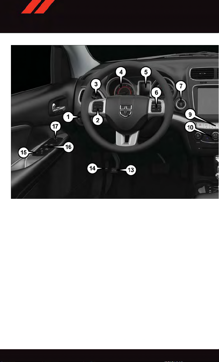
DRIVER COCKPIT
1. Headlight Switch pg. 37
2. Electronic Vehicle Information Center (EVIC) Controls pg. 76
3. Turn Signal/Light Lever pg. 36
4. Instrument Cluster pg. 6
5. Electronic Vehicle Information Center (EVIC) Display pg. 6
6. Speed Controls pg. 38
7. Engine Start/Stop Button pg. 12
8. Your Vehicle's Sound System pg. 46
9. Switch Panel
•HazardSwitch
•RearDefrosterpg.42
•ElectronicStabilityControl(ESC)OFFIndicatorLightpg.91
•AirRecirculationpg.43
4
Page 7
CONTROLS AT A GLANCE
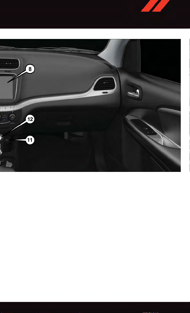
10. Climate Controls pg. 40
11. Power Outlet pg. 82
12. Shifter
13. Emergency Brake Pedal
14. Opening The Hood pg. 107
15. Power Door Locks
16. Power Windows
17. Power Mirror Switch
5
Page 8
CONTROLS AT A GLANCE
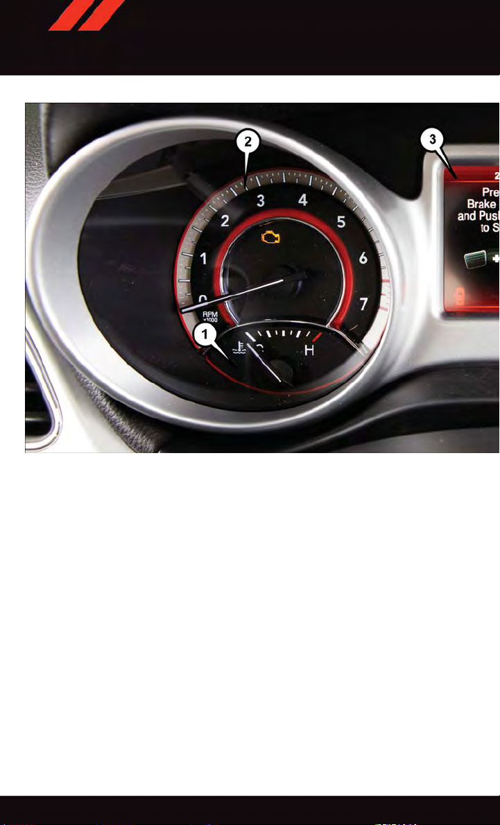
INSTRUMENT CLUSTER
1. Temperature Gauge
2. Tachometer
3. Electronic Vehicle Information Center (EVIC) Display
(See page 86 for Instrument Cluster Warning Light information.)
6
Page 9
CONTROLS AT A GLANCE
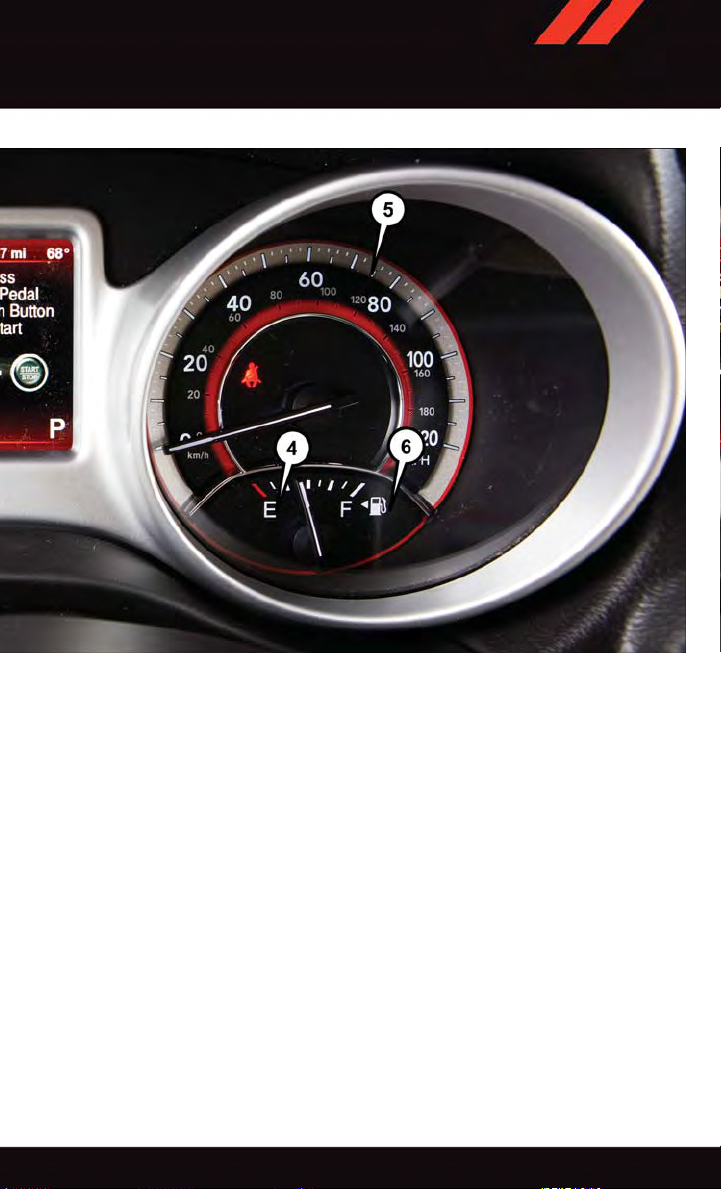
4. Fuel Gauge
5. Speedometer
6. Fuel Filler Door Location
(See page 91 for Instrument Cluster Indicator Lights information.)
7
Page 10
GETTING STARTED
KEY FOB
Locking And Unlocking The Doors And Liftgate
Lock The Doors And Liftgate
Push and release the LOCK button on the
RKE transmitter to lock all doors and liftgate. The turn signal lights will flash, and
the horn will chirp to acknowledge the signal.
Unlock The Doors And Liftgate
Push and release the UNLOCK button on
the RKE transmitter once to unlock the
driver’s door or twice within five seconds to
unlock all doors and liftgate. The turn signal
lights will flash to acknowledge the unlock
signal. The illuminated entry system will
also turn on.
All doors can be programmed to unlock on
the first push of the UNLOCK button. Refer
to “Uconnect
Features” in the this guide for further information.
®
Customer Programmable
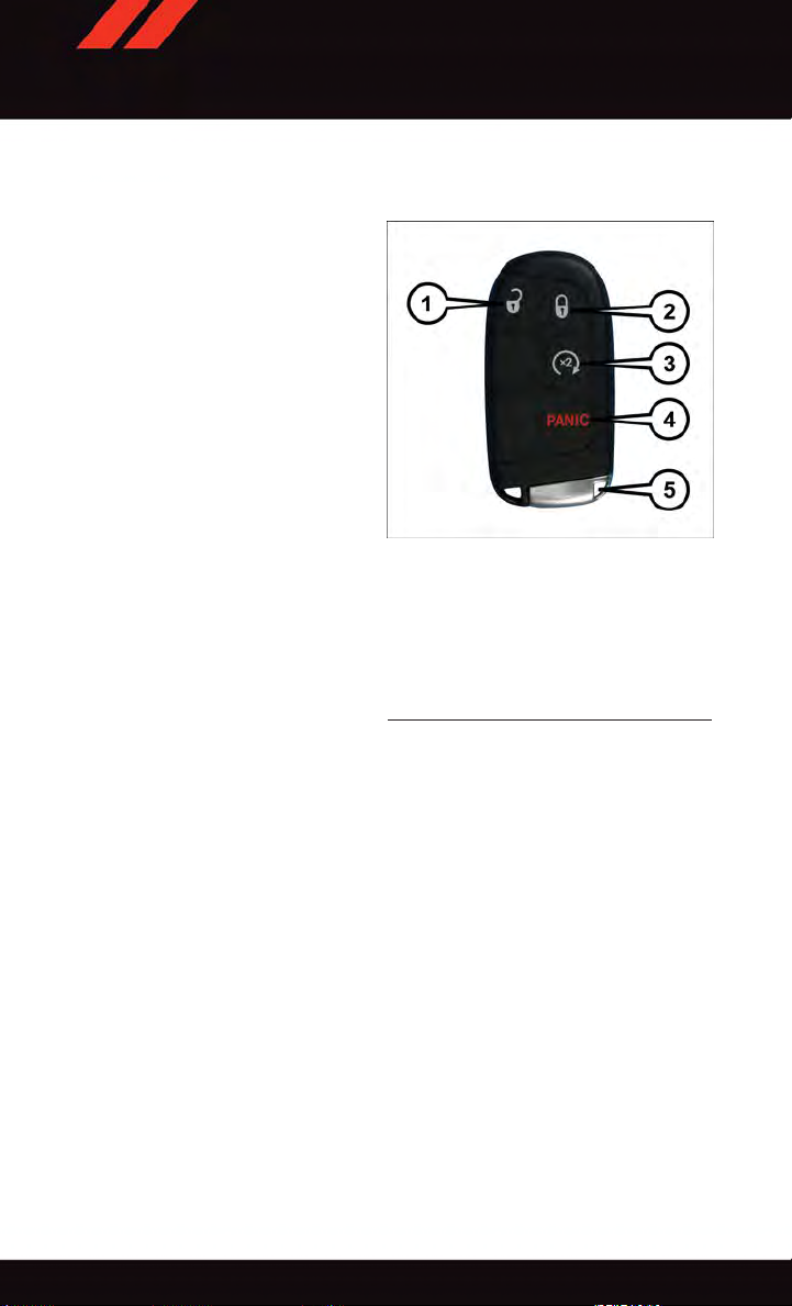
1—Unlock
2—Lock
3—RemoteStart
4—PanicButton
5—EmergencyKey
Key Fob
Panic Alarm
1. Push the PANIC button once to turn the panic alarm on.
2. Wait approximately three seconds and push the button a second time to turn the panic
alarm off.
Emergency Key
Should the battery in the vehicle or the Key Fob transmitter go dead, there is an
emergency key located in the Key Fob. To remove the emergency key, slide the button at
the back of the Key Fob sideways with your thumb and then pull the key out with your
other hand.
8
Page 11
GETTING STARTED
WARNING!
•Whenleavingthevehicle,alwaysremovetheKeyFobfromtheignitionandlock
your vehicle.
•Neverleavechildrenaloneinavehicle,orwithaccesstoanunlockedvehicle.
Allowing children to be in a vehicle unattended is dangerous for a number of
reasons. A child or others could be seriously or fatally injured. Children should be
warned not to touch the parking brake, brake pedal or the transmission gear
selector.
•DonotleavetheKeyFobinornearthevehicle(orinalocationaccessibleto
children), and do not leave the ignition of a vehicle equipped with Keyless
Enter-N-Go™ in the ACC or ON/RUN mode. A child could operate power windows,
other controls, or move the vehicle.
REMOTE START
x
•PushtheREMOTESTARTbutton
Pushing the REMOTE STAR T button a third time shuts the engine off.
•Todrivethevehicle,pushtheUNLOCKbuttonandcycletheignitiontotheON/RUN
position.
•Withremotestart,theenginewillonlyrunfor15minutes(timeout)unlesstheignition
is cycled to the ON/RUN position.
•ThevehiclemustbecycledtotheON/RUNpositionaftertwoconsecutivetimeouts.
2
on the Key Fob twice within five seconds.
WARNING!
•Donotstartorrunanengineinaclosedgarageorconfinedarea.Exhaustgas
contains Carbon Monoxide (CO) which is odorless and colorless. Carbon Monoxide
is poisonous and can cause you or others to be severely injured or killed when
inhaled.
•KeepKeyFobtransmittersawayfromchildren.OperationoftheRemoteStart
System, windows, door locks or other controls could cause you and others to be
severely injured or killed.
9
Page 12
GETTING STARTED
KEYLESS ENTER-N-GO™
The Keyless Enter-N-Go™ system is an enhancement to the vehicle’ s Remote Keyless
Entry (RKE) feature. This feature allows you to lock and unlock the vehicle's door(s) and
liftgate without having to push the Key Fob LOCK or UNLOCK buttons, as well as starting
and stopping the vehicle with the push of a button.
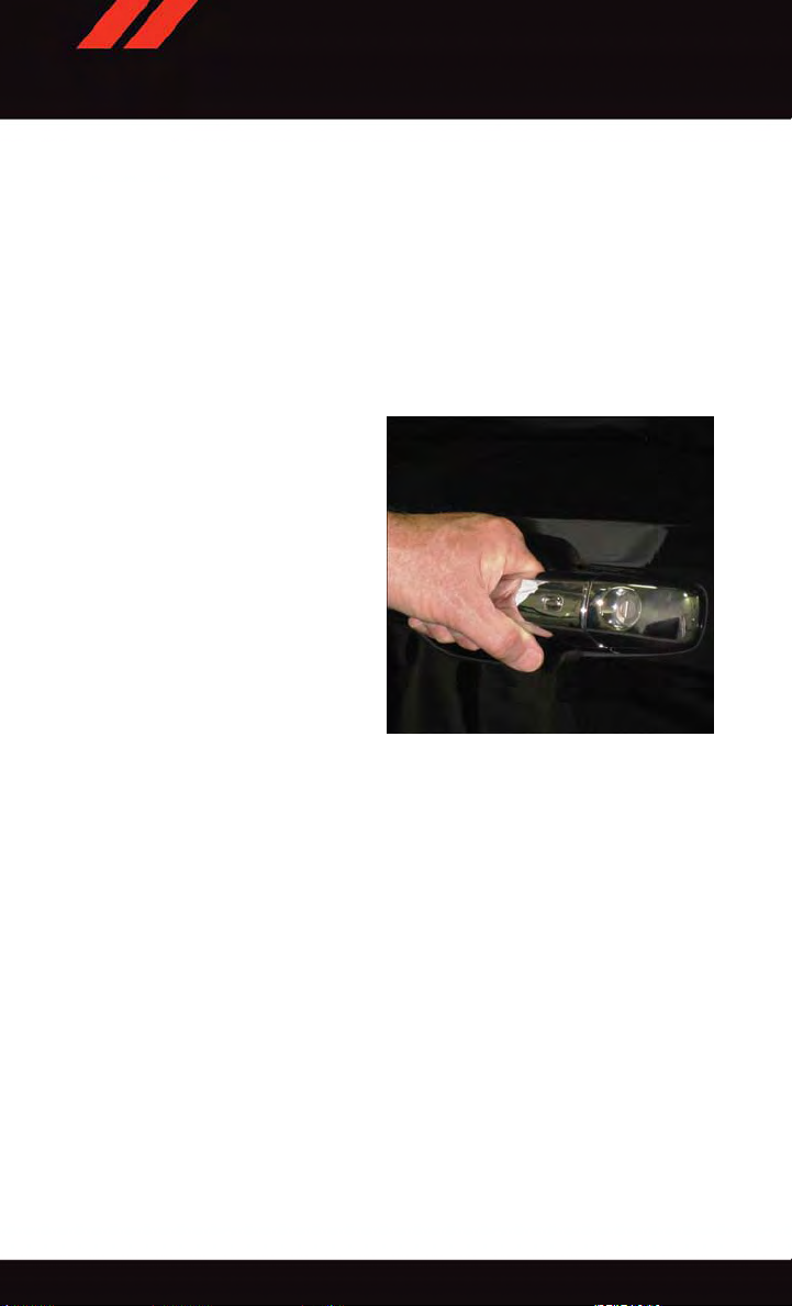
To Unlock From The Driver Or Passenger Side:
•WithavalidKeylessEnter-N-Go™KeyFoblocatedoutsidethevehicleandwithin5ft
(1.5 m) of the driver or passenger side door handle, grab either front door handle to
unlock the door automatically.
Grab The Door Handle To Unlock
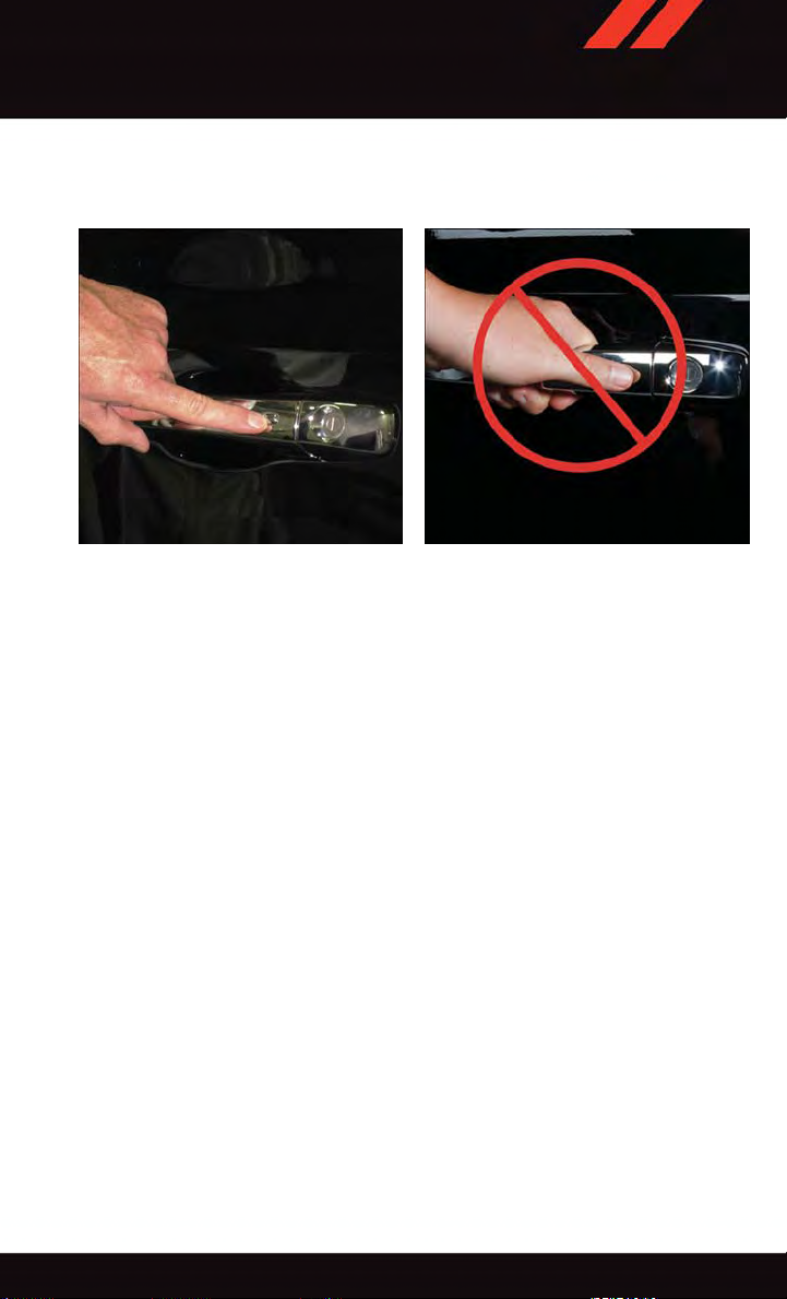
To Lock The Vehicle:
•Bothfrontdoorhandleshavebuttonslocatedontheoutsideofthehandle.Withoneof
the vehicle’s Keyless Enter-N-Go™ Key Fobs located outside the vehicle and within 5
ft (1.5m) of the driver's or passenger front door handle, push the door handle button to
lock all four doors and liftgate.
10
Page 13
GETTING STARTED
•DoNOTgrabthedoorhandlewhenpushingthedoorhandlelockbutton.Thiscould
unlock the door(s).
Push The Door Handle Button To Lock Do NOT Grab The Handle When Locking
NOTE:
•If“UnlockAllDoors1stPress”isprogrammed,alldoorswillunlockwhenyougrabhold
of the front driver's door handle. T o select between “Unlock Driver Door 1st Press” and
“Unlock All Doors 1st Press,” refer to the “Uconnect
Owner's Manual on the DVD or “Programmable Features” in this guide for further
information.
•If“UnlockAllDoors1stPress”isprogrammed,alldoorsandliftgatewillunlockwhen
you push the liftgate button. If “Unlock Driver Door 1st Press” is programmed, only the
liftgate will unlock when you push the liftgate button. T o select between “Unlock Driver
Door 1st Press” and “Unlock All Doors 1st Press,” refer to the “Uconnect
your vehicle's Owner's Manual on the DVD or “Programmable Features” in this guide for
further information.
•IfaKeyFobisdetectedinthevehiclewhenlockingthevehicleusingthepowerdoor
lock switch, the doors and liftgate will unlock and the horn will chirp three times. On the
third attempt, your Key Fob can be locked inside the vehicle.
•AfterpushingtheKeylessEnter-N-Go™LOCKbutton,youmustwaittwoseconds
before you can lock or unlock the vehicle using the door handle. This is done to allow
you to check if the vehicle is locked by pulling the door handle without the vehicle
reacting and unlocking.
®
Settings” in your vehicle’s
®
Settings” in
11
Page 14
GETTING STARTED
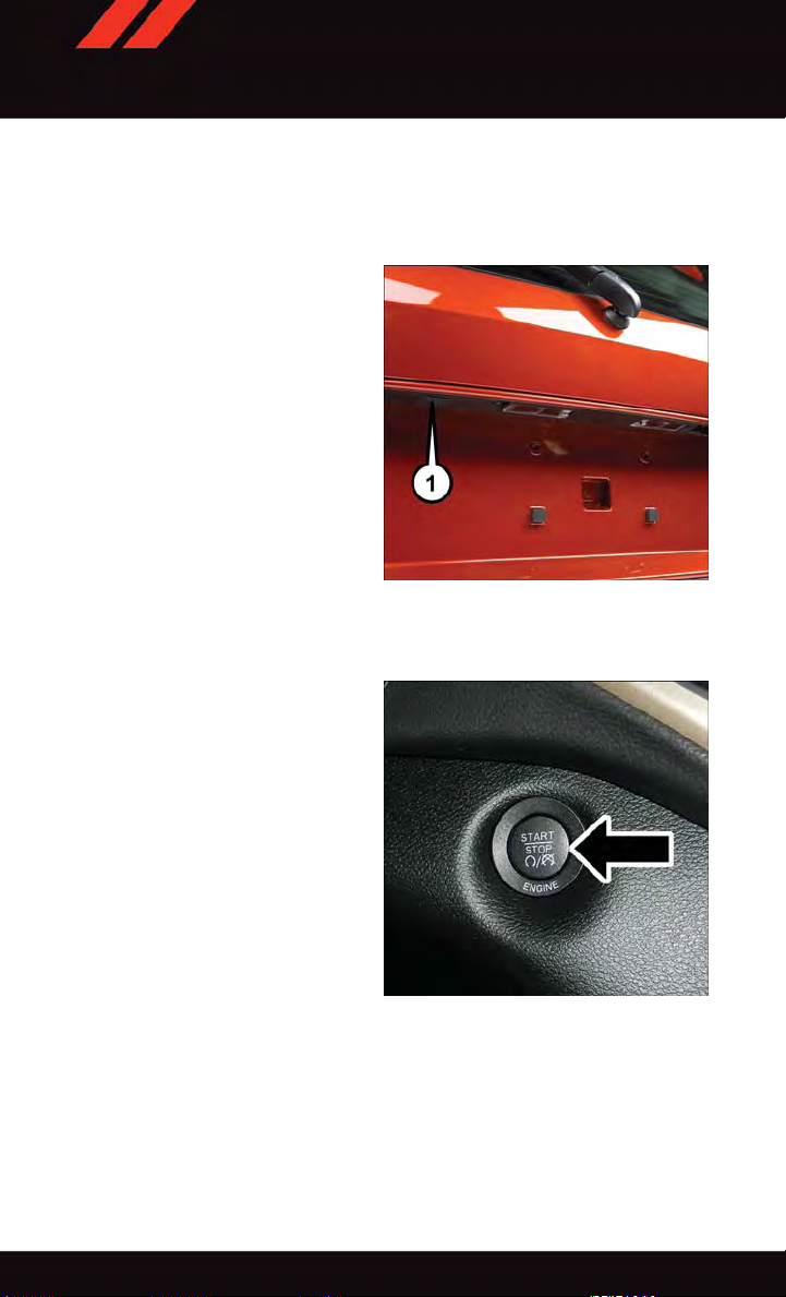
Lock Or Unlock The Liftgate:
•WithavalidKeylessEnter-N-Go™KeyFobwithin3feet(1meter)oftheliftgate,push
the electronic liftgate lock/unlock pad located to the left of the liftgate handle to unlock
the liftgate. Push the button a second time to lock the liftgate.
NOTE:
Refer to your Owner's Manual on the DVD
for further information.
1 — Electronic Liftgate Lock/Unlock Pad
ENGINE STARTING/STOPPING
Starting
•WithavalidKeylessEnter-N-Go™Key
Fob inside the vehicle.
Place the shift lever in PARK or NEUTRAL.
•
•
While pushing the brake pedal, push the
ENGINE START/STOP button once. If the
engine fails to start, the starter will disengage automatically after 10 seconds.
•
To s t op the cra n kin g of th e en g ine pr i or t o
the engine starting, push the button again.
NOTE:
In case the ignition switch does not change
with the push of a button, the RKE transmitter (Key Fob) may have a low or dead
battery. In this situation, a back up method
can be used to operate the ignition switch. Put the nose side of the Key Fob against the
ENGINE START/STOP button and push to operate the ignition switch.
Engine Start/Stop Button
12
Page 15
GETTING STARTED
Stopping
•PlacetheshiftleverinPARK.
•PushtheENGINESTART/STOPbuttononce.TheignitionswitchwillreturntotheOFF
position.
If the shift lever is not in PARK, the ENGINE START/STOP button must be held for two seconds
•
and vehicle speed must be above 5 MPH (8 km/h) before the engine will shut off.
Accessory Positions With Engine Off
NOTE:
The following functions are with the driver’s foot OFF the Brake Pedal (Transmission in
PARK o r NEUTRAL P osition).
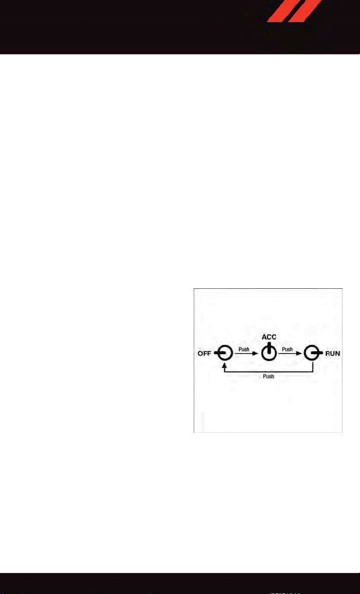
Starting With The Ignition Switch In The OFF Position:
•PushtheENGINESTART/STOPbuttononcetochangetheignitionswitchtotheACC
position.
•PushtheENGINESTART/STOPbuttonasecondtimetochangetheignitionswitchto
the ON/RUN position.
•PushtheENGINESTART/STOPbuttonathirdtimetoreturntheignitionswitchtothe
OFF position.
NOTE:
If the ignition switch is left in the ACC or
ON/RUN (engine not running) position and
the transmission is in PARK, the system will
automatically time out after 30 minutes of
inactivity and the ignition will switch to the
OFF position.
•Incasetheignitionswitchdoesnot
change with the push of a button, the
RKE transmitter (Key Fob) may have a
low or dead battery. In this situation, a
back up method can be used to operate
the ignition switch. Put the nose side
(side opposite of the emergency key) of
the Key Fob against the ENGINE ST ART/
STOP button and push to operate the
ignition switch.
Ignition Positions
13
Page 16

GETTING STARTED
VEHICLE SECURITY ALARM
The Vehicle Security Alarm monitors the vehicle doors for unauthorized entry and the
Keyless Enter-N-Go™ START/STOP button for unauthorized operation. While the Vehicle
Security Alarm is armed, interior switches for door locks and decklid release are disabled.
If something triggers the alarm, the Vehicle Security Alarm will provide the following
audible and visible signals: the horn will pulse, the park lamps and/or turn signals will
flash, and the Vehicle Security Light in the instrument cluster will flash.
To Arm:
•PushtheKeylessEnter-N-Go™START/STOPbuttonuntiltheElectronicVehicle
Information Center (EVIC) indicates that the vehicle ignition is “OFF.” Push the power
door lock switch while the door is open, push the Key Fob LOCK button, or with one of
the Key Fobs located outside the vehicle and within 5 ft (1.5 m) of the driver's and
passenger front door handles, push the Keyless Enter-N-Go™ LOCK button located on
the door handle.
NOTE:
After pushing the Keyless Enter-N-Go™ LOCK button, you must wait two seconds before
you can lock or unlock the vehicle via the door handle.
To Disarm:
•PushtheKeyFobUNLOCKbuttonorwithoneoftheKeyFobslocatedoutsidethe
vehicle and within 5 ft (1.5 m) of the driver's and passenger front door handles, grab the
Keyless Enter-N-Go™ door handle and enter the vehicle, then push the Keyless
Enter-N-Go™ ST ART/STOP button (requires at least one valid Key Fob in the vehicle).
SEAT BELT SYSTEMS
Lap/Shoulder Belts
•Allseatingpositionsinyourvehicleareequippedwithlap/shoulderbelts.
•Besureeveryoneinyourvehicleisinaseatandusingaseatbeltproperly.
•Positionthelapbeltsothatitissnugandlieslowacrossyourhips,belowyour
abdomen. To remove slack in the lap belt portion, pull up on the shoulder belt. To loosen
the lap belt if it is too tight, tilt the latch plate and pull on the lap belt. A snug seat belt
reduces the risk of sliding under the seat belt in a collision.
•Positiontheshoulderbeltacrosstheshoulderandchestwithminimal,ifanyslackso
that it is comfortable and not resting on your neck. The retractor will withdraw any slack
in the shoulder belt.
Seat Belt Pretensioner
•Thefrontseatbeltsystemisequippedwithpretensioningdevicesthataredesignedto
remove slack from the seat belt in the event of a collision.
•Adeployedpretensioneroradeployedairbagmustbereplacedimmediately.
14
Page 17
GETTING STARTED
WARNING!
•Inacollision,youandyourpassengerscansuffermuchgreaterinjuriesifyouare
not properly buckled up. You can strike the interior of your vehicle or other
passengers, or you can be thrown out of the vehicle. Always be sure you and others
in your vehicle are buckled up properly.
•Ashoulderbeltplacedbehindyouwillnotprotectyoufrominjuryduringacollision.
You are more likely t o hit y our h ead i n a co llision i f you d o no t wear your s houlder
belt. The lap and shoulder belt are meant to be used together.
•Aseatbeltthatistooloosewillnotprotectyouproperly.Inasuddenstop,youcould
move too far forward, increasing the possibility of injury. Wear your seat belt snugly.
•Afrayedortornseatbeltcouldripapartinacollisionandleaveyouwithno
protection. Inspect the seat belt system periodically, checking for cuts, frays, or
loose parts. Damaged parts must be replaced immediately . Do not disassemble or
modify the system. Seat belt assemblies must be replaced after a collision.
SUPPLEMENTAL RESTRAINT SYSTEM (SRS) — AIR BAGS
Air Bag System Components
Your v ehicle ma y be e quipped w ith t he follow ing a ir bag syst em componen ts:
•OccupantRestraintController(ORC)
•AirBagWarningLight
•SteeringWheelandColumn
•InstrumentPanel
•KneeImpactBolsters
•AdvancedFrontAirBags
•SupplementalSideAirBags
•SupplementalKneeAirBags
•FrontandSideImpactSensors
•SeatBeltPretenioners
•SeatBeltBuckleSwitch
•SeatTrackPositionSensors
15
Page 18

GETTING STARTED
Advanced Front Air Bags
•ThisvehiclehasAdvancedFrontAirBagsforboththedriverandfrontpassengerasa
supplement to the seat belt restraint systems. The Advanced Front Air Bags will not
deploy in every type of collision.
•AdvancedFrontAirBagsaredesignedtoprovideadditionalprotectionbysupplementing the seat belts. Advanced Front Air Bags are not expected to reduce the risk of injury
in rear, side, or rollover collisions.
•TheAdvancedFrontAirBagswillnotdeployinallfrontalcollisions,includingsome
that may produce substantial vehicle damage — for example, some pole collisions,
truck underrides, and angle offset collisions.
•Ontheotherhand,dependingonthetypeandlocationofimpact,AdvancedFrontAir
Bags may deploy in crashes with little vehicle front-end damage but that produce a
severe initial deceleration.
•Becauseairbagsensorsmeasurevehicledecelerationovertime,vehiclespeedand
damage by themselves are not good indicators of whether or not an air bag should have
deployed.
•Seatbeltsarenecessaryforyourprotectioninallcollisions,andalsoareneededtohelp
keep you in position, away from an inflating air bag.
•Theairbagsmustbereadytoinflateforyourprotectioninacollision.TheOccupant
Restraint Controller (ORC) monitors the internal circuits and interconnecting wiring
associated with air bag system electrical components.
•TheORCturnsontheAirBagWarningLightintheinstrumentpanelforapproximately
four to eight seconds for a self-check when the ignition switch is first turned to the
ON/RUN position. After the self-check, the Air Bag Warning Light will turn off. If the
ORC detects a malfunction in any part of the system, it turns on the Air Bag Warning
Light, either momentarily or continuously. A single chime will sound to alert you if the
light comes on again after initial startup.
•TheORCmonitorsthereadinessoftheelectronicpartsoftheairbagsystemwhenever
the ignition switch is in the START or ON/RUN position. If the ignition switch is in the
OFF position or in the ACC position, the air bag system is not on and the air bags will
not inflate.
•IftheAirBagWarningLightintheinstrumentpanelisnotonduringthefourtoeight
seconds when the ignition switch is first turned to the ON/RUN position, stays on, or
turns on while driving, have the vehicle serviced by an authorized service center
immediately.
NOTE:
If the speedometer, tachometer, or any engine related gauges are not working, the
Occupant Restraint Controller (ORC) may also be disabled. In this condition the air bags
may not be ready to inflate for your protection. Have an authorized dealer service the air
bag system immediately.
16
Page 19
GETTING STARTED
•Afteranycollision,thevehicleshouldbetakentoanauthorizeddealerimmediately.
•Donotdriveyourvehicleaftertheairbagshavedeployed.Ifyouareinvolvedinanother
collision, the air bags will not be in place to protect you.
•Ifitisnecessarytomodifytheairbagsystemforpersonswithdisabilities,contactyour
authorized dealer.
•RefertotheOwner'sManualontheDVDregardingtheSupplementalRestraintSystem
(SRS) for further details.
Supplemental Knee Air Bags
This vehicle is equipped with a Supplemental Driver Knee Air Bag mounted in the
instrument panel below the steering column. The Supplemental Driver Knee Air Bag
provides enhanced protection during a frontal impact by working together with the seat
belts, pretensioners, and Advanced Front Air Bags.
WARNING!
•Relyingontheairbagsalonecouldleadtomoresevereinjuriesinacollision.The
air bags work with your seat belt to restrain you properly. In some collisions, the air
bags won't deploy at all. Always wear your seat belts even though you have air bags.
•BeingtooclosetothesteeringwheelorinstrumentpanelduringAdvancedFrontAir
Bag deployment could cause serious injury, including death. Air bags need room to
inflate. Sit back, comfortably extending your arms to reach the steering wheel or
instrument panel.
•Noobjectsshouldbeplacedoverorneartheairbagontheinstrumentpanelor
steering wheel because any such objects could cause harm if the vehicle is in a
collision severe enough to cause the air bag to inflate.
Supplemental Side Air Bags
•ThisvehicleisequippedwithSupplementalSeat-MountedSideAirBags(SABs)
located in the outboard side of the front seats. The SABs are marked with a SRS
AIRBAG or AIRBAG label sewn into the outboard side of the seats.
•ThisvehicleisequippedwithSupplementalSideAirBagInflatableCurtains(SABICs)
located above the side windows. The trim covering the SABICs is labeled SRS AIRBAG
or AIRBAG. The SABICs may help reduce the risk of partial or complete ejection of
vehicle occupants through side windows in certain side impact events.
•TheSABICsandSABs(“SideAirBags”)aredesignedtoactivateincertainside
impacts and certain rollover events. The Occupant Restraint Controller (“ORC”)
determines whether the deployment of the Side Air Bags in a particular side impact or
rollover event is appropriate, based on the severity and type of collision. Vehicle damage
by itself is not a good indicator of whether or not Side Air Bags should have deployed.
17
Page 20

GETTING STARTED
WARNING!
•SideAirBagsneedroomtoinflate.Donotleanagainstthedoororwindow.Sit
upright in the center of the seat.
•BeingtooclosetotheSideAirBagsduringdeploymentcouldcauseyoutobe
severely injured or killed.
•RelyingontheSideAirBagsalonecouldleadtomoresevereinjuriesinacollision.
The Side Air Bags work with your seat belt to restrain you properly. In some
collisions, Side Air Bags won’t deploy at all. Always wear your seat belt even though
you have Side Air Bags.
•
This vehicle is equipped with left and right Supplemental Side Air Bag Inflatable
Curtains (SABICs). Do not stack luggage or other cargo up high enough to block the
deployment of the SABICs. The trim covering above the side windows where the SABIC
and its deployment path are located should remain free from any obstructions.
•ThisvehicleisequippedwithSABICs.InorderfortheSABICstoworkasintended,
do not install any accessory items in your vehicle which could alter the roof. Do not
add an aftermarket sunroof to your vehicle. Do not add roof racks that require
permanent attachments (bolts or screws) for installation on the vehicle roof. Do not
drill into the roof of the vehicle for any reason.
•DonotuseaccessoryseatcoversorplaceobjectsbetweenyouandtheSideAir
Bags; the performance could be adversely affected and/or objects could be pushed
into you, causing serious injury.
CHILD RESTRAINTS
Children 12 years or younger should ride properly buckled up in a rear seat, if available.
According to crash statistics, children are safer when properly restrained in the rear seats
rather than in the front.
Every state in the United States and all Canadian provinces require that small children
ride in proper restraint systems. This is the law, and you can be prosecuted for ignoring it.
NOTE:
•Foradditionalinformation,refertowww.Seatcheck.orgorcall1-866-SEATCHECK.
•
Canadian residents should refer to Transport Canada’s website for additional information:
http://www.tc.gc.ca/eng/motorvehiclesafety/safedrivers-childsafety-index-53.htm
LATCH — Lower Anchors And Tethers For CHildren
Your v ehicle is equipped with the chil d r estraint anchora ge system c alled LATCH, which
stands for Lower Anchors and Tethers for CHildren.
The second row seating positions have lower anchors and top tether anchors. The third row
seating positions (if equipped) do not have lower anchors or top tether anchors.
18
Page 21
GETTING STARTED
LATCH System Weight Limit
You may use th e LATCH anchor age system until the combin ed weight of the child and the
child restraint is 65 lbs (29.5 kg). Use the seat belt and tether anchor instead of the
LA TCH system once the combined weight is more than 65 lbs (29.5 kg).
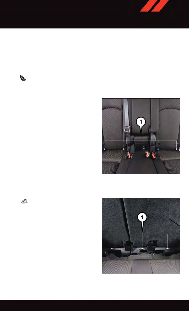
Locating LATCH Anchorages
The lower anchorages are round bars that are found at the rear of the seat cushion
where it meets the seatback. They are just visible when you lean into the rear seat to install
the child restraint. You will easily feel them if you run your finger along the gap between
the seatback and seat cushion.
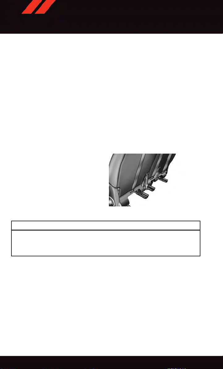
Locating Tether Anchorages
In addition, there are tether strap
anchors located behind each second row
seatback, near the floor.
1 — Lower Anchors
1 — Tether Anchorages
19
Page 22
GETTING STARTED
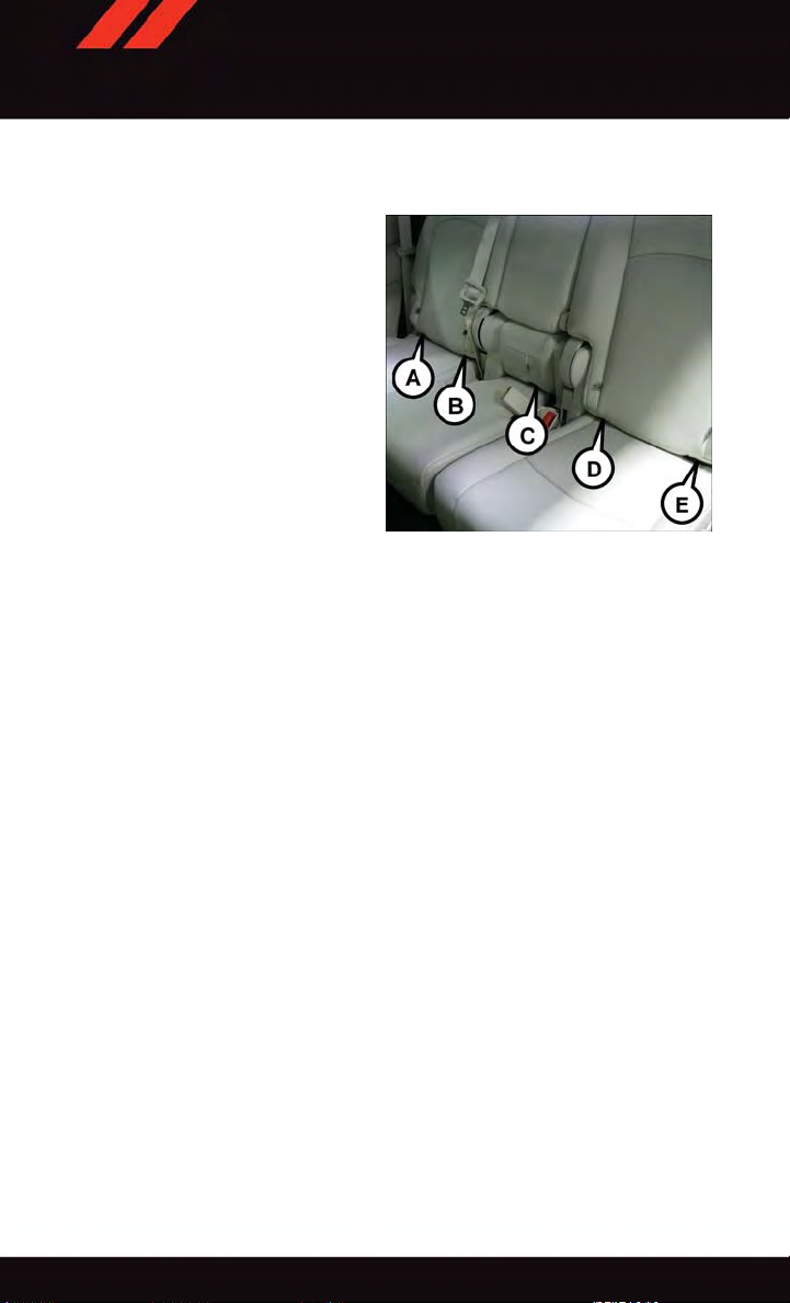
Center Seat LATCH
The center seating position in this vehicle
has a single dedicated anchorage. Use anchorages B and C to install a child seat in
the center position. Do not use anchorages
CandDtoinstallachildseat.Ifyouare
installing three child restraints, you must
use the seatbelt to install the center child
restraint. You can use either the LATCH
anchors or the vehicle’ s seat belt for installing the child seats in the outboard positions. See the vehicle owner’s manual for
more information about center LATCH.
Lower Anchors
Installing The Child Restraint Using The LATCH Lower Anchors
NOTE:
Never “share” a LA TCH anchorage with two or more child restraints.
1. Loosen the adjusters on the lower straps and on the tether strap of the child seat so that
you can more easily attach the hooks or connectors to the vehicle anchorages.
2. Attach the lower hooks or connectors of the child restraint to the lower anchorages in
the selected seating position.
3. If the child restraint has a tether strap, connect it to the top tether anchorage. See
below for directions to attach a tether anchor.
4. Tighten all of the straps as you push the child restraint rearward and downward into the
seat. Remove slack in the straps according to the child restraint manufacturer’s
instructions.
5. Test that the child restraint is installed tightly by pulling back and forth on the child
seat at the belt path. It should not move more than 1 inch (25.4 mm) in any direction.
Installing The Child Restraint Using The Vehicle Seat Belts
The seat belts in the outboard passenger seating positions are equipped with a Switchable
Automatic Locking Retractor (ALR). The center seating positions are equipped with a
cinching latch plate. Both types of seat belts are designed to keep the lap portion of the
seat belt tight around the child restraint. Any seat belt system will loosen with time, so
check the belt occasionally, and pull it tight if necessary.
20
Page 23

GETTING STARTED
Tether Anchorage Weight Limit
Always use the tether anchor when using the seat belt to install a forward facing child
restraint, up to the recommended weight limit of the child restraint.
To Install A Child Seat Using An ALR:
1. Pull enough of the seat belt webbing from the retractor to pass it through the belt path
of the child restraint. Do not twist the belt webbing in the belt path.
2. Slide the latch plate into the buckle until you hear a “click.”
3. Pull on the webbing to make the lap portion tight against the child seat.
4. To lock the seat belt, pull down on the shoulder part of the belt until you have pulled
all the seat belt webbing out of the retractor. Then, allow the webbing to retract back
into the retractor. As the webbing retracts, you will hear a clicking sound. This means
the seat belt is now in the Automatic Locking mode.
5. Try to pull the webbing out of the retractor . If it is locked, you should not be able to pull
out any webbing. If the retractor is not locked, repeat the last step.
6. Finally, pull up on any extra webbing to tighten the lap portion around the child
restraint while you push the child restraint rearward and downward into the vehicle
seat.
7. If the child restraint has a top tether strap and the seating position has a top tether
anchorage, connect the tether strap to the anchorage and tighten the tether strap. See
below for directions to attach a tether anchor.
8. Test that the child restraint is installed tightly by pulling back and forth on the child
seat at the belt path. It should not move more than 1 inch (25.4 mm) in any direction.
To Install A Child Seat Using A Cinching Latch Plate:
1. Place the child seat in the center of the seating position.
2. Next, pull enough of the seat belt webbing from the retractor to pass it through the belt
path of the child restraint. Do not twist the belt webbing in the belt path.
3. Slide the latch plate into the buckle until you hear a “click.”
4. Finally, pull up on any excess webbing to tighten the lap portion around the child
restraint while you push the child restraint rearward and downward into the vehicle
seat.
5. If the child restraint has a top tether strap and the seating position has a top tether
anchorage, connect the tether strap to the anchorage and tighten the tether strap. See
below for directions to attach a tether anchor.
6. Test that the child restraint is installed tightly by pulling back and forth on the child
seat at the belt path. It should not move more than 1 inch (25.4 mm) in any direction.
21
Page 24
GETTING STARTED
Installing The Top Tether Strap (With Either Lower Anchors Or Vehicle Seat Belt):
When installing a forward-facing child restraint, always secure the top tether strap, up to
the tether anchor weight limit, whether the child restraint is installed with the lower
anchors or the vehicle seat belt.
Tether Anchorage Installation
1. Route the tether strap to provide the most direct path for the strap between the anchor
and the child seat.
2. If your vehicle is equipped with adjustable rear head restraints, raise the head
restraint, and where possible, route the tether strap under the head restraint and
between the two posts. If not possible, lower the head restraint and pass the tether
strap around the outboard side of the head restraint.
3. Attach the tether strap hook of the child restraint to the top tether anchorage and
remove slack in the tether strap according to the child restraint manufacturer’s
instructions.
Rear Seat Tether Strap Mounting
WARNING!
Securely lock the seat cushion into position before using the seat. Otherwise, the seat
will not provide the proper stability for child seats and/or passengers. An improperly
latched seat cushion could cause serious injury.
22
Page 25
GETTING STARTED
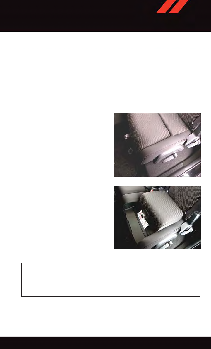
Integrated Child Booster Seat — If Equipped
The Integrated Child Booster Seat is located in each outboard second-row passenger seat.
Refer to the Integrated Child Booster Seat information label located on the front lower
panel of the opened Booster Seat for child height and weight specifications.
To p osi t ion a chi ld int o th e I nte g rat ed Chil d B oos t er Sea t f o llo w t hes e s t eps :
1. Slide the second row seat to the full rear position to use the Integrated Child Booster
Seat. NOTE: The second row bench with Integrated Child Booster Seat must remain in
the full rear position during use.
2. Pull the release loop forward to release the latch and seat cushion.
3. Lift the seat cushion up and push back
to lock it in the booster seat position.
4. Place the child upright in the seat with
their back firmly against the seatback.
5. Grasp the latch plate and pull out the
seat belt.
6. Slide the latch plate up the webbing as
far as necessary to allow the seat belt to
go around the child’ s lap. NOTE: The lap
portion of the seat belt should be low on
the hips and as snug as possible.
7. Once the seat belt is long enough to fit
properly, insert the latch plate into the
buckle until you hear a “click.”
8. To remove the slack from the lap belt,
pull upward on the shoulder portion of
the seat belt.
9. To release the seat belt, push the red
button on the buckle.
Pull The Booster Seat Release Loop
Booster Seat Locked In Position
WARNING!
Securely lock the seat cushion into position before using the seat. Otherwise, the seat
will not provide the proper stability for child seats and/or passengers. An improperly
latched seat cushion could cause serious injury.
23
Page 26

GETTING STARTED
WARNING!
•Inacollision,anunrestrainedchild,evenatinybaby,canbecomeaprojectile
inside the vehicle. The force required to hold even an infant on your lap could
become so great that you could not hold the child, no matter how strong you are.
The child and others could be severely injured or killed. Any child riding in your
vehicle should be in a proper restraint for the child's size.
•Rearward-facingchildseatsmustneverbeusedinthefrontseatofavehiclewith
afrontpassengerairbag.Anairbagdeploymentcouldcausesevereinjuryordeath
to infants in this position.
•Onlyusearearward-facingchildrestraintinavehiclewitharearseat.
•
Improper installation of a child restraint to the LA TCH anchorages can lead to failure of
an infant or child restraint. The child could be severely injured or killed. Follow the
manufacturer’s directions exactly when installing an infant or child restraint.
•Anincorrectlyanchoredtetherstrapcouldleadtoincreasedheadmotionand
possible injury to the child. Use only the anchor positions directly behind the child
seat to secure a child restraint top tether strap.
•Ifyourvehicleisequippedwithasplitrearseat,makesurethetetherstrapdoesnot
slip into the opening between the seatbacks as you remove slack in the strap.
HEAD RESTRAINTS
Head restraints are designed to reduce the risk of injury by restricting head movement in
the event of a rear impact. Head restraints should be adjusted so that the top of the head
restraint is located above the top of your ear.
WARNING!
The head restraints for all occupants must be properly adjusted prior to operating the
vehicle or occupying a seat. Head restraints should never be adjusted while the vehicle
is in motion. Driving a vehicle with the head restraints improperly adjusted or removed
could cause serious injury or death in the event of a collision.
Active Head Restraints (AHR) — Front Seats
Active Head Restraints are passive, deployable components, and vehicles with this
equipment can not be readily identified by any markings, only through visual inspection
of the head restraint. The head restraint will be split in two halves, with the front half being
soft foam and trim, the back half being decorative plastic.
When AHRs deploy during a rear impact, the front half of the head restraint extends
forward to minimize the gap between the back of the occupant’s head and the AHR. This
system is designed to help prevent or reduce the extent of injuries to the driver and front
passenger in certain types of rear impacts. Refer to “Occupant Restraints” in “Things To
Know Before Starting” in the Owner's Manual on the DVD for further information.
24
Page 27
GETTING STARTED
To rai se t h e h e ad r est r ain t , p u ll u pwa r d on t he h ead r est rai n t. To l owe r t he h ead r e str ain t ,
push the adjustment button, located at the base of the head restraint, and push downward
on the head restraint.
For comfort, the Active Head Restraints can be tilted forward and backward. To tilt the
head restraint closer to the back of your head, pull forward on the bottom of the head
restraint. Push rearward on the bottom of the head restraint to move the head restraint
away from your head.
NOTE:
•Theheadrestraintsshouldonlyberemovedbyqualifiedtechnicians,forservice
purposes only. If either of the head restraints require removal, see your authorized
dealer.
•IntheeventofdeploymentofanActiveHeadRestraint,referto“OccupantRestraints/
Supplemental Active Head Restraints (AHR)/Resetting Active Head Restraints (AHR)”
in “Things To Know Before Starting” in the Owner's Manual on the DVD for further
information.
WARNING!
•DonotplaceitemsoverthetopoftheActiveHeadRestraint,suchascoats,seat
covers or portable DVD players. These items may interfere with the operation of the
Active Head Restraint in the event of a collision and could result in serious injury or
death.
•ActiveHeadRestraintsmaybedeployediftheyarestruckbyanobjectsuchasa
hand, foot or loose cargo. T o avoid accidental deployment of the Active Head
Restraint ensure that all cargo is secured, as loose cargo could contact the Active
Head Restraint during sudden stops. Failure to follow this warning could cause
personal injury if the Active Head Restraint is deployed.
Head Restraints — Second Row Seats
The second row seats are equipped with adjustable and removable head restraints. To
raise the head restraint, pull upward on the head restraint. To lower the head restraint,
push the adjustment button located on the base of the head restraint, and push downward
on the head restraint.
WARNING!
Alooseheadrestraintthrownforwardinacollisionorhardstopcouldcauseserious
injury or death to occupants of the vehicle. Always securely stow removed head
restraints in a location outside the occupant compartment.
To rem o ve t h e h ead r e str ain t , push t h e adj u stm ent an d t he rel eas e b utt o ns w h ile pu lli n g
upward on the whole assembly and raise it up as far as it can go. To reinstall the headrest,
put the headrest posts into the holes while pushing the release buttons. Then adjust it to
the appropriate height.
25
Page 28
GETTING STARTED
WARNING!
ALL the head restraints MUST be reinstalled in the vehicle to properly protect the
occupants. Follow the re-installation instructions above prior to operating the vehicle or
occupying a seat.
NOTE:
For proper routing of a Child Seat Tether , refer to “Occupant Restraints” in “Things T o
Know Before Starting” in the Owner's Manual on the DVD for further information.
WARNING!
Driving a vehicle with the head restraints removed or improperly adjusted could cause
serious injury or death in the event of a collision. The head restraints should be checked
prior to operating the vehicle and never adjusted while the vehicle is in motion.
Third Row Passenger Seats — Seven Passenger Models
These head restraints are non-adjustable and non-removable. However, you can fold them
forward when they are not in use by passengers. Refer to “50/50 Split Third-Row
Passenger Seats With Fold-Flat Feature — Seven Passenger Models” in the Owner's
Manual on the DVD for further information.
WARNING!
Do not allow a passenger to sit in a third row seat without having the head restraint
unfolded and locked in place. Failure to follow this warning may result in personal
injury to the passenger in the event of a collision.
26
Page 29
GETTING STARTED
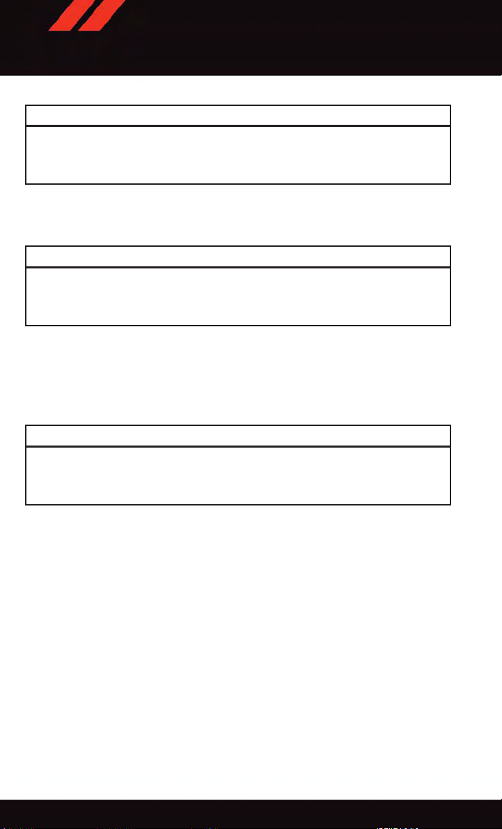
FRONT SEATS
Power Seats
•Thepowerseatswitch,locatedonthe
outboard side of the seat near the floor,
controls forward/back, up/down, and tilt
adjustment.
Power Seat
1—PowerSeatSwitch
2—ReclinerLever
Power Lumbar
•Pushtheswitchforwardtoincreasethe
lumbar support. Push the switch rearward to decrease the lumbar support.
•Pushingupwardordownwardonthe
switch will raise and lower the position of
the support.
Power Lumbar Switch
27
Page 30
GETTING STARTED
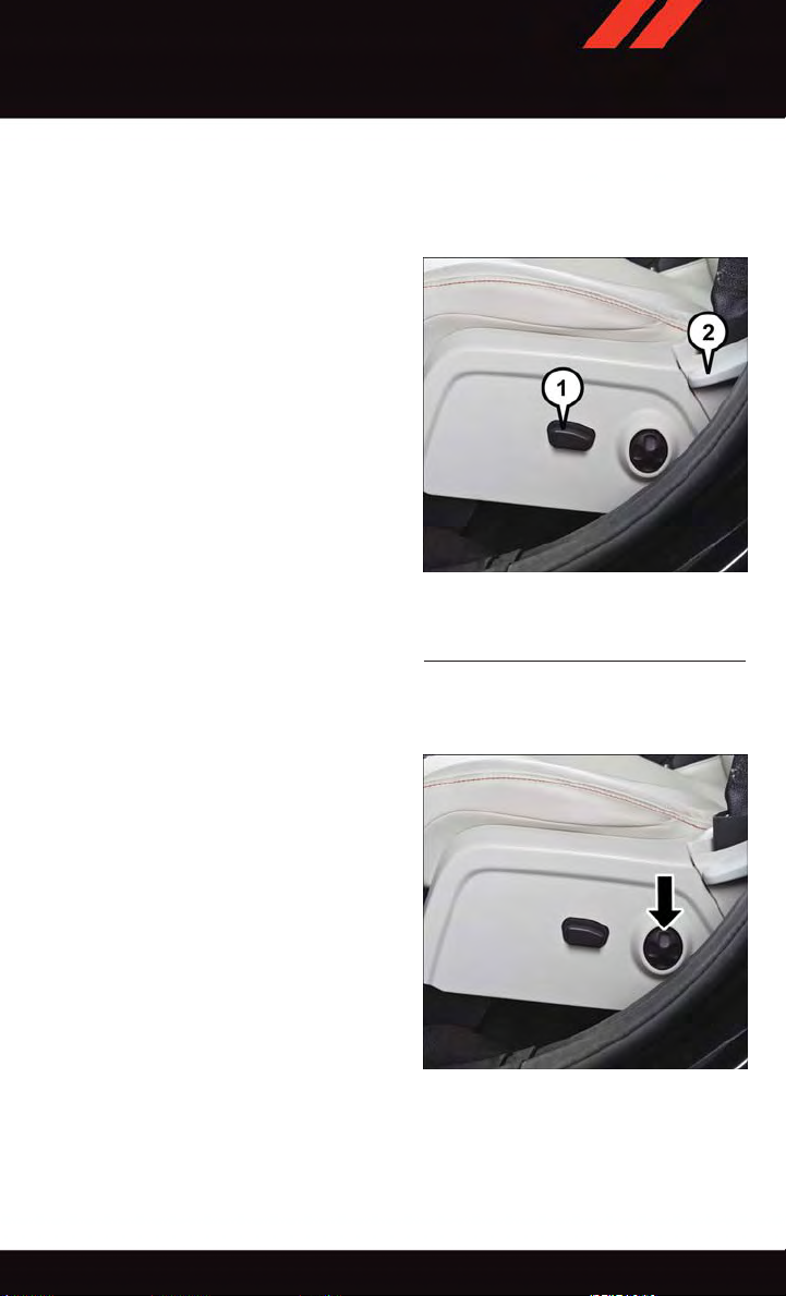
Manual Seat Adjustment
Forward/Rearward
•Liftupontheadjustingbarlocatedat
the front of the seat near the floor and
release it when the seat is at the desired
position. Then, using body pressure,
move forward and backward on the seat
to be sure that the seat adjusters have
latched.
Recliner
•Liftthereclinerleverlocatedontheoutboard side of the seat, lean back and
release at the desired position.
1—ReclinerLever
2—AdjustingBar
Adjusting Bar/Recliner Lever Location
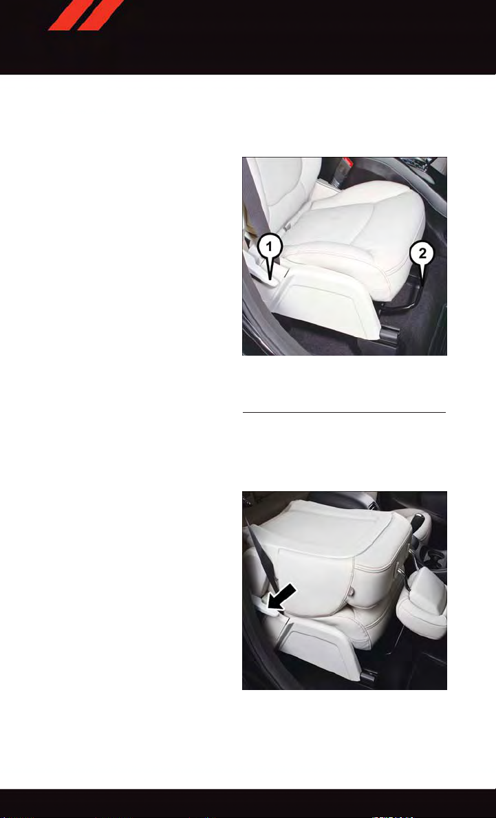
Fold-Flat Front Passenger Seat
•Thefrontpassengerseatcanbefolded
flat to allow for extended cargo space.
Pull up on the recliner lever to fold down
the seatback.
28
Passenger Seat Folded Position
Page 31

GETTING STARTED
Flip 'n Stow™ Front Passenger Seat Storage
•Theseatlatchrelease-loopislocatedin
the center of the seat cushion between
the seat cushion and the seatback. Pull
the loop upward to release the latch and
then forward to open the seat to the
detent position.
NOTE:
Make sure that objects inside the bin do not
interfere with the latch before closing the
seat. Push the seat cushion downward after
closing it to make sure it latches to the
base.
Passenger Seat Storage
CAUTION!
Do not place any article under a power seat or impede its ability to move as it may cause
damage to the seat controls. Seat travel may become limited if movement is stopped
by an obstruction in the seat’s path.
WARNING!
•Adjustingaseatwhilethevehicleismovingisdangerous.Thesuddenmovementof
the seat could cause you to lose control. The seat belt might not be properly
adjusted, and you could be severely injured or killed. Only adjust a seat while the
vehicle is parked.
•Donotridewiththeseatbackreclinedsothattheseatbeltisnolongerresting
against your chest. In a collision, you could slide under the seat belt and be severely
injured or killed. Use the recliner only when the vehicle is parked.
•Becertainthattheseatcushionislockedsecurelyintopositionbeforeusingthe
seat. Otherwise, the seat will not provide the proper stability for passengers. An
improperly latched seat cushion could cause serious injury.
29
Page 32

GETTING STARTED
REAR SEATS
60/40 SPLIT SECOND-ROW PASSENGER SEATS
To Lower The Seatback
•Locatetheseatbackreleaseleveronthe
lower outboard side of the seat.
•Placeonehandon theseatbackand
apply a gentle pressure.
•Lifttheseatbackreleaseleverwiththe
other hand, allowing the seatback to
move forward slightly, and then release
the lever.
•Gentlyguidetheseatbackintothefolded
position.
To Raise The Seatback
•Raisetheseatbackandlockitinplace.
Forward And Rearward Adjustment
•Thecontrolleverisontheoutboardside
of the seat. Lift the lever to move the seat
forward or rearward. Release the lever
once the seat is in the position desired.
Recliner Adjustment
•Theseatbackreleaseleverisontheoutboardsideoftheseat.Toreclinetheseat,lean
back, lift the lever , position the seatback as desired, and then release the lever. To
return the seatback to its normal upright position, lean back, lift the lever , lean forward,
and then release the lever once the seatback is in the upright position.
1—Forward/RearwardAdjustmentLever
2—Recliner/SeatbackReleaseLever
3—Tip’nSlide™ControlLever
Rear Seat Lever Locations
30
Page 33

GETTING STARTED
STADIUM Tip ’n Slide™ (EASY ENTRY/EXIT SEAT) — SEVEN PASSENGER MODELS
To Move The Second-Row Passenger Seat Forward
NOTE:
Raise the 20% seatback/armrest before moving the 60% seat to allow for full seat travel.
•Toallowpassengerstoeasilyenterorexitthethird-rowpassengerseatsmovetheTip’n
Slide™ control lever on the upper outboard side of the seatback forward, and in one
fluid motion, the seat cushion flips upward and the seat moves forward on its tracks.
To Unfold And Move The Second-Row Passenger Seat Rearward
•Movetheseatbackrearwarduntilitlocks
in place and then continue sliding the
seat rearward on its tracks until it locks in
place.
•Pushtheseatcushiondownwardtolock
it in place.
•Adjusttheseattrackpositionasdesired.
Seat In Tip ‘n Slide™ Position
50/50 SPLIT THIRD-ROW PASSENGER SEATS WITH FOLD-FLAT FEATURE
To Fold The Seat
•Withthesecond-rowpassengerseatfullyupright,pullthelatchrelease-looplocatedat
the top of the seatback upward, push the seat forward slightly , and release the
release-loop. Then, continue to push the seat forward. The head restraints will fold
automatically as the seat moves forward.
To Unfold The Seat
•Grasptheassiststraploopontheseatbackandpullittowardyoutoraisetheseatback.
Continue to raise the seatback until it locks in place. Then, raise the head restraint to
lock it in place.
•Tolocktheseatbackinareclinedposition,pullthelatchrelease-looplocatedatthetop
of the seatback upward, allow the seatback to recline, then release the release-loop.
31
Page 34

GETTING STARTED
WARNING!
•Becertainthattheseatbackislockedsecurelyintoposition.Otherwise,theseatwill
not provide the proper stability for child seats and/or passengers. An improperly
latched seat could cause you and others to be severely injured or killed.
•Donotallowapassengertositinathirdrowseatwithouthavingtheheadrestraint
unfolded and locked in place or seatback(s) folded flat. Failure to follow this
warning may result in the passengers being severely injured or killed in the event of
acollision.
•DonotdrivethevehiclewiththeseatintheTip'nSlide™position,asitisonly
intended for entering and exiting the third row seats. Failure to follow this warning
may result in you and others being severely injured or killed.
•Becertainthattheseatbackandseatarelockedsecurelyintoposition.Otherwise,
the seat will not provide the proper stability for child seats and/or passengers. An
improperly latched seat could cause you or others to be severely injured or killed.
HEATED SEATS
Front Heated Seats
The front heated seats control buttons are located within the climate or controls screen of
the touchscreen.
•Presstheheatedseatbutton
•Presstheheatedseatbutton
•Presstheheatedseatbutton
If the HI-level setting is selected, the system will automatically switch to LO-level after
approximately 60 minutes. The LO-level setting will turn Off automatically after approximately 45 minutes.
NOTE:
On models that are equipped with Remote Start, this feature can be programmed to
come on during a Remote Start through the Uconnect
Settings” in “Understanding Your Instrument Panel” in the Owner's Manual on the
DVD.
once to turn the HI setting On.
asecondtimetoturntheLOsettingOn.
athirdtimetoturntheheatingelementsOFF.
®
system. Refer to “Uconnect
®
32
Page 35

GETTING STARTED
WARNING!
•Personswhoareunabletofeelpaintotheskinbecauseofadvancedage,chronic
illness, diabetes, spinal cord injury, medication, alcohol use, exhaustion or other
physical conditions must exercise care when using the seat heater. It may cause
burns even at low temperatures, especially if used for long periods of time.
•Donotplaceanythingontheseatthatinsulatesagainstheat,suchasablanketor
cushion. This may cause the seat heater to overheat. Sitting in a seat that has been
overheated could cause serious burns due to the increased surface temperature of
the seat.
HEATED STEERING WHEEL
The steering wheel contains a heating element that heats the steering wheel to one
temperature setting.
The heated steering wheel control button is located within the Uconnect
gain access to the control buttons through the climate screen or the controls screen.
•Presstheheatedsteeringwheelbutton
•Presstheheatedsteeringwheelbutton
OFF.
Once the heated steering wheel has been turned on, it will operate for up to 80 minutes
before automatically shutting off. The heated steering wheel can shut off early or may not
turn on when the steering wheel is already warm.
NOTE:
On models that are equipped with Remote Start, this feature can be programmed to come
on during a Remote Start through the Uconnect
in “Understanding Your Instrument Panel” in the Owner's Manual on the DVD.
once to turn the heating element ON.
asecondtimetoturntheheatingelement
®
system. Refer to “Uconnect®Settings”
®
system. You can
WARNING!
•Personswhoareunabletofeelpaintotheskinbecauseofadvancedage,chronic
illness, diabetes, spinal cord injury, medication, alcohol use, exhaustion, or other
physical conditions must exercise care when using the steering wheel heater. It may
cause burns even at low temperatures, especially if used for long periods.
•Donotplaceanythingonthesteeringwheelthatinsulatesagainstheat,suchasa
blanket or steering wheel covers of any type and material. This may cause the
steering wheel heater to overheat.
33
Page 36

GETTING STARTED
TILT/TELESCOPING STEERING COLUMN
•Thetilt/telescopingcontrolhandleislocated below the steering wheel at the end
of the steering column.
•Pushdownonthehandletounlockthe
steering column.
•Totiltthesteeringcolumn,movethe
steering wheel upward or downward as
desired.
•Tolengthenorshortenthesteeringcolumn, pull the steering wheel outward or
push it inward as desired.
•Pullupwardonthehandletolockthe
column firmly in place.
Tilt/Telescoping Control Handle
WARNING!
Do not adjust the steering wheel while driving. The tilt/telescoping adjustment must be
locked while driving. Adjusting the steering wheel while driving or driving without the
tilt/telescoping adjustment locked could cause the driver to lose control of the vehicle.
Failure to follow this warning may result in you and others being severely injured or
killed.
34
Page 37

OPERATING YOUR VEHICLE
ENGINE BREAK-IN RECOMMENDATIONS
Alongbreak-inperiodisnotrequiredfortheengineanddrivetrain(transmissionandaxle)
in your vehicle.
Drive moderately during the first 300 miles (500 km). After the initial 60 miles (100 km),
speeds up to 50 or 55 mph (80 or 90 km/h) are desirable.
While cruising, brief full-throttle acceleration within the limits of local traffic laws
contributes to a good break-in. Wide-open throttle acceleration in low gear can be
detrimental and should be avoided.
The engine oil installed in the engine at the factory is a high-quality energy conserving type
lubricant. Oil changes should be consistent with anticipated climate conditions under
which vehicle operations will occur. For the recommended viscosity and quality grades,
refer to “Maintaining Your Vehicle.”
NOTE:
Anewenginemayconsumesomeoilduringitsfirstfewthousandmiles(kilometers)of
operation. This should be considered a normal part of the break-in and not interpreted
as an indication of an engine problem or malfunction.
CAUTION!
Never use Non-Detergent Oil or Straight Mineral Oil in the engine or damage may
result.
35
Page 38

OPERATING YOUR VEHICLE
TURN SIGNAL/WIPER/WASHER/HIGH BEAM LEVER
Multifunction Lever
Turn Signal/Lane Change Assist
Tap t h e lev er up o r d own o n ce a nd the t u rn s ign a l (ri g ht o r l eft ) w ill f l ash t h ree t i mes a n d
automatically turn off.
Front Wipers
Intermittent, Low And High Operation
•Rotatetheendofthelevertothefirstdetentpositionforoneoffiveintermittent
settings, the second detent for low wiper operation and the third detent for high wiper
operation.
Washer Operation
•Pushtheendoftheleverintotheseconddetentandrelease.
Mist
•Pushtheendoftheleverintothefirstdetentandrelease.
NOTE:
The mist feature does not activate the washer pump; therefore, no washer fluid will be
sprayed on the windshield. The wash function must be activated in order to spray the
windshield with washer fluid.
Rear Wiper
Wiper Operation
•Rotatethecenterportionoftheleverforwardtothefirstdetentforrearwiperoperation.
Washer Operation
•Rotatethecenterportionoftheleverpastthefirstdetenttoactivatetherearwasher.
36
Page 39

OPERATING YOUR VEHICLE
HEADLIGHT SWITCH
Automatic Headlights/Parking Lights/Headlights
•Rotatetheheadlightswitch,locatedon
the instrument panel to the left of the
steering wheel, to the first detent
for parking lights and to the second detent for headlights
•Withtheparkinglightsorlowbeam
headlights on, push the headlight switch
once for fog lights.
•RotatetheheadlightswitchtoAUTOfor
Automatic headlights.
•WhensettoAUTO,thesystemautomatically turns the headlights on or off based
on ambient light levels.
Instrument Panel Dimmer
•Rotatethedimmercontroltotheextreme bottom position to fully dim the
instrument panel lights and prevent the
interior lights from illuminating when a door is opened.
•Rotatethedimmercontroluptoincreasethebrightnessoftheinstrumentpanelwhen
the parking lights or headlights are on.
•Rotatethedimmercontroluptothenextdetentpositiontofullybrightentheodometer
and radio when the parking lights or headlights are on.
•Rotatethedimmercontroluptothelastdetentpositiontoturnontheinteriorlighting.
•Ifyourvehicleisequippedwithatouchscreen,thedimmingisprogrammablethrough
the Uconnect
ment Panel” in the Owner's Manual on the DVD for further details.
®
.
Headlight Switch
1—Auto
2—RotateHeadlightSwitch
3—PushFogLight
4—RotateDimmer
system. Refer to “Uconnect®Settings” in “Understanding Your Instru-
Door/Map Pocket Lights
•RotatetheDoor/MapPocketcontrolupordowntoincreaseordecreasethebrightness
of the door handle and map pocket lighting when the parking lights or headlights are on.
37
Page 40

OPERATING YOUR VEHICLE
ELECTRONIC SPEED CONTROL
The Electronic Speed Control switches are located on the steering wheel.
Cruise ON/OFF
•PushtheON/OFFbuttontoactivatethe
Speed Control.
NOTE:
CRUISE
cluster to indicate the Speed Control is on.
•PushtheON/OFFbuttonasecondtime
to turn the system off.
SET
With the Speed Control on, push and release the SET – button to set a desired
speed.
Accel/Decel
To Increase Speed
When the Electronic Speed Control is set,
you can increase speed by pushing the RES
+ button.
The drivers preferred units can be selected through the instrument panel settings if
equipped. The speed increment shown is dependant on the chosen speed unit of U.S.
(MPH) or Metric (km/h):
U.S. Speed (MPH)
•PushingtheRES+ button once will result in a 1 MPH increase in set speed. Each
subsequent tap of the button results in an increase of 1 MPH.
•Ifthebuttoniscontinuallypushed,thesetspeedwillcontinuetoincreaseuntilthe
button is released, then the new set speed will be established.
Metric Speed (km/h)
•PushingtheRES+ button once will result in a 1 km/h increase in set speed. Each
subsequent tap of the button results in an increase of 1 km/h.
•Ifthebuttoniscontinuallypushed,thesetspeedwillcontinuetoincreaseuntilthe
button is released, then the new set speed will be established.
will appear on the instrument
Electronic Speed Control Switches
1—PushOn/Off
2—PushResume/Accel
3—PushSet/Decel
4—PushCancel
38
Page 41

OPERATING YOUR VEHICLE
To Decrease Speed
When the Electronic Speed Control is set, you can decrease speed by pushing the SET button.
The drivers preferred units can be selected through the instrument panel settings if
equipped. The speed decrement shown is dependant on the chosen speed unit of U.S.
(MPH) or Metric (km/h):
U.S. Speed (MPH)
•PushingtheSET- button once will result in a 1 MPH decrease in set speed. Each
subsequent tap of the button results in a decrease of 1 MPH.
•Ifthebuttoniscontinuallypushed,thesetspeedwillcontinuetodecreaseuntilthe
button is released, then the new set speed will be established.
Metric Speed (km/h)
•PushingtheSET- button once will result in a 1 km/h decrease in set speed. Each
subsequent tap of the button results in a decrease of 1 km/h.
•Ifthebuttoniscontinuallypushed,thesetspeedwillcontinuetodecreaseuntilthe
button is released, then the new set speed will be established.
Resume
To r esu m e a prev iou s ly sel e cte d s e t s pee d in m emo ry, p ush t he RES + but t on and r ele ase .
Cancel
Push the CANCEL button, or apply the brakes to cancel the set speed and maintain the set
speed memory.
Push the ON/OFF button to turn the system off and erase the set speed memory.
WARNING!
•LeavingtheElectronicSpeedControlsystemonwhennotinuseisdangerous.You
could accidentally set the system or cause it to go faster than you want. You could
lose control and have a collision. Always leave the Electronic Speed Control system
off when you are not using it.
•ElectronicSpeedControlcanbedangerouswherethesystemcannotmaintaina
constant speed. Your vehicle could go too fast for the conditions, and you could lose
control. A collision could be the result. Do not use Electronic Speed Control in
heavy traffic or on roads that are winding, icy, snow-covered or slippery.
39
Page 42

OPERATING YOUR VEHICLE
CLIMATE CONTROL
Uconnect® 4.3 Manual Climate Controls
Uconnect® 4.3 Manual Climate Controls
1—TemperatureControlButton
2—MAXA/CButton
3—A/CButton
4—AirRecirculationButton
5—FrontDefrostButton
6—RearDefrostButton
7—ModeControlButton
8—ClimateOffButton
9—ClimateControlButton
40
Page 43

OPERATING YOUR VEHICLE
Uconnect® 8.4 Automatic Climate Controls
Uconnect® 8.4 Automatic Climate Controls
1—A/CButton
2—AirRecirculationButton
3—AUTOButton
4—FrontDefrostButton
5—RearDefrostButton
6—REARCLIMATEButton
7—PassengerTemperatureControl
8—SYNCButton
9—IncreaseBlowerSpeedButton
10 — Mode Control Buttons
11 — Decrease Blower Speed Button
12 — OFF Button
13 — Driver T emperature Control
14 — MAX A/C Button
41
Page 44

OPERATING YOUR VEHICLE
Climate Control Knobs
Climate Control Knobs
1—A/CButton
2—AirRecirculationButton
3—FrontDefrostButton
4—RearDefrostButton
5—PassengerTemperatureControl
6—RotateBlowerControlKnob
7—AUTOButton
8—DriverTemperatureControl
9—OFFButton
•Foryourconveniencetheclimatecontrolscanbeoperatedbyusingthebuttonsonthe
touchscreen located or the climate control knobs below the Uconnect
®
display.
Automatic Operation — If Equipped
•PushtheAUTObuttonorpressthe“AUTO”buttononthetouchscreen.
•SelectthedesiredtemperaturebypressingtheTemperatureControlsforthedriveror
passenger.
•Thesystemwillmaintainthesettemperatureautomatically.
42
Page 45

OPERATING YOUR VEHICLE
SYNC Temperature Button — If Equipped
Press the SYNC button on the touchscreen once to control driver and passenger
temperatures simultaneously.
Press the SYNC button on the touchscreen a second time to control the temperatures
individually.
Air Recirculation
•UserecirculationformaximumA/Coperation.
•Forwindowdefogging,turntherecirculationbuttonoff.
•IftheRecirculationbuttononthefaceplateispushedwhileintheAUTOmode,the
indicator light may flash three times to indicate the cabin air is being controlled
automatically. The “Recirculation” button on the touchscreen will be greyed out in
these conditions.
Heated Mirrors
The mirrors are heated to melt frost or ice. This feature is activated whenever you turn on
the rear window defroster.
PARKVIEW® REAR BACK-UP CAMERA
You can s ee an on-s creen im age of the r ear of yo ur ve hicle wh enever t he shif t lever i s put
into REVERSE. The ParkView
display screen, located on the center stack of the instrument panel.
If the radio display screen appears foggy, clean the camera lens located on the liftgate.
Refer to your Owner's Manual on the DVD for further details.
®
Rear Back-Up Camera image will be displayed on the radio
WARNING!
Drivers must be careful when backing up; even when using the ParkView®Rear
Back-Up Camera. Always check carefully behind your vehicle, and be sure to check for
pedestrians, animals, other vehicles, obstructions, or blind spots before backing up.
You must con tinue to pa y attent ion while b acking u p. Failure to do so can re sult in
serious injury or death.
43
Page 46

OPERATING YOUR VEHICLE
POWER SUNROOF
•Thepowersunroofswitchislocatedon
the overhead console.
Opening Sunroof
Express Open
Push the switch rearward and release it
within one-half second. The sunroof will
fully open and stop automatically.
Manual Open
Push and hold the switch rearward to open
the sunroof. Any release of the switch will
stop the movement, and the sunroof will
remain in a partially open position until the
switch is pushed again.
Venting Sunroof
Push and release the button and the sunroof will open to the vent position.
This is called “Express Vent” and will occur
regardless of sunroof position. During Express Vent operation, any movement of the switch
will stop the sunroof.
1—OpeningSunroof
2—VentingSunroof
3—ClosingSunroof
Sunroof Switch
Closing Sunroof
Express Closing
Push the switch forward and release it within one-half second. The sunroof will fully close
automatically from any position.
Manual Closing
Push and hold the switch forward to close the sunroof. Any release of the switch will stop
the movement, and the sunroof will remain in a partially closed position until the switch
is pushed again.
Pinch Protection Feature
This feature will detect an obstruction in the opening of the sunroof during Express Close
operation. If an obstruction in the path of the sunroof is detected, the sunroof will
automatically retract. Remove the obstruction if this occurs. Next, push the switch
forward and release to Express Close.
44
Page 47

OPERATING YOUR VEHICLE
NOTE:
If three consecutive sunroof close attempts result in Pinch Protect reversals, the fourth
close attempt will be a Manual Close movement with Pinch Protect disabled.
WARNING!
•Donotletchildrenplaywiththesunroof.Neverleavechildrenunattendedina
vehicle, or with access to an unlocked vehicle. Do not leave the Key Fob in or near
the vehicle, and do not leave the ignition of a vehicle equipped with Keyless
Enter-N-Go™ in the ACC or ON/RUN mode. Occupants, particularly unattended
children, can become entrapped by the power sunroof while operating the power
sunroof switch. Such entrapment may result in serious injury or death.
•Inacollision,thereisagreaterriskofbeingthrownfromavehiclewithanopen
sunroof. You could also be severely injured or killed. Always fasten your seat belt
properly and make sure all passengers are properly secured.
•Donotallowsmallchildrentooperatethesunroof.Neverallowyourfingers,other
body parts, or any object to project through the sunroof opening. Injury may result.
WIND BUFFETING
Wind buffeting can be described as a helicopter-type percussion sound. If buffeting
occurs with the rear windows open, adjust the front and rear windows together.
If buffeting occurs with the sunroof open, adjust the sunroof opening, or adjust any
window. This will minimize buffeting.
45
Page 48

ELECTRONICS
YOUR VEHICLE'S SOUND SYSTEM
1. Uconnect®Voice Command Button pg. 72
®
2. Uconnect
3. Steering Wheel Audio control (Left) pg. 76
4. Steering Wheel Audio control (Right) pg. 76
5. Volume Knob/Audio Mute Button
6. Uconnect
46
Phone Button pg. 66
®
Radio pg. 48
Page 49

ELECTRONICS
7. Tune/Scroll Knob/Browse/Enter Button
8. SD Card Slot (push in to insert/eject) pg. 66
9. Front Power Outlet pg. 82
10. CD Slot
11. CD Eject Button
12. Audio Jack/USB Port pg. 65
47
Page 50

ELECTRONICS
IDENTIFYING YOUR RADIO
Uconnect® 4.3 & 4.3S
•Models4.3and4.3Shavea4.3inch
touchscreen with buttons on the faceplate on each side of it.
•Model4.3ShasallModel4.3features,
plus SiriusXM Satellite Radio (1 year trial
subscription included).
•Model4.3Sisidentifiedbythepresence
of SAT on the band button, indicating the
presence of satellite radio.
Uconnect® 8.4 & 8.4N
•Models8.4and8.4Nhavean8.4inch
touchscreen.
•Model8.4NhasallModel8.4features,
plus Garmin
Trav el Li n k (1 - yea r tri al su bscr ipt i on i n cluded).
•Model8.4Nisidentifiedbytheunique
Nav button on the main screen menu bar,
located at the bottom of the screen, and
the presence of SiriusXM T ravel Link
within the More menu.
®
Navigation and SiriusXM
Uconnect® 4.3 & 4.3S
Uconnect® 8.4 & 8.4N
48
Page 51

ELECTRONICS
Uconnect® 4.3 & 4.3S AT A GLANCE
Uconnect® 4.3 & 4.3S
1—Radio:AM/FM/SIRIUSSatelliteRadio(IfEquipped)
2—StatusBar
3—Settings:Clock,Display,etc.
4—ScreenOFF/ON
5—MORE:Uconnect
6—Player:CD,iPod
®
Phone, Compass, etc.
®
,USBDeviceorAUXDevice
Displaying The Time
•IfthetimeisnotcurrentlydisplayedatthetopofthescreenwheninRadiomode,push
the SETTINGS button, then press “Clock.” Select “Show T ime,” then press “On.”
Setting The Time
•PushtheSETTINGSbuttononthefaceplate,thenpressthe“Clock”buttononthe
touchscreen.
•Pressthe“Time”buttononthetouchscreen.
•Pressthe“UporDown”buttonsonthetouchscreentoadjustthehours,minutesor
AM/PM.
NOTE:
12hr format and 24hr format can also be set.
•Oncethetimeissetpressthe“Done”buttononthetouchscreentoexitthetime
screen.
49
Page 52

ELECTRONICS
Audio Settings
•PushtheSETTINGSbuttononthefaceplateontherightsideoftheunit.
•Thenscrolldownandpressthe“Audio”buttononthetouchscreentogettotheAudio
menu.
•TheAudioMenushowsthefollowingoptionsforyoutocustomizeyouraudiosettings.
•Equalizer
•Balance/Fade
•SpeedAdjustVolume
•Pressthe“Exit”buttononthetouchscreentoexitfromtheAudioMenu.
Equalizer
•Pressthe“Equalizer”buttononthetouchscreentoadjusttheBass,MidandTreble.
Use the “+” or “–” button on the touchscreen to adjust the equalizer to your desired
settings. Press the “Done” button on the touchscreen when done.
Balance/Fade
•Pressthe“Balance/Fade”buttononthetouchscreentoadjustthesoundfromthe
speakers. Use the “arrow” button on the touchscreen to adjust the sound level from the
front and rear or right and left side speakers. Press the center “C” button on the
touchscreen to reset the balance and fade to the factory setting. Press the “Done”
button on the touchscreen when done.
Speed Adjust Volume
•Pressthe“SpeedAdjustVolume”buttononthetouchscreentoselectbetweenOFF,1,
2or3.Thiswilldecreasetheradiovolumerelativetoadecreaseinvehiclespeed.Press
the “Done” button on the touchscreen when done.
50
Page 53

Uconnect® 8.4 & 8.4N AT A GLANCE
Uconnect® 8.4N
1—StatusBar
2—SmallNavigationMap(8.4N)
3—MoreSettingsButton
4—Uconnect
5—GarminNavigationButton(8.4N)
®
Phone Button
ELECTRONICS
6—ClimateControlButton
7—ControlsButton
8—PlayerButton
9—RadioButton
51
Page 54

ELECTRONICS
Displaying The Time
•Ifthetimeisnotcurrentlydisplayedontheradioorplayermainpage,pressthe“More”
button on the touchscreen and then press the “Settings” button on the touchscreen. In
the Settings list, press the “Clock” button on the touchscreen, then press the check box
next to Show T ime in Status Bar.
Setting The Time
•Model8.4NsynchronizestimeautomaticallyviaGPS,soshouldnotrequireanytime
adjustment. If you do need to set the time manually, follow the instructions below for
Model 8.4.
•ForModel8.4,turntheuniton,thenpressthe“TimeDisplay”atthetopofthescreen.
Press “Yes”.
•Ifthetimeisnotdisplayedatthetopofthescreen,press“More”buttononthe
touchscreen and then “Settings” button on the touchscreen. In the Settings screen,
press the “Clock” button on the touchscreen, then check or uncheck this option.
•Press“+”or“–”nexttoSetTimeHoursandSetTimeMinutestoadjustthetime.
•Ifthesefeaturesarenotavailable,uncheckthe“Sync”withGPSbox.
•Press“X”tosaveyoursettingsandexitoutoftheClockSettingscreen.
Audio Settings
•Pressthe“Audio”buttononthetouchscreentoactivatetheAudiosettingsscreento
adjust Balance\Fade, Equalizer and Speed Adjusted Volume.
•YoucanreturntotheRadioscreenbypressingthe“X”locatedatthetopright.
Balance/Fade
•Pressthe“Balance/Fade”buttononthetouchscreentoBalanceaudiobetweenthe
front speakers or fade the audio between the rear and front speakers.
•Pressingthe“Front,”“Rear,””Left”or“Right”buttonsonthetouchscreenorpress
and drag the red Speaker Icon to adjust the Balance/Fade.
Equalizer
•Pressthe“Equalizer”buttononthetouchscreentoactivatetheEqualizerscreen.
•Pressthe“+”or“–”buttonsonthetouchscreen,orbypressinganddraggingoverthe
level bar for each of the equalizer bands. The level value, which spans between ±9, is
displayed at the bottom of each of the Bands.
Speed Adjusted Volume
•Pressthe“SpeedAdjustedVolume”buttononthetouchscreentoactivatetheSpeed
Adjusted Volume screen. The Speed Adjusted Volume is adjusted by pressing the “+”
and “–” buttons or by pressing and dragging over the level bar. This alters the automatic
adjustment of the audio volume with variation to vehicle speed.
52
Page 55

RADIO
1—RadioStationPresets
2—ViewAllPresets
3—SeekUp
4—Channel/StationInformation
ELECTRONICS
Models 4.3 & 4.3S
5—AudioSettings
6—DirectTuneRadioStation
7—RadioBand
8—SeekDown
53
Page 56

ELECTRONICS
1—RadioStationPresets
2—TogglePresets1–6and7–12
3—RadioBandButtons
4—BrowseAndManageStations
Uconnect 8.4 Radio
5—SeekDownButton
6—DirectTuneToARadioStation
7—SeekUpButton
8—AudioSettingsButton
•ToaccesstheRadiomode,pushtheRADIObuttonontheupperleftsideofthe
faceplate (4.3 & 4.3S) or the “Radio” button on the touchscreen at the lower left of the
screen (8.4 & 8.4N).
•Unlessotherwisenoted,theinformationprovidedontheoperationandfunctionalityof
the radios in this section is common to all Uconnect
Selecting Radio Stations
•Pressthe“Radioband”buttononthetouchscreentocyclethroughAM,FMorSAT
(4.3 & 4.3S) or the desired radio band (AM, FM or SA T) button on the touchscreen (8.4
&8.4N).SiriusXMSatelliteRadioisnotavailableonthe4.3.
Seek Up/Seek Down
•Pressthe“Seekarrow”buttonsonthetouchscreenforlessthantwosecondstoseek
through radio stations.
•Pressandholdeither“Seekarrow”buttononthetouchscreenformorethantwo
seconds to bypass stations without stopping. The radio will stop at the next listenable
station once the arrow button on the touchscreen is released.
®
radios.
54
Page 57

ELECTRONICS
Direct Tune
•Tunedirectlytoaradiostationbypressingthe“Tune”buttononthescreen,and
entering the desired station number.
Store Radio Presets
•Yourradiocanstore12totalpresetstations.Theyareshownatthetopofyourscreen.
To see a ll 1 2 s tat ion s , Pre ss t h e “Al l” b u tto n on t h e t o uch s cre en ( 4 .3 & 4 .3S ) or p r ess
the “arrow” button on the touchscreen at the top right of the screen to toggle between
the six presets (8.4 & 8.4N).
•Tosetastationintomemorypressandholdthedesirednumberedbuttononthe
touchscreen for more than two seconds or until you hear a confirmation beep.
SiriusXM SATELLITE RADIO
•SiriusXMSatelliteRadiogivesyouover130channels,including100%commercialfree music from nearly every genre, plus all your favorite sports, news, talk and
entertainment channels – all with crystal clear , coast-to-coast coverage, all in one place
and all at your fingertips.
•ToaccessSiriusXMSatelliteRadio,pressthe“Radioband”buttononthetouchscreen
and select the “SAT” button on the touchscreen (4.3S) or press the “SAT” button on
the touchscreen on the main Radio screen (8.4 & 8.4N).
•ThefollowingdescribesfeaturesthatareavailablewheninSiriusXMSatelliteRadio
mode.
•Unlessotherwisenoted,theinformationprovidedontheoperationandfunctionalityof
the radios in this section is common to all Uconnect
®
radios.
Selecting SiriusXM Satellite Channels
Seek Up/Seek Down
•Pressthe“Seekarrow”buttonsonthetouchscreenforlessthantwosecondstoseek
through channels in SA T mode.
•Pressandholdeither“arrow”buttononthetouchscreenformorethantwosecondsto
bypass channels without stopping. The radio will stop at the next listenable channel
once the arrow button on the touchscreen is released.
Direct Tune
•TunedirectlytoaSATchannelbypressingthe“Tune”buttononthescreen,and
entering the desired station number.
Info (4.3S Only)
•ProvidesdetailedinformationaboutthecurrentSiriusXMSatelliteRadiochannel.
More... (4.3S Only)
•Accessmoremenus:Audio,Favorites,GameZone,andReplay.
55
Page 58

ELECTRONICS
Traffic & Weather (U.S. Residents/8.4 & 8.4N Only)
•AutomaticallytellsyouwhenTraffic&Weatherforafavoritecityisavailable,andgives
you the option to switch to that channel. Select Traffic & Weather then press “Jump” to
activate the feature. After listening to Traffic and Weather, press “Jump” again to return
to the previous channel.
Fav (8.4 & 8.4N Only)
•Activatesthefavoritesmenu.Youcanaddupto50favoriteartistsorsongs.Justpress
“Add Fav Artist” or “Add Fav Song” while the song is playing. You will then be alerted
any time one of these songs, or works by these artists, is playing on other SiriusXM
Satellite Radio channels.
SiriusXM Parental Controls
•Youcanskiporhidecertainchannelsfromviewifyoudonotwantaccesstothem.Push
the SETTINGS button on the faceplate (4.3S) or press the “More” button on the
touchscreen, then the “Settings” button on the touchscreen (8.4 & 8.4N), next press
the “SiriusXM Satellite Radio Setup” button on the touchscreen, then select “Channel
Skip.” Press the channel(s) to be skipped (4.3S) or press the box, check-mark, next to
the channel you want skipped (8.4 & 8.4N). They will not show up in normal usage.
•SiriusXMSatelliteRadioalsoofferstheoptiontopermanentlyblockselectedchannels.
Call 1-888-539-7474 and request the Family Package.
Browse
•LetsyoubrowsetheSiriusXMSatelliteRadiochannellisting,Favorites,Genres,Game
Zone, and Weather channels. Jump setting, and also provides the SiriusXM Satellite
Radio channel list. Browse contains many sub-menus.
56
Page 59

ELECTRONICS
Browse
Sub-Menu
All Shows the channel listing.
Genre Provides a list of all genres, and lets you jump to a channel within the selected
Presets (8.4
&8.4NOnly)
Favorites Lets you manage artists and songs in the Favorites list and configure Alert
Game Zone Provides alerts when your favorite sports teams are starting a game which is
Traf fic /
Weather
(4.3S only)
Jump (8.4 &
8.4N only)
Sub-Menu Description
genre.
Lets you scroll the list of Preset satellite channels. Press the “Channel”, or
press “Enter” on the Tune knob, to go to that channel. Press the “Trash can”
icon to delete a preset. Your presets are also shown at the top of the main
Satellite Radio screen.
Settings to let you know when favorite songs or artists are playing on other
channels). Also, view a list of channels airing any of your Favorites.
being aired on other SiriusXM Satellite Radio channels, or when their game
score is announced. You can select and manage your Teams list here, and
configure alerts.
Lets you browse Traffic & Weather information by city.
Lets you select your favorite cities for Traffic & Weather information, by
selecting Traffic, then Jump feature on the main satellite radio screen.
Replay
•Letsyoureplayupto44minutesofthecontentofthecurrentSiriusXMSatelliteRadio
channel.
Replay
Option
Play/Pause Press to Pause content playback. Press “Pause/Play” again to resume
Rewind/RW Rewinds the channel content in steps of five seconds. Press and hold to
Fast
Forward/FW
Replay Time Displays the amount of time in the upper center of the screen by which your
Live Resumes playback of Live content at any time while replaying rewound
Option Description
playback.
rewind continuously, then release to begin playing content at that point.
Forwards the content, and works similarly to Rewind/RW. However, Fast
Forward/FW can only be used when content has been previously rewound.
content lags the Live channel.
content.
57
Page 60

ELECTRONICS
iPod®/CD/AUX CONTROLS
Models 4.3 & 4.3S
Models 4.3 & 4.3S
1—MusicSource
2—More:AudioSettingsandShuffle
3—CurrentTrackInformation
4—Play/Pause
5—Source:Disc,iPod
6—BrowseMusicBy:Folder,Artist,Playlist,Song,AlbumOrGenre
®
,AUXOrBluetooth
®
®
•TheiPod
faceplate to enter the Player main screen, then press the “Source” button on the
touchscreen and choose between Disc, AUX, iPod
NOTE:
Uconnect
switch to the appropriate mode when something is first connected or inserted into the
system.
/CD/AUX controls are accessed by pushing the PLAYER button on the
®
or Bluetooth®.
®
will usually automatically
Source 4.3 & 4.3S
58
Page 61

ELECTRONICS
Models 8.4 & 8.4N
Models 8.4 & 8.4N
1—MusicSource:Disc,iPod®,SDCard,AUXOrBluetooth
2—RepeatTrack
3—ShuffleMusicTracks
4—MusicTrackInformation
5—SongsInQueue
6—BrowseMusicBy:Folder,Artist,Playlist,Song,AlbumOrGenre
®
The iPod®/USB, CD, Audio Jack, SD Card or Bluetooth®source is accessed by pressing the
•
“Player” button on the touchscreen to enter the Player main screen, then press the “Source”
button on the touchscreen and choose between Disc, Aux, iPod
NOTE:
Uconnect
switch to the appropriate mode when something is first connected or inserted into the
system.
®
will usually automatically
®
,Bluetooth®or SD Card.
Source 8.4 & 8.4N
59
Page 62

ELECTRONICS
GARMIN® NAVIGATION
Garmin® Navigation (8.4N Only)
Uconnect®8.4N integrates Garmin’s consumer-friendly navigation into your vehicle.
Garmin Navigation includes Lane Assist and Junction View , Speed Limit information, and
adatabasewithoversixmillionpointsofinterest.
•Pressthe“Nav”buttononthetouchscreeninthemenubartoaccesstheNavigation
system.
Changing The Navigation Voice Prompt Volume
1. Program a destination.
2. While traveling on your route, press the upper left area of the map screen where your
next turn is displayed.
3. The Navigation system will then repeat the distance to your next turn.
4. While the Navigation system is speaking, use the ON/OFF VOLUME rotary knob to
adjust the volume to a comfortable level. Please note the volume setting for Navigation
Voice Prompt is different than the audio system.
60
Page 63

Main Navigation Menu
1—WhereTo?Button
2—ViewMapButton
3—SettingsButton
ELECTRONICS
Main Navigation Menu Touchscreen
4—ToolsButton
5—DetourButton
6—StopButton
Acquiring Satellites
•TheGPSSatellitestrengthbarsindicatethestrengthofyoursatellitereception.
•Acquiringsatellitesignalscantakeafewminutes.Whenatleastoneofthebarsis
green, your device has acquired satellite signals. If no signal is found the Navigation
system still can operate with internal gyro direction & location based on data provided
by the vehicle.
•DeadReckoningtechnologyusesthespeedsensorsattachedtoyourvehicle’sdrivetrain, and a gyroscope, to supplement the existing GPS data. The combined data
provides accurate positioning for your vehicle in tunnels, indoor parking garages, urban
canyons, and any other area where GPS signals can become obstructed.
Finding Points Of Interest
•FromthemainNavigationmenupress“WhereTo?”thenpress“PointsofInterest.”
•SelectaCategory,thenasubcategoryifnecessary.
•Selectyourdestinationandpress“Go.”
61
Page 64

ELECTRONICS
Finding A Place By Spelling The Name
•FromtheMainNavigationMenupress“Whereto?”press“PointsofInterest”andthen
press “Spell Name.”
•Enterthenameofyourdestination.
•Press“Done.”
•Selectyourdestinationandpress“Go.”
Entering A Destination Address
•FromthemainNavigationmenu,press“WhereTo?”thenpress“Address.”
•Followtheon-screenpromptstoentertheaddressandpress“Go.”
Searching Near Another Location
•FromthemainNavigationmenu,press“WhereTo?”Pressadestinationandpress
“Near.”
•Selectanoptionfromtheavailablechoices.
Setting Or Changing Your Home Location
•Pressthe“Nav”buttononthetouchscreeninthemenubartoaccesstheNavigation
system and the Main Navigation menu.
•Press“WhereTo?”thenpress“GoHome.”
•Youmayenteryouraddressdirectly,useyourcurrentlocationasyourhomeaddress,or
choose from recently found locations.
•ToedityourHomelocation(orothersavedlocations),press“WhereTo?”fromtheMain
Navigation menu, press “Favorites,” then press the location you want to edit. After
selecting a location to edit, press “Press for More,” then “Edit.”
Go Home
•AHomelocationmustbesavedinthesystem.FromtheMainNavigationmenu,press
“Where To?” then press “Go Home.”
62
Page 65

Following Your Route
1—DistanceToNextTurn
2—CurrentLocation
3—ZoomInButton
4—ZoomOutButton
5—CurrentSpeed
ELECTRONICS
Following Your Route
6—PressAndDragMap
7—YourLocationOnTheMap
8—EstimatedTimeOfArrival
9—ReturnButton
•Yourrouteismarkedwithamagentalineonthemap.Ifyoudepartfromtheoriginal
route, your route is recalculated. A speed limit icon could appear as you travel on major
roadways.
•LaneAssisthelpsyoudecidewhichlanetobeinatupcomingjunctions.
•JunctionViewgivesyouanexpandedviewasjunctionsapproach.
Adding A Via Point
•Toaddastopbetweenyourcurrentlocationandyourenddestination,youmustbe
navigating a route.
•Pressthe“backarrow”multipletimestoreturntotheMainNavigationmenu.
•Press“WhereTo?”thensearchfortheviapoint.Selecttheviapointtoaddfromthe
search results.
•Press“Go,”thenpress“AddasaViaPoint.”
63
Page 66

ELECTRONICS
Taking A Detour
•Totakeadetouryoumustbenavigatingaroute.
•Press“Detour.”
NOTE:
If the route you are currently taking is the only reasonable option, the device might not
calculate a detour.
SiriusXM TRAVEL LINK
SiriusXM Travel Link (8.4N Only)
•SiriusXMTravelLinkisonlyavailableintheUnitedStates.
•SiriusXMTravelLinkbringsawealthofusefulinformationintoyourvehicleandrightto
your fingertips.
•ToaccessTravelLink,pressthe“More”buttononthetouchscreen,thenthe“Travel
Link” button on the touchscreen.
NOTE:
SiriusXM Travel Link requires a subscription, sold separately after the 1 year trial
subscription included with your vehicle purchase.
64
SiriusXM Travel Link — 8.4N
Page 67

ELECTRONICS
1 – Fuel Prices
2 – Movie Listings
3 – Sports Scores
4 – SiriusXM
5 – My Favorites
6 – Weather
View detailed price information for fuel stations near your current
location.
View information on movies that are playing at theaters near your
current location.
View scores and upcoming events for all major sports.
View subscription information.
View and store your favorite location, theater and sport teams for
quick access.
View detailed weather conditions, forecasts and ski/snowboarding
conditions at local resorts.
PLAYING iPod®/USB/MP3 DEVICES
•TherearemanywaystoplaymusicfromiPod®/MP3 players or USB devices through
your vehicles sound system.
Audio Jack (AUX)
•TheAudioJack,locatedinthecenterconsole,allowsaportabledevice,suchasan
MP3 player or an iPod
system, using a 3.5 mm audio cable, to amplify the source and play through the vehicle
speakers.
•Pressingthe“Player”buttononthetouchscreenthenchooseAUXsourcewillchange
the mode to auxiliary device if the Audio Jack is connected, allowing the music from
your portable device to be heard through the vehicles speakers.
•Thefunctionsoftheportabledevicearecontrolledusingthedevicebuttons.The
volume may be controlled using the radio or portable device.
•Toroutetheaudiocableoutofthecenterconsole,usetheaccesscutoutinthefront
of the console.
®
,tobepluggedintotheradioandutilizethevehiclessound
USB Port
•ConnectyouriPod®or compatible device using a USB cable into the USB Port. The
USB Port is contained within the center console. USB Memory sticks with audio files
can also be used. Then, audio from the device can be played on the vehicles sound
system while providing metadata (artist, track title, album, etc.) information on the
radio display.
®
•Whenconnected,theiPod
or Steering Wheel Audio Controls to play, skip to the next or previous track, browse, and
list the contents.
®
•TheiPod
device).
•ToroutetheUSB/iPod
front of the console.
battery charges when plugged into the USB port (if supported by the specific
/compatible USB device can be controlled using the radio
®
cable out of the center console, use the access cut out in the
65
Page 68

ELECTRONICS
NOTE:
®
•WhenconnectingyouriPod
minutes to read your music, depending on the number of files. For example, the system
will take approximately five minutes for every 1,000 songs loaded on the device. Also
during the reading process, the Shuffle and Browse functions will be disabled. This
process is needed to ensure the full use of your iPod
first time it is connected. After the first time, the reading process of your iPod
considerably less time unless changes are made or new songs are added to the playlist.
•TheUSBportsupportscertainMini,Classic,Nano,Touch,andiPhone
USB port also supports playing music from compatible external USB Mass Storage
Class memory devices. Some iPod
port features. Please visit Apple’s website for iPod
SD Card (8.4 and 8.4N Only)
•PlaysongsstoredonanSDcardinsertedintotheSDcardslot,locatedontheradio
faceplate.
•SongplaybackcanbecontrolledusingtheradioorSteeringWheelAudioControlsto
play, skip to the next or previous track, browse, and list the contents.
Bluetooth® Streaming Audio
•IfequippedwithUconnect®Voice Command, your Bluetooth®-equippediPod
devices, cell phones or other media players, may also be able to stream music to your
vehicles sound system. Your connected device must be Bluetooth
paired with your Uconnect
You can ac cess th e music from you r conne cted Bl uetooth
“Source” button on the touchscreen while in Player mode.
device for the first time, the system may take several
®
features and only happens the
®
software versions may not fully support the USB
®
system (see Uconnect®Phone for pairing instructions).
®
software updates.
®
device by pressing the
®
®
will take
®
devices. The
-compatible,and
®
Uconnect® PHONE
Uconnect® Phone (Bluetooth® Hands Free Calling)
•IftheUconnect®Phone Button exists on your steering wheel, then you have the
Uconnect
•TheUconnect
system with Voice Command Capability (see Voice Command section).
•TheUconnect
simple voice commands or using touchscreen buttons.
•Refertothe“UnderstandTheFeaturesOfYourVehicle”sectionofyourvehicle's
Owner's Manual on the DVD for further details.
NOTE:
The Uconnect
Free Profile, Version 1.0 or higher. For Uconnect
UconnectPhone.com or call 1-877-855-8400. Canadian Residents - call
1-800-465-2001 (English) or 1-800-387-9983 (French).
66
®
Phone features.
®
Phone is a voice-activated, hands-free, in-vehicle communications
®
Phone allows you to dial a phone number with your mobile phone using
®
Phone requires a mobile phone equipped with the Bluetooth®Hands-
®
customer support: U.S. residents - visit
Page 69

ELECTRONICS
Pairing A Phone
•TousetheUconnect®Phone feature, you must first pair your Bluetooth®phone with
the Uconnect
Start Pairing Procedure On The Radio
• Models 4.3, 4.3S: Push the MORE button on the faceplate, then press the “Phone”
button on the touchscreen. Next, press the “Settings” button on the touchscreen and
then “Add Device.”
• Models 8.4, 8.4N: Press the “Phone”
button on the touchscreen and then the
“Settings” button on the touchscreen.
Next, press “Add Device.”
•Uconnect
progress” screen while the system is
connecting.
®
system.
®
Phone will display an “In
Models 4.3 & 4.3S
Models 8.4 & 8.4N
67
Page 70

ELECTRONICS
Start Pairing Procedure On Mobile Phone
Search for available devices on your Bluetooth®enabled mobile phone. This is usually within
•
Settings or Options under “Bluetooth
•Whenyourphonefindsthesystem,select“Uconnect”asthepaireddevice.
®
.” See your mobile phone’s manual for details.
Models 4.3 & 4.3S
Models 8.4 & 8.4N
1—NameThatAppearsOnMobile
Phone
2—4-DigitPINToBeEnteredOnMobile Phone
Complete The Pairing Procedure
•Whenpromptedonthephone,enterthe4-digitPINnumbershownontheUconnect
Screen.
®
•IfyourphoneasksyoutoacceptaconnectionrequestfromUconnect
If available, check the box telling it not to ask again – that way your phone will
automatically connect each time you start the vehicle.
NOTE:
Refer to UconnectPhone.com website for additional information on phone pairing and for
alistofcompatiblephones.
,select“Yes.”
68
®
Page 71

ELECTRONICS
Select The Mobile Phone's Priority Level
•Whenthepairingprocesshassuccessfullycompleted,thesystemwillpromptyouto
choose whether or not this is your favorite phone. Selecting “Yes” will make this phone
the highest priority. This phone will take precedence over other paired phones within
range. Only one phone can connected at a time.
®
•Youarenowreadytomakehands-freecalls.PushtheUconnect
steering wheel to begin.
Phone button on your
Phone Menu Screen — Models 4.3 & 4.3S
1—RedialLastNumber
2—PhoneSignal
3—CurrentPhone
4—PhoneBatteryLevel
5—MuteMicrophone
6—TransferRadio/Phone
7—ManagePairedPhones
8—ConferenceCall
9—DirectDial
10 — Recent Call List
11 — Browse Phone Book (Contains
911)
12 — End Call
69
Page 72

ELECTRONICS
Phone Menu Screen — Models 8.4 & 8.4N
1—FavoritePhonebookEntries
2—PhoneBatteryLevel
3—CurrentPhone
4—PhoneSignal
5—MuteMicrophone
6—TransferRadio/Phone
7—ConferenceCall
8—ManagePairedPhones
9—SMS(textmessaging)
10 — Direct Dial
11 — Recent Call List
12 — Browse Phone Book (Contains
911)
13 — End Call
14 — Hold/Redial Last Number
Making A Phone Call
To b egi n a ph o ne cal l u s ing Uc onn e ct®Voice Command:
®
•PushtheUconnect
•AftertheBEEP,say“dial”thenthenumber(or“call”thenthenameaslistedinyour
phone; see Phonebook).
NOTE:
You can also init iate a call by using the to uchscre en on t he Phone ma in s creen.
Phone button .
Receiving A Call — Accept (And End)
•Whenanincomingcallrings/isannouncedonUconnect®,pushthePhonebutton
.
•Toendacall,pushthePhonebutton
.
70
Page 73

ELECTRONICS
Mute (Or Unmute) Microphone During Call
•Duringacall,pressthe“mute”buttononthetouchscreentomuteandunmutethe
call.
Transfer Ongoing Call Between Handset And Vehicle
During an on-going call, press the “Transfer” button on the touchscreen to transfer an
on-going call between handset and vehicle.
Common Phone Commands (Examples)
•“CallJohnSmith”
•“CallJohnSmithmobile”
•“Dial12485551212”
•“CallEmergency”
•“CallTowingAssistance”
•“Redial”
Phonebook
•Uconnect®radios will automatically download your phonebook from your paired
phone, if this feature is supported by your phone. Entries are updated each time that
the phone is connected. If your phone book entries do not appear , check the settings on
your phone. Some phones require you to enable this feature manually.
•Yourphonebookcanbebrowsedonyourradioscreen,buteditingcanonlybedoneon
your phone. To browse, press the “Phone” button on the touchscreen, then the
“Phonebook” button on the touchscreen.
•FavoritephonebookentriescanbesavedasFavoritesforquickeraccess.Favoritesare
shown at the top of your main phone screen.
Voice Command Tips (8.4 And 8.4N Only)
•Usingcompletenames(i.e;CallJohnDoevs.CallJohn)willresultingreatersystem
accuracy.
•Youcan“chain”commandstogetherforfasterresults.Say“CallJohnDoemobile,”for
example.
•Ifyouarelisteningtoavailablevoicecommandoptions,youdonothavetolistentothe
entire list. When you hear the command that you need, press the
steering wheel, wait for the beep and say your command.
button on the
Changing The Volume
•StartadialoguebypressingthePhonebutton ,thensayacommandforexample
-"Help."
•UsetheradioON/OFFVOLUMErotaryknobtoadjustthevolumetoacomfortablelevel
while the Uconnect
is different than the audio system.
®
system is speaking. Please note the volume setting for Uconnect
®
71
Page 74

ELECTRONICS
NOTE:
To a cce s s h elp , p r ess th e U con n ect
"help." Press the display or push either
the help session.
®
Phone button on the steering wheel and say
or button and say "cancel" to cancel
Voice Text Reply
•Uconnect®Phone can read or send new text messages on your mobile phone.
®
•YourmobilephonemustsupportVoiceTextReplyoverBluetooth
If the Uconnect
Text R e ply m ess a gin g o ver B lue t oot h
the feature will not be available for use.
NOTE:
•For mobile phone compatibility and pairing instructions, please visit
UconnectPhone.com.
•Uconnect
®
Phone determines your mobile phone is not compatible with Voice
®
Phone Voice Text Reply is only available when the vehicle is not moving.
®
,the“Messaging”buttonwillbegreyedoutand
to use this feature.
WARNING!
•Anyvoicecommandedsystemshouldbeusedonlyinsafedrivingconditions
following applicable laws regarding phone use. Your attention should be focused on
safely operating the vehicle. Failure to do so may result in a collision causing you
and others to be severely injured or killed.
•Inanemergency,touseUconnect
•turnedon
•pairedtoUconnect
•havenetworkcoverage
®
Phone
®
Phone, your mobile phone must be:
Uconnect® VOICE COMMAND (8.4 & 8.4N ONLY)
•IftheUconnect®Voice Command button exists on your steering wheel, then
you have the Voice Command feature.
•TheVoiceCommandfeatureletsyoukeepyourhandsonthesteeringwheel,andyour
eyes on the road.
•WhenyoupresstheVoiceCommandbutton
steering wheel, you will hear a beep. The beep is your signal to give a command. If you
do not know what commands to say, you can say "help" and the system will provide
options to you. If you ever wish to interrupt the system while it lists options, press the
Voice Command button
•Youcan“chain”commandstogetherforfasterresults.Say“PlaytheartistScott
Joplin”, for example.
,listenfortheBEEP,andsayyourcommand.
72
located on the radio faceplate or
Page 75

ELECTRONICS
Changing The Volume
•StartadialoguebypressingtheVoiceCommandbutton ,thensayacommand
(for example, “help”).
•UsetheradioON/OFFVOLUMErotaryknobtoadjustthevolumetoacomfortablelevel
while the Voice Command system is speaking. The volume setting for Voice Command
is different than the audio system.
•Refertothe“UnderstandTheFeaturesOfYourVehicle”sectionofyourvehicle's
Owner's Manual on the DVD for further details.
Common Voice Commands (Examples)
Switch Modes
Radio (FM, AM)
Player
SiriusXM Satellite Radio
SiriusXM Travel Link
Navigation
“FM”
“Satellite” “AM”
“Change Source to iPod”
“Change Source to SD Card”
“95.5”
“95.5 FM”
“Go to preset 5”
“Play Album 'Greatest Hits”
“Play Artist 'Scott Joplin” “Play Genre 'Rock”
“Play Song 'Maple Leaf Rag”
“39”
“Foxxhole”
“Show fuel prices”
“Show movie listings”
“Show current weather”
“Show extended weather”
“Show Travel Link favorites”
“Show NFL headlines”
“Show NBA rankings”
“Show NFL schedules”
“Show NBA scores”
“Navigate to (Address)”
“Navigate to (Point of Interest)”
NOTE:
For the shortened SiriusXM Satellite Radio mode commands to be recognized you must
be in that mode. For example, if you are in SiriusXM Satellite Radio mode you can say
“39,” but if you are not in SiriusXM mode, you would need to say “T une to Satellite
Channel 39.”
73
Page 76

ELECTRONICS
Common Navigation Voice Commands
•Toaccessthenavigationvoicecommands,presstheUconnect®Voice Command
button while in any mode and say “Navigation.”
•OnceintheNavigationfeature,youcansimplySay What You See on the touchscreen
to give a navigation voice command.
•
Locating an address can be given as a
Address” and the system is ready, you can say the entire address in one command,
“1234 1st Street, Any Town, Michigan.” If you are searching for a particular address or
Point Of Interest, the available voice commands depend on what is displayed on the
touchscreen.
•WhentheVoiceCommandsystemisreadytobegivenacommand,thegreenindicator
is visible in the right corner of the touchscreen.
The following chart lists the navigation voice commands that may be available.
Navigation Voice Commands:
“Where To?” (Main Menu command)
“View Map” (Main Menu command)
“Repeat guidance” “Cancel Route” “De-
tour” (During a Route Guidance)
“Where Am I?”
“Find Address”
“Go Home”
“Find Place by Category”
“Find Place by Name”
“Find Recently Found”
“Find Favorite”
“Find City”
“Find Nearest Restaurant”
“Find Nearest Fuel”
one shot entry.Forexample,aftersaying“Find
Voice Command “Ready”
“Find Nearest Transit”
“Find Nearest Lodging”
“Find Nearest Shopping”
“Find Nearest Bank”
“Find Nearest Parking”
“Find Nearest Entertainment”
“Find Nearest Recreation”
“Find Nearest Attractions”
“Find Nearest Hospitals”
“Find Nearest Community”
“Find Nearest Auto Services”
“Find Nearest Airport”
“Find Nearest Police Stations”
“Find Nearest Fire Stations”
“Find Nearest Auto Dealers”
WARNING!
Any voice commanded system should be used only in safe driving conditions following
applicable laws regarding phone use. Your attention should be focused on safely
operating the vehicle. Failure to do so may result in a collision causing you and others
to be severely injured or killed.
74
Page 77

ELECTRONICS
VIDEO ENTERTAINMENT SYSTEM (VES™)
System Operation
•Thescreenislocatedontheheadlinerbehindthefrontseat.Tolowerthescreen,press
the release button located in the rear of the overhead console.
•Thesystemmaybecontrolledbythefrontseatoccupantsusingthetouchscreenradio,
or by the rear seat occupants using the remote control.
•Thevideoscreendisplaysinformationinasplit-screenformat.Theleftsideofthe
screen is referred to as Channel 1 and the right side of the screen is referred to as
Channel 2. All modes except video modes are displayed in a split-screen format.
•Tousetheheadphones,pressthepowerbuttonlocatedontherightearcup.Selectthe
channel on the headphones (1 or 2) that corresponds to the channel selected on the
VES™ screen.
Operation Of The Remote
The remote control operates similarly to any DVD remote you have used before and allows
the rear seat passengers to change stations, tracks, discs and audio/video modes and is
designed to control either channel by using the selector switch located on the right side of
the remote.
•Selectanaudiochannel(Rear1fordriver'ssiderearscreenandRear2forpassenger's
side rear screen), then press the “source” button and using the up and down arrows,
highlight disc from the menu and press the “OK” button.
•Pressthepopup/menubuttontonavigatethediscmenuandoptions.
Pressing the MODE button causes the Mode Selection menu to appear on the VES™
screen. Use the remote control arrow buttons to scroll through the available modes, then
press ENTER to select the desired mode.
Pressing the power button will turn the VES™ system ON/OFF .
Auxiliary Audio/Video Input Jacks
•TheAuxjacksarelocatedontherearofthecenterconsole.
•ConnectthevideogameorotherexternalmediadevicestotheAUXjacksfollowingthe
color coding for VES™ jacks.
•Usingeitherthetouchscreenradioorremotecontrol,selectAUXfromtheRearVES™
Control or Mode Selection screen.
•Refertoyourvehicle'sOwner’sManualontheDVDforfurtherdetails.
75
Page 78

ELECTRONICS
STEERING WHEEL AUDIO CONTROLS
The steering wheel audio controls are located on the rear surface of the steering wheel.
Right Switch
•Pushtheswitchupordowntoincrease
or decrease the volume.
•Pushthebuttoninthecentertochange
modes AM/FM/CD/SAT.
Left Switch
•Pushtheswitchupordowntosearchfor
the next listenable station or select the
next or previous CD track.
•Pushthebuttoninthecentertoselect
the next preset station (radio) or to
change CDs if equipped with a CD
Changer.
ELECTRONIC VEHICLE INFORMATION CENTER (EVIC)
The EVIC features a driver interactive display that is located in the instrument cluster.
Pushing the controls on the left side of the steering wheel allows the driver to select
vehicle information and Personal Settings. Refer to “Programmable Features” located in
this guide for further information.
•PushtheUP
ward through the main menus (Fuel
Economy, Vehicle Speed, Trip Info, Vehicle Info, Messages, Units, System SetUp, Turn Menu Off) and sub menus.
•PushtheDOWN
downward through the main menus and
sub menus.
•PushtheRIGHTarrow
access to main menus, sub menus or to
select a personal setting in the setup
menu.
•PushtheBACKbuttontoscrollbacktoa
previous menu or sub menu.
button to scroll up-
button to scroll
button for
Steering Wheel Audio Controls
EVIC Controls
76
Page 79

ELECTRONICS
Compass Calibration
This compass is self-calibrating, which eliminates the need to set the compass manually.
When the vehicle is new, the compass may appear erratic, and the EVIC will display “CAL”
until the compass is calibrated.
You may also cali brate the compas s b y co mpletin g one o r more 360 de gree turns (i n an
area free from large metal or metallic objects) until the “CAL” message displayed in the
EVIC turns off. The compass will now function normally.
PROGRAMMABLE FEATURES
Electronic Vehicle Information Center (EVIC) — If Equipped
•TheEVICcanbeusedtovieworchangethefollowingsettings.PushtheUP or
DOWN
Scroll through the settings using the UP or DOWN buttons. Push the SELECT
button to change the setting. Push the BACK button to scroll back to a previous menu
or sub menu.
•
•
•
button until System Setup displays, then push the SELECT button.
•
Fuel Economy
•
Average Fuel Economy
•DistanceToEmpty(DTE)
•MilesPerGallon(MPG)
Vehicle Speed
Messages
Trip I nfo
•
Trip A
•TripB
•ElapsedTime
•
Tire P SI
•VehicleInfo(CustomerInformation
Features)
Uconnect® 4.3 Customer Programmable Features
•TheUconnect®4.3 system allows you to access Customer Programmable feature
settings such as Display, Clock, Safety/Assistance, Lights, Doors & Locks, Heated
Seats, Engine Off Operation, Compass Settings, Audio, Phone/ Bluetooth
Setup through buttons on the faceplate and buttons on the touchscreen.
•Pressthe“Settings”buttonontherightsideoftheunittoaccesstheSettingsscreen,
use the “Page Up/Down” buttons on the touchscreen to scroll through the following
settings. The following feature settings are available:
•Display •AutoOnComfort&RemoteStart
•Clock •EngineOffOptions
•Safety/Assistance •Audio
•Lights •Phone/Bluetooth
•Doors&Locks •SIRIUSSetup
®
®
and SIRIUS
77
Page 80

ELECTRONICS
Uconnect® 8.4 Customer Programmable Features
•TheUconnect®8.4 system allows you to access Customer Programmable feature
settings such as Display, Clock, Safety/Assistance, Lights, Doors & Locks, Heated
Seats, Engine Off Operation, Compass Settings, Audio, Phone/Bluetooth
Setup through buttons on the touchscreen.
•Pressthe“More”buttononthebottomofthetouchscreen,thenpressthe“Settings”
button on the faceplate to access the Settings screen. When making a selection, scroll
up or down until the preferred setting is highlighted, then press and release the
preferred setting until a check-mark appears next to the setting, showing that setting
has been selected. The following feature settings are available:
•Display •AutoOnComfort&RemoteStart
•Clock •EngineOffOptions
•Safety/Assistance •Audio
•Lights •Phone/Bluetooth
•Doors&Locks •SIRIUSSetup
®
UNIVERSAL GARAGE DOOR OPENER (HomeLink®)
•HomeLink®replaces up to three hand-held transmitters that operate devices such as
garage door openers, motorized gates, lighting or home security systems. The
HomeLink
•TheHomeLink
the three different HomeLink
•TheHomeLink
®
unit is powered by your vehicles 12 Volt battery.
®
buttons that are located in the overhead console or sunvisor designate
®
indicator is located above the center button.
®
channels.
®
and SIRIUS
Before You Begin Programming HomeLink®
Ensure that your vehicle is parked outside
of the garage before you begin programming.
For efficient programming and accurate
transmission of the radio-frequency signal,
it is recommended that a new battery be
placed in the hand-held transmitter of the
device that is being programmed to the
HomeLink
®
system.
To e r ase the chan nel s , p l ace the ign i tio n
switch into the ON/RUN position, then
push and hold the two outside HomeLink
buttons (I and III) for up to 20 seconds or
until the red indicator flashes.
78
Universal Garage Door Opener (HomeLink®)
®
Buttons
Page 81

ELECTRONICS
NOTE:
Erasing all channels should only be performed when programming HomeLink
®
for the first
time. Do not erase channels when programming additional buttons.
If you have any problems, or require assistance, please call toll-free 1-800-355-3515 or,
on the Internet at HomeLink.com for information or assistance.
Programming A Rolling Code
NOTE:
For programming Garage Door Openers that were manufactured after 1995. These Garage
Door Openers can be identified by the “LEARN” or “TRAIN” button located where the
hanging antenna is attached to the Garage Door Opener. It is NOT the button that is
normally used to open and close the door. The name and color of the button may vary by
manufacturer.
1. Place the ignition switch into the ON/RUN position.
2. Place the hand-held transmitter 1 to 3 inches (3 to 8 cm) away from the HomeLink
button you wish to program while keeping the HomeLink®indicator light in view.
®
3. Push and hold the HomeLink
the hand-held transmitter button.
4. Continue to hold both buttons and observe the indicator light. The HomeLink
indicator will flash slowly and then rapidly after HomeLink®has received the frequency signal from the hand-held transmitter. Release both buttons after the indicator
light changes from slow to rapid.
At the garage door opener motor (in the garage), locate the “LEARN” or “TRAINING”
5.
button. This can usually be found where the hanging antenna wire is attached to the garage
door opener motor. Firmly push and release the “LEARN” or “TRAINING” button.
NOTE:
You have 30 second s i n w hich to initia te the ne xt step after the LEARN button has been
pushed.
6. Return to the vehicle and push the programmed HomeLink
button for two seconds each time). If the device is plugged in and activates,
programming is complete.
NOTE:
If the device does not activate, push the button a third time (for two seconds) to complete
the training.
7. To program the remaining two HomeLink
remaining button. DO NOT erase the channels.
button you want to program while you push and hold
®
button twice (holding the
®
buttons, repeat each step for each
®
®
79
Page 82

ELECTRONICS
Programming A Non-Rolling Code
NOTE:
For programming Garage Door Openers manufactured before 1995.
1. Turn the ignition switch to the ON/RUN position.
2. Place the hand-held transmitter 1 to 3 inches (3 to 8 cm) away from the HomeLink
button you wish to program while keeping the HomeLink®indicator light in view.
®
3. Push and hold the HomeLink
the hand-held transmitter button.
4. Continue to hold both buttons and observe the indicator light. The HomeLink
indicator will flash slowly and then rapidly after HomeLink®has received the frequency signal from the hand-held transmitter. Release both buttons after the indicator
light changes from slow to rapid.
5. Push and hold the programmed HomeLink
the indicator light stays on constantly, programming is complete and the garage door
(or device) should activate when the HomeLink
6. To program the two remaining HomeLink
remaining button. DO NOT erase the channels.
Using HomeLink®
To ope rat e , pu s h and r ele a se t h e pro gra m med H ome L ink®button. Activation will now
occur for the programmed device (e.g., garage door opener, gate operator, security system,
entry door lock, home/office lighting, etc.). The hand-held transmitter of the device may
also be used at any time.
button you want to program while you push and hold
®
button and observe the indicator light. If
®
button is pushed.
®
buttons, repeat each step for each
®
®
WARNING!
•Yourmotorizeddoororgatewillopenandclosewhileyouareprogrammingthe
universal transceiver. Do not program the transceiver if people or pets are in the
path of the door or gate.
•Donotrunyourvehicleinaclosedgarageorconfinedareawhileprogrammingthe
transceiver. Exhaust gas from your vehicle contains Carbon Monoxide (CO) which is
odorless and colorless. Carbon Monoxide is poisonous when inhaled and can cause
you and others to be severely injured or killed.
80
Page 83

ELECTRONICS
POWER INVERTER
•Thereisa115Volt,150Wattpower
inverter outlet located on the back of the
center console. This outlet can power
cellular phones, electronics and other
low power devices requiring power up to
150 Watts.
Uconnect® 4.3 System
•PushtheMOREbuttononthefaceplate
(located next to the Uconnect
•Pressthe“Outlet”buttononthetouchscreen to turn the power inverter On or
Off.
Uconnect® 8.4 System
•Pressthe“Controls”buttononthe
touchscreen (located at the bottom of the
Uconnect
•Pressthe“Outlet”buttononthetouchscreentoturnthepowerinverterOnorOff.
NOTE:
The power inverter is designed with built-in overload protection. If the power rating of 150
Watts is exceeded, the power inverter will automatically shut down. Once the electrical
device has been removed from the outlet, the inverter should automatically reset. If the
power rating exceeds approximately 170 Watts, the power inverter may have to be reset
manually. To reset the inverter manually , unplug the device and plug it in again. To avoid
overloading the circuit, check the power ratings on electrical devices prior to using the
inverter.
®
screen).
®
screen).
Power Inverter
WARNING!
•ToAvoidSeriousInjuryorDeathDONOT:
•useathree-prongadaptor
•insertanyobjectsintothereceptacles
•touchwithwethands
Close the lid when not in use. If this outlet is mishandled, it may cause an electric
shock and failure.
81
Page 84

ELECTRONICS
POWER OUTLETS
•Thereisa12Voltpoweroutletlocatedin
the front storage bin below the radio.
This outlet has power available when the
ignition switch is in the ON position.
•Asecond12Voltpoweroutletislocated
inside the center console. This outlet has
power available when the ignition switch
is in the LOCK, ON, or ACC position.
•Athird12Voltpoweroutletislocatedon
the back of the center console. This outlet has power available when the ignition
switch is in the LOCK, ON or ACC position.
•Afourthfused12Voltpoweroutletis
located on the left quarter trim panel in
the cargo area. This outlet has power
available when the ignition switch is in the ON or ACC position.
Front Power Outlet
82
Page 85

ELECTRONICS
NOTE:
•Donotexceedthemaximumpowerof160Watts(13Amps)at12Volts.Ifthe160
Watt (13 Amp) power rating is exceeded, the fuse protecting the system will need to be
replaced.
•Poweroutletsaredesignedforaccessoryplugsonly.Donotinsertanyotherobjectin
the power outlet as this will damage the outlet and blow the fuse. Improper use of the
power outlet can cause damage not covered by your new vehicle warranty.
Power Outlet Fuses
1—F10320AmpYellow—PowerOutletConsoleBin&PowerOutletConsoleRear
2—F10220AmpYellow—CigarLighterInstrumentPanel&PowerOutletLeftRear
Cargo Area
83
Page 86

UTILITY
TRAILER TOWING WEIGHTS (MAXIMUM TRAILER WEIGHT RATINGS)
Engine/
Transmission
2.4L/Automatic
3.6L/Automatic
GCWR (Gross
Combined Wt.
Rating)
6,000 lbs
(2,722 kg)
7,300 lbs
(3,311 kg)
7,300 lbs
(3,311 kg)
7,300 lbs
(3,311 kg)
Frontal Area
22 sq ft
(2.0 sq m)
32 sq ft
(3.0 sq m)
32 sq ft (3.0
sq m)
32 sq ft (3.0
sq m)
NOTE:
•Thetrailertongueweightmustbeconsideredaspartofthecombinedweightof
occupants and cargo, and should never exceed the weight referenced on the Tire and
Loading Information placard.
•*ForAllWheelDrive(AWD)modelscarrying5to7personsandluggagewillexceedthe
rear Gross Axle Weight Rating (GAWR) and therefore should not be attempted.
Max. GTW
(Gross Trailer
Wt.)
1,000 lbs
(454 kg) which
includes up to 5
persons & Lug-
gage
2,500 lbs
(1 134 kg)
which includes
1to2persons&
Luggage
2,000 lbs
(907 kg) which
includes 3 to 4
persons & Lug-
gage
1,500 lbs
(680 kg) which
includes 5 to 7
persons & Lug-
gage
Max. Tongue
Wt.
100 lbs (45 kg)
200 lbs (91 kg)
150 lbs (68 kg)
100 lbs (45 kg)
*Exceptfor
AWD models
84
Page 87

UTILITY
RECREATIONAL TOWING (BEHIND MOTORHOME, ETC.)
Towing This Vehicle Behind Another Vehicle
Towing Condition
Flat Tow NONE
Dolly Tow
On Trailer ALL OK OK
Recreational Towing — Front-Wheel Drive (FWD) Models
Recreational towing is allowed ONLY if the front wheels are OFF the ground. This may be
accomplished using a tow dolly or vehicle trailer . If using a tow dolly, follow this procedure:
1. Properly secure the dolly to the tow vehicle, following the dolly manufacturer's
instructions.
2. Drive the front wheels onto the tow dolly.
3. Firmly apply the parking brake. Place the transmission in PARK.
4. Properly secure the front wheels to the dolly, following the dolly manufacturer's
instructions.
5. Release the parking brake.
Wheel OFF the
Ground
Front OK
Rear
FWD Models AWD Models
NOT ALLOWED NOT ALLOWED
NOT ALLOWED
NOT ALLOWED NOT ALLOWED
CAUTION!
•DONOTflattowthisvehicle.Damagetothedrivetrainwillresult.Ifthisvehicle
requires towing, make sure the drive wheels are OFF the ground.
•Towingthisvehicleinviolationoftheaboverequirementscancausesevere
transmission damage. Damage from improper towing is not covered under the New
Vehicle Limited Warranty.
Recreational Towing — All-Wheel Drive (AWD) Models
Recreational towing (with all four wheels on the ground, or using a towing dolly) is NOT
ALLOWED.Theonlyacceptablemethodfortowingthisvehicle(behindanothervehicle)is
on a vehicle trailer with all four wheels OFF the ground.
CAUTION!
Towi ng t his veh i cle wit h ANY of its wheels on the ground can cause severe transmission
and/or power transfer unit damage. Damage from improper towing is not covered under
the New Vehicle Limited Warranty.
85
Page 88

WHAT TO DO IN EMERGENCIES
ROADSIDE ASSISTANCE
Dial toll-free 1-800-521-2779 for U.S. Residents or 1-800-363-4869 for Canadian
Residents.
•Provideyourname,vehicleidentificationnumber,licenseplatenumber,andyour
location, including the telephone number from which you are calling.
•Brieflydescribethenatureoftheproblemandanswerafewsimplequestions.
•Youwillbegiventhenameoftheserviceproviderandanestimatedtimeofarrival.If
you feel you are in an “unsafe situation”, please let us know. With your consent, we will
contact local police or safety authorities.
INSTRUMENT CLUSTER WARNING LIGHTS
-LowFuelWarningLight
This warning light indicates when the fuel level reaches approximately 2.0 gal (7.8 L).
This light will turn on and a single chime will sound.
-ChargingSystemLight
This light shows the status of the electrical charging system. If the charging system light
remains on, it means that the vehicle is experiencing a problem with the charging system.
We recommend you do not continue driving if the charging system light is on. Have the
vehicle serviced immediately.
-OilPressureWarningLight
This light indicates low engine oil pressure. If the light turns on while driving, stop the
vehicle and shut off the engine as soon as possible. A chime will sound for four minutes
when this light turns on.
We recommend you do not operate the vehicle or engine damage will occur. Have the
vehicle serviced immediately.
-Anti-LockBrake(ABS)Light
This light monitors the Anti-Lock Brake System (ABS). The light will turn on when the
ignition switch is turned to the ON/RUN position and may stay on for as long as four
seconds.
If the ABS light remains on or turns on while driving, it indicates that the Anti-Lock portion
of the brake system is not functioning and that service is required. However, the
conventional brake system will continue to operate normally if the BRAKE warning light is
not on.
If the ABS light is on, the brake system should be serviced as soon as possible to restore
the benefits of Anti-Lock brakes. If the ABS light does not turn on when the ignition switch
is turned to the ON/RUN position, have the light inspected by an authorized dealer.
86
Page 89

WHAT TO DO IN EMERGENCIES
-AirBagWarningLight
This light will turn on for four to eight seconds as a bulb check when the ignition switch
is first turned to the ON/RUN position. If the light is either not on during starting, stays on,
or turns on while driving, have the system inspected at an authorized dealer as soon as
possible. Refer to “Occupant Restraints” in “Things T o Know Before Starting Your
Vehicle” in your Owner’s Manual on the DVD for further information.
NOTE:
The Air Bag System is designed to be maintenance free.
-ElectronicThrottleControl(ETC)Light
This light informs you of a problem with the Electronic Throttle Control (ETC) system.
If a problem is detected, the light will come on while the engine is running. Cycle the
ignition when the vehicle has completely stopped and the shift lever is placed in the PARK
position; the light should turn off.
If the light remains lit with the engine running, your vehicle will usually be drivable;
however, see an authorized service center immediately. If the light is flashing when the
engine is running, immediate service is required and you may experience reduced
performance, an elevated/rough idle or engine stall and your vehicle may require towing.
-TirePressureMonitoringSystem(TPMS)Light
Each tire, including the spare (if provided), should be checked monthly, when cold and
inflated to the inflation pressure recommended by the vehicle manufacturer on the
vehicle placard or tire inflation pressure label. (If your vehicle has tires of a different size
than the size indicated on the vehicle placard or tire inflation pressure label, you should
determine the proper tire inflation pressure for those tires.)
As an added safety feature, your vehicle has been equipped with a Tire Pressure
Monitoring System (TPMS) which display in the Electronic Vehicle Information Center
(EVIC) or Driver Information Display (DID) when one or more of your tires is significantly
under-inflated. Accordingly, when the low tire pressure EVIC or DID display illuminates,
you should stop and check your tires as soon as possible, and inflate them to the proper
pressure. Driving on a significantly under-inflated tire causes the tire to overheat and can
lead to tire failure. Under-inflation also reduces fuel efficiency and tire tread life, and may
affect the vehicle’s handling and stopping ability.
IF THE LIGHT STARTS FLASHING INDICATING A LOW TIRE PRESSURE, ADJUST THE AIR
PRESSURE IN THE LOW TIRE TO THE AIR PRESSURE SHOWN ON THE VEHICLE PLACARD OR
TIRE INFLATION PRESSURE LABEL LOCATED ON THE DRIVER'S DOOR.
NOTE:
After inflation, the vehicle may need to be driven for 20 minutes before the flashing light
will turn off.
87
Page 90

WHAT TO DO IN EMERGENCIES
Please note that the TPMS is not a substitute for proper tire maintenance, and it is the
driver’s responsibility to maintain correct tire pressure, even if under-inflation has not
reached the level to trigger illumination of the TPMS low EVIC or DID display.
Your ve hicle has al so been e quipped wi th a TPMS ma lfuncti on indicat or to indicat e when
the system is not operating properly. The TPMS malfunction indicator is combined with
the low tire pressure telltale. When the system detects a malfunction, the telltale will flash
for approximately one minute and then remain continuously illuminated. This sequence
will continue each time the vehicle is restarted as long as the malfunction exists.
When the malfunction indicator is illuminated, the system may not be able to detect or signal
low tire pressure as intended. TPMS malfunctions may occur for a variety of reasons, including
the installation of replacement or alternate tires or wheels on the vehicle that prevent the TPMS
from functioning properly. Always check the TPMS malfunction telltale after replacing one or
more tires or wheels on your vehicle, to ensure that the replacement or alternate tires and
wheels allow the TPMS to continue to function properly.
NOTE:
Tire p r ess u res c h ang e b y app r oxi mate ly 1 ps i ( 7 kPa) p e r 12° F ( 7 ° C) o f a ir tem p era tur e
change. Keep this in mind when checking tire pressure inside a garage, especially in the
Winter. Example: If garage temperature is 68°F (20°C) and the outside temperature is
32°F (0°C), then the cold tire inflation pressure should be increased by 3 psi (21 kPa),
which equals 1 psi (7 kPa) for every 12°F (7°C) for this outside temperature condition.
CAUTION!
The TPMS has been optimized for the original equipment tires and wheels. TPMS
pressures and warning have been established for the tire size equipped on your vehicle.
Undesirable system operation or sensor damage may result when using replacement
equipment that is not of the same size, type, and/or style. Aftermarket wheels can
cause sensor damage. Do not use tire sealant from a can, or balance beads if your
vehicle is equipped with a TPMS, as damage to the sensors may result.
-EngineTemperatureWarningLight
This light warns of an overheated engine condition.
If the light turns on and a warning chime sounds while driving, safely pull over and stop
the vehicle. If the A/C system is on, turn it off. Also, shift the transmission into NEUTRAL
and idle the vehicle. If the temperature reading does not return to normal, turn the engine
off immediately.
We recommend that you do not operate the vehicle or engine damage will occur. Have the
vehicle serviced immediately.
88
Page 91

WHAT TO DO IN EMERGENCIES
WARNING!
Ahotenginecoolingsystemisdangerous.Youorotherscouldbebadlyburnedby
steam or boiling coolant.
-SeatBeltReminderLight
When the ignition switch is first turned to the ON/RUN position, this light will turn on for
four to eight seconds as a bulb check. During the bulb check, if the driver's seat belt is
unbuckled, a chime will sound. After the bulb check or when driving, if the driver or front
passenger seat belt remains unbuckled, the Seat Belt Indicator Light will flash or remain
on continuously. Refer to “Seat Belt Systems” in “Things To Know Before Starting” in your
Owner’s Manual on the DVD for further information.
-BrakeWarningLight
This light monitors various brake functions, including brake fluid level and parking brake
application. If the brake light turns on, it may indicate that the parking brake is applied,
that the brake fluid level is low, or that there is a problem with the anti-lock brake system
reservoir.
If the light remains on when the parking brake has been disengaged, and the fluid level is
at the full mark on the master cylinder reservoir, it indicates a possible brake hydraulic
system malfunction or that a problem with the Brake Booster has been detected by the
Anti-Lock Brake System (ABS)/Electronic Stability Control (ESC) system. In this case, the
light will remain on until the condition has been corrected. If the problem is related to the
brake booster, the ABS pump will run when applying the brake, and a brake pedal
pulsation may be felt during each stop.
The dual brake system provides a reserve braking capacity in the event of a failure to a
portion of the hydraulic system. A leak in either half of the dual brake system is indicated
by the Brake Warning Light, which will turn on when the brake fluid level in the master
cylinder has dropped below a specified level. The light will remain on until the cause is
corrected.
Vehicles equipped with the Anti-Lock Brake System (ABS) are also equipped with
Electronic Brake Force Distribution (EBD). In the event of an EBD failure, the Brake
Warning Light will turn on along with the ABS Light. Immediate repair to the ABS system
is required.
Operation of the Brake Warning Light can be checked by turning the ignition switch from the
OFF position to the ON/RUN position. The light should illuminate for approximately two
seconds. The light should then turn off unless the parking brake is applied or a brake fault is
detected. If the light does not illuminate, have the light inspected by an authorized dealer.
The light also will turn on when the parking brake is applied with the ignition switch in the
ON/RUN position.
89
Page 92

WHAT TO DO IN EMERGENCIES
NOTE:
This light shows only that the parking brake is applied. It does not show the degree of
brake application.
WARNING!
Driving a vehicle with the red brake light on is dangerous. Part of the brake system may
have failed. It will take longer to stop the vehicle. You could have a collision. Have the
vehicle checked immediately.
-MalfunctionIndicatorLight(MIL)
The Malfunction Indicator Light (MIL) is part of an onboard diagnostic system called OBD
II that monitors engine and automatic transmission control systems. The light will
illuminate when the key is in the ON/RUN position before engine start. If the bulb does not
come on when turning the key from OFF to ON/RUN, have the condition checked
promptly.
Certain conditions, poor fuel quality, etc., may illuminate the light after engine start. The
vehicle should be serviced if the light stays on through several of your typical driving
cycles. In most situations, the vehicle will drive normally and will not require towing.
CAUTION!
Prolonged driving with the Malfunction Indicator Light (MIL) on could cause damage to
the engine control system. It also could affect fuel economy and driveability . If the MIL
is flashing, severe catalytic converter damage and power loss will soon occur. Immediate service is required.
WARNING!
Amalfunctioningcatalyticconverter,asreferencedabove,canreachhighertemperatures than in normal operating conditions. This can cause a fire if you drive slowly or
park over flammable substances such as dry plants, wood, cardboard, etc. This could
result in death or serious injury to the driver, occupants or others.
-ElectronicStabilityControl(ESC)Activation/MalfunctionIndicatorLight
If this indicator light flashes during acceleration, apply as little throttle as possible. While
driving, ease up on the accelerator. Adapt your speed and driving to the prevailing road
conditions. To improve the vehicle's traction when starting off in deep snow, sand or
gravel, it may be desirable to switch the ESC system off.
90
Page 93

WHAT TO DO IN EMERGENCIES
INSTRUMENT CLUSTER INDICATOR LIGHTS
-TurnSignalIndicator
The arrows will flash with the exterior turn signals when the turn signal lever is operated.
Atonewillchime,andaEVICmessagewillappearifeitherturnsignalisleftonformore
than 1 mile (1.6 km).
NOTE:
If either indicator flashes at a rapid rate, check for a defective outside light bulb.
-HighBeamIndicator
Indicates that headlights are on high beam.
-FrontFogLightIndicator
This indicator will illuminate when the front fog lights are on.
-VehicleSecurityLight
This light will flash rapidly for approximately 15 seconds when the vehicle security alarm
is arming. The light will flash at a slower speed continuously after the alarm is set. The
security light will also come on for about three seconds when the ignition is first turned on.
-ElectronicStabilityControl(ESC)OFFIndicatorLight
The ESC OFF indicator will illuminate when the Electronic Stability Control (ESC) is
turned off.
-ElectronicSpeedControlONIndicator
This indicator will illuminate when the electronic speed control has been activated to the
“ON” position.
-ElectronicSpeedControlSETIndicator
This indicator will illuminate when the cruising speed has been set.
Oil Change Due
Your vehicl e is equipp ed with an eng ine oil cha nge indi cator syst em. The “Oi l C hange
Due” message will display for 5 seconds along with a single chime to indicate the next
scheduled oil change interval. The engine oil change indicator system is duty cycle based,
which means the engine oil change interval may fluctuate dependent upon your personal
driving style.
91
Page 94

WHAT TO DO IN EMERGENCIES
Resetting The Light After Servicing
•Withoutpressingthebrakepedal,pushtheENGINESTART/STOPbuttonandcyclethe
ignition to the ON/RUN position (Do not start the engine.)
•Fullydepresstheacceleratorpedal,slowly,threetimeswithin10seconds.
•Withoutpressingthebrakepedal,pushtheENGINESTART/STOPbuttononceto
return the ignition to the OFF/LOCK position.
IF YOUR ENGINE OVERHEATS
In any of the following situations, you can reduce the potential for overheating by taking
the appropriate action:
•Onthehighways—slowdown.
•Incitytraffic—whilestopped,shiftthetransmissiontoNEUTRAL,butdonotincrease
engine idle speed.
NOTE:
There are steps that you can take to slow down an impending overheat condition:
•Ifyourairconditioner(A/C)ison,turnitoff.TheA/Csystemaddsheattotheengine
cooling system and turning the A/C off can help remove this heat.
•Youcanalsoturnthetemperaturecontroltomaximumheat,themodecontroltofloor
and the blower control to high. This allows the heater core to act as a supplement to the
radiator and aids in removing heat from the engine cooling system.
CAUTION!
Driving with a hot cooling system could damage your vehicle. If the temperature gauge
reads HOT (H), pull over and stop the vehicle. Idle the vehicle with the air conditioner
turned off until the pointer drops back into the normal range. If the pointer remains on
HOT (H), and you hear continuous chimes, turn the engine off immediately, and call for
service.
WARNING!
You or others ca n be badly burn ed by hot engin e coolant ( antifre ez e) or steam f rom your
radiator. If you see or hear steam coming from under the hood, do not open the hood
until the radiator has had time to cool. Never try to open a cooling system pressure cap
when the radiator or coolant bottle is hot.
92
Page 95

WHAT TO DO IN EMERGENCIES
JACKING AND TIRE CHANGING
Jack Location
•Thejackandjack-handlearestowedunderneathacoverintherearstoragebininthe
cargo area.
Jack/Tools Location
1—TireChangingTools
2—SpareTireDriveNut(BeneathJack)
3—Jack
Spare Tire Location
•Thesparetireisstowedunderneaththerearofthevehicleandisheldinplaceby
means of a cable winch mechanism.
Preparations For Jacking
1. Park the vehicle on a firm, level surface as far from the edge of the roadway as possible.
Avoid icy or slippery areas.
2. Turn on the Hazard Warning flashers.
3. Set the parking brake.
4. Place the shift lever in PARK.
5. Turn OFF the ignition.
93
Page 96

WHAT TO DO IN EMERGENCIES
6. Block both the front and rear of the wheel diagonally opposite of the jacking position.
For example, if changing the right front tire, block the left rear wheel.
NOTE:
Passengers should not remain in the vehicle
when the vehicle is being jacked.
Wheel Blocked
Spare Tire Removal
NOTE:
On seven-passenger models, fold the third-row passenger seats flat. This will provide more
space when accessing the jacking tools and when operating the winch mechanism.
1. Remove the jack-handle components 1, 2 and 3 from storage and assemble them.
NOTE:
Assemble components 2 and 3 by seating
the small ball at the end of component 2 in
the small hole at the end of component 3.
This will lock these components together.
Assemble components 1 and 2 so that the
wheel nut socket at the end of component 1
faces upward when seated on component
2. This will make it easier to rotate the
assembly when operating the winch mechanism.
2. Fit the assembled jack-handle over the
winch drive nut located in the jack storage area. Rotate the jack-handle assembly counterclockwise until the spare tire
is on the ground with enough cable slack
to allow you to pull the spare tire out
from underneath the vehicle.
3. Pull the spare tire out from underneath the vehicle and raise it upright so the tire's
tread is on the ground.
94
Jack-Handle/Components Assembled
1—JackHandle
2—Component2
3—Component3
Page 97

WHAT TO DO IN EMERGENCIES
4. Tilt the retainer at the end of the winch cable and remove it from the center of the
wheel.
Spare Tire Stowage
NOTE:
Refer to “Spare T ire Removal” for information on assembling the winch tools.
1. Place the spare tire near to the winch cable. Hold the spare upright so that the tire's
tread is on the ground and the valve stem is at the top of the wheel facing away from
the rear of the vehicle.
2. Tilt the retainer at the end of the winch cable and drop it through the center of the
wheel. Then place the spare tire with the cable and retainer underneath the vehicle.
3. Fit the assembled jack-handle over the winch drive nut. Rotate the jack-handle
assembly clockwise to raise the spare tire into the storage area. Continue to rotate the
jack-handle assembly until you hear the winch mechanism click three times. It cannot
be over tightened. Push against the tire several times to be sure it is held securely in
place.
95
Page 98

WHAT TO DO IN EMERGENCIES
Jacking Instructions
1. Remove the spare tire, jack, and jackhandle from stowage.
Warning Label
Jack Lifting Locations
2. Loosen, but do not remove, the wheel nuts on the wheel with the flat tire. Turn the
wheel nuts counterclockwise one turn while the wheel is still on the ground.
96
Page 99

WHAT TO DO IN EMERGENCIES
3. Place the jack underneath the lift area that is closest to the flat tire. Turn the jack screw
clockwise to firmly engage the jack saddle with the lift area of the sill flange.
4.
Raise the vehicle by turning the jack screw
clockwise with the jack handle. Raise the
vehicle until the tire just clears the road
surface and enough clearance is obtained
to install the spare tire. Minimum tire lift
provides maximum stability.
5. Remove the wheel nuts. For vehicles so
equipped, remove the wheel cover from
the wheel by hand. Do not pry the wheel
cover off. Then pull the wheel off the
hub.
6. Install the spare tire.
NOTE:
For vehicles so equipped, do not attempt to
install a center cap or wheel cover on the
compact spare.
7. Install the wheel nuts with the coneshaped end of the nut toward the wheel.
Lightly tighten the wheel nuts.
8. Lower the vehicle by turning the jack
screw counterclockwise with the jack
handle.
9. Finish tightening the lug nuts. Push
down on the wrench while at the end of
the handle for increased leverage.
Tigh ten t he l ug n u ts i n a s tar p att ern
until each nut has been tightened twice.
The correct tightness of each lug nut is
100 ft.lbs. (135 N·m). If in doubt about
the correct tightness, have them
checked with a torque wrench by you
authorized dealer or service station.
10.
Lower the jack to its fully closed position.
11. Place the deflated (flat) tire in the
cargo area. Do not stow the deflated
tire in the spare tire stowage location.
Have the deflated (flat) tire repaired or
replaced as soon as possible.
Front Jacking Location
Rear Jacking Location
Installing Compact Spare
97
Page 100

WHAT TO DO IN EMERGENCIES
12. To stow the winch cable and retainer, fit the assembled jack-handle over the winch
drive nut. Rotate the jack-handle assembly clockwise until you hear the winch
mechanism click three times. It cannot be over tightened.
13. Stow the jack-handle and jack.
14. Check the tire pressure as soon as possible. Adjust the tire pressure as required.
Road Tire Installation
Vehicles Equipped With Wheel Covers
1. Mount the road tire on the axle.
2. To ease the installation process for steel wheels with wheel covers, install two lug nuts
on the mounting studs which are on each side of the valve stem. Install the lug nuts
with the cone shaped end of the nut toward the wheel. Lightly tighten the lug nuts.
3. Align the valve notch in the wheel cover
with the valve stem on the wheel. Install
the cover by hand, snapping the cover
over the two lug nuts. Do not use a
hammer or excessive force to install the
cover.
4. Install the remaining lug nuts with the
cone shaped end of the nut toward the
wheel. Lightly tighten the lug nuts.
5. Lower the vehicle to the ground by turn-
ing the jack handle counterclockwise.
6. Finish tightening the lug nuts. Push
down on the wrench while at the end of
the handle for increased leverage.
Tigh ten t he l ug n u ts i n a s tar p att ern
until each nut has been tightened twice.
The correct tightness of each lug nut is
100 ft.lbs. (135 N·m). If in doubt about
the correct tightness, have them checked with a torque wrench by your authorized
dealer or service station.
7. After 25 miles (40 km) check the lug nut torque with a torque wrench to ensure that
all lug nuts are properly seated against the wheel.
1—ValveStem
2—ValveNotch
3—WheelLugNut
4—WheelCover
5—MountingStud
Wheel Cover Installation
98
 Loading...