

Page 1

DR INTRODUCTION 1
INTRODUCTION
TABLE OF CONTENTS
page page
VEHICLE IDENTIFICATION NUMBER
DESCRIPTION – VIN CODING/LOCATIONS ......2
VEHICLE EMISSION CONTROL INFORMATION
(VECI)
DESCRIPTION .................................4
BODY CODE PLATE
DESCRIPTION .................................5
INTERNATIONAL VEHICLE CONTROL &
DISPLAY SYMBOLS
DESCRIPTION - INTERNATIONAL SYMBOLS .....9
FASTENER IDENTIFICATION
DESCRIPTION ................................10
FASTENER USAGE
DESCRIPTION
FASTENER USAGE .........................12
THREADED HOLE REPAIR
DESCRIPTION
THREADED HOLE REPAIR ..................13
METRIC SYSTEM
DESCRIPTION ................................14
TORQUE REFERENCES
DESCRIPTION ................................16
VEHICLE CERTIFICATION LABEL
DESCRIPTION ................................17
Page 2
2 INTRODUCTION DR
VEHICLE IDENTIFICATION NUMBER
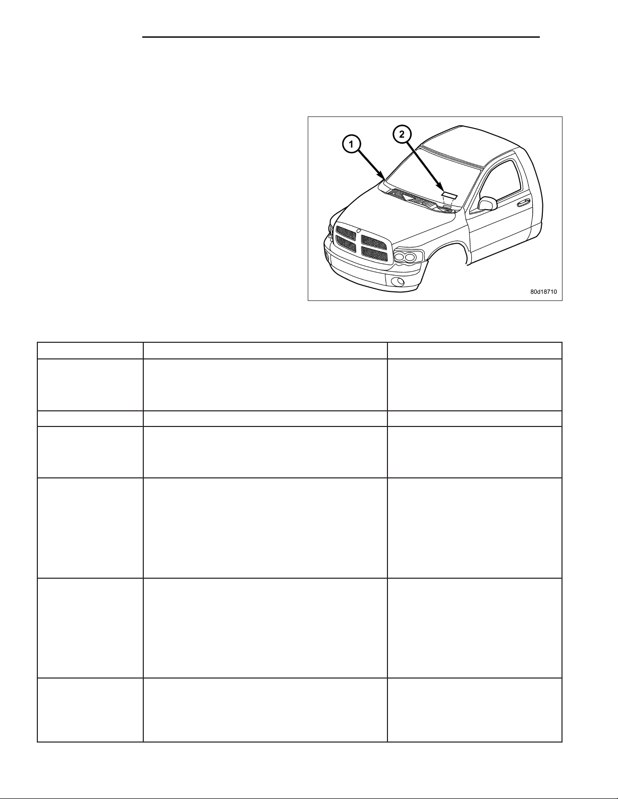
DESCRIPTION – VIN CODING/LOCATIONS
The Vehicle Identification Number (VIN) plate (2) is
located on the lower windshield fence near the left
a-pillar. The VIN contains 17 characters that provide
data concerning the vehicle. Refer to the VIN decoding chart to determine the identification of a vehicle.
The VIN is also imprinted on the:
• Body Code Plate.
• Equipment Identification Plate.
• Vehicle Safety Certification Label.
• Frame rail.
To protect the consumer from theft and possible fraud
the manufacturer is required to include a Check Digit
at the ninth position of the VIN. The check digit is
used by the manufacturer and government agencies
to verify the authenticity of the vehicle and official documentation. The formula to use the check digit is not released to the general public.
POSITION INTERPRETATION CODE = DESCRIPTION
1 Country of Origin 1 = Manufactured By
DaimlerChrysler Corporation
3 = Manufactured By
DaimlerChrysler De Mexico
2 Make D = Dodge
3 Vehicle Type 2 = Incomplete with Side Airbag
5 = Truck with Side Airbag
6 = Incomplete Less Side Airbag
7 = Truck Less Side Airbag
4 Gross Vehicle Weight Rating G = 5,001-6000 lbs.
H = 6,001-7,000 lbs.
J = 7,001-8,000 lbs.
K = 8,001-9,000 lbs.
L = 9,001-10,000 lbs.
M = 10,001-14,000 lbs.
W = Buses/Incomplete Vehicles with
Hydraulic Brakes
5 Vehicle Line A = Ram Pickup 1500 4X2
U = Ram Pickup 1500 4X4
R = Ram Pickup 2500 4X2
S = Ram Pickup 2500 4X4
N = Ram Cab Chassis 4X2 DX
Family
L = Ram Pickup 3500 4X2
X = Ram Pickup 3500 4X4
6 Series 1 = 1500
2 = 2500
3 = 3500 Less Dual Rear Wheels
4 = 3500 With Dual Rear Wheels
5 = 4000 DX Family
Page 3
DR INTRODUCTION 3
POSITION INTERPRETATION CODE = DESCRIPTION
7 Body Style 6 = Conventional Cab/Cab Chassis
8 = Quad Cab Full Rear Doors
9 = Mega Cab Ram Pickup
8 Engine K = 3.7L 6 cyl. MPI Gasoline
N = 4.7L 8 cyl. MPI Gasoline
P = 4.7L 8 cyl. Flex Fuel
D = 5.7L 8 cyl. SMPI Gasoline
C = 5.9L 6 cyl. Turbo Diesel High
Output
H = 8.3L 10 cyl. SFI Gasoline
9 Check Digit 0 through 9 or X
10 Model Year 6 = 2006
11 Plant Location S = Dodge City
G = Saltillo
J = St. Louis (North)
12 – 17 Vehicle Build Sequence
Page 4
4 INTRODUCTION DR
VEHICLE EMISSION CONTROL INFORMATION (VECI)
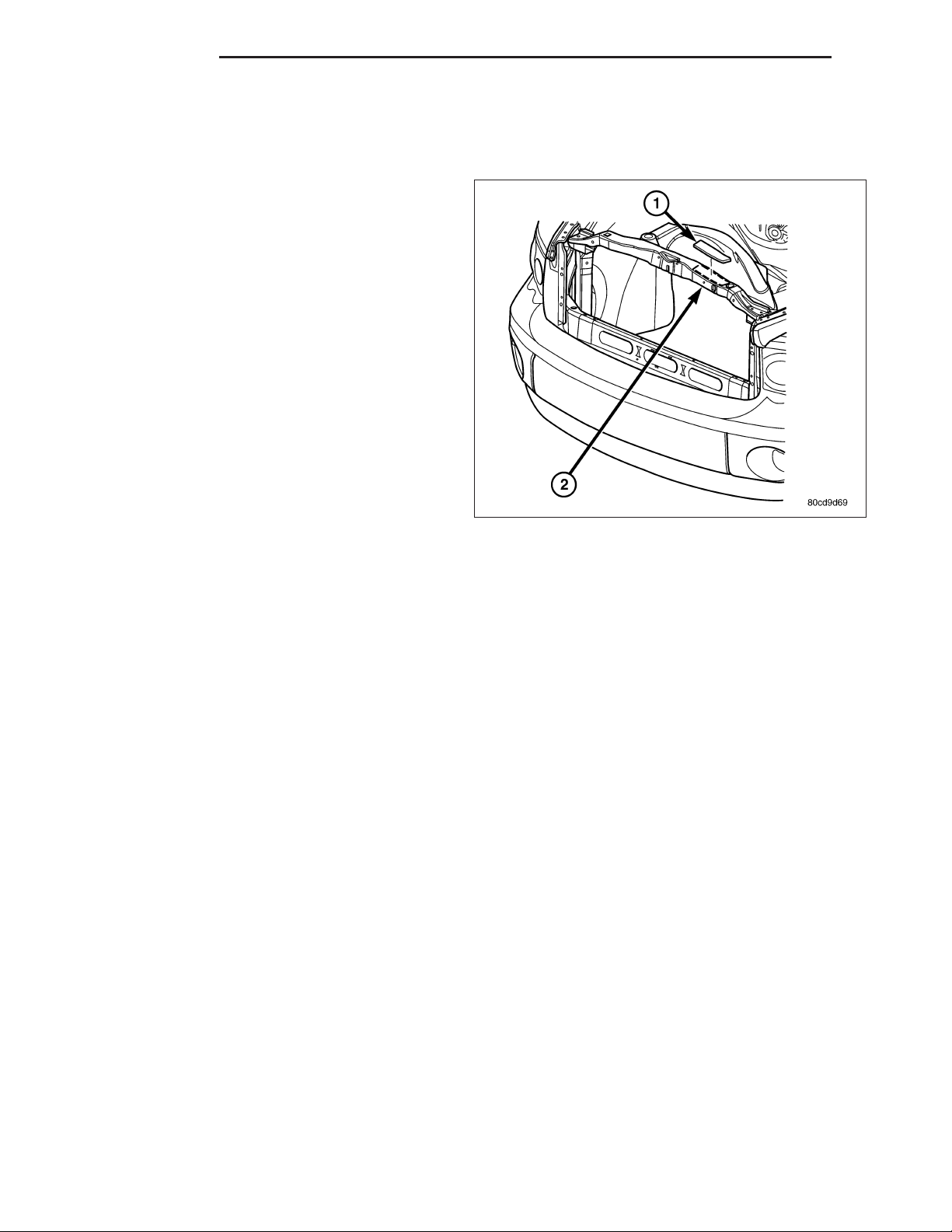
DESCRIPTION
All models have a Vehicle Emission Control Information (VECI) Label (1). DaimlerChrysler permanently
attaches the label in the engine compartment. The
label cannot be removed without defacing label information and destroying label.
The label contains the vehicle’s emission specifications and vacuum hose routings. All hoses must be
connected and routed according to the label.
The label also contains an engine vacuum schematic.
There are unique labels for vehicles built for sale in
the state of California and the country of Canada.
Canadian labels are written in both the English and
French languages.
The VECI label contains the following:
• Engine family and displacement
• Evaporative family
• Emission control system schematic
• Certification application
• Engine timing specifications (if adjustable)
• Idle speeds (if adjustable)
• Spark plug and gap
Page 5
DR INTRODUCTION 5
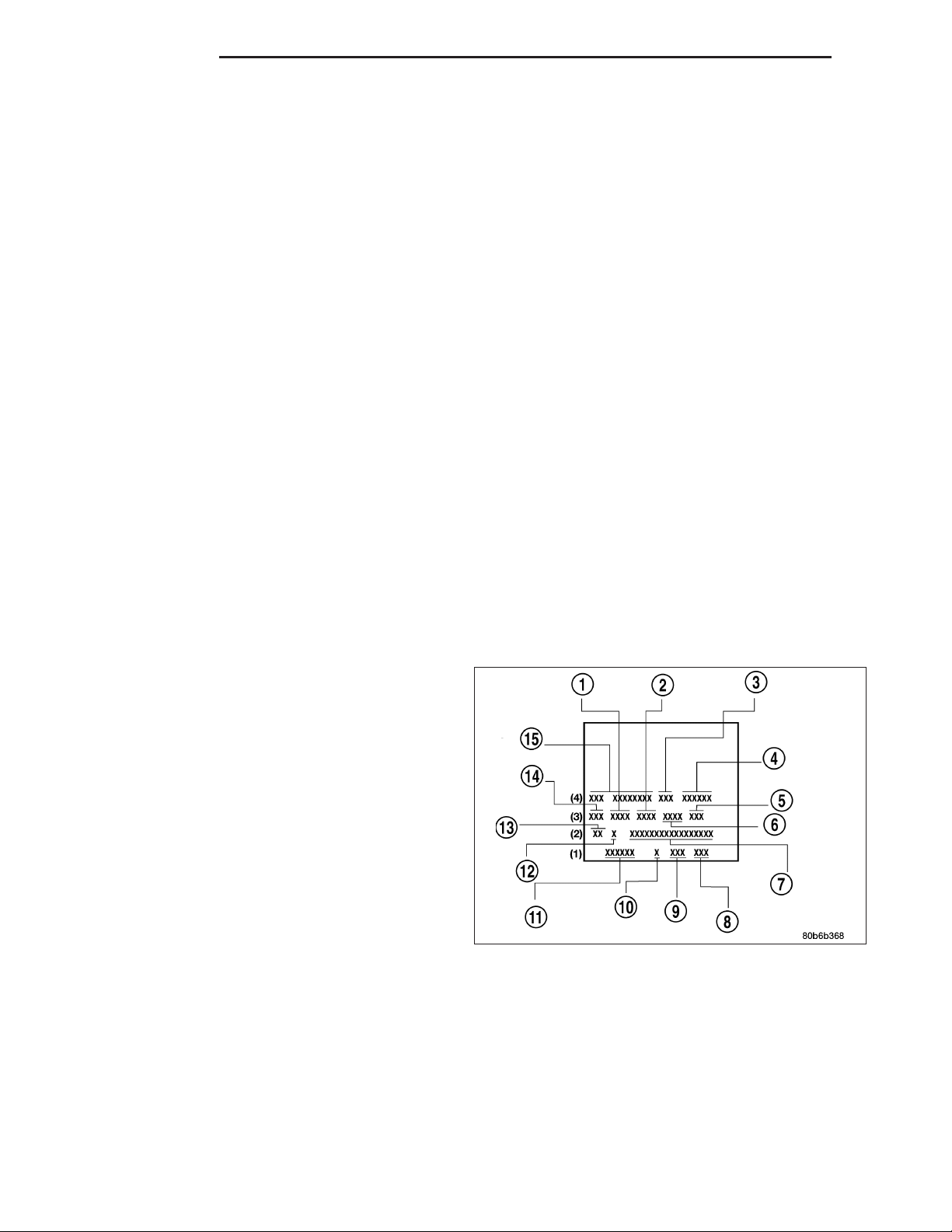
BODY CODE PLATE
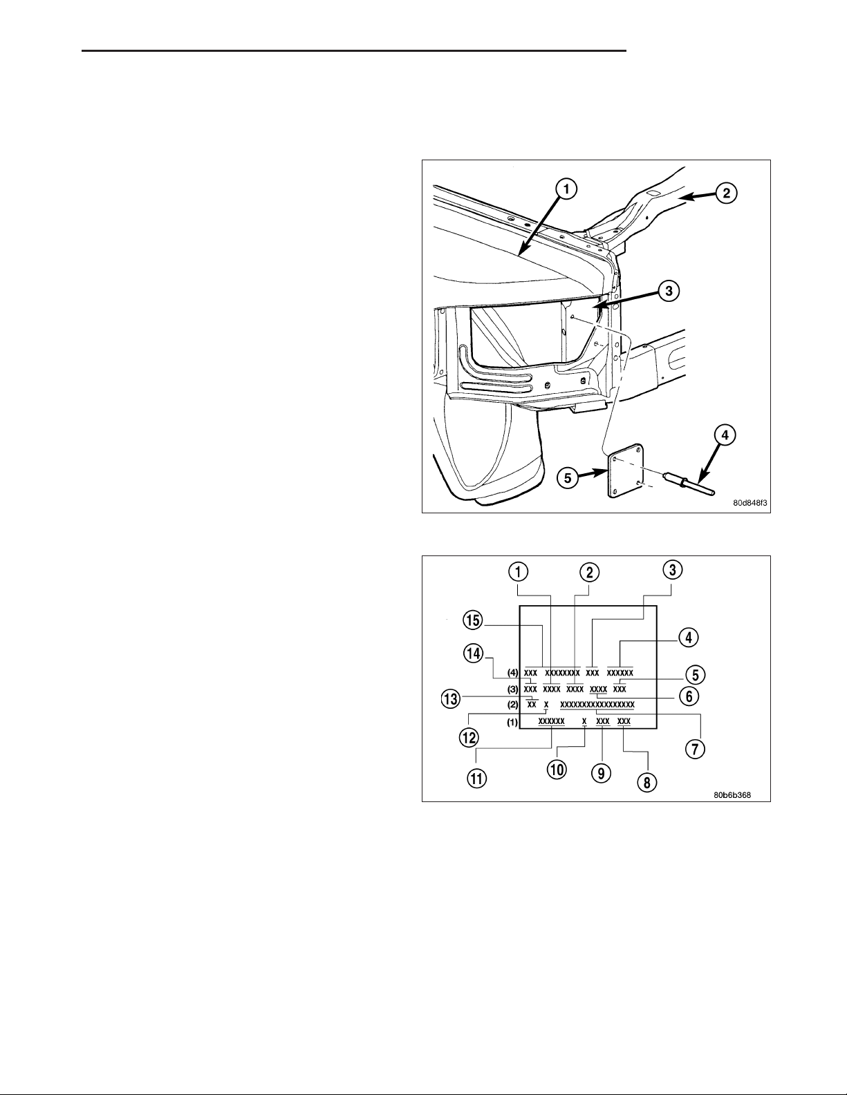
DESCRIPTION
The Body Code Plate is located on the right front
hydroform fender rail just behind the headlight assembly. There are seven lines of information on the body
code plate. Lines 5, 6, and 7 are not used to define
service information. Information reads from left to
right, starting with line 4 in the center of the plate to
line 1 at the bottom of the plate.
The last code imprinted on a vehicle code plate will be
followed by the imprinted word END. When two vehicle code plates are required, the last available spaces
on the first plate will be imprinted with the letters CTD
(for continued).
When a second vehicle code plate is necessary, the
first four spaces on each row will not be used
because of the plate overlap.
BODY CODE PLATE – LINE 4
DIGITS 1 THROUGH 12
Vehicle Order Number (15)
DIGITS 13, 14, AND 15
Transmission Codes (3)
• DDP = 5–speed Manual (NV4500)
• DEC = 6–speed Manual (NV5600)
• DEE = 6–speed Manual Tremec (T-56)
• DEG = 6–speed Manual (G56)
• DEJ = 6–speed Manual (GETRAG 238)
• DG4 = 4–speed Automatic (45RFE)
• DG8 = 4–speed Automatic (48RE)
• DGQ = 4–speed Automatic (5-45RFE)
DIGITS 16 and 17
Family (4)
• DR = 1500
• DH = 2500
• D1 = 3500
• DC = 3500 (Cab Chassis)
• DX = Mexico Work Truck
DIGIT 18
Vehicle Line (4)
Page 6
6 INTRODUCTION DR
2 - Wheel Drive
• 1 = 1500
• 2 = 2500
• 3 = 3500
4 - Wheel Drive
• 6 = 1500
• 7 = 2500
• 8 = 3500
DIGIT 19
Price Class (4)
• L = Low
• H = Highline
• P = Premium
• S=SRT-10
DIGITS 20 AND 21
Body Type (4)
• 41 = Ram Truck Quad Cab, 6.5’ Box
• 42 = Ram Truck Quad Cab, 8.0’ Box
• 61 = Ram Truck Standard Cab, 6.5’ Box
• 62 = Ram Truck Standard Cab, 8.0’ Box
• 81 = Ram Truck Mega Cab, 6.5’ Box
BODY CODE PLATE – LINE 3
DIGITS 1,2, AND 3
Paint Procedure (14)
• APA = Monotone
• AP9 = Special
• APD = Two-tone (Lower break)
DIGIT 4
Open Space
DIGITS 5 THROUGH 8
Primary Paint (1)
(Refer to 23 - BODY/PAINT - SPECIFICATIONS) for
color codes.
DIGIT 9
Open Space
DIGITS 10 THROUGH 13
Secondary Paint (2)
DIGIT 14
Open Space
Page 7

DR INTRODUCTION 7
DIGITS 15 THROUGH 18
Interior Trim Code (6)
DIGIT 19
Open Space
DIGITS 20, 21, AND 22
Engine Code (5)
• EKG = 3.7L 6 cyl. MPI Gasoline
• EVA = 4.7L 8 cyl. MPI Gasoline
• EVD = 4.7L 8 cyl. Flex Fuel
• EZA = 5.7L 8 cyl. SMPI Gasoline
• ETH = 5.9L 6 cyl. Cummins Turbo Diesel High Output
• EWC = 8.3L 19 cyl. SFI Gasoline
BODY CODE PLATE – LINE 2
DIGIT 1 Open Space
DIGITS 2 AND 3 Species Code. (Used for
Manufacturing) (13)
DIGIT 4
Open Space
DIGIT 5
Market Code (12)
• B = International
• C = Canada
• M = Mexico
• U = United States
DIGIT 6
Open Space
DIGITS 7 THROUGH 23
Vehicle Identification Number (VIN) (7)
(Refer to VEHICLE DATA/VEHICLE INFORMATION/VEHICLE IDENTIFICATION NUMBER - DESCRIPTION) for
proper breakdown of VIN code.
Page 8

8 INTRODUCTION DR
BODY CODE PLATE – LINE 1
DIGITS 1 THROUGH 6 Body-in-white assembly
sequence (11)
DIGIT 7
Open Space
DIGIT 8 Tailgate trim code (10)
DIGIT 9
Open Space
DIGITS 10 THROUGH 12 Cargo box code (9)
DIGIT 13
Open Space
DIGITS 14 THROUGH 16 Tailgate code (8)
Page 9

DR INTRODUCTION 9
INTERNATIONAL VEHICLE CONTROL & DISPLAY SYMBOLS
DESCRIPTION - INTERNATIONAL SYMBOLS
The graphic symbols illustrated in the following International Control and Display Symbols Chart are used to identify
various instrument controls. The symbols correspond to the controls and displays that are located on the instrument
panel.
Page 10

10 INTRODUCTION DR
FASTENER IDENTIFICATION
DESCRIPTION
The SAE bolt strength grades range from grade 2 to grade 8. The higher the grade number, the greater the bolt
strength. Identification is determined by the line marks on the top of each bolt head. The actual bolt strength grade
corresponds to the number of line marks plus 2. The most commonly used metric bolt strength classes are 9.8 and
10.9. The metric strength class identification number is imprinted on the head of the bolt. The higher the class
number, the greater the bolt strength. Some metric nuts are imprinted with a single-digit strength class on the nut
face. Refer to the Fastener Identification and Fastener Strength Charts.
Bolt Markings and Torques - Metric
Bolt Markings 8.8/8.9 10.9 12.9
Bolt Dia. N·m Ft. Lbs. N·m Ft. Lbs. N·m Ft. Lbs.
6 12 105* 14 120* 16 12
8 25 250* 32 23 38 28
10 54 40 60 45 74 55
12 95 70 108 80 135 100
14 155 115 175 130 216 160
16 243 180 324 210 324 240
* Inch Lbs.
Bolt Markings and Torques - U. S. Customary
Bolt Markings Grade 5 Grade 8
Bolt Dia. N·m Ft. Lbs N·m Ft. Lbs
1/4 - 20 10 95* 14 125*
1/4 - 28 10 95* 17 150*
5/16 - 18 22 200* 30 270*
5/16 - 24 26 240* 33 300*
3/8-1640305540
3/8-2447356045
7/16-1468508865
7/16-2074559570
1/2 - 13 101 75 135 100
1/2 -20 115 85 150 110
9/16 - 12 135 105 182 135
9/16 - 18 155 115 202 150
5/8 - 11 202 150 263 195
5/8 - 18 215 160 284 210
3/4 - 10 230 170 297 220
3/4 - 16 236 175 304 225
7/8 - 14 405 300 540 400
* Inch Lbs.
Page 11

DR INTRODUCTION 11
Page 12

12 INTRODUCTION DR
FASTENER USAGE
DESCRIPTION
FASTENER USAGE
WARNING: Use of an incorrect fastener may result in component damage or personal injury.
Fasteners and torque specifications references in this Service Manual are identified in metric and SAE format.
During any maintenance or repair procedures, it is important to salvage all fasteners (nuts, bolts, etc.) for reassem-
bly. If the fastener is not salvageable, a fastener of equivalent specification must be used.
Page 13

DR INTRODUCTION 13
THREADED HOLE REPAIR
DESCRIPTION
THREADED HOLE REPAIR
Most stripped threaded holes can be repaired using a HelicoilT. Follow the vehicle or HelicoilT recommendations for
application and repair procedures.
Page 14

14 INTRODUCTION DR
METRIC SYSTEM
DESCRIPTION
The metric system is based on quantities of one, ten, one hundred, one thousand and one million.
The following chart will assist in converting metric units to equivalent English and SAE units, or vise versa.
Page 15

DR INTRODUCTION 15
CONVERSION FORMULAS AND EQUIVALENT VALUES
MULTIPLY BY TO GET MULTIPLY BY TO GET
in-lbs x
0.11298
ft-lbs x
1.3558
Inches Hg (60° F) x 3.377 = Kilopascals (kPa) kPa x
psi x 6.895 = Kilopascals (kPa) kPa x 0.145 = psi
Inches x 25.4 = Millimeters (mm) mm x
Feet x
0.3048
Yards x
0.9144
mph x
1.6093
Feet/Sec x
0.3048
mph x
0.4470
Kilometers/Hr. (Km/h) x
0.27778
= Newton Meters
(N·m)
= Newton Meters
(N·m)
= Meters (M) M x 3.281 = Feet
= Meters M x
= Kilometers/Hr.
(Km/h)
= Meters/Sec (M/S) M/S x 3.281 = Feet/Sec
= Meters/Sec (M/S) M/S x 2.237 = mph
= Meters/Sec (M/S) M/S x 3.600 Kilometers/Hr. (Km/h)
N·m x 8.851 = in-lbs
N·m x
0.7376
0.2961
0.03937
1.0936
Km/h x
0.6214
= ft-lbs
= Inches Hg
= Inches
= Yards
= mph
COMMON METRIC EQUIVALENTS
1 inch = 25 Millimeters 1 Cubic Inch = 16 Cubic Centimeters
1 Foot = 0.3 Meter 1 Cubic Foot = 0.03 Cubic Meter
1 Yard = 0.9 Meter 1 Cubic Yard = 0.8 Cubic Meter
1 Mile = 1.6 Kilometers
Refer to the Metric Conversion Chart to convert torque values listed in metric Newton- meters (N·m). Also, use the
chart to convert between millimeters (mm) and inches (in.).
Page 16

16 INTRODUCTION DR
TORQUE REFERENCES
DESCRIPTION
Individual Torque Charts appear within many or the Groups. Refer to the Standard Torque Specifications Chart for
torque references not listed in the individual torque charts.
Page 17

DR INTRODUCTION 17
VEHICLE CERTIFICATION LABEL
DESCRIPTION
A vehicle certification label is attached to every
DaimlerChrysler Corporation vehicle. The label certifies that the vehicle conforms to all applicable Federal
Motor Vehicle Standards. The label also lists:
• Month and year of vehicle manufacture.
• Gross Vehicle Weight Rating (GVWR). The gross
front and rear axle weight ratings (GAWR’s) are
based on a minimum rim size and maximum cold
tire inflation pressure.
• Vehicle Identification Number (VIN).
• Type of vehicle.
• Type of rear wheels.
• Bar code.
• Month, Day and Hour (MDH) of final assembly.
• Paint and Trim codes.
• Country of origin.
The label is located on the driver-side door shut-face.
Page 18

 Loading...