

Page 1

DR INSTRUMENT CLUSTER 8J - 1
INSTRUMENT CLUSTER
TABLE OF CONTENTS
page page
INSTRUMENT CLUSTER
DESCRIPTION ..........................2
OPERATION ............................6
DIAGNOSIS AND TESTING - INSTRUMENT
CLUSTER ...........................10
REMOVAL .............................14
DISASSEMBLY .........................14
ASSEMBLY ............................15
INSTALLATION .........................16
ABS INDICATOR
DESCRIPTION .........................17
OPERATION ...........................17
AIRBAG INDICATOR
DESCRIPTION .........................18
OPERATION ...........................18
BRAKE/PARK BRAKE INDICATOR
DESCRIPTION .........................18
OPERATION ...........................19
DIAGNOSIS AND TESTING - BRAKE
INDICATOR ..........................19
CARGO LAMP INDICATOR
DESCRIPTION .........................20
OPERATION ...........................20
CHECK GAUGES INDICATOR
DESCRIPTION .........................21
OPERATION ...........................21
CRUISE INDICATOR
DESCRIPTION .........................22
OPERATION ...........................22
DOOR AJAR INDICATOR
DESCRIPTION .........................23
OPERATION ...........................23
ENGINE TEMPERATURE GAUGE
DESCRIPTION .........................23
OPERATION ...........................23
ETC INDICATOR
DESCRIPTION .........................24
OPERATION ...........................25
FUEL GAUGE
DESCRIPTION .........................25
OPERATION ...........................26
GEAR SELECTOR INDICATOR
DESCRIPTION .........................26
OPERATION ...........................27
HIGH BEAM INDICATOR
DESCRIPTION .........................27
OPERATION ...........................28
LAMP OUT INDICATOR
DESCRIPTION .........................28
OPERATION ...........................28
LOW FUEL INDICATOR
DESCRIPTION .........................29
OPERATION ...........................29
MALFUNCTION INDICATOR LAMP (MIL)
DESCRIPTION .........................30
OPERATION ...........................30
ODOMETER
DESCRIPTION .........................31
OPERATION ...........................31
OIL PRESSURE GAUGE
DESCRIPTION .........................32
OPERATION ...........................32
OVERDRIVE OFF INDICATOR
DESCRIPTION .........................33
OPERATION ...........................33
SEATBELT INDICATOR
DESCRIPTION .........................34
OPERATION ...........................34
SECURITY INDICATOR
DESCRIPTION .........................34
OPERATION ...........................35
SERVICE 4WD INDICATOR
DESCRIPTION .........................35
OPERATION ...........................36
SPEEDOMETER
DESCRIPTION .........................36
OPERATION ...........................36
TACHOMETER
DESCRIPTION .........................37
OPERATION ...........................37
TRANS TEMP INDICATOR
DESCRIPTION .........................38
OPERATION ...........................38
TURN SIGNAL INDICATOR
DESCRIPTION .........................39
OPERATION ...........................39
UPSHIFT INDICATOR
DESCRIPTION .........................40
OPERATION ...........................40
VOLTAGE GAUGE
DESCRIPTION .........................40
OPERATION ...........................41
WAIT-TO-START INDICATOR
DESCRIPTION .........................42
OPERATION ...........................42
Page 2
8J - 2 INSTRUMENT CLUSTER DR
WASHER FLUID INDICATOR
DESCRIPTION .........................42
OPERATION ...........................42
INSTRUMENT CLUSTER
DESCRIPTION
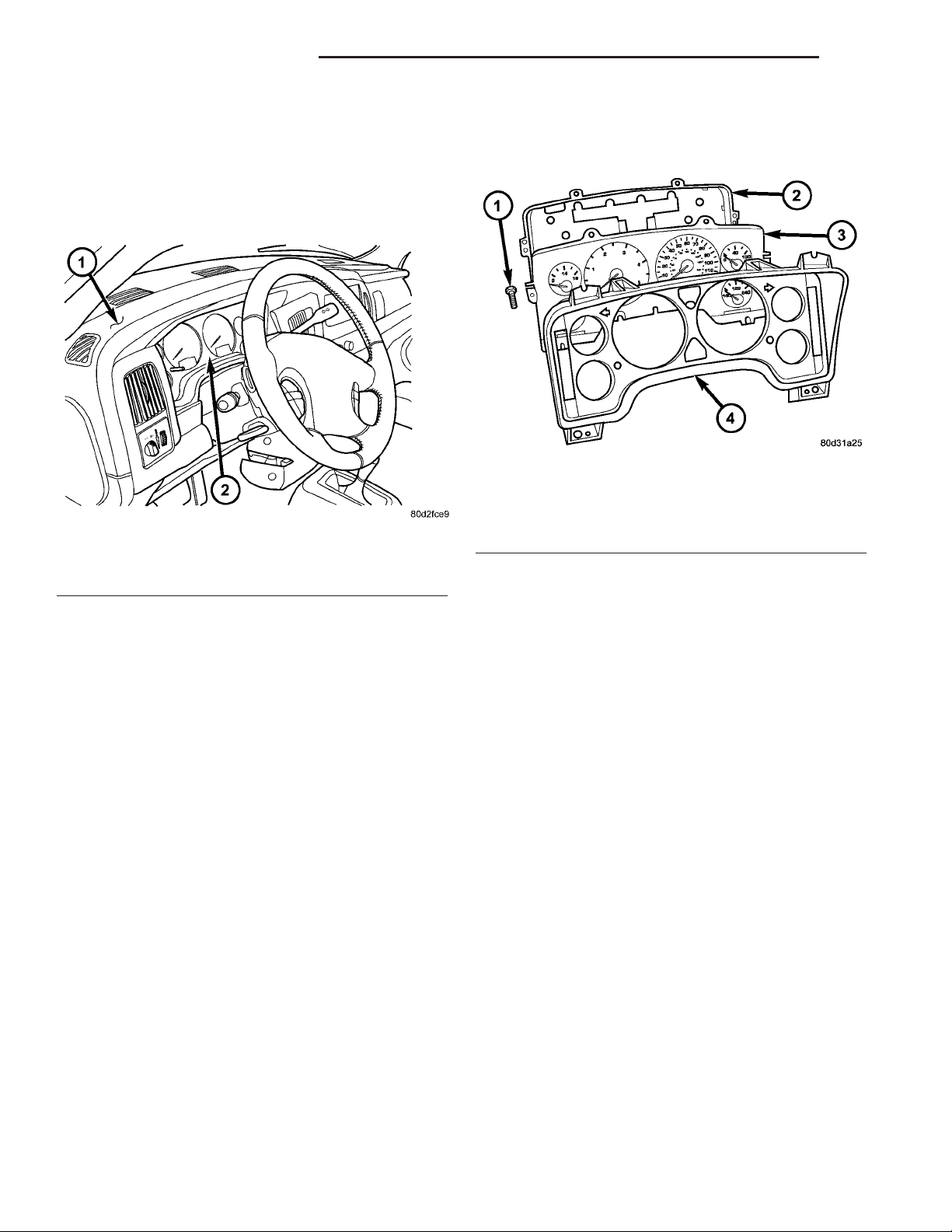
Fig. 1 Instrument Cluster
1 - INSTRUMENT PANEL
2 - INSTRUMENT CLUSTER
The instrument cluster for this model is an ElectroMechanical Instrument Cluster (EMIC) that is
located in the instrument panel above the steering
column opening, directly in front of the driver (Fig.
1). The remainder of the EMIC, including the mounts
and the electrical connections, are concealed within
the instrument panel behind the cluster bezel.
Besides analog gauges and indicators, the EMIC
module incorporates two blue-green digital Vacuum
Fluorescent Display (VFD) units for displaying odometer/trip odometer information, engine hours, automatic transmission gear selector position (PRNDL),
several warning or reminder indications and certain
diagnostic information. The instrument cluster for
this model also includes the hardware and software
necessary to serve as the electronic body control module and is sometimes referred to as the Cab Compartment Node or CCN.
The EMIC gauges and indicators are visible
through a dedicated opening in the cluster bezel on
the instrument panel and are protected by a clear
plastic cluster lens (Fig. 2) that is integral to a cluster lens, hood and mask unit. Just behind the cluster
lens is the cluster hood and an integral cluster mask,
which are constructed of molded black plastic. The
cluster hood serves as a visor and shields the face of
the cluster from ambient light and reflections to
reduce glare, while the cluster mask serves to separate and define the individual gauges and indicators
of the EMIC. A black plastic odometer/trip odometer
WATER-IN-FUEL INDICATOR
DESCRIPTION .........................43
OPERATION ...........................43
Fig. 2 Instrument Cluster Components
1 - SCREW (9)
2 - REAR COVER
3 - CLUSTER HOUSING
4 - LENS, HOOD & MASK
switch button protrudes through dedicated holes in
the cluster mask and the cluster lens, located near
the lower edge of the cluster just to the left of the
tachometer. The molded plastic EMIC lens, hood and
mask unit has four integral mounting tabs, one each
on the upper and lower outboard corners of the unit.
These mounting tabs are used to secure the EMIC to
the molded plastic instrument panel cluster carrier
with four screws.
The rear of the cluster housing and the EMIC electronic circuitry are protected by a molded plastic rear
cover, which is secured to the cluster housing with a
single screw, while eight screws installed around the
outside perimeter of the rear cover secure it to the
cluster lens, hood and mask unit. The rear cover
includes clearance holes for service access to each of
the eleven incandescent bulb and bulb holder units
installed on the cluster circuit board for general illumination lighting and for the cluster connector receptacles. The connector receptacles on the back of the
cluster electronic circuit board connect the EMIC to
the vehicle electrical system through three take outs
with connectors from the instrument panel wire harness. The EMIC also has an integral interface connector on the back of the cluster circuit board that
joins it to the optional external RKE receiver through
a connector receptacle that is integral to that unit.
The rear cover includes a molded receptacle and two
latch features to secure the RKE receiver on vehicles
that are so equipped.
Sandwiched between the rear cover and the lens,
hood and mask unit is the cluster housing. The
Page 3

DR INSTRUMENT CLUSTER 8J - 3
INSTRUMENT CLUSTER (Continued)
molded plastic cluster housing serves as the carrier
for the cluster circuit board and circuitry, the cluster
connector receptacles, the RKE interface connector,
the gauges, a Light Emitting Diode (LED) for each
cluster indicator, two VFD units, an audible tone
generator, the cluster overlay, the gauge pointers, the
odometer/trip odometer switch and the switch button.
The cluster overlay is a laminated plastic unit. The
dark, visible, outer surface of the overlay is marked
with all of the gauge dial faces and graduations, but
this layer is also translucent. The darkness of this
outer layer prevents the cluster from appearing cluttered or busy by concealing the cluster indicators
that are not illuminated, while the translucence of
this layer allows those indicators and icons that are
illuminated to be readily visible. The underlying
layer of the overlay is opaque and allows light from
the LED for each of the various indicators and the
incandescent illumination lamps behind it to be visible through the outer layer of the overlay only
through predetermined stencil-like cutouts. A rectangular opening in the overlay at the base of both the
speedometer and tachometer dial faces has a smoked
clear lens through which the illuminated VFD units
can be viewed.
Several versions of the EMIC module are offered
on this model. These versions accommodate all of the
variations of optional equipment and regulatory
requirements for the various markets in which the
vehicle will be offered. The microprocessor-based
EMIC utilizes integrated circuitry and information
carried on the Programmable Communications Interface (PCI) data bus network along with several hard
wired analog and multiplexed inputs to monitor sensors and switches throughout the vehicle. In response
to those inputs, the internal circuitry and programming of the EMIC allow it to control and integrate
many electronic functions and features of the vehicle
through both hard wired outputs and the transmission of electronic message outputs to other electronic
modules in the vehicle over the PCI data bus. (Refer
to 8 - ELECTRICAL/ELECTRONIC CONTROL
MODULES/COMMUNICATION - DESCRIPTION PCI BUS).
Besides typical instrument cluster gauge and indicator support, the electronic functions and features
that the EMIC supports or controls include the following:
• Audible Warnings - The EMIC electronic cir-
cuit board is equipped with an audible tone generator
and programming that allows it to provide various
audible alerts to the vehicle operator, including
chime tones and beep tones. An electromechanical
relay is also soldered onto the circuit board to produce audible clicks that emulate the sound of a conventional turn signal or hazard warning flasher.
(Refer to 8 - ELECTRICAL/CHIME/BUZZER DESCRIPTION).
• Brake Lamp Control - The EMIC provides
electronic brake lamp request messages to the Front
Control Module (FCM) located on the Integrated
Power Module (IPM) for brake lamp control, excluding control of the Center High Mounted Stop Lamp
(CHMSL), which remains controlled by a direct hard
wired output of the brake lamp switch.
• Brake Transmission Shift Interlock Control
- The EMIC monitors inputs from the brake lamp
switch, ignition switch, and the Transmission Range
Sensor (TRS), then controls a high-side driver output
to operate the Brake Transmission Shift Interlock
(BTSI) solenoid that locks and unlocks the automatic
transmission gearshift selector lever on the steering
column.
• Cargo Lamp Control - The EMIC provides
direct control of cargo lamp operation with a load
shedding (battery saver) feature which will automatically turn off the cargo lamp if it remains on after a
timed interval.
• Central Locking - The EMIC provides support
for the central locking feature of the power lock system. This feature will lock or unlock all doors based
upon the input from the door cylinder lock switch.
Door cylinder lock switches are used only on models
equipped with the optional Vehicle Theft Security
System (VTSS).
• Door Lock Inhibit - The EMIC inhibits locking
of the doors with the power lock switch when the key
is in the ignition switch and the driver side front
door is ajar. However, operation of the door locks is
not inhibited under the same conditions when the
Lock button of the optional RKE transmitter is
depressed.
• Enhanced Accident Response - The EMIC
monitors an input from the Airbag Control Module
(ACM) and, following an airbag deployment, will
immediately disable the power lock output, unlock all
doors by activating the power unlock output, then
enables the power lock output if the power lock
switch input remains inactive for two seconds. This
feature, like all other enhanced accident response
features, is dependent upon a functional vehicle electrical system following the vehicle impact event.
• Exterior Lighting Control - The EMIC pro-
vides electronic head lamp and/or park lamp request
messages to the Front Control Module (FCM) located
on the Integrated Power Module (IPM) for the appropriate exterior lamp control of standard head and
park lamps, as well as optional front fog lamps. This
includes support for headlamp beam selection and
the optical horn feature, also known as flash-to-pass.
• Exterior Lighting Fail-safe - In the absence of
a headlamp switch input, the EMIC will turn on the
Page 4

8J - 4 INSTRUMENT CLUSTER DR
INSTRUMENT CLUSTER (Continued)
cluster illumination lamps and provide electronic
headlamp low beam and park lamp request messages
to the Front Control Module (FCM) located on the
Integrated Power Module (IPM) for default exterior
lamp operation. The FCM will also provide default
park lamp and headlamp low beam operation and the
EMIC will turn on the cluster illumination lamps if
there is a failure of the electronic data bus communication between the EMIC and the FCM.
• Heated Seat Control - The EMIC monitors
inputs from the ignition switch and electronic engine
speed messages from the Powertrain Control Module
(PCM) to control a high side driver output to the
heated seat switch Light Emitting Diode (LED) indicators. This input allows the heated seat switches to
wake up the heated seat module if the switch is actuated. The EMIC will de-energize the heated seat
switch LED indicators, which deactivates the heated
seat system, if the ignition switch is turned to any
position except On or Start, or if the engine speed
message indicates zero. (Refer to 8 - ELECTRICAL/
HEATED SEATS - DESCRIPTION).
• Interior Lamp Load Shedding - The EMIC
provides a battery saver feature which will automatically turn off all interior lamps that remain on after
a timed interval of about fifteen minutes.
• Interior Lamps - Enhanced Accident
Response - The EMIC monitors inputs from the Air-
bag Control Module (ACM) and the Powertrain Control Module (PCM) to automatically turn on the
interior lighting after an airbag deployment event
ten seconds after the vehicle speed is zero. The interior lighting remains illuminated until the ignition
switch is turned to the Off position, at which time
the interior lighting returns to normal operation and
control. This feature, like all other enhanced accident
response features, is dependent upon a functional
vehicle electrical system following the vehicle impact
event.
• Interior Lighting Control - The EMIC moni-
tors inputs from the interior lighting switch, the door
ajar switches, the cargo lamp switch, the reading
lamp switches, and the Remote Keyless Entry (RKE)
module to provide courtesy lamp control. This
includes support for timed illuminated entry with
theater-style fade-to-off and courtesy illumination
defeat features.
• Lamp Out Indicator Control - The EMIC
monitors electronic lamp outage messages from the
Front Control Module (FCM) located on the Integrated Power Module (IPM) in order to provide lamp
out indicator control for the headlamps (low and high
beams), turn signal lamps, and the brake lamps
(excluding CHMSL).
• Panel Lamps Dimming Control - The EMIC
provides a hard wired 12-volt Pulse-Width Modulated
(PWM) output that synchronizes the dimming level
of all panel lamps dimmer controlled lamps with that
of the cluster illumination lamps.
• Parade Mode - The EMIC provides a parade
mode (also known as funeral mode) that allows all
Vacuum-Fluorescent Display (VFD) units in the vehicle to be illuminated at full (daytime) intensity while
driving during daylight hours with the exterior
lamps turned on.
• Power Locks - The EMIC monitors inputs from
the power lock switches and the Remote Keyless
Entry (RKE) receiver module (optional) to provide
control of the power lock motors through high side
driver outputs to the power lock motors. This
includes support for rolling door locks (also known as
automatic door locks), automatic door unlock, a door
lock inhibit mode, and central locking (with the
optional Vehicle Theft Security System only). (Refer
to 8 - ELECTRICAL/POWER LOCKS - DESCRIPTION).
• Remote Keyless Entry - The EMIC supports
the optional Remote Keyless Entry (RKE) system features, including support for the RKE Lock, Unlock
(with optional driver-door-only unlock, and unlockall-doors), Panic, audible chirp, optical chirp, illuminated entry modes, an RKE programming mode, as
well as optional Vehicle Theft Security System
(VTSS) arming (when the proper VTSS arming conditions are met) and disarming.
• Remote Radio Switch Interface - The EMIC
monitors inputs from the optional remote radio
switches and then provides the appropriate electronic
data bus messages to the radio to select the radio
operating mode, volume control, preset station scan
and station seek features.
• Rolling Door Locks - The EMIC provides sup-
port for the power lock system rolling door locks feature (also known as automatic door locks). This
feature will automatically lock all unlocked doors
each time the vehicle speed reaches twenty-four kilometers-per-hour (fifteen miles-per-hour) and, following an automatic lock event, will automatically
unlock all doors once the ignition is turned to the Off
position and the driver side front door is opened.
• Turn Signal & Hazard Warning Lamp Control - The EMIC provides electronic turn and hazard
lamp request messages to the Front Control Module
(FCM) located on the Integrated Power Module (IPM)
for turn and hazard lamp control. The EMIC also
provides an audible click at one of two rates to emulate normal and bulb out turn or hazard flasher operation based upon electronic lamp outage messages
from the FCM, and provides an audible turn signal
on chime warning if a turn is signalled continuously
for more than about 1.6 kilometers (one mile) and
Page 5

DR INSTRUMENT CLUSTER 8J - 5
INSTRUMENT CLUSTER (Continued)
the vehicle speed remains greater than about twentyfour kilometers-per-hour (fifteen miles-per-hour).
• Vacuum Fluorescent Display Synchroniza-
tion - The EMIC transmits electronic panel lamp
dimming level messages which allows all other electronic modules on the PCI data bus with Vacuum
Fluorescent Display (VFD) units to coordinate their
illumination intensity with that of the EMIC VFD
units.
• Vehicle Theft Security System - The EMIC
monitors inputs from the door cylinder lock switch(es), the door ajar switches, the ignition switch, and
the Remote Keyless Entry (RKE) receiver module,
then provides electronic horn and lighting request
messages to the Front Control Module (FCM) located
on the Integrated Power Module (IPM) for the appropriate VTSS alarm output features.
• Wiper/Washer System Control - The EMIC
provides electronic wiper and/or washer request messages to the Front Control Module (FCM) located on
the Integrated Power Module (IPM) for the appropriate wiper and washer system features. (Refer to 8 ELECTRICAL/WIPERS/WASHERS - DESCRIPTION).
The EMIC houses six analog gauges and has provisions for up to twenty-three indicators (Fig. 3) or
(Fig. 4). The EMIC includes the following analog
gauges:
• Coolant Temperature Gauge
• Fuel Gauge
• Oil Pressure Gauge
• Speedometer
• Tachometer
• Voltage Gauge
Some of the EMIC indicators are automatically
configured when the EMIC is connected to the vehicle electrical system for compatibility with certain
optional equipment or equipment required for regulatory purposes in certain markets. While each EMIC
may have provisions for indicators to support every
available option, the configurable indicators will not
be functional in a vehicle that does not have the
equipment that an indicator supports. The EMIC
includes provisions for the following indicators (Fig.
3) or (Fig. 4):
• Airbag Indicator (with Airbag System only)
• Antilock Brake System (ABS) Indicator
(with ABS or Rear Wheel Anti-Lock [RWAL]
brakes only)
• Brake Indicator
• Cargo Lamp Indicator
• Check Gauges Indicator
• Cruise Indicator (with Speed Control only)
• Door Ajar Indicator
• Electronic Throttle Control (ETC) Indicator
(with 5.7L Gasoline Engine only)
• Gear Selector Indicator (with Automatic
Transmission only)
• High Beam Indicator
• Lamp Out Indicator
• Low Fuel Indicator
• Malfunction Indicator Lamp (MIL)
• Overdrive-Off Indicator (with Automatic
Transmission only)
• Seatbelt Indicator
• Security Indicator (with Sentry Key Immo-
bilizer & Vehicle Theft Security Systems only)
• Service Four-Wheel Drive Indicator (with
Four-Wheel Drive only)
• Transmission Overtemp Indicator (with
Automatic Transmission only)
• Turn Signal (Right and Left) Indicators
• Upshift Indicator (with Manual Transmis-
sion only)
• Washer Fluid Indicator
• Wait-To-Start Indicator (with Diesel Engine
only)
• Water-In-Fuel Indicator (with Diesel Engine
only)
Each indicator in the EMIC, except those located
within one of the VFD units, is illuminated by a dedicated LED that is soldered onto the EMIC electronic
circuit board. The LED units are not available for
service replacement and, if damaged or faulty, the
entire EMIC must be replaced. Cluster illumination
is accomplished by dimmable incandescent back
lighting, which illuminates the gauges for visibility
when the exterior lighting is turned on. Each of the
incandescent bulbs is secured by an integral bulb
holder to the electronic circuit board from the back of
the cluster housing.
Hard wired circuitry connects the EMIC to the
electrical system of the vehicle. These hard wired circuits are integral to several wire harnesses, which
are routed throughout the vehicle and retained by
many different methods. These circuits may be connected to each other, to the vehicle electrical system
and to the EMIC through the use of a combination of
soldered splices, splice block connectors, and many
different types of wire harness terminal connectors
and insulators. Refer to the appropriate wiring information. The wiring information includes wiring diagrams, proper wire and connector repair procedures,
further details on wire harness routing and retention, as well as pin-out and location views for the
various wire harness connectors, splices and grounds.
The EMIC modules for this model are serviced only
as complete units. The EMIC module cannot be
adjusted or repaired. If a gauge, an LED indicator, a
VFD unit, the electronic circuit board, the circuit
board hardware, the cluster overlay, or the EMIC
housing are damaged or faulty, the entire EMIC mod-
Page 6
8J - 6 INSTRUMENT CLUSTER DR
INSTRUMENT CLUSTER (Continued)
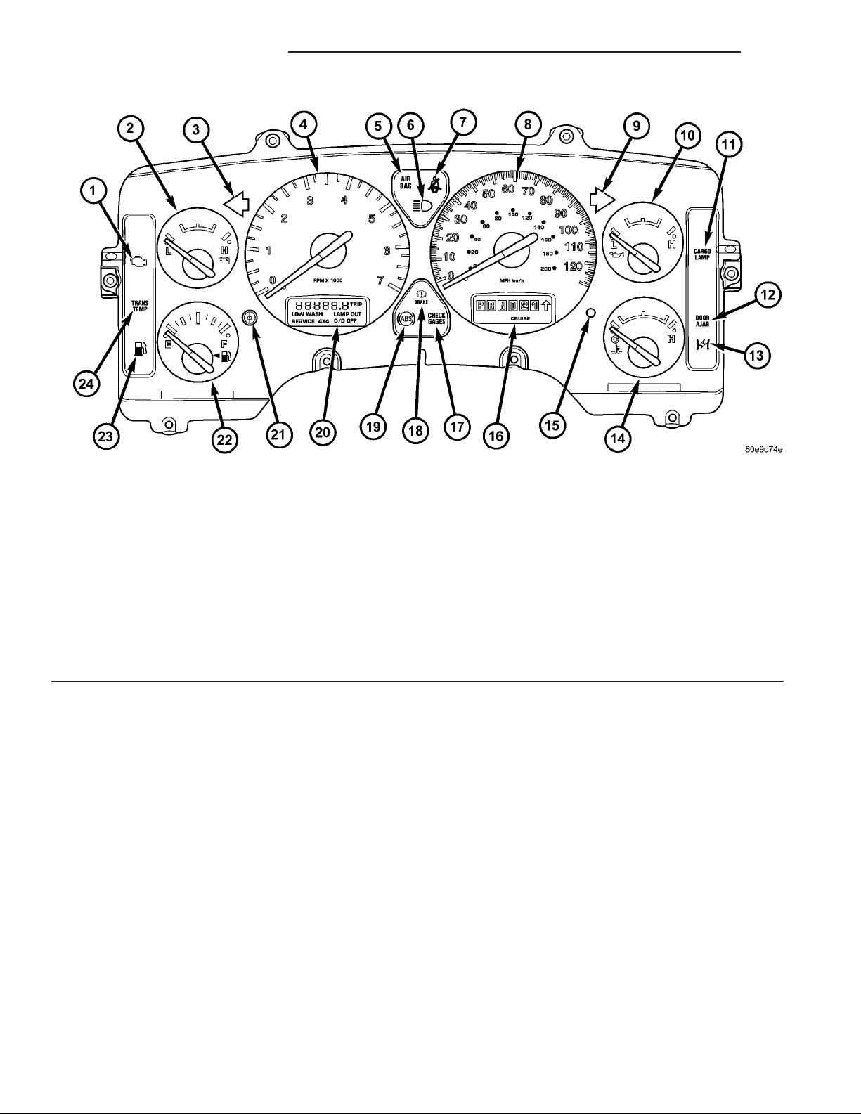
Fig. 3 Gauges & Indicators - Gasoline Engine
1 - MALFUNCTION INDICATOR LAMP 13 - ELECTRONIC THROTTLE CONTROL (ETC) INDICATOR
2 - VOLTAGE GAUGE 14 - ENGINE TEMPERATURE GAUGE
3 - LEFT TURN INDICATOR 15 - SECURITY INDICATOR
4 - TACHOMETER 16 - GEAR SELECTOR INDICATOR DISPLAY (INCLUDES
5 - AIRBAG INDICATOR 17 - CHECK GAUGES INDICATOR
6 - HIGH BEAM INDICATOR 18 - BRAKE INDICATOR
7 - SEATBELT INDICATOR 19 - ABS INDICATOR
8 - SPEEDOMETER 20 - ODOMETER/TRIP ODOMETER DISPLAY (INCLUDES
9 - RIGHT TURN INDICATOR 21 - ODOMETER/TRIP ODOMETER SWITCH BUTTON
10 - OIL PRESSURE GAUGE 22 - FUEL GAUGE
11 - CARGO LAMP INDICATOR 23 - LOW FUEL INDICATOR
12 - DOOR AJAR INDICATOR 24 - TRANSMISSION OVERTEMP INDICATOR
ule must be replaced. The cluster lens, hood and
mask unit and the individual incandescent lamp
bulbs with holders are available for individual service replacement.
CRUISE & UPSHIFT INDICATORS)
ENGINE HOURS, WASHER FLUID, LAMP OUTAGE,
OVERDRIVE-OFF & SERVICE 4x4 INDICATORS)
The EMIC is designed to allow the vehicle operator
to monitor the conditions of many of the vehicle components and operating systems. The gauges and indicators in the EMIC provide valuable information
about the various standard and optional powertrains,
OPERATION
The ElectroMechanical Instrument Cluster (EMIC)
in this model also includes the hardware and software necessary to serve as the electronic body control
module and is sometimes referred to as the Cab
Compartment Node or CCN. The following information deals primarily with the instrument cluster
functions of this unit. Additional details of the electronic body control functions of this unit may be
found within the service information for the system
or component that the EMIC controls. For example:
Additional details of the audible warning functions of
the EMIC are found within the Chime/Buzzer service
information.
fuel and emissions systems, cooling systems, lighting
systems, safety systems and many other convenience
items. The EMIC is installed in the instrument panel
so that all of these monitors can be easily viewed by
the vehicle operator when driving, while still allowing relative ease of access for service. The microprocessor-based EMIC hardware and software uses
various inputs to control the gauges and indicators
visible on the face of the cluster. Some of these
inputs are hard wired, but most are in the form of
electronic messages that are transmitted by other
electronic modules over the Programmable Communications Interface (PCI) data bus network. (Refer to 8
- ELECTRICAL/ELECTRONIC CONTROL MODULES/COMMUNICATION - OPERATION).
Page 7
DR INSTRUMENT CLUSTER 8J - 7
INSTRUMENT CLUSTER (Continued)
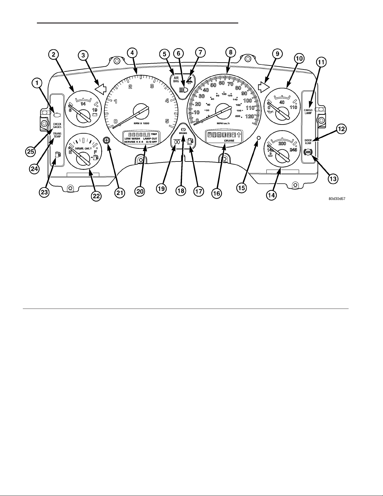
Fig. 4 Gauges & Indicators - Diesel Engine
1 - MALFUNCTION INDICATOR LAMP 14 - ENGINE TEMPERATURE GAUGE
2 - VOLTAGE GAUGE 15 - SECURITY INDICATOR
3 - LEFT TURN INDICATOR 16 - GEAR SELECTOR INDICATOR DISPLAY (INCLUDES
4 - TACHOMETER 17 - WATER-IN-FUEL INDICATOR
5 - AIRBAG INDICATOR 18 - BRAKE INDICATOR
6 - HIGH BEAM INDICATOR 19 - WAIT-TO-START INDICATOR
7 - SEATBELT INDICATOR 20 - ODOMETER/TRIP ODOMETER DISPLAY (INCLUDES
8 - SPEEDOMETER 21 - ODOMETER/TRIP ODOMETER SWITCH BUTTON
9 - RIGHT TURN INDICATOR 22 - FUEL GAUGE
10 - OIL PRESSURE GAUGE 23 - LOW FUEL INDICATOR
11 - CARGO LAMP INDICATOR 24 - TRANSMISSION OVERTEMP INDICATOR
12 - DOOR AJAR INDICATOR 25 - CHECK GAUGES INDICATOR
13 - ABS INDICATOR
The EMIC microprocessor smooths the input data
using algorithms to provide gauge readings that are
accurate, stable and responsive to operating conditions. These algorithms are designed to provide
gauge readings during normal operation that are consistent with customer expectations. However, when
abnormal conditions exist such as high coolant temperature, the algorithm can drive the gauge pointer
to an extreme position and the microprocessor can
sound a chime through the on-board audible tone
generator to provide distinct visual and audible indications of a problem to the vehicle operator. The
instrument cluster circuitry may also produce audible warnings for other electronic modules in the vehicle based upon electronic tone request messages
received over the PCI data bus. Each audible warning is intended to provide the vehicle operator with
an audible alert to supplement a visual indication.
CRUISE & UPSHIFT INDICATORS)
ENGINE HOURS, WASHER FLUID, LAMP OUTAGE,
OVERDRIVE-OFF & SERVICE 4x4 INDICATORS)
The EMIC circuitry operates on battery current
received through a fused B(+) fuse in the Integrated
Power Module (IPM) on a non-switched fused B(+)
circuit, and on battery current received through a
fused ignition switch output (run-start) fuse in the
IPM on a fused ignition switch output (run-start) circuit. This arrangement allows the EMIC to provide
some features regardless of the ignition switch position, while other features will operate only with the
ignition switch in the On or Start positions. The
EMIC circuitry is grounded through a ground circuit
and take out of the instrument panel wire harness
with an eyelet terminal connector that is secured by
a ground screw to a ground location near the center
of the instrument panel structural support.
The EMIC also has a self-diagnostic actuator test
capability, which will test each of the PCI bus message-controlled functions of the cluster by lighting
the appropriate indicators, positioning the gauge nee-
Page 8

8J - 8 INSTRUMENT CLUSTER DR
INSTRUMENT CLUSTER (Continued)
dles at several predetermined calibration points
across the gauge faces, and illuminating all segments
of the odometer/trip odometer and gear selector indicator Vacuum-Fluorescent Display (VFD) units.
(Refer to 8 - ELECTRICAL/INSTRUMENT CLUSTER - DIAGNOSIS AND TESTING). See the owner’s
manual in the vehicle glove box for more information
on the features, use and operation of the EMIC.
GAUGES
All gauges receive battery current through the
EMIC circuitry only when the ignition switch is in
the On or Start positions. With the ignition switch in
the Off position battery current is not supplied to
any gauges, and the EMIC circuitry is programmed
to move all of the gauge needles back to the low end
of their respective scales. Therefore, the gauges do
not accurately indicate any vehicle condition unless
the ignition switch is in the On or Start positions.
All of the EMIC gauges are air core magnetic
units. Two fixed electromagnetic coils are located
within each gauge. These coils are wrapped at right
angles to each other around a movable permanent
magnet. The movable magnet is suspended within
the coils on one end of a pivot shaft, while the gauge
needle is attached to the other end of the shaft. One
of the coils has a fixed current flowing through it to
maintain a constant magnetic field strength. Current
flow through the second coil changes, which causes
changes in its magnetic field strength. The current
flowing through the second coil is changed by the
EMIC circuitry in response to messages received over
the PCI data bus. The gauge needle moves as the
movable permanent magnet aligns itself to the
changing magnetic fields created around it by the
electromagnets.
The gauges are diagnosed using the EMIC self-diagnostic actuator test. (Refer to 8 - ELECTRICAL/
INSTRUMENT CLUSTER - DIAGNOSIS AND
TESTING). Proper testing of the PCI data bus and
the electronic data bus message inputs to the EMIC
that control each gauge require the use of a DRBIIIt
scan tool. Refer to the appropriate diagnostic information. Specific operation details for each gauge may
be found elsewhere in this service information.
VACUUM-FLUORESCENT DISPLAYS
The Vacuum-Fluorescent Display (VFD) units are
soldered to the EMIC electronic circuit board. With
the ignition switch in the Off or Accessory positions,
the odometer display is activated when the driver
door is opened (Rental Car mode) and is deactivated
when the driver door is closed. Otherwise, both display units are active when the ignition switch is in
the On or Start positions, and inactive when the ignition switch is in the Off or Accessory positions.
The illumination intensity of the VFD units is controlled by the EMIC circuitry based upon an input
from the headlamp switch and a dimming level input
received from the headlamp dimmer switch. The
EMIC synchronizes the illumination intensity of
other VFD units with that of the units in the EMIC
by sending electronic dimming level messages to
other electronic modules in the vehicle over the PCI
data bus.
The EMIC VFD units have several display capabilities including odometer, trip odometer, engine hours,
gear selector indication (PRNDL) for models with an
automatic transmission, several warning or reminder
indications, and various diagnostic information when
certain fault conditions exist. An odometer/trip odometer switch on the EMIC circuit board is used to control some of the display modes. This switch is
actuated manually by depressing the odometer/trip
odometer switch button that extends through the
lower edge of the cluster lens, just left of the tachometer. Actuating this switch momentarily with the
ignition switch in the On position will toggle the
VFD between the odometer and trip odometer modes.
Depressing the switch button for about two seconds
while the VFD is in the trip odometer mode will
reset the trip odometer value to zero. While in the
odometer mode with the ignition switch in the On
position and the engine not running, depressing this
switch for about six seconds will display the engine
hours information. Holding this switch depressed
while turning the ignition switch from the Off position to the On position will initiate the EMIC self-diagnostic actuator test. Refer to the appropriate
diagnostic information for additional details on this
VFD function. The EMIC microprocessor remembers
which display mode is active when the ignition
switch is turned to the Off position, and returns the
VFD display to that mode when the ignition switch is
turned On again.
The VFD units are diagnosed using the EMIC selfdiagnostic actuator test. (Refer to 8 - ELECTRICAL/
INSTRUMENT CLUSTER - DIAGNOSIS AND
TESTING). Proper testing of the PCI data bus and
the electronic data bus message inputs to the EMIC
that control some of the VFD functions requires the
use of a DRBIIIt scan tool. Refer to the appropriate
diagnostic information. Specific operation details for
the odometer, the trip odometer, the gear selector
indicator and the various warning and reminder indicator functions of the VFD may be found elsewhere
in this service information.
INDICATORS
Indicators are located in various positions within
the EMIC and are all connected to the EMIC electronic circuit board. The cargo lamp indicator, door
Page 9

DR INSTRUMENT CLUSTER 8J - 9
INSTRUMENT CLUSTER (Continued)
ajar indicator, high beam indicator, and turn signal
indicators operate based upon hard wired inputs to
the EMIC. The brake indicator is controlled by PCI
data bus messages from the Controller Antilock
Brake (CAB) as well as by hard wired park brake
switch inputs to the EMIC. The seatbelt indicator is
controlled by the EMIC programming, PCI data bus
messages from the Airbag Control Module (ACM),
and a hard wired seat belt switch input to the EMIC.
The Malfunction Indicator Lamp (MIL) is normally
controlled by PCI data bus messages from the Powertrain Control Module (PCM); however, if the EMIC
loses PCI data bus communication, the EMIC circuitry will automatically turn the MIL on until PCI
data bus communication is restored. The EMIC uses
PCI data bus messages from the Front Control Module (FCM), the PCM, the diesel engine only Engine
Control Module (ECM), the ACM, the CAB, and the
Sentry Key Immobilizer Module (SKIM) to control all
of the remaining indicators.
The various EMIC indicators are controlled by different strategies; some receive fused ignition switch
output from the EMIC circuitry and have a switched
ground, while others are grounded through the EMIC
circuitry and have a switched battery feed. However,
all indicators are completely controlled by the EMIC
microprocessor based upon various hard wired and
electronic message inputs. All indicators are illuminated at a fixed intensity, which is not affected by
the selected illumination intensity of the EMIC general illumination lamps.
In addition, certain indicators in this instrument
cluster are automatically configured or self-configured. This feature allows the configurable indicators
to be enabled by the EMIC circuitry for compatibility
with certain optional equipment. The EMIC defaults
for the ABS indicator and airbag indicator are
enabled, and these configuration settings must be
programmatically disabled in the EMIC using a
DRBIIIt scan tool for vehicles that do not have this
equipment. The automatically configured or self-configured indicators remain latent in each EMIC at all
times and will be active only when the EMIC
receives the appropriate PCI message inputs for that
optional system or equipment.
The hard wired indicator inputs may be diagnosed
using conventional diagnostic methods. However, the
EMIC circuitry and PCI bus message controlled indicators are diagnosed using the EMIC self-diagnostic
actuator test. (Refer to 8 - ELECTRICAL/INSTRUMENT CLUSTER - DIAGNOSIS AND TESTING).
Proper testing of the PCI data bus and the electronic
message inputs to the EMIC that control an indicator
requires the use of a DRBIIIt scan tool. Refer to the
appropriate diagnostic information. Specific details of
the operation for each indicator may be found elsewhere in this service information.
CLUSTER ILLUMINATION
The EMIC has several illumination lamps that are
illuminated when the exterior lighting is turned on
with the headlamp switch. The illumination intensity
of these lamps is adjusted when the interior lighting
thumbwheel on the headlamp switch is rotated (down
to dim, up to brighten) to one of six available minor
detent positions. The EMIC monitors a resistor multiplexed input from the headlamp switch on a dimmer input circuit. In response to that input, the
EMIC electronic circuitry converts a 12-volt input it
receives from a fuse in the Integrated Power Module
(IPM) on a hard wired panel lamps dimmer switch
signal circuit into a 12-volt Pulse Width Modulated
(PWM) output. The EMIC uses this PWM output to
power the cluster illumination lamps and the VFD
units on the EMIC circuit board, then provides a synchronized PWM output on the various hard wired
fused panel lamps dimmer switch signal circuits to
control and synchronize the illumination intensity of
other incandescent illumination lamps in the vehicle.
The cluster illumination lamps are grounded at all
times.
The EMIC also sends electronic dimming level
messages over the PCI data bus to other electronic
modules in the vehicle to control and synchronize the
illumination intensity of their VFD units to that of
the EMIC VFD units. In addition, the thumbwheel
on the headlamp switch has a Parade Mode position
to provide a parade mode. The EMIC monitors the
request for this mode from the headlamp switch,
then sends an electronic dimming level message over
the PCI data bus to illuminate all VFD units in the
vehicle at full (daytime) intensity for easier visibility
when driving in daylight with the exterior lighting
turned on.
The hard wired headlamp switch and EMIC panel
lamps dimmer inputs and outputs may be diagnosed
using conventional diagnostic methods. However,
proper testing of the PWM output of the EMIC and
the electronic dimming level messages sent by the
EMIC over the PCI data bus requires the use of a
DRBIIIt scan tool. Refer to the appropriate diagnostic information.
INPUT AND OUTPUT CIRCUITS
HARD WIRED INPUTS
The hard wired inputs to the EMIC include the following:
• Brake Lamp Switch Output
• Driver Cylinder Lock Switch Sense
• Driver Door Ajar Switch Sense
Page 10

8J - 10 INSTRUMENT CLUSTER DR
INSTRUMENT CLUSTER (Continued)
• Driver Door Lock Switch MUX - with
Power Locks
• Fused B(+) - Ignition-Off Draw
• Fused B(+) - Power Lock Feed - with Power
Locks
• Fused Ignition Switch Output (Accessory-
Run)
• Fused Ignition Switch Output (Off-Run-
Start)
• Fused Ignition Switch Output (Run-Start)
• Headlamp Dimmer Switch MUX
• Headlamp Switch MUX
• Horn Relay Control
• Key-In Ignition Switch Sense
• Left Rear Door Ajar Switch Sense
• Panel Lamps Dimmer Switch Signal
• Park Brake Switch Sense
• Passenger Door Ajar Switch Sense
• Passenger Door Lock Switch MUX - with
Power Locks
• Radio Control MUX
• Right Rear Door Ajar Switch Sense
• RKE Supply - with RKE
• Seat Belt Switch Sense
• Transmission Range Sensor MUX - with
Auto Trans
• Turn/Hazard Switch MUX
• Washer/Beam Select Switch MUX
• Wiper Switch MUX
Refer to the appropriate wiring information for
additional details.
• Radio Illumination Driver
• Right Door Lock Driver - with Power Locks
• Right Door Unlock Driver - with Power
Locks
• Transfer Case Switch Illumination Driver -
with Four-Wheel Drive
Refer to the appropriate wiring information for
additional details.
GROUNDS
The EMIC receives and supplies a ground path to
several switches and sensors through the following
hard wired circuits:
• Ground - Illumination (2 Circuits)
• Ground - Power Lock - with Power Locks
• Ground - Signal
• Headlamp Switch Return
• Multi-Function Switch Return
• Transmission Range Sensor Return - with
Auto Trans
Refer to the appropriate wiring information for
additional details.
COMMUNICATION
The EMIC has provisions for the following communication circuits:
• PCI Data Bus
• RKE Program Serial Data - with RKE
• RKE Transmit Serial Data - with RKE
Refer to the appropriate wiring information for
additional details.
HARD WIRED OUTPUTS
The hard wired outputs of the EMIC include the
following:
• Accessory Switch Bank Illumination Driver
• BTSI Driver - with Auto Trans
• Cargo Lamp Driver
• Dome/Overhead Lamp Driver
• Driver Door Unlock Driver - with Power
Locks
• Headlamp Switch Illumination Driver
• Heated Seat Switch Indicator Driver - with
Heated Seats
• Heater-A/C Control Illumination Driver
• Left Door Lock Driver - with Power Locks
• Left Rear Door Unlock Driver - with Power
Locks
• Map/Glove Box Lamp Driver
DIAGNOSIS AND TESTING - INSTRUMENT
CLUSTER
If all of the instrument cluster gauges and/or indicators are inoperative, refer to PRELIMINARY
DIAGNOSIS. If an individual gauge or Programmable Communications Interface (PCI) data bus message-controlled indicator is inoperative, refer to
ACTUATOR TEST. If an individual hard wired indicator is inoperative, refer to the diagnosis and testing
information for that specific indicator.
Refer to the appropriate wiring information. The
wiring information includes wiring diagrams, proper
wire and connector repair procedures, details of wire
harness routing and retention, connector pin-out
information and location views for the various wire
harness connectors, splices and grounds.
Page 11

DR INSTRUMENT CLUSTER 8J - 11
INSTRUMENT CLUSTER (Continued)
CAUTION: Instrument clusters used in this model
automatically configure themselves for compatibility with the features and optional equipment in the
vehicle in which they are initially installed. The
instrument cluster is programmed to do this by
embedding the Vehicle Identification Number (VIN)
and other information critical to proper cluster
operation into electronic memory. This embedded
information is learned through electronic messages
received from other electronic modules in the vehicle over the Programmable Communications Interface (PCI) data bus, and through certain hard wired
inputs received when the cluster is connected to
the vehicle electrically. Once configured, the instrument cluster memory may be irreparably damaged
and certain irreversible configuration errors may
occur if the cluster is connected electrically to
another vehicle; or, if an electronic module from
another vehicle is connected that provides data to
the instrument cluster (including odometer values)
that conflicts with that which was previously
learned and stored. Therefore, the practice of
exchanging (swapping) instrument clusters and
other electronic modules in this vehicle with those
removed from another vehicle must always be
avoided. Failure to observe this caution may result
in instrument cluster damage, which is not reimbursable under the terms of the product warranty.
Service replacement instrument clusters are provided with the correct VIN, and the certified odometer and engine hours values embedded into cluster
memory, but will otherwise be automatically configured for compatibility with the features and optional
equipment in the vehicle in which they are initially
installed.
NOTE: Certain indicators in this instrument cluster
are automatically configured. This feature allows
those indicators to be activated or deactivated for
compatibility with certain optional equipment. If the
problem being diagnosed involves improper illumination of the cruise indicator, the electronic throttle
control indicator, the overdrive-off indicator, the
service four-wheel drive indicator, the transmission
overtemp indicator, the upshift indicator, the security indicator or the gear selector indicator, disconnect and isolate the battery negative cable. After
about five minutes, reconnect the battery negative
cable and turn the ignition switch to the On position. The instrument cluster should automatically
relearn the equipment in the vehicle and properly
configure the configurable indicators accordingly.
PRELIMINARY DIAGNOSIS
WARNING: ON VEHICLES EQUIPPED WITH AIRBAGS, DISABLE THE SUPPLEMENTAL RESTRAINT
SYSTEM BEFORE ATTEMPTING ANY STEERING
WHEEL, STEERING COLUMN, DRIVER AIRBAG,
PASSENGER AIRBAG, SEAT BELT TENSIONER,
SIDE CURTAIN AIRBAG, OR INSTRUMENT PANEL
COMPONENT DIAGNOSIS OR SERVICE. DISCONNECT AND ISOLATE THE BATTERY NEGATIVE
(GROUND) CABLE, THEN WAIT TWO MINUTES FOR
THE SYSTEM CAPACITOR TO DISCHARGE BEFORE
PERFORMING FURTHER DIAGNOSIS OR SERVICE.
THIS IS THE ONLY SURE WAY TO DISABLE THE
SUPPLEMENTAL RESTRAINT SYSTEM. FAILURE TO
TAKE THE PROPER PRECAUTIONS COULD
RESULT IN ACCIDENTAL AIRBAG DEPLOYMENT
AND POSSIBLE PERSONAL INJURY.
(1) Check the fused B(+) fuse (Fuse 28 - 10
ampere) in the Integrated Power Module (IPM). If
OK, go to Step 2. If not OK, repair the shorted circuit
or component as required and replace the faulty fuse.
(2) Check for battery voltage at the fused B(+) fuse
(Fuse 28 - 10 ampere) in the IPM. If OK, go to Step
3. If not OK, repair the open fused B(+) circuit
between the IPM and the battery as required.
(3) Disconnect and isolate the battery negative
cable. Remove the instrument cluster. Reconnect the
battery negative cable. Check for battery voltage at
the fused B(+) circuit cavity of the instrument panel
wire harness connector (Connector C1) for the instrument cluster. If OK, go to Step 4. If not OK, repair
the open fused B(+) circuit between the instrument
cluster and the IPM as required.
(4) Check for continuity between the signal ground
circuit cavity of the instrument panel wire harness
connector (Connector C1) for the instrument cluster
and a good ground. There should be continuity. If
OK, refer to ACTUATOR TEST. If not OK, repair the
open ground circuit to ground (G202) as required.
Page 12

8J - 12 INSTRUMENT CLUSTER DR
INSTRUMENT CLUSTER (Continued)
ACTUATOR TEST
WARNING: ON VEHICLES EQUIPPED WITH AIRBAGS, DISABLE THE SUPPLEMENTAL RESTRAINT
SYSTEM BEFORE ATTEMPTING ANY STEERING
WHEEL, STEERING COLUMN, DRIVER AIRBAG,
PASSENGER AIRBAG, SEAT BELT TENSIONER,
SIDE CURTAIN AIRBAG, OR INSTRUMENT PANEL
COMPONENT DIAGNOSIS OR SERVICE. DISCONNECT AND ISOLATE THE BATTERY NEGATIVE
(GROUND) CABLE, THEN WAIT TWO MINUTES FOR
THE SYSTEM CAPACITOR TO DISCHARGE BEFORE
PERFORMING FURTHER DIAGNOSIS OR SERVICE.
THIS IS THE ONLY SURE WAY TO DISABLE THE
SUPPLEMENTAL RESTRAINT SYSTEM. FAILURE TO
TAKE THE PROPER PRECAUTIONS COULD
RESULT IN ACCIDENTAL AIRBAG DEPLOYMENT
AND POSSIBLE PERSONAL INJURY.
The instrument cluster actuator test will put the
instrument cluster into its self-diagnostic mode. In
this mode the instrument cluster can perform a selfdiagnostic test that will confirm that the instrument
cluster circuitry, the gauges, and the indicators are
capable of operating as designed. During the actuator
test the instrument cluster circuitry will position
each of the gauge needles at various calibration
points, illuminate all of the segments in the Vacuum
Fluorescent Display (VFD) units, turn all of the indicators on and off again, display any Diagnostic Trouble Code (DTC) information, and display the number
of ignition key cycles that have occurred since the
DTC was detected. It is suggested that a note pad
and pencil be used to write down any fault information that is displayed during the test for reference.
Successful completion of the actuator test will confirm that the instrument cluster is operational. However, there may still be a problem with the PCI data
bus, the Powertrain Control Module (PCM), the
Engine Control Module (ECM), the Front Control
Module (FCM), the Transmission Control Module
(TCM), the Transfer Case Control Module (TCCM),
the Airbag Control Module (ACM), the Controller
Anti-lock Brake (CAB), or the inputs to one of these
electronic control modules. Use a DRBIIIt scan tool
to diagnose these components. Refer to the appropriate diagnostic information.
(1) Begin the test with the ignition switch in the
Off position.
(2) Depress the odometer/trip odometer switch but-
ton.
(3) While still holding the odometer/trip odometer
switch button depressed, turn the ignition switch to
the On position, but do not start the engine.
(4) Release the odometer/trip odometer switch button.
(5) The instrument cluster will simultaneously
illuminate all of the operational segments in both
VFD units, perform a bulb check of each operational
LED indicator. The VFD segments and LED indicators remain illuminated as each gauge needle is
swept to several calibration points and back. If a
VFD segment or an LED indicator fails to illuminate,
or if a gauge needle fails to sweep through the calibration points and back during this test, the instrument cluster must be replaced. Following these tests,
the actuator test will proceed as described in Step 6.
(6) The text “C Code” is displayed in the odometer
VFD for about three seconds. If there is no stored
fault information, the display will show two pairs of
zeroes in the format “00” “00”, which indicate that
the display of fault information is done. If there is
stored fault information, two sets of two-digit alpha
and alpha-numeric fault codes will appear in the
odometer display for a three second interval. The
first pair of digits represents a Diagnostic Trouble
Code (DTC), or fault code for the instrument cluster.
The second pair of digits is a counter for the number
of ignition key cycles that have occurred since the
displayed DTC was set. The instrument cluster will
continue to display additional sets of two pairs of digits at three second intervals until all of the stored
codes have been displayed, which is again signaled
by a code of “00” “00”. Refer to the Instrument Cluster Failure Message table for a description of each
fault code that the instrument cluster displays. If an
instrument cluster fault is displayed, use a DRBIIIt
scan tool to diagnose the problem. Refer to the appropriate diagnostic information.
INSTRUMENT CLUSTER FAILURE MESSAGE
Fault Code Description Correction
01 Airbag warning indicator output circuit shorted. Refer to the appropriate diagnostic information.
02 Airbag warning indicator output circuit open. Refer to the appropriate diagnostic information.
03 ABS indicator output circuit shorted. Refer to the appropriate diagnostic information.
04 ABS indicator output circuit open. Refer to the appropriate diagnostic information.
05 MIL indicator output circuit shorted. Refer to the appropriate diagnostic information.
06 MIL indicator output circuit open. Refer to the appropriate diagnostic information.
Page 13

DR INSTRUMENT CLUSTER 8J - 13
INSTRUMENT CLUSTER (Continued)
INSTRUMENT CLUSTER FAILURE MESSAGE
Fault Code Description Correction
07 Wait to start indicator circuit shorted. Refer to the appropriate diagnostic information.
08 Wait to start indicator circuit open. Refer to the appropriate diagnostic information.
0B BTSI output circuit shorted or open. Refer to the appropriate diagnostic information.
22 Headlamp switch input circuit shorted. Refer to the appropriate diagnostic information.
23 Headlamp switch input circuit open. Refer to the appropriate diagnostic information.
24 Turn hazard switch input circuit shorted. Refer to the appropriate diagnostic information.
25 Turn hazard swiitch inpot circuit open. Refer to the appropriate diagnostic information.
27 Courtesy/dome output circuit shorted or open. Refer to the appropriate diagnostic information.
28 Glovebox/map lamp output circuit shorted or
open.
29 Cargo lamp output circuit shorted or open. Refer to the appropriate diagnostic information.
40 Wiper switch input circuit shorted. Refer to the appropriate diagnostic information.
41 Wiper switch input circuit open. Refer to the appropriate diagnostic information.
42 Wash/beam input circuit shorted. Refer to the appropriate diagnostic information.
60 Passenger door lock switch input circuit shorted. Refer to the appropriate diagnostic information.
61 Passenger door lock switch input circuit open. Refer to the appropriate diagnostic information.
62 Passenger door lock switch input circuit stuck. Refer to the appropriate diagnostic information.
63 Driver door lock switch input circuit shorted. Refer to the appropriate diagnostic information.
64 Driver door lock switch input circuit open. Refer to the appropriate diagnostic information.
65 Driver door lock switch input circuit stuck. Refer to the appropriate diagnostic information.
66 All door lock output circuit shorted to ground or
voltage.
67 All door unlock output circuit shorted to ground
or voltage.
68 Driver door unlock output circuit shorted to
ground or voltage.
6C Driver cylinder lock switch input circuit shorted. Refer to the appropriate diagnostic information.
6E Driver cylinder lock switch input circuit stuck. Refer to the appropriate diagnostic information.
80 Incorrect odometer value found. Refer to the appropriate diagnostic information.
81 Remote radio switch input circuit high. Refer to the appropriate diagnostic information.
82 Remote radio switch stuck. Refer to the appropriate diagnostic information.
A0 Internal module FLASH memory checksum
failure.
A1 Internal module bootloader failure. Refer to the appropriate diagnostic information.
A3 Battery voltage open. Refer to the appropriate diagnostic information.
A5 TCCM messages not received. Refer to the appropriate diagnostic information.
A7 VIN checksum error. Refer to the appropriate diagnostic information.
A8 VIN previously stored. Refer to the appropriate diagnostic information.
A9 PCI bus internal failure. Refer to the appropriate diagnostic information.
AA PCM messages not received. Refer to the appropriate diagnostic information.
AB TCM messages not received. Refer to the appropriate diagnostic information.
AC ABS messages not received. Refer to the appropriate diagnostic information.
Refer to the appropriate diagnostic information.
Refer to the appropriate diagnostic information.
Refer to the appropriate diagnostic information.
Refer to the appropriate diagnostic information.
Refer to the appropriate diagnostic information.
Page 14
8J - 14 INSTRUMENT CLUSTER DR
INSTRUMENT CLUSTER (Continued)
INSTRUMENT CLUSTER FAILURE MESSAGE
Fault Code Description Correction
AD FCM messages not received. Refer to the appropriate diagnostic information.
AE ACM messages not received. Refer to the appropriate diagnostic information.
AF SKIM messages not received. Refer to the appropriate diagnostic information.
B0 RKE fob batteries low. Refer to the appropriate diagnostic information.
B1 RKE module communication link. Refer to the appropriate diagnostic information.
00 Done All Diagnostic Trouble Codes (DTC) have been
displayed.
(7) The actuator test is now completed. The instrument cluster will automatically exit the self-diagnostic mode and return to normal operation at the
completion of the test, if the ignition switch is turned
to the Off position during the test, or if a vehicle
speed message indicating that the vehicle is moving
is received from the PCM over the PCI data bus during the test.
(8)
Go back to Step 1 to repeat the test, if necessary.
REMOVAL
WARNING: ON VEHICLES EQUIPPED WITH AIRBAGS, DISABLE THE SUPPLEMENTAL RESTRAINT
SYSTEM BEFORE ATTEMPTING ANY STEERING
WHEEL, STEERING COLUMN, DRIVER AIRBAG,
PASSENGER AIRBAG, SEAT BELT TENSIONER,
SIDE CURTAIN AIRBAG, OR INSTRUMENT PANEL
COMPONENT DIAGNOSIS OR SERVICE. DISCONNECT AND ISOLATE THE BATTERY NEGATIVE
(GROUND) CABLE, THEN WAIT TWO MINUTES FOR
THE SYSTEM CAPACITOR TO DISCHARGE BEFORE
PERFORMING FURTHER DIAGNOSIS OR SERVICE.
THIS IS THE ONLY SURE WAY TO DISABLE THE
SUPPLEMENTAL RESTRAINT SYSTEM. FAILURE TO
TAKE THE PROPER PRECAUTIONS COULD
RESULT IN ACCIDENTAL AIRBAG DEPLOYMENT
AND POSSIBLE PERSONAL INJURY.
(1) Disconnect and isolate the battery negative
cable.
(2) Remove the cluster bezel from the instrument
panel. (Refer to 23 - BODY/INSTRUMENT PANEL/
CLUSTER BEZEL - REMOVAL).
(3) Remove the four screws that secure the instrument cluster to the instrument panel structural support (Fig. 5).
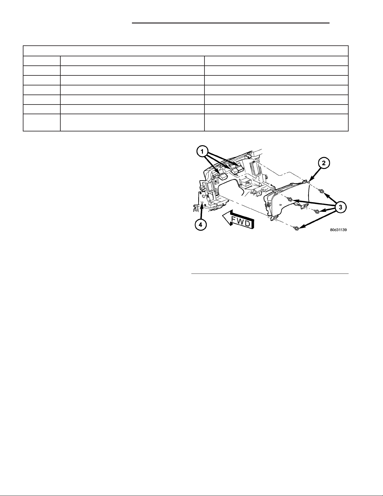
Fig. 5 Instrument Cluster Remove/Install
1 - WIRE HARNESS CONNECTOR (3)
2 - INSTRUMENT CLUSTER
3 - SCREW (4)
4 - INSTRUMENT PANEL STRUCTURAL SUPPORT
(4) Pull the instrument cluster rearward far
enough to access and disconnect the instrument
panel wire harness connectors for the cluster from
the connector receptacles on the back of the cluster
housing.
(5) Remove the instrument cluster from the instrument panel.
DISASSEMBLY
Some of the components for the instrument cluster
used in this vehicle are serviced individually. The
serviced components include the incandescent instrument cluster illumination lamp bulbs (including the
integral bulb holders), and the cluster lens, hood and
mask unit. Following are the procedures for disassembling these components from the instrument cluster unit.
Page 15

DR INSTRUMENT CLUSTER 8J - 15
INSTRUMENT CLUSTER (Continued)
WARNING: ON VEHICLES EQUIPPED WITH AIRBAGS, DISABLE THE SUPPLEMENTAL RESTRAINT
SYSTEM BEFORE ATTEMPTING ANY STEERING
WHEEL, STEERING COLUMN, DRIVER AIRBAG,
PASSENGER AIRBAG, SEAT BELT TENSIONER,
SIDE CURTAIN AIRBAG, OR INSTRUMENT PANEL
COMPONENT DIAGNOSIS OR SERVICE. DISCONNECT AND ISOLATE THE BATTERY NEGATIVE
(GROUND) CABLE, THEN WAIT TWO MINUTES FOR
THE SYSTEM CAPACITOR TO DISCHARGE BEFORE
PERFORMING FURTHER DIAGNOSIS OR SERVICE.
THIS IS THE ONLY SURE WAY TO DISABLE THE
SUPPLEMENTAL RESTRAINT SYSTEM. FAILURE TO
TAKE THE PROPER PRECAUTIONS COULD
RESULT IN ACCIDENTAL AIRBAG DEPLOYMENT
AND POSSIBLE PERSONAL INJURY.
CLUSTER BULB
This procedure applies to each of the incandescent
cluster illumination lamp bulb and bulb holder units.
If the vehicle is equipped with the optional Remote
Keyless Entry (RKE) system, the RKE receiver module must be removed from the instrument cluster
rear cover to access the lower center cluster illumination lamp, which is located on the circuit board
directly behind the RKE module. (Refer to 8 - ELECTRICAL/POWER LOCKS/REMOTE KEYLESS
ENTRY MODULE - REMOVAL).
(1) Disconnect and isolate the battery negative
cable.
(2) Remove the instrument cluster from the instrument panel. (Refer to 8 - ELECTRICAL/INSTRUMENT CLUSTER - REMOVAL).
(3) Turn the bulb holder counterclockwise about
sixty degrees on the cluster electronic circuit board
(Fig. 6).
(4) Pull the bulb and bulb holder unit straight
back to remove it from the bulb mounting hole in the
cluster electronic circuit board.
CLUSTER LENS, HOOD, AND MASK
(1) Disconnect and isolate the battery negative
cable.
(2) Remove the instrument cluster from the instrument panel. (Refer to 8 - ELECTRICAL/INSTRUMENT CLUSTER - REMOVAL).
(3) From the back of the instrument cluster,
remove the eight screws around the outer perimeter
of the rear cover that secure the lens, hood, and
mask unit to the cluster housing (Fig. 7).
Fig. 7 Instrument Cluster Components
1 - SCREW (9)
2 - REAR COVER
3 - CLUSTER HOUSING
4 - LENS, HOOD & MASK
(4) Remove the lens, hood, and mask unit from the
face of the instrument cluster.
Fig. 6 Cluster Bulb Remove/Install
1 - INSTRUMENT CLUSTER
2 - BULB & HOLDER (11)
ASSEMBLY
Some of the components for the instrument cluster
used in this vehicle are serviced individually. The
serviced components include the incandescent instrument cluster illumination lamp bulbs (including the
integral bulb holders), and the cluster lens, hood and
mask unit. Following are the procedures for assembling these components to the instrument cluster
unit.
Page 16

8J - 16 INSTRUMENT CLUSTER DR
INSTRUMENT CLUSTER (Continued)
WARNING: ON VEHICLES EQUIPPED WITH AIRBAGS, DISABLE THE SUPPLEMENTAL RESTRAINT
SYSTEM BEFORE ATTEMPTING ANY STEERING
WHEEL, STEERING COLUMN, DRIVER AIRBAG,
PASSENGER AIRBAG, SEAT BELT TENSIONER,
SIDE CURTAIN AIRBAG, OR INSTRUMENT PANEL
COMPONENT DIAGNOSIS OR SERVICE. DISCONNECT AND ISOLATE THE BATTERY NEGATIVE
(GROUND) CABLE, THEN WAIT TWO MINUTES FOR
THE SYSTEM CAPACITOR TO DISCHARGE BEFORE
PERFORMING FURTHER DIAGNOSIS OR SERVICE.
THIS IS THE ONLY SURE WAY TO DISABLE THE
SUPPLEMENTAL RESTRAINT SYSTEM. FAILURE TO
TAKE THE PROPER PRECAUTIONS COULD
RESULT IN ACCIDENTAL AIRBAG DEPLOYMENT
AND POSSIBLE PERSONAL INJURY.
CLUSTER BULB
This procedure applies to each of the incandescent
cluster illumination lamp bulb and bulb holder units.
If the vehicle is equipped with the optional Remote
Keyless Entry (RKE) system, and the RKE receiver
module was removed from the instrument cluster
rear cover to access the lower center cluster illumination lamp, reinstall the RKE module after the bulb
is replaced on the circuit board. (Refer to 8 - ELECTRICAL/POWER LOCKS/REMOTE KEYLESS
ENTRY MODULE - INSTALLATION).
CAUTION: Always use the correct bulb size and
type for replacement. An incorrect bulb size or type
may overheat and cause damage to the instrument
cluster, the electronic circuit board and/or the
gauges.
(1) Insert the bulb and bulb holder unit straight
into the correct bulb mounting hole in the cluster
electronic circuit board (Fig. 6).
(2) With the bulb holder fully seated against the
cluster electronic circuit board, turn the bulb holder
clockwise about sixty degrees to lock it into place.
(3) Reinstall the instrument cluster onto the
instrument panel. (Refer to 8 - ELECTRICAL/INSTRUMENT CLUSTER - INSTALLATION).
(4) Reconnect the battery negative cable.
CLUSTER LENS, HOOD, AND MASK
(1) Position the cluster lens, hood, and mask unit
over the face of the instrument cluster (Fig. 7). Be
certain that the odometer/trip odometer switch button is inserted through the proper clearance holes in
the mask and the lens.
(2) From the back of the instrument cluster, install
and tighten the eight screws around the outer perimeter of the rear cover that secure the lens, hood, and
mask unit to the cluster housing. Tighten the screws
to 1 N·m (10 in. lbs.).
(3) Reinstall the instrument cluster onto the
instrument panel. (Refer to 8 - ELECTRICAL/INSTRUMENT CLUSTER - INSTALLATION).
(4) Reconnect the battery negative cable.
INSTALLATION
WARNING: ON VEHICLES EQUIPPED WITH AIRBAGS, DISABLE THE SUPPLEMENTAL RESTRAINT
SYSTEM BEFORE ATTEMPTING ANY STEERING
WHEEL, STEERING COLUMN, DRIVER AIRBAG,
PASSENGER AIRBAG, SEAT BELT TENSIONER,
SIDE CURTAIN AIRBAG, OR INSTRUMENT PANEL
COMPONENT DIAGNOSIS OR SERVICE. DISCONNECT AND ISOLATE THE BATTERY NEGATIVE
(GROUND) CABLE, THEN WAIT TWO MINUTES FOR
THE SYSTEM CAPACITOR TO DISCHARGE BEFORE
PERFORMING FURTHER DIAGNOSIS OR SERVICE.
THIS IS THE ONLY SURE WAY TO DISABLE THE
SUPPLEMENTAL RESTRAINT SYSTEM. FAILURE TO
TAKE THE PROPER PRECAUTIONS COULD
RESULT IN ACCIDENTAL AIRBAG DEPLOYMENT
AND POSSIBLE PERSONAL INJURY.
(1) Position the instrument cluster to the instrument panel.
(2) Reconnect the instrument panel wire harness
connectors for the cluster to the connector receptacles
on the back of the cluster housing.
(3) Position the instrument cluster into the instrument panel.
(4) Install and tighten the four screws that secure
the instrument cluster to the instrument panel structural support (Fig. 5). Tighten the screws to 4 N·m
(31 in. lbs.).
(5) Reinstall the cluster bezel onto the instrument
panel. (Refer to 23 - BODY/INSTRUMENT PANEL/
CLUSTER BEZEL - INSTALLATION).
(6) Reconnect the battery negative cable.
Page 17

DR INSTRUMENT CLUSTER 8J - 17
INSTRUMENT CLUSTER (Continued)
NOTE: Certain indicators in this instrument cluster
are automatically configured. This feature allows
those indicators to be activated or deactivated for
compatibility with certain optional equipment. If the
problem being diagnosed involves improper illumination of the cruise indicator, the electronic throttle
control indicator, the overdrive-off indicator, the
service four-wheel drive indicator, the transmission
overtemp indicator, the upshift indicator, the security indicator or the gear selector indicator, disconnect and isolate the battery negative cable. After
about five minutes, reconnect the battery negative
cable and turn the ignition switch to the On position. The instrument cluster should automatically
relearn the equipment in the vehicle and properly
configure the configurable indicators accordingly.
ABS INDICATOR
DESCRIPTION
An Antilock Brake System (ABS) indicator is standard equipment on all instrument clusters. However,
the instrument cluster can be programmed to disable
this indicator on vehicles that are not equipped with
the ABS or Rear Wheel Anti-Lock (RWAL) brake systems, which are not available in some markets. On
vehicles equipped with a gasoline engine, the ABS
indicator is located near the lower edge of the instrument cluster, between the tachometer and the speedometer. On vehicles equipped with a diesel engine,
the ABS indicator is located on the right side of the
instrument cluster, to the right of the engine temperature gauge. The ABS indicator consists of a stencillike cutout of the International Control and Display
Symbol icon for “Failure of Anti-lock Braking System” in the opaque layer of the instrument cluster
overlay. The dark outer layer of the overlay prevents
the indicator from being clearly visible when it is not
illuminated. An amber Light Emitting Diode (LED)
behind the cutout in the opaque layer of the overlay
causes the icon to appear in amber through the
translucent outer layer of the overlay when the indicator is illuminated from behind by the LED, which
is soldered onto the instrument cluster electronic circuit board. The ABS indicator is serviced as a unit
with the instrument cluster.
OPERATION
The ABS indicator gives an indication to the vehicle operator when the ABS system is faulty or inoperative. This indicator is controlled by a transistor on
the instrument cluster circuit board based upon cluster programming and electronic messages received by
the cluster from the Controller Antilock Brake (CAB)
over the Programmable Communications Interface
(PCI) data bus. The ABS indicator Light Emitting
Diode (LED) is completely controlled by the instrument cluster logic circuit, and that logic will only
allow this indicator to operate when the instrument
cluster receives a battery current input on the fused
ignition switch output (run-start) circuit. Therefore,
the LED will always be off when the ignition switch
is in any position except On or Start. The LED only
illuminates when it is provided a path to ground by
the instrument cluster transistor. The instrument
cluster will turn on the ABS indicator for the following reasons:
• Bulb Test - Each time the ignition switch is
turned to the On position the ABS indicator is illuminated by the cluster for about two seconds as a
bulb test.
• ABS Lamp-On Message - Each time the clus-
ter receives a lamp-on message from the CAB, the
ABS indicator will be illuminated. The indicator
remains illuminated until the cluster receives a
lamp-off message from the CAB, or until the ignition
switch is turned to the Off position, whichever occurs
first.
• Communication Error - If the cluster receives
no lamp-on or lamp-off messages from the CAB for
three consecutive seconds, the ABS indicator is illuminated. The indicator remains illuminated until the
cluster receives a valid message from the CAB, or
until the ignition switch is turned to the Off position,
whichever occurs first.
• Actuator Test - Each time the instrument clus-
ter is put through the actuator test, the ABS indicator will be turned on, then off again during the bulb
check portion of the test to confirm the functionality
of the LED and the cluster control circuitry.
• ABS Diagnostic Test - The ABS indicator is
blinked on and off by lamp-on and lamp-off messages
from the CAB during the performance of the ABS
diagnostic tests.
The CAB continually monitors the ABS circuits
and sensors to decide whether the system is in good
operating condition. The CAB then sends the proper
lamp-on or lamp-off messages to the instrument cluster. If the CAB sends a lamp-on message after the
bulb test, it indicates that the CAB has detected a
system malfunction and/or that the ABS system has
become inoperative. The CAB will store a Diagnostic
Trouble Code (DTC) for any malfunction it detects.
Each time the ABS indicator fails to light due to an
open or short in the cluster ABS indicator circuit, the
cluster sends a message notifying the CAB of the
condition, then the instrument cluster and the CAB
will each store a DTC. For proper diagnosis of the
antilock brake system, the CAB, the PCI data bus, or
the electronic message inputs to the instrument clus-
Page 18

8J - 18 INSTRUMENT CLUSTER DR
ABS INDICATOR (Continued)
ter that control the ABS indicator, a DRBIIIt scan
tool is required. Refer to the appropriate diagnostic
information.
AIRBAG INDICATOR
DESCRIPTION
An airbag indicator is standard equipment on all
instrument clusters. However, the instrument cluster
can be programmed to disable this indicator on vehicles that are not equipped with the airbag system,
which is not available in some markets. The airbag
indicator is located near the upper edge of the instrument cluster, between the tachometer and the speedometer. The airbag indicator consists of a stencil-like
cutout of the words “AIR BAG” in the opaque layer of
the instrument cluster overlay. The dark outer layer
of the overlay prevents the indicator from being
clearly visible when it is not illuminated. A red Light
Emitting Diode (LED) behind the cutout in the
opaque layer of the overlay causes the “AIR BAG”
text to appear in red through the translucent outer
layer of the overlay when the indicator is illuminated
from behind by the LED, which is soldered onto the
instrument cluster electronic circuit board. The airbag indicator is serviced as a unit with the instrument cluster.
OPERATION
The airbag indicator gives an indication to the
vehicle operator when the airbag system is faulty or
inoperative. The airbag indicator is controlled by a
transistor on the instrument cluster circuit board
based upon cluster programming and electronic messages received by the cluster from the Airbag Control
Module (ACM) over the Programmable Communications Interface (PCI) data bus. The airbag indicator
Light Emitting Diode (LED) is completely controlled
by the instrument cluster logic circuit, and that logic
will only allow this indicator to operate when the
instrument cluster receives a battery current input
on the fused ignition switch output (run-start) circuit. Therefore, the LED will always be off when the
ignition switch is in any position except On or Start.
The LED only illuminates when it is provided a path
to ground by the instrument cluster transistor. The
instrument cluster will turn on the airbag indicator
for the following reasons:
• Bulb Test - Each time the ignition switch is
turned to the On position the airbag indicator is illuminated for about six seconds. The entire six second
bulb test is a function of the ACM.
• ACM Lamp-On Message - Each time the clus-
ter receives a lamp-on message from the ACM, the
airbag indicator will be illuminated. The indicator
remains illuminated for about twelve seconds or until
the cluster receives a lamp-off message from the
ACM, whichever is longer.
• Communication Error - If the cluster receives
no airbag messages for three consecutive seconds, the
airbag indicator is illuminated. The indicator
remains illuminated until the cluster receives a single lamp-off message from the ACM.
• Actuator Test - Each time the cluster is put
through the actuator test, the airbag indicator will be
turned on, then off again during the bulb check portion of the test to confirm the functionality of the
LED and the cluster control circuitry. The actuator
test illumination of the airbag indicator is a function
of the instrument cluster.
The ACM continually monitors the airbag system
circuits and sensors to decide whether the system is
in good operating condition. The ACM then sends the
proper lamp-on or lamp-off messages to the instrument cluster. If the ACM sends a lamp-on message
after the bulb test, it indicates that the ACM has
detected a system malfunction and/or that the airbags and seat belt tensioners may not deploy when
required, or may deploy when not required. The ACM
will store a Diagnostic Trouble Code (DTC) for any
malfunction it detects. Each time the airbag indicator
fails to illuminate due to an open or short in the
cluster airbag indicator circuit, the cluster sends a
message notifying the ACM of the condition, the
instrument cluster and the ACM will each store a
DTC, and the cluster will flash the seatbelt indicator
on and off as a backup to notify the vehicle operator.
For proper diagnosis of the airbag system, the ACM,
the PCI data bus, or the electronic message inputs to
the instrument cluster that control the airbag indicator, a DRBIIIt scan tool is required. Refer to the
appropriate diagnostic information.
BRAKE/PARK BRAKE
INDICATOR
DESCRIPTION
A brake indicator is standard equipment on all
instrument clusters. The brake indicator is located
near the lower edge of the instrument cluster,
between the tachometer and the speedometer. The
brake indicator consists of stencil-like cutouts of the
word “BRAKE” and the International Control and
Display Symbol icon for “Brake Failure” in the
opaque layer of the instrument cluster overlay. The
dark outer layer of the overlay prevents the indicator
from being clearly visible when it is not illuminated.
A red Light Emitting Diode (LED) behind the cutout
in the opaque layer of the overlay causes the
“BRAKE” text and the icon to appear in red through
Page 19

DR INSTRUMENT CLUSTER 8J - 19
BRAKE/PARK BRAKE INDICATOR (Continued)
the translucent outer layer of the overlay when the
indicator is illuminated from behind by the LED,
which is soldered onto the instrument cluster electronic circuit board. The brake indicator is serviced
as a unit with the instrument cluster.
OPERATION
The brake indicator gives an indication to the vehicle operator when the parking brake is applied, when
there are certain brake hydraulic system malfunctions as indicated by a low brake hydraulic fluid level
condition, or when the brake fluid level switch is disconnected. The brake indicator can also give an indication when certain faults are detected in the
Antilock Brake System (ABS). This indicator is controlled by a transistor on the instrument cluster circuit board based upon cluster programming,
electronic messages received by the cluster from the
Controller Antilock Brake (CAB) over the Programmable Communications Interface (PCI) data bus, and
a hard wired input from the park brake switch. The
brake indicator Light Emitting Diode (LED) is completely controlled by the instrument cluster logic circuit, and that logic will only allow this indicator to
operate when the instrument cluster receives a battery current input on the fused ignition switch output (run-start) circuit. Therefore, the LED will
always be off when the ignition switch is in any position except On or Start. The LED only illuminates
when it is provided a path to ground by the instrument cluster transistor. The instrument cluster will
turn on the brake indicator for the following reasons:
• Bulb Test - Each time the ignition switch is
turned to the On position the brake indicator is illuminated by the instrument cluster for about two seconds as a bulb test.
• Brake Lamp-On Message - Each time the
cluster receives a lamp-on message from the CAB,
the brake indicator will be illuminated. The CAB can
also send brake lamp-on messages as feedback during ABS diagnostic procedures. The indicator
remains illuminated until the cluster receives a
lamp-off message from the CAB, or until the ignition
switch is turned to the Off position, whichever occurs
first.
• Park Brake Switch Input - Each time the
cluster detects ground on the park brake switch
sense circuit (park brake switch closed = park brake
applied or not fully released) while the ignition
switch is in the On position, the brake indicator
flashes on and off. The indicator continues to flash
until the park brake switch sense input to the cluster
is an open circuit (park brake switch open = park
brake fully released), or until the ignition switch is
turned to the Off position, whichever occurs first.
• Actuator Test - Each time the instrument clus-
ter is put through the actuator test, the brake indicator will be turned on, then off again during the
bulb check portion of the test to confirm the functionality of the LED and the cluster control circuitry.
The park brake switch on the park brake pedal
mechanism provides a hard wired ground input to
the instrument cluster circuitry through the park
brake switch sense circuit whenever the park brake
is applied or not fully released. The CAB continually
monitors the ABS system circuits and sensors,
including the brake fluid level switch on the brake
master cylinder reservoir, to decide whether the system is in good operating condition. The CAB then
sends the proper lamp-on or lamp-off messages to the
instrument cluster. If the CAB sends a lamp-on message after the bulb test, it indicates that the CAB
has detected a brake hydraulic system malfunction
and/or that the ABS system has become inoperative.
The CAB will store a Diagnostic Trouble Code (DTC)
for any malfunction it detects.
For further diagnosis of the brake indicator or the
instrument cluster circuitry that controls the LED,
(Refer to 8 - ELECTRICAL/INSTRUMENT CLUSTER - DIAGNOSIS AND TESTING). The park brake
switch input to the instrument cluster can be diagnosed using conventional diagnostic tools and methods. For proper diagnosis of the brake fluid level
switch, the ABS, the CAB, the PCI data bus, or the
electronic message inputs to the instrument cluster
that control the brake indicator, a DRBIIIt scan tool
is required. Refer to the appropriate diagnostic information.
DIAGNOSIS AND TESTING - BRAKE INDICATOR
The diagnosis found here addresses an inoperative
brake indicator condition. If there are problems with
several indicators in the instrument cluster, (Refer to
8 - ELECTRICAL/INSTRUMENT CLUSTER - DIAGNOSIS AND TESTING). If the brake indicator stays
on with the ignition switch in the On position and
the park brake released, or comes on while driving,
the brake system must be diagnosed and repaired
prior to performing the following tests. (Refer to 5 BRAKES - DIAGNOSIS AND TESTING). If no brake
system problem is found, the following procedures
will help to locate a shorted or open circuit, or a
faulty park brake switch input. Refer to the appropriate wiring information. The wiring information
includes wiring diagrams, proper wire and connector
repair procedures, details of wire harness routing
and retention, connector pin-out information and
location views for the various wire harness connectors, splices and grounds.
Page 20

8J - 20 INSTRUMENT CLUSTER DR
BRAKE/PARK BRAKE INDICATOR (Continued)
WARNING: ON VEHICLES EQUIPPED WITH AIRBAGS, DISABLE THE SUPPLEMENTAL RESTRAINT
SYSTEM BEFORE ATTEMPTING ANY STEERING
WHEEL, STEERING COLUMN, DRIVER AIRBAG,
PASSENGER AIRBAG, SEAT BELT TENSIONER,
SIDE CURTAIN AIRBAG, OR INSTRUMENT PANEL
COMPONENT DIAGNOSIS OR SERVICE. DISCONNECT AND ISOLATE THE BATTERY NEGATIVE
(GROUND) CABLE, THEN WAIT TWO MINUTES FOR
THE SYSTEM CAPACITOR TO DISCHARGE BEFORE
PERFORMING FURTHER DIAGNOSIS OR SERVICE.
THIS IS THE ONLY SURE WAY TO DISABLE THE
SUPPLEMENTAL RESTRAINT SYSTEM. FAILURE TO
TAKE THE PROPER PRECAUTIONS COULD
RESULT IN ACCIDENTAL AIRBAG DEPLOYMENT
AND POSSIBLE PERSONAL INJURY.
INDICATOR ILLUMINATES DURING BULB TEST, BUT DOES
NOT WHEN PARK BRAKE APPLIED
(1) Disconnect and isolate the battery negative
cable. Disconnect the body wire harness connector for
the park brake switch from the switch terminal.
Apply the parking brake. Check for continuity
between the park brake switch terminal and a good
ground. There should be continuity. If OK, go to Step
2. If not OK, replace the faulty park brake switch.
(2) Disconnect the instrument panel wire harness
connector (Connector C1) for the instrument cluster
from the cluster connector receptacle. Check for continuity between the park brake switch sense circuit
cavities of the body wire harness connector for the
park brake switch and the instrument panel wire
harness connector for the instrument cluster. There
should be continuity. If not OK, repair the open park
brake switch sense circuit between the park brake
switch and the instrument cluster as required.
INDICATOR REMAINS ILLUMINATED - BRAKE SYSTEM
CHECKS OK
(1) Disconnect and isolate the battery negative
cable. Disconnect the body wire harness connector for
the park brake switch from the switch terminal.
Check for continuity between the terminal of the
park brake switch and a good ground. There should
be no continuity with the park brake released, and
continuity with the park brake applied. If OK, go to
Step 2. If not OK, replace the faulty park brake
switch.
(2) Disconnect the instrument panel wire harness
connector (Connector C1) for the instrument cluster
from the cluster connector receptacle. Check for continuity between the park brake switch sense circuit
cavity of the body wire harness connector for the
park brake switch and a good ground. There should
be no continuity. If not OK, repair the shorted park
brake switch sense circuit between the park brake
switch and the instrument cluster as required.
CARGO LAMP INDICATOR
DESCRIPTION
A cargo lamp indicator is standard equipment on
all instrument clusters. The cargo lamp indicator is
located on the right side of the instrument cluster, to
the right of the oil pressure gauge. The cargo lamp
indicator consists of a stencil-like cutout of the words
“CARGO LAMP” in the opaque layer of the instrument cluster overlay. The dark outer layer of the
overlay prevents the indicator from being clearly visible when it is not illuminated. An amber Light
Emitting Diode (LED) behind the cutout in the
opaque layer of the overlay causes the “CARGO
LAMP” text to appear in amber through the translucent outer layer of the overlay when the indicator is
illuminated from behind by the LED, which is soldered onto the instrument cluster electronic circuit
board. The cargo lamp indicator is serviced as a unit
with the instrument cluster.
OPERATION
The cargo lamp indicator gives an indication to the
vehicle operator when the exterior cargo lamp is illuminated. This indicator is controlled by a transistor
on the instrument cluster circuit board based upon
cluster programming, a hard wired multiplex input
received by the cluster from the headlamp panel
lamps dimmer switch on the headlamp dimmer
switch mux circuit, and electronic unlock request
messages received from the optional Remote Keyless
Entry (RKE) receiver module. The cargo lamp indicator Light Emitting Diode (LED) is completely controlled by the instrument cluster logic circuit, and
that logic will allow only this indicator to operate
whenever the instrument cluster receives a battery
current input on the fused ignition switch output
(run-start) circuit. Therefore, the LED will always be
off when the ignition switch is in any position except
On or Start. The LED only illuminates when it is
provided a path to ground by the instrument cluster
transistor. The instrument cluster will turn on the
cargo lamp indicator for the following reasons:
• Bulb Test - Each time the ignition switch is
turned to the On position the cargo lamp indicator is
illuminated for about two seconds as a bulb test.
• Cargo Lamp-On Input - Each time the cluster
detects a cargo lamp-on input from the headlamp
switch on the headlamp dimmer switch mux circuit,
the cargo lamp and the cargo lamp indicator will be
illuminated. The cargo lamp and indicator remain
illuminated until the cluster receives a cargo lamp-off
Page 21

DR INSTRUMENT CLUSTER 8J - 21
CARGO LAMP INDICATOR (Continued)
input from the headlamp switch, or until the ignition
switch is turned to the Off position, whichever occurs
first.
• Actuator Test - Each time the cluster is put
through the actuator test, the cargo lamp indicator
will be turned on, then off again during the bulb
check portion of the test to confirm the functionality
of the LED and the cluster control circuitry.
The instrument cluster continually monitors the
headlamp dimmer switch circuit to determine the
proper interior lamps features and panel lamps illumination levels to provide. The cluster then energizes
and de-energizes a low side driver circuit to control
the exterior cargo lamp. Each time the instrument
cluster energizes the cargo lamp driver and the ignition switch is in the On or start positions, the cluster
also turns on the cargo lamp indicator. For further
diagnosis of the cargo lamp indicator or the instrument cluster circuitry that controls the indicator,
(Refer to 8 - ELECTRICAL/INSTRUMENT CLUSTER - DIAGNOSIS AND TESTING). For proper
diagnosis of the cargo lamp or the headlamp switch
inputs to the instrument cluster that control the
cargo lamp indicator, a DRBIIIt scan tool is required.
Refer to the appropriate diagnostic information.
CHECK GAUGES INDICATOR
DESCRIPTION
A check gauges indicator is standard equipment on
all instrument clusters. On vehicles equipped with a
gasoline engine, the check gauges indicator is located
near the lower edge of the instrument cluster,
between the tachometer and the speedometer. On
vehicles equipped with a diesel engine, the check
gauges indicator is located on the left side of the
instrument cluster, to the left of the voltage gauge.
The check gauges indicator consists of a stencil-like
cutout of the words “CHECK GAGES” in the opaque
layer of the instrument cluster overlay. The dark
outer layer of the overlay prevents the indicator from
being clearly visible when it is not illuminated. A red
Light Emitting Diode (LED) behind the cutout in the
opaque layer of the overlay causes the “CHECK
GAGES” text to appear in red through the translucent outer layer of the overlay when the indicator is
illuminated from behind by the LED, which is soldered onto the instrument cluster electronic circuit
board. The check gauges indicator is serviced as a
unit with the instrument cluster.
OPERATION
The check gauges indicator gives an indication to
the vehicle operator when certain instrument cluster
gauge readings reflect a condition requiring immedi-
ate attention. This indicator is controlled by a transistor on the instrument cluster circuit board based
upon cluster programming and electronic messages
received by the cluster from the Powertrain Control
Module (PCM) on vehicles equipped with a gasoline
engine, or from the Engine Control Module (ECM) on
vehicles equipped with a diesel engine over the Programmable Communications Interface (PCI) data
bus. The check gauges indicator Light Emitting
Diode (LED) is completely controlled by the instrument cluster logic circuit, and that logic will only
allow this indicator to operate when the instrument
cluster receives a battery current input on the fused
ignition switch output (run-start) circuit. Therefore,
the LED will always be off when the ignition switch
is in any position except On or Start. The LED only
illuminates when it is provided a path to ground by
the instrument cluster transistor. The instrument
cluster will turn on the check gauges indicator for
the following reasons:
• Bulb Test - Each time the ignition switch is
turned to the On position the check gauges indicator
is illuminated for about two seconds as a bulb test.
• Engine Temperature High Message - Each
time the cluster receives a message from the PCM or
ECM indicating the engine coolant temperature of a
gasoline engine is about 122° C (252° F) or higher, or
of a diesel engine is about 112° C (233° F) or higher,
the check gauges indicator will be illuminated. The
indicator remains illuminated until the cluster
receives a message from the PCM or ECM indicating
that the engine coolant temperature of a gasoline
engine is below about 122° C (252° F), or of a diesel
engine is below about 112° C (233° F), or until the
ignition switch is turned to the Off position, whichever occurs first.
• Engine Oil Pressure Low Message - Each
time the cluster receives a message from the PCM or
ECM indicating the engine oil pressure is about 41
kPa (6 psi) or lower, the check gauges indicator will
be illuminated. The indicator remains illuminated
until the cluster receives a message from the PCM or
ECM indicating that the engine oil pressure is above
about 41 kPa (6 psi), or until the ignition switch is
turned to the Off position, whichever occurs first.
The cluster will only turn the indicator on in
response to an engine oil pressure low message if the
engine speed is greater than zero.
• System Voltage Low (Charge Fail) Message
- Each time the cluster receives a message from the
PCM or ECM indicating the electrical system voltage
is less than about 11.5 volts (charge fail condition),
the check gauges indicator will be illuminated. The
indicator remains illuminated until the cluster
receives a message from the PCM or ECM indicating
the electrical system voltage is greater than about
Page 22

8J - 22 INSTRUMENT CLUSTER DR
CHECK GAUGES INDICATOR (Continued)
12.0 volts (but less than 16.0 volts), or until the ignition switch is turned to the Off position, whichever
occurs first.
• System Voltage High Message - Each time
the cluster receives a message from the PCM or ECM
indicating the electrical system voltage is greater
than about 16.0 volts, the check gauges indicator will
be illuminated. The indicator remains illuminated
until the cluster receives a message from the PCM or
ECM indicating the electrical system voltage is less
than about 15.5 volts (but greater than 11.5 volts), or
until the ignition switch is turned to the Off position,
whichever occurs first.
• Actuator Test - Each time the cluster is put
through the actuator test, the check gauges indicator
will be turned on, then off again during the bulb
check portion of the test to confirm the functionality
of the LED and the cluster control circuitry.
On vehicles with a gasoline engine, the PCM continually monitors the engine temperature, oil pressure, and electrical system voltage, then sends the
proper messages to the instrument cluster. On vehicles with a diesel engine, the ECM continually monitors the engine temperature, oil pressure, and
electrical system voltage, then sends the proper messages to the instrument cluster. For further diagnosis
of the check gauges indicator or the instrument cluster circuitry that controls the LED, (Refer to 8 ELECTRICAL/INSTRUMENT CLUSTER - DIAGNOSIS AND TESTING). For proper diagnosis of the
PCM, the ECM, the PCI data bus, or the electronic
message inputs to the instrument cluster that control
the check gauges indicator, a DRBIIIt scan tool is
required. Refer to the appropriate diagnostic information.
CRUISE INDICATOR
DESCRIPTION
A cruise indicator is standard equipment on all
instrument clusters. However, on vehicles not
equipped with the optional speed control system, this
indicator is electronically disabled. The cruise indicator consists of the word “CRUISE”, which appears in
the lower portion of the gear selector indicator Vacuum-Fluorescent Display (VFD) unit. The VFD is soldered onto the cluster electronic circuit board and is
visible through a window with a smoked clear lens
located on the lower edge of the speedometer gauge
dial face of the cluster overlay. The dark lens over
the VFD prevents the indicator from being clearly
visible when it is not illuminated. The word
“CRUISE” appears in a blue-green color and at the
same lighting level as the gear selector indicator
information when it is illuminated by the instrument
cluster electronic circuit board. The cruise indicator
is serviced as a unit with the VFD in the instrument
cluster.
OPERATION
The cruise indicator gives an indication to the vehicle operator when the speed control system is turned
On, regardless of whether the speed control is
engaged. This indicator is controlled by the instrument cluster circuit board based upon cluster programming and electronic messages received by the
cluster from the Powertrain Control Module (PCM)
over the Programmable Communications Interface
(PCI) data bus. The cruise indicator is completely
controlled by the instrument cluster logic circuit, and
that logic will only allow this indicator to operate
when the instrument cluster receives a battery current input on the fused ignition switch output (runstart) circuit. Therefore, the indicator will always be
off when the ignition switch is in any position except
On or Start. The indicator only illuminates when it is
switched to ground by the instrument cluster circuitry. The instrument cluster will turn on the cruise
indicator for the following reasons:
• Cruise Lamp-On Message - Each time the
cluster receives a cruise lamp-on message from the
PCM indicating the speed control system has been
turned On, the cruise indicator is illuminated. The
indicator remains illuminated until the cluster
receives a cruise lamp-off message from the PCM or
until the ignition switch is turned to the Off position,
whichever occurs first.
• Actuator Test - Each time the cluster is put
through the actuator test, the cruise indicator will be
turned on, then off again during the VFD portion of
the test to confirm the functionality of the VFD and
the cluster control circuitry.
The PCM continually monitors the speed control
switches to determine the proper outputs to the
speed control servo. The PCM then sends the proper
cruise indicator lamp-on and lamp-off messages to
the instrument cluster. For further diagnosis of the
cruise indicator or the instrument cluster circuitry
that controls the indicator, (Refer to 8 - ELECTRICAL/INSTRUMENT CLUSTER - DIAGNOSIS AND
TESTING). For proper diagnosis of the speed control
system, the PCM, the PCI data bus, or the electronic
message inputs to the instrument cluster that control
the cruise indicator, a DRBIIIt scan tool is required.
Refer to the appropriate diagnostic information.
Page 23

DR INSTRUMENT CLUSTER 8J - 23
DOOR AJAR INDICATOR
DESCRIPTION
A door ajar indicator is standard equipment on all
instrument clusters. The door ajar indicator is
located on the right side of the instrument cluster, to
the right of the engine temperature gauge. The door
ajar indicator consists of a stencil-like cutout of the
words “DOOR AJAR” in the opaque layer of the
instrument cluster overlay. The dark outer layer of
the overlay prevents the indicator from being clearly
visible when it is not illuminated. A red Light Emitting Diode (LED) behind the cutout in the opaque
layer of the overlay causes the “DOOR AJAR” text to
appear in red through the translucent outer layer of
the overlay when the indicator is illuminated from
behind by the LED, which is soldered onto the
instrument cluster electronic circuit board. The door
ajar indicator is serviced as a unit with the instrument cluster.
OPERATION
The door ajar indicator gives an indication to the
vehicle operator that one or more of the passenger
compartment doors may be open or not completely
latched. This indicator is controlled by a transistor
on the instrument cluster circuit board based upon
cluster programming and hard wired inputs received
by the cluster from the door ajar switches located in
each door latch unit. The door ajar indicator Light
Emitting Diode (LED) is completely controlled by the
instrument cluster logic circuit, and that logic will
allow this indicator to operate whenever the instrument cluster receives a battery current input on the
fused ignition switch output (run-start) circuit.
Therefore, the LED will always be off when the ignition switch is in any position except On or Start. The
LED only illuminates when it is provided a path to
ground by the instrument cluster transistor. The
instrument cluster will turn on the door ajar indicator for the following reasons:
• Bulb Test - Each time the ignition switch is
turned to the On position the door ajar indicator is
illuminated for about two seconds as a bulb test.
• Door Ajar Switch Input - Each time the clus-
ter detects ground on any one of the door ajar switch
sense circuits (door ajar switch closed = door is open
or not completely latched) the door ajar indicator will
be illuminated. The indicator remains illuminated
until all of the door ajar switch sense inputs to the
cluster are an open circuit (door ajar switch open =
door fully closed), or until the ignition switch is
turned to the Off position, whichever occurs first.
• Actuator Test - Each time the cluster is put
through the actuator test, the door ajar indicator will
be turned on, then off again during the bulb check
portion of the test to confirm the functionality of the
LED and the cluster control circuitry.
The instrument cluster continually monitors the
door ajar switches to determine the status of the
doors. For further diagnosis of the door ajar indicator
or the instrument cluster circuitry that controls the
indicator, (Refer to 8 - ELECTRICAL/INSTRUMENT
CLUSTER - DIAGNOSIS AND TESTING). For
proper diagnosis of the door ajar switches and circuits, (Refer to 8 - ELECTRICAL/LAMPS/LIGHTING
- INTERIOR/DOOR AJAR SWITCH - DIAGNOSIS
AND TESTING).
ENGINE TEMPERATURE
GAUGE
DESCRIPTION
An engine coolant temperature gauge is standard
equipment on all instrument clusters. The engine
coolant temperature gauge is located in the lower
right quadrant of the instrument cluster, below the
oil pressure gauge. The engine coolant temperature
gauge consists of a movable gauge needle or pointer
controlled by the instrument cluster circuitry and a
fixed 90 degree scale on the cluster overlay that
reads left-to-right from “C” (or Cold) to “H” (or Hot)
for gasoline engines. On vehicles with a diesel
engine, the scale reads from “60”° C to “120”° C in
markets where a metric instrument cluster is specified, or from “140”° F to “245”° F in all other markets. An International Control and Display Symbol
icon for “Engine Coolant Temperature” is located on
the cluster overlay, directly below the left end of the
gauge scale. The engine coolant temperature gauge
graphics are black against a white field except for
two red graduations at the high end of the gauge
scale, making them clearly visible within the instrument cluster in daylight. When illuminated from
behind by the panel lamps dimmer controlled cluster
illumination lighting with the exterior lamps turned
On, the black graphics appear blue and the red
graphics still appear red. The orange gauge needle is
internally illuminated. Gauge illumination is provided by replaceable incandescent bulb and bulb
holder units located on the instrument cluster electronic circuit board. The engine coolant temperature
gauge is serviced as a unit with the instrument cluster.
OPERATION
The engine coolant temperature gauge gives an
indication to the vehicle operator of the engine coolant temperature. This gauge is controlled by the
instrument cluster circuit board based upon cluster
programming and electronic messages received by
Page 24

8J - 24 INSTRUMENT CLUSTER DR
ENGINE TEMPERATURE GAUGE (Continued)
the cluster from the Powertrain Control Module
(PCM) on vehicles equipped with a gasoline engine,
or from the Engine Control Module (ECM) on vehicles equipped with a diesel engine over the Programmable Communications Interface (PCI) data bus. The
engine coolant temperature gauge is an air core magnetic unit that receives battery current on the instrument cluster electronic circuit board through the
fused ignition switch output (run-start) circuit whenever the ignition switch is in the On or Start positions. The cluster is programmed to move the gauge
needle back to the low end of the scale after the ignition switch is turned to the Off position. The instrument cluster circuitry controls the gauge needle
position and provides the following features:
• Engine Temperature Message - Each time
the cluster receives a message from the PCM or ECM
indicating the engine coolant temperature is between
the low end of normal [about 54° C (130° F) for gasoline engines, or about 60° C (140° F) for diesel
engines] and the high end of normal [about 122° C
(252° F) for gasoline engines, or about 116° C (240°
F) for diesel engines], the gauge needle is moved to
the actual relative temperature position on the gauge
scale.
• Engine Temperature Low Message - Each
time the cluster receives a message from the PCM or
ECM indicating the engine coolant temperature is
below the low end of normal [about 54° C (130° F) for
gasoline engines, or about 60° C (140° F) for diesel
engines], the gauge needle is held at the graduation
on the far left end of the gauge scale. The gauge needle remains at the left end of the gauge scale until
the cluster receives a message from the PCM or ECM
indicating that the engine temperature is above
about 54° C (130° F) for gasoline engines, or about
60° C (140° F) for diesel engines, or until the ignition
switch is turned to the Off position, whichever occurs
first.
• Engine Temperature High Message - Each
time the cluster receives a message from the PCM or
ECM indicating the engine coolant temperature is
above about 122° C (252° F) for gasoline engines, or
about 116° C (240° F) for diesel engines, the gauge
needle is moved into the red zone at the far right end
of gauge scale, the check gauges indicator is illuminated, and a single chime tone is sounded. The gauge
needle remains in the red zone and the check gauges
indicator remains illuminated until the cluster
receives a message from the PCM or ECM indicating
that the engine temperature is below about 122° C
(252° F) for gasoline engines, or about 116° C (240°
F) for diesel engines, or until the ignition switch is
turned to the Off position, whichever occurs first.
The chime tone feature will only repeat during the
same ignition cycle if the check gauges indicator is
cycled off and then on again by the appropriate
engine temperature messages from the PCM or ECM.
• Communication Error - If the cluster fails to
receive an engine temperature message, it will hold
the gauge needle at the last indication for about five
seconds or until the ignition switch is turned to the
Off position, whichever occurs first. After five seconds, the cluster will move the gauge needle to the
low end of the gauge scale.
• Actuator Test - Each time the cluster is put
through the actuator test, the engine coolant temperature gauge needle will be swept to several calibration points on the gauge scale in a prescribed
sequence in order to confirm the functionality of the
gauge and the cluster control circuitry.
On vehicles with a gasoline engine, the PCM continually monitors the engine coolant temperature
sensor to determine the engine operating temperature. On vehicles with a diesel engine, the ECM continually monitors the engine coolant temperature
sensor to determine the engine operating temperature. The PCM or ECM then sends the proper engine
coolant temperature messages to the instrument
cluster. For further diagnosis of the engine coolant
temperature gauge or the instrument cluster circuitry that controls the gauge, (Refer to 8 - ELECTRICAL/INSTRUMENT CLUSTER - DIAGNOSIS
AND TESTING). If the instrument cluster turns on
the check gauges indicator due to a high engine temperature gauge reading, it may indicate that the
engine or the engine cooling system requires service.
For proper diagnosis of the engine coolant temperature sensor, the PCM, the ECM, the PCI data bus, or
the electronic message inputs to the instrument cluster that control the engine coolant temperature
gauge, a DRBIIIt scan tool is required. Refer to the
appropriate diagnostic information.
ETC INDICATOR
DESCRIPTION
An Electronic Throttle Control (ETC) indicator is
standard equipment on all gasoline engine instrument clusters. However, on vehicles not equipped
with the optional 5.7 liter gasoline engine, this indicator is electronically disabled. The ETC indicator is
located on the right side of the instrument cluster, to
the right of the engine temperature gauge. The ETC
indicator consists of a stencil-like cutout of the International Control and Display Symbol icon for “Electronic Throttle Control” in the opaque layer of the
instrument cluster overlay. The dark outer layer of
the overlay prevents the indicator from being clearly
visible when it is not illuminated. A red Light Emitting Diode (LED) behind the cutout in the opaque
Page 25

DR INSTRUMENT CLUSTER 8J - 25
ETC INDICATOR (Continued)
layer of the overlay causes the icon to appear in red
through the translucent outer layer of the overlay
when the indicator is illuminated from behind by the
LED, which is soldered onto the instrument cluster
electronic circuit board. The ETC indicator is serviced as a unit with the instrument cluster.
OPERATION
The Electronic Throttle Control (ETC) indicator
gives an indication to the vehicle operator when the
ETC system is faulty or inoperative. The ETC indicator is controlled by a transistor on the instrument
cluster circuit board based upon cluster programming
and electronic messages received by the cluster from
the Powertrain Control Module (PCM) over the Programmable Communications Interface (PCI) data
bus. The ETC indicator Light Emitting Diode (LED)
is completely controlled by the instrument cluster
logic circuit, and that logic will only allow this indicator to operate when the instrument cluster receives
a battery current input on the fused ignition switch
output (run-start) circuit. Therefore, the LED will
always be off when the ignition switch is in any position except On or Start. The LED only illuminates
when it is provided a path to ground by the instrument cluster transistor. The instrument cluster will
turn on the ETC indicator for the following reasons:
• Bulb Test - Each time the ignition switch is
turned to the On position the ETC indicator is illuminated for about six seconds. The entire six second
bulb test is a function of the PCM.
• ETC Lamp-On Message - Each time the clus-
ter receives a lamp-on message from the PCM, the
ETC indicator will be illuminated. The indicator can
be flashed on and off, or illuminated solid, as dictated by the PCM message. The indicator remains
illuminated solid or continues to flash for about
twelve seconds or until the cluster receives a lamp-off
message from the PCM, whichever is longer. If the
indicator is illuminated solid with the engine running the vehicle will usually remain drivable. If the
indicator is flashing with the engine running the
vehicle may require towing. A flashing indicator
means the ETC system requires immediate service.
• Communication Error - If the cluster receives
no ETC lamp messages for three consecutive seconds,
the ETC indicator is illuminated. The indicator
remains illuminated until the cluster receives a single lamp-off message from the PCM.
• Actuator Test - Each time the cluster is put
through the actuator test, the ETC indicator will be
turned on, then off again during the bulb check portion of the test to confirm the functionality of the
LED and the cluster control circuitry. The actuator
test illumination of the ETC indicator is a function of
the PCM.
The PCM continually monitors the ETC system circuits and sensors to decide whether the system is in
good operating condition. The PCM then sends the
proper lamp-on or lamp-off messages to the instrument cluster. If the PCM sends a lamp-on message
after the bulb test, it indicates that the PCM has
detected a system malfunction and/or that the ETC
system is inoperative. The PCM will store a Diagnostic Trouble Code (DTC) for any malfunction it
detects. Each time the ETC indicator fails to illuminate due to an open or short in the cluster ETC indicator circuit, the cluster sends a message notifying
the PCM of the condition, the instrument cluster and
the PCM will each store a DTC. For proper diagnosis
of the ETC system, the PCM, the PCI data bus, or
the electronic message inputs to the instrument cluster that control the ETC indicator, a DRBIIIt scan
tool is required. Refer to the appropriate diagnostic
information.
FUEL GAUGE
DESCRIPTION
A fuel gauge is standard equipment on all instrument clusters. The fuel gauge is located in the lower
left quadrant of the instrument cluster, below the
voltage gauge. The fuel gauge consists of a movable
gauge needle or pointer controlled by the instrument
cluster circuitry and a fixed 90 degree scale on the
cluster overlay that reads left-to-right from “E” (or
Empty) to “F” (or Full). An International Control and
Display Symbol icon for “Fuel” is located on the cluster overlay, directly below the right end of the gauge
scale. An arrowhead pointed to the left side of the
vehicle is imprinted on the cluster overlay next to the
“Fuel” icon in the fuel gauge to provide the driver
with a reminder as to the location of the fuel filler
access. On vehicles equipped with a diesel engine,
text that specifies “DIESEL ONLY” is located across
the fuel gauge below the gauge scale, but above the
hub of the gauge needle. The fuel gauge graphics are
black against a white field except for a single red
graduation at the low end of the gauge scale, making
them clearly visible within the instrument cluster in
daylight. When illuminated from behind by the panel
lamps dimmer controlled cluster illumination lighting
with the exterior lamps turned On, the black graphics appear blue and the red graphics still appear red.
The orange gauge needle is internally illuminated.
Gauge illumination is provided by replaceable incandescent bulb and bulb holder units located on the
instrument cluster electronic circuit board. The fuel
gauge is serviced as a unit with the instrument cluster.
Page 26

8J - 26 INSTRUMENT CLUSTER DR
FUEL GAUGE (Continued)
OPERATION
The fuel gauge gives an indication to the vehicle
operator of the level of fuel in the fuel tank. This
gauge is controlled by the instrument cluster circuit
board based upon cluster programming and electronic messages received by the cluster from the
Powertrain Control Module (PCM) on vehicles
equipped with a gasoline engine, or from the Engine
Control Module (ECM) on vehicles equipped with a
diesel engine over the Programmable Communications Interface (PCI) data bus. The fuel gauge is an
air core magnetic unit that receives battery current
on the instrument cluster electronic circuit board
through the fused ignition switch output (run-start)
circuit whenever the ignition switch is in the On or
Start positions. The cluster is programmed to move
the gauge needle back to the low end of the scale
after the ignition switch is turned to the Off position.
The instrument cluster circuitry controls the gauge
needle position and provides the following features:
• Percent Tank Full Message - Each time the
cluster receives a message from the PCM or ECM
indicating the percent tank full, the cluster programming applies an algorithm to calculate the proper
gauge needle position, then moves the gauge needle
to the proper relative position on the gauge scale.
The algorithm is used to dampen gauge needle movement against the negative effect that fuel sloshing
within the fuel tank can have on accurate inputs
from the fuel tank sending unit to the PCM or ECM.
• Less Than Twenty Percent Tank Full Message - Each time the cluster receives messages from
the PCM or ECM indicating the percent tank full is
about twenty percent or less for ten consecutive seconds and the vehicle speed is zero, or for sixty consecutive seconds and the vehicle speed is greater
than zero, the gauge needle is moved to the oneeighth graduation or below on the gauge scale, the
low fuel indicator is illuminated, and a single chime
tone is sounded. The low fuel indicator remains illuminated until the cluster receives messages from the
PCM or ECM indicating that the percent tank full is
greater than about twenty percent for ten consecutive seconds and the vehicle speed is zero, or for sixty
consecutive seconds and the vehicle speed is greater
than zero, or until the ignition switch is turned to
the Off position, whichever occurs first. The chime
tone feature will only repeat during the same ignition cycle if the low fuel indicator is cycled off and
then on again by the appropriate percent tank full
messages from the PCM or ECM.
• Less Than Empty Percent Tank Full Message - Each time the cluster receives a message from
the PCM or ECM indicating the percent tank full is
less than empty, the gauge needle is moved to the far
left end of the gauge scale and the low fuel indicator
is illuminated immediately. This message would indicate that the fuel tank sender input to the PCM or
ECM is a short circuit.
• More Than Full Percent Tank Full Message
- Each time the cluster receives a message from the
PCM or ECM indicating the percent tank full is more
than full, the gauge needle is moved to the far left
end of the gauge scale and the low fuel indicator is
illuminated immediately. This message would indicate that the fuel tank sender input to the PCM or
ECM is an open circuit.
• Communication Error - If the cluster fails to
receive a percent tank full message, it will hold the
gauge needle at the last indication about five seconds
or until the ignition switch is turned to the Off position, whichever occurs first. After five seconds, the
cluster will move the gauge needle to the low end of
the gauge scale.
• Actuator Test - Each time the cluster is put
through the actuator test, the fuel gauge needle will
be swept to several calibration points on the gauge
scale in a prescribed sequence in order to confirm the
functionality of the gauge and the cluster control circuitry.
On vehicles with a gasoline engine, the PCM continually monitors the fuel tank sending unit to determine the level of the fuel in the fuel tank. On
vehicles with a diesel engine, the ECM continually
monitors the fuel tank sending unit to determine the
level of the fuel in the fuel tank. The PCM or ECM
then sends the proper fuel level messages to the
instrument cluster. For further diagnosis of the fuel
gauge or the instrument cluster circuitry that controls the gauge, (Refer to 8 - ELECTRICAL/INSTRUMENT CLUSTER - DIAGNOSIS AND TESTING).
For proper diagnosis of the fuel tank sending unit,
the PCM, the ECM, the PCI data bus, or the electronic message inputs to the instrument cluster that
control the fuel gauge, a DRBIIIt scan tool is
required. Refer to the appropriate diagnostic information.
GEAR SELECTOR INDICATOR
DESCRIPTION
An electronic automatic transmission gear selector
indicator is standard factory-installed equipment on
this model. The gear selector indicator information is
displayed in a Vacuum-Fluorescent Display (VFD)
unit. The VFD is soldered onto the cluster electronic
circuit board and is visible through a window with a
smoked clear lens located on the lower edge of the
speedometer gauge dial face of the cluster overlay.
The dark lens over the VFD prevents the indicator
from being clearly visible when it is not illuminated.
Page 27

DR INSTRUMENT CLUSTER 8J - 27
GEAR SELECTOR INDICATOR (Continued)
The gear selector indicator displays the following
characters from left to right: “P,” “R,” “N,” “D,” “2,”
and “1.” Respectively, these characters represent the
park, reverse, neutral, drive, second gear, and first
gear positions of the transmission gear selector lever
on the steering column. The VFD illuminates a rectangular box around the character that represents the
currently selected lever position.
The gear selector indicator characters and graphics
appear in the same blue-green color and at the same
lighting level as the odometer/trip odometer information when illuminated by the instrument cluster electronic circuit board. During daylight hours (exterior
lamps Off) the gear selector indicator VFD is illuminated at full brightness for clear visibility. At night
(exterior lamps are On) the VFD lighting level is
adjusted with the other cluster illumination lamps
using the panel lamps dimmer thumbwheel on the
headlamp switch. However, a “Parade” mode position
of the panel lamps dimmer thumbwheel allows the
VFD to be illuminated at full brightness when the
vehicle is driven in daylight hours with the exterior
lamps turned On. The gear selector indicator VFD is
serviced as a unit with the instrument cluster.
OPERATION
The electronic gear selector indicator gives an indication to the vehicle operator of the transmission
gear that has been selected with the automatic transmission gear selector lever. This indicator is controlled by the instrument cluster circuit board based
upon cluster programming. The cluster circuitry
automatically configures itself for the proper transmission and automatic transmission model based
upon the hard wired transmission range sensor mux
circuit input to the cluster. The gear selector indicator information is displayed by a dedicated Vacuum
Fluorescent Display (VFD) unit on the instrument
cluster electronic circuit board, and the VFD will not
display the gear selector indicator information after
the ignition switch is turned to the Off position. The
instrument cluster circuitry configures the gear selector indicator VFD based upon the following inputs
from the transmission range sensor:
• Open Circuit - If the cluster is configured for
an automatic transmission and the transmission
range sensor mux circuit is open, the cluster circuitry
controls the gear selector indicator display based
upon electronic messages received from the electronic
Transmission Control Module (TCM) over the Programmable Communications Interface (PCI) data
bus. If the transmission range sensor mux circuit is
open and no electronic messages are received from
the TCM within two seconds, the instrument cluster
circuitry will not display any gear selector position
until the condition is resolved or until the ignition
switch is turned to the Off position, whichever occurs
first.
• Resolved Circuit - If the transmission range
sensor mux circuit is resolved, the cluster circuitry
controls the gear selector indicator display based
upon the resistance value of the hard wired input
from the transmission range sensor. If the cluster is
configured for an automatic transmission with a
transmission range sensor input and detects a short
to ground or an open in the transmission range sensor mux input, the instrument cluster circuitry will
not display any gear selector position in the VFD.
The VFD display for the short-to-ground and open
circuit conditions will continue until the condition is
resolved or until the ignition switch is turned to the
Off position, whichever occurs first.
• Actuator Test - Each time the cluster is put
through the actuator test, the gear selector indicator
VFD will display all of its characters at once during
the VFD portion of the test to confirm the functionality of the VFD and the cluster control circuitry.
On models with a TCM, the TCM continually monitors the transmission range sensor, then sends the
proper gear selector indicator position messages to
the instrument cluster. On models without a TCM,
the instrument cluster continually monitors the hard
wired transmission range sensor multiplexed input.
For further diagnosis of the gear selector indicator or
the instrument cluster circuitry that controls this
function, (Refer to 8 - ELECTRICAL/INSTRUMENT
CLUSTER - DIAGNOSIS AND TESTING). For further diagnosis of the transmission range sensor on
models without a TCM, (Refer to 21 - TRANSMISSION/TRANSAXLE/AUTOMATIC - 42RE/TRANSMISSION RANGE SENSOR - DIAGNOSIS AND
TESTING) or (Refer to 21 - TRANSMISSION/
TRANSAXLE/AUTOMATIC - 46RE/TRANSMISSION
RANGE SENSOR - DIAGNOSIS AND TESTING).
On models with a TCM, for proper diagnosis of the
transmission range sensor, the TCM, the PCI data
bus, or the electronic message inputs to the instrument cluster that control the gear selector indicator,
a DRBIIIt scan tool is required. Refer to the appropriate diagnostic information.
HIGH BEAM INDICATOR
DESCRIPTION
A high beam indicator is standard equipment on
all instrument clusters. The high beam indicator is
located near the upper edge of the instrument cluster, between the tachometer and the speedometer.
The high beam indicator consists of a stencil-like cutout of the International Control and Display Symbol
icon for “High Beam” in the opaque layer of the
Page 28

8J - 28 INSTRUMENT CLUSTER DR
HIGH BEAM INDICATOR (Continued)
instrument cluster overlay. The dark outer layer of
the overlay prevents the indicator from being clearly
visible when the it is not illuminated. A blue Light
Emitting Diode (LED) behind the cutout in the
opaque layer of the overlay causes the icon to appear
in blue through the translucent outer layer of the
overlay when the indicator is illuminated from
behind by the LED, which is soldered onto the
instrument cluster electronic circuit board. The high
beam indicator is serviced as a unit with the instrument cluster.
OPERATION
The high beam indicator gives an indication to the
vehicle operator whenever the headlamp high beams
are illuminated. This indicator is controlled by a
transistor on the instrument cluster circuit board
based upon cluster programming and a hard wired
multiplex input received by the cluster from the
headlamp beam select switch circuitry of the multifunction switch on the washer/beam select switch
mux circuit. The high beam indicator Light Emitting
Diode (LED) is completely controlled by the instrument cluster logic circuit, and that logic will allow
this indicator to operate whenever the instrument
cluster receives a battery current input on the fused
B(+) circuit. Therefore, the LED can be illuminated
regardless of the ignition switch position. The LED
only illuminates when it is provided a path to ground
by the instrument cluster transistor. The instrument
cluster will turn on the high beam indicator for the
following reasons:
• High Beam Headlamps-On Input - Each time
the cluster detects a high beam headlamps-on input
from the headlamp beam select switch circuitry of
the multi-function switch on the washer/beam select
switch mux circuit, the headlamp high beams and
the high beam indicator will be illuminated. The
headlamp high beams and the high beam indicator
remain illuminated until the cluster receives a high
beam headlamps-off input from the multi-function
switch, or until the exterior lamp load shedding (battery saver) timed interval expires, whichever occurs
first.
• Actuator Test - Each time the cluster is put
through the actuator test, the high beam indicator
will be turned on, then off again during the bulb
check portion of the test to confirm the functionality
of the LED and the cluster control circuitry.
The instrument cluster continually monitors the
headlamp switch and the multi-function switch to
determine the proper headlamp low beam and high
beam control. The instrument cluster then sends the
proper low beam and high beam lamp-on and lampoff messages to the Front Control Module (FCM) over
the Programmable Communications Interface (PCI)
data bus and turns the high beam indicator on or off
accordingly. For further diagnosis of the high beam
indicator or the instrument cluster circuitry that controls the indicator, (Refer to 8 - ELECTRICAL/INSTRUMENT CLUSTER - DIAGNOSIS AND
TESTING). For proper diagnosis of the headlamps, or
the headlamp switch and multi-function switch
inputs to the instrument cluster that control the high
beam indicator, a DRBIIIt scan tool is required.
Refer to the appropriate diagnostic information.
LAMP OUT INDICATOR
DESCRIPTION
A lamp out indicator is standard equipment on all
instrument clusters. The lamp out indicator consists
of the words “LAMP OUT”, which appear in the
lower portion of the odometer/trip odometer VacuumFluorescent Display (VFD) unit. The VFD is soldered
onto the cluster electronic circuit board and is visible
through a window with a smoked clear lens located
on the lower edge of the tachometer gauge dial face
of the cluster overlay. The dark lens over the VFD
prevents the indicator from being clearly visible
when it is not illuminated. The words “LAMP OUT”
appear in an amber color and at the same lighting
level as the odometer/trip odometer information
when they are illuminated by the instrument cluster
electronic circuit board. The lamp out indicator is
serviced as a unit with the VFD in the instrument
cluster.
OPERATION
The lamp out indicator gives an indication to the
vehicle operator when an exterior lamp has failed.
This indicator is controlled by the instrument cluster
circuit board based upon cluster programming and
electronic messages received by the cluster from the
Front Control Module (FCM) over the Programmable
Communications Interface (PCI) data bus. The lamp
out indicator is completely controlled by the instrument cluster logic circuit, and that logic will only
allow this indicator to operate when the instrument
cluster receives a battery current input on the fused
ignition switch output (run-start) circuit. Therefore,
the indicator will always be off when the ignition
switch is in any position except On or Start. The
indicator only illuminates when it is switched to
ground by the instrument cluster circuitry. The
instrument cluster will turn on the lamp out indicator for the following reasons:
• Lamp Out Indicator Lamp-On Message -
Each time the cluster receives a lamp out indicator
lamp-on message from the FCM indicating that an
inoperative headlamp (low or high beam), turn signal
Page 29

DR INSTRUMENT CLUSTER 8J - 29
LAMP OUT INDICATOR (Continued)
lamp, or brake lamp (excluding Center High
Mounted Stop Lamp [CHMSL]) circuit has been
detected, the lamp out indicator is illuminated. The
indicator remains illuminated until the cluster
receives a lamp out indicator lamp-off message from
the FCM or until the ignition switch is turned to the
Off position, whichever occurs first.
• Actuator Test - Each time the cluster is put
through the actuator test, the lamp out indicator will
be turned on, then off again during the VFD portion
of the test to confirm the functionality of the VFD
and the cluster control circuitry.
The FCM monitors each of the headlamp, turn signal lamp, and brake lamp (except CHMSL) circuits to
determine the condition of these exterior lamps. The
FCM then sends the proper lamp out indicator
lamp-on and lamp-off messages to the instrument
cluster. For further diagnosis of the lamp out indicator or the instrument cluster circuitry that controls
the indicator, (Refer to 8 - ELECTRICAL/INSTRUMENT CLUSTER - DIAGNOSIS AND TESTING).
For proper diagnosis of the exterior lighting system
circuits, the FCM, the PCI data bus, or the electronic
message inputs to the instrument cluster that control
the lamp out indicator, a DRBIIIt scan tool is
required. Refer to the appropriate diagnostic information.
LOW FUEL INDICATOR
DESCRIPTION
A low fuel indicator is standard equipment on all
instrument clusters. The low fuel indicator is located
on the left side of the instrument cluster, to the left
of the fuel gauge. The low fuel indicator consists of a
stencil-like cutout of the International Control and
Display Symbol icon for “Fuel” in the opaque layer of
the instrument cluster overlay. The dark outer layer
of the overlay prevents the indicator from being
clearly visible when it is not illuminated. An amber
Light Emitting Diode (LED) behind the cutout in the
opaque layer of the overlay causes the icon to appear
in amber through the translucent outer layer of the
overlay when the indicator is illuminated from
behind by the LED, which is soldered onto the
instrument cluster electronic circuit board. The low
fuel indicator is serviced as a unit with the instrument cluster.
OPERATION
The low fuel indicator gives an indication to the
vehicle operator when the level of fuel in the fuel
tank becomes low. This indicator is controlled by a
transistor on the instrument cluster circuit board
based upon cluster programming and electronic mes-
sages received by the cluster from the Powertrain
Control Module (PCM) on vehicles equipped with a
gasoline engine, or from the Engine Control Module
(ECM) on vehicles equipped with a diesel engine over
the Programmable Communications Interface (PCI)
data bus. The low fuel indicator Light Emitting
Diode (LED) is completely controlled by the instrument cluster logic circuit, and that logic will only
allow this indicator to operate when the instrument
cluster receives a battery current input on the fused
ignition switch output (run-start) circuit. Therefore,
the LED will always be off when the ignition switch
is in any position except On or Start. The LED only
illuminates when it is provided a path to ground by
the instrument cluster transistor. The instrument
cluster will turn on the low fuel indicator for the following reasons:
• Bulb Test - Each time the ignition switch is
turned to the On position the low fuel indicator is
illuminated for about two seconds as a bulb test.
• Less Than Twenty Percent Tank Full Message - Each time the cluster receives messages from
the PCM or ECM indicating the percent tank full is
about twenty percent or less for ten consecutive seconds and the vehicle speed is zero, or for sixty consecutive seconds and the vehicle speed is greater
than zero, the fuel gauge needle is moved to the oneeighth graduation or below on the gauge scale, the
low fuel indicator is illuminated and a single chime
tone is sounded. The low fuel indicator remains illuminated until the cluster receives messages from the
PCM or ECM indicating that the percent tank full is
greater than about twenty percent for ten consecutive seconds and the vehicle speed is zero, or for sixty
consecutive seconds and the vehicle speed is greater
than zero, or until the ignition switch is turned to
the Off position, whichever occurs first. The chime
tone feature will only repeat during the same ignition cycle if the low fuel indicator is cycled off and
then on again by the appropriate percent tank full
messages from the PCM or ECM.
• Less Than Empty Percent Tank Full Message - Each time the cluster receives a message from
the PCM or ECM indicating the percent tank full is
less than empty, the low fuel indicator is illuminated
immediately. This message would indicate that the
fuel tank sender input to the PCM or ECM is a short
circuit.
• More Than Full Percent Tank Full Message
- Each time the cluster receives a message from the
PCM or ECM indicating the percent tank full is more
than full, the low fuel indicator is illuminated immediately. This message would indicate that the fuel
tank sender input to the PCM or ECM is an open circuit.
Page 30

8J - 30 INSTRUMENT CLUSTER DR
LOW FUEL INDICATOR (Continued)
• Actuator Test - Each time the cluster is put
through the actuator test, the low fuel indicator will
be turned on, then off again during the bulb check
portion of the test to confirm the functionality of the
LED and the cluster control circuitry.
On vehicles with a gasoline engine, the PCM continually monitors the fuel tank sending unit to determine the level of fuel in the fuel tank. On vehicles
with a diesel engine, the ECM continually monitors
the fuel tank sending unit to determine the level of
fuel in the fuel tank. The PCM or ECM then sends
the proper fuel level messages to the instrument
cluster. For further diagnosis of the low fuel indicator
or the instrument cluster circuitry that controls the
LED, (Refer to 8 - ELECTRICAL/INSTRUMENT
CLUSTER - DIAGNOSIS AND TESTING). For
proper diagnosis of the fuel tank sending unit, the
PCM, the ECM, the PCI data bus, or the electronic
message inputs to the instrument cluster that control
the low fuel indicator, a DRBIIIt scan tool is
required. Refer to the appropriate diagnostic information.
MALFUNCTION INDICATOR
LAMP (MIL)
DESCRIPTION
A Malfunction Indicator Lamp (MIL) is standard
equipment on all instrument clusters. The MIL is
located on the left side of the instrument cluster, to
the left of the voltage gauge. The MIL consists of a
stencil-like cutout of the International Control and
Display Symbol icon for “Engine” in the opaque layer
of the instrument cluster overlay. The dark outer
layer of the overlay prevents the indicator from being
clearly visible when it is not illuminated. An amber
Light Emitting Diode (LED) behind the cutout in the
opaque layer of the overlay causes the icon to appear
in amber through the translucent outer layer of the
overlay when the indicator is illuminated from
behind by the LED, which is soldered onto the
instrument cluster electronic circuit board. The MIL
is serviced as a unit with the instrument cluster.
OPERATION
The Malfunction Indicator Lamp (MIL) gives an
indication to the vehicle operator when the Powertrain Control Module (PCM) on vehicles with a gasoline engine, or the Engine Control Module (ECM) on
vehicles with a diesel engine has recorded a Diagnostic Trouble Code (DTC) for an On-Board Diagnostics
II (OBDII) emissions-related circuit or component
malfunction. The MIL is controlled by a transistor on
the instrument cluster circuit board based upon cluster programming and electronic messages received by
the cluster from the PCM or ECM over the Programmable Communications Interface (PCI) data bus. The
MIL Light Emitting Diode (LED) is completely controlled by the instrument cluster logic circuit, and
that logic will only allow this indicator to operate
when the instrument cluster receives a battery current input on the fused ignition switch output (runstart) circuit. Therefore, the LED will always be off
when the ignition switch is in any position except On
or Start. The LED only illuminates when it is provided a path to ground by the instrument cluster
transistor. The instrument cluster will turn on the
MIL for the following reasons:
• Bulb Test - Each time the ignition switch is
turned to the On position the indicator is illuminated
for about two seconds as a bulb test. The entire two
second bulb test is a function of the PCM or ECM.
• MIL Lamp-On Message - Each time the clus-
ter receives a MIL lamp-on message from the PCM
or ECM, the indicator will be illuminated. The indicator can be flashed on and off, or illuminated solid,
as dictated by the PCM or ECM message. For some
DTC’s, if a problem does not recur, the PCM or ECM
will send a lamp-off message automatically. Other
DTC’s may require that a fault be repaired and the
PCM or ECM be reset before a lamp-off message will
be sent. For more information on the PCM, the ECM,
and the DTC set and reset parameters, (Refer to 25 EMISSIONS CONTROL - OPERATION).
• Communication Error - If the cluster receives
no lamp-on message from the PCM or ECM for ten
seconds, the MIL is illuminated by the instrument
cluster to indicate a loss of bus communication. The
indicator remains controlled and illuminated by the
cluster until a valid lamp-on message is received
from the PCM or ECM.
• Actuator Test - Each time the cluster is put
through the actuator test, the MIL indicator will be
turned on during the bulb check portion of the test to
confirm the functionality of the LED and the cluster
control circuitry.
On vehicles with a gasoline engine, the PCM continually monitors the fuel and emissions system circuits and sensors to decide whether the system is in
good operating condition. On vehicles with a diesel
engine, the ECM continually monitors the fuel and
emissions system circuits and sensors to decide
whether the system is in good operating condition.
The PCM or ECM then sends the proper lamp-on or
lamp-off messages to the instrument cluster. For further diagnosis of the MIL or the instrument cluster
circuitry that controls the LED, (Refer to 8 - ELECTRICAL/INSTRUMENT CLUSTER - DIAGNOSIS
AND TESTING). If the instrument cluster turns on
the MIL after the bulb test, it may indicate that a
malfunction has occurred and that the fuel and emis-
Page 31

DR INSTRUMENT CLUSTER 8J - 31
MALFUNCTION INDICATOR LAMP (MIL) (Continued)
sions systems may require service. For proper diagnosis of the fuel and emissions systems, the PCM,
the ECM, the PCI data bus, or the electronic message inputs to the instrument cluster that control the
MIL, a DRBIIIt scan tool is required. Refer to the
appropriate diagnostic information.
ODOMETER
DESCRIPTION
An odometer and trip odometer are standard
equipment in all instrument clusters. The odometer,
trip odometer, and engine hours information are displayed in a common electronic, blue-green VacuumFluorescent Display (VFD). The VFD is soldered onto
the cluster electronic circuit board and is visible
through a window with a smoked clear lens located
on the lower edge of the tachometer gauge dial face
of the cluster overlay. The dark lens over the VFD
prevents it from being clearly visible when it is not
illuminated. However, the odometer, trip odometer,
and engine hours information are not displayed
simultaneously. The trip odometer reset switch on
the instrument cluster circuit board toggles the display between odometer and trip odometer modes by
depressing the odometer/trip odometer switch button
that extends through the lower edge of the cluster
lens, just left of the odometer VFD. When the trip
odometer information is displayed, the word “TRIP”
is also illuminated in the upper right corner of the
VFD in a blue-green color and at the same lighting
level as the trip odometer information. The engine
hours information replaces the selected odometer or
trip odometer information whenever the ignition
switch is in the On position and the engine is not
running.
The odometer, trip odometer, and engine hours
information is stored in the instrument cluster memory. This information can be increased when the
proper inputs are provided to the instrument cluster,
but the information cannot be decreased. The odometer can display values up to 999,999 kilometers
(999,999 miles). The odometer latches at these values, and will not roll over to zero. The trip odometer
can display values up to 9,999.9 kilometers (9,999.9
miles) before it rolls over to zero. The odometer display does not have a decimal point and will not show
values less than a full unit (kilometer or mile), while
the trip odometer display does have a decimal point
and will show tenths of a unit (kilometer or mile).
The unit of measure (kilometers or miles) for the
odometer and trip odometer display is not shown in
the VFD. The unit of measure for the instrument
cluster odometer/trip odometer is selected at the time
that it is manufactured, and cannot be changed.
Engine hours are displayed in the format, “hr9999”.
The cluster will accumulate values up to 9,999 hours
before the display rolls over to zero.
The odometer has a “Rental Car” mode, which will
illuminate the odometer information in the VFD
whenever the driver side front door is opened with
the ignition switch in the Off or Accessory positions.
During daylight hours (exterior lamps are Off) the
VFD is illuminated at full brightness for clear visibility. At night (exterior lamps are On) the VFD lighting
level is adjusted with the other cluster illumination
lamps using the panel lamps dimmer thumbwheel on
the headlamp switch. However, a “Parade” mode
position of the panel lamps dimmer thumbwheel
allows the VFD to be illuminated at full brightness if
the exterior lamps are turned On during daylight
hours.
The VFD, the trip odometer switch, and the trip
odometer switch button are serviced as a unit with
the instrument cluster.
OPERATION
The odometer and trip odometer give an indication
to the vehicle operator of the distance the vehicle has
traveled. The engine hours give an indication of the
cumulative engine-on time. This indicator is controlled by the instrument cluster circuitry based
upon cluster programming and electronic messages
received by the cluster from the Powertrain Control
Module (PCM) over the Programmable Communications Interface (PCI) data bus. The odometer, trip
odometer and engine hours information is displayed
by the instrument cluster Vacuum Fluorescent Display (VFD). The VFD will display the odometer information whenever any door is opened with the
ignition switch in the Off or Accessory positions, and
will display the last previously selected odometer or
trip odometer information when the ignition switch is
turned to the On or Start positions. The instrument
cluster circuitry controls the VFD and provides the
following features:
• Odometer/Trip Odometer Display Toggling -
Actuating the trip odometer reset switch button
momentarily with the VFD illuminated will toggle
the display between the odometer and trip odometer
information. Each time the VFD is illuminated with
the ignition switch in the On or Start positions, the
display will automatically return to the last mode
previously selected (odometer or trip odometer).
• Engine Hours Display Toggling - When the
trip odometer reset switch button is pressed and held
for longer than about six seconds with the ignition
switch in the On position and the engine speed message from the PCM is zero, the trip odometer information will be momentarily displayed, then the
engine hours information will be displayed. The VFD
Page 32

8J - 32 INSTRUMENT CLUSTER DR
ODOMETER (Continued)
must be displaying the odometer information when
the trip odometer reset switch button is pressed in
order to toggle to the engine hours display. The
engine hours will remain displayed for about thirty
seconds, until the engine speed message is greater
than zero, or until the ignition switch is turned to
the Off position, whichever occurs first.
• Trip Odometer Reset - When the trip odome-
ter reset switch button is pressed and held for longer
than about two seconds with the ignition switch in
the On or Start positions, the trip odometer will be
reset to 0.0 kilometers (miles). The VFD must be displaying the trip odometer information in order for
the trip odometer information to be reset.
• Communication Error - If the cluster fails to
receive a distance message during normal operation,
it will hold and display the last data received until
the ignition switch is turned to the Off position. If
the cluster does not receive a distance message
within one second after the ignition switch is turned
to the On position, it will display the last distance
message stored in the cluster memory. If the cluster
is unable to display distance information due to an
error internal to the cluster, the VFD display will be
dashes.
• Actuator Test - Each time the cluster is put
through the actuator test, the odometer VFD will display all of its segments simultaneously during the
VFD portion of the test to confirm the functionality
of each of the VFD segments and the cluster control
circuitry.
The PCM continually monitors the vehicle speed
pulse information received from the vehicle speed
sensor and engine speed pulse information received
from the crankshaft position sensor, then sends the
proper distance and engine speed messages to the
instrument cluster. For further diagnosis of the
odometer/trip odometer or the instrument cluster circuitry that controls these functions, (Refer to 8 ELECTRICAL/INSTRUMENT CLUSTER - DIAGNOSIS AND TESTING). For proper diagnosis of the
vehicle speed sensor, the crankshaft position sensor,
the PCM, the PCI data bus, or the electronic message
inputs to the instrument cluster that control the
odometer/trip odometer, a DRBIIIt scan tool is
required. Refer to the appropriate diagnostic information.
OIL PRESSURE GAUGE
DESCRIPTION
An oil pressure gauge is standard equipment on all
instrument clusters. The oil pressure gauge is located
in the upper right quadrant of the instrument cluster, above the coolant temperature gauge. The oil
pressure gauge consists of a movable gauge needle or
pointer controlled by the instrument cluster circuitry
and a fixed 90 degree scale on the cluster overlay
that reads left-to-right from “L” (or Low) to “H” (or
High) for gasoline engines. On vehicles with a diesel
engine the scale reads from “0” kPa to “760” kPa in
markets where a metric instrument cluster is specified, or from “0” psi to “110” psi in all other markets.
An International Control and Display Symbol icon for
“Engine Oil” is located on the cluster overlay, directly
below the left end of the gauge scale. The oil pressure gauge graphics are black against a white field
except for two red graduations at the low end of the
gauge scale, making them clearly visible within the
instrument cluster in daylight. When illuminated
from behind by the panel lamps dimmer controlled
cluster illumination lighting with the exterior lamps
turned On, the black graphics appear blue and the
red graphics still appear red. The orange gauge needle is internally illuminated. Gauge illumination is
provided by replaceable incandescent bulb and bulb
holder units located on the instrument cluster electronic circuit board. The oil pressure gauge is serviced as a unit with the instrument cluster.
OPERATION
The oil pressure gauge gives an indication to the
vehicle operator of the engine oil pressure. This
gauge is controlled by the instrument cluster circuit
board based upon cluster programming and electronic messages received by the cluster from the
Powertrain Control Module (PCM) on vehicles with a
gasoline engine, or from the Engine Control Module
(ECM) on vehicles equipped with a diesel engine over
the Programmable Communications Interface (PCI)
data bus. The oil pressure gauge is an air core magnetic unit that receives battery current on the instrument cluster electronic circuit board through the
fused ignition switch output (run-start) circuit whenever the ignition switch is in the On or Start positions. The cluster is programmed to move the gauge
needle back to the low end of the scale after the ignition switch is turned to the Off position. The instrument cluster circuitry controls the gauge needle
position and provides the following features:
• Engine Oil Pressure Message - The instru-
ment cluster circuitry restricts the oil pressure gauge
needle operation in order to provide readings that
are consistent with customer expectations. Each time
the cluster receives a message from the PCM or ECM
indicating the engine oil pressure is above about 41
kPa (6 psi) the cluster holds the gauge needle at a
point near the middle increment within the normal
range on the gauge scale.
• Engine Oil Pressure Low Message - Each
time the cluster receives a message from the PCM or
Page 33

DR INSTRUMENT CLUSTER 8J - 33
OIL PRESSURE GAUGE (Continued)
ECM indicating the engine oil pressure is below
about 41 kPa (6 psi), the gauge needle is moved to
the graduation at the far left end of the gauge scale,
the check gauges indicator is illuminated, and a single chime tone is generated. The gauge needle
remains at the left end of the gauge scale and the
check gauges indicator remains illuminated until the
cluster receives a message from the PCM or ECM
indicating that the engine oil pressure is above about
41 kPa (6 psi), or until the ignition switch is turned
to the Off position, whichever occurs first. The cluster will only turn the check gauges indicator on in
response to an engine oil pressure low message if the
engine speed message is greater than zero.
• Communication Error - If the cluster fails to
receive an engine oil pressure message, it will hold
the gauge needle at the last indication about five seconds or until the ignition switch is turned to the Off
position, whichever occurs first. After five seconds,
the cluster will move the gauge needle to the left end
of the gauge scale.
• Actuator Test - Each time the cluster is put
through the actuator test, the oil pressure gauge needle will be swept to several calibration points on the
gauge scale in a prescribed sequence in order to confirm the functionality of the gauge and the cluster
control circuitry.
On vehicles with a gasoline engine, the PCM continually monitors the engine oil pressure sensor to
determine the engine oil pressure. On vehicles with a
diesel engine, the ECM continually monitors the
engine oil pressure sensor to determine the engine oil
pressure. The PCM or ECM then sends the proper
engine oil pressure messages to the instrument cluster. For further diagnosis of the oil pressure gauge or
the instrument cluster circuitry that controls the
gauge, (Refer to 8 - ELECTRICAL/INSTRUMENT
CLUSTER - DIAGNOSIS AND TESTING). If the
instrument cluster turns on the check gauges indicator due to a low oil pressure gauge reading, it may
indicate that the engine or the engine oiling system
requires service. For proper diagnosis of the engine
oil pressure sensor, the PCM, the ECM, the PCI data
bus, or the electronic message inputs to the instrument cluster that control the oil pressure gauge, a
DRBIIIt scan tool is required. Refer to the appropriate diagnostic information.
OVERDRIVE OFF INDICATOR
DESCRIPTION
An overdrive off indicator is standard equipment
on all instrument clusters. However, on vehicles not
equipped with the optional overdrive automatic
transmission, this indicator is electronically disabled.
The overdrive off indicator consists of the words “O/D
OFF”, which appear in the lower portion of the odometer/trip odometer indicator Vacuum Fluorescent Display (VFD) unit. The VFD is soldered onto the
cluster electronic circuit board and is visible through
a window with a smoked clear lens located on the
lower edge of the tachometer gauge dial face of the
cluster overlay. The dark lens over the VFD prevents
the indicator from being clearly visible when it is not
illuminated. The words “O/D OFF” appear in an
amber color and at the same lighting level as the
odometer/trip odometer information when they are
illuminated by the instrument cluster electronic circuit board. The overdrive off indicator is serviced as
a unit with the VFD in the instrument cluster.
OPERATION
The overdrive off indicator gives an indication to
the vehicle operator when the Off position of the
overdrive off switch has been selected, disabling the
electronically controlled overdrive feature of the automatic transmission. This indicator is controlled by
the instrument cluster circuit board based upon cluster programming and electronic messages received by
the cluster from the Powertrain Control Module
(PCM) over the Programmable Communications
Interface (PCI) data bus. The overdrive off indicator
is completely controlled by the instrument cluster
logic circuit, and that logic will only allow this indicator to operate when the instrument cluster receives
a battery current input on the fused ignition switch
output (run-start) circuit. Therefore, the indicator
will always be off when the ignition switch is in any
position except On or Start. The indicator only illuminates when it is switched to ground by the instrument cluster circuitry. The instrument cluster will
turn on the overdrive off indicator for the following
reasons:
• Overdrive Off Lamp-On Message - Each time
the cluster receives an overdrive off lamp-on message
from the PCM indicating that the Off position of the
overdrive off switch has been selected, the overdrive
off indicator will be illuminated. The indicator
remains illuminated until the cluster receives an
overdrive off lamp-off message from the PCM, or
until the ignition switch is turned to the Off position,
whichever occurs first.
• Actuator Test - Each time the cluster is put
through the actuator test, the overdrive off indicator
will be turned on, then off again during the VFD portion of the test to confirm the functionality of the
VFD and the cluster control circuitry.
The PCM continually monitors the overdrive off
switch to determine the proper outputs to the automatic transmission. The PCM then sends the proper
overdrive off lamp-on and lamp-off messages to the
Page 34

8J - 34 INSTRUMENT CLUSTER DR
OVERDRIVE OFF INDICATOR (Continued)
instrument cluster. For further diagnosis of the overdrive off indicator or the instrument cluster circuitry
that controls the indicator, (Refer to 8 - ELECTRICAL/INSTRUMENT CLUSTER - DIAGNOSIS AND
TESTING). For proper diagnosis of the overdrive control system, the PCM, the PCI data bus, or the electronic message inputs to the instrument cluster that
control the overdrive off indicator, a DRBIIIt scan
tool is required. Refer to the appropriate diagnostic
information.
SEATBELT INDICATOR
DESCRIPTION
A seatbelt indicator is standard equipment on all
instrument clusters. The seatbelt indicator is located
on the upper edge of the instrument cluster, between
the tachometer and the speedometer. The seatbelt
indicator consists of a stencil-like cutout of the International Control and Display Symbol icon for “Seat
Belt” in the opaque layer of the instrument cluster
overlay. The dark outer layer of the overlay prevents
the indicator from being clearly visible when it is not
illuminated. A red Light Emitting Diode (LED)
behind the cutout in the opaque layer of the overlay
causes the icon to appear in red through the translucent outer layer of the overlay when the indicator is
illuminated from behind by the LED, which is soldered onto the instrument cluster electronic circuit
board. The seatbelt indicator is serviced as a unit
with the instrument cluster.
OPERATION
The seatbelt indicator gives an indication to the
vehicle operator of the status of the driver side front
seatbelt. This indicator is controlled by a transistor
on the instrument cluster circuit board based upon
cluster programming and a hard wired input from
the seatbelt switch in the driver side front seatbelt
buckle through the seat belt indicator driver circuit.
The seatbelt indicator Light Emitting Diode (LED) is
completely controlled by the instrument cluster logic
circuit, and that logic will only allow this indicator to
operate when the instrument cluster receives a battery current input on the fused ignition switch output (run-start) circuit. Therefore, the LED will
always be off when the ignition switch is in any position except On or Start. The LED only illuminates
when it is provided a path to ground by the instrument cluster transistor. The instrument cluster will
turn on the seatbelt indicator for the following reasons:
• Seatbelt Reminder Function - Each time the
cluster receives a battery current input on the fused
ignition switch output (run-start) circuit, the indica-
tor will be illuminated as a seatbelt reminder for
about six seconds, or until the ignition switch is
turned to the Off position, whichever occurs first.
This reminder function will occur regardless of the
status of the seatbelt switch input to the cluster.
• Driver Side Front Seatbelt Not Buckled -
Following the seatbelt reminder function, each time
the cluster detects an open circuit on the seat belt
indicator driver circuit (seatbelt switch open = seatbelt unbuckled) with the ignition switch in the Start
or On positions, the indicator will be illuminated.
The seatbelt indicator remains illuminated until the
seat belt indicator driver input to the cluster is
closed to ground (seatbelt switch closed = seatbelt
buckled), or until the ignition switch is turned to the
Off position, whichever occurs first.
• Airbag Indicator Backup - If the instrument
cluster detects a fault in the airbag indicator circuit
it will send a message indicating the fault to the Airbag Control Module (ACM), store a Diagnostic Trouble Code (DTC) in the cluster memory, then flash the
seatbelt indicator on and off. The cluster will continue to flash the seatbelt indicator until the airbag
indicator circuit fault is resolved, or until the ignition
switch is turned to the Off position, whichever occurs
first.
• Actuator Test - Each time the cluster is put
through the actuator test, the seatbelt indicator will
be turned on, then off again during the bulb check
portion of the test to confirm the functionality of the
LED and the cluster control circuitry.
The seatbelt switch is connected in series between
ground and the seat belt indicator driver input to the
instrument cluster. The seatbelt switch input to the
instrument cluster circuitry may be diagnosed using
conventional diagnostic tools and methods. For further diagnosis of the seatbelt indicator or the instrument cluster circuitry that controls the LED, (Refer
to 8 - ELECTRICAL/INSTRUMENT CLUSTER DIAGNOSIS AND TESTING).
SECURITY INDICATOR
DESCRIPTION
A security indicator is standard equipment on all
instrument clusters. However, on vehicles not
equipped with the optional Vehicle Theft Security
System (VTSS), this indicator is electronically disabled. The security indicator is located in the lower
right quadrant of the instrument cluster, between the
speedometer and the coolant temperature gauge. The
security indicator consists of a small round cutout in
the opaque layer of the instrument cluster overlay.
The dark outer layer of the overlay prevents the indicator from being clearly visible when it is not illumi-
Page 35

DR INSTRUMENT CLUSTER 8J - 35
SECURITY INDICATOR (Continued)
nated. A red Light Emitting Diode (LED) behind the
cutout in the opaque layer of the overlay causes the
indicator to appear in red through the translucent
outer layer of the overlay when it is illuminated from
behind by the LED, which is soldered onto the
instrument cluster electronic circuit board. The security indicator is serviced as a unit with the instrument cluster.
OPERATION
The security indicator gives an indication to the
vehicle operator when the Vehicle Theft Security System (VTSS) is arming or is armed. On models
equipped with the Sentry Key Immobilizer System
(SKIS), the security indicator also gives an indication
to the vehicle operator of the status of the SKIS. This
indicator is controlled by a transistor on the instrument cluster circuit board based upon cluster programming, hard wired inputs to the cluster from the
various security system components, electronic messages received by the cluster from the Remote Keyless Entry (RKE) receiver module over a dedicated
serial bus, and electronic messages received by the
cluster from the Sentry Key Immobilizer Module
(SKIM) over the Programmable Communications
Interface (PCI) data bus. The security indicator Light
Emitting Diode (LED) is completely controlled by the
instrument cluster logic circuit, and that logic will
allow this indicator to operate whenever the instrument cluster receives a battery current input on the
fused B(+) circuit. Therefore, the LED can be illuminated regardless of the ignition switch position. The
LED only illuminates when it is provided a path to
ground by the instrument cluster transistor. The
instrument cluster will turn on the security indicator
for the following reasons:
• Bulb Test - Each time the ignition switch is
turned to the On position, the SKIM tells the cluster
to illuminate the SKIS indicator for about two seconds as a bulb test.
• VTSS Indication - During the sixteen second
VTSS arming function, the cluster will flash the
security indicator on and off repeatedly at a steady,
fast rate to indicate that the VTSS is in the process
of arming. Following successful VTSS arming, the
cluster flashes the security indicator on and off continuously at a slower rate to indicate that the VTSS
is armed. The security indicator continues flashing at
the slower rate until the VTSS is disarmed or triggered. If the VTSS has alarmed and rearmed, the
cluster will flash the security indicator at a steady,
slow rate for about thirty seconds after the VTSS is
disarmed.
• SKIM Lamp-On Message - Each time the clus-
ter receives a lamp-on message from the SKIM, the
security indicator will be illuminated. The indicator
can be flashed on and off, or illuminated solid, as dictated by the SKIM message. The indicator remains
illuminated solid or continues to flash until the cluster receives a lamp-off message from the SKIM, or
until the ignition switch is turned to the Off position,
whichever occurs first. For more information on the
SKIS and the security indicator control parameters,
(Refer to 8 - ELECTRICAL/VEHICLE THEFT SECURITY/SENTRY KEY IMMOBILIZER SYSTEM OPERATION).
• Communication Error - If the cluster receives
no SKIS lamp-on or lamp-off messages from the
SKIM for twenty consecutive seconds, the SKIS indicator is illuminated by the instrument cluster. The
indicator remains controlled and illuminated by the
cluster until a valid SKIS lamp-on or lamp-off message is received from the SKIM.
• Actuator Test - Each time the instrument clus-
ter is put through the actuator test, the security indicator will be turned on, then off again during the
bulb check portion of the test to confirm the functionality of the LED and the cluster control circuitry.
The instrument cluster circuitry controls the security indicator whenever the ignition switch is in the
Off position and the VTSS is arming, armed, or
alarming. Whenever the ignition switch is in the On
or Start positions, the SKIM performs a self-test to
decide whether the SKIS is in good operating condition and whether a valid key is present in the ignition lock cylinder. The SKIM then sends the proper
lamp-on or lamp-off messages to the instrument cluster. For further diagnosis of the security indicator or
the instrument cluster circuitry that controls the
indicator, (Refer to 8 - ELECTRICAL/INSTRUMENT
CLUSTER - DIAGNOSIS AND TESTING). If the
instrument cluster flashes the SKIS indicator upon
ignition On, or turns on the SKIS indicator solid
after the bulb test, it indicates that a SKIS malfunction has occurred or that the SKIS is inoperative. For
proper diagnosis of the VTSS, the SKIS, the SKIM,
the PCI data bus, or the electronic message inputs to
the instrument cluster that control the security indicator, a DRBIIIt scan tool is required. Refer to the
appropriate diagnostic information.
SERVICE 4WD INDICATOR
DESCRIPTION
A service 4WD indicator is standard equipment on
all instrument clusters. However, on vehicles not
equipped with the optional four-wheel drive system
and electronically shifted transfer case, this indicator
is electronically disabled. The service 4WD indicator
consists of the words “SERVICE 4x4”, which appears
in the lower portion of the odometer/trip odometer
Page 36

8J - 36 INSTRUMENT CLUSTER DR
SERVICE 4WD INDICATOR (Continued)
Vacuum Fluorescent Display (VFD) unit. The VFD is
soldered onto the cluster electronic circuit board and
is visible through a window with a smoked clear lens
located on the lower edge of the tachometer gauge
dial face of the cluster overlay. The dark lens over
the VFD prevents the indicator from being clearly
visible when it is not illuminated. The words “SERVICE 4x4” appear in an amber color and at the same
lighting level as the odometer/trip odometer information when they are illuminated by the instrument
cluster electronic circuit board. The service 4WD
indicator is serviced as a unit with the VFD in the
instrument cluster.
OPERATION
The service 4WD indicator gives an indication to
the vehicle operator when the Transfer Case Control
Module (TCCM) has recorded a Diagnostic Trouble
Code (DTC) for an electronic transfer case circuit or
component malfunction. This indicator is controlled
by a transistor on the instrument cluster circuit
board based upon cluster programming and electronic messages received by the cluster from the
TCCM over the Programmable Communications
Interface (PCI) data bus. The service 4WD indicator
is completely controlled by the instrument cluster
logic circuit, and that logic will only allow this indicator to operate when the instrument cluster receives
a battery current input on the fused ignition switch
output (run-start) circuit. Therefore, the indicator
will always be off when the ignition switch is in any
position except On or Start. The indicator only illuminates when it is switched to ground by the instrument cluster circuitry. The instrument cluster will
turn on the service 4WD indicator for the following
reasons:
• Service 4WD Lamp-On Message - Each time
the cluster receives a service 4WD lamp-on message
from the TCCM, the indicator will be illuminated.
The indicator remains illuminated until the cluster
receives a service 4WD lamp-off message from the
TCCM, or until the ignition switch is turned to the
Off position, whichever occurs first.
• Communication Error - If the cluster receives
no messages from the TCCM for five seconds, the
service 4WD indicator is illuminated by the instrument cluster to indicate a loss of TCCM communication. The indicator remains controlled and
illuminated by the cluster until a valid message is
received from the TCCM.
• Actuator Test - Each time the cluster is put
through the actuator test, the service 4WD indicator
will be turned on, then off again during the VFD portion of the test to confirm the functionality of the
VFD and the cluster control circuitry.
The TCCM continually monitors the electronic
transfer case switch and circuits to determine the
condition of the system. The TCCM then sends the
proper lamp-on or lamp-off messages to the instrument cluster. For further diagnosis of the service
4WD indicator or the instrument cluster circuitry
that controls the VFD, (Refer to 8 - ELECTRICAL/
INSTRUMENT CLUSTER - DIAGNOSIS AND
TESTING). For proper diagnosis of the TCCM, the
PCI data bus, or the electronic message inputs to the
instrument cluster that control the service 4WD indicator, a DRBIIIt scan tool is required. Refer to the
appropriate diagnostic information.
SPEEDOMETER
DESCRIPTION
A speedometer is standard equipment on all instrument clusters. The speedometer is located next to the
tachometer, just to the right of center in the instrument cluster. The speedometer consists of a movable
gauge needle or pointer controlled by the instrument
cluster circuitry and a fixed 210 degree primary scale
on the gauge dial face that reads left-to-right either
from “0” to “120” mph, or from “0” to “200” km/h,
depending upon the market for which the vehicle is
manufactured. Each version also has a secondary
inner scale on the gauge dial face that provides the
equivalent opposite units from the primary scale.
Text appearing on the cluster overlay just below the
hub of the speedometer needle abbreviates the unit
of measure for the primary scale (i.e.: MPH or km/h),
followed by the unit of measure for the secondary
scale. The speedometer graphics are black (primary
scale) and blue (secondary scale) against a white
field, making them clearly visible within the instrument cluster in daylight. When illuminated from
behind by the panel lamps dimmer controlled cluster
illumination lighting with the exterior lamps turned
On, the black graphics appear dark blue and the blue
graphics appear light blue. The orange gauge needle
is internally illuminated. Gauge illumination is provided by replaceable incandescent bulb and bulb
holder units located on the instrument cluster electronic circuit board. The speedometer is serviced as a
unit with the instrument cluster.
OPERATION
The speedometer gives an indication to the vehicle
operator of the vehicle road speed. This gauge is controlled by the instrument cluster circuit board based
upon cluster programming and electronic messages
received by the cluster from the Powertrain Control
Module (PCM) over the Programmable Communications Interface (PCI) data bus. The speedometer is an
Page 37

DR INSTRUMENT CLUSTER 8J - 37
SPEEDOMETER (Continued)
air core magnetic unit that receives battery current
on the instrument cluster electronic circuit board
through the fused ignition switch output (run-start)
circuit whenever the ignition switch is in the On or
Start positions. The cluster is programmed to move
the gauge needle back to the low end of the scale
after the ignition switch is turned to the Off position.
The instrument cluster circuitry controls the gauge
needle position and provides the following features:
• Vehicle Speed Message - Each time the clus-
ter receives a vehicle speed message from the PCM it
will calculate the correct vehicle speed reading and
position the gauge needle at that relative speed position on the gauge scale. The cluster will receive a
new vehicle speed message and reposition the gauge
pointer accordingly about every 88 milliseconds. The
gauge needle will continue to be positioned at the
actual vehicle speed position on the gauge scale until
the ignition switch is turned to the Off position.
• Communication Error - If the cluster fails to
receive a speedometer message, it will hold the gauge
needle at the last indication for about three seconds,
or until the ignition switch is turned to the Off position, whichever occurs first. After three seconds, the
gauge needle will return to the left end of the gauge
scale.
• Actuator Test - Each time the cluster is put
through the actuator test, the speedometer needle
will be swept to several calibration points on the
gauge scale in a prescribed sequence in order to confirm the functionality of the gauge and the cluster
control circuitry.
The PCM continually monitors the vehicle speed
sensor to determine the vehicle road speed. The PCM
then sends the proper vehicle speed messages to the
instrument cluster. For further diagnosis of the
speedometer or the instrument cluster circuitry that
controls the gauge, (Refer to 8 - ELECTRICAL/INSTRUMENT CLUSTER - DIAGNOSIS AND TESTING). For proper diagnosis of the vehicle speed
sensor, the PCM, the PCI data bus, or the electronic
message inputs to the instrument cluster that control
the speedometer, a DRBIIIt scan tool is required.
Refer to the appropriate diagnostic information.
TACHOMETER
DESCRIPTION
A tachometer is standard equipment on all instrument clusters. The tachometer is located to the left of
the speedometer, just to the left of center in the
instrument cluster. The tachometer consists of a
movable gauge needle or pointer controlled by the
instrument cluster circuitry and a fixed 210 degree
scale on the gauge dial face that reads left-to-right
from “0” to “7” for gasoline engines. On vehicles with
a diesel engine, the scale reads from “0” to “5”. The
text “RPM X 1000” imprinted on the cluster overlay
directly below the hub of the tachometer needle identifies that each number on the tachometer scale is to
be multiplied by 1000 rpm. The tachometer graphics
are black against a white field, making them clearly
visible within the instrument cluster in daylight.
When illuminated from behind by the panel lamps
dimmer controlled cluster illumination lighting with
the exterior lamps turned On, the black graphics
appear blue. The orange gauge needle is internally
illuminated. Gauge illumination is provided by
replaceable incandescent bulb and bulb holder units
located on the instrument cluster electronic circuit
board. The tachometer is serviced as a unit with the
instrument cluster.
OPERATION
The tachometer gives an indication to the vehicle
operator of the engine speed. This gauge is controlled
by the instrument cluster circuit board based upon
cluster programming and electronic messages
received by the cluster from the Powertrain Control
Module (PCM) on vehicles with a gasoline engine, or
from the Engine Control Module (ECM) on vehicles
equipped with a diesel engine over the Programmable Communications Interface (PCI) data bus. The
tachometer is an air core magnetic unit that receives
battery current on the instrument cluster electronic
circuit board through the fused ignition switch output (run-start) circuit whenever the ignition switch is
in the On or Start positions. The cluster is programmed to move the gauge needle back to the low
end of the scale after the ignition switch is turned to
the Off position. The instrument cluster circuitry
controls the gauge needle position and provides the
following features:
• Engine Speed Message - Each time the cluster
receives an engine speed message from the PCM or
ECM it will calculate the correct engine speed reading and position the gauge needle at that relative
speed position on the gauge scale. The cluster will
receive a new engine speed message and reposition
the gauge pointer accordingly about every 88 milliseconds. The gauge needle will continually be repositioned at the relative engine speed position on the
gauge scale until the engine stops running, or until
the ignition switch is turned to the Off position,
whichever occurs first.
• Communication Error - If the cluster fails to
receive an engine speed message, it will hold the
gauge needle at the last indication for about three
seconds, or until the ignition switch is turned to the
Off position, whichever occurs first. After three sec-
Page 38

8J - 38 INSTRUMENT CLUSTER DR
TACHOMETER (Continued)
onds, the gauge needle will return to the left end of
the gauge scale.
• Actuator Test - Each time the cluster is put
through the actuator test, the tachometer needle will
be swept to several calibration points on the gauge
scale in a prescribed sequence in order to confirm the
functionality of the gauge and the cluster control circuitry.
On vehicles with a gasoline engine, the PCM continually monitors the crankshaft position sensor to
determine the engine speed. On vehicles with a diesel engine, the ECM continually monitors the engine
speed sensor to determine the engine speed. The
PCM or ECM then sends the proper engine speed
messages to the instrument cluster. For further diagnosis of the tachometer or the instrument cluster circuitry that controls the gauge, (Refer to 8 ELECTRICAL/INSTRUMENT CLUSTER - DIAGNOSIS AND TESTING). For proper diagnosis of the
crankshaft position sensor, the engine speed sensor,
the PCM, the ECM, the PCI data bus, or the electronic message inputs to the instrument cluster that
control the tachometer, a DRBIIIt scan tool is
required. Refer to the appropriate diagnostic information.
TRANS TEMP INDICATOR
DESCRIPTION
A transmission over-temperature indicator is standard equipment on all instrument clusters. However,
on vehicles not equipped with an optional automatic
transmission, this indicator is electronically disabled.
The transmission over-temperature indicator is
located on the left side of the instrument cluster, to
the left of the fuel gauge. The transmission over-temperature indicator consists of a stencil-like cutout of
the words “TRANS TEMP” in the opaque layer of the
instrument cluster overlay. The dark outer layer of
the overlay prevents the indicator from being clearly
visible when it is not illuminated. A red Light Emitting Diode (LED) behind the cutout in the opaque
layer of the overlay causes the “TRANS TEMP” text
to appear in red through the translucent outer layer
of the overlay when the indicator is illuminated from
behind by the LED, which is soldered onto the
instrument cluster electronic circuit board. The
transmission over-temperature indicator is serviced
as a unit with the instrument cluster.
OPERATION
The transmission over-temperature indicator gives
an indication to the vehicle operator when the transmission fluid temperature is excessive, which may
lead to accelerated transmission component wear or
failure. This indicator is controlled by a transistor on
the instrument cluster circuit board based upon cluster programming and electronic messages received by
the cluster from the Powertrain Control Module
(PCM) over the Programmable Communications
Interface (PCI) data bus. The transmission over-temperature indicator Light Emitting Diode (LED) is
completely controlled by the instrument cluster logic
circuit, and that logic will only allow this indicator to
operate when the instrument cluster receives a battery current input on the fused ignition switch output (run-start) circuit. Therefore, the LED will
always be off when the ignition switch is in any position except On or Start. The LED only illuminates
when it is provided a path to ground by the instrument cluster transistor. The instrument cluster will
turn on the transmission over-temperature indicator
for the following reasons:
• Bulb Test - Each time the ignition switch is
turned to the On position the transmission over-temperature indicator is illuminated for about two seconds as a bulb test.
• Trans Over-Temp Lamp-On Message - Each
time the cluster receives a trans over-temp lamp-on
message from the PCM indicating that the transmission fluid temperature is 135° C (275° F) or higher,
the indicator will be illuminated and a single chime
tone is sounded. The indicator remains illuminated
until the cluster receives a trans over-temp lamp-off
message from the PCM, or until the ignition switch
is turned to the Off position, whichever occurs first.
The chime tone feature will only repeat during the
same ignition cycle if the transmission over-temperature indicator is cycled off and then on again by the
appropriate trans over-temp messages from the PCM.
• Actuator Test - Each time the cluster is put
through the actuator test, the transmission over-temperature indicator will be turned on, then off again
during the bulb check portion of the test to confirm
the functionality of the LED and the cluster control
circuitry.
The PCM continually monitors the transmission
temperature sensor to determine the transmission
operating condition. The PCM then sends the proper
trans over-temp lamp-on or lamp-off messages to the
instrument cluster. If the instrument cluster turns on
the transmission over-temperature indicator due to a
high transmission oil temperature condition, it may
indicate that the transmission and/or the transmission cooling system are being overloaded or that they
require service. For further diagnosis of the transmission over-temperature indicator or the instrument
cluster circuitry that controls the LED, (Refer to 8 ELECTRICAL/INSTRUMENT CLUSTER - DIAGNOSIS AND TESTING). For proper diagnosis of the
transmission temperature sensor, the PCM, the PCI
Page 39

DR INSTRUMENT CLUSTER 8J - 39
TRANS TEMP INDICATOR (Continued)
data bus, or the electronic message inputs to the
instrument cluster that control the transmission
over-temperature indicator, a DRBIIIt scan tool is
required. Refer to the appropriate diagnostic information.
TURN SIGNAL INDICATOR
DESCRIPTION
Two turn signal indicators, one right and one left,
are standard equipment on all instrument clusters.
The turn signal indicators are located near the upper
edge of the instrument cluster, between the speedometer and the tachometer. Each turn signal indicator
consists of a stencil-like cutout of the International
Control and Display Symbol icon for “Turn Warning”
in the opaque layer of the instrument cluster overlay.
The dark outer layer of the overlay prevents these
icons from being clearly visible when they are not
illuminated. A green Light Emitting Diode (LED)
behind each turn signal indicator cutout in the
opaque layer of the overlay causes the icon to appear
in green through the translucent outer layer of the
overlay when the indicator is illuminated from
behind by the LED, which is soldered onto the
instrument cluster electronic circuit board. The turn
signal indicators are serviced as a unit with the
instrument cluster.
OPERATION
The turn signal indicators give an indication to the
vehicle operator that the turn signal (left or right
indicator flashing) or hazard warning (both left and
right indicators flashing) have been selected and are
operating. These indicators are controlled by transistors on the instrument cluster electronic circuit board
based upon the cluster programming, a hard wired
multiplex input received by the cluster from the turn
signal and hazard warning switch circuitry of the
multi-function switch on the turn/hazard switch mux
circuit, and electronic messages received from the
Front Control Module (FCM) over the Programmable
Communications Interface (PCI) data bus. Each turn
signal indicator Light Emitting Diode (LED) is completely controlled by the instrument cluster logic circuit, and that logic will allow this indicator to
operate whenever the instrument cluster receives a
battery current input on the fused B(+) circuit.
Therefore, each LED can be illuminated regardless of
the ignition switch position. The LED only illuminates when it is provided a path to ground by the
instrument cluster transistor. The instrument cluster
will turn on the turn signal indicators for the following reasons:
• Turn Signal-On Input - Each time the cluster
detects a turn signal-on input from the turn signal
switch circuitry of the multi-function switch on the
turn/hazard switch mux circuit, the requested turn
signal lamps and turn signal indicator will be flashed
on and off, and an electromechanical relay soldered
onto the cluster electronic circuit board will produce
a clicking sound to emulate a conventional turn signal flasher. The turn signals and the turn signal
indicators continue to flash on and off until the cluster receives a turn signal-off input from the multifunction switch, or until the ignition switch is turned
to the Off position, whichever occurs first. The
instrument cluster also sends an electronic message
to the FCM over the PCI data bus, and the FCM
flashes the appropriate exterior turn signal lamps. If
the FCM detects an inoperative turn signal circuit, it
increases the flash rate for the remaining operative
turn signals and sends an electronic message to the
instrument cluster. The instrument cluster then
increases the flash rate of the turn signal indicator
and the clicking rate of the electromechanical relay
to provide an indication of the problem to the vehicle
operator.
• Hazard Warning-On Input - Each time the
cluster detects a hazard warning-on input from the
hazard warning switch circuitry of the multi-function
switch on the turn/hazard switch mux circuit, all of
the turn signal lamps and both turn signal indicators
will be flashed on and off, and an electromechanical
relay soldered onto the cluster electronic circuit
board will produce a clicking sound to emulate a conventional hazard warning flasher. The turn signals
and the turn signal indicators continue to flash on
and off until the cluster receives a hazard warningoff input from the multi-function switch. The instrument cluster also sends an electronic message to the
FCM over the PCI data bus, and the FCM flashes all
of the exterior turn signal lamps. If the FCM detects
an inoperative turn signal circuit, it increases the
flash rate for the remaining operative turn signals
and sends an electronic message to the instrument
cluster. The instrument cluster then increases the
flash rate of both turn signal indicators and the clicking rate of the electromechanical relay to provide an
indication of the problem to the vehicle operator.
• Actuator Test - Each time the cluster is put
through the actuator test, the turn signal indicators
will be turned on, then off again during the bulb
check portion of the test to confirm the functionality
of each LED and the cluster control circuitry.
The instrument cluster continually monitors the
multi-function switch to determine the proper turn
signal and hazard warning system control. The
instrument cluster then sends the proper turn signal
and hazard warning flasher-on and flasher-off mes-
Page 40

8J - 40 INSTRUMENT CLUSTER DR
TURN SIGNAL INDICATOR (Continued)
sages to the Front Control Module (FCM) over the
Programmable Communications Interface (PCI) data
bus and flashes the turn signal indicators on and off
accordingly. For further diagnosis of the turn signal
indicators or the instrument cluster circuitry that
controls the indicators, (Refer to 8 - ELECTRICAL/
INSTRUMENT CLUSTER - DIAGNOSIS AND
TESTING). For proper diagnosis of the turn signal
and hazard warning system, the multi-function
switch, the FCM, the PCI data bus, or the electronic
message inputs to the instrument cluster that control
the turn signal indicators, a DRBIIIt scan tool is
required. Refer to the appropriate diagnostic information.
UPSHIFT INDICATOR
DESCRIPTION
An upshift indicator is standard equipment on all
instrument clusters. However, on vehicles not
equipped with a manual transmission, this indicator
is electronically disabled. The upshift indicator consists of an upward pointed arrow icon, which appears
on the right side of the electronic gear selector indicator Vacuum Fluorescent Display (VFD) unit. The
VFD is soldered onto the cluster electronic circuit
board and is visible through a window with a smoked
clear lens located on the lower edge of the speedometer gauge dial face of the cluster overlay. The dark
lens over the VFD prevents the indicator from being
clearly visible when it is not illuminated. The icon
appears in a blue-green color and at the same lighting level as the odometer/trip odometer information
when it is illuminated by the instrument cluster electronic circuit board. The upshift indicator is serviced
as a unit with the instrument cluster.
OPERATION
The upshift indicator gives an indication to the
vehicle operator when the manual transmission
should be shifted to the next highest gear in order to
achieve the best fuel economy. This indicator is controlled by the instrument cluster circuit board based
upon cluster programming and electronic messages
received by the cluster from the Powertrain Control
Module (PCM) on vehicles with a gasoline engine, or
from the Engine Control Module (ECM) on vehicles
with a diesel engine over the Programmable Communications Interface (PCI) data bus. The upshift indicator is completely controlled by the instrument
cluster logic circuit, and that logic will only allow
this indicator to operate when the instrument cluster
receives a battery current input on the fused ignition
switch output (run-start) circuit. Therefore, the indicator will always be off when the ignition switch is in
any position except On or Start. The indicator only
illuminates when it is switched to ground by the
instrument cluster circuitry. The instrument cluster
will turn on the upshift indicator for the following
reasons:
• Upshift Lamp-On Message - Each time the
cluster receives an upshift lamp-on message from the
PCM or ECM indicating the engine speed and load
conditions are right for a transmission upshift to
occur, the upshift indicator is illuminated. The indicator remains illuminated until the cluster receives
an upshift lamp-off message from the PCM or ECM,
or until the ignition switch is turned to the Off position, whichever occurs first. The PCM or ECM will
normally send an upshift lamp-off message three to
five seconds after a lamp-on message, if an upshift is
not performed. The indicator will then remain off
until the vehicle stops accelerating and is brought
back into the range of indicator operation, or until
the transmission is shifted into another gear.
• Actuator Test - Each time the cluster is put
through the actuator test, the upshift indicator will
be turned on, then off again during the VFD portion
of the test to confirm the functionality of the VFD
and the cluster control circuitry.
On vehicles with a gasoline engine, the PCM continually monitors the engine speed and load conditions to determine the proper fuel and ignition
requirements. On vehicles with a diesel engine, the
ECM continually monitors the engine speed and load
conditions to determine the proper fuel requirements.
The PCM or ECM then sends the proper upshift indicator lamp-on and lamp-off messages to the instrument cluster. For further diagnosis of the upshift
indicator or the instrument cluster circuitry that controls the indicator, (Refer to 8 - ELECTRICAL/INSTRUMENT CLUSTER - DIAGNOSIS AND
TESTING). For proper diagnosis of the PCM, the
ECM, the PCI data bus, or the electronic message
inputs to the instrument cluster that control the
upshift indicator, a DRBIIIt scan tool is required.
Refer to the appropriate diagnostic information.
VOLTAGE GAUGE
DESCRIPTION
A voltage gauge is standard equipment on all
instrument clusters. The voltage gauge is located in
the upper left quadrant of the instrument cluster,
above the fuel gauge. The voltage gauge consists of a
movable gauge needle or pointer controlled by the
instrument cluster circuitry and a fixed 90 degree
scale on the cluster overlay that reads left-to-right
from “L” (or Low) to “H” (or High) for gasoline
engines. On vehicles with a diesel engine, the scale
Page 41

DR INSTRUMENT CLUSTER 8J - 41
VOLTAGE GAUGE (Continued)
reads from “8” to “18” volts. An International Control
and Display Symbol icon for “Battery Charging Condition” is located on the cluster overlay, directly
below the right end of the gauge scale. The voltage
gauge graphics are black against a white field except
for a single red graduation at each end of the gauge
scale, making them clearly visible within the instrument cluster in daylight. When illuminated from
behind by the panel lamps dimmer controlled cluster
illumination lighting with the exterior lamps turned
On, the black graphics appear blue and the red
graphics still appear red. The orange gauge needle is
internally illuminated. Gauge illumination is provided by replaceable incandescent bulb and bulb
holder units located on the instrument cluster electronic circuit board. The voltage gauge is serviced as
a unit with the instrument cluster.
OPERATION
The voltage gauge gives an indication to the vehicle operator of the electrical system voltage. This
gauge is controlled by the instrument cluster circuit
board based upon cluster programming and electronic messages received by the cluster from the
Powertrain Control Module (PCM) on vehicles
equipped with a gasoline engine, or from the Engine
Control Module (ECM) on vehicles equipped with a
diesel engine over the Programmable Communications Interface (PCI) data bus. The voltage gauge is
an air core magnetic unit that receives battery current on the instrument cluster electronic circuit
board through the fused ignition switch output (runstart) circuit whenever the ignition switch is in the
On or Start positions. The cluster is programmed to
move the gauge needle back to the left end of the
scale after the ignition switch is turned to the Off
position. The instrument cluster circuitry controls
the gauge needle position and provides the following
features:
• System Voltage Message - Each time the clus-
ter receives a system voltage message from the PCM
or ECM indicating the system voltage is between
about 9.5 volts and about 15 volts, the gauge needle
is moved to the relative voltage position on the gauge
scale.
• System Voltage Low (Charge Fail) Message
- Each time the cluster receives three consecutive
messages from the PCM or ECM indicating the electrical system voltage is less than about 9 volts
(charge fail condition), the gauge needle is moved to
the graduation on the far left end of the gauge scale
and the check gauges indicator is illuminated. The
gauge needle remains at the far left end of the gauge
scale and the check gauges indicator remains illuminated until the cluster receives a single message
from the PCM or ECM indicating the electrical sys-
tem voltage is greater than about 9.5 volts (but less
than about 15.5 volts), or until the ignition switch is
turned to the Off position, whichever occurs first. On
vehicles equipped with the optional diesel engine, the
ECM is programmed to restrict the voltage gauge
needle to a position above the graduation on the far
left end of the gauge scale and suppress the check
engine indicator operation until after the engine
intake manifold air heater has completed a pre-heat
or post-heat cycle.
• System Voltage High Message - Each time
the cluster receives three consecutive messages from
the PCM or ECM indicating the electrical system
voltage is greater than about 15.5 volts, the gauge
needle is moved to the graduation on the far right
end of the gauge scale and the check gauges indicator is illuminated. The gauge needle remains at the
right end of the gauge scale and the check gauges
indicator remains illuminated until the cluster
receives a message from the PCM or ECM indicating
the electrical system voltage is less than about 15.0
volts (but greater than about 9.5 volts), or until the
ignition switch is turned to the Off position, whichever occurs first.
• Communication Error - If the cluster fails to
receive a system voltage message, it will hold the
gauge needle at the last indication for about five seconds or until the ignition switch is turned to the Off
position, whichever occurs first. After five seconds,
the cluster will move the gauge needle to the far left
end of the gauge scale.
• Actuator Test - Each time the cluster is put
through the actuator test, the voltage gauge needle
will be swept to several calibration points on the
gauge scale in a prescribed sequence in order to confirm the functionality of the gauge and the cluster
control circuitry.
On vehicles with a gasoline engine, the PCM continually monitors the system voltage to control the
generator output. On vehicles with a diesel engine,
the ECM continually monitors the system voltage to
control the generator output. The PCM or ECM then
sends the proper system voltage messages to the
instrument cluster. For further diagnosis of the voltage gauge or the instrument cluster circuitry that
controls the gauge, (Refer to 8 - ELECTRICAL/INSTRUMENT CLUSTER - DIAGNOSIS AND TESTING). If the instrument cluster turns on the check
gauges indicator due to a charge fail or voltage high
condition, it may indicate that the charging system
requires service. For proper diagnosis of the charging
system, the PCM, the ECM, the PCI data bus, or the
electronic message inputs to the instrument cluster
that control the voltage gauge, a DRBIIIt scan tool is
required. Refer to the appropriate diagnostic information.
Page 42

8J - 42 INSTRUMENT CLUSTER DR
WAIT-TO-START INDICATOR
DESCRIPTION
A wait-to-start indicator is only found in the
instrument clusters for vehicles equipped with an
optional diesel engine. The wait-to-start indicator is
located near the lower edge of the instrument cluster,
between the tachometer and the speedometer. The
wait-to-start indicator consists of stencil-like cutout
of the International Control and Display Symbol icon
for “Diesel Preheat” in the opaque layer of the instrument cluster overlay. The dark outer layer of the
overlay prevents the indicator from being clearly visible when it is not illuminated. An amber Light
Emitting Diode (LED) behind the cutout in the
opaque layer of the overlay causes the icon to appear
in amber through the translucent outer layer of the
overlay when the indicator is illuminated from
behind by the LED, which is soldered onto the
instrument cluster electronic circuit board. The waitto-start indicator is serviced as a unit with the
instrument cluster.
OPERATION
The wait-to-start indicator gives an indication to
the vehicle operator when the air temperature within
the diesel engine intake manifold is too cool for efficient and reliable engine starting, and that the
intake air heater grids are energized in their preheat operating mode. This indicator is controlled by a
transistor on the instrument cluster circuit board
based upon cluster programming and electronic messages received by the cluster from the Engine Control
Module (ECM) over the Programmable Communications Interface (PCI) data bus. The wait-to-start indicator Light Emitting Diode (LED) is completely
controlled by the instrument cluster logic circuit, and
that logic will only allow this indicator to operate
when the instrument cluster receives a battery current input on the fused ignition switch output (runstart) circuit. Therefore, the LED will always be off
when the ignition switch is in any position except On
or Start. The LED only illuminates when it is provided a path to ground by the instrument cluster
transistor. The instrument cluster will turn on the
wait-to-start indicator for the following reasons:
• Wait-To-Start Lamp-On Message - Each time
the cluster receives a wait-to-start lamp-on message
from the ECM indicating that the air temperature
within the intake manifold is too cool for efficient
and reliable engine starting, the wait-to-start indicator will be illuminated. The indicator remains illuminated until the cluster receives a wait-to-start lampoff message, until the ECM detects that the engine is
running or until the ignition switch is turned to the
Off position, whichever occurs first.
• Actuator Test - Each time the cluster is put
through the actuator test, the wait-to-start indicator
will be turned on, then off again during the bulb
check portion of the test to confirm the functionality
of the LED and the cluster control circuitry.
The ECM continually monitors the engine intake
air temperature sensor to determine when the intake
air heater grids should be energized in their pre-heat
operating mode. The ECM then sends the proper
wait-to-start lamp-on and lamp-off messages to the
instrument cluster. For further diagnosis of the waitto-start indicator or the instrument cluster circuitry
that controls the indicator, (Refer to 8 - ELECTRICAL/INSTRUMENT CLUSTER - DIAGNOSIS AND
TESTING). For proper diagnosis of the engine intake
air temperature sensor, the intake air heater grid
control circuits, the ECM, the PCI data bus, or the
electronic message inputs to the instrument cluster
that control the wait-to-start indicator, a DRBIIIt
scan tool is required. Refer to the appropriate diagnostic information.
WASHER FLUID INDICATOR
DESCRIPTION
A washer fluid indicator is standard equipment on
all instrument clusters. The washer fluid indicator
consists of the words “LOW WASH”, which appear in
the lower portion of the odometer/trip odometer Vacuum-Fluorescent Display (VFD) unit. The VFD is soldered onto the cluster electronic circuit board and is
visible through a window with a smoked clear lens
located on the lower edge of the tachometer gauge
dial face of the cluster overlay. The dark lens over
the VFD prevents the indicator from being clearly
visible when it is not illuminated. The “LOW WASH”
text appears in an amber color and at the same lighting level as the odometer/trip odometer information
when it is illuminated by the instrument cluster electronic circuit board. The washer fluid indicator is serviced as a unit with the VFD in the instrument
cluster.
OPERATION
The washer fluid indicator gives an indication to
the vehicle operator that the fluid level in the washer
reservoir is low. This indicator is controlled by the
instrument cluster circuit board based upon cluster
programming and electronic messages received by
the cluster from the Front Control Module (FCM)
over the Programmable Communications Interface
(PCI) data bus. The washer fluid indicator is completely controlled by the instrument cluster logic circuit, and that logic will only allow this indicator to
operate when the instrument cluster receives a bat-
Page 43

DR INSTRUMENT CLUSTER 8J - 43
WASHER FLUID INDICATOR (Continued)
tery current input on the fused ignition switch output (run-start) circuit. Therefore, the indicator will
always be off when the ignition switch is in any position except On or Start. The indicator only illuminates when it is switched to ground by the
instrument cluster circuitry. The instrument cluster
will turn on the washer fluid indicator for the following reasons:
• Washer Fluid Indicator Lamp-On Message -
Each time the cluster receives a washer fluid indicator lamp-on message from the FCM indicating that a
low washer condition has been detected for sixty consecutive seconds, the washer fluid indicator is illuminated and a single chime tone is sounded. The
indicator remains illuminated until the cluster
receives a washer fluid indicator lamp-off message
for sixty consecutive seconds from the FCM or until
the ignition switch is turned to the Off position,
whichever occurs first. The chime tone feature will
only repeat during the same ignition cycle if the
washer fluid indicator is cycled off and then on again
by the appropriate washer fluid lamp messages from
the FCM.
• Actuator Test - Each time the cluster is put
through the actuator test, the washer fluid indicator
will be turned on, then off again during the VFD portion of the test to confirm the functionality of the
VFD and the cluster control circuitry.
The FCM continually monitors the washer fluid
level switch in the washer reservoir to determine the
level of the washer fluid. The FCM then sends the
proper washer fluid indicator lamp-on and lamp-off
messages to the instrument cluster. For further diagnosis of the washer fluid indicator or the instrument
cluster circuitry that controls the indicator, (Refer to
8 - ELECTRICAL/INSTRUMENT CLUSTER - DIAGNOSIS AND TESTING). For proper diagnosis of the
washer fluid level switch, the FCM, the PCI data
bus, or the electronic message inputs to the instrument cluster that control the washer fluid indicator,
a DRBIIIt scan tool is required. Refer to the appropriate diagnostic information.
WATER-IN-FUEL INDICATOR
DESCRIPTION
A water-in-fuel indicator is only found in the
instrument clusters for vehicles equipped with an
optional diesel engine. The water-in-fuel indicator is
located near the lower edge of the instrument cluster,
between the tachometer and the speedometer. The
water-in-fuel indicator consists of stencil-like cutout
of the International Control and Display Symbol icon
for “Water In Fuel” in the opaque layer of the instrument cluster overlay. The dark outer layer of the
overlay prevents the indicator from being clearly visible when it is not illuminated. A red Light Emitting
Diode (LED) behind the cutout in the opaque layer of
the overlay causes the icon to appear in red through
the translucent outer layer of the overlay when the
indicator is illuminated from behind by the LED,
which is soldered onto the instrument cluster electronic circuit board. The water-in-fuel indicator is
serviced as a unit with the instrument cluster.
OPERATION
The water-in-fuel indicator gives an indication to
the vehicle operator when there is excessive water in
the fuel system. This indicator is controlled by a
transistor on the instrument cluster circuit board
based upon the cluster programming and electronic
messages received by the cluster from the Engine
Control Module (ECM) over the Programmable Communications Interface (PCI) data bus. The water-infuel indicator Light Emitting Diode (LED) is
completely controlled by the instrument cluster logic
circuit, and that logic will only allow this indicator to
operate when the instrument cluster receives a battery current input on the fused ignition switch output (run-start) circuit. Therefore, the LED will
always be off when the ignition switch is in any position except On or Start. The LED only illuminates
when it is provided a path to ground by the instrument cluster transistor. The instrument cluster will
turn on the water-in-fuel indicator for the following
reasons:
Page 44

8J - 44 INSTRUMENT CLUSTER DR
WATER-IN-FUEL INDICATOR (Continued)
• Bulb Test - Each time the ignition switch is
turned to the On position the water-in-fuel indicator
is illuminated for about two seconds as a bulb test.
• Water-In-Fuel Lamp-On Message - Each time
the cluster receives a water-in-fuel lamp-on message
from the ECM indicating that there is excessive
water in the diesel fuel system, the water-in-fuel
indicator will be illuminated. The indicator remains
illuminated until the cluster receives a water-in-fuel
lamp-off message, or until the ignition switch is
turned to the Off position, whichever occurs first.
• Actuator Test - Each time the cluster is put
through the actuator test, the water-in-fuel indicator
will be turned on, then off again during the bulb
check portion of the test to confirm the functionality
of the LED and the cluster control circuitry.
The ECM continually monitors the water-in-fuel
sensor to determine whether there is excessive water
in the diesel fuel system. The ECM then sends the
proper water-in-fuel lamp-on and lamp-off messages
to the instrument cluster. For further diagnosis of
the water-in-fuel indicator or the instrument cluster
circuitry that controls the indicator, (Refer to 8 ELECTRICAL/INSTRUMENT CLUSTER - DIAGNOSIS AND TESTING). For proper diagnosis of the
water-in-fuel sensor, the ECM, the PCI data bus, or
the electronic message inputs to the instrument cluster that control the water-in-fuel indicator, a
DRBIIIt scan tool is required. Refer to the appropriate diagnostic information.
 Loading...