

Dodge Ignition Control 3500 2005, Ignition Control 2500 2005, Ignition Control 1500 2005 Service Manual
Page 1

DR/DH IGNITION CONTROL 8I - 1
IGNITION CONTROL
TABLE OF CONTENTS
page page
IGNITION CONTROL - ELECTRICAL
DIAGNOSTICS ........................... 1
IGNITION CONTROL - SERVICE INFORMATION .. 5
IGNITION CONTROL - ELECTRICAL DIAGNOSTICS
TABLE OF CONTENTS
page
IGNITION CONTROL - ELECTRICAL
DIAGNOSTICS
DIAGNOSIS AND TESTING
IGNITION RUN/START MISMATCH (FCM) ....2
IGNITION CONTROL - ELECTRICAL DIAGNOSTICS
DIAGNOSIS AND TESTING
Page 2
8I - 2 IGNITION CONTROL - ELECTRICAL DIAGNOSTICS DR/DH
IGNITION RUN/START MISMATCH (FCM)
Page 3

DR/DH IGNITION CONTROL - ELECTRICAL DIAGNOSTICS 8I - 3
IGNITION RUN/START MISMATCH (FCM) (CONTINUED)
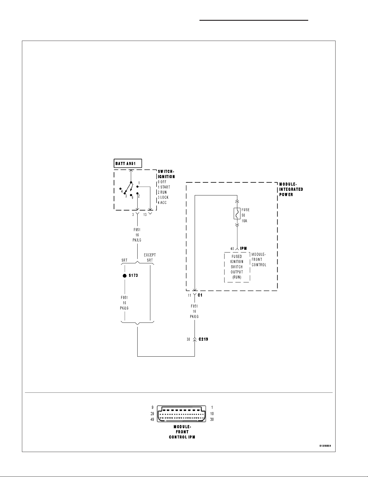
For a complete wiring diagram Refer to Section 8W.
• When Monitored:
With the ignition on.
• Set Condition:
The FCM detects an ignition run/start mismatch.
Possible Causes
INSTRUMENT CLUSTER
POWER DISTRIBUTION CENTER
FRONT CONTROL MODULE
Diagnostic Test
CHECK FOR AN ACTIVE DTC
1.
Turn the ignition on.
With the DRB, erase the FCM DTC’s.
Turn the ignition off then turn the ignition on and wait approximately 1 minute.
With the DRB, read the FCM DTC’s.
Did this DTC reset?
Yes >>
No >>
CHECK THE STATUS OF THE INSTRUMENT CLUSTER
2.
NOTE: Ensure the battery is fully charged before proceeding with this test.
NOTE: Diagnose and repair any Airbag, Instrument Cluster, or PCM DTCs before proceeding with this test.
With the DRB, select MIC, Monitors and observe the ignition state.
While observing the ignition state, start the vehicle.
Does the DRB display run and start when the ignition switch is in those positions?
Yes >>
No >>
Go To 2
The condition that set this DTC is no longer present. Using the wiring diagram/schematic as a guide,
inspect the wiring for chafed, pierced, pinched, and partially broken wires and the wiring harness connectors for broken, bent, pushed out, and corroded terminals.
Go To 3
Replace and program the Instrument Cluster in accordance with the service information.
Perform BODY VERIFICATION TEST - VER 1. (Refer to BODY VERIFICATION TEST - VER 1.)
Page 4
8I - 4 IGNITION CONTROL - ELECTRICAL DIAGNOSTICS DR/DH
IGNITION RUN/START MISMATCH (FCM) (CONTINUED)
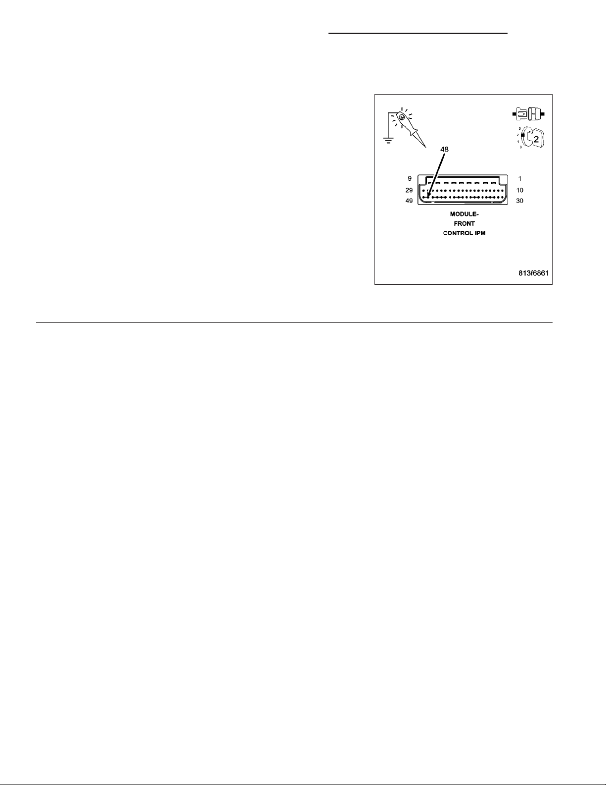
CHECK THE FUSED IGNITION SWITCH OUTPUT CIRCUIT
3.
NOTE: Check IPM fuse #50 for an open before proceeding with
this test.
Turn the ignition off.
Remove the FCM from the IPM.
Turn the ignition on.
Using a 12-volt test light connected to ground, probe the Fused Igni-
tion Switch Output circuit (cavity 48).
Is the test light illuminated?
Yes >>
No >>
Replace the Front Control Module in accordance with the
service information.
Perform BODY VERIFICATION TEST - VER 1. (Refer to
BODY VERIFICATION TEST - VER 1.)
Replace the Power Distribution Center in accordance with
the service information.
Perform BODY VERIFICATION TEST - VER 1. (Refer to
BODY VERIFICATION TEST - VER 1.)
Page 5

DR/DH IGNITION CONTROL - SERVICE INFORMATION 8I - 5
IGNITION CONTROL - SERVICE INFORMATION
TABLE OF CONTENTS
page page
IGNITION CONTROL - SERVICE INFORMATION
DESCRIPTION ..........................5
SPECIFICATIONS
TORQUE .............................7
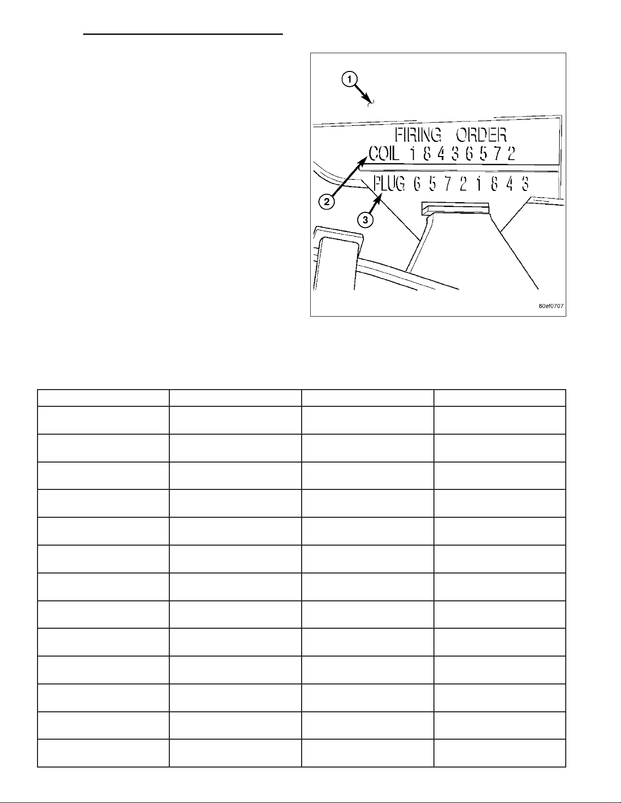
ENGINE FIRING ORDER - 3.7L V-6 .........8
ENGINE FIRING ORDER – 4.7L V-8 ........8
FIRING ORDER / CABLE ROUTING – 5.7L
V-8 ENGINE ...........................8
8.3L - FIRING ORDER ...................9
SPARK PLUG CABLE RESISTANCE .......10
SPARK PLUGS .......................10
IGNITION COIL RESISTANCE - 3.7L V-6 ....10
IGNITION COIL RESISTANCE - 4.7L V-8 ....10
IGNITION COIL RESISTANCE - 5.7L V-8 ....11
IGNITION COIL RESISTANCE - 8.3L V-10 . . . 11
IGNITION TIMING .....................11
RELAY-AUTO SHUT DOWN
DESCRIPTION - PCM OUTPUT .............11
OPERATION
OPERATION - PCM OUTPUT .............11
OPERATION - ASD SENSE - PCM INPUT . . . 11
DIAGNOSIS AND TESTING - ASD AND FUEL
PUMP RELAYS .......................11
REMOVAL .............................13
INSTALLATION .........................13
SENSOR-CAMSHAFT POSITION
DESCRIPTION .........................13
OPERATION
OPERATION .........................14
8.3L V-10 ............................16
REMOVAL
REMOVAL ...........................17
8.3L - REPLACING WITH NEW SENSOR ....19
8.3 L - REPLACING OLD SENSOR WITH
ORIGINAL ...........................20
INSTALLATION
INSTALLATION .......................20
8.3L - INSTALLATION - WITH NEW SENSOR . 21
8.3L - REPLACING OLD SENSOR WITH
ORIGINAL ...........................21
IGNITION COIL
DESCRIPTION .........................23
OPERATION ...........................25
REMOVAL
REMOVAL ...........................26
8.3L - SRT-10 .........................29
INSTALLATION
INSTALLATION .......................30
8.3L - SRT-10 .........................31
SENSOR-KNOCK
DESCRIPTION .........................31
OPERATION ...........................31
REMOVAL .............................32
INSTALLATION .........................33
SPARK PLUG
DESCRIPTION .........................34
REMOVAL .............................34
CLEANING
CLEANING AND ADJUSTMENT ...........35
INSTALLATION .........................35
IGNITION COIL CAPACITOR
DESCRIPTION .........................36
OPERATION ...........................36
REMOVAL .............................36
INSTALLATION .........................37
SPARK PLUG CABLE
DESCRIPTION .........................37
OPERATION ...........................37
REMOVAL
REMOVAL ...........................37
8.3L - SRT-10 .........................38
INSTALLATION
INSTALLATION .......................38
8.3L - SRT-10 .........................39
PUSH-BUTTON STARTER SWITCH
DESCRIPTION .........................40
REMOVAL .............................41
INSTALLATION .........................41
IGNITION CONTROL - SERVICE INFORMATION
DESCRIPTION
The ignition system is controlled by the Powertrain Control Module (PCM) on all engines.
3.7L V-6 ENGINE
The 3.7L V-6 engine uses a separate ignition coil for each cylinder. The one-piece coil bolts directly to the cylinder
head. Rubber boots seal the secondary terminal ends of the coils to the top of all 6 spark plugs. A separate electrical connector is used for each coil.
Page 6

8I - 6 IGNITION CONTROL - SERVICE INFORMATION DR/DH
Because of coil design, spark plug cables (secondary cables) are not used. A distributor is not used with the 3.7L
engine.
Two knock sensors (one for each cylinder bank) are used to help control spark knock.
The Auto Shutdown (ASD) relay provides battery voltage to each ignition coil.
The ignition system consists of:
• 6 Spark Plugs
• 6 Separate Ignition Coils
• 2 Knock Sensors
• Powertrain Control Module (PCM)
• Also to be considered part of the ignition system are certain inputs from the Crankshaft Position, Camshaft
Position, Throttle Position, 2 knock and MAP Sensors
4.7L V-8 ENGINE
The 4.7L V-8 engine uses a separate ignition coil for each cylinder. The one-piece coil bolts directly to the cylinder
head. Rubber boots seal the secondary terminal ends of the coils to the top of all 8 spark plugs. A separate electrical connector is used for each coil.
Because of coil design, spark plug cables (secondary cables) are not used. A distributor is not used with the 4.7L
engine.
Two knock sensors (one for each cylinder bank) are used to help control spark knock.
The Auto Shutdown (ASD) relay provides battery voltage to each ignition coil.
The ignition system consists of:
• 8 Spark Plugs
• 8 Separate Ignition Coils
• 2 Knock Sensors
• Powertrain Control Module (PCM)
• Also to be considered part of the ignition system are certain inputs from the Crankshaft Position, Camshaft
Position, Throttle Position, 2 knock and MAP Sensors
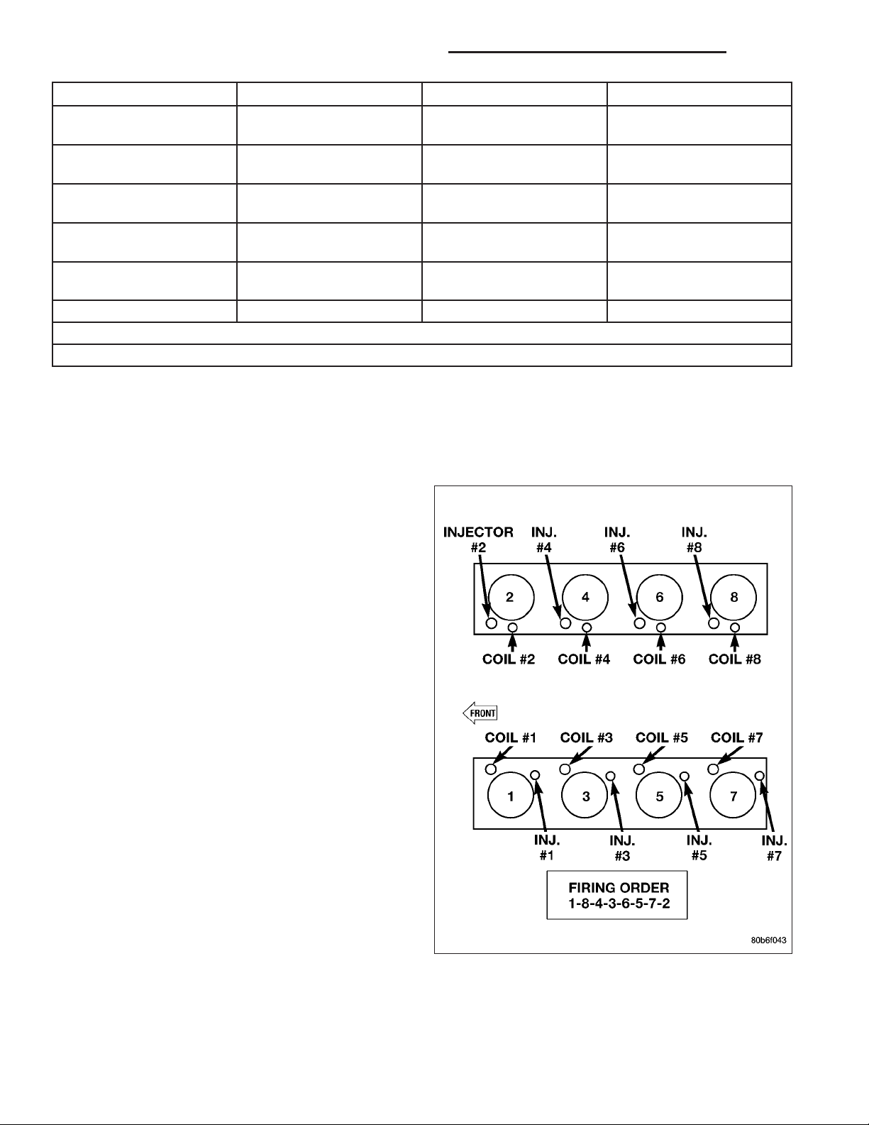
5.7L V-8 ENGINE
For additional information, also refer to Ignition Coil Description and Operation.
The 5.7L V-8 engine is equipped with 16 spark plugs. Two plugs are used for each cylinder. The 5.7L is also
equipped with 8 separate and independent ignition coils. The one-piece coil bolts directly to the cylinder head cover
and attaches the coils secondary output terminal directly to a spark plug using a rubber boot seal. Each coil is also
equipped with a second output terminal. This second terminal connects a conventional spark plug cable directly to
a spark plug on the opposite cylinder bank. A separate primary electrical connector is used for each coil.
Eight conventional spark plug cables are used with the 5.7L. These cables connect a coil on one cylinder bank,
directly to a spark plug on the opposite cylinder bank. The cables are placed and routed in a special plastic loom
to keep them separated. This loom is clipped to the intake manifold. To prevent a miss-match of cables, a corresponding spark plug / coil number is displayed on each plug cable: 1/6, 2/3, 4/7 and 5/8. These numbers can also
be found on the top of the intake manifold to the right of the throttle body.
Two knock sensors (one for each cylinder bank) are used to help control spark knock.
The 5.7L engine will not use a conventional distributor.
Page 7
DR/DH IGNITION CONTROL - SERVICE INFORMATION 8I - 7
The ignition system consists of:
• 16 Spark Plugs (2 per cylinder)
• 8 Separate, Dual-Secondary Output, Ignition
Coils
• 2 Knock Sensors
• 8 Secondary Ignition Cables
• Powertrain Control Module (PCM)
• Also to be considered part of the ignition system
are certain inputs from the Crankshaft Position,
Camshaft Position, Throttle Position, 2 knock and
MAP Sensors
SPECIFICATIONS
TORQUE
DESCRIPTION N·m Ft. Lbs. In. Lbs.
Camshaft Position Sensor
- 3.7L V-6 Engine
Camshaft Position Sensor
- 4.7L V-8 Engine
Camshaft Position Sensor
- 5.7L V-8 Engine
Camshaft Position Sensor
- 8.3L Engine
Crankshaft Position
Sensor - 3.7L V-6 Engine
Crankshaft Position
Sensor - 4.7L V-8 Engine
Crankshaft Position
Sensor - 5.7L V-8 Engine
Crankshaft Position
Sensor - 8.3L Engine
Ignition Coil Mounting -
3.7L V-6 Engine
Ignition Coil Mounting -
4.7L V-8 Engine
Ignition Coil Mounting -
5.7L V-8 Engine
Ignition Coil to Cyl. Head
Screws 8.3L Engine
* Knock Sensor - 3.7L V-6
Engine
12 - 106
12 - 106
12 9 105
10.7 - 95
28 21 205
28 21 205
12 9 105
10.7 - 95
8-70
8-70
12 9 105 (± 20)
10.7 - 95
20 15 176
Page 8
8I - 8 IGNITION CONTROL - SERVICE INFORMATION DR/DH
DESCRIPTION N·m Ft. Lbs. In. Lbs.
* Knock Sensor - 4.7L V-8
Engine
* Knock Sensor - 5.7L V-8
Engine
Spark Plugs - 3.7L V-6
Engine
Spark Plugs - 4.7L V-8
Engine
** Spark Plugs - 5.7L V-8
Engine
Spark Plugs - 8.3L Engine 27 20 -
* Do not apply any sealant, thread-locker or adhesive to bolts. Poor sensor performance may result.
** Torque critical tapered design. Do not exceed 15 ft. lbs.
20 15 176
20 15 176
27 20 -
27 20 -
18 (± 3) 13 (± 2) -
ENGINE FIRING ORDER - 3.7L V-6
1-6-5-4-3-2
ENGINE FIRING ORDER – 4.7L V-8
FIRING ORDER / CABLE ROUTING –
5.7L V-8 ENGINE
Eight conventional spark plug cables are used with the
5.7L. These cables connect a coil on one cylinder
bank, directly to a spark plug on the opposite cylinder
bank. The cables are placed and routed in a special
plastic loom to keep them separated. This loom is
clipped to the intake manifold. To prevent a missmatch of cables, a corresponding spark plug / coil
number is displayed on each plug cable: 1/6, 2/3, 4/7
and 5/8. These numbers can also be found on the top
of the intake manifold to the right of the throttle body.
Page 9
DR/DH IGNITION CONTROL - SERVICE INFORMATION 8I - 9
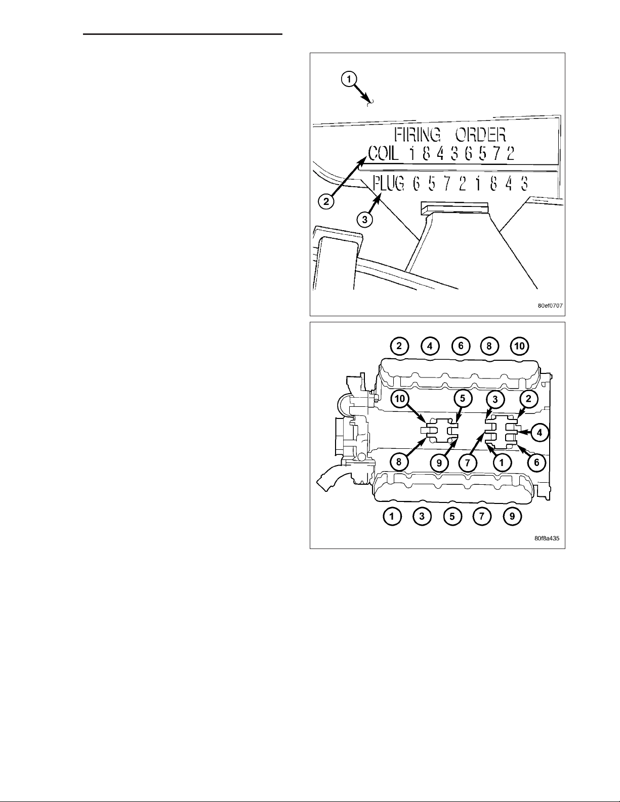
8.3L - FIRING ORDER
1-10-9-4-3-6-5-8-7-2
Page 10
8I - 10 IGNITION CONTROL - SERVICE INFORMATION DR/DH
SPARK PLUG CABLE RESISTANCE
Except 8.3L V-10
MINIMUM MAXIMUM
250 Ohms Per Inch 1000 Ohms Per Inch
3000 Ohms Per Foot 12,000 Ohms Per Foot
8.3L V - 10
MINIMUM MAXIMUM
250 Ohms Per Inch 750 Ohms Per Inch
3000 Ohms Per Foot 9,000 Ohms Per Foot
SPARK PLUGS
ENGINE PLUG TYPE ELECTRODE GAP
3.7L V-6 ZFR6F - 11G (NGK) 1.1 (0.042 in.)
4.7L V-8 RC12MCC4 1.01 mm (.040 in.)
5.7L V-8 Champion - RE14MCC4 1.14 mm (.045 in.)
8.3L V-10 RC12ECC 0.033 to 0.038
IGNITION COIL RESISTANCE - 3.7L V-6
PRIMARY RESISTANCE
21-27°C (70-80°F)
0.6 - 0.9 Ohms 6,000 - 9,000 Ohms
SECONDARY
RESISTANCE 21-27°C
(70-80°F)
IGNITION COIL RESISTANCE - 4.7L V-8
PRIMARY
RESISTANCE 21-27°C
(70-80°F)
0.6 - 0.9 Ohms 6,000 - 9,000 Ohms
SECONDARY
RESISTANCE 21-27°C
(70-80°F)
Page 11
DR/DH IGNITION CONTROL - SERVICE INFORMATION 8I - 11
IGNITION COIL RESISTANCE - 5.7L V-8
PRIMARY RESISTANCE @ 21-27°C (70-80°F)
0.558 - 0.682 Ohms
(Plus or Minus 10% @ 70-80° F)
IGNITION COIL RESISTANCE - 8.3L V-10
Coil Manufacture
Diamond 0.53 to 0.65 Ohms 10,900 to 14,700 Ohms
Primary Resistance at 21°C-27°C
(70°F-80°F)
Secondary Resistance at 21°C-27°C
(70°F-80°F)
IGNITION TIMING
Ignition timing is not adjustable on any engine.
RELAY-AUTO SHUT DOWN
DESCRIPTION - PCM OUTPUT
The 5–pin, 12–volt, Automatic Shutdown (ASD) relay is located in the Power Distribution Center (PDC). Refer to
label on PDC cover for relay location.
OPERATION
OPERATION - PCM OUTPUT
The ASD relay supplies battery voltage (12+ volts) to the fuel injectors and ignition coil(s). With certain emissions
packages it also supplies 12–volts to the oxygen sensor heating elements.
The ground circuit for the coil within the ASD relay is controlled by the Powertrain Control Module (PCM). The PCM
operates the ASD relay by switching its ground circuit on and off.
The ASD relay will be shut–down, meaning the 12–volt power supply to the ASD relay will be de-activated by the
PCM if:
• the ignition key is left in the ON position. This is if the engine has not been running for approximately 1.8
seconds.
• there is a crankshaft position sensor signal to the PCM that is lower than pre-determined values.
OPERATION - ASD SENSE - PCM INPUT
A 12 volt signal at this input indicates to the PCM that the ASD has been activated. The relay is used to connect the
oxygen sensor heater element, ignition coil and fuel injectors to 12 volt + power supply.
This input is used only to sense that the ASD relay is energized. If the Powertrain Control Module (PCM) does not
see 12 volts at this input when the ASD should be activated, it will set a Diagnostic Trouble Code (DTC).
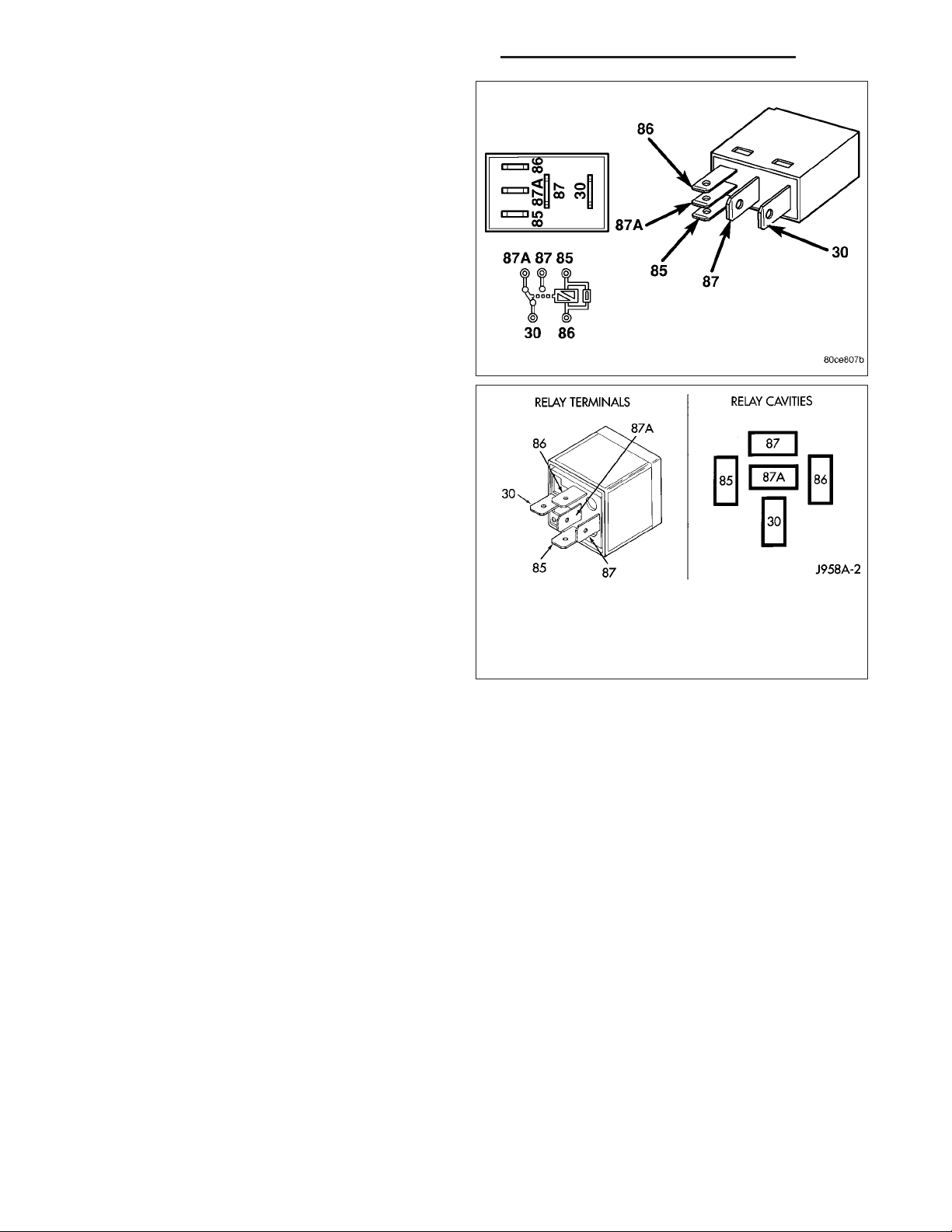
DIAGNOSIS AND TESTING - ASD AND FUEL PUMP RELAYS
The following description of operation and tests apply only to the Automatic Shutdown (ASD) and fuel
pump relays. The terminals on the bottom of each relay are numbered. Two different types of relays may be used,
or.
Page 12
8I - 12 IGNITION CONTROL - SERVICE INFORMATION DR/DH
• Terminal number 30 is connected to battery voltage. For both the ASD and fuel pump relays, terminal 30 is connected to battery voltage at all
times.
• The PCM grounds the coil side of the relay
through terminal number 85.
• Terminal number 86 supplies voltage to the coil
side of the relay.
• When the PCM de-energizes the ASD and fuel
pump relays, terminal number 87A connects to
terminal 30. This is the Off position. In the off
position, voltage is not supplied to the rest of the
circuit. Terminal 87A is the center terminal on the
relay.
• When the PCM energizes the ASD and fuel
pump relays, terminal 87 connects to terminal
30. This is the On position. Terminal 87 supplies
voltage to the rest of the circuit.
The following procedure applies to the ASD and fuel
pump relays.
1. Remove relay from connector before testing.
2. With the relay removed from the vehicle, use an
ohmmeter to check the resistance between terminals 85 and 86. The resistance should be 75 ohms
+/- 5 ohms.
3. Connect the ohmmeter between terminals 30 and
87A. The ohmmeter should show continuity
between terminals 30 and 87A.
4. Connect the ohmmeter between terminals 87 and
30. The ohmmeter should not show continuity at
this time.
5. Connect one end of a jumper wire (16 gauge or smaller) to relay terminal 85. Connect the other end of the
jumper wire to the ground side of a 12 volt power source.
6. Connect one end of another jumper wire (16 gauge or smaller) to the power side of the 12 volt power source. Do
not attach the other end of the jumper wire to the relay at this time.
WARNING: DO NOT ALLOW OHMMETER TO CONTACT TERMINALS 85 OR 86 DURING THIS TEST. DAMAGE
TO OHMMETER MAY RESULT.
7. Attach the other end of the jumper wire to relay terminal 86. This activates the relay. The ohmmeter should now
show continuity between relay terminals 87 and 30. The ohmmeter should not show continuity between relay
terminals 87A and 30.
8. Disconnect jumper wires.
9. Replace the relay if it did not pass the continuity and resistance tests. If the relay passed the tests, it operates
properly. Check the remainder of the ASD and fuel pump relay circuits. Refer to 8, Wiring Diagrams.
Page 13
DR/DH IGNITION CONTROL - SERVICE INFORMATION 8I - 13
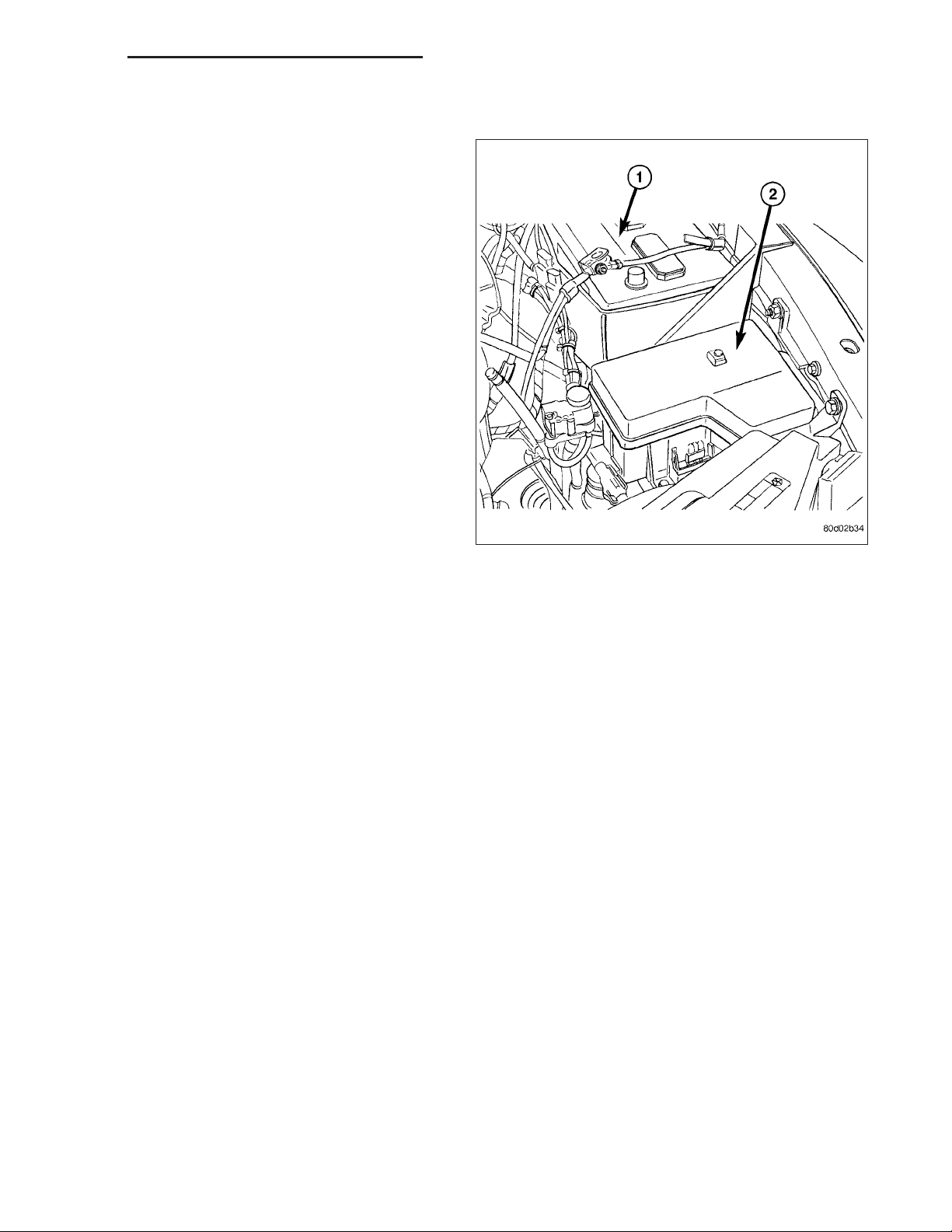
REMOVAL
The ASD relay is located in the Power Distribution
Center (PDC) (2) . Refer to label on PDC cover for
relay location.
1. Remove PDC cover.
2. Remove relay from PDC.
3. Check condition of relay terminals and PDC connector terminals for damage or corrosion. Repair if
necessary before installing relay.
4. Check for pin height (pin height should be the
same for all terminals within the PDC connector).
Repair if necessary before installing relay.
INSTALLATION
The ASD relay is located in the Power Distribution Center (PDC). Refer to label on PDC cover for relay location.
1. Install relay to PDC.
2. Install cover to PDC.
SENSOR-CAMSHAFT POSITION
DESCRIPTION
3.7L V-6
The Camshaft Position Sensor (CMP) on the 3.7L 6-cylinder engine is bolted to the right-front side of the right cylinder head.
4.7L V-8
The Camshaft Position Sensor (CMP) on the 4.7L V-8 engine is bolted to the right-front side of the right cylinder
head.
5.7L V-8
The Camshaft Position Sensor (CMP) on the 5.7L V-8 engine is located below the generator on the timing chain /
case cover on the right/front side of engine.
5.9L Diesel
The Camshaft Position Sensor (CMP) on the 5.9L diesel engine is located below the fuel injection pump. It is bolted
to the back of the timing gear cover.
Page 14

8I - 14 IGNITION CONTROL - SERVICE INFORMATION DR/DH
OPERATION
OPERATION
3.7L V-6
The Camshaft Position Sensor (CMP) sensor (3) on
the 3.7L V-6 engine contains a hall effect device
referred to as a sync signal generator. A rotating target
wheel (tonewheel) for the CMP is located at the front
of the camshaft for the right cylinder head. This sync
signal generator detects notches (1) located on a
tonewheel. As the tonewheel rotates, the notches pass
through the sync signal generator. The signal from the
CMP sensor is used in conjunction with the Crankshaft
Position Sensor (CKP) to differentiate between fuel
injection and spark events. It is also used to synchronize the fuel injectors with their respective cylinders.
When the leading edge of the tonewheel notch enters
the tip of the CMP, the interruption of magnetic field
causes the voltage to switch high, resulting in a sync
signal of approximately 5 volts.
When the trailing edge of the tonewheel notch leaves
then tip of the CMP, the change of the magnetic field
causes the sync signal voltage to switch low to 0
volts.
4.7L V-8
The CMP sensor (3) on the 4.7L engine contains a
hall effect device called a sync signal generator to
generate a fuel sync signal. This sync signal generator
detects notches (1) located on a tonewheel. The tonewheel is located at the front of the camshaft for the
right cylinder head. As the tonewheel rotates, the
notches pass through the sync signal generator. The
pattern of the notches (viewed counter-clockwise from
front of engine) is: 1 notch, 2 notches, 3 notches, 3
notches, 2 notches 1 notch, 3 notches and 1 notch.
The signal from the CMP sensor is used in conjunction with the crankshaft position sensor to differentiate
between fuel injection and spark events. It is also
used to synchronize the fuel injectors with their
respective cylinders.
Page 15

DR/DH IGNITION CONTROL - SERVICE INFORMATION 8I - 15
5.7L V-8
The CMP sensor is used in conjunction with the crankshaft position sensor to differentiate between fuel
injection and spark events. It is also used to synchronize the fuel injectors with their respective cylinders.
The sensor generates electrical pulses. These pulses
(signals) are sent to the Powertrain Control Module
(PCM). The PCM will then determine crankshaft position from both the camshaft position sensor and crankshaft position sensor.
The tonewheel (2) is located at the front of the camshaft. As the tonewheel rotates, notches (3) pass
through the sync signal generator.
When the cam gear is rotating, the sensor will detect
the notches. Input voltage from the sensor to the PCM
will then switch from a low (approximately 0.3 volts) to
a high (approximately 5 volts). When the sensor
detects a notch has passed, the input voltage
switches back low to approximately 0.3 volts.
5.9L Diesel
The Camshaft Position Sensor (CMP) (1) contains a
hall effect device. A rotating target wheel (tonewheel)
for the CMP is located on the front timing gear. This
hall effect device detects notches located on the tonewheel. As the tonewheel rotates, the notches pass the
tip of the CMP.
When the leading edge of the tonewheel notch passes
the tip of the CMP, the following occurs: The interruption of magnetic field causes the voltage to switch
high resulting in a signal of approximately 5 volts.
When the trailing edge of the tonewheel notch passes
the tip of the CMP, the following occurs: The change
of the magnetic field causes the signal voltage to
switch low to 0 volts.
The CMP provides a signal to the Engine Control
Module (ECM) at all times when the engine is running.
The ECM uses the CMP information primarily on
engine start-up. Once the engine is running, the ECM
uses the CMP as a backup sensor for engine speed.
The Crankshaft Position Sensor (CKP) is the primary
engine speed indicator for the engine after the engine
is running.
Page 16

8I - 16 IGNITION CONTROL - SERVICE INFORMATION DR/DH
8.3L V-10
The Camshaft Position Sensor is located above the
water pump and under the throttle body.
The camshaft position sensor (1) provides cylinder
identification to the Powertrain Control Module (PCM).
The sensor generates pulses. The PCM determines
crankshaft position from the camshaft position sensor
and crankshaft position sensor inputs. The PCM uses
the input to determine fuel injection synchronization
and to determine which ignition coil to energize.
Page 17

DR/DH IGNITION CONTROL - SERVICE INFORMATION 8I - 17
The camshaft position sensor detects when a step
down (1) in the camshaft sprocket passes beneath it.
When the sensor detects the step down, the input
voltage from the sensor to the PCM switches from low
(0.3 volts) to high (5 volts). As the step up returns to
the sensor, the input voltage switches back to low (0.3
volts). The paper spacer is not used on 8.3L
motors. Don’t use at all. It plugs up the oil pickup
screen..
REMOVAL
REMOVAL
3.7L V-6
The Camshaft Position Sensor (CMP) on the 3.7L V-6
engine is bolted to the front/top of the right cylinder
head (3).
1. Disconnect electrical connector at CMP sensor.
2. Remove sensor mounting bolt (2).
3. Carefully twist sensor from cylinder head.
4. Check condition of sensor o-ring.
Page 18

8I - 18 IGNITION CONTROL - SERVICE INFORMATION DR/DH
4.7L V-8
The Camshaft Position Sensor (CMP) (2) on the 4.7L
V–8 engine is bolted to the front/top of the right cylinder head.
1. Raise and support vehicle.
2. Disconnect electrical connector at CMP sensor.
3. Remove sensor mounting bolt (3).
4. Carefully twist sensor from cylinder head.
5. Check condition of sensor o-ring.
5.7L V-8
The Camshaft Position Sensor (CMP) (2) on the 5.7L
V-8 engine is located on right side of timing chain
cover below generator (1).
1. Disconnect electrical connector (3) at CMP sensor.
Page 19

DR/DH IGNITION CONTROL - SERVICE INFORMATION 8I - 19
2. Remove sensor mounting bolt (3).
3. Carefully twist sensor from cylinder head.
4. Check condition of sensor o-ring.
5.9L Diesel
The Camshaft Position Sensor (CMP) on the 5.9L diesel engine is located below the fuel injection pump (1).
It is bolted to the back of the timing gear cover.
1. Disconnect electrical connector (5) at CMP sensor.
2. Remove sensor mounting bolt (6).
3. Carefully twist sensor from timing gear cover.
4. Check condition of sensor o-ring.
8.3L - REPLACING WITH NEW SENSOR
The camshaft position sensor is located on the timing chain case above the water pump and under the throttle body.
If a new replacement camshaft position sensor is to be installed, use this procedure.
1. Disconnect the sensor wiring harness connector from sensor.
2. Remove the sensor mounting bolt.
3. Carefully pry the sensor from the timing chain case/cover in a rocking action with two small screwdrivers.
4. Remove the sensor from vehicle.
Page 20

8I - 20 IGNITION CONTROL - SERVICE INFORMATION DR/DH
8.3 L - REPLACING OLD SENSOR WITH ORIGINAL
The camshaft position sensor is located on the timing chain case above the water pump and under the throttle body.
If the original camshaft position sensor is to be removed and installed, such as when servicing the timing chain,
timing gears or timing chain cover, use this procedure.
1. Disconnect the sensor harness connector from the sensor.
2. Scribe the sensor for location depth.
3. Remove the sensor mounting bolt.
4. Carefully pry the sensor from the timing chain case/cover in a rocking action with two small screwdrivers.
5. Remove the sensor from vehicle.
6. Check condition of sensor o-ring.
INSTALLATION
INSTALLATION
3.7L V-6
The Camshaft Position Sensor (CMP) on the 3.7L V-6
engine is bolted to the front/top of the right cylinder
head.
1. Clean out machined hole in cylinder head.
2. Apply a small amount of engine oil to sensor
o-ring.
3. Install sensor into cylinder head with a slight rocking and twisting action.
CAUTION: Before tightening sensor mounting bolt, be sure sensor is completely flush to cylinder head. If
sensor is not flush, damage to sensor mounting tang may result.
4. Install mounting bolt and tighten. Refer to torque specifications.
5. Connect electrical connector to sensor.
4.7L V-8
The Camshaft Position Sensor (CMP) on the 4.7L V-8 engine is bolted to the front/top of the right cylinder head.
1. Clean out machined hole in cylinder head.
2. Apply a small amount of engine oil to sensor o-ring.
3. Install sensor into cylinder head with a slight rocking action. Do not twist sensor into position as damage to o-ring
may result.
CAUTION: Before tightening sensor mounting bolt, be sure sensor is completely flush to cylinder head. If
sensor is not flush, damage to sensor mounting tang may result.
4. Install mounting bolt and tighten. Refer to Torque Specifications.
5. Connect electrical connector to sensor.
5.7L V-8
The Camshaft Position Sensor (CMP) on the 5.7L V-8 engine is bolted to the right / front side of the timing chain
cover or.
1. Clean out machined hole in cylinder head.
2. Apply a small amount of engine oil to sensor o-ring.
3. Install sensor into cylinder head with a slight rocking action. Do not twist sensor into position as damage to o-ring
may result.
Page 21

DR/DH IGNITION CONTROL - SERVICE INFORMATION 8I - 21
CAUTION: Before tightening sensor mounting bolt, be sure sensor is completely flush to timing chain cover.
If sensor is not flush, damage to sensor mounting tang may result.
4. Install mounting bolt and tighten. Refer to Torque Specifications.
5. Connect electrical connector to sensor.
5.9L Diesel
The CMP is located on the back of the timing gear cover.
1. Clean out machined hole in back of timing gear cover.
2. Apply a small amount of engine oil to sensor o-ring.
3. Install sensor into timing gear cover with a slight rocking action. Do not twist sensor into position as damage to
o-ring may result.
CAUTION: Before tightening sensor mounting bolt, be sure sensor is completely flush to back of timing
chain cover. If sensor is not flush, damage to sensor mounting tang may result.
4. Install mounting bolt and tighten. Refer to Torque Specifications.
5. Connect electrical connector to sensor.
8.3L - INSTALLATION - WITH NEW SENSOR
The camshaft position sensor is located on the timing chain case above the water pump and under the throttle body.
1. Apply a small amount of engine oil to the sensor o-ring.
A low (step down) and high (step up) area are machined into the camshaft drive gear. The sensor is positioned in
the timing gear cover so that a small air gap exists between the face of sensor and the high machined area of cam
gear.
Before the sensor is installed, the cam gear may have to be rotated. This is to allow the high machined area (step
up) on the gear to be directly in front of the sensor mounting hole opening on the timing gear cover.
Do not install sensor with gear positioned at low area. When the engine is started, the sensor will be broken.
2. Using a 1/2 in. wide metal ruler, measure the distance from the cam gear to the face of the sensor mounting hole
opening on the timing gear cover.
3. If the dimension is approximately 1–15/32 inches or less, it is OK to install sensor.
4. If the dimension is approximately 1–5/8 inches or more, the cam gear will have to be rotated.
5. Attach a socket to the vibration damper mounting bolt and rotate engine until the 1–15/32 inch dimension is
attained.
6. Install the sensor into the timing case/cover with a slight rocking action. Do not twist the sensor into position as
damage to the o-ring may result. Push the sensor all the way into the cover until the rib material on the sensor
contacts the camshaft gear.
7. Install the mounting bolt and tighten to 10.7 N·m (95 in. lbs.) torque.
8. Connect sensor wiring harness to engine harness.
When the engine is started, the rib material will be sheared off the face of sensor. This will automatically set sensor
air gap.
8.3L - REPLACING OLD SENSOR WITH ORIGINAL
The camshaft position sensor is located on the timing chain case above the water pump and under the throttle body.
When installing a used camshaft position sensor, the sensor depth must be adjusted to prevent contact with the
camshaft gear (sprocket).
1. Apply a small amount of engine oil to the sensor o-ring.
A low and high area are machined into the camshaft drive gear. The sensor is positioned in the timing gear cover
so that a small air gap exists between the face of sensor and the high machined area of cam gear.
Page 22

8I - 22 IGNITION CONTROL - SERVICE INFORMATION DR/DH
Before the sensor is installed, the cam gear may have
to be rotated. This is to allow the high machined area
on the gear to be directly in front of the sensor mounting hole opening on the timing gear cover.
Do not install sensor with gear positioned at low
area. When the engine is started, the sensor will
be broken.
2. Using a 1/2 in. wide metal ruler, measure the distance from the cam gear to the face of the sensor
mounting hole opening on the timing gear cover.
3. If the dimension is approximately 1–15/32 inches or
less, it is OK to install sensor.
4. If the dimension is approximately 1–5/8 inches or
more, the cam gear will have to be rotated.
5. Attach a socket to the vibration damper mounting
bolt and rotate engine until the 1–15/32 inch
dimension is attained.
6. Install the sensor into the timing case/cover with a
slight rocking action until the sensor is aligned to
scribe line. The paper spacer can be used if reinstalling a used sensor.
7. Install sensor mounting bolt and tighten to 10.7
N·m (95 in. lbs.) torque.
8. Connect engine wiring harness to sensor.
Page 23

DR/DH IGNITION CONTROL - SERVICE INFORMATION 8I - 23
IGNITION COIL
DESCRIPTION
3.7L V-6
The 3.7L V-6 engine uses 6 dedicated, and individually fired coil (1) for each spark plug.
Each coil (1) is mounted directly into the cylinder head
and onto the top of each spark plug.
Page 24

8I - 24 IGNITION CONTROL - SERVICE INFORMATION DR/DH
4.7L V-8
The 4.7L V–8 engine uses 8 dedicated, and individually fired coil for each spark plug (1). Each coil is
mounted directly to the top of each spark plug.
5.7L V-8
The 5.7L V–8 engine uses 8 dedicated, and individually fired coil (1) for each pair of spark plugs.
Page 25

DR/DH IGNITION CONTROL - SERVICE INFORMATION 8I - 25
Each coil (5) is mounted directly to the top of each
spark plug. Each coil is bolted (6) to the valve cover.
OPERATION
3.7L V-6
Battery voltage is supplied to the 6 individual ignition coils from the ASD relay. The Powertrain Control Module
(PCM) opens and closes each ignition coil ground circuit at a determined time for ignition coil operation.
Base ignition timing is not adjustable. By controlling the coil ground circuit, the PCM is able to set the base
timing and adjust the ignition timing advance. This is done to meet changing engine operating conditions.
The ignition coil is not oil filled. The windings are embedded in an epoxy compound. This provides heat and vibration resistance that allows the ignition coil to be mounted on the engine.
Because of coil design, spark plug cables (secondary cables) are not used with the 3.7L V-6 engine.
4.7L V-8
Battery voltage is supplied to the 8 individual ignition coils from the ASD relay. The Powertrain Control Module
(PCM) opens and closes each ignition coil ground circuit at a determined time for ignition coil operation.
Base ignition timing is not adjustable. By controlling the coil ground circuit, the PCM is able to set the base
timing and adjust the ignition timing advance. This is done to meet changing engine operating conditions.
The ignition coil is not oil filled. The windings are embedded in an epoxy compound. This provides heat and vibration resistance that allows the ignition coil to be mounted on the engine.
Because of coil design, spark plug cables (secondary cables) are not used with the 4.7L V-8 engine.
5.7L V-8
The ignition system is controlled by the Powertrain Control Module (PCM) on all engines.
A “wasted spark” system is used on the 5.7L engine combining paired, or dual-firing coils, and 2 spark plugs per
cylinder. The coils and spark plugs are connected with paired, secondary high-voltage cables.
Each cylinder is equipped with 1 dual-output coil. Meaning one coil mounts directly over one of the dual spark plugs
for 1 high-voltage output. A second high-voltage output is supplied directly from the same coil (using a plug cable)
to one of the dual spark plugs on a corresponding (paired) cylinder on the opposite cylinder bank.
Each coil fires 2 spark plugs simultaneously on each of the cylinder banks (one cylinder on compression stroke and
one cylinder on exhaust stroke). EXAMPLE : When the #1 cylinder is on compression stroke and ready for spark,
the #1 coil will fire one of the dual spark plugs on the #1 cylinder (directly below the coil). The other dual spark plug
on the #1 cylinder will be fired by the #6 coil. At the same time, the #1 coil will fire a “wasted spark” to one of the
Page 26

8I - 26 IGNITION CONTROL - SERVICE INFORMATION DR/DH
dual spark plugs at the #6 cylinder as coil #6 also fires a “wasted spark” to one of the dual spark plugs at the #6
cylinder.
The firing order is paired at cylinders 1/6, 2/3, 4/7, 5/8. Basic cylinder firing order is 1–8–4–3–6–5–7–2.
Battery voltage is supplied to all of the ignition coils positive terminals from the ASD relay. If the PCM does not see
a signal from the crankshaft and camshaft sensors (indicating the ignition key is ON but the engine is not running),
it will shut down the ASD circuit.
Base ignition timing is not adjustable on the 5.7L V-8 engine. By controlling the coil ground circuits, the PCM is
able to set the base timing and adjust the ignition timing advance. This is done to meet changing engine operating
conditions.
The PCM adjusts ignition timing based on inputs it receives from:
• The engine coolant temperature sensor
• The crankshaft position sensor (engine speed)
• The camshaft position sensor (crankshaft position)
• The manifold absolute pressure (MAP) sensor
• The throttle position sensor
• Transmission gear selection
REMOVAL
REMOVAL
3.7L V-6
An individual ignition coil (2) is used for each spark
plug. The coil fits into machined holes in the cylinder
head. A mounting stud/nut secures each coil to the top
of the intake manifold. The bottom of the coil is
equipped with a rubber boot to seal the spark plug to
the coil. Inside each rubber boot is a spring. The
spring is used for a mechanical contact between the
coil and the top of the spark plug. These rubber boots
and springs are a permanent part of the coil and are
not serviced separately. An o-ring is used to seal the
coil at the opening into the cylinder head.
1. Depending on which coil is being removed, the
throttle body air intake tube or intake box may
need to be removed to gain access to coil.
Page 27

DR/DH IGNITION CONTROL - SERVICE INFORMATION 8I - 27
2. Disconnect electrical connector from coil by pushing downward on release lock on top of connector
and pull connector from coil.
3. Clean area at base of coil with compressed air
before removal.
4. Remove coil mounting nut (2) from mounting stud.
5. Carefully pull up coil (1) from cylinder head opening with a slight twisting action.
6. Remove coil from vehicle.
4.7L V-8
An individual ignition coil (1) is used for each spark
plug. The coil fits into machined holes in the cylinder
head. A mounting stud/nut secures each coil to the top
of the intake manifold. The bottom of the coil is
equipped with a rubber boot to seal the spark plug to
the coil. Inside each rubber boot is a spring. The
spring is used for a mechanical contact between the
coil and the top of the spark plug. These rubber boots
and springs are a permanent part of the coil and are
not serviced separately. An o-ring is used to seal the
coil at the opening into the cylinder head.
1. Depending on which coil is being removed, the
throttle body air intake tube or intake box may
need to be removed to gain access to coil.
2. Disconnect electrical connector (2) from coil by
pushing downward on release lock on top of connector and pull connector from coil.
3. Clean area at base of coil with compressed air
before removal.
4. Remove coil mounting nut (3) from mounting stud.
5. Carefully pull up coil from cylinder head opening
with a slight twisting action.
6. Remove coil from vehicle.
5.7L V-8
Before removing or disconnecting any spark plug cables, note their original position. Remove cables one-at-a-time.
To prevent ignition crossfire, spark plug cables MUST be placed in cable tray (routing loom) into their original
position.
Page 28

8I - 28 IGNITION CONTROL - SERVICE INFORMATION DR/DH
An individual ignition coil (1) is used at each cylinder.
The coil mounts to the top of the valve cover with 2
bolts (2). The bottom of the coil is equipped with a
rubber boot to seal the spark plug to the coil. Inside
each rubber boot is a spring. The spring is used for a
mechanical contact between the coil and the top of
the spark plug.
1. Depending on which coil is being removed, the
throttle body air intake tube or intake box may
need to be removed to gain access to coil.
2. Unlock electrical connector by moving slide lock
first (1). Press on release lock (3) while pulling
electrical connector from coil.
3. Disconnect secondary high-voltage cable (2) from
coil with a twisting action.
4. Clean area at base of coil with compressed air
before removal.
5. Remove two mounting bolts (6) (note that mounting
bolts are retained to coil).
6. Carefully pull up coil from cylinder head opening
with a slight twisting action.
7. Remove coil from vehicle.
8. Before installing spark plug cables to either the
spark plugs or coils, or before installing a coil to a
spark plug, apply dielectric grease to inside of
boots.
Page 29

DR/DH IGNITION CONTROL - SERVICE INFORMATION 8I - 29
8.3L - SRT-10
1. Release the fuel pressure, refer to the Fuel Pressure Release procedure in the Fuel Section.
2. Disconnect the negative battery cable.
3. Remove the air cleaner assembly, refer to the
Engine/Air Intake section for more information.
4. Remove the Intake Manifold, refer to the Engine/
Manifolds/Intake Manifold for more information.
5. Unlock and disconnect the electrical connector at
the ignition coils and.
6. Twist and remove the ignition cables from the ignition coil.
Page 30

8I - 30 IGNITION CONTROL - SERVICE INFORMATION DR/DH
7. Remove the 4 bolts.
8. Remove ignition coil.
INSTALLATION
INSTALLATION
3.7L V-6
1. Using compressed air, blow out any dirt or contaminants from around top of spark plug.
2. Check condition of coil o-ring and replace as necessary. To aid in coil installation, apply silicone to coil o-ring.
3. Position ignition coil into cylinder head opening and push onto spark plug. Do this while guiding coil base over
mounting stud.
4. Install coil mounting stud nut. Refer to torque specifications.
5. Connect electrical connector to coil by snapping into position.
6. If necessary, install throttle body air tube.
4.7L V-8
1. Using compressed air, blow out any dirt or contaminants from around top of spark plug.
2. Check condition of coil o-ring and replace as necessary. To aid in coil installation, apply silicone to coil o-ring.
3. Position ignition coil into cylinder head opening and push onto spark plug. Do this while guiding coil base over
mounting stud.
4. Install coil mounting stud nut. Refer to torque specifications.
5. Connect electrical connector to coil by snapping into position.
6. If necessary, install throttle body air tube.
5.7L V-8
1. Using compressed air, blow out any dirt or contaminants from around top of spark plug.
2. Before installing spark plug cables to either the spark plugs or coils, or before installing a coil to a spark plug,
apply dielectric grease to inside of boots.
3. Position ignition coil into cylinder head opening and push onto spark plug. Twist coil into position.
4. Install 2 coil mounting bolts. Refer to torque specifications.
5. Connect electrical connector to coil by snapping into position.
6. Install cable to coil. To prevent ignition crossfire, spark plug cables MUST be placed in cable tray (routing loom)
into their original position. Refer to Spark Plug Cable Removal for a graphic.
7. If necessary, install throttle body air tube.
Page 31

DR/DH IGNITION CONTROL - SERVICE INFORMATION 8I - 31
8.3L - SRT-10
The system uses two epoxy filled coil packs mounted
on engine block post under the intake manifold. The
rear coil pack, contains 3 separate coils and fires cylinders 1, 2, 3, 4, 6, and 7. The front coil pack, contains 2 individual coils and fires cylinders 5, 8, 9, and
10.
1. Install coil packs. Tighten mounting screws to 11
N·m (95 in. lbs.) torque.
2. Install ignition cables to ignition coil.
3. Connect and lock the electrical connector at the
ignition coils and.
4. Install Intake Manifold, refer to the Engine/Manifolds/Intake Manifold for more information.
5. Install Air Cleaner Assembly, refer to the Engine/Air
Intake section for more information.
6. Connect the negative battery cable.
7. Use a diagnostic scan tool to pressurize the fuel
system. Check for leaks.
SENSOR-KNOCK
DESCRIPTION
The sensors are used only with 3.7L V-6, 4.7L V-8 and 5.7L V-8 engines. On 3.7L V-6 and 4.7L V-8 engines, the 2
knock sensors are bolted into the cylinder block under the intake manifold.
On 5.7L V-8 engines, 2 knock sensors are also used. These are bolted into each side of the cylinder block (outside)
under the exhaust manifold.
OPERATION
3.7L V-6 / 4.7L V-8 / 5.7L V-8 Engines Only
Two knock sensors are used; one for each cylinder bank. When the knock sensor detects a knock in one of the
cylinders on the corresponding bank, it sends an input signal to the Powertrain Control Module (PCM). In response,
the PCM retards ignition timing for all cylinders by a scheduled amount.
Knock sensors contain a piezoelectric material which constantly vibrates and sends an input voltage (signal) to the
PCM while the engine operates. As the intensity of the crystal’s vibration increases, the knock sensor output voltage
also increases.
The voltage signal produced by the knock sensor increases with the amplitude of vibration. The PCM receives the
knock sensor voltage signal as an input. If the signal rises above a predetermined level, the PCM will store that
value in memory and retard ignition timing to reduce engine knock. If the knock sensor voltage exceeds a preset
value, the PCM retards ignition timing for all cylinders. It is not a selective cylinder retard.
The PCM ignores knock sensor input during engine idle conditions. Once the engine speed exceeds a specified
value, knock retard is allowed.
Knock retard uses its own short term and long term memory program.
Long term memory stores previous detonation information in its battery-backed RAM. The maximum authority that
long term memory has over timing retard can be calibrated.
Short term memory is allowed to retard timing up to a preset amount under all operating conditions (as long as rpm
is above the minimum rpm) except at Wide Open Throttle (WOT). The PCM, using short term memory, can respond
quickly to retard timing when engine knock is detected. Short term memory is lost any time the ignition key is turned
off.
Page 32

8I - 32 IGNITION CONTROL - SERVICE INFORMATION DR/DH
NOTE: Over or under tightening the sensor mounting bolts will affect knock sensor performance, possibly
causing improper spark control. Always use the specified torque when installing the knock sensors.
REMOVAL
3.7L V-6 / 4.7L V-8
The 2 knock sensors (1) are bolted into the cylinder
block under the intake manifold. or.
NOTE: The left sensor is identified by an identification tag (LEFT). It is also identified by a larger
bolt head. The Powertrain Control Module (PCM)
must have and know the correct sensor left/right
positions. Do not mix the sensor locations.
1. Disconnect knock sensor dual pigtail harness from
engine wiring harness. This connection is made
near rear of engine.
2. Remove intake manifold. Refer to Engine section.
3. Remove sensor mounting bolts (2) , or. Note foam
strip on bolt threads. This foam is used only to
retain the bolts to sensors for plant assembly. It is
not used as a sealant. Do not apply any adhesive,
sealant or thread locking compound to these bolts.
4. Remove sensors from engine.
Page 33

DR/DH IGNITION CONTROL - SERVICE INFORMATION 8I - 33
5.7L V8
Two sensors are used. Each sensor (1) is bolted into
the outside of cylinder block below the exhaust manifold.
1. Raise vehicle.
2. Disconnect knock sensor electrical connector (5).
3. Remove sensor mounting bolt (2). Note foam strip
on bolt threads. This foam is used only to retain the
bolts to sensors for plant assembly. It is not used
as a sealant. Do not apply any adhesive, sealant or
thread locking compound to these bolts.
4. Remove sensor from engine.
INSTALLATION
3.7L V-6 / 4.7L V-8
NOTE: The left sensor is identified by an identification tag (LEFT). It is also identified by a larger bolt head.
The Powertrain Control Module (PCM) must have and know the correct sensor left/right positions. Do not
mix the sensor locations.
1. Thoroughly clean knock sensor mounting holes.
2. Install sensors into cylinder block.
NOTE: Over or under tightening the sensor mounting bolts will affect knock sensor performance, possibly
causing improper spark control. Always use the specified torque when installing the knock sensors. The
torque for the knock senor bolt is relatively light for an 8mm bolt.
NOTE: Note foam strip on bolt threads. This foam is used only to retain the bolts to sensors for plant
assembly. It is not used as a sealant. Do not apply any adhesive, sealant or thread locking compound to
these bolts.
3. Install and tighten mounting bolts. Refer to torque specification.
4. Install intake manifold. Refer to Engine section.
5. Connect knock sensor wiring harness to engine harness at rear of intake manifold.
5.7L V-8
1. Thoroughly clean knock sensor mounting hole.
2. Install sensor into cylinder block.
NOTE: Over or under tightening the sensor mounting bolts will affect knock sensor performance, possibly
causing improper spark control. Always use the specified torque when installing the knock sensors. The
torque for the knock senor bolt is relatively light for an 8mm bolt.
Page 34

8I - 34 IGNITION CONTROL - SERVICE INFORMATION DR/DH
NOTE: Note foam strip on bolt threads. This foam is used only to retain the bolts to sensors for plant
assembly. It is not used as a sealant. Do not apply any adhesive, sealant or thread locking compound to
these bolts.
3. Install and tighten mounting bolt. Refer to torque specification.
4. Install electrical connector to sensor.
SPARK PLUG
DESCRIPTION
Resistor type spark plugs are used on all engines.
Sixteen spark plugs (2 per cylinder) are used with 5.7L V-8 engines.
REMOVAL
3.7L V-6
Each individual spark plug is located under each ignition coil. Each individual ignition coil must be removed to gain
access to each spark plug. Refer to Ignition Coil Removal/Installation.
1. Remove necessary air filter tubing at throttle body.
2. Prior to removing ignition coil, spray compressed air around coil base at cylinder head.
3. Prior to removing spark plug, spray compressed air into cylinder head opening. This will help prevent foreign
material from entering combustion chamber.
4. Remove spark plug from cylinder head using a quality socket with a rubber or foam insert. Also check condition
of ignition coil o-ring and replace as necessary.
5. Inspect spark plug condition. Refer to Diagnostics and Testing - Spark Plug Conditions.
4.7L V-8
Each individual spark plug is located under each ignition coil. Each individual ignition coil must be removed to gain
access to each spark plug. Refer to Ignition Coil Removal/Installation.
1. Remove necessary air filter tubing at throttle body.
2. Prior to removing ignition coil, spray compressed air around coil base at cylinder head.
3. Prior to removing spark plug, spray compressed air into cylinder head opening. This will help prevent foreign
material from entering combustion chamber.
4. Remove spark plug from cylinder head using a quality socket with a rubber or foam insert. Also check condition
of ignition coil o-ring and replace as necessary.
5. Inspect spark plug condition. Refer to Diagnostics and Testing - Spark Plug Conditions.
5.7L V-8
Eight of the 16 spark plugs are located under an ignition coil; the other 8 are not. If spark plug being removed is
under coil, coil must be removed to gain access to spark plug. Refer to Ignition Coil Removal/Installation and
observe all CAUTIONS and WARNINGS.
Before removing or disconnecting any spark plug cables, note their original position. Remove cables one-at-a-time.
To prevent ignition crossfire, spark plug cables MUST be placed in cable tray (routing loom) into their original position. Refer to Spark Plug Cable Removal for a graphic.
Before installing spark plug cables to either the spark plugs or coils, apply dielectric grease to inside of boots.
1. Remove necessary air filter tubing at throttle body.
2. Prior to removing ignition coil (if coil removal is necessary), spray compressed air around coil base at cylinder
head cover.
3. Prior to removing spark plug, spray compressed air into cylinder head opening. This will help prevent foreign
material from entering combustion chamber.
4. Remove spark plug from cylinder head using a quality socket with a rubber or foam insert.
Page 35

DR/DH IGNITION CONTROL - SERVICE INFORMATION 8I - 35
5. Inspect spark plug condition. Refer to Diagnostics and Testing - Spark Plug Conditions.
CLEANING
CLEANING AND ADJUSTMENT
The plugs may be cleaned using commercially available spark plug cleaning equipment. After cleaning, file
center electrode flat with a small point file or jewelers
file before adjusting gap.
CAUTION: Never use a motorized wire wheel
brush to clean spark plugs. Metallic deposits will
remain on spark plug insulator and will cause plug
misfire.
Adjust spark plug gap with a gap gauging tool.
INSTALLATION
3.7L V-6
Special care should be taken when installing spark plugs into the cylinder head spark plug wells. Be sure the plugs
do not drop into the plug wells as electrodes can be damaged.
Always tighten spark plugs to the specified torque. Over tightening can cause distortion resulting in a change in the
spark plug gap or a cracked porcelain insulator.
1. Start the spark plug into the cylinder head by hand to avoid cross threading.
2. Tighten spark plugs. Refer to torque specifications.
3. Before installing ignition coil(s), check condition of coil o-ring and replace as necessary. To aid in coil installation,
apply silicone to coil o-ring.
4. Install ignition coil(s). Refer to Ignition Coil Removal/Installation.
4.7L V-8
CAUTION: The 4.7L V–8 engine is equipped with copper core ground electrode spark plugs. They must be
replaced with the same type/number spark plug as the original. If another spark plug is substituted, preignition will result.
Special care should be taken when installing spark plugs into the cylinder head spark plug wells. Be sure the plugs
do not drop into the plug wells as electrodes can be damaged.
Always tighten spark plugs to the specified torque. Over tightening can cause distortion resulting in a change in the
spark plug gap or a cracked porcelain insulator.
1. Start the spark plug into the cylinder head by hand to avoid cross threading.
2. Tighten spark plugs. Refer to torque specifications.
Page 36

8I - 36 IGNITION CONTROL - SERVICE INFORMATION DR/DH
3. Before installing ignition coil(s), check condition of coil o-ring and replace as necessary. To aid in coil installation,
apply silicone to coil o-ring.
4. Install ignition coil(s). Refer to Ignition Coil Removal/Installation.
5.7L V-8
1. Special care should be taken when installing spark plugs into the cylinder head spark plug wells. Be sure the
plugs do not drop into the plug wells as electrodes can be damaged.
2. Start the spark plug into cylinder head by hand to avoid cross threading aluminum threads. To aid in installation,
attach a piece of rubber hose, or an old spark plug boot to spark plug.
3. The 5.7L V-8 is equipped with torque critical design spark plugs. Do not exceed 15 ft. lbs. torque. Tighten spark
plugs. Refer to torque specifications.
4. Before installing spark plug cables to either the spark plugs or coils, apply dielectric grease to inside of boots.
5. To prevent ignition crossfire, spark plug cables MUST be placed in cable tray (routing loom) into their original
position. Refer to Spark Plug Cable Removal for a graphic.
6. Install ignition coil(s) to necessary spark plugs. Refer to Ignition Coil Installation.
7. Install spark plug cables to remaining spark plugs. Remember to apply dielectric grease to inside of boots.
IGNITION COIL CAPACITOR
DESCRIPTION
One coil capacitor is used. It is located in the right-rear section of the engine compartment.
OPERATION
The coil capacitor(s) help dampen the amount of conducted electrical noise to the camshaft position sensor, crankshaft position sensor, and throttle position sensor. This noise is generated on the 12V supply wire to the ignition
coils and fuel injectors.
REMOVAL
The coil capacitor is located in the right-rear section of
the engine compartment. It is attached with a mounting stud and nut.
1. Disconnect electrical connector (5) at capacitor.
2. Remove mounting nut and remove ground strap.
3. Remove capacitor.
Page 37

DR/DH IGNITION CONTROL - SERVICE INFORMATION 8I - 37
INSTALLATION
1. Position capacitor to mounting stud.
2. Position ground strap to mounting stud.
3. Tighten nut to 7 N·m (60 in. lbs.) torque.
4. Connect electrical connector to coil capacitor.
SPARK PLUG CABLE
DESCRIPTION
Spark plug cables are sometimes referred to as secondary ignition wires, or secondary ignition cables.
Plug cables are used only on the 5.7L V-8 engine.
OPERATION
The spark plug cables transfer electrical current from the ignition coil(s) and/or distributor, to individual spark plugs
at each cylinder. The resistive spark plug cables are of nonmetallic construction. The cables provide suppression of
radio frequency emissions from the ignition system.
Plug cables are used only on the 5.7L V-8 engine.
REMOVAL
REMOVAL
5.7L V-8
Spark plug cables on the 5.7L engine are paired on cylinders 1/6, 2/3, 4/7 and 5/8. Before removing or disconnecting any spark plug cables, note their original position. Remove cables one-at-a-time. To prevent ignition crossfire,
spark plug cables MUST be placed in cable tray (routing loom) into their original position. The cable retention clips
must also be securly locked.
Before installing spark plug cables to either the spark plugs or coils, apply dielectric grease to inside of boots.
Page 38

8I - 38 IGNITION CONTROL - SERVICE INFORMATION DR/DH
If cable tray removal is necessary, release the 4 tray-to-manifold retention clips.
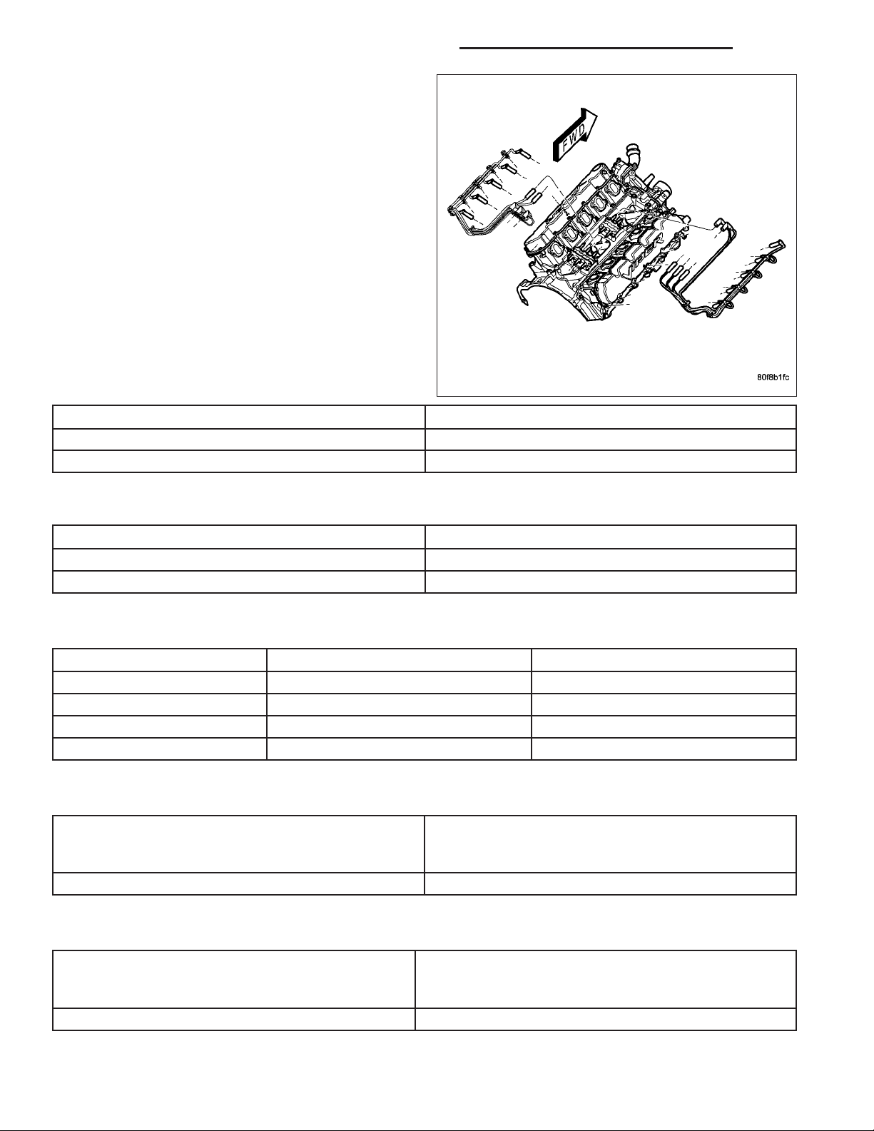
1 - #8 COIL-TO- #5 SPARK PLUG (MARKED 5/8) 7 - CABLE TRAY
2 - #5 COIL-TO- #8 SPARK PLUG (MARKED 5/8) 8 - CLIPS (SPARK PLUG CABLE-TO-TRAY- RETENTION)
3 - #7 COIL-TO- #4 SPARK PLUG (MARKED 4/7) 9 - #2 COIL-TO- #3 SPARK PLUG (MARKED 2/3)
4 - #3 COIL-TO- #2 SPARK PLUG (MARKED 2/3) 10 - #6 COIL-TO- #1 SPARK PLUG (MARKED 1/6)
5 - #1 COIL-TO- #6 SPARK PLUG (MARKED 1/6) 11 - #4 COIL-TO- #7 SPARK PLUG (MARKED 4/7)
6 - CLIPS (TRAY-TO-MANIFOLD RETENTION)
8.3L - SRT-10
Failure to route the cables properly could cause the radio to reproduce ignition noise, cross ignition of the spark
plugs or short circuit the cables to ground.
1. Release the fuel pressure, refer to the Fuel Pressure Release procedure in the Fuel Delivery section.
2. Disconnect the negative battery cable.
3. Remove the air cleaner assembly, refer to the Engine/Air Intake section for more information.
4. Remove the Intake Manifold, refer to the Engine/Manifolds/Intake Manifold for more information.
5. Use the following procedure when removing the high tension cable from the spark plug. Grasp the terminal as
close as possible to the spark plug. Rotate the cover boot 1/2 turn slightly and pull straight up in a steady
motion.Do not use pliers and do not pull the cable at an angle. Doing so will damage the insulation, cable
terminal or the spark plug insulator. Wipe spark plug insulator clean before reinstalling cable.
6. Remove spark plug cable from coil first.
7. Always remove the spark plug cable by grasping the top of the spark plug insulator, turning the boot 1/2 turn and
pulling straight up in a steady motion.
INSTALLATION
INSTALLATION
Install cables into the proper engine cylinder firing order sequence. Refer to Specifications.
When replacing the spark plug and coil cables, route the cables correctly and secure them in the proper retainers.
Failure to route the cables properly may cause the radio to reproduce ignition noise. It could also cause crossignition of the plugs, or, may short-circuit the cables to ground.
When installing new cables, make sure a positive connection is made. A snap should be felt when a good connection is made.
Page 39

DR/DH IGNITION CONTROL - SERVICE INFORMATION 8I - 39
5.7L V-8
Refer to Spark Plug Cable Removal for information.
8.3L - SRT-10
Failure to route the cables properly could cause the
radio to reproduce ignition noise, cross ignition of the
spark plugs or short circuit the cables to ground.
The system uses two epoxy filled coil packs mounted
on engine block post in the valley under the intake
manifold. The rear coil pack, contains 3 separate coils
and fires cylinders 1, 2, 3, 4, 6, and 7. The front coil
pack, contains 2 individual coils and fires cylinders 5,
8, 9, and 10.
NOTE: When replacing the spark plug and coil
cables, route the cables correctly and secure them
in the proper retainers. Failure to route the cables
properly may cause the radio to reproduce ignition
noise. It could also cause cross-ignition of the
plugs, or, may short-circuit the cables to ground.
1. Install wire separator clip on double ended stud on
rear of engine block first. This is the wire separator
clip closest to the ignition coil insulator boots.
2. Connector coil insulator boots over respective ignition coil side post. Take care to match cylinder
number on ignition coil with cylinder number on
ignition cables. Also, make sure to hear the audible
click while making the connection to the coil post.
3. Sequentially install wires into separators clips
mounted on double ended studs mounted on the
outer side of valve cover and and. Start from the
rear and work forward to the front of the engine.
Page 40

8I - 40 IGNITION CONTROL - SERVICE INFORMATION DR/DH
4. After installing all wires into separator clips, install
spark plug insulator boots over respective spark
plugs sequentially from back of engine towards the
front of engine. Make sure to hear the audible click
during installation of spark plug boots.
5. Install Intake Manifold, refer to the Engine/Manifolds/Intake Manifold for more information.
6. Install Air Cleaner Assembly, refer to the Engine/Air
Intake section for more information.
7. Connect the negative battery cable.
8. Use a diagnostic scan tool to pressurize the fuel
system. Check for leaks.
PUSH-BUTTON STARTER SWITCH
DESCRIPTION
A remote push-button switch to engage the starter solenoid is used only on SRT models equipped with a V-10
engine.
Page 41

DR/DH IGNITION CONTROL - SERVICE INFORMATION 8I - 41
REMOVAL
Two screws are used to retain the push-button starter
switch to the back of the instrument panel.
1. Remove plastic panel below push-button switch.
2. Remove electrical connector from back of switch.
3. Remove two switch retaining screws.
4. Remove switch from instrument panel.
INSTALLATION
1. Position switch into instrument panel opening.
2. Install and tighten two switch retaining screws.
3. Install electrical connector to back of switch.
4. Install plastic panel below push-button switch.
Page 42

 Loading...