

Page 1
2021 DODGE DURANGO OWNER’S MANUAL
Page 2

This Owner’s Manual illustrates and describes the operation of features and equipment that are either standard or optional on this vehicle. This manual may also include
a description of features and equipment that are no longer available or were not ordered on this vehicle. Please disregard any features and equipment described in this
manual that are not on this vehicle. FCA US LLC reserves the right to make changes in design and specications, and/or make additions to or improvements to its
products without imposing any obligation upon itself to install them on products previously manufactured.
With respect to any vehicles sold in Canada, the name FCA US LLC shall be deemed to be deleted and the name FCA Canada Inc. used in substitution therefore.
If you are the rst registered retail owner of your vehicle, you may obtain a complimentary printed copy of the Warranty Booklet by calling 1-800-423-6343 (U.S.) or
1-800-387-1143 (Canada) or by contacting your dealer.
This Owner’s Manual is intended to familiarize you with the important features of your vehicle. Your most up-to-date Owner’s Manual, Navigation/Uconnect manuals and
Warranty Booklet can be found by visiting the website on the back cover. U.S. residents can purchase replacement kits by visiting www.techauthority.com and Canadian
residents can purchase replacement kits by calling 1-800-387-1143.
WARNING: Operating, servicing and maintaining a passenger vehicle or off-highway motor vehicle can expose you to
chemicals including engine exhaust, carbon monoxide, phthalates, and lead, which are known to the State of California to
cause cancer and birth defects or other reproductive harm. To minimize exposure, avoid breathing exhaust, do not idle the
engine except as necessary, service your vehicle in a well-ventilated area and wear gloves or wash your hands frequently
when servicing your vehicle. For more information go to www.P65Warnings.ca.gov/passenger-vehicle.
Page 3

TABLE OF CONTENTS
1 INTRODUCTION.............................................................................................................................. 8
2 GETTING TO KNOW YOUR VEHICLE ................................................................................. 14
3 GETTING TO KNOW YOUR INSTRUMENT PANEL ........................................................87
4 STARTING AND OPERATING ...............................................................................................109
5 MULTIMEDIA ............................................................................................................................... 175
6 SAFETY ........................................................................................................................................206
7 IN CASE OF EMERGENCY ....................................................................................................266
8 SERVICING AND MAINTENANCE ......................................................................................289
9 TECHNICAL SPECIFICATIONS ............................................................................................346
10 CUSTOMER ASSISTANCE ..................................................................................................... 353
11 INDEX .............................................................................................................................................358
1
2
3
4
5
6
7
8
9
10
11
Page 4

2
INTRODUCTION
Symbols Key..............................................................9
ROLLOVER WARNING .............................................9
VEHICLE MODIFICATIONS/ALTERATIONS.......... 10
Symbol Glossary.................................................... 10
GETTING TO KNOW YOUR VEHICLE
KEYS ....................................................................... 14
Key Fob .............................................................14
SENTRY KEY .......................................................... 17
IGNITION SWITCH .................................................. 17
Keyless Enter ‘n Go Ignition.............................17
REMOTE START — IF EQUIPPED .......................... 19
How To Use Remote Start................................19
To Exit Remote Start Mode..............................20
Remote Start Front Defrost Activation —
If Equipped........................................................20
Remote Start Comfort Systems —
If Equipped........................................................21
Remote Start Windshield Wiper De–Icer
Activation — If Equipped ..................................21
Remote Start Cancel Message —
If Equipped........................................................21
VEHICLE SECURITY SYSTEM — IF EQUIPPED .....22
To Arm The System ..........................................22
To Disarm The System.....................................22
Rearming Of The System .................................23
Security System Manual Override...................23
Tamper Alert .....................................................23
DOORS ....................................................................23
Manual Door Locks ..........................................23
Power Door Locks ............................................24
Keyless Enter ‘n Go — Passive Entry ..............24
Automatic Unlock On Exit Feature —
If Equipped........................................................27
Automatic Door Locks —
If Equipped........................................................27
Child-Protection Door Lock System —
Rear Doors .......................................................27
STEERING WHEEL ..................................................27
Manual Tilt/Telescoping Steering Column —
If Equipped .......................................................27
Power Tilt/Telescoping Steering Column —
If Equipped .......................................................28
Heated Steering Wheel — If Equipped ...........28
DRIVER MEMORY SETTINGS — IF EQUIPPED.....29
Programming The Memory Feature ................30
Linking And Unlinking The Remote Keyless
Entry Key Fob To Memory................................30
Memory Position Recall ...................................30
SEATS...................................................................... 31
Manual Adjustment (Front Seats) —
If Equipped .......................................................31
Manual Adjustment (Rear Seats)....................33
Power Adjustment (Front Seats) —
If Equipped ......................................................37
Power Passenger Seat Adjustment —
If Equipped .......................................................38
Heated Seats — If Equipped ...........................39
Front Ventilated Seats — If Equipped .............40
Head Restraints ...............................................41
UCONNECT VOICE RECOGNITION ....................... 43
Introducing Voice Recognition ........................43
Basic Voice Commands ...................................44
Get Started .......................................................44
Additional Information .....................................44
MIRRORS ............................................................... 45
Inside Rearview Mirror.....................................45
Illuminated Vanity Mirrors ..............................45
Outside Mirrors ................................................46
Outside Automatic Dimming Mirrors —
If Equipped .......................................................46
Power Mirrors ..................................................46
Heated Mirrors — If Equipped .........................47
Tilt Side Mirrors In Reverse —
If Equipped .......................................................47
Page 5

3
UNIVERSAL GARAGE DOOR OPENER
(HOMELINK®) .......................................................47
Before You Begin Programming HomeLink® ... 47
Erasing All The HomeLink® Channels ............48
Identifying Whether You Have A Rolling Code
Or Non-Rolling Code Device.............................48
Programming HomeLink® To A Garage
Door Opener .....................................................48
Programming HomeLink® To A
Miscellaneous Device ......................................49
Reprogramming A Single HomeLink® Button..49
Canadian/Gate Operator Programming .........50
EXTERIOR LIGHTS.................................................. 51
Multifunction Lever ..........................................51
Headlight Switch ..............................................51
Daytime Running Lights (DRLs) ......................52
High/Low Beam Switch....................................52
Automatic High Beam — If Equipped ..............52
Flash-To-Pass....................................................52
Automatic Headlights ......................................52
Parking Lights And Panel Lights......................53
Automatic Headlights With Wipers..................53
Headlight Delay ................................................53
Lights-On Reminder..........................................53
Fog Lights — If Equipped..................................53
Turn Signals......................................................54
Lane Change Assist — If Equipped..................54
Automatic Headlight Leveling —
If Equipped........................................................54
Battery Saver ....................................................54
INTERIOR LIGHTS ..................................................54
Courtesy Lights.................................................54
WINDSHIELD WIPERS AND WASHERS...............56
Windshield Wiper Operation ...........................56
Rain Sensing Wipers — If Equipped ...............57
Rear Window Wiper/Washer ...........................58
CLIMATE CONTROLS..............................................59
Automatic Climate Control Descriptions
And Functions...................................................59
Automatic Temperature Control (ATC)............65
Climate Voice Recognition...............................66
Operating Tips .................................................66
INTERIOR STORAGE AND EQUIPMENT ...............68
Storage..............................................................68
USB/AUX Control .............................................71
Electrical Power Outlets...................................72
Power Inverter — If Equipped ..........................74
Wireless Charging Pad —
If Equipped .......................................................75
WINDOWS ..............................................................76
Power Windows ................................................76
Wind Buffeting .................................................77
POWER SUNROOF — IF EQUIPPED......................77
Opening And Closing The Sunroof...................78
Sunshade Operation ........................................78
Pinch Protect Feature ......................................78
Venting Sunroof................................................79
Sunroof Maintenance ......................................79
Ignition Off Operation.......................................79
HOOD....................................................................... 79
Opening The Hood ...........................................79
Closing The Hood .............................................79
LIFTGATE................................................................. 80
Power Liftgate — If Equipped...........................80
Cargo Area Features ....................................... 81
ROOF LUGGAGE RACK — IF EQUIPPED .............. 82
Deploying The Crossbars.................................83
Stowing The Crossbars ....................................84
GETTING TO KNOW YOUR
INSTRUMENT PANEL
INSTRUMENT CLUSTER ........................................ 87
Instrument Cluster Descriptions .....................88
INSTRUMENT CLUSTER DISPLAY........................ 89
Location And Controls......................................89
Engine Oil Life Reset .......................................91
Display And Messages.....................................92
Instrument Cluster Display Menu Items ........ 93
Battery Saver On/Battery Saver Mode
Message — Electrical Load Reduction
Actions — If Equipped .....................................96
WARNING LIGHTS AND MESSAGES ...................98
Red Warning Lights..........................................98
Yellow Warning Lights................................... 101
Yellow Indicator Lights.................................. 104
Green Indicator Lights .................................. 105
White Indicator Lights................................... 106
Blue Indicator Lights..................................... 106
Page 6

4
ONBOARD DIAGNOSTIC SYSTEM — OBD II .....106
Onboard Diagnostic System
(OBD II) Cybersecurity ................................... 107
EMISSIONS INSPECTION AND MAINTENANCE
PROGRAMS .........................................................107
STARTING AND OPERATING
STARTING THE ENGINE.......................................109
Automatic Transmission ............................... 109
Normal Starting ............................................ 109
AutoPark ........................................................ 110
If Engine Fails To Start .................................. 112
Cold Weather Operation
(Below –22°F Or −30°C) ............................ 112
After Starting.................................................. 112
ENGINE BLOCK HEATER — IF EQUIPPED .........112
ENGINE BREAK-IN RECOMMENDATIONS ........113
PARKING BRAKE ................................................113
AUTOMATIC TRANSMISSION..............................115
Ignition Park Interlock................................... 116
Brake Transmission Shift Interlock
(BTSI) System ................................................ 116
Fuel Economy (ECO) Mode ...........................116
Eight-Speed Automatic Transmission .......... 117
SPORT MODE — IF EQUIPPED............................122
ALL-WHEEL DRIVE OPERATION ........................ 122
Single-Speed Operating Instructions/
Precautions — If Equipped............................ 122
Electronically Shifted Transfer Case
(Two-Position Switch) — If Equipped ............ 122
Shifting Procedure ........................................ 124
TOW N GO — IF EQUIPPED................................. 125
Guidelines For Track Use.............................. 126
FUEL SAVER TECHNOLOGY 5.7L ONLY —
IF EQUIPPED ........................................................ 127
POWER STEERING .............................................. 127
STOP/START SYSTEM — IF EQUIPPED............. 128
Autostop Mode .............................................. 128
Possible Reasons The Engine Does
Not Autostop.................................................. 128
To Start The Engine While In Autostop
Mode .............................................................. 129
To Manually Turn Off The
Stop/Start System......................................... 129
To Manually Turn On The
Stop/Start System......................................... 130
System Malfunction ...................................... 130
CRUISE CONTROL SYSTEMS — IF EQUIPPED .... 130
Cruise Control — If Equipped ....................... 130
Adaptive Cruise Control (ACC) —
If Equipped ................................................... 132
PARKSENSE FRONT/REAR PARK ASSIST
SYSTEM — IF EQUIPPED ....................................143
ParkSense Sensors....................................... 144
ParkSense Display ........................................ 144
ParkSense Warning Display ......................... 147
Enabling And Disabling ParkSense.............. 147
Operation With A Trailer................................ 147
Service The ParkSense Park Assist System ...148
Cleaning The ParkSense System ................. 148
ParkSense System Usage Precautions........ 148
LANESENSE — IF EQUIPPED .............................149
LaneSense Operation ................................... 149
Turning LaneSense On Or Off....................... 150
LaneSense Warning Message...................... 150
Changing LaneSense Status ........................ 152
PARKVIEW REAR BACK UP CAMERA ..............152
REFUELING THE VEHICLE ................................... 154
VEHICLE LOADING ..............................................154
Certification Label......................................... 154
Page 7

5
TRAILER TOWING ................................................155
Common Towing Definitions......................... 156
Trailer Hitch Classification............................ 158
Trailer Towing Weights
(Maximum Trailer Weight Ratings) .............. 159
Trailer Hitch Receiver Cover Removal —
If Equipped..................................................... 160
Trailer And Tongue Weight ........................... 160
Towing Requirements .................................. 161
Towing Tips ................................................... 166
RECREATIONAL TOWING
(BEHIND MOTORHOME) .....................................167
Towing This Vehicle Behind
Another Vehicle .............................................167
Recreational Towing — Rear-Wheel
Drive Models.................................................. 168
Recreational Towing —
All Wheel Drive Models
(Single-Speed Transfer Case)....................... 168
Recreational Towing —
All-Wheel Drive Models (Two-Speed
Transfer Case) ............................................... 168
DRIVING TIPS ....................................................... 171
On-Road Driving Tips..................................... 171
Off-Road Driving Tips..................................... 172
MULTIMEDIA
UCONNECT SYSTEMS ........................................175
CYBERSECURITY ................................................ 175
UCONNECT SETTINGS......................................... 176
Customer Programmable Features.............. 177
STEERING WHEEL AUDIO CONTROLS.............. 194
Radio Operation ............................................ 194
Media Mode................................................... 194
UCONNECT REAR SEAT ENTERTAINMENT
(RSE) SYSTEM — IF EQUIPPED .......................... 194
Getting Started .............................................. 194
Dual Video Screen......................................... 196
Play A Blu-ray™ Disc...................................... 196
Play Video Games ......................................... 198
Important Notes For Dual Video
Screen System .............................................. 199
Blu-ray™ Disc Player Remote Control .......... 199
Headphones Operation................................. 200
Controls.......................................................... 200
Replacing The Headphone Batteries........... 201
Accessibility — If Equipped ........................... 201
Stereo Headphone Lifetime
Limited Warranty........................................... 201
RADIO OPERATION AND MOBILE PHONES..... 205
Regulatory And Safety Information .............. 205
SAFETY
SAFETY FEATURES ..............................................206
Anti-Lock Brake System (ABS) ..................... 206
Electronic Brake Control (EBC) System ...... 207
AUXILIARY DRIVING SYSTEMS ..........................212
Blind Spot Monitoring (BSM) —
If Equipped .................................................... 212
Forward Collision Warning (FCW)
With Mitigation .............................................. 217
Tire Pressure Monitoring System (TPMS).... 219
OCCUPANT RESTRAINT SYSTEMS ...................223
Occupant Restraint Systems Features........ 223
Important Safety Precautions ...................... 223
Seat Belt Systems ........................................ 224
Supplemental Restraint Systems (SRS) ...... 231
Child Restraints............................................. 245
SAFETY TIPS ........................................................263
Transporting Passengers.............................. 263
Transporting Pets ......................................... 263
Safety Checks You Should Make Inside
The Vehicle ................................................... 263
Periodic Safety Checks You Should Make
Outside The Vehicle ...................................... 264
Exhaust Gas................................................... 265
Carbon Monoxide Warnings ......................... 265
Page 8

6
IN CASE OF EMERGENCY
HAZARD WARNING FLASHERS ........................266
ASSIST AND SOS MIRROR — IF EQUIPPED......266
JACKING AND TIRE CHANGING ........................270
Preparations For Jacking .............................. 271
Jack Location................................................. 271
Spare Tire Stowage ....................................... 272
Spare Tire Removal....................................... 272
Jacking Instructions .....................................274
JUMP STARTING ..................................................278
Preparations For Jump Start......................... 279
Jump Starting Procedure .............................. 280
REFUELING IN EMERGENCY – IF EQUIPPED ..281
IF YOUR ENGINE OVERHEATS ...........................282
MANUAL PARK RELEASE ...................................283
FREEING A STUCK VEHICLE .............................. 285
TOWING A DISABLED VEHICLE ........................ 286
Rear Wheel Drive Models ............................. 287
All Wheel Drive Models ................................. 288
ENHANCED ACCIDENT RESPONSE
SYSTEM (EARS) .................................................. 288
EVENT DATA RECORDER (EDR) ........................288
SERVICING AND MAINTENANCE
SCHEDULED SERVICING ................................... 289
Maintenance Plan ......................................... 290
ENGINE COMPARTMENT.................................... 293
3.6L Engine ................................................... 293
5.7L Engine ................................................... 294
Checking Oil Level......................................... 295
Adding Washer Fluid .................................... 295
Maintenance-Free Battery ........................... 295
Pressure Washing ......................................... 296
VEHICLE MAINTENANCE.....................................296
Engine Oil ...................................................... 296
Engine Oil Filter ............................................. 297
Engine Air Cleaner Filter .............................. 297
Air Conditioner Maintenance ....................... 298
Accessory Drive Belt Inspection................... 301
Body Lubrication ........................................... 302
Windshield Wiper Blades.............................. 302
Exhaust System ............................................ 305
Cooling System.............................................. 306
Brake System ............................................... 309
Automatic Transmission ............................... 310
Front/Rear Axle Fluid ................................... 311
Transfer Case ............................................... 311
Fuses.............................................................. 312
Bulb Replacement ........................................ 320
Page 9

7
TIRES .....................................................................322
Tire Safety Information ................................322
Tires — General Information ........................ 330
Tire Types....................................................... 335
Spare Tires — If Equipped............................. 336
Wheel And Wheel Trim Care ........................ 338
Snow Traction Devices.................................. 339
Tire Rotation Recommendations ................ 341
DEPARTMENT OF TRANSPORTATION UNIFORM
TIRE QUALITY GRADES ......................................342
Treadwear...................................................... 342
Traction Grades............................................. 342
Temperature Grades..................................... 342
STORING THE VEHICLE ......................................343
BODYWORK..........................................................343
Protection From Atmospheric Agents ..........343
Body And Underbody Maintenance.............. 343
Preserving The Bodywork ............................. 343
INTERIORS ...........................................................344
Seats And Fabric Parts.................................. 344
Plastic And Coated Parts .............................. 345
Leather Surfaces........................................... 345
Glass Surfaces .............................................. 345
TECHNICAL SPECIFICATIONS
VEHICLE IDENTIFICATION NUMBER (VIN)........ 346
BRAKE SYSTEM................................................... 346
WHEEL AND TIRE TORQUE SPECIFICATIONS.. 346
Torque Specifications ................................... 346
FUEL REQUIREMENTS ....................................... 347
3.6L Engine .................................................. 347
5.7L Engine ................................................... 347
Reformulated Gasoline ................................ 348
Materials Added To Fuel............................... 348
Gasoline/Oxygenate Blends......................... 348
Do Not Use E-85 In Non-Flex Fuel Vehicles....348
CNG And LP Fuel System Modifications ...... 349
Methylcyclopentadienyl Manganese
Tricarbonyl (MMT) In Gasoline...................... 349
Fuel System Cautions ................................... 349
FLUID CAPACITIES .............................................. 350
ENGINE FLUIDS AND LUBRICANTS .................. 351
CHASSIS FLUIDS AND LUBRICANTS ............... 352
CUSTOMER ASSISTANCE
SUGGESTIONS FOR OBTAINING SERVICE FOR
YOUR VEHICLE ....................................................353
Prepare For The Appointment ...................... 353
Prepare A List ................................................ 353
Be Reasonable With Requests..................... 353
IF YOU NEED ASSISTANCE ................................ 353
FCA US LLC Customer Center....................... 354
FCA Canada Inc. Customer Center .............. 354
Mexico............................................................ 354
Puerto Rico And US Virgin Islands ............... 354
Customer Assistance For The Hearing Or
Speech Impaired (TDD/TTY)......................... 354
Service Contract ........................................... 354
WARRANTY INFORMATION................................ 355
MOPAR® PARTS .................................................355
REPORTING SAFETY DEFECTS ..........................355
In The 50 United States And
Washington, D.C............................................ 355
In Canada ...................................................... 356
PUBLICATION ORDER FORMS ..........................356
General Information............................................357
Page 10

8
INTRODUCTION
Dear Customer,
Congratulations on the purchase of your new Dodge vehicle. Be assured that it represents precision workmanship, distinctive styling, and high quality.
This is a specialized utility vehicle. It can go places and perform tasks that are not intended for conventional passenger vehicles. It handles and
maneuvers differently from many passenger vehicles both on-road and off-road, so take time to become familiar with your vehicle. If equipped, the
two-wheel drive version of this vehicle was designed for on-road use only. It is not intended for off-road driving or use in other severe conditions suited
for a four-wheel drive vehicle. Before you start to drive this vehicle, read the Owner’s Manual. Be sure you are familiar with all vehicle controls,
particularly those used for braking, steering, transmission, and transfer case shifting. Learn how your vehicle handles on different road surfaces. Your
driving skills will improve with experience. When driving off-road, or working the vehicle, don’t overload the vehicle or expect the vehicle to overcome
the natural laws of physics. Always observe federal, state, provincial and local laws wherever you drive. As with other vehicles of this type, failure to
operate this vehicle correctly may result in loss of control or a collision Ú page 171.
This Owner's Manual has been prepared with the assistance of service and engineering specialists to acquaint you with the operation and maintenance
of your vehicle. It is supplemented by customer-oriented documents. Within this information, you will find a description of the services that FCA US LLC
offers to its customers as well as the details of the terms and conditions for maintaining its validity. Please take the time to read all of these publications
carefully before driving your vehicle for the first time. Following the instructions, recommendations, tips, and important warnings in this manual will help
ensure safe and enjoyable operation of your vehicle.
This Owner's Manual describes all versions of this vehicle. Options and equipment dedicated to specific markets or versions are not expressly indicated
in the text. Therefore, you should only consider the information that is related to the trim level, engine, and version that you have purchased. Any content
introduced throughout the Owner's Information, which may or may not be applicable to your vehicle, will be identified with the wording "If Equipped". All
data contained in this publication are intended to help you use your vehicle in the best possible way. FCA US LLC aims at a constant improvement of
the vehicles produced. For this reason, it reserves the right to make changes to the model described for technical and/or commercial reasons. For
further information, contact an authorized dealer.
When it comes to service, remember that authorized dealers know your Dodge best, have factory-trained technicians, genuine Mopar® parts, and care
about your satisfaction.
Page 11
9
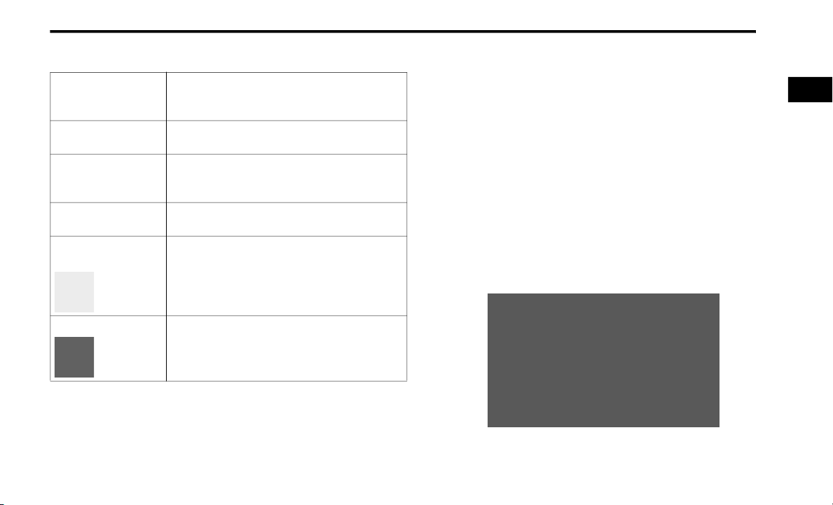
SYMBOLS KEY
WARNING!
CAUTION!
NOTE:
TIP:
PAGE REFERENCE
ARROW
FOOTNOTE
These statements are against operating
procedures that could result in a collision,
bodily injury and/or death.
These statements are against procedures that
could result in damage to your vehicle.
A suggestion which will improve installation,
operation, and reliability. If not followed, may
result in damage.
General ideas/solutions/suggestions on easier
use of the product or functionality.
Follow this reference for additional information
on a particular feature.
Supplementary and relevant information
pertaining to the topic.
If you do not read this entire Owner’s Manual, you may miss important
information. Observe all Cautions and Warnings.
ROLLOVER WARNING
Utility vehicles have a significantly higher rollover rate than other types
of vehicles. This vehicle has a higher ground clearance and a higher
center of gravity than many passenger vehicles. It is capable of
performing better in a wide variety of off-road applications. Driven in an
unsafe manner, all vehicles can go out of control. Because of the higher
center of gravity, if this vehicle is out of control, it may roll over while
some other vehicles may not.
Do not attempt sharp turns, abrupt maneuvers, or other unsafe driving
actions that can cause loss of vehicle control. Failure to operate this
vehicle safely may result in a collision, rollover of the vehicle, and severe
or fatal injury. Drive carefully.
Rollover Warning Label
1
Page 12
10
Failure to use the driver and passenger seat belts provided is a major
cause of severe or fatal injury. In fact, the US government notes that the
universal use of existing seat belts could cut the highway death toll by
10,000 or more each year and could reduce disabling injuries by two
million annually. In a rollover crash, an unbelted person is significantly
more likely to die than a person wearing a seat belt. Always buckle up.
VEHICLE MODIFICATIONS/ALTERATIONS
WARNING!
Any modifications or alterations to this vehicle could seriously affect its
roadworthiness and safety and may lead to a collision resulting in
serious injury or death.
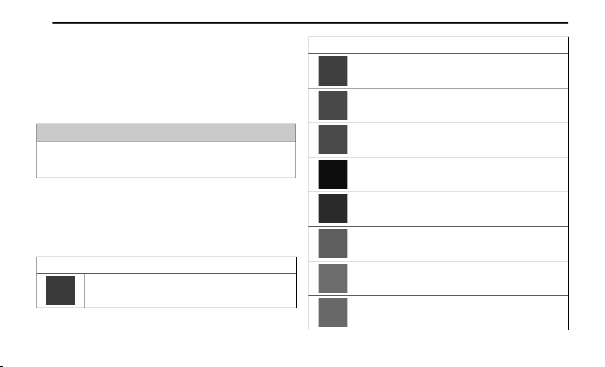
SYMBOL GLOSSARY
Some car components have colored labels with symbols indicating
precautions to be observed when using this component. It is important to
follow all warnings when operating your vehicle. See below for the
definition of each symbol Ú page 98.
Red Warning Lights
Seat Belt Reminder Warning Light
Ú page 98
Red Warning Lights
Air Bag Warning Light
Ú page 98
Brake Warning Light
Ú page 98
Battery Charge Warning Light
Ú page 99
Door Open Warning Light — If Equipped
Ú page 99
Electric Power Steering (EPS) Fault Warning Light
Ú page 99
Electronic Throttle Control (ETC) Warning Light
Ú page 99
Engine Coolant Temperature Warning Light
Ú page 100
Hood Open Warning Light
Ú page 100
Page 13
11
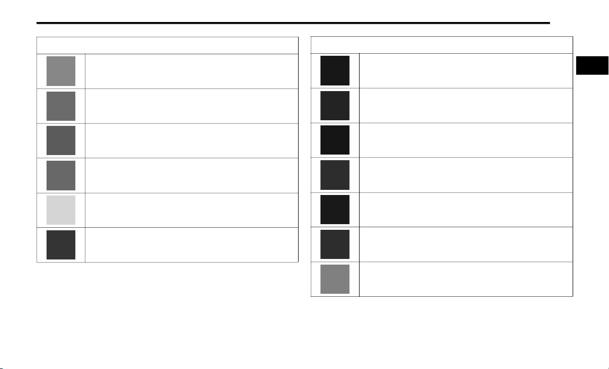
Red Warning Lights
Liftgate Open Warning Light
Ú page 100
Oil Pressure Warning Light
Ú page 100
Oil Temperature Warning Light
Ú page 100
Trailer Brake Disconnected Warning Light
Ú page 100
Transmission Temperature Warning Light — If Equipped
Ú page 101
Vehicle Security Warning Light — If Equipped
Ú page 101
Yellow Warning Lights
Engine Check/Malfunction Indicator Warning Light (MIL)
Ú page 101
Electronic Stability Control (ESC) Active Warning Light
Ú page 102
Electronic Stability Control (ESC) OFF Warning Light
Ú page 102
Low Washer Fluid Warning Light — If Equipped
Ú page 102
Tire Pressure Monitoring System (TPMS) Warning Light
Ú page 102
Low Fuel Warning Light
Ú page 103
Anti-Lock Brake System (ABS) Warning Light
Ú page 104
1
Page 14
12
Yellow Warning Lights
Service Forward Collision Warning (FCW) Light —
If Equipped
Ú page 104
Service Adaptive Cruise Control (ACC) Warning Light —
If Equipped
Ú page 104
Service AWD Warning Light — If Equipped
Ú page 104
Service Stop/Start System Warning Light — If Equipped
Ú page 104
LaneSense Warning Light — If Equipped
Ú page 104
Service LaneSense Warning Light — If Equipped
Ú page 104
Cruise Control Fault Warning Light — If Equipped
Ú page 104
Yellow Indicator Lights
Forward Collision Warning (FCW) OFF Indicator Light —
If Equipped
Ú page 104
All Wheel Drive (AWD) Low Indicator Light — If Equipped
Ú page 104
NEUTRAL Indicator Light — If Equipped
Ú page 105
Green Indicator Lights
Adaptive Cruise Control (ACC) Set With Target Light —
If Equipped
Ú page 105
Adaptive Cruise Control (ACC) Set Without Target Light —
If Equipped
Ú page 105
Cruise Control Set Indicator Light — If Equipped
Ú page 105
Page 15
13
Green Indicator Lights
Front Fog Indicator Light — If Equipped
Ú page 105
LaneSense Indicator Light — If Equipped
Ú page 106
Park/Headlight On Indicator Light
Ú page 105
Snow Mode Indicator Light — If Equipped
Ú page 105
Sport Mode Indicator Light
Ú page 105
Stop/Start Active Indicator Light — If Equipped
Ú page 105
Tow Mode Indicator Light — If Equipped
Ú page 105
Green Indicator Lights
Turn Signal Indicator Lights
Ú page 106
White Indicator Lights
Adaptive Cruise Control (ACC) Ready Light — If Equipped
Ú page 106
Cruise Control Ready Indicator Light
Ú page 106
LaneSense Indicator Light —
If Equipped
Ú page 106
Blue Indicator Lights
High Beam Indicator Light
Ú page 106
1
Page 16

14
GETTING TO KNOW YOUR VEHICLE
KEYS
KEY FOB
Your vehicle is equipped with a key fob which
supports Passive Entry, Remote Keyless Entry
(RKE), Keyless Enter ‘n Go (if equipped),
Remote Start (if equipped), and remote power
liftgate operation. The key fob allows you to lock
or unlock the doors and liftgate from distances
up to approximately 66 ft (20 m). The key fob
does not need to be pointed at the vehicle to
activate the system. The key fob also contains
an emergency key, which is stored in the rear of
the key fob.
NOTE:
The key fob’s wireless signal may be blocked
if the key fob is located next to a mobile
phone, laptop, or other electronic device.
This may result in poor performance.
With ignition in the ON position and the
vehicle moving at 2 mph (4 km/h), all RKE
commands are disabled.
Key Fob
1 — Unlock
2 — Liftgate
3 — Emergency Key
4 — Lock
5 — Remote Start
6 — PANIC
In case the ignition switch does not change with
the push of a button, the key fob may have a low
or fully depleted battery. A low key fob battery
can be verified by referring to the instrument
cluster, which will display directions to follow
Ú page 357.
To Lock/Unlock The Doors And Liftgate
Push and release the unlock button on the key
fob once to unlock the driver’s door, or twice
within five seconds to unlock all the doors and
the liftgate. To lock all the doors and the liftgate,
push the lock button once.
When the doors are unlocked, the turn signals
will flash and the illuminated entry system will
be activated. When the doors are locked, the
turn signals will flash and the horn will chirp.
Page 17

GETTING TO KNOW YOUR VEHICLE 15
NOTE:
If the vehicle is unlocked with the key fob,
and no door is opened within 60 seconds, the
vehicle will re-lock and the security system
will arm (if equipped).
If one or more doors are open, or the liftgate
is open, the doors will lock. The doors will
unlock again automatically if the key is left
inside the passenger compartment, otherwise the doors will stay locked.
All doors can be programmed to unlock on the
first push of the unlock button within Uconnect
Settings Ú page 176.
Replacing The Battery In The Key Fob
The recommended replacement battery is one
CR2032 battery.
NOTE:
Customers are recommended to use a
battery obtained from Mopar®. Aftermarket
coin battery dimensions may not meet the
original OEM coin battery dimensions.
Perchlorate Material — special handling may
apply. See
ouswaste/perchlorate
www.dtsc.ca.gov/hazard-
for further information.
Do not touch the battery terminals that are
on the back housing or the printed circuit
board.
1. Remove the emergency key (2) by sliding
the emergency key release (1) on the back
of the key fob and pulling the emergency
key out with your other hand.
Emergency Key Removal
1 — Emergency Key Release
2 — Emergency Key
2. Separate the key fob halves using a #2 flat
blade screwdriver or a coin, and gently pry
the two halves of the key fob apart. Make
sure not to damage the seal during removal.
2
Emergency Key Removal
Separating Case With A Coin
Page 18
16 GETTING TO KNOW YOUR VEHICLE
Key Fob Battery Replacement
3. Remove the back cover to access and
replace the battery. When replacing the
battery, match the (+) sign on the battery to
the (+) sign on the inside of the battery clip,
located on the back cover. Avoid touching
the new battery with your fingers. Skin oils
may cause battery deterioration. If you
touch a battery, clean it with rubbing
alcohol.
4. To assemble the key fob case, snap the two
halves together.
WARNING!
The integrated key fob contains a coin cell
battery. Do not ingest the battery; there is a
chemical burn hazard. If the coin cell
battery is swallowed, it can cause severe
internal burns in just two hours and can
lead to death.
If you think a battery may have been swal-
lowed or placed inside any part of the body,
seek immediate medical attention.
Keep new and used batteries away from
children. If the battery compartment does
not close securely, stop using the product
and keep it away from children.
Programming And Requesting Additional Key Fobs
Programming the key fob may be performed by
an authorized dealer.
NOTE:
Once a key fob is programmed to a vehicle, it
cannot be re-purposed and reprogrammed to
another vehicle.
Only key fobs that are programmed to the
vehicle electronics can be used to start and
operate the vehicle.
WARNING!
Always remove the key fobs from the
vehicle and lock all doors when leaving the
vehicle unattended.
For vehicles equipped with Keyless Enter
‘n Go Ignition, always remember to place
the ignition in the OFF position.
Duplication of key fobs may be performed at an
authorized dealer. This procedure consists of
programming a blank key fob to the vehicle
electronics.
NOTE:
When having the Sentry Key Immobilizer
system serviced, bring all vehicle keys with
you to an authorized dealer.
Keys must be ordered to the correct key cut
to match the vehicle locks.
Page 19
GETTING TO KNOW YOUR VEHICLE 17
SENTRY KEY
The Sentry Key Immobilizer system prevents
unauthorized vehicle operation by disabling the
engine. The system does not need to be armed
or activated. Operation is automatic, regardless
of whether the vehicle is locked or unlocked.
The system uses a key fob, keyless push button
ignition and a Radio Frequency (RF) receiver to
prevent unauthorized vehicle operation.
Therefore, only key fobs that are programmed
to the vehicle can be used to start and operate
the vehicle. The system will shut the engine off
in two seconds if an incorrect key fob is used to
start the engine.
After placing the ignition in the ON/RUN
position, the Vehicle Security Light will turn on
for three seconds for a bulb check. If the light
remains on after the bulb check, it indicates
that there is a problem with the electronics. In
addition, if the light begins to flash after the
bulb check, it indicates that someone used an
invalid key fob to start the engine. Either of
these conditions will result in the engine being
shut off after two seconds.
If the Vehicle Security Light turns on during
normal vehicle operation (vehicle running for
longer than 10 seconds), it indicates that there
is a fault in the electronics. Should this occur,
have the vehicle serviced as soon as possible by
an authorized dealer.
CAUTION!
The Sentry Key Immobilizer system is not
compatible with some aftermarket remote
starting systems. Use of these systems may
result in vehicle starting problems and loss of
security protection.
All of the key fobs provided with your new
vehicle have been programmed to the vehicle
electronics Ú page 357.
IGNITION SWITCH
KEYLESS ENTER ‘N GO IGNITION
This feature allows the driver to operate the
ignition switch with the push of a button as long
as the key fob is in the passenger compartment.
The START/STOP ignition button has several
operating modes that are labeled and will
illuminate when in position. These modes are
OFF, ACC, ON/RUN, and START.
2
START/STOP Ignition Button
1 — OFF
2 — ACC
3 — ON/RUN
The push button ignition can be placed in the
following modes:
OFF
The engine is stopped
Some electrical devices (e.g. power locks,
alarm, etc.) are still available
Page 20
18 GETTING TO KNOW YOUR VEHICLE
ACC
Engine is not started
Some electrical devices are available (e.g.
power windows)
ON/RUN
Driving position
All the electrical devices are available (e.g.
climate controls, etc.)
START
The engine will start (when foot is on the
brake pedal)
NOTE:
If the ignition position does not change with a
push of the ignition button, and the instrument
cluster display message “Key Fob Not
Detected” is being displayed, the key fob may
have a low or depleted battery. In this situation,
a back up method can be used to operate the
ignition switch. Put the nose side of the key fob
(side opposite of the emergency key) against
the START/STOP ignition button and push to
operate the ignition switch.
Depleted Key Fob Battery Procedure
WARNING!
Before exiting a vehicle, always shift the
automatic transmission into PARK and
apply the parking brake. Always make sure
the keyless ignition is in the OFF position,
remove the key fob from the vehicle and
lock the vehicle.
Never leave children alone in a vehicle, or
with access to an unlocked vehicle.
(Continued)
WARNING! (Continued)
Allowing children to be in a vehicle unat-
tended is dangerous for a number of
reasons. A child or others could be seriously
or fatally injured. Children should be
warned not to touch the parking brake,
brake pedal or the gear selector.
Do not leave the key fob in or near the
vehicle, or in a location accessible to children, and do not leave the ignition of a
vehicle equipped with Keyless Enter ‘n Go
in the ACC or ON/RUN position. A child
could operate power windows, other
controls, or move the vehicle.
Do not leave children or animals inside
parked vehicles in hot weather. Interior heat
build-up may cause serious injury or death.
CAUTION!
An unlocked vehicle is an invitation. Always
remove the key fobs from vehicle, place the
ignition in the OFF position and lock all doors
when leaving the vehicle unattended.
Page 21
GETTING TO KNOW YOUR VEHICLE 19
NOTE:
For more information on normal starting
procedures, see Ú page 109.
When opening the driver's door with the igni-
tion in ON/RUN (engine not running), a chime
will sound to remind you to place the ignition
in the OFF position. In addition to the chime,
the message will display “Ignition Or Accessory On” in the cluster.
REMOTE START — IF EQUIPPED
This system uses the key fob to start
the engine conveniently from outside
the vehicle while still maintaining
security. The system has a range of
328 ft (100 m).
Remote Start is used to defrost windows in cold
weather, and to reach a comfortable climate in
all ambient conditions before the driver enters
the vehicle.
NOTE:
Obstructions between the vehicle and key fob
may reduce this range Ú page 357.
WARNING!
Do not start or run an engine in a closed
garage or confined area. Exhaust gas
contains Carbon Monoxide (CO) which is
odorless and colorless. Carbon Monoxide is
poisonous and can cause serious injury or
death when inhaled.
Keep key fobs away from children. Opera-
tion of the Remote Start system, windows,
door locks or other controls could cause
serious injury or death.
HOW TO USE REMOTE START
Push and release the Remote Start button on
the key fob twice within five seconds. The
vehicle doors will lock, the parking lights will
flash, and the horn will chirp twice (if
programmed). Then, the engine will start, and
the vehicle will remain in the Remote Start
mode for a 15 minute cycle. Pushing the
Remote Start button a third time shuts the
engine off.
To drive the vehicle, push the unlock button,
and with a valid Keyless Enter ‘n Go key fob in
the vehicle, place the ignition in the ON/RUN
position.
NOTE:
With Remote Start, the engine will only run
for 15 minutes.
Remote Start can only be used twice.
If an engine fault is present or fuel level is
low, the vehicle will start and then shut down
in 10 seconds.
The park lamps will turn on and remain on
during Remote Start mode.
For security, power window operation is
disabled when the vehicle is in the Remote
Start mode.
The ignition must be placed in the ON/RUN
position before the Remote Start sequence
can be repeated for a third cycle.
All of the following conditions must be met
before the engine will remote start:
Gear selector in PARK
Doors closed
Hood closed
Liftgate closed
Hazard switch off
2
Page 22
20 GETTING TO KNOW YOUR VEHICLE
Brake switch inactive (brake pedal not
pressed)
Battery at an acceptable charge level
PANIC button not pushed
System not disabled from previous remote
start event
Vehicle Security system indicator flashing
Ignition in OFF position
Fuel level meets minimum requirement
Vehicle Security system is not signaling an
intrusion
Malfunction Indicator Light (MIL) is not illumi-
nated
WARNING!
Do not start or run an engine in a closed
garage or confined area. Exhaust gas
contains Carbon Monoxide (CO) which is
odorless and colorless. Carbon Monoxide is
poisonous and can cause serious injury or
death when inhaled.
(Continued)
WARNING! (Continued)
Keep key fobs away from children. Opera-
tion of the Remote Start system, windows,
door locks or other controls could cause
serious injury or death.
TO EXIT REMOTE START MODE
To drive the vehicle after starting the Remote
Start system, either push and release the
unlock button on the key fob to unlock the
doors, or unlock the vehicle using Keyless
Enter ‘n Go — Passive Entry via the door
handles, and disarm the Vehicle Security
system (if equipped). Then, prior to the end of
the 15 minute cycle, push and release the
START/STOP ignition button.
The Remote Start system will turn the engine off
with another push and release of the Remote
Start button on the key fob, or if the engine is
allowed to run for the entire 15 minute cycle.
Once the ignition is placed in the ON/RUN
position, the climate controls will resume the
previously set operations (temperature, blower
control, etc.).
NOTE:
To avoid unintentional shutdowns, the
system will disable for two seconds after
receiving a valid Remote Start request.
For vehicles equipped with the Keyless
Enter ‘n Go — Passive Entry feature, the
message “Remote Start Active — Push Start
Button” will display in the instrument cluster
display until you push the START/STOP ignition button.
REMOTE START FRONT DEFROST
CTIVATION — IF EQUIPPED
A
When Remote Start is active, and the outside
ambient temperature is 40°F (4.5°C) or
below, the system will automatically activate
front defrost for 15 minutes or less. The time is
dependent on the ambient temperature. Once
the timer expires, the system will automatically
adjust the settings depending on ambient
conditions. See “Remote Start Comfort
Systems — If Equipped” in the next section for
detailed operation.
Page 23

GETTING TO KNOW YOUR VEHICLE 21
REMOTE START COMFORT SYSTEMS —
F EQUIPPED
I
When Remote Start is activated, the front and
rear defrost will automatically turn on in cold
weather. The heated steering wheel and driver
heated seat feature will turn on if selected in
the comfort menu screen within Uconnect
Settings Ú page 176. In warm weather, the
driver vented seat feature will automatically
turn on when Remote Start is activated, if
programmed in the comfort menu screen. The
vehicle will adjust the climate control settings
depending on the outside ambient
temperature.
Automatic Temperature Control (ATC) —
If Equipped
The climate controls will automatically adjust to
the optimal temperature and mode settings
depending on the outside ambient
temperature. This will occur until the ignition is
placed in the ON/RUN position, where the
climate controls will resume their previous
settings.
Manual Temperature Control (MTC) —
If Equipped
In ambient temperatures at 40°F (4.5°C) or
below, the climate settings will default to
maximum heat, with fresh air entering the
cabin. If the front defrost timer expires, the
vehicle will enter Mix Mode.
In ambient temperatures from 40°F (4.5°C)
to 78°F (26°C), the climate settings will be
based on the last settings selected by the
driver.
In ambient temperatures at 78°F (26°C) or
above, the climate settings will default to MAX
A/C, Bi-Level Mode, and Recirculation on.
For more information on ATC, MTC, and climate
control settings, see Ú page 59.
NOTE:
These features will stay on through the duration
of Remote Start until the ignition is placed in the
ON/RUN position. The climate control settings
will change if manually adjusted by the driver
while the vehicle is in Remote Start mode, and
exit automatic override. This includes the OFF
button on the climate controls, which will turn
the system off.
REMOTE START WINDSHIELD WIPER
E–ICER ACTIVATION — I F EQUIPPED
D
When Remote Start is active and the outside
ambient temperature is less than 33°F (0.6°C),
the Windshield Wiper De-Icer will activate.
Exiting Remote Start will resume its previous
operation. If the Windshield Wiper De-Icer was
active, the timer and operation will continue.
REMOTE START CANCEL MESSAGE —
F EQUIPPED
I
The following messages will display in the
instrument cluster display if the vehicle fails to
remote start or exits Remote Start prematurely:
Remote Start Cancelled — Door Open
Remote Start Cancelled — Hood Open
Remote Start Cancelled — Fuel Low
Remote Start Cancelled — Liftgate Open
Remote Start Cancelled — Timer Expired
Remote Start Disabled — Start Vehicle To
Reset
2
Page 24

22 GETTING TO KNOW YOUR VEHICLE
The instrument cluster display message stays
active until the ignition is placed in the ON/RUN
position.
VEHICLE SECURITY SYSTEM — IF EQUIPPED
The Vehicle Security system monitors the
vehicle doors for unauthorized entry and the
Keyless Enter ‘n Go Ignition for unauthorized
operation. While the Vehicle Security system is
armed, interior switches for door locks and
liftgate release are disabled. If something
triggers the alarm, the Vehicle Security system
will provide the following audible and visible
signals:
The horn will pulse
The park lamps and/or turn signals will flash
The Vehicle Security Light in the instrument
cluster will flash
TO ARM THE SYSTEM
Follow these steps to arm the Vehicle Security
system:
1. Make sure the vehicle’s ignition is placed
in the OFF position.
For vehicles equipped with Keyless Entry,
make sure the vehicle’s keyless ignition
system is OFF.
2. Perform one of the following methods to
lock the vehicle:
Push lock on the interior power door lock
switch with the driver and/or passenger
door open.
Push the lock button on the exterior
Passive Entry door handle with a valid key
fob available in the same exterior zone
Ú page 24.
Push the lock button on the key fob.
3. If any doors are open, close them.
TO DISARM THE SYSTEM
The Vehicle Security system can be disarmed
using any of the following methods:
Push the unlock button on the key fob.
Grab the Passive Entry unlock door handle
(if equipped) Ú page 24.
Cycle the vehicle ignition system out of the
OFF position.
NOTE:
The driver's door key cylinder cannot arm or
disarm the Vehicle Security system. Use of
the door key cylinder when the alarm is
armed will sound the alarm when the door is
opened.
The Vehicle Security system remains armed
when the power liftgate is opened using the
liftgate button on the key fob. If someone
enters the vehicle through the liftgate and
opens any door from the inside, the alarm
will sound.
Page 25

GETTING TO KNOW YOUR VEHICLE 23
If Passive Entry (if equipped) is used to
unlock the liftgate, the Vehicle Security
system is disarmed and the rest of the
vehicle doors will remain locked unless all
doors are set to unlock on first press within
Uconnect Settings.
When the Vehicle Security system is armed,
the interior power door lock switches will not
unlock the doors.
The Vehicle Security system is designed to
protect your vehicle. However, you can create
conditions where the system will give you a false
alarm. If one of the previously described arming
sequences has occurred, the Vehicle Security
system will arm regardless of whether you are in
the vehicle or not. If you remain in the vehicle
and open a door, the alarm will sound. If this
occurs, disarm the Vehicle Security system.
If the Vehicle Security system is armed and the
battery becomes disconnected, the Vehicle
Security system will remain armed when the
battery is reconnected; the exterior lights will
flash, and the horn will sound. If this occurs,
disarm the Vehicle Security system.
REARMING O F THE SYSTEM
If something triggers the alarm, and no action is
taken to disarm it, the Vehicle Security system
will turn the horn off after 29 seconds, five
seconds between cycles, up to eight cycles if
the trigger remains active and the Vehicle
Security system will rearm itself.
SECURITY SYSTEM MANUAL OVERRIDE
The Vehicle Security system will not arm if you
lock the doors using the manual door lock.
TAMPER ALERT
If something has triggered the Vehicle Security
system in your absence, the horn will sound
three times and the exterior lights will blink
three times when you disarm the Vehicle
Security system.
DOORS
MANUAL DOOR LOCKS
The power door locks can be manually locked
from inside the vehicle by using the door lock
knob. To lock each door, push the door lock
knob on each door trim panel downward. To
unlock the front doors, pull the inside door
handle to the first detent. To unlock the rear
doors, pull the door lock knob on the door trim
panel upward. If the lock knob is down when
the door is closed, the door will lock. Make
sure the key is not inside the vehicle before
closing the door.
Manual Door Lock Knob
2
Page 26
24 GETTING TO KNOW YOUR VEHICLE
WARNING!
For personal security and safety in the
event of a collision, lock the vehicle doors
as you drive as well as when you park and
leave the vehicle.
Never leave children alone in a vehicle, or
with access to an unlocked vehicle.
Allowing children to be in a vehicle unat-
tended is dangerous for a number of
reasons. A child or others could be seriously
or fatally injured. Children should be
warned not to touch the parking brake,
brake pedal or the gear selector.
Do not leave the key fob in or near the
vehicle, or in a location accessible to children, and do not leave the ignition of a
vehicle equipped with Keyless Enter ‘n Go
in the ACC or ON/RUN position. A child
could operate power windows, other
controls, or move the vehicle.
When leaving the vehicle, always make
sure the keyless ignition node is in the OFF
position, remove the key fob from the
vehicle and lock the vehicle. Unsupervised
use of the vehicle equipment may cause
severe person injuries and death.
POWER DOOR LOCKS
The power door lock switches are located on
each front door panel. Push the switch to lock or
unlock the doors and liftgate.
Power Door Lock Switches
If the lock knob is down when the door is closed,
the door will lock. Make sure the key fob is not
inside the vehicle before closing the door.
NOTE:
If the key fob is located next to a mobile phone,
laptop, or other electronic device, the wireless
signal may get blocked, and the driver’s door
may not unlock automatically.
If the door lock switch is pushed while the
ignition is in the ACC or ON/RUN position, and
the driver's door is open, the doors will not lock.
If a rear door is locked, it cannot be opened
from inside the vehicle without first unlocking
the door. The door may be unlocked manually
by raising the lock knob.
KEYLESS ENTER ‘N GO — PASSIVE
NTRY
E
The Passive Entry system is an enhancement to
the vehicle’s Remote Keyless Entry (RKE)
system and a feature of Keyless Enter ‘n Go —
Passive Entry. This feature allows you to lock
and unlock the vehicle’s door(s) without having
to push the key fob lock or unlock buttons.
NOTE:
Passive Entry may be programmed on/off
within Uconnect Settings Ú page 176.
The key fob may not be detected by the
vehicle Passive Entry system if it is located
next to a mobile phone, laptop or other electronic device; these devices may block the
key fob's wireless signal and prevent the
passive entry handle from locking/
unlocking the vehicle.
Page 27
GETTING TO KNOW YOUR VEHICLE 25
Passive Entry Unlock initiates illuminated
approach (low beams, license plate lamp,
position lamps) for whichever time duration
is set between 0, 30, 60 or 90 seconds.
Passive Entry Unlock also initiates two
flashes of the turn signal lamps.
If wearing gloves, or if it has been raining/
snowing on the Passive Entry door handle,
the unlock sensitivity can be affected,
resulting in a slower response time.
If the vehicle is unlocked by Passive Entry
and no door is opened within 60 seconds, the
vehicle will re-lock and will arm the Vehicle
Security system (if equipped).
To Unlock From The Driver Or Passenger Side:
With a valid Passive Entry key fob within 5 ft
(1.5 m) of the door handle, grab the handle to
unlock the vehicle. Grabbing the driver’s door
handle will unlock the driver door automatically.
Grabbing the passenger door handle will unlock
all doors and the liftgate automatically. The
interior door panel lock knob will raise when the
door is unlocked.
Grab The Door Handle To Unlock
NOTE:
Either the driver door only or all doors will
unlock when you grab hold of the front driver’s
door handle, depending on the selected setting
in the Uconnect system Ú page 176.
Preventing Inadvertent Locking Of Passive Entry
Key Fob In Vehicle
To minimize the possibility of unintentionally
locking a Passive Entry key fob inside your
vehicle, the Passive Entry system is equipped
with an automatic door unlock feature, which
will function if the ignition is in the OFF position.
If one of the vehicle doors is open, and the door
panel switch is used to lock the vehicle, once all
open doors have been closed, the vehicle
checks the inside and outside of the vehicle for
any valid Passive Entry key fob. If one of the
vehicle's Passive Entry key fobs is detected
inside the vehicle, and no other valid Passive
Entry key fobs are detected outside the vehicle,
the Passive Entry system automatically unlocks
all vehicle doors and chirps the horn three times
(on the third attempt, ALL doors will lock, and
the Passive Entry key fob can be locked in the
vehicle).
To Unlock/Enter The Liftgate
The liftgate Passive Entry unlock feature is built
into the electronic liftgate handle. With a valid
Passive Entry key fob within 5 ft (1.5 m) of the
liftgate, pull the electronic liftgate handle for a
power open on vehicles equipped with a power
liftgate. Pull the electronic liftgate handle and
lift for manual liftgate vehicles.
NOTE:
If the vehicle is unlocked, the liftgate will
open with the handle and no key fob is
required.
The liftgate will either unlock along with the
vehicle doors, or it will need to be unlocked
by pushing the electronic liftgate release,
depending on the selected setting in the
Uconnect system Ú page 176.
2
Page 28

26 GETTING TO KNOW YOUR VEHICLE
The liftgate (and vehicle doors if unlocked)
must be locked using the lock button on the
key fob, the Passive Entry lock button, or the
lock buttons on the interior front door panels.
Electronic Liftgate Handle
1 — Electronic Release Switch
2 — Lock Button Location
To Lock The Liftgate
With a valid Passive Entry key fob within 5 ft
(1.5 m) of the liftgate, push the Passive Entry
lock button located to the right of electronic
liftgate handle.
NOTE:
When you push the button on the liftgate, either
only the liftgate will unlock or all doors and the
liftgate will unlock, depending on the selected
setting in the Uconnect system Ú page 176.
To Lock The Vehicle’s Doors And Liftgate
With one of the vehicle’s Passive Entry key fobs
within 5 ft (1.5 m) of the driver or passenger
front door handle, push the door handle lock
button to lock all four doors and liftgate.
NOTE:
This feature will cause the horn to chirp when
the doors are locked with the door handle lock
button. This feature can be turned on or off
within Uconnect Settings Ú page 176.
Push The Door Handle Button To Lock
NOTE:
Do NOT grab the door handle when pushing the
door handle button. This could unlock the
door(s).
Do NOT Grab The Door Handle When Locking
NOTE:
After pushing the door handle button, you
must wait two seconds before you can lock or
unlock the doors, using either Passive Entry
door handle or door handle button. This is
done to allow you to check if the vehicle is
locked by pulling the door handle without the
vehicle unlocking.
Page 29

GETTING TO KNOW YOUR VEHICLE 27
The Passive Entry system will not operate if
the key fob battery is depleted.
Close proximity to mobile devices can affect
the Passive Entry system.
The vehicle doors can also be locked by using
the key fob lock button or the lock button
located on the vehicle’s interior door panel
Ú page 357.
AUTOMATIC UNLOCK ON EXIT FEATURE
F EQUIPPED
— I
If Auto Unlock is enabled within Uconnect
Settings Ú page 176, this feature will unlock all
the doors when any door is opened if the vehicle
is in PARK.
AUTOMATIC DOOR LOCKS —
F EQUIPPED
I
When enabled, the door locks will lock
automatically when the vehicle’s speed
exceeds 15 mph (24 km/h). Auto door lock
feature is enabled/disabled within Uconnect
Settings Ú page 176.
CHILD -PROTECTION DOOR LOCK
YSTEM — REAR DOORS
S
To provide a safer environment for small
children riding in the rear seats, the rear doors
are equipped with Child-Protection Door Lock
system.
To Engage Or Disengage The Child Protection
Door Lock System
1. Open the rear door.
2. Insert the tip of the emergency key into the
lock and rotate to the lock or unlock
position.
3. Repeat steps 1 and 2 for the opposite rear
door.
Child-Protection Door Lock Function
WARNING!
Avoid trapping anyone in a vehicle in a
collision. Remember that the rear doors can
only be opened from the outside with the
Child-Protection locks are engaged (locked).
NOTE:
For emergency exit with the system engaged,
move the lock knob up (unlocked position), roll
down the window, and open the door with the
outside door handle.
STEERING WHEEL
MANUAL TILT/TELESCOPING STEERING
OLUMN — IF EQUIPPED
C
This feature allows you to tilt the steering
column upward or downward. It also allows you
to lengthen or shorten the steering column. The
tilt/telescoping lever is located below the
steering wheel at the end of the steering
column.
2
Page 30
28 GETTING TO KNOW YOUR VEHICLE
Manual Tilt/Telescoping Steering Column Handle
To unlock the steering column, push the lever
downward (toward the floor). To tilt the steering
column, move the steering wheel upward or
downward as desired. To lengthen or shorten
the steering column, pull the steering wheel
outward or push it inward as desired. To lock
the steering column in position, push the lever
upward until fully engaged.
WARNING!
Do not adjust the steering column while
driving. Adjusting the steering column while
driving or driving with the steering column
unlocked, could cause the driver to lose
control of the vehicle. Failure to follow this
warning may result in serious injury or death.
POWER TILT/TELESCOPING STEERING
OLUMN — IF EQUIPPED
C
This feature allows you to tilt the steering
column upward or downward. It also allows you
to lengthen or shorten the steering column. The
power tilt/telescoping steering column control
is located below the multifunction lever on the
steering column.
Power Tilt/Telescoping Steering Control Location
Use the four-way control to adjust the steering
column.
NOTE:
For vehicles equipped with Driver Memory
Settings Ú page 29, you can use your key fob or
the memory switch on the driver's door trim
panel to return the tilt/telescopic steering
column to saved positions.
WARNING!
Do not adjust the steering column while
driving. Adjusting the steering column while
driving or driving with the steering column
unlocked, could cause the driver to lose
control of the vehicle. Failure to follow this
warning may result in serious injury or death.
HEATED STEERING WHEEL —
F EQUIPPED
I
The steering wheel contains a heating element
that helps warm your hands in cold weather.
The heated steering wheel has only one
temperature setting. Once the heated steering
wheel has been turned on, it will stay on until
the operator turns it off. The heated steering
wheel may not turn on when it is already warm.
The heated steering wheel control button is
located on the center stack below the radio
screen, or within the Uconnect system.
Page 31

GETTING TO KNOW YOUR VEHICLE 29
Push the heated steering wheel button
once to turn the heating element on.
Push the heated steering wheel button a
second time to turn the heating element off.
NOTE:
The engine must be running for the heated
steering wheel to operate.
For information on use with the Remote Start
system, see Ú page 21.
WARNING!
Persons who are unable to feel pain to the
skin because of advanced age, chronic
illness, diabetes, spinal cord injury, medication, alcohol use, exhaustion, or other physical conditions must exercise care when
using the steering wheel heater. It may
cause burns even at low temperatures,
especially if used for long periods.
Do not place anything on the steering wheel
that insulates against heat, such as a
blanket or steering wheel covers of any type
and material. This may cause the steering
wheel heater to overheat.
DRIVER MEMORY SETTINGS — IF EQUIPPED
This feature allows the driver to save up to two
different memory profiles for easy recall
through a memory switch. Each memory profile
saves desired position settings for the following
features:
Driver seat
Easy Entry/Exit seat operation (on/off)
(if equipped)
Side mirrors
Power tilt and telescopic steering column
(if equipped)
A set of desired radio station presets
NOTE:
Your vehicle is equipped with two key fobs,
each can be linked to either memory position
1 or 2.
Be sure to program the radio presets prior to
programming the memory settings.
The memory setting switch is located on the
driver’s door trim panel. The switch consists of
three buttons:
The set (S) button, which is used to activate
the memory save function.
The (1) and (2) buttons which are used to
recall either of two saved memory profiles.
Memory Setting Buttons
2
Page 32

30 GETTING TO KNOW YOUR VEHICLE
PROGRAMMING THE M EMORY FEATURE
To create a new memory profile, perform the
following:
NOTE:
Saving a new memory profile will erase the
selected profile from memory.
1. Place the vehicle’s ignition in the ON/RUN
position (do not start the engine).
2. Adjust all memory profile settings to desired
preferences (i.e., seat, side mirror, power tilt
and telescopic steering column [if
equipped], and radio station presets).
3. Push the set (S) button on the memory
switch, and then push the desired memory
button (1 or 2) within five seconds. The
instrument cluster display will display which
memory position has been set.
NOTE:
Memory profiles can be set without the vehicle
in PARK, but the vehicle must be in PARK to
recall a memory profile.
LINKING AND UNLINKING THE REMOTE
EYLESS ENTRY KEY FOB TO MEMORY
K
Your key fobs can be programmed to recall one
of two saved memory profiles.
NOTE:
Before programming your key fobs you must
select the “Personal Settings Linked To Fob”
feature through the Uconnect Settings
Ú page 176.
To program your key fobs, perform the following:
1. Place the vehicle’s ignition in the OFF
position.
2. Select a desired memory profile, 1 or 2.
3. Once the profile has been recalled, push
and release the set (S) button on the
memory switch. Then, within five seconds,
push and release button (1) or (2)
accordingly. “Memory Profile Set” (1 or 2)
will display in the instrument cluster display.
4. Push and release the lock button on the key
fob within 10 seconds.
NOTE:
Your key fobs can be unlinked from your
memory settings by pushing the set (S) button,
and within 10 seconds, followed by pushing the
unlock button on the key fob.
MEMORY POSITION R ECALL
NOTE:
If a recall is attempted when the vehicle is not in
PARK, a message will be displayed in the instrument cluster display.
To recall the memory settings for driver one or
two, push the desired memory button (1 or 2) or
the unlock button on the key fob linked to the
desired memory position.
A recall can be canceled by pushing any of the
memory buttons during a recall (S, 1, or 2), or by
pushing any of the seat adjustment switches.
When a recall is canceled, the driver's seat and
telescopic steering column (if equipped) will
stop moving. A delay of one second will occur
before another recall can be selected.
Page 33
GETTING TO KNOW YOUR VEHICLE 31
SEATS
Seats are a part of the Occupant Restraint
system of the vehicle.
WARNING!
It is dangerous to ride in a cargo area,
inside or outside of a vehicle. In a collision,
people riding in these areas are more likely
to be seriously injured or killed.
Do not allow people to ride in any area of
your vehicle that is not equipped with seats
and seat belts. In a collision, people riding
in these areas are more likely to be seriously injured or killed.
Be sure everyone in your vehicle is in a seat
and using a seat belt properly.
MANUAL ADJUSTMENT (FRONT SEATS)
F EQUIPPED
— I
WARNING!
Adjusting a seat while the vehicle is moving
is dangerous. The sudden movement of the
seat could cause you to lose control. The
seat belt might not be adjusted properly
and you could be injured. Adjust the seat
only while the vehicle is parked.
Do not ride with the seatback reclined so
that the shoulder belt is no longer resting
against your chest. In a collision you could
slide under the seat belt and be seriously or
even fatally injured. Use the recliner only
when the vehicle is parked.
Manual Front Passenger Seat Forward/ Rearward Adjustment
Some models may be equipped with a manual
front passenger seat. The passenger seat can
be adjusted forward or rearward by using a bar
located by the front of the seat cushion, near
the floor.
2
Adjustment Bar
While sitting in the seat, lift up on the bar
located under the seat cushion and move the
seat forward or rearward. Release the bar once
you have reached the desired position. Then,
using body pressure, move forward and
rearward on the seat to be sure that the seat
adjusters have latched.
WARNING!
Adjusting a seat while driving may be
dangerous. Moving a seat while driving
could result in loss of control which could
cause a collision and serious injury or
death.
(Continued)
Page 34
32 GETTING TO KNOW YOUR VEHICLE
WARNING! (Continued)
Seats should be adjusted before fastening
the seat belts and while the vehicle is
parked. Serious injury or death could result
from a poorly adjusted seat belt.
Manual Front Passenger Seatback Adjustment — Recline
To adjust the seatback, lift the lever located on
the outboard side of the seat, lean back to the
desired position and release the lever. To return
the seatback, lift the lever, lean forward and
release the lever.
Recline Lever
WARNING!
Do not ride with the seatback reclined so that
the shoulder belt is no longer resting against
your chest. In a collision you could slide under
the seat belt, which could result in serious
injury or death.
Front Passenger Seat Fold-Flat Feature — If Equipped
To fold the seatback to the flat load-floor
position, lift the recline lever and push the
seatback forward. To return to the seating
position, raise the seatback and lock it into
place.
Fold-Flat Passenger Seat
WARNING!
Adjusting a seat while the vehicle is moving
is dangerous. The sudden movement of the
seat could cause you to lose control. The
seat belt might not be properly adjusted,
and you could be severely injured or killed.
Only adjust a seat while the vehicle is
parked.
Do not ride with the seatback reclined so
that the seat belt is no longer resting
against your chest. In a collision, you could
slide under the seat belt and be severely
injured or killed. Use the recliner only when
the vehicle is parked.
CAUTION!
Do not place any article under a power seat
or impede its ability to move as it may cause
damage to the seat controls. Seat travel may
become limited if movement is stopped by an
obstruction in the seat's path.
Page 35
GETTING TO KNOW YOUR VEHICLE 33
MANUAL ADJUSTMENT (REAR SEATS )
WARNING!
Do not pile luggage or cargo higher than the
top of the seatback. This could impair
visibility or become a dangerous projectile in
a sudden stop or collision.
60/40 Split Rear Seat
Second Row Fold Flat Seat
The second row seats can be folded flat to carry
cargo.
Pull upward on the release lever located on the
outboard side of the seat.
Release Lever
Fold-Flat Second Row Seat
NOTE:
You may experience deformation in the seat
cushion from the seat belt buckles if the seats
are left folded for an extended period of time.
This is normal and by simply unfolding the seats
to the open position, over time the seat cushion
will return to its normal shape.
Easy Access For Third Row
Either side of the rear seat can be tumbled
forward to allow passengers to easily access the
third row seats.
1. Pull upward on the release lever to release
the seat.
2
Release Lever
2. Tumble the seat forward using the pull strap
located behind the seatback.
Tumble Pull Strap
Page 36
34 GETTING TO KNOW YOUR VEHICLE
Tumbled Second Row
WARNING!
Do not drive the vehicle with the second row
seats in the tumbled position. The second
row seats are only intended to be tumbled for
entry and exit to the third row seat. Failure to
follow these instructions could result in
personal injury.
To Raise Rear Seat
Fold the seat rearward to its original position,
and lock it into place. Then lift the head
restraint until it locks into place.
WARNING!
Be certain that the seatback is securely
locked into position. If the seatback is not
securely locked into position the seat will not
provide the proper stability for child seats
and/or passengers. An improperly latched
seat could cause serious injury.
Rear Captain’s Chairs — If Equipped
Second Row Captain’s Chairs Fold Flat Seats
The second row seats can be folded flat to carry
cargo.
Pull upward on the release lever located on the
outboard side of the seat.
Release Lever
Fold-Flat Second Row Seats
Page 37
GETTING TO KNOW YOUR VEHICLE 35
NOTE:
You may experience deformation in the seat
cushion from the seat belt buckles if the seats
are left folded for an extended period of time.
This is normal and by simply unfolding the seats
to the open position, over time the seat cushion
will return to its normal shape.
Easy Access For Third Row
Either side of the rear seat can be tumbled
forward to allow passengers to easily access the
third row seats.
1. Pull upward on the release lever to release
the seat.
Release Lever
2. Tumble the seat forward using the pull strap
located behind the seatback.
Tumble Strap
WARNING!
Do not drive the vehicle with the second row
seats in the tumbled position. The second
row seats are only intended to be tumbled for
entry and exit to the third row seat. Failure to
follow these instructions could result in
personal injury.
3. If your vehicle is equipped with a mini
console, there is a stepping pad to allow
passengers to easily access the third row
seats.
2
Mini Console Stepping Pad
Page 38
36 GETTING TO KNOW YOUR VEHICLE
To Raise Rear Seat
Fold the seat rearward to its original position,
and lock it into place. Then lift the head
restraint until it locks into place.
WARNING!
Be certain that the seatback is securely
locked into position. If the seatback is not
securely locked into position the seat will not
provide the proper stability for child seats
and/or passengers. An improperly latched
seat could cause serious injury.
Folding Third Row
Both third row seats can be folded forward to
increase the cargo area. To lower either seat,
pull on the release handle located on the back
of the seat and lower the seat using the pull
strap located next to the release handle.
Release Handles
Third Row Folded
NOTE:
The second row seats must be in their full
upright position, folded flat or tumbled when
folding the third row seats.
To raise the seat, pull the seat toward you using
the strap located on the back of the seat. Then
lift the head restraint until it locks into place.
NOTE:
You may experience deformation in the seat
cushion from the seat belt buckles if the seats
are left folded for an extended period of time.
This is normal and by simply unfolding the seats
to the open position, over time the seat cushion
will return to its normal shape.
WARNING!
Be certain that the seatback is securely
locked into position. If the seatback is not
securely locked into position the seat will not
provide the proper stability for child seats
and/or passengers. An improperly latched
seat could cause serious injury.
Page 39
GETTING TO KNOW YOUR VEHICLE 37
POWER ADJUSTMENT (FRONT SEATS) —
F EQUIPPED
I
Some models may be equipped with eight-way
power driver and front passenger seats. The
power seat switches are located on the
outboard side of the seat. There are two
switches that control the movement of the seat
cushion and the seatback.
Power Seat Switches
1 — Seatback Switch
2 — Seat Switch
Adjusting The Seat Forward Or Rearward
The seat can be adjusted both forward and
rearward by using the seat switch. The seat will
move in the direction of the switch. Release the
switch when the desired position has been
reached.
Adjusting The Seat Up Or Down
The height of the seats can be adjusted up or
down. Pull upward or push downward on the
rear of seat switch, the seat will move in the
direction of the switch. Release the switch when
the desired position has been reached.
Tilting The Seat Up Or Down
The angle of the seat cushion can be adjusted
in two directions. Pull upward or push
downward on the front of the seat switch, the
front of the seat cushion will move in the
direction of the switch. Release the switch when
the desired position has been reached.
Reclining The Seatback
The angle of the seatback can be adjusted
forward or rearward. Push the seatback switch
forward or rearward, the seat will move in the
direction of the switch. Release the switch when
the desired position is reached.
WARNING!
Adjusting a seat while driving may be
dangerous. Moving a seat while driving
could result in loss of control which could
cause a collision and serious injury or
death.
Seats should be adjusted before fastening
the seat belts and while the vehicle is
parked. Serious injury or death could result
from a poorly adjusted seat belt.
Do not ride with the seatback reclined so
that the shoulder belt is no longer resting
against your chest. In a collision you could
slide under the seat belt, which could result
in serious injury or death.
CAUTION!
Do not place any article under a power seat
or impede its ability to move as it may cause
damage to the seat controls. Seat travel may
become limited if movement is stopped by an
obstruction in the seat's path.
2
Page 40

38 GETTING TO KNOW YOUR VEHICLE
Power Lumbar — If Equipped
Vehicles equipped with power driver or
passenger seats may also be equipped with
power lumbar. The power lumbar switch is
located on the outboard side of the power seat.
Push the switch forward to increase the lumbar
support. Push the switch rearward to decrease
the lumbar support. Pushing upward or
downward on the switch will raise and lower the
position of the support.
Power Lumbar Switch
Easy Entry/Exit Seat — If Equipped
This feature provides automatic driver seat
positioning to enhance driver mobility when
entering and exiting the vehicle.
The distance the driver seat moves depends on
where you have the driver seat positioned when
you place the vehicle’s ignition in the OFF
position.
When you place the vehicle’s ignition in the
OFF position, the driver seat will move about
2.4 inches (60 mm) rearward if the driver
seat position is greater than or equal to
2.7 inches (67.7 mm) forward of the rear
stop. The seat will return to its previously set
position when you place the vehicle’s ignition
in the ACC or RUN position.
The Easy Entry/Exit feature is not available
when the driver seat position is less than 0.9
of an inch (22.7 mm) forward of the rear
stop. At this position, there is no benefit to
the driver by moving the seat for Easy Exit or
Easy Entry.
When enabled in Uconnect Settings, Easy Entry
and Easy Exit positions are stored in each Driver
Memory Setting profile Ú page 29.
NOTE:
The Easy Entry/Exit feature is enabled (or
disabled) through the programmable features
in the Uconnect system Ú page 176.
POWER PASSENGER SEAT ADJUSTMENT
F EQUIPPED
— I
Some models are equipped with a six-way
power passenger seat. The power seat switch is
located on the outboard side of the seat. The
switch is used to control the movement of the
seat and seat cushion.
Adjusting The Seat Forward Or Rearward
The seat can be adjusted both forward and
rearward by using the seat switch. The seat will
move in the direction of the switch. Release the
switch when the desired position has been
reached.
Adjusting The Seat Up Or Down
The height of the seats can be adjusted up or
down. Pull upward or push downward on the
rear of seat switch, the seat will move in the
direction of the switch. Release the switch when
the desired position has been reached.
Page 41
GETTING TO KNOW YOUR VEHICLE 39
Tilting The Seat Up Or Down
The angle of the seat cushion can be adjusted
in two directions. Pull upward or push
downward on the front of the seat switch, the
front of the seat cushion will move in the
direction of the switch. Release the switch when
the desired position has been reached.
Reclining The Seatback
The angle of the seatback can be adjusted
forward or rearward. Push the seatback switch
forward or rearward, the seat will move in the
direction of the switch. Release the switch when
the desired position is reached.
WARNING!
Adjusting a seat while driving may be
dangerous. Moving a seat while driving
could result in loss of control which could
cause a collision and serious injury or
death.
Seats should be adjusted before fastening
the seat belts and while the vehicle is
parked. Serious injury or death could result
from a poorly adjusted seat belt.
(Continued)
WARNING! (Continued)
Do not ride with the seatback reclined so
that the shoulder belt is no longer resting
against your chest. In a collision you could
slide under the seat belt, which could result
in serious injury or death.
CAUTION!
Do not place any article under a power seat
or impede its ability to move as it may cause
damage to the seat controls. Seat travel may
become limited if movement is stopped by an
obstruction in the seat's path.
Power Lumbar — If Equipped
The power lumbar switch is located on the
outboard side of the power seat. Push the
switch forward to increase the lumbar support.
Push the switch rearward to decrease the
lumbar support. Pushing upward or downward
on the switch will raise and lower the position of
the support.
HEATED SEATS — IF EQUIPPED
WARNING!
Persons who are unable to feel pain to the
skin because of advanced age, chronic
illness, diabetes, spinal cord injury, medication, alcohol use, exhaustion or other physical condition must exercise care when
using the seat heater. It may cause burns
even at low temperatures, especially if
used for long periods of time.
Do not place anything on the seat or seat-
back that insulates against heat, such as a
blanket or cushion. This may cause the seat
heater to overheat. Sitting in a seat that has
been overheated could cause serious
burns due to the increased surface
temperature of the seat.
2
Page 42

40 GETTING TO KNOW YOUR VEHICLE
Front Heated Seats — If Equipped
The front heated seats control buttons are
located on the center stack below the radio
screen, or within the Uconnect system.
Push the heated seat switch once to turn
the HI setting on.
Push the heated seat switch a second
time to turn the MED setting on.
Push the heated seat switch a third time
to turn the LO setting on.
Push the heated seat switch a fourth time
to turn the heating elements off.
NOTE:
Once a heat setting is selected, heat will be
felt within two to five minutes.
The engine must be running for the heated
seats to operate.
The level of heat selected will stay on until
the operator changes it.
For information on use with the Remote Start
system, see Ú page 21.
Rear Heated Seats — If Equipped
The two second row outboard seats may be
equipped with heated seats. There are two
heated seat switches that allow the rear
passengers to operate the seats independently.
The heated seat switches for each heater are
located on the rear of the center console.
You can choose from HI, LO, or off heat settings.
Amber indicator lights in each switch indicate
the level of heat in use. Two indicator lights will
illuminate for HI, one for LO and none for off.
Push the switch once to turn the HI setting
on.
Push the switch a second time to turn the
LO setting on.
Push the switch a third time to turn the
heating elements off.
The level of heat selected will stay on until the
operator changes it.
NOTE:
The engine must be running for the heated
seats to operate.
FRONT VENTILATED SEATS —
F EQUIPPED
I
The ventilated seats control buttons are located
on the center stack below the radio screen, or
within the Uconnect system. The fans operate at
three speeds: HI, MED, and LO.
Press the ventilated seat switch once to
choose HI.
Press the ventilated seat switch a second
time to choose MED.
Press the ventilated seat switch a third
time to choose LO.
Press the ventilated seat switch a fourth
time to turn the ventilation off.
NOTE:
The engine must be running for the ventilated
seats to operate.
For information on use with the Remote Start
system, see Ú page 21.
Page 43

GETTING TO KNOW YOUR VEHICLE 41
HEAD RESTRAINTS
Head restraints are designed to reduce the risk
of injury by restricting head movement in the
event of a rear impact. Head restraints should
be adjusted so that the top of the head restraint
is located above the top of your ear.
WARNING!
All occupants, including the driver, should
not operate a vehicle or sit in a vehicle’s seat
until the head restraints are placed in their
proper positions in order to minimize the risk
of neck injury in the event of a crash.
Head restraints should never be adjusted
while the vehicle is in motion. Driving a
vehicle with the head restraints improperly
adjusted or removed could cause serious
injury or death in the event of a collision.
Front Head Restraints
Your vehicle is equipped with front four-way
driver and passenger head restraints.
To raise the head restraint, pull upward on the head
restraint. To lower the head restraint, push the
adjustment button, located at the base of the head
restraint, and push downward on the head restraint.
NOTE:
The head restraints should only be removed by
qualified technicians, for service purposes only.
If either of the head restraints require removal,
see an authorized dealer.
Head Restraint Adjustment Button Location
To adjust the head restraint forward, pull the
top of the head restraint toward the front of the
vehicle as desired and release. To adjust the
head restraint rearward, pull the top of the head
restraint to the forward most position and
release. The head restraint will return to the
rear most position.
2
Forward Adjustment
WARNING!
All occupants, including the driver, should
not operate a vehicle or sit in a vehicle’s
seat until the head restraints are placed in
their proper positions in order to minimize
the risk of neck injury in the event of a
crash.
Head restraints should never be adjusted
while the vehicle is in motion. Driving a
vehicle with the head restraints improperly
adjusted or removed could cause serious
injury or death in the event of a collision.
Page 44
42 GETTING TO KNOW YOUR VEHICLE
Head Restraints — Rear Seats
The head restraints on the outboard seats are
not adjustable. They automatically fold forward
when the rear seat is folded to a load floor
position, but do not return to their normal
position when the rear seat is raised. After
returning either seat to its upright position,
raise the head restraint until it locks in place.
The outboard head restraints are not
removable.
The center head restraint has limited
adjustment. Lift upward on the head restraint to
raise it or push downward on the head restraint
to lower it.
Rear Head Restraint
WARNING!
Sitting in a seat with the head restraint in its
lowered position could result in serious injury
or death in a collision. Always make sure the
outboard head restraints are in their upright
positions when the seat is to be occupied.
NOTE:
For proper routing of a Child Seat Tether, see
Ú page 223.
Head Restraint Removal — Rear Seats
The center head restraint can be adjusted when
occupied, or removed for Child Seat Tethering.
To remove the head restraint, raise it as far as it
can go by pulling upward. Then, push the
release button at the base of the post while
pulling the head restraint upward. To reinstall
the head restraint, put the head restraint posts
into the holes and push downward. Then, adjust
the head restraint to the appropriate height.
WARNING!
ALL the head restraints MUST be rein-
stalled in the vehicle to properly protect the
occupants. Follow the re-installation
instructions above prior to operating the
vehicle or occupying a seat.
Sitting in a seat with the head restraint in its
lowered position could result in serious
injury or death in a collision. Always make
sure the outboard head restraints are in
their upright positions when the seat is to
be occupied.
Center Head Restraint Release Button
Page 45
GETTING TO KNOW YOUR VEHICLE 43
NOTE:
For proper routing of a Child Seat Tether, see
Ú page 223.
WARNING!
A loose head restraint thrown forward in a
collision or hard stop could cause serious
injury or death to occupants of the vehicle.
Always securely stow removed head
restraints in a location outside the occupant compartment.
ALL the head restraints MUST be rein-
stalled in the vehicle to properly protect the
occupants. Follow the re-installation
instructions above prior to operating the
vehicle or occupying a seat.
Power Folding Third Row Head Restraints
For improved visibility when in REVERSE, the
third row head restraints can be folded using
the Uconnect system.
Press the “Controls” button located on the
bottom of the Uconnect display.
Press the Headrest Fold button to
power fold the third row head
restraints.
NOTE:
The head restraints can only be folded down-
ward using the Headrest Fold button. The
head restraints must be raised manually
when occupying the third row.
Do not fold if there are passengers seated in
the third row seats.
UCONNECT VOICE RECOGNITION
INTRODUCING VOICE RECOGNITION
Start using Uconnect Voice Recognition (VR)
with these helpful quick tips. It provides the key
Voice Commands and tips you need to know to
control your Uconnect system.
Voice Recognition
2
Page 46

44 GETTING TO KNOW YOUR VEHICLE
BASIC VOICE COMMANDS
The basic Voice Commands below can be given
at any point while using your Uconnect system.
Push the VR button or for the Uconnect
5/5 NAV With 10.1-inch Display, say the
vehicle’s wakeup word, “Hey Uconnect”. After
the beep, say:
“Cancel” to stop a current voice session
“Help” to hear a list of suggested Voice
Commands
“Repeat” to listen to the system prompts
again
Notice the visual cues that inform you of your
voice recognition system’s status. Cues appear
on the touchscreen.
GET STARTED
All you need to control your Uconnect system
with your voice are the buttons on your steering
wheel.
Helpful hints for using Voice Recognition:
Reduce background noise. Wind and
passenger conversations are examples of
noise that may impact recognition.
Speak clearly at a normal pace and volume
while facing straight ahead.
Each time you give a Voice Command, first
push the VR button, wait until after the beep,
then say your Voice Command. You can also
say the vehicle “wakeup” word and state your
command. Some examples of “wake up”
words include “Hey Uconnect” or “Hey
Dodge”.
A passenger can press the VR button
shortcut on the radio status bar to also issue
a command.
You can interrupt the help message or
system prompts by pushing the VR button
and saying a Voice Command from the
current category.
Uconnect Voice Command Buttons
1 — Push To Start Or Answer A Phone Call
2 — Push The Voice Recognition Button To Begin
Radio, Media, Navigation And Climate Functions
And Send Or Receive A Text
ADDITIONAL INFORMATION
© 2020 FCA US LLC. All rights reserved. Mopar
and Uconnect are registered trademarks and
Mopar Owner Connect is a trademark of FCA US
LLC. Android™ is a trademark of Google Inc.
SiriusXM® and all related marks and logos are
trademarks of SiriusXM® Radio Inc.
Ú page 357.
Page 47

GETTING TO KNOW YOUR VEHICLE 45
Uconnect System Support:
US residents visit www.DriveUconnect.com or
call: 1-877-855-8400 (24 hours a day 7 days
a week)
Canadian residents visit www.DriveUcon-
nect.ca or call: 1-800-465-2001 (English) or
1-800-387-9983 (French)
SiriusXM Guardian™ services support:
US residents visit www.driveuconnect.com/
sirius-xm-guardian or call: 1-844-796-4827
Canadian residents visit https://www.driveu-
connect.ca/en/sirius-xm-guardian or call:
1-877-324-9091
MIRRORS
INSIDE REARVIEW M IRROR
Manual Mirror — If Equipped
The rearview mirror can be adjusted up, down,
left, and right. The mirror should be adjusted to
center on the view through the rear window.
Headlight glare from vehicles behind you can be
reduced by moving the small control under the
mirror to the night position (toward the rear of the
vehicle). The mirror should be adjusted while set
in the day position (toward the windshield).
Adjusting Rearview Mirror
Automatic Dimming Mirror — If Equipped
The rearview mirror can be adjusted up, down,
left, and right. The mirror should be adjusted to
center on the view through the rear window.
This mirror automatically adjusts for headlight
glare from vehicles behind you.
NOTE:
The Automatic Dimming Mirror feature is
disabled when the vehicle is in REVERSE to
improve rear view viewing.
You can turn the feature on or off by pushing the
button at the base of the mirror. A light in the
button will illuminate to indicate when the
dimming feature is activated.
2
Automatic Dimming Mirror
ILLUMINATED VANITY MIRRORS
To access an illuminated vanity mirror, flip down
one of the visors and lift the cover.
Illuminated Vanity Mirror
Page 48
46 GETTING TO KNOW YOUR VEHICLE
Sun Visor “Slide-On-Rod” Feature — If Equipped
The sun visor “Slide-On-Rod” feature allows for
additional flexibility in positioning the sun visor
to block out the sun.
1. Fold down the sun visor.
2. Unclip the visor from the corner clip.
3. Pivot the sun visor toward the side window.
4. Extend the sun visor blade for additional
sun blockage.
NOTE:
The sun visor blade can also be extended while
the sun visor is against the windshield for additional sun blockage through the front of the
vehicle.
OUTSIDE MIRRORS
The outside mirror(s) can be adjusted to the
center of the adjacent lane of traffic to achieve
the optimal view.
WARNING!
Vehicles and other objects seen in an outside
convex mirror will look smaller and farther
away than they really are. Relying too much on
side convex mirrors could cause you to collide
with another vehicle or other object. Use your
inside mirror when judging the size or distance
of a vehicle seen in a side convex mirror.
Outside Mirrors Folding Feature
All outside mirrors are hinged and may be
moved either forward or rearward to resist
damage. The hinges have three detent
positions:
Full forward position
Full rearward position
Normal position
OUTSIDE AUTOMATIC DIMMING
IRRORS — IF EQUIPPED
M
The outside mirrors will automatically adjust for
glare from vehicles behind you. This feature is
controlled by the inside automatic dimming
mirror. The mirrors will automatically adjust for
headlight glare when the inside mirror adjusts.
POWER MIRRORS
The power mirror switch is located on the
driver's side door trim panel.
The power mirror controls consist of mirror
select buttons and a four-way mirror control
switch. To adjust a mirror, push the mirror select
button for the mirror that you want to adjust.
Using the mirror control switch, push on any of
the four arrows for the direction that you want
the mirror to move.
Power Mirror Switch
1 — Left Mirror Selection
2 — Mirror Direction Control
3 — Right Mirror Selection
Page 49
GETTING TO KNOW YOUR VEHICLE 47
Power mirror positions can be saved to a Driver
Memory Settings profile (if equipped)
Ú page 29.
HEATED MIRRORS — I F EQUIPPED
These mirrors are heated to melt frost
or ice. This feature will be activated
whenever you turn on the rear window
defroster (if equipped) Ú page 59.
TILT SIDE MIRRORS IN REVERSE —
F EQUIPPED
I
This feature provides automatic outside mirror
positioning which will assist the driver’s ground
visibility. Outside mirrors will move slightly
downward from the present position when the
vehicle is shifted into REVERSE. Outside mirrors
will then return to the original position when the
vehicle is shifted out of REVERSE position. If the
vehicle is equipped with Driver Memory
Settings, this feature will be linked to the
programmable settings.
NOTE:
The Tilt Side Mirrors In Reverse feature can be
turned on and off using the Uconnect system
Ú page 176.
UNIVERSAL GARAGE DOOR OPENER (HOMELINK®)
HomeLink® Buttons And Indicator Light
HomeLink® replaces up to three hand-held
transmitters that operate devices such as
garage door openers, motorized gates,
lighting or home security systems. The
HomeLink® unit is powered by your
vehicle’s 12 Volt battery.
The HomeLink® buttons that are located in
the overhead console or sunvisor designate
the three different HomeLink® channels.
To operate HomeLink®, push and release
any of the programmed HomeLink® buttons.
These buttons will activate the devices they
are programmed to with each press of the
corresponding HomeLink® button.
The HomeLink® indicator light is located
above the center button Ú page 357.
BEFORE YOU BEGIN PROGRAMMING
OME LINK®
H
For efficient programming and accurate
transmission of the Radio Frequency (RF)
signal, it is recommended that a new battery be
placed in the hand-held transmitter of the
device that is being programmed to the
HomeLink® system. Make sure your hand-held
transmitter is programmed to activate the
device you are trying to program your
HomeLink® button to.
Ensure that your vehicle is parked outside of the
garage before you begin programming.
It is recommended that you erase all the
channels of your HomeLink® before you use it
for the first time.
2
Page 50

48 GETTING TO KNOW YOUR VEHICLE
ERASING ALL THE HOMELINK®
HANNELS
C
To erase the channels, follow this procedure:
1. Place the ignition switch into the ON/RUN
position.
2. Push and hold the two outside HomeLink®
buttons (I and III) for up to 20 seconds, or
until the HomeLink® indicator light flashes.
NOTE:
Erasing all channels should only be performed
when programming HomeLink® for the first
time. Do not erase channels when programming
additional buttons.
IDENTIFYING WHETHER YOU HAVE A
OLLING CODE OR NON-ROLLING CODE
R
EVICE
D
Before programming a device to one of your
HomeLink® buttons, you must determine
whether the device has a rolling code or
non-rolling code.
Rolling Code Devices
To determine if your device has a rolling code, a
good indicator is its manufacturing date.
Typically, devices manufactured after 1995
have rolling codes. A device with a rolling code
will also have a “LEARN” or “TRAIN” button
located where the antenna is attached to the
device. The button may not be immediately
visible when looking at the device. The name
and color of the button may vary slightly by
manufacturer.
NOTE:
The “LEARN” or “TRAIN” button is not the button
you normally use to operate the device.
Non-rolling Code Devices
Most devices manufactured before 1995 will
not have a rolling code. These devices will also
not have a “LEARN” or “TRAIN” button.
PROGRAMMING HOMELINK® TO A
ARAGE DOOR OPENER
G
To program any of the HomeLink® buttons to
activate your garage door opener motor, follow
the steps below:
NOTE:
All HomeLink® buttons are programmed using
this procedure. You do not need to erase all channels when programming additional buttons.
1. Place the ignition switch into the ON/RUN
position.
2. Place the garage door opener transmitter
1 to 3 inches (3 to 8 cm) away from the
HomeLink® button you wish to program, while
keeping the HomeLink® indicator light in view.
3. Push and hold the HomeLink® button you
want to program while you push and hold
the garage door opener transmitter button
you are trying to replicate.
4. Continue to hold both buttons and observe the
HomeLink® indicator light. The HomeLink®
indicator light will flash slowly and then
rapidly. Once this happens, release both
buttons.
Page 51
GETTING TO KNOW YOUR VEHICLE 49
NOTE:
Make sure the garage door opener motor is
plugged in before moving on to the rolling code/
non-rolling code final steps.
Rolling Code Garage Door Opener Final Steps
NOTE:
You have 30 seconds in which to initiate rolling
code final step 2, after completing rolling code
final step 1.
1. At the garage door opener motor (in the
garage), locate the “LEARN” or “TRAIN”
button. This can usually be found where the
hanging antenna wire is attached to the
garage door opener motor. Firmly push and
release the “LEARN” or “TRAIN” button.
2. Return to the vehicle and push the
programmed HomeLink® button three
times (holding the button for two seconds
each time). If the garage door opener motor
operates, programming is complete.
3. Push the programmed HomeLink® button
to confirm that the garage door opener
motor operates. If the garage door opener
motor does not operate, repeat the final
steps for the rolling code procedure.
Non-Rolling Code Garage Door Opener Final
Steps
1. Push and hold the programmed
HomeLink® button and observe the
HomeLink® indicator light. If the
HomeLink® indicator light stays on
constantly, programming is complete.
2. Push the programmed HomeLink® button
to confirm that the garage door opener
motor operates. If the garage door opener
motor does not operate, repeat the steps
from the beginning.
WARNING!
Your motorized door or gate will open and
close while you are programming the
universal transceiver. Do not program the
transceiver if people or pets are in the path
of the door or gate.
Do not run your vehicle in a closed garage
or confined area while programming the
transceiver. Exhaust gas from your vehicle
contains Carbon Monoxide (CO) which is
odorless and colorless. Carbon Monoxide is
poisonous when inhaled and can cause you
and others to be severely injured or killed.
PROGRAMMING HOMELINK® TO A
ISCELLANEOUS DEVICE
M
Refer to “Programming HomeLink® To A
Garage Door Opener” for the procedure on how
to program HomeLink® to a miscellaneous
device, as it follows the same procedure. Be
sure to determine if the device has a rolling
code, or non-rolling code before beginning the
programming process.
NOTE:
Canadian Radio Frequency (RF) laws require
transmitter signals to time-out (or quit) after
several seconds of transmission, which may not
be long enough for HomeLink® to pick up the
signal during programming. Similar to this
Canadian law, some U.S. gate operators are
designed to time-out in the same manner. The
procedure may need to be performed multiple
times to successfully pair the device to your
HomeLink® buttons.
REPROGRAMMING A SINGLE
OME LINK® B UTTON
H
To reprogram a single HomeLink® button that
has been previously trained, without erasing all
the channels, follow the procedure below. Be
2
Page 52

50 GETTING TO KNOW YOUR VEHICLE
sure to determine whether the new device you
want to program the HomeLink® button to has
a rolling code, or non-rolling code.
1. Place the ignition to the ON/RUN position,
without starting the engine.
2. Push and hold the desired HomeLink®
button until the HomeLink® indicator light
begins to flash after 20 seconds. Do not
release the button.
3. Without releasing the button, proceed with
Step 2 in “Programming HomeLink® To A
Garage Door Opener” and follow all
remaining steps.
CANADIAN /GATE OPERATOR
ROGRAMMING
P
For programming transmitters in Canada/
United States that require the transmitter
signals to “time-out” after several seconds of
transmission:
Canadian Radio Frequency (RF) laws require
transmitter signals to time-out (or quit) after
several seconds of transmission, which may not
be long enough for HomeLink® to pick up the
signal during programming. Similar to this
Canadian law, some U.S. gate operators are
designed to time-out in the same manner.
It may be helpful to unplug the device during the
cycling process to prevent possible overheating
of the garage door or gate motor.
1. Place the ignition in the ON/RUN position.
NOTE:
For vehicles equipped with Keyless Enter ‘n Go,
place the ignition in the RUN position with the
engine on. Make sure while programming
HomeLink® with the engine on that your vehicle
is outside of your garage, or that the garage
door remains open at all times.
2. Place the hand-held transmitter 1 to
3 inches (3 to 8 cm) away from the
HomeLink® button you wish to program
while keeping the HomeLink® indicator
light in view.
3. Continue to push and hold the HomeLink®
button while you push and release (“cycle”)
your hand-held transmitter every two
seconds until HomeLink® has successfully
accepted the frequency signal. The
indicator light will flash slowly and then
rapidly when fully trained.
4. Watch for the HomeLink® indicator to
change flash rates. When it changes, it is
programmed. It may take up to 30 seconds
or longer in rare cases. The garage door
may open and close while you are
programming.
5. Push and hold the programmed
HomeLink® button and observe the
indicator light.
NOTE:
If the indicator light stays on constantly,
programming is complete and the garage
door/device should activate when the
HomeLink® button is pushed.
To program the two remaining HomeLink®
buttons, repeat each step for each
remaining button. DO NOT erase the
channels.
If you unplugged the garage door opener/device
for programming, plug it back in at this time.
Page 53
GETTING TO KNOW YOUR VEHICLE 51
EXTERIOR LIGHTS
MULTIFUNCTION LEVER
The multifunction lever is located on the left
side of the steering column.
Multifunction Lever
HEADLIGHT SWITCH
The headlight switch is located on the left side
of the instrument panel, next to the steering
wheel. The headlight switch controls the
operation of the headlights, parking lights,
instrument panel lights, cargo lights and fog
lights (if equipped).
Headlight Switch
1 — Rotate Headlight Switch
2 — Dimmer Control
3 — Fog Light Switch
To turn on the headlights, rotate the headlight
switch clockwise. When the headlight switch is
on, the parking lights, taillights, license plate
light and instrument panel lights are also turned
on. To turn off the headlights, rotate the
headlight switch back to the O (off) position.
NOTE:
Your vehicle is equipped with plastic head-
light and fog light (if equipped) lenses that
are lighter and less susceptible to stone
breakage than glass lights. Plastic is not as
scratch resistant as glass and therefore
different lens cleaning procedures must be
followed.
To minimize the possibility of scratching the
lenses and reducing light output, avoid
wiping with a dry cloth. To remove road dirt,
wash with a mild soap solution followed by
rinsing.
CAUTION!
Do not use abrasive cleaning components,
solvents, steel wool or other abrasive
materials to clean the lenses.
2
Page 54

52 GETTING TO KNOW YOUR VEHICLE
DAYTIME RUNNING LIGHTS (DRLS)
The Daytime Running Lights (DRLs) come on
whenever the engine is running. The lights will
remain on until the ignition is placed in the OFF
position, or the parking brake is engaged. The
headlight switch must be used during normal
night time driving.
NOTE:
For vehicles sold in Canada, the Daytime
Running Lights will automatically deactivate
when the front fog lights are turned on.
If allowed by law in the country in which the
vehicle was purchased, the Daytime Running
Lights can be turned on and off using the
Uconnect system Ú page 176.
On some vehicles, the Daytime Running
Lights may deactivate or reduce intensity on
one side of the vehicle (when a turn signal is
activated on that side), or on both sides of
the vehicle (when the hazard warning lights
are activated).
HIGH/LOW BEAM SWITCH
Push the multifunction lever toward the
instrument panel to switch the headlights to
high beams. Pulling the multifunction back will
turn the low beams on.
AUTOMATIC HIGH BEAM — IF EQUIPPED
The Automatic High Beam Headlamp Control
system provides increased forward lighting at
night by automatically controlling the high
beams through the use of a camera mounted
on the inside rearview mirror. This camera
detects vehicle specific light and automatically
switches from high beams to low beams until
the approaching vehicle is out of view.
NOTE:
The Automatic High Beam Headlamp
Control can be turned on or off by selecting
or deselecting “Auto Dim High Beams”
within your Uconnect Settings Úpage 176,
as well as turning the headlight switch to the
AUTO position.
Broken, muddy, or obstructed headlights and
taillights of vehicles in the field of view will
cause headlights to remain on longer (closer to
the vehicle). Also, dirt, film, and other obstructions on the windshield or camera lens will
cause the system to function improperly.
If the windshield or Automatic High Beam
Headlamp Control mirror is replaced, the
mirror must be re-aimed to ensure proper
performance. See a local authorized dealer.
FLASH -TO-PASS
You can signal another vehicle with your
headlights by lightly pulling the multifunction
lever toward you. This will cause the high beam
headlights to turn on, and remain on, until the
lever is released.
AUTOMATIC HEADLIGHTS
This system automatically turns the headlights
on or off according to ambient light levels. To
turn the system on, rotate the headlight switch
counterclockwise to the AUTO position. When
the system is on, the headlight time delay
feature is also on. This means the headlights
Page 55

GETTING TO KNOW YOUR VEHICLE 53
will stay on for up to 90 seconds after you place
the ignition into the OFF position. The headlight
time delay can be programmed 0/30/60/90
seconds within Uconnect Settings Ú page 176.
To turn the automatic system off, move the
headlight switch out of the AUTO position.
NOTE:
The engine must be running before the headlights will come on in the automatic mode.
PARKING LIGHTS AND PANEL LIGHTS
To turn on the parking lights and instrument
panel lights, rotate the headlight switch
clockwise. To turn off the parking lights, rotate
the headlight switch back to the O (off) position.
AUTOMATIC HEADLIGHTS WITH WIPERS
If your vehicle is equipped with Automatic
Headlights, it also has this
customer-programmable feature. When your
headlights are in the automatic mode and the
engine is running, they will automatically turn
on when the wiper system is on. This feature is
programmable through the Uconnect system
Ú page 176.
NOTE:
When your headlights come on during the
daytime, the vehicle will monitor outside brightness and decide if the instrument panel needs
to be dimmed or not Ú page 55.
HEADLIGHT DELAY
To assist when exiting the vehicle, the headlight
delay feature will leave the headlights on for up
to 90 seconds. This delay is initiated when the
ignition is placed in the OFF position while the
headlight switch is on, and then the headlight
switch is cycled off. Headlight delay can be
canceled by either turning the headlight switch
on then off, or by placing the ignition in the ON
position.
NOTE:
The headlight delay time is programmable
through the Uconnect system Ú page 176.
LIGHTS-ON REMINDER
If the headlights, parking lights, or cargo lights
are left on after the ignition is placed in the OFF
position, the vehicle will chime when the
driver’s door is opened.
FOG LIGHTS — IF EQUIPPED
The fog lights are turned on by pushing fog light
button on the headlight switch.
2
Fog Light Operation
The fog lights will operate only when the parking
lights are on or when the vehicle headlights are
on low beam. An indicator light located in the
instrument cluster display will illuminate when
the fog lights are on. The fog lights will turn off
when the switch is pushed a second time, when
the headlight switch is rotated to the off
position, or the high beam is selected.
Page 56

54 GETTING TO KNOW YOUR VEHICLE
TURN SIGNALS
Move the multifunction lever up or down to
activate the turn signals. The arrows on each
side of the instrument cluster flash to show
proper operation.
NOTE:
If either light remains on and does not flash, or
there is a very fast flash rate, check for a defective outside light bulb.
LANE CHANGE ASSIST — IF EQUIPPED
Lightly push the multifunction lever up or down,
without moving beyond the detent, and the turn
signal will flash three times then automatically
turn off.
AUTOMATIC HEADLIGHT LEVELING —
F EQUIPPED
I
This feature prevents the headlights from
interfering with the vision of oncoming drivers.
Headlight leveling automatically adjusts the
height of the headlight beam in reaction to
changes in vehicle pitch.
BATTERY SAVER
Timers are set to both the interior and exterior
lights to protect the life of your vehicle’s battery.
After 10 minutes, if the ignition is OFF and any
door is left open or the dimmer control is
rotated all the way up to the dome light on
position, the interior lights will automatically
turn off.
NOTE:
Battery saver mode is canceled if the ignition
is ON.
If the headlights remain on while the ignition is
placed in the OFF position, the exterior lights will
automatically turn off after eight minutes. If the
headlights are turned on and left on for eight
minutes while the ignition is OFF, the exterior
lights will automatically turn off.
INTERIOR LIGHTS
COURTESY LIGHTS
The courtesy lights can be turned on by pushing
the top corner of the lens. To turn the lights off,
push the lens a second time.
Courtesy Lights
Page 57

GETTING TO KNOW YOUR VEHICLE 55
Front Map/Reading Lights — If Equipped
Lights are mounted in the overhead console.
Each light can be turned on by pushing the
switch on either side of the console. These
buttons are backlit for night time visibility.
Front Map/Reading Lights
To turn the lights off, push the switch a second
time. The lights also turn on when a door is
opened. The lights will also turn on when the
unlock button on the key fob is pushed.
Front Map/Reading Light Switches
Ambient Light — If Equipped
The overhead console is equipped with an
ambient light feature. This light illuminates for
improved visibility of the floor and center
console area.
Ambient Light
Dimmer Control
Courtesy and dome lights are turned on when
the front doors are opened or when the dimmer
control (rotating wheel on the right side of the
headlight switch) is rotated to its farthest
upward position. If your vehicle is equipped with
a key fob and the unlock button is pushed, the
courtesy and dome lights will turn on. When a
door is open and the interior lights are on,
rotating the dimmer control all the way down, to
the (O) off detent, will cause all the interior
lights to go out. This is also known as the “Party”
mode because it allows the doors to stay open
for extended periods of time without
discharging the vehicle’s battery.
Dimmer Control
2
Page 58
56 GETTING TO KNOW YOUR VEHICLE
The brightness of the instrument panel lighting
can be regulated by rotating the dimmer control
up (brighter) or down (dimmer). When the
headlights are on you can supplement the
brightness of the odometer, trip odometer,
radio and overhead console by rotating the
control to its farthest position up until you hear
a click. This feature is called the “Parade” mode
and is useful when headlights are required
during the day.
WINDSHIELD WIPERS AND WASHERS
The windshield wiper/washer controls are
located on the multifunction lever on the left
side of the steering column. The front wipers are
operated by rotating a switch, located on the
end of the lever.
Multifunction Lever
WINDSHIELD WIPER OPERATION
Rotate the end of the lever to one of the first
four detent positions for intermittent settings,
the fifth detent for low wiper operation and the
sixth detent for high wiper operation.
CAUTION!
Always remove any buildup of snow that
prevents the windshield wiper blades from
returning to the “park” position. If the
windshield wiper switch is turned off, and the
blades cannot return to the “park” position,
damage to the wiper motor may occur.
Intermittent Wipers
Use one of the four intermittent wiper settings
when weather conditions make a single wiping
cycle, with a variable delay between cycles,
desirable. At driving speeds above 10 mph
(16 km/h), the delay can be regulated from a
maximum of approximately 18 seconds
between cycles (first detent), to a cycle every
one second (fourth detent). If the vehicle is
moving less than 10 mph (16 km/h), delay
times will be doubled.
Page 59
GETTING TO KNOW YOUR VEHICLE 57
Windshield Washers
To use the washer, push on the end of the lever
(toward the steering wheel) and hold. If the
lever is pushed while in the intermittent setting,
the wipers will turn on and operate for several
cycles after the end of the lever is released, and
then resume the intermittent interval previously
selected.
Windshield Washer Operation
If the end of the lever is pushed while the wipers
are in the off position, the wipers will operate for
several cycles, then turn off.
NOTE:
As a protective measure, the washer will stop if
the switch is held for more than 20 seconds.
Once the switch is released the washer will
resume normal operation.
WARNING!
Sudden loss of visibility through the
windshield could lead to a collision. You might
not see other vehicles or other obstacles. To
avoid sudden icing of the windshield during
freezing weather, warm the windshield with
the defroster before and during windshield
washer use.
Mist
Rotate the end of the lever downward to the
MIST position and release for a single wiping
cycle.
NOTE:
The Mist feature does not activate the washer
pump; therefore, no washer fluid will be sprayed
on the windshield. The wash function must be
used in order to spray the windshield with
washer fluid.
For information on wiper care and replacement,
see Ú page 302.
RAIN SENSING WIPERS — IF EQUIPPED
This feature senses rain or snowfall on the
windshield and automatically activates the
wipers. Rotate the end of the multifunction
lever to one of four detent positions to activate
this feature.
The sensitivity of the system can be adjusted
with the multifunction lever. Wiper delay
position one is the least sensitive, and wiper
delay position four is the most sensitive.
Setting three is preferred by the average driver
during normal rain conditions.
NOTE:
The Rain Sensing feature will not operate
when the wiper switch is in the low or
high-speed position.
The Rain Sensing feature may not function
properly when ice, or dried salt water is
present on the windshield.
2
Page 60

58 GETTING TO KNOW YOUR VEHICLE
Use of Rain-X or products containing wax or
silicone may reduce Rain Sensing performance.
The Rain Sensing feature can be turned on
and off using the Uconnect system
Ú page 176.
The Rain Sensing system has protection
features for the wiper blades and arms, and will
not operate under the following conditions:
Low Ambient Temperature — When the igni-
tion is first placed in the ON position, the Rain
Sensing system will not operate until the
wiper switch is moved, vehicle speed is
greater than 3 mph (5 km/h), or the outside
temperature is greater than 32°F (0°C).
Transmission In NEUTRAL Position — When
the ignition is in the ON position, and the gear
selector is in NEUTRAL, the Rain Sensing
system will not operate until the wiper switch
is moved, vehicle speed is greater than
3 mph (5 km/h), or the gear selector is
moved out of NEUTRAL.
REAR WINDOW W IPER/WASHER
The rear wiper/washer controls are located on
the multifunction lever on the left side of the
steering column. The rear wiper/washer is
operated by rotating a switch, located at the
middle of the lever.
Rear Wiper/Washer Control
Rotate the center portion of the lever
upward to the first detent for
intermittent operation and to the
second detent for continuous rear
wiper operation.
Rotate the center portion of the lever
upward to the third detent to activate
the washer. The washer will continue to
operate as long as the switch is held.
Rotate the center portion downward from the
OFF position to activate the rear washer. The
washer will continue to operate as long as the
switch is held.
NOTE:
As a protective measure, the pump will stop if
the switch is held for more than 20 seconds.
Once the switch is released the pump will
resume normal operation.
If the rear wiper is operating when the ignition is
placed in the OFF position, the wiper will
automatically return to the “park” position.
Page 61

GETTING TO KNOW YOUR VEHICLE 59
CLIMATE CONTROLS
The Climate Control system allows you to
regulate the temperature, air flow, and direction
of air circulating throughout the vehicle. The
controls are located on the touchscreen and on
the instrument panel below the radio.
AUTOMATIC CLIMATE CONTROL
ESCRIPTIONS AND FUNCTIONS
D
Uconnect 5/5 NAV With 10.1–inch Display
Temperature Controls
Uconnect 4 With 8.4–inch Display Temperature
Controls
Max A/C Button
Press and release the MAX A/C button
on the touchscreen to change the
current setting to the coldest output
of air. The MAX A/C indicator
illuminates when MAX A/C is ON. Performing
this function again will cause the MAX A/C
operation to switch into manual mode and the
MAX A/C indicator will turn off.
In MAX A/C, the blower level and mode position
can be adjusted to desired user settings.
Pressing other settings will cause the MAX A/C
to exit.
NOTE:
The MAX A/C button is only available on the
touchscreen.
A/C Button
Press and release this button on the
touchscreen to change the current
setting. The A/C indicator illuminates
when A/C is on.
The Air Conditioning (A/C) button allows the
operator to manually activate or deactivate the
air conditioning system. When the air
conditioning system is turned on, cool
dehumidified air will flow through the outlets
into the cabin.
NOTE:
If fog or mist appears on the windshield or side
glass, select Defrost mode and increase blower
speed if needed. If your air conditioning performance seems lower than expected, check the
front of the A/C condenser (located in front of
the radiator), for an accumulation of dirt or
insects. Clean with a gentle water spray from
the front of the radiator and through the
condenser.
2
Page 62
60 GETTING TO KNOW YOUR VEHICLE
Recirculation Button
Press and release this button to
change the system between
recirculation mode and outside air
mode. The Recirculation indicator and
the A/C indicator illuminate when the
Recirculation button is pressed. Recirculation
can be used when outside conditions such as
smoke, odors, dust, or high humidity are
present. Recirculation can be used in all modes.
Recirculation may be unavailable (button on the
touchscreen greyed out) if conditions exist that
could create fogging on the inside of the
windshield. The A/C can be deselected
manually without disturbing the mode control
selection. Continuous use of Recirculation
mode may make the inside air stuffy and
window fogging may occur. Extended use of this
mode if not recommended.
AUTO Button
Press and release this button on the
touchscreen, or push the button on
the faceplate, to change the current
setting. The AUTO button
automatically controls the interior cabin
temperature by adjusting distribution and
amount of airflow. Performing this function will
cause the system to switch between manual
mode and automatic modes. AUTO mode is
highly recommended for efficiency Ú page 65.
Front Defrost Button
Press and release the touchscreen
button, or push and release the
button on the faceplate, to change
the current airflow setting to Defrost
mode. The Front Defrost indicator illuminates
when the Front Defrost is on. Air comes from the
windshield and side window demist outlets.
When the defrost button is selected, the blower
level may increase. Use Defrost mode with
maximum temperature settings for best
windshield and side window defrosting and
defogging. When toggling the Front Defrost
mode button, the climate system will return to
the previous setting.
Rear Defrost Button
Press and release the button on the
touchscreen, or push and release the
button on the faceplate, to turn on the
rear window defroster and the heated
outside mirrors (if equipped). The Rear Defrost
indicator illuminates when the rear window
defroster is on. The rear window defroster
automatically turns off after 10 minutes.
CAUTION!
Failure to follow these cautions can cause
damage to the heating elements:
Use care when washing the inside of the
rear window. Do not use abrasive window
cleaners on the interior surface of the
window. Use a soft cloth and a mild
washing solution, wiping parallel to the
heating elements. Labels can be peeled off
after soaking with warm water.
Do not use scrapers, sharp instruments, or
abrasive window cleaners on the interior
surface of the window.
Keep all objects a safe distance from the
window.
Page 63

GETTING TO KNOW YOUR VEHICLE 61
Driver And Passenger Temperature Buttons
These buttons provide the driver and passenger
with independent temperature control.
Push the Up button on the faceplate
or press and slide the temperature
bar towards the red arrow button on
the touchscreen for warmer
temperature settings.
Push the Down button on the
faceplate or press and slide the
temperature bar towards the blue
arrow button on the touchscreen for
cooler temperature settings.
SYNC Button
Press the SYNC button on the
touchscreen to toggle the SYNC feature
on/off. The SYNC indicator illuminates
when SYNC is on. SYNC is used to
synchronize the front passenger temperature and
rear passenger temperature, mode, and blower
settings with the driver temperature, mode, and
blower settings. Changing the front passenger
temperature or rear passenger temperature,
mode, and blower settings while in SYNC will
automatically exit this feature.
NOTE:
The SYNC setting is only available on the touchscreen.
Blower Control
Blower Control is used to regulate the
amount of air forced through the
Climate Control system. There are
seven blower speeds available.
Adjusting the blower will cause automatic mode
to switch to manual operation. The speeds can
be selected using either the blower control knob
on the faceplate or the buttons on the
touchscreen.
Faceplate: The blower speed increases as
you turn the blower control knob clockwise
from the lowest blower setting. The blower
speed decreases as you turn the blower
control knob counterclockwise.
Touchscreen: Use the small blower icon to
reduce the blower setting and the large
blower icon to increase the blower setting.
Blower speed can also be selected by
pressing the blower bar area between the
icons.
Mode Control
Select Mode by pressing the Mode
button on the faceplate, or one of the
Mode buttons on the touchscreen to
change the airflow distribution mode.
The airflow distribution mode can be adjusted
so air comes from the instrument panel outlets,
floor outlets, defrost outlets and demist outlets.
Panel Mode
Air comes from the outlets in the
instrument panel. Each of these
outlets can be individually adjusted to
direct the flow of air. The air vanes of
the center outlets and outboard outlets can be
moved up and down or side to side to regulate
airflow direction. There is a shut off wheel
located below the air vanes to shut off or adjust
the amount of airflow from these outlets.
Bi-Level Mode
Air comes from the instrument panel
outlets and floor outlets. A slight amount
of air is directed through the defrost and
side window demister outlets.
2
Page 64
62 GETTING TO KNOW YOUR VEHICLE
NOTE:
Bi-Level mode is designed under comfort conditions to provide cooler air out of the panel
outlets and warmer air from the floor outlets.
Floor Mode
Air comes from the floor outlets. A
slight amount of air is directed
through the defrost and side window
demister outlets.
Mix Mode
Air is directed through the floor,
defrost, and side window demister
outlets. This setting works best in cold
or snowy conditions that require extra
heat to the windshield. This setting is good for
maintaining comfort while reducing moisture on
the windshield.
Climate Control OFF Button
Press and release this button to turn
the Climate Control ON/OFF.
Controlling The Rear Climate Controls From The Front ATC Panel
Front ATC Panel Uconnect 5/5 NAV With 10.1–inch
Display Rear Controls
Front ATC Panel Uconnect 4 With 8.4–inch Display
Rear Controls
The Three-Zone ATC system allows for
adjustment of the rear climate controls from the
front ATC panel.
To change the rear system settings:
Press the "Rear Climate" button on the touch-
screen to display the rear climate controls. The
control functions now operate the rear system.
Press the “Front Climate” button on the touch-
screen to return to the front climate controls.
Rear Climate Control Button
Press and release this button to access
the rear climate controls. The Rear
Climate indicator will illuminate when
the rear climate controls are ON.
Rear Auto Button
Press and release this button on the
touchscreen to change the current
setting. The REAR AUTO indicator will
illuminate when REAR AUTO is on.
This feature automatically controls the rear
interior cabin temperature by adjusting airflow
distribution and amount. Toggling this function
will cause the rear system to switch between
manual mode and automatic modes
Ú page 65.
Page 65

GETTING TO KNOW YOUR VEHICLE 63
Rear Lock Button
Press and release this button to lock
out the rear manual temperature
controls from adjusting the rear
temperature and blower settings. The
LOCK REAR indicator will illuminate when LOCK
REAR is on. Press and release this button again
to exit the feature.
Front Climate Button
Press and release to return to the
Front Climate Control Screen.
SYNC Button
Press the SYNC (or SYNC To Driver)
button on the touchscreen to toggle
the SYNC feature on/off. The SYNC
indicator will illuminate when SYNC is
on. SYNC is used to synchronize the front
passenger temperature and rear passenger
temperature, mode, and blower settings with
the driver temperature, mode, and blower
settings. Changing the front passenger
temperature or rear passenger temperature,
mode, or blower settings while in SYNC will
automatically exit this feature.
NOTE:
The SYNC setting is only available on the touchscreen.
Rear Blower Control
Rear Blower Control is used to
regulate the amount of air forced
through the rear climate system.
There are seven blower speeds
available. The speeds can be selected using the
buttons on the touchscreen. Use the small
blower icon (or blower icon with the downward
arrow) to reduce the blower setting, and the
large blower icon (or blower icon with the
upward arrow) to increase the blower setting.
Blower can also be selected by pressing the
blower bar area between the icons.
Rear Mode Control
Select Mode by pressing one of the
Mode buttons on the touchscreen to
change the airflow distribution mode.
The rear airflow distribution mode can
be adjusted so air comes from the headliner
outlets, the floor outlets or both.
Headliner Mode
Air comes from the outlets in the
headliner. Each of these outlets can
be individually adjusted to direct the
flow of air. Moving the air vanes of the
outlets to one side shuts off the airflow.
Bi-Level Mode
Press this button on the touchscreen
to change the air distribution mode to
Bi-Level Mode. In Bi-Level Mode, air
comes from both the headliner
outlets and the floor outlets.
NOTE:
In many temperature positions, the Bi-Level
mode is designed to provide cooler air out of the
headliner outlets and warmer air from the floor
outlets.
Floor Mode
Press this button on the touchscreen
to change the air distribution mode to
Floor Mode. In Floor Mode, air comes
from the floor outlets.
2
Page 66
64 GETTING TO KNOW YOUR VEHICLE
Rear Climate Control OFF Button
To manually set the rear blower
controls to off, press the Rear Climate
Control/Blower Off button.
Rear Automatic Temperature Control
The rear system temperature control buttons
are located on the headliner on the passenger
side of the vehicle.
Rear Automatic Climate Controls
The rear ATC system has floor air outlets at the
rear right side of the third row seats and
overhead outlets at each outboard rear seating
position. The system provides heated air
through the floor outlets or cool, dehumidified
air through the headliner outlets.
AUTO Button
Turn the blower knob to the AUTO
setting. This feature automatically
controls the rear interior cabin
temperature by adjusting airflow
distribution and amount. Changing the blower
knob to any other blower setting will cause the
rear system to switch to manual mode
Ú page 65.
Rear Temperature Control
Turn the rear temperature knob to adjust the
temperature.
Turn the knob to the right (clockwise)
to raise the temperature.
Turn the knob to the left
(counterclockwise) to lower the
temperature.
The rear temperature setting is displayed in the
control head.
Rear Blower Control
Turn the rear blower knob to regulate
the amount of air forced through the
system in any mode you select. The
blower speed increases as you move
the knob clockwise from the off position. The rear
blower setting is displayed in the control head.
Rear Mode Control
Turn the rear mode knob to adjust
airflow distribution. The rear mode
settings are displayed in the control
head. The rear airflow distribution
mode can be adjusted so air comes from the
headliner outlets, the floor outlets, or both.
Headliner Mode
Air comes from the outlets in the
headliner. Each of these outlets can
be individually adjusted to direct the
flow of air. Moving the air vanes of the
outlets to one side will shut off the airflow.
Page 67

GETTING TO KNOW YOUR VEHICLE 65
Bi-Level Mode
Air comes from both the headliner
outlets and the floor outlets.
NOTE:
In many temperature positions, the Bi-Level
mode is designed to provide cooler air out of the
headliner outlets and warmer air from the floor
outlets.
Floor Mode
Air comes from the floor outlets.
Rear Temperature Lock
The Rear Temperature Lock symbol
on the control head is illuminated
when the rear controls are locked by
the front system.
Rear Lock
Pressing the Rear Temperature Lock button on
the Uconnect touchscreen, illuminates a lock
symbol in the rear display. The rear temperature
and air source are controlled from the front
Uconnect system.
Rear second row occupants can only adjust the
rear ATC control when the Rear Temperature
Lock button is turned off.
The rear ATC is located in the headliner, near
the center of the vehicle.
Press the Rear Temperature Lock button on
the Uconnect touchscreen. This turns off the
Rear Temperature Lock icon in the rear
temperature knob.
Rotate the Rear Blower, Rear Temperature
and the Rear Mode Control knobs to suit your
comfort needs.
ATC is selected by adjusting the rear blower
knob counterclockwise to AUTO.
Once the desired temperature is displayed, the
ATC System will automatically achieve and
maintain that comfort level. When the system is
set up for your comfort level, it is not necessary
to change the settings. You will experience the
greatest efficiency by simply allowing the
system to function automatically.
AUTOMATIC TEMPERATURE CONTROL (ATC)
Automatic Operation
1. Push the AUTO button on the front
Automatic Temperature Control (ATC)
Panel and the word “AUTO” will illuminate
in the front ATC display, along with two
temperatures for the driver and front
passenger. The system will then automatically regulate the amount of airflow.
2. Adjust the temperature you would like the
system to maintain, by adjusting the driver,
passenger, and rear temperatures. Once
the desired temperature is displayed, the
system will achieve and automatically
maintain that comfort level.
3. When the system is set up for your comfort
level, it is not necessary to change the
settings. You will experience the greatest
efficiency by simply allowing the system to
function automatically.
2
Page 68
66 GETTING TO KNOW YOUR VEHICLE
NOTE:
It is not necessary to move the temperature
settings. The system automatically adjusts the
temperature, mode and fan speed to provide
comfort as quickly as possible.
To provide you with maximum comfort in the
automatic mode, during cold start-ups, the
blower fan will remain on low until the engine
warms up. The fan will engage immediately if
the Defrost mode is selected, or by changing the
front blower knob setting.
Manual Operation Override
This system offers a full complement of manual
override features. The AUTO symbol in the front
ATC display will be turned off when the system
is being used in the manual mode.
NOTE:
The system will not automatically sense the
presence of fog, mist or ice on the windshield.
Defrost mode must be manually selected to
clear the windshield and side glass.
CLIMATE VOICE RECOGNITION
Adjust vehicle temperatures hands-free and
keep everyone comfortable while you keep
moving ahead.
Push the VR button on the steering wheel. After
the beep, say one of the following commands:
“Set driver temperature to 70 degrees”
“Set passenger temperature to 70 degrees”
Did you know: Voice Command for Climate may only
be used to adjust the interior temperature of your
vehicle. Voice Command will not work to adjust the
heated seats or steering wheel if equipped.
OPERATING TIPS
CAUTION!
Interior air enters the Rear Automatic
Temperature Control system through an
intake grille, located in the right side trim
panel behind the third row seats. The heater
outlets are located in the right side trim
panel, just behind the passenger second row
door. Do not block or place objects directly in
front of the inlet grille or heater outlets. The
electrical system could overload causing
damage to the blower motor.
NOTE:
Refer to the chart at the end of this section for
suggested control settings for various weather
conditions.
Summer Operation
The engine cooling system must be protected
with a high-quality antifreeze coolant to provide
proper corrosion protection and to protect
against engine overheating. A solution of 50%
OAT (Organic Additive Technology) coolant that
meets the requirements of FCA Material
Standard MS.90032 and 50% water is
recommended Ú page 351.
Winter Operation
To ensure the best possible heater and
defroster performance, make sure the engine
cooling system is functioning properly and the
proper amount, type, and concentration of
coolant is used. Use of the Air Recirculation
mode during Winter months is not
recommended, because it may cause window
fogging.
Page 69

GETTING TO KNOW YOUR VEHICLE 67
Vacation/Storage
For information on maintaining the Climate
Control system when the vehicle is being stored
for an extended period of time, see
Ú page 343.
Window Fogging
Interior fogging on the windshield can be quickly
removed by turning the mode selector to
Defrost. The Defrost/Floor mode can be used to
maintain a clear windshield and provide
sufficient heating. If side window fogging
becomes objectionable, increase blower speed
to improve airflow and clearing of the side
windows. Vehicle windows tend to fog on the
inside in mild but rainy or humid weather.
NOTE:
Recirculate without A/C should not be used
for long periods, as fogging may occur.
Automatic Temperature Controls (ATC) will
automatically adjust the climate control
settings to reduce or eliminate window
fogging on the front windshield. When this
occurs, recirculation will be unavailable.
Outside Air Intake
Make sure the air intake, located directly in
front of the windshield, is free of obstructions,
such as leaves. Leaves collected in the air
intake may reduce airflow, and if they enter the
air distribution box, they could plug the water
drains. In Winter months, make sure the air
intake is clear of ice, slush, and snow.
Cabin Air Filter
The Climate Control system filters out dust and
pollen from the air. Contact an authorized
dealer to service your cabin air filter, and to
have it replaced when needed Ú page 296.
Stop/Start System — If Equipped
While in an Autostop, the Climate Control
system may automatically adjust airflow to
maintain cabin comfort. Customer settings will
be maintained upon return to an engine running
condition.
Windshield Wiper De-Icer — If Equipped
The windshield wiper de-icer is a heating
element located at the base of the windshield.
It operates automatically once the following
conditions are met:
Activation By Front Defrost
The wiper de-icer activates automatically
during a cold weather manual start with full
defrost, and when the ambient temperature
is below 33°F (0.6°C).
Activation By Rear Defrost
The wiper de-icer activates automatically
when the Rear Defrost is operating and the
ambient temperature is below 33°F (0.6°C).
Activation By Remote Start Operation
When the Remote Start is activated and the
outside ambient temperature is less than
33°F (0.6°C) the windshield wiper de-icer is
activated. Exiting Remote Start will resume
its previous operation. If the Windshield
Wiper De-Icer was active, the timer and operation will continue.
2
Page 70
68 GETTING TO KNOW YOUR VEHICLE
Operating Tips Chart
WEATHER
Hot Weather And
Vehicle Interior Is Very
Hot
Warm Weather
Cool Sunny
Cool & Humid
Conditions
CONTROL
SETTINGS
Set the mode control
to (Panel Mode),
(A/C) on, and
blower on high. Roll
down the windows for
a minute to flush out
the hot air. Adjust the
controls as needed to
achieve comfort.
Turn (A/C) on and
set the mode control
to (Panel Mode).
Operate in
(Bi-Level Mode).
Set the mode control
to (Floor Mode)
and turn (A/C) on
to keep windows
clear.
WEATHER
Cold Weather
CONTROL
SETTINGS
Set the mode control
to (Floor Mode). If
windshield fogging
starts to occur, move
the control to (Mix
Mode).
INTERIOR STORAGE AND EQUIPMENT
STORAGE
Glove Compartment
The glove compartment is located on the
passenger side of the instrument panel.
Glove Compartment
To open the glove compartment, pull the
release handle.
Front Center Console
The front center console contains both an upper
and a lower storage area.
To open the upper storage compartment, pull
upward on the small latch located on the lid.
Storage Compartment Latches
Lift upward on the larger of the latches to
access the lower storage compartment.
Page 71
GETTING TO KNOW YOUR VEHICLE 69
Sunglasses Bin Door
At the front of the console a compartment is
provided for the storage of a pair of sunglasses.
The storage compartment access is a “push/
push” design. Push the push cover on the door
to open. Push the push cover on the door to
close.
Sunglasses Bin Door
Rear Full Center Console — If Equipped
The rear full center console contains both an
upper and a lower storage area.
Storage Compartment
To open the upper storage compartment, pull
upward on the small latch located on the front
of the lid.
Lift upward on the larger of the latches to
access the lower storage compartment.
2
Storage Compartment Latches
1 — Upper Storage Compartment Latch
2 — Lower Storage Compartment Latch
NOTE:
Lower storage compartment light is always on
with ignition in the ON/RUN position.
The upper storage compartment may also be
lifted forward. Push in the release button
located on the back of the lid.
Page 72
70 GETTING TO KNOW YOUR VEHICLE
CAUTION!
Remove any items stored in the console
cupholders or devices with cords routing
through upper storage area. Damage may
occur to upper console lid and device cables
when upper storage compartment is lifted
forward.
Storage Compartment Rear Push Button
When lifted forward there is access to the lower
storage compartment.
Lower Storage Compartment
NOTE:
When the lower storage compartment is
accessed, it allows the armrest to flip forward
for “fold flat mode”. Fold flat mode allows the
console armrest to be lowered below the fold
flat seat plane and protects the armrest vinyl
from damage when using the vehicle to haul
cargo.
Fold Flat Mode
Open storage areas, or cubby bins with
removable liners, are located rearward of the
cupholders and in the lower front of the
console.
Console Cubby Bins
Page 73
GETTING TO KNOW YOUR VEHICLE 71
Rear Mini Center Console — If Equipped
An open storage area, or cubby bin with
removable liner, is located in the front of the
console.
Console Cubby Bin
USB/AUX C ONTROL
This feature allows an external USB device to be
plugged into the USB port.
Plugging in a smartphone device to a USB port
may activate Android Auto™ or Apple CarPlay®
features, if equipped. For further information,
refer to “Android Auto™” or “Apple CarPlay®” in
the Owner’s Manual Supplement.
Connecting The AUX Audio Input Or External USB Device
Use the connection cable to connect an external
USB device to the vehicles USB/AUX connector
port which is located in the center console.
The USB ports on the media hub are equipped
with a Smart Electronic Voltage Regulator
(Smart Charge) feature. This feature allows a
device to charge for up to one hour after the
vehicle is powered off.
Integrated Center Console USB/AUX Media HUB
1 — Mini-USB Type C Port
2 — Standard USB Type A Port
3 — AUX Port
Once the audio device is connected and
synchronized to the vehicles USB control
system (an external USB device may take a few
minutes to connect), the audio device starts
charging and is ready for use.
NOTE:
If the audio device battery is completely
discharged, it may not communicate with the
USB control system until a minimum charge is
attained. Leaving the audio device connected to
the USB control system may charge it to the
required level.
Using This Feature
By using an external USB device to connect to
the USB port:
The audio device can be played on the
vehicle’s sound system, providing metadata
(artist, track title, album, etc.) information on
the radio display.
The audio device can be controlled using the
radio buttons to Play, Browse, and List the
contents.
The audio device battery charges when
plugged into the USB/AUX connector (if
supported by the specific audio device).
2
Page 74

72 GETTING TO KNOW YOUR VEHICLE
NOTE:
For further information, refer to the Uconnect
Owner’s Manual Supplement.
Second Row USB Charging Port
Second Row USB Charging ports can be used
for charging purposes only. Use the connection
cable to connect an external USB device to the
vehicle’s USB charging ports which are located
either on the rear of the front center console
and/or in the second row center console.
Rear Center Console USB Ports
Second Row Center Console USB Port
ELECTRICAL POWER OUTLETS
Your vehicle is equipped with 12 Volt (13 Amp)
power outlets that can be used to power cellular
phones, small electronics and other low powered
electrical accessories. The power outlets are
labeled with either a “key” or a “battery” symbol to
indicate how the outlet is powered. Power outlets
labeled with a “key” are powered when the ignition
switch is in the ON or ACC position, while the
outlets labeled with a “battery” are connected
directly to the battery, and are powered at all
times.
NOTE:
All accessories connected to the “battery”
powered outlets should be removed or
turned off when the vehicle is not in use to
protect the battery against discharge.
Do not exceed the maximum power of
160 Watts (13 Amps) at 12 Volts. If the
160 Watt (13 Amp) power rating is exceeded
the fuse protecting the system needs to be
replaced.
Power outlets are designed for accessory
plugs only. Do not insert any other object in
the power outlets as this will damage the
outlet and blow the fuse. Improper use of the
power outlet can cause damage not covered
by your New Vehicle Limited Warranty.
Page 75
GETTING TO KNOW YOUR VEHICLE 73
The front power outlet is located to the right of
the climate controls.
Front Power Outlet
In addition to the front power outlet, there is
also a power outlet located in the storage area
of the center console.
Front Center Console Outlet
If your vehicle is equipped with a rear full center
console, there is also a power outlet located in
the lower storage area of the rear full center
console.
Rear Full Center Console Outlet
The rear cargo power outlet is located in the
right rear cargo area.
2
Rear Cargo Power Outlet
NOTE:
The rear cargo power outlet can be changed to
“battery” powered at all times by switching the
power outlet right rear quarter panel fuse in the
fuse panel from fuse location F90 to F91.
Rear Cargo Power Outlet Fuse
Page 76
74 GETTING TO KNOW YOUR VEHICLE
Power Outlet Fuse Locations
1 — F104 Fuse 20 A Yellow Power Outlet
Console Bin
2 — F90–F91 Fuse 20 A Yellow Power Outlet
Right Rear Quarter Panel
3 — F93 Fuse 20 A Yellow Cigar Lighter
Instrument Panel
WARNING!
To avoid serious injury or death:
Only devices designed for use in this type of
outlet should be inserted into any 12 Volt
outlet.
Do not touch with wet hands.
(Continued)
WARNING! (Continued)
Close the lid when not in use and while
driving the vehicle.
If this outlet is mishandled, it may cause an
electric shock and failure.
CAUTION!
Many accessories that can be plugged in
draw power from the vehicle's battery, even
when not in use (i.e., cellular phones, etc.).
Eventually, if plugged in long enough, the
vehicle's battery will discharge sufficiently
to degrade battery life and/or prevent the
engine from starting.
Accessories that draw higher power (i.e.,
coolers, vacuum cleaners, lights, etc.) will
degrade the battery even more quickly.
Only use these intermittently and with
greater caution.
After the use of high power draw accesso-
ries, or long periods of the vehicle not being
started (with accessories still plugged in),
the vehicle must be driven a sufficient
length of time to allow the generator to
recharge the vehicle's battery.
POWER INVERTER — IF EQUIPPED
There is a 115 Volt, 150 Watt inverter outlet
located on the back of the center console to
convert DC current to AC current. This outlet can
power cellular phones, electronics and other low
power devices requiring power up to 150 Watts.
Certain video game consoles exceed this power
limit, as will most power tools.
Power Inverter
The power inverter is designed with built-in
overload protection. If the power rating of
150 Watts is exceeded, the power inverter
automatically shuts down. Once the electrical
device has been removed from the outlet the
inverter should automatically reset. To avoid
overloading the circuit, check the power ratings
on electrical devices prior to using the inverter.
Page 77
GETTING TO KNOW YOUR VEHICLE 75
WARNING!
To avoid serious injury or death:
Do not insert any objects into the receptacles.
Do not touch with wet hands.
Close the lid when not in use.
If this outlet is mishandled, it may cause an
electric shock and failure.
WIRELESS CHARGING PAD —
F EQUIPPED
I
Wireless Charging Pad
Your vehicle may be equipped with a 15W 3A Qi
wireless charging pad located below the center
stack by the cupholders. This charging pad is
designed to wirelessly charge your Qi enabled
mobile phone. Qi is a standard that allows
wireless charging of your mobile phone.
Your mobile phone must be designed for Qi
wireless charging. If the phone is not equipped
with Qi wireless charging functionality, an
aftermarket sleeve or a specialized back plate
can be purchased from your mobile phone
provider or a local electronics retailer. Please
see your phone’s owner’s manual for further
information.
The wireless charging pad is equipped with an
anti-slip mat, an adjustable cradle to hold your
mobile phone in place, and an LED indicator.
LED Indicator Status:
No Light: Charging pad is idle or searching for
a device.
Blue Light: Device is detected, and is
charging.
Red Light/Flashing: Internal error, or foreign
object is detected.
NOTE:
The wireless charging pad will not work if any
of the four doors are open, even if the engine
is running. Opening the liftgate will not interfere with charging pad operation.
Using a phone case may interfere with wire-
less charging.
CAUTION!
The key fob should not be placed on the
charging pad or within 15 cm (150 mm) of it.
Doing so can cause excessive heat buildup
and damage to the fob. Placing the fob in
close proximity of the charging pad blocks the
fob from being detected by the vehicle and
prevents the vehicle from starting.
2
Page 78
76 GETTING TO KNOW YOUR VEHICLE
WINDOWS
POWER WINDOWS
The power window controls are located on the
driver's door trim panel.
Power Window Switches
The passenger door windows can also be
operated by using the single window controls on
the passenger door trim panel. The window
controls will operate only when the ignition is in
the ON/RUN or ACC position.
To open the window part way (manually), push
the switch to the first detent and release it when
you want the window to stop.
The power window controls remain active for up
to 10 minutes after the ignition has been
placed in the OFF position. Opening a vehicle
front door will cancel this feature.
WARNING!
Never leave children unattended in a vehicle,
and do not let children play with power
windows. Do not leave the key fob in or near
the vehicle, or in a location accessible to
children, and do not leave the ignition of a
vehicle equipped with Keyless Enter ‘n Go in
the ACC or ON/RUN mode. Occupants,
particularly unattended children, can become
entrapped by the windows while operating
the power window switches. Such entrapment
may result in serious injury or death.
Automatic Window Features
Auto-Down Feature
Both the driver and front passenger window
switches have an Auto-Down feature. Push the
window switch past the first detent, release,
and the window will go down automatically.
To cancel the Auto-Down movement, operate
the switch in either the up or down direction and
release the switch.
Auto-Up Feature With Anti-Pinch Protection —
Driver And Front Passenger Door Only
Lift the window switch fully upward to the
second detent, release, and the window will go
up automatically.
To stop the window from going all the way up
during the Auto-Up operation, push down on the
switch briefly.
If the window runs into any obstacle during
Auto-Up, it will reverse direction and then go
back down. Remove the obstacle and use the
window switch again to close the window.
Page 79

GETTING TO KNOW YOUR VEHICLE 77
NOTE:
Any impact due to rough road conditions may
trigger the auto reverse function unexpectedly
during Auto-Up. If this happens, pull the switch
lightly to the first detent and hold it to close the
window manually.
WARNING!
There is no anti-pinch protection when the
window is almost closed. To avoid personal
injury be sure to clear your arms, hands,
fingers and all objects from the window path
before closing.
Reset Auto-Up
Should the Auto-Up feature stop working, the
window may need to be reset. To reset Auto-Up:
1. Make sure the door is fully closed.
2. Pull the window switch up to close the
window completely and continue to hold the
switch up for an additional two seconds
after the window is closed.
3. Push the window switch down firmly to the
second detent to open the window
completely and continue to hold the switch
down for an additional two seconds after
the window is fully open.
Window Lockout Switch
The window lockout switch on the driver's door
trim panel allows you to disable the window
controls on the rear passenger doors. To
disable the window controls, push and release
the window lockout button. To enable the
window controls, push and release the window
lockout button again.
Power Window Lockout Switch
WIND BUFFETING
Wind buffeting can be described as the
perception of pressure on the ears or a
helicopter-type sound in the ears. Your vehicle
may exhibit wind buffeting with the windows
down, or the sunroof (if equipped) in certain
open or partially open positions. This is a normal
occurrence and can be minimized. If the
buffeting occurs with the rear windows open,
open the front and rear windows together to
minimize the buffeting. If the buffeting occurs
with the sunroof open, adjust the sunroof
opening to minimize the buffeting or open any
window.
POWER SUNROOF — IF EQUIPPED
The power sunroof switch is located between
the sun visors on the overhead console.
Power Sunroof Switch
2
Page 80
78 GETTING TO KNOW YOUR VEHICLE
WARNING!
Never leave children unattended in a
vehicle, or with access to an unlocked
vehicle. Never leave the key fob in or near
the vehicle, or in a location accessible to
children. Do not leave the ignition of a
vehicle equipped with Keyless Enter ‘n Go
in the ACC or ON/RUN position. Occupants,
particularly unattended children, can
become entrapped by the power sunroof
while operating the power sunroof switch.
Such entrapment may result in serious
injury or death.
In a collision, there is a greater risk of being
thrown from a vehicle with an open sunroof.
You could also be seriously injured or killed.
Always fasten your seat belt properly and
make sure all passengers are also properly
secured.
Do not allow small children to operate the
sunroof. Never allow your fingers, other
body parts, or any object, to project through
the sunroof opening. Injury may result.
OPENING AND CLOSING THE SUNROOF
Express Open/Close
Push the switch rearward and release it within
one-half second; the sunroof and sunshade will
open automatically and stop at full open
position.
Push the switch forward and release it within
one-half second and the sunroof will close
automatically from any position.
During Express Open or Express Close
operation, any movement of the sunshade
switch will stop the shade.
Manual Open/Close
Push and hold the switch rearward; the sunroof
and sunshade will open and automatically stop
at full open position.
Push and hold the switch forward and the
sunroof will close from any position and stop at
a full closed position.
Any release of the switch during open or close
operation will stop the sunroof movement. The
sunroof will remain in a partially opened
position until the switch is operated and held
again.
SUNSHADE OPERATION
The sunshade can be opened manually.
However, the sunshade will open automatically
as the sunroof opens.
NOTE:
The sunshade cannot be closed if the sunroof
is open.
PINCH PROTECT FEATURE
This feature will detect an obstruction in the
closing of the sunroof during the Express Close
operation. If an obstruction in the path of the
sunroof is detected, the sunroof will automatically
retract. Remove the obstruction if this occurs.
WARNING!
There is no anti-pinch protection when the
sunroof is almost closed. To avoid personal injury
be sure to clear your arms, hands, fingers and all
objects from the top’s path before closing.
NOTE:
If three consecutive sunroof close attempts
result in Pinch Protect reversals, Pinch Protect
will disable and the sunroof must be closed in
Manual Mode.
Page 81
GETTING TO KNOW YOUR VEHICLE 79
VENTING SUNROOF
Push and release the "Vent" button within
one-half second and the sunroof will open to the
vent position. This is called “Express Vent”, and
it will occur regardless of sunroof position.
During Express Vent operation, any movement
of the switch will stop the sunroof.
SUNROOF MAINTENANCE
Use only a non-abrasive cleaner and a soft cloth
to clean the glass panel. Periodically check for
and clear out any debris that may have
collected in the tracks.
IGNITION OFF OPERATION
NOTE:
The power sunroof switch can remain active
in Accessory Delay for up to approximately
10 minutes after the vehicle’s ignition is
placed to the OFF position. Opening either
front door will cancel this feature.
This feature is programmable using the
Uconnect system Ú page 176.
HOOD
OPENING THE HOOD
To open the hood, two latches must be
released.
1. Pull the release lever located underneath
the driver’s side of the instrument panel.
Hood Release
2. Reach under the hood from outside the
vehicle, move the safety latch to the left and
lift the hood.
2
Safety Latch Location
CLOSING THE H OOD
WARNING!
Be sure the hood is fully latched before
driving your vehicle. If the hood is not fully
latched, it could open when the vehicle is in
motion and block your vision. Failure to follow
this warning could result in serious injury or
death.
Page 82
80 GETTING TO KNOW YOUR VEHICLE
CAUTION!
To prevent possible damage, do not slam the
hood to close it. Lower hood to approximately
12 inches (30 cm) and drop the hood to
close. Make sure hood is fully closed for both
latches. Never drive vehicle unless hood is
fully closed, with both latches engaged.
LIFTGATE
POWER LIFTGATE — IF EQUIPPED
The power liftgate may be opened by
pushing the liftgate release handle
Ú page 24 or by pushing the liftgate
button on the key fob. Push the
liftgate button on the key fob twice within five
seconds to open or close the power liftgate.
NOTE:
When using the liftgate button on the key fob
to open the liftgate while the vehicle is
locked, only the liftgate will unlock leaving
the other doors to remain locked. Closing the
liftgate will not re-lock the liftgate. The lock
button on the key fob, or the Passive Entry
lock button must be pushed to re-lock.
If the Passive Entry button is used to open the
liftgate and all the doors unlock, the liftgate and
vehicle doors must be locked again. Use the key
fob, Passive Entry lock button, or the power
door lock switches on the front door panels.
The power liftgate may also be opened or closed
by pushing the liftgate button located on the
front overhead console. If the liftgate is fully
open, it can be closed by pushing the liftgate
button located on the left rear trim panel. If the
liftgate is in motion, pushing the button again
will reverse the liftgate.
When the liftgate button on the key fob is
pushed two times, the turn signals will flash to
signal that the liftgate is opening or closing (if
Flash Lamps with Lock is enabled in the
Uconnect settings), and the liftgate chime will
be audible. The chime can be turned on or off
through the Uconnect Settings Ú page 176.
NOTE:
In the event of a power malfunction to the lift-
gate, an emergency liftgate latch release can
be used to open the liftgate. The emergency
liftgate latch release can be accessed
through a snap-in cover located on the liftgate trim panel.
If liftgate is left open for an extended period
of time, the liftgate may need to be closed
manually to reset power liftgate functionality.
WARNING!
During power operation, personal injury or
cargo damage may occur. Ensure the liftgate
travel path is clear. Make sure the liftgate is
closed and latched before driving away.
NOTE:
The power liftgate buttons will not operate if
the vehicle is in gear or the vehicle speed is
above 0 mph (0 km/h).
The power liftgate will not operate in
temperatures below −22°F (−30°C) or
temperatures above 150°F (65°C). Be sure
to remove any buildup of snow or ice from the
liftgate before pushing any of the power liftgate switches.
If anything obstructs the power liftgate while
it is closing or opening, the liftgate will automatically reverse to the closed or open position. After multiple obstructions in the same
cycle, the liftgate will automatically stop and
must be opened or closed manually.
Page 83
GETTING TO KNOW YOUR VEHICLE 81
There are also pinch sensors attached to the
side of the liftgate. Light pressure anywhere
along these strips will cause the liftgate to
return to the open position.
If the liftgate is only partially open, push the
liftgate button on the key fob twice to operate
the liftgate.
If the liftgate release handle is pushed while
the power liftgate is opening, the liftgate
motor will disengage to allow manual operation.
WARNING!
Driving with the liftgate open can allow
poisonous exhaust gases into your vehicle.
You and your passengers could be injured
by these fumes. Keep the liftgate closed
when you are operating the vehicle.
If you are required to drive with the liftgate
open, make sure that all windows are
closed, and the climate control blower
switch is set at high speed. Do not use the
recirculation mode.
CARGO AREA FEATURES
Cargo Storage
There is a removable storage bin located on the
left side of the rear cargo area.
Additional storage can be found in the load
floor. To access the lower storage, lift the
handle and raise the storage lid.
Load Floor Handle
Retractable Cargo Area Cover — If Equipped
The purpose of this cover is for privacy, not to
secure loads. It will not prevent cargo from
shifting or protect passengers from loose cargo.
To cover the cargo area:
1. Grab the cover at the center handle, and
pull it over the cargo area.
2. Insert the pins on the ends of the cover into
the slots in the pillar trim cover.
3. The liftgate may be opened with the cargo
cover in place.
WARNING!
In a collision, a loose cargo cover in the
vehicle could cause injury. It could fly around
in a sudden stop and strike someone in the
vehicle. Do not store the cargo cover on the
cargo floor or in the passenger compartment.
Remove the cover from the vehicle when
taken from its mounting. Do not store it in the
vehicle.
2
Page 84

82 GETTING TO KNOW YOUR VEHICLE
Cargo Tie-Down Hooks
The cargo tie-downs, located on the cargo area
floor, should be used to safely secure loads
when the vehicle is moving.
Tie-Down Hooks
WARNING!
Cargo tie-downs are not safe anchors for a
child seat tether strap. In a sudden stop or
accident, a tie-down could pull loose and
allow the child seat to come loose. A child
could be badly injured. Use only the
anchors provided for child seat tethers.
(Continued)
WARNING! (Continued)
To help protect against personal injury,
passengers should not be seated in the
rear cargo area. The rear cargo space is
intended for load carrying purposes only,
not for passengers, who should sit in seats
and use seat belts.
The weight and position of cargo and
passengers can change the vehicle center of
gravity and vehicle handling. To avoid loss of
control resulting in personal injury, follow
these guidelines for loading your vehicle:
Do not carry loads that exceed the load
limits described on the label attached to
the left door or left door center pillar.
Always place cargo evenly on the cargo
floor. Put heavier objects as low and as far
forward as possible.
(Continued)
WARNING! (Continued)
Place as much cargo as possible in front of
the rear axle. Too much weight or improperly placed weight over or behind the rear
axle can cause the vehicle to sway.
Do not pile luggage or cargo higher than the
top of the seatback. This could impair visibility or become a dangerous projectile in a
sudden stop or accident.
ROOF LUGGAGE RACK — IF EQUIPPED
The crossbars and side rails are designed to
carry weight on vehicles equipped with a
luggage rack. The load must not exceed 150 lb
(68 kg), and should be uniformly distributed
over the luggage rack crossbars.
Page 85
GETTING TO KNOW YOUR VEHICLE 83
The crossbars on your vehicle are delivered
stowed within the roof rack side rails. Crossbars
should always be used whenever cargo is
placed on the roof rack. Check the straps
frequently to be sure that the load remains
securely attached.
Roof Rack
1 — Side Rail
2 — Crossbar
The roof rack does not increase the total load
carrying capacity of the vehicle. Be sure the
total load of cargo inside the vehicle plus that
on the external rack does not exceed the
maximum vehicle load capacity.
DEPLOYING THE CROSSBARS
1. Starting with one crossbar, completely
loosen the thumb screws at both ends of
the crossbar.
Thumb Screw
NOTE:
The thumb screws cannot be fully removed.
2. Remove the crossbar from the stowed
position by sliding the crossbar towards the
center of the roof. Repeat with the crossbar
on the opposite side.
2
Removing Crossbars
CAUTION!
Use care when removing and handling the
crossbars to prevent damage to the vehicle.
3. Starting with one crossbar, bend down the
pivot supports at each end.
Page 86
84 GETTING TO KNOW YOUR VEHICLE
Bending Pivot
4. Position the crossbars across the roof
making sure the letters on the crossbars
align with the matching letters on the side
rail.
Positioning Crossbars
5. Slide the crossbar into the deploy position
by moving it towards the matching letter in
the side rail. Be sure the crossbar is fully
deployed with the crossbar pushed as far
into the slot as possible. Once the crossbar
is in place, tighten both thumb screws
completely.
Installing Crossbars
6. Deploy and tighten the second crossbar to
complete the deployment of the crossbars.
Deployed Crossbars
STOWING THE C ROSSBARS
1. Starting with one crossbar, completely
loosen the thumb screws at both ends.
Slide the crossbar away from the matching
letter to remove it from the deployed
position. Repeat with the other crossbar.
CAUTION!
Use care when removing and handling the
crossbars to prevent damage to the vehicle.
Page 87
GETTING TO KNOW YOUR VEHICLE 85
2. Starting with the one crossbar, bend up the
pivot supports at each end.
Crossbar Pivot
3. Position the crossbar along the correct
side rail. Make sure the letters on the
crossbar align with the matching letters on
the side rail.
Stowing Crossbars
4. Slide the crossbar outward, away from the
center of the roof. The crossbar will nest
fully within the side rail.
Crossbar To Side Rail
5. Once the driver’s side crossbar is in place,
tighten the thumb screws completely.
2
Tightening Crossbar
6. Repeat the procedure to stow the second
crossbar on the opposite side.
Stowed Crossbars
Page 88
86 GETTING TO KNOW YOUR VEHICLE
NOTE:
To help control wind noise, stow the cross-
bars in the side rails when they are not in use.
If any metallic object is placed over the satel-
lite radio antenna (if equipped), you may
experience interruption of satellite radio
reception.
WARNING!
Cargo must be securely tied down before
driving your vehicle. Improperly secured loads
can fly off the vehicle, particularly at high
speeds, resulting in personal injury or property
damage. Follow the roof rack cautions when
carrying cargo on your roof rack.
CAUTION!
To prevent damage to the roof of your
vehicle, DO NOT carry any loads on the roof
rack without the crossbars deployed. The
load should be secured and placed on top
of the crossbars, not directly on the roof. If
it is necessary to place the load on the roof,
place a blanket or other protective layer
between the load and the roof surface.
To avoid damage to the roof rack and
vehicle, do not exceed the maximum roof
rack load capacity of 150 lb (68 kg). Always
distribute heavy loads as evenly as possible
and secure the load appropriately.
Load should always be secured to cross-
bars first, with tie down loops used as additional securing points if needed. Tie loops
are intended as supplementary tie down
points only. Do not use ratcheting mechanisms with the tie loops. Check the straps
and thumb wheels frequently to be sure
that the load remains securely attached.
(Continued)
CAUTION! (Continued)
Long loads that extend over the windshield,
such as wood panels or surfboards, or
loads with large frontal area should be
secured to both the front and rear of the
vehicle.
Travel at reduced speeds and turn corners
carefully when carrying large or heavy loads
on the roof rack. Wind forces, due to
natural causes or nearby truck traffic, can
add sudden upward lift to a load. This is
especially true on large flat loads and may
result in damage to the cargo or your
vehicle.
Page 89

GETTING TO KNOW YOUR INSTRUMENT PANEL
INSTRUMENT CLUSTER
87
3
Instrument Cluster
Page 90
88 GETTING TO KNOW YOUR INSTRUMENT PANEL
INSTRUMENT CLUSTER DESCRIPTIONS
1. Tachometer
Indicates the engine speed in revolutions
per minute (RPM x 1000).
2. Speedometer
Indicates vehicle speed.
3. Temperature Gauge
The temperature gauge shows engine
coolant temperature. Any reading within
the normal range indicates that the
engine cooling system is operating satisfactorily.
The pointer will likely indicate a higher
temperature when driving in hot weather,
up mountain grades, or when towing a
trailer. It should not be allowed to exceed
the upper limits of the normal operating
range.
WARNING!
A hot engine cooling system is dangerous.
You or others could be badly burned by steam
or boiling coolant. You may want to call an
authorized dealer for service if your vehicle
overheats Ú page 306.
CAUTION!
Driving with a hot engine cooling system
could damage your vehicle. If the
temperature gauge reads “H” pull over and
stop the vehicle. Idle the vehicle with the air
conditioner turned off until the pointer drops
back into the normal range. If the pointer
remains on the “H”, turn the engine off
immediately and call an authorized dealer for
service.
4. Instrument Cluster Display
The instrument cluster display features a
driver interactive display Ú page 89.
Instrument Cluster Display/Controls Location
1 – Instrument Cluster Display Controls
2 – Instrument Cluster Display Screen
5. Fuel Gauge
The pointer shows the level of fuel in the
fuel tank when the Keyless Push Button
Ignition is in the ON/RUN position.
The fuel pump symbol points
to the side of the vehicle where
the fuel door is located
Ú page 154.
NOTE:
The hard telltales will illuminate for a bulb check
when the ignition is first cycled.
Page 91

GETTING TO KNOW YOUR INSTRUMENT PANEL 89
INSTRUMENT CLUSTER DISPLAY
Your vehicle is equipped with an instrument
cluster display, which offers useful information
to the driver. With the ignition in the OFF mode,
opening/closing of a door will activate the
display for viewing, and display the total miles,
or kilometers, in the odometer. Your instrument
cluster display is designed to display important
information about your vehicle’s systems and
features. Using a driver interactive display
located on the instrument panel, your
instrument cluster display can show how
systems are working and give you warnings
when they are not. The steering wheel mounted
controls allow you to scroll through the main
menus and submenus. You can access the
specific information you want and make
selections and adjustments.
LOCATION AND CONTROLS
The instrument cluster display is located in the
center of the instrument cluster.
Instrument Cluster Display/Controls Location
1 – Instrument Cluster Display Controls
2 – Instrument Cluster Display Screen
The Main Menu items consists of the following:
Speedometer Main Gauge
Vehicle Info
Performance — If Equipped
Driver Assist — If Equipped
Fuel Economy
Trip
Stop/Start — If Equipped
Trailer Tow — If Equipped
Audio
Messages
Screen Setup
Speed Warning — If Equipped
3
Page 92

90 GETTING TO KNOW YOUR INSTRUMENT PANEL
The system allows the driver to select
information by pushing the following buttons
mounted on the steering wheel:
Instrument Cluster Display Control Buttons
Up Arrow Button
Push and release the up arrow button to
scroll upward through the main menu.
Down Arrow Button
Push and release the down arrow button
to scroll downward through the main menu.
Right Arrow Button
Push and release the right arrow button to
access the information screens or submenu
screens of a main menu item.
Left Arrow Button
Push the left arrow button to return to the
main menu from an info screen or submenu
item.
OK Button
Push the OK button to access/select the
information screens or submenu screens of a
main menu item. Push and hold the OK
button for one second to reset displayed/
selected features that can be reset.
The instrument cluster display is located in the
center portion of the cluster and consist of
multiple sections:
Main Screen — The inner ring of the display
will illuminate in gray under normal conditions, yellow for non critical warnings, red for
critical warnings, and white for on demand
information.
Submenu Dots — Whenever there are
submenus available, the position within the
submenus is shown here.
Reconfigurable Telltales/Information
Gear Selector Status (PRND)
Driver Interactive Display (Compass, Temp,
Range to Empty, Trip A, Trip B, Average Fuel
Economy, Current Fuel Economy, Time,
Trailer Trip and Gain)
All Wheel Drive (AWD) Status — If Equipped
The instrument cluster display will normally
display the main menu or the screens of a
selected feature of the main menu. The main
display area also displays “pop up” messages
that consist of approximately 60 possible
warning or information messages. These pop up
messages fall into several categories:
Five Second Stored Messages
When the appropriate conditions occur, this
type of message takes control of the main
display area for five seconds and then
returns to the previous screen. Most of the
messages of this type are then stored (as
long as the condition that activated it
remains active) and can be reviewed from
the “Messages” main menu item. Examples
of this message type are “Right Front Turn
Signal Lamp Out” and “Low Tire Pressure.”
Page 93

GETTING TO KNOW YOUR INSTRUMENT PANEL 91
Unstored Messages
This message type is displayed indefinitely or
until the condition that activated the
message is cleared. Examples of this
message type are “Turn Signal On” (if a turn
signal is left on) and “Lights On” (if driver
leaves the vehicle with the lights on).
Unstored Messages Until RUN
These messages deal primarily with the
Remote Start feature. This message type is
displayed until the ignition is in the RUN
state. Examples of this message type are
“Remote Start Canceled - Door Ajar” and
“Press Brake Pedal and Push Button to
Start.”
Five Second Unstored Messages
When the appropriate conditions occur, this
type of message takes control of the main
display area for five seconds and then
returns to the previous screen. An example
of this message type is “Automatic High
Beams On.”
ENGINE OIL LIFE RESET
Oil Change Required
Your vehicle is equipped with an engine oil
change indicator system. The “Oil Change
Required” message will display in the
instrument cluster display for five seconds after
a single chime has sounded, to indicate the next
scheduled oil change interval. The engine oil
change indicator system is duty cycle based,
which means the engine oil change interval may
fluctuate, dependent upon your personal
driving style.
Unless reset, this message will continue to
display each time the ignition is placed in the
ON/RUN position. To turn off the message
temporarily, push and release the OK or arrow
buttons. To reset the oil change indicator
system (after performing the scheduled
maintenance), refer to the following procedure.
Vehicles Equipped With Keyless Enter ‘n Go —
Ignition
Use the steering wheel instrument cluster
display controls for the following procedure(s):
1. Without pressing the brake pedal, push the
ENGINE START/STOP button and place the
ignition in the ON/RUN position (do not
start the engine).
2. Push and release the down arrow button
to scroll downward through the main menu
to “Vehicle Info.”
3. Push and release the right arrow button
to access the ”Oil Life” screen.
4. Push and hold the OK button to reset oil
life. If conditions are met, the gauge and
numeric display will update to show 100%.
If conditions are not met a pop-up message
of “To reset oil life engine must be off with
ignition in run” will be displayed (for five
seconds), and the user will remain at the Oil
Life screen.
5. Push and release the up or down
arrow button to exit the submenu screen.
3
Page 94

92 GETTING TO KNOW YOUR INSTRUMENT PANEL
NOTE:
If the indicator message illuminates when you
start the vehicle, the oil change indicator
system did not reset. If necessary, repeat this
procedure.
Secondary Method Of Resetting Engine Oil Life
1. Without pressing the brake pedal, push the
ENGINE START/STOP button and place the
ignition to the ON/RUN position (do not
start the engine).
2. Fully press the accelerator pedal, slowly,
three times within 10 seconds.
3. Without pushing the brake pedal, push the
ENGINE START/STOP button once to return
the ignition to the OFF/LOCK position.
NOTE:
If the indicator message illuminates when you
start the vehicle, the oil change indicator
system did not reset. If necessary, repeat this
procedure.
DISPLAY AND MESSAGES
Includes the following, but not limited to:
Front Seat Belts Unbuckled
Driver Seat Belt Unbuckled
Passenger Seat Belt Unbuckled
Traction Control Off
Washer Fluid Low
Oil Pressure Low
Oil Change Due
Fuel Low
Service Anti-lock Brake System
Service Electronic Throttle Control
Service Power Steering
Cruise Off
Cruise Ready
ACC Override
Cruise Set To XXX mph or km/h
Tire Pressure Screen With Low Tire(s)
Service Tire Pressure System
Park Brake Engaged
Brake Fluid Low
Engine Temperature Hot
Lights On
Right Front Turn Signal Light Out
Right Rear Turn Signal Light Out
Left Front Turn Signal Light Out
Left Rear Turn Signal Light Out
Ignition or Accessory On
Vehicle Not In Park
Remote Start Active Push Start Button
Remote Start Canceled Fuel Low
Remote Start Canceled Door Open
Remote Start Canceled Hood Open
Page 95
GETTING TO KNOW YOUR INSTRUMENT PANEL 93
Remote Start Canceled Liftgate Open
Remote Start Canceled Time Expired
Remote Start Disabled Start To Reset
Service Air Bag System
Service Air Bag Warning Light
Door Open
Doors Open
Liftgate Open
Hood Open
Shift Not Allowed
Vehicle Speed Too High To Shift to D
Vehicle Speed is Too High to Shift to R
Vehicle Speed is Too High to Shift to P
Service Transmission
Service Shifter
The Reconfigurable Telltales section is divided
into the white or yellow telltales area on the left,
and the green or red telltales area on the right.
INSTRUMENT CLUSTER DISPLAY MENU
TEMS
I
The instrument cluster display can be used to
view the main menu items for several features.
Use the up and down arrow buttons to
scroll through the driver interactive display
menu options until the desired menu is
reached.
NOTE:
Depending on the vehicle’s options, feature
settings may vary.
Speedometer
Non - SRT
Push and release the up or down arrow
button until the main gauge menu icon is
displayed in the instrument cluster display.
Push and release the left or right arrow
button to select the analog or digital type
speedometer display. Push and release the OK
button to toggle units (mph or km/h) of the
speedometer.
Vehicle Info
Push and release the up or down arrow
button until the Vehicle Info icon/title is
highlighted in the instrument cluster display.
Push the left or right arrow button to
scroll through the information submenus.
Tire Pressure Monitor System
If tire pressure is OK for all tires a vehicle icon
is displayed with tire pressure values in each
corner of the icon.
If one or more tires have low pressure,
“Inflate Tire To XX” is displayed with the
vehicle icon and the tire pressure values in
each corner of the icon with the pressure
value of the low tire are displayed in a
different color than the other tire pressure
value.
If the Tire Pressure system requires service,
“Service Tire Pressure System” is displayed.
Tire Pressure is an information only function,
and cannot be reset Ú page 219.
Transmission Temperature
Displays the actual transmission temperature.
3
Page 96

94 GETTING TO KNOW YOUR INSTRUMENT PANEL
Oil Temperature
Displays the actual oil temperature.
Oil Pressure
Displays the actual oil pressure.
Oil Life
Displays the current oil life of the vehicle.
Battery Voltage
Displays the current voltage level of the
battery.
Storage Mode (SRT) — If Equipped
• Through this option, the vehicle can
be placed into Storage Mode.
Driver Assist — If Equipped
Push and release the up or down arrow
button until the Driver Assist display icon/title is
highlighted in the instrument cluster display
Ú page 132.
Fuel Economy
Push and release the up or down arrow
button until the Fuel Economy Menu icon/title is
highlighted. Push the left or right arrow
button to scroll the submenus, one with current
fuel economy display and one without it.
Range
Current MPG, L/100 km, or km/L
Average MPG, L/100 km, or km/L
Press the OK button to reset the average fuel
economy
NOTE:
The Range feature is not able to be reset
through the instrument cluster display controls.
Trip
Push and release the up or down arrow
button until the Trip icon/title is highlighted in
the instrument cluster display, then push and
release the left or right arrow button to
select Trip A or Trip B.
The Trip A and Trip B information will display the
following:
Distance
Average Fuel Economy
Elapsed Time
Hold the OK button to reset all the information.
Trailer Tow — If Equipped
Push and release the up or down arrow
button until the Trailer Tow Menu icon/title is
highlighted in the instrument cluster display.
Push and release the left or right arrow
button to select Trailer Trip or Trailer Brake.
Trailer Trip will display the following:
Distance
NOTE:
Press and hold the OK button to reset all the
information.
Trailer Brake will display the following:
Output
Type
Gain
Page 97

GETTING TO KNOW YOUR INSTRUMENT PANEL 95
Stop/Start – If Equipped
Push and release the up or down
arrow button on the steering wheel
to scroll to the Stop/Start menu in the
driver interactive display Ú page 128.
Audio
Push and release the up or down arrow
button until the Audio Menu icon/title is
highlighted in the instrument cluster display.
This menu will display the audio source
information, including the Song name, Artist
name, and audio source with an accompanying
graphic.
Messages
Push and release the up or down arrow
button until the Messages Menu item is
highlighted. This feature shows the number of
stored warning messages. Pushing the left
or right arrow button will allow you to see
what the stored messages are.
When no messages are present, main menu
icon will be a closed envelope.
Screen Setup
Push and release the up or down arrow
button until the Screen Setup Menu icon/title is
highlighted in the instrument cluster display.
Push and release the OK button to enter the
submenus and follow the prompts on the
screen as needed. The Screen Setup feature
allows you to change what information is
displayed in the instrument cluster as well as
the location that information is displayed.
Current Gear
On
Off
Gear Display
Full
Single
Favorite Menus
Speedometer
Vehicle Info
Driver Assist (Show/Hide)
Fuel Economy (Show/Hide)
Trip (Show/Hide)
Stop/Start
Trailer Tow (Show/Hide)
Audio (Show/Hide)
Stored Messages
Screen Setup
NOTE:
Menus with (show/hide) can push the OK
button to choose whether to show or hide this
menu on the instrument cluster display.
Upper Left
None
Compass
Outside Temp
Time
Range To Empty (RTE)
Fuel Economy Average
3
Page 98

96 GETTING TO KNOW YOUR INSTRUMENT PANEL
Fuel Economy Current
Trip A
Trip B
Trailer Trip
Gain
Upper Right
None
Compass
Outside Temp
Time
Range To Empty (RTE)
Fuel Economy Average
Fuel Economy Current
Trip A
Trip B
Trailer Trip
Gain
Defaults (Restores All Settings To Default
Settings)
Restore
Cancel
Speed Warning — If Equipped
Push and release the up or down arrow
button until the Speed Warning Menu icon/title
is highlighted in the instrument cluster display.
Push and release the OK button to enter speed
warning. Use the up or down arrow button
to select a desired speed, then push and
release the OK button to set the speed. When
the set speed is exceeded, the indication will
light up yellow and flash along with a pop up
message of “Speed Warning Exceeded” with a
continuous chime (until the speed is no longer
exceeded).
BATTERY SAVER ON/BATTERY SAVER
ODE MESSAGE — ELECTRICAL LOAD
M
EDUCTION ACTIONS — IF EQUIPPED
R
This vehicle is equipped with an Intelligent
Battery Sensor (IBS) to perform additional
monitoring of the electrical system and status
of the vehicle battery.
In cases when the IBS detects charging system
failure, or the vehicle battery conditions are
deteriorating, electrical load reduction actions will
take place to extend the driving time and distance
of the vehicle. This is done by reducing power to or
turning off non-essential electrical loads.
Load reduction is only active when the engine is
running. It will display a message if there is a
risk of battery depletion to the point where the
vehicle may stall due to lack of electrical supply,
or will not restart after the current drive cycle.
When load reduction is activated, the message
“Battery Saver On” or “Battery Saver Mode” will
appear in the instrument cluster.
These messages indicate the vehicle battery
has a low state of charge and continues to lose
electrical charge at a rate that the charging
system cannot sustain.
Page 99

GETTING TO KNOW YOUR INSTRUMENT PANEL 97
NOTE:
The charging system is independent from
load reduction. The charging system
performs a diagnostic on the charging
system continuously.
If the Battery Charge Warning Light is on it
may indicate a problem with the charging
system Ú page 99.
The electrical loads that may be switched off
(if equipped), and vehicle functions which can
be affected by load reduction:
Heated Seat/Vented Seats/Heated Wheel
Rear Defroster And Heated Mirrors
HVAC System
115 Volt AC Power Inverter System
Audio and Telematics System
Loss of the battery charge may indicate one or
more of the following conditions:
The charging system cannot deliver enough
electrical power to the vehicle system
because the electrical loads are larger than
the capability of the charging system. The
charging system is still functioning properly.
Turning on all possible vehicle electrical
loads (e.g. HVAC to max settings, exterior and
interior lights, overloaded power outlets
+12 Volt, 115 Volt AC, USB ports) during
certain driving conditions (city driving,
towing, frequent stopping, etc.).
Installing options like additional lights,
upfitter electrical accessories, audio
systems, alarms and similar devices.
Unusual driving cycles (short trips separated
by long parking periods).
The vehicle was parked for an extended
period of time (weeks, months).
The battery was recently replaced and was
not charged completely.
The battery was discharged by an electrical
load left on when the vehicle was parked.
The battery was used for an extended period
with the engine not running to supply radio,
lights, chargers, +12 Volt portable appliances like vacuum cleaners, game consoles
and similar devices.
What to do when an electrical load reduction
action message is present (“Battery Saver On”
or “Battery Saver Mode”)
During a trip:
Reduce power to unnecessary loads if
possible:
Turn off redundant lights (interior or exterior)
Check what may be plugged in to power
outlets +12 Volt, 115 Volt AC, USB ports
Check HVAC settings (blower, temperature)
Check the audio settings (volume)
After a trip:
Check if any aftermarket equipment was
installed (additional lights, upfitter electrical
accessories, audio systems, alarms) and
review specifications if any (load and Ignition
Off Draw currents).
Evaluate the latest driving cycles (distance,
driving time and parking time).
The vehicle should have service performed if
the message is still present during consecutive trips, and if the evaluation and driving
pattern of the vehicle did not help to identify
the cause.
3
Page 100
98 GETTING TO KNOW YOUR INSTRUMENT PANEL
WARNING LIGHTS AND MESSAGES
The warning/indicator lights will illuminate in
the instrument panel together with a dedicated
message and/or acoustic signal when
applicable. These indications are indicative and
precautionary and as such must not be
considered as exhaustive and/or alternative to
the information contained in the Owner’s
Manual, which you are advised to read carefully
in all cases. Always refer to the information in
this chapter in the event of a failure indication.
All active telltales will display first if applicable.
The system check menu may appear different
based upon equipment options and current
vehicle status. Some telltales are optional and
may not appear.
RED WARNING LIGHTS
Seat Belt Reminder Warning Light
This warning light indicates when the
driver or passenger seat belt is
unbuckled. When the ignition is first
placed in the ON/RUN or ACC/ON/
RUN position and if the driver’s seat belt is
unbuckled, a chime will sound and the light will
turn on. When driving, if the driver or front
passenger seat belt remains unbuckled, the
Seat Belt Reminder Light will flash or remain on
continuously and a chime will sound
Ú page 223.
Air Bag Warning Light
This warning light will illuminate to
indicate a fault with the air bag, and
will turn on for four to eight seconds
as a bulb check when the ignition is
placed in the ON/RUN or ACC/ON/RUN
position. This light will illuminate with a single
chime when a fault with the air bag has been
detected, it will stay on until the fault is cleared.
If the light is either not on during startup, stays
on, or turns on while driving, have the system
inspected at an authorized dealer as soon as
possible.
Brake Warning Light
This warning light monitors various
brake functions, including brake fluid
level and parking brake application. If
the brake light turns on it may
indicate that the parking brake is applied, that
the brake fluid level is low, or that there is a
problem with the Anti-Lock Brake System
reservoir.
If the light remains on when the parking brake
has been disengaged, and the fluid level is at
the full mark on the master cylinder reservoir, it
indicates a possible brake hydraulic system
malfunction or that a problem with the Brake
Booster has been detected by the Anti-Lock
Brake System (ABS) / Electronic Stability
Control (ESC) system. In this case, the light will
remain on until the condition has been
corrected. If the problem is related to the brake
booster, the ABS pump will run when applying
the brake, and a brake pedal pulsation may be
felt during each stop.
The dual brake system provides a reserve
braking capacity in the event of a failure to a
portion of the hydraulic system. A leak in either
half of the dual brake system is indicated by the
Brake Warning Light, which will turn on when
the brake fluid level in the master cylinder has
dropped below a specified level.
The light will remain on until the cause is
corrected.
 Loading...