

2015
DURANGO
USER
GUIDE
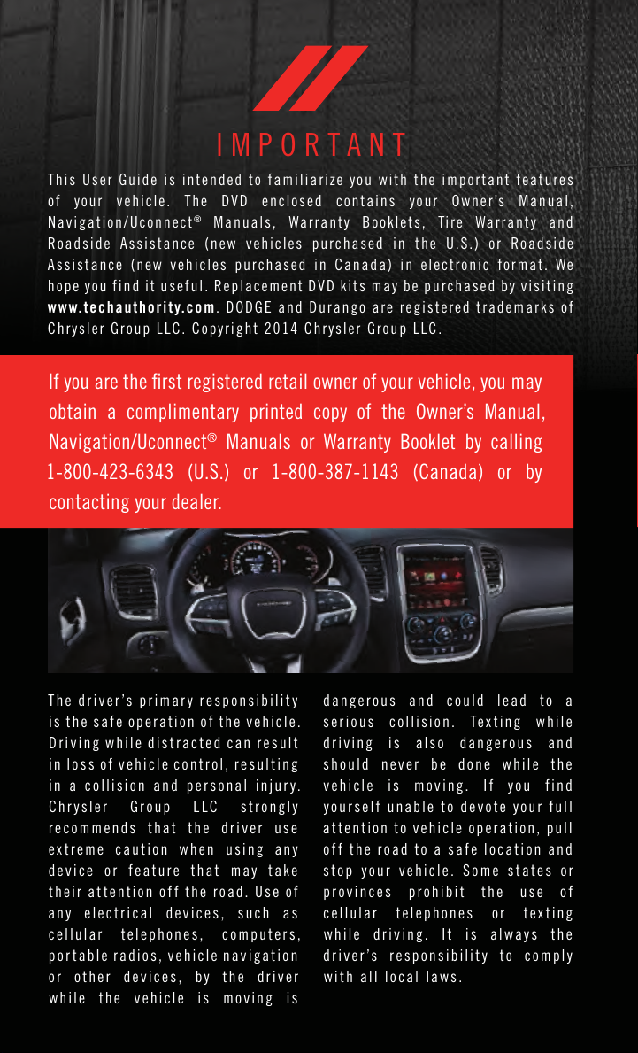
IMPORTANT
This U s er Gu id e is in te nded t o f amil ia r ize yo u with t h e im po rt ant fe at u res
of yo ur ve h icle . The D V D en cl osed c on ta ins y o ur Ow ner’s Ma nual ,
Navigation/Uconnect
Road si d e A ss i stan ce ( new v eh i cles p urch as e d i n t h e U .S .) o r R o ads id e
Assi st a nce ( n ew ve h icl es purc ha se d in C anad a) in el e ctro ni c fo rm at . We
hope you fin d it use fu l . R epla ce m ent DVD kit s may be pur ch a sed by vis it i ng
www.techauthority.com. D OD G E a nd D uran go are re gist er ed tra de m arks o f
Chrysler Group LLC. Copyright 2014 Chrysler Group LLC.
If you are the rst registered retail owner of your vehicle, you may
obtain a complimentary printed copy of the Owner’s Manual,
Navigation/Uconnect
1-800-423-6343 (U.S.) or 1-800-387-1143 (Canada) or by
contacting your dealer.
®
M a nua ls , W a rran ty B oo k let s, Tir e War ra n ty a nd
®
Manuals or Warranty Booklet by calling
T h e driver ’s p ri ma r y re spons ib il i t y
is t h e s a f e o p e r ation of t h e v e h icle .
D r i ving w h ile distracted c an r es ul t
in l o s s o f v eh ic le contr ol, re sulti ng
in a c ol li s i o n an d p er sona l i njur y.
Chr y s l e r G r o up L L C s t r o ngly
r e c o mmends that t he d r i v e r u s e
e x tr em e c aution when usi ng an y
d evice or featur e tha t ma y t ak e
their a tt en ti on o ff t h e road . Us e o f
any e l e c t r i c a l d ev ic es, such a s
c e llul ar t elephones, c o mputers,
p o r ta bl e r ad io s, vehi cl e nav ig at io n
o r o th er d evic es, b y t he d ri ver
w hile the v eh ic le i s mo vi ng i s
dang er ous and c o uld l e ad t o a
s e r i ous c o llis io n. Te x ting whil e
driving is a l s o d a ngerous and
should n e v e r b e d on e w h ile t h e
v ehicle is m ovin g. I f yo u fi nd
y o ur s elf una bl e to d ev ote y our fu ll
at t ention t o ve hi cl e operat io n, p ull
o f f the r oad t o a safe l ocati on a nd
s t o p y our vehi cl e. S o m e s t ates or
p r o v inces pr oh ib it t he u s e of
c e llul ar t e l e phones o r t e x t i ng
w hile drivin g. I t i s al way s t h e
driver ’s r e sp on si b ilit y t o c om p l y
with all local laws.

TABLE OF CONTENTS
INTRODUCTION/WELCOME
WELCOME FROM CHRYSLER
GROUP LLC ..................3
CONTROLS AT A GLANCE
DRIVER COCKPIT ...............6
INSTRUMENT CLUSTER ...........8
GETTING STARTED
KEY FOB . . . . . . . . . . . . . . . . . . . 10
REMOTE START . . . . . . . . . . . . . . . . 11
KEYLESS ENTER-N-GO™ .........11
VEHICLE SECURITY ALARM ........15
SEA T BELT SYSTEMS ............ 15
SUPPLEMENTAL RESTRAINT
SYSTEM (SRS) — AIR BAGS ........16
CHILD RESTRAINTS ............19
HEAD RESTRAINTS .............25
FRONT SEATS .................27
REAR SEATS ................. 31
HEA TED/VENTILATED SEATS ........33
HEA TED STEERING WHEEL ........35
TIL T/TELESCOPING STEERING
COLUMN ...................36
OPERATING YOUR VEHICLE
ENGINE BREAK-IN
RECOMMENDA TIONS ............38
TURN SIGNAL/WIPER/WASHER/HIGH
BEAM LEVER .................38
HEADLIGHT SWITCH ............40
ELECTRONIC SPEED CONTROL ...... 41
ADAPTIVE CRUISE CONTROL (ACC) ....43
FORWARD COLLISION WARNING (FCW)
WITH MITIGATION .............. 47
AUTOMA TIC DIMMING MIRRORS .....49
ELECTRONIC SHIFTER ...........49
AUTOSTICK ..................50
FUEL ECONOMY (ECO) MODE .......52
AUTOMA TIC CLIMATE CONTROLS .....53
PARKSE NSE
PARKVI EW
BLIND SPOT MONITORING .........58
POWER SUNROOF .............. 58
WIND BUFFETING ..............59
®
REAR PARK ASSIST ....57
®
REAR BACK-UP CAMERA . . 57
ELECTRONICS
YOUR VEHICLE'S SOUND SYSTEM .... 60
IDENTIFYING YOUR RADIO ......... 62
®
Uconnect
Uconnect
Uconnect
Uconnect
Uconnect
STEERING WHEEL AUDIO CONTROLS
DRIVER INFORMATION DISPLAY (DID)
PROGRAMMABLE FEATURES .......145
ACCESS .............63
®
5.0 . . . . . . . . . . . . . . . . 80
®
8.4A ...............92
®
8.4AN .............118
®
PHONE .............132
..142
..143
UNIVERSAL GARAGE DOOR OPENER
(HomeLink
POWER INVERTER .............149
POWER OUTLET ..............150
®
).................146
OFF-ROAD CAPABILITIES
ALL-WHEEL DRIVE OPERATION .....152
UTILITY
ROOF LUGGAGE RACK ..........154
TRAILER TOWING WEIGHTS (MAXIMUM
TRAILER WEIGHT RATINGS) .......154
RECREA TIONAL TOWING (BEHIND
MOTORHOME, ETC.) ............156
WHAT TO DO IN EMERGENCIES
ROADSIDE ASSISTANCE ..........161
INSTRUMENT CLUSTER WARNING
LIGHTS ....................161
INSTRUMENT CLUSTER INDICATOR
LIGHTS ...................166
IF YOUR ENGINE OVERHEA TS ...... 168
JACKING AND TIRE CHANGING .....169
BA TTERY LOCATION ............180
JUMP-STAR TING ..............180
MANUAL PARK RELEASE .........182
TOWING A DISABLED VEHICLE ..... 184
FREEING A STUCK VEHICLE .......185
EVENT DATA RECORDER (EDR) .....186
CAP-LESS FUEL FILL FUNNEL ......186
MAINTAINING YOUR VEHICLE
OPENING THE HOOD ...........187
ENGINE COMPARTMENT .........188
FLUID CAPACITIES .............192
FLUIDS, LUBRICANTS AND GENUINE
PART S . . . . . . . . . . . . . . . . . . . . 192
MAINTENANCE PROCEDURES ......194
MAINTENANCE SCHEDULE .......194
MAINTENANCE RECORD .........198
FUSES ....................199
TIRE PRESSURES .............202
ADDING FUEL ................203
SPARE TIRES — IF EQUIPPED ......205
WHEEL AND WHEEL TRIM CARE ....206
REPLACEMENT BULBS ..........207
CUSTOMER ASSISTANCE
CHRYSLER GROUP LLC CUSTOMER
CENTER ...................208
CHRYSLER CANADA INC. CUSTOMER
CENTER ...................208
ASSISTANCE FOR THE HEARING
IMPAIRED ..................208
PUBLICA TIONS ORDERING ........208
REPORTING SAFETY DEFECTS IN THE
UNITED STATES ..............209

TABLE OF CONTENTS
MOPAR® ACCESSORIES
AUTHENTIC ACCESSORIES BY
MOPAR®...................210
FREQUENTLY ASKED QUESTIONS
FREQUENTL Y ASKED QUESTIONS ....211
INDEX
.....................213
2

INTRODUCTION/WELCOME
WELCOME FROM CHRYSLER GROUP LLC
Congratulations on selecting your new Chrysler Group LLC vehicle. Be assured that it
represents precision workmanship, distinctive styling, and high quality - all essentials that
are traditional to our vehicles.
Your ne w Chrysl er Group LLC ve hicle ha s char acteris tics t o enha nce th e driver 's control
under some driving conditions. These are to assist the driver and are never a substitute for
attentive driving. They can never take the driver's place. Always drive carefully.
Your new vehicle ha s ma ny f eatures for the comfort and conveni ence of you and your
passengers. Some of these should not be used when driving because they take your eyes
from the road or your attention from driving. Never text while driving or take your eyes more
than momentarily off the road.
This guide illustrates and describes the operation of features and equipment that are
either standard or optional on this vehicle. This guide may also include a description of
features and equipment that are no longer available or were not ordered on this vehicle.
Please disregard any features and equipment described in this guide that are not available
on this vehicle. Chrysler Group LLC reserves the right to make changes in design and
specifications and/or make additions to or improvements to its products without imposing
any obligation upon itself to install them on products previously manufactured.
This User Guide has been prepared to help you quickly become acquainted with the
important features of your vehicle. It contains most things you will need to operate and
maintain the vehicle, including emergency information.
The DVD includes a computer application containing detailed owner's information which
can be viewed on a personal computer or MAC computer. The multimedia DVD also
includes videos which can be played on any standard DVD player (including the
Uconnect
DVD operational information is located on the back of the DVD sleeve.
For complete owner information, refer to your Owner's Manual on the DVD in the owner’s
kit provided at the time of new vehicle purchase. For your convenience, the information
contained on the DVD may also be printed and saved for future reference.
Chrysler Group LLC is committed to protecting our environment and natural resources. By
converting from paper to electronic delivery for the majority of the user information for
your vehicle, together we greatly reduce the demand for tree-based products and lessen
the stress on our environment.
®
Touc hsc r een R a dio s i f equ i ppe d w ith D V D pla y er c a pab ili t ies ). Add iti o nal
3

INTRODUCTION/WELCOME
VEHICLES SOLD IN CANADA
With respect to any vehicles sold in Canada, the name Chrysler Group LLC shall be
deemed to be deleted and the name Chrysler Canada Inc. used in substitution (excluding
legal lines).
WARNING!
•Pedalsthatcannotmovefreelycancauselossofvehiclecontrolandincreasethe
risk of serious personal injury.
•Alwaysmakesurethatobjectscannotfallintothedriverfootwellwhilethevehicle
is moving. Objects can become trapped under the brake pedal and accelerator
pedal causing a loss of vehicle control.
•Failuretoproperlyfollowfloormatinstallationormountingcancauseinterference
with the brake pedal and accelerator pedal operation causing loss of control of the
vehicle.
•Neverleavechildrenaloneinavehicle,orwithaccesstoanunlockedvehicle.
Allowing children to be in a vehicle unattended is dangerous for a number of
reasons. A child or others could be seriously or fatally injured. Children should be
warned not to touch the parking brake, brake pedal or the shift lever/transmission
gear selector.
•Donotleavethekeyfobinornearthevehicle,orinalocationaccessibletochildren,
and do not leave the ignition of a vehicle equipped with Keyless Enter-N-Go in the
ACC or ON/RUN mode. A child could operate power windows, other controls, or
move the vehicle.
•Neverusethe“PARK”positionasasubstitutefortheparkingbrake.Alwaysapply
the parking brake fully when parked to guard against vehicle movement and
possible injury or damage.
•RefertoyourOwner'sManualontheDVDforfurtherdetails.
4
INTRODUCTION/WELCOME
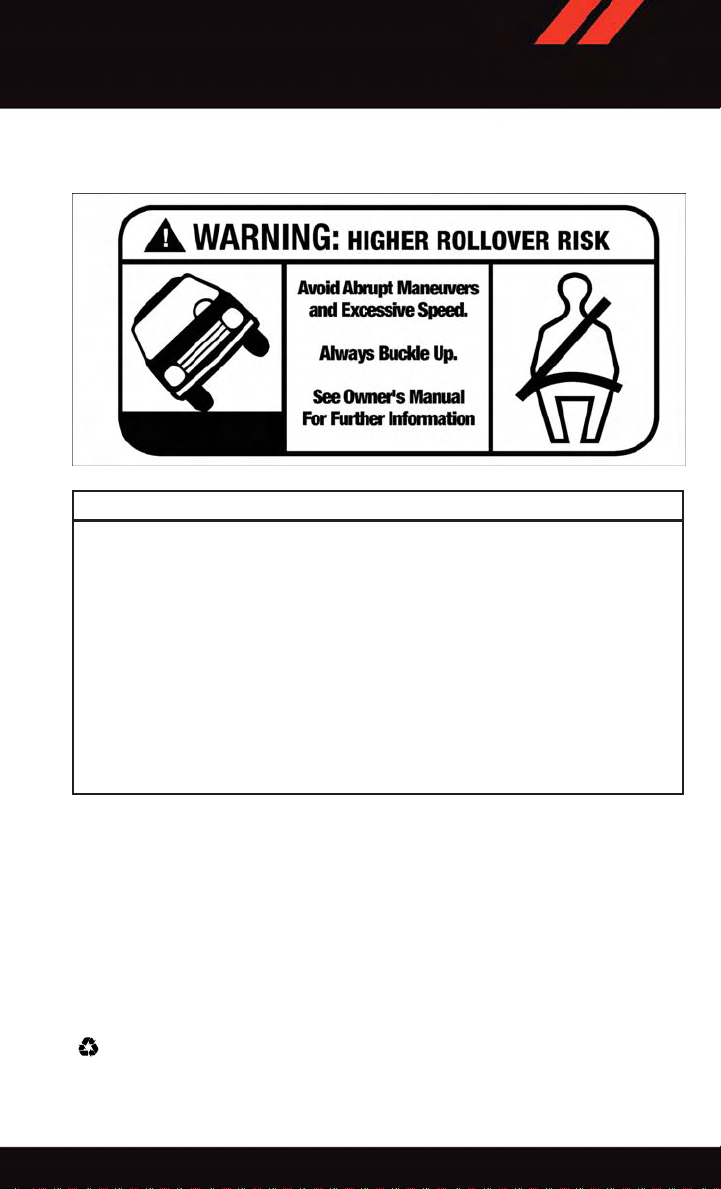
Rollover Warning
WARNING!
•Pedalsthatcannotmovefreelycancauselossofvehiclecontrolandincreasethe
risk of serious personal injury.
•Alwaysmakesurethatobjectscannotfallintothedriverfootwellwhilethevehicle
is moving. Objects can become trapped under the brake pedal and accelerator
pedal causing a loss of vehicle control.
•Failuretoproperlyfollowfloormatinstallationormountingcancauseinterference
with the brake pedal and accelerator pedal operation causing loss of control of the
vehicle.
•RefertoyourOwner'sManualontheDVDforfurtherdetails.
•Neverusethe‘PARK’positionasasubstitutefortheparkingbrake.Alwaysapply
the parking brake fully when parked to guard against vehicle movement and
possible injury or damage.
USE OF AFTERMARKET PRODUCTS (ELECTRONICS)
The use of aftermarket devices including cell phones, MP3 players, GPS systems, or
chargers may affect the performance of on-board wireless features including Keyless
Enter-N-Go™ and Remote Start range. If you are experiencing difficulties with any of your
wireless features, try disconnecting your aftermarket devices to see if the situation
improves. If your symptoms persist, please see an authorized dealer.
CHRYSLER, DODGE, JEEP, RAM, MOPAR and Uconnect are registered trademarks of
Chrysler Group LLC.
COPYRIGHT ©2014 CHRYSLER GROUP LLC
5
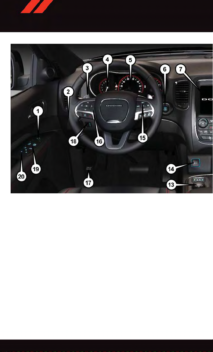
CONTROLS AT A GLANCE
DRIVER COCKPIT
1. Power Mirror Controls
2. Headlight Switch pg. 40
3. Shifter Paddle (AutoStick) pg. 50
4. Instrument Cluster pg. 8
5. Driver Information Display (DID)
6. Engine Start/Stop Button (Behind Steering Wheel) pg. 13
7. Audio System (T ouchscreen Radio Shown) pg. 62
8. Passenger Power Window Controls
9. Glove Compartment
10. Audio Browse/Enter Button pg. 80
6
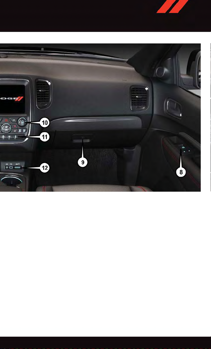
CONTROLS AT A GLANCE
11. Switch Panel
•ParkSense
•ECOOnpg.52
•ElectronicStabilityControl(ESC)OFFpg.167
•ForwardCollisionWarning(FCW)pg.47
12. Media Hub
•AudioJack(AUX)
•USBPort
•SDPort
13. Transmission Gear Selector pg. 49
14. Front Power Outlet pg. 150
15. Speed Control pg. 41
16. Driver Information Display Controls pg. 143
17. Parking Brake Release
18. Instrument Panel Dimmer pg. 40
19. Power Windows
20. Power Door Locks
®
pg. 57
7
CONTROLS AT A GLANCE
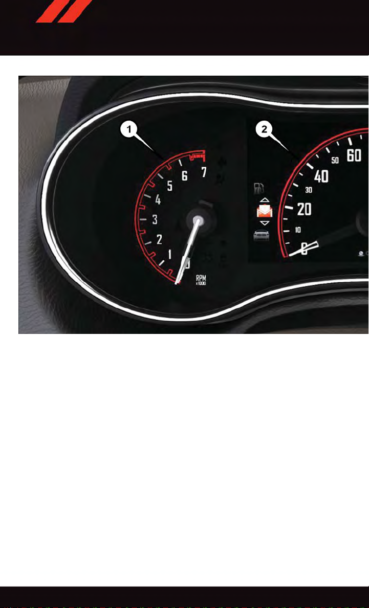
INSTRUMENT CLUSTER
1. Tachometer
2. Speedometer
(See page 161 for Instrument Cluster Warning Lights.)
8
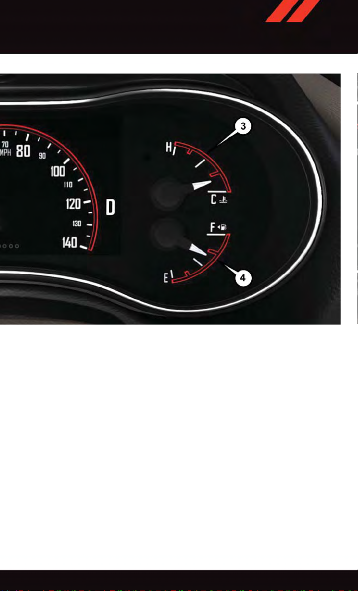
CONTROLS AT A GLANCE
3. Temperature Gauge
4. Fuel Gauge
(See page 166 for Instrument Cluster Indicator Lights.)
9
GETTING STARTED
KEY FOB
Locking And Unlocking The Doors And Liftgate
Lock The Doors And Liftgate
•PushandreleasetheLOCKbuttonon
the RKE transmitter to lock all doors and
liftgate. The turn signal lights will flash,
and the horn will chirp to acknowledge
the signal.
Unlock The Doors And Liftgate
•PushandreleasetheUNLOCKbuttonon
the RKE transmitter once to unlock the
driver’s door or twice within five seconds
to unlock all doors and liftgate. The turn
signal lights will flash to acknowledge the
unlock signal. The illuminated entry system will also turn on.
All doors can be programmed to unlock on
the first push of the UNLOCK button. Refer
to “Programmable Features” in the “Electronics” section of this guide.
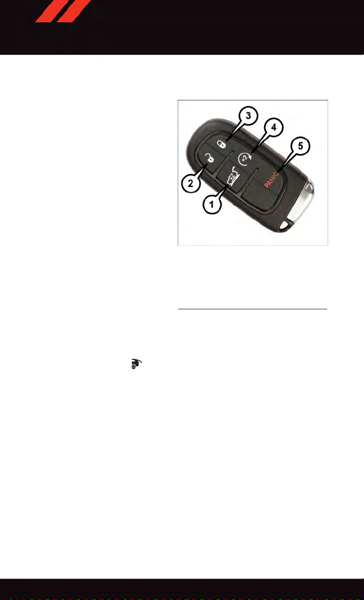
1—Liftgate 4—RemoteStart
2—Unlock 5—Panic
3—Lock
Key Fob
POWER LIFTGATE
•PushtheLIFTGATEbutton twice within five seconds to power open/close the
Power Liftgate. If the button is pushed while the liftgate is being power closed, the
liftgate will reverse to the full open position.
•Also,thePowerLiftgatemaybeclosedbypushingtheliftgateswitchlocatedontheleft
rear trim panel, near the liftgate opening. Pushing once will close the liftgate only. This
button cannot be used to open the liftgate.
Panic Alarm
1. Push the PANIC button once to turn the panic alarm on.
2. Wait approximately three seconds and push the button a second time to turn the panic
alarm off.
10
GETTING STARTED
REMOTE START
x
•PushtheREMOTESTARTbutton
Pushing the REMOTE STAR T button a third time shuts the engine off.
•Todrivethevehicle,withavalidKeylessEnter-N-Go™KeyFobwithin5ft(1.5m)of
the driver's side of the vehicle, grab the front driver door handle to unlock the driver's
door automatically and then push the Start/Stop switch, or push the UNLOCK button,
insert the Key Fob in the ignition and turn to the ON/RUN position.
•Withremotestart,theenginewillonlyrunfor15minutes(timeout)unlesstheignition
is placed in the ON/RUN position.
•ThevehiclemustbestartedwiththeKeyFobaftertwoconsecutivetimeouts.
•Donotstartorrunanengineinaclosedgarageorconfinedarea.Exhaustgas
contains Carbon Monoxide (CO) which is odorless and colorless. Carbon Monoxide
is poisonous and can cause you or others to be severely injured or killed when
inhaled.
•KeepKeyFobtransmittersawayfromchildren.OperationoftheRemoteStart
System, windows, door locks or other controls could cause you and others to be
severely injured or killed.
KEYLESS ENTER-N-GO™
2
on the Key Fob twice within five seconds.
WARNING!
The Keyless Enter-N-Go™ system is an enhancement to the vehicle's Key Fob. This
feature allows you to lock and unlock the vehicle's door(s) and liftgate without having to
push the Key Fob lock or unlock buttons as well as starting and stopping the vehicle with
the push of a button.
11
GETTING STARTED
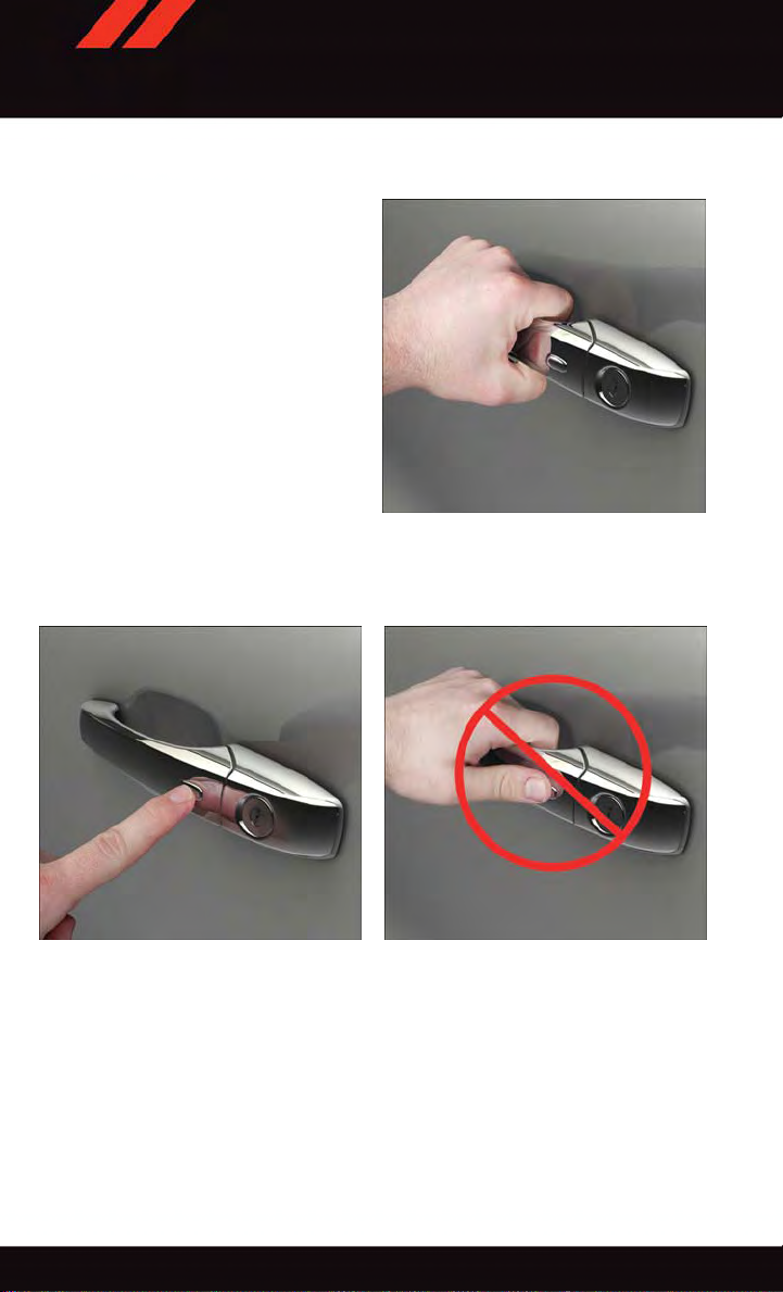
To Unlock From The Driver Or Passenger Side
•WithavalidKeylessEnter-N-Go™Key
Fob located outside the vehicle and
within 5 ft (1.5m) of the driver or passenger side door handle, grab either
front door handle to unlock the door
automatically.
To Lock The Vehicle
•Bothfrontdoorhandleshavebuttons
located on the outside of the handle.
With one of the vehicle's Keyless EnterN-Go™ Key Fobs located outside the
vehicle and within 5 ft (1.5m) of the
driver's or passenger front door handle,
push the door handle button to lock all
four doors and liftgate.
•DONOTgrabthedoorhandlewhenpushingthedoorhandlelockbutton.Thiscould
unlock the door(s).
Grab The Door Handle To Unlock
Push The Door Handle Button To Lock Do NOT Grab Handle When Locking
NOTE:
•“1stPressofKeyFobUnlocks”hastwooptionsavailable.“DriverDoor”and“All
Doors” will unlock when you grab hold of the front driver's door handle. To select
between “Driver Door” and “All Doors,” refer to “Uconnect
Owner's Manual on the DVD.
•IfaKeyFobisdetectedinthevehiclewhenlockingthevehicleusingthepowerdoor
lock switch, the doors and liftgate will unlock, and the horn will chirp three times.
On the third attempt, your Key Fob can be locked inside the vehicle.
®
Settings” in your vehicle's
12
GETTING STARTED
•AfterpushingtheKeylessEnter-N-Go™LOCKbutton,youmustwaittwoseconds
before you can lock or unlock the vehicle using the door handle. This is done to allow
you to check if the vehicle is locked by pulling the door handle, without the vehicle
reacting and unlocking.
•IfaKeylessEnter-N-Go™doorhandlehasnotbeenusedfor72hours,theKeyless
Enter-N-Go™ feature for that handle may time out. Pulling the deactivated front door
handle will reactivate the door handle's Keyless Enter-N-Go™ feature.
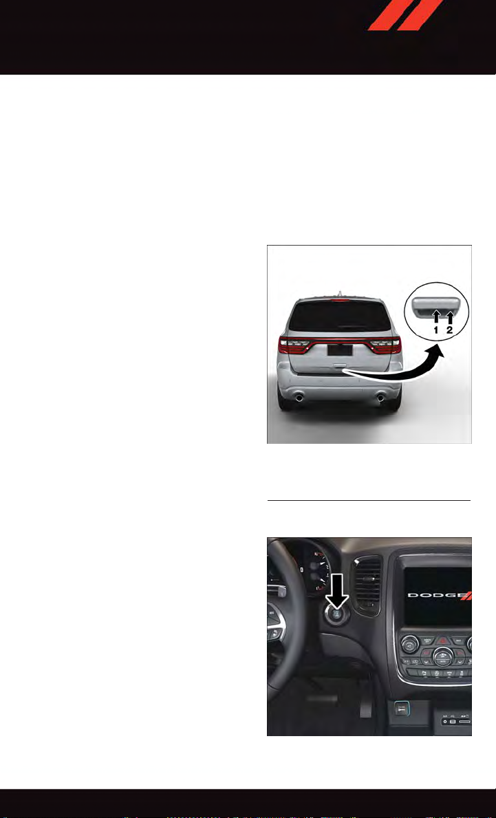
Lock Or Unlock The Liftgate
•ToLockTheLiftgate—WithaRemote
Keyless Entry (RKE) transmitter within
3ft(1.0m)oftheliftgate,pushthe
passive entry lock button located to the
right of electronic liftgate handle.
•ToUnlock/EnterTheLiftgate—Theliftgate passive entry unlock feature is built
into the electronic liftgate handle. With a
Remote Keyless Entry (RKE) transmitter
within 3 ft (1.0 m) of the liftgate, push
the electronic release switch to open the
liftgate.
NOTE:
Refer to your Owner's Manual on the DVD
for further information.
1—ElectronicReleaseSwitch
2—LockButtonLocation
Electronic Liftgate Handle
Engine Starting/Stopping
Starting
Perform the following starting procedure
with a Remote Keyless Entry (RKE) transmitter inside the vehicle:
1. While pushing the brake pedal, push the
ENGINE START/STOP button once. If
the engine fails to start, the starter will
disengage automatically after 10 seconds.
2. To stop the cranking of the engine prior
to the engine starting, push the button
again.
Engine START/STOP Button
13
GETTING STARTED
Stopping
1. Bring the vehicle to a complete stop.
2. Shift the T ransmission to PARK (P).
3. Push the ENGINE START/STOP button once. The ignition switch will return to the OFF
position.
NOTE:
If the transmission is not in PARK and the vehicle is in motion, the ENGINE START/STOP
button must be held for two seconds with the vehicle speed above 5 mph (8 km/h) before
the engine will shut off.
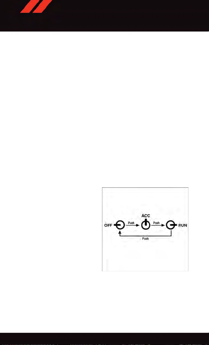
Accessory Positions With Engine Off
NOTE:
The following functions are with the driver’s foot off of the Brake Pedal (transmission in
PARK or N EUTRAL).
Beginning With The Ignition Switch In The OFF Position:
1. Push the ENGINE START/STOP button once to cycle the ignition to the ACC position.
2. Push the ENGINE START/STOP button a second time to cycle the ignition to the
ON/RUN position.
3. Push the ENGINE STAR T/STOP button a third time to return the ignition to the OFF
position.
NOTE:
If the ignition is left in the ACC or ON/RUN
(engine not running) position and the transmission is in PARK, the system will automatically time out after 30 minutes of inactivity, and the ignition is returned to the OFF
position.
14
Ignition Positions

GETTING STARTED
VEHICLE SECURITY ALARM
The Vehicle Security Alarm monitors the vehicle doors for unauthorized entry and the
Keyless Enter-N-Go™ STAR T/STOP button for unauthorized operation. While the Vehicle
Security Alarm is armed, interior switches for door locks and decklid release are disabled.
If something triggers the alarm, the Vehicle Security Alarm will provide the following
audible and visible signals: the horn will pulse, the park lamps and/or turn signals will
flash, and the Vehicle Security Light in the instrument cluster will flash.
To Arm
Cycle the Keyless Enter-N-Go™ START/STOP button until the button display indicates
that the vehicle ignition is “OFF.” Push the power door lock switch while the door is open,
push the Key Fob LOCK button, or with one of the Key Fobs located outside the vehicle
and within 5 ft (1.5 m) of the driver's and passenger front door handles, push the Keyless
Enter-N-Go™ LOCK button located on the door handle.
NOTE:
After pushing the Keyless Enter-N-Go™ LOCK button, you must wait two seconds before
you can lock or unlock the vehicle via the door handle.
To Disarm
Push the Key Fob UNLOCK button or with one of the Key Fobs located outside the vehicle
and within 5 ft (1.5 m) of the driver's and passenger front door handles. Grab the Keyless
Enter-N-Go™ door handle and enter the vehicle, then push the Keyless Enter-N-Go™
STAR T/STOP button (requires at least one valid Key Fob in the vehicle).
SEAT BELT SYSTEMS
Lap/Shoulder Belts
•Allseatingpositionsinyourvehicleareequippedwithlap/shoulderbelts.
•Besureeveryoneinyourvehicleisinaseatandusingaseatbeltproperly.
•Positionthelapbeltsothatitissnugandlieslowacrossyourhips,belowyour
abdomen. To remove slack in the lap belt portion, pull up on the shoulder belt. To loosen
the lap belt if it is too tight, tilt the latch plate and pull on the lap belt. A snug seat belt
reduces the risk of sliding under the seat belt in a collision.
•Positiontheshoulderbeltacrosstheshoulderandchestwithminimal,ifanyslackso
that it is comfortable and not resting on your neck. The retractor will withdraw any slack
in the shoulder belt.
Seat Belt Pretensioner
•Thefrontseatbeltsystemisequippedwithpretensioningdevicesthataredesignedto
remove slack from the seat belt in the event of a collision.
•Adeployedpretensioneroradeployedairbagmustbereplacedimmediately.
15

GETTING STARTED
WARNING!
•Inacollision,youandyourpassengerscansuffermuchgreaterinjuriesifyouare
not properly buckled up. You can strike the interior of your vehicle or other
passengers, or you can be thrown out of the vehicle. Always be sure you and others
in your vehicle are buckled up properly.
•Ashoulderbeltplacedbehindyouwillnotprotectyoufrominjuryduringacollision.
You a re more likely to hit yo ur h ead in a co llision if you do not wear y our shoulde r
belt. The lap and shoulder belt are meant to be used together.
•Aseatbeltthatistooloosewillnotprotectyouproperly.Inasuddenstop,youcould
move too far forward, increasing the possibility of injury. Wear your seat belt snugly.
•Afrayedortornseatbeltcouldripapartinacollisionandleaveyouwithno
protection. Inspect the seat belt system periodically, checking for cuts, frays, or
loose parts. Damaged parts must be replaced immediately. Do not disassemble or
modify the system. Seat belt assemblies must be replaced after a collision.
SUPPLEMENTAL RESTRAINT SYSTEM (SRS) — AIR BAGS
Air Bag System Components
Your vehicle ma y be equipped with the followi ng air bag system compon ents:
•OccupantRestraintController(ORC)
•AirBagWarningLight
•SteeringWheelandColumn
•InstrumentPanel
•KneeImpactBolsters
•AdvancedFrontAirBags
•SupplementalSideAirBags
•SupplementalKneeAirBags
•FrontandSideImpactSensors
•SeatBeltPretenioners
•SeatBeltBuckleSwitch
•SeatTrackPositionSensors
Advanced Front Air Bags
•ThisvehiclehasAdvancedFrontAirBagsforboththedriverandfrontpassengerasa
supplement to the seat belt restraint systems. The Advanced Front Air Bags will not
deploy in every type of collision.
•AdvancedFrontAirBagsaredesignedtoprovideadditionalprotectionbysupplementing the seat belts. Advanced Front Air Bags are not expected to reduce the risk of injury
in rear, side, or rollover collisions.
16

GETTING STARTED
•TheAdvancedFrontAirBagswillnotdeployinallfrontalcollisions,includingsome
that may produce substantial vehicle damage — for example, some pole collisions,
truck underrides, and angle offset collisions.
•Ontheotherhand,dependingonthetypeandlocationofimpact,AdvancedFrontAir
Bags may deploy in crashes with little vehicle front-end damage but that produce a
severe initial deceleration.
•Becauseairbagsensorsmeasurevehicledecelerationovertime,vehiclespeedand
damage by themselves are not good indicators of whether or not an air bag should have
deployed.
•Seatbeltsarenecessaryforyourprotectioninallcollisions,andalsoareneededtohelp
keep you in position, away from an inflating air bag.
•Theairbagsmustbereadytoinflateforyourprotectioninacollision.TheOccupant
Restraint Controller (ORC) monitors the internal circuits and interconnecting wiring
associated with air bag system electrical components.
•TheORCturnsontheAirBagWarningLightintheinstrumentpanelforapproximately
four to eight seconds for a self-check when the ignition switch is first turned to the
ON/RUN position. After the self-check, the Air Bag Warning Light will turn off. If the
ORC detects a malfunction in any part of the system, it turns on the Air Bag Warning
Light, either momentarily or continuously. A single chime will sound to alert you if the
light comes on again after initial startup.
•TheORCmonitorsthereadinessoftheelectronicpartsoftheairbagsystemwhenever
the ignition switch is in the START or ON/RUN position. If the ignition switch is in the
OFF position or in the ACC position, the air bag system is not on and the air bags will
not inflate.
•IftheAirBagWarningLightintheinstrumentpanelisnotonduringthefourtoeight
seconds when the ignition switch is first turned to the ON/RUN position, stays on, or
turns on while driving, have the vehicle serviced by an authorized service center
immediately.
NOTE:
If the speedometer, tachometer, or any engine related gauges are not working, the
Occupant Restraint Controller (ORC) may also be disabled. In this condition the air bags
may not be ready to inflate for your protection. Have an authorized dealer service the air
bag system immediately.
•Afteranycollision,thevehicleshouldbetakentoanauthorizeddealerimmediately.
•Donotdriveyourvehicleaftertheairbagshavedeployed.Ifyouareinvolvedinanother
collision, the air bags will not be in place to protect you.
•Ifitisnecessarytomodifytheairbagsystemforpersonswithdisabilities,contactyour
authorized dealer.
•RefertotheOwner'sManualontheDVDforfurtherdetailsregardingtheSupplemental
Restraint System (SRS).
17

GETTING STARTED
Supplemental Knee Air Bags
This vehicle is equipped with a Supplemental Driver Knee Air Bag mounted in the
instrument panel below the steering column. The Supplemental Driver Knee Air Bag
provides enhanced protection during a frontal impact by working together with the seat
belts, pretensioners, and Advanced Front Air Bags.
WARNING!
•Relyingontheairbagsalonecouldleadtomoresevereinjuriesinacollision.The
air bags work with your seat belt to restrain you properly. In some collisions, the air
bags won't deploy at all. Always wear your seat belts even though you have air bags.
•BeingtooclosetothesteeringwheelorinstrumentpanelduringAdvancedFrontAir
Bag deployment could cause serious injury, including death. Air bags need room to
inflate. Sit back, comfortably extending your arms to reach the steering wheel or
instrument panel.
•Noobjectsshouldbeplacedoverorneartheairbagontheinstrumentpanelor
steering wheel because any such objects could cause harm if the vehicle is in a
collision severe enough to cause the air bag to inflate.
Supplemental Side Air Bags
•ThisvehicleisequippedwithSupplementalSeat-MountedSideAirBags(SABs)
located in the outboard side of the front seats. The SABs are marked with a SRS
AIRBAG or AIRBAG label sewn into the outboard side of the seats.
•ThisvehicleisequippedwithSupplementalSideAirBagInflatableCurtains(SABICs)
located above the side windows. The trim covering the SABICs is labeled SRS AIRBAG
or AIRBAG. The SABICs may help reduce the risk of partial or complete ejection of
vehicle occupants through side windows in certain side impact events.
•TheSABICsandSABs(“SideAirBags”)aredesignedtoactivateincertainside
impacts and certain rollover events. The Occupant Restraint Controller (“ORC”)
determines whether the deployment of the Side Air Bags in a particular side impact or
rollover event is appropriate, based on the severity and type of collision. Vehicle damage
by itself is not a good indicator of whether or not Side Air Bags should have deployed.
18

GETTING STARTED
WARNING!
•SideAirBagsneedroomtoinflate.Donotleanagainstthedoororwindow.Sit
upright in the center of the seat.
•BeingtooclosetotheSideAirBagsduringdeploymentcouldcauseyoutobe
severely injured or killed.
•RelyingontheSideAirBagsalonecouldleadtomoresevereinjuriesinacollision.
The Side Air Bags work with your seat belt to restrain you properly. In some
collisions, Side Air Bags won’t deploy at all. Always wear your seat belt even though
you have Side Air Bags.
•
This vehicle is equipped with left and right Supplemental Side Air Bag Inflatable
Curtains (SABICs). Do not stack luggage or other cargo up high enough to block the
deployment of the SABICs. The trim covering above the side windows where the SABIC
and its deployment path are located should remain free from any obstructions.
•ThisvehicleisequippedwithSABICs.InorderfortheSABICstoworkasintended,
do not install any accessory items in your vehicle which could alter the roof. Do not
add an aftermarket sunroof to your vehicle. Do not add roof racks that require
permanent attachments (bolts or screws) for installation on the vehicle roof. Do not
drill into the roof of the vehicle for any reason.
•DonotuseaccessoryseatcoversorplaceobjectsbetweenyouandtheSideAir
Bags; the performance could be adversely affected and/or objects could be pushed
into you, causing serious injury.
CHILD RESTRAINTS
Children 12 years or younger should ride properly buckled up in a rear seat, if available.
According to crash statistics, children are safer when properly restrained in the rear seats
rather than in the front.
Every state in the United States and all Canadian provinces require that small children
ride in proper restraint systems. This is the law, and you can be prosecuted for ignoring it.
NOTE:
•Foradditionalinformation,refertowww.Seatcheck.orgorcall1-866-SEATCHECK.
•CanadianresidentsshouldrefertoTransportCanada’swebsiteforadditionalinformation: http://www.tc.gc.ca/eng/motorvehiclesafety/safedrivers-childsafety-index-53.htm
LATCH – Lower Anchors And Tethers For CHildren
•YourvehicleisequippedwiththechildrestraintanchoragesystemcalledLATCH,
which stands for Lower Anchors and Tethers for CHildren.
•Thesecondrowseatingpositionshaveloweranchorsandtoptetheranchors.The
second row center (60/40 bench seat only) and third row seating positions have a top
tether anchor only.
19
GETTING STARTED
LATCH System Weight Limit
You ma y use the LA TCH anch orage sy stem until th e combin ed we ight of the chil d and the
child restraint is 65 lbs (29.5 kg). Use the seat belt and tether anchor instead of the
LA TCH system once the combined weight is more than 65 lbs (29.5 kg).
Locating LATCH Anchorages
The lower anchorages are round bars that are found at the rear of the seat cushion
where it meets the seatback. They are just visible when you lean into the rear seat to install
the child restraint. You will easily feel them if you run your finger along the gap between
the seatback and seat cushion.
20
Lower Anchors
GETTING STARTED
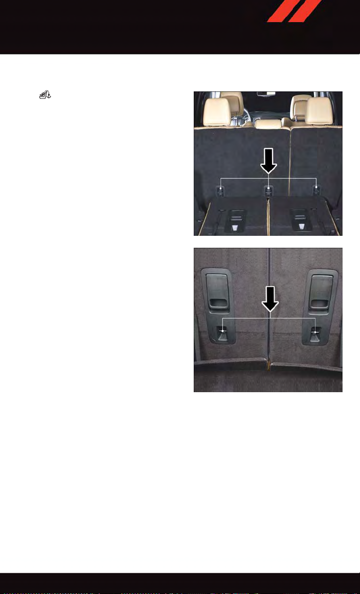
Locating Tether Anchorages
In addition, there are tether strap anchorages behind each rear seating position
located on the back of the seat. To access
the top tether strap anchorages behind the
60/40 Center Row Bench seat or the third
row seat, pull the carpeted floor panel away
from the seat back, this will expose the top
tether strap anchorages. DO NOT USE the
cargo tie down loops located on the load
floor as tether anchorages.
Center Seat LATCH
Do not install a child restraint in the center
position using the LATCH system. Use the
seat belt and tether anchor to install a child
seat in the center seating position.
Tether Anchors Second Row
Tether Anchors Third Row
21
GETTING STARTED
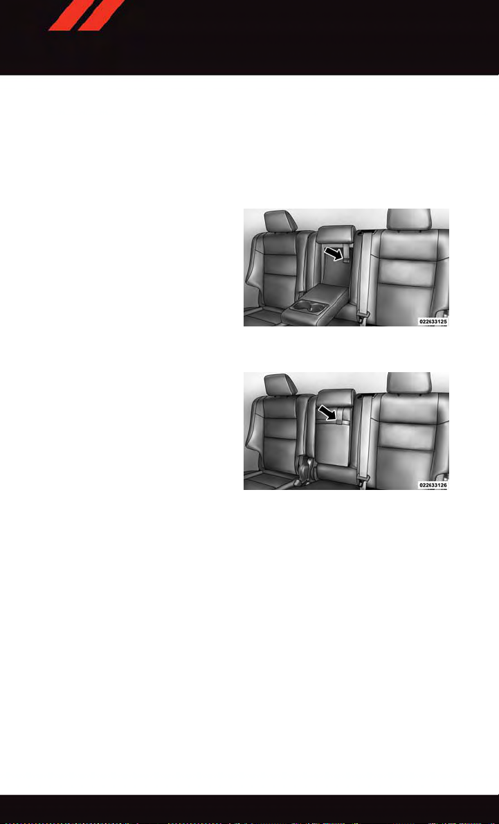
Vehicles With Center Arm Rest Tether
For rearward facing infant seats secured in the center seat position with the vehicle seat
belts, the rear center seat position has an armrest tether that secures the arm rest in the
upward position.
1. To access the center seat arm rest tether, first lower the arm rest. The tether is located
behind the armrest and hooked onto the plastic seat backing.
2. Pull down on the tether to unhook it
from the plastic seat backing.
Center Seat Position Arm Rest Tether
Raise the armrest and attach the tether hook to the strap located on the front of the arm rest.
3.
Center Seat Arm Rest Raised Displaying
The Tether
Installing The Child Restraint Using The LATCH Lower Anchors
NOTE:
Never “share” a LA TCH anchorage with two or more child restraints.
1. Loosen the adjusters on the lower straps and on the tether strap of the child seat so that
you can more easily attach the hooks or connectors to the vehicle anchorages.
2. Attach the lower hooks or connectors of the child restraint to the lower anchorages in
the selected seating position.
3. If the child restraint has a tether strap, connect it to the top tether anchorage. See
below for directions to attach a tether anchor.
4. Tighten all of the straps as you push the child restraint rearward and downward into
the seat. Remove slack in the straps according to the child restraint manufacturer’s
instructions.
5. Test that the child restraint is installed tightly by pulling back and forth on the child
seat at the belt path. It should not move more than 1 inch (25.4 mm) in any direction.
22

GETTING STARTED
Installing The Child Restraint Using The Vehicle Seat Belts
The seat belts in the passenger seating positions are equipped with a Switchable
Automatic Locking Retractor (ALR) that is designed to keep the lap portion of the seat belt
tight around the child restraint. Any seat belt system will loosen with time, so check the
belt occasionally, and pull it tight if necessary.
Tether Anchorage Weight Limit
Always use the tether anchor when using the seat belt to install a forward facing child
restraint, up to the recommended weight limit of the child restraint.
To Install A Child Seat Using An ALR:
1. Pull enough of the seat belt webbing from the retractor to pass it through the belt path
of the child restraint. Do not twist the belt webbing in the belt path.
2. Slide the latch plate into the buckle until you hear a “click.”
3. Pull on the webbing to make the lap portion tight against the child seat.
4. To lock the seat belt, pull down on the shoulder part of the belt until you have pulled
all the seat belt webbing out of the retractor. Then, allow the webbing to retract back
into the retractor. As the webbing retracts, you will hear a clicking sound. This means
the seat belt is now in the Automatic Locking mode.
5. Try to pull the webbing out of the retractor. If it is locked, you should not be able to pull
out any webbing. If the retractor is not locked, repeat the last step.
6. Finally, pull up on any extra webbing to tighten the lap portion around the child
restraint while you push the child restraint rearward and downward into the vehicle
seat.
7. If the child restraint has a top tether strap and the seating position has a top tether
anchorage, connect the tether strap to the anchorage and tighten the tether strap. See
below for directions to attach a tether anchor.
8. Test that the child restraint is installed tightly by pulling back and forth on the child
seat at the belt path. It should not move more than 1 inch (25.4 mm) in any direction.
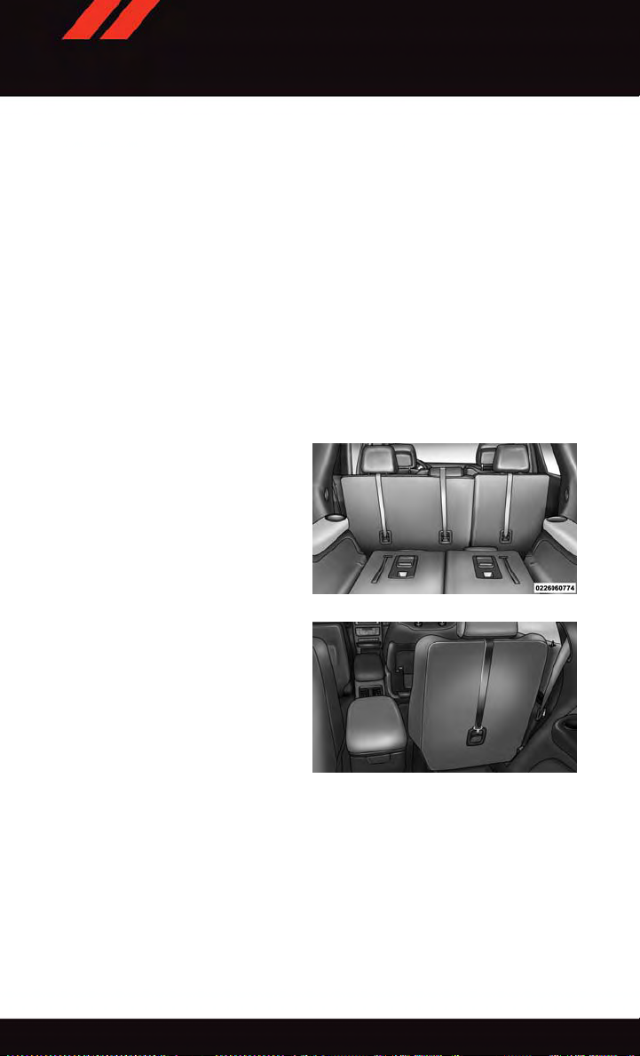
Installing The Top Tether Strap (With Either Lower Anchors Or Vehicle Seat Belt):
When installing a forward-facing child restraint, always secure the top tether strap, up to
the tether anchor weight limit, whether the child restraint is installed with the lower
anchors or the vehicle seat belt.
23
GETTING STARTED
Tether Strap Installation
1. To access the top tether strap anchorages behind the rear seat, pull the carpeted floor
panel away from the seat back, this will expose the top tether strap anchorages.
2. Route the tether strap to provide the most direct path for the strap between the anchor
and the child seat.
3. If your vehicle is equipped with adjustable rear head restraints, raise the head
restraint, and where possible, route the tether strap under the head restraint and
between the two posts. If not possible, lower the head restraint and pass the tether
strap around the outboard side of the head restraint.
4. For the center seating position, route the tether strap over the seatback and headrest.
5. Attach the tether strap hook of the child restraint to the top tether anchorage and
remove slack in the tether strap according to the child restraint manufacturer’s
instructions. DO NOT USE the cargo tie down loops located on the load floor as tether
anchorages.
24
Top Tether Strap Mounting (60/40 Seat)
Top Tether Strap Mounting (Captain's Chair)
GETTING STARTED
WARNING!
•Inacollision,anunrestrainedchild,evenatinybaby,canbecomeaprojectile
inside the vehicle. The force required to hold even an infant on your lap could
become so great that you could not hold the child, no matter how strong you are.
The child and others could be severely injured or killed. Any child riding in your
vehicle should be in a proper restraint for the child's size.
•Rearward-facingchildseatsmustneverbeusedinthefrontseatofavehiclewith
afrontpassengerairbag.Anairbagdeploymentcouldcausesevereinjuryordeath
to infants in this position.
•Onlyusearearward-facingchildrestraintinavehiclewitharearseat.
•ImproperinstallationofachildrestrainttotheLATCHanchoragescanleadto
failure of an infant or child restraint. The child could be severely injured or killed.
Follow the manufacturer’s directions exactly when installing an infant or child
restraint.
•Anincorrectlyanchoredtetherstrapcouldleadtoincreasedheadmotionand
possible injury to the child. Use only the anchor positions directly behind the child
seat to secure a child restraint top tether strap.
•Ifyourvehicleisequippedwithasplitrearseat,makesurethetetherstrapdoesnot
slip into the opening between the seatbacks as you remove slack in the strap.
HEAD RESTRAINTS
Head restraints are designed to reduce the risk of injury by restricting head movement in
the event of a rear-impact. Head restraints should be adjusted so that the top of the head
restraint is located above the top of your ear.
WARNING!
The head restraints for all occupants must be properly adjusted prior to operating the
vehicle or occupying a seat. Head restraints should never be adjusted while the vehicle
is in motion. Driving a vehicle with the head restraints improperly adjusted or removed
could cause serious injury or death in the event of a collision.
Active Head Restraints — Front Seats
Active Head Restraints are passive, deployable components, and vehicles with this
equipment cannot be readily identified by any markings, only through visual inspection of
the head restraint. The Active Head Restraints (AHR) will be split in two halves, with the
front half being soft foam and trim, the back half being decorative plastic.
When AHRs deploy during a rear impact, the front half of the head restraint extends
forward to minimize the gap between the back of the occupant’s head and the AHR. This
system is designed to help prevent or reduce the extent of injuries to the driver and front
passenger in certain types of rear impacts. Refer to “Occupant Restraints” in your Owner’s
Manual on the DVD for further information.
25

GETTING STARTED
To rai s e the hea d r est r ain t, pul l u pwa rd on t h e hea d r est r ain t. To low e r the hea d r est rain t,
press the push button, located at the base of the head restraint, and push downward on
the head restraint.
For comfort the Active Head Restraints can be tilted forward and rearward. T o tilt the head
restraint closer to the back of your head, pull forward on the bottom of the head restraint.
Push rearward on the bottom of the head restraint to move the head restraint away from
your head.
NOTE:
•
The head restraints should only be removed by qualified technicians, for service purposes
only. If either of the head restraints require removal, see your authorized dealer.
•IntheeventofdeploymentofanActiveHeadRestraint,referto“OccupantRestraints”
in your Owner’s Manual on the DVD for further information.
WARNING!
•DonotplaceitemsoverthetopoftheActiveHeadRestraint,suchascoats,seat
covers or portable DVD players. These items may interfere with the operation of the
Active Head Restraint in the event of a collision and could result in serious injury or
death.
•ActiveHeadRestraintsmaybedeployediftheyarestruckbyanobjectsuchasa
hand, foot or loose cargo. To avoid accidental deployment of the Active Head
Restraint ensure that all cargo is secured, as loose cargo could contact the Active
Head Restraint during sudden stops. Failure to follow this warning could cause
personal injury if the Active Head Restraint is deployed.
Head Restraints — Rear Seats
The head restraints on the outboard seats are not adjustable. They automatically fold
forward when the rear seat is folded to a load floor position but do not return to their
normal position when the rear seat is raised. After returning either seat to its upright
position, raise the head restraint until it locks in place. The outboard head restraints are
not removable.
The center head restraint has limited adjustment. Lift upward on the head restraint to
raise it, or push downward on the head restraint to lower it.
WARNING!
Sitting in a seat with the head restraint in its lowered position could result in serious
injury or death in a collision. Always make sure the outboard head restraints are in their
upright positions when the seat is to be occupied.
NOTE:
For proper routing of a Child Seat Tether refer to “Occupant Restraints” in your Owner’s
Manual on the DVD for further information.
26
GETTING STARTED
Power Folding Third Row Head Restraints
For improved visibility when in reverse, the third row head restraints can be folded using
the Uconnect
Press the “Controls” button located on the bottom of the Uconnect
Press the Headrest Fold button
NOTE:
•TheheadrestraintscanonlybefoldeddownwardusingtheHeadrestbutton.Thehead
restraints must be raised manually when occupying the third row.
•Donotfoldiftherearepassengersseatedinthethirdrowseats.
FRONT SEATS
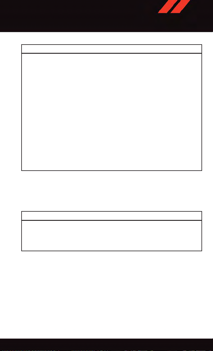
Power Seats
The power recline switch, located on the outboard side of the seat, controls seatback
adjustment.
The power seat switch controls forward/back, up/down and tilt adjustment.
®
System.
®
display.
to power fold the third row head restraints.
Power Seat Switches
1—ReclineSwitch
2—PowerSeatSwitch
27
GETTING STARTED
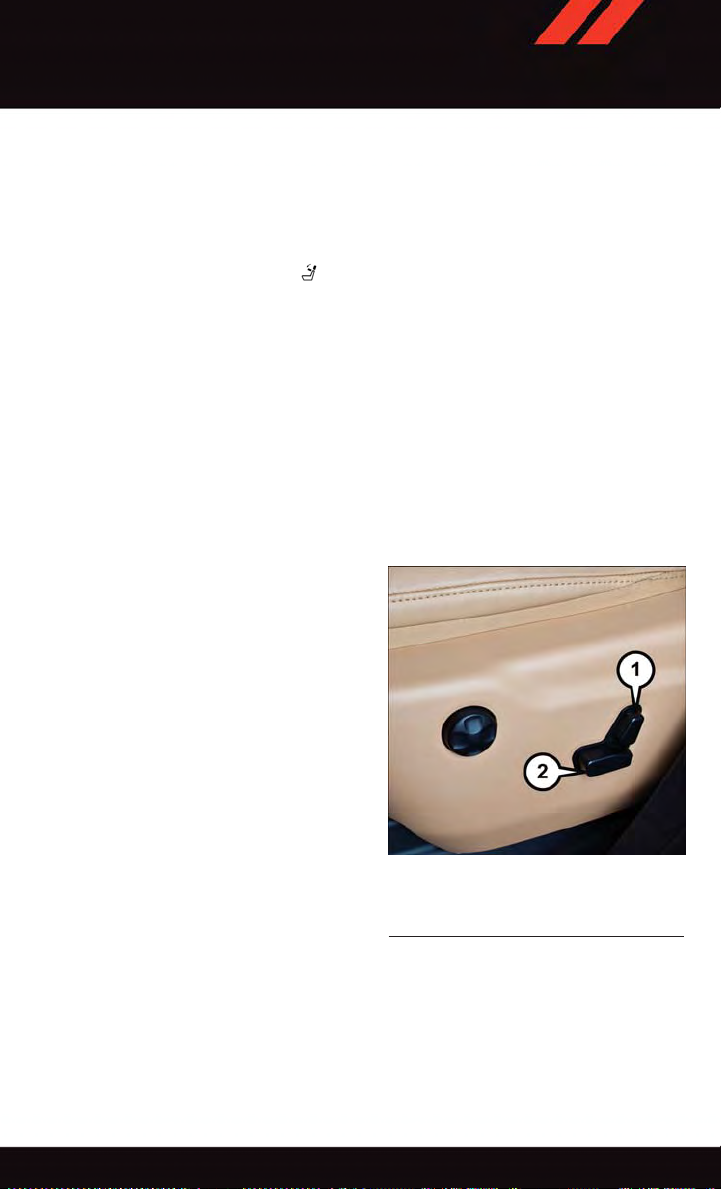
Power Lumbar
•Pushtheswitchforwardtoincreasethe
lumbar support. Push the switch rearward to decrease the lumbar support.
•Pushingupwardordownwardonthe
switch will raise and lower the position of
the support.
Power Lumbar Switch
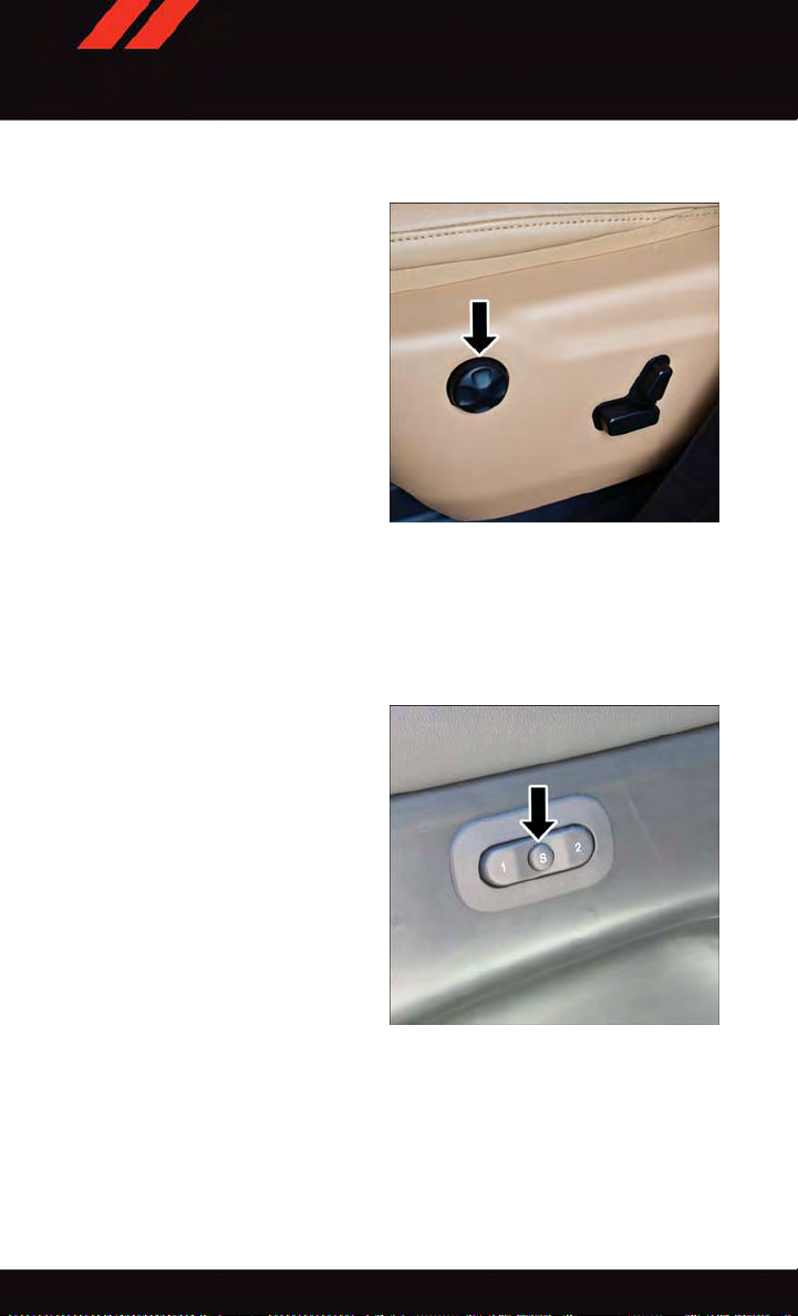
Memory Seat
The memory seat feature allows you to set two different driver seating positions (excluding
lumbar position), outside mirrors, radio station preset settings and tilt/telescoping steering column position (if equipped). The memory seat buttons are located on the driver's
door panel.
To set a memory position:
1. Cycle the vehicles ignition to the ON
position.
2. Adjust all memory profile settings.
3. Press and release the S (SET) button.
4. Press and release the 1 or 2 button
within five seconds.
NOTE:
Before programming your RKE transmitters
you must select the “Personal Settings
Linked T o Key Fob” feature through the
Uconnect
Settings ” in “Understanding Your Instrument Panel” in the Owner's Manual on the
DVD for further details.
®
system. Refer to “Uconnect
®
Memory Seat Buttons
28

GETTING STARTED
To program a Key Fob to the memory position:
1. Cycle the vehicles ignition to the OFF position.
2. Select the desired memory profile 1 or 2.
3. Once the profile has been recalled, press and release the SET (S) button on the
memory switch.
4. Within five seconds, press and release button (1) or (2) accordingly. “Memory Profile
Set” (1 or 2) will display in the instrument cluster.
5. Press and release the LOCK button on the RKE transmitter within 10 seconds.
NOTE:
To rec a ll t h e sav ed pos iti o ns, p r ess 1 o r 2 o n the m e mor y s wit ch or p res s U NLO C K on t h e
programmed RKE transmitter.
Easy Entry/Exit Feature
The memory seat has an Easy Entry/Exit feature. This feature provides automatic driver
seat positioning to enhance driver mobility when entering and exiting the vehicle.
NOTE:
The Easy Entry/Exit feature is not enabled when the vehicle is delivered from the factory .
To e nab le ( or lat er dis a ble ) t his fea tur e y o u m ust sel e ct “Ea sy Exi t S e ats ” i n “ E ngi ne Off
Options” through the programmable features in the Uconnect
•
Refer to “Uconnect®Customer Programmable Features” in “Electronics” of this User Guide.
•Forfurtherdetailsreferto“Uconnect®Settings” in “Understanding Your Instrument
Panel” in the Owner's Manual on the DVD.
®
system.
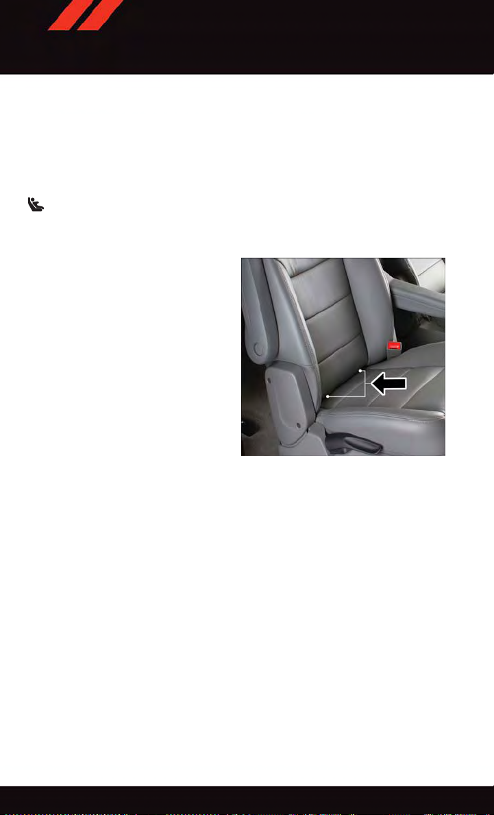
Manual Seat Adjustment
Forward/Rearward
•Liftupontheadjustingbarlocatedat
the front of the seat near the floor and
release it when the seat is at the desired
position. Then, using body pressure,
move forward and backward on the seat
to be sure that the seat adjusters have
latched.
Adjusting Bar Location
29

GETTING STARTED
Recliner
•Lifttherearleverlocatedontheoutboard side of the seat, lean back and
release when seat is in desired position.
Recliner Lever Location
Fold-Flat Front Passenger Seat
The front passenger seat can be folded flat to allow for extended cargo space.
•Pulluponthereclinerleverandfoldtheseatbackforwardanddowntoaflatposition.
CAUTION!
Do not place any article under a power seat or impede its ability to move as it may cause
damage to the seat controls. Seat travel may become limited if movement is stopped
by an obstruction in the seat's path.
WARNING!
•Adjustingaseatwhilethevehicleismovingisdangerous.Thesuddenmovementof
the seat could cause you to lose control. The seat belt might not be properly
adjusted, and you could be severely injured or killed. Only adjust a seat while the
vehicle is parked.
•Donotridewiththeseatbackreclinedsothattheseatbeltisnolongerresting
against your chest. In a collision, you could slide under the seat belt and be severely
injured or killed. Use the recliner only when the vehicle is parked.
30

GETTING STARTED
REAR SEATS
60/40 Split Rear Seat
The left or right side of the second row seatback can be folded flat to carry cargo. The left
and right side of the second row seat can also be tumbled forward to allow access to the
third row seat.
Fold And Tumble
•Pullupwardonthereleaselevertorelease the seat.
NOTE:
Also, pulling upward on this handle allows
the outboard seating positions to be reclined.
•Tumbletheseatforwardusingthered
pull strap located behind the seatback.
NOTE:
If sitting in the third row seat, pull rearward
on the tumble pull strap located at the rear
of the seat and tumble the seat forward.
Seat Release Lever
Tumble Pull Strap
31

GETTING STARTED
Rear Captain Chairs
Fold And Tumble
The left or right side of the second row seatback can be folded flat to carry cargo. When
the lower storage compartment is accessed
using the rear push button it allows the armrest to flip forward for “fold flat mode”.
Fold flat mode allows the console armrest to
be lowered below fold flat seat plane and
protect the armrest vinyl from damage
when using the vehicle to haul cargo.
The left and right side of the second row
seat can also be tumbled forward to allow
access to the third row seat. Pull upward on
the release lever to release the seat. Pulling upward on this handle allows the outboard
seating positions to be reclined.
•Tumbletheseatforwardusingtheredpullstraplocatedbehindtheseatback.
NOTE:
If sitting in the third row seat, pull rearward on the tumble pull strap located at the rear of
the seat and tumble the seat forward.
If your vehicle is equipped with a mini
console there is a stepping pad to allow
passengers to easily access the third row
seats.
Rear Captain Chairs
Stepping Pad Location
50/50 Third Row Folding Seat
Either or both third row seats can be folded forward to increase the rear cargo storage area.
After opening the liftgate, either seat can be folded flat by pulling up the release handle
on the back of the seat.
Aseatthatisfoldedflatcanbereturnedtotheuprightpositionbyusingthepullstrap
located on the back of the seat next to the release handle.
32

GETTING STARTED
NOTE:
The second row seats must be in their full upright position, or tumbled when folding the
third row seats.
•
To rai s e t he s e at, pul l t he sea t t owa rd you usi ng the s t rap loc ate d o n t he bac k o f t he s e at.
WARNING!
Do not drive the vehicle with the second row seats in the tumbled position. The second
row seats are only intended to be tumbled for entry and exit to the third row seat. Failure
to follow these instructions could result in personal injury.
HEATED/VENTILATED SEATS
Heated Seats
On some models, the front and rear seats may be equipped with heaters in both the seat
cushions and seatbacks.
The front driver and passenger heated seats are operated using the Uconnect
WARNING!
•Personswhoareunabletofeelpaintotheskinbecauseofadvancedage,chronic
illness, diabetes, spinal cord injury, medication, alcohol use, exhaustion or other
physical condition must exercise care when using the seat heater. It may cause
burns even at low temperatures, especially if used for long periods of time.
•Donotplaceanythingontheseatorseatbackthatinsulatesagainstheat,suchas
ablanketorcushion.Thismaycausetheseatheatertooverheat.Sittinginaseat
that has been overheated could cause serious burns due to the increased surface
temperature of the seat.
®
System.
Front Heated Seats
The front heated seats control buttons are located within the climate or controls screen of
the touchscreen.
You c an c hoose from H I, LO or O FF h eat s ettings . Th e in dicator lights in each s witch
indicate the level of heat in use. Two indicator lights will illuminate for HI, one for LO and
none for OFF.
•Presstheheatedseatbutton
•Presstheheatedseatbutton
•Presstheheatedseatbutton
once to turn the HI setting ON.
asecondtimetoturntheLOsettingON.
athirdtimetoturntheheatingelementsOFF.
33

GETTING STARTED
If the HI-level setting is selected, the system will automatically switch to LO-level after
approximately 60 minutes of continuous operation. At that time, the display will change
from HI to LO, indicating the change. The LO-level setting will turn OFF automatically
after approximately 45 minutes.
NOTE:
•Onceaheatsettingisselected,heatwillbefeltwithintwotofiveminutes.
•Theenginemustberunningfortheheatedseatstooperate.
Vehicles Equipped With Remote Start
On models that are equipped with remote start, the heated seats can be programed to
come on during a remote start.
This feature can be programmed through the Uconnect
Settings” in “Understanding Your Instrument Panel” in the Owner's Manual on the DVD.
Rear Heated Seats
On some models, the two outboard seats are equipped with heated seats. The heated seat
switches for these seats are located on the rear of the center console. There are two heated
seat switches
You c an c hoose from H I, L O or O FF h eat setting s. T he i ndicato r li ghts in e ach s witch
indicate the level of heat in use. Two indicator lights will illuminate for HI, one for LO and
none for OFF.
•Presstheheatedseatbutton
•Presstheheatedseatbutton
•Presstheheatedseatbutton
that allow the rear passengers to operate the seats independently.
once to select HI-level heating.
asecondtimetoselectLO-levelheating.
athirdtimetoturntheheatingelementsOFF.
®
system. Refer to “Uconnect
®
NOTE:
•Onceaheatsettingisselected,heatwillbefeltwithintwotofiveminutes.
•Theenginemustberunningfortheheatedseatstooperate.
When the HI-level setting is selected, the heater will provide a boosted heat level during
the first four minutes of operation. Then, the heat output will drop to the normal HI-level.
If the HI-level setting is selected, the system will automatically switch to LO-level after
approximately 60 minutes of continuous operation. At that time, the number of illuminated LEDs changes from two to one, indicating the change. The LO-level setting will turn
OFF automatically after approximately 45 minutes.
Front Ventilated Seats
Located in the seat cushion and seat back are small fans that draw the air from the
passenger compartment and move air through fine perforations in the seat cover to help
keep the driver and front passenger cooler in higher ambient temperatures. The fans
operate at two speeds, HI and LO.
34

GETTING STARTED
The front ventilated seats control buttons are located within the Uconnect®system. You
can gain access to the control buttons through the climate screen or the controls screen.
•Presstheventilatedseatbutton
•Presstheventilatedseatbutton
•Presstheventilatedseatbutton
NOTE:
The engine must be running for the ventilated seats to operate.
Vehicles Equipped With Remote Start
On models that are equipped with remote start, the ventilated seats can be programed to
come on during a remote start.
This feature can be programmed through the Uconnect
Settings” in “Understanding Your Instrument Panel” in the Owner's Manual on the DVD.
HEATED STEERING WHEEL
The steering wheel contains a heating element that heats the steering wheel to one
temperature setting.
The heated steering wheel control button is located within the Uconnect
gain access to the control buttons through the climate screen or the controls screen.
•Presstheheatedsteeringwheelbutton
•Presstheheatedsteeringwheelbutton
OFF.
Once the heated steering wheel has been turned on, it will operate for up to 80 minutes
before automatically shutting off. The heated steering wheel can shut off early or may not
turn on when the steering wheel is already warm.
NOTE:
Vehicle Equipped With Remote Start
On models that are equipped with remote start, this feature can be programmed to come
on during a remote start through the Uconnect
in “Understanding Your Instrument Panel” in the Owner's Manual on the DVD.
once to choose HI.
asecondtimetochooseLO.
athirdtimetoturntheventilatedseatOFF.
®
system. Refer to “Uconnect
®
system. You can
once to turn the heating element ON.
asecondtimetoturntheheatingelement
®
system. Refer to “Uconnect®Settings”
®
WARNING!
•Personswhoareunabletofeelpaintotheskinbecauseofadvancedage,chronic
illness, diabetes, spinal cord injury, medication, alcohol use, exhaustion, or other
physical conditions must exercise care when using the steering wheel heater. It may
cause burns even at low temperatures, especially if used for long periods.
•Donotplaceanythingonthesteeringwheelthatinsulatesagainstheat,suchasa
blanket or steering wheel covers of any type and material. This may cause the
steering wheel heater to overheat.
35

GETTING STARTED
TILT/TELESCOPING STEERING COLUMN
Manual Tilt/Telescoping Steering Column
The tilt/telescoping control handle is located below the steering wheel at the end of the
steering column.
•Pushthehandledowntounlockthe
steering column.
•Totiltthesteeringcolumn,movethe
steering wheel upward or downward as
desired.
•Tolengthenorshortenthesteeringcolumn, pull the steering wheel outward or
push it inward as desired.
•Pulluponthehandletolockthecolumn
firmly in place.
Power Tilt/Telescoping Steering Column
The power tilt/telescoping steering control is
located below the turn signal/wiper/washer/
high beam lever on the steering column.
•Totiltthesteeringcolumn,movethe
power tilt/telescoping control up or down
as desired.
•Tolengthenorshortenthesteeringcolumn, pull the control toward you or push
the control away from you as desired.
36
Manual Tilt/Telescoping Steering Column
Handle
Power Tilt/Telescoping Steering Control
Location

GETTING STARTED
WARNING!
•Donotadjustthesteeringwheelwhiledriving.Thetilt/telescopingadjustmentmust
be locked while driving. Adjusting the steering wheel while driving or driving
without the tilt/telescoping adjustment locked could cause the driver to lose control
of the vehicle. Failure to follow this warning may result in you and others being
severely injured or killed.
•Movingthesteeringcolumnwhilethevehicleismovingisdangerous.Withouta
stable steering column, you could lose control of the vehicle and have a collision.
Adjust the column only while the vehicle is stopped.
37

OPERATING YOUR VEHICLE
ENGINE BREAK-IN RECOMMENDATIONS
Alongbreak-inperiodisnotrequiredfortheengineanddrivetrain(transmissionandaxle)
in your vehicle.
Drive moderately during the first 300 miles (500 km). After the initial 60 miles (100 km),
speeds up to 50 or 55 mph (80 or 90 km/h) are desirable.
While cruising, brief full-throttle acceleration within the limits of local traffic laws
contributes to a good break-in. Wide-open throttle acceleration in low gear can be
detrimental and should be avoided.
The engine oil installed in the engine at the factory is a high-quality energy conserving type
lubricant. Oil changes should be consistent with anticipated climate conditions under
which vehicle operations will occur. For the recommended viscosity and quality grades,
refer to “Maintaining Your Vehicle.”
NOTE:
Anewenginemayconsumesomeoilduringitsfirstfewthousandmiles(kilometers)of
operation. This should be considered a normal part of the break-in and not interpreted as
an indication of an engine problem or malfunction.
CAUTION!
Never use Non-Detergent Oil or Straight Mineral Oil in the engine or damage may result.
TURN SIGNAL/WIPER/WASHER/HIGH BEAM LEVER
Multifunction Lever
Turn Signal/Lane Change Assist
Tap the lev er up or dow n o nce and the tur n s i gna l ( rig h t or lef t ) w ill fla sh thr e e t ime s a nd
automatically turn off.
38

OPERATING YOUR VEHICLE
Front Wipers
Intermittent, Low And High Operation
Rotate the end of the lever to one of the first four detent positions for intermittent settings,
the fifth detent for low wiper operation and the sixth detent for high wiper operation.
Washer Operation
Push inward on the end of the lever and hold for as long as spray is desired.
Mist
Rotate the end of the lever downward when a single wipe is desired.
NOTE:
The mist feature does not activate the washer pump; therefore, no washer fluid will be
sprayed on the windshield. The wash function must be activated in order to spray the
windshield with washer fluid.
Rain Sensing Wipers
This feature senses moisture on the vehicle's windshield and automatically activates the
wipers for the driver when the switch is in the intermittent position. Rotate the end of the
lever to one of four settings to activate this feature and adjust sensitivity.
The Rain Sensing feature can be turned on and off using the Uconnect
the “Programmable Features” in the “Electronics” section in this guide.
Refer to the Owner's Manual on the DVD for further details.
®
System. Refer to
Rear Wiper
Rear Wiper Operation
Rotate the center portion of the lever forward to the first detent for intermittent operation
and to the second detent for rear wiper operation.
Rear Washer Operation
Rotate the center portion of the lever past the second detent to activate the rear washer.
High Beam Operation
Push the lever forward to activate the high beams. Pull the lever toward you for flash to
pass.
NOTE:
For safe driving, turn off high beams when oncoming traffic is present to prevent headlight
glare and as a courtesy to other motorists.
39

OPERATING YOUR VEHICLE
HEADLIGHT SWITCH
Automatic Headlights/Parking Lights/Headlights
•Rotatetheheadlightswitch,locatedon
the instrument panel to the left of the
steering wheel, to the first detent for
parking lights
detent for headlights
•Withtheparkinglightsorlowbeam
headlights on, push the headlight switch
once for fog lights.
•Rotatetheheadlightswitchto“AUTO”
for AUTO headlights.
•WhensettoAUTO,thesystemautomatically turns the headlights on or off based
on ambient light levels.
and to the second
.
Automatic High Beams
The Automatic High Beams system provides increased forward lighting at night by
automating high beam control through the
use of a digital camera mounted above the
inside rearview mirror. This camera detects
vehicle specific light and automatically
switches from high beams to low beams until the approaching vehicle is out of view. This
feature is programmable through the Uconnect
in “Understanding Your Instrument Panel” in the Owner's Manual on the DVD for further
details.
1—Auto
2—RotateHeadlightSwitch
3—PushFogLight
4—RotateDimmer
®
system. Refer to “Uconnect®Settings”
Headlight Switch
Instrument Panel Dimmer
•Rotatethedimmercontroltotheextremebottompositiontofullydimtheinstrument
panel lights and prevent the interior lights from illuminating when a door is opened.
•Rotatethedimmercontroluptoincreasethebrightnessoftheinstrumentpanelwhen
the parking lights or headlights are on.
•Rotatethedimmercontroluptothenextdetentpositiontofullybrightentheodometer
and radio when the parking lights or headlights are on.
•Rotatethedimmercontroluptothelastdetentpositiontoturnontheinteriorlighting.
If your vehicle is equipped with a touchscreen, the dimming is programmable through the
Uconnect
Panel” in the Owner's Manual on the DVD for further details.
®
system. Refer to “Uconnect®Settings ” in “Understanding Your Instrument
40

OPERATING YOUR VEHICLE
ELECTRONIC SPEED CONTROL
The Electronic Speed Control switches are located on the right side of the steering wheel.
Cruise ON/OFF
•PushtheON/OFFbutton to activate
the Electronic Speed Control.
CRUISE CONTROL READY will appear in
the Driver Information Display (DID) to indicate the Electronic Speed Control is on.
•PushtheON/OFFbutton
time to turn the system off.
CRUISE CONTROL OFF will appear in the
Driver Information Display (DID) to indicate
the Electronic Speed Control is off.
asecond
SET
•WiththeElectronicSpeedControlon,
push and release the SET+ or SET- button to set a desired speed.
Once a speed has been set a message
CRUISE CONTROL SET TO MPH/KM will
appear indicating what speed was set. An
indicator CRUISE will also appear and stay
on in the Driver Information Display (DID) when the speed is set.
Electronic Speed Control Switches
1—PushCancel
2—PushSet+/Accel
3—PushResume
4—PushOn/Off
5—PushSet-/Decel
Accel/Decel
To Increase Speed
•WhentheElectronicSpeedControlisset,youcanincreasespeedbypushingtheSET
+ button.
The drivers preferred units can be selected through the instrument panel settings if
equipped. Refer to “Understanding Your Instrument Panel” in the Owner’s Manual on the
DVD for more information. The speed increment shown is dependant on the speed of
U.S. (mph) or Metric (km/h) units:
U.S. Speed (mph)
•PressingtheSET+ button once will result in a 1 mph increase in set speed. Each
subsequent tap of the button results in an increase of 1 mph.
•Ifthebuttoniscontinuallypressed,thesetspeedwillcontinuetoincreaseuntilthe
button is released, then the new set speed will be established.
41

OPERATING YOUR VEHICLE
Metric Speed (km/h)
•PressingtheSET+ button once will result in a 1 km/h increase in set speed. Each
subsequent tap of the button results in an increase of 1 km/h.
•Ifthebuttoniscontinuallypressed,thesetspeedwillcontinuetoincreaseuntilthe
button is released, then the new set speed will be established.
To Decrease Speed
•WhentheElectronicSpeedControlisset,youcandecreasespeedbypushingthe
SET - button.
The drivers preferred units can be selected through the instrument panel settings if
equipped. Refer to “ Understanding Your Instrument Panel” in the Owner’s Manual on the
DVD for more information. The speed decrement shown is dependant on the speed of
U.S. (mph) or Metric (km/h) units:
U.S. Speed (mph)
•PressingtheSET- button once will result in a 1 mph decrease in set speed. Each
subsequent tap of the button results in a decrease of 1 mph.
•Ifthebuttoniscontinuallypressed,thesetspeedwillcontinuetodecreaseuntilthe
button is released, then the new set speed will be established.
Metric Speed (km/h)
•PressingtheSET- button once will result in a 1 km/h decrease in set speed. Each
subsequent tap of the button results in a decrease of 1 km/h.
•Ifthebuttoniscontinuallypressed,thesetspeedwillcontinuetodecreaseuntilthe
button is released, then the new set speed will be established.
Resume
•Toresumeapreviouslyselectedsetspeedinmemory,pushtheRESbuttonand
release.
Cancel
•PushtheCANCELbutton,orapplythebrakestocancelthesetspeedandmaintainthe
set speed memory.
•PushtheON/OFFbuttontoturnthesystemoffanderasethesetspeedmemory.
WARNING!
Leaving the Electronic Speed Control system on when not in use is dangerous. You
could accidentally set the system or cause it to go faster than you want. You could lose
control and have an accident. Always leave the system OFF when you are not using it.
42

OPERATING YOUR VEHICLE
ADAPTIVE CRUISE CONTROL (ACC)
If your vehicle is equipped with adaptive
cruise control the controls operate exactly
the same as the electronic speed control
with only a couple of differences. With this
option you can set a specified distance you
would like to maintain between you and the
vehicle in front of you.
If the ACC sensor detects a vehicle ahead,
ACC will apply limited braking or acceleration automatically to maintain a preset following distance, while matching the speed
of the vehicle ahead.
If the sensor does not detect a vehicle
ahead of you, ACC will maintain a fixed set
speed.
ACC ON/OFF
•PushandreleasetheAdaptiveCruise
Control (ACC) ON/OFF button.
ACC READY will appear in the Driver Information Display (DID) to indicate the ACC is on.
•PushandreleasetheAdaptiveCruiseControl(ACC)ON/OFFbuttonasecondtimeto
turn the system off.
Adaptive Cruise Control (ACC) Off will appear in the Driver Information Display (DID) to
indicate the ACC is off.
1—AdaptiveCruiseControl(ACC)On/Off
2—DistanceSetting–Decrease
3—DistanceSetting–Increase
Adaptive Cruise Switches
To Vary The Speed Setting
To Increase Speed
While ACC is set, you can increase the set speed by pressing the SET + button.
The drivers preferred units can be selected through the instrument panel settings if
equipped. Refer to “ Understanding Your Instrument Panel” in the Owner’s Manual on the
DVD for more information. The speed increment shown is dependant on the speed of
U.S. (mph) or Metric (km/h) units:
U.S. Speed (mph)
•PressingtheSET+ button once will result in a 1 mph increase in set speed. Each
subsequent tap of the button results in an increase of 1 mph.
•
If the button is continually pressed, the set speed will continue to increase in 5 mph
increments until the button is released. The increase in set speed is reflected in the DID.
43

OPERATING YOUR VEHICLE
Metric Speed (km/h)
•PressingtheSET+ button once will result in a 1 km/h increase in set speed. Each
subsequent tap of the button results in an increase of 1 km/h.
If the button is continually pressed, the set speed will continue to increase in 10 km/h
•
increments until the button is released. The increase in set speed is reflected in the DID.
To Decrease Speed
While ACC is set, the set speed can be decreased by pressing the SET - button.
The drivers preferred units can be selected through the instrument panel settings if
equipped. Refer to “ Understanding Your Instrument Panel” in the Owner’s Manual on
the DVD for more information. The speed increment shown is dependant on the speed of
U.S. (mph) or Metric (km/h) units:
U.S. Speed (mph)
•PressingtheSET- button once will result in a 1 mph decrease in set speed. Each
subsequent tap of the button results in a decrease of 1 mph.
•
If the button is continually pressed, the set speed will continue to decrease in 5 mph
decrements until the button is released. The decrease in set speed is reflected in the DID.
Metric Speed (km/h)
•PressingtheSET- button once will result in a 1 km/h decrease in set speed. Each
subsequent tap of the button results in a decrease of 1 km/h.
If the button is continually pressed, the set speed will continue to decrease in 10 km/h
•
decrements until the button is released. The decrease in set speed is reflected in the DID.
NOTE:
•WhenyouoverrideandpushtheSET+ button or SET - buttons, the new Set Speed will
be the current speed of the vehicle.
•WhenyouusetheSET- button to decelerate, if the engine’s braking power does not
slow the vehicle sufficiently to reach the set speed, the brake system will automatically
slow the vehicle.
•TheACCsystemappliesthebrakedowntoafullstopwhenfollowingatargetvehicle.
If an ACC host vehicle follows a target vehicle to a standstill, the host vehicle will release
the vehicle brakes two seconds after coming to a full stop.
•TheACCsystemmaintainssetspeedwhendrivinguphillanddownhill.However,a
slight speed change on moderate hills is normal. In addition, downshifting may occur
while climbing uphill or descending downhill. This is normal operation and necessary
to maintain set speed. When driving up hill and down hill, the ACC system will cancel
if the braking temperature exceeds normal range (overheated).
44

OPERATING YOUR VEHICLE
Distance Setting (ACC Only)
The specified following distance for ACC can be set by varying the distance setting
between four bars (longest), three bars (long), two bars (medium) and one bar (short).
Using this distance setting and the vehicle speed, ACC calculates and sets the distance
to the vehicle ahead. This distance setting displays in the DID.
•Toincreasethedistancesetting,presstheDistanceSetting—Increasebuttonand
release. Each time the button is pressed, the distance setting increases by one bar
(longer).
•Todecreasethedistancesetting,presstheDistanceSetting—Decreasebuttonand
release. Each time the button is pressed, the distance setting decreases by one bar
(shorter).
ACC Operation At Stop
If the ACC system brings your vehicle to a standstill while following a target vehicle, if the
target vehicle starts moving within two seconds of your vehicle coming to a standstill, your
vehicle will resume motion without the need for any driver action.
If the target vehicle does not start moving within two seconds of your vehicle coming to a
standstill, the driver will either have to press the RES (resume) button, or apply the
accelerator pedal to reengage the ACC to the existing Set Speed.
While the ACC system is holding your vehicle at a standstill, if the driver seatbelt is
unbuckled or the driver door is opened, the parking brake will be activated, and the ACC
system will be cancelled.
Changing Modes (ACC Only)
If desired, the Adaptive Cruise Control mode can be turned off and the system can be
operated as a normal (Fixed Speed) Speed Control mode. When in the normal (Fixed
Speed) Speed Control mode the distance setting feature will be disabled and the system
will maintain the speed you set.
•Tochangebetweenthedifferentcruisecontrolmodes,presstheADAPTIVECRUISE
CONTROL (ACC) ON/OFF button which turns the ACC and the normal (Fixed Speed)
Speed Control OFF.
•Pressingthenormal(FixedSpeed)SPEEDCONTROLON/OFFbuttonwillresultin
turning ON (changing to) the normal (Fixed Speed) Speed Control mode.
Refer to your Owner's Manual on the DVD for further information.
45

OPERATING YOUR VEHICLE
WARNING!
Adaptive Cruise Control (ACC) is a convenience system. It is not a substitute for active
driving involvement. It is always the driver’s responsibility to be attentive of road,
traffic, and weather conditions, vehicle speed, distance to the vehicle ahead; and, most
importantly, brake operation to ensure safe operation of the vehicle under all road
conditions. Your complete attention is always required while driving to maintain safe
control of your vehicle. Failure to follow these warnings can result in a collision and
death or serious personal injury.
The ACC system:
•Doesnotreacttopedestrians,oncomingvehicles,andstationaryobjects(e.g.,a
stopped vehicle in a traffic jam or a disabled vehicle).
•Cannottakestreet,traffic,andweatherconditionsintoaccount,andmaybelimited
upon adverse sight distance conditions.
•Doesnotalwaysfullyrecognizecomplexdrivingconditions,whichcanresultin
wrong or missing distance warnings.
•Willbringthevehicletoacompletestopwhilefollowingatargetvehicleandhold
the vehicle for 2 seconds in the stop position. If the target vehicle does not start
moving within two seconds the ACC system will display a message that the system
will release the brakes and that the brakes must be applied manually. An audible
chime will sound when the brakes are released.
You s hould switch off the ACC syst em:
•Whendrivinginfog,heavyrain,heavysnow,sleet,heavytraffic,andcomplex
driving situations (i.e., in highway construction zones).
•Whenenteringaturnlaneorhighwayofframp;whendrivingonroadsthatare
winding, icy, snow-covered, slippery, or have steep uphill or downhill slopes.
•Whentowingatrailerupordownsteepslopes.
•Whencircumstancesdonotallowsafedrivingataconstantspeed.
The Cruise Control system has two control modes:
•AdaptiveCruiseControlmodeformaintaininganappropriatedistancebetween
vehicles.
•Normal(fixedspeed)electronicspeedcontrolmodeforcruisingataconstant
preset speed. For additional information, refer to “Normal (Fixed Speed) Cruise
Control Mode” in this section.
Normal (fixed speed) electronic speed control will not react to preceding vehicles.
Always be aware of the mode selected.
You can ch ange the mode by u sing th e Cruise Control b uttons. The two control m odes
function differently. Always confirm which mode is selected.
46

OPERATING YOUR VEHICLE
FORWARD COLLISION WARNING (FCW) WITH MITIGATION
The Forward Collision Warning (FCW) system with mitigation provides the driver with
audible warnings, visual warnings within the DID, and may apply a brake jerk to warn the
driver when it detects a potential frontal collision. The warnings and limited braking are
intended to provide the driver with enough time to react, avoid or mitigate the potential
collision.
NOTE:
FCW monitors the information from the forward looking sensors as well as the Electronic
Brake Controller (EBC), to calculate the probability of a forward collision. When the
system determines that a forward collision is probable, the driver will be provided with
audible and visual warnings and may provide a brake jerk warning. If the driver does not
take action based upon these progressive warnings, then the system will provide a limited
level of active braking to help slow the vehicle and mitigate the potential forward collision.
If the driver reacts to the warnings by braking and the system determines that the driver
intends to avoid the collision by braking but has not applied sufficient brake force, the
system will compensate and provide additional brake force as required.
Turning FCW ON Or OFF
NOTE:
The default status of FCW is “On”, this allows the system to warn you of a possible
collision with the vehicle in front of you when you are farther away and it applies limited
braking. This gives you the most reaction time to avoid a possible collision.
The forward collision button is on the switch panel that is located in the center of the
instrument panel.
•ToturntheFCWsystemOFF,presstheforwardcollisionbuttononce(LEDturnson).
•ToturntheFCWsystembackON,presstheforwardcollisionbuttonagain(LEDturns
off).
Changing FCW Status
The FCW feature has two settings and can be changed within the Uconnect
Screen:
•Far
•Near
NOTE:
The FCW and active braking settings can only be changed when the vehicle is in PARK.
®
System
47

OPERATING YOUR VEHICLE
Far
The default status of FCW is the “Far” setting.
The far setting provides warnings for potential collisions more distant in front of the
vehicle, allowing the driver to have the most reaction time to avoid a collision.
This setting is designed to provide early warnings per NHTSA (National Highway T raffic
Safety Administration) recommendations.
More cautious drivers that do not mind frequent warnings may prefer this setting.
NOTE:
This setting gives you the most reaction time.
Near
Changing the FCW status to the “Near” setting, allows the system to warn you of a
potential frontal collision when you are much closer.
This setting provides less reaction time than the “Far” setting, which allows for a more
dynamic driving experience.
More dynamic or aggressive drivers that want to avoid frequent warnings may prefer this
setting.
Off
Changing the FCW status to “Off” prevents the system from warning you of a possible
collision with the vehicle in front of you.
Turning Active Braking ON Or OFF
The Active Braking feature has two settings and can be changed within the Uconnect
System Screen:
•On
•Off
Changing the Active Braking status to “Off” prevents the system from providing limited
autonomous braking, or additional brake support if the driver is not braking adequately in
the event of a potential frontal collision.
NOTE:
If FCW is set to “Off”, “FCW OFF” will be displayed in the DID.
Refer to the Owner's Manual on the DVD for further details.
®
WARNING!
Forward Collision Warning (FCW) is not intended to avoid a collision on its own, nor can
FCW detect every type of potential collision. The driver has the responsibility to avoid
acollisionbycontrollingthevehicleviabrakingandsteering.Failuretofollowthis
warning could lead to serious injury or death.
48

OPERATING YOUR VEHICLE
AUTOMATIC DIMMING MIRRORS
The rearview and driver side exterior mirror automatically adjusts for headlight glare from
vehicles behind you.
You ca n t urn the feature on or of f w hen the Automat ic Di mming Mirr or fe ature is se lected
through the programmable features in the Uconnect
Settings” in “Understanding Your Instrument Panel” in the Owner's Manual on the DVD
for further details.
ELECTRONIC SHIFTER
Your v ehicle is equipp ed with a fuel e fficien t eight-s peed tran smissio n. The Elec tronic
gear selector is located on the center console. The transmission gear (PRND) is displayed
both above the shifter control and in the Electronic Vehicle Information Center (EVIC).
•Toselectagearrange,simplyrotatethe
shifter control.
NOTE:
You must p ress the brak e pedal t o shift t he
transmission out of PARK or from NEUTRAL into DRIVE or REVERSE.
•Toshiftpastmultiplegearrangesatonce
(such as PARK to DRIVE), simply rotate
the switch to the appropriate detent.
•SelecttheDRIVErangefornormal
driving.
®
system. Refer to “Uconnect
®
Electronic Gear Selector
49

OPERATING YOUR VEHICLE
WARNING!
•NeverusethePARKpositionasasubstitutefortheparkingbrake.Alwaysapplythe
parking brake fully when parked to guard against vehicle movement and possible
injury or damage.
•YourvehiclecouldmoveandinjureyouandothersifitisnotinPARK.Makesure
the transmission is in PARK before leaving the vehicle.
•ItisdangeroustoshiftoutofPARKorNEUTRALiftheenginespeedishigherthan
idle speed. If your foot is not firmly pressing the brake pedal, the vehicle could
accelerate quickly forward or in reverse. You could lose control of the vehicle and hit
someone or something. Only shift into gear when the engine is idling normally and
your foot is firmly pressing the brake pedal.
•
Unintended movement of a vehicle could injure those in or near the vehicle. As with all
vehicles, you should never exit a vehicle while the engine is running. Before exiting a
vehicle, always apply the parking brake, shift the transmission into PARK, turn the
engine OFF , and remove the key fob. When the ignition is in the OFF position, the
transmission is locked in PARK, securing the vehicle against unwanted movement.
•Whenleavingthevehicle,alwaysmakesuretheignitionisintheOFFposition,
remove the key fob from the vehicle, and lock the vehicle.
•
Never leave children alone in a vehicle, or with access to an unlocked vehicle. Allowing
children to be in a vehicle unattended is dangerous for a number of reasons. A child or
others could be seriously or fatally injured. Children should be warned not to touch the
parking brake, brake pedal or the transmission gear selector.
•Donotleavethekeyfobinornearthevehicle(orinalocationaccessibleto
children), and do not leave the ignition in the ACC or ON/RUN position. A child
could operate power windows, other controls, or move the vehicle.
AUTOSTICK
AutoStick is a driver-interactive transmission feature providing manual shift control,
giving you more control of the vehicle. AutoStick allows you to maximize engine braking,
eliminate undesirable upshifts and downshifts, and improve overall vehicle performance.
This system can also provide you with more control during passing, city driving, cold
slippery conditions, mountain driving, trailer towing, and many other situations.
AutoStick Shift Paddles
50

OPERATING YOUR VEHICLE
Operation
When the transmission is in DRIVE, it will operate automatically, shifting between the
eight available gears. To engage AutoStick, simply tap one of the steering wheel-mounted
shift paddles (+/-). Tapping (-) to enter AutoStick will downshift the transmission to the
next lower gear, while using (+) to enter AutoStick will retain the current gear. When
AutoStick is active, the current transmission gear is displayed in the instrument cluster.
In AutoStick mode, the transmission will shift up or down when (+/-) is manually selected by
the driver, unless an engine lugging or overspeed condition would result. It will remain in the
selected gear until another upshift or downshift is chosen, except as described below.
•Thetransmissionwillautomaticallydownshiftasthevehicleslows(topreventengine
lugging) and will display the current gear.
•Thetransmissionwillautomaticallydownshifttofirstgearwhencomingtoastop.After
astop,thedrivershouldmanuallyupshift(+)thetransmissionasthevehicleis
accelerated.
•Youcanstartout,fromastop,infirstorsecondgear.Tapping(+)atastopwillallow
starting in second gear. Starting out in second gear can be helpful in snowy or icy
conditions.
•Ifarequesteddownshiftwouldcausetheenginetoover-speed,thatshiftwillnotoccur.
•Thesystemwillignoreattemptstoupshiftattoolowofavehiclespeed.
•Holdingthe(-)paddledepressedwilldownshiftthetransmissiontothelowestgear
possible at the current speed.
•TransmissionshiftingwillbemorenoticeablewhenAutoStickisengaged.
•Thesystemmayreverttoautomaticshiftmodeifafaultoroverheatconditionis
detected.
To d ise nga g e A uto S tic k m ode , p r ess and hol d t h e ( +) shi f t p add le unt i l " D" is onc e a gain
indicated in the instrument cluster. You can shift in or out of AutoStick mode at any time
without taking your foot off the accelerator pedal.
WARNING!
Do not downshift for additional engine braking on a slippery surface. The drive wheels
could lose their grip and the vehicle could skid, causing a collision or personal injury.
51

OPERATING YOUR VEHICLE
FUEL ECONOMY (ECO) MODE
The Fuel Economy (ECO) mode can improve the vehicle's overall fuel economy during
normal driving conditions. Each time the vehicle is started ECO mode is engaged and an
amber light in the center stack of the instrument panel will be illuminated. To disable ECO
mode, press the “ECO” switch in the center stack of the instrument panel and the amber
light will go out indicating ECO mode is disabled.
When the Fuel Economy (ECO) Mode is
engaged, the vehicle control systems will
change the following:
•Thetransmissionwillupshiftsoonerand
downshift later.
•Theoveralldrivingperformancewillbe
more conservative.
•SomeECOmodefunctionsmaybetemporarily inhibited based on temperature
and other factors.
ECO Switch
52

OPERATING YOUR VEHICLE
AUTOMATIC CLIMATE CONTROLS
Uconnect® 5.0 Touchscreen Automatic Climate Controls
Uconnect® 5.0 Automatic Climate Controls
1—MaxA/CButton
2—A/CButton
3—AirRecirculationButton
4—FrontDefrosterButton
5—RearDefrosterButton
6—ClimateControlButton
7—ModeControlButton
8—OffButton
9—AutoButton
10 — Sync Button
11 — Temperature Control Button
12 — Blower Control Button
53

OPERATING YOUR VEHICLE
Uconnect® 8.4 Touchscreen Automatic Climate Controls
Uconnect® 8.4 Automatic Climate Controls
1—MAXA/CButton
2—A/CButton
3—AirRecirculationButton
4—AUTOButton
5—FRONTDefrosterButton
6—REARDefrosterButton
7—REARClimateButton
8—PassengerTemperatureUp
9—PassengerTemperatureDown
10 — SYNC Button
11 — Blower Control Buttons
12 — Mode Control Buttons
13 — OFF Button
14 — Driver T emperature Down
15 — Driver T emperature Up
54

OPERATING YOUR VEHICLE
Climate Control Knobs
1—DriverTemperatureUp
2—OFFButton
3—BlowerControlKnob
4—PassengerTemperatureUp
5—REARDefrosterButton
6—FRONTDefrosterButton
Automatic Climate Controls
7—PassengerTemperatureDown
8—AUTOButton
9—DriverTemperatureDown
10 — Air Recirculation Button
11 — A/C Button
Automatic Operation
•PresstheAUTObutton.
•SelectthedesiredtemperaturebypressingtheTemperatureControlbuttons.
•Thesystemwillmaintainthesettemperatureautomatically.
Air Conditioning (A/C)
•IftheairconditioningbuttonispressedwhileinAUTOmode,thesystemwillexitAUTO
mode and stay in A/C. The mode and blower will be set at the closest mode and blower
position that the system was operating in AUTO.
MAX A/C
•MAXA/Csetsthecontrolformaximumcoolingperformance.
•PressandreleasetotogglebetweenMAXA/Candthepriorsettings.Thebuttononthe
touchscreen illuminates when MAX A/C is ON.
•InMAXA/C,theblowerlevelandmodepositioncanbeadjustedtodesireduser
settings. Pressing other settings will cause the MAX A/C operation to switch to the prior
settings and the MAX A/C indicator will turn off.
55

OPERATING YOUR VEHICLE
SYNC Temperature Button
•Pressthe“SYNC”buttonontheUconnect®radio touchscreen to control the driver and
passenger temperatures simultaneously. Press the “SYNC” button on the touchscreen
asecondtimetocontrolthetemperaturesindividually.
Air Recirculation
•UseRecirculationformaximumA/Coperation.
•Forwindowdefogging,turntheRecirculationbuttonoff.
•IftheRecirculationbuttonispressedwhileinfrontdefrostmode,theindicatorwill
flash three times to indicate that recirculation state is not allowed in front defrost mode.
Heated Mirrors
The mirrors are heated to melt frost or ice. This feature is activated whenever you turn on
the rear window defroster.
Rear Temperature Controls
Rear Automatic Temperature Control
1—RearBlowerControlAUTOMode
2—RotateBlowerControl
3—RotateTemperatureControl
4—RotateModeControl
The rear controls for the ATC System are located in the headliner, near the center of the
vehicle.
56

OPERATING YOUR VEHICLE
The rear temperature controls can be turned on two ways:
®
•Pressthe“REAR”controlbuttonontheUconnect
and adjust to the desired rear temperature.
•RotatetheRearTemperatureControlortheRearBlowerControlknobsontherear
temperature controls.
•Pressthe“REAR”buttonandthenthe“OFF”buttonontheUconnect
temperature control screen to turn the rear controls off.
PARKSENSE® REAR PARK ASSIST
The four ParkSense®sensors, located in the rear fascia/bumper, monitor the area behind
the vehicle that is within the sensors’ field of view.
The sensors can detect obstacles from approximately 12 in (30 cm) up to 79 in (200 cm)
from the rear bumper while the vehicle is in REVERSE, a warning will display in the Driver
Information Display (DID) and a chime will sound (when Sound and Display is selected
from the Customer Programmable Features section of the Uconnect
the vehicle moves closer to the object, the chime rate will change from single 1/2 second
tone, to slow, to fast, to continuous.
Cleaning The ParkSense® Sensors
If “PARKSENSE UNAVAILABLE WIPE REAR SENSORS" or "PARKSENSE UNAVAILABLE WIPE FRONT SENSORS” appears in the “Driver Information Display (DID)”, clean
the ParkSense
hard cloths. Do not scratch or poke the sensors. Otherwise, you could damage the sensors.
®
sensors with water, car wash soap and a soft cloth. Do not use rough or
front temperature control screen
®
front
®
System screen). As
PARKVIEW® REAR BACK-UP CAMERA
You c an see an on-scre en i mage o f th e re ar of y our ve hicle w henever th e sh ift le ver/gea r
selector is put into REVERSE. The ParkView
displayed on the radio display screen, located on the center stack of the instrument panel.
If the radio display screen appears foggy, clean the camera lens located on the liftgate.
WARNING!
Drivers must be careful when backing up; even when using the ParkView®Rear
Back-Up Camera. Always check carefully behind your vehicle, and be sure to check for
pedestrians, animals, other vehicles, obstructions, or blind spots before backing up.
You must cont inue to pay at tention w hile back ing up. Fail ure to d o s o can result i n
serious injury or death.
®
Rear Back-Up Camera image will be
57

OPERATING YOUR VEHICLE
BLIND SPOT MONITORING
The Blind Spot Monitoring (BSM) system uses two radar-based sensors, located inside the
rear bumper fascia, to detect Highway licensable vehicles (automobiles, trucks, motorcycles etc.) that enter the blind spot zones from the rear/front/side of the vehicle.
The Blind Spot Monitoring (BSM) system warning light, located in the outside mirrors, will
illuminate if a vehicle moves into a blind spot zone.
The BSM system can also be configured to sound an audible (chime) alert and mute the
radio to notify you of objects that have entered the detection zones.
Refer to your Owner's Manual on the DVD for further details.
POWER SUNROOF
The power sunroof switch is located on the overhead console.
Opening Sunroof
Express Open
Press the switch rearward and release it
within one-half second. The sunroof will
fully open and stop automatically.
Manual Open
Press and hold the switch rearward to open
the sunroof. Any release of the switch will
stop the movement, and the sunroof will
remain in a partially open position until the
switch is pressed again.
Venting Sunroof
Press and release the button and the sunroof will open to the vent position.
This is called “Express Vent” and will occur
regardless of sunroof position. During Express Vent operation, any movement of the
switch will stop the sunroof.
1—OpeningSunroof
2—VentingSunroof
3—ClosingSunroof
Power Sunroof Switch
58

OPERATING YOUR VEHICLE
Closing Sunroof
Express Closing
Press the switch forward and release it within one-half second. The sunroof will fully close
automatically from any position.
Manual Closing
Press and hold the switch forward to close the sunroof. Any release of the switch will stop
the movement, and the sunroof will remain in a partially closed position until the switch
is pressed again.
Pinch Protection Feature
This feature will detect an obstruction in the opening of the sunroof during Express Close
operation. If an obstruction in the path of the sunroof is detected, the sunroof will
automatically retract. Remove the obstruction if this occurs. Next, press the switch
forward and release to Express Close.
NOTE:
If three consecutive sunroof close attempts result in Pinch Protect reversals, the fourth
close attempt will be a Manual Close movement with Pinch Protect disabled.
WARNING!
•Donotletchildrenplaywiththesunroof.Neverleavechildrenunattendedina
vehicle, or with access to an unlocked vehicle. Do not leave the Key Fob in or near
the vehicle, and do not leave the ignition of a vehicle equipped with Keyless
Enter-N-Go™ in the ACC or ON/RUN mode. Occupants, particularly unattended
children, can become entrapped by the power sunroof while operating the power
sunroof switch. Such entrapment may result in serious injury or death.
•Inacollision,thereisagreaterriskofbeingthrownfromavehiclewithanopen
sunroof. You could also be severely injured or killed. Always fasten your seat belt
properly and make sure all passengers are properly secured.
•Donotallowsmallchildrentooperatethesunroof.Neverallowyourfingers,other
body parts, or any object to project through the sunroof opening. Injury may result.
WIND BUFFETING
Wind buffeting can be described as a helicopter-type percussion sound. If buffeting
occurs with the rear windows open, adjust the front and rear windows together.
If buffeting occurs with the sunroof open, adjust the sunroof opening, or adjust any
window. This will minimize buffeting.
59

ELECTRONICS
YOUR VEHICLE'S SOUND SYSTEM
1. Uconnect®Phone Button pg. 132
®
2. Uconnect
3. Phone Hang Up Button pg. 132
4. Steering Wheel Audio control (Left) pg. 142
5. Steering Wheel Audio control (Right) pg. 142
6. Volume/Mute Knob
7. Assist Button pg. 70
60
Voice Command Button pg. 104

ELECTRONICS
8. Emergency 911 Button pg. 70
®
9. Uconnect
10. Uconnect
11. Uconnect
12. Tune/Scroll Knob/Browse/Enter Button
13. Media Hub: AUX Audio Jack, USB Port, and SD Card Slot pg. 98
14. CD Player Inside Center Console pg. 82
System pg. 80
®
Radio Screen Off Button
®
Radio Back Button
61

ELECTRONICS
IDENTIFYING YOUR RADIO
Uconnect® 5.0
•5”Touchscreen
•Threebuttonsonthefaceplateoneither
side of the display
Uconnect® 8.4A
•8.4”Touchscreen
•Climatebuttononthetouchscreenin
lower menu bar
Uconnect® 5.0
62
Uconnect® 8.4A

ELECTRONICS
Uconnect® 8.4AN
•8.4”Touchscreen
•Climatebuttononthetouchscreenin
lower menu bar
Uconnect® 8.4AN
1—NavigationStandardOn8.4AN
Uconnect® ACCESS
Uconnect® Access — If Equipped (Available On Uconnect® 8.4A/8.4AN — U.S. Residents Only)
WARNING!
ALWA YS drive safely with your hands on the steering wheel. You have full responsibility
and assume all risks related to the use of the Uconnect
this vehicle. Only use Uconnect
an accident involving serious injury or death.
®
Uconnect
vehicle with a built-in cellular connection. With Uconnect
•Placeacalltoalocal9-1-1Operatorforemergencyassistance.
•Remotelylock/unlockyourdoorsandstartyourvehiclefromvirtuallyanywhere,using
the Uconnect
Mopar Owner Connect, or by calling Uconnect
United States and have network coverage).
•TurnyourvehicleintoaWiFiHotspotandconnectyourdevicestotheinternet.
•Receivetextoremailnotificationsifyourvehicle'stheftalarmgoesoff.
•Receivestolenvehicleassistance,usingGPStechnologytohelpauthoritieslocateyour
vehicle if it is stolen.
Access enhances your ownership and driving experience by connecting your
®
Access App from your smartphone. You can also do so by logging into
®
when it is safe to do so. Failure to do so may result in
®
features and applications in
®
Access, you can:
®
Care. (Vehicle must be within the
63

ELECTRONICS
•Listentoyourtextmessagesorsendfree-formtextmessageswithyourvoicewhile
keeping your hands on the wheel, using the Voice T exting feature. Requires a cell phone
that supports Bluetooth Message Access Profile (MAP).
®
•Searchforplacestoeat,shop,relaxandplaywithYelp
menu. Then navigate to them (navigation standard on Uconnect
®
Uconnect
8.4A).
•GetoperatorassistanceusingtheASSISTbuttononyourinteriorrearviewmirror.
Before you drive, familiarize yourself with the easy-to-use Uconnect® Access.
1. The ASSIST and 9-1-1 buttons are located on your rearview mirror. The ASSIST button
is used for contacting Roadside Assistance, Vehicle Care and Uconnect
9-1-1 button connects you to emergency services.
NOTE:
Vehicles sold in Canada and Mexico DO NOT have 9-1-1 Call system capabilities. 9-1-1
or other emergency line operators in Canada and Mexico may not answer or respond to
9-1-1 system calls.
2. The Uconnect
®
“Apps” button on the menu bar at the bottom right corner of the radio
touchscreen. This is where you can begin your registration process, manage your Apps
and purchase WiFi on demand.
®
3. The Uconnect
Voice Command and Uconnect®Phone buttons are located on the left
side of your steering wheel. These buttons let you use your voice to give commands,
make phone calls, send and receive text messages hands-free, enter navigation
destinations, and control your radio and media devices.
Included Trial Period For New Vehicles
Your new v ehicle may co me wi th an incl uded trial pe riod for use o f the Uconnec t
Services starting at the date of vehicle purchase (date based on vehicle sales notification
from your dealer). To activate the trial, you must first register with Uconnect® Access.
After the trial period, if you wish to continue your Uconnect
choose to purchase a subscription.
Features And Packages
•
After the trial period, you can subscribe to continue your service by visiting the Uconnect
Store located within the Mopar Owner Connect website
need assistance, U.S. residents can call Uconnect
•Forthelatestinformationonpackagesandpricinginformation:U.S.residentsvisit
DriveUconnect.com.
,usingyourvoiceoron-screen
®
8.4AN, optional on
®
Care. The
®
®
Access Services you can
moparownerconnect.com. If you
®
Care at 1-855-792-4241.
Access
®
64

ELECTRONICS
Uconnect® Access Registration (Uconnect® 8.4A/8.4AN, U.S. 48 Contiguous States, Alaska And Hawaii)
To unl o ck t he ful l pot e nti a l of U conn ect®Access in your vehicle, you first need to register
with Uconnect
1. From the parked vehicle with the radio touchscreen powered on, select the “Apps”
button located near the bottom right-hand corner of the radio touchscreen.
NOTE:
Should you require assistance anytime during the registration process, simply call
Uconnect
2. Press “Start” on the reminder screen or select “Uconnect Registration” under the “All
Apps” or “Favorites Apps” tab on the Apps list.
3. The Uconnect
tions to start your registration.
4. Enter your email address into the radio touchscreen.
5. A message will display on the touchscreen indicating your email submission was
accepted. In a few minutes, you will receive an email which will allow you to register
your vehicle for Uconnect
Uconnect
6. Check for an email from Uconnect
tion link. If you don't see it, check your spam or junk mail folder. Open the email and
click on the link to continue registering.
NOTE:
For security reasons, this link is valid for 72 hours from the time you’ve submitted your
email address into the radio touchscreen. If the link has expired, simply re-enter your
email address into the Uconnect
another link. The secured registration link will take you through the Uconnect
registration process step by step.
7. To unlock the full potential of Uconnect
or validate an existing Mopar Owner Connect account previously (Owner Center).
Uconnect
destination to manage all of your vehicle needs, from managing your Uconnect
Access account, to tracking service history and finding recommended accessories for
your vehicle. If you already have a Mopar Owner Connect account, log in to the website
with your existing username/email and password. For assistance with this web based
registration process, call Uconnect
8. Once you are logged in to your Mopar Owner Connect account, you will create a
personal Uconnect
authenticate you when accessing your account via Uconnect
remote services such as Remote Door Lock/Unlock, Remote Horn & Lights or Starting
and Stopping the engine.
®
Access.
®
Care at 1-855-792-4241.
®
Access Registration App will open and display step-by-step instruc-
®
®
Access registration within 72 hours.
®
along with Mopar Owner Connect have joined forces to create one
®
Security PIN. The Uconnect®Security PIN will be required to
Access. You should open this email and begin your
®
Access that contains your personalized registra-
®
Registration App on the radio touchscreen to receive
®
Access in your vehicle, you will need to create
®
Care at 1-855-792-4241.
®
Care or performing any
®
Access
®
65

ELECTRONICS
9. If your vehicle qualifies for a trial package it will be presented. Simply agree to the
Uconnect
At this point your vehicle is registered with Uconnect
®
Term s o f Ser v ice ( che ckb o x) and the n sel e ct the “ Sta r t S erv i ce” b utt on.
®
Access. Continue to set up Via
Mobile. Apps will be downloaded the next time you start your vehicle. If the Apps have not
appeared after 24 hours, please contact Uconnect
®
Care.
Download The Uconnect® Access App
The Uconnect®Access smartphone app allows you to remotely lock or unlock your doors,
start your engine (if equipped) and activate your horn and lights from virtually anywhere.
The smartphone app also features Via Mobile (if equipped) which uses your smartphone’s
data plan to access your personal Pandora
®
,iHeartRadio,SlackerRadioandAha™by
HARMAN accounts and control them using your vehicle touchscreen.
The Uconnect
®
Access app is only compatible with select iPhone®and Android smartphones. Visit UconnectPhone.com or call 1-877-855-8400 to confirm that your smartphone is compatible with Uconnect
compatible, Android and iPhone
®
.Onceyou’veconfirmedyoursmartphoneis
®
users should visit their respective app store and search
for “Uconnect Access” to download the app.
Set Up Your Via Mobile Profile — If Equipped
Setting up your Via Mobile profile means entering your login information for each App so
that they can work in your vehicle. Complete your Via Mobile Profile online during
registration of your Uconnect
Mopar Owner Connect account (moparownerconnect.com), going to Edit Profile, then Via
Mobile Profile.
If you already have an account with these Apps, scroll down and press the “Link” button
to enter your information. If you do not have an account, you can create a new one.
Aha™ by HARMAN (www.aharadio.com)
•EnteryouremailaddressandpasswordforAha™,orcreateanewAha™account.
•YoucanlinkyourFacebook,TwitterorSlackeraccountsontheAha™website.
iHeartRadio (www.iHeartRadio.com)
•EnteryouremailaddressandpasswordforiHeartRadio,orcreateanewiHeartRadio
account.
•Select“Activate”tocontinue,
•Select“Close”tocompleteactivation.
Pandora® (www.pandora.com)
•EnteryourPandora
•CreateanewPandora
®
Access system. Access this page by logging into your
®
username/email address and password, then click “Save.”
®
account.
66

ELECTRONICS
Slacker Radio (www.slacker.com)
•EnteryourSlackerusername/emailaddressandpassword,thenclick“Save.”
•CreateanewSlackerRadioaccount.
Invite family and friends to use the Via Mobile Apps in your vehicle by setting up their own
Via Mobile profile.
Renewing Subscriptions And Purchasing WiFi Hotspot (Uconnect® 8.4A/8.4AN, U.S. 48 Contiguous States And Alaska)
Subscriptions, and WiFi Hotspot, can be purchased from the Uconnect®Store within your
vehicle, and online at Mopar Owner Connect. If you need help push the ASSIST button on
the rearview mirror, then select Uconnect
Purchasing Online
You can r enew yo ur subs criptio n to a pa ckage or pu rchase WiFi from the Mopar Ow ner
Connect website. You must first set up a Uconnect
Log into moparownerconnect.com
1. Log In to the Mopar Owner Connect website (moparownerconnect.com) with your
username/email and password.
2. Click on the “Shop” tab, then click on the Uconnect
®
3. From the Uconnect
Store, select the item you wish to purchase.
4. This will launch the selected item into purchase mode along with providing additional
information.
5. The Uconnect
®
Store will display a “Purchase Overview” message confirming the
financial details of your purchase. Click the “Purchase” key to continue.
6. The Uconnect
®
Store will ask you to “Confirm Payment” using your default payment
method on file in your Payment Account. Click the “Complete” key to continue.
7. The Uconnect
®
Payment Account will then ask for your “Payment Account PIN,”
which you established when setting up your Uconnect
entering this four digit PIN, click the “Complete” key to make the purchase.
8. You will receive a confirmation message that your purchase has been submitted. Click
the “OK” button to end the process.
®
Care (or dial 1-855-792-4241).
®
Access Payment Account online.
®
Store.
®
payment account. After
67

ELECTRONICS
Purchasing WiFi Hotspot While In Your Vehicle
You must se t up a U connect
moparownerconnect.com, go to Edit Profile, then Uconnect
up and manage your Payment Account).
1. To purchase WiFi while in your vehicle, ensure the vehicle is running and in Park. Press
the “Apps” button on the touchscreen, then select WiFi within the “Apps” menu.
Follow the on-screen instructions. When asked for your payment PIN, use the 4-digit
PIN you established when setting up your payment account on Mopar Owner Connect.
NOTE:
This may be different than the Uconnect
such as Remote Vehicle Start. After purchasing WiFi, it may take up to 30 minutes
(with the vehicle running) before the WiFi will be active in your vehicle.
2. Select WiFi again, then note the hotspot name. Select this network when connecting
devices to the hotspot. Also click on View/Edit Passphrase, then note the security
passphrase you will need to connect to the network on each device.
If your devices cannot see the WiFi Hotspot network after 30 minutes, please contact
Uconnect
®
Care by pushing the ASSIST button on the rearview mirror, or by calling
1-855-792-4241.
Using Uconnect® Access
Getting Started With Apps
Applications (Apps) and features in your Uconnect
are customized for the driver and are certified by Chrysler Group, LLC. T wo different types
are:
1. Built-In Features —usethebuilt-in3GCellularNetworkonyourUconnect
8.4AN radio.
2. Uconnect® Access Via Mobile (if equipped) — Via Mobile uses the Uconnect
app and your smartphone's data plan to access your personal Pandora
Aha™ by HARMAN and Slacker Radio accounts from the vehicle and control them
using the vehicle touchscreen. Customer’s data plan charges will apply. Available on
Uconnect
Get started with your Uconnect
on the menu bar at the bottom right corner of the radio touchscreen. Available apps and
features are organized by the tabs on the left of the screen:
Favorite Apps —Thisisthedefaultscreenwhenyoufirstpressthe“Apps”buttononthe
touchscreen, and is a good place to put the apps you use most frequently. T o make an App
a“favorite”,pressthestarbuttonnexttotheappnameandconfirmthepromptwith
“yes."
All Apps —OrganizesyourUconnect
®
8.4A and 8.4AN Radios (if equipped).
®
Access Payment Account online (log in to
®
Security PIN you established for using features
®
®
Access apps by pressing the Uconnect®“Apps” button
®
Access apps (when available).
®
Payment Account, to set
Access system deliver services that
®
®
Access
®
,iHeartRadio,
8.4A/
68

ELECTRONICS
Running Apps —Pressthistabtoseewhichappsarecurrentlyrunning.
Favorite Apps
1—CategoryTabs 2—AppsButton
Maintaining Your Uconnect® Access Account
Reinstalling An App (Uconnect® 8.4A/8.4AN)
You c an easily correc t ma ny A pplicat ion re lated i ssues y ou m ay b e ex perienc in g by
resetting the App back to the factory setting. From the vehicle’s radio touchscreen,
complete the following steps:
1. Press the Uconnect
2. In My Apps, select “Settings,” then “Reinstall App.” Press “Continue.”
3. Your Apps have been successfully re-installed.
Canceling Your Subscription
Should you want to cancel your subscription, you can remove your account information
using the same procedure contained in the Selling Your Vehicle section.
®
“Apps” button and open the Uconnect®Store. Go to My Apps.
69

ELECTRONICS
Selling Your Vehicle
When you sell your vehicle, we recommend that you remove your Uconnect
Account information from the vehicle. You can do this using the radio touchscreen in the
vehicle or on the Mopar Owner Connect website (moparownerconnect.com). Removing
your account information cancels your subscription and makes your vehicle factory-ready
for a new owner/subscriber.
1. From your vehicle’s radio touchscreen, select “Uconnect
2. Select “My Apps,” then “Settings.” Press “Remove Uconnect
®
3. Enter your Uconnect
For additional information on Uconnect
•U.S.residents-visitDriveUconnect.comorcall1-877-855-8400.
•CanadianResidents-visitDriveUconnect.caorcall,1-800-465-2001(English)or
1-800-387-9983 (French).
Security PIN, and select “Continue.”
®
:
®
Store” from the Apps Menu.
®
Account.”
Built-In Features (Uconnect® 8.4A/8.4AN)
CAUTION!
•Ignoringtherearviewmirrorlightcouldmeanyoumaynothave9-1-1Callservice
if needed. If the rearview mirror light is illuminated, have an authorized dealer
service the 9-1-1 Call system immediately.
•TheOccupantRestraintController(ORC)turnsontheAirBagWarningLightonthe
instrument panel if a malfunction is detected in any part of the air bag system. If the
Air Bag Warning Light is illuminated, the air bag system may not be working
properly and the 9-1-1 system may not be able to send a signal to a 9-1-1 operator.
If the Air Bag Warning Light is illuminated, have an authorized dealer service your
vehicle immediately.
•Ifanyoneinthevehiclecouldbeindanger(e.g.,fireorsmokeisvisible,dangerous
road conditions or location), do not wait for voice contact from a 9-1-1 operator. All
occupants should exit the vehicle immediately and move to a safe location.
•Donotaddanyaftermarketelectricalequipmenttothevehicle’selectricalsystem.
This may prevent your vehicle from sending a signal to initiate an emergency call.
To a voi d int e rfe ren c e t hat c an c aus e t h e 9 -1- 1 Cal l s y ste m t o fai l , n eve r add
aftermarket equipment (e.g., two-way mobile radio, CB radio, data recorder, etc.) to
your vehicle’s electrical system or modify the antennas on your vehicle. IF YOUR
VEHICLE LOSES BATTERY POWER FOR ANY REASON (INCLUDING DURING OR
AFTER AN ACCIDENT), THE UCONNECT
AMONG OTHERS, WILL NOT OPERATE.
®
FEA TURES, APPS AND SERVICES,
®
Access
70

ELECTRONICS
1. Assist Call –TherearviewmirrorcontainsanASSISTpushbuttonwhich(once
registered) automatically connects the vehicle occupants to one of these predefined
destinations for immediate support:
• Roadside Assistance Call —
aflattire,orneedatow,you’llbe
connected to someone who can help
anytime. Additional fees may apply.
Additional information in this section.
• Uconnect® Access Care —Invehicle
support for Uconnect
tem, Apps and Features.
• Vehicle Care —Totalsupportforyour
Chrysler Group LLC vehicle.
2. Emergency 9-1-1 Call (If Equipped) —
The rearview mirror contains a 9-1-1
button that, when pressed, may place a
call from your vehicle to a local 9-1-1
operator to request help from local police, fire or ambulance personnel. If this button is accidentally pushed, you will have
10 seconds to stop the call. To cancel, push the 9-1-1 Call button again or press the
“cancel” button shown on the touchscreen. After 10 seconds has passed, the 9-1-1
call will be placed and only the 9-1-1 operator can cancel it. The LED light on the
rearview mirror will turn green once a connection to a 9-1-1 operator has been made.
The green LED light will turn off once the 9-1-1 call is terminated. Have an authorized
dealer service the vehicle if the rearview mirror light is continuously red. On equipped
vehicles, this feature requires a functioning electrical system and wireless coverage to
function properly. If a connection is made between a 9-1-1 operator and your vehicle,
you understand and agree that 9-1-1 operators may, like any other 9-1-1 call, record
conversations and sounds in and near your vehicle upon connection.
3. Roadside Assistance (If Equipped) —Ifyourvehicleisequippedwiththisfeatureand
within wireless range, you may be able to connect to Roadside Assistance by pushing
the “ASSIST” button on the rearview mirror. You will be presented with Assist Care
options. Make a selection by pressing the prompts displayed on the radio. If Roadside
Assistance is provided to your vehicle, you agree to be responsible for any additional
roadside assistance service costs that you may incur. To provide Uconnect
you, we may record and monitor your conversations with Roadside Assistance,
Uconnect
Uconnect
share information obtained through such recording and monitoring in accordance with
regulatory requirements. You acknowledge, agree and consent to any recording,
monitoring or sharing of information obtained through any such call recordings.
®
Care or Vehicle Care, whether such conversations are initiated through the
®
Services in your vehicle, or via a landline or mobile telephone, and may
If you get
®
Access Sys-
ASSIST/9-1-1 Buttons
1—ASSISTButton
2—9-1-1Button
®
Services to
71

ELECTRONICS
4. Yelp® —Customershavetheabilitytosearchfornearbydestinationsorapointof
interest (POI) either by category or custom search by using keywords (for example,
“Italian restaurant”). Searching can be done by either voice or by using the touchscreen keypad. Using the touchscreen, launch Yelp
press the “All Apps” tab, and then press “Yelp.” Using voice recognition, push the
Voice Command (VR) button on the steering wheel and say “Launch Yelp
5. Security Alarm Notification —TheSecurityAlarmNotificationfeaturenotifiesyouvia
email or text (SMS) message when the vehicle’s factory-installed security alarm system
has been set-off. There are a number of reasons why your alarm may have been
triggered, one of which could be that your vehicle was stolen. If so, please see the
details of the Stolen Vehicle Assistance service below. When you register, Security
Alarm Notification is automatically set to send you an email at the mail address you
provide should the alarm go off. You may also opt to have a text message sent to your
mobile device.
6. Stolen Vehicle Assistance —Ifyourvehicleisstolen,contactlocallawenforcement
immediately to file a stolen vehicle report. Once this report has been filed, Uconnect
care can help locate your vehicle. The Uconnect®Care agent will ask for the stolen
vehicle report number issued by local law enforcement. Then, using GPS technology
and the built-in wireless connection within your vehicle, the Uconnect
be able to locate the stolen vehicle and work with law enforcement to help recover it.
(Vehicle must be within the United States, have network coverage and must be
registered with Uconnect
®
Access with an active subscription that includes the
applicable feature).
7. WiFi Hotspot —WiFiHotspotison-demandWiFi3Gconnectivitythat'sbuilt-inand
ready to go whenever you are. Once your vehicle is registered for Uconnect
you can purchase a Wifi Hotspot subscription at the Uconnect
made your purchase, turn on your signal and connect your passengers devices. It's
never been easier to bring your home or office with you.
NOTE:
Your vehi cle must have a working electrica l syst em for a ny of the i n vehicl e Ucon ne ct
features to operate.
®
by selecting the “Apps” icon,
®
.”
®
Care agent will
®
®
Store. After you've
Access,
®
®
72

ELECTRONICS
Uconnect® Access Remote Features
If you own a compatible iPhone®or Android®powered device, the Uconnect®Access App
allows you to remotely lock or unlock your doors, start your engine or activate your horn and
lights from virtually anywhere (Vehicle must be within the United States and have network
coverage). You can download the App from Mopar Owner Connect or from the App Store
(iPhone) or Google Play store. Visit UconnectPhone.com to determine if your device is
compatible. For Uconnect
compatible.
U.S. residents - visit UconnectPhone.com or call 1-877-855-8400
Remote Start —Thisfeatureprovidestheabilitytostarttheengineonyourvehicle,
without the keys and from virtually any distance. You can send a request to your vehicle in
one of two ways:
1. Using the Uconnect
2. From the Mopar Owner Connect website.
•After15minutesifyouhavenotenteredyourvehiclewiththekey,theenginewill
shut off automatically.
•Youcanalsosendacommandtoturn-offanenginethathasbeenremotestarted.
•Thisremotefunctionrequiresyourvehicletobeequippedwithafactory-installed
Remote Start system. To utilize this feature after the Uconnect
downloaded, login with your user name and password.
NOTE:
Your four digit Uconne ct
•You can set-upnotifications for your accountto receive anemailor text(SMS)
message every time a command is sent. Login to Mopar Owner Connect
(moparownerconnect.com) and click on Edit Profile to manage Uconnect
Notifications.
Remote Door Lock/Unlock —Thisfeatureprovidestheabilitytolockorunlockthedooron
your vehicle, without the keys and from virtually any distance. You can send a request to
your vehicle in one of three ways:
1. Using the Uconnect
2. From the Mopar Owner Connect website.
3. By contacting the Uconnect
To u se thi s f eat u re aft er the Uco n nec t
name and password. You will need your four digit Uconnect
request. Press the “closed lock” icon on your Uconnect
and press the “open Lock” icon to unlock the driver’s door.
®
Phone customer support and to determine if your device is
®
Access App from a compatible smartphone.
®
Access App is
®
Security PIN is required to confirm the request.
®
Access App from a compatible smartphone.
®
Care on the phone.
®
Access App is downloaded, login using your user
®
Security PIN to confirm the
®
Access App to lock the doors,
®
73

ELECTRONICS
You can set-up notifi cations fo r yo ur a ccount to receive an em ail or t ext (S MS) message
every time a command is sent. Login to Mopar Owner Connect (moparownerconnect.com)
and click on Edit Profile to manage Uconnect
Remote Horn And Lights —It’seasytolocateavehicleinadark,crowdedornoisyparking
area by activating the horn and lights. It may also help if you need to draw attention to your
vehicle for any reason. You can send a request to your vehicle in one of three ways:
1. Using the Uconnect
®
Access App from a compatible smartphone.
2. From the Mopar Owner Connect website.
®
3. By contacting the Uconnect
Care on the phone.
To use thi s f eat ure a fte r t he Uco nne c t
user name and password. You will need your four digit Uconnect
confirm the request. You can set-up notifications for your account to receive an email or
text (SMS) message every time a command is sent. Login to Mopar Owner Connect
(moparownerconnect.com) and click on Edit Profile to manage Uconnect
Voice Texting —Wanttodictateapersonalmessage?RegisterwithUconnect
take advantage of a new, cloudbased Voice Texting service, an enhancement to Voice Text
Reply.
Voice Texting allows you to compose a new text or reply to an incoming text message. Before
you attempt to use the Voice Texting feature, check to ensure you have the following:
1. A paired, Bluetooth®enabled phone with the Message Access Profile (MAP). Not all
Bluetooth
®
enabled phones support MAP, including all iPhones®(Apple iOS). Visit
UconnectPhone.com for system and device compatibility information.
2. An active Uconnect
®
Access trial or paid subscription. Press the “Apps” button on the
lower right hand corner of the touchscreen to begin the registration process.
3. Accept the “Allow MAP” profile request on your smart phone. (Please refer to device
manufacturer instructions for details).
To Send A Text Message:
1. Push the Uconnect
®
Phone Button on the steering wheel.
2. Wait for the beep.
3. Say “Text.”
®
4. Uconnect
will prompt you “Say the phone number, or full name and phone type of the
contact you want to send a message to.”
5. Wait for the beep and say a contact that is in your phonebook, or a mobile phone
number that you would like to send the message to.
6. Uconnect
®
will prompt you “Please say the message that you would like to send.”
(If you do not hear this prompt, you may not have an active subscription with
Uconnect
®
Access).
®
Notifications.
®
Access App is downloaded, login using your
®
Security PIN to
®
Notifications.
®
Access to
74

ELECTRONICS
7. Wait for the beep, and then dictate any message up to 140 characters. If you exceed
140 characters, you will hear the following prompt: “Message was too long; your
message will be truncated.”
8. Uconnect
9. Uconnect
current message and start over, say “Start Over”; to send the current message, say
“Send”; to hear the message again, say “Repeat”.
10. If you are happy with your message and would like to send it, wait for the beep and
11. Uconnect
Sample Commands For Voice Text Reply And Voice Texting
“Listen to/view (message number four,
“Forward text/message to “John Smith”
“Forward text/message to “123 456 7890”
®
will then repeat the message back to you.
®
will prompt you: “To add to your message, say “Continue”; T o delete the
say “Send”.
®
will then say “Sending your message.”
Example Command Action
“T ext John Smith”
“T ext 123 456 7890”
“Show messages”
for example)”
“Reply” Send a voice text reply to a current message
Send a message to specific contact
Send 123 456 7890 a message from your
See recent text messages listed by number
Forward current text to specific contact
in address book
phonebook
®
®
screen
screen
on Uconnect
Hear messages or read it on
Uconnect
in address book
Forward current text to specific
phone number
Uconnect® Access Via Mobile — If Equipped (Available On Uconnect®
8.4A/8.4AN)
Via Mobile uses the Uconnect®Access app and your smartphone's data plan to access
your personal Pandora
from the vehicle and control them using the vehicle touchscreen. Customer’s data plan
charges will apply.
To g et s tar ted u sin g V ia M obi le a pps , f i rst reg i ste r y o ur Uco n nec t
you'll be guided through the setup of your Via Mobile (requires a compatible Android or
®
iPhone
smartphone). Please refer to “Uconnect®Access Registration” for more infor-
mation.
®
,iHeartRadio,Aha™byHARMANandSlackerRadioaccounts
®
Access system where
75

ELECTRONICS
The Uconnect®Access app is compatible with select iPhone®and Android smartphones.
Visit UconnectPhone.com to confirm that your smartphone is compatible with
Uconnect
touchscreen via Bluetooth
also supported for the data connection.
Launch the Uconnect
and password that was set up during registration, (this is your moparownerconnect.com
login). Accept the T erms and Conditions.
•EnsurethatViaMobiledatahasbeen
•AgreenindicatornexttothewordsVia
•Onandroidphones,anorange/yellow
®
.Onceyou’veconfirmedyoursmartphoneiscompatible,pairittothevehicle
®
to use Via Mobile apps. If using an iPhone®,aUSBcableis
®
Access App on your smartphone, and login with your username
turned on under “Settings” in the
Uconnect
®
Access App.
Mobile will show when it is ready to
provide data to the radio (a blue indicator
when data is being sent). A red indicator
means that it is not ready to provide data.
indicator signals the phone is connected
to the appropriate servers however,
®
Bluetooth
is turned off on their mobile
phone.
76
Via Mobile Data Enabled

ELECTRONICS
Each time you want to use a Via Mobile app in your vehicle, the Uconnect®Access App
must be running on your smartphone and the smartphone must be paired via Bluetooth
Data Being Sent
®
.
77

ELECTRONICS
If equipped, the Via Mobile apps can be found by selecting the “Apps” button on the
touchscreen in the lower right corner of the radio touchscreen. Via Mobile apps are listed
under the “All Apps” tab. The words “Via Mobile” will appear after the app name
indicating it is a Via Mobile app.
All Apps
1—CatagoryTabs 2—AppsButton
Via Mobile apps can also be launched through Voice Recognition by pressing the VR
button on the steering wheel and stating “launch” and then the name of the app. For
example, you can say “launch Aha Via Mobile.”
78

ELECTRONICS
NOTE:
For detailed information on how to use Via Mobile apps visit the Mopar Owner Connect
website (moparownerconnect.com) and login using the username and password you set
up when registering for Uconnect
AmessagewillbedisplayedtoremindyouthatViaMobileappsutilizethedataplanon
your connected smartphone to provide content. Many smartphones have a limit to how
much data they can utilize before incurring additional charges. The amount of data being
used varies by smartphone device, cellular service provider and specific app. Check your
mobile phone service plan for more details.* Press “OK” to continue or the “X” to exit.
(*Additional smartphone data usage charges may apply.)
Via Mobile Apps — If Equipped
• Aha™ by HARMAN —Aha™byHARMANmakesiteasytoinstantlyaccessyour
favorite Web content on the go. Choose from over 40,000+ stations spanning internet
radio, personalized music, news, entertainment, hotels, weather, audiobooks,
Facebook
• iHeartRadio —iHeartRadioprovidesinstantaccesstomorethan1,500liveradio
stations from across the country and allows listeners to create custom music stations
inspired by their favorite artists or songs.
• Pandora® —Pandora
anywhere. Personalized stations launch instantly, with the input of a favorite artist,
track, comedian, or genre.
• Slacker Radio —Enjoymillionsofsongsandhundredsofhandcraftedstations.
NOTE:
For detailed information on how to use Via Mobile apps visit the Mopar Owner Connect
website (moparownerconnect.com) and log in using the username and password you set
up when registering for Uconnect
®
,Twitter®,andmore.
®
Access.
®
gives people the music and comedy they love anytime,
®
Access.
79

ELECTRONICS
Uconnect® 5.0
Uconnect® 5.0
1—PresetButtons
2—SEEKUpButton
3—CompassInformationButton
4—ClimateFunctionsButton
5—+MOREFunctionsButton
6—Browse/EnterButton
7—BackButton
8—AudioButton
9—InfoButton
10 — Direct Tune Button
11 — AM/FM/SXM Button
12 — Screen Off Button
13 — Volume Knob/Mute Button
14 — SEEK Down Button
15 — Uconnect
16 — Media Mode Button
17 — Radio Mode Button
®
Phone Button
Clock Setting
To s tar t the c loc k set ting pro c edu re:
1. Push the + MORE button on the faceplate. Next press the “Settings” button on the
touchscreen and then press the “Clock and Date” button on the touchscreen.
2. Press the “Set Time” button on the touchscreen.
3. Press the “Up” or “Down” arrows to adjust the hours or minutes, then select the “AM”
or “PM” button on the touchscreen. You can also select 12hr or 24hr format by
pressing the desired button on the touchscreen.
80

ELECTRONICS
4. Once the time is set press the “Done” button on the touchscreen to exit the time
screen.
NOTE:
In the Clock Setting Menu you can also select Display Clock. Display Clock turns the clock
display in the status bar on or off.
Equalizer, Balance And Fade
1. Push the + MORE button on the faceplate, then press the “Settings” button on the
touchscreen.
2. Scroll down and press the “Audio” button on the touchscreen to open the Audio menu.
The Audio Menu shows the following options for you to customize your audio settings.
Equalizer
•Pressthe“Equalizer”buttononthetouchscreentoadjusttheBass,MidandTreble.
Use the “+” or “–” button on the touchscreen to adjust the equalizer to your desired
settings. Press the “back arrow” button on the touchscreen when done.
Balance/Fade
•Pressthe“Balance/Fade”buttononthetouchscreentoadjustthesoundfromthe
speakers. Use the “arrow” button on the touchscreen to adjust the sound level from the
front and rear or right and left side speakers. Press the Center “C” button on the
touchscreen to reset the balance and fade to the factory setting. Press the “back arrow”
button on the touchscreen when done.
Speed Adjustable
•Pressthe“SpeedAdjustedVolume”buttononthetouchscreentoselectbetweenOFF,
1, 2 or 3. This will decrease the radio volume relative to a decrease in vehicle speed.
Press the “back arrow” button on the touchscreen when done.
Loudness
•Pressthe“Loudness”buttononthetouchscreentoselecttheLoudnessfeature.When
this feature is activated it improves sound quality at lower volumes. Press the “back
arrow” button on the touchscreen when done.
Radio Operation
Seek Up /Seek Down
•PresstoseekthroughradiostationsinAM,FMorSXMbands.
•Holdeitherbuttontobypassstationswithoutstopping.
81

ELECTRONICS
Store Radio Presets
When you are receiving a station that you wish to commit into memory, press and hold the
desired numbered button on the touchscreen for more that two seconds or until you hear
aconfirmationbeep.
The Radio stores up to 12 presets in each of the Radio modes. Four presets are visible at
the top of the radio screen. Pressing the “All” button on the touchscreen on the radio
home screen will display all of the preset stations for that mode.
SiriusXM Premier Over 160 channels
Get every channel available on your satellite radio, and enjoy all you want, all in one place.
Hear commercial-free music plus sports, news, talk and entertainment. Get all the
premium programming, including Howard Stern, every NFL game, Oprah Radio
®
MLB
and NHL®game, every NASCAR®race, Martha Stewart and more. And get 20+
extra channels, including SiriusXM Latino, offering 20 channels of commercial free
music, news, talk, comedy, sports and more dedicated to Spanish language programming.
•ToaccessSiriusXM™SatelliteRadio,pushthe“RADIO”buttononthefaceplateand
then the “SXM” button on the touchscreen.
•SiriusXMservicesrequiresubscriptions,soldseparatelyafterthe12-monthtrial
included with the new vehicle purchase. If you decide to continue your service at the
end of your trial subscription, the plan you choose will automatically renew and bill at
then-current rates until you call SiriusXM at 1-866-635-2349 for U.S. residents and
1-888-539-7474 for Canadian residents to cancel. See SiriusXM Customer Agreement
for complete terms at www.siriusxm.com for U.S. residents and www.siriusxm.ca for
Canadian residents. All fees and programming subject to change. Our satellite service
is available only to those at least 18 and older in the 48 contiguous USA and D.C. Our
Sirius satellite service is also available in PR (with coverage limitations). Our Internet
radio service is available throughout our satellite service area and in AK and HI. © 2014
Sirius XM Radio Inc. Sirius, XM and all related marks and logos are trademarks of Sirius
XM Radio Inc.
®
,every
Disc Operation
Your vehi cle may have a remote CD play er lo cated in th e lower c enter co nsole stor age bin.
•CD/DiscModeisenteredbyeitherinsertingaCD/Discorbypressingthe“+MEDIA”
button on the touchscreen. Once in Media Mode, select “Disc.”
•GentlyinsertoneCDintotheCDplayerwiththeCDlabelfacingasindicatedonthe
illustration located on the Disc player.
Seek Up/Down Buttons
•PresstoseekthroughDisctracks.
•Holdeitherbuttontobypasstrackswithoutstopping.
82

ELECTRONICS
Browse
•Pressthe“Browse”buttononthetouchscreentoscrollthroughandselectadesired
track on the Disc. Press the “Exit” button on the touchscreen if you wish to cancel the
browse function.
MEDIA HUB — iPod®/USB/MP3/SD Card
USB/iPod®
®
•USB/iPod
the USB port or by pushing the MEDIA button located left of the display. Once in Media
Mode, press the “source” button on the touchscreen and select “USB/iPod.”
•PushtheMEDIAbuttononthefaceplatethenpressthe“source”buttononthe
touchscreen. Select “USB/iPod” to change the mode to the USB device if the device is
connected, allowing the music from your portable device to play through the vehicle's
speakers.
Audio Jack (AUX)
The AUX allows a portable device, such as an MP3 player or an iPod
the radio and utilize the vehicle’s audio system, using a 3.5 mm stereo audio cable, to
amplify the source and play through the vehicle speakers.
•PushtheMEDIAbuttononthefaceplate,thenpressthe“source”buttononthe
touchscreen and select “AUX” to change the mode to auxiliary device if the audio jack
is connected, allowing the music from your portable device to play through the vehicle's
speakers.
The functions of the portable device are controlled using the device buttons, not the
buttons on the radio. The volume may be controlled using the radio or portable device.
Bluetooth®
If using a Bluetooth
vehicle's sound system.
•PushtheMEDIAbuttononthefaceplate,thenpressthe“source”buttononthe
touchscreen. Select “Bluetooth” to change the mode to Bluetooth
paired, allowing the music from your portable device to play through the vehicle's
speakers.
SD Card
SD Card Mode allows you to play music that has been saved to your SD Card through your
vehicle’s sound system.
•YoucanenterSDCardModebyeitherinsertingaSDCardintotheSDCardslotorby
pushing the “SD Card” button on the left side of the display while in media mode.
For further information refer to your Radio Supplement.
Mode is entered by either inserting a USB Jump Drive or iPod®cable into
®
,tobepluggedinto
®
-equippeddevice,youmayalsobeabletostreammusictoyour
®
if the device is
83

ELECTRONICS
Voice Text Reply (Not Compatible With iPhone®)
Once your Uconnect®system is paired with a compatible mobile device, the system can
announce a new incoming text message, and read it to your over the vehicle audio system.
You c an reply to t he m essage us ing Voi ce R ecognit ion by select ing, or saying, o ne o f th e
18 pre-defined messages.
Here’s How:
1. Push the Uconnect
Uconnect
®
send.”
2. Wait for the beep and say one of the pre-defined messages. (If you are not sure, you can
say “help”). Uconnect
3. As soon as you hear the message you would like to send, you can interrupt the list of
prompts by pushing the Uconnect
will confirm the message by reading it back to you.
4. Push the Phone button and say “Send.”
Yes. Stuck in T raffic. See you later.
No. Start without me. I’ll be Late.
Okay. Where are you?
Call me. Are you there yet?
I’ll call you later. Ineeddirections.
I’m on my way.
I’m lost. Thanks.
®
Phone button and wait for the beep, then say “reply.”
will give the following prompt: “Please say the message you would like to
®
will then read the pre-defined messages allowed.
®
phone button and saying the phrase. Uconnect
PRE-DEFINED VOICE TEXT REPLY RESPONSES
Iwillbe<number>minutes
See you in <number> of
Can’t talk right now.
late.
minutes.
®
NOTE:
Voice texting reply and voice texting features require a compatible mobile device enabled
with Bluetooth
not currently support Bluetooth
®
Message Access Profile (MAP). iPhone®and some other smartphones do
®
MAP. Visit UconnectPhone.com for system and device
compatibility.
Want to dictate a personal message? You must first register with Uconnect
®
Access
(U.S. residents only) to take advantage of a new, cloud-based Voice Texting service, an
enhancement to Voice Text Reply.
84

ELECTRONICS
Uconnect® 5.0 VOICE RECOGNITION QUICK TIPS
Introducing Uconnect®
Start using Uconnect®Voice Recognition with these helpful quick tips. It provides the k ey
Voice Commands and tips you need to know to control your Uconnect
Key Features:
•5”touchscreen
•Threebuttonsoneithersideofthedisplay
®
5.0 system.
Uconnect® 5.0
Get Started
1. Visit UconnectPhone.com to check mobile device and feature compatibility and to find
phone pairing instructions.
2. Reduce background noise. Wind and passenger conversations are examples of noise
that may impact recognition.
3. Speak clearly at a normal pace and volume while facing straight ahead. The microphone is positioned on the rearview mirror and aimed at the driver.
85

ELECTRONICS
4. Each time you give a Voice Command, you must first push either the VR or Phone
button, wait until after the beep, then say your Voice Command.
5. You can interrupt the help message or system prompts by pushing the VR or Phone
button and saying a Voice Command from current category.
All you need to control your Uconnect
steering wheel.
®
system with your voice are the buttons on your
Uconnect® VR/Phone Buttons
1—PushToInitiateOrToAnswerAPhoneCall,SendOrReceiveAText
2—PushToBeginRadioOrMediaFunctions
3—PushToEndCall
86

ELECTRONICS
Basic Voice Commands
The basic Voice Commands below can be given at any point while using your Uconnect
system.
Push the VR button
• Cancel to stop a current voice session
• Help to hear a list of suggested Voice Commands
• Repeat to listen to the system prompts again
Notice the visual cues that inform you of your voice recognition system’s status. Cues
appear on the touchscreen.
.Afterthebeep,say:
®
Uconnect® 5.0 Visual Cues
87

ELECTRONICS
Radio
Use your voice to quickly get to the AM, FM or SiriusXM™ Satellite Radio®stations you
would like to hear. (Subscription or included SiriusXM™ Satellite Radio trial required.)
Push the VR button
• Tune to ninety-five-point-five FM
• Tune to Satellite Channel Hits 1
TIP: At any time, if you are not sure of what to say or want to learn a Voice Command, push
the VR button
commands.
.Afterthebeep,say:
and say “Help.” The system will provide you with a list of
88
Uconnect® 5.0 Radio

ELECTRONICS
Media
Uconnect®offers connections via USB, SD, Bluetooth®and auxiliary ports (If Equipped).
Voice operation is only available for connected USB and iPod
player optional and not available on all vehicles.)
Push the VR button
follow the prompts to switch your media source or choose an artist.
• Change source to Bluetooth
• Change source to iPod
• Change source to USB
• Play artist Beethoven; Play album Greatest Hits; Play song Moonlight Sonata; Play
genre Classical
TIP: Press the Browse button on the touchscreen to see all of the music on your iPod
USB device. Your Voice Command must match exactly how the artist, album, song and
genre information is displayed.
.Afterthebeep,sayoneofthefollowingcommandsand
®
®
®
devices. (Remote CD
®
or
Uconnect® 5.0 Media
89

ELECTRONICS
Phone
Making and answering hands-free phone calls is easy with Uconnect®.Whenthe
Phonebook button is illuminated on your touchscreen, your system is ready.
U.S. residents can visit UconnectPhone.com to check mobile device and feature compatibility and to find phone pairing instructions.
Push the Phone button
• Call John Smith
• Dial 123-456-7890 and follow the system prompts
• Redial (call previous outgoing phone number)
• Call back (call previous incoming phone number)
TIP: When providing a Voice Command, push the Phone button
pronounce the name exactly as it appears in your phone book. When a contact has
multiple phone numbers, you can say “Call John Smith work.”
.Afterthebeep,sayoneofthefollowingcommands…
and say “Call,” then
90
Uconnect® 5.0 Phone

ELECTRONICS
Voice Text Reply
Uconnect®will announce incoming text messages. Push the Phone button and say
Listen. (Must have compatible mobile phone paired to Uconnect
1. Once an incoming text message is read to you, push the Phone button
beep, say: Reply.
®
2. Listen to the Uconnect
prompts. After the beep, repeat one of the pre-defined
messages and follow the system prompts.
TIP: Yo ur m obile phone m ust have the full impleme ntation of t he Message Access
Profile (MAP) to take advantage of this feature. For details about MAP, visit
UconnectPhone.com for U.S. residents. Apple iPhone
®
incoming text messages only .
PRE-DEFINED VOICE TEXT REPLY RESPONSES
Yes. Stuck in Traffic. See you later.
No. Start without me. I’ll be Late.
Okay. Where are you?
Call me. Are you there yet?
I’ll call you later. Ineeddirections.
I’m on my way.
I’m lost. Thanks.
Can’t talk right now.
Additional Information
©2014ChryslerGroupLLC.Allrightsreserved.Mopar,MoparOwnerConnectand
Uconnect are registered trademarks of Chrysler Group LLC. Android is a trademark of
Google Inc. SiriusXM and all related marks and logos are trademarks of SiriusXM Radio
Inc. Yelp, Yelp logo, Yelp burst and related marks are registered trademarks of Yelp.
Uconnect
®
System Support:
•U.S.residentsvisitDriveUconnect.comorcall:1-877-855-8400
•CanadianresidentsvisitDriveUconnect.caorcall:1-800-465-2001(English)or
1-800-387-9983 (French)
Mon. – Fri., 7:00 am – 12:00 am, ET
Sat., 8:00 am – 10:00 pm, ET
Sun., 9:00 am – 5:00 pm, ET
Uconnect
®
Access Services Support 1-855-792-4241. Please have your Uconnect
Security PIN ready when you call.
®
system.)
.Afterthe
iOS6 or later supports reading
Iwillbe<number>minutes
See you in <number> of
late.
minutes.
®
91

ELECTRONICS
Uconnect® 8.4A
Uconnect® 8.4A — If Equipped
At A Glance
Uconnect® 8.4A
1—StatusBar
2—MenuBar
3—Uconnect
4—Uconnect
Displaying The Time
If the time is not currently displayed on the radio or player main page:
1. Press the “Controls” button on the touchscreen or the “Apps” button on the touchscreen, then the “Settings” button on the touchscreen.
2. In the Settings list, press the “Clock” button on the touchscreen.
Setting The Time
Model 8.4AN synchronizes time automatically via GPS, so it should not require any time
adjustment. If you do need to set the time manually, follow the instructions below for
Model 8.4A.
1. Turn the unit on, then press the “Time Display” at the top of the screen. Press “Yes.”
®
Apps Button
®
Phone Button
5—ClimateButton
6—ControlsButton
7—MediaButton
8—RadioButton
92

ELECTRONICS
NOTE:
If the time is not displayed at the top of the screen, press the “Controls” or the “Apps”
button on the touchscreen, then the “Settings” button on the touchscreen. In the Settings
screen, press the “Clock” button on the touchscreen.
2. Press “+” or “–” next to Set Time Hours and Set Time Minutes to adjust the time.
3. If these features are not available, uncheck the Sync with GPS box.
4. Press “X” to save your settings and exit out of the Clock Setting screen.
Audio Settings
To a dju s t t h e A udi o set t ing s:
1. Press the “Media” or “Radio” button on the touchscreen.
2. Press the “Audio” button on the touchscreen to activate the Audio settings screen to
adjust Balance/Fade, Equalizer and Speed Adjusted Volume.
3. You can return to the Radio screen by pressing the “X” located at the top right.
Balance/Fade
To a dju s t t h e B ala n ce/ Fade set t ing s:
1. Press the “Media” or “Radio” button on the touchscreen.
2. Press the “Audio” button on the touchscreen to activate the Audio settings screen to
adjust Balance/Fade, Equalizer and Speed Adjusted Volume.
3. Press the “Balance/Fade” button on the touchscreen to Balance audio between the
front speakers or fade the audio between the rear and front speakers.
4. Pressing the “Front,” “Rear,” “Left” or “Right” button on the touchscreens or press
and drag the Speaker Icon to adjust the Balance/Fade.
Equalizer
To a dju s t t h e e qua l ize r set tin g s:
1. Press the “Media” or “Radio” button on the touchscreen.
2. Press the “Audio” button on the touchscreen to activate the Audio settings screen to
adjust Balance/Fade, Equalizer and Speed Adjusted Volume.
3. Press the “Equalizer” button on the touchscreen to activate the Equalizer screen.
4. Press the “+” or “–” button on the touchscreens, or by pressing and dragging over the
“level bar” for each of the equalizer bands. The level value, which spans between plus
or minus 9, is displayed at the bottom of each of the Bands.
Speed Adjusted Volume
To a dju s t t h e s pee d adj u ste d v o lum e set tin g s:
1. Press the “Media” or “Radio” button on the touchscreen.
2. Press the “Audio” button on the touchscreen to activate the Audio settings screen to
adjust Balance/Fade, Equalizer and Speed Adjusted Volume.
93

ELECTRONICS
3. Press the “Speed Adjusted Volume” button on the touchscreen to activate the Speed
Adjusted Volume screen. The Speed Adjusted Volume is adjusted by pressing the
“volume level” indicator. This alters the automatic adjustment of the audio volume
with variation to vehicle speed.
Surround Sound
To t urn s urr o und s oun d O n /Of f:
1. Press the “Media” or “Radio” button on the touchscreen.
2. Press the “Audio” button on the touchscreen to activate the Audio settings screen to
adjust Balance/Fade, Equalizer and Speed Adjusted Volume.
3. Press the “Surround Sound” button on the touchscreen, select On or Off followed by
pressing the “back arrow” button on the touchscreen. When this feature is activated,
it provides simulated surround sound mode.
RADIO
1—RadioStationPresets
2—ToggleBetweenPresets
3—AudioSetting
4—SeekUp
94
Uconnect® 8.4A Radio
5—DirectTuneToARadioStation
6—SeekDown
7—BrowseAndManagePresets
8—ChooseRadioBand

ELECTRONICS
To a cce s s t h e R adi o mod e :
•Pressthe“Radio”buttonatthelowerleftofthetouchscreen.
Selecting Radio Stations
•Pressthedesiredradioband(AM,FMorSXM)buttononthetouchscreen.
Seek Up
•Pressthe“Seekarrow”buttononthetouchscreenforlessthantwosecondstoseek
through radio stations.
•Pressandholdeither“Seekarrow”buttononthetouchscreenformorethantwo
seconds to bypass stations without stopping. The radio will stop at the next listenable
station once the “arrow” button on the touchscreen is released.
Direct Tune
•Tunedirectlytoaradiostationbypressingthe“Tune”buttononthescreen,and
entering the desired station number.
Store Radio Presets
Your radio can store 3 6 t otal pr eset st ations, 12 preset s p er band (AM, FM and S XM).
They are shown at the top of your radio screen.
•Toseethe12presetstationsperband,pressthe“arrow”buttononthetouchscreenat
the top right of the screen to toggle between the two sets of six presets.
•Tosetastationintomemorypressandholdthedesirednumberedbuttononthe
touchscreen for more than two seconds or until you hear a confirmation beep.
/Seek Down
SiriusXM Premier Over 160 Channels
Get every channel available on your satellite radio, and enjoy all you want, all in one place.
Hear commercial-free music plus sports, news, talk and entertainment. Get all the
premium programming, including Howard Stern, every NFL game, Oprah Radio
®
MLB
and NHL®game, every NASCAR®race and more. And get 20+ Xtra channels,
including SiriusXM Latino, a selection of channels dedicated to Spanish language
programming.
•ToaccessSiriusXMSatelliteRadio,pressthe“SXM”buttononthetouchscreenonthe
main Radio screen.
The following describes features that are available when in SiriusXM Satellite Radio
mode.
Seek Up/Seek Down
•Pressthe“Seekarrow”buttononthetouchscreenforlessthantwosecondstoseek
through channels in SXM mode.
•Pressandholdeither“Seekarrow”buttononthetouchscreenformorethantwo
seconds to bypass channels without stopping. The radio will stop at the next listenable
channel once the arrow button on the touchscreen is released.
®
,every
95

ELECTRONICS
Direct Tune
•TunedirectlytoaSXMchannelbypressingthe“Tune”buttononthetouchscreen,and
entering the desired station number.
Jump
Jump automatically tells you when Traffic & Weather for a favorite city is available, and
gives you the option to switch to that channel.
•Press“Jump”toactivatethefeature.AfterlisteningtoTrafficandWeather,press
“Jump” again to return to the previous channel.
Fav
Activates the favorites menu. You can add up to 50 favorite artists or songs.
•JustpressAddFavArtistorAddFavSongwhilethesongisplaying.Youwillthenbe
alerted any time one of these songs, or works by these artists, is playing on other
SiriusXM channels.
SiriusXM Parental Controls
You c an s kip or hide certai n ch annels from v iew if y ou do n ot w ant access to them.
•Pressthe“Apps”buttononthetouchscreen,thenthe“Settings”buttononthe
touchscreen. Next press the “Sirius Setup” button on the touchscreen, and select
“Channel Skip”. Press the box next to the channel you want skipped. They will not show
up in normal usage.
SiriusXM also offers the option to permanently block selected channels. Call
(1-888-601-6297 for U.S. customers, 1-877-438-9677 for Canadian customers) and
request the Family-Friendly Package.
Browse
Lets you browse the SiriusXM channel listing or Genre listing. Favorites, Game Zone,
Weather and Jump settings also provide a way to browse the SiriusXM channel list.
Browse
Sub-Menu
All Shows the channel listing.
Genre Provides a list of all genres, and lets you jump to a channel within the selected
Presets Lets you scroll the list of Preset satellite channels. Press the channel, or press
Favorites Lets you manage artists and songs in the Favorites list and configure Alert
Sub-Menu Description
genre.
Enter on the Tune knob, to go to that channel. Press the trash can icon to
delete a preset. Your presets are also shown at the top of the main Satellite
Radio screen.
Settings to let you know when favorite songs or artists are playing on other
channels. Also, view a list of channels airing any of your Favorites.
96

ELECTRONICS
Browse
Sub-Menu
Game Zone
Jump Lets you select your favorite cities for T raffic & Weather information, which is
Replay
Lets you replay up to 44 minutes of the content of the current SiriusXM channel.
Replay
Option
Play/Pause Press to Pause content playback. Press Pause/Play again to resume playback.
Rewind/RW Rewinds the channel content in steps of five seconds. Press and hold to
Fast
Forward/FW
Replay Time Displays the amount of time in the upper center of the screen by which your
Live Resumes playback of Live content at any time while replaying rewound
SiriusXM services require subscriptions, sold separately after the 12-month trial included
with the new vehicle purchase. If you decide to continue your service at the end of your
trial subscription, the plan you choose will automatically renew and bill at then-current
rates until you call SiriusXM at 1-866-635-2349 for U.S. residents and 1-888-539-7474
for Canadian residents to cancel. See SiriusXM Customer Agreement for complete terms
at www.siriusxm.com for U.S. residents and www.siriusxm.ca for Canadian residents.
All fees and programming subject to change. Our satellite service is available only to those
at least 18 and older in the 48 contiguous USA and D.C. Our Sirius satellite service is
also available in PR (with coverage limitations). Our Internet radio service is available
throughout our satellite service area and in AK and HI. © 2014 Sirius XM Radio Inc.
Sirius, XM and all related marks and logos are trademarks of Sirius XM Radio Inc.
Sub-Menu Description
Provides alerts when your favorite sports teams are starting a game which is
being aired on other SiriusXM channels, or when their game score is announced.
You can select and ma nage yo ur Tea ms list h ere, an d confi gure al erts.
used by the Jump feature on the main satellite radio screen.
Option Description
rewind continuously, then release to begin playing content at that point.
Forwards the content, and works similarly to Rewind/RW. However, Fast
Forward/FW can only be used when content has been previously rewound.
content lags the Live channel.
content.
Disc Operation
Your vehi cle may have a remo te CD play er lo cated in the l ower center c onsole s torage b in.
•CD/DiscModeisenteredbyeitherinsertingaCD/Discorbypressingthe“Media”
button on the touchscreen. Once in Media Mode, select “Disc.”
•GentlyinsertoneCDintotheCDplayerwiththeCDlabelfacingasindicatedonthe
illustration located on the Disc player.
Seek Up/Down Buttons
•PresstoseekthroughDisctracks.
•Holdeitherbuttontobypasstrackswithoutstopping.
97

ELECTRONICS
Browse
•Pressthe“Browse”buttononthetouchscreentoscrollthroughandselectadesired
track on the Disc. Press the “Exit” button on the touchscreen if you wish to cancel the
browse function.
MEDIA HUB — iPod®/USB/MP3/SD Card
There are many ways to play music from
®
iPod
/MP3 players or USB devices through
your vehicle's sound system.
•Pressyour“Media”buttononthetouchscreen to begin.
USB Port
Connect your iPod
using a USB cable into the USB Port. USB
Memory sticks with audio files can also be
used. Audio from the device can be played
on the vehicle's sound system while providing metadata (artist, track title, album, etc.)
information on the radio display.
When connected, the iPod
USB device can be controlled using the
radio or Steering Wheel Audio Controls to
play, skip to the next or previous track, browse, and list the contents.
The iPod
®
device).
There are also two USB Charge Only ports located on the back of the center console for
rear passengers.
To r out e the U SB/ i Pod
NOTE:
•WhenconnectingyouriPod
minutes to read your music, depending on the number of files. For example, the system
will take approximately five minutes for every 1,000 songs loaded on the device. Also
during the reading process, the Shuffle and Browse functions will be disabled. This
process is needed to ensure the full use of your iPod
first time it is connected. After the first time, the reading process of your iPod
considerably less time unless changes are made or new songs are added to the playlist.
•TheUSBportsupportscertainMini,Classic,Nano,Touch,andiPhone
USB port also supports playing music from compatible external USB Mass Storage
Class memory devices. Some iPod
port features. Please visit Apple’s website for iPod
®
or compatible device
Uconnect® Media Hub
1—AUXJack
2—USBPort
®
/compatible
3—SDCardSlot
battery charges when plugged into the USB port (if supported by the specific
®
cable out of the center console, use the access cut out.
®
device for the first time, the system may take several
®
features and only happens the
®
software versions may not fully support the USB
®
software updates.
®
will take
®
devices. The
98
 Loading...