

Dodge durango 2002, durango 2000, durango 2001 Owner's Installation Manual
DP/N: 4809632 - V1.0 09/25/02
Owner’s Installation Guide for the
Paxton Automotive
Novi 1000 Supercharger
for the
2000/2001 Dodge Durango
Paxton Automotive . 1300 Beacon Place . Oxnard CA 93033
888 9-PAXTON . FAX (805) 604-1337
P/N: 4809632
©2002 Paxton Automotive
All Rights Reserved, Intl. Copr. Secured
25SEP02 v1.0 Dodge Durango(4809632v1.0)
ii
FOREWORD
T
his manual provides information on the installation, maintenance and service of the
Paxton supercharger kit expressly designed for the 2000-2001 4.7L Dodge Durango.
Contact Paxton Automotive Corporation for any additional information regarding
this kit and any of these modifications at (805) 604-1336 7:00am-3:30pm PST.
An understanding of the information contained herein will help novices, as well as experienced technicians, to correctly install and receive the greatest possible benefit from their
Paxton supercharger. When reference is made in this manual to a brand name, number, specific tool or technique, an equivalent product may be used in place of the item mentioned.
All information, illustrations and specifications contained herein are based on the latest
product information available at the time of this publication. All rights reserved to make
changes at any time without notice.
© 2002 PAXTON AUTOMOTIVE
All rights recerved. No parts of this publication may be reproduced, transmitted, transcrived, or translated into
another language in any form, by any means without written permission of Paxton Automotive.

P/N: 4809632
©2002 Paxton Automotive
All Rights Reserved, Intl. Copr. Secured
25SEP02 v1.0 Dodge Durango(4809632v1.0)
iii
TABLE OF CONTENTS
FOREWORD . . . . . . . . . . . . . . . . . . . . . . . . . . . . . . . . . . . . . . . . . . . . . . . . . . . . . . . . . . .ii
TABLE OF CONTENTS . . . . . . . . . . . . . . . . . . . . . . . . . . . . . . . . . . . . . . . . . . . . . . . . . .iii
IMPORTANT NOTES . . . . . . . . . . . . . . . . . . . . . . . . . . . . . . . . . . . . . . . . . . . . . . . . . . . .iv
RECOMMENDED TOOLS . . . . . . . . . . . . . . . . . . . . . . . . . . . . . . . . . . . . . . . . . . . . . . . .vi
PARTS LIST . . . . . . . . . . . . . . . . . . . . . . . . . . . . . . . . . . . . . . . . . . . . . . . . . . . . . . . . . . . .vii
1.0 INTRODUCTION . . . . . . . . . . . . . . . . . . . . . . . . . . . . . . . . . . . . . . . . . . . . . . . . . . . .1-1
2.0 INITIAL PREPARATION AND DISASSEMBLY . . . . . . . . . . . . . . . . . . . . . . . . . . . .2-1
3.0 SUPERCHARGER INSTALLATION AND ASSEMBLY . . . . . . . . . . . . . . . . . . . . . . .3-1
4.0 FINAL CHECK-OUT AND START-UP . . . . . . . . . . . . . . . . . . . . . . . . . . . . . . . . . . . .4-1
APPENDIX:
#1201216 KIT, PARTS LIST . . . . . . . . . . . . . . . . . . . . . . . . . . . . . . . . . . . . . . . . . . . .A-1
#1016416 ASY, S/C NOVI 1000 . . . . . . . . . . . . . . . . . . . . . . . . . . . . . . . . . . . . . . . . .A-2
#1016623 ASY, S/C MOUNTING BRACKET . . . . . . . . . . . . . . . . . . . . . . . . . . . . . .A-3
#1015934 ASY, AIR INTAKE . . . . . . . . . . . . . . . . . . . . . . . . . . . . . . . . . . . . . . . . . . .A-4
#1017416 ASY, BELT TENSIONER . . . . . . . . . . . . . . . . . . . . . . . . . . . . . . . . . . . . . .A-5
#1019342 ASY, OIL FEED . . . . . . . . . . . . . . . . . . . . . . . . . . . . . . . . . . . . . . . . . . . . .A-6
#1019343 ASY, OIL DRAIN . . . . . . . . . . . . . . . . . . . . . . . . . . . . . . . . . . . . . . . . . . . .A-7
#1020116 KIT, AIR DISCHARGE . . . . . . . . . . . . . . . . . . . . . . . . . . . . . . . . . . . . . . .A-8
#1020217 KIT, HEATER HOSE RELOCATION . . . . . . . . . . . . . . . . . . . . . . . . . . . . .A-9
#1015511 ASY, COMPRESSOR BYPASS . . . . . . . . . . . . . . . . . . . . . . . . . . . . . . . . .A-10
#1020216 ASY, CRUISE CONTROL RELOCATION . . . . . . . . . . . . . . . . . . . . . . . . .A-11
#1017718 ASY, FUEL CONTROL . . . . . . . . . . . . . . . . . . . . . . . . . . . . . . . . . . . . . . .A-12
#1020218 ASY, WASHER HOSE MODIFICATION . . . . . . . . . . . . . . . . . . . . . . . . . .A-13

P/N: 4809632
©2002 Paxton Automotive
All Rights Reserved, Intl. Copr. Secured
25SEP02 v1.0 Dodge Durango(4809632v1.0)
iv
RECOMMENDED TOOLS
FOR
INSTALLATION:
1. Metric and Standard sockets
sets
2. Metric and Standard combination
wrenches
3. Phillips and common screw drivers
4. 12” crescent wrench or 36mm
open end wrenches
5. Pliers
6. Wire cutters and wire crimping Tool
7. Hose cutters
8. 1/8” drill bit and hand drill
9. Allen wrenches
10. Small heat source
11. 3/8 Tap NPT

1-1
P/N: 4809632
©2002 Paxton Automotive
All Rights Reserved, Intl. Copr. Secured
25SEP02 v1.0 Dodge Durango(4809632v1.0)
Section 1
INTRODUCTION
C
ongratulations! You have purchased the
finest street Supercharger available for
the 2000-2001 4.7L Dodge Durango.
The centerpiece of this kit is the highly efficient and reliable Paxton Automotive Corp.
NOVI-1000 supercharger. A mechanically
driven (by belt) centrifugal blower (supercharger).
This kit comes with all of the parts you’ll need
for a successful installation. The operations
required have been grouped in order of
sequence. Photos and drawings accompany the
text, allowing quick orientation and parts identification.
Installation requires a selection of tools which
are listed in a table at the end of this section.
We also suggest that you obtain a Dodge shop
manual and become familiar with the details of
your cars systems. Manuals may be obtained
from your local Dodge dealer or you can order
one from Helm publications at (800)
782-4356.
For best results follow the instructions closely
and in sequence. The average installation time
for this kit is 8-10 hours. Your actual installation time will depend on skill level and working conditions. The estimate does not include
time for initial vehicle inspection, cleaning,
fine tuning or troubleshooting. Before even
picking up a wrench, read this entire manual.
We are available for technical assistance at
(805) 604-1336, 7am-3:30pm pacific time.
After reading the manual, verify that all major
assembly groups are present in the main kit
box. You should have ample space to layout
the components. As you remove a box or bag
from the main kit, note the identification label
and compare it with the parts list. Please check
the box for small parts.
Paxton makes every effort to insure that all
parts are included in the box. However, if you
discover any missing or mislabeled parts,
please contact Paxton by phone for service.
*****WARNING*****
DO NOT attempt installation if any part(s) are missing
from this kit. Failure to contact Paxton prior to beginning
installation will result in a charge for any missing parts.
Before starting the installation, we suggest
your engine compartment be clean. You can
clean the engine and compartment with a pressure washer (such as those used at self serve
car washes) and a safe-for-aluminum
cleaner/degreaser. Cover the distributor with a
plastic bag to prevent water from entering.
*****CAUTION*****
We do not recommend proceeding with the kit installation unless your vehicle is within normal operating
parameters.
You are undoubtedly enthusiastic about getting
started on your project, but take just a little
more time to insure that your safety is not
jeopardized. A moment’s lack of attention can
result in an accident, as can failure to observe
certain simple safety precautions. The possibility of an accident will always exist, and the
following points should not be considered a
comprehensive list of all dangers. Rather, they
are intended to make you aware of the risk and
to encourage a safety conscious approach to all
work you do on your vehicle.
We look forward to hearing from you, particularly if you
have any comments or suggestions regarding this manual at (805) 604-1336
Paxton Automotive Corporation
1300 Beacon Place
Oxnard, CA 93033
E-mail Address info@paxtonauto.com.
***** NOTE *****
Throughout these procedures the word “discard” is used
periodically in relationship to items that will no longer be
utilized in conjunction with the supercharger installation.
It is recommended that these items be saved for future
use should it become necessary.

1-2
P/N: 4809632
©2002 Paxton Automotive
All Rights Reserved, Intl. Copr. Secured
25SEP02 v1.0 Dodge Durango(4809632v1.0)
• Never rely solely on a jack when working under a vehicle. Always
use an approved set of jackstands to support the vehicle and place
them under the recommended lift points.
• When jacking a vehicle, make sure it is on a level surface, preferably concrete or asphalt. The transmission should be in “PARK” or
“FIRST”, the parking brake engaged and the wheels blocked.
• Never start the car without first verifying that the transmission is in
neutral and the parking brake is set.
• Never remove the radiator cap while the engine is hot.
• Always wear eye protection when using power tools such as drills,
saws, grinders, etc., or when working under a vehicle.
• Never smoke, use an open flame, or have spark-producing items
around gasoline or flammable solvents. Always have a fire extinguisher rated for chemical and electrical fires handy when working
on motor vehicles.
• Run engines only in well ventilated areas. Carbon monoxide, gasoline, and solvent vapors are colorless and sometimes odorless. These
can asphyxiate or explode without warning.
• Always disconnect at least the negative (-) or ground terminal of the
battery when doing any electrical, fuel system, or underdash work.
We look forward to hearing from you, particularly if you have any comments
or suggestions regarding this manual.
Paxton Automotive makes every effort to insure that all parts are
included in the box, but mistakes do occur. If you discover that you are
missing any part, or that a part is damaged in transit, please call
Paxton Automotive for service. DO NOT attempt installation if any
part(s) are missing from this kit. Failure to contact Paxton prior to
beginning installation will result in a charge for any missing parts.
2-1
P/N: 4809632
©2002 Paxton Automotive
All Rights Reserved, Intl. Copr. Secured
25SEP02 v1.0 Dodge Durango(4809632v1.0)
Section 2
INITIAL PREPARATION AND DISASSEMBLY
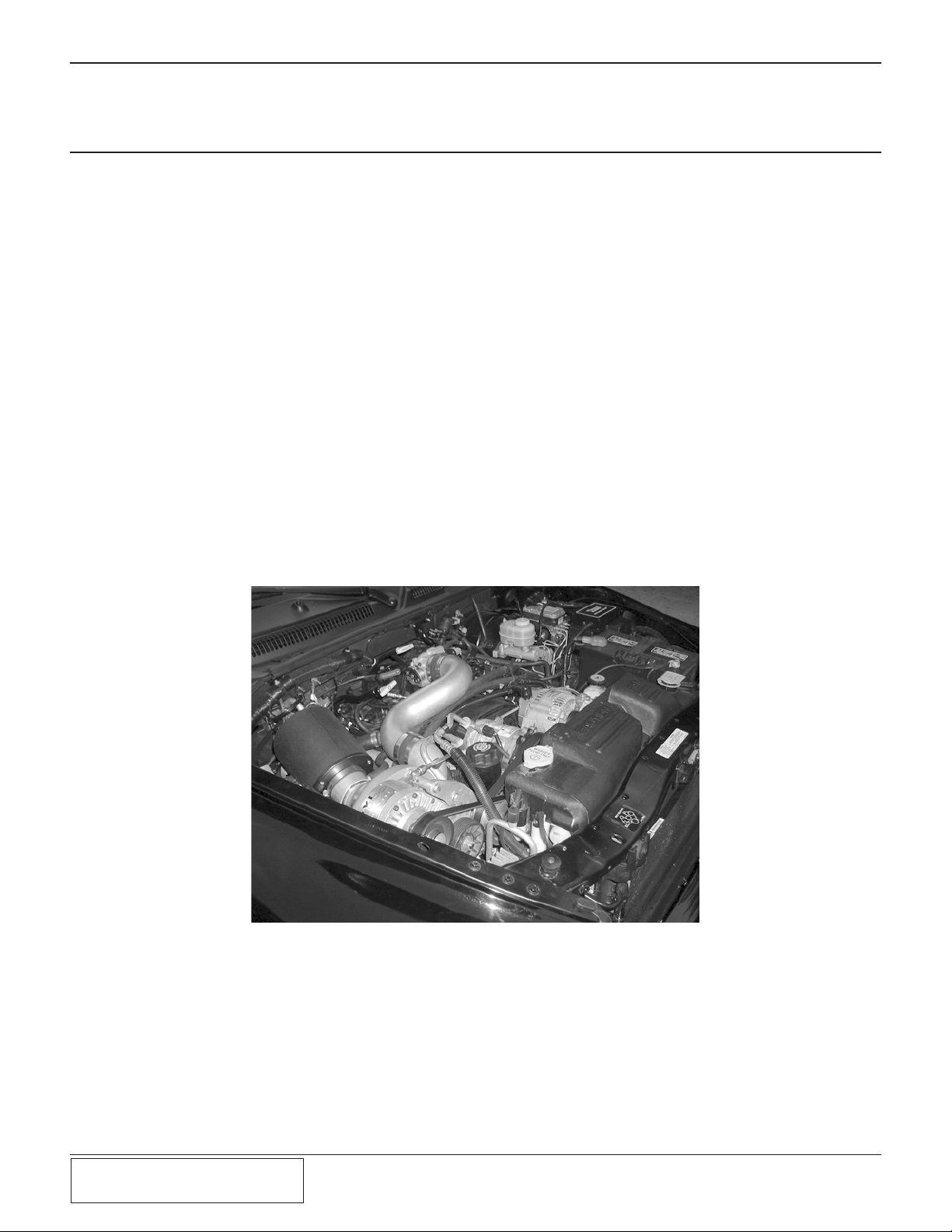
B
egin the initial preparation and disassembly
process by disconnecting the battery cables.
2.1 FAN AND FAN SHROUD REMOVAL
a. Remove the plastic panel under the front of
the vehicle by prying out the seven plastic
clips. Drain the radiator.
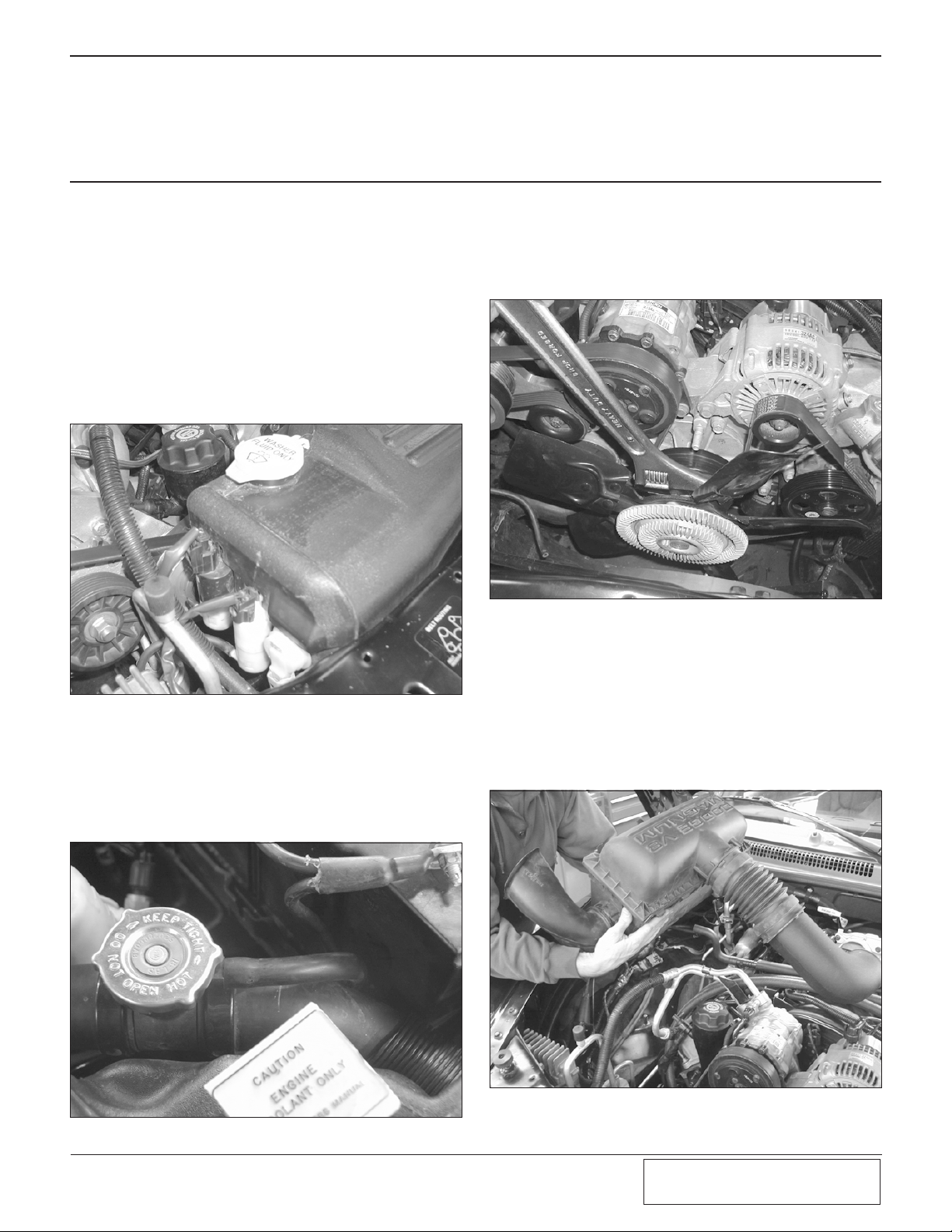
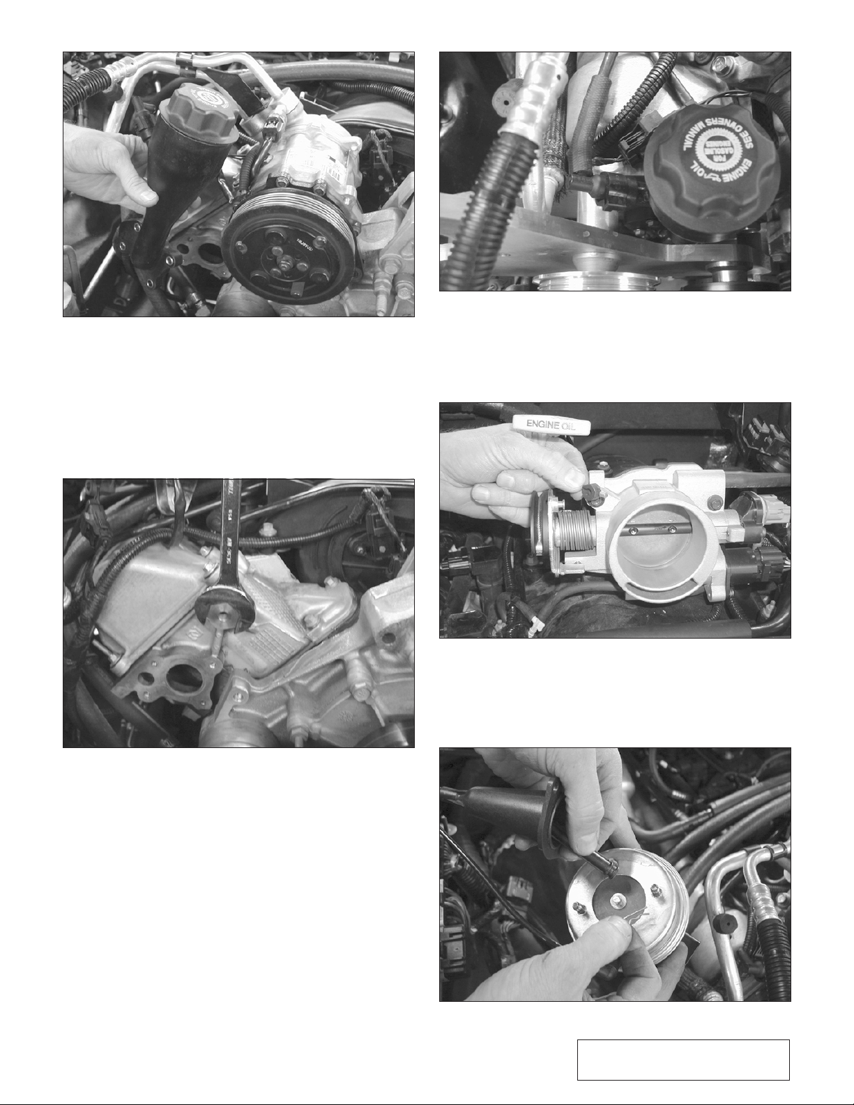
b. Remove the upper fan shroud/reservoir by
first disconnecting the three elctrical plugs
and two small hoses on the passenger side.
(See Fig 2.1.)
Fig. 2-1
c. Disconnect the coolant overflow hose at the
filler cap.
(See Fig. 2-2.) Make sure to
clamp or plug this hose to avoid coollant
loss. Remove the two bolts securing the
shroud using a 10mm socket. Lift up and
remove shroud.
Fig. 2-2
d. Remove the fan using a 36mm or a large
crescent wrench. Hitting the wrench with a
brass hammer will break it loose. The fan
unscrews counter-clockwise as viewed from
the front of the engine. (See Fig. 2-3.)
Fig. 2-3
2.2 AIR FILTER REMOVAL
Fig. 2-4
e. Remove the air filter assembly (See Fig. 2-
4). by first loosening the clamp at the throt-
tle body, then disconnect the “S” shaped pcv
hose. (See Fig. 2-5.) Remove the nut securing rear of air box using a 10mm socket.
Lift assembly up and off the rubber mounts.
2-2
P/N: 4809632
©2002 Paxton Automotive
All Rights Reserved, Intl. Copr. Secured
25SEP02 v1.0 Dodge Durango(4809632v1.0)
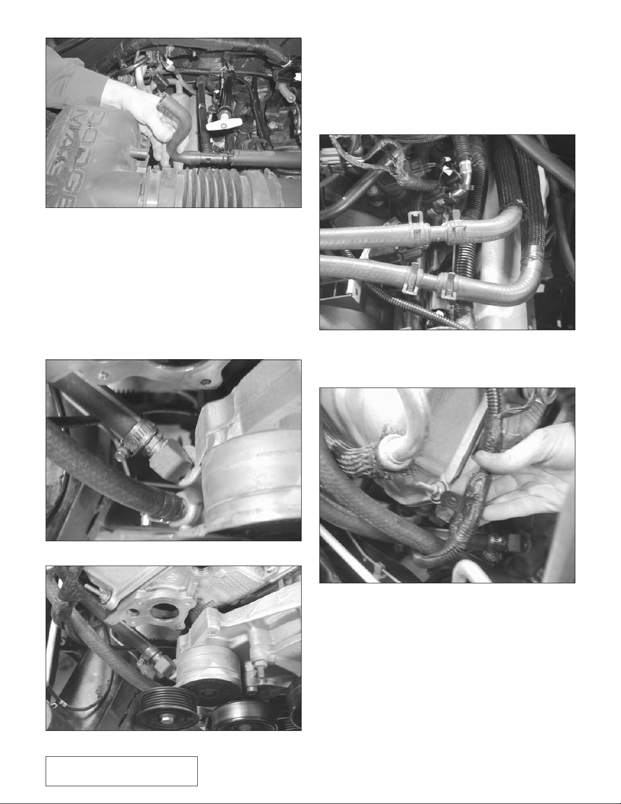
f. Remove both metal coolant lines and their
mounts that run across the top of the engine.
g. On the passenger side of the engine, remove
the uppermost hose fitting that was connected to the coolant hose using a 3/4” wrench.
h. Using Teflon sealant, install the supplied 45
deg. brass fitting so it points back and up
slightly. Thread the straight hose fitting into
this using Teflon sealant. (See Figs. 2-6,
2-7.)
Fig. 2-5
Fig. 2-6
Fig. 2-7
i. Attach the supplied coolant hoses being
careful to get the orientation correct. If necessary, hold the original metal lines in place
to see which hose goes with what fitting.
Re-use the factory spring type clamps
removed from both ends of the original
metal lines at the splice point. (See Fig.
2-8.)
Fig. 2-8
j. Detach wiring harness from the front of the
engine. (See Fig. 2-9.)
Fig. 2-9
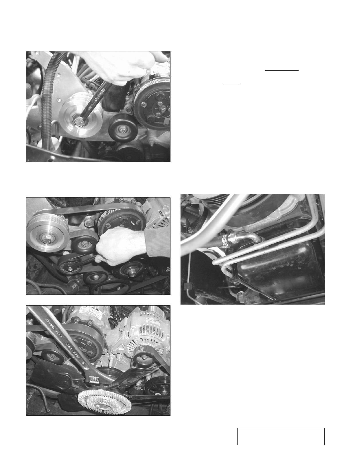
k. Remove the fan belt by rotating the tension-
er using a 15mm wrench or socket.
l. Remove the four bolts securing the oil filler
neck using a 10mm deep socket. (See Fig.
2-10.)
2-3
P/N: 4809632
©2002 Paxton Automotive
All Rights Reserved, Intl. Copr. Secured
25SEP02 v1.0 Dodge Durango(4809632v1.0)
Fig. 2-10
m. Remove the three bolts securing the A/C
compressor using a 13mm and 15mm socket. Lift compressor up and let it rest on top
of the valve cover.
n. Using a 1-1/8” wrench or socket, remove the
large bolt on the front of the cylinder head.
(See Fig. 2-11.)
Fig. 2-11
o. Trim the plastic hose that connects to the oil
filler by cutting it off just before the second
barb (approx 3/4”). Do not remove the second barb as this keeps the hose from coming
off under boost. (See Fig. 2-12.) Install the
supplied longer hose.
Fig. 2-12
p. Detach the cruise control cable at the throttle
body. (See Fig. 2-13.) Using a 10mm socket,
unbolt the cruise control actuator and seperate it from its mounting bracket.
Fig. 2-13
Fig. 2-14
q. Once you have removed the two 10mm nuts
securing the cable to the actuator, pull out
the small pin using a pair of pliers. (See Fig.
2-14.)

2-4
P/N: 4809632
©2002 Paxton Automotive
All Rights Reserved, Intl. Copr. Secured
25SEP02 v1.0 Dodge Durango(4809632v1.0)
r. Re-route the cruise control cable behind the
A/C lines at the firewall. Unbolt the computer from the inner fender panel using an 8mm
socket and route the cruise control cable
behind it. (See Fig. 2-15.)
Fig. 2-15
s. Re-assemble the actuator onto the new bracket.
(See Fig. 2-16.)
Fig. 2-16
t. Bolt the bracket to the fender panel using
the two existing holes next to the large
opening. The plug portion should point
straight down. Re-attach the cable at the
throttle body. Re-attach the computer.
u. Attach the rear support plate to the cylinder
head using the supplied large bolt.
(See Figure
2-17)
Use at least two of the supplied 6mm
bolts to align the bracket with the other
mounting holes before tightening. Make sure
the supplied O-ring is in place on the rear of
the plate.
Fig. 2-17
v. Bolt the oil filler neck to the plate using the
supplied hardware. (See Fig. 2-18.) Reattach the PCV hose.
Fig. 2-18
w. Bolt the A/C Compressor back in place
using the original hardware. You may need
to bend the A/C line slightly to fit in corner
of plate. (See Fig. 2-19.)
Fig. 2-19
A/C COMPRESSOR
A/C LINE
2-5
P/N: 4809632
©2002 Paxton Automotive
All Rights Reserved, Intl. Copr. Secured
25SEP02 v1.0 Dodge Durango(4809632v1.0)
x. Bolt the front plate to the rear plate using a
9/16”, 3/4” and a 17mm socket (See Fig.
2-20.) Check the tightness of the small idler
attached to the plate with a 9/16” socket.
Fig. 2-20
y. Install the new Accessory drive belt. (See
Fig. 2-21.) Re-install the fan. (See Fig.
2-22.)
Fig. 2-21
Fig. 2-22
z. From under the vehicle mark and drill the
oil pan in preparation for the oil drain. (See
Fig. 2-23.) On the front of the pan, measure
and mark the center. Now find the centerpoint between the pan rail. Coat a 3/16” drill
bit with grease and drill the hole. Coat the
supplied punch with anti-seize or heavy
grease and drive it in only halfway using an
air chisel with a blunt tip. Do not use a hammer. Do not go in all the way or you will
damage internal engine components. Now
you must cut off the front portion of the
hardened steel punch with either a grinder or
a cut off wheel. Continue driving the punch
in, and expand the hole until it measures
Ø9/16". Go slow with this. It will affect
your tapped hole if you go too far. Now tap
the hole using a greased 3/8 NPT tap. Go
slowly and make sure the tap goes in
straight. Stop periodically to clean and regrease the tap. Run the tap in only 2/3 of the
way and check to see that the fitting will
screw in leaving at least three threads
exposed. Clean threads thoroughly, coat fitting with Teflon sealant and install.
Fig. 2-23
 Loading...