

Page 1

DR DIFFERENTIAL & DRIVELINE 3 - 1
DIFFERENTIAL & DRIVELINE
TABLE OF CONTENTS
page page
PROPELLER SHAFT ......................1
HALF SHAFT ...........................11
FRONT AXLE - C205F ....................18
FRONT AXLE - 9 1/4 AA ...................45
PROPELLER SHAFT
TABLE OF CONTENTS
page page
PROPELLER SHAFT
DIAGNOSIS AND TESTING ................1
STANDARD PROCEDURE .................3
SPECIFICATIONS ........................6
SPECIAL TOOLS ........................6
FRONT PROPELLER SHAFT
REMOVAL .............................6
INSTALLATION ..........................7
REAR PROPELLER SHAFT
REMOVAL .............................7
REAR AXLE-91/4 .......................69
REAR AXLE - 10 1/2 AA ..................100
REAR AXLE - 11 1/2 AA ..................127
INSTALLATION ..........................8
CENTER BEARING
REMOVAL .............................8
INSTALLATION ..........................8
ADJUSTMENTS .........................8
SINGLE CARDAN UNIVERSAL JOINTS
DISASSEMBLY ..........................9
ASSEMBLY .............................9
PROPELLER SHAFT
DIAGNOSIS AND TESTING
PROPELLER SHAFT VIBRATION
Tires that are out-of-round or wheels that are
unbalanced, will cause a low frequency vibration.
Brake drums that are unbalanced will cause a
harsh, low frequency vibration.
Driveline vibration can also result from loose or
damaged engine mounts.
Propeller shaft vibration increases as the vehicle
speed is increased. A vibration that occurs within a
specific speed range is not usually caused by a propeller shaft being unbalanced. Defective universal
joints or an incorrect propeller shaft angle are usually the cause of such a vibration.
Page 2
3 - 2 PROPELLER SHAFT DR
PROPELLER SHAFT (Continued)
DRIVELINE VIBRATION
Drive Condition Possible Cause Correction
Propeller Shaft Noise 1) Undercoating or other foreign
material on shaft.
2) Loose U-joint clamp screws. 2) Install new clamps and screws
3) Loose or bent U-joint yoke or
excessive runout.
4) Incorrect driveline angularity. 4) Measure and correct driveline
5) Rear spring center bolt not in
seat.
6) Worn U-joint bearings. 6) Install new U-joint.
7) Propeller shaft damaged or out
of balance.
8) Broken rear spring. 8) Install new rear spring.
9) Excessive runout or unbalanced
condition.
10) Excessive drive pinion gear
shaft runout.
11) Excessive axle yoke deflection. 11) Inspect and replace yoke if
12) Excessive transfer case runout. 12) Inspect and repair as necessary.
1) Clean exterior of shaft and wash
with solvent.
and tighten to proper torque.
3) Install new yoke.
angles.
5) Loosen spring u-bolts and seat
center bolt.
7) Installl new propeller shaft.
9) Re-index propeller shaft, test,
and evaluate.
10) Re-index propeller shaft and
evaluate.
necessary.
Universal Joint Noise 1) Loose U-joint clamp screws. 1) Install new clamps and screws
and tighten to proper torque.
2) Lack of lubrication. 2) Replace as U-joints as
necessary.
PROPELLER SHAFT BALANCE
NOTE: Removing and re-indexing the propeller
shaft 180° relative to the yoke may eliminate some
vibrations.
If propeller shaft is suspected of being unbalanced,
it can be verified with the following procedure:
(1) Raise the vehicle.
(2) Clean all the foreign material from the propel-
ler shaft and the universal joints.
(3) Inspect the propeller shaft for missing balance
weights, broken welds, and bent areas. If the pro-
peller shaft is bent, it must be replaced.
(4) Inspect the universal joints to ensure that they
are not worn, are properly installed, and are correctly aligned with the shaft.
(5) Check the universal joint clamp screws torque.
(6) Remove the wheels and tires. Install the wheel
lug nuts to retain the brake drums or rotors.
(7) Mark and number the shaft six inches from the
yoke end at four positions 90° apart.
(8) Run and accelerate the vehicle until vibration
occurs. Note the intensity and speed the vibration
occurred. Stop the engine.
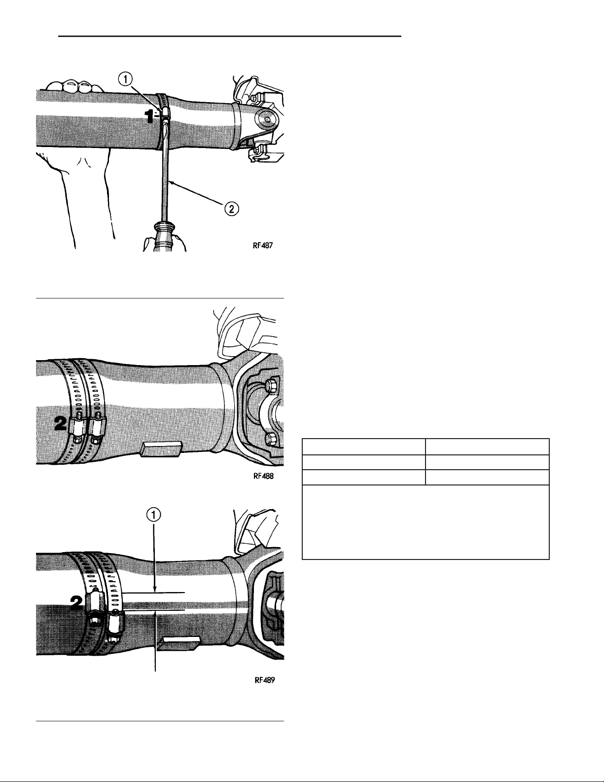
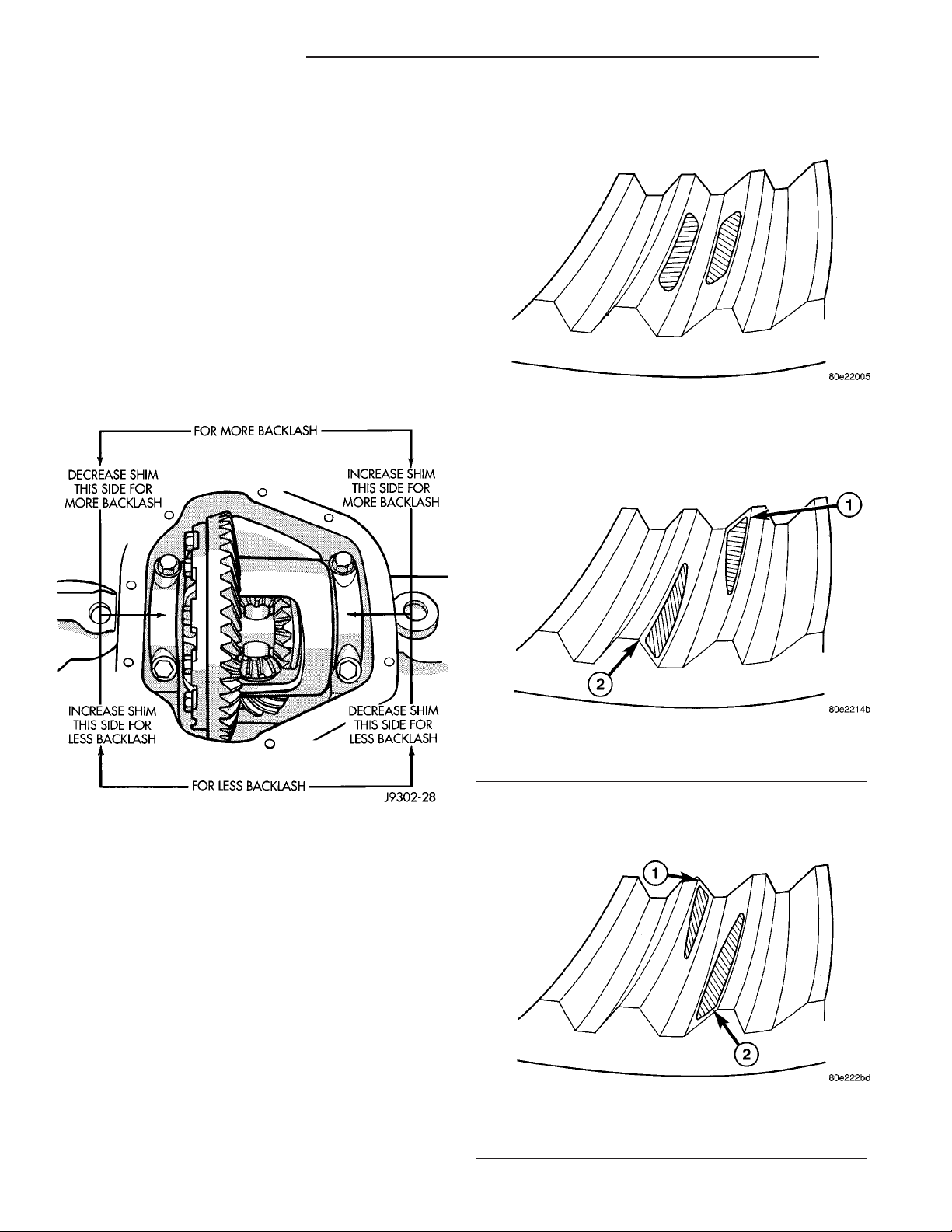
(9) Install a screw clamp at position 1 (Fig. 1).
(10) Start the engine and re-check for vibration. If
there is little or no change in vibration, move the
clamp to one of the other three positions. Repeat the
vibration test.
(11) If there is no difference in vibration at the
other positions, the source of the vibration may not
be propeller shaft.
(12) If the vibration decreased, install a second
clamp (Fig. 2) and repeat the test.
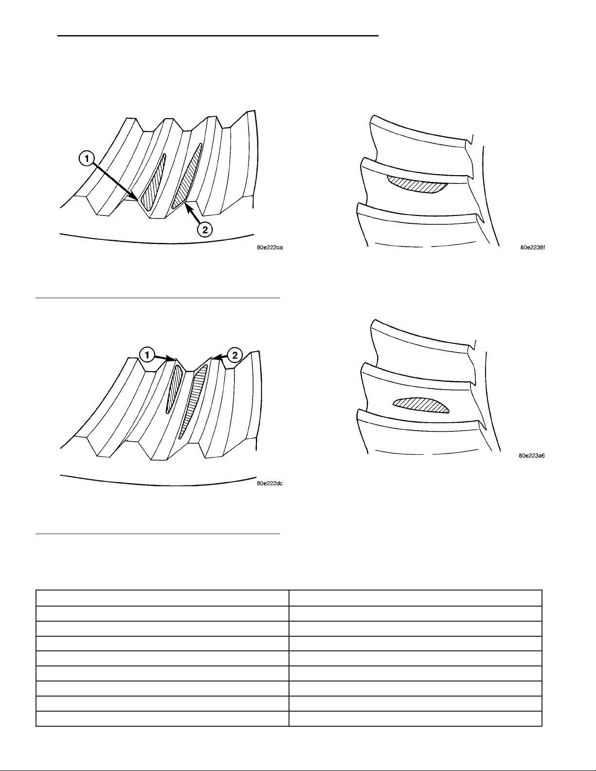
(13) If the additional clamp causes an additional
vibration, separate the clamps (1/2 inch above and
below the mark). Repeat the vibration test (Fig. 3).
(14) Increase distance between the clamp screws
and repeat the test until the amount of vibration is
at the lowest level. Bend the slack end of the clamps
so the screws will not loosen.
Page 3
DR PROPELLER SHAFT 3 - 3
PROPELLER SHAFT (Continued)
(15) If the vibration remains unacceptable, apply
the same steps to the front end of the propeller shaft.
(16) Install the wheel and tires. Lower the vehicle.
PROPELLER SHAFT RUNOUT
(1) Remove dirt, rust, paint and undercoating from
the propeller shaft surface where the dial indicator
will contact the shaft.
(2) The dial indicator must be installed perpendicular to the shaft surface.
(3) Measure runout at the center and ends of the
shaft sufficiently far away from weld areas to ensure
that the effects of the weld process will not enter into
the measurements.
(4) Refer to Runout Specifications chart.
(5) If the propeller shaft runout is out of specifica-
Fig. 1 CLAMP SCREW AT POSITION 1
1 - CLAMP
2 - SCREWDRIVER
tion, remove the propeller shaft, index the shaft 180°,
and re-install the propeller shaft. Measure shaft
runout again.
(6) If the propeller shaft runout is now within
specifications, mark the shaft and yokes for proper
orientation.
(7) If the propeller shaft runout is not within specifications, verify that the runout of the transmission/
transfer case and axle are within specifications.
Correct as necessary and re-measure propeller shaft
runout.
(8) Replace the propeller shaft if the runout still
exceeds the limits.
RUNOUT SPECIFICATIONS
1-1⁄2INCH
Fig. 2 TWO CLAMP SCREWS
Fig. 3 CLAMP SCREWS SEPARATED
Front of Shaft 0.020 in. (0.50 mm)
Center of Shaft 0.025 in. (0.63 mm)
Rear of Shaft 0.020 in. (0.50 mm)
note:
Measure front/rear runout approximately 3 inches (76
mm) from the weld seam at each end of the shaft
tube for tube lengths over 30 inches. For tube lengths
under 30 inches, the maximum allowed runout is
0.020 in. (0.50 mm) for the full length of the tube.
STANDARD PROCEDURE
PROPELLER SHAFT ANGLE
This procedure applies to both the front/rear propeller shafts. To obtain the front output angle (A) on
the front propeller shaft, place the inclinometer the
machined surface of the C/V joint.
(1) To check driveline alignment, raise and support
the vehicle at the axles as level as possible. Allow the
wheels and propeller shaft to turn.
(2) Remove any external bearing snap rings, if
equipped from universal joint so protractor base sits
flat.
Page 4
3 - 4 PROPELLER SHAFT DR
PROPELLER SHAFT (Continued)
(3) Rotate the shaft until transmission/transfer
case output yoke bearing is facing downward.
NOTE: Always make measurements from front to
rear and from the same side of the vehicle.
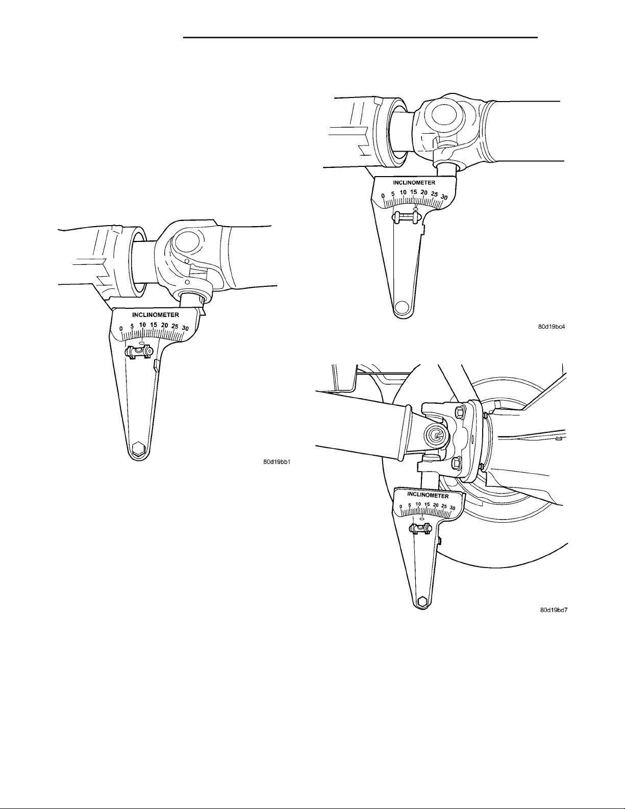
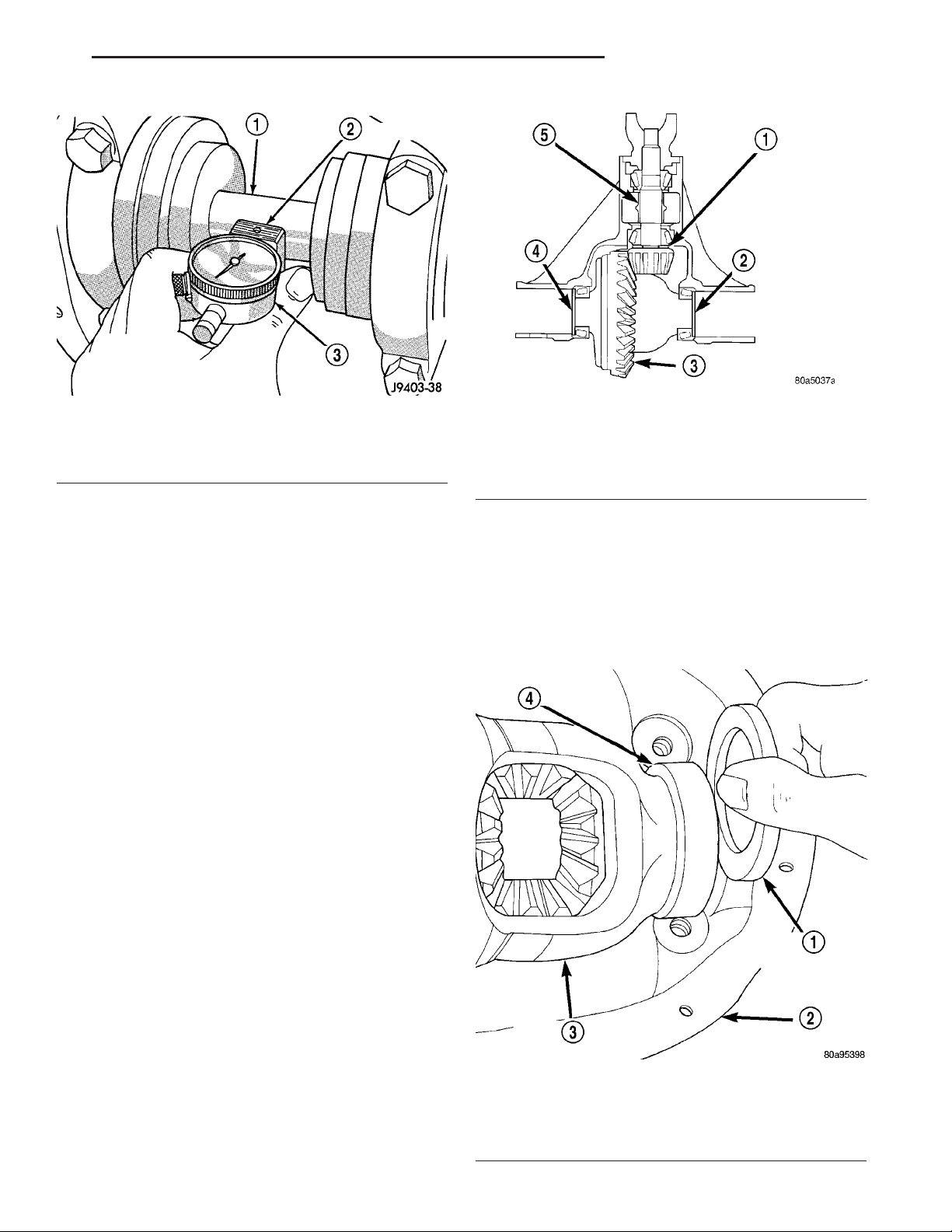
(4) Place Inclinometer 7663 on yoke bearing (A)
parallel to the shaft (Fig. 4). Center bubble in sight
glass and record measurement.
This measurement will give you the transmission yoke Output Angle (A).
Fig. 4 OUTPUT ANGLE (A)
(5) Rotate propeller shaft 90 degrees and place
Inclinometer on yoke bearing parallel to the shaft
(Fig. 5). Center bubble in sight glass and record measurement. This measurement can also be taken at
the rear end of the shaft.
This measurement will give you the Propeller
Shaft Angle (C).
(6) Rotate propeller shaft 90 degrees and place
Inclinometer on companion flange yoke bearing parallel to the shaft (Fig. 6). Center bubble in sight glass
and record measurement.
This measurement will give you the pinion
Companion Flange Input Angle (B).
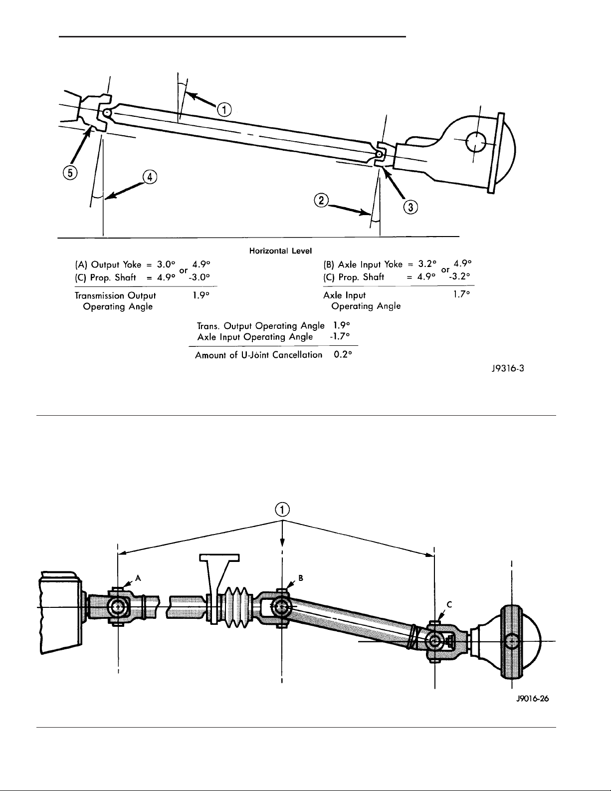
(7) Subtract smaller figure from larger (C minus
A) to obtain Transmission/Transfer Case Output
Operating Angle.
(8) Subtract smaller figure from larger (C minus
B) to obtain axle Input Operating Angle.
Fig. 5 PROPELLER SHAFT ANGLE (C)
Fig. 6 INPUT ANGLE (B)
Refer to rules given below and the example in (Fig.
7) for additional information.
• Good cancellation of U-joint operating angles
should be within 1°.
• Operating angles should be less than 3°.
• At least 1/2 of one degree continuous operating
(propeller shaft) angle.
Page 5
DR PROPELLER SHAFT 3 - 5
PROPELLER SHAFT (Continued)
Fig. 7 UNIVERSAL JOINT ANGLE EXAMPLE
1 - 4.9°Angle (C)
2 - 3.2°Angle (B)
3 - Input Yoke
TWO-PIECE PROPELLER SHAFT
The procedure to measure the propeller shaft
angles involved with a two-piece (Fig. 8) propeller
shaft is the same as those for a one-piece propeller
shaft.
4 - 3.0°Angle (A)
5 - Output Yoke
1 - YOKES MUST BE IN SAME PLANE
Fig. 8 UNIVERSAL JOINT ANGLE
Page 6
3 - 6 PROPELLER SHAFT DR
PROPELLER SHAFT (Continued)
SPECIFICATIONS
TORQUE SPECIFICATIONS
DESCRIPTION N·m Ft. Lbs. In. Lbs.
Center Bearing Bolts 54 40 -
Front Pinion Flange Bolts 115 85 -
Rear Pinion Flange Bolts 115 85 -
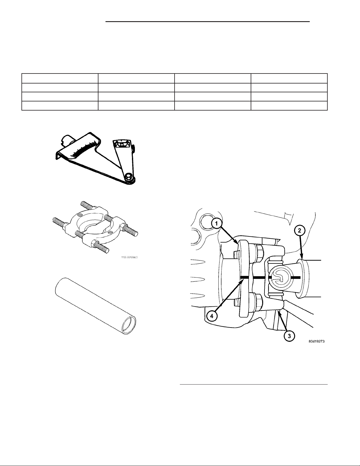
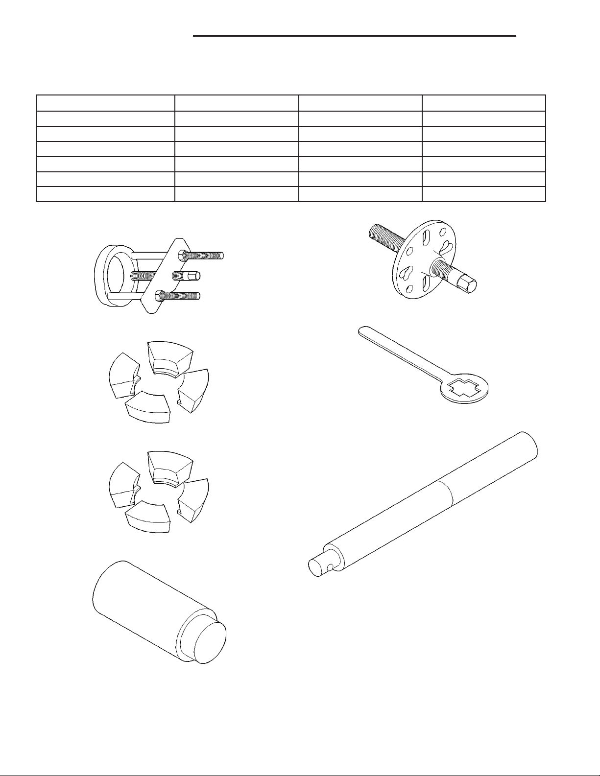
SPECIAL TOOLS
INCLINOMETER 7663
Bearing Splitter 1130
FRONT PROPELLER SHAFT
REMOVAL
(1) Position transmission and transfer case into
neutral.
(2) Raise and support vehicle.
(3) Remove exhaust crossover pipe.
(4) Mark a line across the axle companion flange
and propeller shaft flange yoke (Fig. 9) for installation reference.
INSTALLER 6052
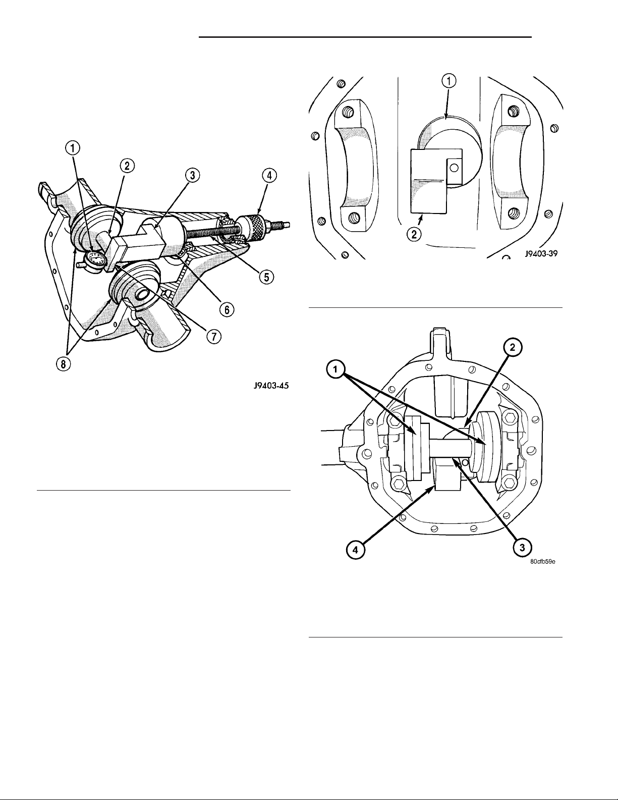
Fig. 9 COMPANION FLANGE
1 - COMPANION FLANGE
2 - PROPELLER SHAFT
3 - FLANGE YOKE
4 - REFERENCE MARK
(5) Remove companion flange bolts.
(6) Remove dust boot clamp (Fig. 10) from the C/V
jonit end of the shaft.
(7) Remove propeller shaft.
Page 7
DR PROPELLER SHAFT 3 - 7
FRONT PROPELLER SHAFT (Continued)
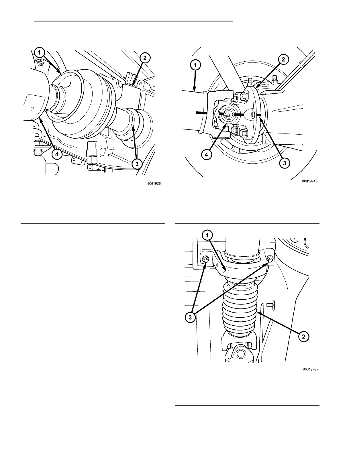
Fig. 10 DUST BOOT
1 - C/V JOINT
2 - TRANSFER CASE
3 - BOOT CLAMP
4 - PROPELLER SHAFT
INSTALLATION
(1) Install propeller shaft with with all reference
marks aligned.
(2) Install transfer case companion flange bolts
and tighten to 30.5 N·m (22.5 ft. lbs.).
(3) Install axle companion flange bolts and tighten
to 108 N·m (80 ft. lbs.).
(4) Install skid plate, if equipped.
(5) Lower vehicle and road test to verify repair.
REAR PROPELLER SHAFT
REMOVAL
(1) Shift transmission into Neutral.
(2) Raise and support vehicle.
(3) Mark a line across the pinion companion flange
and propeller shaft flange yoke (Fig. 11) for installation reference.
(4) Mark the outline of the center bearing (Fig. 12)
on the crossmember for installation reference, if
equipped.
(5) Remove center bearing mounting nuts, if
equipped.
(6) Remove pinion yoke companion flange bolts.
(7) Slide slip yoke off of the transmission or transfer case output shaft and remove propeller shaft.
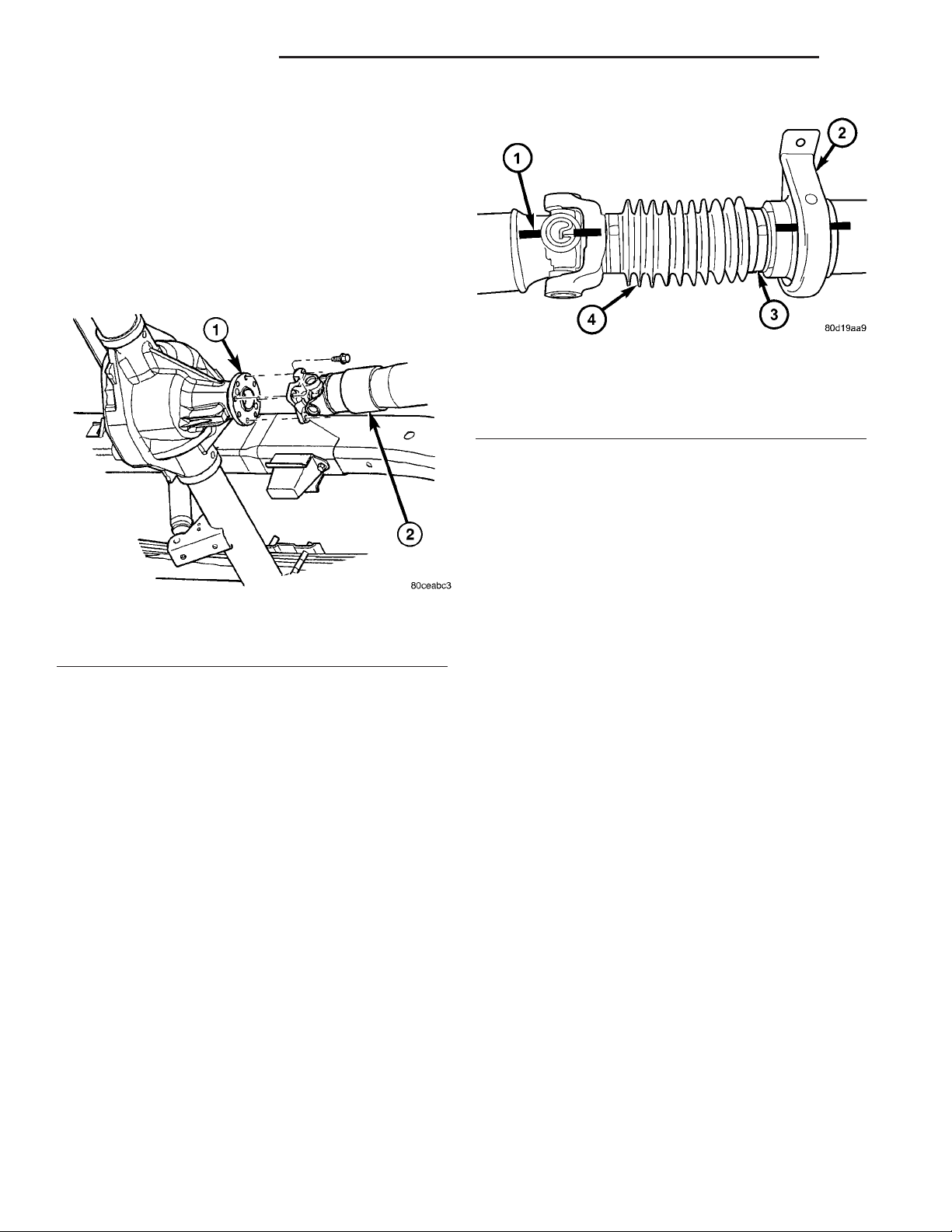
Fig. 11 COMPANION FLANGE
1 - PROPELLER SHAFT
2 - COMPANION FLANGE
3 - REFERENCE MARK
4 - SHAFT FLANGE YOKE
Fig. 12 CENTER BEARING
1 - CENTER BEARING
2 - DUST BOOT
3 - MOUNTING NUTS
Page 8
3 - 8 PROPELLER SHAFT DR
REAR PROPELLER SHAFT (Continued)
INSTALLATION
(1) Slide the slip yoke onto the transmission/transfer case output shaft.
(2) Align and install center bearing on crossmember, if necessary and tighten nutts to 54 N·m (40 ft.
lbs.).
(3) Align reference marks on the propeller shaft
yoke and pinion companion flange (Fig. 13).
(4) Tighten pinion companion flange bolts to 115
N·m (85 ft. lbs.).
Fig. 14 REFERENCE MARKS
1 - REFERENCE MARK
2 - CENTER BEARING
3 - BOOT CLAMP
4 - DUST BOOT
INSTALLATION
NOTE: Two types of center bearings are used and
are not interchangeable. Install the same type as
the vehicle was built with.
Fig. 13 REAR PROPELLER SHAFT
1 - COMPANION FLANGE
2 - PROPELLER SHAFT
(5) Lower the vehicle.
CENTER BEARING
REMOVAL
(1) Remove rear propeller shaft.
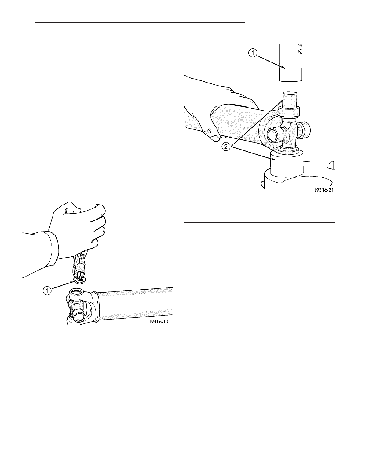
(2) Mark the two shafts (Fig. 14) for installation
reference.
(3) Remove slip joint boot clamp and separate the
two shafts.
(4) Use hammer and punch to tap slinger away
from shaft to provide room for bearing splitter.
(5) Position Bearing Splitter Tool 1130 between
slinger and shaft.
CAUTION: Do not damage shaft spline during
removal of center bearing.
(6) Set shaft in press and press bearing off the
shaft.
(1) Install new slinger on shaft and drive into posi-
tion with appropriate installer tool.
(2) Install new center bearing on shaft with Bearing Installer Tool 6052. Drive on shaft with hammer
until bearing is seated.
(3) Clean shaft splines and apply a coat of multipurpose grease.
(4) Align master splines and slide front and rear
half-shafts together. Reposition slip yoke boot and
install new clamp.
(5) Install propeller shaft in vehicle.
ADJUSTMENTS
CENTER BEARING
Launch shudder is a vibration that occurs at first
acceleration from a stop. Shudder vibration usually
peaks at the engines highest torque output. Shudder
is a symptom associated with vehicles using a twopiece propeller shaft. To decrease shudder, lower the
center bearing in 1/8 inch increments. Use shim
stock or fabricated plates. Plate stock must be used
to maintain compression of the rubber insulator
around the bearing. Do not use washers. Replace the
original bolts with the appropriate increased length
bolts.
Page 9
DR PROPELLER SHAFT 3 - 9
SINGLE CARDAN UNIVERSAL
JOINTS
DISASSEMBLY
NOTE: The following procedure is described for a
propeller shaft equipped with only a cardan joint in
the tube yoke. If the propeller shaft is equipped
with a companion yoke, simply repeat the following
steps to remove the cardan joint from the companion yoke after removing the cardan joint from the
tube yoke.
Individual components of cardan universal joints
are not serviceable. If worn or leaking, they must be
replaced as an assembly.
(1) Remove the propeller shaft.
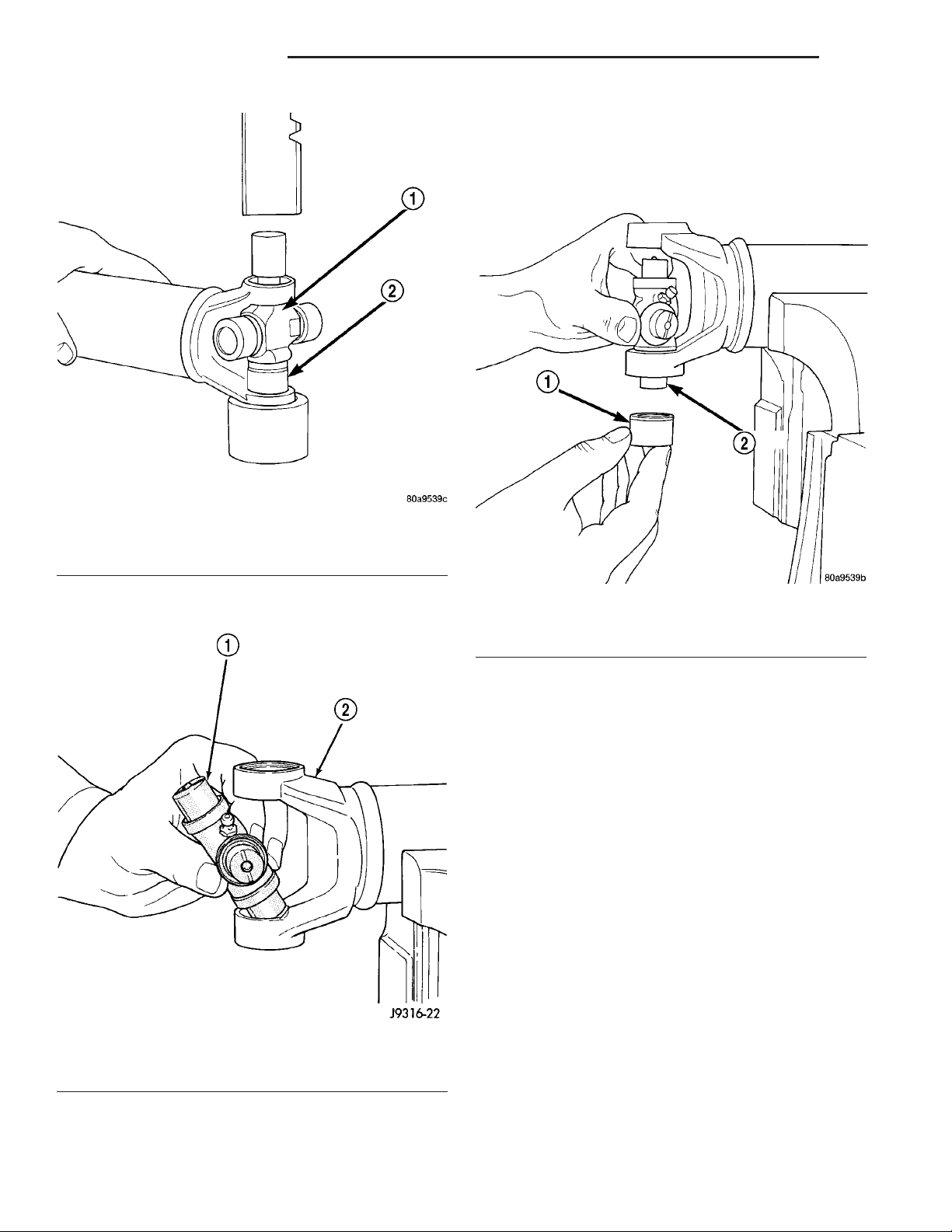
(2) Using a soft drift, tap the outside of the bearing cap assembly to loosen snap ring.
(3) Remove snap rings from both sides of yoke
(Fig. 15).
Fig. 16 Press Out Bearing
1 - PRESS
2 - SOCKET
Fig. 15 Snap Ring
1 - SNAP RING
(4) Set the yoke in an arbor press or vise with a
socket whose inside diameter is large enough to
receive the bearing cap positioned beneath the yoke.
(5) Position the yoke with the grease fitting, if
equipped, pointing up.
(6) Place a socket with an outside diameter
smaller than the upper bearing cap on the upper
bearing cap and press the cap through the yoke to
release the lower bearing cap (Fig. 16).
(7) If the bearing cap will not pull out of the yoke
by hand after pressing, tap the yoke ear near the
bearing cap to dislodge the cap.
(8) To remove the opposite bearing cap, turn the
yoke over and straighten the cross in the open hole.
Then, carefully press the end of the cross until the
remaining bearing cap can be removed (Fig. 17).
CAUTION: If the cross or bearing cap are not
straight during installation, the bearing cap will
score the walls of the yoke bore and damage can
occur.
ASSEMBLY
NOTE: The following procedure is described for a
propeller shaft equipped with only a cardan joint in
the tube yoke. If the propeller shaft is equipped
with a companion yoke, simply repeat the following
steps to remove the cardan joint from the companion yoke after removing the cardan joint from the
tube yoke.
(1) Apply extreme pressure (EP) N.L.G.I. Grade 1
or 2 grease to inside of yoke bores to aid in installation.
Page 10
3 - 10 PROPELLER SHAFT DR
SINGLE CARDAN UNIVERSAL JOINTS (Continued)
(3) Place a bearing cap over the trunnion and
align the cap with the yoke bore (Fig. 19). Keep the
needle bearings upright in the bearing assembly. A
needle bearing lying at the bottom of the cap will
prevent proper assembly.
Fig. 17 Press Out Remaining Bearing
1 - CROSS
2 - BEARING CAP
(2) Position the cross in the yoke with its lube fit-
ting, if equipped, pointing up (Fig. 18).
Fig. 19 Install Bearing On Trunnion
1 - BEARING CAP
2 - TRUNNION
(4) Press the bearing cap into the yoke bore
enough to install a snap ring.
(5) Install a snap ring.
(6) Repeat Step 3 and Step 4to install the opposite
bearing cap. If the joint is stiff or binding, strike the
yoke with a soft hammer to seat the needle bearings.
(7) Add grease to lube fitting, if equipped.
(8) Install the propeller shaft.
1 - CROSS
2 - YOKE
Fig. 18 Cross In Yoke
Page 11
DR HALF SHAFT 3 - 11
HALF SHAFT
TABLE OF CONTENTS
page page
HALF SHAFT
CAUTION .............................11
DIAGNOSIS AND TESTING ................11
REMOVAL .............................11
INSTALLATION .........................12
SPECIFICATIONS .......................12
SPECIAL TOOLS .......................12
HALF SHAFT
CAUTION
CAUTION:: Never grasp half shaft assembly by the
boots. This may cause the boot to pucker or crease
and reduce the service life of the boot.
Avoid over angulating or stroking the C/V joints
when handling the half shaft.
Half shafts exposed to battery acid, transmission
fluid, brake fluid, differential fluid or gasoline may
cause the boots to deteriorate.
DIAGNOSIS AND TESTING
Check for grease at the inboard and outboard C/V
joint. This is a sign of boot or boot clamp damage.
NOISE/VIBRATION IN TURNS
A clicking noise or a vibration in turns could be
caused by a damaged outer C/V or inner tripod joint
seal boot or seal boot clamps. This will result in the
loss/contamination of the joint grease, resulting in
inadequate lubrication of the joint. Noise could also
be caused by another component of the vehicle coming in contact with the half shafts.
CV JOINT-OUTER
REMOVAL .............................13
INSTALLATION .........................13
CV JOINT-INNER
REMOVAL .............................16
INSTALLATION .........................16
VIBRATION AT HIGHWAY SPEEDS
This problem could be a result of out of balance
front tires or tire/wheel runout. Foreign material
(mud, etc.) packed on the backside of the wheel(s)
will also cause a vibration.
REMOVAL
(1) Loosen lug nuts and hub nut while the with
the vehicle brakes applied.
(2) Raise and support the vehicle.
(3) Remove wheel and tire assembly
(4) Remove half shaft hub nut.
(5) Remove brake caliper and rotor.
(6) Position hydraulic jack under lower suspension
arm and raise jack to unload rebound bumper.
(7) Remove lower shock absorber bolt.
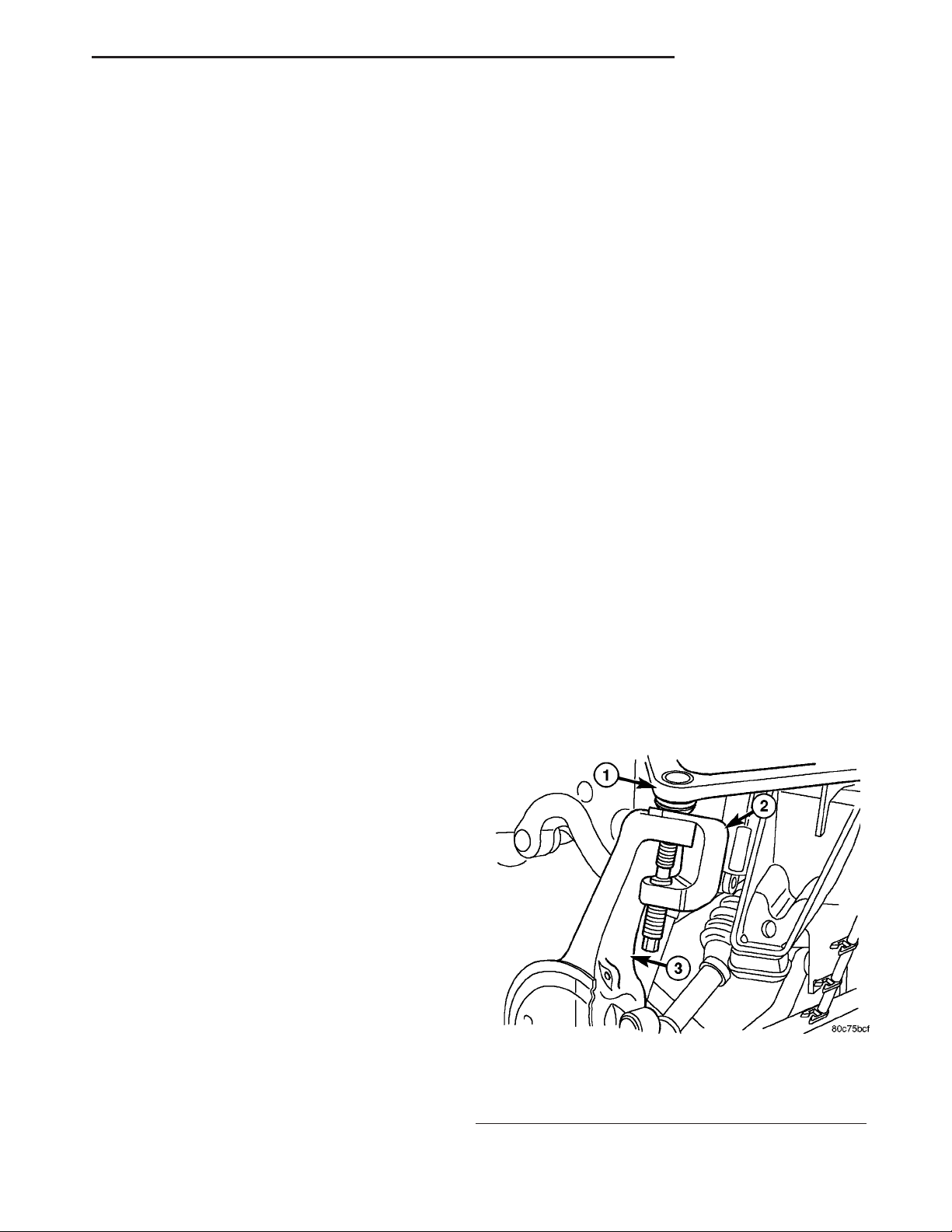
(8) Remove upper ball joint nut and seperate ball
with Remover 8677 (Fig. 1).
CLUNKING NOISE DURING ACCELERATION
This noise may be a result of a damaged or worn
C/V joint. A torn boot or loose/missing clamp on the
inner/outer joint which has allowed the grease to be
lost will damage the C/V joint.
SHUDDER/VIBRATION DURING ACCELERATION
This problem could be a result of a worn/damaged
inner tripod joint or a sticking tripod joint. Improper
wheel alignment may also cause a shudder or vibration.
Fig. 1 UPPER BALL JOINT SEPARATION
1 - UPPER CONTROL ARM
2 - REMOVER
3 - STEERING KNUCKLE
Page 12
3 - 12 HALF SHAFT DR
HALF SHAFT (Continued)
(9) Disengage inner C/V joint from the axle shaft
snap-ring by apply pressure with two pry bars
between the C/V housing and axle housing.
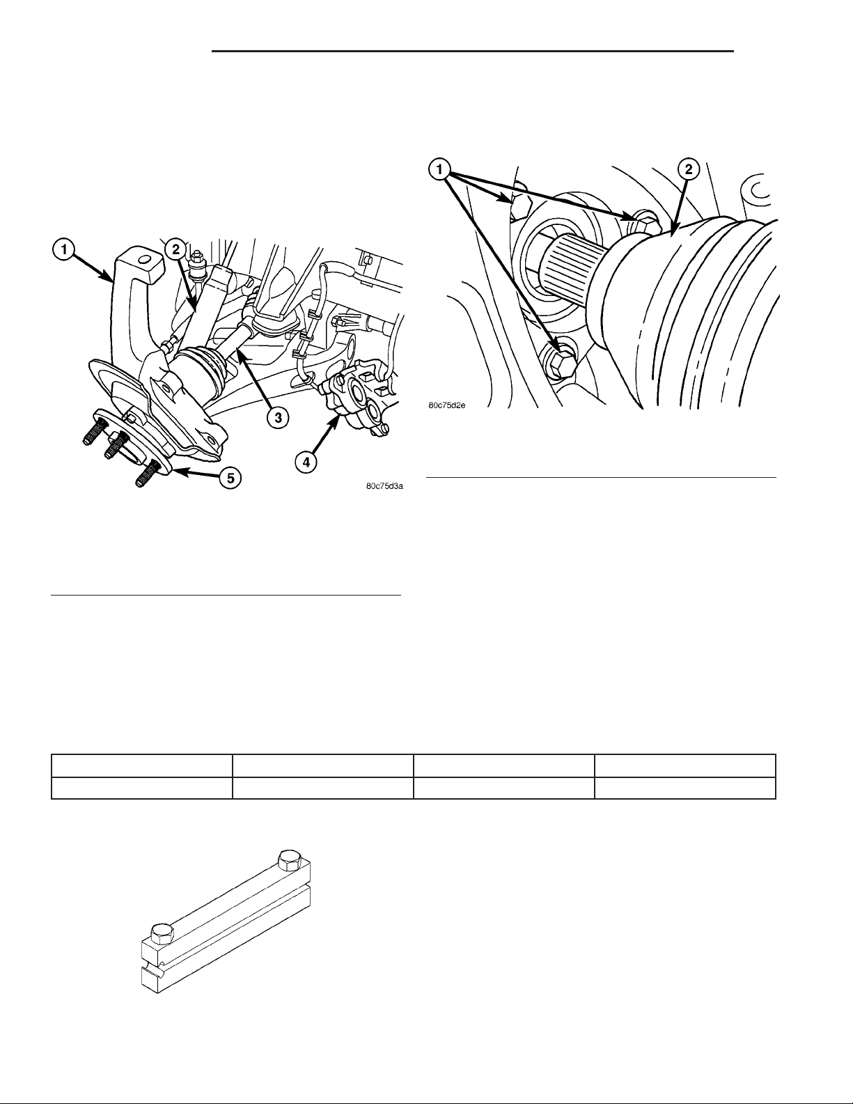
(10) Tilt the knuckle out and push the half shaft
out of the knuckle (Fig. 2).
CAUTION: Do not damage outer C/V threads while
removing half shaft.
Fig. 2 STEERING KNUCKLE
1 - STEERING KNUCKLE
2 - SHOCK
3 - HALFSHAFT
4 - DISC BRAKE CALIPER
5 - HUB/BEARING
(11) Remove the half shaft from the vehicle.
INSTALLATION
(1) Clean hub bearing bore, hub bearing mating
surface and half shaft splines.
(2) Apply a light coating of grease to the front axle
shaft output splines.
(3) Install half shaft into the knuckle (Fig. 3).
Fig. 3 HALF SHAFT AND HUB/BEARING
1 - HUB/BEARING MOUNTING NUTS
2 - HALF SHAFT
(4) Install half shaft on the axle output shaft.
Push firmly to engage the axle output shaft snap
ring into the inner C/V housing.
(5) Install upper ball joint into the knuckle.
(6) Install upper ball joint nut and tighten to specification.
(7) Install lower shock absorber bolt and tighten to
specification.
(8) Install brake rotor and caliper.
(9) Install half shaft hub nut and tighten to 251
N·m (185 ft. lbs.).
(10) Install the wheel and tire assembly.
SPECIFICATIONS
DESCRIPTION N·m Ft. Lbs. In. Lbs.
Half Shaft Nut 251 185 -
SPECIAL TOOLS
CLAMP INSTALLER C-4975A
TORQUE SPECIFICATIONS
Page 13
DR HALF SHAFT 3 - 13
CV JOINT-OUTER
REMOVAL
(1) Clamp shaft in a vise (with soft jaws) and sup-
port C/V joint.
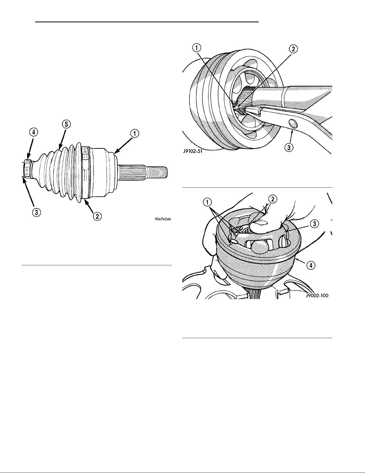
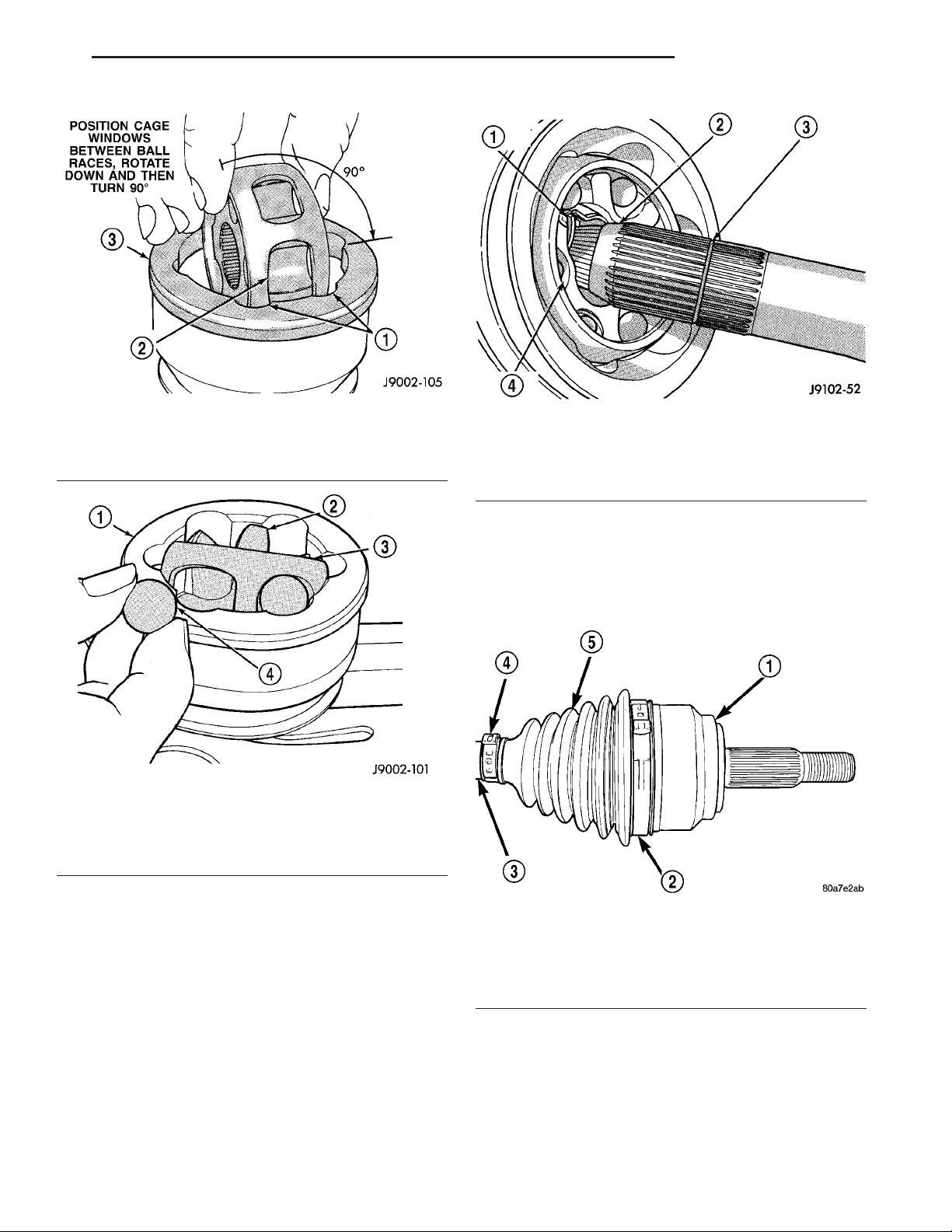
(2) Remove clamps with a cut-off wheel or grinder
(Fig. 4).
CAUTION: Do not damage C/V housing or half
shaft.
Fig. 5 OUTER C/V JOINT
1 - SNAP RING
2 - SNAP RING GROVE
3 - SNAP RING PLIERS
Fig. 4 BOOT CLAMP LOCATIONS
1 - C/V HOUSING
2 - CLAMP
3 - HALF SHAFT
4 - CLAMP
5 - C/V BOOT
(3) Slide the boot down the shaft.
(4) Remove lubricant to expose the C/V joint snap
ring.
(5) Spread snap ring and slide the joint off the
shaft (Fig. 5).
(6) Slide boot off the shaft and discard old boot.
(7) Mark alignment marks on the inner race/hub,
bearing cage and housing with dabs of paint (Fig. 6).
(8) Clamp C/V joint in a vertical position in a soft
jawed vise.
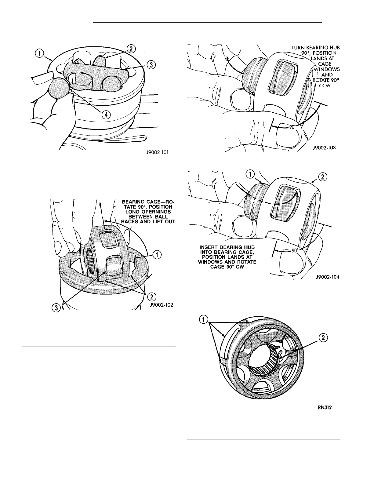
(9) Press down one side of the bearing cage to gain
access to the ball at the opposite side.
NOTE: If joint is tight, use a hammer and brass drift
to loosen the bearing hub. Do not contact the bearing cage with the drift.
(10) Remove ball from the bearing cage (Fig. 7).
(11) Repeat step above until all six balls are
removed from the bearing cage.
(12) Lift cage and inner race upward and out from
the housing (Fig. 8).
(13) Turn inner race 90° in the cage and rotate the
inner race/hub out of the cage (Fig. 9).
Fig. 6 BEARING ACCESS
1 - ALIGNMENT MARKS
2 - BEARING HUB
3 - BEARING CAGE
4 - HOUSING
INSTALLATION
NOTE: If C/V joint is worn, replace entire C/V joint
and boot.
(1) Clean all C/V joint components and shaft.
(2) Apply a light coat of grease supplied with the
joint/boot to the C/V joint components before assembling them.
(3) Align the inner race, cage and housing according to the alignment reference marks.
(4) Insert the inner race into the cage (Fig. 10) and
rotate race into the cage.
(5) Rotate the inner race/hub in the cage (Fig. 11).
Page 14
3 - 14 HALF SHAFT DR
CV JOINT-OUTER (Continued)
1 - HOUSING
2 - INNER RACE/HUB
3 - BEARING CAGE
4 - BALL
Fig. 8 CAGE AND INNER RACE/HUB
1 - HOUSING
2 - INNER RACE
3 - CAGE WINDOW
Fig. 7 BEARING
Fig. 9 INNER RACE/HUB
Fig. 10 INNER RACE/HUB
1 - INNER RACE/HUB
2 - BEARING CAGE
(6) Insert cage into the housing (Fig. 12). Rotate
the cage 90° into the housing so the large bearing
hub counterbore is facing outwards.
(7) Apply the grease supplied with the joint/boot to
the ball races. Spread the grease equally between all
the races.
(8) Tilt inner race/hub and cage and install the
balls (Fig. 13).
(9) Place new clamps onto new boot and slide boot
onto the shaft to it’s original position.
(10) Apply the rest of grease to the C/V joint and
boot.
Fig. 11 CAGE AND INNER RACE/HUB
1 - CAGE WINDOWS
2 - SNAP RING
Page 15
DR HALF SHAFT 3 - 15
CV JOINT-OUTER (Continued)
Fig. 12 BEARING CAGE AND HOUSING
1 - OUTER RACE
2 - BEARING CAGE WINDOW
3 - CV JOINT HOUSING
Fig. 13 BALL BEARING
1 - C/V HOUSING
2 - INNER RACE/HUB
3 - BEARING CAGE
4 - BEARING
Fig. 14 OUTER C/V JOINT
1 - SNAP RING
2 - SHAFT TAPER
3 - SNAP RING GROVE
4 - BEARING HUB
NOTE: Verify boot is not twisted and remove any
excess air.
(13) Secure both boot clamps (Fig. 15) with Clamp
Installer C-4975A. Place tool on clamp bridge and
tighten tool until jaws of the tool are closed.
(11) Install the joint onto the shaft. Push the joint
onto the shaft until the snap ring seats in the groove
(Fig. 14).
NOTE: Pull on the joint to verify the span ring has
engaged.
(12) Position the boot on the joint in it’s original
position.
Fig. 15 BOOT CLAMP LOCATIONS
1 - C/V HOUSING
2 - CLAMP
3 - HALF SHAFT
4 - CLAMP
5 - C/V BOOT
Page 16
3 - 16 HALF SHAFT DR
CV JOINT-INNER
REMOVAL
(1) Clamp shaft in a vise (with soft jaws) and support C/V joint.
(2) Remove clamps with a cut-off wheel or grinder
(Fig. 16).
CAUTION: Do not damage C/V housing or half shaft
with cut-off wheel or grinder.
Fig. 18 TRIPOD SNAP RING
1 - SNAP RING
2 - TRIPOD
3 - PLIERS
(6) Remove tripod and boot from the half shaft.
(7) Clean and inspect C/V components for excessive wear and damage. Replace the tripod as a unit
only if necessary.
Fig. 16 BOOT CLAMP LOCATION
1 - C/V HOUSING
2 - CLAMP
3 - BOOT
4 - CLAMP
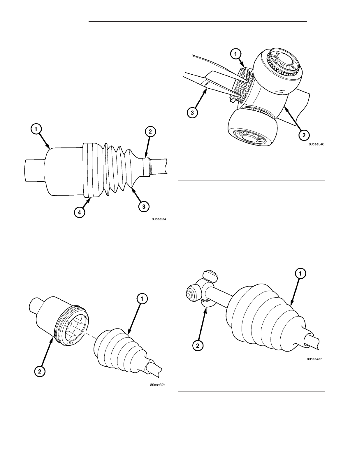
(3) Remove housing from the half shaft (Fig. 17)
and slide boot down shaft.
INSTALLATION
(1) Clean all C/V joint components and shaft.
(2) Slide new boot down the half shaft.
(3) Install tripod and tripod snap ring on the half
shaft (Fig. 19).
Fig. 19 C/V TRIPOD
1 - BOOT
2 - TRIPOD
Fig. 17 C/V HOUSING
1 - BOOT
2 - HOUSING
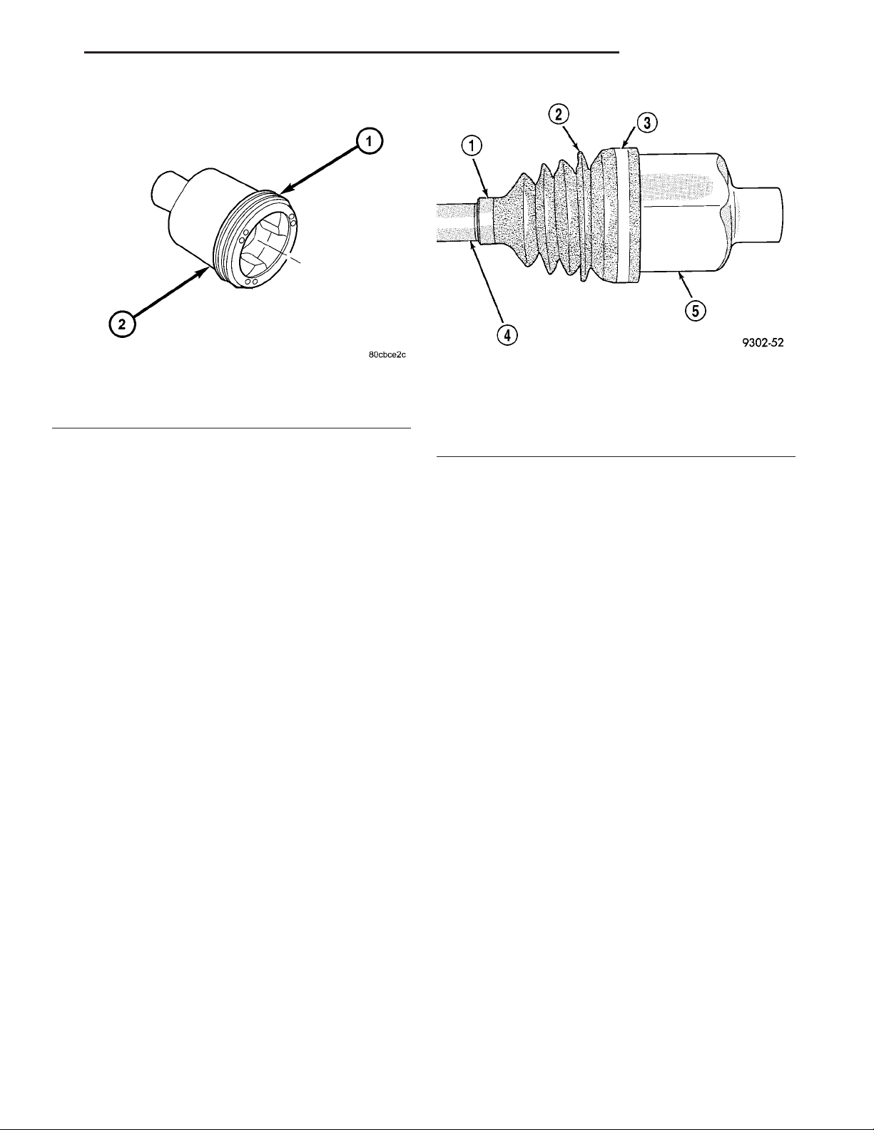
(4) Remove housing bushing from the housing.
(5) Remove tripod snap ring (Fig. 18).
(4) Pack grease supplied with the joint/boot into
the housing and boot.
(5) Coat tripod with supplied grease.
(6) Install new bushing (Fig. 20) onto the housing.
(7) Insert the tripod and shaft in the housing.
Page 17
DR HALF SHAFT 3 - 17
CV JOINT-INNER (Continued)
Fig. 20 HOUSING BUSHING
1 - BUSHING
2 - HOUSING
(8) Position the boot on the joint and shaft in it’s
original position (Fig. 21).
NOTE: Verify boot is not twisted and remove any
excess air.
(9) Measure the distance from the end of the housing to the end of the boot on the shaft. This measurement should be 260 mm (10.25 in.).
Fig. 21 INNER C/V BOOT
1 - CLAMP
2 - BOOT
3 - CLAMP
4 - SHAFT
5 - HOUSING
NOTE: If measurement is not correct, allow more or
less air into the boot.
(10) Secure both boot clamps with Clamp Installer
C-4975A. Place tool on clamp bridge and tighten tool
until the jaws of the tool are closed.
Page 18

3 - 18 FRONT AXLE - C205F DR
FRONT AXLE - C205F
TABLE OF CONTENTS
page page
FRONT AXLE - C205F
DESCRIPTION .........................18
OPERATION ...........................18
DIAGNOSIS AND TESTING ................18
REMOVAL .............................21
INSTALLATION .........................21
ADJUSTMENTS ........................21
SPECIFICATIONS .......................29
SPECIAL TOOLS .......................30
AXLE SHAFTS
REMOVAL .............................33
INSTALLATION .........................33
AXLE SHAFT SEALS
REMOVAL .............................33
INSTALLATION .........................33
AXLE BEARINGS
REMOVAL .............................33
FRONT AXLE - C205F
DESCRIPTION
The axle consists of an alumunum center section
with an axle tube extending from one side. The tube
is pressed into the differential housing. The power is
transferred from the axle through two constant velocity (C/V) drive shafts to the wheel hubs. The drive
shafts are identical and interchangeable.
OPERATION
The axle receives power from the propeller shaft.
The propeller shaft is connected to the pinion gear
which rotates the differential through the gear mesh
with the ring gear bolted to the differential case. The
engine power is transmitted to the axle shafts
through the pinion mate and side gears. The side
gears are splined to the axle shafts.
DIAGNOSIS AND TESTING
GEAR NOISE
Axle gear noise can be caused by insufficient lubricant, incorrect backlash, tooth contact, worn/damaged
gears or the carrier housing not having the proper
offset and squareness.
Gear noise usually happens at a specific speed
range. The noise can also occur during a specific type
of driving condition. These conditions are acceleration, deceleration, coast, or constant load.
INSTALLATION .........................34
PINION SEAL
REMOVAL .............................34
INSTALLATION .........................35
DIFFERENTIAL
DESCRIPTION .........................36
OPERATION ...........................36
REMOVAL .............................36
DISASSEMBLY .........................37
ASSEMBLY ............................38
INSTALLATION .........................38
DIFFERENTIAL CASE BEARINGS
REMOVAL .............................39
INSTALLATION .........................39
PINION GEAR/RING GEAR
REMOVAL .............................40
INSTALLATION .........................42
When road testing, first warm-up the axle fluid by
driving the vehicle at least 5 miles and then accelerate the vehicle to the speed range where the noise is
the greatest. Shift out-of-gear and coast through the
peak-noise range. If the noise stops or changes
greatly:
• Check for insufficient lubricant.
• Incorrect ring gear backlash.
• Gear damage.
Differential side gears and pinions can be checked
by turning the vehicle. They usually do not cause
noise during straight-ahead driving when the gears
are unloaded. The side gears are loaded during vehicle turns. A worn pinion mate shaft can also cause a
snapping or a knocking noise.
BEARING NOISE
The axle shaft, differential and pinion bearings can
all produce noise when worn or damaged. Bearing
noise can be either a whining, or a growling sound.
Pinion bearings have a constant-pitch noise. This
noise changes only with vehicle speed. Pinion bearing
noise will be higher pitched because it rotates at a
faster rate. Drive the vehicle and load the differential. If bearing noise occurs, the rear pinion bearing
is the source of the noise. If the bearing noise is
heard during a coast, the front pinion bearing is the
source.
Worn or damaged differential bearings usually produce a low pitch noise. Differential bearing noise is
similar to pinion bearing noise. The pitch of differen-
Page 19
DR FRONT AXLE - C205F 3 - 19
FRONT AXLE - C205F (Continued)
tial bearing noise is also constant and varies only
with vehicle speed.
Axle shaft bearings produce noise and vibration
when worn or damaged. The noise generally changes
when the bearings are loaded. Road test the vehicle.
Turn the vehicle sharply to the left and to the right.
This will load the bearings and change the noise
level. Where axle bearing damage is slight, the noise
is usually not noticeable at speeds above 30 mph.
LOW SPEED KNOCK
Low speed knock is generally caused by a worn
U-joint or by worn side-gear thrust washers. A worn
pinion shaft bore will also cause low speed knock.
VIBRATION
Vibration at the rear of the vehicle is usually
caused by:
• Damaged drive shaft.
• Missing drive shaft balance weight(s).
• Worn or out of balance wheels.
• Loose wheel lug nuts.
• Worn U-joint(s).
• Loose/broken springs.
• Damaged axle shaft bearing(s).
• Loose pinion gear nut.
• Excessive pinion yoke run out.
• Bent axle shaft(s).
Check for loose or damaged front end components
or engine/transmission mounts. These components
can contribute to what appears to be a rear end
vibration. Do not overlook engine accessories, brackets and drive belts.
All driveline components should be examined
before starting any repair.
(Refer to 22 - TIRES/WHEELS - DIAGNOSIS AND
TESTING)
DRIVELINE SNAP
A snap or clunk noise when the vehicle is shifted
into gear (or the clutch engaged) can be caused by:
• High engine idle speed.
• Transmission shift operation.
• Loose engine/transmission/transfer case mounts.
• Worn U-joints.
• Loose spring mounts.
• Loose pinion gear nut and yoke.
• Excessive ring gear backlash.
• Excessive side gear to case clearance.
The source of a snap or a clunk noise can be determined with the assistance of a helper. Raise the vehicle on a hoist with the wheels free to rotate. Instruct
the helper to shift the transmission into gear. Listen
for the noise, a mechanics stethoscope is helpful in
isolating the source of a noise.
DIAGNOSTIC CHART
Condition Possible Causes Correction
Wheel Noise 1. Wheel loose. 1. Tighten loose nuts.
2. Faulty, brinelled wheel bearing. 2. Replace bearing.
Axle Shaft Noise 1. Misaligned axle tube. 1. Inspect axle tube alignment.
Correct as necessary.
2. Bent or sprung axle shaft. 2. Inspect and correct as necessary.
3. End-play in pinion bearings. 3. Refer to pinion pre-load
information and correct as
necessary.
4. Excessive gear backlash
between the ring gear and pinion.
5. Improper adjustment of pinion
gear bearings.
6. Loose pinion yoke nut. 6. Tighten the pinion yoke nut.
7. Scuffed gear tooth contact
surfaces.
4. Check adjustment of the ring
gear and pinion backlash. Correct
as necessary.
5. Adjust the pinion bearings
pre-load.
7. Inspect and replace as
necessary.
Page 20
3 - 20 FRONT AXLE - C205F DR
FRONT AXLE - C205F (Continued)
Condition Possible Causes Correction
Axle Shaft Broke 1. Misaligned axle tube. 1. Replace the broken shaft after
correcting tube mis-alignment.
2 Vehicle overloaded. 2. Replace broken shaft and avoid
excessive weight on vehicle.
3. Erratic clutch operation. 3. Replace broken shaft and avoid
or correct erratic clutch operation.
4. Grabbing clutch. 4. Replace broken shaft and inspect
and repair clutch as necessary.
Differential Cracked 1. Improper adjustment of the
differential bearings.
2. Excessive ring gear backlash. 2. Replace case and inspect gears
3. Vehicle overloaded. 3. Replace case and inspect gears
4. Erratic clutch operation. 4. Replace case and inspect gears
Differential Gears Scored 1. Insufficient lubrication. 1. Replace scored gears. Fill
2. Improper grade of lubricant. 2. Replace scored gears. Fill
3. Excessive spinning of one
wheel/tire.
1. Replace case and inspect gears
and bearings for further damage.
Set differential bearing pre-load
properly.
and bearings for further damage.
Set ring gear backlash properly.
and bearings for further damage.
Avoid excessive vehicle weight.
and bearings for further damage.
Avoid erratic use of clutch.
differential with the correct fluid type
and quantity.
differential with the correct fluid type
and quantity.
3. Replace scored gears. Inspect all
gears, pinion bores, and shaft for
damage. Service as necessary.
Loss Of Lubricant 1. Lubricant level too high. 1. Drain lubricant to the correct
level.
2. Worn axle shaft seals. 2. Replace seals.
3. Cracked differential housing. 3. Repair as necessary.
4. Worn pinion seal. 4. Replace seal.
5. Worn/scored yoke. 5. Replace yoke and seal.
6. Axle cover not properly sealed. 6. Remove, clean, and re-seal
cover.
Axle Overheating 1. Lubricant level low. 1. Fill differential to correct level.
2. Improper grade of lubricant. 2. Fill differential with the correct
fluid type and quantity.
3. Bearing pre-loads too high. 3. Re-adjust bearing pre-loads.
4. Insufficient ring gear backlash. 4. Re-adjust ring gear backlash.
Page 21
DR FRONT AXLE - C205F 3 - 21
FRONT AXLE - C205F (Continued)
Condition Possible Causes Correction
Gear Teeth Broke 1. Overloading. 1. Replace gears. Examine other
gears and bearings for possible
damage.
2. Erratic clutch operation. 2. Replace gears and examine the
remaining parts for damage. Avoid
erratic clutch operation.
3. Ice-spotted pavement. 3. Replace gears and examine
remaining parts for damage.
4. Improper adjustments. 4. Replace gears and examine
remaining parts for damage. Ensure
ring gear backlash is correct.
Axle Noise 1. Insufficient lubricant. 1. Fill differential with the correct
fluid type and quantity.
2. Improper ring gear and pinion
adjustment.
3. Unmatched ring gear and pinion. 3. Replace gears with a matched
4. Worn teeth on ring gear and/or
pinion.
5. Loose pinion bearings. 5. Adjust pinion bearing pre-load.
6. Loose differential bearings. 6. Adjust differential bearing
7. Mis-aligned or sprung ring gear. 7. Measure ring gear run-out.
8. Loose differential bearing cap
bolts.
9. Housing not machined properly. 9. Replace housing.
2. Check ring gear and pinion
contact pattern.
ring gear and pinion.
4. Replace ring gear and pinion.
pre-load.
Replace components as necessary.
8. Inspect differential components
and replace as necessary. Ensure
that the bearing caps are torqued
tot he proper specification.
REMOVAL
(1) Place transmission in netural.
(2) Raise and support the vehicle.
(3) Remove tire and wheel assemblies.
(4) Remove axle half shafts.
(5) Remove exhaust crossover.
(6) Mark front propeller shaft and remove shaft.
(7) Remove suspension crossmember mounting
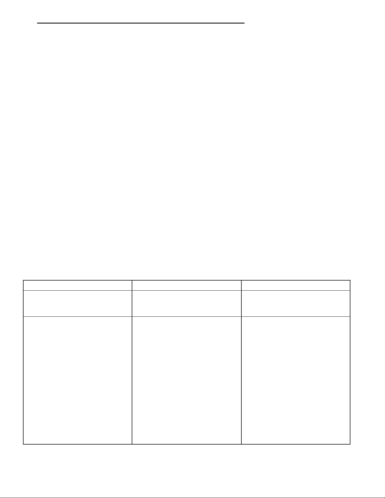
bolts (Fig. 1) and remove crossmember.
(8) Support axle with hydraulic jack.
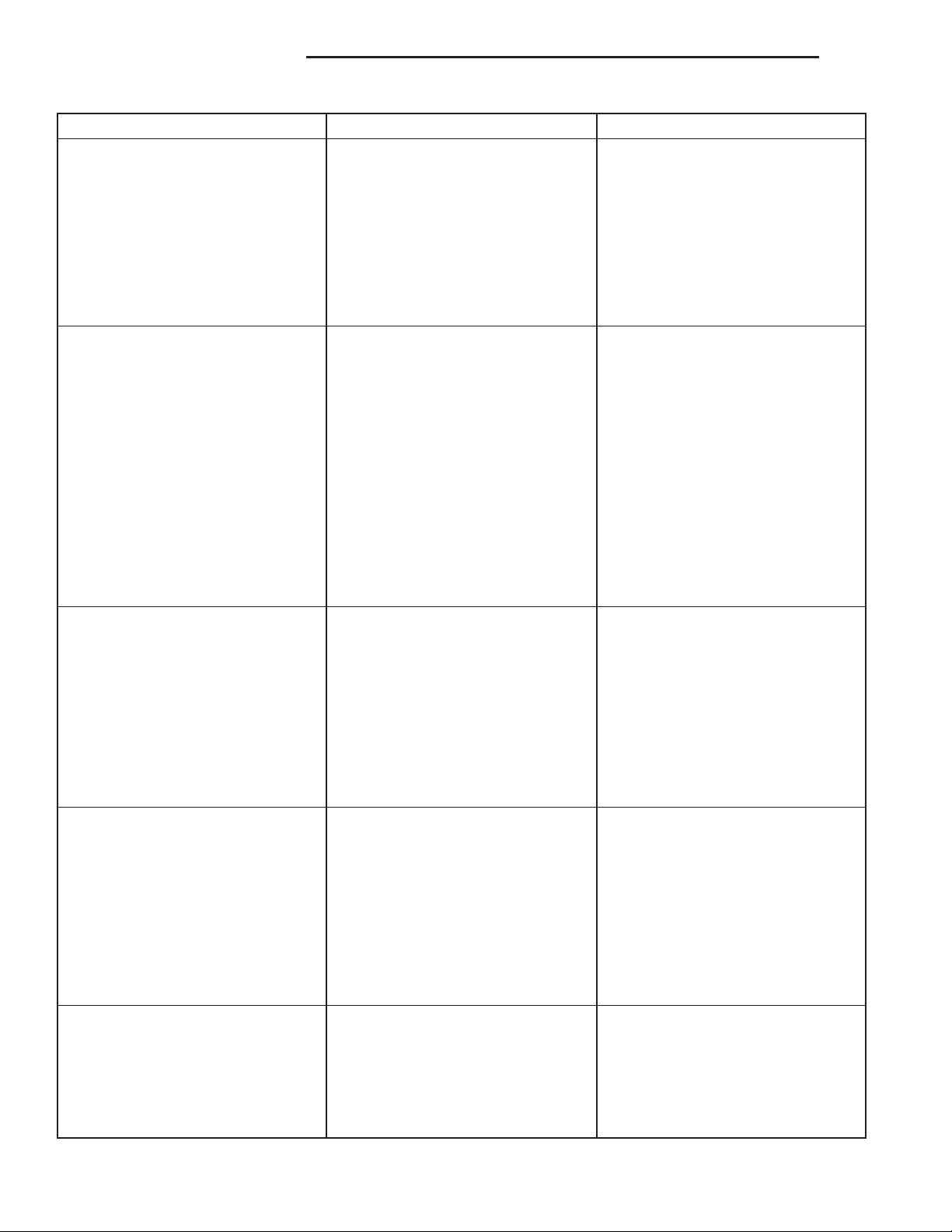
(9) Remove axle housing pinion mounting bolts
(Fig. 2).
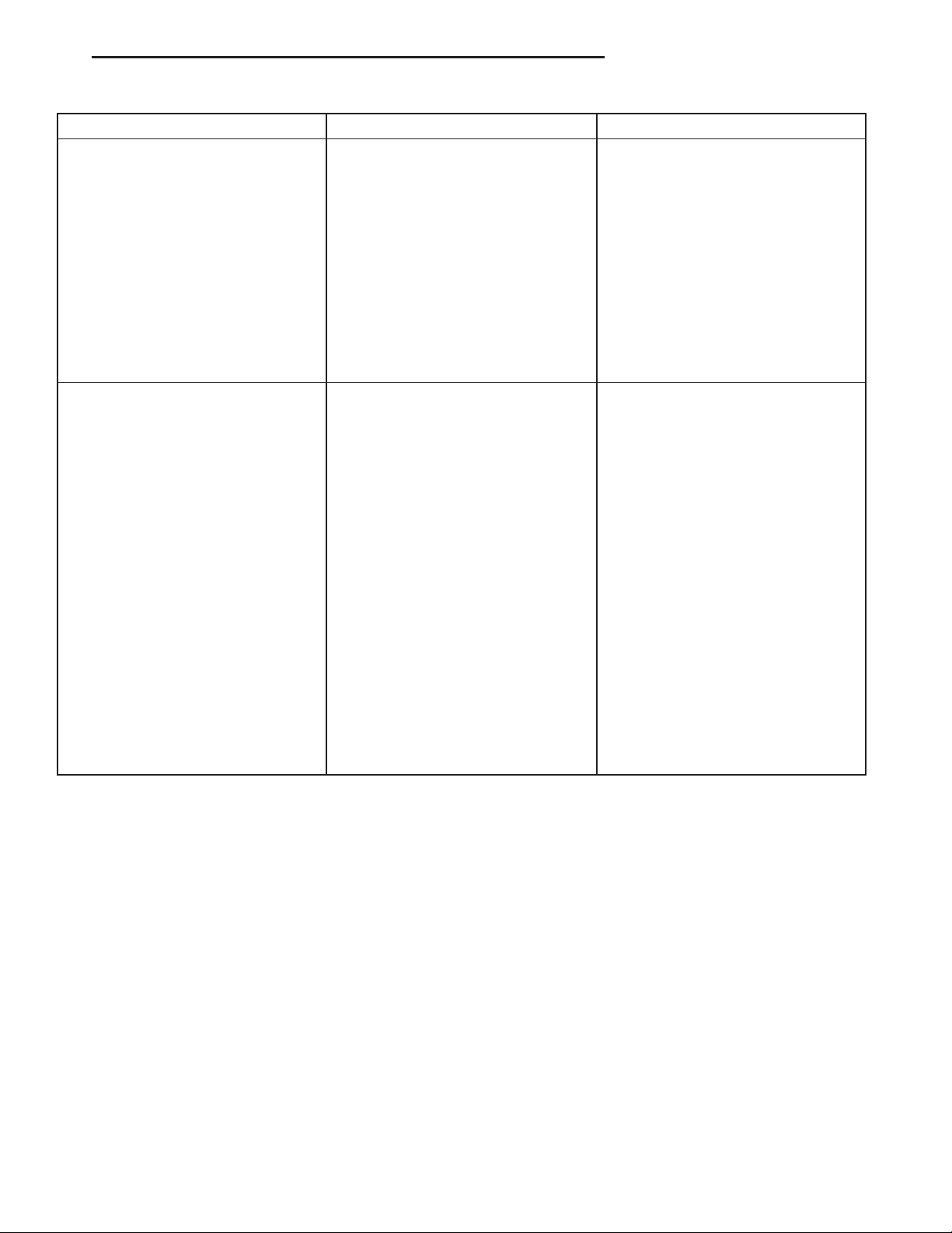
(10) Remove axle shaft tube mounting bolts (Fig.
3).
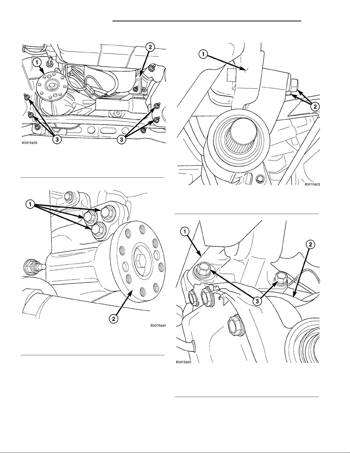
(11) Remove differential housing mounting bolts
(Fig. 4).
(12) Lower axle from the vehicle.
INSTALLATION
(1) Raise axle into position.
(2) Install axle mounting bolts and tighten nuts to
95 N·m (70 ft. lbs.).
(3) Install suspension crossmember and bolts.
Tighten crossmember nuts to 102 N·m (75 ft. lbs.).
(4) Install front propeller shaft with reference
marks aligned (Fig. 5) and tighten bolts to 115 N·m
(85 ft. lbs.).
(5) Install exhaust crossover.
(6) Install axle half shafts.
(7) Check the differential fluid level and add fluid
if necessary.
(8) Install tire and wheel assemblies.
(9) Remove support lower the vehicle.
ADJUSTMENTS
Ring gear and pinion are supplied as matched sets
only. The identifying numbers for the ring gear and
Page 22
3 - 22 FRONT AXLE - C205F DR
FRONT AXLE - C205F (Continued)
Fig. 1 SUSPENSION CROSSMEMBER
1 - PINION FLANGE
2 - AXLE TUBE MOUNTING BRACKET
3 - CROSSMEMBER BOLTS
Fig. 2 HOUSING PINION MOUNTING BOLTS
1 - MOUNTING BOLTS
2 - PINION FLANGE
Fig. 3 AXLE TUBE MOUNT
1 - MOUNTING BOLTS
2 - BOLTS
pinion are painted onto the pinion gear shaft and the
side of the ring gear. A plus (+) number, minus (–)
number or zero (0) along with the gear set sequence
number (01 to 99) is on each gear. This first number
is the amount (in thousandths of an inch) the depth
varies from the standard depth setting of a pinion
marked with a (0). The next two numbers are the
sequence number of the gear set. The standard setting from the center line of the ring gear to the back
Fig. 4 DIFFERENTIAL MOUNT
1 - DIFFERENTIAL MOUNT
2 - DIFFERENTIAL HOUSING
3 - MOUNTING BOLTS
face of the pinion is 99.690 mm (3.925 in.). The standard depth provides the best teeth contact pattern.
Compensation for pinion depth variance is
achieved with select shims. The shims are placed
Page 23

DR FRONT AXLE - C205F 3 - 23
FRONT AXLE - C205F (Continued)
Fig. 6 ADJUSTMENT SHIM
1 - PINION GEAR DEPTH SHIM
2 - DIFFERENTIAL BEARING PRELOAD SHIM
3 - RING GEAR
4 - DIFFERENTIAL BEARING PRELOAD SHIM
5 - COLLAPSIBLE SPACER
Fig. 5 COMPANION FLANGE
1 - COMPANION FLANGE
2 - PROPELLER SHAFT
3 - FLANGE YOKE
4 - REFERENCE MARK
between the rear pinion bearing cone and the pinion
gear head. (Fig. 6).
If a new gear set is being installed, note the depth
variance marked on both the original and replacement pinion. Add or subtract the thickness of the
original depth shims to compensate for the difference
in the depth variances. Refer to the Pinion Gear
PINION GEAR DEPTH VARIANCE
Original Pinion
New Pinion Gear Depth Variance
Gear Depth
Variance
24 23 22 21 0 +1 +2 +3 +4
+4 +0.008 +0.007 +0.006 +0.005 +0.004 +0.003 +0.002 +0.001 0
+3 +0.007 +0.006 +0.005 +0.004 +0.003 +0.002 +0.001 0 20.001
+2 +0.006 +0.005 +0.004 +0.003 +0.002 +0.001 0 20.001 20.002
+1 +0.005 +0.004 +0.003 +0.002 +0.001 0 20.001 20.002 20.003
0 +0.004 +0.003 +0.002 +0.001 0 20.001 20.002 20.003 20.004
21 +0.003 +0.002 +0.001 0 20.001 20.002 20.003 20.004 20.005
22 +0.002 +0.001 0 20.001 20.002 20.003 20.004 20.005 20.006
23 +0.001 0 20.001 20.002 20.003 20.004 20.005 20.006 20.007
24 0 20.001 20.002 20.003 20.004 20.005 20.006 20.007 20.008
Depth Variance charts. Note where Old and New
Pinion Marking columns intersect. Intersecting figure
represents plus or minus amount needed.
Note the painted number on the shaft of the drive
pinion (–1, –2, 0, +1, +2, etc.). The numbers represent thousands of an inch deviation from the standard. If the number is negative, add that value to the
required thickness of the depth shim(s). If the number is positive, subtract that value from the thickness
of the depth shim(s). If the number is 0 no change is
necessary.
Page 24
3 - 24 FRONT AXLE - C205F DR
FRONT AXLE - C205F (Continued)
PINION DEPTH MEASUREMENT AND ADJUSTMENT
Measurements are taken with pinion cups and pinion bearings installed in housing. Take measurements with a Pinion Gauge Set, Pinion Block 8177,
Arbor Discs 8541 and Dial Indicator C-3339 (Fig. 7).
Fig. 8 PINION HEIGHT BLOCK
1 - PINION BLOCK
2 - PINION HEIGHT BLOCK
Fig. 7 PINION GEAR DEPTH GAUGE
1 - DIAL INDICATOR
2 - ARBOR
3 - PINION HEIGHT BLOCK
4 - CONE
5 - SCREW
6 - PINION BLOCK
7 - SCOOTER BLOCK
8 - ARBOR DISC
(1) Assemble Pinion Height Block 6739, Pinion
Block 8177 and rear pinion bearing onto Screw 6741
(Fig. 7).
(2) Insert assembled height gauge components,
rear bearing and screw into the housing through the
pinion bearing cups (Fig. 8).
(3) Install front pinion bearing and Cone 6740 onto
the screw hand tight (Fig. 7).
(4) Place Arbor Discs 8541 on Arbor D-115-3 in
position in the housing side bearing cradles (Fig. 9).
Install differential bearing caps on arbor discs and
tighten cap bolts to specification.
(5) Assemble Dial Indicator C-3339 into Scooter
Block D-115-2 and secure set screw.
(6) Place Scooter Block/Dial Indicator in position
in the housing so dial probe and scooter block are
flush against the surface of the pinion height block.
Hold scooter block in place and zero the dial indicator. Tighten dial indicator face lock screw.
(7) Slide the dial indicator probe across the gap
between the pinion height block and the arbor bar
Fig. 9 PINION GAUGE TOOLS
1 - ARBOR DISC
2 - PINION BLOCK
3 - ARBOR
4 - PINION HEIGHT BLOCK
with the scooter block against the pinion height block
(Fig. 10). Slide the dial probe to the crest of the arbor
bar and record the highest reading.
(8) Select a shim equal to the dial indicator reading plus the drive pinion gear depth variance number
marked on the shaft of the pinion gear using the
opposite sign on the variance number. For example, if
the depth variance is –2, add +0.002 in. to the dial
indicator reading.
Page 25
DR FRONT AXLE - C205F 3 - 25
FRONT AXLE - C205F (Continued)
Fig. 10 PINION GEAR DEPTH MEASUREMENT
1 - ARBOR
2 - SCOOTER BLOCK
3 - DIAL INDICATOR
(9) Remove the pinion depth gauge components
from the housing
DIFFERENTIAL BEARING PRELOAD AND GEAR
BACKLASH
Differential side bearing preload and gear backlash
is achieved by selective shims inserted between the
bearing cup and the housing. The proper shim thickness can be determined using slip-fit Dummy Bearings 8398 in place of the differential side bearings
and a Dial Indicator C-3339. Before proceeding with
the differential bearing preload and gear backlash
measurements, measure the pinion gear depth and
prepare the pinion for installation. Establishing
proper pinion gear depth is essential to establishing
gear backlash and tooth contact patterns. After the
overall shim thickness to take up differential side
play is measured, the pinion is installed, and the
gear backlash shim thickness is measured. The overall shim thickness is the total of the dial indicator
reading, starting point shim thicknesses, and the
preload specification added together. The gear backlash measurement determines the thickness of the
shim used on the ring gear side of the differential
case. Subtract the gear backlash shim thickness from
the total overall shim thickness and select that
amount for the pinion side of the differential (Fig.
11).
Fig. 11 ADJUSTMENT SHIM
1 - PINION GEAR DEPTH SHIM
2 - DIFFERENTIAL BEARING PRELOAD SHIM
3 - RING GEAR
4 - DIFFERENTIAL BEARING PRELOAD SHIM
5 - COLLAPSIBLE SPACER
(2) Install ring gear if necessary, on differential
case and tighten bolts to specification.
(3) Install Dummy Bearings 8398 on differential
case.
(4) Install differential case in the housing.
(5) Insert Dummy Shims 8107 3.0 mm (0.118 in.)
starting point shims between both dummy bearings
and the housing (Fig. 12).
SHIM SELECTION
NOTE: It is difficult to salvage the differential side
bearings during the removal procedure. Install
replacement bearings if necessary.
(1) Remove side bearings from differential case.
Fig. 12 DUMMY SHIM
1 - DUMMY SHIM
2 - DIFFERENTIAL HOUSING
3 - DIFFERENTIAL CASE
4 - DUMMY BEARINGS
Page 26
3 - 26 FRONT AXLE - C205F DR
FRONT AXLE - C205F (Continued)
(6) Install the marked bearing caps in their correct
positions. Install and snug the bolts.
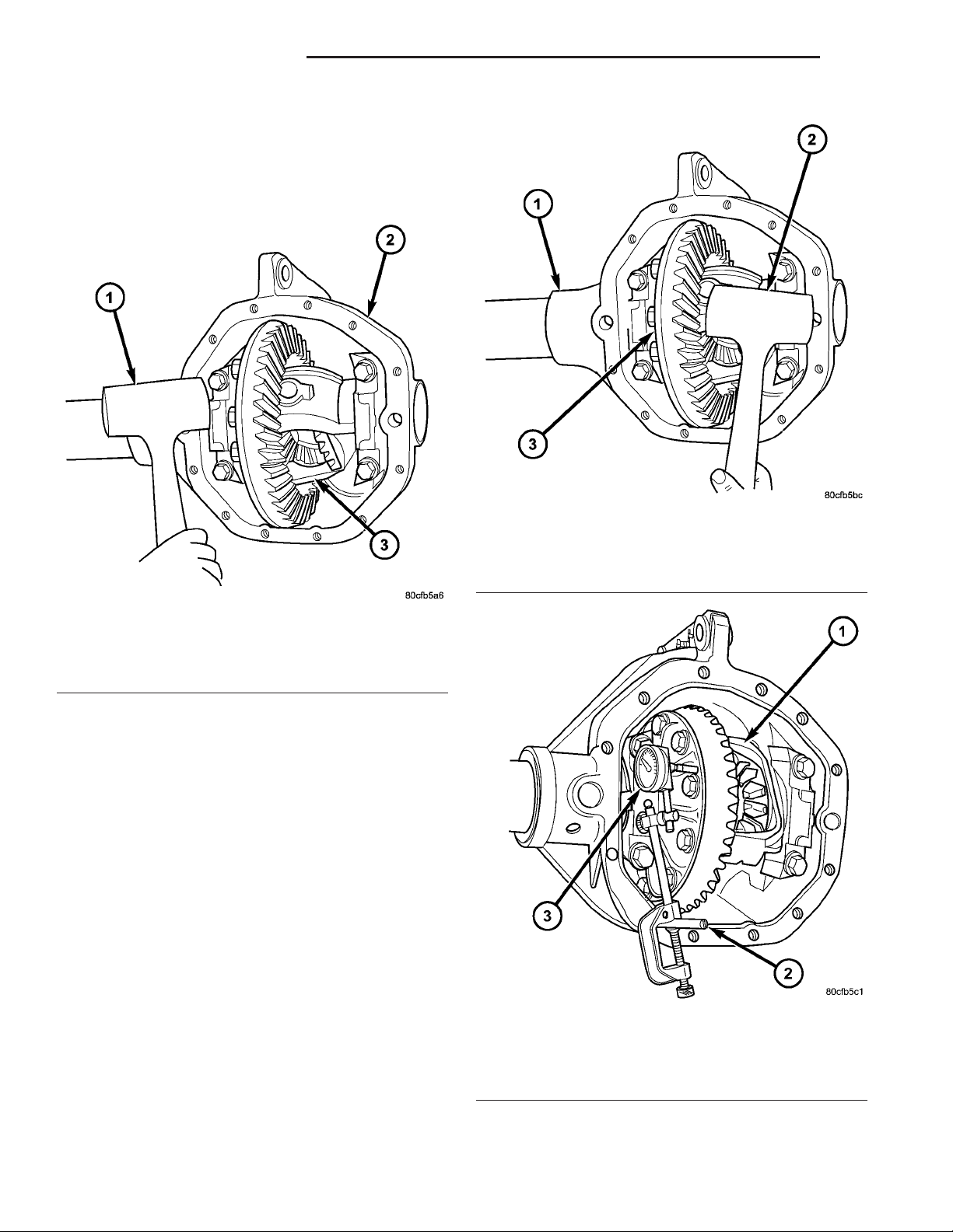
(7) Using a dead-blow hammer to seat the differential dummy bearings to each side of the differential
housing (Fig. 13) and (Fig. 14).
Fig. 13 SEAT PINION GEAR SIDE
1 - DEAD-BLOW HAMMER
2 - HOUSING
3 - PINION GEAR SIDE
(8) Install Pilot Stud C-3288-B in cover bolt hole
below ring gear.
(9) Attach Dial Indicator C-3339 to post and position dial indicator plunger on a flat surface on a ring
gear bolt head (Fig. 15).
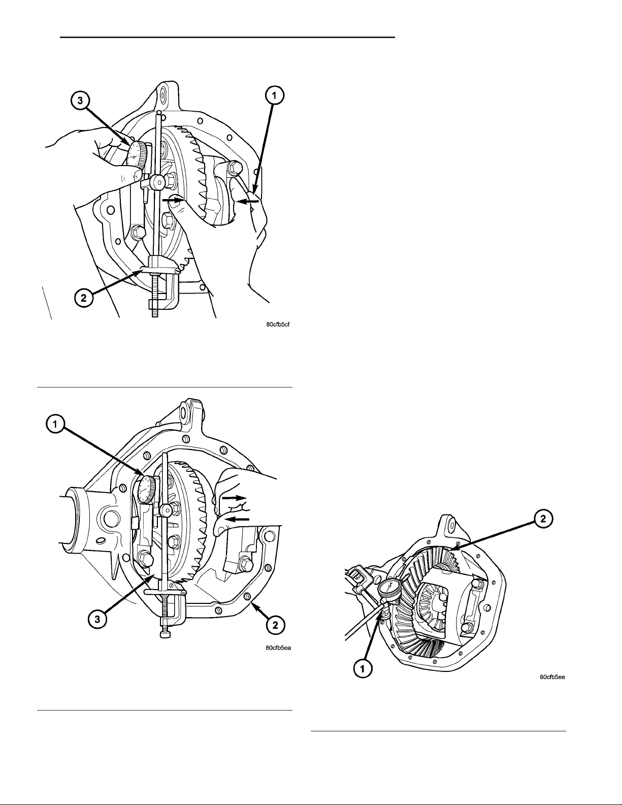
(10) Push and hold differential to the pinion gear
side of the housing (Fig. 16) and zero dial indicator.
(11) Push and hold differential case to the ring
gear side and record dial indicator reading (Fig. 17).
(12) Add the dial indicator reading to the starting
point shim thicknesses to determine the total shim
thickness necessary to achieve zero differential end
play.
(13) Add 0.2 mm (0.008 in) to the zero end play
total. This new total represents the shims needed to
preload the new differential case bearings.
(14) Rotate dial indicator out of the way on pilot
stud.
(15) Remove differential case, dummy bearings
and dummy shims from the housing.
(16) Install the pinion gear in the housing. Install
the companion flange and establish the correct pinion
rotating torque.
Fig. 14 SEAT RING GEAR SIDE
1 - HOUSING
2 - DEAD-BLOW HAMMER
3 - RING GEAR SIDE
Fig. 15 DIFFERENTIAL SIDE PLAY
1 - DIFFERENTIAL
2 - PILOT STUD
3 - DIAL INDICATOR
4 - HOUSING
(17) Install differential case and Dummy Bearings
in the housing with a single dummy shim on the ring
gear side of the axle and tighten retaining cap bolts.
Page 27
DR FRONT AXLE - C205F 3 - 27
FRONT AXLE - C205F (Continued)
(20) Zero dial indicator face to pointer.
(21) Push and hold differential case to ring gear
side of the housing.
(22) Record dial indicator reading.
(23) Subtract 0.05 mm (0.002 in.) from the dial
indicator reading to compensate for backlash between
ring and pinion gears. Add the resulting measurement to the thickness of the single dummy shim.
This is the thickness of shim required to achieve
proper backlash.
(24) Subtract the backlash shim thickness from
the total preload shim thickness. The remainder is
the shim thickness required on the pinion side of the
housing.
(25) Rotate dial indicator out of the way on pilot
stud.
(26) Remove differential case, dummy bearings
and dummy shim from the housing.
(27) Install new side bearing cones and cups on
differential case.
(28) Install Spreader W-129-B and Adapter Plates
8142-A on the housing and spread open enough to
Fig. 16 ZERO DIAL INDICATOR
1 - PINION GEAR SIDE
2 - PILOT STUD
3 - DIAL INDICATOR
receive differential case.
CAUTION: Never spread over 0.50 mm (0.020 in). If
the housing is over-spread, it could be distorted or
damaged.
Fig. 17 RECORD DIAL INDICATOR
1 - DIAL INDICATOR
2 - HOUSING
3 - RING GEAR SIDE
(18) Position the dial indicator plunger on a flat
surface between the ring gear bolt heads (Fig. 15).
(19) Push and hold differential case toward pinion.
(29) Place the side bearing shims in the differential housing against the housing shoulder.
(30) Install the differential case in the housing.
(31) Rotate the differential case several times to
seat the side bearings.
(32) Position the dial indicator plunger against a
ring gear tooth (Fig. 18).
Fig. 18 RING GEAR BACKLASH
1 - RING GEAR
2 - DIAL INDICATOR
(33) Push and hold ring gear upward while not
allowing the pinion gear to rotate.
Page 28
3 - 28 FRONT AXLE - C205F DR
FRONT AXLE - C205F (Continued)
(34) Zero dial indicator face to pointer.
(35) Push and hold ring gear downward while not
allowing the pinion gear to rotate. Dial indicator
reading should be between 0.12 mm (0.005 in.) and
0.20 mm (0.008 in.). If backlash is not within specifications transfer the necessary amount of shim thickness from one side of the differential housing to the
other (Fig. 19).
(36) Verify differential case and ring gear runout
by measuring ring to pinion gear backlash at eight
locations around the ring gear. Readings should not
vary more than 0.05 mm (0.002 in.). If readings vary
more than specified, the ring gear or the differential
case is defective.
After the proper backlash is achieved, perform the
Gear Contact Pattern procedure.
• Gear contact pattern correct (Fig. 20). Backlash
and pinion depth is correct.
Fig. 20 CORRECT CONTACT PATTERN
• Ring gear too far away from pinion gear (Fig.
21). Decrease backlash by moving the ring closer to
the pinion gear.
Fig. 19 BACKLASH SHIM ADJUSTMENT
GEAR CONTACT PATTERN
Gear tooth contact pattern is used to verify the correct running position of the ring and pinion gears.
This will produce low noise and long gear life. Gears
which are not positioned properly may be noisy and
have shorten gear life.
(1) Wipe clean each tooth of the ring gear.
(2) Apply gear marking compound to all of the ring
gear teeth.
(3) Verify bearing cap bolts are torque specification.
(4) Apply the brakes lightly to create at 14 N·m
(10 ft. lbs.) pinion rotating torque.
(5) Rotate the pinion/pinion yoke 4 full revolutions
in each directions.
(6) Read gear tooth contact pattern:
Fig. 21 INCORRECT BACKLASH
1 - COAST SIDE TOE
2 - DRIVE SIDE HEEL
• Ring gear too close to pinion gear (Fig. 22).
Increase backlash, by moving the ring away from the
pinion gear.
Fig. 22 INCORRECT BACKLASH
1 - DRIVE SIDE TOE
2 - COAST SIDE HEEL
Page 29
DR FRONT AXLE - C205F 3 - 29
FRONT AXLE - C205F (Continued)
• Ring gear too far away from pinion gear (Fig.
23). Decrease backlash, by moving the ring closer to
the pinion gear.
Fig. 23 INCORRECT BACKLASH
1 - DRIVE SIDE HEEL
2 - COAST SIDE HEEL
• Ring gear too close to pinion gear (Fig. 24).
Increase backlash, by moving the ring away from the
pinion gear.
• Pinion gear set too low (Fig. 25). Increase pinion
gear height, by increasing the pinion depth shim
thickness.
Fig. 25 LOW PINION HEIGHT
• Pinion gear set too high (Fig. 26). Decrease pinion depth, by decreasing the pinion depth shim thickness.
Fig. 24 INCORRECT BACKLASH
1 - DRIVE SIDE TOE
2 - COAST SIDE TOE
SPECIFICATIONS
Differential Case Flange Runout 0.076 mm (0.003 in.)
Differential Side Gear Clearance 0-0.15 mm (0-0.006 in.)
Pinion Bearing Preload - New Bearings 2.0-2.8 N·m (18-25 in. lbs.)
Pinion Bearing Preload - Original Bearings 1-2 N·m (10-20 in. lbs.)
Fig. 26 HIGH PINION HEIGHT
AXLE SPECIFICATIONS
DESCRIPTION SPECIFICATION
Axle Ratio 3.55, 3.92
Ring Gear Diameter 205 mm (8.0 in.)
Ring Gear Backlash 0.12-0.20 mm (0.005-0.008 in.)
Ring Gear Runout 0.12 mm (0.005 in.)
Page 30
3 - 30 FRONT AXLE - C205F DR
FRONT AXLE - C205F (Continued)
TORQUE SPECIFICATIONS
DESCRIPTION N·m Ft. Lbs. In. Lbs.
Mounting Nuts 95 70 -
Differential Fill Hole Plug 34 25 -
Differential Cover Bolts 22 15 -
Bearing Cap Bolts 61 45 -
Ring Gear Bolts 108 80 -
Pinion Nut 271-475 200-350 -
SPECIAL TOOLS
PULLER C-452
PULLER C-293-PA
ADAPTER C-293-42
ADAPTER C-293-48
PLUG C-293-3
HOLDER 6719A
HANDLE C-4171
Page 31

DR FRONT AXLE - C205F 3 - 31
FRONT AXLE - C205F (Continued)
REMOVER 8401
INSTALLER 8693
REMOVER 8831
INSTALLER 8695
INSTALLER 8692
INSTALLER 6448
REMOVER C-4660-A
INSTALLER 8694
CUP 8150
Page 32

3 - 32 FRONT AXLE - C205F DR
FRONT AXLE - C205F (Continued)
INSTALLER 5063
PINION BLOCK 8177
PINION DEPTH SET 6775
DIAL INDICATOR C-3339
DUMMY SHIM 8107
DUMMY BEARING 8398
SPREADER W-129-B
PILOTS C-3288-B
INSTALLER C-3718
ADAPTER PLATES 8142A
Page 33

DR FRONT AXLE - C205F 3 - 33
AXLE SHAFTS
REMOVAL
(1) Remove half shaft from vehicle.
(2) Remove skid plate, if equipped.
(3) Clean axle seal area.
(4) Remove snap ring from the axle shaft.
(5) Remove axle with Remove 8420A Collar 8420-3
and Slide Hammer C-3752 (Fig. 27).
Fig. 27 AXLE SHAFT PULLER
1 - SNAP RING GROVE
2 - SLID HAMMER THREADS
3 - REMOVER BLOCKS
4 - REMOVER COLLAR
INSTALLATION
INSTALLATION
(1) Clean axle shaft bore clean.
(2) Install a new axle shaft seal with Installer
8694 and Handle C-4171.
(3) Lubricate seal lip with gear lubricant.
(4) Insert axle shaft through seal, bearing, and
engage it into side gear splines. Push firmly on the
axle shaft to engage the snap-ring.
NOTE: Use care to prevent shaft splines from damaging axle shaft seal lip.
(5) Install axle shaft O-ring.
(6) Check the differential fluid level and add fluid
if necessary.
(7) Install skid plate, if necessary.
(8) Install half shaft.
AXLE BEARINGS
REMOVAL
(1) Remove half shaft from vehicle.
(2) Remove skid plate, if equipped.
(3) Clean axle seal area.
(4) Remove axle shaft O-ring.
(5) Remove axle shaft.
(6) Remove axle shaft seal.
(7) Install axle shaft bearing Remover C-4660-A in
the bearing (Fig. 28). Then tighten the nut to spread
the remover in the bearing.
NOTE: Use care to prevent shaft splines from damaging axle shaft seal lip.
(1) Lubricate bearing bore and seal lip with gear
lubricant.
(2) Insert axle shaft through seal, bearing, and
engage it into side gear splines. Push firmly on the
axle shaft to engage the snap-ring.
(3) Check the differential fluid level and add fluid
if necessary.
(4) Install skid plate, if necessary.
(5) Install half shaft.
AXLE SHAFT SEALS
REMOVAL
(1) Remove half shaft from vehicle.
(2) Remove skid plate, if equipped.
(3) Clean axle seal area.
(4) Remove axle shaft O-ring.
(5) Remove axle shaft.
(6) Remove axle shaft seal with a small pry bar.
Fig. 28 BEARING REMOVER
1 - AXLE BEARING
2 - NUT
3 - REMOVER
(8) Install the bearing remove cup, bearing and
nut (Fig. 29). Then tighten the nut to draw the bearing out.
Page 34

3 - 34 FRONT AXLE - C205F DR
AXLE BEARINGS (Continued)
(6) Install axle shaft O-ring.
(7) Check the differential fluid level and add fluid
if necessary.
(8) Install skid plate, if necessary.
(9) Install half shaft.
PINION SEAL
REMOVAL
(1) Remove skid plate, if equipped.
(2) Remove both half shafts.
(3) Mark the propeller shaft and pinion companion
flange (Fig. 31) for installation reference.
Fig. 29 BEARING REMOVER CUP
1 - REMOVER CUP
2 - BEARING
3 - NUT
(9) Inspect the axle shaft tube bore for roughness
and burrs. Remove as necessary.
INSTALLATION
(1) Wipe the axle shaft tube bore clean.
(2) Install axle shaft bearing with Installer 5063
and Handle C-4171 (Fig. 30).
Fig. 30 BEARING INSTALLER
1 - INSTALLER
2 - HANDLE
(3) Install a new axle shaft seal with Installer
8694 and Handle C-4171.
(4) Lubricate seal lip with gear lubricant.
(5) Insert axle shaft through seal, bearing and
engage it into side gear splines. Push firmly on the
axle shaft to engage the snap-ring.
NOTE: Use care to prevent shaft splines from damaging axle shaft seal lip.
Fig. 31 COMPANION FLANGE
1 - COMPANION FLANGE
2 - PROPELLER SHAFT
3 - FLANGE YOKE
4 - REFERENCE MARK
(4) Remove the front propeller shaft.
(5) Rotate the pinion gear three or four times and
verify pinion rotates smoothly.
(6) Record pinion rotating torque with an inch
pound torque wrench, for installation reference (Fig.
32).
(7) Position Holder 6719 against the companion
flange and install a four bolts and washers into the
threaded holes and tighten the bolts.
(8) Remove the pinion nut.
(9) Remove the companion flange with Remover
C-452 (Fig. 33).
(10) Remove pinion seal with a pry tool or a slide
hammer mounted screw.
Page 35

DR FRONT AXLE - C205F 3 - 35
PINION SEAL (Continued)
Fig. 34 PINION SEAL INSTALLER
1 - HANDLE
2 - INSTALLER
(4) Position holder against the companion flange
and install four bolts and washers into the threaded
holes. Tighten the bolt and washer so that the holder
is held to the flange.
Fig. 32 PINION ROTATING TORQUE
1 - COMPANION FLANGE
2 - INCH POUND TORQUE WRENCH
(5) Install a new pinion nut onto the pinion shaft
and tighten the pinion nut until there is zero bearing
end-play (Fig. 35).
Fig. 33 COMPANION FLANGE REMOVER
1 - COMPANION FLANGE
2 - PULLER TOOL
CAUTION: Do not exceed 271 N·m (200 ft. lbs.) the
minimum tightening torque when installing the
companion flange at this point. Damage to the collapsible spacer or bearings may result.
INSTALLATION
(1) Apply a light coating of gear lubricant on the
lip of pinion seal.
(2) Install seal with Installer 8695 and Handle
C-4171 (Fig. 34).
(3) Install companion flange onto the pinion with
Installer C-3718 and Holder 6719A.
Fig. 35 COMPANION FLANGE HOLDER
1 - DIFFERENTIAL HOUSING
2 - COMPANION FLANGE HOLDER
3 - TORQUE WRENCH
Page 36

3 - 36 FRONT AXLE - C205F DR
PINION SEAL (Continued)
CAUTION: Never loosen pinion nut to decrease pinion bearing rotating torque and never exceed specified preload torque. If preload torque or rotating
torque is exceeded a new collapsible spacer must
be installed.
(6) Record pinion rotating torque using an inch
pound torque wrench. The rotating torque should be
equal to the reading recorded during removal plus an
additional 0.56 N·m (5 in. lbs.) (Fig. 36).
DIFFERENTIAL
DESCRIPTION
The differential case is a one-piece design. The differential pinion shaft is retained with a snap ring.
Differential bearing preload and ring gear backlash
is adjusted by the use of adjusters. The adjuster are
between the differential bearings and the differential
housing. Pinion bearing preload is set and maintained by the use of a collapsible spacer. The
stamped steel cover provides a means for inspection
and servicing the differential.
OPERATION
During straight-ahead driving, the differential pinion gears do not rotate on the pinion mate shaft. This
occurs because input torque applied to the gears is
divided and distributed equally between the two side
gears. As a result, the pinion gears revolve with the
pinion mate shaft but do not rotate around it (Fig.
37).
Fig. 36 PINION ROTATION TORQUE
1 - COMPANION FLANGE
2 - INCH POUND TORQUE WRENCH
(7) If rotating torque is low, tighten the pinion nut
in 6.8 N·m (5 ft. lbs.) increments until the proper
rotating torque is achieved.
CAUTION: If maximum tightening torque 475 N·m
(350 ft. lbs.) is reached prior to reaching the
required rotating torque, the collapsible spacer may
have been damaged. Replace the collapsible
spacer.
(8) Install propeller shaft with reference marks
aligned.
(9) Add gear lubricant to differential housing if
necessary.
(10) Install half shafts and skid plate if equipped.
Fig. 37 DIFFERENTIAL-STRAIGHT AHEAD DRIVING
1 - IN STRAIGHT AHEAD DRIVING EACH WHEEL ROTATES AT
100% OF CASE SPEED
2 - PINION GEAR
3 - SIDE GEAR
4 - PINION GEARS ROTATE WITH CASE
When turning corners, the outside wheel must
travel a greater distance than the inside wheel to
complete a turn. To accomplish this, the differential
allows the axle shafts to turn at unequal speeds (Fig.
38). In this instance, the input torque applied to the
pinion gears is not divided equally. The pinion gears
now rotate around the pinion mate shaft in opposite
directions. This allows the side gear and axle shaft
attached to the outside wheel to rotate at a faster
speed.
REMOVAL
(1) Remove differential housing cover and drain
fluid.
Page 37

DR FRONT AXLE - C205F 3 - 37
DIFFERENTIAL (Continued)
(6) Install a Pilot Stud L-4438 at the left side of
the differential housing. Attach Dial Indicator C-3339
to pilot stud. Load the indicator plunger against the
opposite side of the housing and zero the indicator.
(7) Spread the housing to remove the differential
case from the housing (Fig. 40). Measure the distance
with the dial indicator.
CAUTION: Never spread over 0.50 mm (0.020 in). If
the housing is over-spread, it could be distorted or
damaged.
Fig. 38 DIFFERENTIAL-ON TURNS
1 - PINION GEARS ROTATE ON PINION SHAFT
(2) Remove axle shafts.
(3) Loosen bearing cap bolts.
NOTE: Differential bearing cap reference numbers
are stamped on caps and machined flat on the
housing. If reference numbers cannot be found,
make new marks for later reference.
(4) Install Adapter Plates 8142-A onto the housing.
(5) Install Spreader W-129-B onto the adapter
plates (Fig. 39) and tighten the turnbuckle fingertight.
Fig. 40 DIAL INDICATOR LOCATION
1 - DIAL INDICATOR
2 - SPREADER
(8) Remove dial indicator.
(9) While holding the differential case in position,
remove bearing cap bolts and caps.
(10) Remove differential from the housing (Fig.
41). Ensure differential bearing cups and shims
remain in position on the differential bearings.
(11) Tag differential bearing cups and shims to
indicate their location.
(12) Remove spreader from housing.
Fig. 39 ADAPTER PLATES AND SPREADER
1 - ADAPTER PLATE
2 - SPREADER
DISASSEMBLY
(1) Remove ring gear.
(2) Remove roll-pin holding mate shaft in housing.
(3) Remove pinion gear mate shaft.
(4) Rotate differential side gears and remove the
pinion mate gears and thrust washers (Fig. 42).
(5) Remove the differential side gears and thrust
washers.
Page 38

3 - 38 FRONT AXLE - C205F DR
DIFFERENTIAL (Continued)
ASSEMBLY
(1) Install differential side gears and thrust wash-
ers.
(2) Install pinion mate gears and thrust washers.
(3) Install pinion gear mate shaft.
(4) Align the hole in the pinion gear mate shaft
with the hole in the differential case.
(5) Install the roll-pin in the differential case a
punch and hammer (Fig. 43). Peen the edge of the
roll-pin hole in the differential case in two places
180° apart.
(6) Lubricate all differential components with
hypoid gear lubricant.
(7) Install ring gear.
1 - HOUSING
2 - DIFFERENTIAL
3 - BEARING CUPS
Fig. 41 DIFFERENTIAL
Fig. 43 PINION MATE SHAFT ROLL-PIN
1 - PUNCH
2 - PINION MATE SHAFT
3 - MATE SHAFT LOCKPIN
INSTALLATION
NOTE: If replacement differential bearings or differential case are replaced, Refer to adjustments for
Differential Bearing Preload and Gear Backlash procedures.
Fig. 42 PINION MATE GEAR
1 - THRUST WASHER
2 - SIDE GEAR
3 - PINION MATE GEAR
(1) Install Spreader W-129-B with the Adapter
Plates 8142-A and install the safety holddown
clamps. Tighten the tool turnbuckle finger-tight.
(2) Install a Pilot Stud L-4438 at the left side of
the differential housing. Attach Dial Indicator C-3339
to pilot stud. Load indicator plunger against the
opposite side of the housing and zero the indicator.
Page 39

DR FRONT AXLE - C205F 3 - 39
DIFFERENTIAL (Continued)
(3) Spread housing and measure the distance with
the dial indicator.
CAUTION: Never spread over 0.50 mm (0.020 in). If
the housing is over-spread, it could be distorted or
damaged.
(4) Remove dial indicator.
(5) Install differential case in the housing. Ensure
differential bearing cups remain in position on the
bearings and the differential preload shims are
seated in the housing. Tap differential case to ensure
bearings cups are seated in the housing.
(6) Install bearing caps to their original locations
and loosely install cap bolts.
(7) Remove housing spreader.
(8) Tighten the bearing cap bolts to 61 N·m (45 ft.
lbs.).
(9) Install axle shafts.
(10) Apply a bead of red Mopar Silicone Sealant or
equivalent to the housing cover.
CAUTION: If cover is not installed within 3 to 5 minutes, the cover must be cleaned and new RTV
applied or adhesion quality will be compromised.
(11) Install cover and tighten bolts in a criss-cross
pattern to 22 N·m (15 ft. lbs.).
(12) Fill differential with lubricant.
DIFFERENTIAL CASE
BEARINGS
REMOVAL
(1) Remove differential from housing.
(2) Remove bearings from the differential case
with Puller/Press C-293-PA, Adapters C-293-48 and
Plug C-293-3 (Fig. 44).
INSTALLATION
(1) Install differential case bearings with Installer
C-3716-A and Handle C-4171 (Fig. 45).
(2) Install differential into the housing.
Fig. 44 DIFFERENTIAL CASE BEARING PULLER
1 - PULLER
2 - ADAPTERS
3 - BEARING
4 - DIFFERENTIAL
5 - PLUG
Fig. 45 DIFFERENTIAL CASE BEARINGS
1 - HANDLE
2 - DIFFERENTIAL
3 - BEARING
4 - INSTALLER
Page 40

3 - 40 FRONT AXLE - C205F DR
PINION GEAR/RING GEAR
REMOVAL
NOTE: The ring gear and pinion are serviced in a
matched set. Never replace one without replacing
the other.
(1) Remove differential from housing.
(2) Place differential case in a vise with soft jaw
(Fig. 46).
(3) Remove bolts holding ring gear to differential
case.
(4) Drive ring gear from differential case with a
soft hammer (Fig. 46).
Fig. 46 RING GEAR
1 - DIFFERENTIAL CASE
2 - RING GEAR
3 - RAWHIDE HAMMER
(5) Mark the companion yoke and companion
flange for installation reference.
(6) Remove companion flange bolts and tie the propeller shaft to the vehicle underbody.
(7) Rotate companion flange three or four times
and verify flange rotates smoothly.
(8) Record pinion rotating torque an inch pound
torque wrench for installation reference (Fig. 47).
(9) Install bolts into two of the threaded holes in
the companion flange 180° apart.
(10) Position Holder 6719 against the companion
flange and install a bolt and washer into one of the
remaining threaded holes. Tighten the bolts so that
the Holder 6719 is held to the flange.
(11) Remove the pinion nut.
(12) Remove the companion flange with Remover
C-452 (Fig. 48).
(13) Remove pinion from differential housing.
(14) Remove pinion seal with a pry tool or a slide
hammer mounted screw.
Fig. 47 PINION ROTATING TORQUE
1 - PINION COMPANION FLANGE
2 - TORQUE WRENCH
Fig. 48 COMPANION FLANGE REMOVER
1 - COMPANION FLANGE
2 - PULLER TOOL
(15) Remove oil slinger, if equipped and front pin-
ion bearing.
(16) Remove front pinion bearing cup with
Remover 8831 and Handle C-4171 (Fig. 49).
(17) Remove rear pinion bearing cup from housing
(Fig. 50) with Remover 8401 and Handle C-4171.
Page 41

DR FRONT AXLE - C205F 3 - 41
PINION GEAR/RING GEAR (Continued)
Fig. 49 FRONT PINION BEARING CUP
1 - HOUSING
2 - REMOVER
3 - HANDLE
Fig. 51 COLLAPSIBLE SPACER
1 - COLLAPSIBLE SPACER
2 - REAR PINION BEARING
3 - PINION DEPTH SHIM
Fig. 50 REAR PINION BEARING CUP
1 - HOUSING
2 - REMOVER
3 - HANDLE
(18) Remove collapsible preload spacer (Fig. 51).
(19) Remove rear pinion bearing with Puller/Press
C-293-PA and Adapters C-293-42 (Fig. 52).
Fig. 52 REAR PINION BEARING
1 - PULLER
2 - VISE
3 - ADAPTERS
4 - DRIVE PINION GEAR SHAFT
(20) Remove depth shims from the pinion shaft
and record thickness of shims.
Page 42

3 - 42 FRONT AXLE - C205F DR
PINION GEAR/RING GEAR (Continued)
INSTALLATION
NOTE: The ring gear and pinion are serviced in a
matched set. Never replace one gear without replacing the other matching gear. If ring and pinion
gears or bearings are replaced, Refer to Adjustments for Pinion Gear Depth Setting.
(1) Apply Mopar Door Ease or equivalent lubricant
to outside surface of the bearing cups.
(2) Install rear pinion bearing cup with Installer
8692 and Driver Handle C-4171 (Fig. 53) and verify
cup is seated.
(3) Install front pinion bearing cup with Installer
8693 and Handle C-4171 (Fig. 54) and verify cup is
seated.
Fig. 53 REAR PINION BEARING CUP
1 - HOUSING
2 - INSTALLER
3 - HANDLE
Fig. 54 FRONT PINION BEARING CUP
1 - HOUSING
2 - INSTALLER
3 - HANDLE
(4) Lubricate front pinion bearing and install bearing in the housing.
(5) Apply a light coating of gear lubricant on the
lip of pinion seal.
(6) Install pinion seal with Installer 8695 and
Handle C-4171 (Fig. 55).
Fig. 55 PINION SEAL
1 - HANDLE
2 - INSTALLER
Page 43

DR FRONT AXLE - C205F 3 - 43
PINION GEAR/RING GEAR (Continued)
(7) Place pinion depth shim (Fig. 56) on the pinion
shaft.
(9) Install new collapsible spacer onto the pinion
shaft (Fig. 58).
Fig. 56 PINION DEPTH SHIM
1 - PINION DEPTH SHIM
2 - PINION GEAR
(8) Install rear pinion bearing onto the pinion
shaft with Installer 6448 and a press (Fig. 57).
Fig. 57 REAR PINION BEARING
1 - PRESS
2 - INSTALLER
3 - PINION GEAR
4 - REAR PINION BEARING
Fig. 58 COLLAPSIBLE SPACER
1 - COLLAPSIBLE SPACER
2 - REAR PINION BEARING
3 - PINION DEPTH SHIM
(10) Lubricate rear pinion bearing and install the
pinion gear in the housing.
(11) Install companion flange with Installer
C-3718 and Holder 6719.
(12) Install new pinion nut and tighten to 271
N·m (200 ft. lbs.) (Fig. 59).
(13) Using Holder 6719 and a torque wrench set at
475 N·m (350 ft. lbs.). Tighten pinion nut until bearing end play is taken up.
(14) Slowly tighten the nut in 6.8 N·m (5 ft. lbs.)
increments until desired rotating torque is achieved.
Measure rotating torque frequently to avoid overcrushing the collapsible spacer (Fig. 60). The pinion
rotating torque should be:
• Original Bearings: 1 to 2.5 N·m (10 to 20 in.
lbs.)
• New Bearings: 2.0 to 2.8 N·m (18 to 25 in. lbs.)
CAUTION: Never loosen pinion nut to decrease pinion bearing rotating torque and never exceed specified preload torque. If preload torque or rotating
torque is exceeded a new collapsible spacer must
be installed.
(15) Invert differential case and start two ring
gear bolts to provide ring gear bolt hole alignment.
(16) Invert differential case in the vise.
Page 44

3 - 44 FRONT AXLE - C205F DR
PINION GEAR/RING GEAR (Continued)
(17) Install new ring gear bolts and alternately
tighten to 108 N·m (80 ft. lbs.) (Fig. 61).
CAUTION: Never reuse the ring gear bolts. The
bolts can fracture causing extensive damage.
Fig. 59 PINION NUT
1 - DIFFERENTIAL HOUSING
2 - COMPANION FLANGE HOLDER
3 - TORQUE WRENCH
Fig. 61 RING GEAR BOLTS
1 - TORQUE WRENCH
2 - BOLTS
3 - RING GEAR
4 - DIFFERENTIAL CASE
(18) Install differential in housing and verify gear
mesh, backlash and contact pattern.
(19) Install differential cover and fill with gear
lubricant.
Fig. 60 PINION ROTATING TORQUE
1 - PINION COMPANION FLANGE
2 - TORQUE WRENCH
Page 45

DR FRONT AXLE - 9 1/4 AA 3 - 45
FRONT AXLE - 9 1/4 AA
TABLE OF CONTENTS
page page
FRONT AXLE - 9 1/4 AA
DESCRIPTION .........................45
OPERATION ...........................45
DIAGNOSIS AND TESTING ................45
REMOVAL .............................48
INSTALLATION .........................48
ADJUSTMENTS ........................49
SPECIFICATIONS .......................53
SPECIAL TOOLS .......................53
AXLE SHAFTS
REMOVAL .............................56
DISASSEMBLY .........................56
ASSEMBLY ............................58
INSTALLATION .........................58
AXLE SHAFT SEALS
REMOVAL .............................58
INSTALLATION .........................58
FRONT AXLE - 9 1/4 AA
DESCRIPTION
The axle consists of a cast iron center casting differential housing with axle shaft tubes extending
from each side. The tubes are pressed into the differential housing and welded. The design has the centerline of the pinion set above the centerline of the
ring gear. The axle has full-floating axle shafts,
meaning the shaft are supported by the hub bearings. The axle has a vent used to relieve internal
pressure caused by lubricant vaporization and internal expansion.
OPERATION
The axle receives power from the front propeller
shaft. The propeller shaft is connected to the pinion
gear which rotates the differential through the gear
mesh with the ring gear bolted to the differential
case. The engine power is transmitted to the axle
shafts through the pinion mate and side gears. The
side gears are splined to the axle shafts.
DIAGNOSIS AND TESTING
GEAR NOISE
Axle gear noise can be caused by insufficient lubricant, incorrect backlash, tooth contact, worn/damaged
gears or the carrier housing not having the proper
offset and squareness.
PINION SEAL
REMOVAL .............................60
INSTALLATION .........................60
DIFFERENTIAL
DESCRIPTION .........................61
OPERATION ...........................61
REMOVAL .............................61
DISASSEMBLY .........................62
ASSEMBLY ............................63
INSTALLATION .........................63
DIFFERENTIAL CASE BEARINGS
REMOVAL .............................64
INSTALLATION .........................65
PINION GEAR/RING GEAR
REMOVAL .............................65
INSTALLATION .........................66
Gear noise usually happens at a specific speed
range. The noise can also occur during a specific type
of driving condition. These conditions are acceleration, deceleration, coast, or constant load.
When road testing, first warm-up the axle fluid by
driving the vehicle at least 5 miles and then accelerate the vehicle to the speed range where the noise is
the greatest. Shift out-of-gear and coast through the
peak-noise range. If the noise stops or changes
greatly:
• Check for insufficient lubricant.
• Incorrect ring gear backlash.
• Gear damage.
Differential side gears and pinions can be checked
by turning the vehicle. They usually do not cause
noise during straight-ahead driving when the gears
are unloaded. The side gears are loaded during vehicle turns. A worn pinion mate shaft can also cause a
snapping or a knocking noise.
BEARING NOISE
The axle shaft, differential and pinion bearings can
all produce noise when worn or damaged. Bearing
noise can be either a whining, or a growling sound.
Pinion bearings have a constant-pitch noise. This
noise changes only with vehicle speed. Pinion bearing
noise will be higher pitched because it rotates at a
faster rate. Drive the vehicle and load the differential. If bearing noise occurs, the rear pinion bearing
is the source of the noise. If the bearing noise is
Page 46

3 - 46 FRONT AXLE - 9 1/4 AA DR
FRONT AXLE - 9 1/4 AA (Continued)
heard during a coast, the front pinion bearing is the
source.
Worn or damaged differential bearings usually produce a low pitch noise. Differential bearing noise is
similar to pinion bearing noise. The pitch of differential bearing noise is also constant and varies only
with vehicle speed.
Axle shaft bearings produce noise and vibration
when worn or damaged. The noise generally changes
when the bearings are loaded. Road test the vehicle.
Turn the vehicle sharply to the left and to the right.
This will load the bearings and change the noise
level. Where axle bearing damage is slight, the noise
is usually not noticeable at speeds above 30 mph.
LOW SPEED KNOCK
Low speed knock is generally caused by a worn
U-joint or by worn side-gear thrust washers. A worn
pinion shaft bore will also cause low speed knock.
VIBRATION
Vibration at the front/rear of the vehicle is usually
caused by:
• Damaged drive shaft.
• Missing drive shaft balance weight(s).
• Worn or out of balance wheels.
• Loose wheel lug nuts.
• Worn U-joint(s).
• Loose/broken springs.
• Damaged axle shaft bearing(s).
• Loose pinion gear nut.
• Excessive pinion yoke run out.
• Bent axle shaft(s).
Check for loose or damaged front end components
or engine/transmission mounts. These components
can contribute to what appears to be a vibration. Do
not overlook engine accessories, brackets and drive
belts.
DRIVELINE SNAP
A snap or clunk noise when the vehicle is shifted
into gear (or the clutch engaged) can be caused by:
• High engine idle speed.
• Transmission shift operation.
• Loose engine/transmission/transfer case mounts.
• Worn U-joints.
• Loose spring mounts.
• Loose pinion gear nut and yoke.
• Excessive ring gear backlash.
• Excessive side gear to case clearance.
The source of a snap or a clunk noise can be determined with the assistance of a helper. Raise the vehicle on a hoist with the wheels free to rotate. Instruct
the helper to shift the transmission into gear. Listen
for the noise, a mechanics stethoscope is helpful in
isolating the source of a noise.
DIAGNOSTIC CHART
Condition Possible Causes Correction
Wheel Noise 1. Wheel loose. 1. Tighten loose nuts.
2. Faulty, brinelled wheel bearing. 2. Replace bearing.
Axle Shaft Noise 1. Misaligned axle tube. 1. Inspect axle tube alignment.
Correct as necessary.
2. Bent or sprung axle shaft. 2. Inspect and correct as necessary.
3. End-play in pinion bearings. 3. Refer to pinion pre-load
information and correct as
necessary.
4. Excessive gear backlash
between the ring gear and pinion.
5. Improper adjustment of pinion
gear bearings.
6. Loose pinion yoke nut. 6. Tighten the pinion yoke nut.
7. Scuffed gear tooth contact
surfaces.
4. Check adjustment of the ring
gear and pinion backlash. Correct
as necessary.
5. Adjust the pinion bearings
pre-load.
7. Inspect and replace as
necessary.
Page 47

DR FRONT AXLE - 9 1/4 AA 3 - 47
FRONT AXLE - 9 1/4 AA (Continued)
Condition Possible Causes Correction
Axle Shaft Broke 1. Misaligned axle tube. 1. Replace the broken shaft after
correcting tube mis-alignment.
2 Vehicle overloaded. 2. Replace broken shaft and avoid
excessive weight on vehicle.
3. Erratic clutch operation. 3. Replace broken shaft and avoid
or correct erratic clutch operation.
4. Grabbing clutch. 4. Replace broken shaft and inspect
and repair clutch as necessary.
Differential Cracked 1. Improper adjustment of the
differential bearings.
2. Excessive ring gear backlash. 2. Replace case and inspect gears
3. Vehicle overloaded. 3. Replace case and inspect gears
4. Erratic clutch operation. 4. Replace case and inspect gears
Differential Gears Scored 1. Insufficient lubrication. 1. Replace scored gears. Fill
2. Improper grade of lubricant. 2. Replace scored gears. Fill
3. Excessive spinning of one
wheel/tire.
1. Replace case and inspect gears
and bearings for further damage.
Set differential bearing pre-load
properly.
and bearings for further damage.
Set ring gear backlash properly.
and bearings for further damage.
Avoid excessive vehicle weight.
and bearings for further damage.
Avoid erratic use of clutch.
differential with the correct fluid type
and quantity.
differential with the correct fluid type
and quantity.
3. Replace scored gears. Inspect all
gears, pinion bores, and shaft for
damage. Service as necessary.
Loss Of Lubricant 1. Lubricant level too high. 1. Drain lubricant to the correct
level.
2. Worn axle shaft seals. 2. Replace seals.
3. Cracked differential housing. 3. Repair as necessary.
4. Worn pinion seal. 4. Replace seal.
5. Worn/scored yoke. 5. Replace yoke and seal.
6. Axle cover not properly sealed. 6. Remove, clean, and re-seal
cover.
Axle Overheating 1. Lubricant level low. 1. Fill differential to correct level.
2. Improper grade of lubricant. 2. Fill differential with the correct
fluid type and quantity.
3. Bearing pre-loads too high. 3. Re-adjust bearing pre-loads.
4. Insufficient ring gear backlash. 4. Re-adjust ring gear backlash.
Page 48

3 - 48 FRONT AXLE - 9 1/4 AA DR
FRONT AXLE - 9 1/4 AA (Continued)
Condition Possible Causes Correction
Gear Teeth Broke 1. Overloading. 1. Replace gears. Examine other
gears and bearings for possible
damage.
2. Erratic clutch operation. 2. Replace gears and examine the
remaining parts for damage. Avoid
erratic clutch operation.
3. Ice-spotted pavement. 3. Replace gears and examine
remaining parts for damage.
4. Improper adjustments. 4. Replace gears and examine
remaining parts for damage. Ensure
ring gear backlash is correct.
Axle Noise 1. Insufficient lubricant. 1. Fill differential with the correct
fluid type and quantity.
2. Improper ring gear and pinion
adjustment.
3. Unmatched ring gear and pinion. 3. Replace gears with a matched
4. Worn teeth on ring gear and/or
pinion.
5. Loose pinion bearings. 5. Adjust pinion bearing pre-load.
6. Loose differential bearings. 6. Adjust differential bearing
7. Mis-aligned or sprung ring gear. 7. Measure ring gear run-out.
8. Loose differential bearing cap
bolts.
9. Housing not machined properly. 9. Replace housing.
2. Check ring gear and pinion
contact pattern.
ring gear and pinion.
4. Replace ring gear and pinion.
pre-load.
Replace components as necessary.
8. Inspect differential components
and replace as necessary. Ensure
that the bearing caps are torqued
tot he proper specification.
REMOVAL
(1) Remove wheels and tires.
(2) Remove brake calipers and rotors.
(3) Disconnect ABS wheel speed sensors.
(4) Disconnect axle vent hose.
(5) Remove front propeller shaft.
(6) Disconnect stabilizer bar links at the axle
brackets.
(7) Disconnect shock absorbers from axle brackets.
(8) Disconnect track bar from the axle bracket.
(9) Disconnect tie rod and drag link from the steer-
ing knuckles.
(10) Position suitable lifting device under the axle
assembly.
(11) Secure axle to lifting device.
(12) Mark suspension alignment cams for installa-
tion reference.
(13) Disconnect upper and lower suspension arms
from the axle bracket.
(14) Lower the axle. The coil springs will drop
with the axle.
(15) Remove the coil springs from the axle bracket.
INSTALLATION
CAUTION: Suspension components with rubber
bushings should be tightened with the weight of the
vehicle on the suspension, at normal height. If
springs are not at their normal ride position, vehicle
ride comfort could be affected and premature bushing wear may occur. Rubber bushings must never
be lubricated.
(1) Support the axle on a suitable lifting device.
(2) Secure axle to lifting device.
(3) Position the axle under the vehicle.
(4) Install springs, retainer clip and bolts.
(5) Raise axle and align it with the spring pads.
Page 49

DR FRONT AXLE - 9 1/4 AA 3 - 49
FRONT AXLE - 9 1/4 AA (Continued)
(6) Position upper and lower suspension arms in
the axle brackets. Install bolts, nuts and align the
suspension alignment cams to the reference marks.
Do not tighten at this time.
(7) Connect track bar to the axle bracket and
install the bolt. Do not tighten at this time.
(8) Install shock absorber and tighten bolts to 121
N·m (89 ft. lbs.).
(9) Install stabilizer bar link to the axle bracket.
Tighten the nut to 68 N·m (50 ft. lbs.).
(10) Install drag link and tie rod to the steering
knuckles and tighten the nuts to 108 N·m (80 ft.
lbs.).
(11) Install ABS wheel speed sensors.
(12) Install rotors and brake calipers.
(13) Connect the axle vent hose.
(14) Install front propeller shaft.
(15) Check and add differential lubricant, if necessary.
(16) Install wheel and tire assemblies.
(17) Remove lower the vehicle.
(18) Tighten upper suspension arm nuts at axle to
149 N·m (110 ft. lbs.). Tighten upper suspension arm
nuts at frame to 149 N·m (110 ft. lbs.).
(19) Tighten lower suspension arm nuts at axle to
190 N·m (140 ft. lbs.). Tighten the lower suspension
arm nuts at frame to 190 N·m (140 ft. lbs.).
(20) Tighten track bar bolt at the axle bracket to
176 N·m (130 ft. lbs.).
(21) Check front wheel alignment.
Fig. 1 PINION GEAR DEPTH GAUGE TOOLS
1 - DIAL INDICATOR
2 - ARBOR
3 - PINION HEIGHT BLOCK
4 - CONE
5 - SCREW
6 - PINION BLOCK
7 - SCOOTER BLOCK
8 - ARBOR DISC
ADJUSTMENTS
Ring and pinion gears are supplied as matched
sets only. Compensation for pinion depth variance is
achieved with a select shim. The shim is located
between the rear pinion bearing and the pinion gear
head.
PINION DEPTH MEASUREMENT AND ADJUSTMENT
Measurements are taken with pinion bearing cups
and pinion bearings installed in the housing. Take
measurements with Pinion Gauge Set and Dial Indicator C-3339 (Fig. 1).
(1) Assemble Pinion Height Block 6739, Pinion
Block 8878 and rear pinion bearing onto Screw 6741
(Fig. 1).
(2) Insert assembled height gauge components,
rear bearing and screw into the housing through pinion bearing cups (Fig. 2).
(3) Install front pinion bearing and install the
Cone-nut 6740 hand tight. Then check tool rotating
torque with an inch pound torque wrench. The rotating torque should be 1.7-2.26 N·m (15-20 in. lbs.)
(4) Place Arbor Disc 8289 on Arbor D-115-3 in position in the housing side bearing cradles (Fig. 3).
Fig. 2 PINION HEIGHT BLOCK
1. PINION HEIGHT BLOCK
2. PINION BLOCK
(5) Install differential bearing caps on arbor discs
and snug the bearing cap bolts. Then cross tighten
cap bolts to 85 N·m (63 ft. lbs.).
Page 50

3 - 50 FRONT AXLE - 9 1/4 AA DR
FRONT AXLE - 9 1/4 AA (Continued)
NOTE: Arbor should rotate freely in the arbor disc.
Fig. 4 PINION DEPTH MEASUREMENT
Fig. 3 GAUGE TOOLS IN HOUSING
1. PINION HEIGHT BLOCK
2. PINION BLOCK
3. ARBOR
4. ARBOR DISCS
1. DIAL INDICATOR
2. ARBOR
3. SCOOTER BLOCK
(6) Assemble Dial Indicator C-3339 into Scooter
Block D-115-2 and secure set screw.
(7) Position Scooter Block/Dial Indicator flush on
the pinion height block. Hold scooter block and zero
the dial indicator.
(8) Slowly slide the scooter block across the pinion
height block over to the arbor (Fig. 4). Move the
scooter block till dial indicator crests the arbor, then
record the highest reading.
(9) Select a shim equal to the dial indicator reading.
(10) Install the select shim between the rear pinion bearing and the pinion gear head.
DIFFERENTIAL CASE BEARING PRELOAD AND
GEAR BACKLASH
Backlash is adjusted by moving the adjusters in
and out or both. By moving the adjusters the case/
ring gear will move closer or further away from the
pinion. In most cases this adjustment can be used to
achieve the correct gear tooth pattern and set the
case bearing preload.
(1) Remove adjuster lock bolts and adjuster locks
(Fig. 5).
(2) Loosen the differential bearing caps.
(3) Slide differential case toward the pinion gear
until the gears make contact/zero backlash. If zero
backlash cannot be obtained, turn the pinion side
adjuster until zero backlash is obtained.
(4) Holding the differential case toward the pinion
gear, turn bearing adjusters with Spanner Wrench
Fig. 5 ADJUSTER LOCK BOLT
1 - DIFFERENTIAL CASE
2 - ADJUSTER LOCK
3 - ADJUSTER LOCK BOLT
4 - BEARING CAP BOLT
8883 until they make contact with the differential
bearings/cups.
(5) Back off the ring gear side adjuster 4 holes, to
obtain initial ring gear backlash.
Page 51

DR FRONT AXLE - 9 1/4 AA 3 - 51
FRONT AXLE - 9 1/4 AA (Continued)
(6) Install ring gear side adjuster lock and bolt. Do
not tighten adjuster lock bolt at this time.
(7) Tighten pinion gear side adjuster firmly
against the differential case bearing cup.
(8) Rotate the pinion several times to seat the differential bearings.
(9) Loosen pinion gear side adjuster until it is no
longer in contact with the bearing cup, then tighten
it until it makes contact.
(10) Tighten pinion gear side adjuster an additional:
• New Bearings: 6 Adjuster Holes
• Original Bearings: 4 Adjuster Holes
(11) Install pinion gear side adjuster lock and bolt.
Do not tighten adjuster lock bolt at this time.
(12) Tighten bearing cap bolts to 85 N·m (63 ft.
lbs.).
(13) Tighten adjuster lock bolts to 25 N·m (18 ft.
lbs.).
(14) Measure ring gear backlash with a Dial Indicator C-3339 and Dial Indicator Stud L-4438 at eight
points around the drive side of the ring gear (Fig. 6).
The backlash should be 0.08-0.25 mm (0.003-0.010
in) with a preferred backlash of 0.13-0.18 mm (0.005-
0.007 in).
GEAR TOOTH CONTACT PATTERN
Gear tooth contact pattern is used to verify the correct running position of the ring and pinion gears.
This will produce low noise and long gear life. Gears
which are not positioned properly may be noisy and
have shortened gear life.
(1) Wipe clean each tooth of the ring gear.
(2) Apply gear marking compound to all of the ring
gear teeth.
(3) Verify bearing cap bolts are torque to specification.
(4) Apply the brakes lightly to create a 14 N·m (10
ft. lbs.) pinion rotating torque.
(5) Rotate the pinion/pinion yoke 4 full revolutions
in each directions.
(6) Read gear tooth contact pattern:
• Gear contact pattern is correct (Fig. 7). Backlash
and pinion depth is correct.
NOTE: Backlash measurement should not vary
more than 0.05 mm (0.002 in) between measuring
points. If measurement does vary inspect the gears
for burrs, the differential case flange and ring gear
mounting.
Fig. 6 RING GEAR BACKLASH
1 - DIAL INDICATOR
2 - RING GEAR
Fig. 7 CORRECT CONTACT PATTERN
• Ring gear too far away from pinion gear (Fig. 8).
Decrease backlash, by moving the ring closer to the
pinion gear using the adjusters.
Fig. 8 INCORRECT BACKLASH
1 - COAST SIDE TOE
2 - DRIVE SIDE HEEL
Page 52

3 - 52 FRONT AXLE - 9 1/4 AA DR
FRONT AXLE - 9 1/4 AA (Continued)
• Ring gear too close to pinion gear (Fig. 9).
Increase backlash, by moving the ring away from the
pinion gear using the adjusters.
Fig. 11 INCORRECT BACKLASH
1 - DRIVE SIDE TOE
2 - COAST SIDE TOE
Fig. 9 INCORRECT BACKLASH
1 - DRIVE SIDE TOE
2 - COAST SIDE HEEL
• Ring gear too far away from pinion gear (Fig.
10). Decrease backlash, by moving the ring closer to
the pinion gear using the adjusters.
Fig. 10 INCORRECT BACKLASH
1 - DRIVE SIDE HEEL
2 - COAST SIDE HEEL
• Ring gear too close to pinion gear (Fig. 11).
Increase backlash, by moving the ring away from the
pinion gear using the adjusters.
• Pinion gear set too low (Fig. 12). Increase pinion
gear height, by increasing the pinion depth shim
thickness.
• Pinion gear set too high (Fig. 13). Decrease pinion depth, by decreasing the pinion depth shim thickness.
Fig. 12 LOW PINION HEIGHT
Fig. 13 HIGH PINION HEIGHT
Page 53

DR FRONT AXLE - 9 1/4 AA 3 - 53
FRONT AXLE - 9 1/4 AA (Continued)
SPECIFICATIONS
AXLE SPECIFICATIONS
DESCRIPTION SPECIFICATION
Axle Ratio 3.73, 4.10
Ring Gear Diameter 235 mm (9.25 in.)
Ring Gear Backlash 0.13-0.18 mm (0.005-0.007 in.)
Pinion Bearing Preload - New Bearing 1.7-2.8 N·m (15-25 in. lbs.)
Pinion Bearing Preload - Original Bearing 1.1-2.2 N·m (10-20 in. lbs.)
Pinion Bearing Preload + Differential Case Bearing
Preload - New Bearing
Pinion Bearing Preload + Differential Case Bearing
Preload - Original Bearing
TORQUE SPECIFICATIONS
DESCRIPTION N·m Ft. Lbs. In. Lbs.
Fill Hole Plug 32 24 -
Differential Cover Bolts 40 30 -
Bearing Cap Bolts 85 63 -
Ring Gear Bolts 140 103 -
Axle Nut 356 263 -
Pinion Shaft Lock Bolt 52 38 -
Adjuster Lock Bolt 25 18 -
3.4-5.6 N·m (30-50 in. lbs.)
2.8-5.1 N·m (25-45 in. lbs.)
SPECIAL TOOLS
INSTALLER C-3095-A
DIAL INDICATOR SET C-3339
DIAL INDICATOR STUD L-4438
HANDLE C-4171
Page 54

3 - 54 FRONT AXLE - 9 1/4 AA DR
FRONT AXLE - 9 1/4 AA (Continued)
PINION DEPTH SET 6730
SEAL INSTALLER 8882
INSTALLER D-146
SPLITTER 1130
ARBOR DISCS 8289
PINION BLOCK 8878
BRIDGE 938
BEARING INSTALLER 8881
Page 55

DR FRONT AXLE - 9 1/4 AA 3 - 55
FRONT AXLE - 9 1/4 AA (Continued)
PINION INSTALLER 8982
SEAL INSTALLER 8885
CUP INSTALLER 8886
PINION DRIVER 8976
REMOVER/EXTRACTOR 6310
RECEIVER 8498
PULLER C-293-PA
PLUG 8888
Page 56

3 - 56 FRONT AXLE - 9 1/4 AA DR
FRONT AXLE - 9 1/4 AA (Continued)
AXLE SHAFTS
REMOVAL
(1) Remove wheel and tire assembly.
(2) Remove brake caliper, rotor and ABS wheel
speed sensor if equipped.
(3) Remove axle shaft cotter pin, hub nut and
washer (Fig. 14).
ADAPTERS 8879
ADJUSTER WRENCH 8883
FLANGE WRENCH 8979
Fig. 14 AXLE NUT
1 - AXLE NUT
2 - AXLE
3 - COTTER PIN
(4) Remove the four hub bearing bolts (Fig. 15)
from the back of the steering knuckle.
(5) Remove hub bearing from the steering knuckle.
(6) Remove axle shaft (Fig. 16) from steering
knuckle and axle housing.
DISASSEMBLY
Single cardan U-joint components are not service-
able. If defective they must be replaced as a unit.
CAUTION: Clamp only the narrow forged portion of
the yoke in the vise. To avoid distorting the yoke,
do not over tighten the vise jaws.
(1) Remove the bearing cap retaining snap rings
(Fig. 17).
NOTE: Saturate the bearing caps with penetrating
oil prior to removal.
FLANGE PULLER 8992
(2) Locate a socket with an inside diameter that is
larger than the bearing cap. Place the socket (receiver) against the yoke and around the perimeter of the
bearing cap to be removed.
Page 57

DR FRONT AXLE - 9 1/4 AA 3 - 57
AXLE SHAFTS (Continued)
Fig. 15 HUB BEARING BOLTS
1 - STUB SHAFT
2 - BEARING BOLTS
3 - AXLE SHAFT
Fig. 16 STEERING KNUCKLE
1 - KNUCKLE
2 - AXLE SHAFT
Fig. 17 AXLE SHAFT OUTER U-JOINT
1 - SHAFT YOKE
2 - BEARING CAP
3 - SNAP RINGS
4 - BEARING CAP
5 - SPINDLE YOKE
6 - BEARING
7 - BEARING CAP
8 - SNAP RINGS
9 - BEARING CAP
(3) Locate a socket with an outside diameter that
is smaller than the bearing cap. Place the socket
(driver) against the opposite bearing cap.
(4) Position the yoke with the sockets in a vise
(Fig. 18).
(5) Tighten the vise jaws to force the bearing cap
into the larger socket (receiver).
(6) Release the vise jaws. Remove the sockets and
bearing cap that was partially forced out of the yoke.
Fig. 18 YOKE BEARING CAP
1 - LARGE-DIAMETER SOCKET WRENCH
2 - VISE
3 - SMALL-DIAMETER SOCKET WRENCH
(7) Repeat the above procedure for the remaining
bearing cap and remove spider from the propeller
shaft yoke.
Page 58

3 - 58 FRONT AXLE - 9 1/4 AA DR
AXLE SHAFTS (Continued)
ASSEMBLY
(1) Pack the bearing caps 1/3 full of wheel bearing
lubricant. Apply extreme pressure (EP), lithium-base
lubricant to aid in installation.
(2) Position the spider in the yoke. Insert the seals
and bearings. Tap the bearing caps into the yoke
bores far enough to hold the spider in position.
(3) Place the socket (driver) against one bearing
cap. Position the yoke with the socket in a vise.
(4) Tighten the vise to force the bearing caps into
the yoke. Force the caps enough to install the retaining clips.
(5) Install the bearing cap retaining clips.
(6) Install axle shaft.
INSTALLATION
(1) Clean axle shaft and apply a thin film of
Mopar Wheel Bearing Grease to the shaft splines
and hub bore.
(2) Install axle shaft through the steering knuckle
and into the differential side gears (Fig. 19).
CAUTION: Do not damage axle shaft seal during
axle installtion.
(7) Rotate axle several 5 to 10 times to seat the
wheel bearing.
(8) Tighten axle nut to final torque of 356 N·m
(263 ft. lbs.).
(9) Align nut to next cotter pin hole and install
new cotter pin.
(10) Install wheel and tire assembly.
AXLE SHAFT SEALS
REMOVAL
(1) Remove hub bearings and axle shafts.
(2) Remove differential from differential housing.
(3) Remove differential bearing adjusters (Fig. 20).
Fig. 19 AXLE SHAFT
1 - AXLE YOKE
2 - AXLE SHAFT
3 - KNUCKLE
(3) Install hub bearing in the knuckle.
(4) Install hub bearing bolts and tighten to 202
N·m (149 ft. lbs.).
(5) Install ABS wheel speed sensor, brake rotor
and caliper.
(6) Install axle washer and nut. Tighten axle nut
to 179 N·m (132 ft. lbs.).
Fig. 20 ADJUSTERS
1 - DIFFERENTIAL CASE BEARING ADJUSTERS
2 - DIFFERENTIAL HOUSING
(4) Remove axle seals (Fig. 21) located behind
adjusters with Receiver 8498 and Extractor 6310.
(5) Install Receiver 8498 into the adjuster bore.
(6) Install Extractor Rod 6310 with Extractor Foot
6310-9 through the receiver and the axle seal (Fig.
22).
(7) Install Extractor Plate 6310-2 and Nut 6310-7
on the extractor rod.
(8) Tighten nut on the extractor rod (Fig. 23) and
pull the seal out and into the receiver.
INSTALLATION
(1) Install axle seal on Installer Cups 8885-2 and
position cups with seals into the housing.
NOTE: Seal are installed with the axle guide facing
outward.
Page 59

DR FRONT AXLE - 9 1/4 AA 3 - 59
AXLE SHAFT SEALS (Continued)
Fig. 21 AXLE SHAFT SEAL
1 - ADJUSTER THREADS
2 - SEAL
Fig. 22 SEAL RECEIVER
1 - RECEIVER
2 - EXTRACTOR FOOT
(2) Install Turnbuckle 8885-1 (Fig. 24) into the
installer cups and expand the turnbuckle until the
seal bottom out in the housing.
(3) Install differential into the axle housing.
(4) Install axle shaft and hub bearings
Fig. 23 SEAL EXTRACTOR
1 - EXTRACTOR ROD
2 - EXTRACTOR NUT
Fig. 24 AXLE SEAL INSTALLER
1 - INSTALLER CUP
2 - INSTALLER TURNBUCKLE
3 - INSTALLER CUP
Page 60

3 - 60 FRONT AXLE - 9 1/4 AA DR
PINION SEAL
REMOVAL
(1) Mark the propeller shaft and pinion flange for
installation reference.
(2) Remove propeller shaft.
(3) Remove hub bearings and axle shafts.
(4) Rotate pinion gear three or four times.
(5) Measure and record the torque necessary to
rotate (Fig. 25) the pinion gear with an inch pound
torque wrench.
(7) Remove pinion flange with Pinion Flange
Puller 8992 (Fig. 27).
Fig. 27 PINION FLANGE PULLER
1 - PINION FLANGE
2 - PULLER
(8) Remove pinion shaft seal with a pry tool or
slide hammer mounted screw.
Fig. 25 PINION ROTATING TORQUE
1 - PINION FLANGE
2 - TORQUE WRENCH
(6) Hold pinion flange with Flange Wrench 8979
(Fig. 26) and remove pinion flange nut and washer.
Fig. 26 FLANGE WRENCH
1 - PINION FLANGE
2 - WRENCH
INSTALLATION
(1) Install new pinion seal with Installer 8882 and
Handle C-4171 (Fig. 28).
Fig. 28 PINION SEAL INSTALLER
1 - HANDLE
2 - INSTALLER
(2) Apply a light coat of teflon thread sealant to
the pinion flange splines.
(3) Lightly tap the pinion flange onto the pinion
until a few threads are showing.
(4) Install flange washer and new pinion nut.
(5) Hold flange with Flange Wrench 8979 and
tighten pinion nut until pinion end play is taken up.
(6) Rotate pinion several times to seat bearings.
(7) Measure pinion rotating torque with an inch
pound torque wrench and compare it to recorded
measurement. Tighten pinion nut in small incre-
Page 61

DR FRONT AXLE - 9 1/4 AA 3 - 61
PINION SEAL (Continued)
ments, until pinion rotating torque is 0.40-0.57 N·m
(3-5 in. lbs.) greater than recorded measurement.
(8) Rotate pinion several times then verify pinion
rotating torque again.
(9) Install axle shafts and hub bearings.
(10) Install propeller shaft with reference marks
aligned.
DIFFERENTIAL
DESCRIPTION
The differential case is a one-piece design. The differential pinion shaft is retained with a snap ring.
Differential bearing preload and ring gear backlash
is adjusted by the use of adjusters. The adjuster are
between the differential bearings and the differential
housing. Pinion bearing preload is set and maintained by the use of a collapsible spacer. The
stamped steel cover provides a means for inspection
and servicing the differential.
OPERATION
During straight-ahead driving, the differential pinion gears do not rotate on the pinion mate shaft. This
occurs because input torque applied to the gears is
divided and distributed equally between the two side
gears. As a result, the pinion gears revolve with the
pinion mate shaft but do not rotate around it (Fig.
29).
pinion gears is not divided equally. The pinion gears
now rotate around the pinion mate shaft in opposite
directions. This allows the side gear and axle shaft
attached to the outside wheel to rotate at a faster
speed.
Fig. 30 DIFFERENTIAL-ON TURNS
1 - PINION GEARS ROTATE ON PINION SHAFT
REMOVAL
(1) Remove differential housing cover and drain
lubricant from the housing.
(2) Remove hub bearings and axle shafts.
(3) Remove adjuster lock bolts and adjuster locks
(Fig. 31).
Fig. 29 DIFFERENTIAL-STRAIGHT AHEAD DRIVING
1 - IN STRAIGHT AHEAD DRIVING EACH WHEEL ROTATES AT
100% OF CASE SPEED
2 - PINION GEAR
3 - SIDE GEAR
4 - PINION GEARS ROTATE WITH CASE
When turning corners, the outside wheel must
travel a greater distance than the inside wheel to
complete a turn. To accomplish this, the differential
allows the axle shafts to turn at unequal speeds (Fig.
30). In this instance, the input torque applied to the
Fig. 31 ADJUSTERS AND LOCKS
1 - ADJUSTER LOCK BOLT
2 - ADJUSTER LOCK
3 - ADJUSTER
4 - BEARING CAP
Page 62

3 - 62 FRONT AXLE - 9 1/4 AA DR
DIFFERENTIAL (Continued)
(4) Mark bearing caps left and right for installation reference.
(5) Remove bearing cap bolts and remove bearing
caps.
(6) Loosen differential bearing adjusters (Fig. 32)
with Spanner Wrench 8883.
Fig. 32 ADJUSTERS
1 - BEARING CUP
2 - ADJUSTER
3 - BEARING CUP
4 - ADJUSTER
(7) Remove differential case from the housing.
(8) Remove bearing cups and tag them left and
right for installation reference.
(3) Rotate differential pinion gears to differential
window and remove pinion gears and thrust washers
(Fig. 34).
Fig. 34 PINION GEAR
1 - DIFFERENTIAL WINDOW
2 - PINION GEAR
3 - THRUST GEAR
(4) Remove differential side gears and thrust
washers (Fig. 35).
DISASSEMBLY
(1) Remove pinion shaft lock bolt.
(2) Remove pinion shaft (Fig. 33).
Fig. 33 PINION SHAFT
1 - PINION SHAFT
2 - PUNCH
3 - PINION GEAR
4 - SIDE GEAR
Fig. 35 SIDE GEARS
1 - SIDE GEAR
2 - SIDE GEAR
3 - PINION GEARS
Page 63

DR FRONT AXLE - 9 1/4 AA 3 - 63
DIFFERENTIAL (Continued)
ASSEMBLY
NOTE: If the same gears and thrust washers are
being used, install them into their orignial locations.
(1) Lubricate all differential components with axle
lubricant.
(2) Install differential side gears and thrust wash-
ers (Fig. 36).
(4) Align hole in the pinion gears with hole in the
differential case.
(5) Install pinion shaft.
(6) Install new pinion shaft lock bolt and tighten
to 52 N·m (38 ft. lbs.).
INSTALLATION
(1) Clean the housing cavity with a flushing oil,
light engine oil or lint free cloth.
CAUTION: Do not use water, steam, kerosene or
gasoline for cleaning.
(2) Lubricate differential case bearing.
(3) Install differential case with bearings cups into
the housing.
(4) Install bearing caps and bolts (Fig. 38). Tighten
the bearing cap bolts finger-tight.
NOTE: Do not torque bearing cap and bolts at this
time.
Fig. 36 SIDE GEARS
1 - DIFFERENTIAL WINDOW
2 - SIDE GEAR
(3) Rotate the one pinion gear with thrust washer
into the differential case (Fig. 37). Then rotate the
other pinion gear with thrust washer into the differential case.
Fig. 37 PINION GEAR
1 - DIFFERENTIAL WINDOW
2 - SIDE GEARS
3 - PINION GEAR
Fig. 38 CASE BEARING CAP
1 - DIFFERENTIAL HOUSING
2 - BEARING CAP
3 - ADJUSTER
(5) Slide differential case toward the pinion gear
until the gears make contact/zero backlash. If zero
backlash cannot be obtained, turn the pinion side
adjuster until zero backlash is obtained.
(6) Holding the differential case toward the pinion
gear, turn bearing adjusters with Spanner Wrench
8883 until they make contact with the differential
bearings/cups.
Page 64

3 - 64 FRONT AXLE - 9 1/4 AA DR
DIFFERENTIAL (Continued)
(7) Back off the ring gear side adjuster 4 holes, to
obtain initial ring gear backlash.
(8) Install ring gear side adjuster lock and bolt. Do
not tighten adjuster lock bolt at this time.
(9) Tighten pinion gear side adjuster firmly
against the differential case bearing cup.
(10) Rotate the pinion several times to seat the dif-
ferential bearings.
(11) Loosen pinion gear side adjuster until it is no
longer in contact with the bearing cup.
(12) Tighten pinion gear side adjuster until it just
makes contact with the bearing cup.
(13) Tighten pinion gear side adjuster an addi-
tional:
• New Bearings: 6 Adjuster Holes
• Original Bearings: 4 Adjuster Holes
(14) Install pinion gear side adjuster lock and bolt.
Do not tighten adjuster lock bolt at this time.
(15) Tighten bearing cap bolts to 85 N·m (63 ft.
lbs.).
(16) Tighten adjuster lock bolts to 25 N·m (18 ft.
lbs.) (Fig. 39).
(17) Measure ring gear backlash and check gear
tooth contact pattern. Refer to Adjustments for procedure.
(18) Install axle shafts and hub bearings.
(19) Install differential housing gasket and cover.
Tighten cover bolts to 40 N·m (30 ft. lbs.).
(20) Fill differential with lubricant, refer to Lubrication & Maintenance for capacity and lubricant
type.
(21) Install fill plug and tighten to 32 N·m (24 ft.
lbs.).
DIFFERENTIAL CASE
BEARINGS
REMOVAL
(1) Remove the differential case from the housing.
(2) Install Plug 8888 into the end of the case.
(3) Remove differental case bearings with Bearing
Splitter 1130 and Bridge 938 (Fig. 40).
Fig. 39 ADJUSTER LOCK BOLT
1 - DIFFERENTIAL CASE
2 - ADJUSTER LOCK
3 - ADJUSTER LOCK BOLT
4 - BEARING CAP BOLT
Fig. 40 DIFFERENTIAL CASE BEARING
1 - BRIDGE
2 - SPLITTER
3 - BEARING
4 - PLUG
Page 65

DR FRONT AXLE - 9 1/4 AA 3 - 65
DIFFERENTIAL CASE BEARINGS (Continued)
INSTALLATION
(1) Set differential case on Plug 8888.
(2) Install differenial case bearings with Installer
8881 and Handle C-4171 (Fig. 41).
Fig. 42 RING GEAR
1 - DIFFERENTIAL CASE
2 - RING GEAR
3 - HAMMER
Fig. 41 DIFFERENTIAL CASE BEARINGS
1 - HANDLE
2 - DIFFERENTIAL CASE
3 - BEARING
4 - INSTALLER
(3) Install differentail case into housing.
PINION GEAR/RING GEAR
REMOVAL
NOTE: The ring and pinion gears are service in a
matched set. Never replace the ring gear/pinion
gear without replacing the other matching gear.
(1) Mark pinion flange and propeller shaft for
installation alignment.
(2) Disconnect propeller shaft from pinion flange
and remove propeller shaft.
(3) Remove axle shafts.
(4) Remove differential from housing.
(5) Place differential case in a vise with soft metal
jaw protectors
(6) Remove bolts holding ring gear to differential
case.
(7) Drive ring gear from differential case with a
soft hammer (Fig. 42).
(8) Hold pinion flange with Flange Wrench 8979
(Fig. 43) and remove pinion flange nut and washer.
Fig. 43 FLANGE WRENCH
1 - PINION FLANGE
2 - WRENCH
(9) Remove pinion flange from pinion with Pinion
Flange Puller 8992 (Fig. 44).
(10) Remove pinion gear from housing with Pinion
Driver 8976 and a hammer (Fig. 45).
NOTE: Thread drive on shaft until it bottoms out.
(11) Remove pinion seal with a slide hammer or
pry bar.
(12) Remove and discard front pinion bearing
CAUTION: Do not reuse front pinion bearing/cup.
(13) Remove collapsible spacer from the pinion
shaft.
Page 66

3 - 66 FRONT AXLE - 9 1/4 AA DR
PINION GEAR/RING GEAR (Continued)
Fig. 44 PINION FLANGE PULLER
1 - PINION FLANGE
2 - PULLER
Fig. 45 PINION DRIVER
1 - PINION SHAFT
2 - PINION DRIVER
(14) Remove rear pinion bearing with Puller
C-293-PA and Adapters 8879 (Fig. 46).
(15) Remove pinion depth shim from the pinion
gear shaft and record thickness of the shims.
(16) Remove front pinion bearing cup from the
housing with a punch and hammer and discard.
Fig. 46 REAR PINION BEARING
1 - PULLER
2 - VISE
3 - PINION SHAFT
4 - ADAPTER BLOCKS
INSTALLATION
(1) Install front pinion bearing cup (Fig. 47) with
Installer D-146 and Handle C-4171.
CAUTION: Do not reuse front pinion bearing/cup.
(17) Remove rear pinion bearing cup from the
housing with a punch and hammer, if bearing is
replaced.
Fig. 47 FRONT PINION BEARING CUP
1 - INSTALLER
2 - HANDLE
Page 67

DR FRONT AXLE - 9 1/4 AA 3 - 67
PINION GEAR/RING GEAR (Continued)
(2) Install rear pinion bearing cup (Fig. 48) with
Installer 8886 and Handle C-4171, if bearing is
replaced.
Fig. 48 REAR PINION BEARING CUP
1 - INSTALLER
2 - HANDLE
(4) Install rear pinion bearing (Fig. 50) with
Installer C-3095-A and a press.
Fig. 50 REAR PINION BEARING
1 - PRESS
2 - INSTALLER
3 - PINION GEAR
4 - REAR PINION BEARING
(3) Install pinion depth shim (Fig. 49) on the pinion gear shaft.
Fig. 49 PINION DEPTH SHIM
1 - PINION DEPTH SHIM
2 - PINION GEAR
(5) Install new collapsible spacer (Fig. 51).
Fig. 51 COLAPSIBLE SPACER
1 - COLAPSIBLE SPACER
2 - PINION GEAR
3 - REAR PINION BEARING
(6) Lubricate pinion and bearings.
Page 68

3 - 68 FRONT AXLE - 9 1/4 AA DR
PINION GEAR/RING GEAR (Continued)
(7) Install pinion into the housing and place front
pinion bearing onto the pinion shaft. Draw the pinion
shaft into the front bearing with Installer 8982 (Fig.
52).
Fig. 52 PINION GEAR INSTALLER
1 - INSTALLER
2 - DIFFERENTIAL HOUSING
(8) Install new pinion seal (Fig. 53) with Installer
8882 and Handle C-4171.
• New Pinion Bearings: 1.7-2.8 N·m (15-25 in.
lbs.)
• Original Pinion Bearings: 1.1-2.2 N·m (10-20
in. lbs.)
Fig. 54 PINION ROTATING TORQUE
1 - PINION FLANGE
2 - TORQUE WRENCH
Fig. 53 PINION SEAL INSTALLER
1 - HANDLE
2 - INSTALLER
(9) Apply a light coat of teflon sealant to the pinion flange splines.
(10) Hold pinion and lightly tap the pinion flange
onto the pinion shaft, until a few threads are showing.
(11) Install pinion flange washer and new pinion
nut.
(12) Hold pinion flange with Flange Wrench 8979
and tighten pinion nut until end play is taken up.
(13) Rotate pinion several times to seat bearings.
(14) Measure pinion rotating torque with an inch
pound torque wrench (Fig. 54). Tighten pinion nut in
small increments until pinion rotating torque is:
(15) Rotate pinion several times then verify pinion
rotating torque again.
(16) Position the ring gear on differential case and
start two new ring gear bolts.
(17) Install the rest of the new ring gear bolts and
tighten them alternately to seat the ring gear.
(18) Torque ring gear bolts to 140 N·m (103 ft.
lbs.).
(19) Install differential in housing.
(20) Measure final rotating torque with an inch
pound torque wrench. The final pinion rotating
torque plus differential case bearing preload is:
• New Bearings: 3.4-5.6 N·m (30-50 in. lbs.)
• Original Bearings: 2.8-5.1 N·m (25-45 in. lbs.)
(21) Install axle shafts.
(22) Verify ring gear backlash and gear contact
pattern.
(23) Install the propeller shaft with the reference
marks aligned.
(24) Install differential cover with gasket and
tighten to 40 N·m (30 ft. lbs.).
(25) Fill differential with fluid and tighten fill plug
to 32 N·m (24 ft. lbs.).
Page 69

DR REAR AXLE - 9 1/4 3 - 69
REAR AXLE-91/4
TABLE OF CONTENTS
page page
REAR AXLE-91/4
DESCRIPTION .........................69
OPERATION ...........................69
DIAGNOSIS AND TESTING ................69
REMOVAL .............................74
INSTALLATION .........................74
ADJUSTMENTS ........................74
SPECIFICATIONS .......................79
SPECIAL TOOLS .......................80
AXLE SHAFTS
REMOVAL .............................83
INSTALLATION .........................83
AXLE SHAFT SEALS
REMOVAL .............................84
INSTALLATION .........................84
AXLE BEARINGS
REMOVAL .............................84
INSTALLATION .........................84
PINION SEAL
REMOVAL .............................85
REAR AXLE-91/4
DESCRIPTION
The axle consist of a cast iron center section with
axle tubes extending from either side. The tubes are
pressed into and welded to the differential housing to
form a one-piece axle housing (Fig. 1). The axles are
equipped with semi-floating axle shafts, meaning
vehicle loads are supported by the axle shaft and
bearings. The axle shafts are retained by C-locks in
the differential side gears.
OPERATION
The axle receives power from the propeller shaft.
The propeller shaft is connected to the pinion gear
which rotates the differential through the gear mesh
with the ring gear bolted to the differential case. The
engine power is transmitted to the axle shafts
through the pinion mate and side gears. The side
gears are splined to the axle shafts.
INSTALLATION .........................85
DIFFERENTIAL
DESCRIPTION .........................86
OPERATION ...........................86
REMOVAL .............................86
DISASSEMBLY .........................88
ASSEMBLY ............................88
INSTALLATION .........................88
DIFFERENTIAL-TRAC-LOK
DESCRIPTION .........................89
OPERATION ...........................89
DIAGNOSIS AND TESTING ................89
DISASSEMBLY .........................90
ASSEMBLY ............................92
DIFFERENTIAL CASE BEARINGS
REMOVAL .............................93
INSTALLATION .........................94
PINION GEAR/RING GEAR/TONE RING
REMOVAL .............................94
INSTALLATION .........................96
contact, worn/damaged gears, or the carrier housing
not having the proper offset and squareness.
Gear noise usually happens at a specific speed
range. The noise can also occur during a specific type
of driving condition. These conditions are acceleration, deceleration, coast, or constant load.
When road testing, first warm-up the axle fluid by
driving the vehicle at least 5 miles and then accelerate the vehicle to the speed range where the noise is
the greatest. Shift out-of-gear and coast through the
peak-noise range. If the noise stops or changes
greatly:
• Check for insufficient lubricant.
• Incorrect ring gear backlash.
• Gear damage.
Differential side gears and pinions can be checked
by turning the vehicle. They usually do not cause
noise during straight-ahead driving when the gears
are unloaded. The side gears are loaded during vehicle turns. A worn pinion shaft can also cause a snapping or a knocking noise.
DIAGNOSIS AND TESTING
GEAR NOISE
Axle gear noise can be caused by insufficient lubri-
cant, incorrect backlash, incorrect pinion depth, tooth
BEARING NOISE
The axle shaft, differential and pinion bearings can
all produce noise when worn or damaged. Bearing
noise can be either a whining, or a growling sound.
Pinion bearings have a constant-pitch noise. This
noise changes only with vehicle speed. Pinion bearing
Page 70

3 - 70 REAR AXLE-91/4 DR
REAR AXLE - 9 1/4 (Continued)
Fig. 1 9 1/4 AXLE
Page 71

DR REAR AXLE - 9 1/4 3 - 71
REAR AXLE - 9 1/4 (Continued)
1 - HUB
2 - AXLE SHAFT
3 - VENT FITTING
4 - DIFFERENTIAL HOUSING
5 - CUP
6 - FRONT PINION BEARING CONE
7 - NUT
8 - WASHER
9 - COMPANION FLANGE
10 - SEAL
11 - AXLE SHAFT
12 - HUB
13 - STUD
14 - BEARING CUP
15 - REAR PINION BEARING CONE
16 - DIFFERENTIAL BEARING
17 - ADJUSTER
18 - LOCK
19 - BOLT
20 - BEARING CAP
21 - CAP BOLT
22 - BEARING CUP
23 - THRUST WASHER
24 - SIDE GEAR
25 - C-LOCK
26 - DIFFERENTIAL POSITIONS
27 - THRUST WASHER
28 - COVER
noise will be higher pitched because it rotates at a
faster rate. Drive the vehicle and load the differential. If bearing noise occurs, the rear pinion bearing
is the source of the noise. If the bearing noise is
heard during a coast, the front pinion bearing is the
source.
Worn or damaged differential bearings usually produce a low pitch noise. Differential bearing noise is
similar to pinion bearing noise. The pitch of differential bearing noise is also constant and varies only
with vehicle speed.
Axle shaft bearings produce noise and vibration
when worn or damaged. The noise generally changes
when the bearings are loaded. Road test the vehicle.
Turn the vehicle sharply to the left and to the right.
This will load the bearings and change the noise
level. Where axle bearing damage is slight, the noise
is usually not noticeable at speeds above 30 mph.
LOW SPEED KNOCK
Low speed knock is generally caused by a worn
U-joint or by worn side–gear thrust washers. A worn
pinion shaft bore will also cause low speed knock.
VIBRATION
Vibration at the rear of the vehicle is usually
caused by a:
• Damaged drive shaft.
• Missing drive shaft balance weight(s).
• Worn or out-of-balance wheels.
• Loose wheel lug nuts.
• Worn U-joint(s).
29 - PLUG
30 - COVER BOLT
31 - WASHER
32 - CLIP
33 - SIDE GEAR
34 - THRUST WASHER
35 - DIFFERENTIAL BEARING CONE
36 - C-LOCK
37 - BOLT
38 - LOCK
39 - BEARING CUP
40 - ADJUSTER
41 - BEARING CUP
42 - BOLT
43 - PINION MATE SHAFT
44 - EXCITER RING
45 - DIFFERENTIAL CASE
46 - RING GEAR BOLT
47 - RING GEAR
48 - PINION
49 - PINION GEAR DEPTH SHIM
50 - PRELOAD COLLAPSIBLE SPACER
51 - SEAL
52 - AXLE SHAFT BEARING
53 - AXLE SHAFT TUBE
54 - AXLE TUBE
55 - AXLE SHAFT BEARING
56 - SEAL
• Loose/broken springs.
• Damaged axle shaft bearing(s).
• Loose pinion gear nut.
• Excessive pinion yoke run out.
• Bent axle shaft(s).
Check for loose or damaged front-end components
or engine/transmission mounts. These components
can contribute to what appears to be a rearend vibration. Do not overlook engine accessories, brackets
and drive belts.
NOTE: All driveline components should be examined before starting any repair.
DRIVELINE SNAP
A snap or clunk noise when the vehicle is shifted
into gear (or the clutch engaged), can be caused by:
• High engine idle speed.
• Transmission shift operation.
• Loose engine/transmission/transfer case mounts.
• Worn U-joints.
• Loose spring mounts.
• Loose pinion gear nut and yoke.
• Excessive ring gear backlash.
• Excessive side gear to case clearance.
The source of a snap or a clunk noise can be determined with the assistance of a helper. Raise the vehicle on a hoist with the wheels free to rotate. Instruct
the helper to shift the transmission into gear. Listen
for the noise, a mechanics stethoscope is helpful in
isolating the source of a noise.
Page 72

3 - 72 REAR AXLE-91/4 DR
REAR AXLE - 9 1/4 (Continued)
DIAGNOSTIC CHART
Condition Possible Causes Correction
Wheel Noise 1. Wheel loose. 1. Tighten loose nuts.
2. Faulty, brinelled wheel bearing. 2. Replace bearing.
Axle Shaft Noise 1. Misaligned axle tube. 1. Inspect axle tube alignment.
Correct as necessary.
2. Bent or sprung axle shaft. 2. Inspect and correct as necessary.
Axle Shaft Broke 1. Misaligned axle tube. 1. Replace the broken shaft after
correcting tube mis-alignment.
2 Vehicle overloaded. 2. Replace broken shaft and avoid
excessive weight on vehicle.
3. Erratic clutch operation. 3. Replace broken shaft and avoid
or correct erratic clutch operation.
4. Grabbing clutch. 4. Replace broken shaft and inspect
and repair clutch as necessary.
Differential Cracked 1. Improper adjustment of the
differential bearings.
2. Excessive ring gear backlash. 2. Replace case and inspect gears
3. Vehicle overloaded. 3. Replace case and inspect gears
4. Erratic clutch operation. 4. Replace case and inspect gears
Differential Gears Scored 1. Insufficient lubrication. 1. Replace scored gears. Fill
2. Improper grade of lubricant. 2. Replace scored gears. Fill
3. Excessive spinning of one
wheel/tire.
1. Replace case and inspect gears
and bearings for further damage.
Set differential bearing pre-load
properly.
and bearings for further damage.
Set ring gear backlash properly.
and bearings for further damage.
Avoid excessive vehicle weight.
and bearings for further damage.
Avoid erratic use of clutch.
differential with the correct fluid type
and quantity.
differential with the correct fluid type
and quantity.
3. Replace scored gears. Inspect all
gears, pinion bores, and shaft for
damage. Service as necessary.
Page 73

DR REAR AXLE - 9 1/4 3 - 73
REAR AXLE - 9 1/4 (Continued)
Condition Possible Causes Correction
Loss Of Lubricant 1. Lubricant level too high. 1. Drain lubricant to the correct
level.
2. Worn axle shaft seals. 2. Replace seals.
3. Cracked differential housing. 3. Repair as necessary.
4. Worn pinion seal. 4. Replace seal.
5. Worn/scored yoke. 5. Replace yoke and seal.
6. Axle cover not properly sealed. 6. Remove, clean, and re-seal
cover.
Axle Overheating 1. Lubricant level low. 1. Fill differential to correct level.
2. Improper grade of lubricant. 2. Fill differential with the correct
fluid type and quantity.
3. Bearing pre-loads too high. 3. Re-adjust bearing pre-loads.
4. Insufficient ring gear backlash. 4. Re-adjust ring gear backlash.
Gear Teeth Broke 1. Overloading. 1. Replace gears. Examine other
gears and bearings for possible
damage.
2. Erratic clutch operation. 2. Replace gears and examine the
remaining parts for damage. Avoid
erratic clutch operation.
3. Ice-spotted pavement. 3. Replace gears and examine
remaining parts for damage.
4. Improper adjustments. 4. Replace gears and examine
remaining parts for damage. Ensure
ring gear backlash is correct.
Axle Noise 1. Insufficient lubricant. 1. Fill differential with the correct
fluid type and quantity.
2. Improper ring gear and pinion
adjustment.
3. Unmatched ring gear and pinion. 3. Replace gears with a matched
4. Worn teeth on ring gear and/or
pinion.
5. Loose pinion bearings. 5. Adjust pinion bearing pre-load.
6. Loose differential bearings. 6. Adjust differential bearing
7. Mis-aligned or sprung ring gear. 7. Measure ring gear run-out.
8. Loose differential bearing cap
bolts.
9. Housing not machined properly. 9. Replace housing.
2. Check ring gear and pinion
contact pattern. Adjust backlash or
pinion depth.
ring gear and pinion.
4. Replace ring gear and pinion.
pre-load.
Replace components as necessary.
8. Inspect differential components
and replace as necessary. Ensure
that the bearing caps are torqued
tot he proper specification.
Page 74

3 - 74 REAR AXLE-91/4 DR
REAR AXLE - 9 1/4 (Continued)
REMOVAL
(1) Raise and support the vehicle.
(2) Position a lifting device under the axle.
(3) Secure axle to device.
(4) Remove wheels and tires assemblies.
(5) Remove RWAL sensor from the differential
housing.
(6) Remove brake hose at the axle junction block.
(7) Disconnect parking brake cables and cable
brackets.
(8) Remove brake calipers and rotors.
(9) Remove axle vent hose.
(10) Mark propeller shaft and companion flange
for installation alignment reference.
(11) Remove propeller shaft.
(12) Remove shock absorbers from axle.
(13) Remove U-bolets from axle.
(14) Separate the axle from the vehicle.
1 - VARIANCE NUMBER
2 - SEQUENCE NUMBER
Fig. 2 PINION ID NUMBER
INSTALLATION
(1) Raise axle with lifting device and align to the
leaf spring centering bolts.
(2) Install axle U-bolts and tighten to 149 N·m
(110 ft. lbs.).
(3) Install shock absorbers to axle and tighten to
specification.
(4) Install the RWAL sensor to the differential
housing.
(5) Connect the parking brake cables and cable
brackets.
(6) Install brake rotors and calipers.
(7) Connect brake hose to the axle junction block.
(8) Install axle vent hose.
(9) Align propeller shaft and pinion companion
flange reference marks and tighten companion flange
bolts to 115 N·m (85 ft. lbs.).
(10) Install the wheels and tires.
(11) Fill differential to specifications.
(12) Remove lifting device from axle and lower the
vehicle.
ADJUSTMENTS
Ring gear and pinion are supplied as matched sets
only. The identifying numbers for the ring gear and
pinion are painted onto the pinion gear shaft (Fig. 2)
and the side of the ring gear. A plus (+) number,
minus (–) number or zero (0) along with the gear set
sequence number (01 to 99) is on each gear. This first
number is the amount (in thousandths of an inch)
the depth varies from the standard depth setting of a
pinion marked with a (0). The next two numbers are
the sequence number of the gear set. The standard
depth provides the best teeth contact pattern. Refer
to Backlash and Contact Pattern for additional information.
Compensation for pinion depth variance is
achieved with select shims. The shims are placed
behind the rear pinion bearing. (Fig. 3).
Fig. 3 ADJUSTMENT SHIM LOCATIONS
1 - DIFFERENTIAL HOUSING
2 - COLLAPSIBLE SPACER
3 - PINION BEARING
4 - PINION DEPTH SHIM
5 - PINION GEAR
6 - BEARING CUP
If a new gear set is being installed, note the depth
variance painted onto both the original and replacement pinion. Add or subtract the thickness of the
original depth shims to compensate for the difference
in the depth variances. Refer to the Depth Variance
chart.
Note where Old and New Pinion Marking columns
intersect. Intersecting figure represents plus or
minus the amount needed.
Note the painted number on the shaft of the drive
pinion (–1, –2, 0, +1, +2, etc.). The numbers repre-
Page 75

DR REAR AXLE - 9 1/4 3 - 75
REAR AXLE - 9 1/4 (Continued)
sent thousands of an inch deviation from the standard. If the number is negative, add that value to the
required thickness of the depth shims. If the number
PINION GEAR DEPTH VARIANCE
Original Pinion
Replacement Pinion Gear Depth Variance
Gear Depth
Variance
24 23 22 21 0 +1 +2 +3 +4
+4 +0.008 +0.007 +0.006 +0.005 +0.004 +0.003 +0.002 +0.001 0
+3 +0.007 +0.006 +0.005 +0.004 +0.003 +0.002 +0.001 0 20.001
+2 +0.006 +0.005 +0.004 +0.003 +0.002 +0.001 0 20.001 20.002
+1 +0.005 +0.004 +0.003 +0.002 +0.001 0 20.001 20.002 20.003
0 +0.004 +0.003 +0.002 +0.001 0 20.001 20.002 20.003 20.004
21 +0.003 +0.002 +0.001 0 20.001 20.002 20.003 20.004 20.005
22 +0.002 +0.001 0 20.001 20.002 20.003 20.004 20.005 20.006
23 +0.001 0 20.001 20.002 20.003 20.004 20.005 20.006 20.007
24 0 20.001 20.002 20.003 20.004 20.005 20.006 20.007 20.008
PINION DEPTH MEASUREMENT
Measurements are taken with pinion bearing cups
and pinion bearings installed in the housing. Take
measurements with Pinion Gauge Set and Dial Indicator C-3339 (Fig. 4).
(1) Assemble Pinion Height Block 6739, Pinion
Block 8542 and rear pinion bearing onto Screw 6741
(Fig. 4).
(2) Insert assembled height gauge components,
rear bearing, and screw into the housing through
pinion bearing cups (Fig. 5).
(3) Install front pinion bearing and Cone-Nut 6740
hand tight (Fig. 4).
(4) Place Arbor Disc 8541 on Arbor D-115-3 in position in the housing side bearing cradles (Fig. 6).
Install differential bearing caps on arbor discs and
tighten cap bolts to 41 N·m (30 ft. lbs.).
is positive, subtract that value from the thickness of
the depth shim. If the number is 0 no change is necessary.
NOTE: Arbor Discs 8541 has different step diameters to fit other axles. Choose proper step for axle
being serviced.
(5) Assemble Dial Indicator C-3339 into Scooter
Block D-115-2 and secure set screw.
(6) Place Scooter Block/Dial Indicator in position
in axle housing so dial probe and scooter block are
flush against the rearward surface of the pinion
height block (Fig. 4). Hold scooter block in place and
zero the dial indicator. Tighten dial indicator face
lock screw.
Fig. 4 PINION DEPTH GAUGE TOOLS
1 - DIAL INDICATOR
2 - ARBOR
3 - PINION HEIGHT BLOCK
4 - CONE
5 - SCREW
6 - PINION BLOCK
7 - SCOOTER BLOCK
8 - ARBOR DISC
Page 76

3 - 76 REAR AXLE-91/4 DR
REAR AXLE - 9 1/4 (Continued)
Fig. 5 PINION HEIGHT BLOCK
1 - PINION BLOCK
2 - PINION HEIGHT BLOCK
Fig. 6 PINION DEPTH TOOLS
1 - ARBOR DISC
2 - PINION BLOCK
3 - ARBOR
4 - PINION HEIGHT BLOCK
(7) Slide the dial indicator probe across the gap
between the pinion height block and the arbor bar
with the scooter block against the pinion height block
(Fig. 7). Continue moving the dial probe to the crest
of the arbor bar and record the highest reading.
(8) Select a shim equal to the dial indicator reading plus the drive pinion gear depth variance number
marked on the shaft of the pinion. For example, if
the depth variance is –2, add +0.002 in. to the dial
indicator reading.
DIFFERENTIAL BEARING PRELOAD AND GEAR
BACKLASH
The following must be considered when adjusting
bearing preload and gear backlash:
Fig. 7 PINION GEAR DEPTH MEASUREMENT
1 - ARBOR
2 - SCOOTER BLOCK
3 - DIAL INDICATOR
• The maximum ring gear backlash variation is
0.076 mm (0.003 in.).
• Mark the gears so the same teeth are meshed
during all backlash measurements.
• Maintain the torque while adjusting the bearing
preload and ring gear backlash.
• Excessive adjuster torque will introduce a high
bearing load and cause premature bearing failure.
Insufficient adjuster torque can result in excessive
differential case free-play and ring gear noise.
• Insufficient adjuster torque will not support the
ring gear correctly and can cause excessive differential case free-play and ring gear noise.
NOTE: The differential bearing cups will not always
immediately follow the threaded adjusters as they
are moved during adjustment. To ensure accurate
bearing cup responses to the adjustments:
• Maintain the gear teeth engaged (meshed) as
marked.
• The bearings must be seated by rapidly rotating the pinion gear a half turn back and forth.
• Do this five to ten times each time the threaded
adjusters are adjusted.
(1) Throught the axle tube use Wrench C-4164 to
adjust each threaded adjuster inward until the differential bearing free-play is eliminated. Allow some
ring gear backlash approximately 0.25 mm (0.01 in.)
between the ring and pinion gear. Seat the bearing
cups with the procedure described above.
(2) Install dial indicator and position the plunger
against the drive side of a ring gear tooth (Fig. 8).
Measure the backlash at 4 positions, 90 degrees
apart around the ring gear. Locate and mark the
area of minimum backlash.
Page 77

DR REAR AXLE - 9 1/4 3 - 77
REAR AXLE - 9 1/4 (Continued)
(3) Rotate the ring gear to the position of the least
backlash. Mark the gear so that all future backlash
measurements will be taken with the same gear
teeth meshed.
Fig. 8 RING GEAR BACKLASH
1 - DIAL INDICATOR
2 - RING GEAR
3 - EXCITER RING
GEAR CONTACT PATTERN
Gear tooth contact pattern is used to verify the correct running position of the ring and pinion gears.
This will produce low noise and long gear life. Gears
which are not positioned properly may be noisy and
have shorten gear life.
(1) Wipe clean each tooth of the ring gear.
(2) Apply gear marking compound to all of the ring
gear teeth.
(3) Verify bearing cap bolts are torque specification.
(4) Apply parking brakes lightly to create at 14
N·m (10 ft. lbs.) pinion rotating torque.
(5) Rotate the pinion/pinion yoke 4 full revolutions
in each directions.
(6) Read gear tooth contact pattern:
• Gear contact pattern is correct (Fig. 9). Backlash
and pinion depth is correct.
(4) Loosen the right-side, tighten the left-side
threaded adjuster. Obtain backlash of 0.076 to 0.102
mm (0.003-0.004 in.) with each adjuster tightened to
14 N·m (10 ft. lbs.). Seat the bearing cups with the
procedure described above.
(5) Tighten the differential bearing cap bolts 136
N·m (100 ft. lbs.).
(6) Tighten the right-side threaded adjuster to 102
N·m (75 ft. lbs.). Seat the bearing cups with the procedure described above. Continue to tighten the
right-side adjuster and seat bearing cups until the
torque remains constant at 102 N·m (75 ft. lbs.)
(7) Measure the ring gear backlash. The range of
backlash is 0.15 to 0.203 mm (0.006 to 0.008 in.).
(8) Continue increasing the torque at the rightside threaded adjuster until the specified backlash is
obtained.
NOTE: The left-side threaded adjuster torque
should have approximately 102 N·m (75 ft. lbs.). If
the torque is considerably less, the complete
adjustment procedure must be repeated.
(9) Tighten the left-side threaded adjuster until
102 N·m (75 ft. lbs.) torque is indicated. Seat the
bearing rollers with the procedure described above.
Do this until the torque remains constant.
(10) Install the threaded adjuster locks and
tighten the lock screws to 10 N·m (90 in. lbs.).
Fig. 9 CORRECT CONTACT PATTERN
• Ring gear too far away from pinion gear (Fig.
10). Decrease backlash, by moving the ring closer to
the pinion gear using the adjusters.
Fig. 10 INCORRECT BACKLASH
1 - COAST SIDE TOE
2 - DRIVE SIDE HEEL
Page 78

3 - 78 REAR AXLE-91/4 DR
REAR AXLE - 9 1/4 (Continued)
• Ring gear too close to pinion gear (Fig. 11).
Increase backlash, by moving the ring away from the
pinion gear using the adjusters.
Fig. 13 INCORRECT BACKLASH
1 - DRIVE SIDE TOE
2 - COAST SIDE TOE
Fig. 11 INCORRECT BACKLASH
1 - DRIVE SIDE TOE
2 - COAST SIDE HEEL
• Ring gear too far away from pinion gear (Fig.
12). Decrease backlash, by moving the ring closer to
the pinion gear using the adjusters.
Fig. 12 INCORRECT BACKLASH
1 - DRIVE SIDE HEEL
2 - COAST SIDE HEEL
• Ring gear too close to pinion gear (Fig. 13).
Increase backlash, by moving the ring away from the
pinion gear using the adjusters.
• Pinion gear set too low (Fig. 14). Increase pinion
gear height, by increasing the pinion depth shim
thickness.
• Pinion gear set too high (Fig. 15). Decrease pinion depth, by decreasing the pinion depth shim thickness.
SIDE GEAR CLEARANCE
When measuring side gear clearance, check each
gear independently. If it necessary to replace a side
gear, replace both gears as a matched set.
(1) Install the axle shafts and C-locks and pinion
mate shaft.
Fig. 14 LOW PINION HEIGHT
Fig. 15 HIGH PINION HEIGHT
(2) Measure each side gear clearance. Insert a
matched pair of feeler gauge blades between the gear
and differential housing on opposite sides of the hub
(Fig. 16).
(3) If side gear clearances is no more than 0.005
inch. Determine if the axle shaft is contacting the
pinion mate shaft. Do not remove the feeler
gauges, inspect the axle shaft with the feeler
gauge inserted behind the side gear. If the end of
Page 79

DR REAR AXLE - 9 1/4 3 - 79
REAR AXLE - 9 1/4 (Continued)
Fig. 17 SIDE GEAR CALCULATIONS
In some cases, the end of the axle shaft will move
and contact the mate shaft when the feeler gauge is
inserted. The C-lock is preventing the side gear from
sliding on the axle shaft.
(5) If there is no side gear clearance, remove the
C-lock from the axle shaft. Use a micrometer to measure the thrust washer thickness. Record the thick-
Fig. 16 SIDE GEAR CLEARANCE
1 - FEELER GAUGE
2 - SIDE GEAR
the axle shaft is not contacting the pinion mate
shaft, the side gear clearance is acceptable.
(4) If clearance is more than 0.005 inch (axle shaft
not contacting mate shaft), record the side gear clearance. Remove the thrust washer and measure its
thickness with a micrometer. Add the washer thickness to the recorded side gear clearance. The sum of
gear clearance and washer thickness will determine
required thickness of replacement thrust washer
(Fig. 17).
ness and re-install the thrust washer. Assemble the
differential case without the C-lock installed and remeasure the side gear clearance.
(6) Compare both clearance measurements. If the
difference is less than 0.012 inch (0.305 mm), add
clearance recorded when the C-lock was installed to
thrust washer thickness measured. The sum will
determine the required thickness of the replacement
thrust washer.
(7) If clearance is 0.012 inch (0.305 mm) or
greater, both side gears must be replaced (matched
set) and the clearance measurements repeated.
(8) If clearance (above) continues to be 0.012 inch
(0.305 mm) or greater, the case must be replaced.
SPECIFICATIONS
Differential Case Flange Runout 0.076 mm (0.003 in.)
Differential Case Clearance 0.12 mm (0.005 in.)
Pinion Bearing Preload - New Bearings 1.7-4 N·m (15-35 in. lbs.)
Pinion Bearing Preload - Original Bearings 1-2 N·m (10-20 in. lbs.)
AXLE SPECIFICATIONS
DESCRIPTION SPECIFICATION
Axle Ratio 3.21, 3.55, 3.92
Ring Gear Diameter 235 mm (9.25 in.)
Ring Gear Backlash 0.12-0.20 mm (0.005-0.008 in.)
Ring Gear Runout 0.12 mm (0.005 in.)
Page 80

3 - 80 REAR AXLE-91/4 DR
REAR AXLE - 9 1/4 (Continued)
TORQUE SPECIFICATIONS
DESCRIPTION N·m Ft. Lbs. In. Lbs.
Differential Cover Bolts 41 30 -
Bearing Cap Bolts 136 100 -
Ring Gear Bolts 157 115 -
Pinion Nut Minimum 285 210 -
Adjuster Lock Screw 10 7.5 90
Backing Plate Bolts 65 48 -
Pinion Mate Shaft Lock
Screw
Axle U-Bolt Nuts 149 110 -
11 8 -
SPECIAL TOOLS
PULLER 6790
REMOVER 6310
INSTALLER C-4198
HANDLE C-4171
INSTALLER C-4076-B
HANDLE C-4735-1
Page 81

DR REAR AXLE - 9 1/4 3 - 81
REAR AXLE - 9 1/4 (Continued)
HOLDER 6719
PULLER C-452
INSTALLER C-3718
ADAPTERS C-293-37
PLUG SP-3289
ADAPTERS C-293-47
WRENCH C-4164
PULLER C-293-PA
INSTALLER C-4340
FIXTURE 8138
Page 82

3 - 82 REAR AXLE-91/4 DR
REAR AXLE - 9 1/4 (Continued)
TRAC-LOK TOOLS 8140
INSTALLER C-4345
TRAC-LOK TOOLS 6960
REMOVER C-4307
INSTALLER C-4308
INSTALLER D-130
INSTALLER C-3095-A
PINION BLOCK 8540
ARBOR DISCS 8541
PINION GAUGE SET 6775
Page 83

DR REAR AXLE - 9 1/4 3 - 83
AXLE SHAFTS
REMOVAL
(1) Place transmission in neutral.
(2) Raise and support the vehicle.
(3) Remove wheel and tire assembly.
(4) Remove brake caliper, adapter and rotor (Fig.
18).
Fig. 20 AXLE SHAFT C-LOCK
1 - C-LOCK
2 - AXLE SHAFT
3 - SIDE GEAR
(8) Remove axle shaft (Fig. 21) carefully to prevent
damage to the shaft bearing and seal in the axle
tube.
Fig. 18 REAR ROTOR
1 - ROTOR
2 - CALIPERADAPTER
3 - CALIPER
(5) Remove differential housing cover and drain
lubricant.
(6) Rotate differential case so pinion mate shaft
lock screw is accessible. Remove lock screw and pinion mate shaft from differential case (Fig. 19).
Fig. 19 PINION MATE SHAFT LOCK SCREW
1 - LOCK SCREW
2 - PINION MATE SHAFT
Fig. 21 AXLE SHAFT
1 - AXLE SHAFT
2 - SUPPORT PLATE
3 - CALIPER
4 - PARK BRAKE SHOE ASSEMBLY
INSTALLATION
(1) Lubricate bearing bore and seal lip with gear
lubricant.
(2) Insall axle shaft and engage into side gear
splines.
NOTE: Use care to prevent shaft splines from damaging axle shaft seal.
(7) Push axle shaft inward and remove axle shaft
C-lock from the axle shaft (Fig. 20).
(3) Insert C-lock in end of axle shaft then push
axle shaft outward to seat C-lock in side gear.
Page 84

3 - 84 REAR AXLE-91/4 DR
AXLE SHAFTS (Continued)
(4) Insert pinion shaft into differential case and
through thrust washers and differential pinions.
(5) Align hole in shaft with hole in the differential
case and install lock screw with Loctitet on the
threads. Tighten lock screw to 11 N·m (8 ft. lbs.).
(6) Install differential cover and fill with gear
lubricant to the bottom of the fill plug hole.
(7) Install brake rotor, caliper adapter and caliper.
(8) Install wheel and tire.
(9) Remove support and lower vehicle.
AXLE SHAFT SEALS
REMOVAL
(1) Remove axle shaft.
(2) Remove axle shaft seal (Fig. 22) from the axle
tube with a small pry bar.
(4) Install differential cover and fill with gear
lubricant to the bottom of the fill plug hole.
AXLE BEARINGS
REMOVAL
(1) Remove axle shaft.
(2) Remove axle shaft seal from axle tube with a
small pry bar.
NOTE: The seal and bearing can be removed at the
same time with the bearing removal tool.
(3) Remove axle shaft bearing with Bearing
Remover 6310 and Foot 6310-9 (Fig. 23).
Fig. 22 AXLE SHAFT SEAL
1 - AXLE SEAL
2 - AXLE BEARING
INSTALLATION
(1) Wipe the axle tube bore clean. Remove any old
sealer or burrs from the tube.
(2) Coat the lip of the new seal with axle lubricant
and install a seal with Installer C-4076-B and Handle C-4735-1.
NOTE: When tool contacts the axle tube, the seal is
installed to the correct depth.
(3) Install the axle shaft.
Fig. 23 AXLE SHAFT BEARING REMOVER
1 - AXLE SHAFT TUBE
2 - NUT
3 - GUIDE PLATE
4 - GUIDE
5 - THREADED ROD
6 - ADAPTER
7 - FOOT
INSTALLATION
(1) Wipe the axle tube bore clean. Remove any old
sealer or burrs from the tube.
(2) Install axle shaft bearing with Installer C-4198
and Handle C-4171. Drive bearing in until tool contacts the axle tube.
NOTE: Bearing is installed with the bearing part
number against the installer.
Page 85

DR REAR AXLE - 9 1/4 3 - 85
AXLE BEARINGS (Continued)
(3) Coat the lip of the new axle seal with axle
lubricant and install with Installer C-4076-B and
Handle C-4735-1.
NOTE: When tool contacts the axle tube, the seal is
installed to the correct depth.
(4) Install the axle shaft.
(5) Install differential cover and fill with gear
lubricant to the bottom of the fill plug hole.
PINION SEAL
REMOVAL
(1) Mark universal joint, companion flange and
pinion shaft for installation reference.
(2) Remove propeller shaft from the companion
flange.
(3) Remove the brake rotors to prevent any drag.
(4) Rotate companion flange three or four times
and record pinion rotating torque with an inch pound
torque wrench.
(5) Install two bolts into the companion flange
threaded holes, 180° apart. Position Holder 6719A
against the companion flange and install and tighten
two bolts and washers into the remaining holes.
(6) Hold the companion flange with Holder 6719A
and remove pinion nut and washer.
(7) Remove companion flange with Remover C-452
(Fig. 24).
(8) Remove pinion seal with pry tool or slide-ham-
mer mounted screw.
INSTALLATION
(1) Apply a light coating of gear lubricant on the
lip of pinion seal.
(2) Install new pinion seal with Installer C-3860-A
and Handle C-4171 (Fig. 25)
Fig. 25 PINION SEAL INSTALLER
1 - HANDLE
2 - INSTALLER
3 - HOUSING
(3) Install companion flange on the end of the
shaft with the reference marks aligned.
(4) Install two bolts into the threaded holes in the
companion flange, 180° apart.
(5) Position Holder 6719 against the companion
flange and install a bolt and washer into one of the
remaining threaded holes. Tighten the bolts so holder
is held to the flange.
(6) Install companion flange on pinion shaft with
Installer C-3718 and Holder 6719.
(7) Install pinion washer and a new pinion nut.
The convex side of the washer must face outward.
Fig. 24 COMPANION FLANGE
1 - COMPANION FLANGE
2 - PULLER
CAUTION: Never exceed the minimum tightening
torque 285 N·m (210 ft. lbs.) when installing the
companion flange retaining nut at this point. Damage to collapsible spacer or bearings may result.
(8) Hold companion flange with Holder 6719 and
tighten the pinion nut with a torque set to 285 N·m
(210 ft. lbs.) (Fig. 26). Rotate pinion several revolutions to ensure the bearing rollers are seated.
(9) Rotate pinion with an inch pound torque
wrench. Rotating torque should be equal to the reading recorded during removal plus an additional 0.56
N·m (5 in. lbs.) (Fig. 27).
Page 86

3 - 86 REAR AXLE-91/4 DR
PINION SEAL (Continued)
(10) If rotating torque is low, use Holder 6719 to
hold the companion flange and tighten pinion nut in
6.8 N·m (5 ft. lbs.) increments until proper rotating
torque is achieved.
NOTE: The bearing rotating torque should be constant during a complete revolution of the pinion. If
the rotating torque varies, this indicates a binding
condition.
NOTE: The seal replacement is unacceptable if the
final pinion nut torque is less than 285 N·m (210 ft.
lbs.).
(11) Install propeller shaft with the installation
reference marks aligned.
(12) Tighten the companion flange bolts to 108
N·m (80 ft. lbs.).
(13) Install brake rotors.
(14) Check the differential lubricant level.
Fig. 26 TIGHTENING PINION NUT
1 - DIFFERENTIAL HOUSING
2 - COMPANION FLANGE HOLDER
3 - TORQUE WRENCH
Fig. 27 PINION ROTATION TORQUE
1 - COMPANION FLANGE
2 - TORQUE WRENCH
CAUTION: Never loosen pinion nut to decrease pinion bearing rotating torque and never exceed specified preload torque. If rotating torque is exceeded,
a new collapsible spacer must be installed.
DIFFERENTIAL
DESCRIPTION
The differential case is a one-piece design. The differential pinion mate shaft is retained with a
threaded pin. Differential bearing preload and ring
gear backlash are set and maintained by threaded
adjusters at the outside of the differential housing.
Pinion bearing preload is set and maintained by the
use of a collapsible spacer. The removable differential
cover provides a means for inspection and service.
OPERATION
During straight-ahead driving, the differential pinion gears do not rotate on the pinion mate shaft. This
occurs because input torque applied to the gears is
divided and distributed equally between the two side
gears. As a result, the pinion gears revolve with the
pinion mate shaft but do not rotate around it (Fig.
28).
When turning corners, the outside wheel must
travel a greater distance than the inside wheel to
complete a turn. To accomplish this, the differential
allows the axle shafts to turn at unequal speeds (Fig.
29). In this instance, the input torque applied to the
pinion gears is not divided equally. The pinion gears
now rotate around the pinion mate shaft in opposite
directions. This allows the side gear and axle shaft
attached to the outside wheel to rotate at a faster
speed.
REMOVAL
(1) Remove filler plug from the differential cover.
Page 87

DR REAR AXLE - 9 1/4 3 - 87
DIFFERENTIAL (Continued)
Fig. 28 DIFFERENTIAL-STRAIGHT AHEAD DRIVING
1 - IN STRAIGHT AHEAD DRIVING EACH WHEEL ROTATES AT
100% OF CASE SPEED
2 - PINION GEAR
3 - SIDE GEAR
4 - PINION GEARS ROTATE WITH CASE
1 - REFERENCE MARKS
2 - REFERENCE MARK
3 - BEARING CAPS
(7) Remove bearing threaded adjuster lock from
each bearing cap.
(8) Loosen differential bearing cap bolts.
(9) Loosen differential bearing adjusters through
the axle tubes with Wrench C-4164 (Fig. 31).
Fig. 30 REFERENCE MARKS
Fig. 29 DIFFERENTIAL-ON TURNS
1 - PINION GEARS ROTATE ON PINION SHAFT
(2) Remove differential cover and drain the lubri-
cant.
(3) Clean housing cavity with flushing oil, light
engine oil or a lint free cloth.
NOTE: Do not use steam, kerosene or gasoline to
clean the housing.
(4) Remove axle shafts.
(5) Remove RWAL/ABS sensor from housing.
NOTE: Side play resulting from bearing races being
loose on case hubs requires replacement of the differential case.
(6) Mark differential housing and bearing caps for
installation reference (Fig. 30).
Fig. 31 THREADED ADJUSTER TOOL
1 - AXLE TUBE
2 - BACKING PLATE
3 - THREAD ADJUSTER WRENCH
(10) Hold differential case while removing bearing
caps and adjusters.
(11) Remove differential case.
NOTE: Tag the differential bearing cups and
threaded adjusters to indicate their location.
Page 88

3 - 88 REAR AXLE-91/4 DR
DIFFERENTIAL (Continued)
DISASSEMBLY
(1) Remove pinion shaft lock screw (Fig. 32).
Fig. 32 SHAFT LOCK SCREW
1 - LOCK SCREW
2 - PINION SHAFT
(2) Remove pinion shaft.
(3) Rotate differential side gears and remove dif-
ferential pinions and thrust washers (Fig. 33).
ASSEMBLY
(1) Install differential side gears and thrust washers.
(2) Install differential pinion and thrust washers.
(3) Install the pinion shaft.
(4) Align the hole in the pinion shaft with the hole
in the differential case and install the pinion shaft
lock screw.
(5) Lubricate all differential components with
hypoid gear lubricant.
INSTALLATION
(1) Apply a coating of hypoid gear lubricant to the
differential bearings, bearing cups, and threaded
adjusters. A dab of grease can be used to keep the
adjusters in position.
(2) Install differential assembly into the housing.
(3) Install differential bearing caps in their original locations (Fig. 34).
Fig. 33 DIFFERENTIAL GEARS
1 - THRUST WASHER
2 - SIDE GEAR
3 - DIFFERENTIAL PINION
(4) Remove differential side gears and thrust
washers.
Fig. 34 BEARING CAPS
1 - REFERENCE MARKS
2 - REFERENCE MARKS
3 - ADJUSTER LOCK
4 - BEARING CAP
(4) Install bearing cap bolts and tighten the upper
bolts to 14 N·m (10 ft. lbs.). Tighten the lower bolts
finger-tight until the bolt head is seated.
(5) Perform the differential bearing preload and
adjustment procedure.
NOTE: Be sure that all bearing cap bolts are tightened to their final torque of 136 N·m (100 ft.lbs.)
before proceeding.
(6) Install axle shafts.
(7) Apply a 1/4 inch bead of red Mopar Silicone
Rubber Sealant or equivalent to the housing cover
(Fig. 35).
Page 89

DR REAR AXLE - 9 1/4 3 - 89
DIFFERENTIAL (Continued)
erated by the side gears as torque is applied through
the ring gear (Fig. 36).
Fig. 35 COVER SEALANT
1 - SEALANT
2 - DIFFERENTIAL COVER
CAUTION: If cover is not installed within 3 to 5 minutes, the cover must be cleaned and new RTV
applied or adhesion quality will be compromised.
(8) Install the cover and any identification tag and
tighten cover bolts to 41 N·m (30 ft. lbs.).
(9) Fill differential with lubricant to bottom of the
fill plug hole. Refer to the Lubricant Specifications
for the correct quantity and type.
NOTE: Trac-lok™ differential equipped vehicles
should be road tested by making 10 to 12 slow figure-eight turns. This maneuver will pump the lubricant through the clutch discs to eliminate a
possible chatter noise complaint.
DIFFERENTIAL-TRAC-LOK
DESCRIPTION
The optional Trac-Lokt differential case has a onepiece design and the similar internal components as
a standard differential, plus two clutch disc packs.The differential pinion mate shaft is retained with
a threaded pin. Differential bearing preload and ring
gear backlash are set and maintained by threaded
adjusters at the outside of the differential housing.
Pinion bearing preload is set and maintained by the
use of a collapsible spacer. The removable differential
cover provides a means for inspection and service.
OPERATION
This differential clutches are engaged by two concurrent forces. The first being the preload force
exerted through Belleville spring washers within the
clutch packs. The second is the separating forces gen-
Fig. 36 TRAC-LOK LIMITED SLIP DIFFERENTIAL
1 - CASE
2 - RING GEAR
3 - DRIVE PINION
4 - PINION GEAR
5 - MATE SHAFT
6 - CLUTCH PACK
7 - SIDE GEAR
8 - CLUTCH PACK
This design provides the differential action needed
for turning corners and for driving straight ahead
during periods of unequal traction. When one wheel
looses traction, the clutch packs transfer additional
torque to the wheel having the most traction. This
differential resist wheel spin on bumpy roads and
provide more pulling power when one wheel looses
traction. Pulling power is provided continuously until
both wheels loose traction. If both wheels slip due to
unequal traction, Trac-lokt operation is normal. In
extreme cases of differences of traction, the wheel
with the least traction may spin.
DIAGNOSIS AND TESTING
The most common problem is a chatter noise when
turning corners. Before removing the unit for repair,
drain, flush and refill the axle with the specified
lubricant. A container of Mopar Trac-lokt Lubricant
Page 90

3 - 90 REAR AXLE-91/4 DR
DIFFERENTIAL-TRAC-LOK (Continued)
(friction modifier) should be added after repair service or during a lubricant change.
After changing the lubricant, drive the vehicle and
make 10 to 12 slow, figure-eight turns. This maneuver will pump lubricant through the clutches. This
will correct the condition in most instances. If the
chatter persists, clutch damage could have occurred.
DIFFERENTIAL TEST
The differential can be tested without removing the
differential case by measuring rotating torque. Make
sure brakes are not dragging during this measurement.
(1) Place blocks in front and rear of both front
wheels.
(2) Raise one rear wheel until it is completely off
the ground.
(3) Engine off, transmission in neutral, and parking brake off.
(4) Remove wheel and bolt Special Tool 6790 or
equivalent tool to studs.
(5) Use torque wrench on special tool to rotate
wheel and read rotating torque (Fig. 37).
1 - HOLDING FIXTURE
2 - VISE
3 - DIFFERENTIAL
Fig. 38 DIFFERENTIAL CASE FIXTURE
Fig. 37 ROTATING TORQUE TEST
1 - SPECIALTOOL WITH BOLT IN CENTER HOLE
2 - TORQUE WRENCH
(6) If rotating torque is less than 41 N·m (30 ft.
lbs.) or more than 271 N·m (200 ft. lbs.) on either
wheel the unit should be serviced.
DISASSEMBLY
(1) Clamp Fixture 6965 in a vise and position the
differential case on the fixture (Fig. 38).
(2) Remove ring gear if the ring gear is to be
replaced.
(3) Remove pinion gear mate shaft lock screw.
(4) Remove pinion gear mate shaft with a drift and
hammer.
(5) Install and lubricate Step Plate C-6960-3 (Fig.
39).
Fig. 39 STEP PLATE
1 - LOWER SIDE GEAR
2 - DIFFERENTIAL CASE
3 - DISC
(6) Assemble Threaded Adapter C-6960-1 into top
side gear. Thread Forcing Screw C-6960-4 into
adapter until it becomes centered in adapter plate.
Page 91

DR REAR AXLE - 9 1/4 3 - 91
DIFFERENTIAL-TRAC-LOK (Continued)
(7) Position a small screw driver in slot of
Threaded Adapter Disc C-6960-1 (Fig. 40) to prevent
adapter from turning.
(9) With a feeler gauge remove thrust washers
from behind the pinion gears (Fig. 42).
Fig. 40 THREAD ADAPTER DISC
1 - SOCKET
2 - SLOT IN DISC
3 - SCREWDRIVER
4 - LOWER DISC
5 - THREADED ROD
6 - UPPER DISC
(8) Install Forcing Screw C-6960-4 and tighten
screw to 122 N·m (90 ft. lbs.) maximum to compress
Belleville springs in clutch packs (Fig. 41).
Fig. 42 PINION GEAR THRUST WASHER
1 - THRUST WASHER
2 - FEELER GAUGE
(10) Insert Turning Bar C-6960-2 into the pinion
mate shaft hole in the case.
(11) Loosen Forcing Screw in small increments
until clutch pack tension is relieved. Then turn the
case with the turning bar (Fig. 43).
Fig. 41 COMPRESS BELLEVILLE SPRING
1 - TORQUE WRENCH
2 - FORCING SCREW
3 - DIFFERENTIAL CASE
Fig. 43 TURNING BAR
1 - PINION GEARS
2 - TURNING BAR
(12) Rotate differential case until the pinion gears
can be removed.
(13) Remove pinion gears from differential case.
Page 92

3 - 92 REAR AXLE-91/4 DR
DIFFERENTIAL-TRAC-LOK (Continued)
(14) Remove Forcing Screw, Step Plate and
Threaded Adapter.
(15) Remove top side gear, clutch pack retainer
and clutch pack. Keep plates in correct order during
removal (Fig. 44).
Fig. 44 SIDE GEARS AND CLUTCH DISCS
1 - DIFFERENTIAL CASE
2 - RETAINER
3 - SIDE GEAR AND CLUTCH DISC PACK
(16) Remove differential case from the Holding
Fixture. Remove side gear, clutch pack retainer and
clutch pack. Keep plates in correct order during
removal.
ASSEMBLY
NOTE: New Plates and discs with fiber coating (no
grooves or lines) must be presoaked in Friction
Modifier before assembly. Soak plates and discs for
a minimum of 20 minutes.
(1) Lubricate each component with gear lubricant
before assembly.
(2) Assemble the clutch discs into packs and
secure disc packs with retaining clips (Fig. 45).
(3) Position assembled clutch disc packs on the
side gear hubs.
(4) Install clutch pack and side gear in the ring
gear side of the differential case (Fig. 46).
Fig. 45 CLUTCH DISC PACK
1 - CLUTCH PACK
2 - RETAINER
3 - SIDE GEAR
4 - RETAINER
NOTE: Verify clutch pack retaining clips are in position and seated in the case pockets.
(5) Position case on the Fixture 6965.
Fig. 46 CLUTCH PACK AND LOWER SIDE GEAR
1 - DIFFERENTIAL CASE
2 - LOWER SIDE GEAR AND CLUTCH PACK
Page 93

DR REAR AXLE - 9 1/4 3 - 93
DIFFERENTIAL-TRAC-LOK (Continued)
(6) Install lubricated Step Plate C-6960-3 in lower
side gear.
(7) Install upper side gear and clutch disc pack
(Fig. 47).
(14) Remove forcing screw, step plate and threaded
adapter.
(15) Install pinion gear mate shaft and align holes
in shaft and case.
(16) Install pinion mate shaft lock screw finger
tight to hold shaft during differential installation.
(17) Lubricate all differential components with
hypoid gear lubricant.
DIFFERENTIAL CASE
BEARINGS
REMOVAL
(1) Remove differential case from axle housing.
(2) Remove differential bearings from the case
with Puller/Press C-293-PA and Adapters C-293-47
and Plug C-293-3 (Fig. 48).
Fig. 47 CLUTCH PACK AND UPPER SIDE GEAR
1 - SIDE GEAR AND CLUTCH PACK
2 - DIFFERENTIAL CASE
3 - LOWER DISC
(8) Hold assembly in position. Insert Threaded
Adapter C-6960-1 into top side gear.
(9) Install Forcing Screw C-6960-4 and tighten
screw to slightly compress clutch disc.
(10) Place pinion gears in side gears and verify
pinion mate shaft hole is aligned.
(11) Rotate case with Turning Bar C-6960-2 until
pinion mate shaft holes in pinion gears align with
holes in case.
NOTE: If necessary, slightly tighten the forcing
screw in order to install the pinion gears.
(12) Tighten forcing screw to 122 N·m (90 ft. lbs.)
maximum to compress the Belleville springs.
(13) Lubricate and install thrust washers behind
pinion gears and align washers with a small screw
driver. Insert mate shaft into each pinion gear to verify alignment.
Fig. 48 DIFFERENTIAL BEARING PULLER
1 - PULLER
2 - ADAPTERS
3 - BEARING
4 - DIFFERENTIAL
5 - PLUG
Page 94

3 - 94 REAR AXLE-91/4 DR
DIFFERENTIAL CASE BEARINGS (Continued)
INSTALLATION
(1) Install differential side bearings with Installer
C-4213 and Handle C-4171 (Fig. 49).
Fig. 50 RING GEAR
1 - CASE
2 - RING GEAR
3 - RAWHIDE HAMMER
Fig. 49 DIFFERENTIAL CASE BEARING
1 - HANDLE
2 - DIFFERENTIAL
3 - BEARING
4 - INSTALLER
(2) Install differential case into housing.
PINION GEAR/RING GEAR/
TONE RING
REMOVAL
NOTE: The ring gear and pinion are serviced in a
matched set. Never replace one gear without replacing the other matching gear.
(1) Mark companion flange and propeller shaft for
installation reference.
(2) Disconnect propeller shaft from the companion
flange and tie propeller shaft to underbody.
(3) Remove axle shafts.
(4) Remove differential from the differential housing.
(5) Place differential case in a vise with soft metal
jaw protectors..
(6) Remove ring gear bolts from the differential
case.
(7) Drive ring gear off the differential case with a
rawhide hammer (Fig. 50).
(8) Install bolts into two of the threaded holes in
the companion flange 180° apart.
(9) Position Holder 6719 against the companion
flange and install a bolt and washer into one of the
remaining threaded holes. Tighten the bolts so the
Holder 6719 is held to the flange.
(10) Use Holder 6719 to hold companion flange
and remove the companion flange nut and washer.
(11) Remove companion flange with Remover
C-452 (Fig. 51).
Fig. 51 COMPANION FLANGE
1 - COMPANION FLANGE
2 - REMOVER
(12) Remove pinion gear from the housing (Fig.
52).
Page 95

DR REAR AXLE - 9 1/4 3 - 95
PINION GEAR/RING GEAR/TONE RING (Continued)
(16) Remove rear pinion bearing cup from housing
(Fig. 54) with Remover C-4307 and Handle C-4171.
Fig. 52 PINION GEAR
1 - RAWHIDE HAMMER
(13) Remove pinion seal with a pry tool or slide-
hammer mounted screw.
(14) Remove front pinion bearing and oil slinger if
equipped.
(15) Remove front pinion bearing cup with
Remover C-4345 and Handle C-4171 (Fig. 53).
1 - DRIVER
2 - HANDLE
shaft (Fig. 55).
Fig. 54 REAR PINION BEARING CUP
(17) Remove collapsible spacer from the pinion
Fig. 53 FRONT PINION BEARING CUP
1 - REMOVER
2 - HANDLE
Fig. 55 COLLAPSIBLE SPACER
1 - COLLAPSIBLE SPACER
2 - REAR PINION BEARING
3 - PINION DEPTH SHIM
Page 96

3 - 96 REAR AXLE-91/4 DR
PINION GEAR/RING GEAR/TONE RING (Continued)
(18) Remove rear pinion bearing (Fig. 56) from the
pinion shaft with Puller C-293-PA and Adapters
C-293-37.
INSTALLATION
NOTE: The ring gear and pinion are serviced in a
matched set. Do not replace one gear without
replacing the other matching gear. If ring and pinion
gears or bearings are replaced, Refer to Adjustments for Pinion Gear Depth Setting.
(1) Apply Mopar Door Ease or equivalent stick
lubricant to outside surface of the pinion bearing
cups.
(2) Install rear pinion bearing cup (Fig. 58) with
Installer C-4308 and Driver Handle C-4171 and verify cup is seated.
Fig. 56 REAR PINION BEARING
1 - PULLER
2 - VISE
3 - ADAPTERS
4 - PINION SHAFT
(19) Remove pinion depth shim (Fig. 57) from the
pinion shaft and record shim thickness.
Fig. 58 REAR PINION BEARING CUP
1 - INSTALLER
2 - HANDLE
(3) Install front pinion bearing cup (Fig. 59) with
Installer D-129 and Handle C-4171 and verify cup is
seated.
(4) Lubricate and install front pinion bearing into
the housing.
(5) Apply a light coating of gear lubricant on the
lip of pinion seal. Install seal with Installer C-4076-B
and Handle C-4735-1 (Fig. 60).
Fig. 57 PINION DEPTH SHIM
1 - PINION DEPTH SHIM
2 - PINION GEAR
Page 97

DR REAR AXLE - 9 1/4 3 - 97
PINION GEAR/RING GEAR/TONE RING (Continued)
Fig. 59 FRONT PINION BEARING CUP
1 - INSTALLER
2 - HANDLE
Fig. 60 PINION SEAL INSTALLER
1 - HANDLE
2 - INSTALLER
3 - HOUSING
(6) Install pinion depth shim (Fig. 61) on the pin-
ion gear shaft.
(7) Install rear bearing on the pinion (Fig. 62) with
Installer C-3095-A and a press.
Fig. 61 PINION DEPTH SHIM
1 - PINION DEPTH SHIM
2 - PINION GEAR
Fig. 62 REAR PINION BEARING
1 - PRESS
2 - INSTALLER
3 - PINION GEAR
4 - REAR PINION BEARING
Page 98

3 - 98 REAR AXLE-91/4 DR
PINION GEAR/RING GEAR/TONE RING (Continued)
(8) Install a new collapsible spacer on the pinion
shaft (Fig. 63).
Fig. 63 COLLAPSIBLE SPACER
1 - COLLAPSIBLE SPACER
2 - REAR PINION BEARING
3 - PINION DEPTH SHIM
(9) Lubricate rear pinion bearing and install pin-
ion gear into the housing.
(10) Install companion flange with Installer
C-3718 and Holder 6719.
(11) Install bolts into two of the threaded holes in
the companion flange 180° apart.
(12) Position Holder 6719 against the companion
flange and install a bolt and washer into one of the
remaining threaded holes. Tighten the bolts so the
Holder 6719 is held to the flange.
(13) Install companion flange washer and a new
nut on the pinion and tighten the nut until there is
zero bearing end-play.
(14) With a torque wrench tighten the nut to 285
N·m (210 ft. lbs.) (Fig. 64).
CAUTION: Never loosen pinion nut to decrease pinion rotating torque and never exceed specified preload torque. If preload torque or rotating torque is
exceeded a new collapsible spacer must be
installed.
Fig. 64 PINION NUT
1 - DIFFERENTIAL HOUSING
2 - HOLDER
3 - TORQUE WRENCH
(16) Check pinion rotating torque with an inch
pound torque wrench (Fig. 65). The pinion rotating
torque should be:
• Original Bearings: 1 to 3 N·m (10 to 20 in. lbs.).
• New Bearings: 2 to 5 N·m (15 to 35 in. lbs.).
(15) Slowly tighten the nut in 6.8 N·m (5 ft. lbs.)
increments until the desired rotating torque is
achieved. Measure pinion rotating torque frequently
to avoid over crushing the collapsible spacer.
Fig. 65 PINION ROTATION TORQUE
1 - COMPANION FLANGE
2 - TORQUE WRENCH
Page 99

DR REAR AXLE - 9 1/4 3 - 99
PINION GEAR/RING GEAR/TONE RING (Continued)
(17) Position exciter ring on differential case. With
a brass drift, slowly and evenly tap the exciter ring
into position.
(18) Position ring gear on the differential case and
start two ring gear bolts. This will provide case-toring gear bolt hole alignment.
(19) Invert the differential case in the vise.
(20) Install new ring gear bolts and alternately
tighten to 156 N·m (115 ft. lbs.) (Fig. 66).
CAUTION: Never reuse the ring gear bolts. The
bolts can fracture causing extensive damage.
(21) Install differential in housing and verify gear
mesh, backlash and contact pattern.
(22) Install axle shafts.
(23) Install differential cover and fill with gear
lubricant.
(24) Install propeller shaft with reference marks
aligned.
Fig. 66 RING GEAR BOLTS
1 - TORQUE WRENCH
2 - RING GEAR BOLTS
3 - RING GEAR
4 - DIFFERENTIAL CASE
Page 100

3 - 100 REAR AXLE - 10 1/2 AA DR
REAR AXLE - 10 1/2 AA
TABLE OF CONTENTS
page page
REAR AXLE - 10 1/2 AA
DESCRIPTION ........................100
OPERATION ..........................100
DIAGNOSIS AND TESTING ...............100
REMOVAL ............................103
INSTALLATION ........................103
ADJUSTMENTS .......................104
SPECIFICATIONS ......................108
SPECIAL TOOLS .......................108
AXLE SHAFTS
REMOVAL ............................111
INSTALLATION ........................111
AXLE BEARINGS
REMOVAL ............................112
INSTALLATION ........................112
PINION SEAL
REMOVAL ............................113
INSTALLATION ........................113
DIFFERENTIAL
DESCRIPTION ........................114
REAR AXLE - 10 1/2 AA
DESCRIPTION
The axle consists of a cast iron center casting differential housing with axle shaft tubes extending
from each side. The tubes are pressed into the differential housing and welded. The design has the centerline of the pinion set below the centerline of the
ring gear. The axle is a full floating axle where the
loads are supported by the axle housing tubes. The
axle has a vent used to relieve internal pressure
caused by lubricant vaporization and internal expansion.
OPERATION
The axle receives power from the propeller shaft.
The propeller shaft is connected to the pinion gear
which rotates the differential through the gear mesh
with the ring gear bolted to the differential case. The
engine power is transmitted to the axle shafts
through the pinion mate and side gears. The side
gears are splined to the axle shafts.
OPERATION ..........................114
REMOVAL ............................115
DISASSEMBLY ........................115
ASSEMBLY ...........................116
INSTALLATION ........................117
DIFFERENTIAL TRAC-RITE
DESCRIPTION ........................118
OPERATION ..........................118
DISASSEMBLY ........................118
CLEANING ...........................119
INSPECTION ..........................119
ASSEMBLY ...........................120
DIFFERENTIAL CASE BEARINGS
REMOVAL ............................121
INSTALLATION ........................121
PINION GEAR/RING GEAR/TONE RING
REMOVAL ............................122
INSTALLATION ........................123
DIAGNOSIS AND TESTING
GEAR NOISE
Axle gear noise can be caused by insufficient lubricant, incorrect backlash, incorrect pinion depth, tooth
contact, worn/damaged gears, or the carrier housing
not having the proper offset and squareness.
Gear noise usually happens at a specific speed
range. The noise can also occur during a specific type
of driving condition. These conditions are acceleration, deceleration, coast, or constant load.
When road testing, first warm-up the axle fluid by
driving the vehicle at least 5 miles and then accelerate the vehicle to the speed range where the noise is
the greatest. Shift out-of-gear and coast through the
peak-noise range. If the noise stops or changes
greatly:
• Check for insufficient lubricant.
• Incorrect ring gear backlash.
• Gear damage.
Differential side gears and pinions can be checked
by turning the vehicle. They usually do not cause
noise during straight-ahead driving when the gears
are unloaded. The side gears are loaded during vehicle turns. A worn pinion shaft can also cause a snapping or a knocking noise.
 Loading...