

Page 1
8A
8B
8E
8F
8G
8H
8I
8J
8L
8M
8N
8O
8P
8Q
8R
8T
8W
11
13
14
19
21
22
23
24
25
GROUP TAB LOCATOR
Introduction
Lubrication & Maintenance
0
Suspension
2
Differential & Driveline
3
Brakes
5
Clutch
6
Cooling
7
Audio/Video
Chime/Buzzer
Electronic Control Modules
Engine Systems
Heated Systems
Horn
Ignition Control
Instrument Cluster
Lamps
Message Systems
Power Systems
Restraints
Speed Control
Vehicle Theft Security
Wipers/Washers
Navigation/Telecommunication
Wiring
Engine
9
Exhaust System
Frame & Bumpers
Fuel System
Steering
Transmission and Transfer Case
Tires/Wheels
Body
Heating & Air Conditioning
Emissions Control
Component and System Index
DTC Index
Service Manual Comment Forms (Rear of Manual)
Page 2
ND INTRODUCTION 1
INTRODUCTION
TABLE OF CONTENTS
page page
VEHICLE CERTIFICATION LABEL
DESCRIPTION ..........................1
VEHICLE IDENTIFICATION NUMBER
DESCRIPTION ..........................2
VEHICLE EMISSION CONTROL INFORMATION
(VECI) LABEL
DESCRIPTION ..........................3
INTERNATIONAL SYMBOLS
DESCRIPTION ..........................3
FASTENER IDENTIFICATION
DESCRIPTION ..........................4
VEHICLE CERTIFICATION LABEL
DESCRIPTION
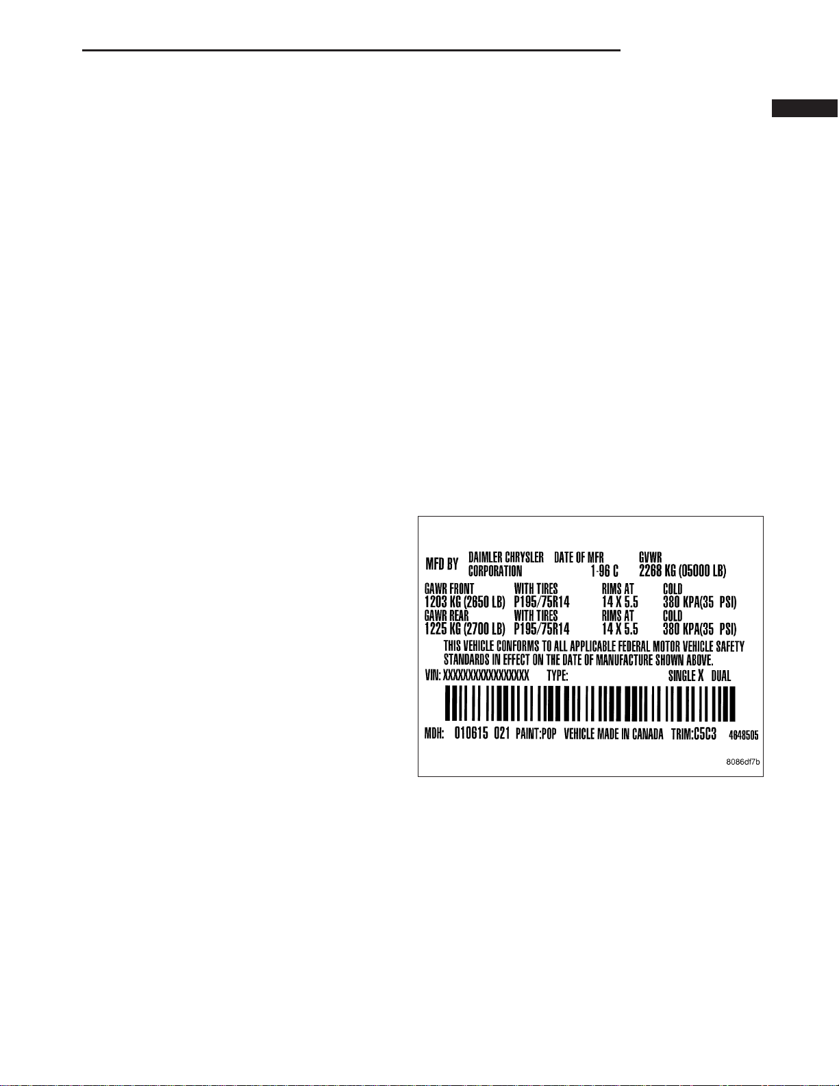
A vehicle certification label is attached to every
DaimlerChrysler Corporation vehicle. The label certifies that the vehicle conforms to all applicable Federal
Motor Vehicle Standards. The label also lists:
• Month and year of vehicle manufacture.
• Gross Vehicle Weight Rating (GVWR). The gross
front and rear axle weight ratings (GAWR’s) are
based on a minimum rim size and maximum cold
tire inflation pressure.
• Vehicle Identification Number (VIN).
• Type of vehicle.
• Type of rear wheels.
• Bar code.
• Month, Day and Hour (MDH) of final assembly.
• Paint and Trim codes.
• Country of origin.
The label is located on the driver-side door shut-face.
FASTENER USAGE
DESCRIPTION
FASTENER USAGE .....................6
THREADED HOLE REPAIR ...............6
METRIC SYSTEM
DESCRIPTION ..........................7
TORQUE REFERENCES
DESCRIPTION ..........................9
Page 3
2 INTRODUCTION ND
VEHICLE IDENTIFICATION NUMBER
DESCRIPTION
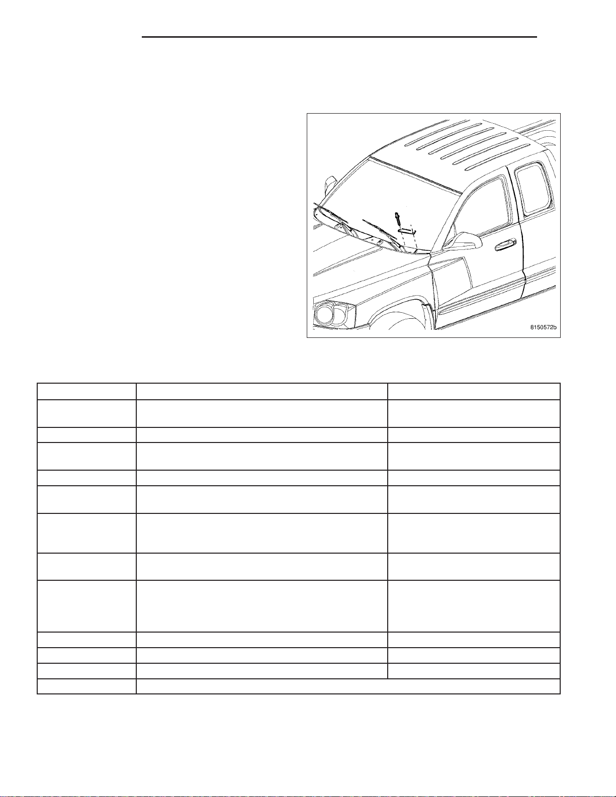
The Vehicle Identification Number (VIN) plate is
attached to the top left side of the instrument panel.
The VIN contains 17 characters that provide data concerning the vehicle. Refer to the decoding chart to
determine the identification of a vehicle.
To protect the consumer from theft and possible fraud
the manufacturer is required to include a Check Digit
at the ninth position of the Vehicle Identification Number. The check digit is used by the manufacturer and
government agencies to verify the authenticity of the
vehicle and official documentation. The formula to use
the check digit is not released to the general public.
VIN DECODING INFORMATION
POSITION INTERPRETATION CODE = DESCRIPTION
1 Country of Origin
2 Make D = Dodge
3 Vehicle Type
4 Gross Vehicle Weight Rating H = 6001-7000 lbs.
5 Vehicle Line
6 Series
7 Body Style
8 Engine
9 Check Digit 0 through 9 or X
10 Model Year 5 = 2005
11 Assembly Plant S = Warren Truck Assembly
12 Thru 17 Vehicle Build Sequence
1 = Manufactured by
DaimlerChrysler Corporation
7 = Truck less Side Airbags
3 = Truck with Side Airbags
E = Dakota 4x2
W = Dakota 4x4
2 = Dakota ST
4 = Dakota SLT/Sport
5 = Dakota LARAMIE/SPORT
2 = Club Cab Dakota
8 = Quad Cab Dakota
K = 3.7L 6 cyl. MPI Gasoline
N = 4.7L 8 cyl. MPI Gasoline
J = 4.7L 8 cyl. MPI High Output
Gasoline
Page 4
ND INTRODUCTION 3
VEHICLE EMISSION CONTROL INFORMATION (VECI) LABEL
DESCRIPTION
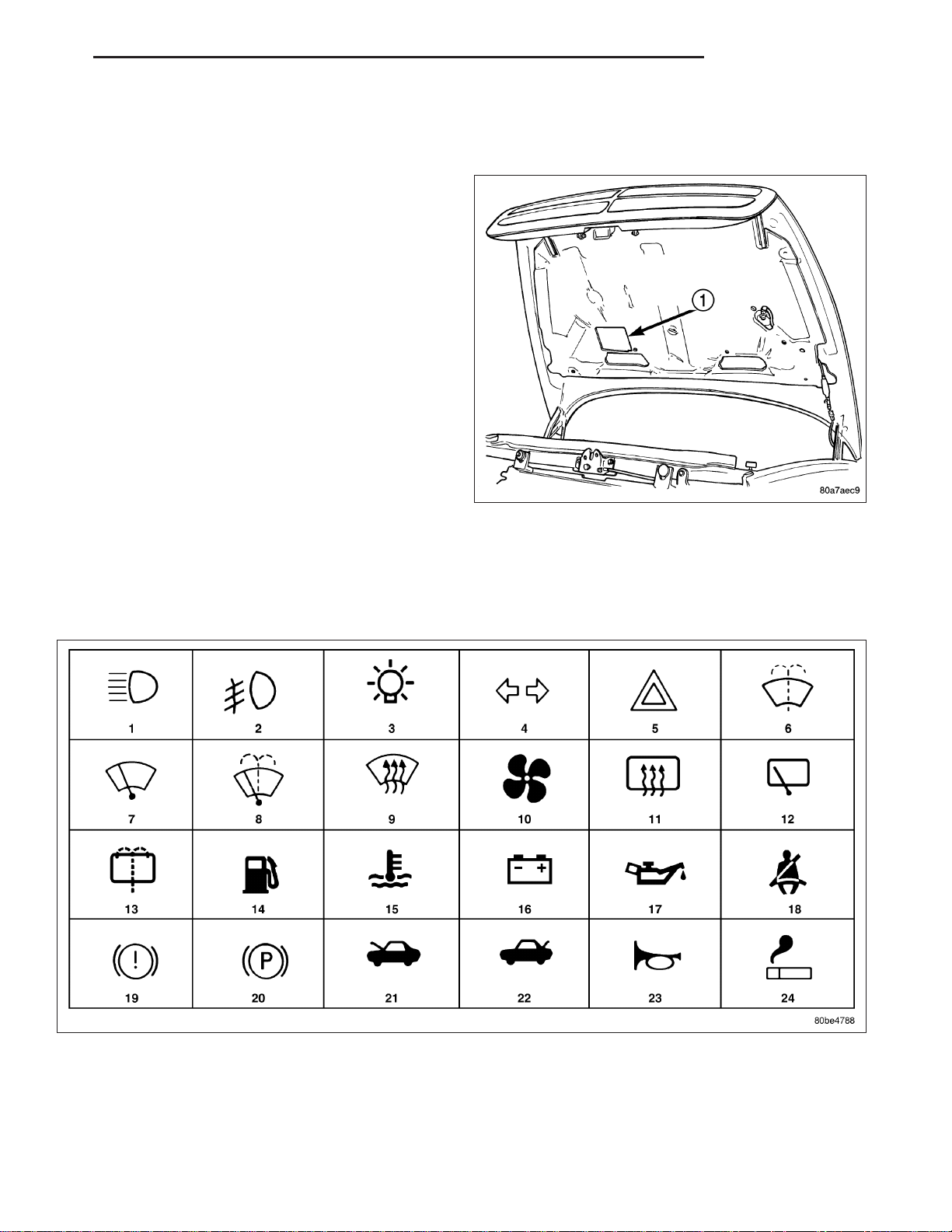
All vehicles are equipped with a combined VECI label.
This label is located in the engine compartment.
The VECI label contains the following:
• Engine family and displacement
• Evaporative family
• Emission control system schematic
• Certification application
• Engine timing specifications (if adjustable)
• Idle speeds (if adjustable)
• Spark plug and gap
The label also contains an engine vacuum schematic.
There are unique labels for vehicles built for sale in
the state of California and the country of Canada.
Canadian labels are written in both the English and
French languages. These labels are permanently
attached and cannot be removed without defacing
information and destroying label.
INTERNATIONAL SYMBOLS
DESCRIPTION
The graphic symbols illustrated in the following International Control and Display Symbols Chart are used to identify
various instrument controls. The symbols correspond to the controls and displays that are located on the instrument
panel.
Page 5
4 INTRODUCTION ND
FASTENER IDENTIFICATION
DESCRIPTION
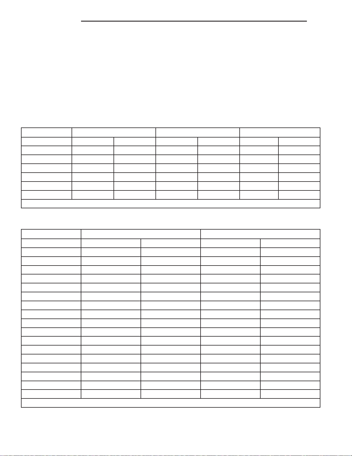
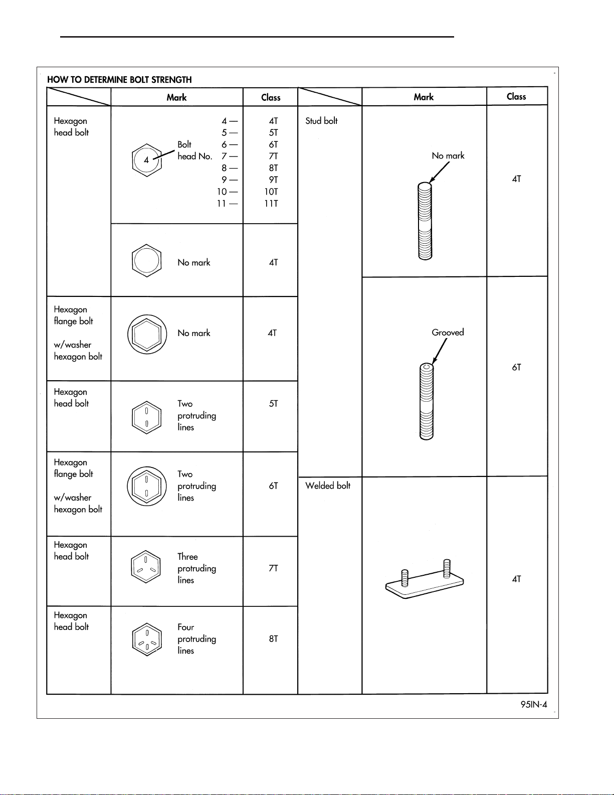
The SAE bolt strength grades range from grade 2 to grade 8. The higher the grade number, the greater the bolt
strength. Identification is determined by the line marks on the top of each bolt head. The actual bolt strength grade
corresponds to the number of line marks plus 2. The most commonly used metric bolt strength classes are 9.8 and
10.9. The metric strength class identification number is imprinted on the head of the bolt. The higher the class
number, the greater the bolt strength. Some metric nuts are imprinted with a single-digit strength class on the nut
face. Refer to the Fastener Identification and Fastener Strength Charts.
Bolt Markings and Torques - Metric
Bolt Markings 8.8/8.9 10.9 12.9
Bolt Dia. N·m Ft. Lbs. N·m Ft. Lbs. N·m Ft. Lbs.
6 12 105* 14 120* 16 12
8 25 250* 32 23 38 28
10 54 40 60 45 74 55
12 95 70 108 80 135 100
14 155 115 175 130 216 160
16 243 180 324 210 324 240
* Inch Lbs.
Bolt Markings and Torques - U. S. Customary
Bolt Markings Grade 5 Grade 8
Bolt Dia. N·m Ft. Lbs N·m Ft. Lbs
1/4 - 20 10 95* 14 125*
1/4 - 28 10 95* 17 150*
5/16 - 18 22 200* 30 270*
5/16 - 24 26 240* 33 300*
3/8-1640305540
3/8-2447356045
7/16-1468508865
7/16-2074559570
1/2 - 13 101 75 135 100
1/2 -20 115 85 150 110
9/16 - 12 135 105 182 135
9/16 - 18 155 115 202 150
5/8 - 11 202 150 263 195
5/8 - 18 215 160 284 210
3/4 - 10 230 170 297 220
3/4 - 16 236 175 304 225
7/8 - 14 405 300 540 400
* Inch Lbs.
Page 6
ND INTRODUCTION 5
Page 7

6 INTRODUCTION ND
FASTENER USAGE
DESCRIPTION
FASTENER USAGE
WARNING: Use of an incorrect fastener may result in component damage or personal injury.
Fasteners and torque specifications references in this Service Manual are identified in metric and SAE format.
During any maintenance or repair procedures, it is important to salvage all fasteners (nuts, bolts, etc.) for reassem-
bly. If the fastener is not salvageable, a fastener of equivalent specification must be used.
THREADED HOLE REPAIR
Most stripped threaded holes can be repaired using a HelicoilT. Follow the vehicle or HelicoilT recommendations for
application and repair procedures.
Page 8
ND INTRODUCTION 7
METRIC SYSTEM
DESCRIPTION
Page 9
8 INTRODUCTION ND
The metric system is based on quantities of one, ten, one hundred, one thousand and one million.
The following chart will assist in converting metric units to equivalent English and SAE units, or vise versa.
CONVERSION FORMULAS AND EQUIVALENT VALUES
MULTIPLY BY TO GET MULTIPLY BY TO GET
in-lbs x
0.11298
ft-lbs x
1.3558
Inches Hg (60° F) x 3.377 = Kilopascals (kPa) kPa x
psi x 6.895 = Kilopascals (kPa) kPa x 0.145 = psi
Inches x 25.4 = Millimeters (mm) mm x
Feet x
0.3048
Yards x
0.9144
mph x
1.6093
Feet/Sec x
0.3048
mph x
0.4470
Kilometers/Hr. (Km/h) x
0.27778
= Newton Meters
(N·m)
= Newton Meters
(N·m)
= Meters (M) M x 3.281 = Feet
= Meters M x
= Kilometers/Hr.
(Km/h)
= Meters/Sec (M/S) M/S x 3.281 = Feet/Sec
= Meters/Sec (M/S) M/S x 2.237 = mph
= Meters/Sec (M/S) M/S x 3.600 Kilometers/Hr. (Km/h)
N·m x 8.851 = in-lbs
N·m x
0.7376
0.2961
0.03937
1.0936
Km/h x
0.6214
= ft-lbs
= Inches Hg
= Inches
= Yards
= mph
COMMON METRIC EQUIVALENTS
1 inch = 25 Millimeters 1 Cubic Inch = 16 Cubic Centimeters
1 Foot = 0.3 Meter 1 Cubic Foot = 0.03 Cubic Meter
1 Yard = 0.9 Meter 1 Cubic Yard = 0.8 Cubic Meter
1 Mile = 1.6 Kilometers
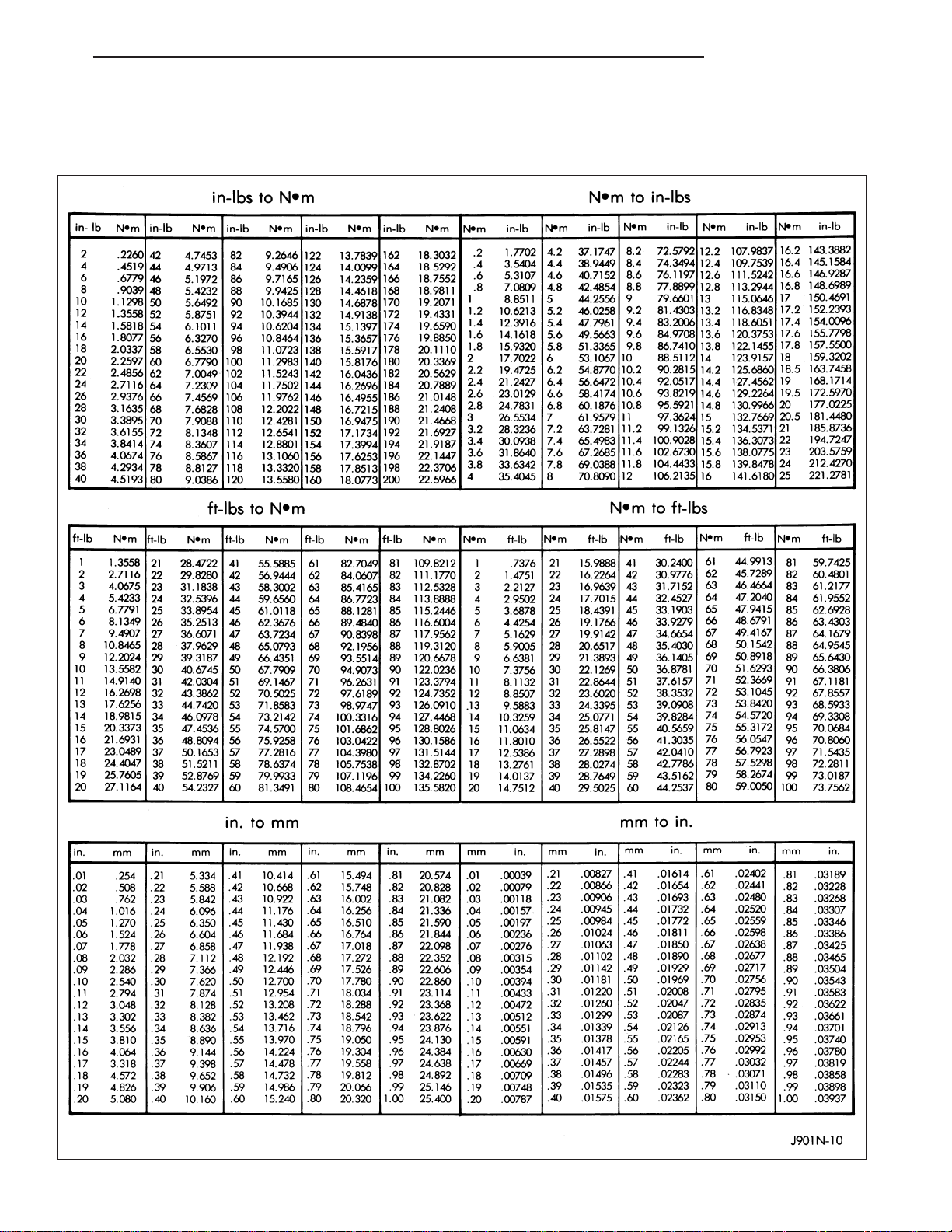
Refer to the Metric Conversion Chart to convert torque values listed in metric Newton- meters (N·m). Also, use the
chart to convert between millimeters (mm) and inches (in.).
Page 10
ND INTRODUCTION 9
TORQUE REFERENCES
DESCRIPTION
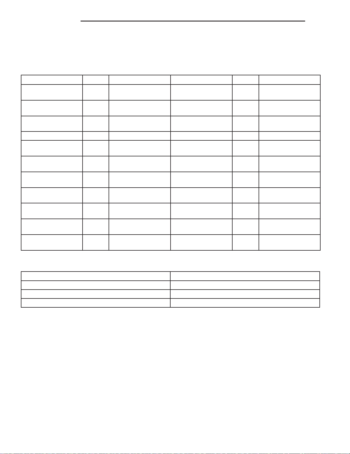
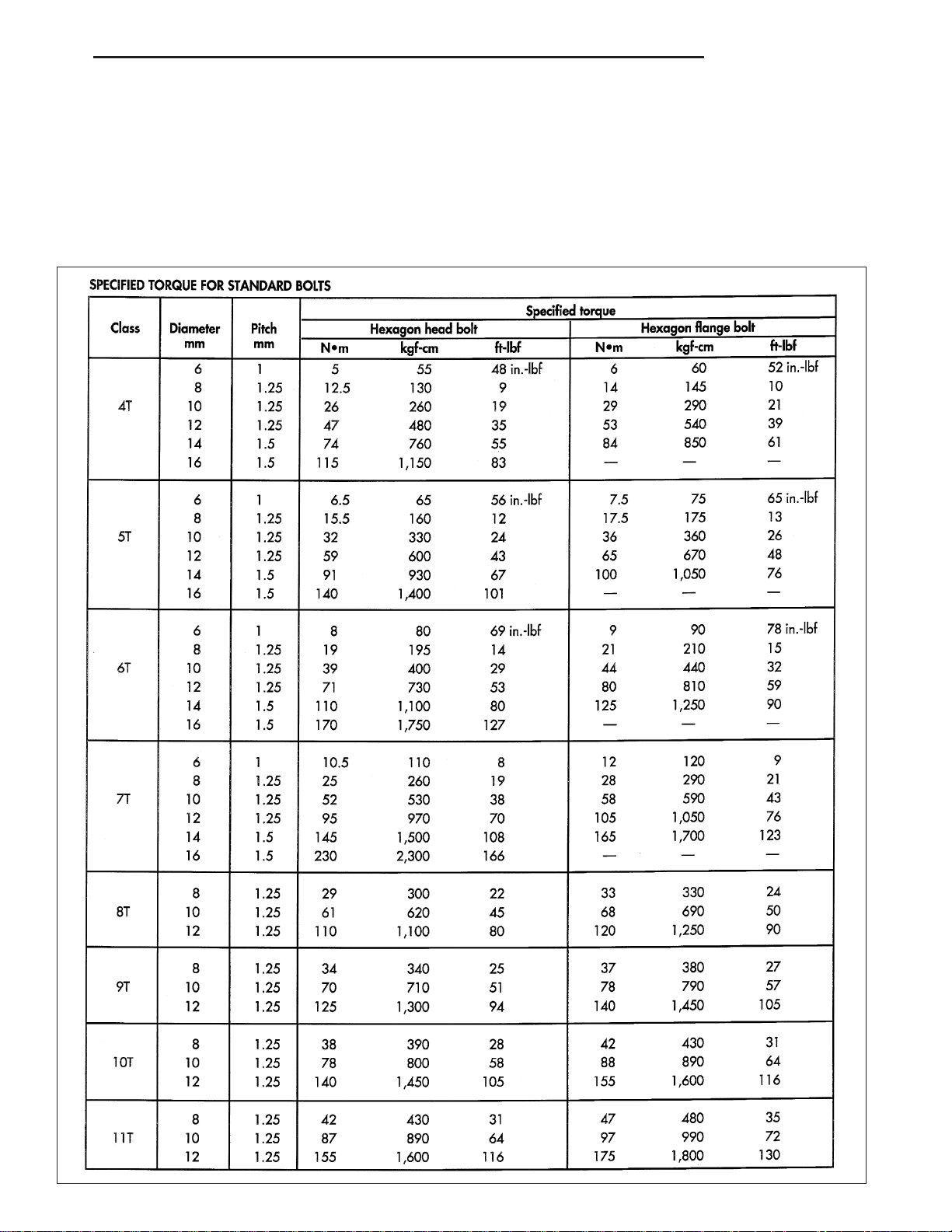
Individual Torque Charts appear within many or the Groups. Refer to the Standard Torque Specifications Chart for
torque references not listed in the individual torque charts.
Page 11

Page 12
ND LUBRICATION & MAINTENANCE 0 - 1
LUBRICATION & MAINTENANCE
TABLE OF CONTENTS
page page
INTERNATIONAL SYMBOLS
DESCRIPTION ..........................1
PARTS & LUBRICANT RECOMMENDATION
DESCRIPTION
LUBRICANT RECOMMENDATIONS .........2
FLUID TYPES .........................2
FLUID TYPES
DESCRIPTION
FUEL REQUIREMENTS ..................3
ENGINE COOLANT .....................4
ENGINE OIL ..........................5
TRANSFER CASE - NV233 ...............6
TRANSFER CASE - NV244 ...............6
AXLE ................................6
POWER STEERING FLUID ...............7
AUTOMATIC TRANSMISSION FLUID ........7
MANUAL TRANSMISSION ................7
OPERATION - AUTOMATIC TRANSMISSION
FLUID ...............................7
INTERNATIONAL SYMBOLS
DESCRIPTION
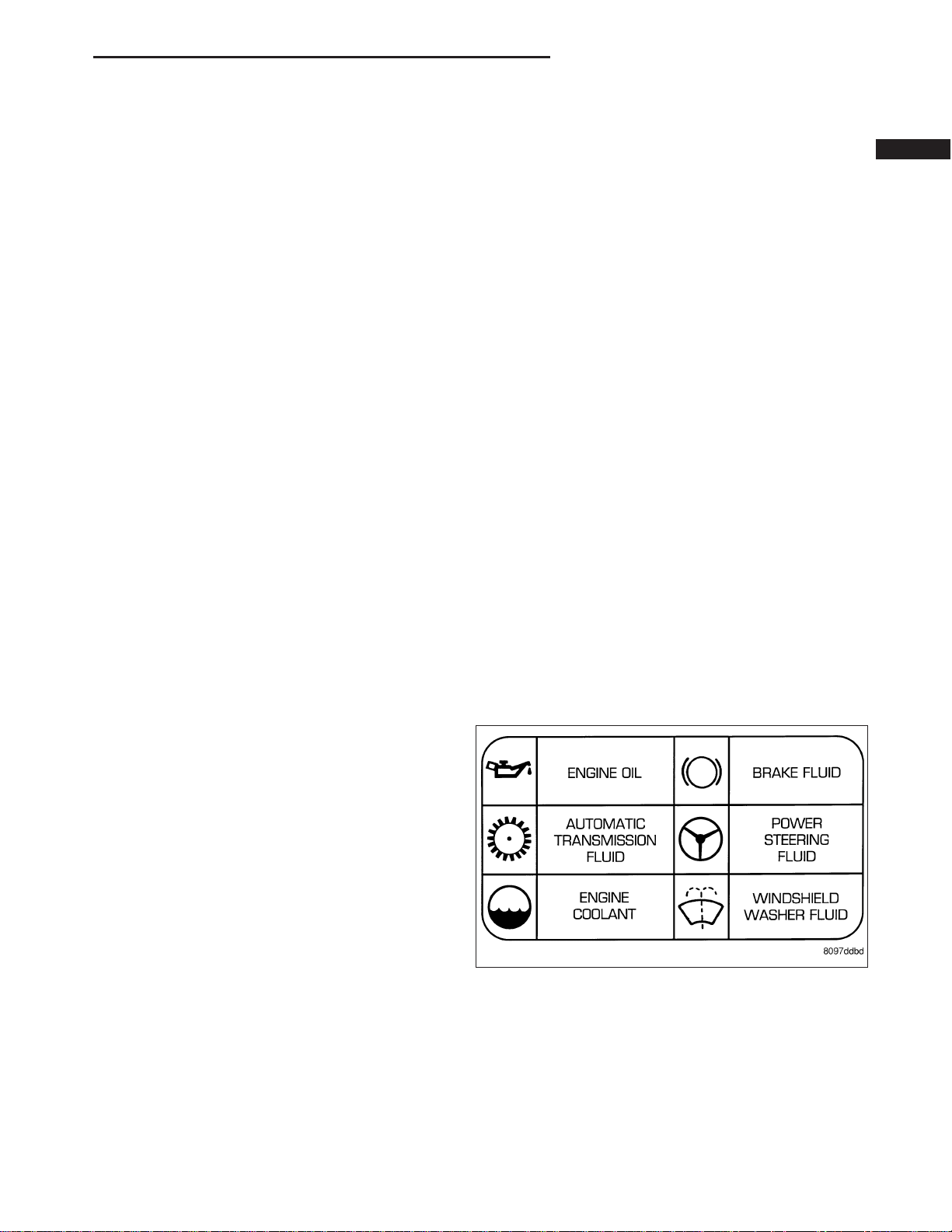
DaimlerChrysler Corporation uses international symbols to identify engine compartment lubricant and fluid
inspection and fill locations.
FLUID CAPACITIES
SPECIFICATIONS
FLUID CAPACITIES .....................8
FLUID FILL/CHECK LOCATIONS
DESCRIPTION ..........................8
MAINTENANCE SCHEDULES
DESCRIPTION
MAINTENANCE SCHEDULES .............9
JUMP STARTING
STANDARD PROCEDURE
JUMP STARTING ......................15
TOWING
STANDARD PROCEDURE
TOWING RECOMMENDATIONS ..........17
FOUR WHEEL DRIVE TOWING ...........18
RECREATIONAL TOWING (BEHIND
MOTORHOME, ETC.) OF 4X4 VEHICLES . . . 19
Page 13
0 - 2 LUBRICATION & MAINTENANCE ND
PARTS & LUBRICANT RECOMMENDATION
DESCRIPTION
LUBRICANT RECOMMENDATIONS
Chassis
Component Fluid, Lubricant, or Genuine Part
Steering Gear & Linkage, Ball
Joints, Prop Shafts & Yokes,
Wheel Bearings
Body
Component Fluid, Lubricant, and Genuine Part
Hinges:
Door & Hood MoparT Engine Oil
Swing Gate MoparT Multi-Purpose Lube NLGI Grade 2 EP, GC-LB
Latches: Door, Hood/Safety
Catch, Swing Gate
Seat Regulator & Track MoparT Multi-Purpose Lube NLGI Grade 2 EP, GC-LB
Lock Cylinders MoparT Lock Cylinder Lube
MoparT Multi-Purpose Lubricant NLGI Grade 2 EP, GC-LB
MoparT Multi-Purpose Lube NLGI Grade 2 EP, GC-LB
FLUID TYPES
When service is required, DaimlerChrysler Corporation recommends that only MoparT brand parts, lubricants and
chemicals be used. MoparT provides the best engineered products for servicing DaimlerChrysler Corporation vehicles.
Only lubricants bearing designations defined by the following organization should be used to service a Chrysler
Corporation vehicle.
• Society of Automotive Engineers (SAE)
• American Petroleum Institute (API)
• National Lubricating Grease Institute (NLGI)
API QUALITY CLASSIFICATION
This symbol on the front of an oil container means
that the oil has been certified by the American Petroleum Institute (API) to meet all the lubrication requirements specified by DaimlerChrysler Corporation.
GEAR LUBRICANTS
SAE ratings also apply to multigrade gear lubricants. In addition, API classification defines the lubricants usage.
Such as API GL-5 and SAE 75W-90.
Page 14

ND LUBRICATION & MAINTENANCE 0 - 3
FLUID TYPES
DESCRIPTION
FUEL REQUIREMENTS
Your engine is designed to meet all emissions regulations and provide excellent fuel economy and performance
when using high quality unleaded “regular” gasoline having an octane rating of 87. The routine use of premium
gasoline is not recommended. Under normal conditions the use of premium fuel will not provide a benefit over high
quality regular gasolines and in some circumstances may result in poorer performance.
Light spark knock at low engine speeds is not harmful to your engine. However, continued heavy spark knock at
high speeds can cause damage and immediate service is required. Engine damage resulting from operation with a
heavy spark knock may not be covered by the new vehicle warranty.
Poor quality gasoline can cause problems such as hard starting, stalling and hesitations. If you experience these
symptoms, try another brand of gasoline before considering service for the vehicle.
Over 40 auto manufacturers world-wide have issued and endorsed consistent gasoline specifications (the Worldwide
Fuel Charter, WWFC) to define fuel properties necessary to deliver enhanced emissions, performance and durability
for your vehicle. We recommend the use of gasolines that meet the WWFC specifications if they are available.
REFORMULATED GASOLINE
Many areas of the country require the use of cleaner burning gasoline referred to as “reformulated” gasoline. Reformulated gasoline contain oxygenates, and are specifically blended to reduce vehicle emissions and improve air
quality.
We strongly support the use of reformulated gasoline. Properly blended reformulated gasoline will provide excellent
performance and durability for the engine and fuel system components.
GASOLINE/OXYGENATE BLENDS
Some fuel suppliers blend unleaded gasoline with oxygenates such as 10% ethanol, MTBE, and ETBE. Oxygenates
are required in some areas of the country during the winter months to reduce carbon monoxide emissions. Fuels
blended with these oxygenates may be used in your vehicle.
CAUTION: DO NOT use gasoline containing METHANOL. Gasoline containing methanol may damage critical
fuel system components.
MMT IN GASOLINE
MMT is a manganese-containing metallic additive that is blended into some gasoline to increase octane. Gasoline
blended with MMT provide no performance advantage beyond gasoline of the same octane number without MMT.
Gasoline blended with MMT reduce spark plug life and reduce emission system performance in some vehicles. We
recommend that gasolines free of MMT be used in your vehicle. The MMT content of gasoline may not be indicated
on the gasoline pump; therefore, you should ask your gasoline retailer whether or not his/her gasoline contains
MMT.
It is even more important to look for gasoline without MMT in Canada because MMT can be used at levels higher
than allowed in the United States. MMT is prohibited in Federal and California reformulated gasoline.
SULFUR IN GASOLINE
If you live in the northeast United States, your vehicle may have been designed to meet California low emission
standards with Cleaner-Burning California reformulated gasoline with low sulfur. If such fuels are not available in
states adopting California emission standards, your vehicles will operate satisfactorily on fuels meeting federal specifications, but emission control system performance may be adversely affected. Gasoline sold outside of California is
permitted to have higher sulfur levels which may affect the performance of the vehicle’s catalytic converter. This may
cause the Malfunction Indicator Lamp (MIL), Check Engine or Service Engine Soon light to illuminate. We recommend that you try a different brand of unleaded gasoline having lower sulfur to determine if the problem is fuel
related prior to returning your vehicle to an authorized dealer for service.
Page 15

0 - 4 LUBRICATION & MAINTENANCE ND
CAUTION: If the Malfunction Indicator Lamp (MIL), Check Engine or Service Engine Soon light is flashing,
immediate service is required; see on-board diagnostics system section.
MATERIALS ADDED TO FUEL
All gasoline sold in the United States and Canada are required to contain effective detergent additives. Use of additional detergents or other additives is not needed under normal conditions.
FUEL SYSTEM CAUTIONS
CAUTION: Follow these guidelines to maintain your vehicle’s performance:
• The use of leaded gas is prohibited by Federal law. Using leaded gasoline can impair engine performance,
damage the emission control system, and could result in loss of warranty coverage.
• An out-of-tune engine, or certain fuel or ignition malfunctions, can cause the catalytic converter to overheat. If
you notice a pungent burning odor or some light smoke, your engine may be out of tune or malfunctioning and
may require immediate service. Contact your dealer for service assistance.
• When pulling a heavy load or driving a fully loaded vehicle when the humidity is low and the temperature is
high, use a premium unleaded fuel to help prevent spark knock. If spark knock persists, lighten the load, or
engine piston damage may result.
• The use of fuel additives which are now being sold as octane enhancers is not recommended. Most of these
products contain high concentrations of methanol. Fuel system damage or vehicle performance problems
resulting from the use of such fuels or additives is not the responsibility of DaimlerChrysler Corporation and
may not be covered under the new vehicle warranty.
NOTE: Intentional tampering with emissions control systems can result in civil penalties being assessed
against you.
ENGINE COOLANT
WARNING: ANTIFREEZE IS AN ETHYLENE GLYCOL BASE COOLANT AND IS HARMFUL IF SWALLOWED OR
INHALED. IF SWALLOWED, DRINK TWO GLASSES OF WATER AND INDUCE VOMITING. IF INHALED, MOVE
TO FRESH AIR AREA. SEEK MEDICAL ATTENTION IMMEDIATELY. DO NOT STORE IN OPEN OR UNMARKED
CONTAINERS. WASH SKIN AND CLOTHING THOROUGHLY AFTER COMING IN CONTACT WITH ETHYLENE
GLYCOL. KEEP OUT OF REACH OF CHILDREN. DISPOSE OF GLYCOL BASE COOLANT PROPERLY, CONTACT YOUR DEALER OR GOVERNMENT AGENCY FOR LOCATION OF COLLECTION CENTER IN YOUR
AREA.
WARNING: DO NOT OPEN A COOLING SYSTEM WHEN THE ENGINE IS AT OPERATING TEMPERATURE OR
HOT UNDER PRESSURE, PERSONAL INJURY CAN RESULT. AVOID RADIATOR COOLING FAN WHEN
ENGINE COMPARTMENT RELATED SERVICE IS PERFORMED, PERSONAL INJURY CAN RESULT.
CAUTION: Use of Propylene Glycol based coolants is not recommended, as they provide less freeze protection and less corrosion protection.
The cooling system is designed around the coolant. The coolant must accept heat from engine metal, in the cylinder
head area near the exhaust valves and engine block. Then coolant carries the heat to the radiator where the tube/
fin radiator can transfer the heat to the air.
The use of aluminum cylinder blocks, cylinder heads, and water pumps requires special corrosion protection.
MoparT Antifreeze/Coolant, 5 Year/100,000 Mile Formula (MS-9769), or the equivalent ethylene glycol base coolant
with organic corrosion inhibitors (called HOAT, for Hybrid Organic Additive Technology) is recommended. This coolant offers the best engine cooling without corrosion when mixed with 50% Ethylene Glycol and 50% distilled water
to obtain a freeze point of -37°C (-35°F). If it loses color or becomes contaminated, drain, flush, and replace with
fresh properly mixed coolant solution.
CAUTION: Do not use coolant additives that are claimed to improve engine cooling.
Page 16

ND LUBRICATION & MAINTENANCE 0 - 5
CAUTION: MoparT Antifreeze/Coolant, 5 Year/100,000 Mile Formula (MS-9769) may not be mixed with any
other type of antifreeze. Mixing of coolants other than specified non-HOAT or other HOAT coolant, may
result in engine damage that may not be covered under the new vehicle warranty, and decreased corrosion
protection.
COOLANT PERFORMANCE
The required ethylene-glycol (antifreeze) and distilled water mixture depends upon climate and vehicle operating
conditions. The coolant performance of various mixtures follows:
Pure Distilled Water - Distilled water can absorb more heat than a mixture of water and ethylene-glycol. This is for
purpose of heat transfer only. Water also freezes at a higher temperature and allows corrosion.
100 percent Ethylene-Glycol - The corrosion inhibiting additives in ethylene-glycol need the presence of distilled
water to dissolve. Without water, additives form deposits in system. These act as insulation causing temperature to
rise to as high as 149°C (300°F). This temperature is hot enough to melt plastic and soften solder. The increased
temperature can result in engine detonation. In addition, 100 percent ethylene-glycol freezes at -22°C (-8°F).
50/50 Ethylene-Glycol and Distilled Water - Is the recommended mixture, it provides protection against freezing to
-37°C (-34°F). The antifreeze concentration must always be a minimum of 44 percent, year-round in all climates. If
percentage is lower, engine parts may be eroded by cavitation. Maximum protection against freezing is provided
with a 68 percent antifreeze concentration, which prevents freezing down to -67.7°C (-90°F). A higher percentage
will freeze at a warmer temperature. Also, a higher percentage of antifreeze can cause the engine to overheat
because specific heat of antifreeze is lower than that of water.
CAUTION: Richer antifreeze mixtures cannot be measured with normal field equipment and can cause problems associated with 100 percent ethylene-glycol.
ENGINE OIL
WARNING: NEW OR USED ENGINE OIL CAN BE IRRITATING TO THE SKIN. AVOID PROLONGED OR
REPEATED SKIN CONTACT WITH ENGINE OIL. CONTAMINANTS IN USED ENGINE OIL, CAUSED BY INTERNAL COMBUSTION, CAN BE HAZARDOUS TO YOUR HEALTH. THOROUGHLY WASH EXPOSED SKIN WITH
SOAP AND WATER. DO NOT WASH SKIN WITH GASOLINE, DIESEL FUEL, THINNER, OR SOLVENTS,
HEALTH PROBLEMS CAN RESULT. DO NOT POLLUTE, DISPOSE OF USED ENGINE OIL PROPERLY. CONTACT YOUR DEALER OR GOVERNMENT AGENCY FOR LOCATION OF COLLECTION CENTER IN YOUR
AREA.
When service is required, DaimlerChrysler Corporation recommends that only MoparT brand parts, lubricants and
chemicals be used. MoparT provides the best engineered products for servicing DaimlerChrysler Corporation vehicles.
Only lubricants bearing designations defined by the following organization should be used.
• Society of Automotive Engineers (SAE)
• American Petroleum Institute (API)
• National Lubricating Grease Institute (NLGI)
• Association des Constructeurs Européens d’ Automobiles (European Automobile Manufacturers Association)
(ACEA)
API SERVICE GRADE CERTIFIED
Use an engine oil that is API Certified. MOPART provides engine oils, that meet or exceed this requirement.
Page 17
0 - 6 LUBRICATION & MAINTENANCE ND
SAE VISCOSITY
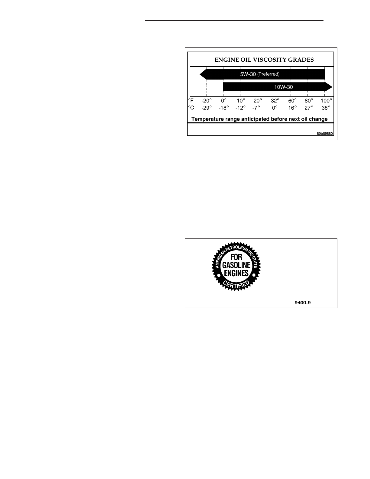
An SAE viscosity grade is used to specify the viscosity
of engine oil. Use only engine oils with multiple viscosities such as 5W-30 or 10W-30. These are specified
with a dual SAE viscosity grade which indicates the
cold-to-hot temperature viscosity range. Select an
engine oil that is best suited to your particular temperature range and variation.
ACEA Categories
For countries that use the ACEA European Oil Categories for Service Fill Oils, use engine oils that meet the requirements of ACEA A1/B1, A2/B2, or A3/B3.
ENERGY CONSERVING OIL
An Energy Conserving type oil is recommended for gasoline engines. The designation of ENERGY CONSERVING
is located on the label of an engine oil container.
CONTAINER IDENTIFICATION
Standard engine oil identification notations have been
adopted to aid in the proper selection of engine oil.
The identifying notations are located on the front label
of engine oil plastic bottles and the top of engine oil
cans.
This symbol means that the oil has been certified by
the American Petroleum Institute (API). DiamlerChrysler only recommend API Certified engine oils.
Use MoparT engine oil or equivalent.
TRANSFER CASE - NV233
Recommended lubricant for the NV233 transfer case is MoparT ATF +4, Automatic Transmission Fluid.
TRANSFER CASE - NV244
Recommended lubricant for the NV244 transfer case is MoparT ATF +4, Automatic Transmission Fluid.
AXLE
NOTE: DaimlerChrysler recommends MoparT lubricants or lubricants of equal quality.
FRONT AXLE
• C205F - MoparT Gear Lubricant 75W-90
REAR AXLE
• 8 1/4 - MoparT Synthetic Gear Lubricant 75W-140
• 9 1/4 - MoparT Synthetic Gear Lubricant 75W-140
Page 18

ND LUBRICATION & MAINTENANCE 0 - 7
POWER STEERING FLUID
MoparT ATF +4, Automatic Transmission Fluid is required in the power steering system. Substitute fluids can induce
power steering system failure.
MoparT ATF +4, Automatic Transmission Fluid when new is red in color. The ATF is dyed red so it can be identified
from other fluids used in the vehicle such as engine oil or antifreeze. The red color is not permanent and is not an
indicator of fluid condition. As the vehicle is driven, the ATF will begin to look darker in color and may eventually
become brown. This is normal. ATF+4 also has a unique odor that may change with age. Consequently, odor and
color cannot be used to indicate the fluid condition or the need for a fluid change.
AUTOMATIC TRANSMISSION FLUID
NOTE: Refer to Service Procedures in this group for fluid level checking procedures.
MoparT ATF +4, Automatic Transmission Fluid is the recommended fluid for DaimlerChrysler automatic transmissions.
Dexron II fluid IS NOT recommended. Clutch chatter can result from the use of improper fluid.
MoparT ATF +4, Automatic Transmission Fluid when new is red in color. The ATF is dyed red so it can be identified
from other fluids used in the vehicle such as engine oil or antifreeze. The red color is not permanent and is not an
indicator of fluid condition. As the vehicle is driven, the ATF will begin to look darker in color and may eventually
become brown. This is normal. ATF+4 also has a unique odor that may change with age. Consequently, odor and
color cannot be used to indicate the fluid condition or the need for a fluid change.
FLUID ADDITIVES
DaimlerChrysler strongly recommends against the addition of any fluids to the transmission, other than those automatic transmission fluids listed above. Exceptions to this policy are the use of special dyes to aid in detecting fluid
leaks.
Various “special” additives and supplements exist that claim to improve shift feel and/or quality. These additives and
others also claim to improve converter clutch operation and inhibit overheating, oxidation, varnish, and sludge.
These claims have not been supported to the satisfaction of DaimlerChrysler and these additives must not be
used. The use of transmission “sealers” should also be avoided, since they may adversely affect the integrity of
transmission seals.
MANUAL TRANSMISSION
NOTE: DaimlerChrysler recommends MoparT lubricants or lubricants of equal quality.
• G238 - MoparT ATF+4
OPERATION - AUTOMATIC TRANSMISSION FLUID
The automatic transmission fluid is selected based upon several qualities. The fluid must provide a high level of
protection for the internal components by providing a lubricating film between adjacent metal components. The fluid
must also be thermally stable so that it can maintain a consistent viscosity through a large temperature range. If the
viscosity stays constant through the temperature range of operation, transmission operation and shift feel will remain
consistent. Transmission fluid must also be a good conductor of heat. The fluid must absorb heat from the internal
transmission components and transfer that heat to the transmission case.
Page 19
0 - 8 LUBRICATION & MAINTENANCE ND
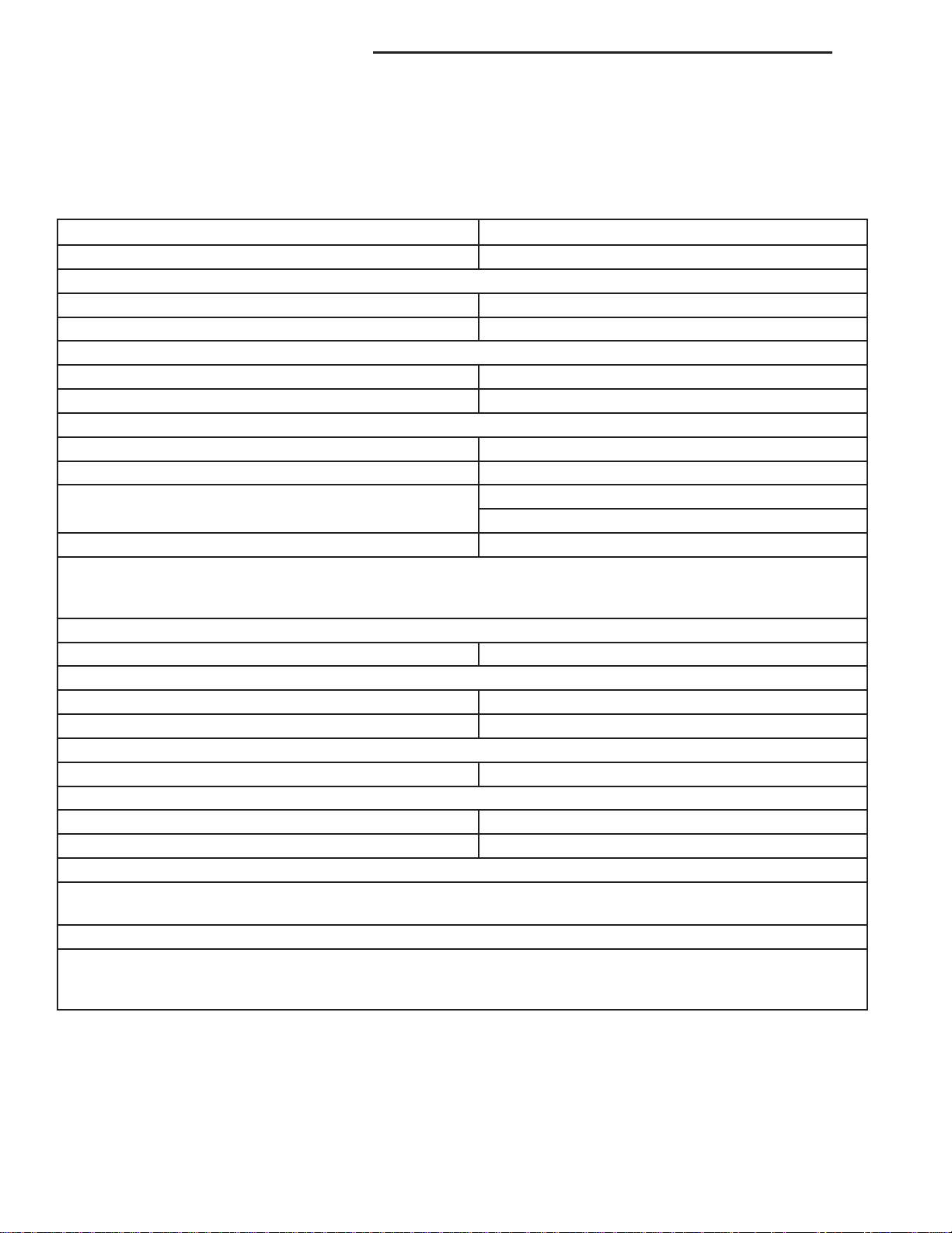
FLUID CAPACITIES
SPECIFICATIONS
FLUID CAPACITIES
DESCRIPTION SPECIFICATION
FUEL TANK 25 U.S. Gallons (95 Liters)****
ENGINE OIL
3.7L - with Filter 4.7L (5.0 qts.)
4.7L - with Filter 5.6L (6.0 qts.)
COOLING SYSTEM
3.7L 15.4L (16.2 qts.)***
4.7L 15.4L (16.2 qts.)***
AUTOMATIC TRANSMISSION
Service Fill - 42RLE 3.8L (4.0 qts.)
O-haul Fill - 42RLE 8.3L (17.6 pts.)
Service Fill - 545RFE
O-haul Fill - 545RFE 13.33L (28.0 pts.)
Dry fill capacity Depending on type and size of internal cooler, length and inside diameter of cooler lines, or use of
an auxiliary cooler, these figures may vary. (Refer to 21 - TRANSMISSION/AUTOMATIC/FLUID - STANDARD
PROCEDURE)
MANUAL TRANSMISSION
G238 2.2L (4.65 pts.)
TRANSFER CASE
NV233 1.18L (2.5 pts.)
NV244 1.35L (2.85 pts.)
FRONT AXLE
C205F 1.66L (56 oz.)
REAR AXLE
8 1/4 in. 2.07L (70 oz.)
9 1/4 in. 2.13L (72 oz.)
*** Includes 0.9L (1.0 qts.) for coolant reservoir.
****Nominal refill capacities are shown. A variation may be observed from vehicle to vehicle due to manufacturing
tolerance and refill procedure.
Power Steering
Power steering fluid capacities are dependent on engine/chassis options as well as steering gear/cooler options.
Depending on type and size of internal cooler, length and inside diameter of cooler lines, or use of an auxiliary
cooler, these capacities may vary.
2WD - 5.2 L (11 pts.)
4WD - 6.2 L (13 pts.)
FLUID FILL/CHECK LOCATIONS
DESCRIPTION
The fluid check/fill points and lubrication locations are located in each applicable Sections.
Page 20

ND LUBRICATION & MAINTENANCE 0 - 9
MAINTENANCE SCHEDULES
DESCRIPTION
MAINTENANCE SCHEDULES
There are two maintenance schedules that show the required service for your vehicle.
First is Schedule “B”. It is for vehicles that are operated under the conditions that are listed below and at the
beginning of the schedule.
• Day or night temperatures are below 32° F (0° C).
• Stop and go driving.
• Extensive engine idling.
• Driving in dusty conditions.
• Short trips of less than 10 miles (16 km).
• More than 50% of your driving is at sustained high speeds during hot weather, above 90° F (32° C).
• Trailer towing.
• Taxi, police, or delivery service (commercial service).
• Off-road or desert operation.
• If equipped for and operating with E-85 (ethanol) fuel.
NOTE: If ANY of these apply to you then change your engine oil every 3,000 miles (5 000 km) or 3 months,
whichever comes first and follow schedule “B” of the (Maintenance Schedules( section of this manual.
NOTE: If ANY of these apply to you then change your coolant every 102,000 miles (163 000 km) or 60
months, whichever comes first and follow schedule “B” of the (Maintenance Schedules( section of this
manual.
NOTE: Most vehicles are operated under the conditions listed for Schedule (B(.
Second is Schedule “A”. It is for vehicles that are not operated under any of the conditions listed under Schedule
9B9.
Use the schedule that best describes your driving conditions. Where time and mileage are listed, follow the interval
that occurs first.
NOTE: Under no circumstances should oil change intervals exceed 6000 miles (10 000 km) or 6 months
whichever comes first.
CAUTION: Failure to perform the required maintenance items may result in damage to the vehicle.
At Each Stop for Fuel
• Check the engine oil level about 5 minutes after a fully warmed engine is shut off. Checking the oil level while
the vehicle is on level ground will improve the accuracy of the oil level reading. Add oil only when the level is
at or below the ADD or MIN mark.
• Check the windshield washer solvent and add if required.
Once a Month
• Check tire pressure and look for unusual wear or damage.
• Inspect the battery and clean and tighten the terminals as required.
• Check the fluid levels of coolant reservoir, brake master cylinder, and transmission and add as needed.
• Check all lights and all other electrical items for correct operation.
Page 21
0 - 10 LUBRICATION & MAINTENANCE ND
At Each Oil Change
• Change the engine oil filter.
• Inspect the exhaust system.
• Inspect the brake hoses.
• Inspect the CV joints (if equipped) and front suspension components.
• Check the automatic transmission fluid level.
• Check the coolant level, hoses, and clamps.
Schedule “B”
Follow schedule “B” if you usually operate your vehicle under one or more of the following conditions.
• Day or night temperatures are below 32° F (0° C).
• Stop and go driving.
• Extensive engine idling.
• Driving in dusty conditions.
• Short trips of less than 10 miles (16 km).
• More than 50% of your driving is at sustained high speeds during hot weather, above 90° F (32° C).
• Trailer towing.
• Taxi, police, or delivery service (commercial service).
• Off-road or desert operation.
• If equipped for and operating with E-85 (ethanol) fuel.
NOTE: If ANY of these apply to you then change your engine oil every 3,000 miles (5 000 km) or 3 months,
whichever comes first and follow schedule “B” of the (Maintenance Schedules( section of this manual.
NOTE: If ANY of these apply to you then change your coolant every 102,000 miles (163 000 km) or 60
months, whichever comes first and follow schedule “B” of the (Maintenance Schedules( section of this
manual.
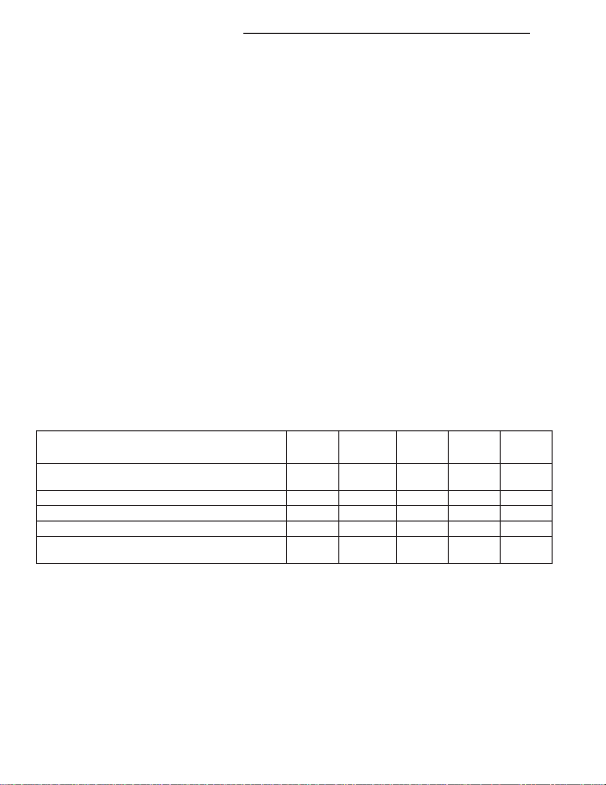
Miles 3,000 6,000 9,000 12,000 15,000
(Kilometers) (5 000) (10 000) (14 000) (19 000) (24 000)
Change engine oil and engine oil filter, or at 3 months
whichever comes first.
Rotate tires. X X
Change rear axle fluid. X
Change front axle fluid (4X4). X
Inspect engine air cleaner filter, replace if
necessary.
XXXXX
X
Page 22
ND LUBRICATION & MAINTENANCE 0 - 11
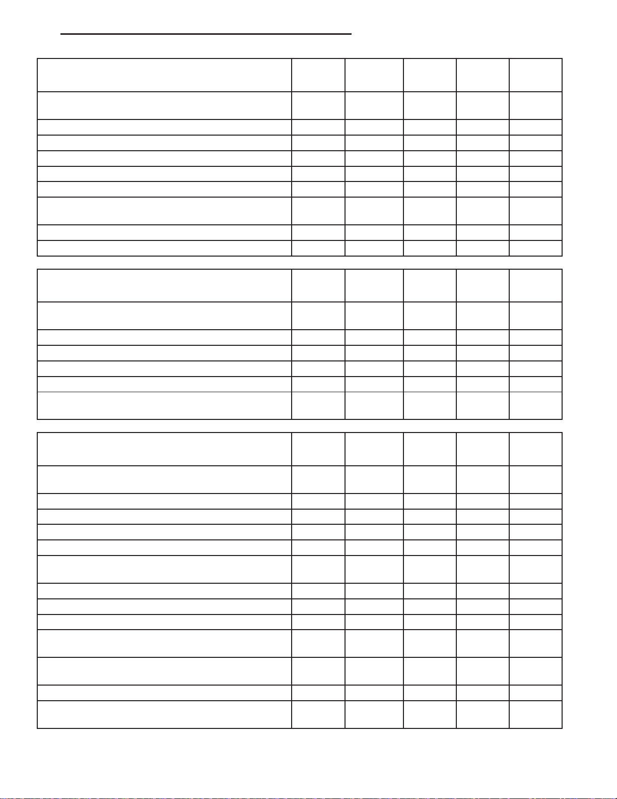
Miles 18,000 21,000 24,000 27,000 30,000
(Kilometers) (29 000) (34 000) (38 000) (43 000) (48 000)
Change engine oil and engine oil filter, or at 3 months
whichever comes first.
Rotate tires. X X X
Change rear axle fluid. X
Change front axle fluid (4X4). X
Check transfer case fluid level (4X4). X
Inspect brake linings. X
Inspect engine air cleaner filter, replace if
necessary.
Replace spark plugs. X
Inspect PCV valve, replace as necessary. X
Miles 33,000 36,000 39, 000 42,000 45,000
(Kilometers) (53 000) (58 000) (62 000) (67 000) (72 000)
Change engine oil and engine oil filter, or at 3 months
whichever comes first.
Rotate tires. X X
Change rear axle fluid. X
Change front axle fluid (4X4). X
Inspect brake linings. X
Inspect engine air cleaner filter, replace if
necessary.
XXXXX
X
XXXXX
X
Miles 48,000 51,000 54,000 57,000 60,000
(Kilometers) (77 000) (82 000) (86 000) (91 000) (96 000)
Change engine oil and engine oil filter, or at 3 months
whichever comes first.
Rotate tires. X X X
Change rear axle fluid. X
Change front axle fluid (4X4). X
Inspect brake linings. X
Inspect engine air cleaner filter, replace if
necessary.
Replace spark plugs. X
Inspect PCV valve, replace as necessary. X
Inspect auto tension drive belt and replace if required. X
Drain and refill automatic transmission fluid, change
filter (3.7L).
Drain and refill automatic transmission fluid and
change main sump filter (4.7L).
Inspect transfer case fluid (4X4). X
Flush and replace engine coolant at 60 months, or
102, 000 miles (163 000 km) whichever comes first.
XXXXX
X
X
X
Page 23
0 - 12 LUBRICATION & MAINTENANCE ND
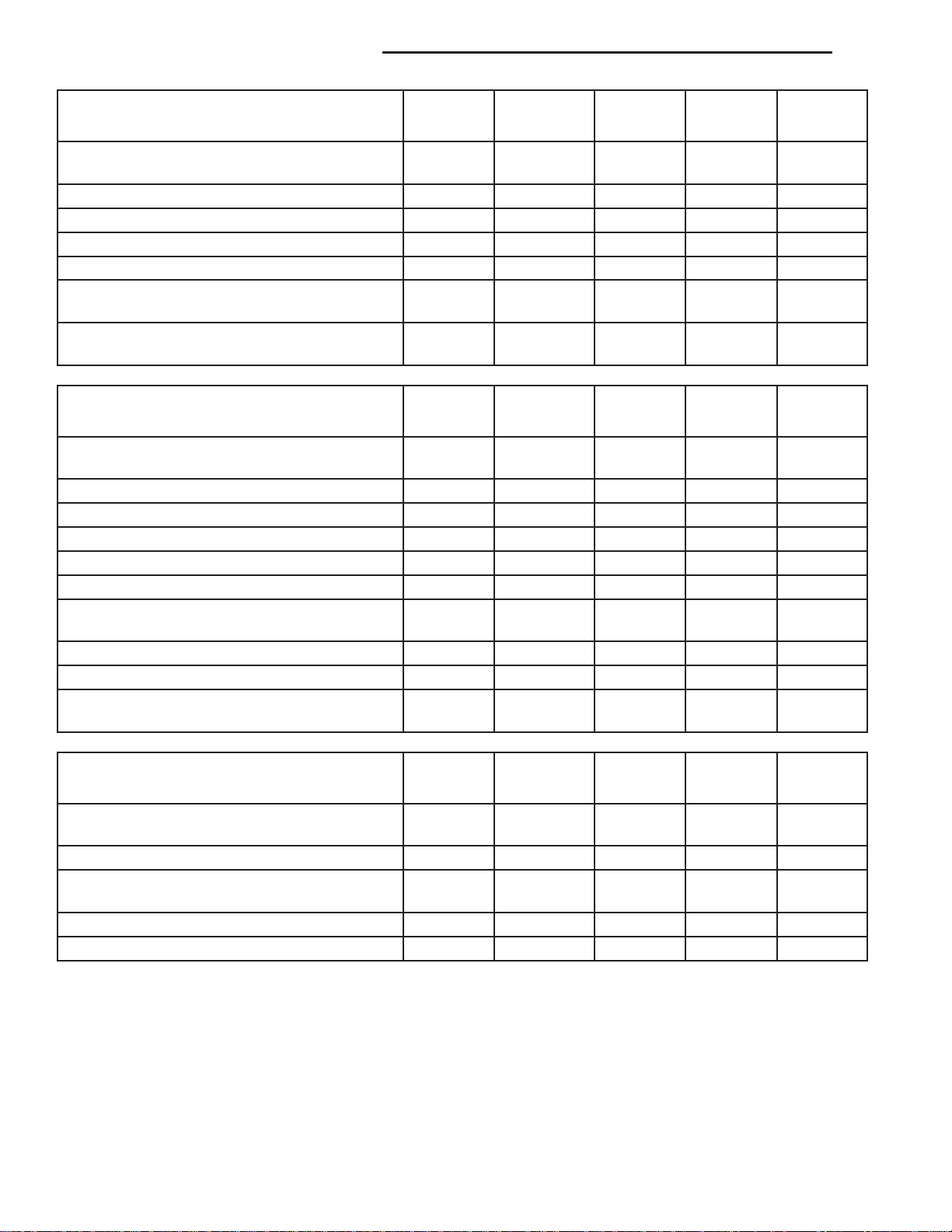
Miles 63,000 66,000 69,000 72,000 75,000
(Kilometers) (101 000) (106 000) (110 000) (115 000) (120 000)
Change engine oil and engine oil filter, or at 3
months whichever comes first.
Rotate tires. X X
Change rear axle fluid. X
Change front axle fluid (4X4). X
Inspect brake linings. X
Inspect engine air cleaner filter, replace if
necessary.
Inspect auto tension drive belt and replace if
required.
Miles 78,000 81,000 84,000 87,000 90,000
(Kilometers ) (125 000) (130 000) (134 000) (139 000) (144 000)
Change engine oil and engine oil filter, or at 3
months whichever comes first.
Rotate tires. X X X
Change rear axle fluid. X
Change front axle fluid (4X4). X
Check transfer case fluid level (4X4). X
Inspect brake linings. X
Inspect engine air cleaner filter, replace if
necessary.
Replace spark plugs. X
Inspect PCV valve, replace as necessary. X
Inspect auto tension drive belt and replace if
required.
XXXX
X
X
XXXXX
X
X
Miles 93,000 96,000 99,000 100,000 102,000
(Kilometers) (149 000) (154 000) (158 000) (160 000) (163 000)
Change engine oil and engine oil filter, or at 3
months whichever comes first.
Rotate tires. X X
Flush and replace engine coolant, if not done
at 60 months.
Change rear axle fluid. X
Change front axle fluid (4X4). X
XXX X
X
Page 24
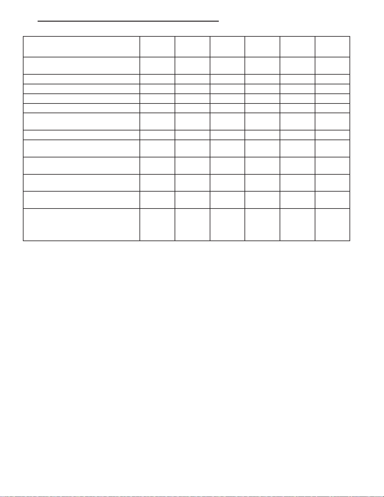
ND LUBRICATION & MAINTENANCE 0 - 13
Miles 105,000 108,000 111,000 114,000 117,000 120,000
(Kilometers) (168 000) (173 000) (178 000) (182 000) (187 000) (192 000)
Change engine oil and engine oil filter,
or at 3 months whichever comes first.
Rotate tires. X X X
Change rear axle fluid. X X
Change front axle fluid (4X4). X X
Inspect brake linings. X
Inspect engine air cleaner filter,
replace if necessary.
Replace spark plugs. X
Inspect PCV valve, replace as
necessary.
Inspect auto tension drive belt and
replace if required.‡
Drain and refill transfer case fluid
(4X4).
Drain and refill automatic transmission
fluid, change filter (3.7L).
Drain and refill automatic transmission
fluid and change main sump filter and
spin-on cooler return filter if equipped.
(4.7L).
XXXXXX
XX
X
XX
X
X
X
* This applies only if your vehicle is used for police, taxi, fleet, or frequent trailer towing.
Inspection and service should also be performed anytime a malfunction is observed or suspected. Retain all
receipts.
Page 25
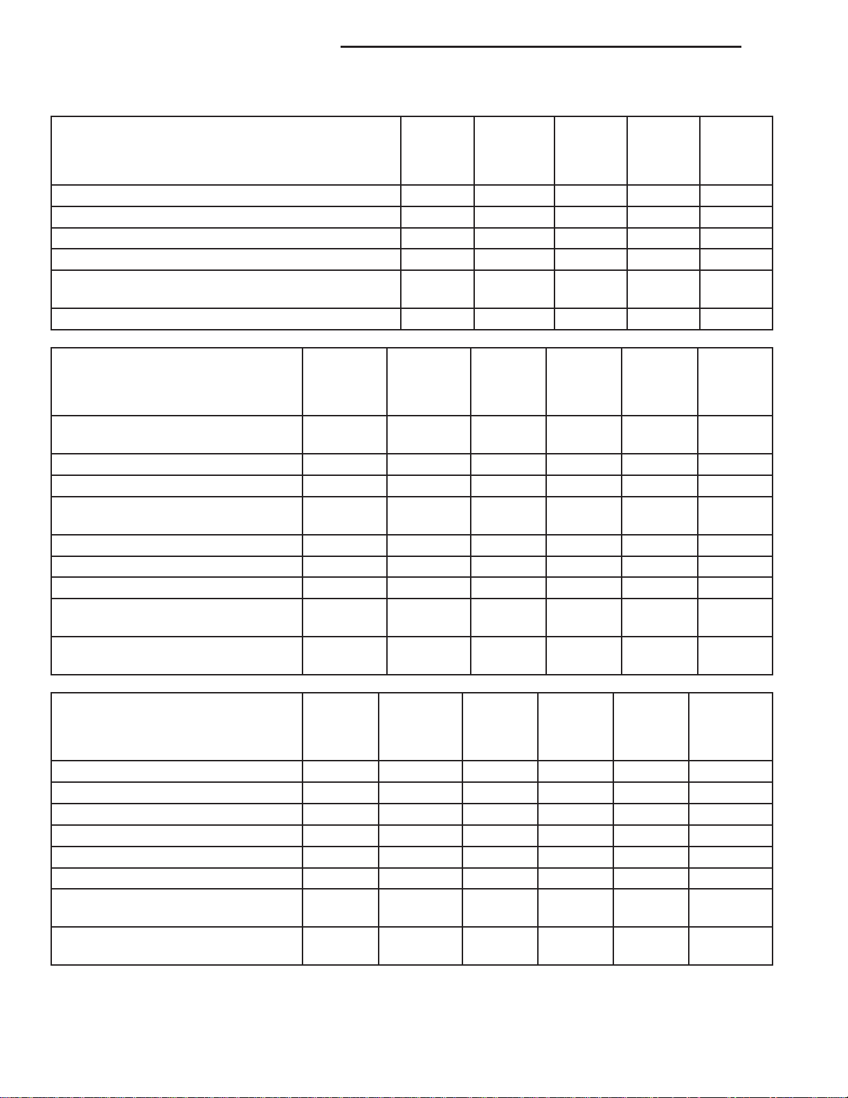
0 - 14 LUBRICATION & MAINTENANCE ND
Schedule “A”
Miles 6,000 12,000 18,000 24,000 30,000
(Kilometers) (10 000) (19 000) (29 000) (38 000) (48 000)
[Months] [6] [12] [18] [24] [30]
Change engine oil and engine oil filter. X X X X X
Rotate tires. X X X X X
Check transfer case fluid level (4X4). X
Inspect brake linings. X
Inspect engine air cleaner filter, replace as
necessary.
Replace spark plugs. X
Miles 36,000 42,000 48,000 54000 60,000 66,000
(Kilometers) (58 000) (67 000) (77 000) (84 000) (96 000) (106 000)
[Months] [36] [42] [48] [54] [60] [66]
Change engine oil and engine oil
filter.
Rotate tires. X X X X X X
Check transfer case fluid level (4X4). X
Flush and replace engine coolant at
60 months, regardless of mileage.
Inspect brake linings. X X
Replace engine air cleaner filter. X
Replace spark plugs. X
Inspect PCV valve, replace as
necessary.
Inspect auto tension drive belt and
replace if required.
XXXX
X
X
X
X
X
X
Miles 72,000 78,000 84,000 90,000 96,000 100,000
(Kilometers) (115 000) (125 000) (134 000) (144 000) (154 000) (160 000)
[Months] [72] [78] [84] [90] [96]
Change engine oil and engine oil filter. X X X X X
Rotate tires. X X X X X X
Check transfer case fluid level (4X4). X
Inspect brake linings. X X
Replace engine air cleaner filter. X
Replace spark plugs. X
Inspect PCV valve, replace as
necessary.
Inspect auto tension drive belt and
replace if required.‡
X
X
Page 26
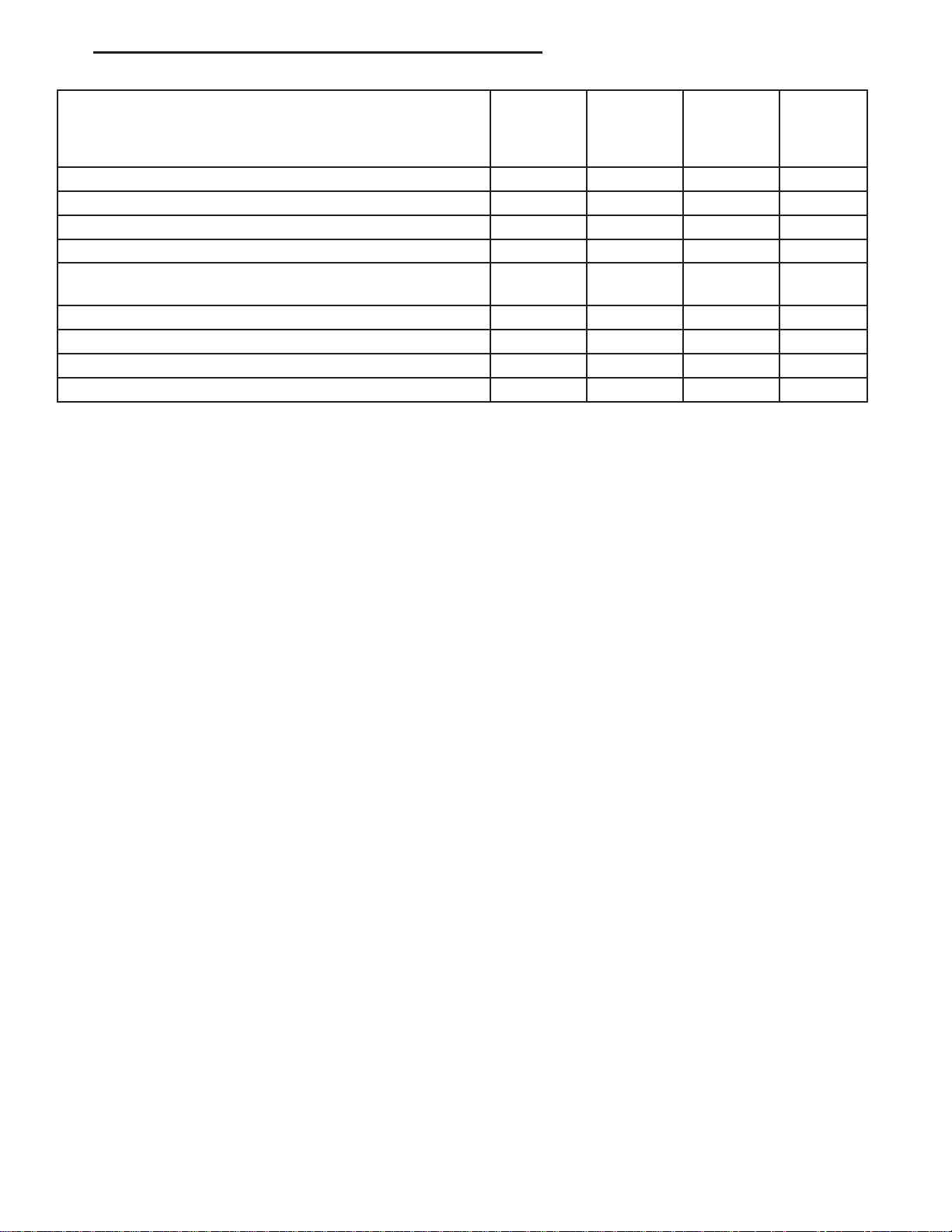
ND LUBRICATION & MAINTENANCE 0 - 15
Miles 102,000 108,000 114,000 120,000
(Kilometers) (163 000) (173 000) (182 000) (192 000)
[Months] [102] [108] [114] [120]
Change engine oil and engine oil filter. X X X X
Rotate tires. X X X X
Drain and refill tranfer case fluid (4X4). X
Flush and replace engine coolant, if not done at 60 months. X
Flush and replace engine coolant, if not done at 102,000
miles (163 000 km)
Inspect brake linings. X
Inspect engine air cleaner filter, replace as necessary. X
Replace spark plugs. X
Inspect PCV valve, replace as necessary. X
‡ This maintenance is not required if previously performed.
Inspection and service should also be performed anytime a malfunction is observed or suspected. Retain all
receipts.
WARNING:
You can be badly injured working on or around a motor vehicle. Do only that service work for which you
have the knowledge and the right equipment. If you have any doubt about your ability to perform a service
job, take your vehicle to a competent mechanic.
X
JUMP STARTING
STANDARD PROCEDURE
JUMP STARTING
WARNING: REVIEW ALL SAFETY PRECAUTIONS AND WARNINGS IN THE BATTERY SYSTEM SECTION OF
THE SERVICE MANUAL. (Refer to 8 - ELECTRICAL/BATTERY SYSTEM/BATTERY - STANDARD PROCEDURE)
• DO NOT JUMP START A FROZEN BATTERY, PERSONAL INJURY CAN RESULT.
• IF EQUIPPED, DO NOT JUMP START WHEN MAINTENANCE FREE BATTERY INDICATOR DOT IS YELLOW
OR BRIGHT COLOR.
• DO NOT JUMP START A VEHICLE WHEN THE BATTERY FLUID IS BELOW THE TOP OF LEAD PLATES.
• DO NOT ALLOW JUMPER CABLE CLAMPS TO TOUCH EACH OTHER WHEN CONNECTED TO A
BOOSTER SOURCE.
• DO NOT USE OPEN FLAME NEAR BATTERY.
• REMOVE METALLIC JEWELRY WORN ON HANDS OR WRISTS TO AVOID INJURY BY ACCIDENTAL ARC-
ING OF BATTERY CURRENT.
• WHEN USING A HIGH OUTPUT BOOSTING DEVICE, DO NOT ALLOW BATTERY VOLTAGE TO EXCEED 16
VOLTS. REFER TO INSTRUCTIONS PROVIDED WITH DEVICE BEING USED.
FAILURE TO FOLLOW THESE INSTRUCTIONS MAY RESULT IN PERSONAL INJURY.
CAUTION: When using another vehicle as a booster, do not allow vehicles to touch. Electrical systems can
be damaged on either vehicle.
Page 27
0 - 16 LUBRICATION & MAINTENANCE ND
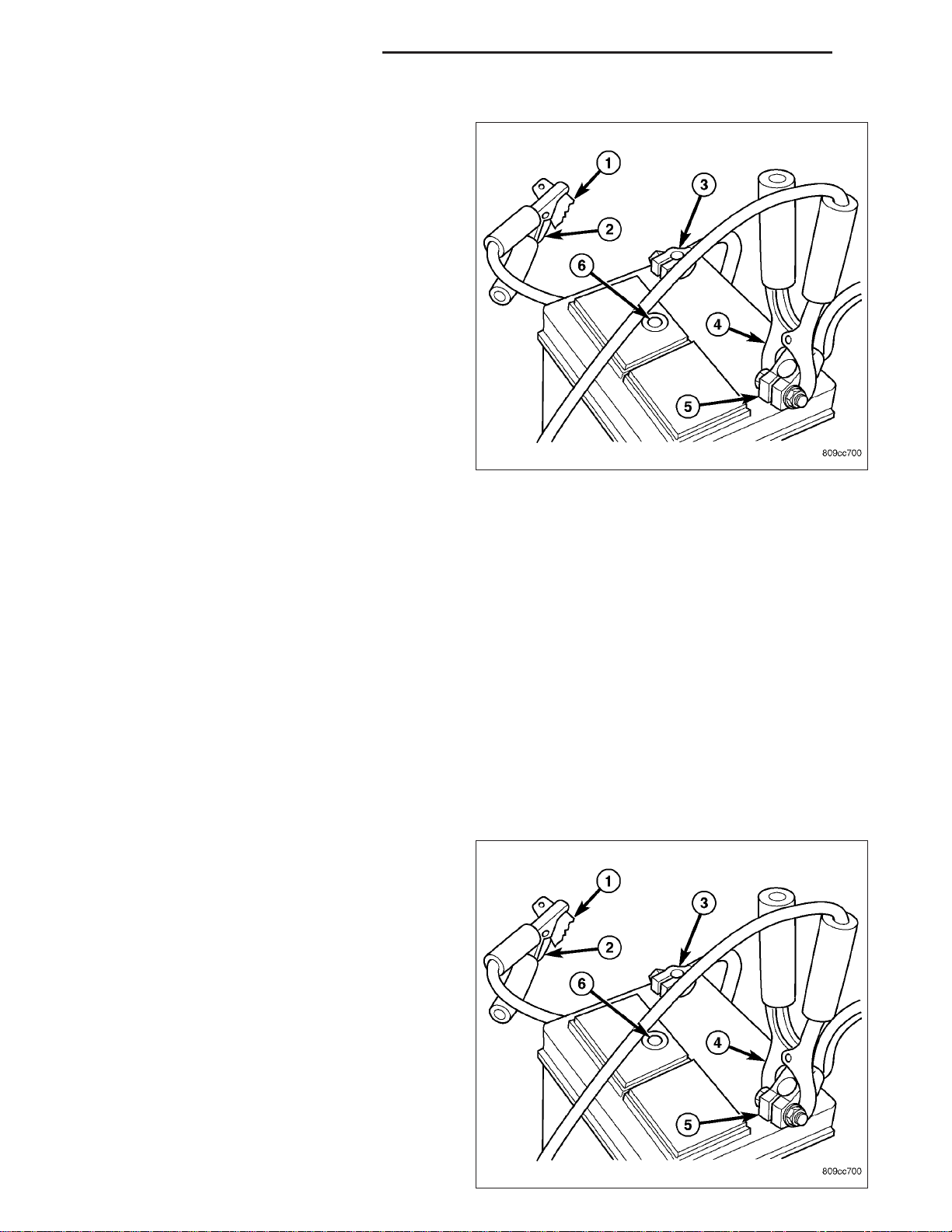
TO JUMP START A DISABLED VEHICLE:
1. Raise hood on disabled vehicle and visually inspect
engine compartment for:
• Battery cable clamp condition, clean if necessary.
• Frozen battery.
• Yellow or bright color test indicator, if equipped.
• Low battery fluid level.
• Generator drive belt condition and tension.
• Fuel fumes or leakage, correct if necessary.
CAUTION: If the cause of starting problem on disabled vehicle is severe, damage to booster vehicle
charging system can result.
2. When using another vehicle as a booster source,
park the booster vehicle within cable reach. Turn
off all accessories, set the parking brake, place the
automatic transmission in PARK or the manual
transmission in NEUTRAL and turn the ignition
OFF.
3. On disabled vehicle, place gear selector in park or neutral and set park brake. Turn off all accessories.
4. Connect jumper cables to booster battery. RED clamp (4) to positive terminal (+). BLACK clamp (2) to negative
(3) terminal (-). DO NOT allow clamps at opposite end of cables to touch, electrical arc will result. Review all
warnings in this procedure.
5. On disabled vehicle, connect RED jumper cable (4) clamp to positive (+) terminal. Connect BLACK jumper cable
clamp to engine ground (1) as close to the ground cable attaching point as possible.
6. Start the engine in the vehicle which has the booster battery, let the engine idle a few minutes, then start the
engine in the vehicle with the discharged battery.
CAUTION: Do not crank starter motor on disabled vehicle for more than 15 seconds, starter will overheat
and could fail.
7. Allow battery in disabled vehicle to charge to at least 12.4 volts (75% charge) before attempting to start engine.
If engine does not start within 15 seconds, stop cranking engine and allow starter to cool (15 min.), before cranking again.
DISCONNECT CABLE CLAMPS AS FOLLOWS:
• Disconnect BLACK cable clamp (2) from engine
ground (1) on disabled vehicle.
• When using a booster vehicle, disconnect
BLACK cable clamp (2) from battery negative
terminal (3). Disconnect RED cable clamp (4)
from battery positive terminal (5).
• Disconnect RED cable clamp (4) from battery
positive terminal (4) on disabled vehicle.
Page 28
ND LUBRICATION & MAINTENANCE 0 - 17
TOWING
STANDARD PROCEDURE
TOWING RECOMMENDATIONS
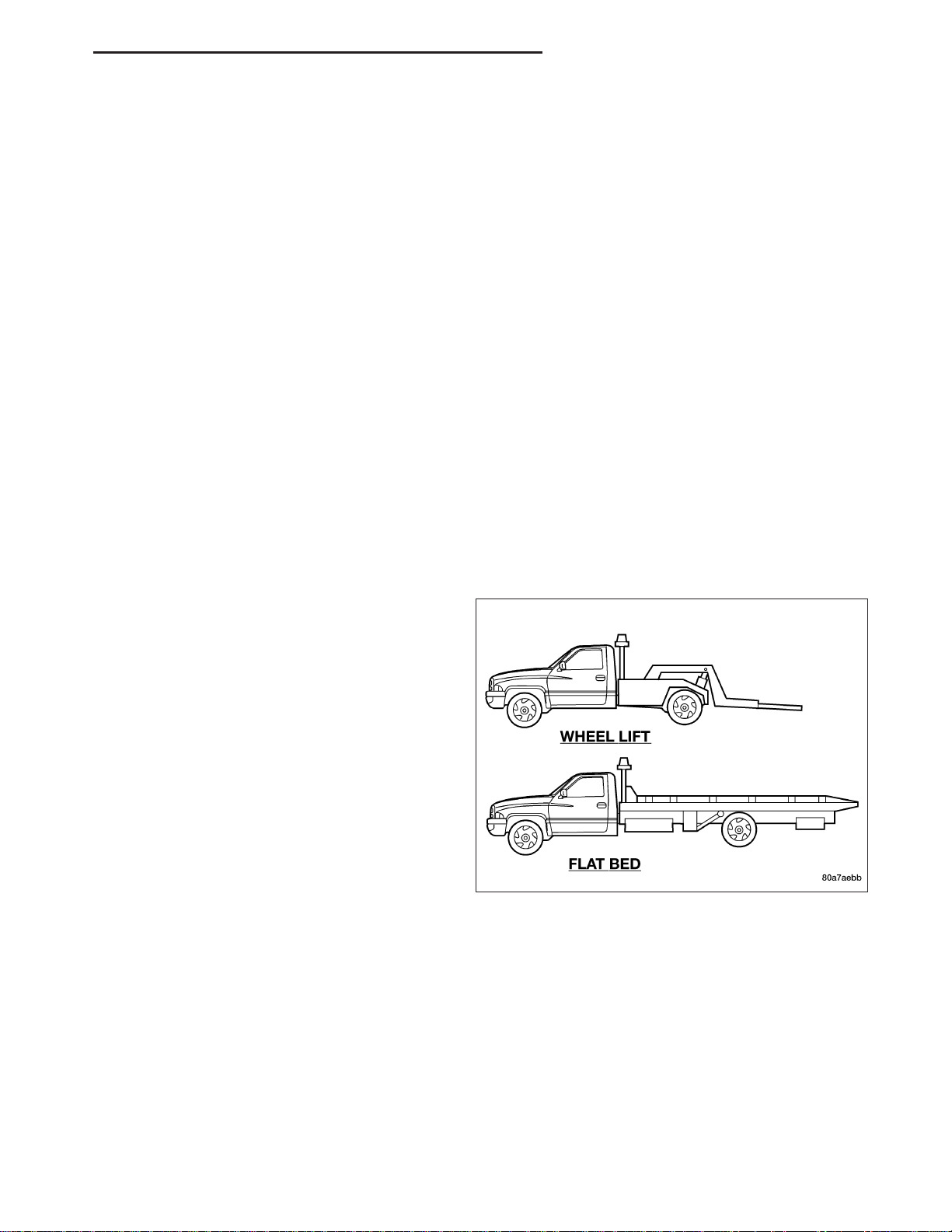
A vehicle equipped with SAE approved wheel lift-type towing equipment can be used to tow all vehicles. When
towing a 4WD vehicle using a wheel-lift towing device, use tow dollies under the opposite end of the vehicle. A
vehicle with flatbed device can also be used to transport a disabled vehicle.
Four-Wheel Drive Vehicles
The manufacturer recommends towing with all wheels OFF the ground. Acceptable methods are to tow the vehicle
on a flatbed or with one end of the vehicle raised and the opposite end on a towing dolly.
Two-Wheel Drive Vehicles
Provided that the transmission is operable, tow with the transmission in Neutral and the ignition key in the OFF
position along with the front wheels raised and the rear wheels on the ground. The speed must not exceed 30 mph
(50 km/h) and the distance must not exceed 15 miles (25 km).
If the vehicle is to be towed more than 15 miles (25 km ), it must be towed on a flatbed, or with the rear wheels
raised and the front wheels on the ground, or with the front end raised and the rear wheels on a towing dolly.
NOTE: Towing the vehicle at more than 30 mph (50 km/h) or for more than 15 miles (25 km ) can cause
severe transmission damage.
SAFETY PRECAUTIONS
CAUTION: The following safety precautions must
be observed when towing a vehicle:
• Secure loose and protruding parts.
• Always use a safety chain system that is inde-
pendent of the lifting and towing equipment.
• Do not allow towing equipment to contact the
disabled vehicle’s fuel tank.
• Do not allow anyone under the disabled vehicle
while it is lifted by the towing device.
• Do not allow passengers to ride in a vehicle
being towed.
• Always observe state and local laws regarding
towing regulations.
• Do not tow a vehicle in a manner that could
jeopardize the safety of the operator, pedestrians
or other motorists.
• Do not attach tow chains, T-hooks, or J-hooks to a bumper, steering linkage, drive shafts or a non-reinforced
frame hole.
• Do not tow a heavily loaded vehicle. Use a flatbed device to transport a loaded vehicle.
GROUND CLEARANCE
CAUTION: If vehicle is towed with wheels removed, install lug nuts to retain brake drums or rotors.
A towed vehicle should be raised until lifted wheels are a minimum 100 mm (4 in) from the ground. Be sure there
is adequate ground clearance at the opposite end of the vehicle, especially when towing over rough terrain or steep
rises in the road.
RAMP ANGLE
If a vehicle with flatbed towing equipment is used, the approach ramp angle should not exceed 15 degrees.
Page 29

0 - 18 LUBRICATION & MAINTENANCE ND
TOWING WHEN KEYS ARE NOT AVAILABLE
When the vehicle is locked and keys are not available, use a flat bed hauler. A wheel-lift device can be used on
4WD vehicles provided all the wheels are lifted off the ground using tow dollies.
FOUR WHEEL DRIVE TOWING
Chrysler Corporation recommends that a vehicle be transported on a flat-bed device. A Wheel-lift device can be
used provided all the wheels are lifted off the ground using tow dollies.
WARNING: WHEN TOWING A DISABLED VEHICLE AND THE DRIVE WHEELS ARE SECURED IN A WHEEL
LIFT OR TOW DOLLIES, ENSURE THE TRANSMISSION IS IN THE PARK POSITION.
CAUTION: Many vehicles are equipped with air dams, spoilers, and/or ground effect panels. To avoid component damage, a wheel-lift towing vehicle or a flat-bed hauling vehicle is recommended.
FOUR WHEEL DRIVE TOWING – REAR END LIFTED
WARNING: ENSURE VEHICLE IS ON A LEVEL SURFACE OR THE WHEELS ARE BLOCKED TO PREVENT
VEHICLE FROM ROLLING.
1. Attach wheel lift device to front wheels.
2. Place the transmission in neutral.
3. Raise the front of the vehicle off the ground and install tow dollies under front wheels.
4. Attach wheel lift device to rear wheels and raise vehicle to towing position.
5. Attach safety chains to frame rails. Route chains so not to interfere with tail pipe when vehicle is lifted.
6. Turn the ignition switch to the OFF position to unlock the steering wheel.
CAUTION: Do not use steering column lock to secure steering wheel during towing operation.
7. Secure steering wheel in straight ahead position with a clamp device designed for towing.
8. Place the transmission in park.
FOUR WHEEL DRIVE TOWING – FRONT END LIFTED
WARNING: ENSURE VEHICLE IS ON A LEVEL SURFACE OR THE WHEELS ARE BLOCKED TO PREVENT
VEHICLE FROM ROLLING.
1. Attach wheel lift device to rear wheels.
2. Place the transmission in neutral.
3. Raise the rear of the vehicle off the ground and install tow dollies under rear wheels.
4. Attach wheel lift device to front wheels and raise vehicle to towing position.
5. Attach the safety chains.
CAUTION: Do not use steering column lock to secure steering wheel during towing operation.
6. Turn the ignition switch to the OFF position to unlock the steering wheel.
7. Secure steering wheel in straight ahead position with a clamp device designed for towing.
8. Place the transmission in park.
Page 30

ND LUBRICATION & MAINTENANCE 0 - 19
RECREATIONAL TOWING (BEHIND MOTORHOME, ETC.) OF 4X4 VEHICLES
WARNING: You or others could be injured if you leave the vehicle unattended with the transfer case in the
Neutral (N) position without first fully engaging the parking brake. The transfer case Neutral (N) position
disengages both the front and rear driveshafts from the powertrain and will allow the vehicle to move
despite the transmission position. The parking brake should always be applied when the driver is not in the
vehicle.
CAUTION: Internal damage to the transfer case will occur if a front or rear wheel lift is used when recreational towing.
NOTE: Because of the design of the transfer cases only vehicles equipped with a NV 244 Generation II
transfer case should be used for recreational towing.
NOTE: The NV 244 Generation II transfer case must be shifted into Neutral (N) for recreational towing. The
Neutral (N) selection button is located on the lower left hand corner of the 4WD Control Switch. Shifts into
and out of transfer case Neutral (N) can take place with the selector switch in any mode position.
NOTE: If the vehicle is to be towed for multiple days or one day for an eight hour or above duration, disconnect and isolate the battery to prevent discharge do to the illumination of the odometer and PRNDL
light. After the battery negative cable is reinstalled the radio clock and stations will need to be reset.
Shifting into Neutral (N)
Use the following procedure to prepare your vehicle for recreational towing.
CAUTION: It is necessary to follow these steps to be certain that the transfer case is fully in Neutral (N)
before recreational towing to prevent damage to internal parts.
1. Bring vehicle to a complete stop.
2. Shut engine OFF.
3. Place ignition key in the ON position.
4. Depress brake pedal.
5. Shift automatic transmission to Neutral (N) or depress clutch on manual transmission.
6. Using the point of a ballpoint pen or similar object, depress the recessed transfer case Neutral (N) button for
4 seconds.
7. After shift is completed and the Neutral (N) light comes on release Neutral (N) button.
8. Start engine.
9. Shift automatic transmission into Reverse (R).
10. Release brake pedal for five seconds and ensure that there is no vehicle movement.
11. Repeat steps 9 and 10 with the transmission in Drive (D).
12. Shut engine OFF and place ignition key to the unlocked OFF position.
13. Shift automatic transmission into Park (P).
14. Attach vehicle to tow vehicle with tow bar.
NOTE: Items 1 through 5 are requirements that must be met prior to depressing the Neutral (N) selection
button, and must continue to be met until the 4 seconds elaspes and the shift has been completed. If any
of these requirements (with the exception of 3 - Key ON) are not met prior to depressing the Neutral (N)
button or are no longer met during the 4 second timer, then the Neutral (N) indicator light will flash continuously until all requirements are met or until the Neutral (N) button is released.
NOTE: The ignition key must be ON for a shift to take place and for the position indicator lights to be operable. If the key in not ON, the shift will not take place and no position indicator lights will be on or flashing.
Page 31

0 - 20 LUBRICATION & MAINTENANCE ND
NOTE: Flashing neutral (N) position indicator light indicates that shift requirements have not been met.
CAUTION: Damage to the transmission may occur if the transmission is shifted into Park (P) with the transfer case in Neutral (N) and the engine RUNNING. With the transfer case in Neutral (N) ensure that the engine
is OFF prior to shifting the transmission into Park (P).
Shifting OUT of Neutral (N)
Use the following procedure to prepare your vehicle for normal usage.
1. Bring vehicle to a complete stop.
2. Shut engine OFF.
3. Place ignition key in the ON position.
4. Depress brake pedal.
5. Shift automatic transmission to Neutral (N) or depress clutch on manual transmission.
6. Using the point of a ballpoint pen or similar object, depress the recessed transfer case Neutral (N) button for
1 second.
7. After the Neutral (N) indicator light turns off release the Neutral (N) button.
8. After the Neutral (N) button has been released the transfer case will shift to the position identified by the
selector switch.
9. Shift automatic transmission into Drive (D), release the clutch on manual transmission.
NOTE: Items 1 through 5 are requirements that must be met prior to depressing the Neutral (N) selection
button, and must continue to be met until 1 second elapses and the shift has been completed. If any of
these requirements (with the exception of 3 - key ON) are not met prior to depressing the Neutral (N) button
or are no longer met during the 1 second time, then all of the mode position indicator lights will flash continuously until all requirements are met or until the Neutral (N) button is released.
NOTE: The ignition key must be ON for a shift to take place and for the position indicator lights to be operable. If the key is not ON, the shift will not take place and no position indicator lights will be on or flashing.
NOTE: Flashing neutral (N) position indicator light indicates that shift requirements have not been met.
CAUTION:
• Do not use a bumper mounted clamp-on tow bar on your vehicle. The bumper face bar will be damaged.
• Do not disconnect the rear driveshaft because fluid will leak from the transfer case and damage internal
parts.
Page 32
ND SUSPENSION 2 - 1
SUSPENSION
TABLE OF CONTENTS
page page
WHEEL ALIGNMENT ......................1
FRONT .................................7
WHEEL ALIGNMENT
TABLE OF CONTENTS
page page
WHEEL ALIGNMENT
DESCRIPTION ..........................1
OPERATION ............................2
DIAGNOSIS AND TESTING
PRE-ALIGNMENT INSPECTION ...........2
STANDARD PROCEDURE
HEIGHT MEASUREMENT ................4
WHEEL ALIGNMENT
DESCRIPTION
REAR .................................39
TOE ADJUSTMENT .....................4
CAMBER, CASTER AND TOE ADJUSTMENT . 5
SPECIFICATIONS
ALIGNMENT ..........................6
NOTE: Suspension components with rubber/urethane bushings should be tightened with the vehicle at normal ride height. It is important to have
the springs supporting the weight of the vehicle
when the fasteners are torqued. If springs are not
at their normal ride position, vehicle ride comfort
could be affected and premature bushing wear
may occur.
Wheel alignment involves the correct positioning of the
wheels in relation to the vehicle. The positioning is
accomplished through suspension and steering linkage adjustments. An alignment is considered essential
for efficient steering, good directional stability and to
minimize tire wear. The most important measurements
of an alignment are caster, camber and toe.
Page 33
2 - 2 WHEEL ALIGNMENT ND
CAUTION: Never attempt to modify suspension or steering components by heating or bending.
OPERATION
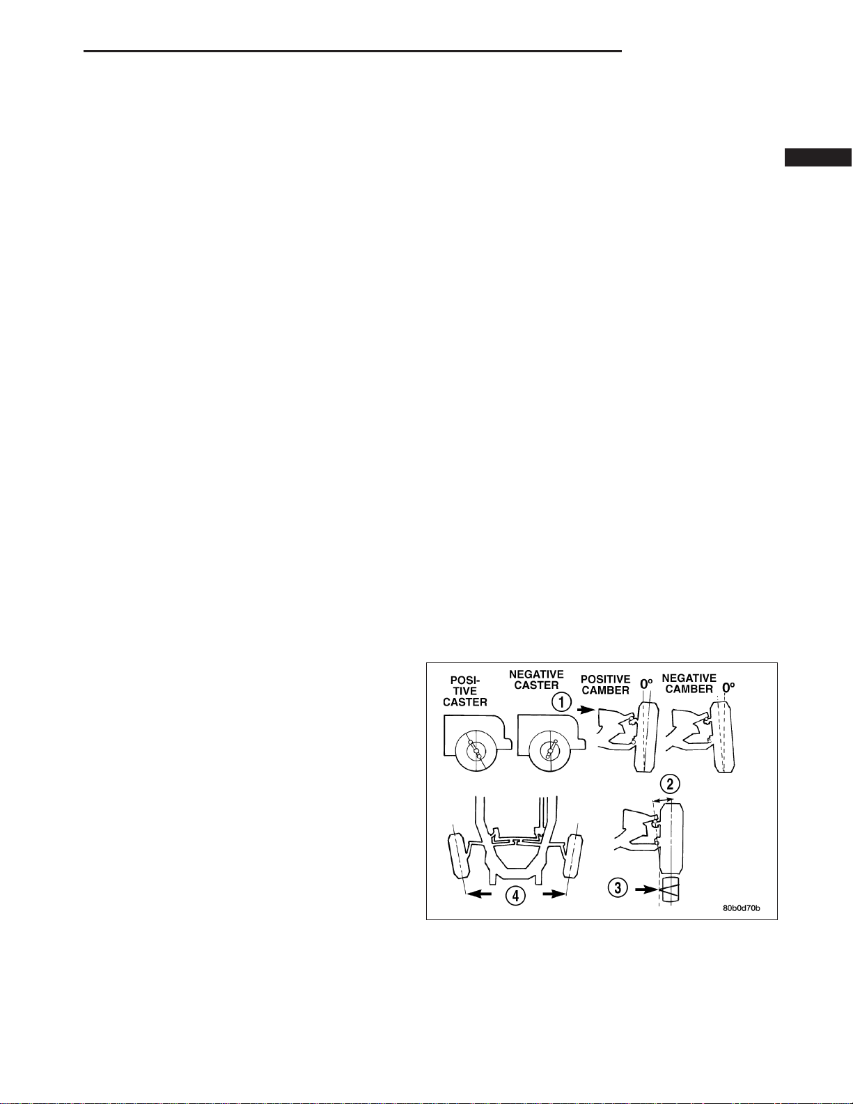
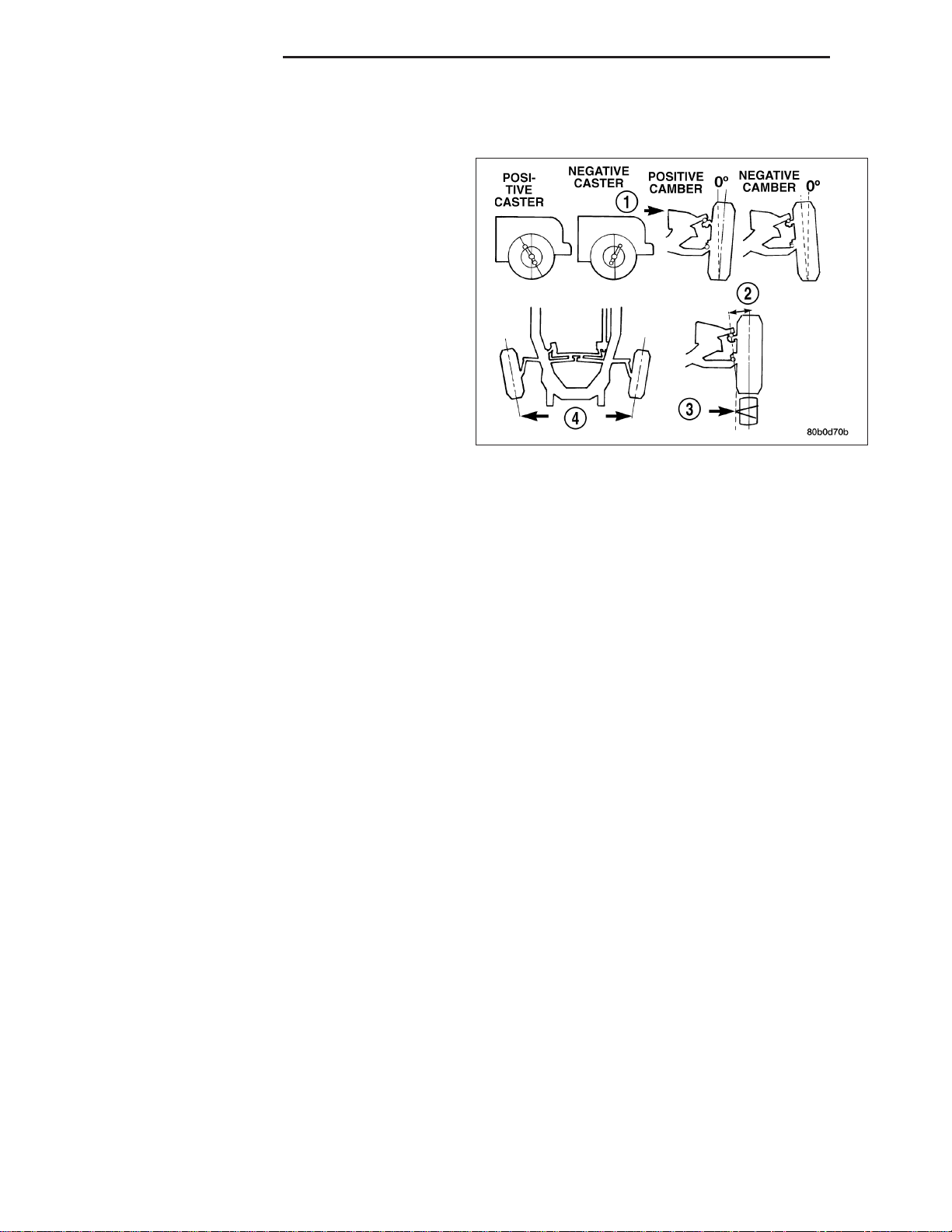
• CASTER (1) is the forward or rearward tilt of the
steering knuckle from vertical. Tilting the top of
the knuckle forward provides less positive caster.
Tilting the top of the knuckle rearward provides
more positive caster. Positive caster promotes
directional stability. This angle enables the front
wheels to return to a straight ahead position after
turns.
• CAMBER (2) is the inward or outward tilt of the
wheel relative to the center of the vehicle. Tilting
the top of the wheel inward provides negative
camber. Tilting the top of the wheel outward provides positive camber. Incorrect camber will
cause wear on the inside or outside edge of the
tire.
• TOE (4) is the difference between the leading
inside edges and trailing inside edges of the front tires. Wheel toe position out of specification cause’s unstable
steering, uneven tire wear and steering wheel off- center. The wheel toe position is the final front wheel alignment adjustment.
• THRUST ANGLE (3) is the angle of the rear axle relative to the centerline of the vehicle. Incorrect thrust angle
can cause off-center steering and excessive tire wear. Off-center steering, lead or pull and Minimal adjustment
(clearance between spring seat hole and leaf spring pin) can be made by loosening the U-Bolts and moving
one side forward and the other rearward. All damaged component(s) must be replaced to correct the thrust
angle.
DIAGNOSIS AND TESTING
PRE-ALIGNMENT INSPECTION
Before starting wheel alignment, the following inspection and necessary corrections must be completed. Refer to
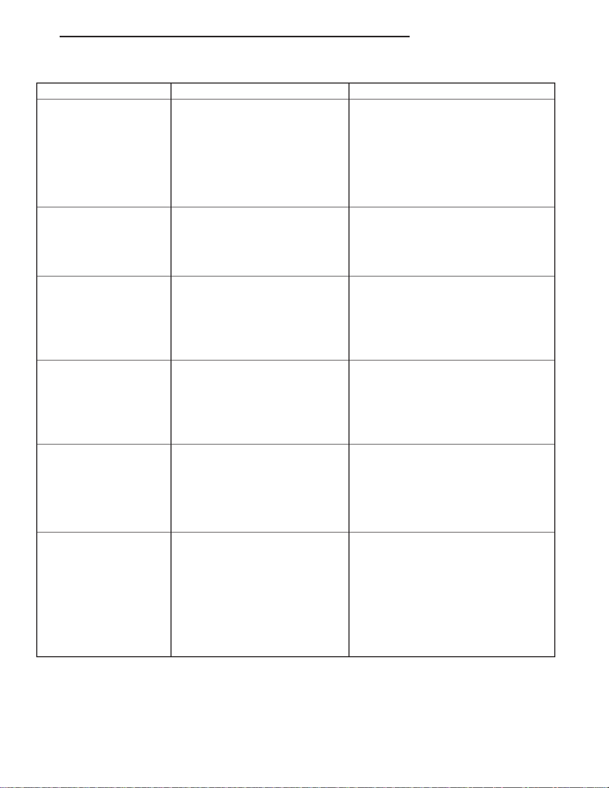
Suspension and Steering System Diagnosis Chart below for additional information.
1. Inspect tires for size, air pressure and tread wear.
2. Inspect front wheel bearings for wear.
3. Inspect front wheels for excessive radial or lateral runout and balance.
4. Inspect ball studs, linkage pivot points and steering gear for looseness, roughness or binding.
5. Check intermediate shaft for excessive loosness or binding.
6. Inspect suspension components for wear and noise.
7. Check suspension ride height, per the recommended proceedure for variation side to side, in front and rear.
8. Road test the vehicle.
Page 34
ND WHEEL ALIGNMENT 2 - 3
SUSPENSION AND STEERING SYSTEM DIAGNOSIS
CONDITION POSSIBLE CAUSES CORRECTION
FRONT END NOISE 1. Loose or worn wheel bearing. 1. Replace wheel bearing.
2. Loose or worn steering or
suspension components.
3. Loose body components. 3. Tighten or replace body components as
4. Loose or worn steering or
suspension components.
EXCESSIVE PLAY IN
STEERING
FRONT WHEELS SHIMMY 1. Loose or worn wheel bearing. 1. Replace wheel bearing.
VEHICLE INSTABILITY 1. Loose or worn wheel bearing. 1. Replace wheel bearing.
1. Loose or worn wheel bearing. 1. Replace wheel bearing.
2. Loose or worn steering or
suspension components.
3. Loose or worn steering gear. 3. Replace steering gear.
2. Loose or worn steering or
suspension components.
3. Tires worn or out of balance. 3. Replace or balance tires.
4. Alignment. 4. Align vehicle to specifications.
2. Loose or worn steering or
suspension components.
3. Tire pressure. 3. Adjust tire pressure.
4. Alignment. 4. Align vehicle to specifications.
2. Tighten or replace components as
necessary.
necessary
4. Tighten or replace components as
necessary.
2. Tighten or replace components as
necessary.
2. Tighten or replace components as
necessary.
2. Tighten or replace components as
necessary.
EXCESSIVE STEERING
EFFORT
VEHICLE PULLS TO ONE
SIDE
1. Loose or worn steering gear. 1. Replace steering gear.
2. Column coupler binding. 2. Replace coupler.
3. Steering Pump 3. Replace Pump
4. Tire pressure. 4. Adjust tire pressure.
5. Alignment. 5. Align vehicle to specifications.
1. Tire pressure. 1. Adjust tire pressure.
2. Tire. 2. Criss-Cross Front Tires.
3. Alignment. 3. Align vehicle to specifications.
4. Loose or worn steering or
suspension components.
5. Radial tire lead. 5. Rotate or replace tire as necessary.
6. Brake pull. 6. Repair brake as necessary.
7. Ride height. 7. Measure and adjust ride height.
4. Tighten or replace components as
necessary.
Page 35
2 - 4 WHEEL ALIGNMENT ND
STANDARD PROCEDURE
HEIGHT MEASUREMENT
The vehicle suspension height MUST be measured and adjusted before performing wheel alignment procedure.
Also when front suspension components have been replaced. This measure must be performed with the vehicle
supporting it’s own weight and taken on both sides of the vehicle.
FRONT RIDE HEIGHT MEASUREMENT
1. Inspect tires and set to correct pressure.
2. Jounce the front of the vehicle.
3. With vehicle on level ground or hoist, make the following measurements:
a. Front wheel spindle (center) to ground vertical distance.
b. Measure the center of front face of bolt on the rear leg of lower control arm and the center of front face of
front leg of control arm to ground vertical distance and take the average height.
c. Difference between spindle and control arm bolt to ground average distance should be 71mm+/- 6mm. Note
that the control arm bolt is lower than the spindle.
4. After making any ride height adjustment, roll vehicle preferably jouncing it also, to relieve camber Effects and
then re-measure Lower control arm bolt to ground height.
5. Repeat the previous steps until the ride height is within specifications.
REAR RIDE HEIGHT MEASUREMENT
1. Inspect tires and set to correct pressure.
2. Jounce the front of the vehicle.
3. With vehicle on level ground or hoist, make the following measurements:
a. Distance from the landing pad of the jounce bumper on the axle side to the jounce bumper cup lip of the
frame side.
b. The difference between the jounce bumper landing pad and the jounce bumper cup lip the reading should be
148 mm +/-10 mm for 9.259 axle, 154 mm +/-10 mm for 8.259 axle.
TOE ADJUSTMENT
SUSPENSION HEIGHT MESUREMENT MUST BE
PERFORMED BEFORE AN ALIGNMENT.
The wheel toe position adjustment is the final adjustment.
1. Start the engine and turn wheels both ways before
straightening the wheels. Secure the steering
wheel with the front wheels in the straight-ahead
position.
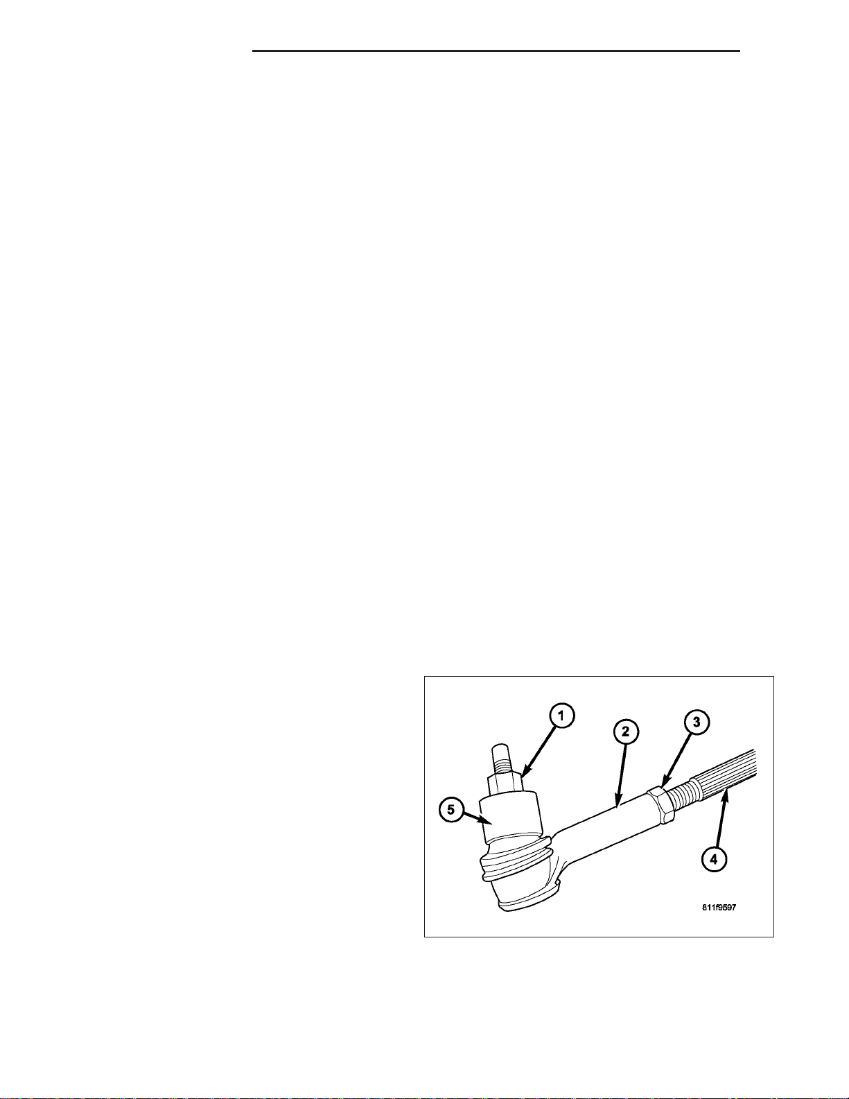
2. Loosen the tie rod jam nuts (3).
NOTE: Each front wheel should be adjusted for
one-half of the total toe position specification.
This will ensure the steering wheel will be centered when the wheels are positioned straightahead.
3. Adjust the wheel toe position by turning the inner tie rod (4) as necessary.
4. Tighten the tie rod jam nut (3) to 75 N·m (55 ft. lbs.).
5. Verify the specifications.
6. Turn off engine.
Page 36
ND WHEEL ALIGNMENT 2 - 5
CAMBER, CASTER AND TOE ADJUSTMENT
Camber and caster angle adjustments involve changing the position of the lower control arm with the slots in the
frame brackets to move the lower control arm inwards or outwards for proper adjustment. This can be achieved by
using a socket on the head of the cam bolt and turning clockwise or counterclockwise to achieve the
proper specification.
NOTE: Both front and rear lower control arm cam bolts are adjustable.
NOTE: Camber and caster adjustments must be made at the lower control arm The upper control arm is not
adjustable.
NOTE: When the lower control arm cam bolts are loosened the lower control arm will normally go outwards
automatically with the weight of the vehicle.
CASTER
Moving the rear position of the lower control arm at the frame in or out, will change the caster angle significantly
and camber angle only slightly. To maintain the camber angle while adjusting caster, move the rear of the lower
control arm in or out. Then move the front of the lower control arm slightly in the opposite direction.
CAMBER
Move both the front and rear of the lower control arm together in or out. This will change the camber angle significantly and caster angle slightly.
After adjustment is made tighten the lower control arm bolt & nuts to 203 N·m (150 ft. lbs.).
TOE ADJUSTMENT
The wheel toe position adjustment is the final adjustment.
1. Start the engine and turn wheels both ways before
straightening the wheels. Secure the steering
wheel with the front wheels in the straight-ahead
position.
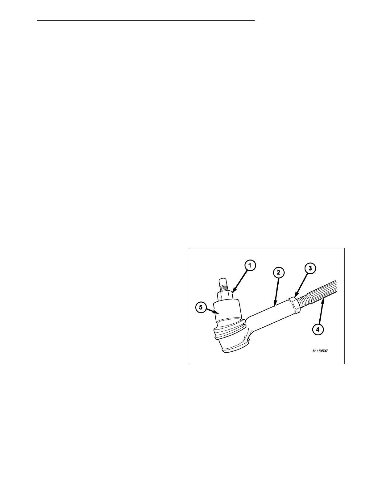
2. Loosen the tie rod jam nuts (3).
NOTE: Each front wheel should be adjusted for
one-half of the total toe position specification.
This will ensure the steering wheel will be centered when the wheels are positioned straightahead.
3. Adjust the wheel toe position by turning the inner
tie rod (4) as necessary.
4. Tighten the tie rod jam nut (3) to 75 N·m (55 ft. lbs.).
5. Verify the specifications.
6. Turn off engine.
Page 37
2 - 6 WHEEL ALIGNMENT ND
SPECIFICATIONS
ALIGNMENT
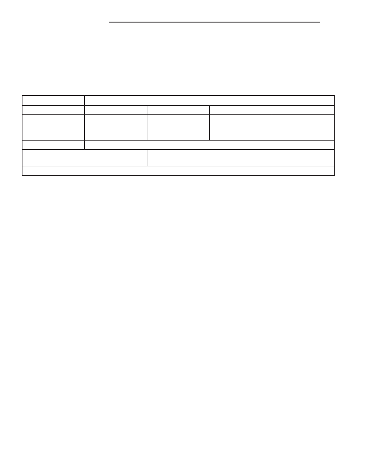
NOTE: All alignment specifications are in degrees.
SPECIFICATIONS
DESCRIPTION SPECIFICATION
VEHICLE WHEEL BASE CASTER CAMBER TOTAL TOE-IN
ALL 131 in 3.5 ± .05° .25° ± .50° .20° ± .05°
MAX RT/LT
DIFFERENCE
DESCRIPTION REAR SPECIFICATION
CAMBER
(-.10° ± 0.35°)
— -.20° ± .50° 0° ± .50° 0.05° ± 0.05°
TOTAL TOE-IN
(0.30° ± 0.35°)
THRUST ANGLE 0° ± 0.4°
Page 38

ND FRONT 2 - 7
FRONT
TABLE OF CONTENTS
page page
FRONT
DESCRIPTION
SUSPENSION .........................7
CONTROL ARMS .......................8
SPECIFICATIONS
TORQUE CHART .......................8
SPECIAL TOOLS
FRONT SUSPENSION ...................9
BUSHINGS
DESCRIPTION .........................11
REMOVAL
LOWER CONTROL ARM BUSHING ........11
UPPER CONTROL ARM BUSHING ........12
LOWER CONTROL ARM SHOCK BUSHING . 13
INSTALLATION
LOWER CONTROL ARM BUSHING ........13
UPPER CONTROL ARM BUSHING ........14
LOWER CONTROL ARM SHOCK BUSHING . 15
HUB / BEARING
REMOVAL .............................15
INSTALLATION .........................16
KNUCKLE
DESCRIPTION .........................16
OPERATION ...........................17
REMOVAL .............................17
INSTALLATION .........................19
LOWER BALL JOINT
DIAGNOSIS AND TESTING
LOWER BALL JOINT ...................21
REMOVAL .............................21
INSTALLATION .........................24
LOWER CONTROL ARM
REMOVAL .............................25
INSTALLATION .........................28
SHOCK
DIAGNOSIS AND TESTING
SHOCK .............................30
REMOVAL .............................31
INSTALLATION .........................32
SPRING
REMOVAL .............................33
INSTALLATION .........................33
STABILIZER BAR
DESCRIPTION .........................34
OPERATION ...........................34
REMOVAL .............................35
INSTALLATION .........................35
STABILIZER LINK
REMOVAL .............................36
INSTALLATION .........................36
UPPER BALL JOINT
DIAGNOSIS AND TESTING
UPPER BALL JOINT ...................37
UPPER CONTROL ARM
REMOVAL .............................37
INSTALLATION .........................38
FRONT
DESCRIPTION
SUSPENSION
The front suspension is designed to allow each wheel to adapt to different road surfaces independently. The wheels
are mounted to hub/bearings units bolted to the steering knuckle. The double-row hub bearings are sealed and
lubricated for life. The steering knuckles turn (pivot) on ball joints.
The front suspension is comprised of :
• Shock absorbers
• Control arms
• Steering knuckles
• Stabilizer bar
• Stabilizer link
• Tie Rod Ends
• Hub/Bearing
• Rack & Pinion
• Ball Joints
Page 39
2 - 8 FRONT ND
NOTE: Components attached with a nut must be torqued to specification.
NOTE: Suspension components with rubber/urethane bushings should be tightened with the vehicle at normal ride height. It is important to have the springs supporting the weight of the vehicle when the fasteners
are torqued. If springs are not at their normal ride position, vehicle ride comfort could be affected and premature bushing wear may occur.
CONTROL ARMS
The lower control arms bolt to the lower frame brackets and pivots through bushings. The frame brackets have
slotted holes which allow the arms to be adjusted for caster and camber.
The control arms have lube for life ball studs. The control arm travel (jounce) is limited through the use of rubber/
urethane bumpers. Rebound travel is limited by the shock absorber.
SPECIFICATIONS
TORQUE CHART
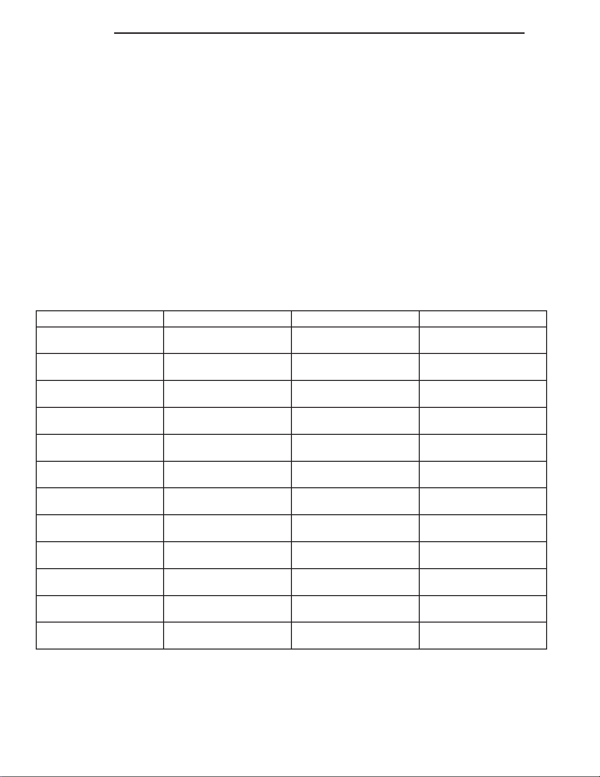
TORQUE SPECIFICATIONS
DESCRIPTION N·m Ft. Lbs. In. Lbs.
Shock Absorber
Upper Nut
Shock Absorber
Lower Bolt
Lower Suspension Arm
Frame Nuts
Lower Suspension Arm
Ball Joint Nut
Upper Suspension Arm
Frame Nuts
Upper Suspension Arm
Ball Joint Nut
Stabilizer Bar
Frame Bolt
Stabilizer Link
to Lower Control Arm
Stabilizer Link
Stabilizer Bar Nut
Hub/Bearing
Bolts
Tie Rod End to Knuckle
Nut
Tie Rod End
Jam Nut
102 75 —
81 60 —
244 180 —
75 55 —
102 75 —
75 55 —
61 45 —
169 125 —
37 27 —
163 120 —
75 55 —
75 55 —
Page 40
ND FRONT 2 - 9
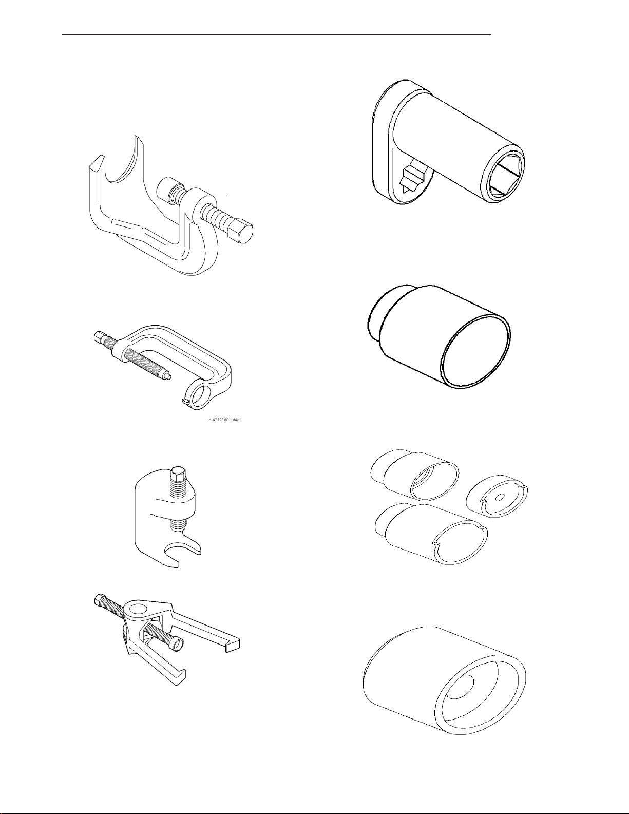
SPECIAL TOOLS
FRONT SUSPENSION
Wrench, Shock Nut 9362
PULLER - 8677
BALL JOINT PRESS - C-4212F
BALL JOINT - 9604
BALL JOINT - 9654
BALL JOINT - 8441-4
Page 41
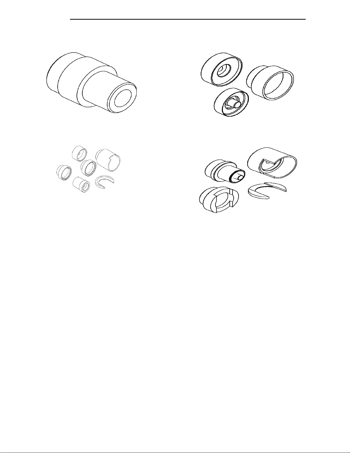
2 - 10 FRONT ND
BALL JOINT - 8445-3
BUSHING - 9334
BUSHING - 9603
BUSHINGS - 9601
Page 42
ND FRONT 2 - 11
BUSHINGS
DESCRIPTION
Suspension components with rubber/urethane bushings should be tightened with the vehicle at normal ride height.
It is important to have the springs supporting the weight of the vehicle when the fasteners are torqued. If springs are
not at their normal ride position, vehicle ride comfort could be affected and premature bushing wear may occur.
REMOVAL
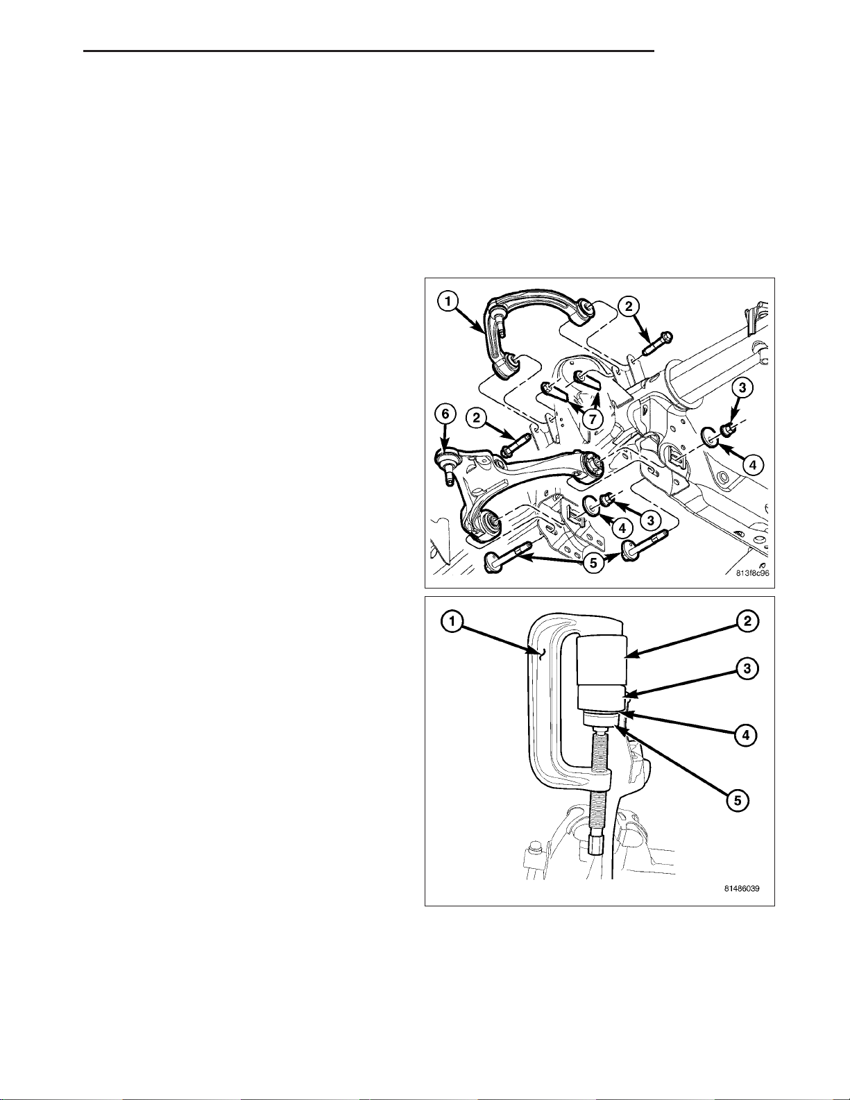
LOWER CONTROL ARM BUSHING
1. Remove the lower control arm (6) (Refer to 2 SUSPENSION/FRONT/LOWER CONTROL ARM REMOVAL).
2. Secure the control arm in a vise.
NOTE: Extreme pressure lubrication must be used
on the threaded portions of the tool. This will
increase the longevity of the tool and insure
proper operation during the removal and installation process.
3. Install special tools C-4212-F (press) (1), 9334–5
(Receiver) (2), 9603–3 (Driver) (5) to press the
bushing out of the lower control arm.
Page 43
2 - 12 FRONT ND
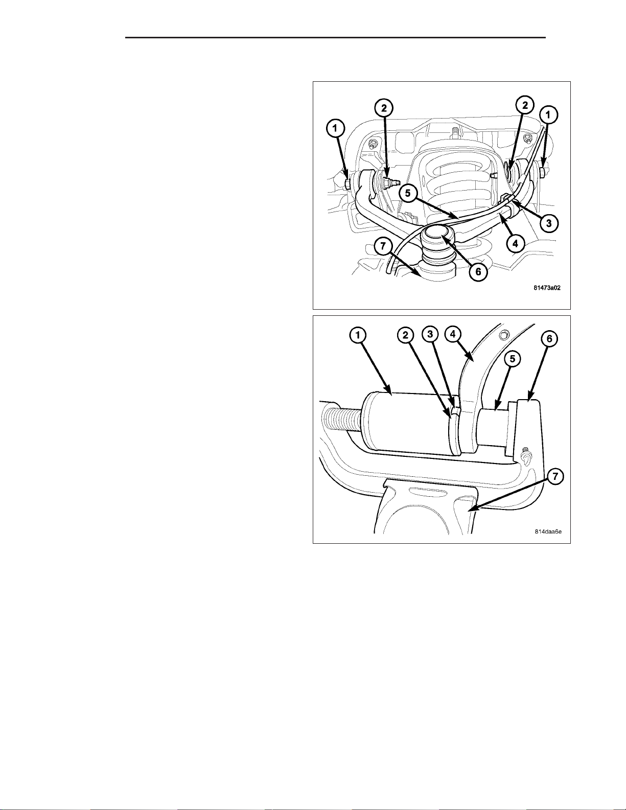
UPPER CONTROL ARM BUSHING
1. Remove the upper control arm (4) (Refer to 2 SUSPENSION/FRONT/UPPER CONTROL ARM REMOVAL).
2. Secure the control arm in a vise (7).
NOTE: Extreme pressure lubrication must be used
on the threaded portions of the tool. This will
increase the longevity of the tool and insure
proper operation during the removal and installation process.
3. Install special tools C-4212-F (press) (6),
6761(Receiver) (1), 9601-2 (Reaction Plate) (2),
9601-1 (Driver) (5) to press the bushing (3) out of
the upper control arm (4).
Page 44
ND FRONT 2 - 13
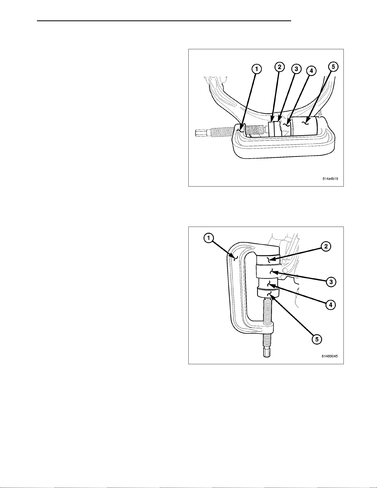
LOWER CONTROL ARM SHOCK BUSHING
1. Remove the shock (Refer to 2 - SUSPENSION/
FRONT/SHOCK - REMOVAL).
NOTE: Extreme pressure lubrication must be used
on the threaded portions of the tool. This will
increase the longevity of the tool and insure
proper operation during the removal and installation process.
2. Install special tools to press the bushing (3) out of
the lower control arm (4) using special tools
C-4212-F (Press) (1), 9653–1 (driver) (4) and 9602
(Receiver) (5).
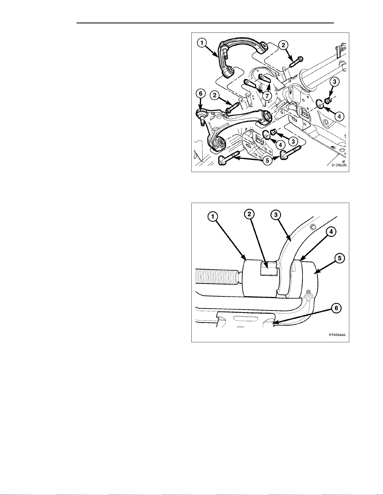
INSTALLATION
LOWER CONTROL ARM BUSHING
1. Install the new bushing (4) into the lower control
arm (3) using tools C-4212-F (Press) (1), 9603–2
(Depth Gauge) (2), 9603–1 (Driver) (5).
Page 45
2 - 14 FRONT ND
2. Remove the control arm from the vise.
3. Install the lower control arm (6) (Refer to 2 - SUSPENSION/FRONT/LOWER CONTROL ARM INSTALLATION).
4. Reset the vehicle ride height (Refer to 2 - SUSPENSION/WHEEL ALIGNMENT - STANDARD
PROCEDURE).
5. Perform a wheel alignment (Refer to 2 - SUSPENSION/WHEEL ALIGNMENT - STANDARD
PROCEDURE).
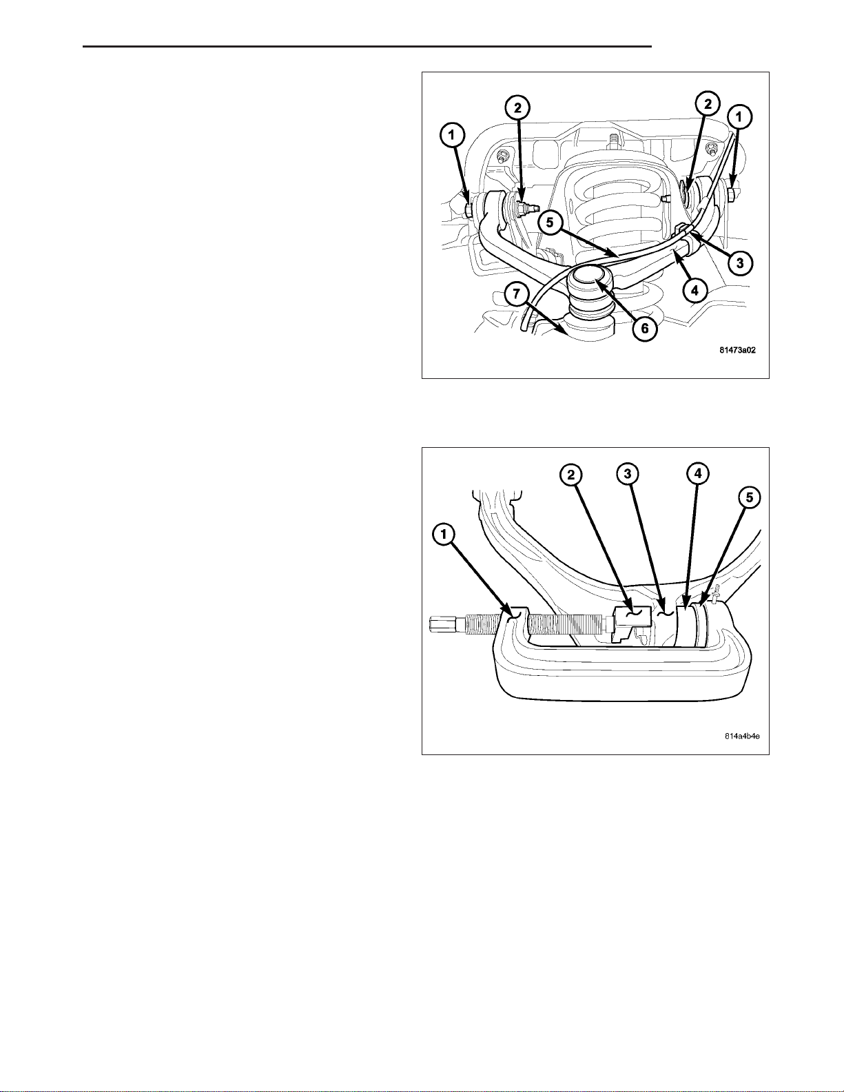
UPPER CONTROL ARM BUSHING
1. Install the new bushing (2) into the lower control (3)
arm using tools C-4212-F (Press) (5), 9601-3
(Depth Gauge) (4), 9601-4 (Driver) (1).
2. Remove the control arm from the vise (6).
Page 46
ND FRONT 2 - 15
3. Install the upper control arm (4) (Refer to 2 - SUSPENSION/FRONT/UPPER CONTROL ARM INSTALLATION).
4. Reset the vehicle ride height (Refer to 2 - SUSPENSION/WHEEL ALIGNMENT - STANDARD
PROCEDURE).
5. Perform a wheel alignment (Refer to 2 - SUSPENSION/WHEEL ALIGNMENT - STANDARD
PROCEDURE).
LOWER CONTROL ARM SHOCK BUSHING
NOTE: Extreme pressure lubrication must be used
on the threaded portions of the tool. This will
increase the longevity of the tool and insure
proper operation during the removal and installation process.
1. Install the new shock bushing (3) into the lower
control arm (3) using tools C-4212-F (Press) (1),
9653–3 (driver) (5), 9602–2 (Depth gauge) (2) the
depth gauge will automatically set the depth of the
bushing (4) in the control arm (3).
2. Install the shock (Refer to 2 - SUSPENSION/
FRONT/SHOCK - INSTALLATION).
HUB / BEARING
REMOVAL
1. Raise and support the vehicle.
2. Remove the wheel and tire assembly.
3. Remove the brake caliper and rotor (Refer to 5 - BRAKES/HYDRAULIC/MECHANICAL/ROTORS - REMOVAL).
4. Remove the ABS wheel speed sensor if equipped, (Refer to 5 - BRAKES/ELECTRICAL/FRONT WHEEL SPEED
SENSOR - REMOVAL).
5. Remove the halfshaft nut 4X4 only.
Page 47
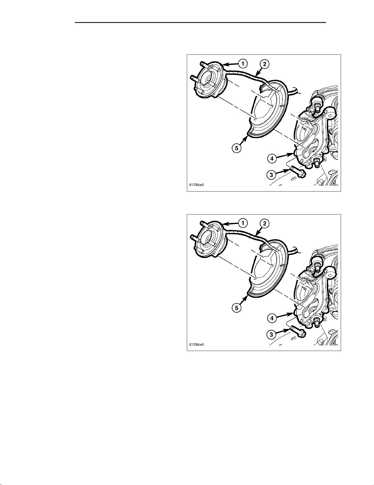
2 - 16 FRONT ND
NOTE: Do not strike the knuckle with a hammer to remove the tie rod end or the ball joint. Damage to the
steering knuckle will occur.
6. Pull down on the steering knuckle to separate the
halfshaft from the hub/bearing. 4X4 only
7. Remove the three hub/bearing mounting bolts (3)
from the steering knuckle (4).
8. Slide the hub/bearing (1) out of the steering
knuckle (4).
9. Remove the brake dust shield (5).
INSTALLATION
1. Install the brake dust shield (5).
2. Install the hub/bearing (1) into the steering knuckle
(4) and tighten the bolts (3) to 163 N·m (120 ft.
lbs.).
3. Install the brake rotor and caliper (Refer to 5 BRAKES/HYDRAULIC/MECHANICAL/ROTORS INSTALLATION).
4. Install the ABS wheel speed sensor (4) if equipped
(Refer to 5 - BRAKES/ELECTRICAL/FRONT
WHEEL SPEED SENSOR - INSTALLATION).
5. Install the halfshaft nut and tighten to 251 N·m (185 ft. lbs.) 4X4 only.
6. Install the wheel and tire assembly (Refer to 22 - TIRES/WHEELS/WHEELS - STANDARD PROCEDURE).
7. Remove the support and lower vehicle.
KNUCKLE
DESCRIPTION
The knuckle is a single casting with legs machined for the upper and lower ball joints. The knuckle also has
machined mounting locations for the front brake calipers and hub bearing.
Page 48
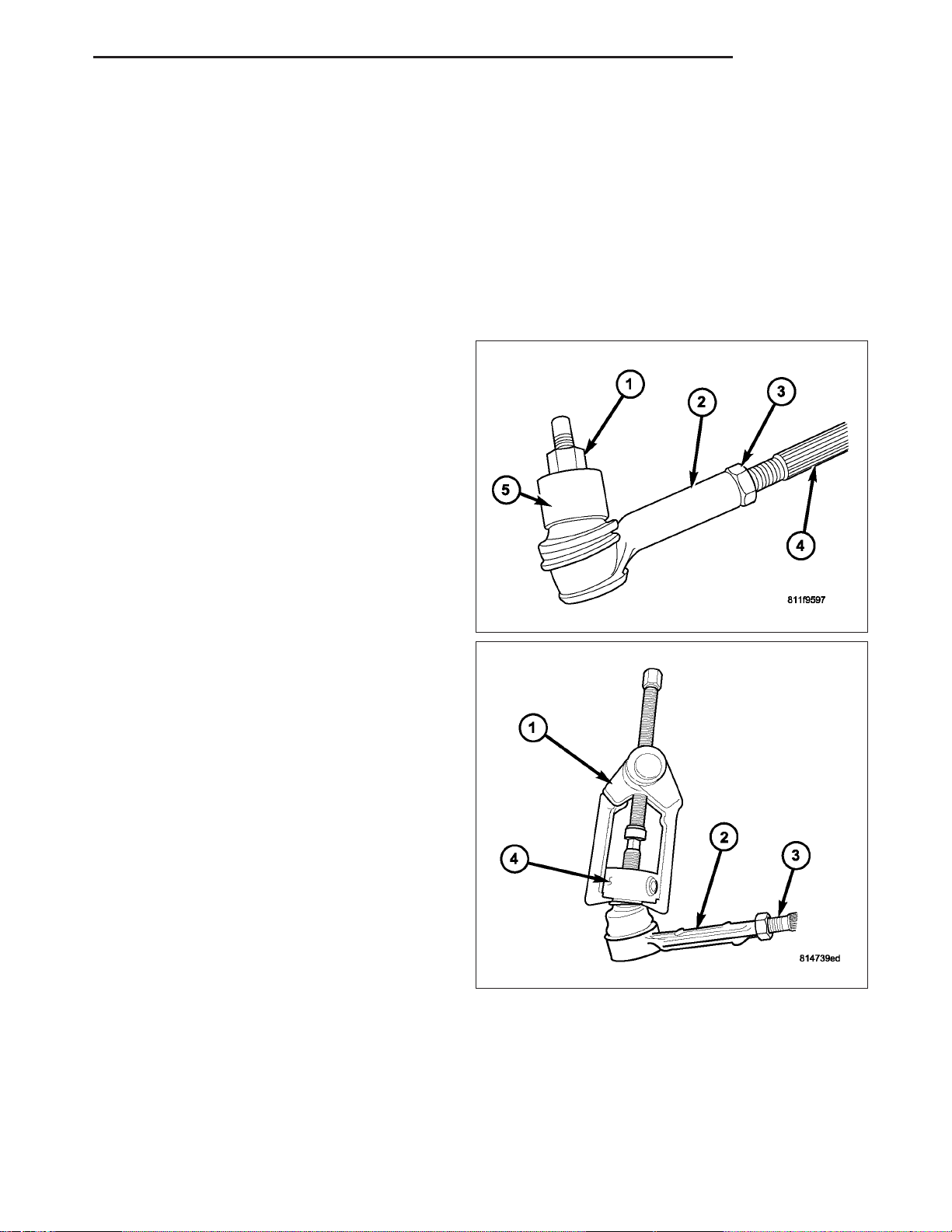
ND FRONT 2 - 17
OPERATION
The steering knuckle pivot between the upper and lower ball joint. Steering linkage attached to the knuckle allows
the vehicle to be steered.
REMOVAL
1. Raise and support the vehicle.
2. Remove the wheel and tire assembly.
3. Remove the brake caliper, rotor (Refer to 5 - BRAKES/HYDRAULIC/MECHANICAL/ROTORS - REMOVAL),
shield and ABS wheel speed sensor if equipped (Refer to 5 - BRAKES/ELECTRICAL/FRONT WHEEL SPEED
SENSOR - REMOVAL).
4. Remove the front halfshaft nut 4X4 only.
5. Remove the tie rod end nut (1).
6. Separate the tie rod (2) from the knuckle with
Remover C-3894–A (1).
CAUTION: When installing Remover 8677 to separate the ball joint, be careful not to damage the
ball joint seal.
Page 49
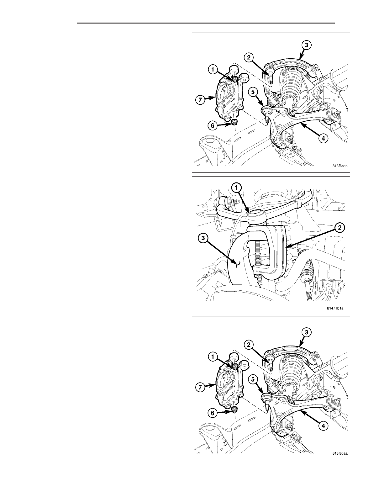
2 - 18 FRONT ND
7. Remove the upper ball joint nut (1).
8. Separate the ball joint (1) from the knuckle (3) with
Remover 8677 (2).
9. Install an hydraulic jack to support the lower control
arm.
10. Remove the lower ball joint nut (6).
Page 50
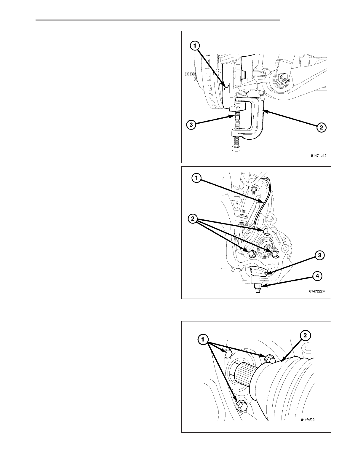
ND FRONT 2 - 19
11. Separate the ball joint (3) from the knuckle (1)
with Remover 8677 (2) and remove the knuckle
(1).
12. Remove the hub/bearing bolts (2) from the
knuckle (1).
13. Remove the hub/bearing from the steering
knuckle (1) (Refer to 2 - SUSPENSION/FRONT/
HUB / BEARING - REMOVAL).
14. Remove the steering knuckle (1).
INSTALLATION
CAUTION: The ball joint stud tapers must be
CLEAN and DRY before installing the knuckle.
Clean the stud tapers with mineral spirits to
remove dirt and grease.
1. Install the hub/bearing to the steering knuckle and
tighten the bolts (1) to 163 N·m (120 ft. lbs.).
Page 51
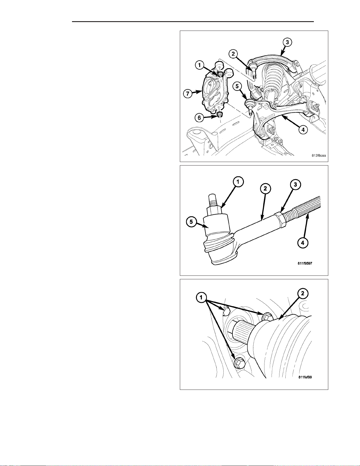
2 - 20 FRONT ND
2. Install the knuckle (7) onto the upper (2) and lower
ball joints (5).
3. Install the upper (1) and lower ball joint nuts (6).
Tighten the nut to 75 N·m (55 ft. lbs.).
4. Remove the hydraulic jack from the lower control
arm (4).
5. Install the tie rod end (2) and tighten the nut (1) to
75 N·m (55 ft. lbs.).
6. Install the front halfshaft (2) into the hub/bearing
4X4 only.
7. Install the the halfshaft nut and tighten to 251 N·m
(185 ft. lbs.) 4X4 only.
8. Install the ABS wheel speed sensor if equipped
(Refer to 5 - BRAKES/ELECTRICAL/FRONT
WHEEL SPEED SENSOR - INSTALLATION) and
brake shield, rotor and caliper (Refer to 5 BRAKES/HYDRAULIC/MECHANICAL/ROTORS INSTALLATION).
9. Install the wheel and tire assembly (Refer to 22 TIRES/WHEELS/WHEELS - STANDARD PROCEDURE).
10. Remove the support and lower the vehicle.
11. Perform a wheel alignment (Refer to 2 - SUSPENSION/WHEEL ALIGNMENT - STANDARD PROCEDURE).
Page 52
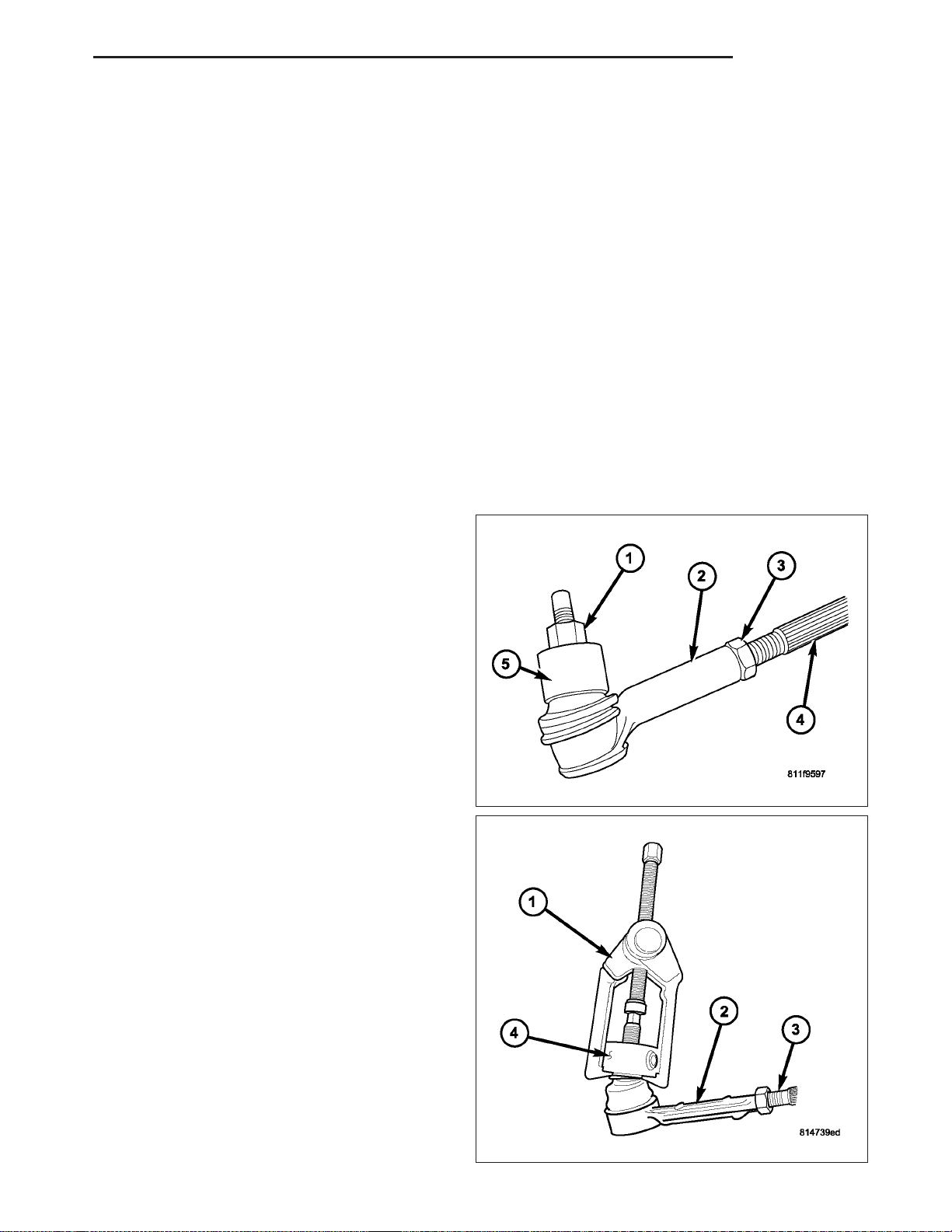
ND FRONT 2 - 21
LOWER BALL JOINT
DIAGNOSIS AND TESTING
LOWER BALL JOINT
NOTE: If the ball joint is equipped with a lubrication fitting, grease the joint then road test the vehicle before
performing test.
1. Raise the front of the vehicle. Place safety floor stands under both lower control arms as far outboard as possible. Lower the vehicle to allow the stands to support some or all of the vehicle weight.
2. Mount a dial indicator solidly to the topside of the lower control arm and then zero the dial indicator.
3. Position the indicator plunger against the bottom surface of the steering knuckle.
NOTE: The dial indicator plunger must be perpendicular to the machined surface of the steering knuckle.
4. Position a pry bar under the tire assembly. Pry upwards on the tire assembly.
5. If the travel exceeds 0.5 mm (0.020 in.), replace the lower ball joint (Refer to 2 - SUSPENSION/FRONT/LOWER
BALL JOINT - REMOVAL).
REMOVAL
1. Remove the tire and wheel assembly.
2. Remove the brake caliper and rotor (Refer to 5 BRAKES/HYDRAULIC/MECHANICAL/ROTORS REMOVAL).
3. Remove the outer tie rod retaining nut (1) from the
knuckle (5).
4. Separate the tie rod (1) from the steering knuckle
using special tool C-3894–A (1) (Refer to 19 STEERING/LINKAGE/TIE ROD END - REMOVAL).
Page 53
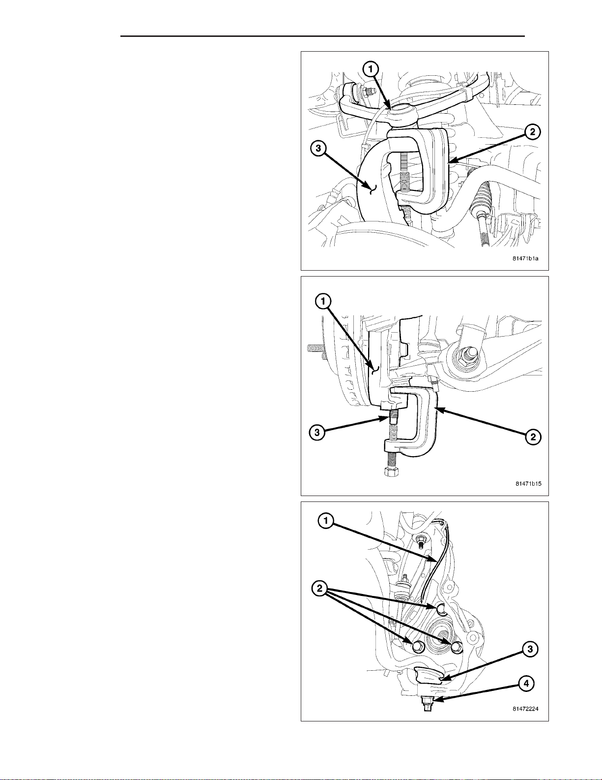
2 - 22 FRONT ND
5. Remove the upper ball joint nut, then separate the
upper ball joint (1) from the knuckle (3) using special tool 8677 (2).
6. Remove the lower ball joint nut, then separate the
lower ball joint (3) from the steering knuckle (1)
using special tool 8677 (2).
7. Remove the steering knuckle (1) (Refer to 2 - SUSPENSION/FRONT/KNUCKLE - REMOVAL).
Page 54
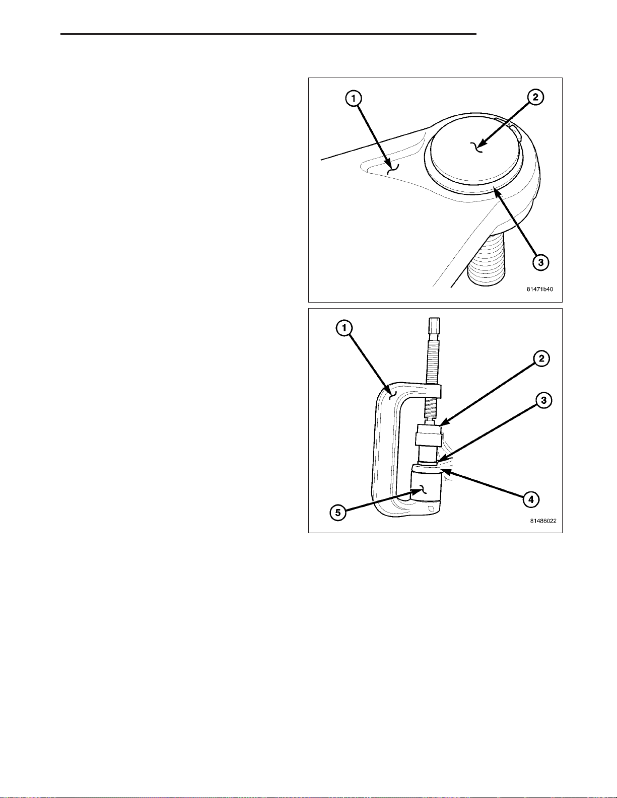
ND FRONT 2 - 23
8. Move the halfshaft to the side and support the halfshaft out of the way 4X4 only.
9. Remove the snap ring (3) from the ball joint flange
(2).
NOTE: Extreme pressure lubrication must be used
on the threaded portions of the tool. This will
increase the longevity of the tool and insure
proper operation during the removal and installation process.
10. Press the ball joint (3) from the lower control arm
(4) using special tools C-4212-F (PRESS) (1),
8445–3 (Driver) (2) and 9604 (Receiver) (5).
Page 55
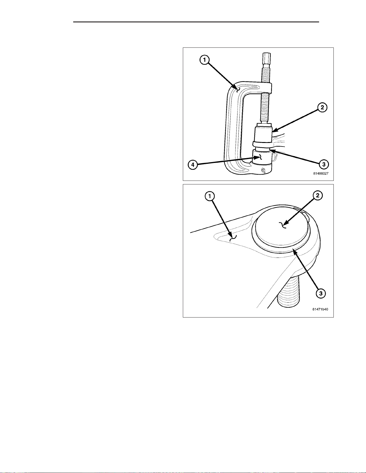
2 - 24 FRONT ND
INSTALLATION
NOTE: Extreme pressure lubrication must be used
on the threaded portions of the tool. This will
increase the longevity of the tool and insure
proper operation during the removal and installation process.
1. Install the ball joint (3) into the control arm and
press in using special tools C-4212-F (press) (1),
8441–4 (Receiver) (2) and 9654–1 (Driver) (4).
2. Install the snap ring (3) around the ball joint flange
(2).
3. Remove the support for the halfshaft and install into position 4X4 only.
4. Install the steering knuckle (Refer to 2 - SUSPENSION/FRONT/KNUCKLE - INSTALLATION).
Page 56
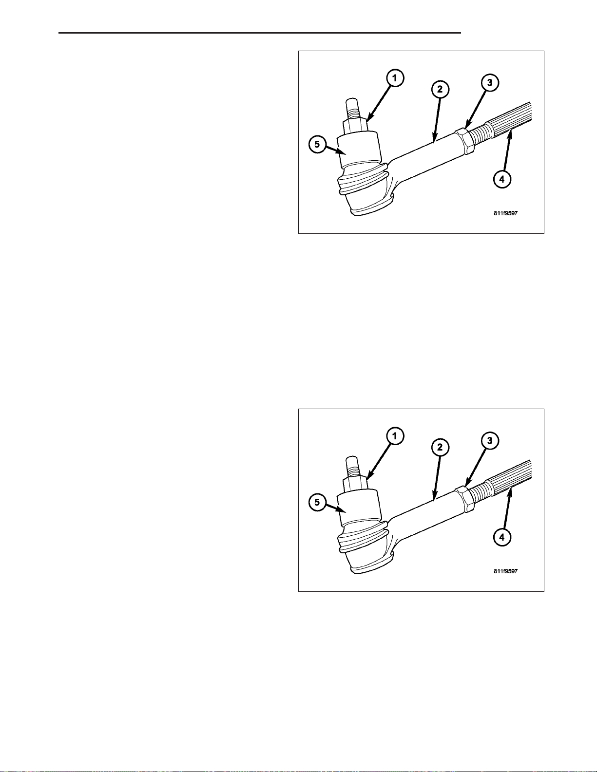
ND FRONT 2 - 25
5. Install the tie rod end (2) into the steering knuckle
(5), then install the retaining nut (1) and tighten to
75 N·m (55 ft. lbs.) (Refer to 19 - STEERING/LINKAGE/TIE ROD END - INSTALLATION).
6. Install and tighten the halfshaft nut to 251 N·m (185
ft. lbs.). (If Equipped).
7. Install the brake caliper and rotor (Refer to 5 BRAKES/HYDRAULIC/MECHANICAL/ROTORS INSTALLATION).
8. Install the tire and wheel assembly (Refer to 22 TIRES/WHEELS/WHEELS - STANDARD PROCEDURE).
9. Check the vehicle ride height (Refer to 2 - SUSPENSION/WHEEL ALIGNMENT - STANDARD
PROCEDURE).
10. Perform a wheel alignment (Refer to 2 - SUSPENSION/WHEEL ALIGNMENT - STANDARD PROCEDURE).
LOWER CONTROL ARM
REMOVAL
1. Raise and support the vehicle.
2. Remove the wheel and tire assembly.
3. Remove the disc brake caliper assembly (Refer to 5 - BRAKES/HYDRAULIC/MECHANICAL/DISC BRAKE CALIPERS - REMOVAL).
4. Remove the disc brake rotor (Refer to 5 - BRAKES/HYDRAULIC/MECHANICAL/ROTORS - REMOVAL).
5. Disconnect the wheel speed sensor at the wheel well.
6. Remove tie rod end jam nut (1).
Page 57
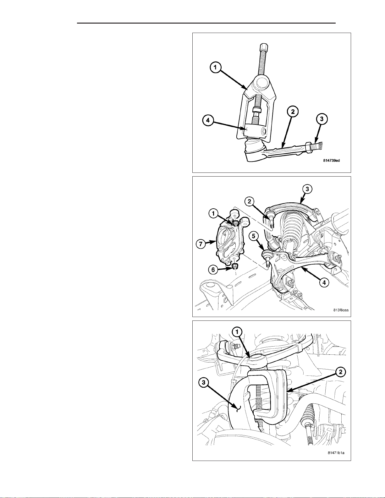
2 - 26 FRONT ND
7. Disconnect the tie rod (2) from the knuckle using
special tool C-3894–A (1) (Refer to 19 - STEERING/LINKAGE/TIE ROD END - REMOVAL).
8. Remove the front halfshaft nut 4X4.
9. Remove the upper ball joint nut. Separate the
upper ball joint (1) from the steering knuckle (3)
with Remover 8677 (2).
Page 58
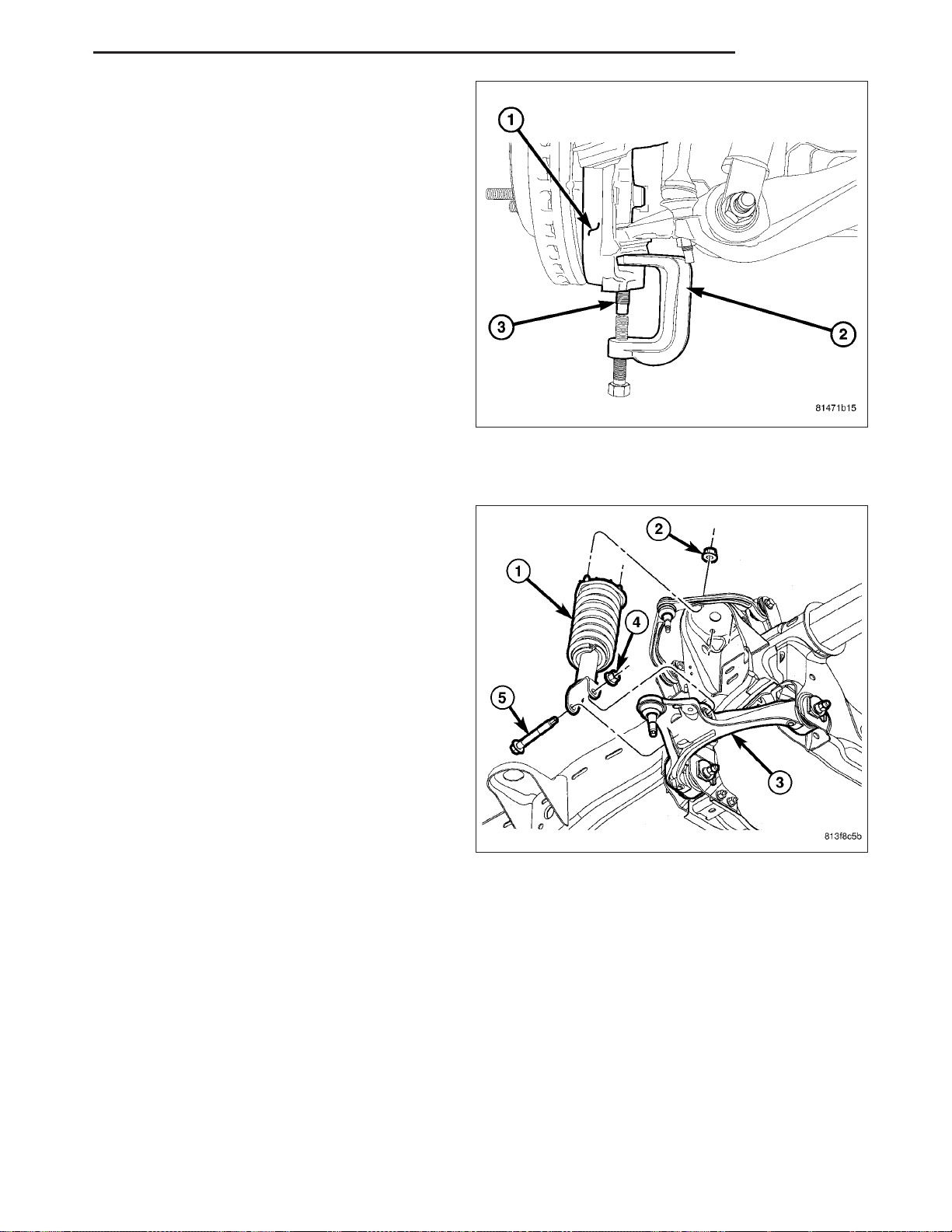
ND FRONT 2 - 27
10. Remove the lower ball joint nut (3). Separate the
lower ball joint (3) from the steering knuckle (1)
with Remover 8677 (2).
11. Remove the steering knuckle (7) (Refer to 2 - SUSPENSION/FRONT/KNUCKLE - REMOVAL).
12. Remove the stabilizer bar link (Refer to 2 - SUS-
PENSION/FRONT/STABILIZER LINK REMOVAL).
13. Remove the shock absorber lower bolt (4) and nut
(5).
Page 59
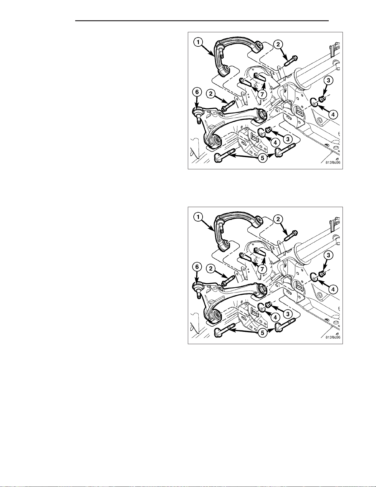
2 - 28 FRONT ND
14. Remove the lower control arm bolts (3) ,nuts (5)
and washers(4).
15. Remove the lower control arm (6) from the
vehicle.
INSTALLATION
NOTE: All suspension components should be tighten with the weight of the vehicle on them (curb height).
1. Position the lower control arm (6) at the frame rail
brackets. Install the pivot bolts (3) washers (4) and
nuts (5). Tighten the nuts finger-tight.
CAUTION: The ball joint stud taper must be
CLEAN and DRY before installing the knuckle.
Clean the stud taper with mineral spirits to remove
dirt and grease.
Page 60
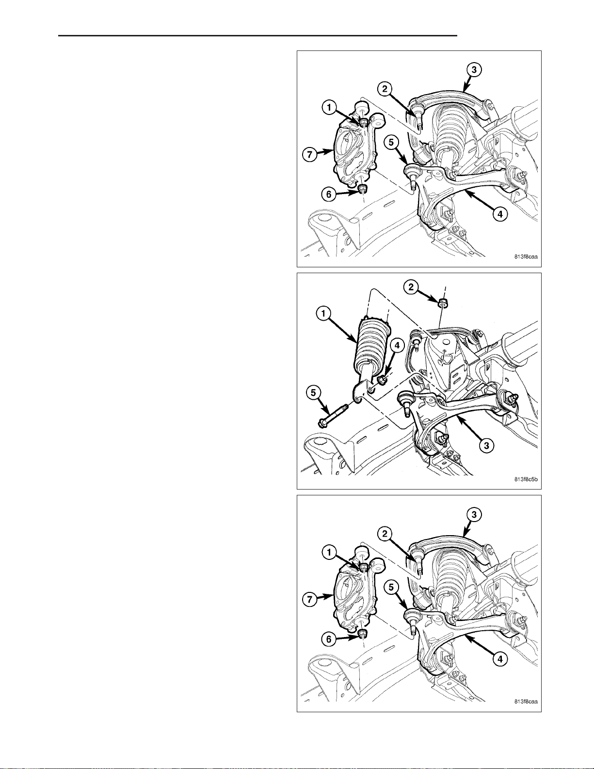
ND FRONT 2 - 29
2. Install the steering knuckle (7) (Refer to 2 - SUSPENSION/FRONT/KNUCKLE - INSTALLATION).
3. Insert the lower ball joint (6) into the steering
knuckle (7). Install and tighten the retaining nut (6)
to 81 N·m (60 ft. lbs.).
4. Install shock absorber lower bolt (4) and nut (5).
Tighten to 81 N·m (60 ft. lbs.).
5. Install the front halfshaft nut 4X4.
6. Insert the upper ball joint (2) into the steering
knuckle (7). Install and tighten the retaining nut (1)
to 75 N·m (55 ft. lbs.).
Page 61
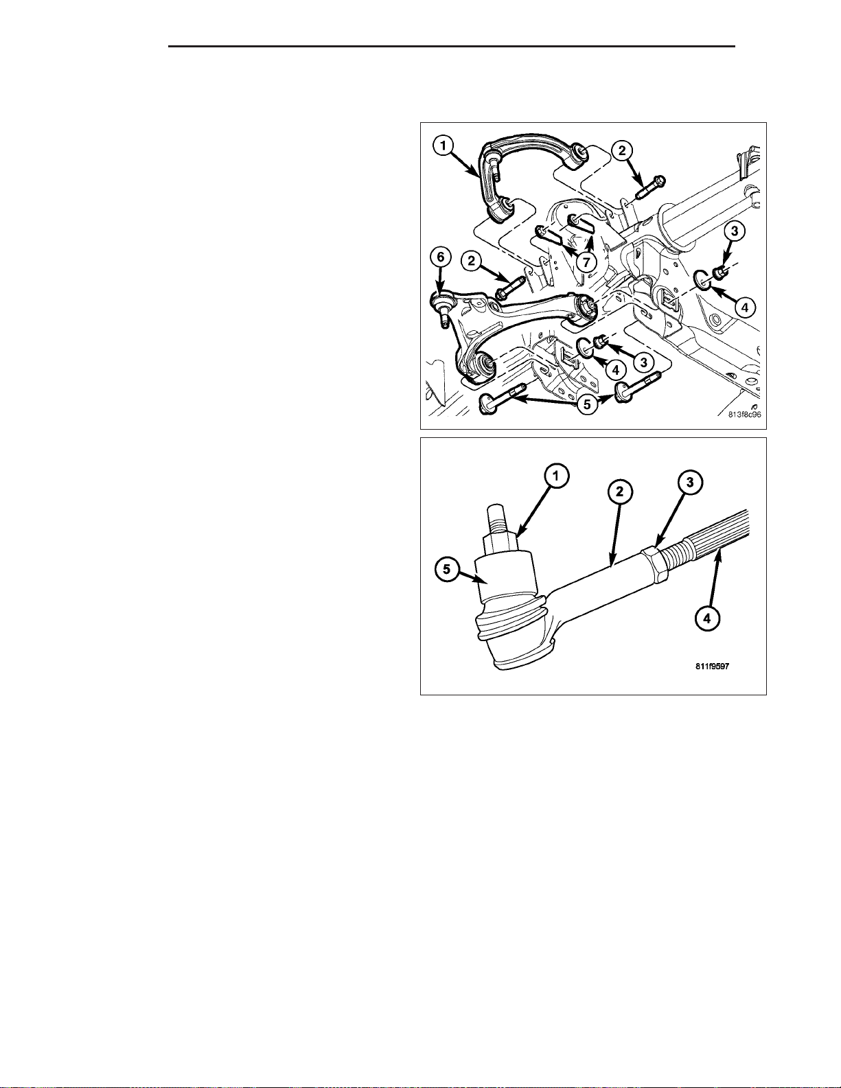
2 - 30 FRONT ND
7. Install the stabilizer bar link (Refer to 2 - SUSPENSION/FRONT/STABILIZER LINK - INSTALLATION) and tighten
to 169 N·m (125 ft. lbs.).
8. Tighten the lower control arm pivot nut (5) and
bolts (3) (to 244 N·m (180 ft. lbs.).
9. Insert the outer tie rod end (2) into the steering
knuckle (5). Install and tighten the retaining nut (1)
to 75 N·m (55 ft. lbs.).
10. Install the disc brake rotor (Refer to 5 - BRAKES/HYDRAULIC/MECHANICAL/ROTORS - INSTALLATION).
11. Install the disc brake caliper and adaptor assembly (2) and tighten to 135 N·m (100 ft. lbs.) (Refer to 5 -
BRAKES/HYDRAULIC/MECHANICAL/DISC BRAKE CALIPERS - INSTALLATION).
12. Install the wheel and tire assembly, (Refer to 22 - TIRES/WHEELS/WHEELS - STANDARD PROCEDURE).
13. Remove the support and lower the vehicle.
14. Perform a wheel alignment (Refer to 2 - SUSPENSION/WHEEL ALIGNMENT - STANDARD PROCEDURE).
SHOCK
DIAGNOSIS AND TESTING
SHOCK
A knocking or rattling noise from a shock absorber may be caused by movement between mounting bushings and
metal brackets or attaching components. These noises can usually be stopped by tightening the attaching nuts. If
the noise persists, inspect for damaged and worn bushings, and attaching components. Repair as necessary if any
of these conditions exist.
Page 62
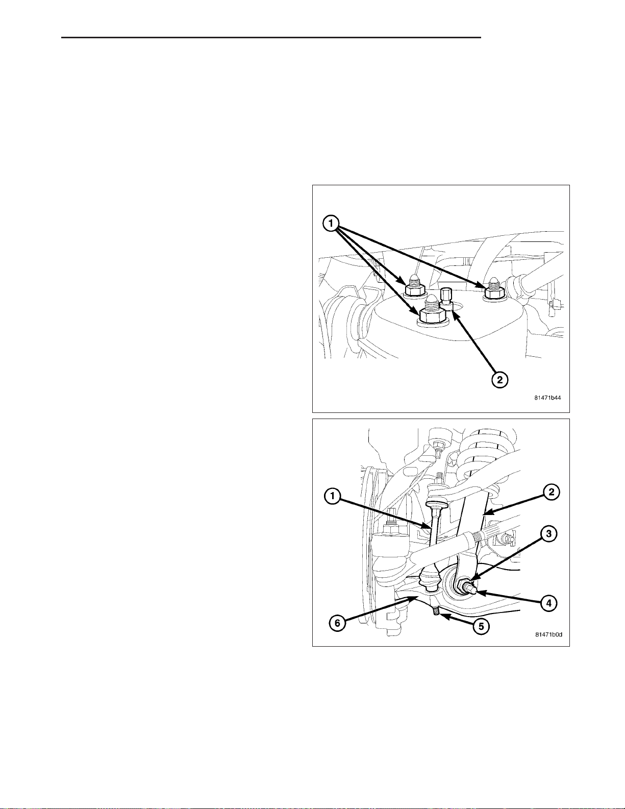
ND FRONT 2 - 31
A squeaking noise from the shock absorber may be caused by the hydraulic valving and may be intermittent. This
condition is not repairable and the shock absorber must be replaced.
The shock absorbers are not refillable or adjustable. If a malfunction occurs, the shock absorber must be replaced.
To test a shock absorber, hold it in an upright position and force the piston in and out of the cylinder four or five
times. The action throughout each stroke should be smooth and even.
The shock absorber bushings do not require any type of lubrication. Do not attempt to stop bushing noise by lubricating them. Grease and mineral oil-base lubricants will deteriorate the bushing.
REMOVAL
1. Raise and support the vehicle.
2. Remove the tire and wheel assembly.
3. Support the lower control arm outboard end.
4. Remove the upper shock nuts (1).
5. Remove the stabilizer link lower nut (5) and then
separate the stabilizer link (1) from the lower control arm (6) to gain access to the lower shock nut
(3) (Refer to 2 - SUSPENSION/FRONT/STABILIZER LINK - REMOVAL).
6. Remove the lower shock bolt (4) and nut (3).
7. Remove the shock (2).
Page 63
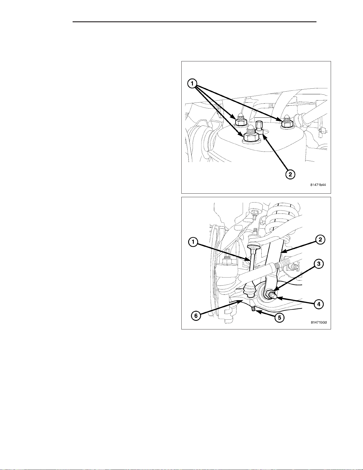
2 - 32 FRONT ND
INSTALLATION
NOTE: All suspension components should be tighten with the weight of the vehicle on them (curb height).
1. Install the upper part of the shock (2) into the
frame bracket.
2. Install the upper nuts (1). Tighten to 102 N·m (75 ft.
lbs.).
3. Install the lower part of the shock (2) into the lower
control arm shock bushing.
4. Position shock module clevis (2) to lower control
(6). Install bolt (4) so head of bolt is facing rear of
vehicle and hand start nut (3). Tighten the bolt (4)
& nut (5) to 81 N·m (60 ft. lbs.).
5. Install the stabilizer link lower nut (5) to the lower
control arm (6) (Refer to 2 - SUSPENSION/
FRONT/STABILIZER LINK - INSTALLATION).
6. Remove the support from the lower control arm outboard end.
7. Install the tire and wheel assembly (Refer to 22 - TIRES/WHEELS/WHEELS - STANDARD PROCEDURE).
8. Remove the support and lower the vehicle.
Page 64
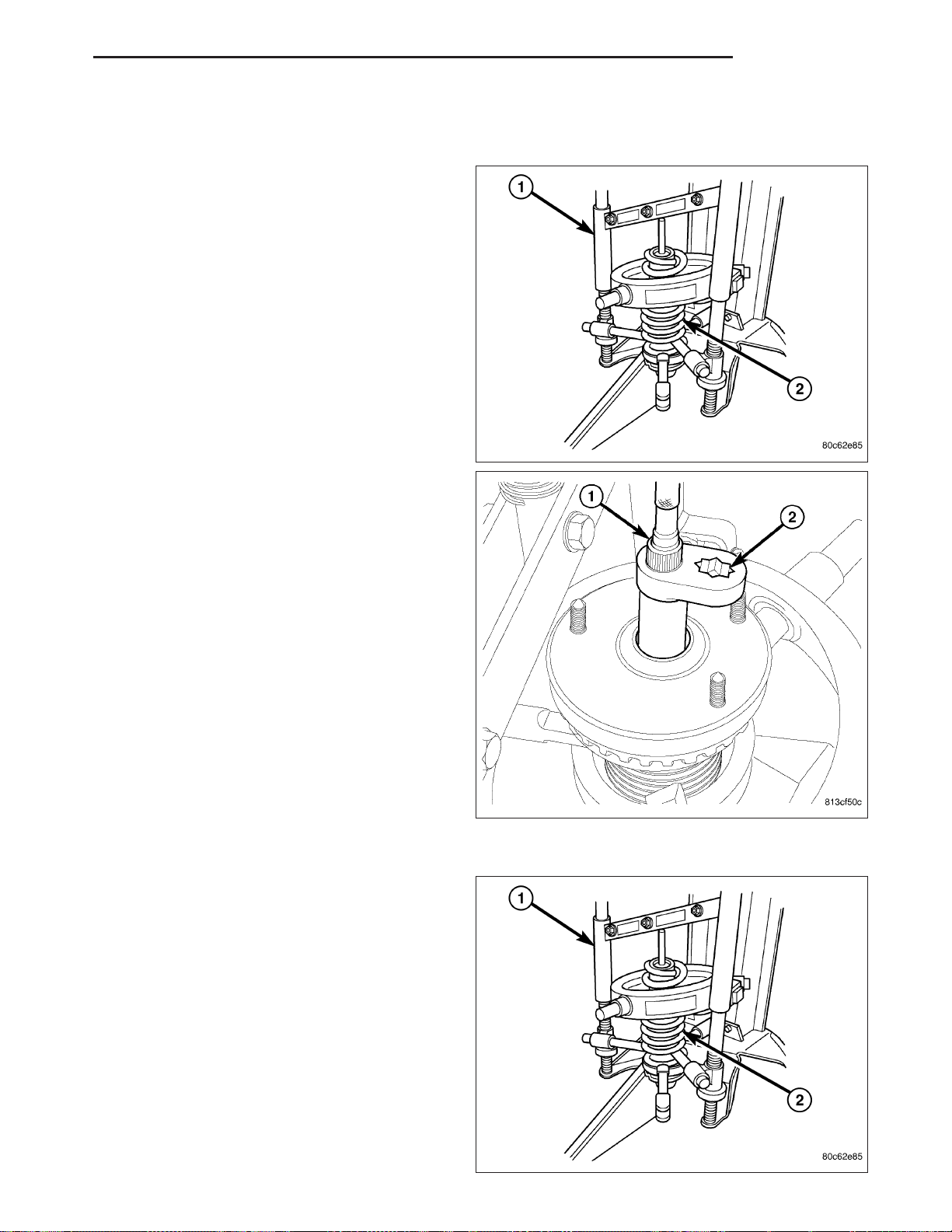
ND FRONT 2 - 33
SPRING
REMOVAL
1. Remove the shock (Refer to 2 - SUSPENSION/
FRONT/SHOCK - REMOVAL).
2. Install the shock assembly in the Branick 7200T
spring removal/installation tool or equivalent (1).
3. Compress the spring (2).
4. Position Wrench (2), Special Tool 9362, on shock
shaft retaining nut. Next, insert 8 mm socket
though Wrench onto hex located on end of shock
shaft. While holding shock shaft from turning,
remove nut from shock shaft using Wrench.
5. Remove the upper shock nut.
6. Remove the shock.
7. Remove the shock upper mounting plate.
8. Remove and inspect the upper and lower spring
isolators.
INSTALLATION
1. Install the lower isolator.
2. Install the upper isolator.
3. Position the shock into the coil spring.
4. Install the upper shock mounting plate.
Page 65
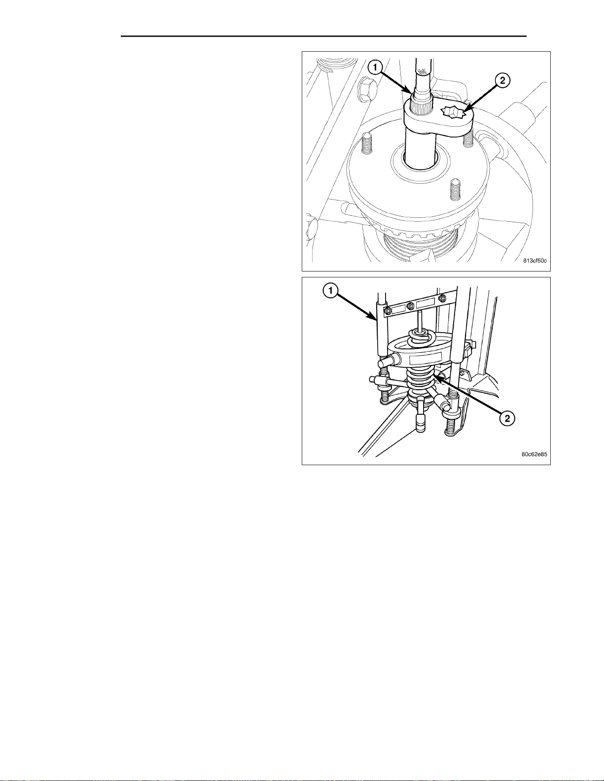
2 - 34 FRONT ND
5. Install Wrench (on end of a torque wrench), Special
Tool 9362, on shock shaft retaining nut. Next, insert
8 mm socket though Wrench onto hex located on
end of shock shaft. While holding shock shaft from
turning, tighten nut using Wrench to 90 N·m (66 ft.
lbs.) torque.
6. Install the shock upper mounting nut.
7. Decompress the spring (2).
8. Remove the shock assembly from the spring compressor tool (1).
9. Install the shock assembly (Refer to 2 - SUSPENSION/FRONT/SHOCK - INSTALLATION).
STABILIZER BAR
DESCRIPTION
The bar extends across the front underside of the chassis and connects to the frame crossmember. The ends of the
bar mount to the lower suspension arm. All mounting points of the stabilizer bar are isolated by bushings.
OPERATION
The stabilizer bar is used to minimize vehicle front sway during turns. The bar helps to maintain a flat attitude to the
road surface.
Page 66
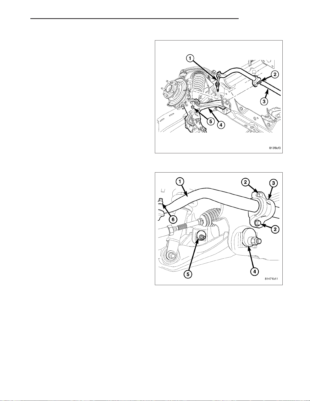
ND FRONT 2 - 35
REMOVAL
1. Remove the stabilizer link (1) upper nut and
remove the retainers and grommets (Refer to 2 SUSPENSION/FRONT/STABILIZER LINK REMOVAL).
2. Remove the stabilizer bar retainer bolts (2) also
remove the retainers from the frame sway bar and
remove the bar (3).
3. If necessary, remove the bushings from the stabilizer bar.
INSTALLATION
1. If removed, install the bushings on the stabilizer
bar.
2. Position the stabilizer bar (1) on the frame crossmember brackets and install the bracket (3) and
bolts (2) finger-tight.
NOTE: Check the alignment of the bar to ensure
there is no interference with the either frame rail
or chassis component. Spacing should be equal
on both sides.
3. Install the stabilizer bar (1) to the stabilizer link and
install the grommets and retainers.
4. Install the nuts (6) to the stabilizer link and tighten
to 169 N·m (125 ft. lbs.) (Refer to 2 - SUSPENSION/FRONT/STABILIZER LINK - INSTALLATION).
5. Tighten the bracket bolts (2) to the frame to 61N·m
(45 ft. lbs.).
Page 67
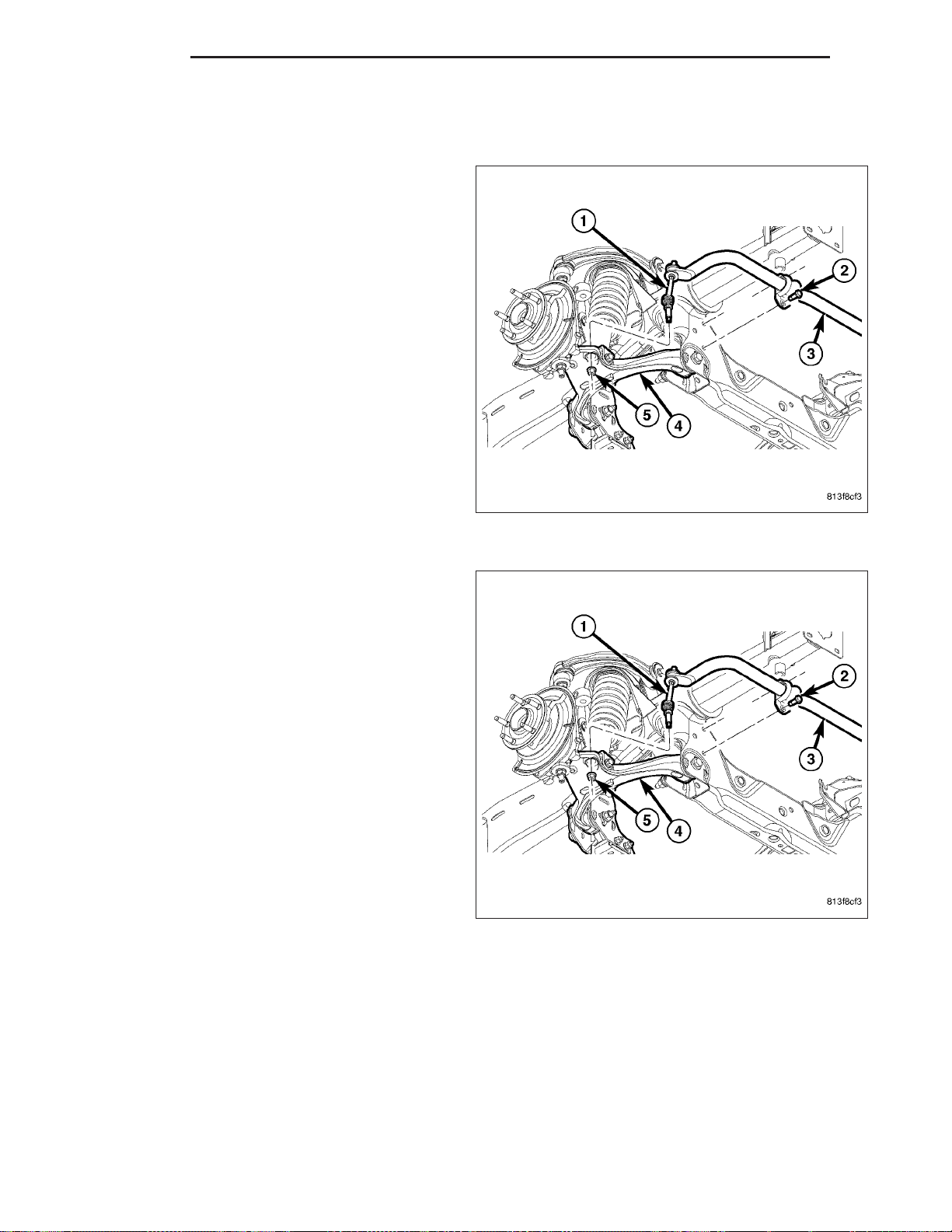
2 - 36 FRONT ND
STABILIZER LINK
REMOVAL
1. Raise and support the vehicle.
2. Remove the lower nut (5).
3. Remove the upper nut, retainers and grommets
from the stabilizer bar (3).
4. Remove the stabilizer link (1) from the vehicle.
INSTALLATION
1. Install the stabilizer link (1) to the vehicle.
2. Install the retainers, grommets and upper nut to the
stabilizer bar (3) and Tighten to 37 N·m (27 ft. lbs.).
3. Install the lower nut (5) and Tighten to 169 N·m
(125 ft. lbs.).
4. Remove the support and lower the vehicle.
Page 68
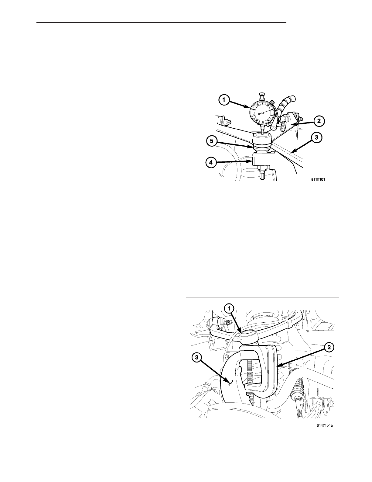
ND FRONT 2 - 37
UPPER BALL JOINT
DIAGNOSIS AND TESTING
UPPER BALL JOINT
1. Raise the front of the vehicle. Place safety floor
stands under both lower control arms as far outboard as possible. Lower the vehicle to allow the
stands to support some or all of the vehicle weight.
2. Remove the front tires.
3. Mount a dial indicator (1) solidly to the frame and
then zero the dial indicator.
4. Position dial indicator plunger on the topside of the
upper ball joint (5).
NOTE: The dial indicator plunger must be perpendicular to the machined surface of the ball joint.
NOTE: Use care not to pry or tear the ball joint
boot, when checking the free play.
5. Position a pry bar (3) between the steering knuckle (4) and the upper control arm (2). Pry upwards on the upper
control arm.
6. If the travel exceeds 0.5 mm (0.020 in.), replace the upper control arm since the upper ball joint is integral to the
arm (Refer to 2 - SUSPENSION/FRONT/UPPER CONTROL ARM - REMOVAL).
7. If the upper ball joint is within specs reinstall the front tires (Refer to 22 - TIRES/WHEELS/WHEELS - STANDARD PROCEDURE).
UPPER CONTROL ARM
REMOVAL
1. Raise and support vehicle.
2. Remove wheel and tire assembly.
3. Remove the nut from upper ball joint.
4. Separate upper ball joint (1) from the steering
knuckle (3) with Remover 8677 (2).
CAUTION: When installing Remover 8677 (2) to
separate the ball joint, be careful not to damage
the ball joint seal.
Page 69
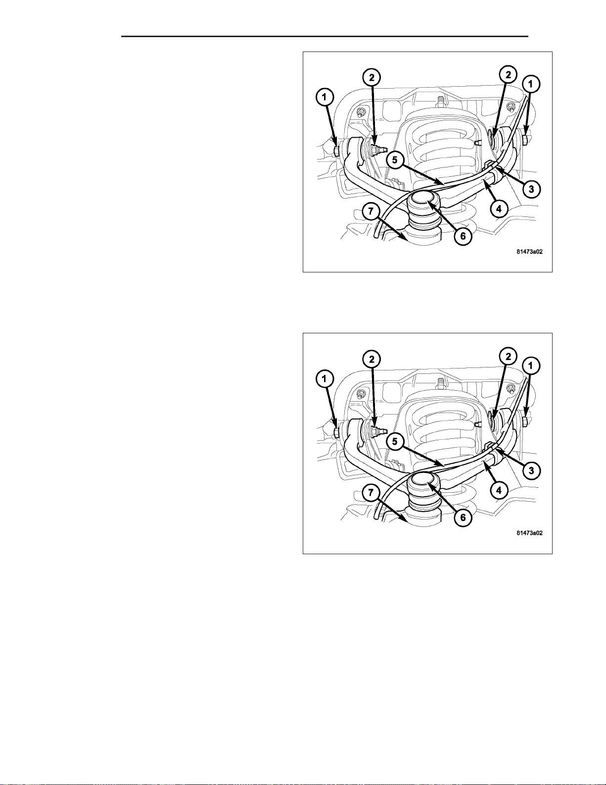
2 - 38 FRONT ND
5. Remove the wheel speed sensor wire (5) from the
retaining brackets (3) to the upper control arm (4).
6. Remove the control arm pivot bolts(1) and nuts (2)
and remove control arm (4).
INSTALLATION
NOTE: All suspension components should be tighten with the weight of the vehicle on them (curb height).
1. Position the control arm (4) into the frame brackets.
Install bolts (1) and nuts (2). Tighten to 102 N·m
(75 ft. lbs.).
2. Reposition the wheel speed wire (5) into the retaining brackets (3).
3. Insert ball joint (6) in steering knuckle (7) and
tighten ball joint nut to 75 N·m (55 ft. lbs.).
4. Install the wheel and tire assembly, (Refer to 22 - TIRES/WHEELS/WHEELS - STANDARD PROCEDURE).
5. Remove the support and lower vehicle.
6. Perform a wheel alignment, (Refer to 2 - SUSPENSION/WHEEL ALIGNMENT - STANDARD PROCEDURE).
Page 70
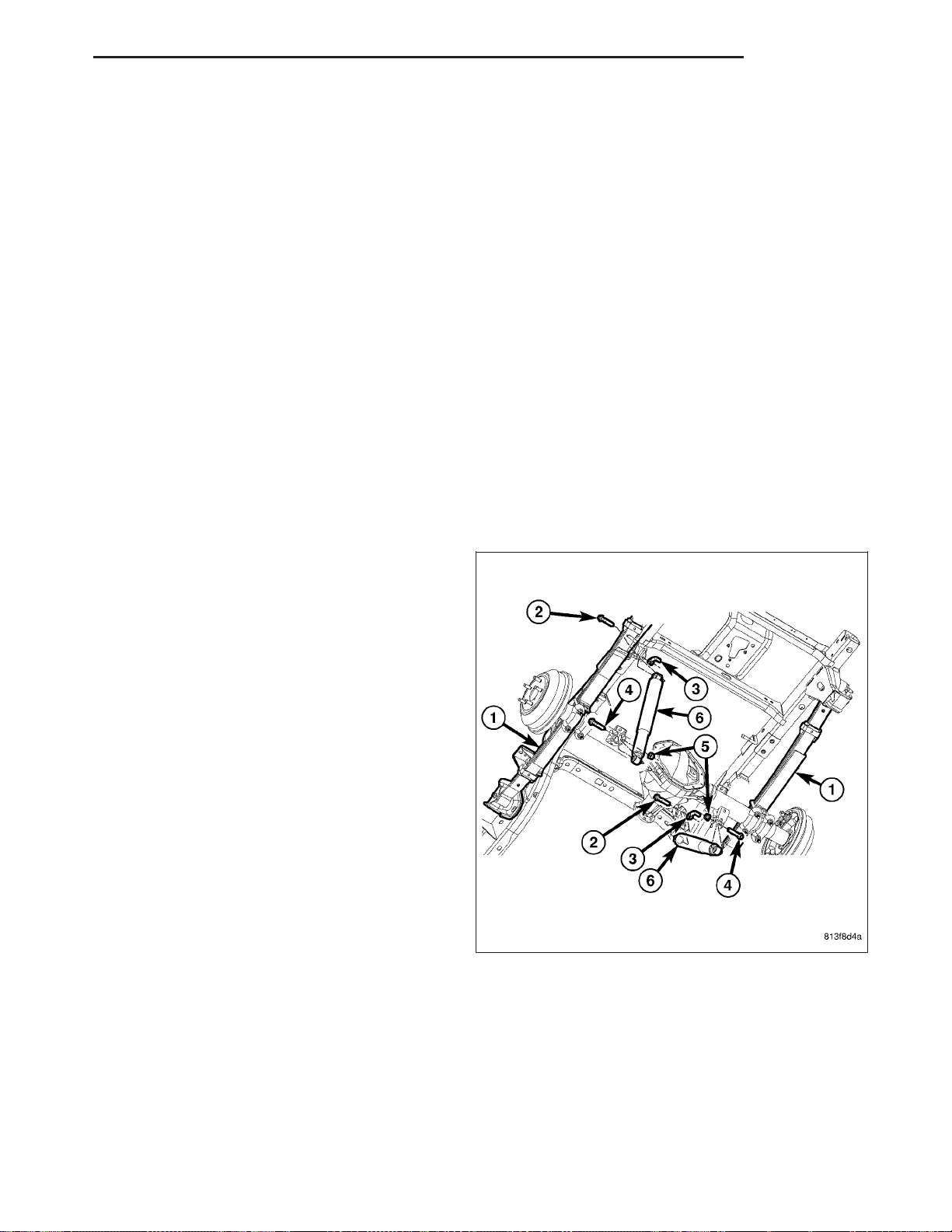
ND REAR 2 - 39
REAR
TABLE OF CONTENTS
page page
REAR
DESCRIPTION .........................39
DIAGNOSIS AND TESTING - REAR
SUSPENSION ........................40
SPECIFICATIONS
TORQUE CHART ......................40
JOUNCE BUMPER
REMOVAL .............................41
INSTALLATION .........................41
SHOCK
REMOVAL .............................42
INSTALLATION .........................43
REAR
DESCRIPTION
The rear suspension is comprised of:
• Shock Absorbers (6)
• Jounce Bumpers
• Stabilizer Bar
• Stabilizer links
• Leaf Springs (1)
• Drive Axle
SPRING
REMOVAL .............................45
INSTALLATION .........................46
STABILIZER LINK
REMOVAL .............................49
INSTALLATION .........................50
STABILIZER BAR
DESCRIPTION .........................50
OPERATION ...........................50
REMOVAL .............................51
INSTALLATION .........................52
CAUTION: A vehicle should always be loaded so
the vehicle weight center-line is located immediately forward of the rear axle. Correct vehicle loading provides proper front tire-to-road contact. This
results in maximum vehicle handling stability and
safety. Incorrect vehicle weight distribution can
cause excessive tire tread wear, spring fatigue or
failure, and erratic steering.
Page 71
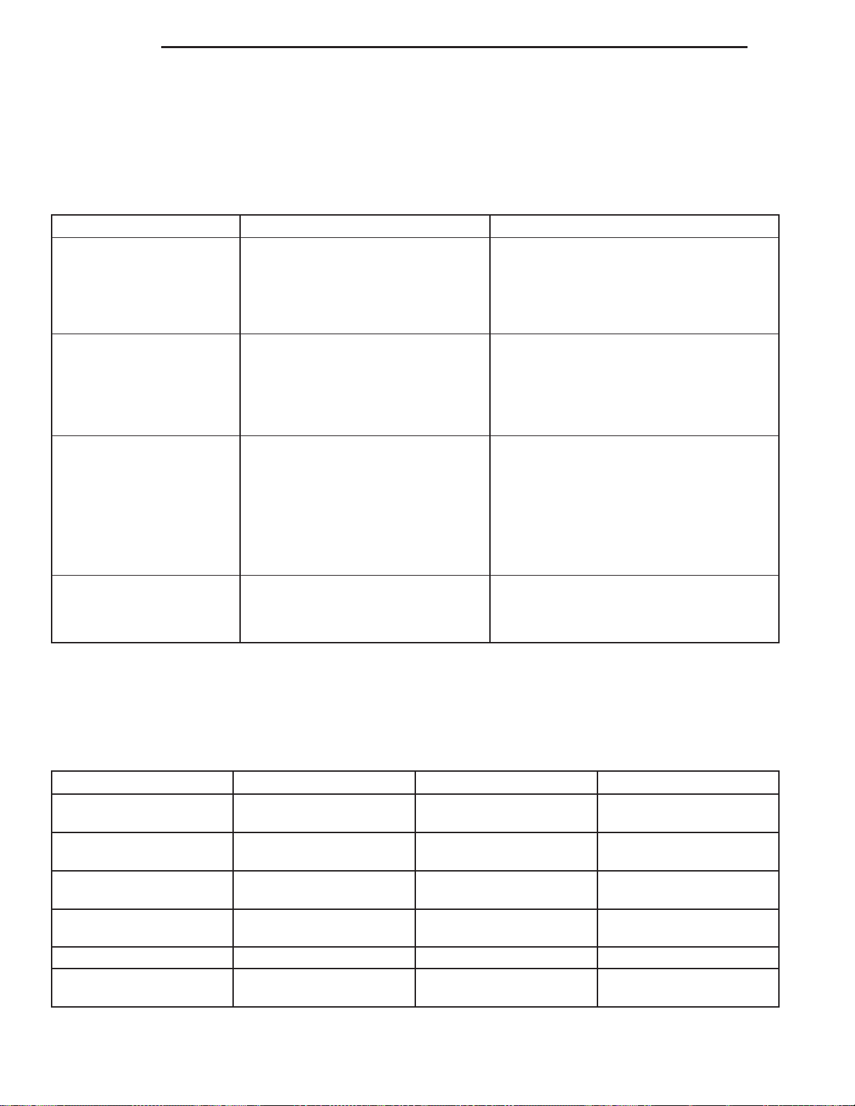
2 - 40 REAR ND
CAUTION: Suspension components with rubber/urethane bushings (except stabilizer bar) should be tightened with the vehicle at normal ride height. It is important to have the springs supporting the weight of the
vehicle when the fasteners are torqued. If springs are not at their normal ride position, vehicle ride comfort
could be affected and premature bushing wear may occur.
DIAGNOSIS AND TESTING - REAR SUSPENSION
CONDITION POSSIBLE CAUSES CORRECTION
VEHICLE INSTABILITY 1. Loose or worn wheel bearings. 1. Replace wheel bearings.
2. Loose, worn or bent suspension
components.
3. Tire pressure. 3. Adjust tire pressure.
VEHICLE PULLS TO ONE
SIDE
KNOCKING, RATTLING
OR SQUEAKING
IMPROPER TRACKING 1. Loose, worn or bent suspension
1. Weak or broken spring. 1. Replace spring.
2. Alignment. 2. Align vehicle to specifications.
3.Tires. 3. Replace tires.
4. Brakes. 4. Repair as necassary.
1. Worn shock bushings. 1. Replace shock.
2. Loose shock mounting. 2. Tighten to specifications.
3. Shock valve. 3. Replace shock.
4. Weak or broken spring. 4. Replace spring.
5. Loose, worn or bent suspension
components.
components.
2. Bent axle. 2.Replace axle.
SPECIFICATIONS
2. Inspect, tighten or replace components
as necessary.
5. Inspect, tighten or replace components
as necessary.
1. Inspect, tighten or replace components
as necessary.
TORQUE CHART
TORQUE SPECIFICATIONS
DESCRIPTION N·m Ft. Lbs. In. Lbs.
Shock Absorber
Lower Nut
Shock Absorber
Upper Bolt
Stabilizer Retainer to the
Axle
Stabilizer Link to Stabilizer
Bar
Stabilizer Link to Frame 102 75 —
Jounce Bumper
Bolts
102 75 —
102 75 —
61 45 —
102 75 —
41 30 —
Page 72
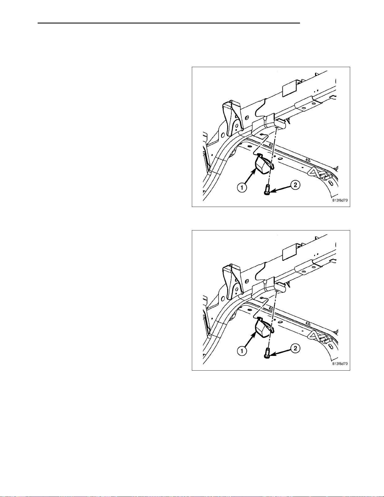
ND REAR 2 - 41
JOUNCE BUMPER
REMOVAL
1. Raise and support the vehicle.
2. Remove the bolts (2) securing the jounce bumper
(1).
3. Remove the jounce bumper (1).
INSTALLATION
1. Install the jounce bumper (1) and bolts (2). Tighten
to 41 N·m (30 ft.lbs.).
2. Remove the support and lower the vehicle.
Page 73
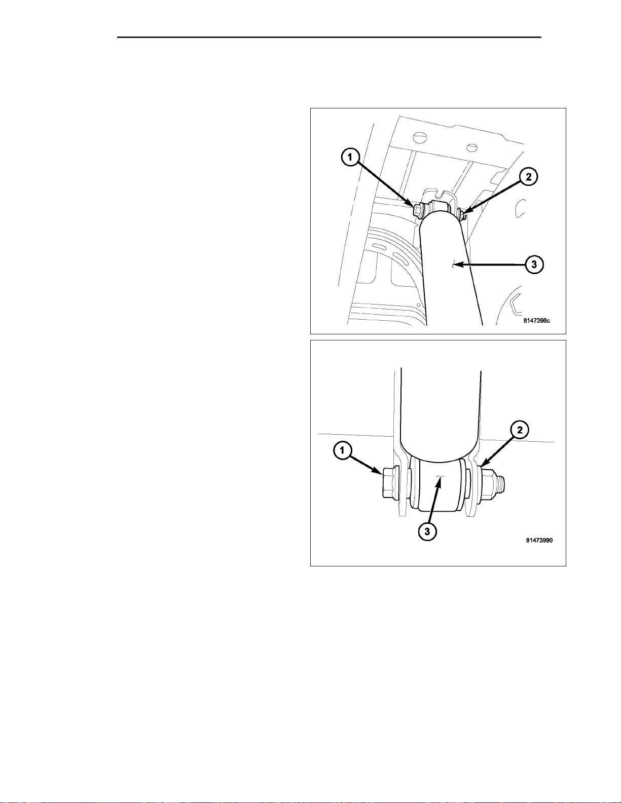
2 - 42 REAR ND
SHOCK
REMOVAL
1. Raise vehicle and support the axle.
2. Remove the upper shock bolt (1) and nut (2).
3. Remove the lower shock bolt (1) and nut (2).
Page 74
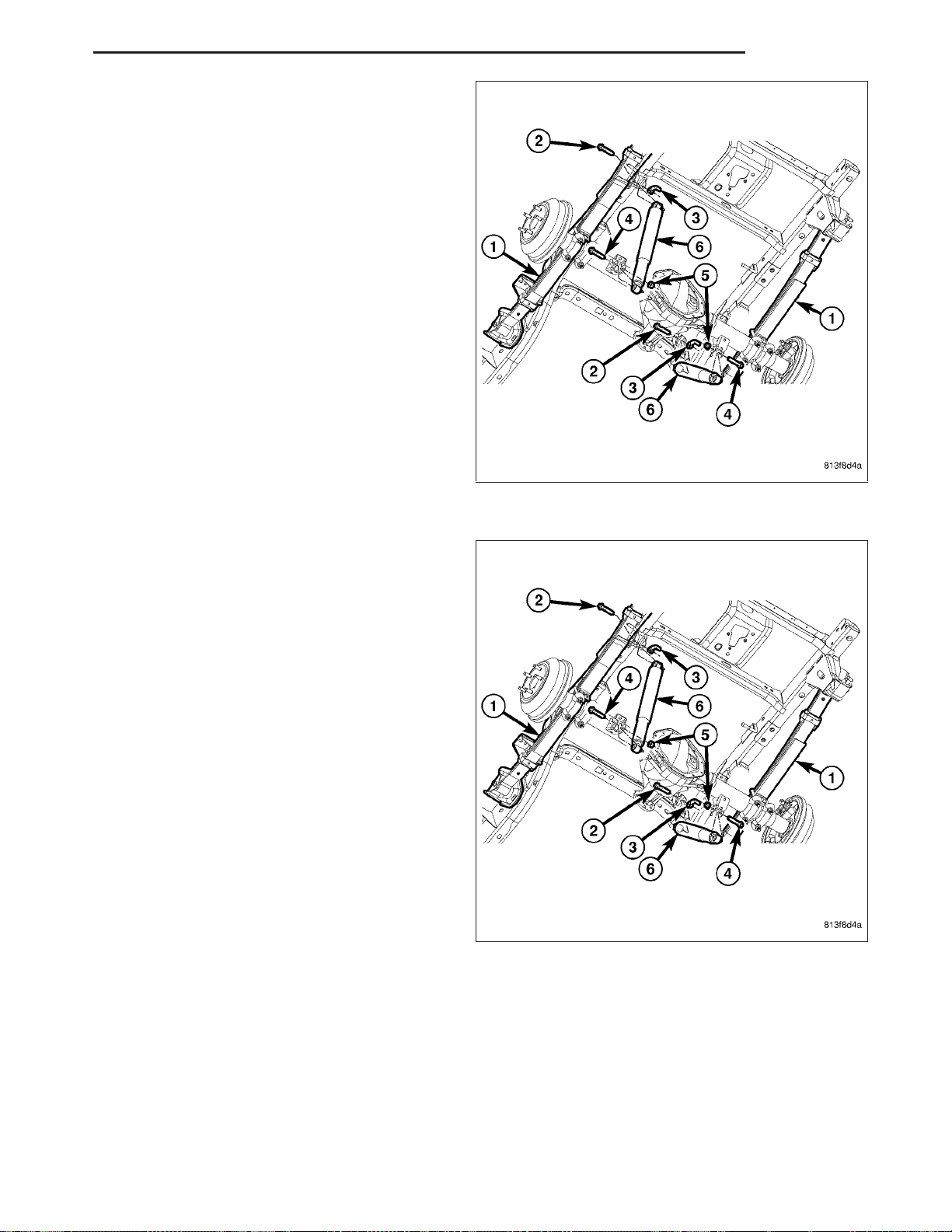
ND REAR 2 - 43
4. Remove the rear shock absorber (6) from the
vehicle.
INSTALLATION
1. Position the shock absorber (6) to the vehicle.
Page 75
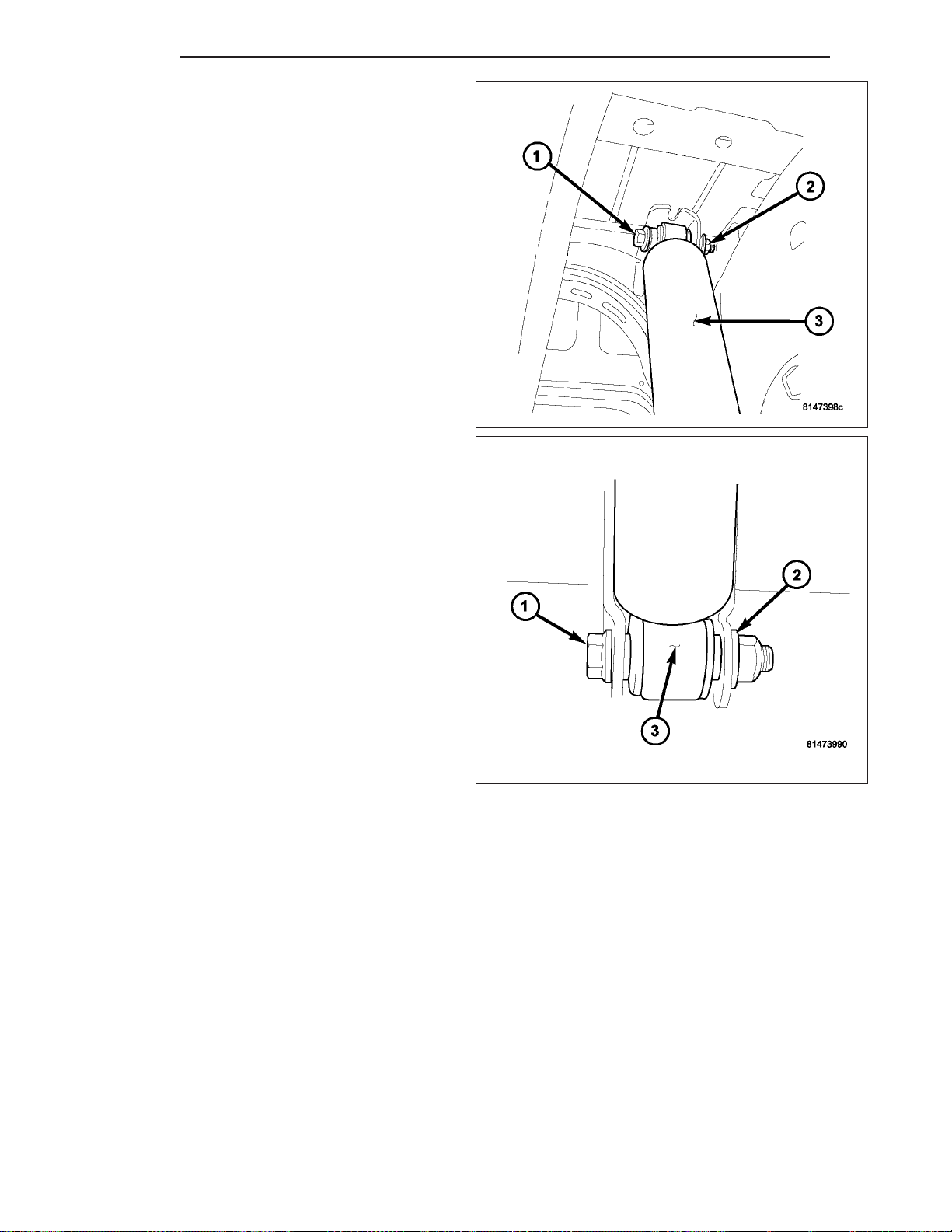
2 - 44 REAR ND
2. Install the bolt (1) through the frame bracket and
the shock (3). Install the nut (2) to the top bolt (1).
Tighten to 102 N.m (75 ft. lbs.)
3. Install the bolt (1) through the axle bracket and the
shock (3). Install the nut (2) to the bolt (1). Tighten
to 102 N.m (75 ft. lbs.)
4. Remove the support and lower the vehicle.
Page 76
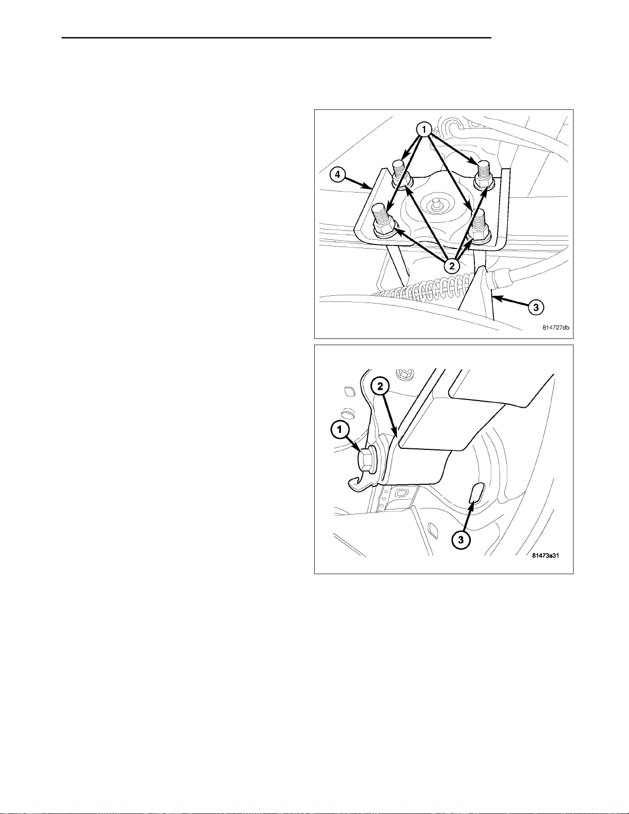
ND REAR 2 - 45
SPRING
REMOVAL
CAUTION: The rear of the vehicle must be lifted
only with a jack or hoist. The lift must be placed
under the frame rail crossmember located aft of
the rear axle. Use care to avoid bending the side
rail flange.
1. Raise the vehicle at the frame.
2. Use a hydraulic jack to relieve the axle weight.
3. Remove the wheel and tire assemblies.
4. Remove the nuts (2), the U-bolts (1) and spring
plate (4) from the axle.
5. Loosen and remove the bolt (1) and then remove
the flag nut through the access hole (3) in the
bracket from the spring front eye (2).
Page 77
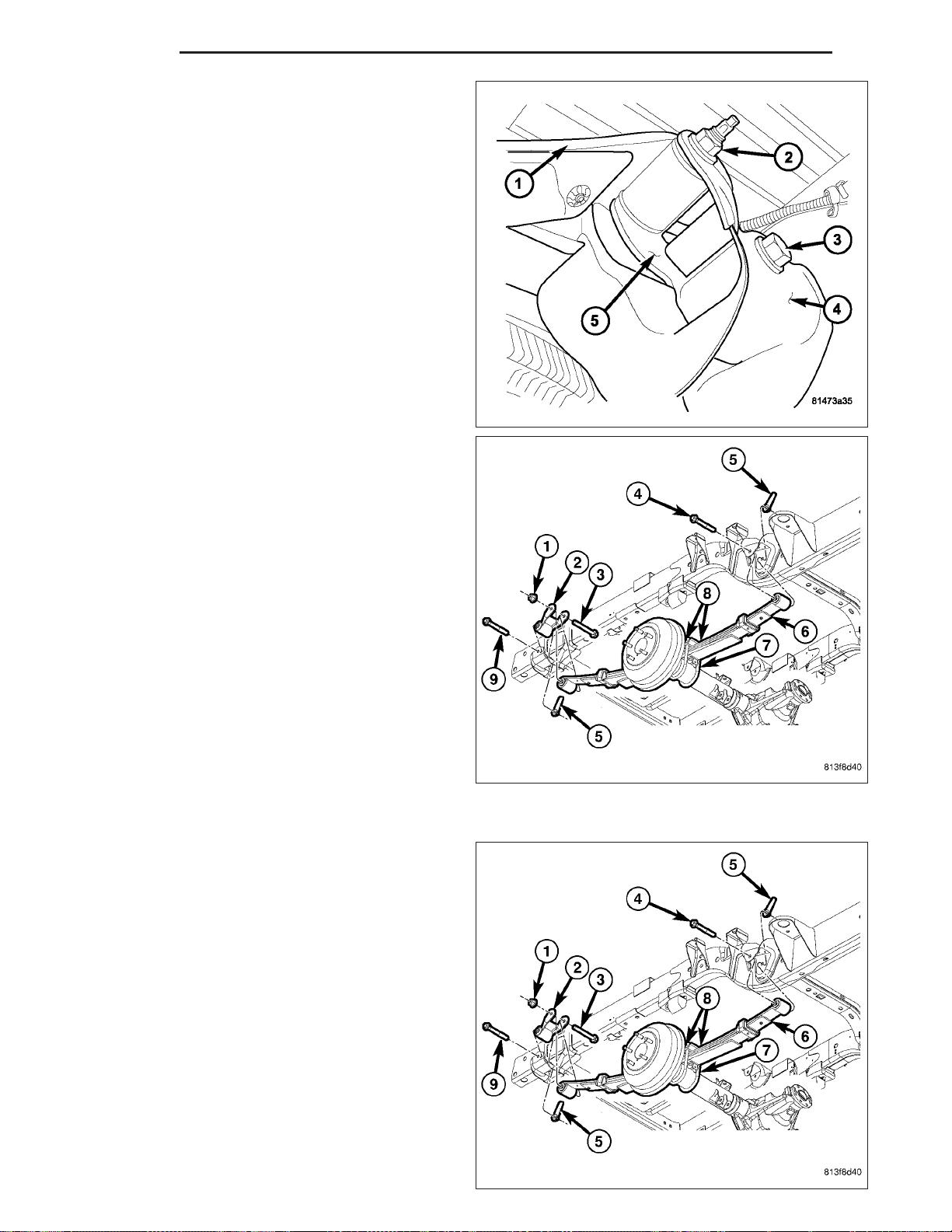
2 - 46 REAR ND
6. Remove the nut and bolt (3) that attaches the
spring shackle (5) to the rear frame bracket (4).
7. Remove the spring (6) from the vehicle.
8. Remove the shackle (2) from the spring (6).
INSTALLATION
CAUTION: The rear of the vehicle must be lifted
only with a jack or hoist. The lift must be placed
under the frame rail crossmember located aft of
the rear axle. Use care to avoid bending the side
rail flange.
1. Install the spring shackle (2) on the spring (6) finger tight.
2. Position the spring (6) on the rear axle pad. Make
sure the spring center bolt is inserted in the pad
locating hole.
Page 78
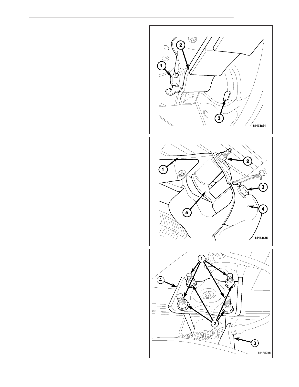
ND REAR 2 - 47
3. Align front spring eye (2) with the bolt hole in the
front frame bracket. Install the spring eye bolt (1)
and flag nut through the access hole in the frame
(3) and tighten the bolt (1) finger-tight.
4. Align spring shackle eye with the bolt hole in the
rear frame bracket (4). Install the bolt (3) and nut
and tighten the spring shackle eye nut finger-tight.
5. Install the U-bolts (1), spring plate (4) and nuts (2).
6. Tighten the U-bolt nuts (2) to 149 N·m (110 ft. lbs.).
7. Install the wheel and tire assemblies. (Refer to 22 - TIRES/WHEELS/WHEELS - STANDARD PROCEDURE).
Page 79
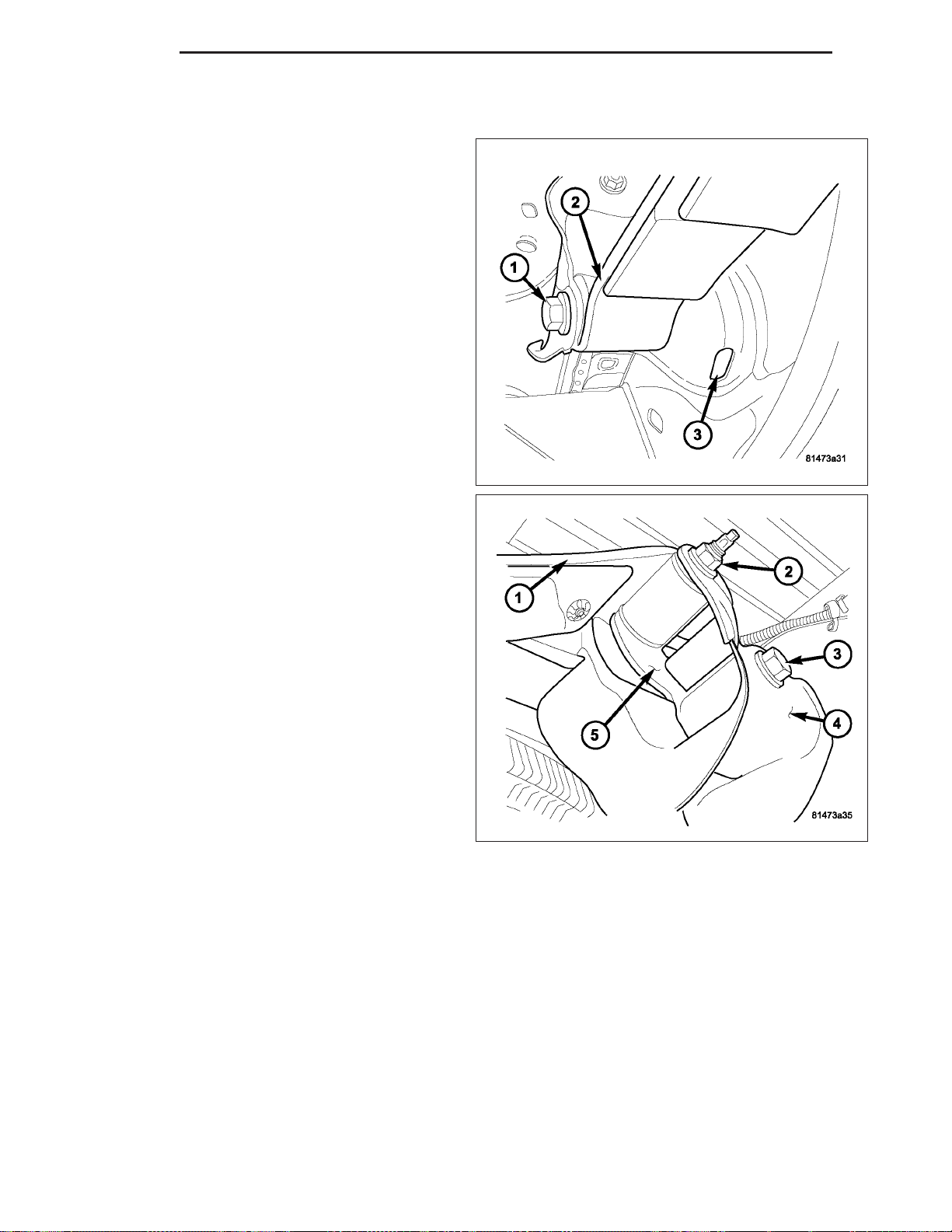
2 - 48 REAR ND
8. Remove the support stands from under the frame rails. Lower the vehicle until the springs are supporting the
weight of the vehicle.
9. Tighten the spring eye pivot bolt (1) and flagnut to
163 N·m (120 ft. lbs.).
10. Tighten the upper shackle bolt and nut (2) and the
lower shackle bolt (3) and nut to 163 N·m (120 ft.
lbs.).
Page 80
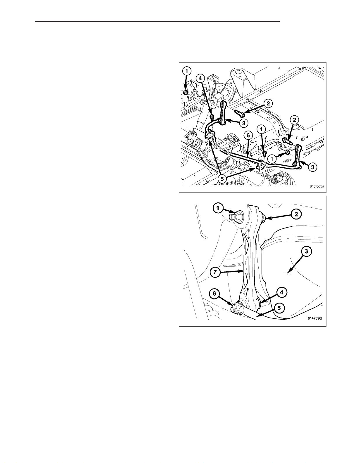
ND REAR 2 - 49
STABILIZER LINK
REMOVAL
1. Raise and support the vehicle.
2. Remove the rear tire.
3. Support the rear axle with a jack.
4. Remove the lower link nut (4) at the stabilizer bar
(6).
5. Remove the upper link nut (1) and bolt (2) at the
frame. On the left side stabilizer link (7), upper
bolt pull the bolt (2) back after the nut (1) is
removed and then pull the link (7) downward
with the bolt (2) still in the link (7) to allow
clearance from the fuel tank (3).
6. Remove stabilizer link (7).
Page 81
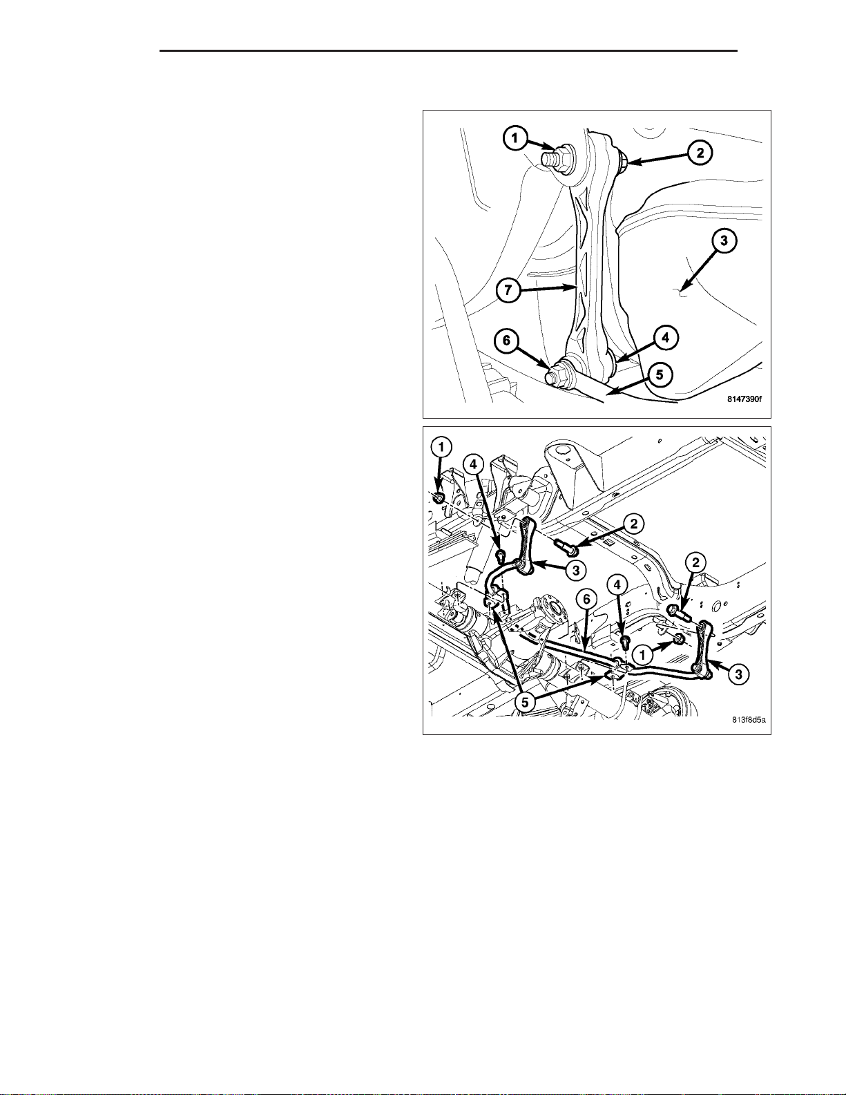
2 - 50 REAR ND
INSTALLATION
1. Install the upper bolt (2) into the stabilizer link then
raise the link (7) into position with the frame and
install the nut (1) for the stabilizer link (7) to the
frame and tighten to 102 N·m (75 ft. lbs.).
2. Install the stabilizer link (3) to the stabilizer bar (6).
3. Install the nut (4) and tighten to 102 N·m (75 ft.
lbs.).
4. Remove the jack and lower the vehicle.
STABILIZER BAR
DESCRIPTION
The stabilizer bar extends across the underside of the vehicle and is bolted to the of the axle. The links are bolted
at the end of the bar and also bolted to the frame.
OPERATION
The stabilizer bar is used to minimize vehicle body sway. The spring steel bar helps to control the vehicle body in
relationship to the suspension.
Page 82
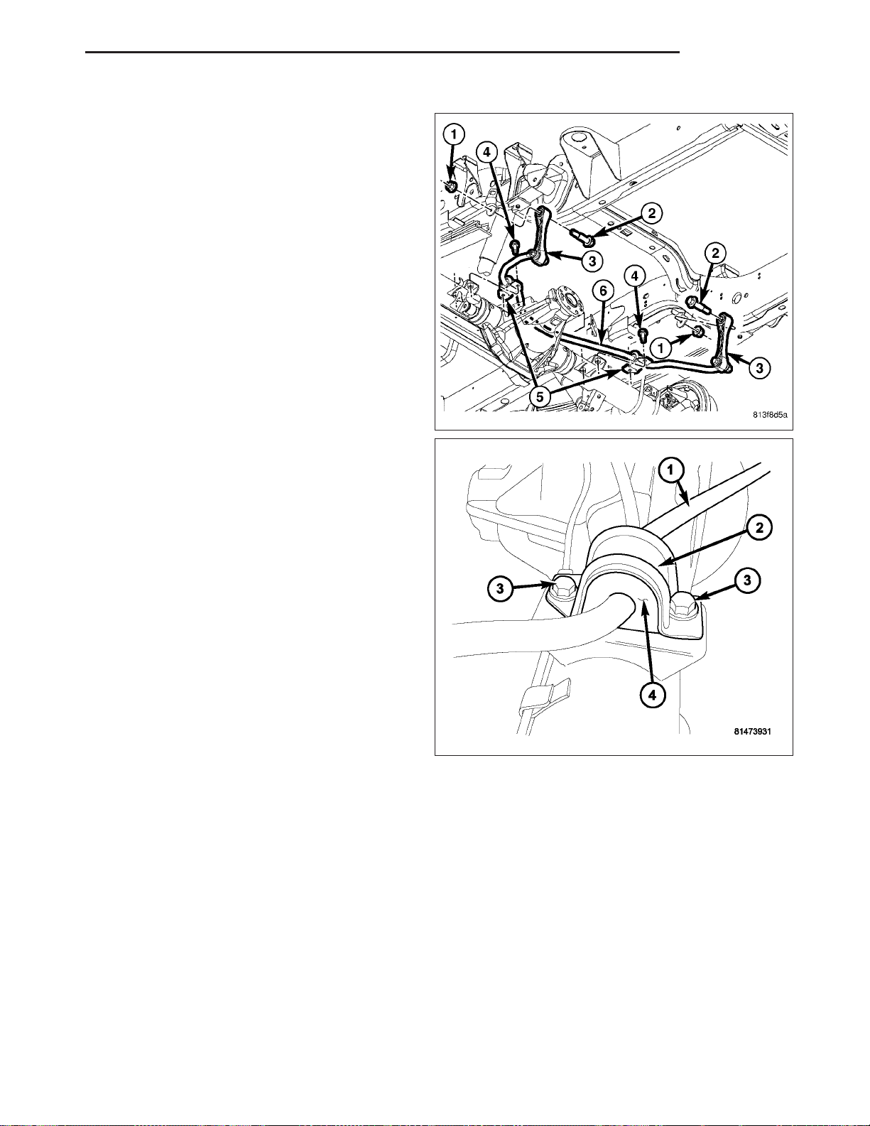
ND REAR 2 - 51
REMOVAL
1. Raise and support vehicle.
2. Remove nuts and bolts from the links (3) at the
stabilizer bar (6).
3. Remove stabilizer bar retainer bolts (3) and retainers (2).
4. Remove stabilizer bar (1) and replace worn,
cracked or distorted bushings (4).
Page 83
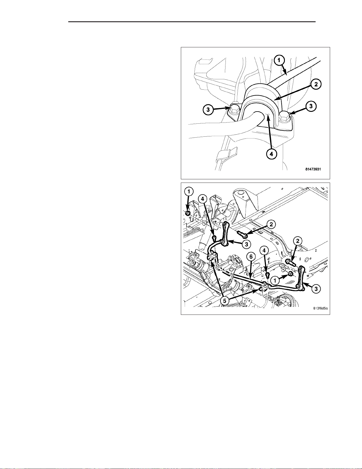
2 - 52 REAR ND
INSTALLATION
1. Install the stabilizer bushings (4).
2. Install the stabilizer bar (1) and center it with equal
spacing on both sides. Install stabilizer bar retainers (2) and tighten bolts (3) to 54 N·m (40 ft. lbs.).
3. Install link (3) into the stabilizer bar (6). Install
mounting nuts and bolts. Tighten stabilizer link nuts
to 54 N·m (40 ft. lbs.).
4. Remove support and lower vehicle.
Page 84

ND DIFFERENTIAL & DRIVELINE 3 - 1
DIFFERENTIAL & DRIVELINE
TABLE OF CONTENTS
page page
PROPELLER SHAFT ......................1
HALF SHAFT ...........................21
FRONT AXLE - C205F .....................32
PROPELLER SHAFT
TABLE OF CONTENTS
page page
PROPELLER SHAFT
DIAGNOSIS AND TESTING
PROPELLER SHAFT ....................1
STANDARD PROCEDURE
PROPELLER SHAFT ANGLE ..............4
SPECIFICATIONS ........................6
SPECIAL TOOLS ........................7
SHAFT-PROPELLER FRONT
REMOVAL ..............................8
INSTALLATION ..........................9
REAR AXLE-81/4 .......................71
REAR AXLE-91/4 ......................109
SHAFT-PROPELLER REAR
REMOVAL .............................10
INSTALLATION .........................11
UNIVERSAL JOINTS-SINGLE CARDAN
DISASSEMBLY
DISASSEMBLY - WITH SNAP RINGS .......11
DISASSEMBLY - WITH INJECTED RINGS . . . 13
ASSEMBLY
ASSEMBLY - WITH SNAP RINGS .........15
ASSEMBLY - WITH INJECTED RINGS ......16
PROPELLER SHAFT
DIAGNOSIS AND TESTING
PROPELLER SHAFT
PROPELLER SHAFT VIBRATION
Out-of-round tires or wheels that are out of balance, will cause a low frequency vibration.
Driveline vibration can also caused by loose or damaged engine mounts.
Propeller shaft vibration increases with vehicle speed. A vibration that occurs at a specific speed range, is not usu-
ally caused by an out of balance propeller shaft. Defective universal joints or an incorrect propeller shaft angle are
usually the cause of such a vibration.
Page 85
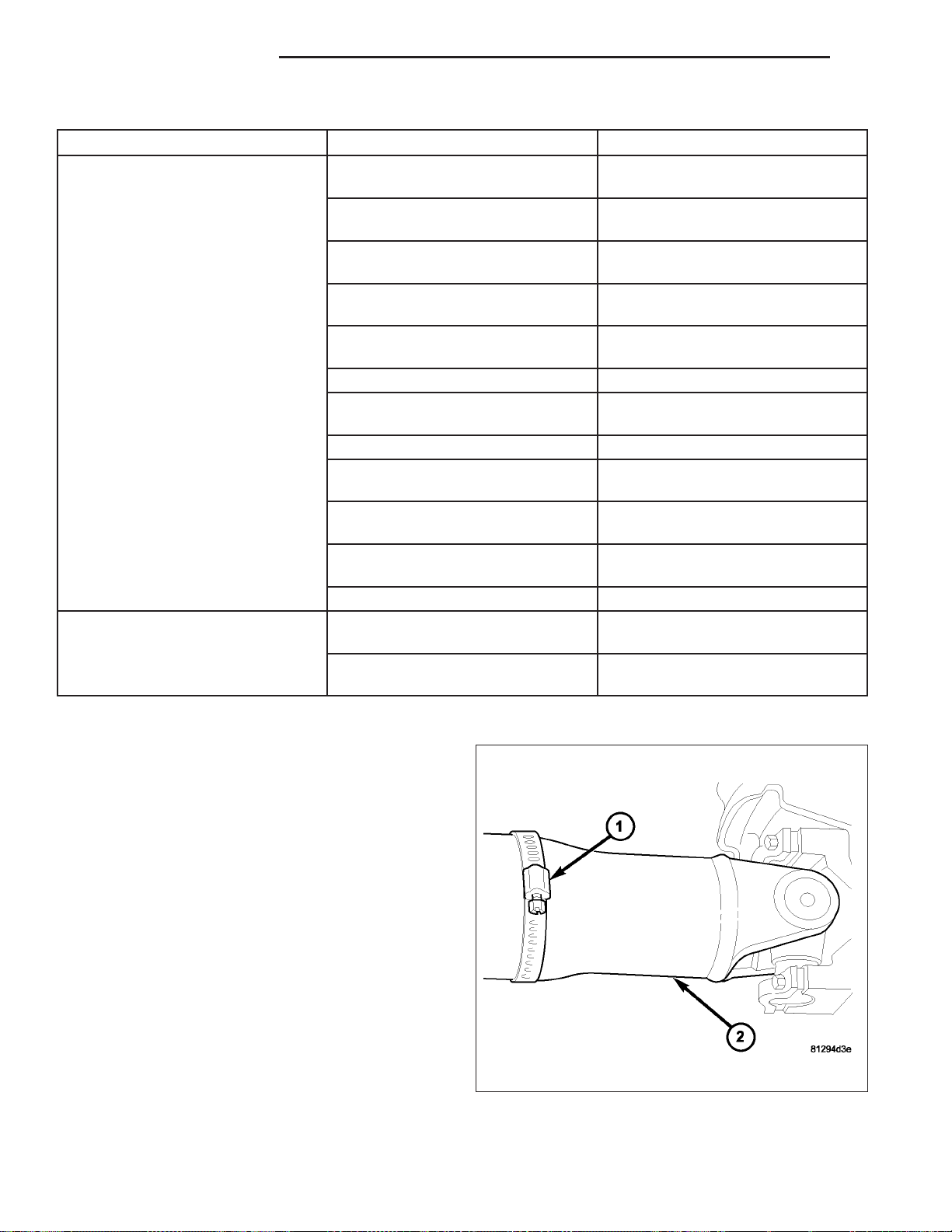
3 - 2 PROPELLER SHAFT ND
DRIVELINE VIBRATION
Drive Condition Possible Cause Correction
Propeller Shaft Noise 1) Undercoating or other foreign
material on shaft.
2) Loose U-joint clamp screws. 2) Install new clamps and screws
3) Loose or bent U-joint yoke or
excessive runout.
4) Incorrect driveline angularity. 4) Measure and correct driveline
5) Rear spring center bolt not in
seat.
6) Worn U-joint bearings. 6) Install new U-joint.
7) Propeller shaft damaged or out
of balance.
8) Broken rear spring. 8) Install new rear spring.
9) Excessive runout or unbalanced
condition.
10) Excessive drive pinion gear
shaft runout.
11) Excessive axle yoke deflection. 11) Inspect and replace yoke if
12) Excessive transfer case runout. 12) Inspect and repair as necessary.
Universal Joint Noise 1) Loose U-joint clamp screws. 1) Install new clamps and screws
2) Lack of lubrication. 2) Replace as U-joints as
1) Clean exterior of shaft and wash
with solvent.
and tighten to proper torque.
3) Install new yoke.
angles.
5) Loosen spring u-bolts and seat
center bolt.
7) Installl new propeller shaft.
9) Re-index propeller shaft, test,
and evaluate.
10) Re-index propeller shaft and
evaluate.
necessary.
and tighten to proper torque.
necessary.
PROPELLER SHAFT BALANCE
If propeller shaft is suspected of being out of balance,
use the following procedure.
NOTE: Indexing propeller shaft 180° relative to the
yoke may eliminate some vibrations.
1. Raise and support vehicle.
2. Clean all foreign material from the propeller shaft
and universal joints.
3. Inspect propeller shaft for missing balance weights,
broken welds and bent areas. If propeller shaft is
bent, it must be replaced.
4. Inspect universal joints for wear and properly
installed.
5. Check propeller shaft bolt torques.
6. Remove wheels and install lug nuts to retain brake
rotors.
7. Mark and number the shaft six inches from the pinion yoke end at four positions 90° apart.
8. Run and accelerate vehicle until vibration occurs. Note the intensity and speed the vibration occurred. Stop the
engine.
Page 86
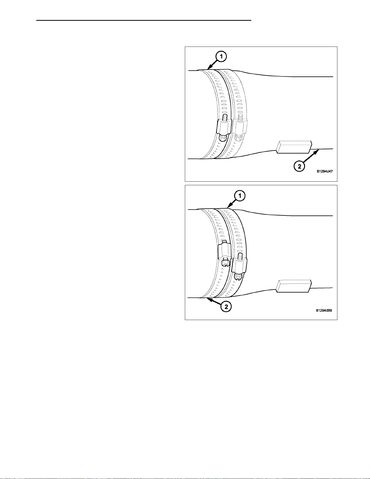
ND PROPELLER SHAFT 3 - 3
9. Install a screw clamp at position (1).
10. Start engine and check vibration. If there is little
or no change move the clamp to the next positions. Repeat the vibration test.
NOTE: If there is no difference in vibration at this
positions, the vibration may not be the propeller
shaft.
11. If vibration decreased, install a second clamp (1)
and repeat the test.
12. If additional clamp causes an additional vibration,
separate the clamps 1/2 inch (1) above and below
the mark. Repeat the vibration test.
13. Increase distance between the clamp screws (1)
(2) and repeat test, until the least amount of vibration is noticed. Bend the slack end of the clamps
so screws will not loosen.
14. If vibration remains unacceptable, repeat the pro-
cedure to the front end of the propeller shaft.
15. Install wheels and lower vehicle.
PROPELLER SHAFT RUNOUT
1. Clean propeller shaft surface, where dial indicator will contact the shaft.
2. Install dial indicator perpendicular to the shaft surface.
3. Measure runout at the center and ends of the shaft away from weld areas, so weld process does not affect
measurements.
4. Refer to Runout Specifications chart.
5. If runout is out of specification, index the shaft 180° and take shaft runout measurements again.
6. If runout is now within specifications, mark shaft and yokes for proper orientation.
7. If runout is not within specifications, verify runout of the transmission/transfer case and axle are within specifications. Correct as necessary and measure propeller shaft runout again.
8. Replace propeller shaft if the runout still exceeds the limits.
Page 87
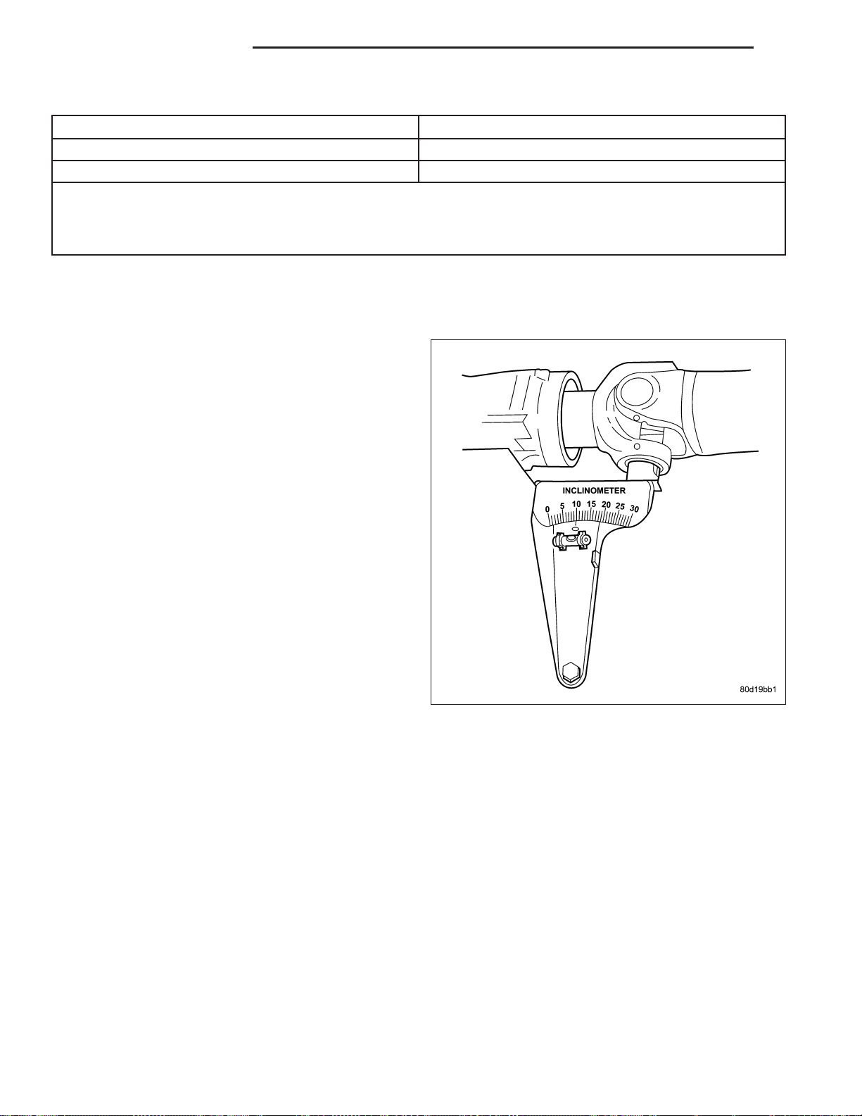
3 - 4 PROPELLER SHAFT ND
RUNOUT SPECIFICATIONS
Front of Shaft 0.020 in. (0.50 mm)
Center of Shaft 0.025 in. (0.63 mm)
Rear of Shaft 0.020 in. (0.50 mm)
NOTE:
Measure front/rear runout approximately 3 inches (76 mm) from the weld seam at each end of the shaft tube for
tube lengths over 30 inches. For tube lengths under 30 inches, the maximum allowed runout is 0.020 in. (0.50
mm) for the full length of the tube.
STANDARD PROCEDURE
PROPELLER SHAFT ANGLE
NOTE: This procedure applies to the front and rear
propeller shaft.
1. Raise and support vehicle at the axles as level as
possible, allowing wheels and propeller shaft to
turn.
2. Remove universal joint snap rings if equipped, so
inclinometer base will sits flat.
3. Rotate shaft until transmission/transfer case output
yoke bearing cap is facing downward.
NOTE: Always make measurements from front to
rear and from the same side of the vehicle.
4. Place Inclinometer 7663 on yoke bearing cap or
pinion flange ring, parallel to the shaft. Center bubble in sight glass and record measurement (A).
This measurement will give you the transmission
or Output Yoke Angle (A).
Page 88
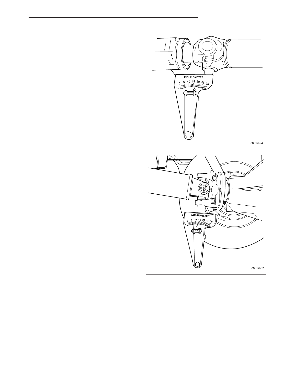
ND PROPELLER SHAFT 3 - 5
5. Rotate propeller shaft 90 degrees and place Inclinometer 7663 on yoke bearing cap parallel to the
shaft. Center bubble in sight glass and record measurement (C). This measurement can also be taken
at the rear end of the shaft.
This measurement will give you the propeller shaft
angle (C).
6. Subtract smaller figure from larger (C minus A) to
obtain transmission output operating angle.
7. Rotate propeller shaft 90 degrees and place Inclinometer 7663 on pinion yoke bearing cap parallel
to the shaft. Center bubble in sight glass and
record measurement (B).
This measurement will give you the pinion shaft or
input yoke angle (B).
8. Subtract smaller figure from larger (C minus B) to
obtain axle Input Operating Angle.
PROPELLER SHAFT ANGLE RULES
• Good cancellation of U-joint operating angles is within 1 degree.
• Operating angles less than 3 degrees.
• At least 1/2 of one degree continuous operating (propeller shaft) angle.
Page 89
3 - 6 PROPELLER SHAFT ND
SPECIFICATIONS
TORQUE SPECIFICATIONS
DESCRIPTION N·m Ft. Lbs. In. Lbs.
Center Bearing Bolts 68 50 -
Front Companion Flange
Bolts
Rear Companion Flange
Bolts
115 85 -
115 85 -
Page 90
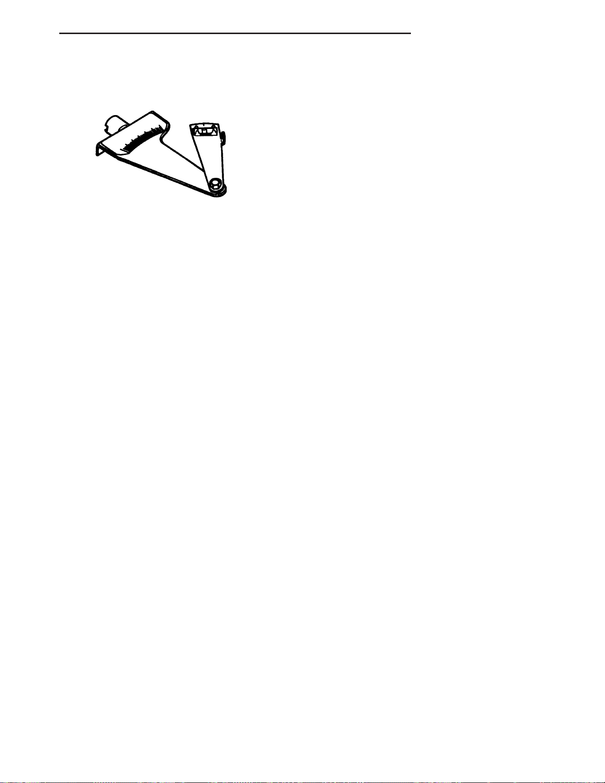
ND PROPELLER SHAFT 3 - 7
SPECIAL TOOLS
INCLINOMETER 7663
Page 91
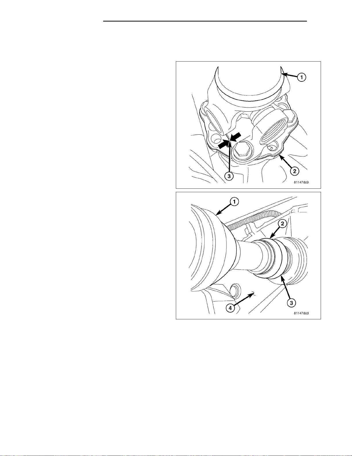
3 - 8 PROPELLER SHAFT ND
SHAFT-PROPELLER FRONT
REMOVAL
1. With vehicle in neutral, position vehicle on hoist.
2. Remove skid plate if equipped.
3. Mark a reference line (3) across propeller shaft
flange and pinion flange (2).
4. Remove exhaust crossover bolts from exhaust
manifolds and lower crossover.
5. Remove boot clamp (3) from CV joint (1).
6. Remove pinion flange bolts.
7. Slide propeller shaft off the transfer case and
remove shaft.
Page 92
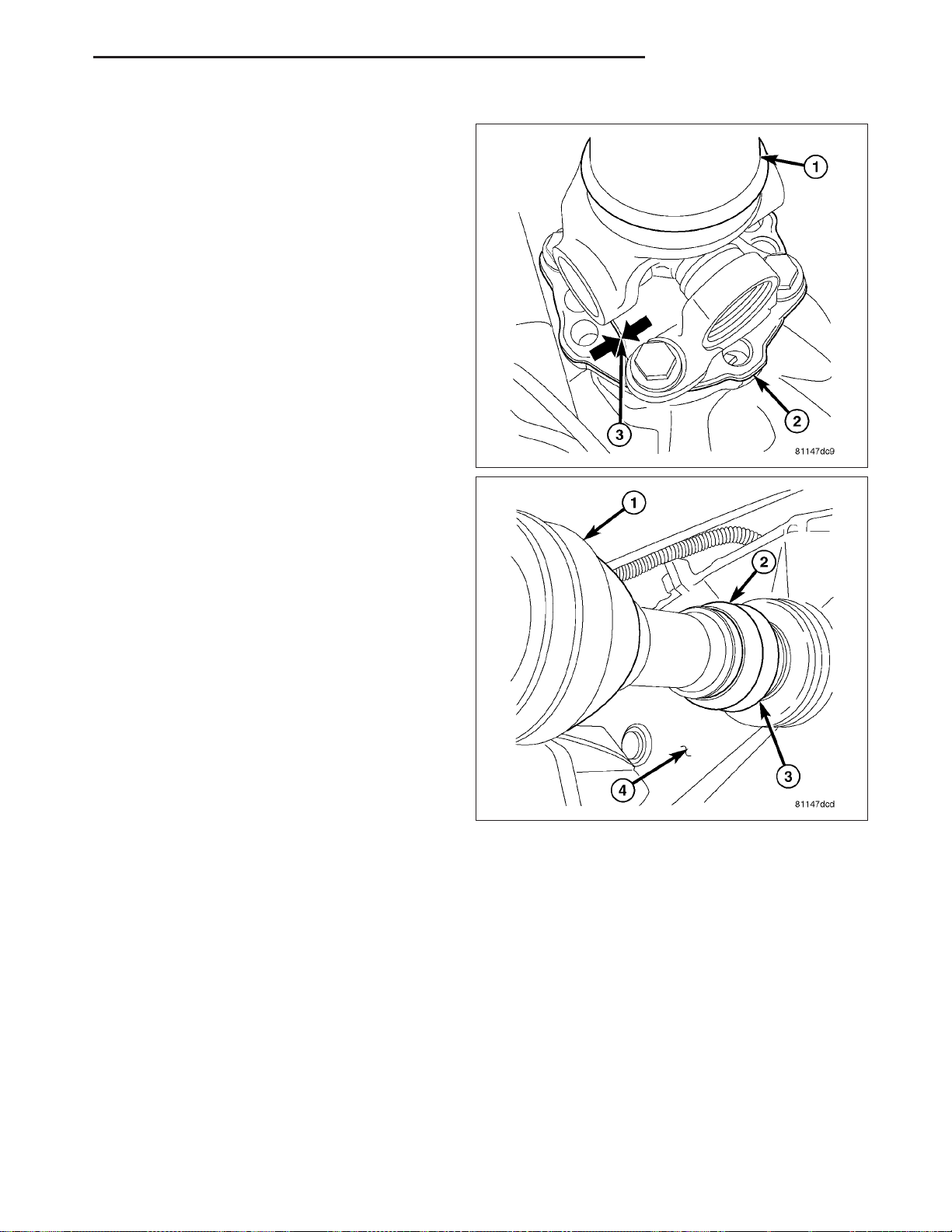
ND PROPELLER SHAFT 3 - 9
INSTALLATION
1. Slide propeller shaft onto transfer case.
2. Install propeller shaft with reference marks (3)
aligned on pinion flange.
3. Install new pinion flange bolts and tighten to 115
N·m (85 ft. lbs.).
NOTE: Flange bolts incorporate a LoctiteT patch,
new bolts should be used. If bolts are not available, clean bolts and apply LoctiteT 242 to the
threads.
4. Install CV boot clamp (3).
5. Install skid plate, if equipped.
Page 93
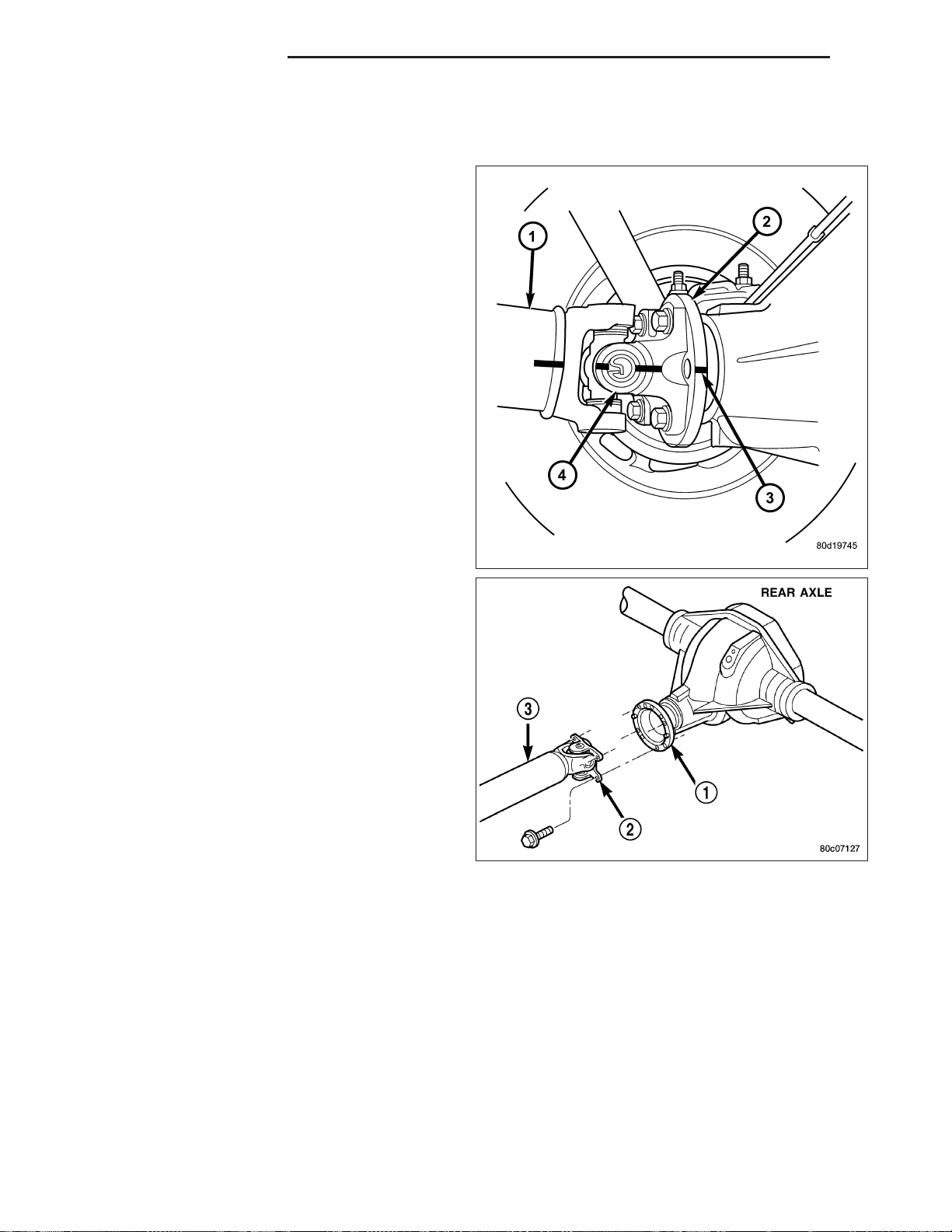
3 - 10 PROPELLER SHAFT ND
SHAFT-PROPELLER REAR
REMOVAL
1. With vehicle in neutral, position vehicle on hoist.
2. Mark a reference line (3) across the pinion flange
(2) and propeller shaft flange (4).
3. Remove flange bolts.
4. Slide slip yoke off of the transmission/transfer case
output shaft and remove propeller shaft (3).
Page 94
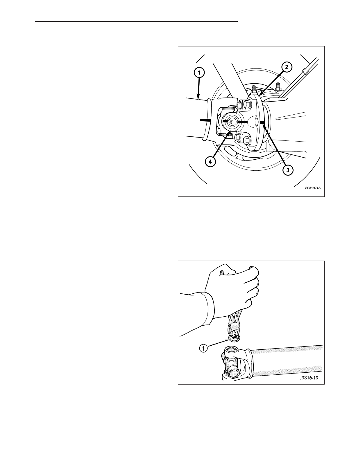
ND PROPELLER SHAFT 3 - 11
INSTALLATION
1. Slide slip yoke onto transmission/transfer case output shaft.
2. Align flange reference marks (3).
3. Install new flange bolts and tighten to 115 N·m (85
ft. lbs.).
NOTE: Flange bolts incorporate a LoctiteT patch,
new bolts should be used. If bolts are not available, clean bolts and apply LoctiteT 242 to the
threads.
UNIVERSAL JOINTS-SINGLE CARDAN
DISASSEMBLY
DISASSEMBLY - WITH SNAP RINGS
NOTE: This procedure describes a propeller shaft
equipped with a cardan joint in the tube yoke. For
propeller shafts equipped with a companion/slip
yoke, repeat the steps to remove the remaining
cardan joint.
1. Tap outside of bearing cap with a drift to loosen
snap ring.
2. Remove snap rings (1) from both sides of yoke.
Page 95
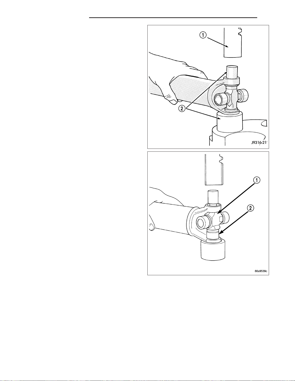
3 - 12 PROPELLER SHAFT ND
3. Position yoke with the grease fitting if equipped,
pointing up.
4. Position a socket with a inside diameter large
enough to receive the bearing cap, beneath the
yoke on a press.
5. Place another socket with an outside diameter
smaller than bearing cap on the upper bearing cap
and press (1) the lower cap through the yoke.
NOTE: If the bearing cap will not pull out of the
yoke by hand after pressing, tap the yoke ear near
the bearing cap to dislodge the cap.
6. Pull bearing cap of the yoke.
7. Turn yoke over in the press and straighten the
cross (1). Press the cross until the remaining bearing cap (2) can be removed.
CAUTION: If cross or bearing cap are not straight
during removal, the bearing cap will score the
walls of the yoke bore and damage can occur.
Page 96
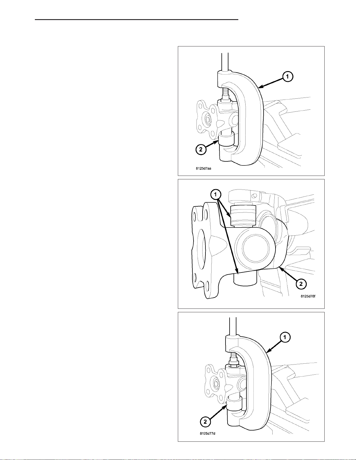
ND PROPELLER SHAFT 3 - 13
DISASSEMBLY - WITH INJECTED RINGS
1. Place shaft yoke in vise.
2. Position U-joint press (1) with receiver (2) on propeller shaft yoke.
3. Pressed U-joint bearing caps (1) out of shaft yoke
(2).
4. Remove lower bearing cap from shaft yoke.
5. Turn shaft over and position press (1) with receiver
(2) on shaft yoke.
Page 97
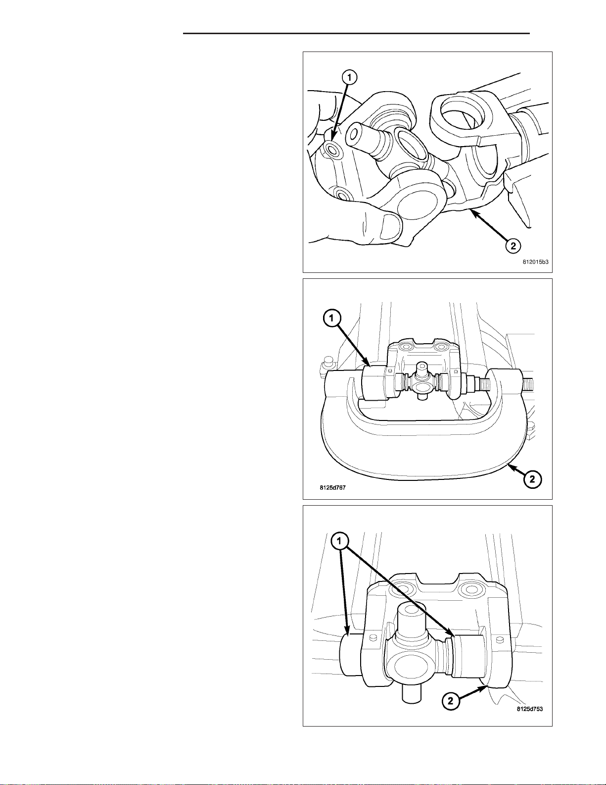
3 - 14 PROPELLER SHAFT ND
6. Press remaining U-joint bearing cap out of shaft
yoke.
7. Remove flange (1) with U-joint out of shaft yoke
(2).
8. Position U-joint press (2) with receiver (1) on
flange.
9. Press U-joint bearing caps (1) out of flange (2).
Page 98
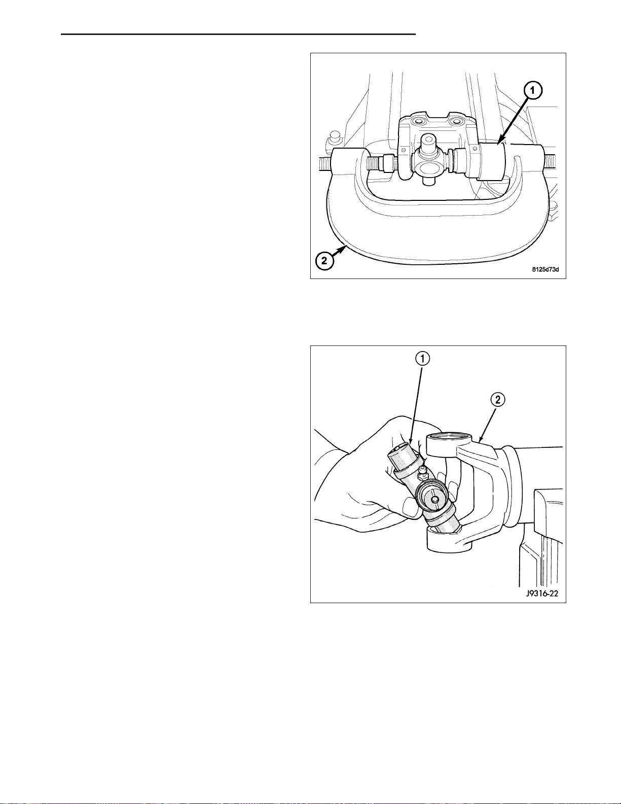
ND PROPELLER SHAFT 3 - 15
10. Remove bearing cap on the outside of the flange.
11. Position U-joint press (2) with receiver (1) on
flange.
12. Press remaining U-joint bearing cap out of flange.
13. Remove U-joint from flange.
ASSEMBLY
ASSEMBLY - WITH SNAP RINGS
NOTE: This procedure describes a propeller shaft
equipped a cardan joint in the tube yoke. For propeller shafts equipped with a companion/slip yoke,
repeat the steps to remove the remaining cardan
joint.
1. Apply (EP) N.L.G.I. Grade 1 or 2 grease to inside
of yoke bores.
2. Position cross (1) in yoke with lube fitting pointing
up, if equipped.
Page 99
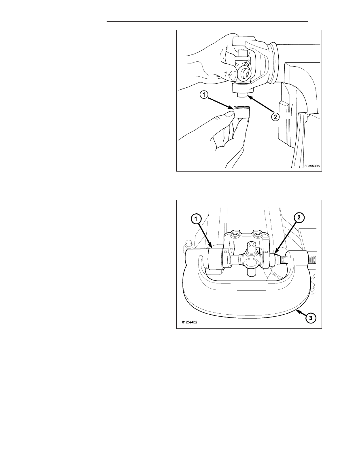
3 - 16 PROPELLER SHAFT ND
3. Place a bearing cap (1) over the cross end (2) and
align cap with yoke bore.
4. Press bearing cap into the yoke bore enough to
clear snap ring groove.
5. Repeat Step 3 and Step 4 to install the opposite
bearing cap.
NOTE: If joint is stiff or binding, strike the yoke
with a soft hammer to seat the needle bearings.
6. Add grease to lube fitting, if equipped.
ASSEMBLY - WITH INJECTED RINGS
NOTE: Replacement joint has internal snap rings.
1. Place joint in flange with one bearing cap.
2. Position press (3) with receiver (1) on flange and
bearing cap (2).
Page 100
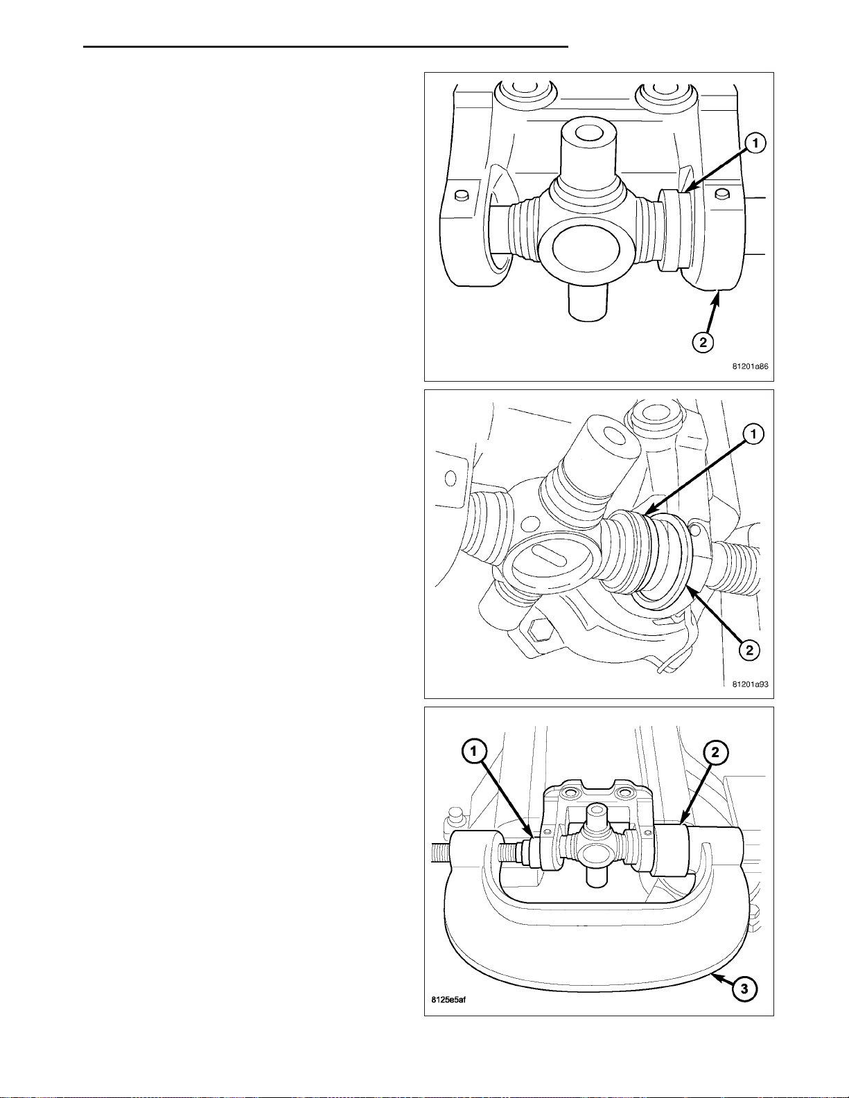
ND PROPELLER SHAFT 3 - 17
3. Press bearing cap until snap ring groove (1) is
through the flange (2).
4. Install snap ring (2) on bearing (1).
5. Position press (3) with receiver (2) on remaining
bearing cap (1) and flange.
 Loading...