

Page 1
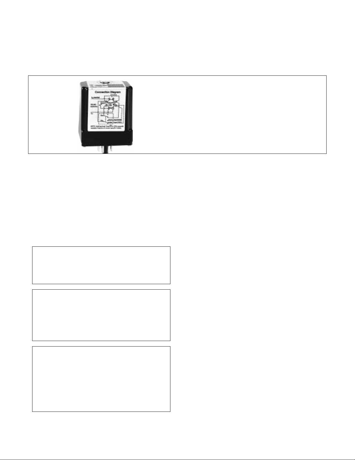
DODGE PLUG IN MODEL 250 POWER SUPPLY
DESCRIPTION:
INSTALLATION MANUAL FOR
Specifications:
Input voltage: 115 VAC 50-60 Hz
Output voltage: 15-100 VDC Nominal
Output current: 0.5 Amp Maximum
Output wattage: 50 Watts Maximum
Dimensions: 2.88” H, 2.38” W, 1.75” D
Installation and Operating Instructions
Model 250 is an octal-base power supply that
converts 115 VAC, 50-60 Hz to a DC voltage. It
provides one fixed 100 VDC output and one
adjustable (15 to 100 VDC) output. The Model 250 is
capable of providing DC operating voltage to 1 or 2
clutches or brakes (each with 50 watts or less power
consumption). If two units are operated with the Model
250 power supply, only one unit should be energized
at a time. Note: Switches Furnished By User.
WARNING
Only qualified electrical personnel familiar with the
construction and operation of this equipment and the
hazards involved should install, adjust, and/or service
this precaution can result in bodily injury.
DANGER
Subsequent steps require rotating parts and/or
electrical circuits to be exposed. Stay clear if unit must
be running or disconnect and lockout or tag power
source if contact must be made. Failure to observe
these precautions could result in severe bodily injury or
loss of life.
DANGER
The user is responsible for conforming to the National
Electrical Code and all other applicable local codes in
respect to wiring practices, grounding, disconnects, and
overcurrent protection. Installation of an approved
disconnecting means in the line side of the controller is of
particular importance. Failure to observe these
precautions could result in severe bodily injury or loss of
life.
1. Be sure power is locked off when wiring a power
supply installation.
2. Use adequate sized wire. No. 18 gauge is
recommend-ed for runs less than 25 feet. No. 16
gauge is recommended for runs 25 feet or longer.
3. The neutral or grounded side of the 115 VAC line
must be connected to terminal 5 on the octal socket.
A voltmeter connected between the neutral line and
line ground will read 0 volts. The hot side of the 115
VAC line must be connected to terminal 1.
Note 1: Connect switches per diagrams. Do not connect
switch for the clutch or brake in coil circuit.
Note 2: Output voltage under load of the power supply
is approximately 100 VDC with 115 VAC input. This is
suitable for clutches and brakes rated 90 VDC.
Note 3: Output voltage without load is about 160 VDC.
Model 250 used with 2 units - adjustable voltage on
unit #1, fixed 100 VDC on unit #2. Connection
Instructions (See Figure 1):
1. All connections are made to terminals on octal
socket.
2. Connect unit #1 to terminals 6 and 8.
3. Connect unit #2 to terminals 3 and 6.
4. Connect side S
(DPDT) switch to terminals 3, 7, and 8; the switch
common must be connected to terminal 7.
5. Connect side S
the switch common must be connected to terminal
6.
6. Connect 115 VAC, 50-60 Hz to terminals 1 and 5.
Warning: The neutral or grounded side must be
connected to terminal 5.
a of a double-pole, double-throw
b of the switch to terminals 6 and 2;
1
Page 2
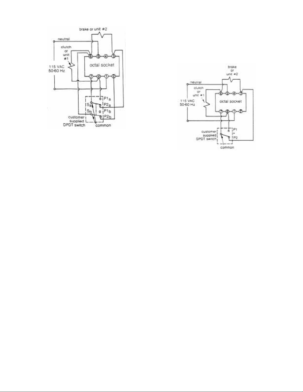
Figure 1
the switch common must be connected to terminal
7. A maintained-contact type SPDT switch should
be used.
5. Connect 115 VAC, 50-60 Hz to terminals 1 and 5.
Warning: The neutral or grounded side must be
connected to terminal 5.
Wiring 2 units (adjustable voltage on unit #1)
Operation:
1. Plug power supply into octal socket.
2. Turn on power source.
3. Voltage adjustments are made by removing plug
button on top of power supply case. This will
expose a screwdriver slotted adjustment. Turn the
adjustment clockwise to increase voltage, or
counterclockwise to decrease voltage. When wired
as described above, the adjusted voltage will be
applied across unit #1.
4. With switch in position P1, unit #1 is energized with
adjusted voltage and unit #2 is de-energized.
5. With switch in position P2 (normally closed), unit
#2 is energized with 100 VDC and unit #1 is deenergized.
6. If unit fails to operate, refer to the Troubleshooting
section.
Note: If unit #1 is energized with fixed 100 VDC, and
unit #2 with adjustable DC voltage, remove lead
between terminal 2 of octal socket and P2
Add lead between terminal 2 of octal socket and P1
switch.
b of switch.
b of
Model 250 used with 2 units – adjustable voltage
on both units.Connection Instructions (See Figure
2):
1. All connections are made to terminals on octal
socket.
2. Connect unit #1 to terminals 6 and 8.
3. Connect unit #2 to terminals 3 and 6.
4. Connect a SPDT switch to terminals 3, 7, and 8;
Figure 2
Wiring 2 units (adjustable voltage on both units)
Operation:
1. Plug power supply into octal socket.
2. Turn on power source.
3. Voltage adjustments are made by removing plug
button on top of power supply case. This will
expose a screwdriver slotted adjustment. Turn the
adjustment clockwise to increase voltage, or
counterclockwise to decrease voltage. When wired
as described above, this same adjusted voltage
will be applied across both unit #1 and unit #2.
4. With switch in position P1, unit #1 is energized with
adjusted voltage and unit #2 is de-energized.
5. With switch in position P2 (normally closed), unit
#2 is energized with adjusted voltage and unit #1 is
de-ener-gized.
6. If unit fails to operate, refer to the Troubleshooting
section.
Model 250 used with 1 unit. Connection
Instructions (See Figure 3):
1. All connections are made to terminals on octal
socket.
2. Connect unit (clutch or brake) to terminals 6 and 8.
3. Connect switch to terminals 7 and 8; the switch
common should be connected to terminal 7. Use a
maintained contact SPDT (shown in Figure 3) or
SPST switch.
4. Connect 115 VAC, 50-60 Hz to terminals 1 and 5.
Warning: The neutral or grounded side must be
connected to terminal 5.
2
Page 3

Figure 4
Fuse Location
Figure 3
Wiring for 1 unit
Operation:
1. Plug power supply into octal socket.
2. Turn on power source.
3. Voltage adjustments are made by removing plug
button on top of power supply case. This will
expose a screwdriver slotted adjustment. Turn the
adjustment clockwise to increase voltage, or
counterclockwise to decrease voltage.
4. With switch in position P1 (or switch closed when
usingSPST) the clutch or brake is energized.
5. With switch in position P2 (or switch open when
usingSPST) the clutch or brake is de-energized.
6. If unit fails to operate, refer to the Troubleshooting
section.
Maintenance
Fuse location and access
Model 250 has an internal fuse. The fuse can be
checked without removing the power supply cover.
First remove the power supply from the octal socket.
An ohmmeter connected between pins 1 and 4 on the
module will read near infinity if the fuse has burned
out. If blown then replace with type 3AG 0.6 amp fuse.
Caution: Do not use slow-blow type fuse.
To replace the fuse, remove four fasteners holding
cover of base plug. Carefully remove the cover. The
fuse is located as shown in Figure 4. Visually check
the fuse. If the fuse is burned out, remove it, and
replace with a new fuse of proper size and type.
Carefully replace the cover and fasteners.
Troubleshooting
If the unit fails to operate or operates in an improper
manner, use the following procedure to identify and
resolve the problem.
1. Check the power source (115 VAC, 50-60 Hz line
voltage). Is it turned on? Using an AC voltmeter,
check the voltage between terminals 1 and 5. The
voltage should be between 110 and 120 VAC.
2. Check actual wiring against the wiring diagram.
Check tosee if voltage adjustment is turned up
high enough to operate clutch or brake.
3. Check fuse. If the fuse is burned out, replace it with
oneof the same type and rating. Review entire
troubleshooting procedure to identify reason for
blown fuse.
4. Disconnect clutch and/or brake from power supply.
Check resistance of clutch and/or brake coils. If
coil is shorted or open it should be replaced.
5. Check the connections between the power supply
and theclutch and/or brake to be operated. If the
connections are loose or the wires damaged or
grounded, correct the problem.
6. If the above corrective actions do not restore
normal oper-ation, the power supply should be
replaced with a new one.
Accessory Requirements
The following accessories are required for installation,
but are not supplied with the Model 250 power supply.
1. Octal socket - DODGE part number 032401.
2. Switch - One switch (SPST, SPDT, or DPDT
depending upon applications). Switch should be
contact type. A minimum of 6A, 120VAC is
recommended.
3. Hook-up wire - as required.
3
Page 4

WARNING: Because of the possible danger to persons(s) or property from accidents which may result from the improper use of products, it is important that
correct procedures be followed. Products must be used in accordance with the engineering information specified in the catalog. Proper installation,
maintenance and operation procedures must be observed. The instructions in the instruction manuals must be followed. Inspections should be made as
necessary to assure safe operation under prevailing conditions. Proper guards and other suitable safety devices or procedures as may be desirable or as may
be specified in safety codes should be provided, and are neither provided by Baldor Electric Company nor are the responsibility of Baldor Elec tric Com pany.
This unit and its associated equipment must be installed, adjusted and maintained by qualified personnel who are familiar with the construction and operation
of all equipment in the system and the potential hazards involved. When risk to persons or property may be involved, a failsafe device must be an inegral part
of the driven equipment beyond the speed reducer output shaft.
www.baldor.com www.ptplace.com www.dodge-pt.com www.reliance.com
Baldor Electric Company Headquarters
P.O. Box 2400, Fort Smith, AR 72902-2400 U.S.A., Ph: (1) 479.648.5792, Fax (1) 479.648.5792, International Fax (1) 479.648.5895
DODGE/Reliance Division
6040 Ponders Court, Greenville, SC 29615-4617 U.S.A., Ph: (1) 864.297.4800, FAX: (1) 864.281.2433
Copyright © 2007 Baldor Electric Company All Rights Reserved. Printed in USA.
04/07
3C-K
This material is not intended to provide operational instructions. Appropriate instruction
manuals and precautions should be studied prior to installation, operation or maintenance
of equipment.
4
 Loading...