


SFRA
Table of contents
 Loading...
Sweep Frequency Response
User Guide
Analyzer (SFRA)
Doble Engineering Company
85 Walnut Street
Watertown, Massachusetts 02472-4037
(USA)
www.doble.com
72A-2570-01 Rev. K 07/2011

LEGAL NOTICE
Warranty
Equipment Limited
Warranty
Doble Engineering Company (Doble) warrants the products that it
manufactures to be free from defects in material and workmanship for a period
of one year from the date shipped from the factory.
During the one-year warranty period, Doble will repair or replace, at its
option, any defective products or components thereof at no additional charge,
provided that the product or component is returned, shipping prepaid, to
Doble. The Purchaser is responsible for insuring any product or component so
returned and assumes the risk of loss during shipment. All replaced products
and components become the property of Doble.
THIS LIMITED WARRANTY DOES NOT EXTEND TO ANY PRODUCTS
WHICH HAVE BEEN DAMAGED AS A RESULT OF ACCIDENT,
MISUSE, ABUSE, OR AS A RESULT OF MODIFICATION BY ANYONE
OTHER THAN DOBLE OR AN AUTHORIZED DOBLE
REPRESENTATIVE.
EXCEPT AS EXPRESSLY SET FORTH ABOVE, NO OTHER
WARRANTIES, EXPRESSED OR IMPLIED, ARE MADE WITH
RESPECT TO THE PRODUCT INCLUDING, BUT NOT LIMITED TO,
ANY IMPLIED WARRANTIES OF MERCHANTABILITY AND FITNESS
FOR A PARTICULAR PURPOSE. IN THE EVENT THE PRODUCT IS
NOT FREE FROM DEFECTS AS WARRANTED HEREIN, THE
PURCHASER’S SOLE REMEDY SHALL BE REPAIR OR
REPLACEMENT AS PROVIDED ABOVE. UNDER NO
CIRCUMST ANCES WILL DOBLE BE LIABLE TO THE PURCHASER OR
ANY USER FOR ANY DAMAGES, CAUSED BY OR ARISING OUT OF
THE USE OF OR INABILITY TO USE THIS PRODUCT, INCLUDING
WITHOUT LIMITATION, PERSONAL INJURY OR PROPERTY
DAMAGE, ANY INCIDENTAL OR CONSEQUENTIAL DAMAGES,
EXPENSES, LOST PROFITS, LOST SAVINGS, OR OTHER DAMAGES.
Software Limited
Warranty
Doble warrants the disks on which the software product is furnished to be free
from defects in materials and workmanship under normal use for a period of
one hundred and twenty (120) days from the date of shipment from Doble.
Purchaser’s exclusive remedy shall be the replacement of any disks not
meeting Doble’s Software Limited Warranty which have been returned to
Doble within the warranty period.
This warranty gives the purchaser specific legal rights and the purchaser may
also have other rights which vary from state to state.

EXCEPT AS DETAILED ABOVE AND TO THE EXTENT ALLOWED BY
ANY APPLICABLE STATE AND FEDERAL LAWS: THIS SOFTWARE
PRODUCT IS PROVIDED “AS IS” WITHOUT WARRANTY OF ANY
KIND, EITHER EXPRESSED OR IMPLIED, INCLUDING, BUT NOT
LIMITED TO, THE IMPLIED WARRANTIES OF MERCHANTABILITY
AND FITNESS FOR A PARTICULAR PURPOSE. THE ENTIRE RISK AS
TO THE QUALITY AND PERFORMANCE OF THIS SOFTWARE
PRODUCT IS WITH PURCHASER SHOULD THE PRODUCT PROVE
DEFECTIVE. PURCHASER (AND NOT DOBLE OR AN AUTHORIZED
DEALER) ASSUMES ALL LIABILITY ASSOCIATED WITH THE
SOFTWARE AND THE ENTIRE COST OF ALL NECESSARY
SERVICING, REPAIR, OR CORRECTION.
Limitations of
Remedies
If Doble notifies Purchaser that is unable to deliver replacement disks which
are free from defects in materials and workmanship, Purchaser may terminate
this agreement. By returning the software product and all copies thereof in any
form and affirming compliance with this requirement in writing, Doble will
refund the purchase price.
TO THE EXTENT ALLOWED BY ANY APPLICABLE STATE AND
FEDERAL LAWS, DOBLE EXPRESSLY DISCLAIMS ALL
WARRANTIES NOT STATED HEREIN. IN NO EVENT WILL DOBLE BE
LIABLE TO PURCHASER FOR ANY DAMAGES, INCLUDING ANY
LOST PROFITS, LOST SAVINGS OR OTHER INCIDENTAL OR
CONSEQUENTIAL DAMAGES ARISING OUT OF THE USE OR
INABILITY TO USE ANY SOFTWARE OR PRODUCT, OR FOR ANY
TECHNICAL OR EDITORIAL ERRORS OF COMMISSION OR
OMISSION, EVEN IF DOBLE OR AN AUTHORIZED DEALER HAS
BEEN ADVISED OF THE POSSIBILITY OF SUCH DAMAGES, OR FOR
ANY CLAIM BY ANY OTHER PARTY.
Maintenance For Equipment Maintenance, contact:
Customer Service Manager
Doble Engineering Company
85 Walnut Street
Watertown, MA02472 (USA)
Telephone: 617-923-2921
FAX: 617-926-0528
Email: customerservice@doble.com
Web: www.doble.com

Government
Restricted Rights
Legend
Use, Duplication, or Disclosure by the U.S. Government is subject to
restrictions as set forth in subparagraphs (c)(1) and (c)(2) of the Commercial
Computer Software - Restricted Rights Clause at FAR 52.227-19.
Intellectual
Property Notice
This Manual is solely the property of the Doble Engineering Company
(Doble) and is provided for the exclusive use of Doble clients under
contractual agreement for Doble test equipment and services.
This Manual is protected by copyright, all rights reserved. No part of this book
shall be reproduced, stored in a retrieval system, or transmitted by any means,
electronic, mechanical, photocopying, recording, or otherwise without written
permission from the Doble Engineering Company.
Doble and the Doble logo are trademarks of Doble Engineering Company.
Microsoft, Windows, Windows XP, Vista, and Windows 7 are registered
trademarks of Microsoft Corporation in the United States and/or other
countries.
Copyright ©1999-2011
By Doble Engineering Company
All Rights Reserved

Content s
List of Figures .............................................................................................ix
List of Tables .............................................................................................xiii
Preface .......................................................................................................xv
1. Introduction ..........................................................................................1-1
M5200, M5300, and M5400 SFRA Instruments..........................................................................1-1
Hardware Accessories ..................................................................................................................1-3
Software........................................................................................................................................1-4
PC Requirements..........................................................................................................................1-4
2. Safety ...................................................................................................2-1
Overview ......................................................................................................................................2-1
General Rules ...............................................................................................................................2-1
Grounding Requirements..............................................................................................................2-2
Personnel Safety Practices............................................................................................................ 2-3
3. Setting Up and Running a Test ............................................................3-1
Measurement Types......................................................................................................................3-1
Open Circuit...........................................................................................................................3-1
Short Circuit........................................................................................................................... 3-1
Step 1: Set Up and Run a Shorted-lead Test ................................................................................ 3-2
Connect the Cable and Leads and Run SFRA 5.2..................................................................3-2
Create a Transformer Listing and Associate a Test Template with It....................................3-4
Run the Shorted-lead Test......................................................................................................3-8
Step 2: Ground the Transformer.................................................................................................3-12
Step 3: Prepare the Transformer for Testing..............................................................................3-14
72A-2570-01 Rev. K 07/2011 v

Sweep Frequency Response Analyzer (SFRA) User Guide
Step 4: Select and Run a Test.....................................................................................................3-15
Requirements for This Test..................................................................................................3-15
Associate the Transformer with a Test Template.................................................................3-15
SFRA Test Procedure...........................................................................................................3 -18
Self-Test Error and Warning Messages................................................................................3-22
Troubleshooting Test Results...............................................................................................3-24
Monitoring Waveforms..................................................................................................3-24
Diagnosing Open-Circuit Response...............................................................................3-25
Sample Test Results....................................................................................................................3-25
Three Responses for One Transformer.................................................................................3-25
HV Wye (Star) Response .....................................................................................................3-27
Short-Circuit Test Response.................................................................................................3-27
Repeat Results for One Phase at Different Times................................................................3-29
Results Showing a Shorted Turn..........................................................................................3-29
Confirming the Ethernet Connection....................................................................................3-30
4. Managing Tests and Templates ...........................................................4-1
Introduction...................................................................................................................................4-1
Opening the Template Editor........................................................................................................4-1
Creating a New Test Template .....................................................................................................4-2
Editing or Deleting a Template.....................................................................................................4-3
Adding, Editing, or Deleting Tests in a Template........................................................................4-3
Creating a New Test Setting...................................................................................................4-4
Editing or Deleting a Test Setting..........................................................................................4-4
5. Managing Data and Generating Reports ..............................................5-1
Managing Location Information...................................................................................................5-1
Adding or Deleting SFRA Instrument Information......................................................................5-3
Adding or Deleting Organization Information .............................................................................5-4
Managing Transformer Information.............................................................................................5-5
Entering a Transformer into the SFRA Database...................................................................5-5
Editing or Deleting Transformer Data....................................................................................5-6
Cloning a Transformer ...........................................................................................................5-6
Importing and Exporting Transformer Files...........................................................................5-7
Managing Tap Changer Data........................................................................................................5-7
vi 72A-2570-01 Rev. K 07/2011

Contents
Managing Results Data................................................................................................................. 5-8
Default Data Locations ..........................................................................................................5-8
Selecting a Data Source .........................................................................................................5-9
Export Selected Results to .CSV Files.................................................................................5-10
Import Location and Transformer from Results Files..........................................................5-11
Saving and Deleting Traces .................................................................................................5-11
Importing 1.x and 2.x M5100 SFRA Files...........................................................................5-12
Transferring Data between Machines or PCs.......................................................................5-12
Settings Files........................................................................................................................5-12
Merging Settings Files ......................................................................................................... 5-14
Reports ................................................................................................................................. 5-16
A. Software Overview ...............................................................................A-1
Installing SFRA 5.2..................................................................................................................... A-1
Manually Install the USB Driver.................................................................................................A-5
Where to Find the Driver ...................................................................................................... A-5
Remove Previously Installed USB Drivers...........................................................................A-5
Install the Driver ...................................................................................................................A-5
SFRA 5.2 Software Overview..................................................................................................... A-6
File Menu .............................................................................................................................. A-6
Edit Menu.............................................................................................................................. A-6
Test Init Menu....................................................................................................................... A-7
Graph Menu ..........................................................................................................................A-7
Help....................................................................................................................................... A-9
Apparatus/Test and Legend Panes.............................................................................................A-10
Apparatus and Test Pane..................................................................................................... A-10
Legend Pane........................................................................................................................ A-10
72A-2570-01 Rev. K 07/2011 vii

Sweep Frequency Response Analyzer (SFRA) User Guide
Tab Divisions in SFRA..............................................................................................................A-11
Data Manager Tab...............................................................................................................A-11
Magnitude Tab.....................................................................................................................A-12
Phase Tab.............................................................................................................................A-13
Impedance Tab ....................................................................................................................A-14
Sub-Band Tab......................................................................................................................A-15
Waveform Tab.....................................................................................................................A-16
Analysis Tab........................................................................................................................A-17
Tabulation Tab.....................................................................................................................A-18
Apparatus Tab .....................................................................................................................A-19
B. Test Templates ....................................................................................B-1
Introduction.................................................................................................................................. B-1
Notes About the Test Templates..................................................................................................B-1
Two-Winding Transformers........................................................................................................B-2
Autotransformers.........................................................................................................................B-3
Three-Winding Transformers......................................................................................................B-4
C. Theory of Operation.............................................................................C-1
Transformer Damage and SFRA Testing .................................................................................... C-1
How SFRA Identifies Damage to Transformers .........................................................................C-2
Test Cable Lengths ...................................................................................................................... C-4
Transformer ................................................................................................................................. C-5
D. Repairs and Replacement Parts..........................................................D-1
Replacing a Fuse..........................................................................................................................D-1
Repairs.........................................................................................................................................D-3
Replacement Parts .......................................................................................................................D-3
M5200 and M5400................................................................................................................D-3
M5300....................................................................................................................................D-5
E. M5200/M5300/M5400 Technical Specifications...................................E-1
Instrument Specifications .............................................................................................................E-1
Lead Specifications.......................................................................................................................E-3
PC Requirements ..........................................................................................................................E-4
viii 72A-2570-01 Rev. K 07/2011

List of Figures
Figure 1.1 M5200, M5300, and M5400 Instruments............................................................. 1-2
Figure 2.1 Connecting Safety Ground to Transformer........................................................... 2-2
Figure 3.1 Cable and Lead Connections to the SFRA Instrument......................................... 3-2
Figure 3.2 Connect to Instrument Message............................................................................ 3-3
Figure 3.3 Select Instrument Window.................................................................................... 3-3
Figure 3.4 Data Manager Tab on Main Window ................................................................... 3-4
Figure 3.5 Edit Apparatus Option on Edit Menu ................................................................... 3-5
Figure 3.6 Test Equipment Editor.......................................................................................... 3-5
Figure 3.7 Transformer Tab of Transformer Editor Window ............................................... 3-6
Figure 3.8 New Serial Number Listing .................................................................................. 3-6
Figure 3.9 Test Templates Tab of Transformer Editor Window............................................ 3-7
Figure 3.10 Template Editor Window...................................................................................... 3-7
Figure 3.11 Apparatus Selection Window................................................................................ 3-8
Figure 3.12 Location of Start Test Button ................................................................................ 3-8
Figure 3.13 Test Details Window............................................................................................. 3-9
Figure 3.14 Cable Connections for Shorted-lead Test ............................................................. 3-9
Figure 3.15 Shorted-lead Test in Progress ............................................................................. 3-10
Figure 3.16 Correct Shorted-lead Response........................................................................... 3-11
Figure 3.17 Open-Circuit Lead Response.............................................................................. 3-11
Figure 3.18 De-energized and Disconnected Transformer.................................................... 3-12
Figure 3.19 Grounded Transformer........................................................................................ 3-12
Figure 3.20 Removed Isophase or GIS Link.......................................................................... 3-13
Figure 3.21 Added Temporary Static-Discharge Grounds..................................................... 3-13
Figure 3.22 Connected SFRA Leads...................................................................................... 3-13
Figure 3.23 Removed Temporary Static-Discharge Grounds................................................ 3-14
Figure 3.24 Edit Apparatus Option on Edit Menu ................................................................. 3-15
Figure 3.25 Test Equipment Editor........................................................................................ 3-16
Figure 3.26 Transformer Tab of Transformer Editor Window ............................................. 3-16
Figure 3.27 Test Templates Tab of Transformer Editor Window.......................................... 3-17
Figure 3.28 Template Editor Window.................................................................................... 3-17
Figure 3.29 Apparatus Selection Window.............................................................................. 3-18
Figure 3.30 Location of Select Test Button............................................................................ 3-19
72A-2570-01 Rev. K 07/2011 ix

Sweep Frequency Response Analyzer (SFRA) User Guide
Figure 3.31 Test Selection Window ....................................................................................... 3-19
Figure 3.32 Location of Start Test Button.............................................................................. 3-20
Figure 3.33 Test Details Window........................................................................................... 3-20
Figure 3.34 Nonstandard Test Warning ................................................................................. 3-21
Figure 3.35 Test Details Dialog Box with Advanced Test Protocol ...................................... 3-21
Figure 3.36 Alert 952.............................................................................................................. 3-22
Figure 3.37 Error 953 ............................................................................................................. 3-23
Figure 3.38 Test in Progress................................................................................................... 3-24
Figure 3.39 Typical Open-Circuit Trace ................................................................................ 3-25
Figure 3.40 Responses for One Phase of a Transformer HV Delta Trace.............................. 3-26
Figure 3.41 HV Delta Winding Traces................................................................................... 3-26
Figure 3.42 HV Wye Winding Trace ..................................................................................... 3-27
Figure 3.43 Short-Circuit Test Trace...................................................................................... 3-28
Figure 3.44 Short Circuit Trace – Detail................................................................................ 3-28
Figure 3.45 Repeat Results for One Phase ............................................................................. 3-29
Figure 3.46 Shorted Turn on One Winding............................................................................ 3-30
Figure 3.47 Start Menu........................................................................................................... 3-30
Figure 3.48 Command Window Displaying IP Address........................................................ 3-31
Figure 4.1 Template Editor..................................................................................................... 4-2
Figure 4.2 Test Setting Editor................................................................................................. 4-3
Figure 5.1 Test Equipment Editor .......................................................................................... 5-2
Figure 5.2 Entering a New Location ...................................................................................... 5-2
Figure 5.3 Entering a New Serial Number ............................................................................. 5-3
Figure 5.4 Entering a New Organization................................................................................ 5-4
Figure 5.5 Transformer Tab of Transformer Editor Window ................................................ 5-5
Figure 5.6 Edit Serial Number Dialog Box............................................................................ 5-6
Figure 5.7 LTC/DETC Tab of Transformer Editor Window ................................................. 5-8
Figure 5.8 Sweep Frequency Response Analyzer Settings Dialog Box................................. 5-9
Figure 5.9 Browse for Folder Dialog Box.............................................................................. 5-9
Figure 5.10 Files Converted Dialog Box................................................................................ 5-11
Figure 5.11 Simplified XML Transformer Settings File........................................................ 5-13
Figure 5.12 Transformer Settings File — User A .................................................................. 5-14
Figure 5.13 Transformer Settings File — User B .................................................................. 5-15
Figure 5.14 TransformerNameplate Section of User B’s Settings File.................................. 5-16
Figure 5.15 Report Designer Window.................................................................................... 5-17
Figure A.1 Welcome Window of Setup Wizard .................................................................... A-2
Figure A.2 Select Installation Folder Window ....................................................................... A-2
Figure A.3 Confirm Installation Window .............................................................................. A-3
x 72A-2570-01 Rev. K 07/2011

List of Figures
Figure A.4 Progress Bar in Installation Window................................................................... A-3
Figure A.5 Identifying an M5300 .......................................................................................... A-4
Figure A.6 Select Default Template Window........................................................................ A-4
Figure A.7 Plot Property Dialog Box................................................................................... A-10
Figure A.8 Data Manager Tab.............................................................................................. A-11
Figure A.9 Magnitude Tab................................................................................................... A-12
Figure A.10 Status Bar........................................................................................................... A-12
Figure A.11 Phase Tab........................................................................................................... A-13
Figure A.12 Status Bar........................................................................................................... A-13
Figure A.13 Impedance Tab................................................................................................... A-14
Figure A.14 Status Bar........................................................................................................... A-14
Figure A.15 Sub-Band Tab .................................................................................................... A-15
Figure A.16 Waveform Tab................................................................................................... A-16
Figure A.17 Analysis Tab ...................................................................................................... A-17
Figure A.18 Tabulation Tab................................................................................................... A-18
Figure A.19 Apparatus Tab.................................................................................................... A-19
Figure D.1 Location of Fuses on M5400 ............................................................................... D-1
Figure D.2 Blade in Top of Fuse Cover................................................................................. D-2
Figure D.3 Open Fuse Cover with Fuses in Place.................................................................. D-2
72A-2570-01 Rev. K 07/2011 xi

Sweep Frequency Response Analyzer (SFRA) User Guide
xii 72A-2570-01 Rev. K 07/2011

List of Tables
Table 1.1 M5200, M5300, and M5400 Instruments .............................................................1-2
Table 1.2 Accessories for the SFRA Instruments ................................................................. 1-3
Table A.1 File Menu Options ................................................................................................A-6
Table A.2 Edit Menu Options ................................................................................................ A-6
Table A.3 Test Init Menu Options .........................................................................................A-7
Table A.4 Graph Menu Options ............................................................................................A-7
Table A.5 Help Menu Options .............................................................................................. A-9
Table B.1 Two-Winding Transformers — 9 Tests ................................................................ B-2
Table B.2 Autotransformer without Tertiary or with Buried Tertiary — 9 Tests ................. B-3
Table B.3 Autotransformer With Tertiary — 18 Tests ......................................................... B-3
Table B.4 Three-Winding Transformer Table – 18 Tests (Part 1) ........................................ B-4
Table B.5 Three-Winding Transformer Table – 18 Tests (Part 2) ........................................ B-5
Table D.1 M5200 and M5400 Cable and Adapter Parts List ................................................ D-3
Table D.2 M5200 and M5400 Additional Components ........................................................D-4
Table D.3 M5300 Cable and Adapter Shipping/Replacement List .......................................D-5
Table D.4 M5300 Additional Components ...........................................................................D-5
Table E.1 Instrument Specifications ......................................................................................E-1
Table E.2 Test Lead Specifications ........................................................................................E-3
Table E.3 PC Requirements ...................................................................................................E-4
72A-2570-01 Rev. K 07/2011 xiii

Sweep Frequency Response Analyzer (SFRA) User Guide
xiv 72A-2570-01 Rev. K 07/2011

Preface
The Sweep Frequency Response Analyzer User Guide explains how to install,
configure, and operate Doble’ s M5200, M5 300, and M5400 Sweep Frequency
Response Analyzer instruments.
Who Should Read This Guide
This guide is intended for engineers and field testers who work with an
M5200, M5300, or M5400 Sweep Frequency Response Analyzer. It is
assumed that the reader is familiar with professional standards and safety
practices.
Document Conventions
Typefaces
This document uses special typefaces to indicate particular kinds of
information:
Notes and Warnings
This document uses icons to draw your attention to information of special
importance, as follows.
Notes
72A-2570-01 Rev. K 07/2011 xv
• Bold Arial type identifies software controls and text you must enter:
Example: Type in
• Monospaced type identifies text that is displayed in the user interface,
such as an error message or prompt:
Uploading test results.
NOTE! Notes provide supplemental information that may apply to only
some circumstances.
1500 ms.
Sweep Frequency Response Analyzer (SFRA) User Guide
Cautions
CAUTION! Cautions provide information that prevents damage to
hardware or data.
Warnings
WARNING! Warnings tell you how to prevent injury or death to anyone
near the test set or high-voltage equipment.
xvi 72A-2570-01 Rev. K 07/2011

1. Introduction
This chapter describes the SFRA instrument hardware and software and
introduces SFRA testing. It contains the following sections:
• “M5200, M5300, and M5400 SFRA Instruments” on page 1-1
• “Hardware Accessories” on page 1-3
• “Software” on page 1-4
• “PC Requirements” on page 1-4
M5200, M5300, and M5400 SFRA Instruments
Sweep Frequency Response Analysis (SFRA) testing is a nonintrusive way to
identify mechanical changes inside a transformer. Changes in the internal
configuration produce different frequency responses that indicate a range of
failure modes. Performed in the field, without teardown or draining of oil,
SFRA testing provides accurate and repeatable measurements.
The M5200, M5300, and M5400 Sweep Frequency Response Analyzers
measure and record the frequency-response characteristics of transformer
windings. Each unit consists of a robust molded shell housing a field
controller and instrumentation module, an excitation source, and a
measurement module. Table 1.1 describes the three SFRA instruments.
72A-2570-01 Rev. K 07/2011 1-1
Sweep Frequency Response Analyzer (SFRA) User Guide
Table 1.1 M5200, M5300, and M5400 Instruments
Name Description Image
M5200 Requires an external
laptop. Testing functions
are identical to those of
the M5300 and M5400.
M5300 Has a built-in laptop,
keyboard, and display.
Testing functions are
identical to those of the
M5200 and M5400.
M5400 A compact version of the
M5200 that requires an
external laptop. Testing
functions are identical to
those of the M5200 and
M5300.
Figure 1.1 M5200, M5300, and M5400 Instruments
1-2 72A-2570-01 Rev. K 07/2011
Hardware Accessories
Table 1.2 describes the standard hardware accessories that come with the
M520, M5300, and M5400. It also lists an optional test lead.
Table 1.2 Accessories for the SFRA Instruments
Test Leads
1. Introduction
Item Description Part No.
Standard lead Length: 18 m/60 ft
Ground: 3.6 m/12 ft
Application: 362 kV
Optional lead Length: 30 m/100 ft
Ground: 5.4 m/18 ft
Application: > 362 kV
Grounds
Safety ground Length: 9 m/30 ft 02C-0019-01
05B-0659-04
05B-0659-07
Ground lead 1.5 m/5 ft 02B-0026-02
72A-2570-01 Rev. K 07/2011 1-3
Sweep Frequency Response Analyzer (SFRA) User Guide
Table 1.2 Accessories for the SFRA Instruments
Item Description Part No.
Communication Cables
USB
No picture available.
Ethernet crossover
No picture available.
Other Hardware
Clamps Two plain copper
Has a square and an
oblong connector.
Has two Ethernet
connectors. Required
for SFRA. SFRA does
not work with a
standard network
cable without a
crossover adapter.
clamps. These clamps
connect to larger
bushing studs or
terminals that the
normal connectors do
not fit. The standard
test cables then clip to
these large clamps.
181-0585
181-0646
212-0444
Software
The M5200 and M5400 are controlled by a user-supplied laptop computer
running Doble SFRA software (supplied with the instrument). The M5300
comes with a built-in PC, laptop keyboard, and preinstalled Doble SFRA
software.
PC Requirements
To see the minimum requirements for the PC used with the M5200 or M5400,
please go to “PC Requirements” on page E-4.
1-4 72A-2570-01 Rev. K 07/2011

2. Safety
Overview
This chapter reviews the standards and procedures you need to follow to use
the SFRA instrument safely. It contains the following sections:
• “Overview” on page 2-1
• “General Rules” on page 2-1
• “Grounding Requirements” on page 2-2
• “Personnel Safety Practices” on page 2-3
Safety cannot be over-emphasized when working on or around high-voltage
electrical apparatus. Companies that generate, transmit, distribute, or use
high-voltage electricity should, and do, have precise rules for safe practices
and procedures. These practices are important for personnel whose working
responsibilities involve testing and maintaining high-voltage apparatus and its
associated lines, cables, conductors, and accessories.
General Rules
72A-2570-01 Rev. K 07/2011 2-1
1. The transformer under test should be completely de-energized and isolated
from the power system before performing any tests using an M5000-series
SFRA instrument.
2. The method of testing a high-voltage apparatus (transformer) involves
exciting the apparatus with the SFRA instrument. Take care to avoid
contact with the apparatus being tested, its associated bushings and
conductors, and the SFRA instrument’s cables and connectors.
3. The test crew must make a visual check to ensure that the apparatus
terminals are isolated from the power system. Because the apparatus under
test may fail, take precautions (such as barriers or entrance restrictions to
the test area) to avoid harm in case of violent failure.
Sweep Frequency Response Analyzer (SFRA) User Guide
4. All of your company rules for safe practice in testing must be strictly
conformed to, including all practices for tagging and isolating apparatus
during testing and maintenance work. State, local, and federal regulations,
e.g., OSHA, may also apply.
Company rules and government regulations take precedence over Doble
recommendations.
Personal protective equipment suitable for electrical testing of
transformers is recommended.
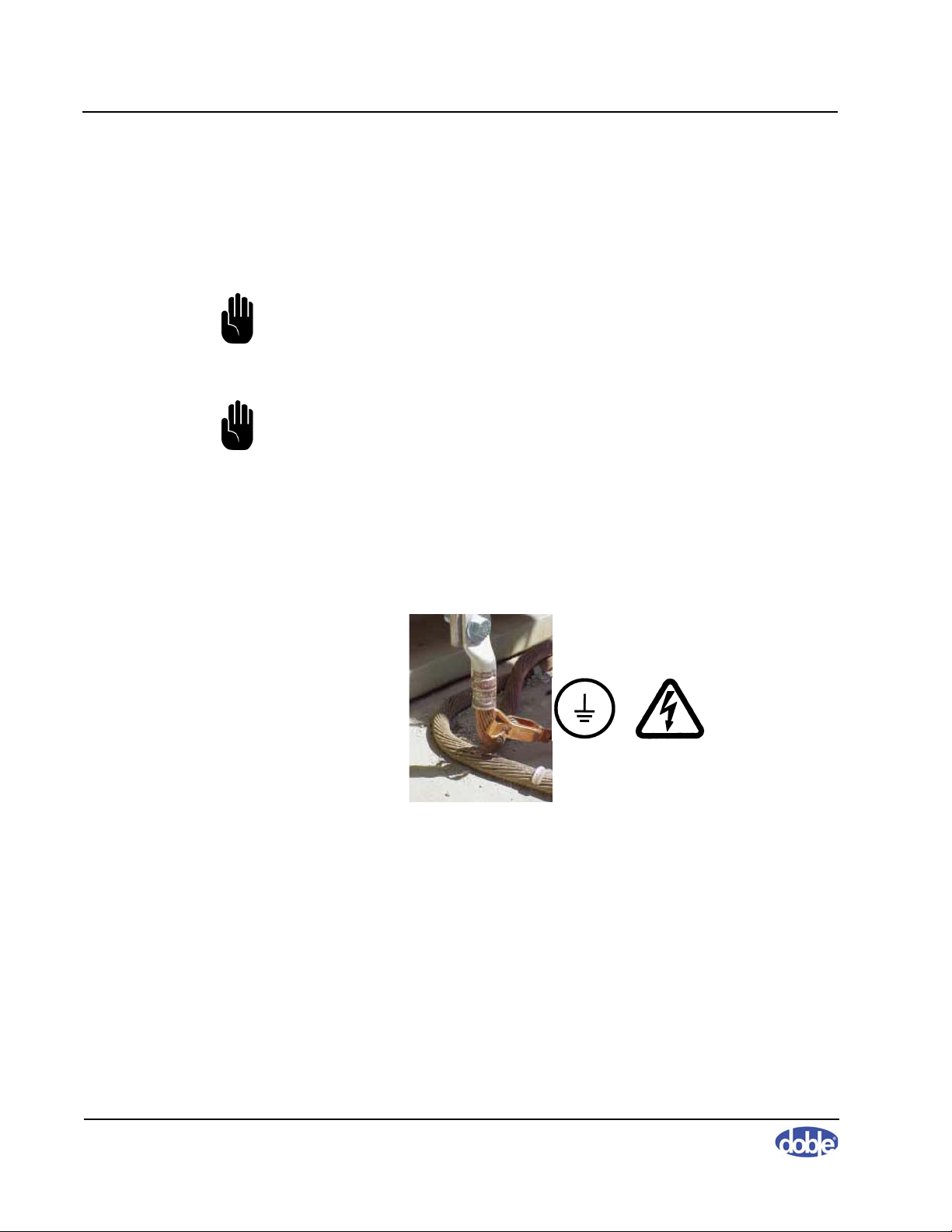
Grounding Requirements
The apparatus under test, its tank or housing, and the SFRA instrument must
be solidly and commonly grounded or earthed. This also applies to any mobile
equipment being tested. Figure 2.1 shows a sample safety ground connection.
Figure 2.1 Connecting Safety Ground to Transformer
For detailed instructions on grounding the SFRA instrument, go to
Ground the Transformer” on page 3-12
.
“Step 2:
2-2 72A-2570-01 Rev. K 07/2011

Personnel Safety Practices
Make sure that test personnel follow these recommendations:
1. A pretest meeting is recommended. Frequently, other crews will be
working on non-test-related tasks in close proximity to equipment being
tested. The pretest meeting should include all personnel who will be
working in proximity to the area where testing will be performed. In this
meeting, review with crew members the tests to be performed, apparatus,
voltage test levels involved, potential hazards, and individual assignments.
Test personnel need to remain aware of the work activity taking place
around them and alert to the possibility that non-test personnel may enter
the test area.
2. Agree on a consistent and uniform set of signals, both visual and verbal.
All crew members should follow them during testing.
3. While making the various types of connections involved in the tests, it
may be necessary for personnel to climb up on the apparatus, but no one
should remain on the apparatus during the test itself.
2. Safety
72A-2570-01 Rev. K 07/2011 2-3

Sweep Frequency Response Analyzer (SFRA) User Guide
2-4 72A-2570-01 Rev. K 07/2011

3. Setting Up and Running a Test
This chapter describes how to set up hardware and configure software for
testing and run the test. It also describes typical test results. This chapter
contains the following sections:
• “Measurement Types” on page 3-1
• “Step 1: Set Up and Run a Shorted-lead Test” on page 3-2
• “Step 2: Ground the Transformer” on page 3-12
• “Step 3: Prepare the Transformer for Testing” on page 3-14
• “Step 4: Select and Run a Test” on page 3-15
• “Sample Test Results” on page 3-25
Measurement Types
Open Circuit
An open-circuit measurement is made from one end of a winding to another,
with all other winding terminals floating. For a delta winding, connections
would be H1 to H3, for example. For a star (wye) winding, measurements are
taken from HV terminals to neutral, such as X1 to X0.
Short Circuit
72A-2570-01 Rev. K 07/2011 3-1
A short-circuit measurement is made with the same SFRA test lead
connections as an open-circuit measurement, but with the difference that
another winding is short- circuited. To ensure repeatability, Doble
recommends that the three voltage terminals on the shorted winding be shorted
together . This would mean, for example, shorting X1 to X2, X2 to X3, and X3
to X1. This ensures that all three phases are similarly shorted, ensuring a
consistent impedance. Do not include in the shorting process any neutral
connections available for the shorted winding.
Sweep Frequency Response Analyzer (SFRA) User Guide
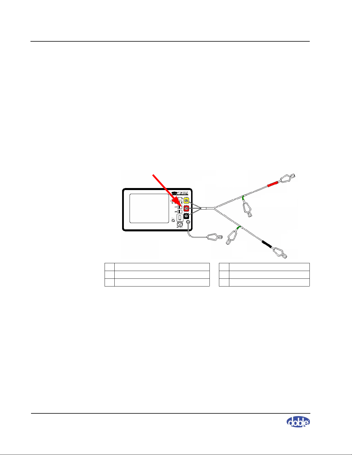
1 BNC yellow, red, and black connectors 4 Green reference ground 2 of 2
2 Instrument ground 5 Red source lead
3 Green reference ground 1 of 2 6 Black measurement lead
1
2
4
3
5
6
Step 1: Set Up and Run a Shorted-lead Test
This section describes how to connect the cables to the SFRA instrument and
perform a basic shorted-lead test. Do not omit this test. If a cable or cable
connection is bad, this test will save you hours of wasted effort.
Connect the Cable and Leads and Run SFRA 5.2
To connect the ground reference cable and test leads and run SFRA:
1. Follow Figure 3.1 to connect the reference ground and test leads to the
instrument. This figure shows an M5300, but the connections are correct
for all three instruments.
Figure 3.1 Cable and Lead Connections to the SFRA Instrument
If you are using an:
• M5200 or M5400—Go to step 2.
• M5300—Power up the M5300 and go to “Create a Transformer
2. Power up the PC. Run the SFRA program by double-clicking the icon or
selecting
Listing and Associate a Test Template with It” on page 3-4.
StartAll ProgramsDoble EngineeringSFRA.
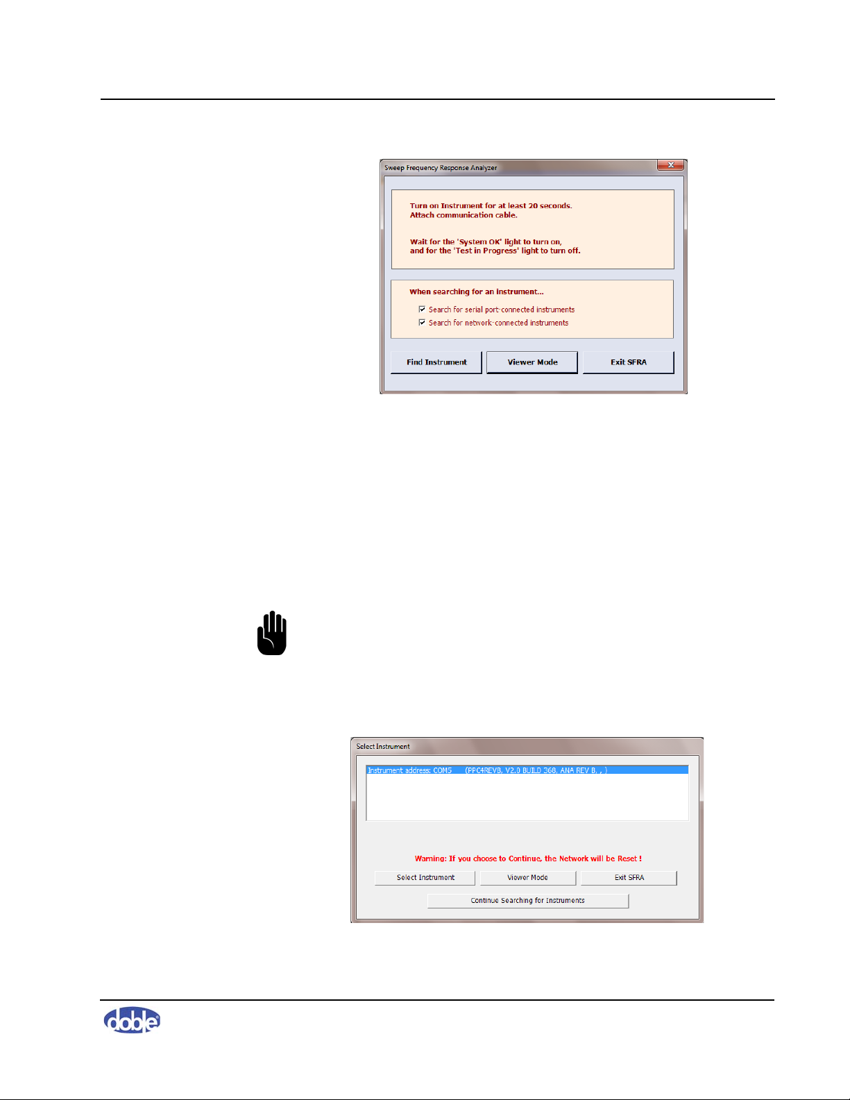
The main SFRA window opens and displays the
Instrument
message (Figure 3.2 on page 3-3).
3-2 72A-2570-01 Rev. K 07/2011
Connect to
3. Setting Up and Running a Test
Figure 3.2 Connect to Instrument Message
3. Turn on the SFRA instrument and wait 20 seconds. During this time:
a. The power light comes on.
b. The Test in Progress and System OK indicator lights come on.
c. The Test in Progress and System OK indicator lights go out.
d. The System OK indicator light comes on and remains lighted.
4. Attach the Ethernet or USB cable to the instrument and the PC.
NOTE: You can shorten the search time by deselecting any
communication type that is not in use.
5. Click the
Find Instrument button shown in Figure 3.2.
The Select Instrument window lists all connected instruments (Figure 3.3).
Figure 3.3 Select Instrument Window
72A-2570-01 Rev. K 07/2011 3-3
Sweep Frequency Response Analyzer (SFRA) User Guide
If no instrument is listed:
• Check the connection between the instrument and the PC.
• Check the antivirus or firewall software for problems.
• If your instrument is connected to the PC through an Ethernet cable,
confirm that the PC can see the instrument. To do this, see
“Confirming the Ethernet Connection” on page 3-30.
6. Click
7. Highlight the instrument desired and click
Continue Searching for Instruments.
Select Instrument.
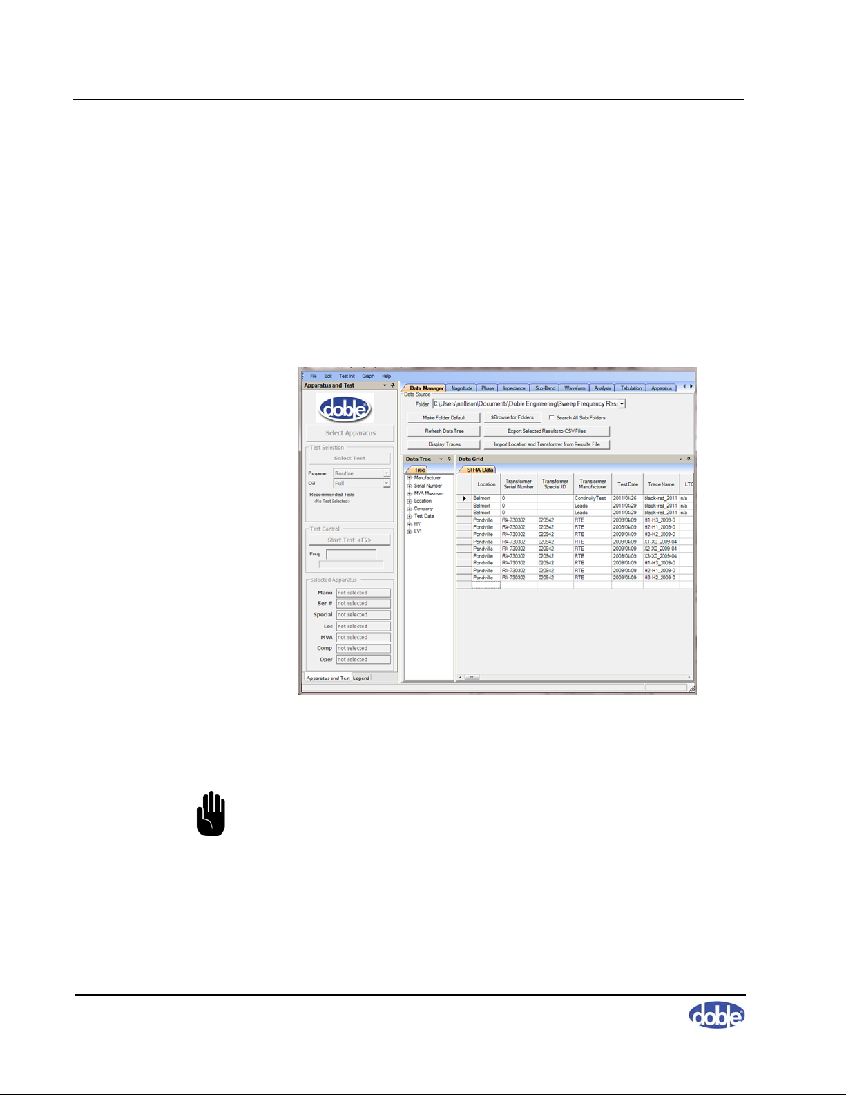
The SFRA window displays the Data Manager tab (Figure 3.4).
Figure 3.4 Data Manager Tab on Main Window
Create a Transformer Listing and Associate a Test Template with It
NOTE: If the shorted-lead test has already been set up in SFRA 5.2, skip
this section and go to “Run the Shorted-lead Test” on page 3-8.
The shorted-lead test does not have an associated test template and is not
performed on a transformer. However, SFRA 5.2 test setup requires a
transformer name, under which the test results will be stored, and an
associated test template. Therefore, in the following instructions, you:
3-4 72A-2570-01 Rev. K 07/2011
3. Setting Up and Running a Test
• Create a dummy transformer called Leads
• Select a test template at random and associate it with the Leads
transformer
To create a dummy transformer and associate a test template with it:
1. In the main window of the SFRA software, open the
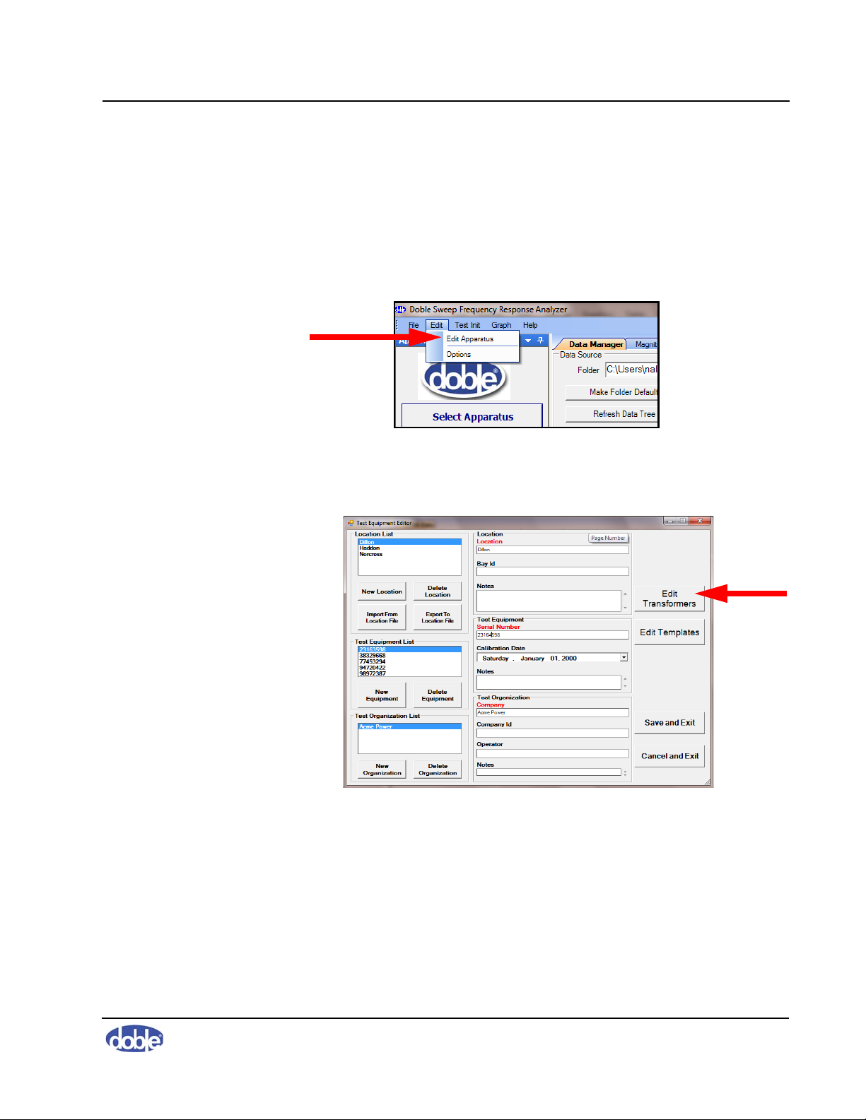
Edit Apparatus (Figure 3.5).
Figure 3.5 Edit Apparatus Option on Edit Menu
The Test Equipment Editor window opens (Figure 3.6).
Edit menu and select
Figure 3.6 Test Equipment Editor
2. Click the
Edit Transformers button on the right.
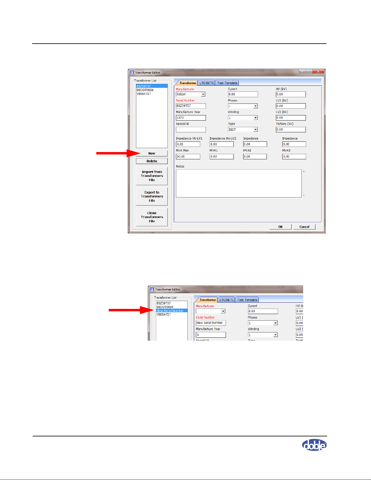
The Transformer Editor window opens, displaying the Transformer tab
(Figure 3.7 on page 3-6).
72A-2570-01 Rev. K 07/2011 3-5
Sweep Frequency Response Analyzer (SFRA) User Guide
Figure 3.7 Transformer Tab of Transformer Editor Window
3. Click
New (Figure 3.7).
The New Serial Number listing is highlighted (Figure 3.8).
Figure 3.8 New Serial Number Listing
4. Enter
5. Enter
6. Click the
Leads in the Manufacturer field.
0 in the Serial Number field.
Test Templates tab.
Note that the new serial number, 0, appears in the Transformer list
(item #1 Figure 3.9 on page 3-7).
3-6 72A-2570-01 Rev. K 07/2011
Loading...