

Page 1

M4000 Insulation Analyzer
User Guide
July 22, 2005
Doble Engineering Company
85 Walnut Street
Watertown, Massachusetts 02472-4037
(USA)
PN 500-0110 72A-1230 Rev. F
Page 2

Copyright © 2000
By Doble Engineering Company
All Rights Reserved.
This Manual is the sole property of the Doble Engineering Company (Doble)
and is provided for the exclusive use of Doble Clients under contractual
agreement for Doble Test Equipment and Services.
In no event does the Doble Engineering Company assume the liability for any
technical or editorial errors of commission, or omission; nor is Doble liable for
direct, indirect, incidental, or consequential damages arising out of the use or
inability to use this Manual.
Government Restricted Rights Legend: Use, duplication, or disclosure by the
U.S. Government is subject to restrictions as set forth in subparagraphs (c)(1)
and (c)(2) of the Commercial Computer Software - Restricted Rights Clause at
FAR 52.227-19.
This manual is protected by copyright, all rights reserved, and no part hereof
may be photocopied or reproduced in any form without prior written consent
of the Doble Engineering Company.
Copyright
By Doble Engineering Company
All Rights Reserved.
©
2000
Page 3

Preface
Structure of this Manual
This manual consists of 4 chapters and 4 appendices.
Chapter 1 “Introduction” introduces the functions and
Chapter 2 “M4000 Software” provides an overview of M4000
Chapter 3 “Running M4000 Tests” describes procedures for
Chapter 4 “M4100 Instrument Troubleshooting” provides initial
Appendix A “M4000 Components Lists” describes accessories
architecture of the M4000 Insulation Analyzer, as well
as important safety considerations for its use.
software and its installation.
executing specimen tests.
steps in troubleshooting problems and isolating a
problem to either the M4100 or M4200c.
included with the M4000 Insulation Analyzer.
Appendix B “Warranty” provides Doble warranty provisions
applicable to the M4000.
Appendix C “Error Messages” lists error message numbers and
descriptions.
Appendix D “Part Numbers” lists the M4000 Insulation Analyzer
part numbers.
July 22, 2005
72A-1230 Rev. F i
Page 4

Conventions Used in this Manual
The following terms and typographical conventions are used in the manual:
Convention Description
Windows Refers to the Microsoft Windows operating system,
Click Quickly press and release the left mouse button.
Double-click Quickly press and release the left mouse button twice
Select Position the cursor on the desired option and click the
Version 98 or later.
without moving the mouse.
left mouse button once. Or, highlight the desired
option using the arrow keys and press
ENTER. Or, press
ALT and the underlined letter.
July 22, 2005
Press Type a single keyboard key. For example, press
ENTER.
FN+(appropriate key) Press and hold the FN key, and press (appropriate
key).
Bold Courier Text Indicates characters to be typed.
ii 72A-1230 Rev. F
Page 5

M4000 Insulation Analyzer User Guide
1. Introduction
Measurement Principles ..................................................................................................................... 1-1
Safety .................................................................................................................................................. 1-1
M4000 Components ........................................................................................................................... 1-2
M4100 Instrument ........................................................................................................................ 1-2
M4200c Controller ....................................................................................................................... 1-5
Third-Party Controller.................................................................................................................. 1-7
M4000 Software........................................................................................................................... 1-7
Optional M4150 And M4151 Field Calibration References........................................................ 1-7
Doble Standard Turns Ratio Capacitor ........................................................................................ 1-8
External Reference ....................................................................................................................... 1-8
M4300 Transport.......................................................................................................................... 1-8
Doble Test Assistant (DTA) Software ......................................................................................... 1-9
M4110 Leakage Reactance Interface ........................................................................................... 1-9
Operating with the M4300 Transport ............................................................................................... 1-10
Storage and Moving Mode.........................................................................................................1-10
Testing Mode.............................................................................................................................. 1-13
When Finished Testing............................................................................................................... 1-15
M4000 PC Cable ........................................................................................................................ 1-16
Transport, Storage and Shipping ...................................................................................................... 1-17
Transporting and Storing the M4000 ......................................................................................... 1-17
Shipping Instructions.................................................................................................................. 1-18
Safety Considerations....................................................................................................................... 1-19
Definitions.................................................................................................................................. 1-19
Safety Practices – General Rules ............................................................................................... 1-20
Clearances .................................................................................................................................. 1-20
Grounding................................................................................................................................... 1-21
Personnel Safety......................................................................................................................... 1-21
M4000 Connections ................................................................................................................... 1-22
M4000 Operation ....................................................................................................................... 1-23
M4000 Safety Features............................................................................................................... 1-23
Safety Precautions ...................................................................................................................... 1-25
Safety Precautions for Various Types of Apparatus .................................................................. 1-26
Safety Summary ......................................................................................................................... 1-28
July 22, 2005
72A-1230 Rev. F 1
Page 6

2. M4000 Software
Upgrading or Installing M4000 Software........................................................................................... 2-1
Software Installation ........................................................................................................................... 2-1
M4000 Software ........................................................................................................................... 2-1
Doble Test Assistant (DTA) Software (Optional)........................................................................ 2-5
Optimization ....................................................................................................................................... 2-5
COM port Setting ......................................................................................................................... 2-5
Mouse Settings ............................................................................................................................. 2-5
Time/Date Format......................................................................................................................... 2-6
Introduction to M4000 Software......................................................................................................... 2-6
What’s New .................................................................................................................................. 2-6
The M4000 Program..................................................................................................................... 2-7
Icons.............................................................................................................................................. 2-7
Menu Bar ......................................................................................................................................2-8
Clipboard Test Mode .......................................................................................................................... 2-9
Menu Items ....................................................................................................................................... 2-11
Mode Menu................................................................................................................................. 2-11
Test Menu ................................................................................................................................... 2-11
Diagnostics ................................................................................................................................. 2-12
July 22, 2005
View Menu ................................................................................................................................. 2-12
Tools Menu................................................................................................................................. 2-12
Temperature Correction.................................................................................................................... 2-12
Configuration .................................................................................................................................... 2-13
System Configuration ................................................................................................................. 2-13
Clipboard Configuration.............................................................................................................2-14
DTA Field Configuration ........................................................................................................... 2-16
Instrument Configuration ........................................................................................................... 2-18
Advanced Configuration............................................................................................................. 2-19
Using Help ........................................................................................................................................2-21
Contents...................................................................................................................................... 2-21
About M4000 For Windows....................................................................................................... 2-22
Printer Setup ..................................................................................................................................... 2-22
Printing.............................................................................................................................................. 2-22
3. Running M4000 Tests
2 72A-1230 Rev. F
Page 7

M4000 Insulation Analyzer User Guide
Entering Clipboard Information ......................................................................................................... 3-1
Nameplate Information ................................................................................................................ 3-1
Administrative Information.......................................................................................................... 3-2
Test Conditions ............................................................................................................................ 3-3
Test Results Information .................................................................................................................... 3-4
Running Single and Multiple Clipboard Tests ................................................................................... 3-6
Raising Test Voltage .................................................................................................................... 3-7
Test Results .................................................................................................................................. 3-8
Clearing Test Results ................................................................................................................. 3-10
Saving Test Results .................................................................................................................... 3-11
Graphing Test Results ................................................................................................................ 3-11
External Reference/Source Test (Optional Software) ...................................................................... 3-12
Running A UST Test.................................................................................................................. 3-12
Running a GST-Guard Test........................................................................................................3-14
Leakage Reactance Test (Optional Software) .................................................................................. 3-16
DTA Mode........................................................................................................................................ 3-17
DTA Tests......................................................................................................................................... 3-17
DTA Data Manager .......................................................................................................................... 3-18
Preparing for a DTA Test ................................................................................................................. 3-19
Starting a DTA Test.......................................................................................................................... 3-19
DTA Icons and Function Keys ......................................................................................................... 3-24
Using A Resonator............................................................................................................................ 3-25
Operating Procedure of Type C Resonating Inductor................................................................ 3-26
General Description of Type C-1 Coupler - RIV Test Procedure .................................................... 3-28
July 22, 2005
4. M4100 Instrument Troubleshooting
Assigning A Trouble To The M4100 Instrument (Or The M4200c Controller)................................ 4-1
Quick Checks ............................................................................................................................... 4-1
Troubleshooting Resources .......................................................................................................... 4-2
Isolating Trouble .......................................................................................................................... 4-3
Avoiding Problems....................................................................................................................... 4-4
Detailed Troubleshooting Of The M4100 Instrument........................................................................ 4-5
Overview of M4100............................................................................................................................ 4-7
Overview of Individual Replaceable Components............................................................................. 4-9
Troubleshooting from Symptoms..................................................................................................... 4-12
Troubleshooting from Error Messages.............................................................................................4-16
72A-1230 Rev. F 3
Page 8

Troubleshooting from Diagnostics ................................................................................................... 4-21
Running Diagnostics................................................................................................................... 4-21
System Status.............................................................................................................................. 4-23
Calibration Verification.............................................................................................................. 4-26
Field Recalibration ..................................................................................................................... 4-31
Subsystem Diagnostics............................................................................................................... 4-34
M4100 Component List.............................................................................................................. 4-38
Thermal Profile........................................................................................................................... 4-39
Communications Loopback Test................................................................................................ 4-40
Running Other Tests ......................................................................................................................... 4-42
Checking the High Voltage Test Cable ...................................................................................... 4-42
Checking the Low Voltage Test Leads.......................................................................................4-42
Checking M4100 Guard-to-Ground Insulation .......................................................................... 4-43
Checking Instrument Accuracy in the Field............................................................................... 4-43
Voltage Verification ................................................................................................................... 4-44
Accessing M4100 Components ........................................................................................................ 4-46
Removing the Front and Top Covers ......................................................................................... 4-46
Removing the Card Cage Cover................................................................................................. 4-48
M4100 Internal Checks..................................................................................................................... 4-50
July 22, 2005
Fan Operation ............................................................................................................................. 4-50
Low-Voltage Power Checkout ................................................................................................... 4-51
Guard-to-Ground Shorting Problems ......................................................................................... 4-51
LVPS Fuses ................................................................................................................................ 4-52
W8/W9/W11 Cable Checkout.................................................................................................... 4-53
Orange Cable Checkout.............................................................................................................. 4-54
Transformer Checks ................................................................................................................... 4-54
W46 Cable Checkout..................................................................................................................4-55
4 72A-1230 Rev. F
Page 9

M4000 Insulation Analyzer User Guide
Replacing M4100 Components ....................................................................................................... 4-56
Returning Replaced Components............................................................................................... 4-57
Removing and Replacing the Front Panel Assembly................................................................. 4-58
Replacing the Guard Front Panel Board .................................................................................... 4-61
Replacing the Amplifier Assembly ............................................................................................ 4-63
Replacing the Guard Mode Switch Board.................................................................................. 4-66
Replacing the Timing Board ......................................................................................................4-68
Replacing the DSP/CPU Board.................................................................................................. 4-70
Replacing the Safety Board........................................................................................................ 4-72
Replacing the Main Reference Assembly .................................................................................. 4-74
Replacing the Guard Board ........................................................................................................ 4-76
Replacing the Low Voltage Power Supply Board ..................................................................... 4-78
Replacing the Heater/Temperature Controller Board ................................................................ 4-80
Replacing the Optional Field Calibration Reference ................................................................. 4-82
Replacing the I/O Protection Board ........................................................................................... 4-83
Replacing the Transformer......................................................................................................... 4-85
Replacing the HV Pothead ......................................................................................................... 4-91
Replacing the Fan Filter ............................................................................................................. 4-93
Replacing the Fan....................................................................................................................... 4-94
Appendix A. M4000 Components Lists
M4000 Insulation Analyzer................................................................................................................A-1
Accessory Bag ....................................................................................................................................A-2
Documentation Bag ............................................................................................................................A-4
Appendix B. Warranty
RENTAL EQUIPMENT ....................................................................................................................B-1
PURCHASED EQUIPMENT ............................................................................................................B-1
Limited Warranty .........................................................................................................................B-1
Software Limited Warranty..........................................................................................................B-2
Limitations of Remedies ..............................................................................................................B-2
For Equipment Maintenance, Contact:.........................................................................................B-3
Appendix C. Error Messages
M4100 Instrument Run Time Error Messages ...................................................................................C-1
July 22, 2005
72A-1230 Rev. F 5
Page 10

M4000 Firmware/Application Errors ................................................................................................ C-2
M4000 Communications Errors......................................................................................................... C-3
Appendix D. Part Numbers
July 22, 2005
6 72A-1230 Rev. F
Page 11

1. Introduction
The M4000 Insulation Analyzer is used to determine the insulation quality of
high-voltage power apparatus in the field. This portable test set incorporates
automated Doble Testing with high accuracy and sensitivity, over a wide range
of values, and with minimal susceptibility to electrostatic interference and
noise.
Measurement Principles
The M4000 generates a 0-12 kV test signal with an internal sine wave
generator, a 3 kVA power amplifier and a step-up isolation transformer. The
M4000 then measures the voltage and current of the specimen and a reference
impedance by periodically sampling instantaneous values with an A/D
converter. The M4000 then calculates and reports test results by converting the
sampled data into vector (magnitude and phase) quantities and applying
conventional ac circuit theory. All reported results – including power loss,
power factor and capacitance – are derived from the vector voltage and
current.
Safety
The M4000 rejects interference through the judicious application of shielding,
line-synchronized reversal, and line frequency modulation (FM). The first two
techniques are similar to those employed in the earlier Doble M2H product
line. The FM technique involves running tests at sinusoidal frequencies 5% (or
even 10%, if necessary) above and below the line frequency and averaging the
results. The choice is user configurable.
The inevitable interference current component is removed from the sampled
data set before test results are calculated using synchronous detection. This is
a mathematical process that separates out a single frequency component in a
given signal. It is analogous to a bandpass filter centered at the test frequency.
Synchronous detection is also useful for removing harmonic distortion and
random noise in the test signal itself.
The M4000 is designed to drive grounded and ungrounded specimens at lethal
voltages and high power levels. Conventional ground-fault and currentlimiting schemes cannot be used to protect the operator under these test
conditions. Therefore, the M4000 implements special safety techniques to
minimize risk to the equipment operator.
July 22, 2005
72A-1230 Rev. F 1-1
Page 12

M4100 Instrument
Both an operator and safety supervisor must be present when specimens are
tested. Each person holds a safety switch that directly controls the output of
the power amplifier through redundant electromechanical relays. In addition,
the control processor can vote to disable the dc supply to the safety relay coils,
thereby disabling the amplifier output if certain conditions are not met.
NOTE For greater safety details, see ”Safety Practices – General Rules”
on page 1-20.
M4000 Components
The M4000 Insulation Analyzer consists of the following components:
• M4100 Instrument
• M4200c Controller or Third-Party Controller
• M4000 Software
July 22, 2005
M4100 Instrument
The following auxiliary components are optional:
• M4150 or M4151 Field Calibration Reference
• M4300 Transport
• Leakage Reactance Test Software
• External Reference Test Software
•DTA Software
• M4110 Leakage Reactance Interface
• M4120 External Reference Module
• Doble Standard Turns Ratio Capacitor
• Safety Strobe
• Temperature and Humidity Probe
The M4100 instrument supplies test voltage and test current to insulation
specimens. The M4100 instrument also contains measuring circuits to
determine the condition of the insulation under test, as well as direct control
safety circuits to ensure electrical safety of personnel and test apparatus.
The M4100 instrument has a time base generator that may be synchronized
either with the power system supplying power to the test instrument, or with
an internal crystal oscillator. This choice allows the test operator to select one
of two modes of test operation, Line Sync Reversal or Line Frequency
Modulation. When Line Sync Reversal Mode is selected, the time base is
synchronized to the power source and the test will use the standard Doble
1-2 72A-1230 Rev. F
Page 13

M4000 Insulation Analyzer User Guide
polarity reversal technique to reverse the effects of electrostatic interference.
Selecting the Line Frequency Modulation Mode of operation will synchronize
the time base generator to the crystal oscillator. Two tests will be run for each
programmed test sequence. The first test is run at a frequency of 57 Hz and the
second test is run at 63 Hz. The measured test results of each test are combined
and averaged to give a 60 Hz equivalent test result. When operating in the 50
Hz frequency, the same technique will apply. The first test will run at 47 Hz,
and the second test will run at 53 Hz. This mode of test eliminates electrostatic
interference from measurement, by avoiding measurement at power line
frequency. It is also possible to select ± 10% of power line frequency as well.
Safety circuits have been designed into the M4100 instrument to ensure safety
of personnel. High voltage will not be supplied by the instrument if either of
the following circuits and conditions are not satisfied:
• The ground safety circuit verifies that the #6 bare copper safety
ground, which is attached from the instrument to the apparatus earth
ground, is at the same potential as the power supply ground.
• Two safety switches must be attached to the M4100 instrument front
panel and in the closed or depressed position prior to testing. One
switch is held by the M4000 Insulation Analyzer operator and the
second switch is held by a safety supervisor. The M4100 can be
configured to require both switches to be opened between test
sequences for the M4000 Insulation Analyzer to operate. Release of
one or both switches will terminate the test sequence and high voltage
potential.
July 22, 2005
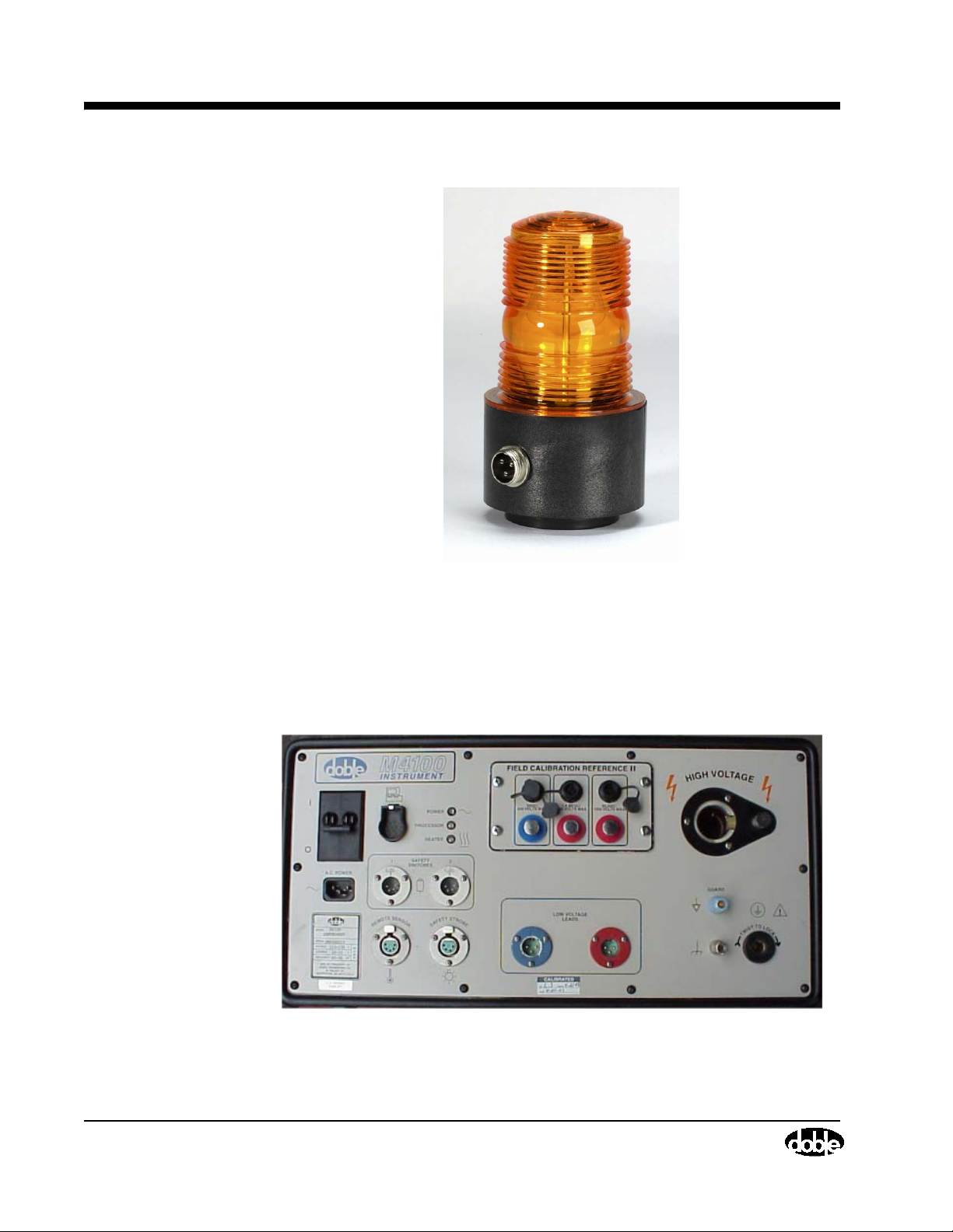
A safety strobe light can be used in conjunction with the instrument and is
plugged into the front panel of the M4100. Whenever high voltage potential is
applied from the M4100, the safety strobe light will be energized and flashing.
Safety strobe connection will be required in order to operate the M4000
Insulation Analyzer, unless the default system configuration has been
modified to allow for the absence of a safety strobe. In this case, the strobe
connector can be removed from the M4100 front panel.
72A-1230 Rev. F 1-3
Page 14
M4100 Instrument
July 22, 2005
Figure 1.1 Safety Strobe
Two optional items found on the M4100 front panel are the M4151 Field
Calibration Reference, which will be discussed below, and a Temperature and
Relative Humidity sensor. The Temperature and Relative Humidity Sensor
will process temperature and humidity readings at the time of test.
Front Panel
Figure 1.2 M4100 Instrument
1-4 72A-1230 Rev. F
Page 15
M4200c Controller
M4000 Insulation Analyzer User Guide
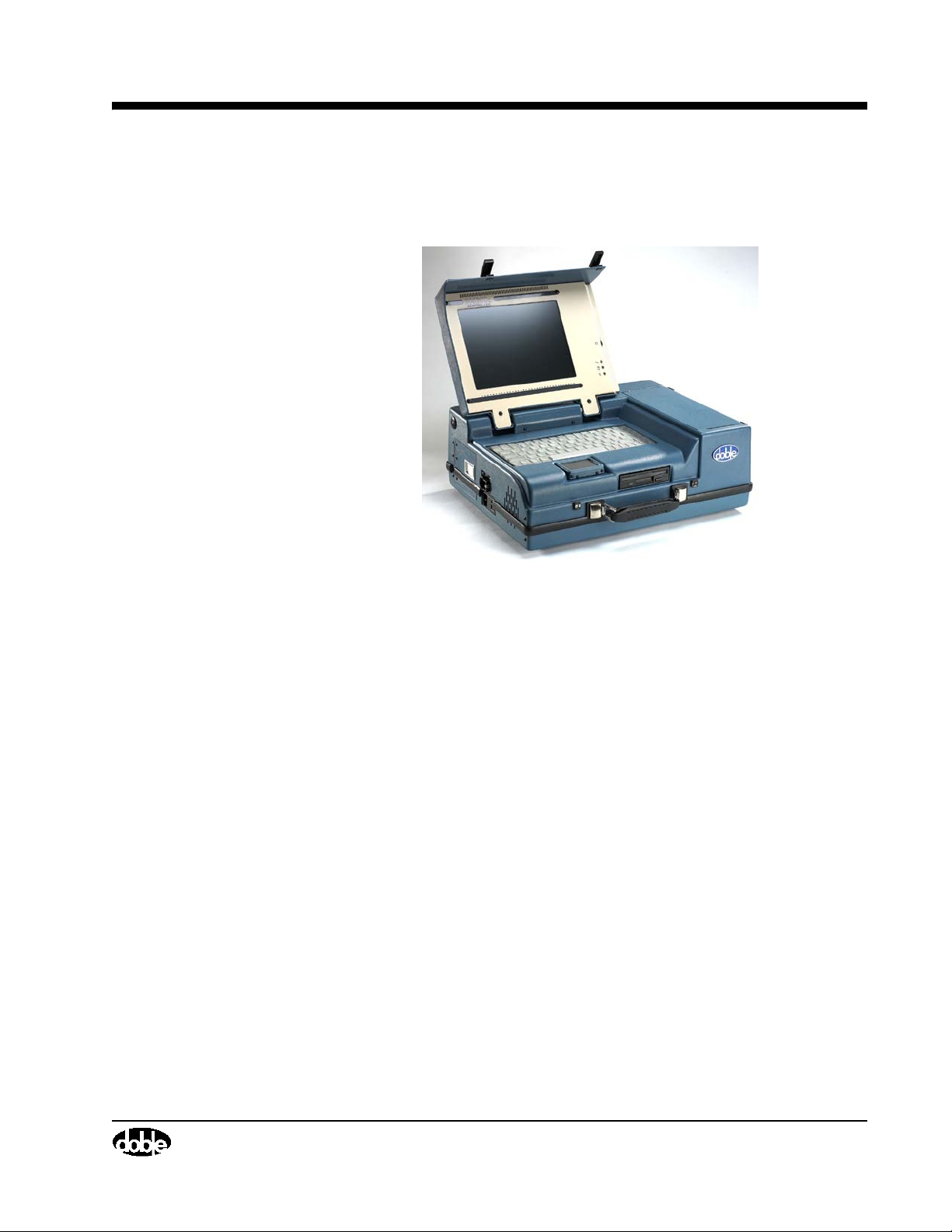
Figure 1.3 M4200c Controller
• The M4200c Controller is the interface between the operator and the
M4000 Insulation Analyzer. The color display, control, data storage,
printing and communication functions are all provided by the M4200c
Controller. This component is covered in detail in a separate manual.
• The M4200c has been specifically designed and built to operate in
outdoor substations and other environments hostile to electronic test
equipment. The unit has been hardened to electrostatic discharge
(ESD) and radio frequency interference (RFI) to reduce or eliminate
their effects on internal electronic circuits.
• The outer case of the M4200c is made of ABS plastic over an
aluminum chassis that makes it rugged and suitable for transporting to
remote sites.
• The display is a six-inch by eight-inch color transflective liquid crystal
display (LCD) that runs in the VGA mode. The display has high
contrast in bright sunlight, and has backlight control for low ambient
light conditions. An LCD heater is installed to allow for use in cold
weather. An external monitor may be used in place of the LCD screen.
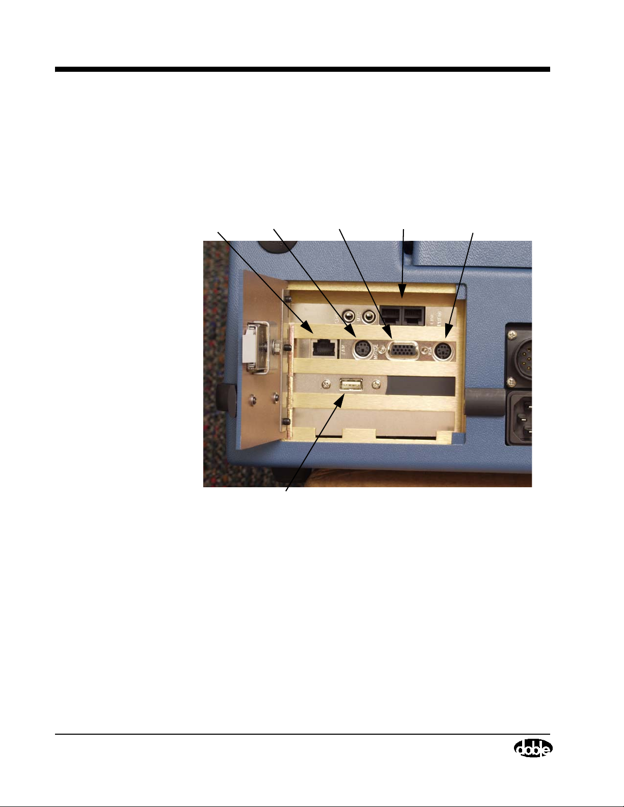
Access to the external display connector is found behind the access
door on the left side of the M4200c Controller.
July 22, 2005
72A-1230 Rev. F 1-5
Page 16
M4200c Controller
• The keyboard is a standard notebook-type keyboard with a flexible
skin around the keys to prevent dirt and moisture from contaminating
the internal electronics and causing failure of the keyboard. An
external keyboard may be used in place of this keyboard. Access to the
external keyboard connector is to the right of the video connector
behind the access door on the left hand side of the M4200c Controller.
LAN Ext. Mouse Ext. Monitor Modem Ext. Keyboard
July 22, 2005
USB
Figure 1.4 M4200c Controller External Connections
• The M4200c has a pointer device installed below the keyboard on the
front panel to allow for the use of mouse control of the display cursor.
A port on the left-hand side of the M4200c allows for the use of an
external, serial mouse.
• The M4200c has a built-in 200 dot per inch (dpi) graphic printer/
plotter. Paper for the printer/plotter is an uncoated thermal FAX paper
provided by Doble.
• The M4200c is equipped with an internal FAX/Modem board that may
be used to transfer data when used with the optional Doble Test
Assistant (DTA) program.
• The M4200c has a built in ethernet connection.
1-6 72A-1230 Rev. F
Page 17
Third-Party Controller
Certain PC’s using a Windows-based operating system available from other
suppliers can be used as a system controller in lieu of the M4200c controller.
These alternative machines can be used to control M4000 operations.
M4000 Software
Software provided with the M4200c or available to be loaded onto a ThirdParty Controller includes a program to run the M4000 Insulation Analyzer,
and if desired, the optional Leakage Reactance Test, External Reference Test,
and Doble Test Assistant (DTA) programs. For more information, refer to
Chapter 2.
M4000 Insulation Analyzer User Guide
• The M4200c has a built in USB port.
• Data may be stored on an internal hard drive or on a 3 1/2 - inch floppy
disk via the floppy disk drive located in the front of the controller.
Optional M4150 And M4151 Field Calibration References
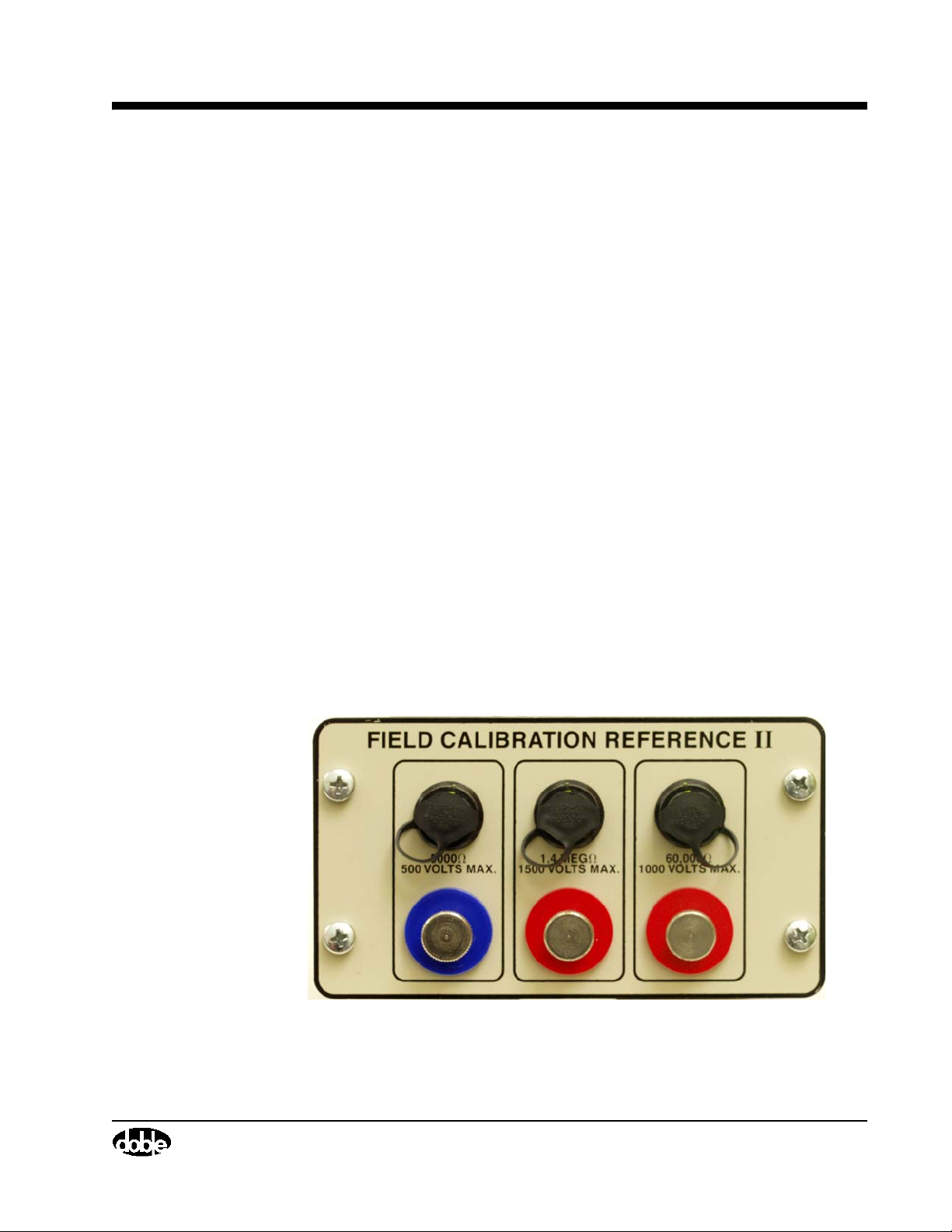
The purpose of the M4150 and M4151 Field Calibration References are to
provide a means of obtaining System Status, Calibration Verification, and
Field Recalibration Tests of the M4100 instrument in the field. (For an
explanation of these tests, refer to ”Running Diagnostics” on page 4-21). The
Field Calibration Reference is mounted in the front panel of the M4100
instrument.
July 22, 2005
Figure 1.5 M4151 Field Calibration Reference
72A-1230 Rev. F 1-7
Page 18
Doble Standard Turns Ratio Capacitor
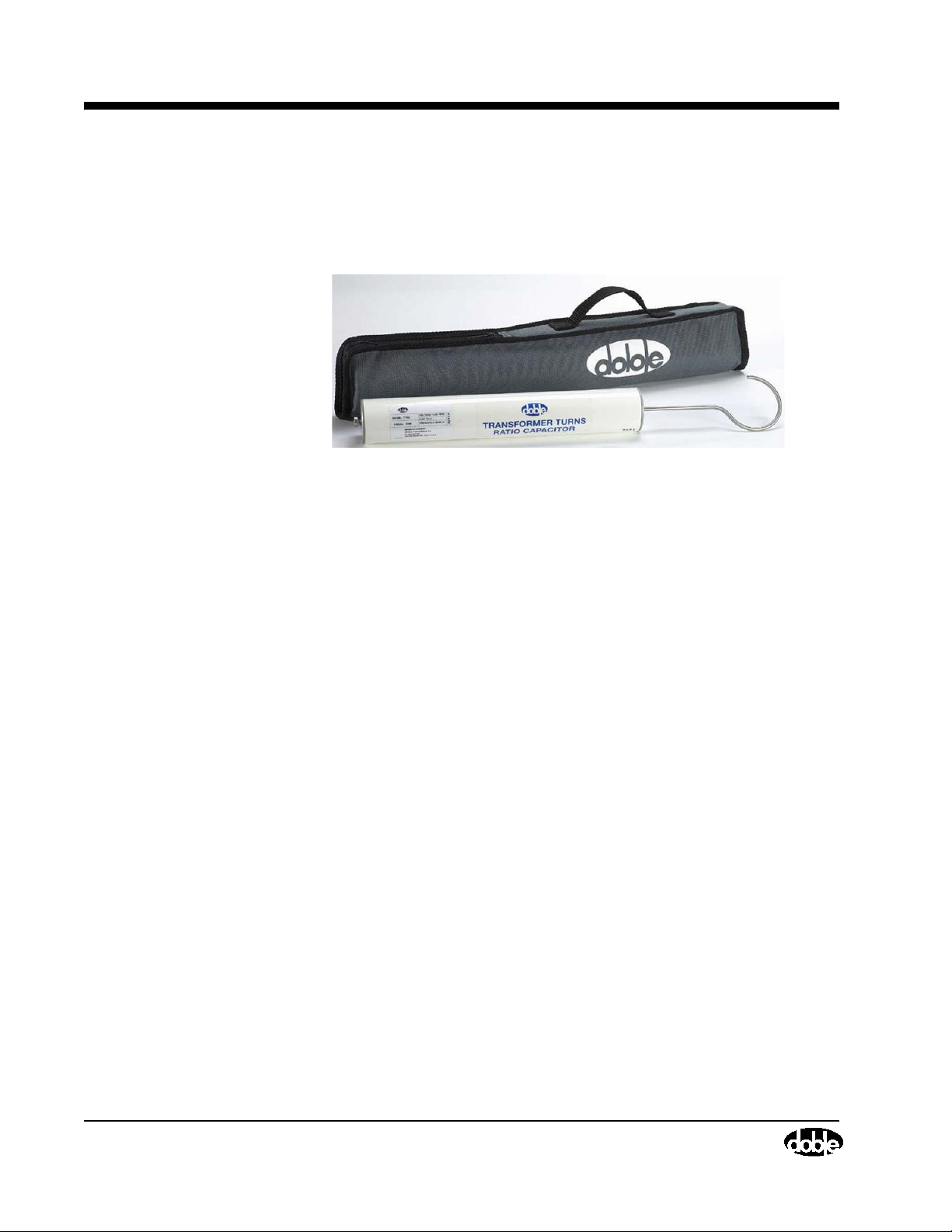
Doble Standard Turns Ratio Capacitor
This is an optional small portable capacitor that can be energized at 10 kV for
performing turns ratio tests at high voltages with the M4000.
Figure 1.6 Doble Turns Ratio Capacitor
External Reference
M4300 Transport
July 22, 2005
This is an optional feature allowing the tester to test apparatus at their full
operating voltage using the M4000, providing a suitable external power source
and reference are provided by the user.
The M4300 Transport is an option for the M4000 Insulation Analyzer that
provides a means to move and store the M4000 system. It is also a platform for
the field, from which the M4000 can be easily used and operated. Refer to
”Storage and Moving Mode” on page 1-10 and ”Testing Mode” on page 1-13.
If a PC is to be substituted for the Controller, a support panel to be mounted on
the Controller support frame can be supplied.
1-8 72A-1230 Rev. F
Page 19

M4000 Insulation Analyzer User Guide
Doble Test Assistant (DTA) Software
Optional Doble Test Assistant® (DTA) software provides standardized
apparatus test procedures and templates, data management, and optional
expert system software for insulation condition assessment. See Chapters 2
and 3 for further details.
M4110 Leakage Reactance Interface
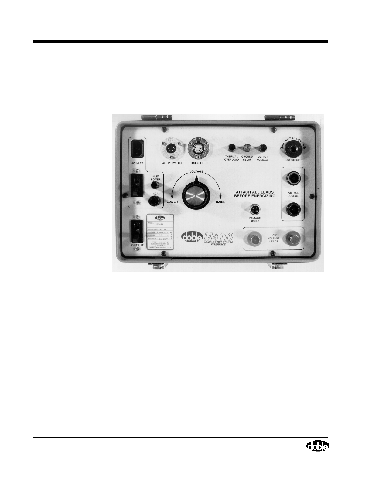
This optional interface contains the circuitry necessary to convert the voltage
and current, measured during a Leakage Reactance test on a transformer, into
a form that can be measured by the M4100 Instrument. It also contains a
variac so that the proper test voltage can be obtained. The Leakage Reactance
test cannot be made without either this Interface or the M4130 Leakage
Reactance Module, and the accompanying software.
July 22, 2005
Figure 1.7 M4300 Transport
72A-1230 Rev. F 1-9
Page 20
Storage and Moving Mode
When using this interface, the standard M4000 safety switch and safety strobe
are used. The necessary current and voltage cables are provided for connection
to the transformer, along with the necessary software, so that this becomes a
self-contained kit for this test. The user is only limited by the size of the variac
provided.
July 22, 2005
Figure 1.8 M4110 Leakage Reactance Interface
Operating with the M4300 Transport
The M4000 Insulation Analyzer is designed to be assembled on the M4300
Transport for storage, moving, and testing. When the M4000 is used with the
M4300 Transport, it can be set up in the following modes:
• Storage and Moving Mode
• Testing Mode
Storage and Moving Mode
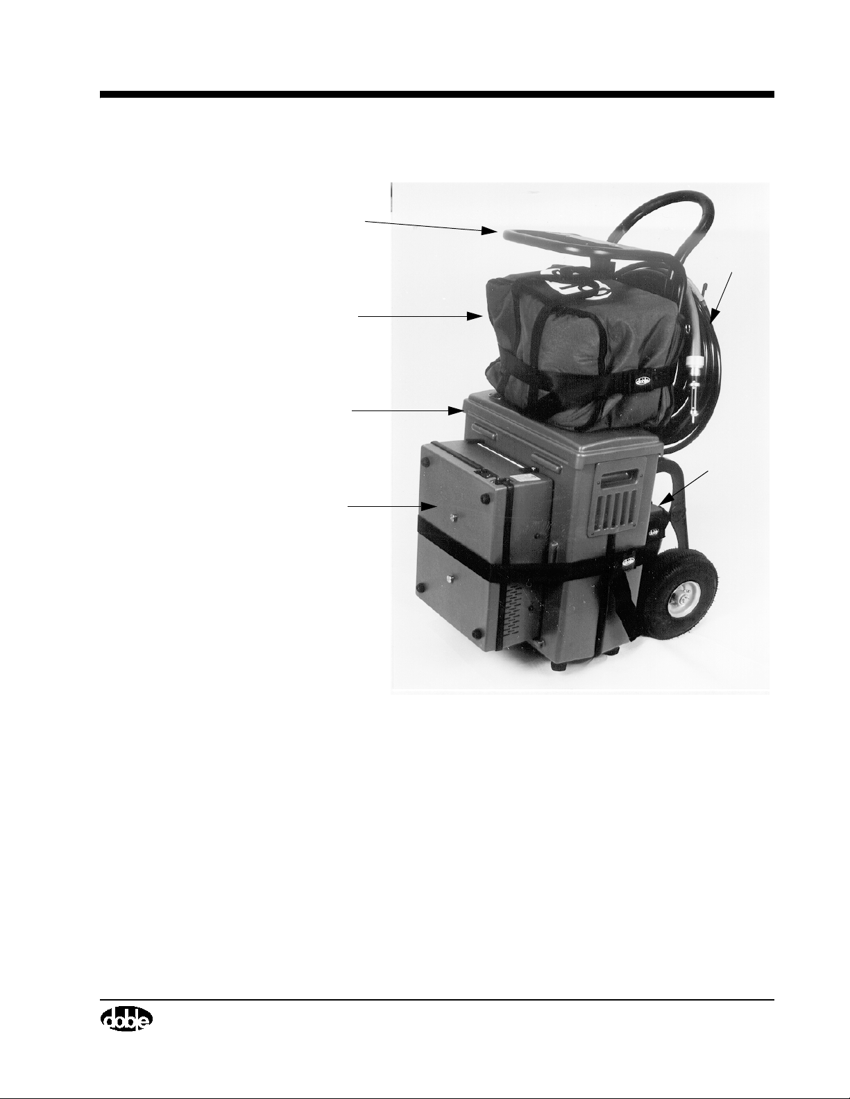
The storage and moving mode will allow the user to transport and store the
M4000
components of the M4000 fit in a single, packaged unit (Figure 1.9).
Insulation Analyzer. The M4300 Transport is designed so that all the
1-10 72A-1230 Rev. F
Page 21
Controller
Support Frame
Cable Carry
Bag
M4100
Instrument
M4200c
Controller
M4000 Insulation Analyzer User Guide
High
Voltage
Cable
Oil Test
Cell
Figure 1.9 M4000 Insulation Analyzer in Storage Mode
The recommended assembly steps for the Storage and Moving Mode is as
follows:
1. Remove the M4200c Controller Support frame from the M4300 Transport.
Lay the M4300 Transport down on its back, on a level surface so that the
wheels and handle touch the surface.
2. Verify that the cover is installed on the M4100 Instrument front panel.
Position the M4100 Instrument on the M4300 Transport as shown in the
above picture.
July 22, 2005
72A-1230 Rev. F 1-11
Page 22

Storage and Moving Mode
NOTE The M4200c Controller Support frame should not be used for lifting the
3. Position the closed M4200c Controller upside down into the area with the
projections of the top cover of the M4100 Instrument. Buckle and tighten
the strap snugly around both the M4100 Instrument and the M4200c
Controller.
4. Lift the M4300 Transport into the upright position.
5. Place the Documentation Bag and Cable Carry Bag on top of the M4100
Instrument top cover. Buckle and tighten the strap to secure.
6. Place the Oil Test Cell on the brackets provided between the wheels on the
rear of the M4300 Transport, and secure it with the strap provided.
7. Place the High Voltage Cable into the brackets provided on the top, rear
part of the M4300 Transport and secure it with the strap provided.
8. Place the M4200c Controller Support frame into the tubes provided so that
the end faces forward.
M4300 Transport.
July 22, 2005
The M4000 Insulation Analyzer is now in Storage and Moving Mode.
1-12 72A-1230 Rev. F
Page 23
Testing Mode
M4000 Insulation Analyzer User Guide
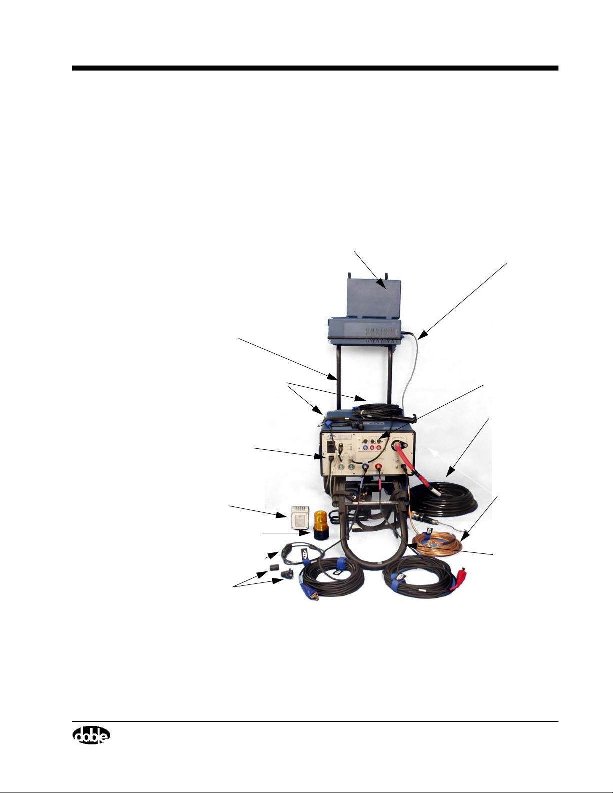
When assembled in the Testing Mode, the M4300 Transport serves as the field
desk for the M4000 Insulation Analyzer. The Testing Mode (Figure 1.10) was
designed to take advantage of the M4100 instrument's concentrated cluster of
connections, providing the user with a comprehensible testing setup and a
user-friendly environment while testing.
Intercase
M4200c Controller
Controller Support
Frame
Communication
Cable
Safety Switch 1&2
120/240 V
Power Cable
Remote Temperature
Humidity Sensor
Safety Strobe
Diagnostic Test
Adapter Cable
Loopback Test
Connectors
Blue Low
Voltage Cable
Red Low
Voltage Cable
M4151 Calibration
Reference
High
Vo lt ag e
Cable
Safety
Ground
Transporter
July 22, 2005
Figure 1.10 M4000 in Testing Mode
72A-1230 Rev. F 1-13
Page 24
Testing Mode
The following instructions describe how to assemble the components of the
M4000 Insulation Analyzer into the Testing Mode, from the Storage and
Moving Mode:
WARNING When preparing for a test, do not attach any test leads to the apparatus to
be tested without first attaching them to the M4100 test set!
1. With the M4300 Transport in the upright position, remove the M4200c
Controller Support frame, the Cable Carry bag, the Documentation bag,
the High Voltage Cable, and the Oil Test Cell from the rear of the
Transport.
2. Carefully lay the M4300 Transport down on its back on a level surface.
The handle should face the specimen to be tested.
3. Place the M4200c Controller Support frame into the tubes provided on the
M4300 Transport bottom plate, near the M4100 Instrument rubber feet.
The top of the frame must extend away or opposite to the handle.
4. Remove the M4200c Controller from the top surface of the M4100
Instrument. Place the M4200c Controller on the Support frame and lock it
in place.
July 22, 2005
5. Remove the top cover from the M4100 Instrument top panel. The M4100
Instrument is ready for connecting the cables.
6. The M4100 Instrument top panel receptacles are designed to only accept
the functionally correct cables. Place each cable into the respective
receptacle. The only interchangeable cables are the Safety Switches.
NOTE Inspect all cables for cracks or other damage before using.
7. Connect the Safety Ground cable to the M4100 Instrument, and to the
ground of the specimen to be tested. The Safety Ground Cable should be
the first connection to be made and the last one disconnected from the
M4100 Instrument.
8. Connect the M4100 Instrument and the M4200c Controller to the Power
Receptacle Box located at the bottom of the handle of the M4300
Transport. A separate receptacle box is also provided for cases where the
M4000 Insulation Analyzer is used away from the M4300 Transport. As
shipped from Doble, the 120 VAC receptacle in the M4200c Controller is
located under a yellow tag which states, “NOTICE: READ ENCLOSED
MICROSOFT SOFTWARE LICENSE BEFORE USING”. The license
agreement and documentation are in the Documentation bag. Please
comply with the notice and remove the tag to plug in the cable.
9. Interconnect the M4100 Instrument and the M4200c Controller using the
gray snap-in cable provided.
1-14 72A-1230 Rev. F
Page 25
M4000 Insulation Analyzer User Guide
10. Connect the two safety switches to the two receptacles labeled “Safety
Switches” on the front panel of the M4100 Instrument.
11. Connect, as necessary, the red and blue Low-Voltage leads to the
corresponding color coded receptacles labeled “LOW VOLTAGE
LEADS”, on the front panel of the M4100 Instrument. To avoid
unintended measurements, connect only the low voltage lead(s) to be used
for the next text.
12. Connect the Safety Strobe to the receptacle labeled “SAFETY STROBE”
on the front panel of the M4100 Instrument. The strobe has a magnetic
base that can be placed on a grounded steel structure, where it is visible to
all personnel around the testing area.
13. Connect the Temperature and Relative Humidity Sensor to the receptacle
labeled “REMOTE SENSOR” on the front panel of the M4100
Instrument. This sensor will automatically record the ambient temperature
and humidity. The sensor has a magnetic base and should be placed on a
grounded structure, in the shade, to record the most accurate temperature
and humidity. The M4100 Instrument will operate without this option.
14. Connect the High-Voltage Cable to the receptacle labeled “HIGH
VOLTAGE” on the front panel of the M4100 Instrument. Ensure that the
High Voltage Cable is fully inserted and latched into the receptacle.
15. Connect the M4000 Power Receptacle box to a 120 or 240 VAC source.
This should be the last connection to be made.
16. The M4000 Insulation Analyzer is ready to be connected to the specimen
to be tested. Connections to the specimen are described in the Doble Test
Procedures manual.
NOTE When the M4000 Insulation Analyzer is assembled in the Test Mode it should
not be moved. However if minor repositioning is necessary it should be done
by lifting the M4300 handle a few inched off the surface.
When Finished Testing
When tests are finished, and before starting the Storage and Moving Mode
assembly procedure, make sure that all the data have been saved and that the
application programs that were used have been closed before shutting power
off to the M4200c Controller.
WARNING When finished testing, do not remove any of the test leads from the test set
before first removing them from the apparatus just tested!
July 22, 2005
72A-1230 Rev. F 1-15
Page 26

M4000 PC Cable
NOTE Data will be lost if all software application programs are not closed before
M4000 PC Cable
the M4200c is powered down.
To set the M4000 to the Storage and Moving Mode, reverse the previous setup
procedure (”Testing Mode” on page 1-13), keeping in mind that the Safety
Ground cable is the last cable to be disconnected from the M4100 instrument.
Refer also to ”Storage and Moving Mode” on page 1-10.
There is a cable with connectors designed to attach your M4100 to a thirdparty controller of your choice. This cable is supplied as a way to offer users
an even higher level of product reliability. With the M4000 PC Cable, the user
can continue to test even if the M4200c Controller suffers a serious failure, by
using the cable to connect the M4100 Instrument directly to the user’s own
PC.
To be prepared to use this cable, you must have the DTA and M4000 diskettes
available to load onto your computer, and preferably a back-up copy of test
data files as well.
Third-Party Controller Requirements
July 22, 2005
Setting Up the Controller
• Pentium Celeron
• 64 megabytes of memory
• Windows 98 or later operating system
• Internet Explorer version 5.0 or better
• One available serial port
See the Doble website (www.Doble.Com) for complete details.
The computer must be loaded with the M4000 (and DTA, if a DTA user)
software.
The COM port setting must be set in accordance with your computer's
requirements. This can be done by selecting Configuration from the Tool s
menu and clicking the Instrument tab. The COM port is automatically set to
the requirements of the M4200c Controller when you install the M4000
software. If you are using a Serial to USB converter, see ”Instrument
Configuration” on page 2-18. If you have the wrong COM port setting, you
will get a communications error message when trying to run a test.
Besides the COM port setting, you must be sure no other program is running
that wants to access this same COM port. Review programs located in your
startup folder which start up each time the computer is booted up, and remove
any that may try to grab the COM port. Or, from the System icon in the
Control Panel, go to the Hardware tab and select Device Manager. Disable any
items that require the selected COM port.
1-16 72A-1230 Rev. F
Page 27

Transport, Storage and Shipping
Transporting and Storing the M4000
The M4100 Instrument, M4200c Controller, and Accessories should be stored
in a reasonably clean and dry location. If the M4100 Instrument, M4200c
Controller, and/or the inboard or outboard potheads of the High Voltage Test
Cable are exposed to excessive dirt and/or moisture, they should be cleaned
and dried before use. The inboard and outboard potheads of the Cable, and the
cable pothead guide receptacle on the M4100 Instrument, could track along
their surfaces if high voltage is applied while they are contaminated with
surface dirt and/or moisture.
The M4100 and M4200c should be properly secured within the vehicle when
being transported locally, and mounted in the normal upright position
(preferably a location, in a van or truck, which is not directly above an axle of
the vehicle). If a padded shipping container or trunk is not used when
transporting the Instrument and Transformer locally, then protect against road
vibration and bumps by having them mounted on shock absorbing material (2"
to 4" of padding is desirable).
M4000 Insulation Analyzer User Guide
Avoid sharp bends in the High Voltage Test Cable when both using and
transporting. The cable should be coiled into no smaller than a 12-inch
diameter coil.
July 22, 2005
72A-1230 Rev. F 1-17
Page 28
Shipping Instructions
Shipping Instructions
M4000 Test Set Always ship the M4000 and M4200c in separate
containers.
Ship in special packing cases provided by Doble or
pack in cases with at least 4" of Styrofoam-type
padding on all sides. The HV cable pothead-guide
receptacle on the M4100 Instrument should be covered
to keep out foreign material.
On package, write: FRAGILE – PLEASE DO NOT
DROP
Accessory Case Pack leads, cables, and accessories in the cable bag
furnished with the set.
Liquid-Insulation Cell The Cell and Plastic Carrying Case must be thoroughly
cleaned to prevent accidental contamination of the
Accessory Case and the environment. If the Accessory
Case is either not shipped or is too full, then the clean
Cell and Carrying Case should be shipped in a separate
padded cardboard box, or better. Padding should be
installed inside and around the Cell.
July 22, 2005
On package, write: FRAGILE – PLEASE DO NOT
DROP
NOTE When shipped by commercial carrier, the M4100, M4200c and
Accessories should be properly padded and packed as specified above.
Suitably padded shipping containers for temporary use or purchase are
available from Doble upon request.
Ship to:
Doble Engineering Company
85 Walnut Street
Watertown, Massachusetts 02472-4037
USA
NOTE Test sets that are transported appreciable distances should be checked
upon arrival. This includes sets that have been shipped from the Doble
Engineering Company. The test set and its accessories should be
examined upon receipt for signs of physical damage. The simplest and
most effective method for checking overall performance of the M4000 is
to use the Doble Liquid Insulation Cell as described in ”Checking
Instrument Accuracy in the Field” on page 4-43.
1-18 72A-1230 Rev. F
Page 29

The preceding also applies to test sets that have been stored for prolonged
periods.
Safety Considerations
Safety cannot be overemphasized when working on or around high voltage
electrical apparatus. Companies that generate, transmit, distribute, or utilize
high voltage electricity should, and do, have precise rules for safe practices
and procedures for personnel whose working responsibilities involve testing
and maintenance of the various types of high voltage apparatus, and their
associated lines, cables, and conductors, as well as the associated accessories.
Definitions
Throughout this manual, reference will be made to testing personnel in certain
general terms which are defined below. These terms apply only to the testing
function of the individuals and not to their professional status, seniority, or
positions within their company's structure or personnel hierarchy. These terms
are:
M4000 Insulation Analyzer User Guide
• Test Set Operator – The person who supervises the test and operates
the M4000 Insulation Analyzer.
• Operator’s Assistant * – The person who follows the operator's
instruction in making test connections.
• Safety Observer * – The person who is responsible for observing the
performance of the test, seeing any safety hazard, and giving warning
to crew members.
* The operator's assistant, or the safety observer, may be employed to operate
the extension safety switch and to act as safety supervisor. The operator of the
safety switch should perform no other work, such as recording test data, while
the M4000 Insulation Analyzer is energized.
Two safety switches are provided and are required to be operated in order to
energize the M4000 Insulation Analyzer. The M4000 Insulation Analyzer
generates high voltage and is capable of causing serious, even lethal, electrical
shock. The M4000 Insulation Analyzer should not be operated by a crew
smaller than two people. A larger crew may be desirable under some
circumstances. Regardless of crew size, one person should be designated as
the Test Set Operator and one other as Test Supervisor.
July 22, 2005
72A-1230 Rev. F 1-19
Page 30

Safety Practices – General Rules
• Test Supervisor – This person is responsible for overseeing
preparations for the test sequence, overseeing M4000 Insulation
Analyzer operation, and ensuring that all safety precautions are put
into practice. Safety practices followed should include company
policies, applicable government regulations, and any special
requirements related to use of the M4000 Insulation Analyzer.
Safety Practices – General Rules
1. All tests should be performed with the apparatus under test completely
de-energized and isolated from its power systems. This means
disconnecting and grounding all bus from the apparatus under test.
2. The method of testing high voltage apparatus involves energizing the
apparatus through the M4000 Insulation Analyzer. The act of testing
apparatus, which is otherwise de-energized and isolated from its system,
can itself produce dangerous levels of voltage and current. Care must be
taken to avoid contact with the apparatus being tested, its associated
bushings and conductors, and with the M4000 Insulation Analyzer cables.
July 22, 2005
Clearances
3. The test crew must make a visual check to ensure that the apparatus
terminals are isolated from the power system. Where the possibility of
failure of the apparatus under test must be considered a real possibility,
precautions (such as barriers or entrance restrictions to test area) must be
taken against harm in the event of violent failure.
4. All rules of your company for safe practice in testing must be strictly
conformed to, including all practices of tagging and isolating apparatus
during testing and maintenance work. State, local, and federal regulations,
e.g. OSHA, may also apply.
NOTE Company rules and government regulations take precedence over Doble
recommendations.
Proper clearance between the test equipment, crew members, and the
apparatus being tested, must be observed at all times during energization.
Barriers, safety tapes, and ladder barriers should be erected around the test
area to prevent unintentional (or intentional) entry into the “live” area. These
same precautions should be taken to block unwitting entry into the area by
means of ladders, buckets, or any other extraneous equipment by which entry
into the area may be gained.
1-20 72A-1230 Rev. F
Page 31

Grounding
Personnel Safety
M4000 Insulation Analyzer User Guide
1. The apparatus under test, its tank or housing, and the M4000 Insulation
Analyzer must be solidly and commonly grounded or earthed. This also
applies to any mobile equipment being tested.
2. When the M4000 Insulation Analyzer is permanently housed in a vehicle,
the M4000 Insulation Analyzer ground should be bounded to the vehicle
chassis, which in turn is grounded.
3. Exposed terminals of apparatus should not normally be allowed to “float”.
They should be grounded directly or through the low voltage leads of the
M4000 Insulation Analyzer, unless otherwise specified by Doble
recommended test plans.
4. There must be two inches of clearance between conductors (such as bus)
that are not part of the tests.
1. A pretest tailgate meeting is recommended. Frequently, other crews will
be working on non-test related tasks in close proximity to equipment being
tested. The tailgate meeting should include all personnel who will be
working in proximity to the area where testing will be performed. In this
meeting, the tests to be performed, the apparatus and the voltage test levels
involved, potential hazards involved with the work, and the individual
assignments should all be reviewed with the crew members. Test
personnel need to remain aware of the work activity taking place around
them and alert to the possibility that non-test personnel may enter the test
area.
2. A consistent and uniform set of signals, both visual and verbal, should be
agreed upon, and should be followed by all of the crew members during
testing.
3. While making the various types of connections involved in the different
tests, it may be necessary for personnel to climb up on the apparatus, but
no one should remain on the apparatus during the test itself.
4. The HV Test Cable should not be held during energization of the M4000
Insulation Analyzer. Flashover of the test specimen or the M4000
Insulation Analyzer can generate transient voltages of sufficient
magnitude to puncture the insulating jacket of the cable.
July 22, 2005
72A-1230 Rev. F 1-21
Page 32
M4000 Connections
M4000 Connections
1. The procedures described in the “Testing Mode” section of this chapter on
page 1-13, for connecting and disconnecting the M4000 leads in their
proper sequence should be observed and acted upon at all times.
WARNING In particular, due to the presence of static charges from nearby energized
lines, never touch the live end (hook) of the high voltage cable when
moving leads. Never hold the High Voltage cable during a test.
2. Test personnel should be aware that induced voltages or trapped charges
may be present on the equipment about to be tested. EHV circuit breakers
with grading capacitors across the interrupter contacts are especially prone
to build up a high voltage charge. Voltages high enough to damage the
M4000 Insulation Analyzer have been known to occur on this type of
equipment. Provisions should be made for draining these charges by
applying grounds prior to making your test connections. It is a good
practice to ground equipment such as capacitors, capacitor voltage
transformers, and EHV circuit breaker heads as soon as they have been
isolated for testing, and to temporarily remove the grounds only during the
short period when tests are actually being performed.
July 22, 2005
3. Perform only one job at a time on any apparatus. The situation in which
two crews are doing different tasks with the same apparatus at the same
time is an open invitation for confusion, trouble and danger to the
personnel.
1-22 72A-1230 Rev. F
Page 33

M4000 Operation
1. Both safety switches must be used in order to activate the test setup. One is
2. The Test Set Operator or the Safety Observer must be able to have an
M4000 Safety Features
The M4000 Insulation Analyzer is equipped with a ground-relay scheme,
which prevents test voltage from being applied until the following preliminary
conditions have been established:
1. A #6 copper conductor is provided by Doble for the purpose of grounding
M4000 Insulation Analyzer User Guide
to be controlled by the M4000 operator and the other by a second test crew
member, designated the safety supervisor. (This person may be either the
Operator’s Assistant or the Safety Observer.)
unobstructed view of the terminals of the equipment under test, any points
of entry into the immediate test area, and of the workers in the area.
the M4000 Insulation Analyzer. The heavy-duty #6 conductor should be
connected to the GROUND RECEPTACLE of the M4000 Insulation
Analyzer at one end and to the station grounding system at the other end.
This should be the first step in setting up the M4000.
2. After the M4000 Insulation Analyzer is properly grounded, the remaining
test leads and the HV Test Cable are plugged into their receptacles. Do not
connect test leads to the apparatus terminals until after the leads are
connected to the M4000.
3. The power cord should be plugged into a 120V ac or 240V and grounded
receptacle. This should be the last step in setting up the M4000.
4. Two separate grounds are required to pick up the ground relay and operate
the M4000: one as described in item 1 above, and the other through the
third wire of the 120/240 volt supply cord. Care should be taken to ensure
that there is no direct contact between the two grounds. Short circuiting
the two grounds together may create a hazardous condition if the ground
connection is inadvertently interrupted.
5. The HV Test Cable used with the M4000 is a double-shielded cable in
which the high voltage is exposed only at the outboard pothead tip. The
HV Test Cable should not be handled while it is energized. If a flashover
occurs while testing, transient voltages higher than 10 kV can appear on
the cable and puncture the insulating jacket of the cable, creating a hazard
to personnel holding the cable. The cable may be suspended or tied off in
such a way as to avoid handling.
July 22, 2005
72A-1230 Rev. F 1-23
Page 34
M4000 Safety Features
6. The M4000 includes a safety strobe with a magnetic base that can be
placed on a grounded steel structure where it is visible to substation
personnel. The safety strobe is enabled and required to be connected when
running a test by default. Although this can be defeated in the process of
instrument configuration, this should be done only if the strobe is not
working and cannot be used.
7. During operation, an audible beep is heard whenever high voltage is being
applied. This beeper is enabled by default. Doble recommends the default,
although the beeper can be turned off as part of instrument configuration.
WARNING The M4000 Insulation Analyzer is heavy. The M4100 Instrument alone
weighs approximately 100 pounds (45 kg). Doble recommends that at
least two persons be used to move the M4100 in the field. Special care
must be taken in lifting the M4100 into or from a vehicle to avoid bodily
injury.
July 22, 2005
1-24 72A-1230 Rev. F
Page 35

Safety Precautions
M4000 Insulation Analyzer User Guide
Doble insulation analyzers require operation by at least two persons. The
M4000 Insulation Analyzer operator has his/her own Operator's Safety
Switch. A second switch, called the Extension Safety Switch, is provided. The
cable for the Extension Safety Switch is equal in length to the High Voltage
Test Cable. Both switches are of the spring-release type for quick action. With
either switch off, all voltage to the High Voltage Test Cable is removed. The
person responsible for attaching the High Voltage Test Cable to the specimen
should operate the Extension Safety Switch, and should be positioned so as to
be able to observe all terminals and points of access to the apparatus under
test. If this is not possible, then the out-of-sight terminals should be roped off
with CAUTION labels appropriately placed, and a person posted in the
vicinity to ensure safety.
Each time the test equipment is set up, and prior to making the first test, both
safety switch operators should cooperatively verify the correct operations of
both switches.
It is recommended that the Extension Safety Switch be the last switch closed.
The Extension Safety Switch must remain open until all personnel are safely
in the clear. Personnel should not be allowed to remain on the apparatus
while tests are in progress. If unauthorized personnel should enter the area,
or if some other undesirable situation should develop, the Extension Safety
Switch operator should release the switch immediately, and then notify the
M4000 Insulation Analyzer operator.
The two safety switches are intended to be used as a “dead man” type switch.
Both safety switches should be used at all times. Never short circuit them
and do not use fixed mechanical locking devices for depressing the switch
button. The switch button must be manually operable at all times.
The M4000 operator and the operator's assistant should follow a uniform
system of visual and verbal signals in order to prevent confusion during the
testing process. For example, when the test connections have been completed
and all personnel are in the clear, the operator's assistant should make visual
contact with the M4000 operator and call “ready”. The M4000 operator,
before bringing up the test voltage, should acknowledge the assistant's signal,
and advise all present by calling out “coming hot”. Upon completion of the
test, the operator should call out, “all clear”. To demonstrate further that the
test has been completed, it is good practice for the M4000 operator to extend
the Operator's Switch at arm's length with the button released, for all to see.
July 22, 2005
72A-1230 Rev. F 1-25
Page 36
Safety Precautions for Various Types of Apparatus
After the tests are completed, all test leads should be disconnected first from
the equipment terminals and brought down to ground level before they are
disconnected from the M4100 Instrument. The #6 copper test set ground
should be the last lead to be disconnected from the set.
WARNING Never attempt to disconnect the HV Test Cable or the Low Voltage cables
from either the terminals of the test specimen to which they are connected
at the outboard end, or from the receptacles on the M4100 instrument at
the inboard end, unless the M4000 VOLTAGE CONTROL is set to
ZERO, and the Operator's Safety Switch and the Extension Safety Switch
are both released. Attempts to disconnect leads while the M4000 is
energized may result in a serious, and possibly lethal, electrical shock.
Safety Precautions for Various Types of Apparatus
In addition to the items included in ”Safety Practices – General Rules”
on page 1-20, the following are specific considerations that have to do with the
testing of various types of apparatus:
Bushings When performing either single or multi-hot-collar tests using rubber Hot
Collars, be aware that the rubber collar is a conductor, and that it is at the test
voltage during the test.
Breakers Prior to any testing, steps should be taken to disable the breaker so as to avoid
July 22, 2005
inadvertent operation during testing. In a closed breaker test, both bushings
will be energized at test potential, and contact between the bushings and either
test personnel or test leads should be avoided.
When testing lift-rods, operating rods, or any component internal to the
breaker, the operating mechanism should be blocked, fuses removed, and any
other necessary measures taken to ensure that the breaker is inoperative.
Transformers 1. When performing bushings tests, the opposite windings should be
grounded.
2. When performing excitation tests, floating terminals should be considered
live.
3. Use caution when applying test voltages to a transformer from which the
oil has been removed. Recommended test voltages for testing a
transformer without insulating fluid are listed in the Doble Test
Procedures manual.
4. Under no circumstances should test voltages be applied to oil impregnated
insulation while the insulation is under vacuum.
1-26 72A-1230 Rev. F
Page 37

M4000 Insulation Analyzer User Guide
Instrument Transformers
In addition to isolating and grounding live terminal(s) of the primary winding,
secondary fuses and other leads should be removed in order to completely and
effectively isolate the unit from the system. This is especially important in the
case of potential transformers.
Voltage Regulators Check to ensure that there are no closed secondary links in order to eliminate
the possibility of backfeed.
Surge Arresters Everyone is instructed to stand clear during the testing of surge arresters
because of the possibility of their violent failure.
Capacitors 1. Close all the grounding switches on the device housing in order to ground
the bottom terminals of the capacitor.
2. Make sure capacitor stacks are discharged before you come into contact
with them. Internal resistors should not be relied upon for discharging
individual capacitor cells. Capacitors intended for usage may not contain
internal resistors. Resistors in failed capacitor cells should be considered
suspect. For additional protection, it is recommended that the terminals of
individual cells be discharged before personnel come in contact with them.
July 22, 2005
72A-1230 Rev. F 1-27
Page 38

Safety Summary
Safety Summary
In summary, it is worth noting that many of the accidents that happen around
high voltage apparatus and its associated conductors involve personnel who
are familiar (perhaps too familiar) with high voltage equipment. Staying alert
and ever watchful requires constant training and awareness of the inherent
hazards.
The greatest hazard is the possibility of getting on a “live” circuit. To avoid
this requires constant vigilance – for oneself and for one's fellow workers.
In addition to the obvious dangers, personnel should be alert to recognize
subtle dangers as well. For example, during transformer excitation-current
tests, the “floating” terminals may have significant voltages induced in them
by simple transformer action. Thus, all terminals of an apparatus under test,
unless grounded, should be considered to be “live” while the test is in
progress.
In the case of potential transformers or any transformers which may be
interconnected, voltage can be back-fed through the secondaries to produce
high voltage on the primary, although the primary is seemingly isolated from
the power system. This re-emphasizes another rule: All terminals of an
apparatus to be tested should be completely isolated.
July 22, 2005
Remember: SAFETY
.........................FIRST, LAST, ALWAYS!
1-28 72A-1230 Rev. F
Page 39

2. M4000 Software
Upgrading or Installing M4000 Software
Your M4200c Controller comes with all necessary software pre-installed. This
consists of the Windows XP operating system, the M4000 program, and for
users of the Doble Test Assistant, the optional DTA program. You may also
request the optional Leakage Reactance Test or External Reference Test
software. You may need to install this software if you are loading it onto an
office computer or laptop, upgrading from a previous version, or reinstalling
it. This chapter covers the following subjects:
• Installing M4000 software on your PC.
• Introduction to M4000 Software/Icon Descriptions/Configuration
Settings (see page 2-6)
Software Installation
WARNING Before starting, BACK-UP YOUR TEST DATA
NOTE If you have customized limit files, location.txt, and division.txt files from
M4000 Software
NOTE The first time a test is run with newly installed software, the M4200c
July 22, 2005
DTA, save them separately, so you can transfer the data to the new version.
Controller or your laptop computer being used as a Controller must
update the M4100 Instrument firmware. The user is notified of this
process by the message, “Downloading firmware to the M4100
Instrument – Please wait”. Do not interrupt this process. Otherwise, the
previous version of the software must be reloaded onto the M4200c or
your laptop, then the new version installed once again.
This section contains the steps to follow to install the M4000 software.
72A-1230 Rev. F 2-1
Page 40
M4000 Software
If you have already installed the current version of the M4000 software, and
you only wish to add either or both of the optional features, Leakage
Reactance and External Reference/Source testing, each of these disks contains
its own setup function and can be installed separately as described below. To
install the M4000 software and/or either of the optional features, follow this
procedure:
1. Make sure all your existing test data is backed up!
2. In Windows, select the “Run” option from the Start button menu. The
Run dialog box appears.
3. Insert the installation diskette in the A: drive (or CD into its drive).
4. Type the following in the Run dialog box: A:\setup (or corresponding
drive letter for the CD drive), and press the ENTER key.
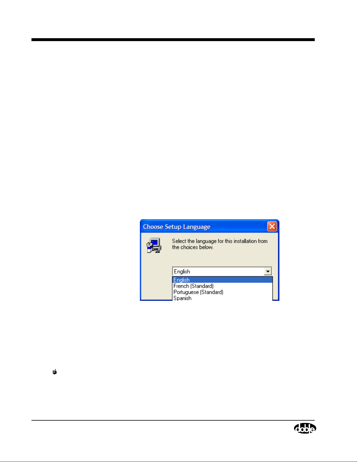
5. Select the language for the installation instructions. After installation, any
of the listed languages can be chosen at any time from the Advanced tab of
the Tools/Configuration window, as long as they have been installed in
step 8 below.
July 22, 2005
Figure 2.1 Language Options
6. The program will ask in which directory to install the M4000 Software. It
is recommended to stay with the default settings. Note that it is different
from the existing version, so that you may use either version on the same
computer. Press the ENTER key.
NOTE Optional Leakage Reactance software must be installed in the same
directory; the optional DTA software may go in its own directory.
7. You will be asked to select some installation options:
2-2 72A-1230 Rev. F
Page 41
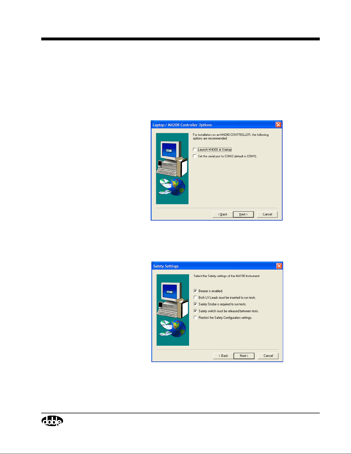
M4000 Insulation Analyzer User Guide
• Launch M4000 at Startup: Select this option if this computer is
dedicated to M4000 tests, since it automatically runs the M4000
program when starting the computer (If you have the icon for the old
version of the software in your startup folder, remove it).
• Set the serial communications port to COM2: select this only if
installing the software on an M4200c controller.
Figure 2.2 M4000 Software Installation Options
8. You will then be asked to select safety options:
Figure 2.3 Safety Settings
• Beeper Is Enabled: Enables the audible warning feature that signals
the beginning of each test (recommended).
July 22, 2005
72A-1230 Rev. F 2-3
Page 42
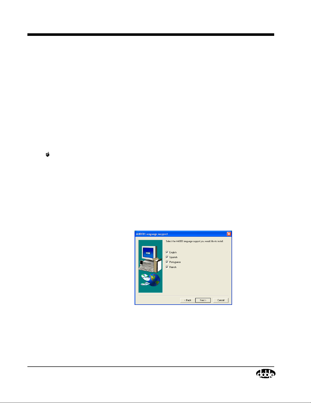
M4000 Software
NOTE Use this last option with care, since if a need arises to change one of the above
• Both LV leads must be inserted to run test: requires that both the
red and blue leads be inserted into the test set to run a test (rarely
used).
• Safety strobe is required to run test: In the event there is a failure of
the strobe bulb or cable, this should be disabled so as to be able to
continue testing without it.
• Safety switch must be released between tests: Serves to discourage
user from artificially holding safety switch down for the duration of
several tests.
• Restrict the Safety Configuration settings: If selected, serves to lock
the above 4 selections so that they cannot be changed from within the
application.
settings (a burnt out strobe light bulb), you cannot change the settings and
continue testing without reinstalling the software.
9. A screen will appear where your company name, as you wish it to appear
in the Nameplate area, can be input. Leave it blank if you prefer to fill the
name in manually each time.
July 22, 2005
10. Finally, you will be asked which languages you wish to have installed on
the computer. You may choose English, French, Spanish, and Portuguese,
and different users may switch among them from the
Tools/Configure/Advanced menu.
Figure 2.4 Languages Installed
11. If using diskettes, insert subsequent disks when prompted and press the
ENTER key.
12. You will be asked if you wish to read the “readme” file.
2-4 72A-1230 Rev. F
Page 43

13. Since you are able to have both the old and new versions on the same
computer, you may wish to be able to switch back and forth at first. To
avoid downloading firmware to the M4100 each time you switch, do the
following:
• Find the M4i.x0, Bootblok.x0, and Loader.x0 files in the directory
where the new version 3.0 is installed (the default is C:\Program
Files\Doble\M4000).
• Copy these 3 files into the directory of the older version you are using.
Installation of the M4000 Software is now complete.
Doble Test Assistant (DTA) Software (Optional)
See instructions found with the DTA software.
Optimization
COM port Setting
M4000 Insulation Analyzer User Guide
Mouse Settings
If the software has been installed on a PC, you may have to adjust the COM
port setting if the wrong choices were made during installation. If you are not
able to run any tests on the M4000, but get a communications error, proceed as
follows:
1. Select Tools/Configuration, and choose the Instrument tab.
2. Set the Serial Port to COM 1.
3. Make sure the baud rate is set to 9600.
4. Click OK, reboot the computer, and try again.
5. If there is still trouble communicating, your laptop may require another
choice. Possible COM port choices are 1, 2, 3, or 4.
Besides the COM port setting, you must be sure no other program is running
that wants to access this same COM port. Review programs located in your
startup folder which start up each time the computer is booted up, and remove
any that may try to grab the COM port. Or, from the System icon in the
Control Panel, go to the Hardware tab and select Device Manager. Disable any
items that require the selected COM port.
You can modify the mouse settings for maximum visibility on the M4200c
Controller:
July 22, 2005
72A-1230 Rev. F 2-5
Page 44

Time/Date Format
• From the Windows “Start” button, choose “Control Panel” from the
“Settings” menu item.
• Double-click on the Mouse Icon, then select the “Motion” tab.
• Click the “Show Pointer Trails box, adjust the scale marker to “Long”
and click OK. This will cause the mouse to leave a trail behind it when
moved, and increase visibility in bright sunlight.
Time/Date Format
You may want to change the time/date format. The default is mm/dd/yyyy for
date, and 12 hour format for time. To change this format, Select “Control
Panel” from the Windows Start button menu. Time and date format can be
changed from the “Date and Time” icon, and this change reflects through to
the M4000.
Introduction to M4000 Software
What’s New
Aside from some behind the scenes changes to make this program a modern
up to date 32 bit program, here are some features visible to the user:
Clipboard 1. The clipboard now has 200 lines instead of 36, so that almost any type of
July 22, 2005
testing should be able to fit in one single file.
2. The M4000 program now supports English, French, Portuguese, and
Spanish.
3. Serial Number and Manufacturer fields have been added to the nameplate
area.
4. The column widths on the test grid are user-configurable.
5. For each test, time, date, air temperature, and humidity are recorded and
can be viewed.
6. A new file structure has been implemented, allowing user-specified file
names for easier data manipulation.
7. The printout now has a grid around the data, for a more professional look.
8. The Clipboard mode now has graphing capabilities (see ”Graphing Test
Results” on page 3-11).
9. The Clipboard mode now offers automatic temperature correction (see
”Temperature Correction” on page 2-12).
2-6 72A-1230 Rev. F
Page 45
M4000 Insulation Analyzer User Guide
Leakage Reactance 10. One Leakage Reactance file can now contain all tests in a series: Three
Phase Equivalent, Per Phase, and tests on different taps. Data entry is now
more intuitive.
External Reference 11. On the External Reference form, both UST and GST tests can be stored all
on the same form.
12. You may now store reversal readings on the same line and automatically
average the results.
13. You may now store test circuit loss associated with the GST test, and the
program will automatically subtract the loss from the test results.
The M4000 Program
To start the M4000 Software: turn on the M4200c Controller; or, if using your
laptop, and the program executable is not in your “StartUp” group:
1. Select All Programs from the Windows Start button menu.
2. Select the Doble Program Group.
Icons
3. Select the M4000 icon.
4. Click the OK button on the “About The M4000 Software” window. You
are now at the M4000 clipboard screen. The menu bar contains a number
of choices, with a row of short-cut icons just below.
July 22, 2005
Before step 4 above, the basic icons shown and their functions are described as
follows:
Icon Description
Open M4000 data file. New M4000 files have the extension
.m4k, but old M4000 files can also be opened using this
command.
Exit the M4000 Software, or select Exit from the File pull
down menu.
72A-1230 Rev. F 2-7
Page 46
Menu Bar
Icon Description
Enter DTA Field System Software, or select DTA from the
Mode pull-down menu. With DTA, the second test mode
available is DTA. See the DTA instruction manual for use of
the DTA option. DTA contains specific forms for different
apparatus types, along with an expert system to evaluate
results. Since this is optional software, this icon will not be
active if DTA software is not installed.
Enter Clipboard Mode or select Clipboard from the Mode
pull-down menu. Without DTA, the only test mode is
Clipboard. The clipboard mode is described further in this
chapter. It provides a generic form for testing any apparatus.
Enter External Reference/Source Mode, or select External
Reference/ Source from the Mode pull-down menu. Since this
is optional software, this icon will not be active if External
Reference software is not installed.
July 22, 2005
Menu Bar
Enter Leakage Reactance Test Mode, or select Leakage
Reactance Test from the Mode pull-down menu. Since this is
optional software, this icon will not be active if Leakage
Reactance software is not installed.
Find help, or press the F1 key, or select the items from the
Help pull-down menu item. Help is described in the 'Using
Help' section of Chapter 1.
The Menu Bar functions are described as follows:
Mode: Allows selection of available test modes. Clipboard is automatically
included with the M4000 software. External Reference/Source, Leakage
Reactance, and DTA are optional software add-ins.
Diagnostics: These help you check the status of the M4000 Insulation
Analyzer, and to diagnose any problems that may exist. See ”Running
Diagnostics” on page 4-21 for a description of this item
View: De-selecting an item from this menu will remove the icon bar from your
screen. Select again to restore it.
Tools : Here you can clear test and nameplate data, view a test note or
temperature/humidity data, or adjust configurations. See the “Configuration”
section in this chapter for a full description of these options.
2-8 72A-1230 Rev. F
Page 47
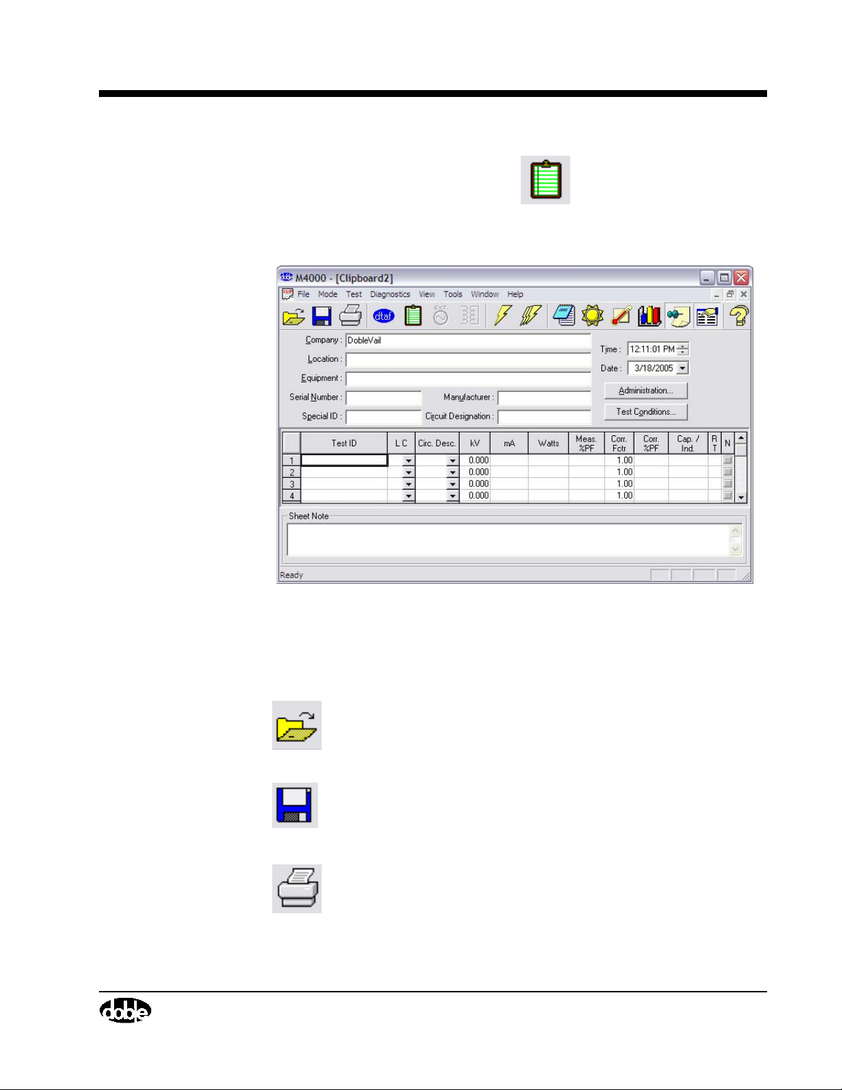
Clipboard Test Mode
To enter Clipboard test mode, click the icon, or select Clipboard from
the Mode pull-down menu item.
The following screen will appear:
M4000 Insulation Analyzer User Guide
Figure 2.5 Clipboard Screen
Clicking on the following icons will perform the described functions:
Icon Description
Open a File. If a Clipboard file is saved, it can be retrieved by
clicking on this icon, pressing F9, or selecting Open from the
File pull-down menu.
Save a File. This can also be done by pressing CTRL+S to
save the file with the existing name, or the F8 key to save with
a new name.
Print the current Clipboard form. This can also be done by
selecting Print from the File pull-down menu item, or by
pressing F7.
July 22, 2005
72A-1230 Rev. F 2-9
Page 48
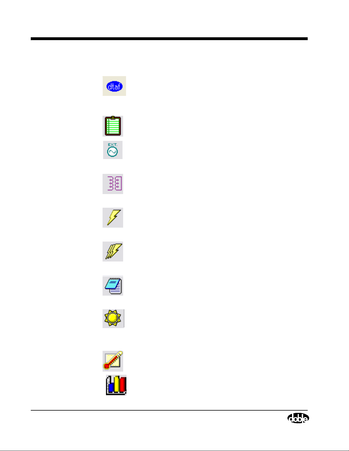
Menu Bar
Icon Description
Enter the DTA Field System program. This can also be done
by selecting DTA from the Mode pull-down menu item.
Click to open a Clipboard screen, where tests may be run and
recorded.
Click to enter External Reference/Source Mode, or select
External Reference/ Source from the Mode pull-down menu.
Click to enter Leakage Reactance Test Mode, or select
Leakage Reactance Test from the Mode pull-down menu.
July 22, 2005
Run a single test. This can also be done by selecting Run A
Single Test from the Test pull-down menu item, or by
pressing F2.
Run a multiple test. This can also be done by selecting Run A
Multiple Test from the Test pull-down menu item, or pressing
FN+F11.
Enter a note. When clicking on this icon, the software will ask
you which line the note corresponds to. The default is for line.
This can also be done by selecting Edit Test Note from the
Edit pull-down menu item.
View the air temperature and percent humidity associated
with each line of test data. This can also be done by selecting
Display Temp./Humidity from the Edit pull-down menu item.
Allows user to activate automatic temperature correction
function for the clipboard test mode.
Graph the selected clipboard results
2-10 72A-1230 Rev. F
Page 49
M4000 Insulation Analyzer User Guide
Icon Description
Toggle sheet note. Click this icon to display or hide a note
area for the entire clipboard sheet at the bottom of the screen.
Toggle Nameplate. Click this icon to display or hide all but
the test data. This allows the user to hide or display the
Nameplate information, time, date, Administration and Test
Condition buttons.
About M4000 For Windows. This can also be chosen by
selecting About M4000 For Windows from the pull down
menu item.
NOTE If you are using the pull-down menus and wish to remove these icons,
click on the View pull-down menu item and then click on Toolbar. This
will disable the icons. They can be retrieved by repeating the same action.
Menu Items
Mode Menu
Test Menu
The menu items are File, Mode, Test, Diagnostics, View, Tools, Window,
and Help. The principal functions included under these items are better
accessed by using the icons described in the previous paragraphs. The features
under what used to be the Edit menu are now found under Tes t by selecting
the Clear menu item. The Diagnostics commands are described in Chapter
Six, M4100 Instrument.
Select the type of test desired. Choices are:
• Clipboard (for Power Factor, Exciting Current tests)
• Leakage Reactance (Requires optional software)
• External Reference/Source (Requires optional software)
• DTA (Requires optional software)
This menu contains the start single test (F2) and start multiple tests (F11)
commands.
July 22, 2005
72A-1230 Rev. F 2-11
Page 50

Diagnostics
Diagnostics
View Menu
Tools Menu
July 22, 2005
This menu contains several self-test options, described in ”Running
Diagnostics” on page 4-21.
Commands here allow display or hiding of the:
• Toolbar (row of icons)
• Status Bar (along the bottom of the screen, it includes status of the
Caps Lock and Num Lock functions, which should be off)
• Nameplate data fields
• Sheet note located just above the Status bar at the bottom of the screen.
This menu includes the following:
• Insert a test line command, inserts a new row above the row in which
the cursor sits.
• Remove an empty test line removes the empty line on which the cursor
sits. If the line is not empty, a warning message appears.
• Clear command for test results, nameplate data, test note, and sheet
note
• Test Note command, which allows access to individual test notes for
each line of test data
• Temp and Humidity command, which allows access to the
temperature and humidity readings for each line of test data.
• Temperature Correction, as described below, enables the user to select
the type of apparatus under test so as to activate automatic temperature
correction.
• Graph results command, allowing the user to select test results on the
clipboard and graph them.
• Configuration settings for both the software and the instrument,
described under ”Configuration” on page 2-13.
Temperature Correction
To activate automatic temperature correction:
1. First, run your tests and fill in the rows with the results.
2-12 72A-1230 Rev. F
Page 51
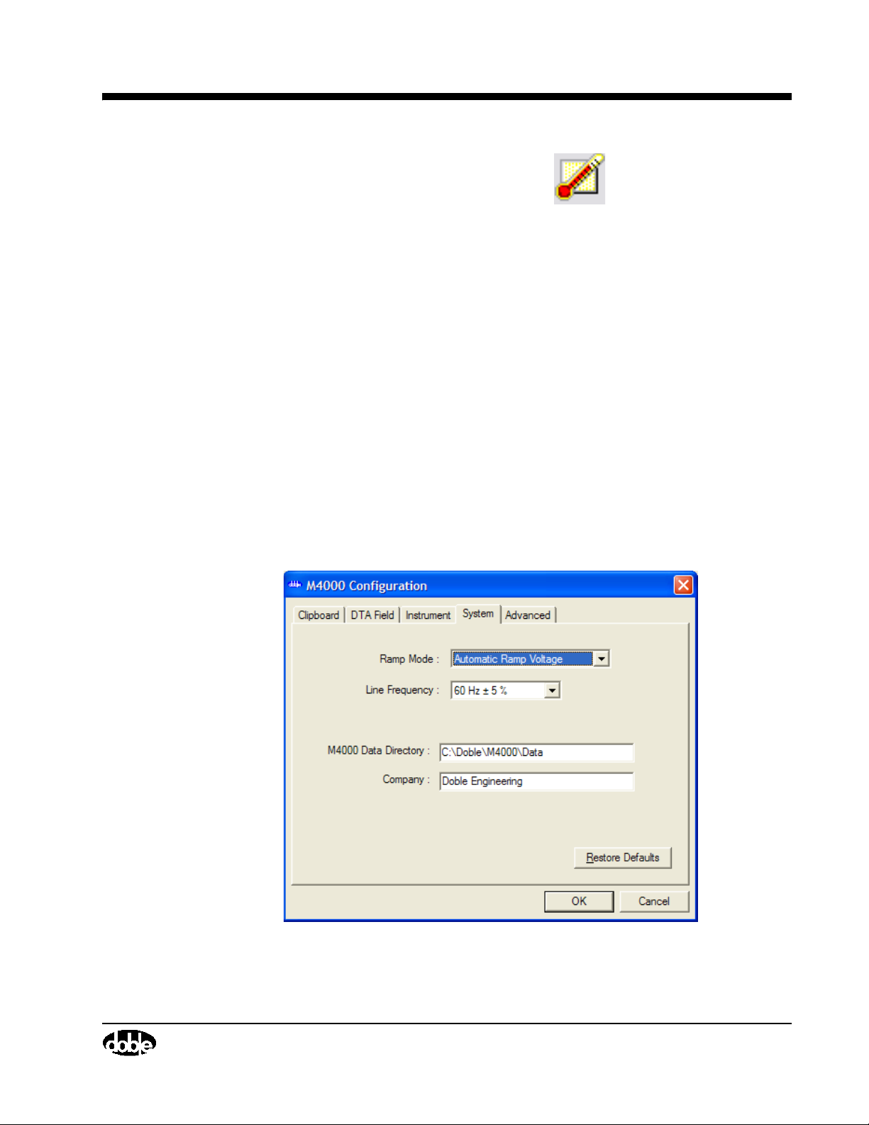
Configuration
M4000 Insulation Analyzer User Guide
2. Click the temperature correction icon , or select Temperature
Correction from the Tools menu.
3. In the Temperature Correction window, fill in the rows on the clipboard
screen to which you wish to apply the temperature correction. These rows
must have temperature data associated with them for this function to work.
4. Select the Equipment Type and Sub-types where applicable.
5. Click OK, and Clipboard will apply the appropriate correction factor to the
selected rows of test data.
There are five option tabs available in the M4000 Configuration window,
accessed from the View menu item. They are System, Clipboard, DTA,
Instrument, and Advanced.
System Configuration
When selecting the System tab, the following appears:
July 22, 2005
Figure 2.6 M4000 System Configuration
72A-1230 Rev. F 2-13
Page 52

Clipboard Configuration
Ramp Mode - Auto Ramp Mode raises the voltage automatically at a rate
selected separately in the Clipboard Configuration and DTA Configuration.
Manual Set Voltage allows raising the voltage by pressing the PGUP key to
raise the voltage rapidly, the PGDN key to lower the voltage rapidly, the up
arrow key to raise the voltage slowly, and the down arrow key to lower the
voltage slowly. The rates at which the voltages are raised and lowered
manually are selected separately in the Clipboard configuration and the DTA
Configuration.
Line Frequency - Select the frequency that corresponds to the user's system;
or, if trying to duplicate a test result made at another frequency, select either
frequency. Under normal system conditions, make the ± 5% selection. If your
power line frequency is itself experiencing this degree of variation, you may
be required to make the ± 10%
selection to avoid the effect of electrostatic
interference. The M4000 users Line Frequency Modulation to measure above
and below power line frequency to avoid measurement of electrostatic
interference.
M4000 Data Directory - This is the directory in which the Clipboard data is
to be stored. To change the default settings, use the mouse to click into the
M4000 Data Directory field. Then, edit the settings to reflect in which
directory the Clipboard data is stored.
July 22, 2005
Clipboard Configuration
Select a directory other than C:\DOBLE\DTA for data storage for both
Clipboard data and DTA data.* Click on the OK button to accept your
changes.
* For example, use C:\Doble\DTA\DATA.
Company: If filled in, this line will cause all tests to use the information in the
“Company” field when starting a new clipboard test.
When selecting the Clipboard tab, the following appears:
2-14 72A-1230 Rev. F
Page 53
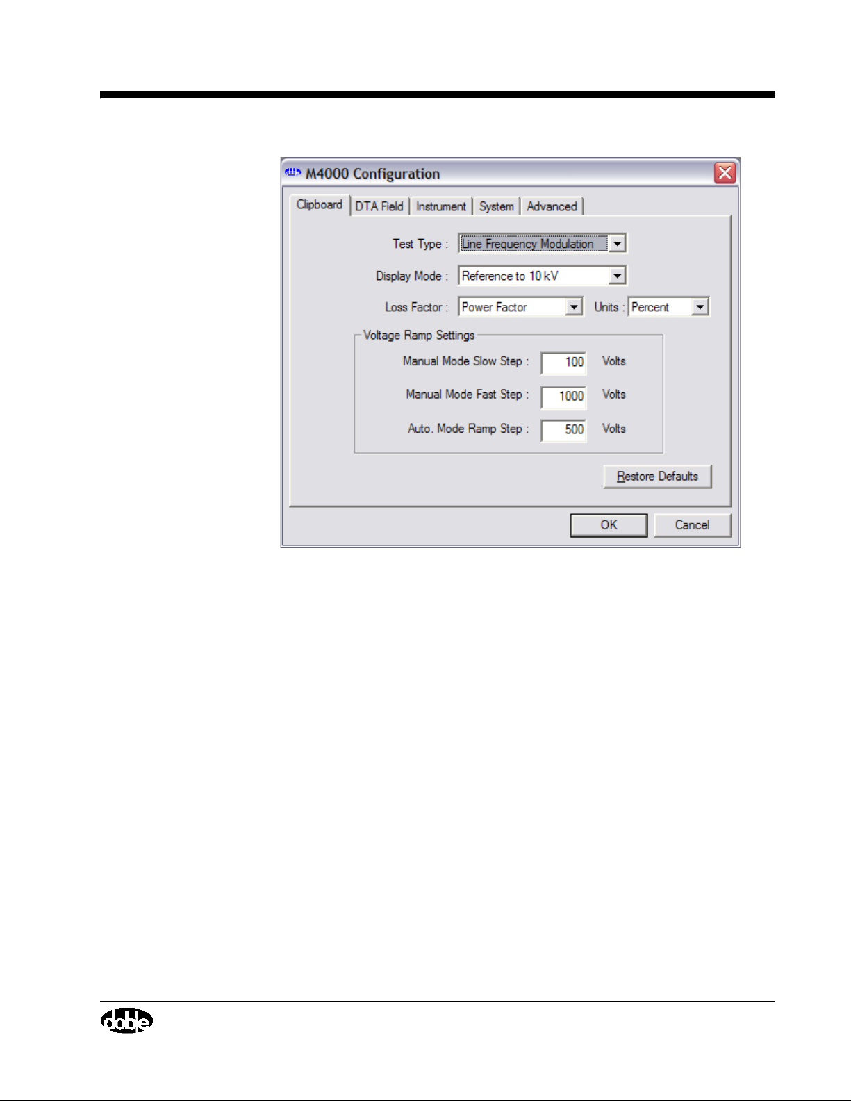
M4000 Insulation Analyzer User Guide
Figure 2.7 Clipboard Configuration
Test Typ e - If Line Frequency Modulation is selected, a test at ± 5% of the
reference frequency, will be performed. This selection is desirable when
testing in the presence of electrostatic interference. If Line Sync Reversal is
selected, a test at the positive polarity and a test at the negative polarity in
reference to the input voltage at the base frequency is performed. This
selection is desirable when performing tests using a resonator or exciting
current tests on a transformer.
Display Mode - If Reference to 10 kV is selected, all results will be reported
as if 10 kV were the applied voltage. If results obtained were tested at 2 kV,
current and watts measurements will be multiplied by 5. Historically, this is
the way all Doble tests have been performed. If Actual Values are selected, all
results will be reported in reference to the applied voltage.
July 22, 2005
72A-1230 Rev. F 2-15
Page 54

DTA Field Configuration
July 22, 2005
Loss Factor - There are two options available, Power Factor and Dissipation
Factor, practically identical in routine usage. Dissipation Factor may be
chosen when the user wishes to duplicate nameplate data from international
manufacturers. However, the two are virtually identical at Power Factor
readings below 5%. Units may be selected as Percent or Actual (and, for
Dissipation Factor, mW/VAr). Power Factor is generally expressed in percent,
and Dissipation Factor as Actual.
Voltage Ramp Settings - The rate of voltage change corresponding to the
Auto Ramp Mode and Manual Set Options is entered in these fields. For
example, the default settings call for an increase of 100 volts every time the up
arrow is pressed when manually bringing up the voltage.
• Manual Mode Slow Step - The increment of voltage corresponding to
each press of the up and down arrow key for manually setting the
voltage. To change the default settings, click the mouse in this field
and enter the desired voltage.
• Manual Mode Fast Step - The increment of voltage corresponding to
each press of the PGUP and PgDn key for manually setting the
voltage. To change the default settings, click the mouse in this field
and enter the desired voltage.
• Auto Mode Ramp Step - The increment of voltage corresponding to
the automatic voltage ramping steps. Using the default setting means
that the voltage is raised and lowered in 500 volt increments. In the
Auto Ramp Mode, voltage is lowered when a reversal is performed.
Click on the OK button to accept the selections.
DTA Field Configuration
This only applies to users of DTA Field System Software. When the DTA
Field Configuration tab is selected, the following appears:
2-16 72A-1230 Rev. F
Page 55
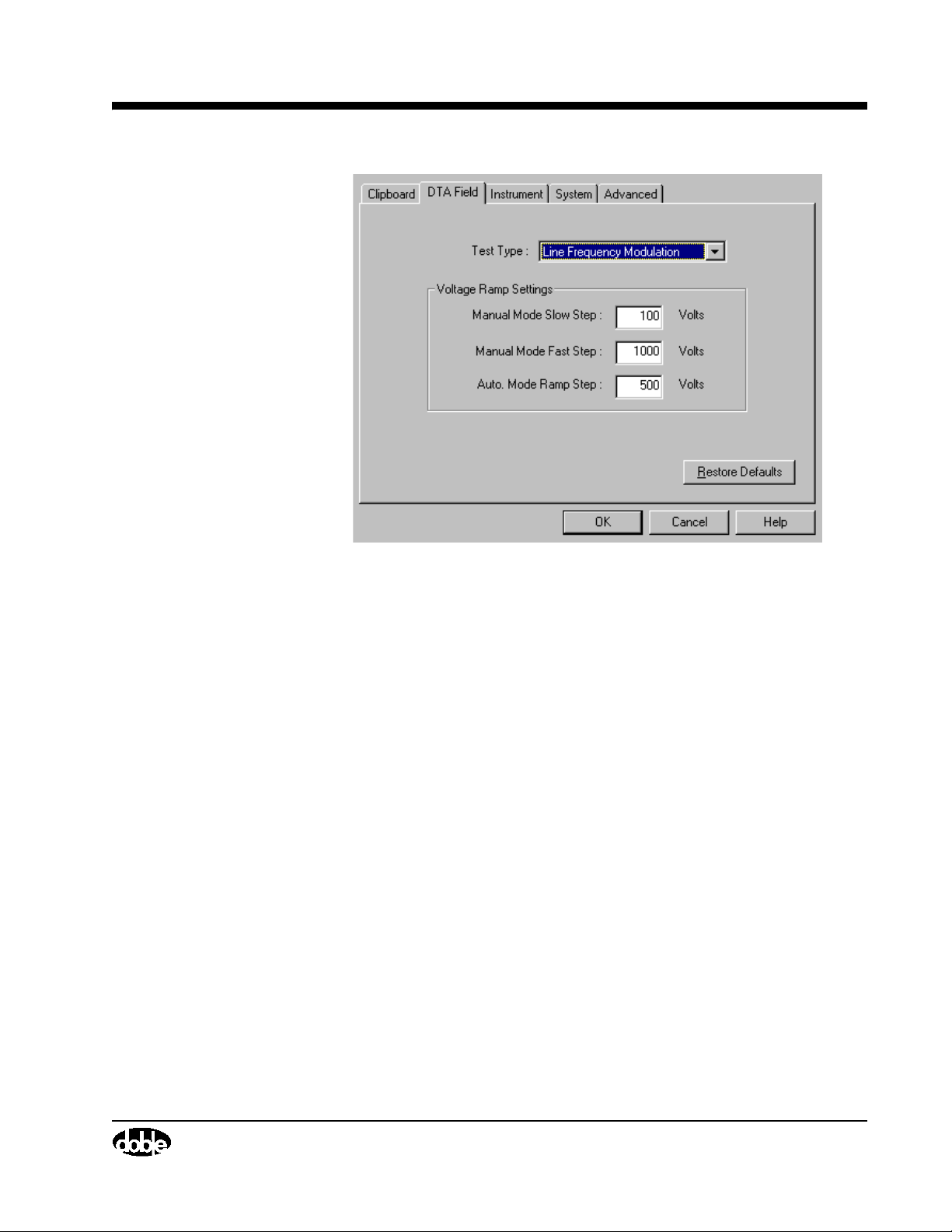
M4000 Insulation Analyzer User Guide
Figure 2.8 DTA Configuration
Test Typ e - See Clipboard Configuration for a description of this item.
Voltage Ramp Settings - See Clipboard Configuration for a description of
this item.
July 22, 2005
72A-1230 Rev. F 2-17
Page 56
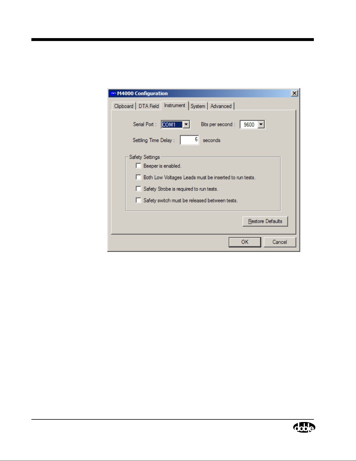
Instrument Configuration
Instrument Configuration
When the Instrument Configuration tab is selected, the following appears:
July 22, 2005
Figure 2.9 Instrument Configuration
Serial Port - It may be necessary to change this setting to accommodate
laptops being used with the M4100. The M4200c uses COM2, and laptops
usually use COM1. The “bits per second” setting should not be changed from
the default 9600.
USB Converter- If using a Serial to USB converter to utilize a USB port on
your laptop for connection to the M4100, check your PC settings to obtain the
comport that has been set by the converter. For Windows XP, go to the Start
button, select Control Panel/System (or alternately, right-click My Computer
and select Properties), then click Hardware and then Device Manager. Click
the plus sign next to Ports (Com & LPT) to see the comport assigned to your
converter.
2-18 72A-1230 Rev. F
Page 57

M4000 Insulation Analyzer User Guide
Settling Time Delay- The time, at maximum test voltage, during which the
M4000 samples the data. If it appears that excessive electrostatic interference
is affecting test results, the settling time may be increased in order to sample
the data over a longer period of time. To change the value in this field, click
the mouse in this field and enter in a new value.
Safety Settings - These may be set as desired, provided the option “Restrict
the Safety Configuration settings” was not set during software installation.
If it was, and you want to change these settings, you will have to re-install the
software and de-select that option. It is recommended that unless they are not
functioning, the user should leave the beeper and strobe light operational. The
settings are:
• Beeper - If the beeper is enabled, four beeps will sound when voltage
is applied to a specimen. If the beeper is disabled, there will be no
audible warning of applied voltage.
• Both Low Voltage Leads must be inserted to run test - it is
recommended this box be left unchecked, since most tests require only
one lead.
• Safety Strobe required to run test- If “required to run a test” is
selected, the strobe must be plugged in or a test cannot run. If the
strobe is not available, select “not required”.
• Safety switch must be released between tests - Prevents users from
defeating the purpose of the safety switch by artificially holding it
shut. The switches should be pressed when the message onscreen tells
you to.
July 22, 2005
Click on the OK button to accept your selection.
Advanced Configuration
When the Advanced tab is selected, the following is displayed:
72A-1230 Rev. F 2-19
Page 58

Advanced Configuration
July 22, 2005
Figure 2.10 Advanced Configuration
Language: Choose from English, French, Spanish, and Portuguese, if selected
for installation.
Filter Type: The default is Slow, and should not be changed without
consulting Doble.
Capacitor Model: The default is Parallel, and should not be changed without
consulting Doble.
Inductor Model: The default is Parallel, and should not be changed without
consulting Doble.
Allow Multiple Documents: If this box is checked, more than one set of test
data can be active and displayed at once.
Current Range: The default is Auto, and should not be changed without
consulting Doble.
Watts Range: The default is Auto, and should not be changed without
consulting Doble.
Grid Font Size: Allows you to increase the size of the fonts on your screen,
making it easier to see the data.
Print Font Size: Increases the size of the font used in printing.
2-20 72A-1230 Rev. F
Page 59
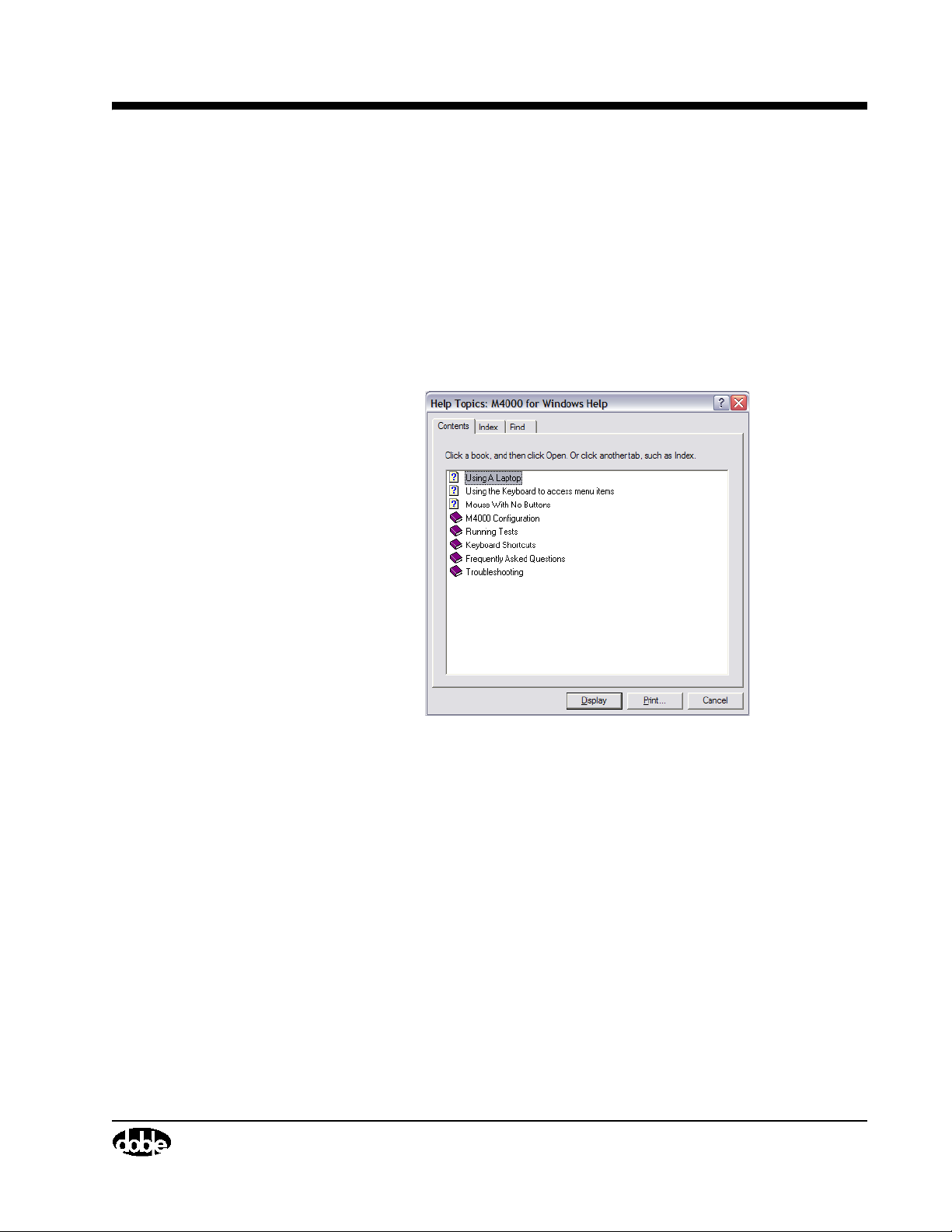
Using Help
Contents
M4000 Insulation Analyzer User Guide
When Help is selected, two options are presented:
1. Contents F1.
2. About M4000 For Windows...
The Help/Contents option opens the Help window:
Figure 2.11 Help Window
When Contents is selected, you can find how to use Help by pressing F1. The
contents screen also has a series of buttons along its top:
The Glossary button has topics that are specific (such as, Auto Mode
Ramp Step).
If you are unsure which item to select, you can use the Search function
located on the top of the Help screen to find a specific topic.
To return to the previous screen, press Back located on the top of the Help
screen.
To view each item in the list of contents, press the >> button. To go back to
the Help of the previous item, press << button.
July 22, 2005
72A-1230 Rev. F 2-21
Page 60
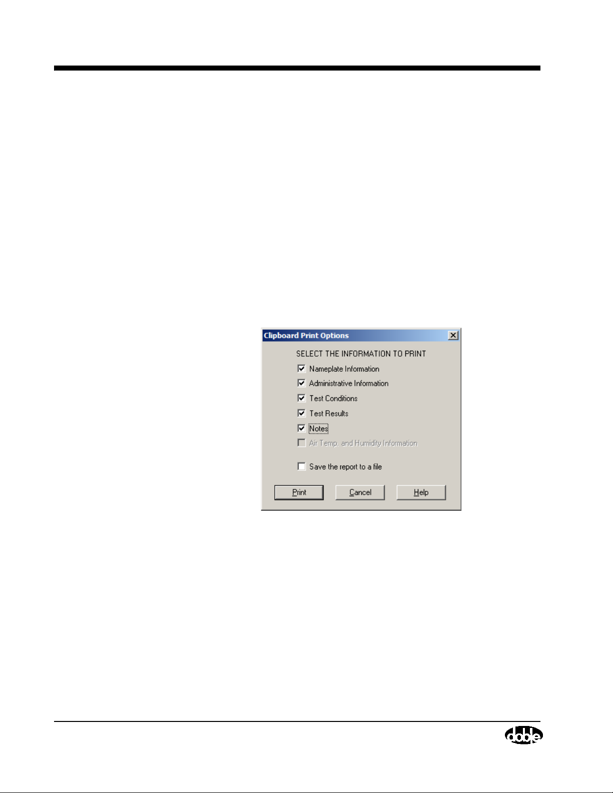
About M4000 For Windows
About M4000 For Windows
Selecting this item displays the current version of M4000 Software and
firmware.
Printer Setup
The default printer setting for your M4200c Controller is for a thermal printer.
This enables the use of the M4200c Controller's built-in printer. If using a
laptop, you must use Windows to add in the necessary printer drivers for your
office printers.
Printing
To print a Clipboard form, select Print from the file pull-down menu item, or
press F7. The following screen will appear:
July 22, 2005
Figure 2.12 Clipboard Form Report Generator
To print a field, select it by clicking on the square, adding a a checkmark. To
print to a file, select “Save the report to a file” by clicking its box, adding a
checkmark. Results can be saved in text (txt) or comma separated variable
(csv) format.
A detailed description of each of these fields can be found in ”Entering
Clipboard Information” on page 3-1.
2-22 72A-1230 Rev. F
Page 61
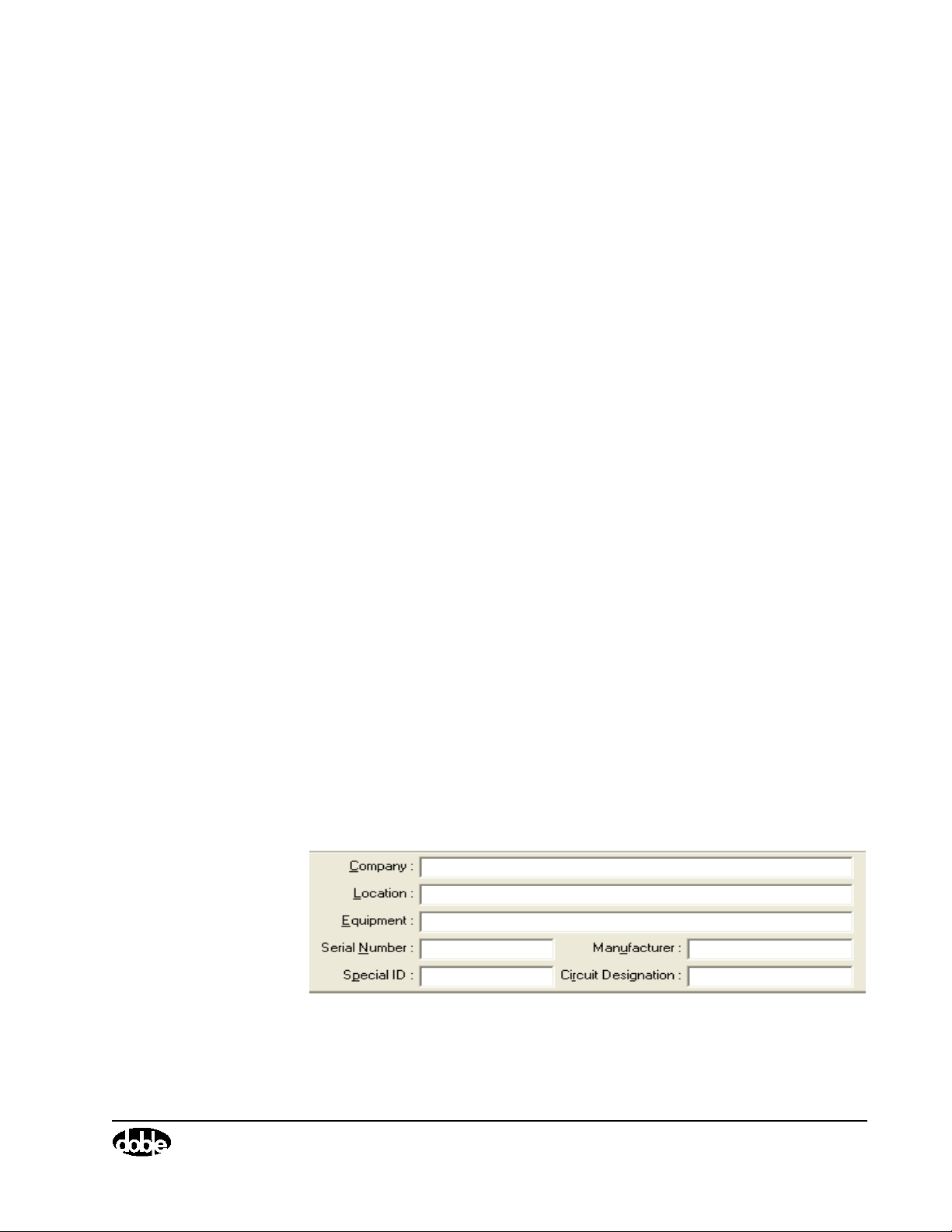
3. Running M4000 Tests
There are four test modes available with the M4000 software; all but
Clipboard require optional software:
• Clipboard Mode
This is a generic form for recording and storing test results, nameplate
information, weather conditions, test parameters, and notes, and is
described below. A new graphing function allows test results to be
graphed.
• External Reference/Source Mode (page 3-12)
This test mode enables the user to perform tests using an external
source and reference, extending the range of test voltage above the 12
kV of the M4000 test set.
• Leakage Reactance Mode (page 3-16)
This test mode enables the user to measure transformer leakage
reactance. Auxiliary hardware is required in the form of the M4110
Leakage Reactance Interface, or the M4130 Leakage Reactance
Module.
• DTA Mode (page 3-17)
July 22, 2005
Entering Clipboard Information
Nameplate Information
Within the Clipboard form, the following is what is considered nameplate
information:
72A-1230 Rev. F 3-1
Figure 3.1 Nameplate Information
Page 62
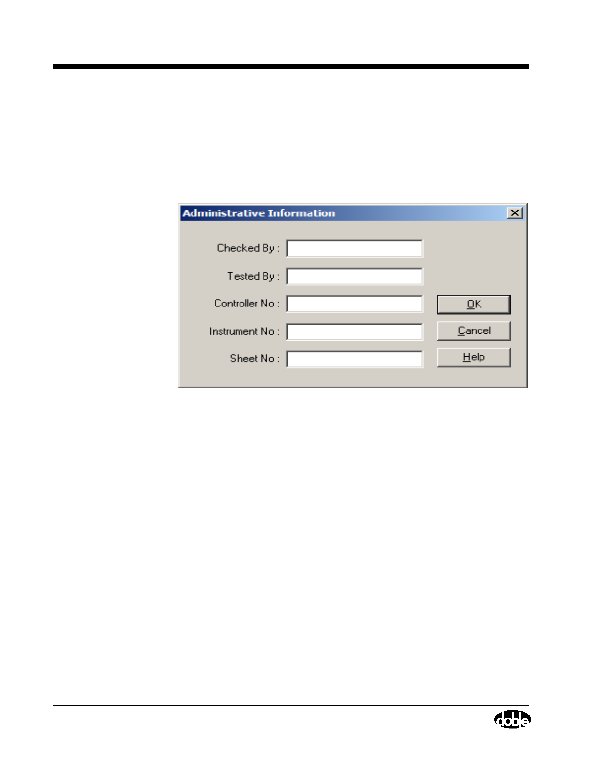
Administrative Information
Entering this information is vital to properly identify the test and the
equipment tested.
Administrative Information
Next to the Nameplate Section is an Administration button. When clicking this
button, the following screen will appear:
July 22, 2005
Figure 3.2 Administrative Information
The following is an identification of these terms:
Checked By The person who checked the results (if different from
the user).
Teste d By The user of the M4000 Insulation Analyzer.
Controller No. The serial number is located on the bottom of the
M4200c Controller.
Instrument No. The serial number is located on the front panel of the
M4100 Instrument.
Sheet No. Identification for each single Clipboard Form is done
with filenames when saving the form. Sheet number
was a form of identification used on older paper test
forms and the space is provided if the user needs to use
it to further identify the test.
After entering this information, click on the OK button to save it.
3-2 72A-1230 Rev. F
Page 63
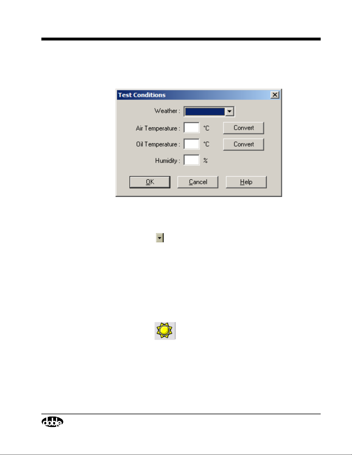
Test Conditions
M4000 Insulation Analyzer User Guide
Clicking on this button will show the following screen:
Figure 3.3 Test Conditions
The Weather is a pull down menu item with the selections accessed by
clicking on the (down arrow icon).
Entering Air Temperature and Humidity is unnecessary if using the
Temperature Probe. If not, it is necessary to enter data in each field. In either
case, Oil Temperature is required if testing oil-filled equipment. For
transformers, use the top oil temperature.
Click on a Convert button first to enter the temperature in Fahrenheit.
Clicking the OK button will save the entries.
In the Clipboard mode, each row of test data contains the Test Conditions
information. Test conditions for all the tests on the clipboard form can be seen
by clicking the icon, or selecting To ols/ Te mp. a n d Hum i dity. The
data found on the Test Conditions screen is that of the last test run.
July 22, 2005
72A-1230 Rev. F 3-3
Page 64

Test Conditions
Test Results Information
Each line of the Clipboard test results contain the following fields:
Column Description
No name... Number – indicates the test line (row) number. There are
TEST ID Test Identification – on each test line, you can enter a
LC Line Configuration – To get an explanation of the letter
Circuit Desc. Circuit Description – the abbreviation in this column
36 rows, accessible by scrolling down with the down
arrow key.
serial number or description of the test to be performed.
displayed in this column, click the “?” on the icon bar.
Clicking on the will display the pop-up list of choices.
defines the test circuit used when performing a test on a
line of the Clipboard Form. Clicking on the will
display a pop-up window of all the choices. Select the
desired choice. See “Test Modes Of The M4000
Analyzer, in the Doble Test Procedures manual.
July 22, 2005
kV Kilovolts – this column indicates the test voltage, in
thousands of volts, to be used during the test (for
example, 10.00 means 10,000 volts).
mA Milliamperes – this column contains the specimen test
current results in milliamps. You cannot enter or make
changes in this column. The results are recorded after
pressing F5 to accept results of a test.
Watts Watts – this column contains the specimen watts loss test
results in watts. You cannot enter or change results in
this column. The results are recorded after pressing F5 to
accept results of a test.
Meas%PF Measured Percent Power Factor. This column contains
the calculated percent power factor from the
Milliamperes and watts loss results obtained from the
test. You cannot enter or change results in this column.
3-4 72A-1230 Rev. F
Page 65

M4000 Insulation Analyzer User Guide
Column Description
Corr. Fact. Temperature Correction Factor. This column includes
automatic application of temperature correction factors
to the Clipboard Form. The default correction factor is
1.00.
The Measured Percent Power Factor is multiplied by this
Temperature Correction Factor to obtain the Corrected
Percent Power Factor in the column to the right of the
Corr. Fact. Column. See ”Temperature Correction”
on page 2-12 for this automatic function.
Corr%PF Corrected Percent Power Factor. In this column, you will
find the results of the Measured Percent Power Factor
Times the Correction Factor. You cannot enter or change
results in this column.
Cap. /Ind. Capacitance/Inductance. Whether the current is
capacitive or inductive is displayed in this column. You
cannot enter or change results in this column.
RT Rating. You may enter a one letter rating (G. B. I., etc.)
of the insulation in this column.
N Note. If a note is entered for a single line, a check mark
will show in this box. A test note is entered by selecting
Test N ote. .. from the Tools pull-down menu item, or by
clicking on the notepad icon. You will be asked to which
test line the note corresponds. The default test line is No.
1.
To enter a note that relates to the entire Clipboard Form,
type in the area at the bottom of the screen titled, Sheet
Note (If it is hidden, click Sheet Note from the View
menu).
To clear a note, select Clear from the Tools pull-down
menu item.
July 22, 2005
72A-1230 Rev. F 3-5
Page 66
Test Conditions
Running Single and Multiple Clipboard Tests
Either single or multiple tests (up to six at once) may be run. Each row or line
of the test form represents one test, and for each test, the following
information should be entered into the appropriate columns:
•Test ID
• Line Configuration (LC); the default value: A, Reference to 10 kV,
Line Frequency Modulation, 60 Hz, is the most common (use B for a
50 Hz test). Use C, Reference to 10 kV, Line Sync Reversal, for
testing with a resonator or for excitation current tests, regardless of
system frequency.
• Circuit Description (GST-Ground, GST-Guard, UST)
•Test kV
The above information may be entered before initiating a test. Or, a test may
be initiated immediately, and you will be prompted to enter the line number,
Line Configuration, Circuit Description and Test kV.
July 22, 2005
To run a single test, press F2, or click the icon.
To run multiple tests (up to six), press FN+F11 or click the icon.
3-6 72A-1230 Rev. F
Page 67
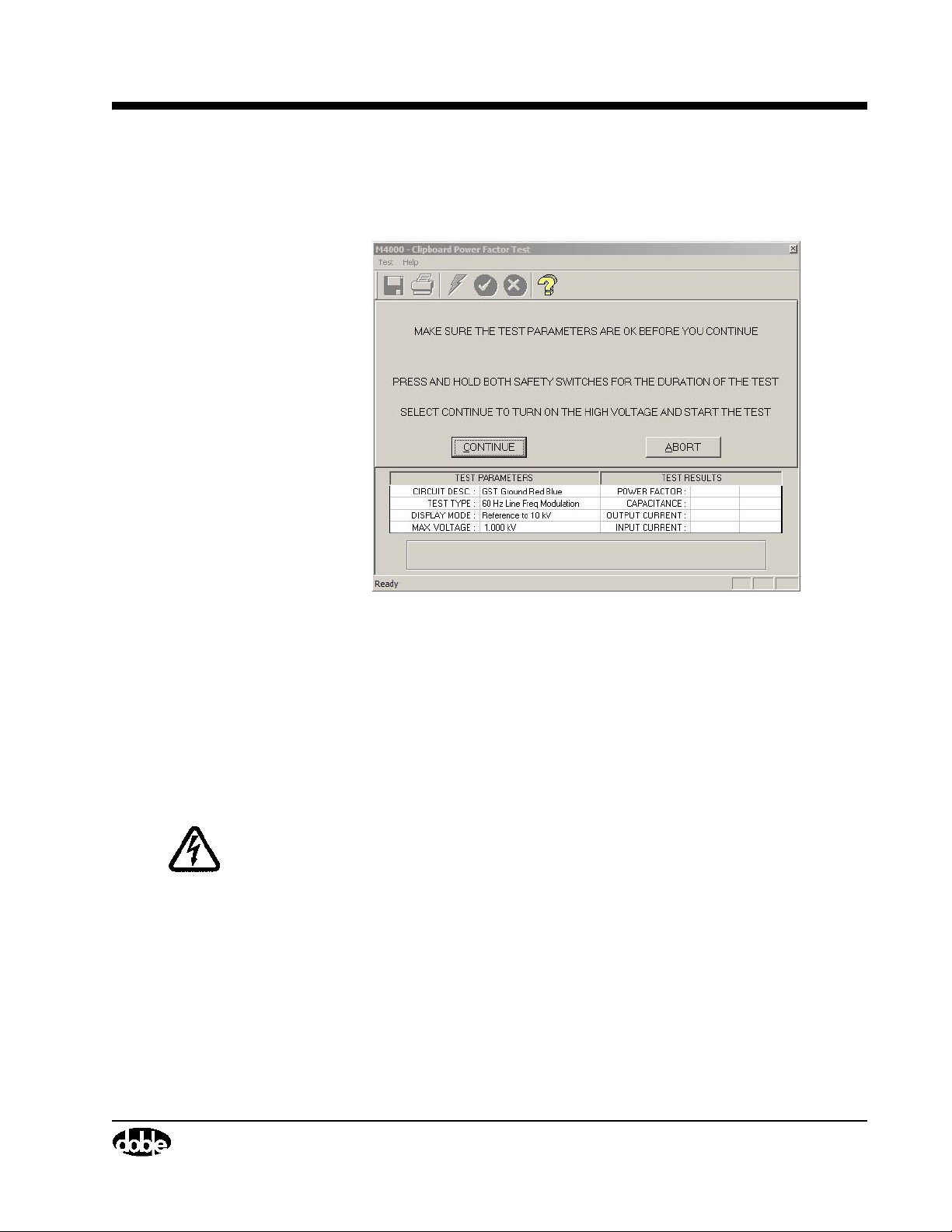
Raising Test Voltage
M4000 Insulation Analyzer User Guide
After making the necessary entries, the following screen appears:
Figure 3.4 Safety Screen
This screen shows the parameters that will be used when the test is run.
Double-check the cable connections and test parameters. If the test parameters
are not correct, click on the Abort button or press the ESC key.
When the parameters are correct, proceed with the test by depressing both
safety push buttons, and either pressing the ENTER key or clicking on the
Continue button.
WARNING High voltage will be present after starting the test. Pressing the ESC key
or F4, or releasing a safety push-button, will turn off the high voltage.
The following screen will appear:
July 22, 2005
72A-1230 Rev. F 3-7
Page 68
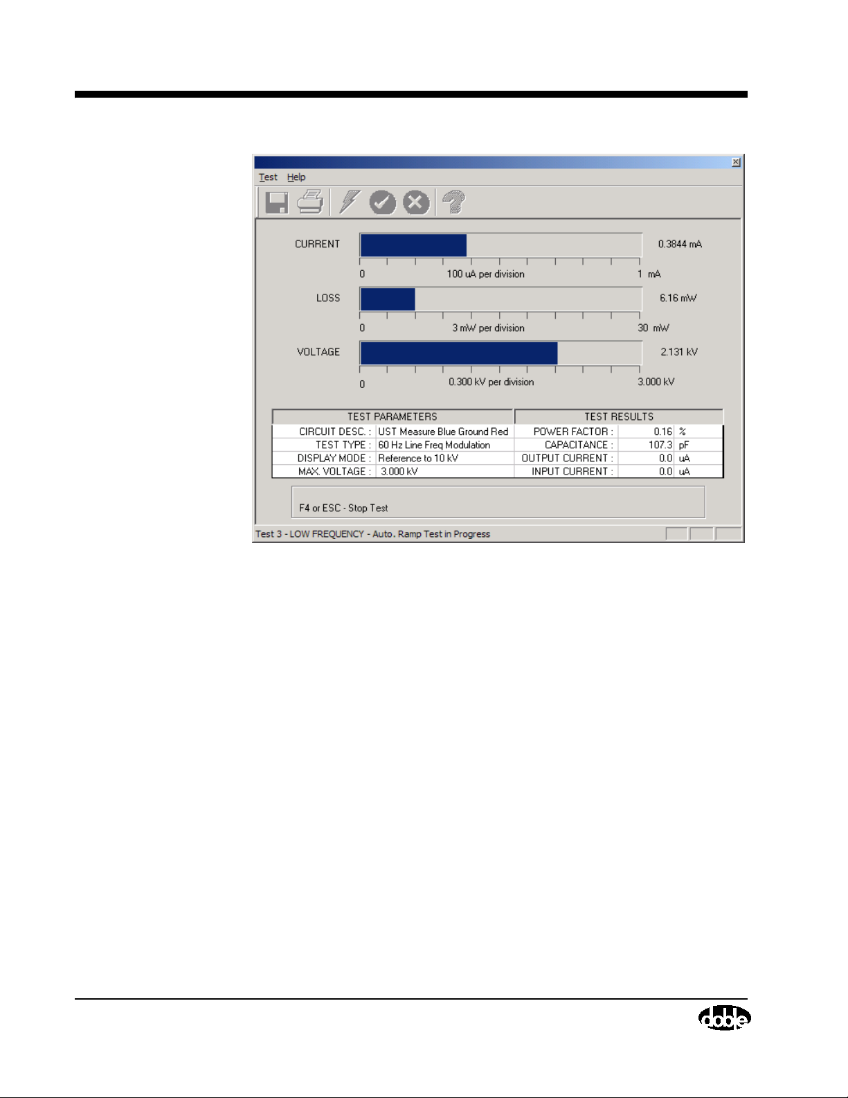
Test Results
July 22, 2005
Test Results
Figure 3.5 Test in Progress
The test will proceed automatically if Auto Ramp Mode is selected in the
Clipboard Configuration, or will be ramped up by the operator if Manual Set
Voltage is selected in the Clipboard Configuration. The digital values for these
parameters will be shown to the right of the meters. The table on the screen
describes test conditions and power factor test results. The line on the bottom
of the screen displays the status of the test. When running multiple Clipboard
tests, the line number of the test that is running will be displayed on the same
line. For each test line, the voltage will ramp to the required maximum test
voltage twice. This is required to implement the selected electrostatic
interference cancellation technique (Line Synchronized Reversal or Line
Frequency Modulation).
After the test is completed, the following appears:
3-8 72A-1230 Rev. F
Page 69
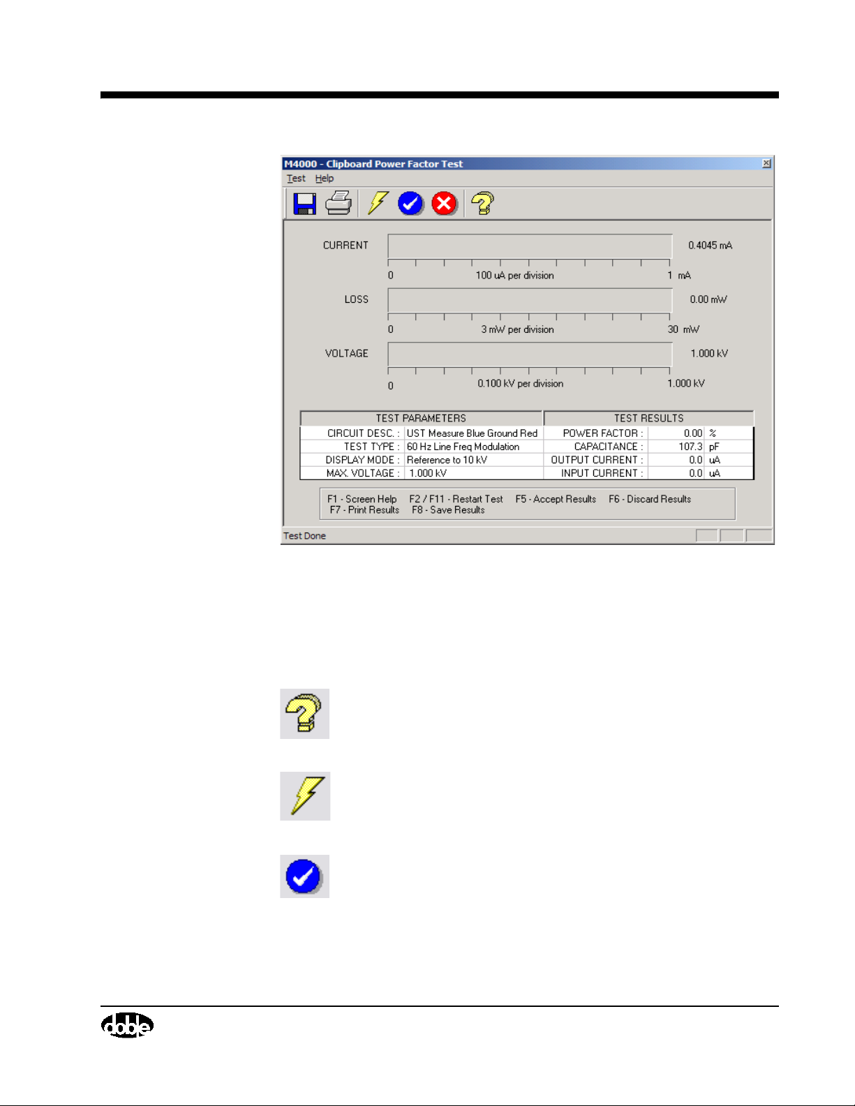
M4000 Insulation Analyzer User Guide
Figure 3.6 Test Complete
There are choices listed at the bottom of the screen. An explanation of each
key's function is as follows:
Icon Description
Pressing F1 will display “Screen Help” which is also available by
clicking on this icon.
Pressing F2 or FN+F11 will “Restart Test”, also available by
clicking on this icon.
Pressing F5 will “Accept Results” of the test(s) successfully
performed, return to the Clipboard Form, and copy the results into
the proper columns. When performing multiple tests, only tests
completed prior to a stopped test will be accepted into the
Clipboard Form. This is also available by clicking on this icon.
July 22, 2005
72A-1230 Rev. F 3-9
Page 70
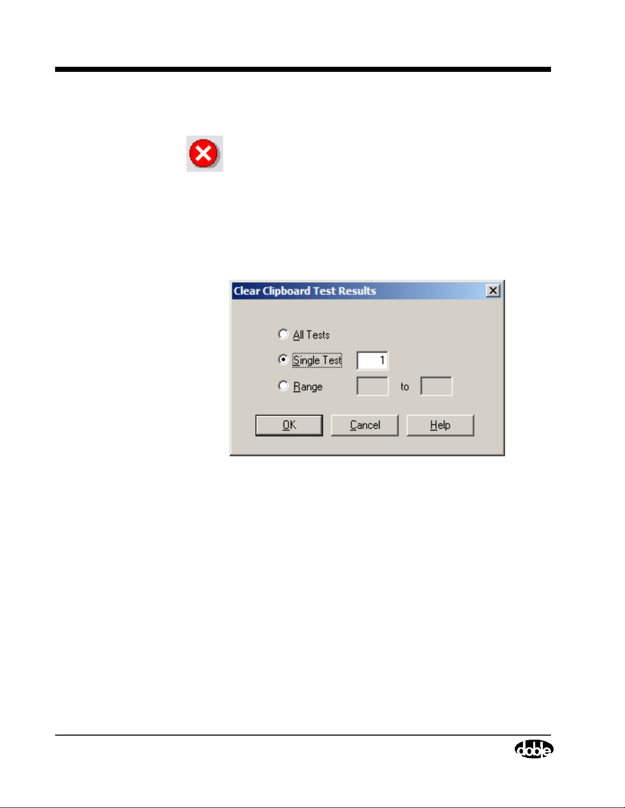
Clearing Test Results
Clearing Test Results
Icon Description
Pressing F6 will “Discard Results” and returns you to the
Clipboard Form. This is also available by clicking on this icon.
After acceptance of tests, you can clear the test results by selecting Clear/Test
Results from the Too ls pull-down menu item, or, by pressing F10. When this is
done, the following screen appears:
July 22, 2005
Figure 3.7 Clear Test Results
You have the option to clear all tests, clear a single test line, or clear multiple
test lines.
3-10 72A-1230 Rev. F
Page 71
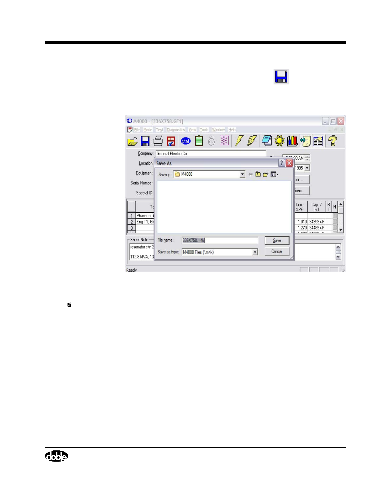
Saving Test Results
M4000 Insulation Analyzer User Guide
To save the nameplate and clipboard data, select the icon, or the Save
As... item under the File menu. You will be prompted to select a file name.
You may save in the selected folder (typically C:\doble\dta\data).
NOTE As you add tests in Clipboard, you may want to periodically save the file
Graphing Test Results
July 22, 2005
Figure 3.8 Saving Clipboard
to include added test data. All 200 lines may be saved under a single file
name. But after saving with a given file name the first time, all subsequent
saves with the same name will result in the message, “This file already
exists. Do you want to replace it?” Select the “Yes” button, or the new
data will be not be saved. However, if the Serial Number or Special ID
fields have been edited since the last save, the filename, which is based on
one of these two fields, will have changed and the file will be saved based
on the new filename. Once all 36 lines are filled with data, save it one last
time. Then, to continue, you must clear the data and start a new file name.
With the new graphing function, you can graph data on the clipboard sheet.
1. Run a test or open a file, placing data on the clipboard.
2. Select the test data you wish to be graphed.
72A-1230 Rev. F 3-11
Page 72
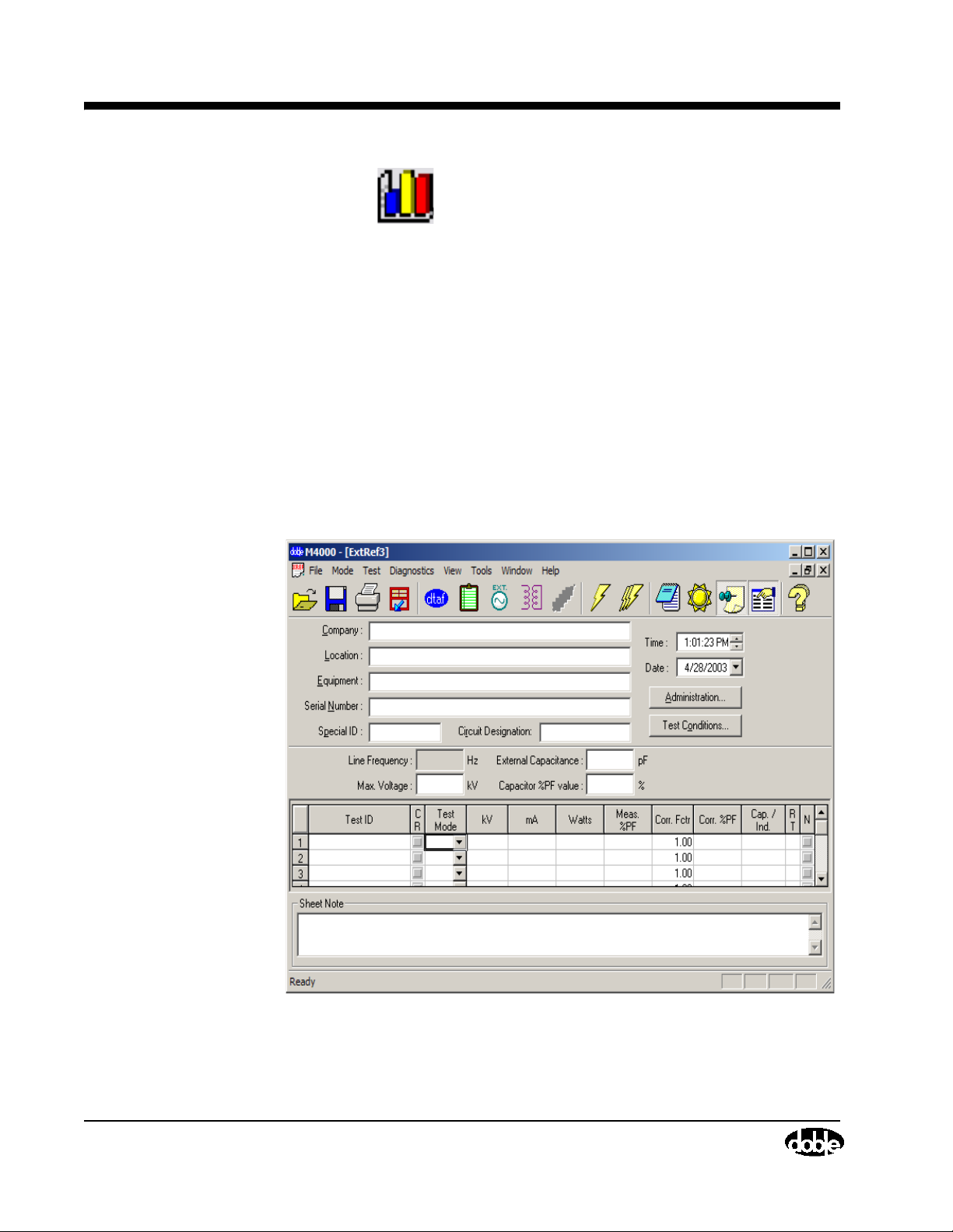
Running A UST Test
3. Click the icon. In the pop-up window, select whether you want a
Histogram or a Trend.
4. If a Histogram is chosen, select the value you wish to plot. In Bins, select
the number of ranges you wish to use to categorize your data, then click
Draw.
5. If a Trend is chosen, select values to plot on the X and Y axes, then click
Draw.
6. After you have drawn the graph, there are several icons along the top you
can select to change the type of graph, or to refine it’s appearance.
External Reference/Source Test (Optional Software)
Running A UST Test
July 22, 2005
Figure 3.9 External Reference Main Screen
3-12 72A-1230 Rev. F
Page 73
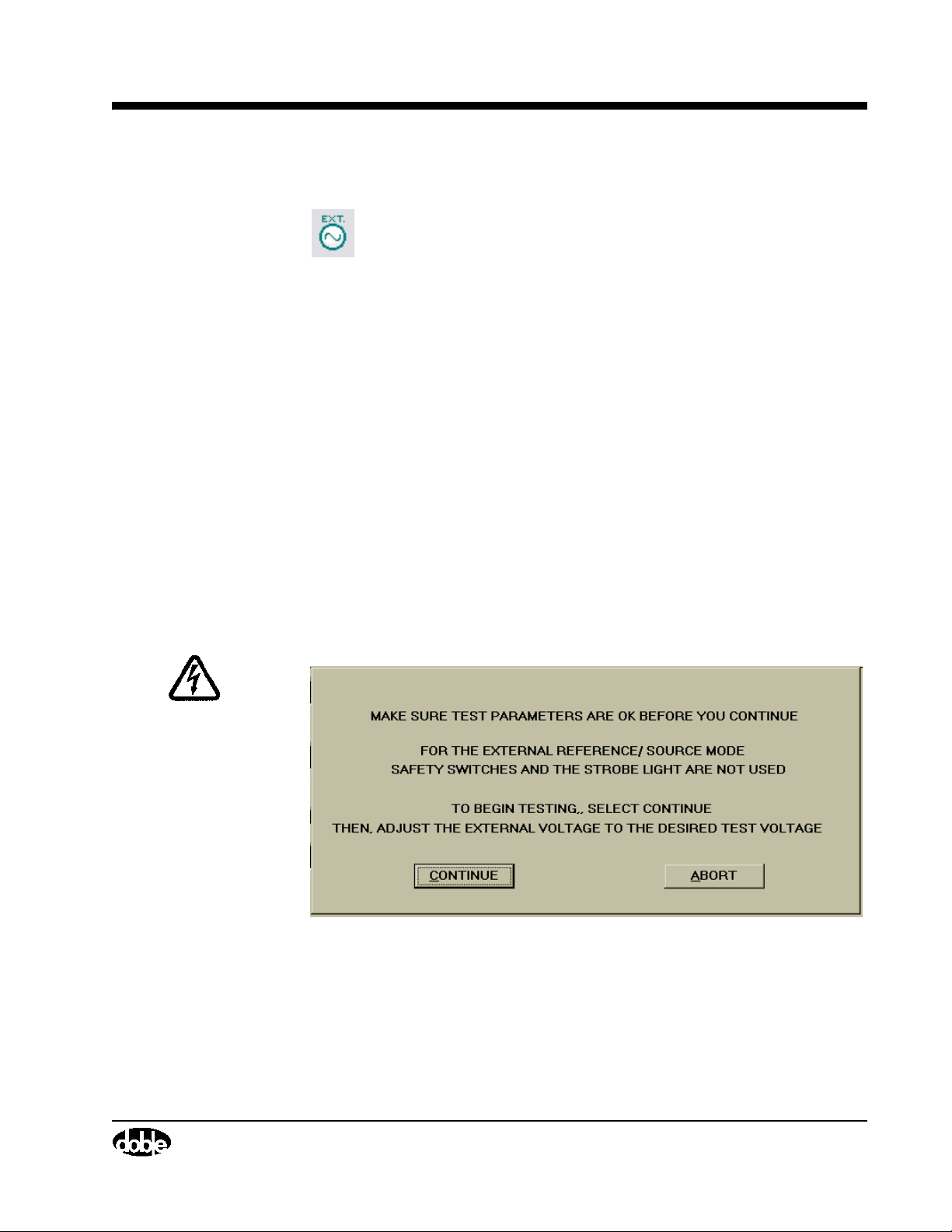
M4000 Insulation Analyzer User Guide
1. Select “External Reference” from “Mode” on the M4000 menu bar, or
click the External Source icon.
2. There are two test types: UST Measure Blue and GST Guard Blue. Select
UST Measure Blue from the Test Mode column.
3. There will be one clipboard sheet per test sequence with a maximum
number of tests in a sequence of 12.
4. Before running a test, enter the capacitance and power factor of the
reference capacitor, and the maximum test voltage.
5. Start a test by selecting Test from the menu bar, or by pressing F2, or by
clicking one of the lightning bolt icons (single or multiple tests can be
run). The line frequency will be measured and recorded.
6. You will be prompted to select a line number on which to place test
results, and whether the test is a Normal or Reversal (the first test for a
given line is by default a Normal test).
7. The safety screen is displayed with your selected settings. When you are
ready to begin the test, select the Continue button.
WARNING Observe the warning noted in Figure 3.10.
Figure 3.10 Warning
8. The M4000 is now ready to measure. The message “Set Test Voltage, Line
(x), Then Press F3 To Measure”, appears (where (x) is the selected line
number).
July 22, 2005
9. When you have set the external source to the desired voltage, press the F3
key. The message, “Do not change voltage - collecting data” appears.
72A-1230 Rev. F 3-13
Page 74

Running a GST-Guard Test
10. When the message, “Test Done, Line (x)”, where (x) is the selected line
number, press the F5 key to accept results. The mA, Watts, Percent Power
Factor, and Capacitance/Inductance is recorded on the clipboard sheet.
11. At this point, a reversal could be run for this line (x). To do this, repeat
steps 5 through 10, selecting the same line number, and selecting
“Reversal”. Since performing reversals requires reversing the leads on the
external source, it will be practical to perform a series of Normal tests first,
and then go back, reverse the leads to the external source, and perform a
series of Reversal tests corresponding to the Normal tests.
12. Once you have pressed F5 to save the reversal results, the line(s) that
contain both Normal and Reversal data will be check-marked in the CR
column. If you are testing indoors, it is unlikely you will need to perform
Reversal Tests.
Running a GST-Guard Test
1. Select “External Reference” from “Mode” on the M4000 menu bar, or
click the External Source icon.
July 22, 2005
2. There are two test types: UST Measure Blue and GST Guard Blue. Select
GST Guard Blue from the Test Mode column.
3. There will be one clipboard sheet per test sequence with a maximum
number of tests in a sequence of 12.
4. Before running a test, enter the capacitance and power factor of the
reference capacitor, and the maximum test voltage.
5. Start a test by selecting Test from the menu bar, or by pressing F2, or by
clicking one of the lightning bolt icons (single or multiple tests can be
run). The line frequency will be measured and recorded.
6. You will be prompted to select a line number on which to place test
results, either a Specimen Test or Setup Correction Test (the first test for a
given line is by default a Specimen Test), and either the Normal or
Reversal mode (the first test for each line is by default a Normal mode
test).
7. The safety screen is displayed with your selected settings. When you are
ready to begin the test, select the Continue button.
WARNING For the External Source Test Mode, safety switches and the strobe light
are not used. The External Source voltage is not controlled by the M4000.
Proper safety precautions must be taken.
3-14 72A-1230 Rev. F
Page 75

M4000 Insulation Analyzer User Guide
8. The M4000 is now ready to measure. The message “Set Test Voltage, Line
(x), Then Press F3 To Measure”, appears (where (x) is the selected line
number).
9. When you have set the external source to the desired voltage, press the F3
key. The message, “Do not change voltage - collecting data” appears.
10. When the message, “Test Done, Line (x)”, where (x) is the selected line
number, press the F5 key to accept results. The mA, Watts, Percent Power
Factor, and Capacitance/Inductance is recorded on the clipboard sheet.
11. At this point, if your test was a Specimen Test, you could run the Setup
Correction Test for this line (x). To do this, repeat steps 5 through 10,
selecting the same line number, and selecting Setup Correction Test. Since
performing the Setup Correction Test requires removing the high voltage
cable from the specimen, it will be practical to perform a series of
Specimen Tests first, and then go back, remove the high voltage cable
from the specimen, and perform a series of Setup Correction Tests
corresponding to the Specimen tests. If the losses of the High Voltage
cable and transformer can be guarded, it is not necessary to perform the
setup.
12. Once you have pressed F5 to save the Setup Correction Test results, the
line(s) that contain both the Specimen Test and Setup Correction Test will
be check-marked in the CR column.
13. You now have the option of repeating your tests in the reversal mode.
Simply repeat steps 5-12, always selecting the Reversal mode instead of
the Normal mode. When finished, you will have done either two tests per
line (no reversal tests made) or four tests per line (including reversal tests).
If testing indoors, Reversal Tests are not likely to be necessary.
July 22, 2005
72A-1230 Rev. F 3-15
Page 76
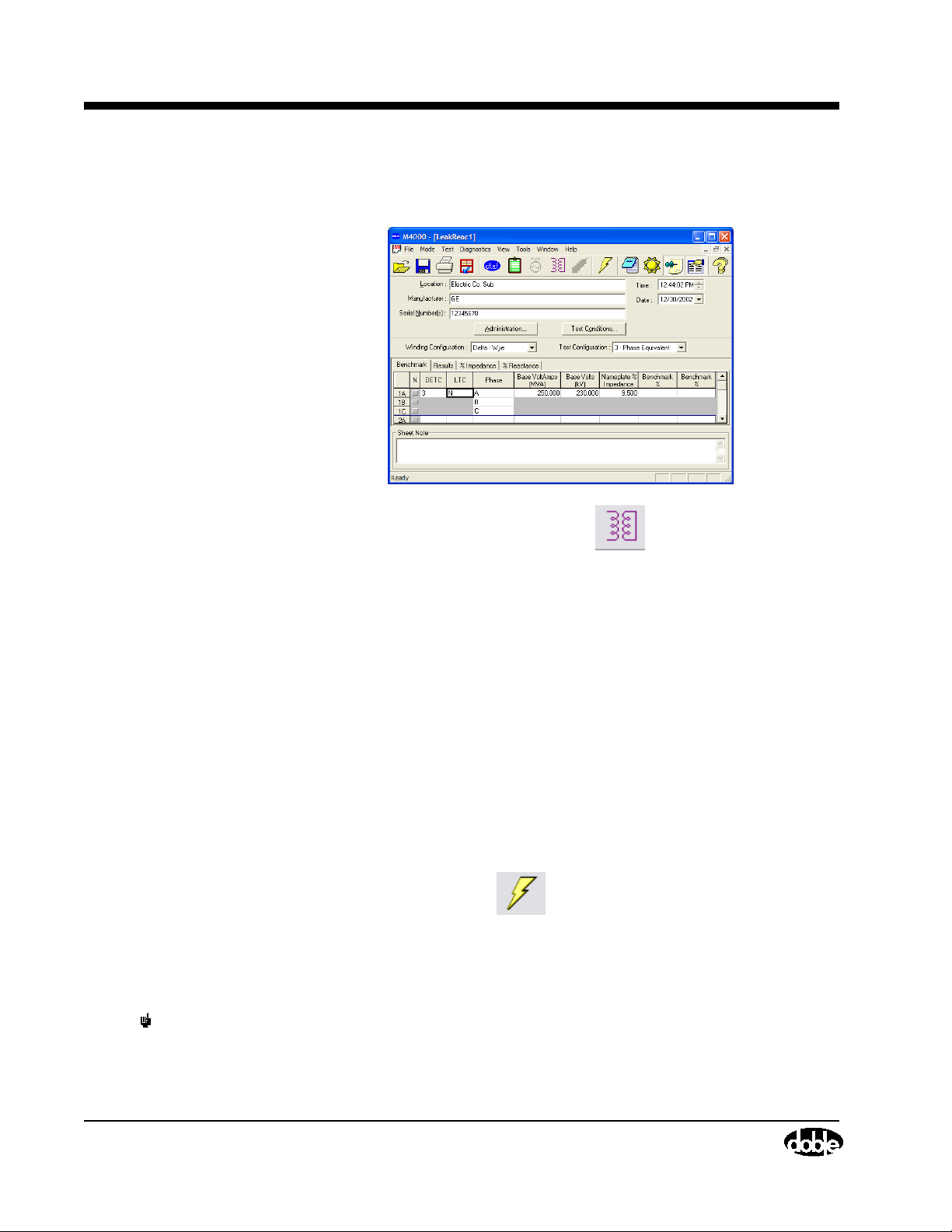
Running a GST-Guard Test
Leakage Reactance Test (Optional Software)
July 22, 2005
1. Click on the Leakage Reactance button to display the Leakage
Reactance test. Fill in Location, Manufacturer, and Serial Number.
2. Click the Benchmark tab and enter the nameplate data; this includes the
transformer impedance, and the MVA, kV, and tap positions at which it
was measured in the factory.
3. If this is not the first test, enter the benchmark values from the first test; if
it is the first test, enter the transformer nameplate impedance in both the
impedance and reactance benchmark fields.
4. Select the Winding Configuration, then the Tes t Configuration. If this is
the first test, perform a 3 phase equivalent test for comparison to
nameplate impedance, then three per phase tests (one per phase) to obtain
benchmark values for each phase for comparison to future tests.
5. Use the Phase column to identify the winding measured.
6. Click the Run a Test icon to start the test.
For complete details of this test, including test setup and connections, see
“Leakage Reactance Testing” in the Doble Test Procedures manual.
NOTE Always exit Windows before shutting off your M4000 Insulation
Analyzer.
3-16 72A-1230 Rev. F
Page 77
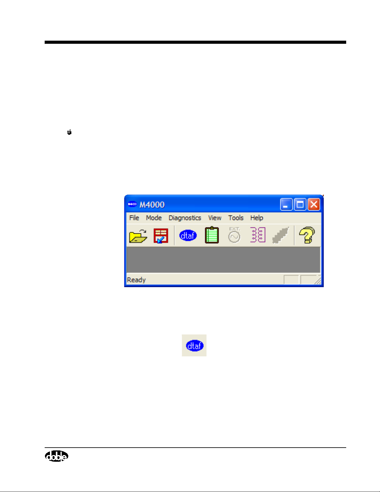
DTA Mode
NOTE The DTA Mode is not available unless the DTA software has been
DTA Tests
M4000 Insulation Analyzer User Guide
The remainder of this chapter describes how to run tests in the Doble Test
Assistant (DTA) Mode. For a complete description of the DTA program, refer
to the DTA Field System for Windows Users Guide. It is recommended that
this manual be available for reference.
purchased and has been loaded onto the M4000. If you are not using DTA,
all testing with the M4000 will be done in the “CIipboard” mode, as
described earlier.
With no test type selected, the main M4000 screen appears as follows:
Figure 3.11 M4000 Main Window
To test in the DTA Mode:
• Click on the icon,
or
• Select the “Mode” item on the menu bar using the mouse, or by
pressing ALT+M. Then select DTA option.
Either the icon or the menu method will bring you to the DTA Data Manager,
seen in Figure 3.12.
July 22, 2005
72A-1230 Rev. F 3-17
Page 78
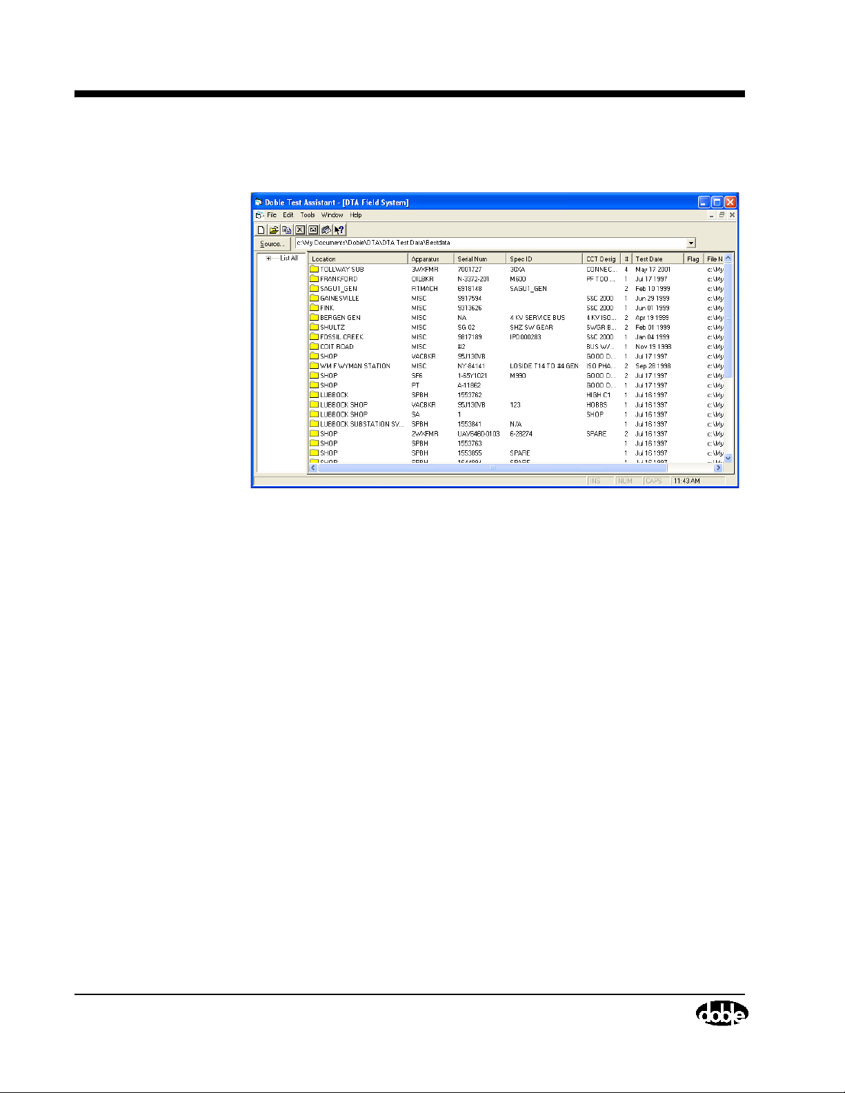
Running a GST-Guard Test
DTA Data Manager
July 22, 2005
Figure 3.12 DTA Data Manager
If you are using the windows version of
directory may appear as
DOS version of DTA, your working directory
to continue using the old directory, or wish to change the directory, proceed as
follows:
1. Click the Source button under the icons at the top of the screen.
2. From the pop-up window, select the new directory.
3. If using DTA version 4.1, run the program, and from the main screen:
4. Select Change from the Directory menu.
“C:\DOBLE\DTA\DATA”. If you have been using the
DTA for the first time, the working
is “C\DTA\DATA”. If you wish
3-18 72A-1230 Rev. F
Page 79
5. In the resulting pop-up Source Directory window, type in the desired
directory.
6. Click on “Dir List” if you want to browse through your computer files and
locate another.
Preparing for a DTA Test
NOTE The M4000 software version 3.xx requires DTA software version 5.xx.
1. Click the New icon if no previous tests for this apparatus are
available in DTA. This will create a new test and a new apparatus record.
2. If a previous test exists in your DTA directory, select it from the existing
apparatus tests in the right-hand column (if there is still no list, you may
have the wrong directory). Double click the desired apparatus in the righthand panel of DTA. To sort the displayed list, click on the column you
wish to sort by.
M4000 Insulation Analyzer User Guide
3. See the DTA Users Guide on how to arrive at the ID panel of the new test
4. If the open file contains previous test data, click the Next Test Date icon
5. Enter the atmospheric conditions by clicking the icon, or by
6. After entering necessary nameplate data and other apparatus identification,
7. Connect the test cables to the apparatus to be tested. See the DTA test form
Starting a DTA Test
1. Move the cursor to the “Test kV” field for the test to be performed. Type in
form, if necessary.
July 22, 2005
. This creates a new, blank, set of test sheets.
selecting Test Conditions from the View menu.
proceed to the Overall test form.
for help in making the connections for the tests listed, or see the Doble Test
Procedures manual.
the required test voltage.
72A-1230 Rev. F 3-19
Page 80

Running a GST-Guard Test
2. Start a test by clicking the icon, or by selecting from the Tes t
menu, Run Test - M4000. The “Test Conditions” window will appear if
you haven’t yet filled it in, with “Prb” in the air temperature field. This
indicates that air temperature will be entered automatically by the M4000
Temperature and Relative Humidity Sensor. If “Prb” doesn’t appear, then
the temperature/humidity sensor is not connected or is not working. An oil
temperature is required for oil-filled equipment. If the Temperature and
Relative Humidity Sensor is not used, an air temperature is also required.
3. Click the OK button in the Test Conditions window.
4. A “Run M4000 Test” pop-up window will appear.
5. Choose to run a single or a multiple test. A single test is a test for the line
the cursor is on. The multiple test will run all tests associated with one set
of connections. Select the appropriate choice (see the DTA manual for
details). You will most likely select Multiple Tests - Default.
July 22, 2005
6. In some types of apparatus, such as live-tank breakers or three-winding
transformers, both red and blue leads are generally used. In such cases,
DTA will ask you where each color lead was placed. You may select the
Setup button in any case, to check the selected test voltage for each test
you plan to do, as well as the default test circuit.
You will then be presented with a safety screen, where test circuit and voltage
can be checked. This is your last chance to be sure these parameters are
correct, and to abort the test if they are wrong.
3-20 72A-1230 Rev. F
Page 81
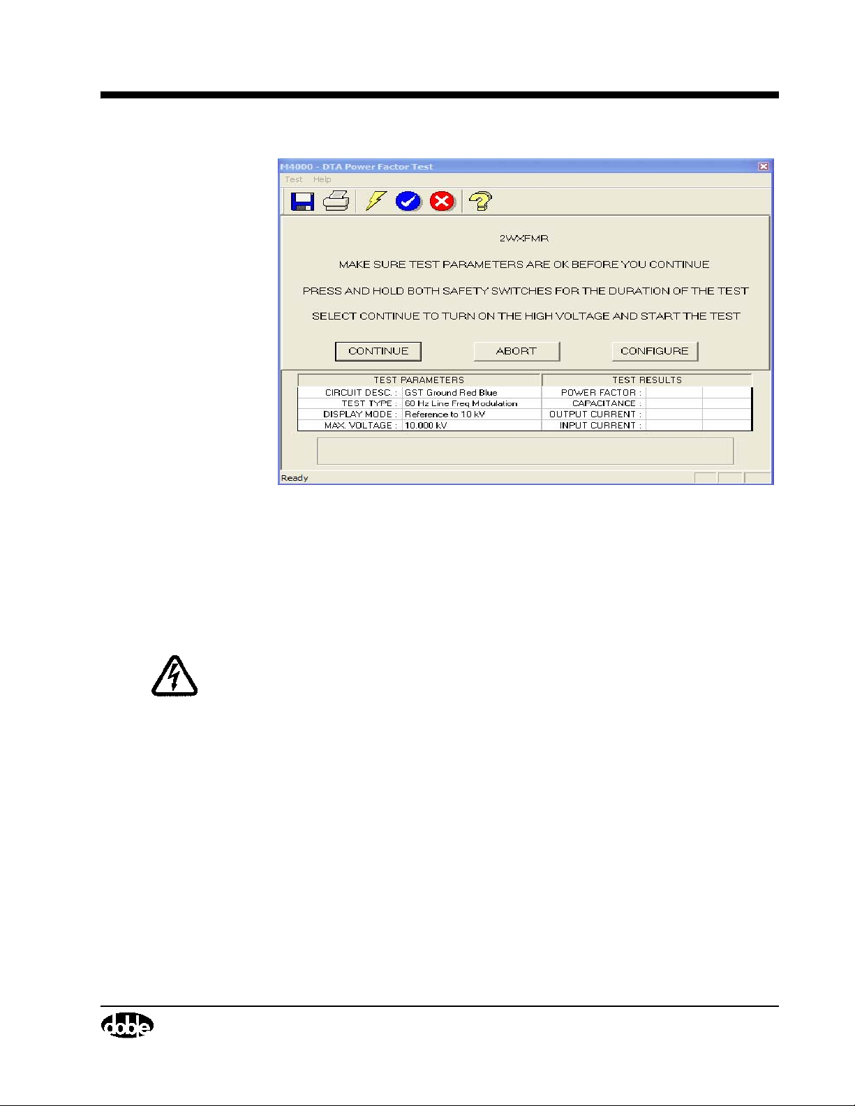
M4000 Insulation Analyzer User Guide
Figure 3.13 Safety Screen
1. Select the “Abort” button to return to DTA and make changes. Make this
choice if the test voltage needs to be changed.
2. Select the “Configure” button to change other test parameters, such as
Frequency or Test Type.
WARNING High voltage will be present after starting the test. Pressing the ESC or F4
key, or releasing a safety switch button, will turn off the high voltage.
When the parameters are correct, proceed with the test by:
3. Pressing both safety switch buttons.
4. Selecting the “Continue” button by highlighting it and pressing the
ENTER key.
July 22, 2005
72A-1230 Rev. F 3-21
Page 82
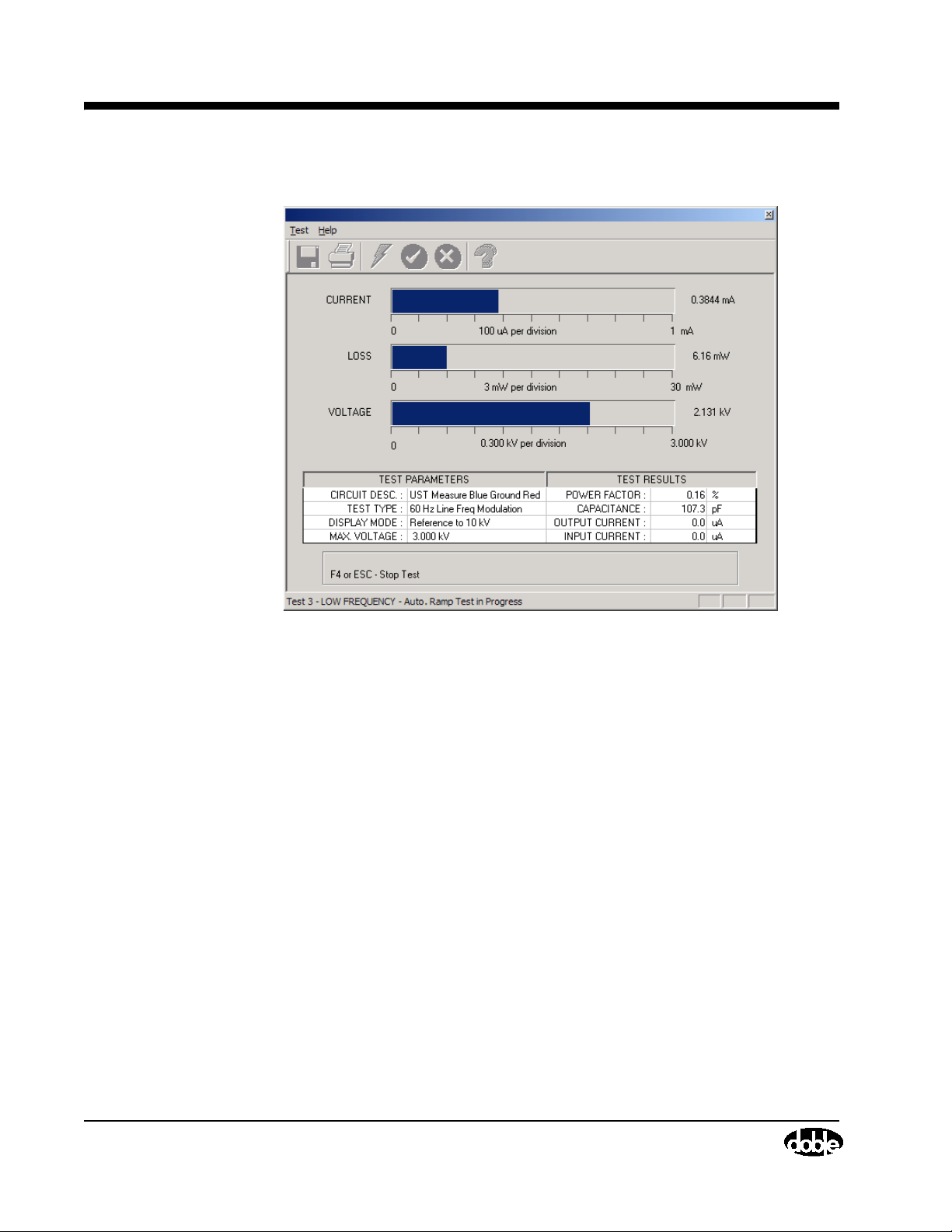
Running a GST-Guard Test
The following screen will appear:
July 22, 2005
Figure 3.14 DTA Test In Progress
The test will proceed automatically. The test specimen’s current, watts loss,
and voltage will be displayed in three analog meters (horizontal bars) on the
screen. The digital values for these parameters will be shown to the right of the
meters. The table on the screen describes test conditions and test results. The
horizontal bar at the bottom of the screen displays the status of the test.
For each test being performed, the voltage will ramp to the preselected
maximum twice. This is required to implement the selected interference
cancellation technique (Line Synchronized Reversal or Line Frequency
Modulation).
When the test is over, the status bar will read “Test Done”.
3-22 72A-1230 Rev. F
Page 83
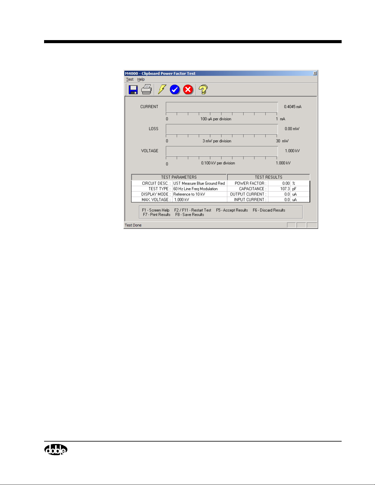
M4000 Insulation Analyzer User Guide
Figure 3.15 End of DTA Test
July 22, 2005
72A-1230 Rev. F 3-23
Page 84
Running a GST-Guard Test
DTA Icons and Function Keys
A list of function keys is displayed at the bottom of the screen after the test. In
addition, a row of icons appears at the top of the screen. An explanation of
each icon and key function follows:
July 22, 2005
Selecting this icon or
function key…
icon or F1 key Displays screen Help
icon or F2 or F11 key Restarts the test
icon or F5 key Accepts test results, returns to the
icon or F6 key Discards test results, returning to the
After pressing the F5 key to accept results, the test data and insulation rating
should be reviewed for correctness. The operator can continue to the next test
on the DTA form.
Does this…
DTA form, and copies the results into the
proper locations. When performing
multiple tests, only tests completed prior
to a stopped test will be accepted into
DTA
DTA form
NOTE Always exit Windows before shutting off your M4000 Insulation
Analyzer.
3-24 72A-1230 Rev. F
Page 85
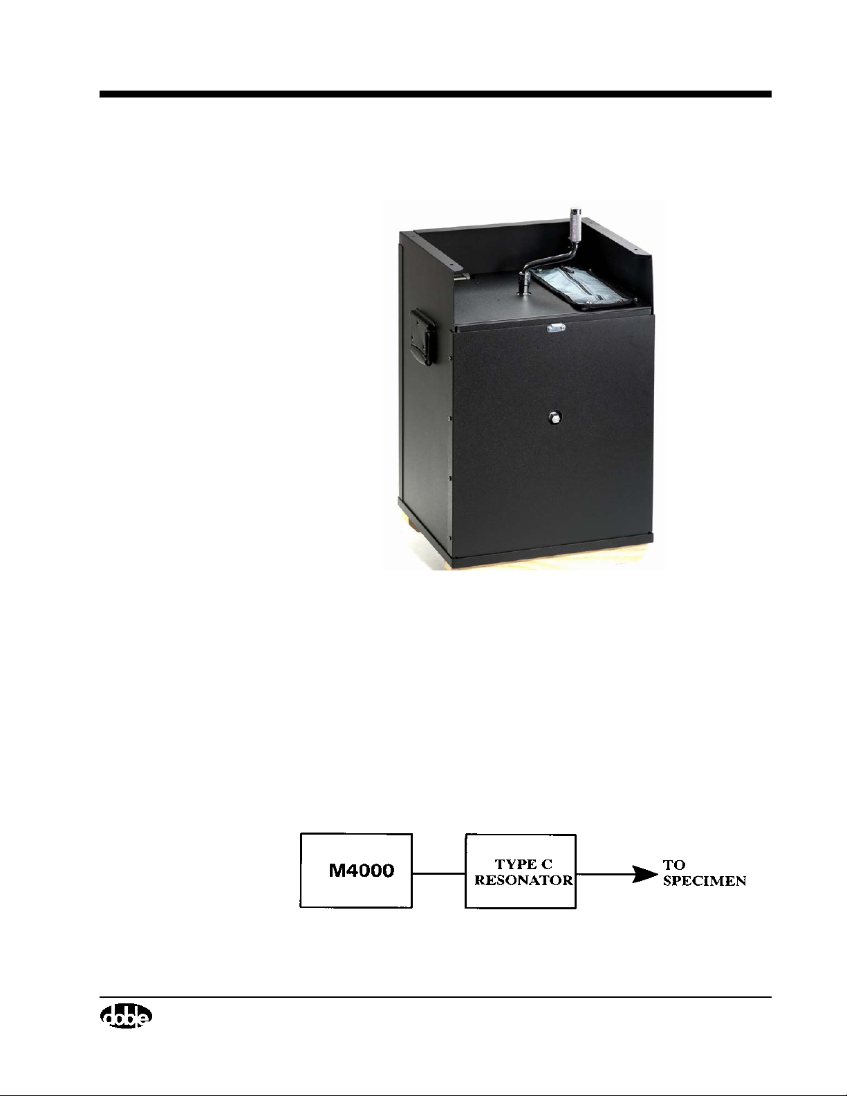
Using A Resonator
M4000 Insulation Analyzer User Guide
Figure 3.16 The Doble Resonator
The Doble Type C Resonating Inductor is an iron-core reactor with an
adjustable air gap, capable of resonating capacitances within a range of 0.05 to
1.0 microfarads at 60 Hz, and a range of 0.07-1.4 at 50 Hz. It is designed to
extend the current range of Doble 10 kV Power-Factor Test Sets up to four
Amps, assuming a lossless specimen, at voltages up to 10 kV. It extends the
use of the set for testing relatively long cable lengths, large rotating machines,
and other high-capacitance specimens. The ultimate range of the resonator
depends not only on the capacitance of the specimen but also the total losses of
the specimen under test.
Figure 3.17 Power-Factor Test Set and Type C Resonating Inductor
July 22, 2005
72A-1230 Rev. F 3-25
Page 86
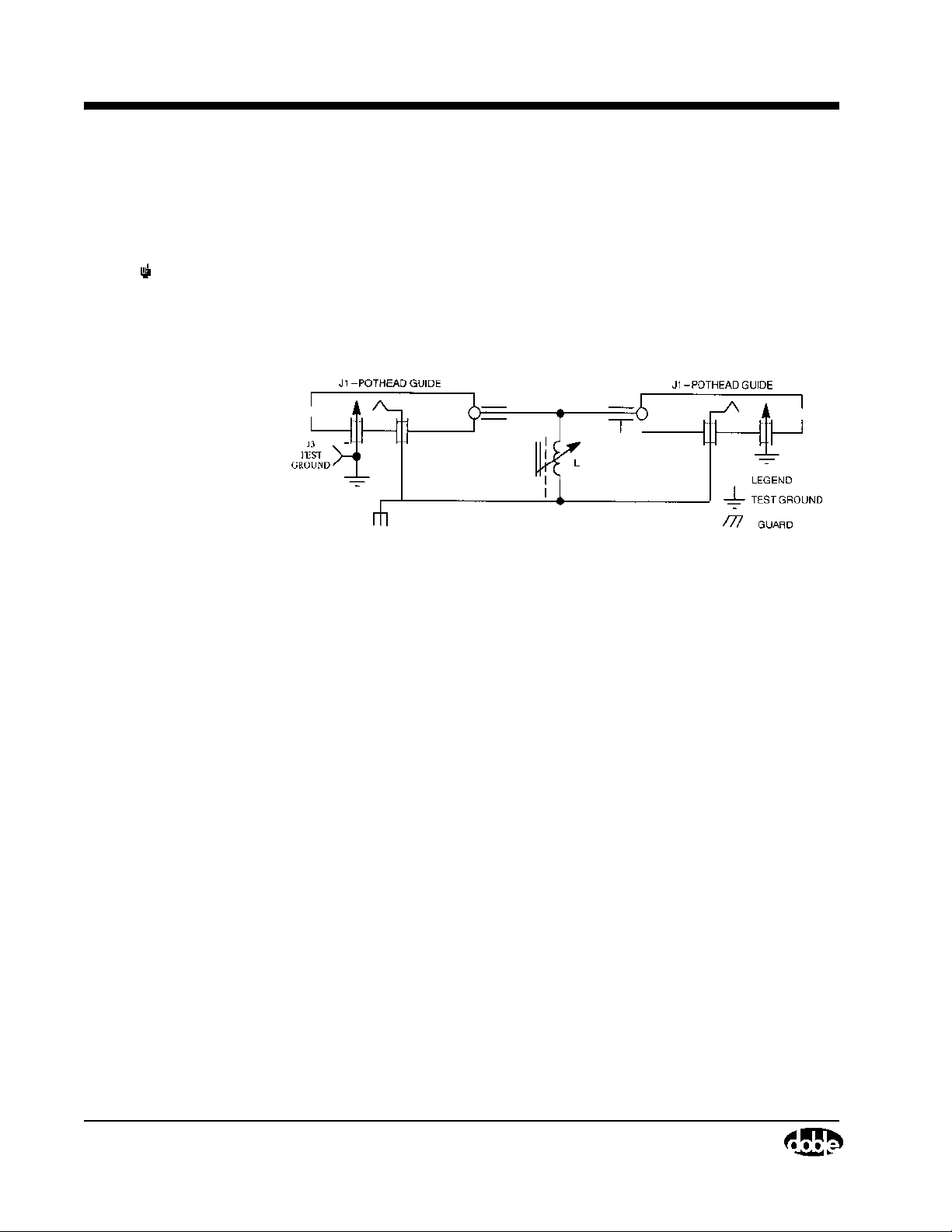
Operating Procedure of Type C Resonating Inductor
The Resonator, shown schematically in Figure 3.18, is contained in a metal
housing measuring 24 x 17 x 15 inches, and weighs approximately 185
pounds.
NOTE L adjustable from 7 to 140 Henries @60Hz.
Counter dial calibrated per calibration chart supplied with each unit.
Resonator chassis ground connected to test ground through cable shield
or external test ground lead.
Figure 3.18 Schematic of Type C Resonating Inductor
Operating Procedure of Type C Resonating Inductor
July 22, 2005
The Resonator is connected to the M4100 Instrument by means of an 8-ft,10
kV jumper cable. The regular 10 kV test cable is connected between the
Resonator and the test specimen. Cable receptacles will be found in the rear of
the Resonator case and can be used interchangeably (see Figure 3.18).
The Resonator is equipped with a core-clamping arrangement to reduce the
noise level when the Resonator is in use, and more importantly, to minimize
vibration. A speeder-type wrench is provided for use with this clamping
arrangement and for use in tuning the Resonator. The clamping adjustment is
located in the front vertical face of the Resonator while the tuning control is
located in the top panel. Turning the clamping adjustment approximately 180°
counterclockwise or clockwise will either unclamp or clamp the core,
respectively.
If the equivalent 10 kV charging current of the test specimen is known, the
Resonator may be set approximately by adjusting the tuning control until the
counter setting corresponds to this current. Mounted on the Resonator panel is
a reference chart relating the approximate counter reading to the specimen
current.
3-26 72A-1230 Rev. F
Page 87

M4000 Insulation Analyzer User Guide
Accurate tuning of the Resonator is obtained by turning the tuning control
until the current taken from the 120 volt supply is a minimum. To do this in
the Clipboard test mode
, follow this procedure:
1. Set the test for Line Sync Reversal (Under the LC column, select C).
2. Connect the M4000, the resonator, and the specimen as shown in
Figure 3.17
3. Select the “System” tab from the “Tools/Configuration” menu of the
M4000.
4. Set the M4000 to the “Manual Set Voltage” Ramp Mode.
NOTE Do not raise the test voltage beyond the allowed limit for the attached
specimen.
5. Unclamp the Resonator Core.
6. Raise the test voltage to about 2 kV, using the Page Up (fast) or Up Arrow
(slow) keys.
7. Observe the “input current” in the “Test Results” box.
8. Tune the Resonator until the “input current” of the M4000 is at a
minimum.
9. To fine tune, raise the voltage to the final test voltage, or as close to it as
possible, and repeat steps 7 and 8.
10. Reclamp the Resonator core.
11. Lower the voltage. The Resonator is tuned and you are ready to enter
information on the row in the clipboard you are using for the test.
12. When filling in the clipboard row prior to starting the test, remember to
select one of the “Line Sync Reversal” choices, C or F, in the LC (Line
Configuration) column. For a description of all the Line Configuration
choices, see “Glossary”, in the “Contents” selection of the M4000 “Help”
menu.
13. When finished using the Resonator, you may wish to return to Too ls /
Configuration and return the M4000 to its original settings of “Auto.
Ramp Voltage” Ramp Mode in the System Configuration.
Due to the high currents involved requiring the use of the Resonator, the 120
volt supply cord to the M4100 should be of relatively large wire gauge in order
to minimize the line voltage drop.
July 22, 2005
72A-1230 Rev. F 3-27
Page 88

Operating Procedure of Type C Resonating Inductor
General Description of Type C-1 Coupler - RIV Test Procedure
NOTE Recommended for M2H only.
RIV (Radio-Influence Voltage) measurements may be of value in detecting
corona on all types of insulation systems. One of the most common
applications of RIV is with reference to rotating machinery insulation. The
RIV Coupler in Figure 3.19 permits coupling of the radio-noise meter to the
specimen with AC test voltage provided by the test set (refer to ANSI Guide
C68.3- and IEEE Standard 454, “IEEE Recommended Practice for the
Detection and Measurement of Partial Discharges (Corona) During Dielectric
Tests”). The method usually employed detects partial discharges in the 1 MHz
range. While some radio-noise meters use a diode-noise generator to produce
reference signals, it is also feasible to use a radio receiver in conjunction with
a standard signal generator. The signal generator should be capable of putting
out a signal in the vicinity of 1 MHz, 50% modulated at 400 Hz, with a
metered, adjustable output between 1 and 100,000 microvolts.
July 22, 2005
Figure 3.19 is a schematic of the Test Set complete with Resonator and
coupling network (i.e., RIV Coupler) arranged for RIV (Radio-Influence
Voltage) measurements. Note that the three components are arranged
physically in series by means of two shielded jumper cables furnished with
this equipment. One of the cables is connected between the M4100 Instrument
and the Resonator. The second is connected between the Resonator and the
RIV Coupler terminal marked “TRANSFORMER”. A standard 60-ft cable is
used between the specimen and the RIV Coupler terminal marked
“SPECIMEN.”
For low-capacitance specimens, when the Resonator is not used, connection is
made directly from the M4100 Instrument to the RIV Coupler terminal
marked “TRANSFORMER.”
Connection between the RIV Coupler and the radio-noise meter used for
making RIV measurements is made by means of a single-circuit lead and
telephone plug which plugs into the receptacle marked “DETECTOR” in the
front of the Coupler. A separate common ground must be run from the M2H
transformer case to the ground terminal of the radio-noise meter. To minimize
shunting effects on the radio-noise meter, the capacitance between the RIV
measuring lead and ground must be kept low. For this reason, use of a
common two-conductor or shielded single-conductor lead is not recommended
between the RIV Coupler and radio-noise meter.
3-28 72A-1230 Rev. F
Page 89
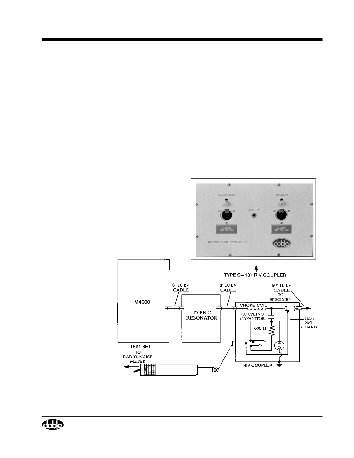
M4000 Insulation Analyzer User Guide
Note that the circuit in Figure 3.19 is so arranged that, when the telephone
plug is removed from the Coupler, the lower terminal of the coupling capacitor
is connected to the test-setguard circuit. In this way, the Coupler may be left
connected for power-factor tests. The telephone plug must be removed or the
capacitor current and losses will be included in the measurement. Note that if
the telephone plug (i.e., the radio-noise meter) is left connected, the Coupler
adds only a small watts loss to the measurement being made. Despite the
shielding, some stray capacitive currents are measured. The stray currents (at
10 kV) may be measured with the Coupler connected for test but with no
specimen connected. For low-capacitance specimens, this current may be
subtracted before the power-factor calculation is made, if it is appreciable
compared with the specimen current.
The RIV Coupler is contained
in a metal housing measuring
9¼ x 14½ x 11½ inches, and
weighs approximately 25
pounds.
Figure 3.19 Coupling Arrangement for RIV Measurements with 10 kV Test
Sets
July 22, 2005
72A-1230 Rev. F 3-29
Page 90

Operating Procedure of Type C Resonating Inductor
NOTE When the telephone plug is not connected to the Coupling Box, the lower
terminal of the Coupling Capacitor is connected to the Test Set Guard
Circuit. When the telephone plug is inserted into the receptacle, the
Guard connection to the lower terminal of the Coupling Capacitor is
removed and ground is applied to the low end of the 600 Ohm resistor via
the barrel of the telephone plug.
July 22, 2005
3-30 72A-1230 Rev. F
Page 91

4. M4100 Instrument Troubleshooting
Assigning A Trouble To The M4100 Instrument (Or The M4200c Controller)
This section is intended to guide the operator’s initial steps in troubleshooting
problems with the performance of the M4000 Insulation Analyzer. It outlines
the resources available for diagnosis of problems and points to specific
information in this chapter, or to the M4200c Controller manual. The overall
purpose of this chapter is to support user personnel in diagnosing and fixing a
majority of the difficulties that might be encountered in the field.
NOTE If it is clear that a problem is associated with the M4200c Controller, refer
to the M4200c Controller manual. If it is clear that a problem is associated
with the M4100 Instrument, continue through this chapter. If there is
doubt as to the cause of a problem, proceed to the next page.
Doble’s Customer Service staff is always available to support its
customers if more guidance is required.
Quick Checks
Certain problems are very common and attributable to operator error or
mishandling. Before investigating more complex causes of observed
problems, run through the following list to determine if a simple oversight is
the cause of trouble:
July 22, 2005
72A-1230 Rev. F 4-1
Page 92
Troubleshooting Resources
Table 4.1 Quick Checks: Can You Answer Yes To These Items:
Item
The communications cable is securely connected between the
M4200c (or third-party controller) and the M4100.
Both the M4200c and M4100 are turned on and connected to an
active, stable power source, appropriately rated and grounded.
Both safety switches were held closed during a specimen test and
released between tests as required.
The test cables are securely connected to the specimen under test,
and the specimen is ungrounded.
All the test leads are in good condition.
The printer is correctly loaded with paper of the proper kind.
July 22, 2005
NOTE A majority of test set problems involve only the test leads, i.e. the High
Voltage Test Cable and the Low Voltage Test Leads. Be especially alert to
the condition of these items. They can be readily tested by following the
procedures in ”Running Other Tests” on page 4-42.
Troubleshooting Resources
The operator should consult this chapter first when a problem appears. It will
help isolate the problem to the M4200c or the M4100 and will point to the
most appropriate resources available to resolve the problem as quickly as
possible. There are four categories of resources available, and these are
summarized in Table 4.2.
Neither unit has been dropped recently or otherwise undergone
rough treatment.
The floppy disk drive was empty during M4000 software boot-up.
The Num Lock and Caps Lock keys on the keyboard are switched
off.
4-2 72A-1230 Rev. F
Page 93

M4000 Insulation Analyzer User Guide
Table 4.2 M4000 Troubleshooting Resources
Resource Description M4100
Reference
Symptoms The most basic troubleshooting tool is the
observation of a symptom of trouble by the M4000
operator. It is often the starting point for more
detailed diagnostics.
Error Messages The M4000 Insulation Analyzer automatically
recognizes certain exception conditions and
displays corresponding error messages to the
operator. A Help button is also available in each
displayed message box to provide guidance on
suggested causes and cures.
Diagnostics The M4000 supports automated self-diagnostic tests
that are useful in validating system operation and
troubleshooting problems that may occur.
Diagnostics should be run on a regular basis to
ensure that the M4000 Insulation Analyzer is
functioning properly. The Diagnostics should also
be used to investigate potential causes of error
messages. Test results should be sent to Doble if
Doble assistance is being requested.
Other Tests Certain relatively simple external and internal tests
can be performed to characterize a problem and
point to a specific solution. In some cases these tests
can avoid the need for component swapping as a
diagnostic tool.
page 4-12
page 4-16
page 4-21
page 4-42
and
page 4-50
July 22, 2005
Isolating Trouble
72A-1230 Rev. F 4-3
The first step in pinpointing a problem is to determine whether the problem
lies with the M4200c (or third-party controller) or the M4100. Consult
Table 4.3 to determine which is the malfunctioning unit and what to do next.
Page 94

Avoiding Problems
Table 4.3 Isolating the Problem
Observation Suggested Action
July 22, 2005
A numbered error message
appears in the display.
An un-numbered error
message appears in the
display.
The M4000 fails to
complete the test of a
specimen or yields unusual
results.
The M4000 does not print as
expected.
A Diagnostics test has
failed.
Either the display or
keyboard is nonresponsive
or responds in an
unexpected manner.
The M4100 is likely to be at fault. See
”Troubleshooting from Error Messages”
on page 4-16. Also, click on Help for
further guidance.
The M4200c is likely to be at fault. See
”Troubleshooting from Diagnostics”
on page 4-21. Also, click on Help for
further guidance.
The M4100 is likely to be at fault. See
”Troubleshooting from Symptoms”
on page 4-12.
The problem lies with the M4200c. See the
M4200c Controller manual.
If the Communications Loopback Test has
failed, the fault lies with the M4200c; see
”Communications Loopback Test”
on page 4-40. If any other Diagnostics test
has failed, the M4100 is probably at fault;
see ”Running Other Tests” on page 4-42.
The M4200c is at fault. See the M4200c
Controller manual.
The M4000 software is
either not working or acting
erratically.
Any other symptom, not
described above, is evident.
The fault probably lies with the M4200c.
See the M4200c Controller manual.
See ”Troubleshooting from Symptoms”
on page 4-12.
Avoiding Problems
The M4000 test set is rugged and can give many years of trouble-free service
if it is handled with reasonable care. The following practices are suggested to
minimize performance problems in the field.
Precautions It is recommended that the following precautions be followed:
• Keep the M4100 Instrument and Accessories clean and dry. Select a
suitable storage location.
4-4 72A-1230 Rev. F
Page 95

M4000 Insulation Analyzer User Guide
• Do not drop the instrument.
• Do not bend or coil the High Voltage Test Cable too tightly, no smaller
than a 12-inch diameter coil.
• Do not use test leads for hoisting.
• Do not drag the High Voltage Test Cable or other leads across the
ground, particularly if the ground surface is crushed stone.
• Do not yank at a Low Voltage Test Lead to disconnect its outboard
clip, and do not yank any lead from its instrument connection.
Preventive Maintenance
The following preventive maintenance actions are suggested:
• Periodically check all screw connections for tightness.
• Examine the High Voltage Test Cable periodically and check for
corrosion, loose screws, gouges or cuts in the outer protective jacket,
and for signs of tracking on the inboard and outboard potheads.
• Examine the inboard connectors of the various leads and accessories
periodically.
• Periodically examine the connectors on the instrument case.
• Visually examine the safety switches periodically for worn
connections.
• Periodically check that the HV Pothead receptacle on the instrument
case is clean and dry.
• Periodically run the Calibration Verification Test (page 4-26) to check
for proper system operation.
Detailed Troubleshooting Of The M4100 Instrument
This section provides information that is useful in:
• Troubleshooting problems related to M4100 performance
• Performing specific external and internal checks to isolate the cause of
M4100 malfunctions
• Accessing and replacing M4100 components which have failed
• Installing upgrades to certain M4100 components
July 22, 2005
NOTE To address M4000 test set performance problems, it is important to follow
the guidelines in the previous section before making the assumption that
the M4100 is at fault.
The major parts of this section and their purposes are summarized below:
72A-1230 Rev. F 4-5
Page 96

Avoiding Problems
Section Purpose Page
Reference
July 22, 2005
Overview of M4100 Get introduced to the M4100
Instrument
Overview of
Individual
Identify all customer-replaceable
components of the M4100
Replaceable
Components
Troubleshooting from
Symptoms
Obtain detailed guidance on
troubleshooting, starting with
observed symptoms of
malfunction
Troubleshooting from
Error Messages
Obtain detailed guidance on
troubleshooting, starting with
observed error messages
Troubleshooting from
Diagnostics
Get help in running and
interpreting the results of
automated self-diagnostic tests
Running Other Tests Identifying additional tests that
can be run to troubleshoot
problems without gaining access
to internal components
page 4-7
page 4-9
page 4-12
page 4-16
page 4-21
page 4-42
Accessing M4100
Components
Learn how to remove the
instrument’s covers and identify its
page 4-46
major components
M4100 Internal
Checks
Learn about internal checks that
can be performed to diagnose
page 4-50
problems without replacing
components
Replacing M4100
Components
Obtain detailed instructions on
replacing components for the
page 4-56
purpose of diagnosis or repair
Replace:
Front Panel Assembly page 4-58
Guard Front Panel Board page 4-61
4-6 72A-1230 Rev. F
Page 97

M4000 Insulation Analyzer User Guide
Section Purpose Page
Reference
Amplifier Assembly page 4-63
Guard Mode Switch Board page 4-66
Timing Board page 4-68
DSP/CPU Board page 4-70
Safety Board page 4-72
Main Reference Assembly page 4-74
Guard Board page 4-76
Low Voltage Power Supply Board page 4-78
Overview of M4100
The M4100 stimulates the insulation specimen under test with an AC voltage
up to 12 kV in magnitude, an applied potential whose fundamental frequency
is at or near the power system frequency. The instrument directly measures the
specimen’s current and voltage to derive all reported output parameters
relating to insulation properties, including power loss, capacitance and power
factor. The applied AC voltage is asynchronous with the power line frequency
so that electrostatic interference can be filtered out. The M4100 contains
digital control, power, analog measurement and safety circuits.
Heater/Temperature Controller
Board
Field Calibration Reference page 4-82
I/O Protection Board page 4-83
Transformer page 4-85
HV Pothead page 4-91
Fan Filter page 4-93
Fan page 4-94
page 4-80
July 22, 2005
An overview of the M4100 and its major components gives a good starting
point for gaining basic functional knowledge that is helpful in effective
troubleshooting. A block diagram of the M4100, illustrating its major
components, appears in Figure 4.1 on page 4-8.
72A-1230 Rev. F 4-7
Page 98
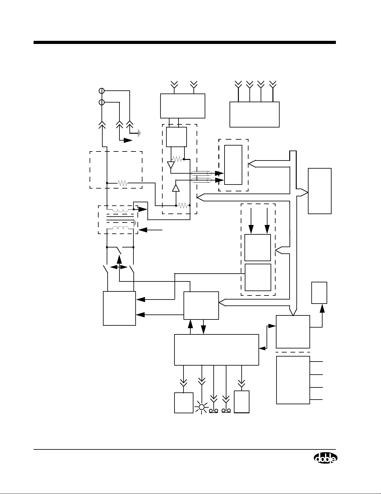
Avoiding Problems
HV Pothead
LV
Red
LV
Blue
Red
Guard
Front
Panel
Mode
Board
(04D-0536)
Switch
Test Cable
High Voltage
1000V
Field
Calibration
100V
Reference
Blue
(03D-1051)
July 22, 2005
(04D-0551)
Guard Mode Switch Board
Reference
Assembly
(03D-1052)
Main Reference
200V 12kV
Safety Relays
Resistor
Transformer
Assembly
Amplifier
(03D-1055-01)
Safety
Guard Board
Board
(04D-0544)
(04D-0527
18-Bit
A/D Converter
Board
DSP/CPU
(04D-0520)
Crystal
Line Sync
Backplane Bus
Fan
Timing Board (04D-0533)
Time
Base
Generator
Sine
Wav e
Generator
Heater/
Controller
Temperature
I/O
Board
Protection
(04D-0546)
RS/232
Board
Low Voltage
Power Supply
Tem p/
Humidity
Strobe
Sensor
Safety Switches
M4200c
Controller
Figure 4.1 M4100 Block Diagram
4-8 72A-1230 Rev. F
Board
(384-0138)
–15V
+15V
–5V
+5V
Page 99

Overview of Individual Replaceable Components
An overview of each of the instrument’s replaceable components is provided
below. While a few other M4100 components exist, they are not
field-replaceable.
M4000 Insulation Analyzer User Guide
Front Panel Assembly
03D-1056
Guard Front Panel Board
04D-0536
Amplifier Assembly
03D-1055-01
Guard Mode Switch Board
04D-0551
Timing Board
04D-0533
The Front Panel Assembly includes all front
panel-mounted components, including the
Guard Front Panel Board and the I/O
Protection Board.
The Guard Front Panel Board provides
interconnections for the low voltage test
leads and the Guard Mode Switch Board.
The Amplifier Assembly converts the AC
input signal – whether synchronous with the
power system frequency or derived from a
crystal oscillator – to AC test stimulus
power. It drives a 10 kV step-up transformer
through safety relay contacts.
The Guard Mode Switch Board consists of
an array of semiconductor (FET) switches
that routes the measured specimen and
reference currents to the Guard Board, in
accordance with the desired test mode.
The Timing Board serves two main
purposes. First, it provides a high speed
clock for A/D conversion. The clock is
either synchronized to a selected test
frequency, generally between 40 and 70 Hz,
or synchronized to the line frequency.
Second, this board provides a frequency
counter used to measure the test frequency.
July 22, 2005
DSP/CPU Board
04D-0520
72A-1230 Rev. F 4-9
The DSP/CPU Board serves as the M4100
system controller and as a digital signal
processor for high speed algorithmic
processing of analog signals.
Page 100

Avoiding Problems
July 22, 2005
Safety Board
04D-0544
Main Reference Assembly
04D-0583
Guard Board
04D-0527
Low Voltage Power Supply
Board
384-0138
The Safety Board latches off the Amplifier
Assembly and opens the safety relays when
a potential operator safety hazard or
hardware overload is detected. It also
reports safety status and receives safety
commands from the DSP/CPU Board.
The Main Reference Assembly stores
calibration standard values used in
comparing the measured specimen power
factor and capacitance values.
The Guard Board provides signal
conditioning of the specimen and reference
currents for A/D conversion. Its functions
include shunt selection, signal scaling,
anti-alias filtering and A/D conversion. The
optimum current range is selected
automatically unless the operator manually
specifies a range.
The Low Voltage Power Supply Board
supplies +5 VDC, –5 VDC, +15 VDC and
–15 VDC for internal use throughout the
M4100 Instrument.
Heater/Temperature
Controller Board
04D-0547
Field Calibration Reference
(Optional)
04D-0524
The Heater/Temperature Controller Board
senses the internal temperature and controls
the fan.
The Field Calibration Reference provides a
means for checking calibration of the
M4100 in the field using pre-calibrated,
precision resistors. It can also be used as an
external reference for other types of
measurements, such as transformer
short-circuit impedance tests and turns-ratio
tests.
4-10 72A-1230 Rev. F
 Loading...