

Page 1

19770 Bahama St.
Northridge, CA. 91324
V: 818.898.338 0
F: 818.898.3360
[email protected]
www.dnfcontrols.com
ST600-KIPRO
User Manual
ST600-KIPRO User Manual Page 1 of 14
Page 2
TABLE OF CONTENTS
1.00
01/24/17
Original draft.
GETTING STARTED ............................................................................................... 3
EQUIPMENT LIST ................................................................................................. 3
INSTALLATION..................................................................................................... 4
SYSTEM CONFIGURATION WEB PAGE .................................................................. 5
CONNECTION TO AJA KI-PRO .................................................................................. 6
OPERATION ........................................................................................................ 7
CLIP LIST WEB PAGE ............................................................................................ 8
FUNCTION TABLE .................................................................................................9
8.
KEY LAYOUT ....................................................................................................... 11
9.
SPECIFICATIONS ................................................................................................. 12
10.
DNF CONTROLS LIMITED WARRANTY .................................................................. 14
11
REVISIONS
ST600-KIPRO User Manual Page 2 of 14
Page 3

1. GETTING STARTED
Qty
Component
DNF Part Number
1. Go to Installation Section to set up ST600.
2. Go to System Configuration Section to set static IP address, Subnet Mask, and
Gateway address.
3. Go to Remote Device Assignment Section to enter IP addresses for remote devices that
ST600 will communicate with.
4. Go to System Configuration section to set default settings.
2. EQUIPMENT LIST
1 ST600 Panel ST600-KIPRO
1 USP3 POWER SUPPLY included
1 POWER CORD included
ST600-KIPRO User Manual Page 3 of 14
Page 4
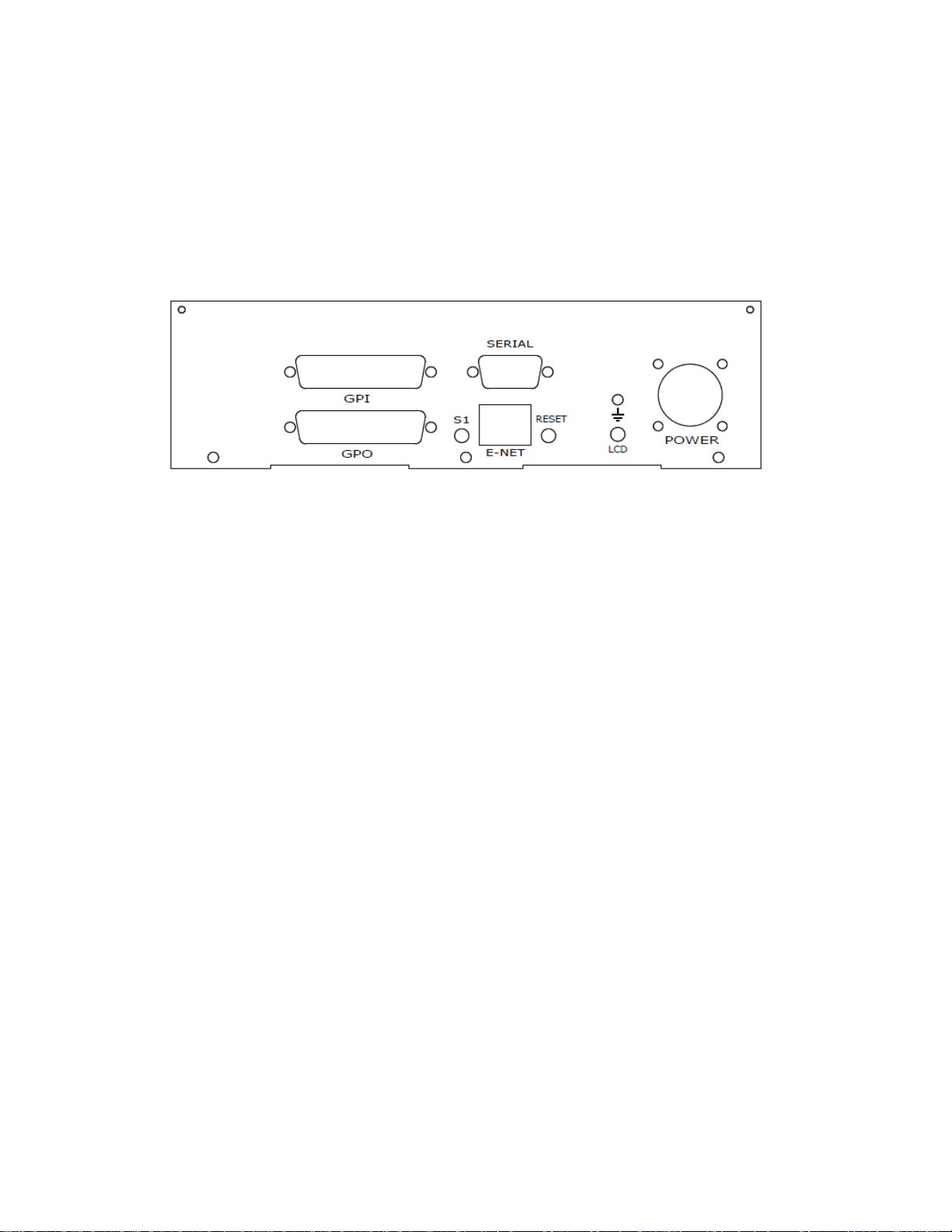
3. INSTALLATION
IP Address:
192.168.10.217
Subnet Mask:
255.255.255.0
Gateway:
192.168.10.1
1. Connect supplied power supply to POWER connector
2. Connect Ethernet cable to ETHERNET connector.
Rear View
The ST600 is configured using a standard web browser (Internet Explorer, Firefox, and Chrome). Enter
the IP address in the Address/ URL bar, typically located at the top of the web browser page, to access
the Home Page. Use the links on the left side of the Home Page to access the desired configuration web
pages.
All configuration settings are saved in non-volatile memory in the ST600. Settings are retained when
power is removed.
Settings may be uploaded to a computer as a configuration file (.dnf) for storage. Configuration files may
be downloaded from a computer into the ST600 to restore a saved configuration. A configuration file
contains all of the ST600’s configurations except IP address, subnet mask, and gateway address. The
ST600 does not support partial configuration upload or download. The configuration file is a not a text
formatted file. It cannot be viewed or modified with a text editor.
DEFAULT ETHERNET CONFIGURATION
To access the System Configuration web page, use the following log-on when prompted:
Username: dnfuser
ST600-KIPRO User Manual Page 4 of 14
Password: controls
Page 5
4. SYSTEM CONFIGURATION WEB PAGE
ST600
will automatically reboot.
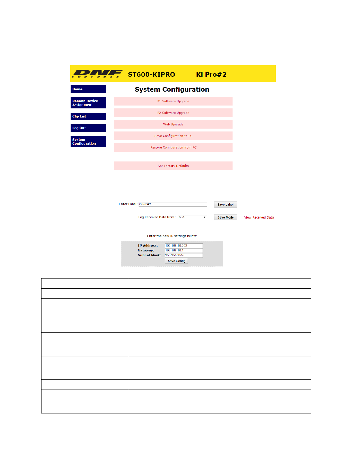
P1 Software Upgrade: Use this link to install the P1 upgrade file provided by DNF Controls
P2 Software Upgrade: Use this link to install the P2 upgrade file provided by DNF Controls
Web Upgrade: Use this link to install the Web pages upgrade file provided by DNF Controls
Save Configuration to PC: Use this link to save the ST600 current configuration to a configuration file
a computer. The web browser will prompt for file name and directory.
on
The file
extension must be ‘dnf’.
Restore Configuration from PC: Use this link to download a configuration file from your computer to the
The web browser will prompt for directory and configuration file
extension must be ‘dnf’.
will NOT change the IP address, subnet mask or gateway address. The
Set Factory Defaults:
ST600.
name. The file
Use this link to reset all ST600 configuration settings to factory defaults.
This
Enter Label Enter label to be displayed on top right of all web pages
Enter the new IP settings below: Enter the new IP address, Gateway, and Subnet Mask. Click on “Save Config”
to
save the new entries. The ST600 will automatically reboot.
ST600-KIPRO User Manual Page 5 of 14
Page 6
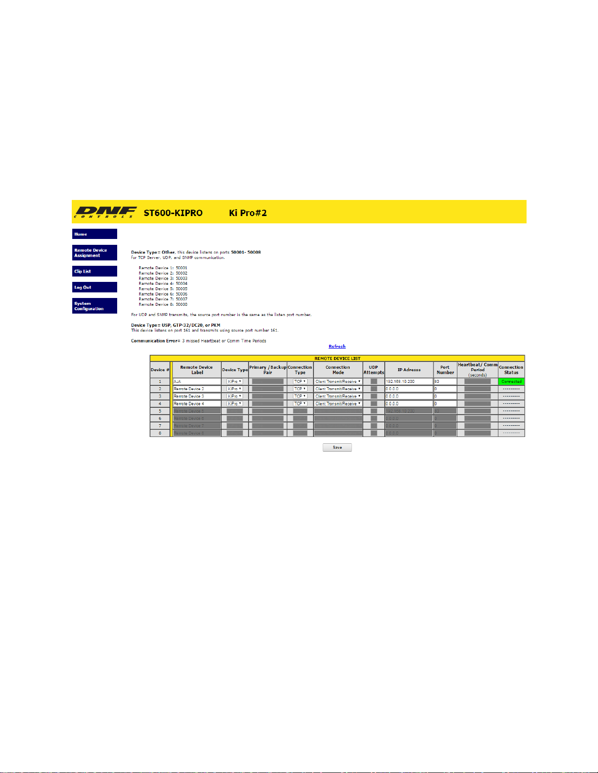
5. CONNECTION TO KI PRO
1. Go to Remote Device Assignment page to add the Ki Pro IP Address.
2. Enter the IP address of the Ki Pro and set the Port number to “80”.
3. Press “Save” to save your changes.
ST600-KIPRO User Manual Page 6 of 14
Page 7

6. OPERATION
1. LCD DISPLAY
During normal operation, the top row of the display shows the selected time mode and
current time location of the selected Ki Pro.
For example: 01:12:09:23
Second Row shows name of loaded clip..
For example: Clip: SC1TK47
2. TRANSPORT CONTROL
Select the desired transport function by pressing the appropriate key
The Real-Time Status Indicators will light to indicate the DDR's current transport mode.
For example: Pressing [PLAY] will put the DDR into the PLAY mode.
3. LOAD CLIP or CREATE CLIP FOR RECORD FROM WEB PAGE
• Easily Load a Clip on to the Ki Pro from the “clip list” web page
• Create a New Clip for Record
The PLAY Status Indicator will turn on when the DDR is in PLAY mode.
4.
CUE POINTS
• Press [MARK] to mark the Ki Pro’s current time into the selected Cue Point #.
• Use [↑] or [↓] to step through marked cue points
ST600-KIPRO User Manual Page 7 of 14
Page 8
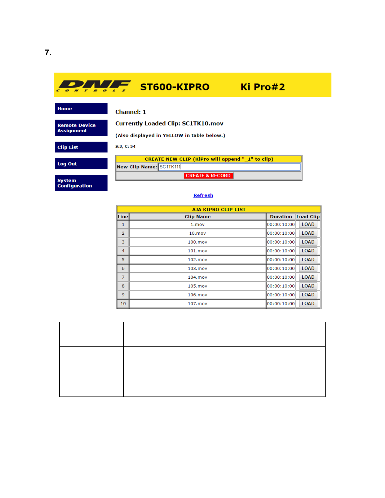
CLIP LIST WEB PAGE
Load Clip For Play
Create Clip for
Record
Choose from the list of Clips and simply press “LOAD”.
Clip will load and show time and name of loaded clip on ST600 LCD display.
Type in name you wish to create for your clip and click on “Create & Record”
on ST600 Clip List web page to create the desired clip.
*Record will start once “Create & Record” is pressed on web page
or when
Record key is pressed on the ST600
ST600-KIPRO User Manual Page 8 of 14
Page 9
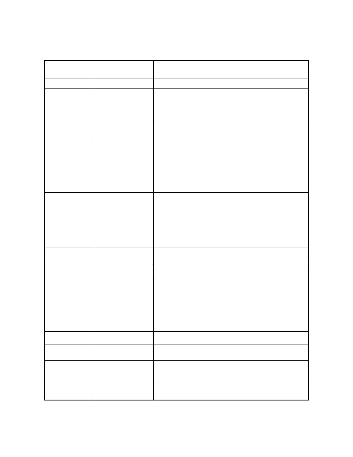
8. Function table
Function
Key Press
Description
JOG
[JOG]
Select JOG mode and enable the Wheel.
MARK CUE
[MARK]
Save the current time in the currently displayed Cue
RECORD
[REC]
Creates new clip and places Ki Pro into record
REWIND
[RWD]
Press RWD to Rewind Clip
4th press= 16x speed
Fast Forward
[FFWD]
Press FFWD to Fast Forward Clip
4th press= 16x speed
SLOMO
[SLOMO]
Not supported by Ki Pro
STOP
[STOP]
Press once to stop clip transport or exit record
Enter Search
[GOTO]
Search the Ki Pro to a specific time
Press [SHIFT/ESC] to exit without searching.
PLAY
[PLAY]
Press PLAY key to start transport
SHIFT/ESC
[SHIFT/ESC]
Pressing key will exit out of search time mode
Select Ki Pro
[1], [2], [3], [4]
Select which Ki Pro to control by pressing either [1], [2],
being controlled
EE Mode
[STOP]
Pressing “STOP” key twice will put AJA Ki Pro into EE
POINT
Point.
Mark only affects currently selected DDR. Cue points are
save in non-volatile memory.
*Note- pressing RWD more than once will put into the
following Reverse speeds:
st
1
press= 2X speed
nd
2
press= 4X speed
rd
3
press= 8X speed
*Note- pressing FFWD more than once will put into the
following Reverse speeds:
st
press= 2X speed
1
nd
2
press= 4X speed
rd
3
press= 8X speed
Time mode
For control
ST600-KIPRO User Manual Page 9 of 14
To enter a GOTO location without altering the contents
of the Cue Point, Press [SHIFT/ESC] + [GO TO]. Enter the
desired timecode using the designated keys with yellow
silkscreen. Press [GOTO] to search to the entered time.
[3] or [4]. Red LED will indicate which Ki Pro is currently
Page 10
Select a Cue
Point
[UP ARROW] ↑
Press either [↑] or [↓] to step through the Cue Points.
Or
[DOWN ARROW] ↓
Once desired cue point is shown on ST600 LCD, press the
[GOTO] key
*Maximum of 20 cue points per Ki Pro
ST600-KIPRO User Manual Page 10 of 14
Page 11
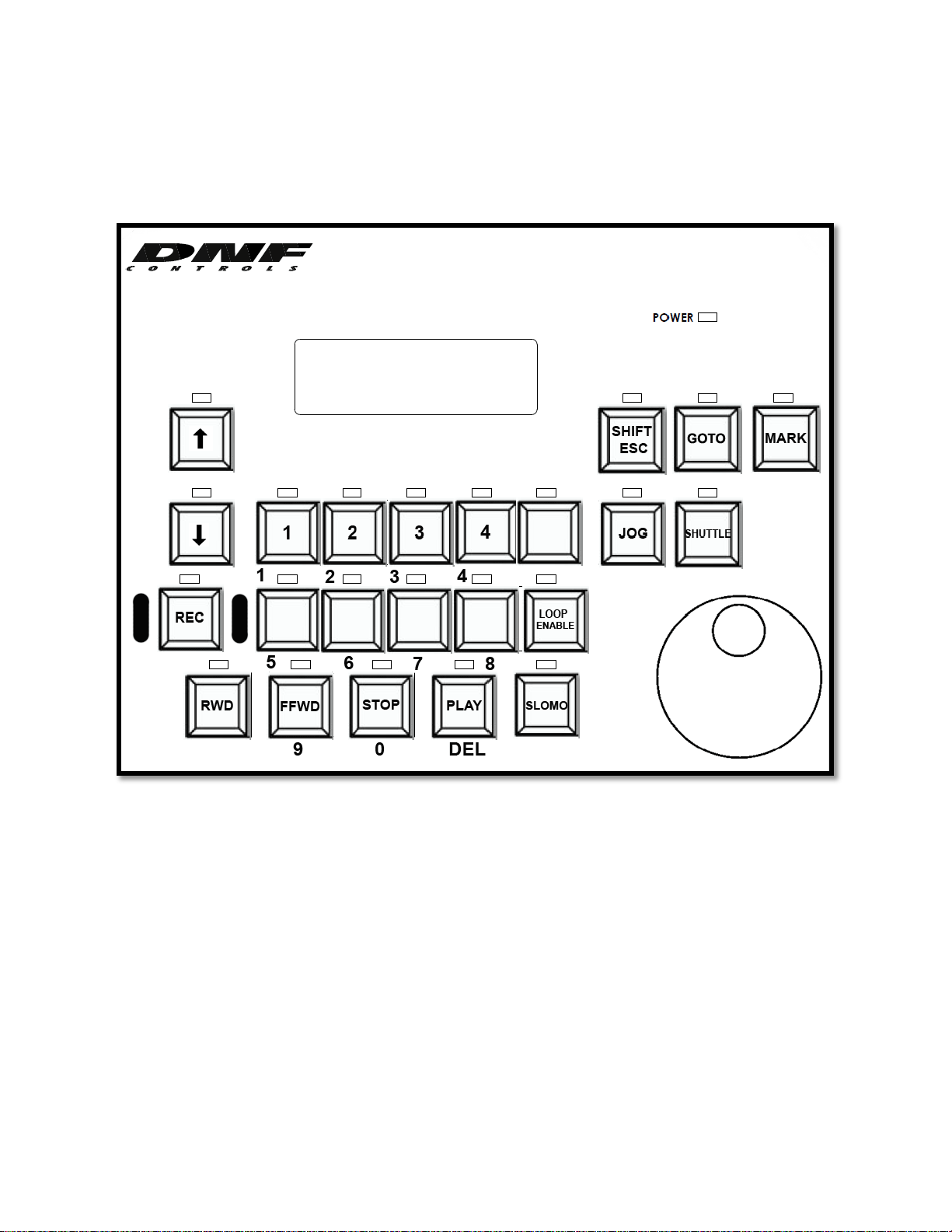
9. KEY LAYOUT
ST600-KIPRO User Manual Page 11 of 14
Page 12
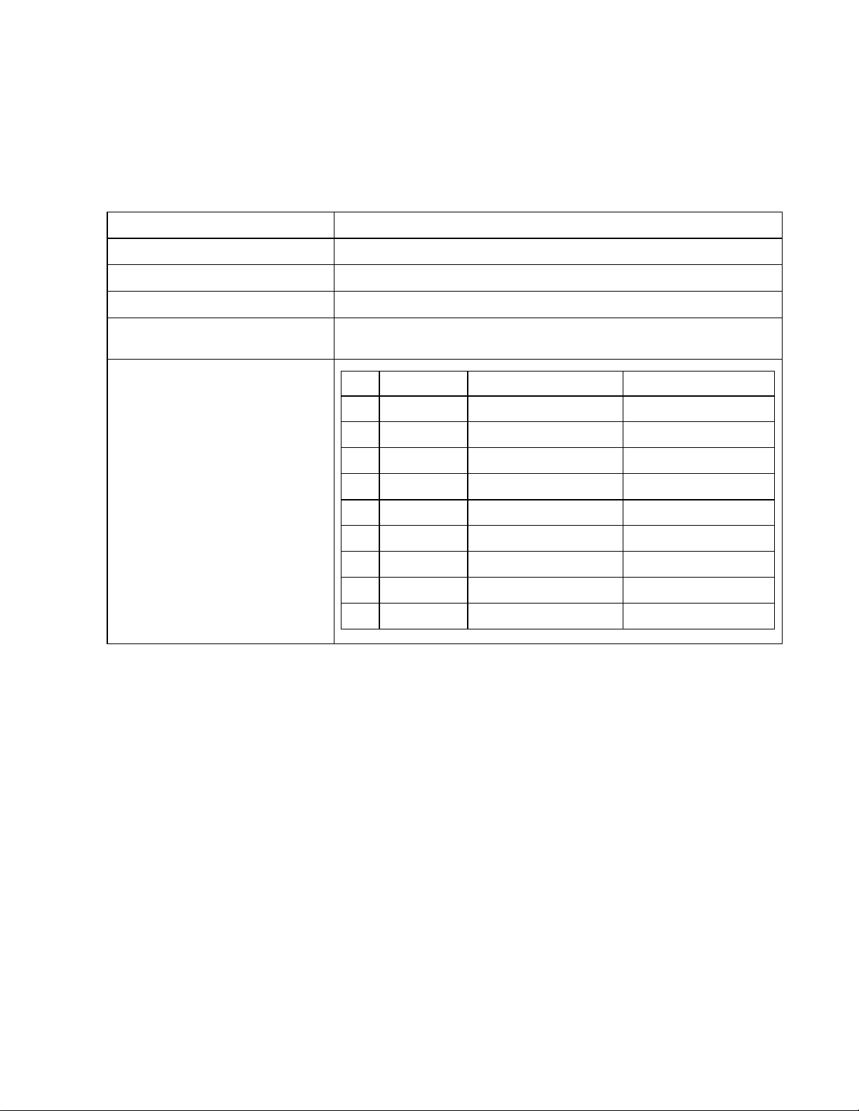
10. SPECIFICATIONS
1:
Switch:
ETHERNET:
Switch:
CONNECTOR:
Note: Serial and GPI/O connection are not supported at this time.
REAR PANEL CONNECTORS
SERIAL
POWER
RESET
S1
+12V DC, 3.33Amps (Max)
Press to reset USP3
RJ45 100baseT, Full Duplex
Press and hold 10 seconds to reset IP address to 192.168.10.217 and
configuration to factory default
RS232 DTE RS422 Controller RS422 Device
Pin
1
N/C
2
RxD Receive A (-) Transmit A (-)
3
TxD Transmit B (+) Receive B (+)
4
Tied to 6 Receive Common Receive Common
5
Ground N/C N/C
6
Tied to 4 Transmit Common Transmit Common
7
N/C Receive B (+) Transmit B (+)
8
N/C Transmit A (-) Receive A (-)
9
N/C Frame Ground Frame Ground
Frame Ground Frame Ground
ST600-KIPRO User Manual Page 12 of 14
Page 13
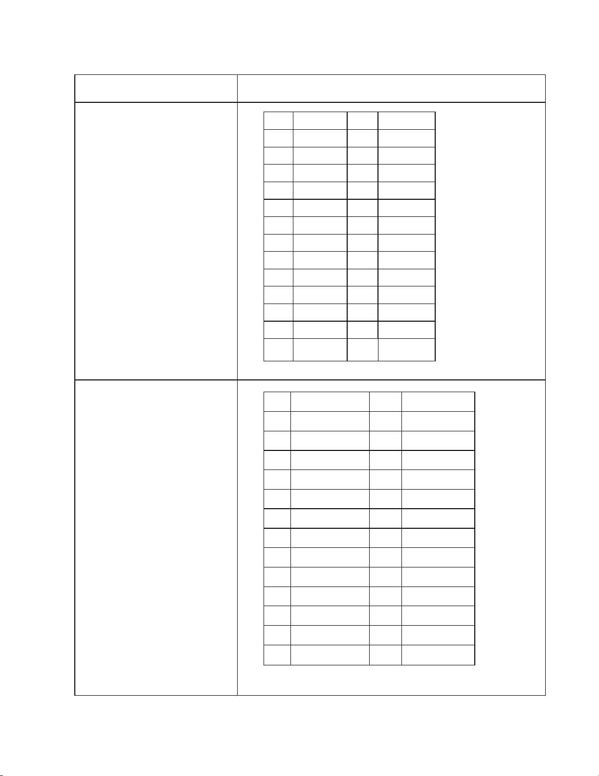
REAR PANEL DB25 CONNECTORS
GPI CONNECTOR 1-8:
Opto-isolator Inputs
NOTE:
GPI (+) is opto-isolator anode
GPI (-) is opto-isolator cathode
Pin # Description Pin # Description
1 Ground 14
GPI 8 +
2 GPI 8 ─ 15 +V
3 +V 16 GPI 7 ─
4
GPI 7 +
17
GPI 6 +
5 GPI 6 ─ 18 +V
6 +V 19 GPI 5 ─
7
GPI 5 +
20
GPI 4 +
8 GPI 4 ─ 21 +V
9 +V 22 GPI 3 ─
To WET GPIs:
Connect GPI + to nearby +V pin.
Connect GPI – to Ground to
turn on GPI.
GPI 3 +
10
11 GPI 2 ─ 24 +V
12 +V 25 GPI 1 ─
GPI 1 +
13
23
GPI 2 +
GPO CONNECTOR 1-8:
Isolated Relay
Contact Closures
Pin # Description Pin # Description
1 Common Bus 14 GPO 8 N.O
2 GPO 8 Common 15 Common Bus
3 Common Bus 16 GPO 7 N.O.
4 GPO 7 Common 17 GPO 6 N.O.
5 GPO 6 Common 18 Common Bus
6 Common Bus 19 GPO 5 N.O.
7 GPO 5 Common 20 GPO 4 N.O.
To WET GPOs:
Connect external power supply
output to Common Bus, pin #1.
Connect GPO commons to
8 GPO 4 Common 21 Common Bus
9 Common Bus 22 GPIO 3 N.O.
10 GPO 3 Common 23 GPO 2 N.O.
11 GPO 2 Common 24 Common Bus
nearby Common Bus pins
12 Common Bus 25 GPO 1 N.O.
There is no need to connect
connector
power supply Ground to GPO
13 GPO 1 Common
ST600-KIPRO User Manual Page 13 of 14
Page 14

11. DNF CONTROLS LIMITED WARRANTY
DNF Controls warrants its product to be free from defects in material and workmanship for a period of one (1) year
from the date of sale to the original purchaser from DNF Controls.
In order to enforce the rights under this warranty, the customer must first contact DNF’s Customer
Department to afford the opportunity of identifying and fixing the problem without sending
DNF’s Customer Support Department cannot fix the problem, the
Authorization number (RMA). The customer will
RMA number clearly indicated on the customer’s shipping document. The merchandise is to be shipped to:
DNF Controls
19770 Bahama St.
Northridge, CA. 91324
USA
Failure to obtain a proper RMA number prior to returning the product may result in the return not
or in a charge for the required repair.
DNF Controls, at its option, will repair or replace the defective unit. DNF Controls will return the unit prepaid to the
customer. The method of shipment is at the discretion of DNF Controls,
within the United States of America. Shipments to
require the product to be returned
account.
This warranty will be considered null and void if accident, misuse, abuse, improper line voltage, fire, water, lightning
or other acts of God damaged the product. All repair parts are to be supplied
through its authorized dealer network. Similarly, any repair
authorized dealer may void the warranty.
After the warranty period has expired, DNF Controls offers repair services at prices listed in the DNF Controls Price
List. DNF Controls reserves the right to refuse repair of any unit outside the
repairable.
DNF Controls shall not be liable for direct, indirect, incidental, consequential or other types of
from the use of the product.
in a more expeditious manner, the return shipment will be billed to their freight
then ship the defective product prepaid to DNF Controls with the
international customers will be sent via air. Should a customer
# # #
customer will be issued a Returned Merchandise
principally UPS Ground for shipments
by DNF Controls, either directly or
work not performed by either DNF Controls or its
warranty period that is deemed non-
Support
the unit in for repair. If
being accepted,
damage resulting
ST600-KIPRO User Manual Page 14 of 14
 Loading...