

Page 1

SYSTEM USER GUIDE
XT SERIES CONTROL PANEL
Page 2

Page 3

HOW TO HANDLE AN ALARM
Enter your user code or present your credential to the keypad if it has a built-in proximity reader. You will see:
IS THIS A FALSE ALARM? YES NO or CANCEL VERIFY
Press NO or VERIFY to notify to the emergency monitoring station.
Your system will remain armed.
Press YES or CANCEL to cancel the alarm.
Real Alarm
False Alarm
Your system will disarm.
Page 4

Page 5

TABLE OF CONTENTS
Get to Know Your System ................................... 3
Use Your Keypad .................................................. 5
LCD Keypad ......................................................................... 5
Graphic Touchscreen Keypad .......................................6
Using the Keypad ............................................................. 11
Know Your System Type ..................................... 13
Area ..................................................................................... 13
All/Perimeter ..................................................................... 13
Home/Sleep/Away .......................................................... 13
Arm Your System .................................................14
Area ...................................................................................... 14
All/Perimeter ..................................................................... 14
Home/Sleep/Away ..........................................................14
More Arming Options .................................................... 15
Disarm Your System ............................................16
How to Handle an Alarm .............................................. 16
Disarm Your System ....................................................... 16
Using Keyfobs ......................................................17
Arm ....................................................................................... 17
Disarm .................................................................................. 17
User Menu .............................................................18
Description of Each Option ......................................... 18
Access User Menu ........................................................... 19
User Check-In .................................................................... 19
Zone Activity Check ....................................................... 19
Sensor Reset ..................................................................... 19
Outputs On/O ...............................................................20
Favorite ..............................................................................20
Z-Wave Setup .................................................................. 23
Wi-Fi Setup ....................................................................... 25
Bypass Zones ................................................................... 26
Zone Monitor (Chime) .................................................. 26
System Test ........................................................................27
User Codes ........................................................................ 28
Schedules .......................................................................... 33
Date and Time .................................................................36
Display Events ................................................................. 36
Request Service? ............................................................36
Common Keypad Displays ................................ 37
Digital Monitoring Products, Inc. | XT30 and XT50 User Guide 1
Page 6

2 XT30 and XT50 User Guide | Digital Monitoring Products, Inc.
Page 7
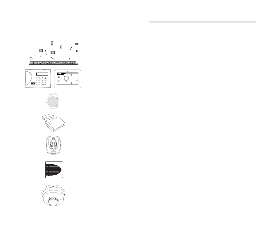
GET TO KNOW YOUR SYSTEM
Your system may not include all of the equipment and functions found in this guide.
J19 Celllular
Antenna
connection
J7 RJ
Supervision
J1
J3
Ethernet
Phone Line
OVC LED
RCV
Power
J8
LED
XMIT
Programming
J20
Wireless
Antenna
J24 Celllular
connection
header for
(XT50 only)
263G
TX RX
connection
Wireless LEDs
J18
Load
J16
Reset
Control Panel
J11
1
2
3
4
Outputs
The control panel acts as your system’s brain. It communicates with the keypad
and all the other system devices throughout the building.
FRI 2:52 PM
1 2 3 4
C
F
B
E
A
D
5 6 7 8
O
R
N
Q
M
P
9 0 CMD
Z
Y
CURRENT
82
HI LO
TODAY
98 77
I
L
H
K
G
J
HI LO
DISARMED
98 77
TUESDAY
X
U
W
T
V
S
R
E
K
T
C
N
A
E
B
Keypad
Panic
The keypad allows you to control your system from one place. You can use it
Chime
Reset
to arm and disarm your system, add user codes, verify alarms, and many other
Favorites
functions.
Prox Key
A prox key is an impact resistant credential that fits on a standard key ring. It
allows for codeless arming, disarming, and door access when it is presented to a
reader.
Sensor
Sensors are small devices that monitor motion, temperature, flooding, breaking
glass, and know when windows and doors have been opened.
Key Fob Remote
Depending on how your key fob remote is set up, it provides an easy way to arm
and disarm your system or send a panic alarm.
Siren
The siren emits sound when your system goes into alarm.
Smoke and Carbon Monoxide (CO) Detector
These detectors notify you when smoke or carbon monoxide is present. Some
detectors have an integrated synchronized sounder. If they are installed in groups,
they will all sound simultaneously.
Digital Monitoring Products, Inc. | XT30 and XT50 User Guide 3
Page 8
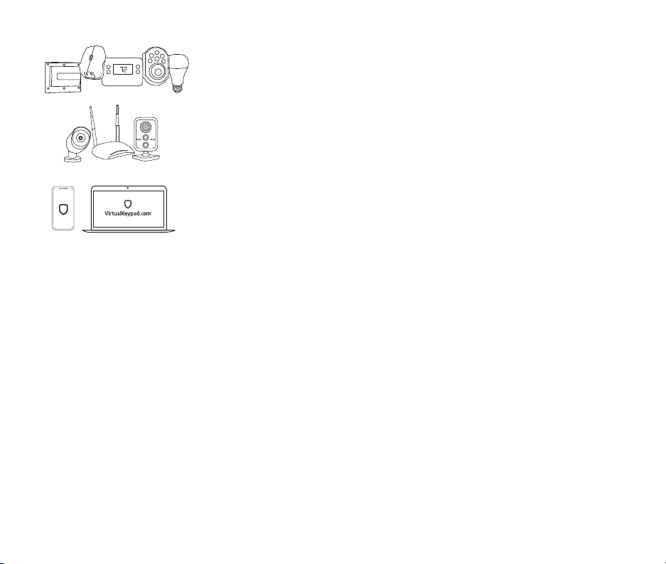
Z-Wave
TM
Z-Wave devices allow you to control the lights, small appliances, garage doors,
thermostats, and locks from the keypad, Virtual KeypadTM App, and VirtualKeypad.
com™.
SecureComTM Video
SecureCom Video allows you to add wired or wireless cameras inside or outside the
building. You can easily record clips or view live video feed at any time using the
Virtual Keypad App or VirtualKeypad.com.
Virtual Keypad App and VirtualKeypad.com
The Virtual Keypad App and VirtualKeypad.com allow you to control and monitor
your system on the go. The app is available for Apple® and Android™ devices.
4 XT30 and XT50 User Guide | Digital Monitoring Products, Inc.
Page 9
USE YOUR KEYPAD
Your system may have one or more LCD keypads that allow you to operate the system.
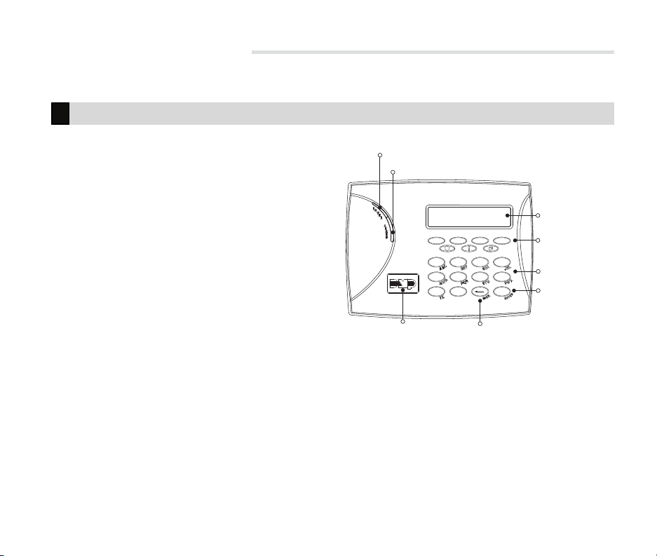
LCD Keypad
Proximity Card Reader
The keypad may have a built-in proximity card reader
that allows you to arm or disarm your system when
you present a credential.
Power and Armed LEDs
The AC Power and Armed LEDs indicate your system’s
power and armed status.
Select Keys
Use the select keys to type and navigate in the keypad.
Power
LED
Armed
LED
ABC PRINTING
FRI 2:51 AM
1 2 3 4
5 6 7 8
9 0 CMD
32-Character Display
Select Keys
Data Entry Digit Keys
CMD Key
Backlit Logo
and Proximity Antenna
Digital Monitoring Products, Inc. | XT30 and XT50 User Guide 5
Back Arrow Key
Page 10
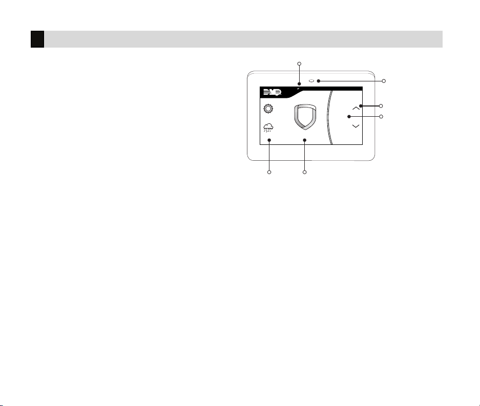
Graphic Touchscreen Keypad
Options
On the LCD keypad, press and hold the CMD and back
arrow keys at the same time to access the Options
Menu. On the Graphic Touchscreen Keypad, press
Options in the carousel menu. From here, you can
adjust the keypad brightness, tone, and volume.
Interactive Shield
On the Graphic Touchscreen Keypad, press the shield
to display your arming options. Disarm your system by
pressing the shield and entering your user code.
Carousel Menu
On the Graphic Touchscreen Keypad, use the
navigation arrows or press and drag to scroll through
the carousel menu options.
TODAY
TUESDAY
Local
Weather
System Status Icon
CURRENT
82
HI LO
98 77
HI LO
DISARMED
98 77
Interactive
Shield
Panic
Chime
Reset
Favorites
Proximity Card Reader
and Power/Armed LEDs
Navigation Arrows
Carousel Menu
6 XT30 and XT50 User Guide | Digital Monitoring Products, Inc.
Page 11

CAROUSEL MENU OPTIONS FOR GRAPHIC TOUCHSCREEN KEYPADS
Panic Press Police, Emergency, or Fire to send a panic report to the emergency monitoring station.
Chime Press Chime to turn the chime feature on and o. If chime is on, the keypad will sound an alert and
Reset Press Reset to reset fire and panic sensors after they have triggered an alarm.
Favorites Favorites displays a list of your Z-Wave favorites. Press a Favorite to activate it.
Options Press Options to display the Setting Options screen. From here, you can adjust the keypad screen
Keypad Press Keypad to display a standard DMP keypad. Use this option to access the User Menu.
User Codes Press User Codes to add, edit, or delete user codes in your system.
Schedules Press Schedules to add, edit, or delete schedules. You can also use it to assign schedules to outputs and
Events Events allows you to view up to 12,000 past events that occurred on your system over the last 45 days.
Thermostats Press Thermostats to display the Z-Wave thermostats screen. From here, you can adjust the temperature
Doors Press Doors to lock or unlock Z-Wave locks. You can also open and close Z-Wave-equipped garage doors.
Lights Press Lights to turn ON, turn OFF, or DIM Z-Wave lights.
display a notification when external doors and windows (with sensors installed) are opened.
brightness, tone, and volume. You can also choose what you want to display in the carousel menu.
favorites, as well as auto-arming and auto-disarming.
or select ON, OFF, HEAT, COOL, or FA N.
Digital Monitoring Products, Inc. | XT30 and XT50 User Guide 7
Page 12

System Status Icons
System status icons for the Graphic Touchscreen keypad are located at the top of your home screen. The following
icons indicate the status of your system:
System Ready to Arm
The check mark indicates that your system is ready to arm. If you don’t see the check mark, a door or
window may be open.
Attention List
When pressed, the attention list icon displays the type of event or trouble message your system has
recorded. It also shows the name and number of any aected zones.
Battery Trouble
If you see this icon, your system’s battery is low or disconnected.
Chime On
This icon means your chime is turned on. A tone will sound each time a door or window is opened. You
can activate this feature in the Chime section of the user menu.
AC Power Trouble
If you see this icon, your system’s isn’t receiving AC power.
Wi-Fi Connection
If you see this icon, your system is connected to a Wi-Fi network.
8 XT30 and XT50 User Guide | Digital Monitoring Products, Inc.
Page 13

Weather
Your system has been programmed to provide local weather information based on your zip code. Current weather
conditions and forecasted HI and LOW temperatures are available on the home screen.
Security Provider Logo
Press the logo at the top of the keypad to bring up your security provider’s contact information.
Power/Armed LED
The LED at the top-center of the keypad indicates the keypad’s power status and your system’s arming status.
Depending on the status, the LED will be red or blue. See the table below for more information.
COLOR AND ACTIVITY ARMED STATUS KEYPAD POWER STATUS
Blue Steady Disarmed AC Power OK, Battery OK
Blue Blinking Disarmed AC Power OK, Battery Trouble
No Light Disarmed AC Power Trouble, Battery OK
Red Steady Armed AC Power OK, Battery OK
Red/Blue Alternate Armed AC Power OK, Battery Trouble
Red Blinking Armed AC Power Trouble, Battery OK
Digital Monitoring Products, Inc. | XT30 and XT50 User Guide 9
Page 14

Proximity Card Reader
Your keypad provides a built-in proximity card reader located behind the power/armed LED. Present your proximity
card or keyfob here to disarm your system.
Interactive Shield
The interactive shield allows arming and disarming from the home screen. Depending on your system type, you will
see either the All/Perimeter or Home/Sleep/Away options when you press the shield to arm your system.
All
This arming type arms both the perimeter and the interior of your home. Use this when you are leaving
the house and no one will remain inside.
Perimeter
This arming type arms just the perimeter of your home. Use this when you are staying home, but would
like to arm your exterior doors and windows.
Home
This arming type arms the perimeter of your home. Use this when you are staying home, but would like to
arm your exterior doors and windows.
Sleep
This arming type arms the perimeter of your home, as well as a portion of the interior. Bedrooms and
nighttime parts of your home are left unarmed, allowing you to access parts of your home during the
night. Other areas of the house that are not used at night are armed.
Away
This arming type arms the perimeter, interior, and bedrooms. Use this when you are leaving the house
and no one will remain inside.
10 XT30 and XT50 User Guide | Digital Monitoring Products, Inc.
Page 15

Using the Keypad
Command (CMD)
Use CMD to move forward through each section of the user menu. You can also press CMD to save information you
have just entered.
Back Arrow
Use the back arrow to back up one step while in the user menu. You can also press the back arrow once to erase
the last character you entered.
Select Areas
Your keypad has a top row of select areas. Each time you press a select area, the keypad displays a function or
series of options.
When there are more than four options avail able, press CMD to display the remaining options. Pressing the back
arrow allows you to review the previous four choices.
Standard Keyboard
• Press ABC to enter uppercase letters.
• Press abc to enter lowercase letters.
• Press !@# to enter symbols.
• Press 123 to enter numbers and to return to
the number pad.
Standard Keyboard
Digital Monitoring Products, Inc. | XT30 and XT50 User Guide 11
Page 16

Number Pad
1. Choose a letter or symbol from the table.
2. Identify the correlating number key and enter
it in the keypad.
3. Identify the select area for that number and
press that select area on the keypad.
4. When your letter or symbol displays on the
keypad, return to Step 1 or press CMD if you
are finished.
Number Pad
NUMBER
SELECT AREA
1 2 3 4
1 A B C ( [ {
2 D E F ) ] }
3 G H I ! ^ ~
4 J K L ? “ |
5 M N O / \ `
6 P Q R & $
7 S T U @ %
8 V W X , =
9 Y Z Space : _ ;
0 - + . ‘ * < # >
12 XT30 and XT50 User Guide | Digital Monitoring Products, Inc.
Page 17

KNOW YOUR SYSTEM TYPE
Your system operates in one of the following ways:
Area
In an Area (A) system, your burglary protection is divided into up to six areas. Each area can have a custom name,
be turned on or o, and limit access to only those users with proper authority.
All/Perimeter
In an All/Perimeter (All Perim) system, the building is divided into 2 main areas:
All
Arms both the perimeter and interior.
Use when no one is inside.
Perimeter
Arms just the perimeter of the building.
Use when you’re inside.
Home/Sleep/Away
In a Home/Sleep/Away (H S A) system, the building is divided into 2 or 3 areas: perimeter, interior, and bedrooms.
Home
Arms the perimeter.
Use when you’re inside.
Sleep
Arms the perimeter and a portion of the interior.
Use to leave the bedroom areas unarmed.
Away
Arms the perimeter, interior, and bedrooms.
Use when no one is inside.
Digital Monitoring Products, Inc. | XT30 and XT50 User Guide 13
Page 18

ARM YOUR SYSTEM
Area
1. Press and release the shield on a Graphic Touchscreen Keypad to open the arming options screen or press
CMD on an LCD Keypad until ARM DISARM displays.
2. Select ARM. The keypad displays ALL? NO YES.
3. To arm all areas, select YES. To arm selected areas, select NO. The keypad displays each area you have
access to. Select YES to arm the areas and NO to leave the area disarmed.
All/Perimeter
1. Enter your user code and the keypad displays PERIM ALL.
2. Select ALL to arm all areas. The keypad displays ALL SYSTEM ON. Select PERIM to arm only the perimeter.
The keypad displays PERIMETER ON.
Home/Sleep/Away
1. Enter your user code and the keypad displays H S A.
2. Select HOME if you’re staying inside the building, leaving the interior disarmed and arming the exterior.
Select SLEEP to leave the bedroom areas disarmed, arming the interior and exterior areas. Select AWAY if
no one will remain inside the building. Select GUEST to arm the guest areas.
14 XT30 and XT50 User Guide | Digital Monitoring Products, Inc.
Page 19

More Arming Options
Instantly Arm Your System
1. Press and release the shield on a Graphic Touchscreen Keypad to open the arming options screen or press
CMD on an LCD keypad until ARM DISARM displays.
2. Select INSTANT. This overrides the entry and exit delay, instantly arming your system.
Bypass Zones
If a problem exists on any zone, the zone name and problem display, followed by OKBYPASSSTOP.
• Press OK to force arm the zone. The zone will re-arm when it’s restored.
• Press BYPASS to ignore the zone before arming. Panic, emergency, fire, flood detector, and temperature
sensor zones cannot be bypassed.
• Press STOP to stop your system from arming. This allows you to correct the zone, return to the keypad,
and restart the arming process.
Extend Schedules
When a schedule is active, you can extend the schedule to a later time. When arming your system, the keypad
displays LATE or CLOSING TIME!.
1. Press any select key or area. The keypad displays ENTER CODE.
2. Enter your user code and press CMD or present your credential to a card reader.
3. The keypad displays 2HR 4HR 6HR 8HR. Select the number of hours to extend the schedule.
Note: Panic, emergency, fire, flood detector, and temperature sensor zones cannot be bypassed.
Digital Monitoring Products, Inc. | XT30 and XT50 User Guide 15
Page 20

DISARM YOUR SYSTEM
How to Handle an Alarm
Enter your user code or present your credential to the keypad if it has a built-in proximity reader. You will see:
IS THIS A FALSE ALARM? YES NO or CANCEL VERIFY
Real Alarm
Press NO or VERIFY to notify the emergency monitoring station. Your system will remain armed.
False Alarm
Press YES or CANCEL to cancel the alarm. Your system will disarm.
Disarm Your System
1. Press the shield on the Graphic Touchscreen Keypad and enter your user code to disarm your system or
press CMD on the LCD Keypad until ARM DISARM displays.
2. Select DISARM. The keypad displays ALL? NO YES.
3. Select YES to disarm all areas. Select NO to disarm individual areas and select YES to disarm the area or
NO to leave the area armed.
16 XT30 and XT50 User Guide | Digital Monitoring Products, Inc.
Page 21

USING KEYFOBS
Arm
Press the key fob button programmed for Arming or Toggle (Arm/Disarm) button. A Red LED two-second
acknowledgement indicates All System On. A Green/Red two-second acknowledgement indicates System On with
some areas armed.
Disarm
Press the key fob button programmed for Disarming or Toggle (Arm/Disarm) button. A Green LED two-second
acknowledgement indicates All System O.
Digital Monitoring Products, Inc. | XT30 and XT50 User Guide 17
Page 22

USER MENU
Description of Each Option
USER CHECKIN
Check-in with the system to indicate arrival on
premises.
ZONE ACTIVITY CHECK
Monitor a zone for non-activity.
This could be used for a person living alone to detect
when they have not moved about to trip a disarmed
zone within a programmed period of time. This feature
is optional.
The Zone Activity Check is disabled when a
schedule is entered to allow for sleeping hours and is
automatically enabled when an area is disarmed.
SENSOR RESET
Resets smoke or glassbreak detectors that have
latched during an alarm condition.
OUTPUTS ON/OFF
Turn on or o outputs.
FAVORITES
Activate Favorites.
A maximum of 25 devices can be assigned to each
Favorite.
Z-WAVE SETUP
Add, List, Remove, Transfer, and Optimize Z-Wave
devices in your system. You can create Z-Wave
Favorites, Add, Edit, and Remove Z-Wave devices in
Favorites.
A maximum of 140 Z-Wave devices can be added to
the system.
18 XT30 and XT50 User Guide | Digital Monitoring Products, Inc.
WIFI SETUP
Add, remove, or test Wi-Fi service when using the
Optional Wi-Fi Module.
BYPASS ZONES
Bypass a zone or reset an already bypassed zone.
ZONE MONITOR
Add or remove a zone from the monitor mode.
SYSTEM TEST
Tests the system siren, communication to the central
station, and backup battery.
USER CODES
Add, delete, or change user codes and authority levels.
SCHEDULES
Add, remove, or change system schedules.
DATE AND TIME
Change the Day, Date, or Time that is currently in the
system.
DISPLAY EVENTS
View the last 100 events on the XT30 and 200 events
on the XT50 that occurred on your system.
SERVICE REQUEST
Send a message to the Central Station requesting
service on the alarm system.
Page 23

Access User Menu
1. Press the CMD key until MENU? NO YES displays.
2. Select YES. The keypad displays ENTER CODE. Enter your user code. You can now scroll down through the
list of system features available to you.
User Check-In
1. Access the User Menu.
2. At USER CHECKIN, press any select key or area. The keypad displays USER CHECKIN: 22 (22 = user
number).
3. The panel sends the Check-in Report containing your account number and user number to the email
address or cell phone number.
Zone Activity Check
1. Access the User Menu.
2. At ACTIVITY CHECK?, press any select key or area. The keypad displays ENABLE? YES NO. The default is
YES.
3. When NO is selected, the keypad displays CHECK DISABLED for four seconds and then sends the Activity
Check Disabled message to the central station.
4. When YES is selected, the keypad displays CHECK ENABLED for four seconds and then sends the Activity
Check Enabled message to the central station.
Sensor Reset
1. Access the User Menu.
2. At SENSOR RESET?, press any select key or area. The keypad displays SENSORS OFF for five seconds
followed by SENSORS ON.
3. The keypad returns to the status display.
Digital Monitoring Products, Inc. | XT30 and XT50 User Guide 19
Page 24

Outputs On/O
1. Access the User Menu.
2. At OUTPUTS ON/OFF?, press any Select Key or Area. The keypad displays OUTPUT:-ONOFF.
3. Press any select key or area.
4. Enter the output number, then select ON or OFF.
Favorite
Activating a Favorite
1. Access the User Menu.
2. At FAVORITES?, press any Select Key or Area. The keypad displays FAVORITE.
3. Enter a Favorite number from 1-20. Pressing CMD activates the Favorite.
Adding a Favorite
1. Access the User Menu.
2. At ZWAVESETUP?, press any Select Key or Area. The keypad displays ADDLISTREMOVE.
3. Press CMD again to display FAV XFER OPT. Select FAV and FAVORITE NUMBER is displayed.
4. Enter a Favorite number between 1 and 20 and press CMD. If the Favorite number entered is unassigned,
*UNUSED* displays. If the Favorite is already assigned, you may change the name or press the back arrow
and enter a new number.
5. Press any select key or area and a cursor displays. Enter a Favorite name up to 16 characters. To remove a
Favorite, press CMD without entering a name.
6. Press CMD to save the Favorite and the Favorite name and ADDEDITREMOVE displays.
20 XT30 and XT50 User Guide | Digital Monitoring Products, Inc.
Page 25

Add Devices to Favorites
1. Access the User Menu.
2. At ZWAVESETUP?, press any Select Key or Area. The keypad displays ADDLISTREMOVE.
3. Press CMD again to display FAVXFEROPT. Select FAV.
4. When ADD DEL CHG displays, select ADD.
5. When FAVORITE NUMBER is displayed, enter a Favorite number between 1 and 20 and press CMD.
6. The Favorite number displays. Press any top row Select Key or Area and enter a Favorite Name.
7. Press CMD and the Favorite Name and ADD EDIT REMOVE displays.
8. Select ADD.
9. Press CMD to browse your Z-Wave devices.
10. Press any Select Key or Area to assign a device to a Favorite.
Program Devices in Favorites
Lights
Press any Select Key or Area at SETTING and ON OFF DIM displays. Press the Select Key or Area under the desired
setting.
• Select ON or OFF to turn a device on or o.
• Select DIM, enter the dim level (1-10) of the device, and press CMD.
Doors
• Doors: Press the select key or area for the desired setting when SETTING: LOCK UNLOCK displays
• Garage Doors: Press the select key or area for the desired setting when SETTING: OPEN CLOSE displays.
Thermostats
O
Select OFF to display FAN SETTING. Press any select key or area. When ON AUTO displays, press the select key
for the desired option.
Cool
Select CL and press any select key or area. Enter the new temperature and press CMD.
Heat
Select HT then press any select key or area. Enter the new temperature and press CMD.
Digital Monitoring Products, Inc. | XT30 and XT50 User Guide 21
Page 26

Edit Devices in Favorites
1. Access the User Menu.
2. At ZWAVESETUP?, press any Select Key or Area. The keypad displays ADDLISTREMOVE.
3. Press CMD again to display FAVXFEROPT. Select FAV.
4. At ADD DEL CHG, select CHG.
5. At FAVORITE NUMBER, enter a Favorite number between 1 and 20 and press CMD.
6. The Favorite number and name displays. Press CMD and the Favorite Name and ADDEDITREMOVE
displays.
7. Select EDIT.
8. Press CMD to browse your Z-Wave devices.
9. Press any select key or area to view a device’s settings. Refer to the Lights, Doors, and Thermostat sections
on this page to edit your devices.
Remove Devices from Favorites
1. Access the User Menu.
2. At ZWAVESETUP?, press any Select Key or Area. The keypad displays ADDLISTREMOVE.
3. Press CMD again to display FAVADDDELCHG displays. Select DEL.
4. When FAVORITE NUMBER is displayed, enter a Favorite number between 1 and 20 and press CMD.
5. The Favorite number and name displays. Press CMD and the Favorite Name and ADDEDITREMOVE
displays.
6. Select REMOVE and the first Z-Wave device stored in the Favorite displays. Remaining devices can be
viewed by pressing the CMD key.
7. Press any Select Key or Area to remove the device from the Favorite. REMOVEDEVICEFROMFAV? NO YES
displays. When YES is selected, the device is removed from the Favorite.
22 XT30 and XT50 User Guide | Digital Monitoring Products, Inc.
Page 27

Z-Wave Setup
Add Z-Wave Devices
1. Press the CMD key until MENU?NOYES displays.
2. Select YES. The keypad displays ENTER CODE. Enter your user code. Press CMD to scroll to
ZWAVESETUP?.
3. Press any Select Key or Area. The keypad displays ADDLISTREMOVE.
4. Select ADD.
5. Press the button on the Z-Wave device when PRESS BUTTON ON DEVICE TO ADD displays on the keypad.
6. Press CMD when DEVICE FOUND displays.
7. Press any top row select key or area and name the device.
8. Press CMD to save the device.
Rename Z-Wave Devices
1. Access the User Menu.
2. At ZWAVESETUP?, press any Select Key or Area. The keypad displays ADDLISTREMOVE.
3. Select LIST. Press the CMD key to advance through the list of Z-Wave devices.
4. Press any Select Key or Area to display DEVICE RENAME STATUS.
5. Select RENAME and enter a new device name.
6. Press CMD to save the new Z-Wave device name.
Status of Z-Wave Devices
1. Access the User Menu.
2. At ZWAVESETUP?, press any Select Key or Area. The keypad displays ADDLISTREMOVE.
3. Select LIST to display DEVICE LIST and the first Z-Wave device stored. Press the CMD key to advance
through the list of Z-Wave devices.
4. Press any Select Key or Area to display DEVICE RENAME STATUS.
5. Select S TATU S. The device name and OKAY display when the device communicates. The device name and
FAILED display if the device stored in the system does not communicate.
6. Press CMD and REMOVE FAILED DEVICE displays.
7. Select YES to remove the failed device from your system. Select NO to leave the device in your system.
Digital Monitoring Products, Inc. | XT30 and XT50 User Guide 23
Page 28

Remove Z-Wave Devices
1. At ZWAVESETUP?, press any Select Key or Area. The keypad displays ADDLISTREMOVE.
2. Select REMOVE.
3. Press the button on the Z-Wave device when PRESS BUTTON ON DEVICE TO REMOVE displays on the
keypad.
Transfer Controller
This option allows the transfer of all existing Z-Wave devices that are currently programmed in another
manufacturer’s Z-Wave portable controller to your system.
Note: This operation will overwrite all Z-Wave devices that are programmed in your system.
Initiate the transfer at the other manufacturer’s Z-Wave portable controller after starting the transfer on the
DMP keypad. Z-Wave devices are not overwritten until the transfer has been initiated at the other manufacturer’s
Z-Wave portable controller. The transfer should not be stopped once the process has been initiated from the other
manufacturer’s Z-Wave portable controller.
1. At ZWAVE SETUP?, press any Select Key or Area. The keypad displays ADDLISTREMOVE.
2. Press CMD again to display FAVXFER OPT.
3. Select XFER. The keypad warns you that transferring Z-Wave device information deletes all your Z-Wave
devices connected to your system.
4. Select YES to proceed.
5. Initiate the transfer at the other manufacturer’s Z-Wave portable controller. ZWAVE SETUP? displays.
Optimize
This updates communication with all Z-Wave devices. It can be used to re-establish communication after a Z-Wave
device has been moved to a dierent location. Z-Wave devices that fail to communicate during the optimize
process are not removed from panel programming.
1. At ZWAVESETUP?, press any Select Key or Area. The keypad displays ADDLISTREMOVE.
2. Press CMD to display FAVXFEROPT.
3. Select OPT. The keypad displays OPTIMIZE.
4. The keypad will display OPTIMIZESUCCESS when Z-Wave devices have been retrieved.
24 XT30 and XT50 User Guide | Digital Monitoring Products, Inc.
Page 29

Wi-Fi Setup
Use WPS to Connect Your System
1. Press the WPS button on the Wi-Fi network router to start the pairing operation.
2. Press the CMD key until MENU?NOYES displays.
3. Select YES. The keypad displays ENTER CODE. Enter your user code. Press CMD to scroll to WIFISETUP?.
4. Press any Select Key or Area. The keypad displays WPSLISTMANUAL.
5. Select WPS. When WPS is successful, CONNECTED displays. If WPS is unsuccessful,
WPSFAILEDRETRY?NOYES displays. Press YES to retry. Press NO and WPS LIST MANUAL displays.
List the Available Networks
1. At the WPSLISTMANUAL display, select LIST and SEARCHING displays.
2. Press CMD to view the available Wi-Fi networks.
3. When the desired network displays, press any select key or area to connect. W/L KEY:****************
displays.
4. If the system is unable to detect the security type, press any select key or area on the keypad and WEP
WPA NONE displays. Select the desired security type and enter your network password.
Manually Connect Your System
1. At the WPSLISTMANUAL display, select MANUAL.
2. Enter the name of your Wi-Fi network and press CMD. W/L KEY:**************** displays.
3. If the system is unable to detect the security type, press any select key or area on the keypad and WEP
WPA NONE display. Select the desired security type then enter your network password.
Test the Network Connection
1. Select TEST. When the test is successful, CONNECTED displays. If the test is unsuccessful, NOT
CONNECTED displays.
2. Press CMD to return to WIFISETUP?.
Digital Monitoring Products, Inc. | XT30 and XT50 User Guide 25
Page 30

Bypass Zones
1. Press the CMD key until MENU?NOYES displays.
2. Select YES. The keypad displays ENTER CODE. Enter your user code. Press CMD to scroll to BYPASS
ZONES?.
3. Press any Select Key or Area. The keypad displays ZONE - RST BYPS.
• To reset a zone, enter the zone number and select RST. Confirmation will be given when the zone is
reset.
• To bypass a zone, enter the zone number and select BYPS. Confirmation will be given when the zone
is bypassed.
Zone Monitor (Chime)
1. Press the CMD key until MENU?NOYES displays.
2. Select YES. The keypad displays ENTER CODE. Enter your user code. Press CMD to scroll to
ZONEMONITOR?.
3. Press any Select Key or Area. The keypad displays PERIM ALL NBR.
4. Select PERIM to place all perimeter zones into Zone Monitor.
4a. The keypad displays PERIM? ADD RMV.
4b. Select ADD to add all perimeter zones to Zone Monitor.
4c. Select RMV to remove all perimeter zones.
5. Select ALL to place all zones into Zone Monitor.
5a. The keypad displays ALL?ADDRMV.
5b. Select ADD to add all Night and Exit zones to Zone Monitor.
5c. Select RMV to remove all Night and Exit zones.
6. Select NBR to enter a specific zone number for zone monitor.
7. If NBR is selected, the keypad displays ZONE : - ADD RMV.
7a. Enter any zone number and select ADD to add this zone.
7b. Enter any zone number and select RMV to remove the zone.
8. The zone number automatically disappears and a new zone number can then be entered. See step 7.
26 XT30 and XT50 User Guide | Digital Monitoring Products, Inc.
Page 31

System Test
1. Press the CMD key until MENU?NOYES displays.
2. Select YES. The keypad displays ENTER CODE. Enter your user code. Press CMD to scroll to SYSTEM
TEST?.
3. Press any Select Key or Area. The system test begins automatically and the keypad displays:
• BELL SOUNDING during a two second bell test
• KEYPAD SOUNDING during a two second keypad test
• BATTERY - OKAY or BATTERY- TRBL to indicate the battery condition
• TRANSMIT TEST * and ATTEMPT NO : 1 during the transmit test
• TRANSMIT OKAY or TRANSMITFAILED to show the transmit test results
• TEST END to indicate the System Test is complete.
4. Press the Back Arrow key to end the system test.
* The transmit test does not occur on local systems.
Testing Your System Burglary Protection:
The System Test function should be part of your weekly testing and should be followed by placing the interior and
perimeter burglary devices in Zone Monitor mode. This allows you to open and then close each protected door and
window while listening for the keypad to beep confirming its operation.
Digital Monitoring Products, Inc. | XT30 and XT50 User Guide 27
Page 32

User Codes
There are three characteristics associated with each user code that define its capabilities within the system.
CHARACTERISTIC EXAMPLE
User Number 22
User Code 3848
Authority Level Master
User Number
Each user is numbered from 1 to 30 in an XT30 or 1 to 99 in an XT50 panel. This number identifies them to the system
and can be transmitted to the central station when they arm or disarm the system.
User Code
Users also have a 4-digit user code they enter into the keypad when arming or disarming. This user code is kept secret
from other users and is not transmitted to the central station when they arm or disarm. Users enter only their own user
code when operating the system.
User Names
Each code may also be programmed with the user name. You may enter up to 16 characters for the name. The user
is also assigned a level of authority (Master, Standard, Limited, or Scheduled) by the person administrating the
system to determine the functions the user can access. The XT30 allows Master and Standard users while the XT50
allows all levels of authority.
The Scheduled authority level only functions during a valid schedule, except for arming which can be done at any
time. Disarming is allowed outside of a schedule, but an UNAUTHORIZED ENTRY message is sent to the central
station. All other authority levels function regardless of schedules.
The next table lists system functions users are allowed to access based on the authority level assigned to their
codes at the time they are added to the system.
28 XT30 and XT50 User Guide | Digital Monitoring Products, Inc.
Page 33

USER MENU OPTION
Door Access
Arm and Disarm
Alarm Silence
User Checkin
Zone Activity Check
Sensor Reset
Outputs On/O
Favorites
Z-Wave Setup
Wi-Fi Setup
Bypass Zones
Zone Monitor
System Test
User Codes
Schedules
Extend
Set Time
Display Events
Service Request?
SCHEDULED
(XT50 ONLY)
✔ ✔ ✔ ✔
✔ ✔ ✔ ✔
✔ ✔ ✔ ✔
✔ ✔ ✔ ✔
✔ ✔ ✔ ✔
✔ ✔ ✔ ✔
✔ ✔ ✔ ✔
✔ ✔ ✔ ✔
LIMITED
(XT50 ONLY)
✔ ✔ ✔
✔ ✔ ✔
✔ ✔ ✔
STANDARD
(XT30/XT50)
✔ ✔
✔ ✔
MASTER
(XT30/XT50)
✔
✔
✔
✔
✔
✔
Digital Monitoring Products, Inc. | XT30 and XT50 User Guide 29
Page 34

Adding User Codes
1. Press the CMD key until MENU?NOYES displays.
2. Select YES. The keypad displays ENTER CODE. Enter your user code. Press CMD to scroll to
USERCODES?.
3. Press any Select Key or Area. The keypad displays ADD DEL CHG.
4. Select ADD to add a new user code.
5. At the USER NUMBER prompt, enter a user number and press CMD.
6. The displays changes to CODE NO. Enter the four-digit user code and press CMD.
7. A 16-character name may be entered to identify the user. Press any top row key to clear the current text
“user name”. You may then enter the new name. After entering the name press CMD.
8. For XT30 Panels:
The display changes to MASTER?NOYES.
8a. Select YES to make this a Master user level with the authority to access all User Menu functions.
8b. Select NO to make this a Standard user level. Default is set to NO. Proceed to step 9a.
For XT50 Panels:
The display changes to LEVEL:STANDARD.
8a. Press any Select Key or Area. The keypad displays SCHLTDSTDMSTR.
8b. Select the authority level to assign to the user code.
9. The following options can be selected for user codes with non-Master authority levels:
9a. TEMP CODE NO YES.
Select NO to make this a permanent user code.
Select YES to make this a temporary code. The keypad displays TEMPDAYS: -. Enter the number
of days (1 to 250) that the temporary use code can operate. Default is seven days. Temporary
users are deleted from the system at 12:00 AM on the last day. You can delete a Temporary user
code at any time before the programmed period ends.
9b. AREAS: (Displays in Area systems only).
Enter the area numbers where this user is to have access. For example: if you want this user to
only have access to areas 1 and 2, enter the numbers 1 and 2. Once the correct area numbers
display, press CMD.
9c. ARM ONLY NO YES. Select NO to allow this user to arm and disarm the system and access all
Standard level functions in the User Menu. Select YES to restrict this user toarming only. The Arm
Only user code can bypass zones not in a normal condition at the time of arming.
30 XT30 and XT50 User Guide | Digital Monitoring Products, Inc.
Page 35

10. At the USER CODE IN LOCK? NO display, choose whether or not the user code is stored in all compatible
Z-Wave Doors. Press the third top row Select Key or Area for NO or the fourth top row Select Key or Area
for YES. Then, press CMD.
Note: This option is only available for user codes 2-20. Once the user code has been received by the
lock, entering it at the lock will lock the door or unlock the door and disarm the system depending
on the user’s privileges.
11. After you complete your selections, the keypad displays USER#ADDED.
12. Press the Back Arrow key once to add another user or twice to exit the User Menu.
Digital Monitoring Products, Inc. | XT30 and XT50 User Guide 31
Page 36

Changing Your Own User Code
1. At USERCODES?, press any Select Key or Area. The display changes to USERCODE?CODENO: ******.
2. Press any Select Key or Area. The user code is erased and display changes to CODE NO.
3. Type your new user code. Press CMD. Display will show USERXXXXCHNGD to confirm the change.
Changing User Codes
1. At USERCODES?, press any Select Key or Area. The keypad displays ADDDELCHGSEND.
2. Select CHG to change a user code.
3. At the USER NUMBER prompt, enter the user number to change and press CMD.
4. The display changes to CODENO:****. Enter the new user code.
If the code you entered is already in use, or is a code used internally by the system, the keypad displays
ALREADY IN USE. You must enter a dierent 4-digit user code.
5. The display then shows the current user name. Press any top row key to clear.
6. If you are changing a code other than your own, the keypad next displays LEVEL?.
7. Press any Select Key or Area. The keypad displays SCHLTDSTDMSTR.
Note: Changing a user code does not change the user number. User number 2 may have their user code
changed from 1234 to 5678 but they are still user number 2.
Deleting User Codes
1. At USERCODES?, press any Select Key or Area. The keypad displays ADDDELCHGSEND.
2. Select DEL to delete a user code from the system.
3. At the USER NUMBER prompt, enter the user number you want to delete and press CMD. The display
changes to USER # DELETED.
4. The display then changes back to USER NUMBER for you to delete another user. Press the Back Arrow key
twice to exit the User Menu.
32 XT30 and XT50 User Guide | Digital Monitoring Products, Inc.
Page 37

Schedules
Permanent Schedules
Permanent schedules are used for automatic arming and disarming and always occur at the same time until you
change or delete them.
1. Press the CMD key until MENU?NOYES displays.
2. Select YES. The keypad displays ENTER CODE. Enter your user code. Press CMD to scroll to SCHEDULES?
displays.
3. Press any Select Key or Area. The keypad displays PRM EXT OUT FAV.
4. Select PRM. The keypad next displays the day of the week you want the schedule to start as
SUNMONTUEWED. Press CMD to show the remaining days of the week and then select the start day.
5. The keypad displays OPENINGTIME?. Press CMD. The keypad now displays MON–:AMPM. Enter the
time you want the burglary protection to be turned o. Use a 12-hour clock only (12:00 to 11:59).
6. Select AM or PM. The keypad then displays CLOSING TIME?. Press CMD. The keypad then displays
MON–:AMPM. If you want the schedule to be for consecutive days, Select MON to increment the days of
the week. When the correct day is shown, enter the time you want the burglary protection to turn on.
7. To clear a schedule, press DELETE and then AM when the opening time is requested. Press the Back Arrow
key to exit the User Menu.
Extending a Closing Schedule
1. At SCHEDULES?, press any Select Key or Area. The keypad displays PRM EXT OUT FAV. Select EXT. The
keypad displays AMPM.
2. Enter in the new time for the closing schedule to expire.
Digital Monitoring Products, Inc. | XT30 and XT50 User Guide 33
Page 38

Output Schedules
Add an Output Schedule
1. At SCHEDULES?, press any Select Key or Area. The keypad displays PRM EXT OUT FAV.
2. Select OUT. At the OUTPUT NO display, enter the output number you want to program.
3. Press the CMD key. The keypad displays SUN MON TUE WED. Press the CMD key to display THUFRISAT.
4. Select the day you want to program. The keypad displays any ONOFF times set for that day. The keypad then
displays DELETEKEEP.
5. Select DELETE to enter new times. The keypad then displays ON TIME?. This is followed by the display AMPM.
6. Enter a new output ON time and select AM or PM. The display changes to OFF TIME?. This is followed by the
display AM PM.
7. Enter a new OFF time for the output.
8. Enter all schedule times using a 12-hour clock. For example, to enter 6 AM you would enter a 0+6+0+0 and
select AM. For 11 PM you would enter a 1+1+0+0 and select PM.
9. The keypad returns to the day of the week display allowing you to enter another Output schedule.
10. To exit the user menu or to go back to the SCHEDULES? display, press the Back Arrow key.
11. To clear a schedule, press DELETE and then AM.
Add a Sunrise/Sunset Output Schedule
Note: A weather zip code must be entered in SYSTEM OPTIONS for this option to be available.
1. At SCHEDULES?, press any Select Key or Area.
2. Press CMD to display SUNRISESUNSET. The keypad displays PRM EXT OUT FAV. Select OUT.
3. At the OUTPUT NO display, enter the output number you want to program. Press the CMD key. The screen
displays SUNMONTUEWED. Press the CMD key to display THU FRI SAT.
4. Select the day that you want to set up a schedule on.
5. The keypad displays TURN ON AT. Press the second Select Key or Area.
6. Select SUNRISE or SUNSET and then use the Select Keys or Areas below the - and + to set an oset time.
Choose from 5, 10, 15, 30, 45, or 60 minutes before or after sunrise or sunset.
7. Press CMD. The keypad displays TURN OFF AT.
8. Press the second Select Key or Area.
9. Select SUNRISE or SUNSET and then use the Select Keys or Areas below the - and + to set an oset time.
Choose from 5, 10, 15, 30, 45, or 60 minutes before or after sunrise or sunset.
10. Press CMD to save the schedule.
34 XT30 and XT50 User Guide | Digital Monitoring Products, Inc.
Page 39

Favorite Schedules
Add a Favorite Schedule
1. At SCHEDULES?, press any Select Key or Area.
2. At PRM EXT OUT FAV, select FAV.
3. At the FAVORITE display, enter the Favorite number (1-20) you want to schedule. Press the CMD key.
4. The keypad displays SUNMONTUEWED. Press the CMD key to display THU FRI SAT.
5. Select the day you want to program.
6. a. If a time has not been set for the day selected, the keypad then displays ACTIVATE TIME. This is followed
by the display MON–:AMPM.
Enter the activate time and select AM or PM.
Enter all schedule times using a 12 hour clock. For example, to enter 6 AM you would enter a
0+6+0+0 and select AM. For 11 PM you would enter a 1+1+0+0 and select PM.
b. If a time has been set for the day selected, the keypad displays Act Time with the time programmed.
Press a Select Key or Area to display the DELETE and KEEP options. Select DELETE to enter a new time.
Select KEEP to keep the current time setting.
7. The keypad returns to the day of the week display allowing you to enter another Favorite schedule. To exit
the user menu or to go back to the SCHEDULES? display, press the Back Arrow key.
Add a Sunrise/Sunset Favorite Schedule
1. At SCHEDULES?, press any Select Key or Area.
2. At PRM EXT OUT FAV, select FAV.
3. Enter the favorite number and press CMD. The screen displays SUNMONTUEWED. Press the CMD key to
display THU FRI SAT.
4. Press the day that you want to set up a schedule on.
5. At ACTIVATEAT, press the second Select Key or Area.
6. Select SUNRISE or SUNSET and then use the Select Keys or Areas below the - and + to set an oset time.
Choose from 5, 10, 15, 30, 45, or 60 minutes before or after sunrise or sunset.
7. Press CMD to save the schedule.
Digital Monitoring Products, Inc. | XT30 and XT50 User Guide 35
Page 40

Date and Time
1. Press the CMD key until MENU?NOYES displays.
2. Select YES. The keypad displays ENTER CODE. Enter your user code. Press CMD to scroll to TIME? and
press any Select Key or Area.
3. The keypad displays the current day and time. Press the CMD key to display the current date. Press the
CMD key again to make any changes.
4. At TIMEDAYDATE, select TIME to change the time. Enter the current time and select AM or PM.
5. Select DAY to change the day of the week. The keypad displays SUNMONTUEWED. If the current day
does not display, press the CMD key. Select the correct day.
6. Select DAT E to change the date. The keypad displays:
7. When the display returns to TIMEDAYDATE, press the Back Arrow key to exit the User Menu.
MONTH: Enter up to two digits for the month. Press CMD.
DAY : Enter up to two digits for the day. Press CMD.
YEAR: Enter up to two digits for the year. Press CMD.
Display Events
This allows you to view up to 100 (XT30) or 200 (XT50) past events. Any event older than 45 days automatically
clears from the system memory. Once the full 100 or 200 events are reached, any new event received clears the
oldest event from the list.
Request Service?
The REQUEST SERVICE? option displays if a master code was used to enter the menu.
If your system is monitored by a central station and you need to send a Request for Service report to the central
station, press any Select Key or Area while REQUESTSERVICE? displays. After the Request for Service report is
sent, the keypad displays REQUEST MADE for four seconds.
If there is a problem with the telephone line connected to the system, you must contact our service department
directly for assistance.
36 XT30 and XT50 User Guide | Digital Monitoring Products, Inc.
Page 41

COMMON KEYPAD DISPLAYS
Listed below are several keypad messages you may see on the display. Follow the instructions in the Possible
Solutions column to correct the problem. In many cases, you need to call a service person to correct the problem.
Displays not discussed here indicate your service representative should be called.
MESSAGE
INVALID CODE No
CLOSING TIME Yes
AC TROUBLE Ye s
BATTERY TROUBLE Yes
SYSTEM TROUBLE or
SERVICE REQUIRED
SYSTEM BUSY No
4-WIRE BUS TROUBLE No
TRANSMIT FAIL Yes
NON-POLLED ADDRESS No
WIRELESS TROUBLE Yes
LO BAT Yes
ZWAVE BUSY No
TONE AT
KEYPAD
Yes
MEANING POSSIBLE SOLUTIONS
The user code you entered is not recognized by
the system.
The schedule has expired but the system has not
been armed.
The system is not getting proper AC power. Contact your service person if other
The battery is either low or missing. Contact your service person.
There is a problem with one or more components
in the system.
The system is performing another task with a
higher priority.
• There is not a supervised device on the bus.
• The voltage is low or there is an open yellow wire.
• Two devices share the same address.
The panel has attempted to communicate with the
central station ten times and has not succeeded.
Keypad is set to an invalid address. Contact your service person.
• The panel is unable to communicate with the
wireless receiver.
• The wireless receiver is missing.
The Z-Wave Lock device has a low battery. Contact your service person.
Only one keypad at a time can access Z-Wave
Setup. If a user attempts to access the menu from
a second keypad Z-WAVE BUSY will be displayed.
Check the user code and try again.
Users still on the premises are reminded to
arm the system or extend the schedule to
a later time.
electrical devices in your home are
working.
Contact your service person.
Wait a few moments for the system to
complete the task. Contact your service
person if the problem remains.
Contact your service person.
Make sure your telephone line is working
properly. Contact your service person if the
problem remains.
Verify the receiver is properly connected to
the panel. Verify the correct House Code is
programmed in System Options.
The user must exit Z-Wave Setup in one
keypad before accessing it in a second
keypad.
Digital Monitoring Products, Inc. | XT30 and XT50 User Guide 37
Page 42

Information furnished is believed to be accurate and reliable.
This information is subject to change without notice.
38 XT30 and XT50 User Guide | Digital Monitoring Products, Inc.
Page 43

Page 44

DESIGNED, ENGINEERED, AND MANUFACTURED IN SPRINGFIELD, MISSOURI USING U.S. AND GLOBAL COMPONENTS.
INTRUSION • FIRE • ACCESS • NETWORKS
DMP.COM | LT-0982 | 21141 1.06
 Loading...