

Page 1

SYSTEM USER GUIDE
XR FIRE CONTROL PANEL
Page 2

Page 3

HOW TO HANDLE AN ALARM
While the fire alarm horns, strobes, or sirens are going o, use one of the following
methods to silence the alarm:
1. Turn the keyswitch to enable the four function keys, then press the
SILENCE key.
2. Enter your User Code, then press COMMAND.
Note: You may silence an alarm using both of the above methods on the
Remote Fire Command Center too.
Page 4

Page 5

TABLE OF CONTENTS
Get to Know the Fire Command Center ......1
The Select Keys .........................................................2
Data Entry Keys .........................................................2
The Back Arrow Key ................................................ 2
The Command Key ...................................................2
Status LEDs ................................................................. 3
Entering Alpha Characters .................................... 3
Entering Non-Alpha Characters ..........................4
Using the Keypad ..................................................... 5
User Options ............................................................... 8
Four Function Keys ..................................................9
Special Fire Command Center Displays ........10
Special Fire Command Center Tones...............13
User Menu ......................................................14
User Menu Options .................................................14
Accessing the User Menu .....................................16
Alarm Silence ............................................................17
Sensor Reset ..............................................................18
Lockdown ...................................................................19
Door Lock/Unlock ................................................. 20
Door Access ...............................................................21
Outputs On/O .......................................................22
Favorite .......................................................................23
Zone Status ...............................................................24
System Status ..........................................................26
System Test ...............................................................27
User Profiles ............................................................. 30
User Codes ................................................................36
Extend Closing........................................................40
Setting Schedules ....................................................41
Setting Holiday Dates .......................................... 48
Setting the Date and Time ................................. 49
Ambush Codes .........................................................51
Display Events ..........................................................52
Service Request ......................................................55
Fire Drill ......................................................................56
Common Keypad Displays ......................... 57
Page 6
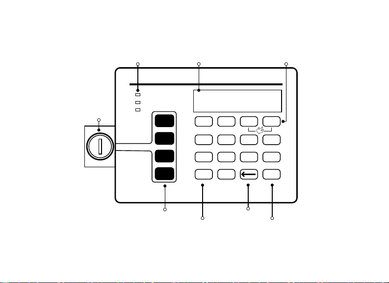
FIRE CONTROL PANEL FEATURES
Select KeysLCD DisplayStatus LEDs
Fire Command Center
POWER
TROUBLE
ENABLE
ALARM
SILENCE
RESET
TEST
DRILL
ABC DEF GHI JKL
1 2 3 4
MNO PQR STU VWX
5 6 7 8
YZ
9 0
COMMAND
Keyswitch
Function Keys
Data Entry Keys
Back Arrow Key
COMMAND Key
Figure 1: Fire Control Panel Features
Page 7

GET TO KNOW THE FIRE COMMAND CENTER
Your system comes equipped with a built-in, easy-to-use Fire Command Center
that allows you to properly operate the system. The Command Center is also
available in a remote version. The keyswitch to the left of the keyboard must be
turned to the “enable” position before you can use the four functions keys. It is
not necessary to use the keyswitch when using a user code to perform operations.
Figure 1 and the descriptions below highlight some features of the Fire Command
Center.
Digital Monitoring Products, Inc. | XR Fire Control Panel User Guide 1
Page 8

The Select Keys
There are four keys under the display called the Select Keys. They allow you to
choose what to do by pressing the Select Key under choices being shown in the
display.
Data Entry Keys
These keys allow you to enter your user code and other information into the
system.
The Back Arrow Key
Use the Back Arrow key to go back through displays while operating your system.
Press the Back Arrow key to back up through the list of User Menu functions or to
make a correction by erasing the last character you entered.
The Command Key
The COMMAND key allows you to advance through the displays or User Menu. You
can also use the COMMAND key to complete a data entry function.
2 XR Fire Control Panel User Guide | Digital Monitoring Products, Inc.
Page 9

Status LEDs
Power LED
This LED remains on steady when both AC and battery input are good. The LED
turns o when AC input is low. The LED flashes when battery input is low.
Trouble LED
This LED turns on when any trouble displays in the status list, such as AC, battery,
phone line, transmit, ground fault, NAC, or any zone trouble. This light is o when
no trouble displays in the status list.
Alarm LED
This LED is on when any alarm currently displays in the status list. This LED is o
when no alarm currently displays in the status list.
Entering Alpha Characters
To enter an alpha character, press the key that has that letter written below it. The
keypad displays the number. Next, press the Select Key that corresponds to the
loca tion of the letter under the key. Pressing a dierent Select Key changes the
letter. Press an other number is pressed to continue.
Digital Monitoring Products, Inc. | XR Fire Control Panel User Guide 3
Page 10

Entering Non-Alpha Characters
To enter a space in an alpha entry, press the 9-digit key followed by the third
Select Key. The three characters on the 9-digit key are Y, Z, and space. You can
also enter the following characters: –(dash), . (period), * (asterisk), and # (pound
sign) using the 0 (zero) key and the four Select Keys from left to right. See the
table below:
KEY NUMBER SELECT KEY 1 SELECT KEY 2 SELECT KEY 3 SELECT KEY 4
1 A B C (
2 D E F )
3 G H I !
4 J K L ?
5 M N O /
6 P Q R &
7 S T U @
8 V W X ,
9 Y Z space _
0 - . * #
4 XR Fire Control Panel User Guide | Digital Monitoring Products, Inc.
Page 11

Using the Keypad
Multi-Lingual Display Option
Your system may be programmed to display the User Menu and Status Display text
in multiple languages. When the COMMAND key is pressed, the option to choose
the language displays.
Keypad Displays Current Programming
Most User Menu options displayed at the keypad show the currently selected
option in the panel memory. These options are either shown as a number, a blank,
or a NO or YES. To change a number press any top row Select Key. The current
option is replaced with a dash. Press the number(s) on the keypad you want to
enter as the new number for that option.
It is not necessary to enter numbers with leading zeros. The panel automatically
right justifies when you press the COMMAND key.
To change an option that requires a NO or YES response, press the top row Select
Key under the response not selected. For example, if the current option is YES
and you want to change it to NO, press the third top row Select Key. The display
changes to NO. Press the COMMAND key to go to the next option.
Digital Monitoring Products, Inc. | XR Fire Control Panel User Guide 5
Page 12

Multiple Displays
For many User Menu options on burglary keypads of combination burglary and
fire systems, such as Access Areas, there are several displays containing lists. For
example, in Access Areas, areas 1 - 32 display on four separate displays. First, areas
1 - 8 display. Press the COMMAND key to display areas 9 through 16. Press the
COMMAND key again to display areas 17 - 25. Press the COMMAND key one more
time to display areas 26 - 32.
Note: Only areas pre-programmed at installation can display.
6 XR Fire Control Panel User Guide | Digital Monitoring Products, Inc.
Page 13

Asterisks in Burglary Area Armed Displays
Asterisks display next to a programming option that is already selected. As shown
in the example, options chosen to display the current programming selection have
an asterisk next to the number. Those that are not selected simply display the
number. In the example, Burglary Areas 3, 8, 9, 15, 19, 23, 25, and 31 are not
selected. In both examples the numbers with asterisks are selected.
To select or deselect a number, enter the number using
the digit keys on the keypad. This is also used when
viewing the panel armed status and other programming
and operational functions. Press the COMMAND key to
display the rest of the device or area numbers.
Digital Monitoring Products, Inc. | XR Fire Control Panel User Guide 7
BURGLARY AREAS
1 2 3 4
5 6 7 8
9 10 11 12
13 14 15 16
17 18 19 20
21 22 23 24
25 26 27 28
29 30 31 32
Page 14

User Options
Allows you to make adjustments to your keypad.
To access User Options, press and hold the Back Arrow and COMMAND keys
for two seconds. The keypad display changes to SET BRIGHTNESS. Press the
COMMAND key to display the next option or the Back Arrow key to exit.
Backlighting Brightness
Sets the keypad LCD and AC LED
backlighting brightness level. At the
SET BRIGHTNESS display, use the
left and right Select Keys to lower or
increase the keypad brightness.
Internal Speaker Tone
Sets the keypad internal speaker tone.
At the SET TONE display, use the top
left and right Select Keys to make the
tone lower or higher.
8 XR Fire Control Panel User Guide | Digital Monitoring Products, Inc.
Volume Level
Sets the keypad internal speaker
volume level for key presses and
prewarn conditions. During alarm,
trouble, and prewarn conditions, the
volume is always at maximum level. At
SET VOLUME LEVEL, use the left and
right Select Keys to lower or raise the
keypad volume.
Model Number
The keypad model number, firmware
version, and date display but can’t be
changed.
Page 15

Four Function Keys
After turning the keyswitch, you can quickly perform vital functions using the four
keys on the left side of the keypad.
SILENCE Key
Pressing the SILENCE key silences the alarm bells.
RESET Key
Pressing the RESET key performs a sensor reset and silence the alarm bells.
TEST Key
Pressing the TEST key performs a system test.
DRILL Key
Pressing the DRILL key displays a prompt SURE? YES NO. Press YES to begin the
fire drill. Press NO to return to the status list.
Digital Monitoring Products, Inc. | XR Fire Control Panel User Guide 9
Page 16

Special Fire Command Center Displays
ALARM
A 24-hour zone or an armed burglary
zone has been tripped.
ALARM NOT SENT
On a Burglary Keypad, the alarm signal
was not sent to the central station
because it was disarmed before the
alarm was sent to the central station.
ALARM CANCELLED
On a Burglary Keypad, an Alarm Cancel
signal was sent to the central station
because it was disarmed after an alarm
was sent to the central station.
10 XR Fire Control Panel User Guide | Digital Monitoring Products, Inc.
SILENCED
An Alarm Silence has been performed
to turn o the notification appliances.
Zone names display.
SUPVSRY (SUPERVISORY)
A Supervisory type zone alarm has
occurred. The zone name displays.
TROUBLE
There is a problem with a protection
device or system component. A
description of the problem displays.
Page 17

ENTER CODE
The system requires you to enter your
user code. User codes can be required
for turning your system on (arming),
turning your system o (disarming),
etc.
As you enter your user code, the
keypad display shows an asterisk (*) in
place of each digit pressed.
TRY AGAIN or INVALID CODE
The user code you have entered is not
in the system. Check the user code and
try again.
INVALID AREA
A user has attempted a door access for
an area they are not assigned.
INVALID TIME
A user code assigned to a specific
schedule is entered outside of the valid
schedule.
ARMED AREA
A user has attempted a door access
to an armed area to which they do not
have authority.
INVALID PROFILE
The profile you entered is not in the
system.
Digital Monitoring Products, Inc. | XR Fire Control Panel User Guide 11
Page 18

FAILED TO EXIT
(ANTI-PASS BACK)
On a Burglary Keypad, anti-passback
requires users to exit (egress) an area
they have previously accessed. If they
fail to exit through the proper card
reader location they are not granted
access on their next attempt. A Failed
to Exit message appears when a user
assigned the anti-passback option
attempts to re-enter an area which they
did not exit properly. The user must
exit the area through the proper door. If
not possible, your system administrator
should select the Forgive option in the
User Codes menu option.
12 XR Fire Control Panel User Guide | Digital Monitoring Products, Inc.
SYSTEM TROUBLE or
SERVICE REQUIRED
There is a problem with one or more
of the components in your system.
Contact our service department.
SYSTEM BUSY
The system is performing another task
of a higher priority. This usually only
takes a few moments.
Page 19
Special Fire Command Center Tones
Fire Alarm Tone
An intermittent sweeping siren that
sounds until the fire alarm is silenced.
Key Press Tone
A short beep each time you press a key
on the keypad and it is acknowledged
by the system.
Prewarn Tone
A continuous pulsed tone that sounds
when you open an entry delay door
on a system that is armed (turned on)
reminding you to disarm the protection.
The tone silences as soon as the first
user code digit key is pressed.
Digital Monitoring Products, Inc. | XR Fire Control Panel User Guide 13
Exit Tone
A continuous pulsing tone that sounds
during the exit countdown just after
arming to remind you to exit the
premise. At ten seconds prior to the
end of the countdown, the rate of
pulsing increases.
Trouble Tone
A steady tone indicating a trouble
condition on your system. Press a
Select Key to silence.
Note: Silencing the trouble tone
by pressing any key only silences
the keypad and does not correct
the condition that originally
caused the trouble.
Page 20

USER MENU
Some features displayed in the User Menu can’t be intereacted with. Only the
features that can be interacted with are listed in this guide. Press the COMMAND
key to skip any displays and prompts not discussed in this User Guide.
User Menu Options
The list below shows the User Menu options in the order they display.
ALARM SILENCE
Silences an alarm bell or siren.
SENSOR RESET
Resets smoke or glassbreak detectors
that have latched due to an alarm
condition.
14 XR Fire Control Panel User Guide | Digital Monitoring Products, Inc.
OUTPUTS ON/OFF
Allows you to turn on or o any of the
outputs described in the System Setup
section of this guide.
ZONE STATUS
Allows you to see if a zone is either
armed, bypassed, in alarm, open, or
shorted.
Page 21

SYSTEM STATUS
Displays the current condition of the
system AC power, backup battery,
optional panel tamper, and keypad
model and version numbers.
SYSTEM TEST
Tests the system siren, communication
to the central station, and backup
battery.
USER PROFILES
Allows you to add, delete, or change
user profiles.
TIME
Allows you to change the Day, Date, or
Time that is currently programmed in
the system.
DISPLAY EVENTS
Allows you to view or print the last
10,000 door accesses or 2,000 system
events that occurred on your system.
SERVICE REQUEST
Allows you to send a message to the
Central Station requesting service on
the alarm system.
USER CODES
Allows you to add, delete, or change
user codes.
Digital Monitoring Products, Inc. | XR Fire Control Panel User Guide 15
FIRE DRILL
Allows you to test the system fire bells.
Page 22

Accessing the User Menu
1. Press the COMMAND key, if the multi-language option is enabled, the
available languages display. Press the top row Select Key under the
language to use for text display.
2. Press the COMMAND key until MENU? NO YES displays.
3. Select YES. The keypad displays ENTER CODE. Enter your user code and
press COMMAND. You can now scroll down through the list of system
features available to you.
16 XR Fire Control Panel User Guide | Digital Monitoring Products, Inc.
Page 23

Alarm Silence
Silences the alarm bells or sirens during an alarm.
Using Alarm Silence does not stop an alarm report from being sent to the central
station and does not reset any alarmed devices.
Note: The keypad tone silences as soon as the first user code digit key is
pressed. You can also silence an alarm by entering your user code and
pressing COMMAND or by presenting your card to a reader while the Status
List displays. If using a proximity card, areas assigned to your card may be
disarmed and door access occurs.
1. Access the User Menu. The keypad displays ALARMSILENCE?.
2. Press any Select Key to silence the bells and exit the User Menu.
Digital Monitoring Products, Inc. | XR Fire Control Panel User Guide 17
Page 24

Sensor Reset
Resets smoke or glassbreak detectors which must be reset before they can detect
any additional alarm conditions. Also clears Fire/Supervisory alarm and trouble
displays.
Make sure all smoke is cleared from around the smoke detector areas before
performing a Sensor Reset to prevent the alarm from occurring again.
1. Access the User Menu. Press COMMAND until SENSOR RESET displays.
2. The keypad displays SENSORSOFF for five seconds followed by
SENSORSON.
3. The keypad automatically exits the User Menu.
18 XR Fire Control Panel User Guide | Digital Monitoring Products, Inc.
Page 25

Lockdown
Locks all Public Doors from the keypad in an emergency situation.
1. Access the User Menu. Press COMMAND until LOCKDOWN? displays.
2. Press any Select Key. The door access relay is activated and all Public
Doors are locked.
3. Press COMMAND to return to the Status List display.
Digital Monitoring Products, Inc. | XR Fire Control Panel User Guide 19
Page 26

Door Lock/Unlock
Locks and unlocks doors from the keypad.
1. Access the User Menu. Press COMMAND until DOOR LOCK/UNLOCK?
displays.
2. Enter the door number and press COMMAND.
-ORPress the fourth Select Key to browse door names. Use the COMMAND key
to scroll through names and press any Select Key when the desired door is
displayed.
3. Press the Back Arrow key to return to the DOOR LOCK/UNLOCK? display.
20 XR Fire Control Panel User Guide | Digital Monitoring Products, Inc.
Page 27

Door Access
Operates an electric door strike from the keypad.
Note: The door strike function is not available on the Model 7872 Graphic
Touchscreen keypad.
Door Access is used to operate the door strike relay that is built into some
keypads. Power for the door strike is connected to the keypad relay and can be
interrupted by using the Door Access function.
Your system may be pre-programmed at installation to transmit a door access
report to the central station.
1. Access the User Menu. Press COMMAND until DOORACCESS? displays.
2. Press any Select Key. The door strike relay turns on momentarily.
3. The keypad returns to the Status List display.
Digital Monitoring Products, Inc. | XR Fire Control Panel User Guide 21
Page 28

Outputs On/O
Allows you to manually turn the system or door access relay outputs ON and OFF.
This function can individually turn your system relay and access door outputs ON
and OFF. Your system may use these outputs to control door access, interior and
exterior lighting, heating, air conditioning, or other appliances.
Outputs can be turned ON or OFF regardless of the output settings in Schedules.
Your system may be programmed to require that your user code profile have
access to areas assigned to the keypad. INVALIDAREA displays when your user
code does not have access to the keypad’s areas and the output does not turn on.
Under certain conditions, some outputs cannot be turned on. If you select a
restricted output, the keypad displays CANNOTTURNON.
1. Access the User Menu. Press COMMAND until OUTPUTSON/OFF? displays.
2. Press any Select Key to display OUTPUTSDOOR.
3. Select the type of output you want to turn ON or OFF by pressing the
Select Key under OUTPUTS or DOOR.
22 XR Fire Control Panel User Guide | Digital Monitoring Products, Inc.
Page 29

4. Enter the output number you want to turn ON or OFF. The output number
displays. The range for outputs is 1-6, 500-999. The range for the door is
1-16.
5. With the output number displays, press the Select Key under ON or OFF.
The remains in that chosen state until you change it. The keypad displays
the output or door name followed by either ON or OFF for four seconds to
provide visual verification of the action. Press the COMMAND key to end
the four-second display.
6. The system automatically returns to the output or door prompt to allow
you to select a new output to turn ON or OFF. Refer back to step 4.
Favorite
Allows you to activate a Favorite.
1. Access the User Menu. Press COMMAND until FAVORITE displays.
2. Enter a Favorite number from 1-20. Pressing COMMAND activates the
Favorite.
Digital Monitoring Products, Inc. | XR Fire Control Panel User Guide 23
Page 30

Zone Status
Zone Status can be used to give you a list of zones by category or display the
current status of an individual zone number.
1. Access the User Menu. Press COMMAND until ZONE STATUS? displays.
2. Press any Select Key to display ARMBYPSALRNBR.
ARM, BYPS, and ALR provide a list of zones with that status to scroll
through using COMMAND.
NBR allows you to select a specific zone to acquire its status.
• Select ARM for a list of zones that are currently armed.
• Select BYPS for a list of zones that are currently bypassed.
• Select ALR for a list of zones that have gone into alarm during the
current or previous armed period.
24 XR Fire Control Panel User Guide | Digital Monitoring Products, Inc.
Page 31

• Select NBR and ZONE NO displays. Enter the zone number you want
to check and press COMMAND. The zone number and name display
followed by the zone status. The following is a list of the zone status
displays:
OK AY The zone is in a normal condition
BYPA S The zone is bypassed
BAD The zone is in a bad or faulted condition
After displaying the zone status, ZONE NO returns for you to enter
another zone number.
Digital Monitoring Products, Inc. | XR Fire Control Panel User Guide 25
Page 32

System Status
System Status displays the internal system hardware current condition.
System Status shows the panel condition of AC power, battery power, and optional
panel tamper. When System Status is selected, each monitor displays followed by
OKAY or TRBL (Trouble) to indicate the current condition.
1. Access the User Menu. Press COMMAND until SYSTEMSTATUS? displays.
2. Press any Select Key. The display starts listing each system monitor and
status. For example: ACPOWER-OKAY. Below are the System Monitor
displays:
KEYPAD DISPLAY WHAT IT MONITORS
AC POWER AC power
BATTERY Battery power
TAMPER Panel box tamper
These are followed by either O KAY or TRBL (trouble). If TRBL displays, call
the service department for assistance.
3. The system then displays its firmware version, the panel model, and then
exits the User Menu.
26 XR Fire Control Panel User Guide | Digital Monitoring Products, Inc.
Page 33

System Test
System Test is used to test the battery, alarm bell or siren, and communi cation to a
central station. The System Test function begins automatically as soon as you select it.
Using the System Test Function
1. Access the User Menu. Press COMMAND until SYSTEM TEST? displays.
2. The keypad displays SYSTEMPANICS. Press the Select Key below SYSTEM.
3. The System Test begins automatically and the keypad displays the following
messages in this order:
a. BELL SOUNDING during a two second bell test
b. KEYPAD SOUNDING all keypads assigned to the same area sound
their alarm tone for two (2) seconds during the keypad sounder test
c. BATTERY-OKAY or BATTERY-TRBL to indicate the battery condition
d. *TRANSMIT TEST and ATTEMPT NO: 1 during the transmit test
e. TRANSMIT OKAY or TRANSMIT FAILED to show the results of the
transmit test
f. TEST END to indicate the System Test is complete.
g. You can press the Back Arrow key to end the transmit test.
* The transmit test does not occur on local systems.
Digital Monitoring Products, Inc. | XR Fire Control Panel User Guide 27
Page 34

Using the Panic Zone Test (XR550DNFC with Network)
1. Access the User Menu. Press COMMAND until SYSTEM TEST? displays.
2. Press any Select Key. The keypad displays SYSTEMPANICS.
3. Press the Select Key below PANICS.
4. The Panic Zone Test begins automatically and the keypad displays
TRIPS:END.
5. During the test, trip each panic zone (or button) on the system by pressing
and holding the panic for 1 to 2 seconds.
Note: You do not have to hold the panic for 2 seconds in normal
mode. You are only required to hold the panic during the Panic Zone
Test because the zone takes additional time to report when the system
is in test mode.
Each time you trip a panic zone, the display number increments and the
keypad buzzer sounds for two seconds.
The number of panic zones tripped constantly displays until the test ends
or no panic zone activity has occurred for 20 minutes.
6. Press the Select Key below END to stop the Panic Zone Test.
28 XR Fire Control Panel User Guide | Digital Monitoring Products, Inc.
Page 35

7. When PANICTESTOKAY displays, the Panic Zone Test is completed and all
zones tested OK.
8. When the Panic Zone Test ends and a zone failed (did not trip) during
the test, the keypad displays the zone name and number and the buzzer
sounds for one second. Press the COMMAND key to display the next failed
zone.
Note: During the Panic Zone Test, any zones that fail are not sent to
the receiver unless pre-programmed at installation to be sent.
Digital Monitoring Products, Inc. | XR Fire Control Panel User Guide 29
Page 36

User Profiles
Change User Profiles, that define the authority of each user code in the system.
Several characteristics define the authority of each User Profile within the system.
Always make sure that at least one administrator in your system has a profile with
all authorities and all areas.
Profile Number
Each profile may be assigned a unique
number from 1 to 99.
Profile Name
Each profile may be assigned a
16-character name. The Profile Number
is the default name.
30 XR Fire Control Panel User Guide | Digital Monitoring Products, Inc.
Arm or Disarm Areas
Each profile may be assigned specific
areas of the system for arming and
disarming. When profiles 1 to 98 are
created, NO areas are assigned by
default. The default for profile 99 is ALL
areas assigned. Profile 99 is predefined
in the system by the factory.
Page 37

Access Areas
Each profile may be assigned door
access area assignments. Default for
profile 1 to 98 is NO areas assigned.
Default for profile 99 is ALL areas
assigned. Profile 99 is predefined at the
factory.
Output Group Assignment
Each profile may be assigned an
output group number from 1 to 10.
Default for profile 1 to 98 is NO output
group assigned. Default for profile 99
is output group 10. Your system may
by programmed to turn on an output
group at certain keypads when door
access occurs.
Digital Monitoring Products, Inc. | XR Fire Control Panel User Guide 31
User Menu Assignments
Each user profile may have any of the
menus assigned to it as shown in the
User Profile Record below. The User
Profile Record lists the user menu
profile assignments and the system
functions users are allowed to access
based on the profile numbers assigned
to their codes.
Page 38

User Profiles Reference
MENU DISPLAY PRIVILEGE
ARM NO YES Arm
DIS NO YES Disarm
ALM SLNC NO YES Alarm Silence
SNSR RST NO YES Sensor Reset
LOCKDOWN NO YES Lockdown
DOOR LOCK/
UNLOCK
DOOR ACS NO YES Door Access
ARM AREA NO YES Armed Areas
OUTPUTS NO YES Outputs ON/OFF
FAVORITES F01 - F20 Favorites
ZN STAT S NO YES Zone Status
BYPAS ZN NO YES Bypass Zones
ZONE MON NO YES Zone Monitor
SYS S TAT NO YES System Status
SYS TEST NO YES System Test
NO YES Door Lock/Unlock
MENU DISPLAY PRIVILEGE
PROFILES NO YES User Profiles
USR CODE NO YES User Codes
SCHEDULS NO YES Schedules
TIME NO YES Time
DIS EVNT NO YES Display Events
SERV REQ NO YES Service Request
FIRE DRILL NO YES Fire Drill
EXTEND NO YES Extend Schedules
TEMP CODE NO YES
ANTI PASS NO YES Anti-Passback
ACCESS
SCHEDULES
RE ARM DLY 0 – 720 Re-Arm Delay
SEC
LANGUAGE
Sch. 1-99
NO YES Preferred Language
Temporary User
Code
Allow: Shift/Time
Access
Changing User Profiles
1. Access the User Menu. Press COMMAND until USER PROFILES? displays.
2. Press any Select Key. The keypad displays ADDDELCHG.
3. Press the far right Select Key, under CHG.
32 XR Fire Control Panel User Guide | Digital Monitoring Products, Inc.
Page 39

4. At the PROFILE NO option, enter a profile number and press COMMAND.
The display changes to PROFILENAME.
5. Press any Select Key to display -.
6. Enter a profile name of up to 16 characters. The default Profile Name uses
the Profile Number.
7. Enter the Profile Name and press COMMAND.
8. At the ARM/DIS AREAS option, enter the area numbers (1-32) for arming
and disarming assigned to this profile.
9. At ACCESSAREAS, enter the area numbers (1-32) assignment to allow
door access for this profile. Press COMMAND.
10. At OUTPUTGROUP, Enter the number (1 through 20) for the Output Group
assigned to this profile. Press COMMAND.
11. The keypad displays each of the menus as shown in the Profile References
Table. Enable or disable the menu function for this profile number. Select
YES or NO and press COMMAND to advance to the next menu selection.
12. After all User Profile menu assignments are selected, the keypad displays
the PROFILE CHNGD message for 4 seconds, indicating the profile is
changed.
Digital Monitoring Products, Inc. | XR Fire Control Panel User Guide 33
Page 40

TEMP CODE
When you select YES for this menu
option, and this profile is assigned to
a user code (see next section), the
keypad displays TEMP EXPIRE DATE.
Enter the ending date for the profile to
expire. Default is seven days from today.
The system deletes Temp users at 12:00
AM on the last date.
ANTI PASS NO
Anti-passback requires that you
properly exit (egress) an area
previously accessed. When you fail to
exit through the proper location you
cannot access it until you properly exit.
Default is NO.
34 XR Fire Control Panel User Guide | Digital Monitoring Products, Inc.
ACCESS SCHEDULES
This option allows you to assign
two Schedules to a profile for door
access. When the keypad displays
FIRSTACCESSSCHEDULE press
COMMAND to browse available
Schedules. Enter the Schedule
number and press COMMAND.
When the keypad displays
SECONDACCESSSCHEDULE repeat
the same process for the third through
eighth access schedule and press
COMMAND to return to the User Menu.
RE ARM DELAY
This option allows the entry of 0 to 720
minutes to be used to delay automatic
rearming when the user disarms an
area outside of schedule. If zero is
selected, the rearming occurs based on
permanent programming in the panel.
Page 41

RE ARM DELAY is also used to delay
a late to close message to the central
station when the panel does not use
automatic arming.
If the user has Extend Schedule
authority, 2HR4HR6HR8HR displays
at disarming. If the user does not make
a choice, the REARMDELAY is used to
extend the schedule.
For example, an exit door near the
trash is scheduled to be armed at all
times. When the custodian needs to
remove trash, program 10 minutes
for the activity. Or, an overhead door
only requires access when a delivery is
made. Program up to 250 minutes to
allow the loading dock supervisor to
load or unload a semi-truck.
Digital Monitoring Products, Inc. | XR Fire Control Panel User Guide 35
Page 42

User Codes
This option allows you to add, delete, or change a user code. You may also assign
specific User Profiles to individual users.
User Number
Every user is numbered 1 - 9999. This
number identifies the user to the
system and is transmitted to the central
station when the user arms or disarms
areas.
User Code
Each user also has a 3- to 6-digit code,
to enter into the LCD keypad when
arming or disarming the system.
Note: A User Code cannot begin
with zero, and 3-digit codes
cannot begin with 98.
36 XR Fire Control Panel User Guide | Digital Monitoring Products, Inc.
User Names
Each code may also be programmed
with the user name. You may enter up
to 16 characters for the name.
User Profile
The user is also assigned a Profile (1 to
99) by the administrator of the system.
The profile number determines the areas
and functions the user can access.
Note: Your system must have at
least one user with user code
authority in order to add or
delete user codes. Do not delete
all users with user code authority
from your system.
Page 43

Adding User Codes
1. Access the USER CODES? display. Press any Select Key. The keypad
displays ADD DEL CHG BAT.
2. Press the Select Key under ADD or BAT (Batch) to add a new user code.
3. At the USER NUMBER prompt, enter a user number and press COMMAND.
The display changes to USERCODE.
Note: Do not program a code for user number 1 unless you intend to
use the Ambush function, see Ambush Codes.
4. Enter a user code of 3 to 6 digits and press COMMAND. The user enters
this number to arm, disarm, etc. After entering the code the keypad
displays USER NUMBER ### as the user name.
5. A 16-character name may be entered to identify the user. Press any top row
key to clear the current name. Enter the new name and press COMMAND.
6. The display changes to PROFILENO. Select the profile number to assign a
set of authorized functions to the user code.
7. At the PROFILE NO display, enter a profile number from 1 to 99, and press
COMMAND. The displays shows USER#ADDED.
Digital Monitoring Products, Inc. | XR Fire Control Panel User Guide 37
Page 44

Deleting User Codes
To delete a user code, you must have a user code with a profile that has user code
authority.
1. Access the USER CODES? display. Press any Select Key. The keypad
displays ADD DEL CHG BAT.
2. Press the second Select Key, under DEL, to delete a user code from the
system. To delete a user code, you must have a user code with a profile that
has user code authority.
Note: Be careful not to delete all users with user code authority from
your system. Also, the user code used to enter the user menu to
delete codes cannot be deleted. In other words, you can not delete
yourself.
3. At the USER NUMBER prompt, enter the user number you want to delete
and press COMMAND. The display changes to USER # DELETED.
4. The display then changes back to USER NUMBER allowing you to delete
another user.
38 XR Fire Control Panel User Guide | Digital Monitoring Products, Inc.
Page 45

Changing User Codes
1. Access the USER CODES? display. Press any Select Key. The keypad
displays ADD DEL CHG BAT.
2. Press the third Select Key, under CHG, to change a user code.
3. At the USER NUMBER prompt, enter the user number to change and press
COMMAND.
4. The display changes to CODENO:******. Press a Select Key and enter
the new user code. Press COMMAND.
Changing a user code does not change the user number.
5. The display then shows the current user name. Press any top row key to
clear. See Entering User Names in Working with Browsers to enter a new
name.
6. The display changes to PROFILENO. Select the profile number to assign a
set of authorized functions to the user code.
7. After entering the profile number, the keypad displays USER # CHANGED
for 5 seconds followed by USER NUMBER. This display allows you to
change another user code.
Digital Monitoring Products, Inc. | XR Fire Control Panel User Guide 39
Page 46

Extend Closing
Extending schedules (EXT) allows the Closing Check operation to delay until the
new closing time expires. This allows the current schedule to ignore its closing time
and not send a LATE TO CLOSE message to the central station. This function is
designed to allow workers to stay later and does not extend door access authority.
The extended schedule erases when it expires.
1. Access the User Menu. Press the COMMAND until SCHEDULES displays.
2. Press any top row Select Key to view OUTDOORHOLEXT. Select EXT to
program Extended Schedules.
3. If Area Schedules are set to YES in Area Information you are prompted to
enter the Area for which you wish to extend the closing time. Press any
Select Key to browse Area names and press COMMAND at the chosen
Area.
4. The keypad displays AM PM. Enter a time to extend the current Closing
Check open period. Press COMMAND to exit the menu.
Note: If the system is not armed by the scheduled closing time, a
Late to Close report is sent to the central station. If the schedule is
extended, a Schedule Change report is sent to the central station.
40 XR Fire Control Panel User Guide | Digital Monitoring Products, Inc.
Page 47

Setting Schedules
1. Access the User Menu.
2. The keypad displays TIMESAREASDOOR. Press COMMAND to display
OUTPUTHOLIDAYS. Select the function you want to program.
Times
The keypad displays ADD DEL CHG.
Adding a Schedule
Select ADD to enter a new schedule number.
1. Enter the Schedule number 01-99 that you want to add. Press the
COMMAND key to accept your Selection. You are then given the option to
enter a Schedule name. Press CMD to proceed.
2. The keypad displays SUNMONTUEWED. Press the COMMAND key to
display THUFRISATHOL. Select the day you want the schedule to begin.
If you select HOL, go to Setting Holiday ABC Schedules for additional
instructions.
Digital Monitoring Products, Inc. | XR Fire Control Panel User Guide 41
Page 48

Note: After selecting the day of the week or holiday for the schedule
to begin, the keypad displays any currently programmed Begin and
End times previously set for that day. This feature allows you to
review programmed schedules at any time.
3. If Begin and End times already exist, the keypad then displays
DELETEKEEP. Select DELETE to enter new times.
4. The keypad then displays BEGIN TIME? followed by the display
MON –:AMPM. Enter the new opening time and select AM or PM. Enter
all schedule times using a 12 hour clock. For example, to enter 6 AM you
would enter a 0 + 6 + 0 + 0 and select AM. For 11 PM you would enter a 1 +
1 + 0 + 0 and select PM.
The keypad then displays END TIME? followed by the display MON – : AM
PM. Enter the new closing time and select AM or PM. Select whichever day
displays, for example, MON allows you to scroll through the days of the
week and create a schedule window that spans multiple days.
Note: You must enter a Begin and End time or the system will not
recognize the schedule.
42 XR Fire Control Panel User Guide | Digital Monitoring Products, Inc.
Page 49

5. Now that the new shcedule is programmed into your system, the keypad
goes back to the SUN MON TUE WED display. Press the Back Arrow key to
enter another schedule.
6. To clear a schedule press DELETE and then AM when the opening time is
requested. Press the Back Arrow key to exit the User Menu.
Delete a Schedule
Select DEL to delete a schedule number.
1. Enter the Schedule number 01-99 that you want to delete.
2. The keypad displays DELETESCHEDULESURE?YESNO. Select YES to
delete the schedule.
3. The keypad displays SCHEDULENO:-DELETED and the keypad prompts
you for the next schedule number to be deleted.
Digital Monitoring Products, Inc. | XR Fire Control Panel User Guide 43
Page 50

Change a Schedule
Select CHG to edit an existing schedule.
1. Enter the schedule number 01-99 that you want to change.
2. The keypad displays ENTERSCHEDULE and the schedule name. To edit the
name press any Select Key to make changes. Press CMD to proceed.
3. The keypad displays SELECTWEEKDAY and SUNMONTUEWED. Press
the COMMAND key to display THU FRI SAT HOL.
4. Enter the Begin and End times for each day of the schedule. Refer to
Adding a Schedule for more information.
5. The keypad goes back to the SUNMONTUEWED display. Press the Back
Arrow key to enter another schedule.
44 XR Fire Control Panel User Guide | Digital Monitoring Products, Inc.
Page 51

Setting Area, Output, and Door Schedules
The Schedules function allows you to assign up to 8 dierent schedule numbers to
each area, output, and door access relay connected to your system. The schedule
number allows the opening and closing times for the area and on/o times for
outputs and door access relays
1. Access the User Menu.
2. Press COMMAND until SCHEDULES? displays. Press any Select Key.
3. At TIMESAREASDOOR, press the COMMAND key and the display changes
to OUTPUT HOLIDAYS. Select AREAS, DOOR, or OUTPUT.
4. At ENTER THE AREA/OUTPUT/DOOR NUMBER, enter the area, output, or
door number you want to assign a schedule. Press the COMMAND key.
5. At SCHEDULENO, press any Select Key and enter the schedule
number (01 to 99). Press the COMMAND key. The keypad returns to
the TIMESAREASDOOR display allowing you to enter additional
programming.
Digital Monitoring Products, Inc. | XR Fire Control Panel User Guide 45
Page 52

Setting Holiday ABC Schedules
Three Holiday Schedules are available. This allows an output, area, or door to have
three dierent schedules for holidays. For example, Holiday Schedule A for those
holidays when the building stays closed, Holiday Schedule B for a day that only
opens for a morning, etc. Also, Holiday Schedules can be used to cross multiple
days. These schedules become active and supersede the current day’s schedule
when a Holiday Date occurs. See Setting Holiday Dates (HOL).
1. Access the User Menu. Press COMMAND until SCHEDULES? displays. Press
any Select Key.
2. At TIMESAREASDOOR, display, press the COMMAND key until the display
changes to OUTPUT HOLIDAYS. Press COMMAND once more and the
display changes to FAVORITES.
3. Select HOLIDAY to program holiday schedules.
4. The keypad displays HOL: A B C. Select A to set the first of three holiday
schedules.
46 XR Fire Control Panel User Guide | Digital Monitoring Products, Inc.
Page 53

5. The keypad displays A - : AM PM.
Note: After selecting the schedule, the keypad displays any current
times previously set for that holiday. This feature allows you to review
the programmed times.
6. If times display, the keypad then displays DELETE KEEP. Select DELETE to
enter new times.
7. The keypad then displays BEGINTIME? This is followed by the display AM
PM.
Enter a new time and select AM or PM.
The display changes to END TIME?. This is followed by the display AMPM.
Enter a new time. Enter all schedule times using a 12 hour clock. For
example, to enter 6 AM you would enter 0 + 6 + 0 + 0 select AM. For 11 PM
you would enter 1 + 1 + 0 + 0 and select PM.
8. The keypad returns to HOL:ABC allowing you to enter A, B, and/or C
holiday schedule for the same Output or Door. Go back to step 3 to add
additional holiday schedules.
Digital Monitoring Products, Inc. | XR Fire Control Panel User Guide 47
Page 54

Setting Holiday Dates
Setting Holiday Dates provides the system with dates in the year when the normal
opening and closing schedules are not used and superseded by one of the Holiday
Schedules A or B or C. When the panel determines that it is a holiday, the Holiday
Schedule supersedes the current schedule for that day. Up to fourty dierent
holiday dates can be entered.
1. Access the User Menu. Press COMMAND until SCHEDULES? displays. Press
any Select Key.
2. At TIMESAREASDOOR, display, press the COMMAND key once more.
The display changes to OUTPUTHOLIDAYFAVORITES. Select Holiday to
program Holiday dates.
3. At HOL: xx mm/dd A. You can now enter the month and day for the first
holiday. Select A to change to HOL B. Pressing again changes to HOL C.
Example: July 4th would be entered by pressing the 0704 keys. The keypad
displays HOL:1 07/04 B.
48 XR Fire Control Panel User Guide | Digital Monitoring Products, Inc.
Page 55

4. To step to the next holiday number, press COMMAND. To clear a holiday
press any top row Select Key when the appropriate holiday number
displays. Press the Back Arrow key when HOL: 1 or the COMMAND key
when HOL: 40 displays to exit the menu.
Note: The Holiday Dates entered indicate the days of the year when
HOL schedules are used. For information on setting holiday schedules
for Area, Output, and Door, see Setting Holiday ABC Schedules.
Setting the Date and Time
Allows you to change the current date and time displayed on the LCD keypad and
used by the system.
1. Access the User Menu. Press COMMAND until TIME? displays. Press any
Select Key.
2. The keypad displays the current day and time. Press the COMMAND key.
The keypad displays the current date. Press the CMD key to make any
changes.
3. The keypad displays TIMEDAYDATE.
Digital Monitoring Products, Inc. | XR Fire Control Panel User Guide 49
Page 56

4. Press the Select Key under TIME to change the time. The keypad displays
AM PM. Enter the current time and select AM or PM. The display changes
back to TIMEDAYDATE.
5. Press the Select Key under DAY to change the day of week. The keypad
displays SUNMONTUEWED. Press the COMMAND key to display
THUFRISAT. Press the Select Key under the correct day. Use the Back
Arrow key to toggle between the dierent day of the week displays.
6. Press the Select Key under DAT E to change the date. The keypad displays
MONTH Enter up to 2 digits for the month. Press CMD.
DAY Enter up to 2 digits for the day. Press CMD.
YEAR Enter up to 2 digits for the year. Press CMD.
The display returns to the TIME DAY DATE display.
Press the Back Arrow key to exit the User Menu.
50 XR Fire Control Panel User Guide | Digital Monitoring Products, Inc.
Page 57

Ambush Codes
Your system may be programmed to allow user number 1 to be used as an
Ambush code. This Ambush code functions identically to a standard code with
the exception that it sends a silent alarm to the central station. This silent alarm
alerts the operator to a duress situation at the premises and prompts immediate
notification of authorities.
Refer to the System Setup section of this guide to see if your system is
programmed for Ambush. If so, do not program a code for user number 1 unless
you intend to use the Ambush function.
Digital Monitoring Products, Inc. | XR Fire Control Panel User Guide 51
Page 58

Display Events
Allows you to review up to 12,000 past door access and system events. Examples
of these events include:
• Zone Activity: zone alarms, troubles, and restorals.
• User Code: adding, deleting, and changing user codes.
• Supervisory: problems with system hardware components.
• System Monitor: problems with AC Power, Battery, phone line, or tamper
problems.
The system memory holds a maximum of 12,000 past events for 45 days. Any
event older than 45 days automatically clears from the system memory. Also, once
the full 12,000 events are stored, any new event causes the oldest event to be
cleared.
About the Display Events Section
While in the Display Events function, use the COMMAND and Back Arrow keys to
navigate through the list of events.To view more information about each display,
press the Select Key as directed in the explanations.
52 XR Fire Control Panel User Guide | Digital Monitoring Products, Inc.
Page 59

Using the Display Events
1. Access the User Menu. Press the COMMAND key until DISPLAY EVENTS?
displays. Press any Select Key.
The keypad displays FRST LST PRT SRT.
a. Select FRST (first) to view the oldest to newest events. Then use the
COMMAND key to scroll up through the events. Select LST (last) to
view the newest to oldest events. Then use the Back Arrow key to scroll
down through the events.
b. Select LST (last) to view the newest to oldest events. Then use the Back
Arrow key to scroll down through the events.
c. Select SRT to sort through the Display Events log and collect
information specific to a user or system event.
d. Select PRT to print the complete Display Events log.
2. To use the Sort feature, press the Select Key under SRT. The keypad
displays FRSTDATE:8/21. Press any Select Key and enter a 4-digit
beginning date for the sort. Press COMMAND.
3. The keypad displays LASTDATE:10/17. Press any Select Key and enter a
4-digit ending date for the sort. Press COMMAND.
Digital Monitoring Products, Inc. | XR Fire Control Panel User Guide 53
Page 60

4. At USERNUMBER, to sort events for a particular user, enter their user
number or press COMMAND to sort for all users. To search for a user, press
any Select Key then use the COMMAND and Back Arrow keys to browse
through the user names in the system. When the user you want displays,
press any Select Key then press COMMAND.
5. The keypad displays five event types that you can include in the sort. Press
the fourth Select Key to display YES as the event type name displays on the
keypad. Press COMMAND. The following are the five sort event types:
• ACCESSES: Door accesses granted
• DOOR NUMBER: Leave blank for all doors
Note: If you select YES for access then only Door Access
Granted Events are included in the sort.
• ZONE EVENTS: Zone alarms, troubles, and restorals
• USER EVENTS: Adding, deleting, and changing user codes
• SUPERVISORY: System hardware problems and door access denied
events
6. After the last event type displays, the keypad again displays
FRSTLSTPRTSRT. You can now view or print the sorted Display Events or
press SRT to define a new sort.
54 XR Fire Control Panel User Guide | Digital Monitoring Products, Inc.
Page 61

Service Request
Your user code profile may be programmed for Service Request. This allows you
to press any top row Select key when SERVICE REQUEST? displays and have the
system send a “Request for Service” message to the central station. The REQUEST
MADE display confirms your request was sent.
Digital Monitoring Products, Inc. | XR Fire Control Panel User Guide 55
Page 62

Fire Drill
Fire Drill is used to test the fire bells or fire horns in your system. The Fire Drill
test turns your system bell circuit on, but does not send a message to the central
station.
Starting a Fire Drill test
1. Access the User Menu. Press COMMAND until FIRE DRILL? displays. Press
any Select Key.
2. The keypad displays SURE? YES NO.
3. Press the Select Key under YES to start the Fire Drill test.
Ending a Fire Drill test
1. Enter your code at the keypad and press COMMAND to end the Fire Drill.
2. The Fire Drill test automatically ends with ALARM SILENCE or the
programmed Bell Cuto time.
56 XR Fire Control Panel User Guide | Digital Monitoring Products, Inc.
Page 63

COMMON KEYPAD DISPLAYS
Listed in the following table are several keypad messages you may see on the
display. Follow the instructions in the Possible Solutions column to correct the
problem. In many case, you need to call a service person to correct the problem.
Displays that are not discussed here mean that your service representative should
be called.
Digital Monitoring Products, Inc. | XR Fire Control Panel User Guide 57
Page 64

MESSAGE: MEANING: POSSIBLE SOLUTIONS:
INVALID AREA The user has attemped a door access to
INVALID CODE The user code you entered is not
INVALID PROFILE A user has attempted a function that is
INVALID TIME A user code assigned to a specific
ENTER 2ND CODE The area you are attempting to disarm or
CLOSING TIME! The schedule has expired and in a short
LATE TO CLOSE The system was no armed at its
FAILED TO EXIT A user assigned the anti-passback option
58 XR Fire Control Panel User Guide | Digital Monitoring Products, Inc.
an area they are not assigned.
recognized by the assigned profile.
outside of the assigned profile.
schedule was entered outside of the
valid schedule.
access is a Two Man Area.
time the area will automatically arm.
scheduled closing time.
has attempted to re-enter an area from
which they did not exit properly.
Change the user access areas if access to
the area is needed. If access is needed,
the user cannot enter the area.
Check the user code and try again.
Check the user profile settings.
See Schedules and User Codes.
Check the system clock.
A second and dierent user code must
be entered.
Users still on the premise should arm
the system or extend the schedule to a
later time.
Users still on the premise should arm
the system or extend the schedule to a
later time.
The user must exit the area through the
proper door. If not possible, your system
administrator should select the Forgive
option in the User Codes menu.
Page 65

Page 66

Page 67

Information furnished is believed to be accurate and reliable.
This information is subject to change without notice.
Page 68

DESIGNED, ENGINEERED, AND MANUFACTURED IN SPRINGFIELD, MISSOURI USING U.S. AND GLOBAL COMPONENTS.
INTRUSION • FIRE • ACCESS • NETWORKS
DMP.COM | LT-1298 | 21153
 Loading...