


PROGRAMMING GUIDE
XR150/XR550 INTERNATIONAL
SERIES CONTROL PANEL

MODEL XR150INT/XR550INT SERIES
CONTROL PANEL PROGRAMMING GUIDE
Contains programming Instructions for use with the
Model XR150INT/XR550INT Series Control Panels
When using the XR150INT/XR550INT Series panel for any listing organization’s approved methods, refer to this manual and
the XR150INT/XR550INT Series Installation Guide (LT-1233INT). These documents outline the installation and programming
requirements of all applications for which the XR150INT/XR550INT Series is approved.
FCC NOTICE
This equipment generates and uses radio frequency energy and, if not installed and used properly in strict accordance with the
manufacturer’s instructions, may cause interference with radio and television reception. It has been type tested and found to
comply with the limits for a Class A computing device in accordance with the specication in Subpart J of Part 15 of FCC Rules,
which are designed to provide reasonable protection against such interference in a residential installation. If this equipment does
cause interference to radio or television reception, which can be determined by turning the equipment o and on, the installer is
encouraged to try to correct the interference by one or more of the following measures:
Reorient the receiving antenna
Relocate the computer with respect to the receiver
Move the computer away from the receiver
Plug the computer into a dierent outlet so that computer and receiver are on dierent branch circuits
If necessary, the installer should consult the dealer or an experienced radio/television technician for additional suggestions. The
installer may nd the following booklet, prepared by the Federal Communications Commission, helpful:
“How to identify and Resolve Radio-TV Interference Problems.”
This booklet is available from the U.S. Government Printing Oce, Washington D.C. 20402
Stock No. 004-000-00345-4
© 2021 Digital Monitoring Products, Inc.
Information furnished by DMP is believed to be accurate and reliable. This information is subject to change without notice.
Digital Monitoring Products XR150/XR550 International Series Programming Guide
b

TABLE OF CONTENTS
Introduction ....................................................................................................1
1.1 Before You Begin ........................................................................................................... 1
1.2 Getting Started ..............................................................................................................1
1.3 Programmer Operation ...................................................................................................2
1.4 Programmer Lockout Codes ............................................................................................ 2
1.5 Reset Timeout ............................................................................................................... 2
1.6 Power Up ...................................................................................................................... 3
1.7 Keypads ........................................................................................................................ 3
1.8 Special Keys .................................................................................................................. 3
1.9 Entering Characters Using the Number Pad .....................................................................4
1.10 Keypad Displays Current Programming ............................................................................ 4
1.11 Multiple Displays ............................................................................................................5
1.12 Asterisks in Programming ............................................................................................... 5
1.13 Compliance Instructions ................................................................................................. 5
Initialization .................................................................................................... 6
2.1 Initialization ..................................................................................................................6
2.2 Clear All Memory ........................................................................................................... 6
2.3 Clear All Codes .............................................................................................................. 6
2.4 Clear All Schedules ........................................................................................................ 6
2.5 Clear Display Events Memory ..........................................................................................6
2.6 Clear Zone Information ..................................................................................................6
2.7 Clear Area Information ...................................................................................................6
2.8 Clear Output Information ...............................................................................................6
2.9 Clear Communication and Remote Options ...................................................................... 6
2.10 Clear Wi-Fi .................................................................................................................... 6
2.11 Set to Factory Defaults ................................................................................................... 6
Communication ...............................................................................................7
3.1 Communication .............................................................................................................7
3.2 Account Number ............................................................................................................7
3.3 Transmit Delay .............................................................................................................. 7
3.4 Communication Path ...................................................................................................... 7
3.5 Communication Type ..................................................................................................... 7
3.6 Path Type............................................................................................................ ..........7
3.7 Test Report ................................................................................................................... 7
3.8 Test Frequency .............................................................................................................. 7
3.9 Test Day ....................................................................................................................... 8
3.10 Test Time ...................................................................................................................... 8
3.11 Check In ....................................................................................................................... 8
3.12 Fail Time ....................................................................................................................... 8
3.13 Encryption (XR550INT with Encryption only) ................................................................... 8
3.14 IPV6 Address ................................................................................................................8
3.15 Receiver IP ...................................................................................................................8
3.16 Receiver Port ................................................................................................................. 8
3.17 First Telephone Number ................................................................................................. 8
3.18 Second Telephone Number ............................................................................................. 9
3.19 Advanced Programming .................................................................................................9
3.20 APN .............................................................................................................................. 9
3.21 Fail Test Hours .............................................................................................................. 9
3.22 Protocol ........................................................................................................................ 9
3.23 Retry Seconds ............................................................................................................... 9
3.24 Substitution Code .......................................................................................................... 9
3.25 893A ............................................................................................................................9
3.26 Alarm Switch ................................................................................................................. 9
3.27 Duplicate Alarms ......................................................................................................... 10
3.28 Alarm Reports ............................................................................................................. 10
3.29 Supervisory/Trouble Reports ......................................................................................... 10
3.30 Opening/Closing and User Reports ................................................................................ 10
3.31 Door Access Report ..................................................................................................... 10
XR150/XR550 International Series Programming Guide Digital Monitoring Products
i

TABLE OF CONTENTS
3.32 Panic Test (Network only)............................................................................................. 10
3.33 Send Communication Trouble ....................................................................................... 10
3.34 Send Path Information ................................................................................................. 10
Network Options ...........................................................................................11
4.1 Network Options.......................................................................................................... 11
4.2 WiFi Setup .................................................................................................................. 11
4.2.1 WPS ........................................................................................................................... 11
4.2.2 List ............................................................................................................................. 11
4.2.3 Manual ....................................................................................................................... 11
4.2.4 Test ............................................................................................................................ 12
4.3 Wireless Security Type ................................................................................................. 12
4.4 Wireless Network Key .................................................................................................. 12
4.5 IPV6 ................................................................................................................... 12
4.6 DHCP .......................................................................................................................... 12
4.7 Local IP Address ......................................................................................................... 12
4.8 Gateway Address ......................................................................................................... 12
4.9 Subnet Mask ............................................................................................................... 12
4.10 DNS Server ................................................................................................................. 12
4.11 734N Listen Port. ......................................................................................................... 12
4.12 734N Passphrase ......................................................................................................... 12
Device Setup .................................................................................................13
5.1 Device Setup ............................................................................................................... 13
5.2 Custom Card Denitions ............................................................................................... 13
5.2.1 Site Code Position ........................................................................................................ 13
5.2.2 Site Code Length ......................................................................................................... 13
5.2.3 User Code Position ....................................................................................................... 13
5.2.4 User Code Length ........................................................................................................ 13
5.2.5 Require Site Code ........................................................................................................ 13
5.2.6 Site Code Display ..........................................................................................................13
5.2.7 Number of User Code Digits ......................................................................................... 13
5.3 Device Number ............................................................................................................ 14
5.4 Device Name ............................................................................................................... 15
5.5 Device Type ................................................................................................................ 15
5.6 Device Communication Type ......................................................................................... 15
5.7 Serial Number ............................................................................................................. 15
5.7.1 Supervision Time ......................................................................................................... 15
5.8 Access Areas ............................................................................................................... 15
5.9 Egress Areas ............................................................................................................... 15
5.10 Display Areas .............................................................................................................. 16
5.11 Strike Time ................................................................................................................. 17
5.12 Strike Delay ................................................................................................................ 17
5.13 Fire Exit Release .......................................................................................................... 17
5.14 Public Door ................................................................................................................. 17
5.15 Private Door ................................................................................................................ 17
5.16 Output Group .............................................................................................................. 17
5.17 Schedule Override ....................................................................................................... 17
5.18 Auto Force Arm Device? ............................................................................................... 17
5.19 Door Real-Time Status? ................................................................................................ 17
5.20 Send Door Forced Message? ......................................................................................... 18
5.21 Program 734INT/734NINT Options ............................................................................... 18
5.21.1 Card Options ............................................................................................................... 18
5.21.2 Activate Zone 2 Bypass ................................................................................................ 18
5.21.3 Zone 2 Bypass Time .................................................................................................... 18
5.21.4 Relock on Zone 2 Change? ........................................................................................... 18
5.21.5 Activate Zone 3 Request to Exit .................................................................................... 18
5.21.6 Zone 3 REX Strike Time ............................................................................................... 18
5.21.7 Activate Onboard Speaker ............................................................................................ 19
5.21.8 No Communication with Panel ...................................................................................... 19
Digital Monitoring Products XR150/XR550 International Series Programming Guide
ii

TABLE OF CONTENTS
Remote Options ............................................................................................20
6.1 Remote Options........................................................................................................... 20
6.2 Remote Key ................................................................................................................ 20
6.3 Remote Disarm ........................................................................................................... 20
6.4 Armed Answer Rings .................................................................................................... 20
6.5 Disarmed Answer Rings ............................................................................................... 20
6.6 PC Modem .................................................................................................................. 20
6.7 Alarm Receiver Authorization ........................................................................................ 20
6.8 Service Receiver Authorization ...................................................................................... 20
6.9 Manufacturer Authorization .......................................................................................... 20
6.10 Allow Network Remote ................................................................................................. 21
6.10.1 Network Programming Port .......................................................................................... 21
6.10.2 Encrypt Network Remote.............................................................................................. 21
6.11 Allow Cellular Remote .................................................................................................. 21
6.11.1 APN ............................................................................................................................ 21
6.11.2 Encrypt Cellular Remote ............................................................................................... 21
6.12 Entré Connection ......................................................................................................... 21
6.12.1 Entré Incoming TCP Port .............................................................................................. 21
6.12.2 Entré IP Address ......................................................................................................... 21
6.12.3 Entré Outbound TCP Port ............................................................................................. 21
6.12.4 Entré Backup Connection ............................................................................................. 21
6.12.5 Entré Backup TCP Port ................................................................................................. 21
6.12.6 Entré Reports .............................................................................................................. 21
6.12.7 Entré Checkin .............................................................................................................. 22
6.12.8 Entré Passphrase ......................................................................................................... 22
6.13 Integrator Connection .................................................................................................. 22
6.13.1 Integrator Incoming TCP Port ....................................................................................... 22
6.13.2 Integrator IP Address................................................................................................... 22
6.13.3 Integrator Outbound TCP Port ...................................................................................... 22
6.13.4 Integrator Backup Connection ...................................................................................... 22
6.13.5 Integrator Backup TCP Port .......................................................................................... 22
6.13.6 Integrator Reports ....................................................................................................... 22
6.13.7 Integrator Checkin ....................................................................................................... 23
6.13.8 Integrator Passphrase .................................................................................................. 23
6.14 Send Local Changes ..................................................................................................... 23
6.14.1 Remote Change IP ....................................................................................................... 23
6.14.2 Remote Change Port .................................................................................................... 23
6.14.3 Remote Telephone Number .......................................................................................... 23
6.15 App Key ...................................................................................................................... 23
System Reports .............................................................................................24
7.1 System Reports ........................................................................................................... 24
7.2 Abort Report ............................................................................................................... 24
7.3 Restoral Reports .......................................................................................................... 24
7.4 Bypass Reports ............................................................................................................ 24
7.5 Schedule Change Reports ............................................................................................. 24
7.6 Code Change Reports .................................................................................................. 24
7.7 Access Keypads ........................................................................................................... 24
7.8 Ambush ...................................................................................................................... 24
7.9 Late To Open .............................................................................................................. 24
7.10 Early To Close ............................................................................................................. 24
System Options .............................................................................................25
8.1 System Options ........................................................................................................... 25
8.2 System ....................................................................................................................... 25
8.3 Instant Arming ............................................................................................................ 25
8.4 Closing Wait ................................................................................................................ 25
8.5 Entry Delay 1 .............................................................................................................. 25
8.6 Cross Zone Time.......................................................................................................... 25
8.7 Zone Retard Delay ....................................................................................................... 25
XR150/XR550 International Series Programming Guide Digital Monitoring Products
iii

TABLE OF CONTENTS
8.8 Power Fail Delay .......................................................................................................... 26
8.9 Swinger Bypass Trips ................................................................................................... 26
8.10 Reset Swinger Bypass .................................................................................................. 26
8.11 Zone Activity Hours ...................................................................................................... 26
8.12 Time Zone Changes ..................................................................................................... 26
8.13 Latch Supervisory Zones .............................................................................................. 26
8.14 Programming Menu Language ...................................................................................... 27
8.15 User Menu and Status List Language ............................................................................ 27
8.16 Bypass Limit ................................................................................................................ 27
8.17 House Code ................................................................................................................ 28
9.18 Wireless Encryption ..................................................................................................... 28
9.19 Enter Passphrase ......................................................................................................... 28
8.20 Detect Wireless Jamming ............................................................................................. 28
8.21 Trouble Audible Annunciation ....................................................................................... 28
8.22 Enable Keypad Panic Keys ............................................................................................ 28
8.23 Occupied Premises ...................................................................................................... 28
8.24 Enhanced Zone Test..................................................................................................... 28
8.25 Send 16 Character Names ............................................................................................ 29
8.26 Keypad Armed LED ...................................................................................................... 29
8.27 Use False Alarm Question ............................................................................................. 29
8.28 Allow Own User Code Change ...................................................................................... 29
8.29 Panic Supervision ........................................................................................................ 29
8.30 Weather Zip Code ........................................................................................................ 29
8.31 EOL Selection .............................................................................................................. 30
8.32 Celsius Temperature Option .......................................................................................... 30
Bell Options ...................................................................................................31
9.1 Bell Options ................................................................................................................ 31
9.2 Bell Cuto Time ........................................................................................................... 31
9.3 Automatic Bell Test ...................................................................................................... 31
9.4 Bell Output.................................................................................................................. 31
9.5 Bell Action ................................................................................................................... 31
9.5.1 Fire Bell Action ............................................................................................................ 31
9.5.2 Burglary Bell Action ..................................................................................................... 31
9.5.3 Supervisory Bell Action ................................................................................................. 31
9.5.4 Panic Bell Action .......................................................................................................... 31
9.5.5 Emergency Bell Action ................................................................................................. 31
9.5.6 Auxiliary 1 Bell Action .................................................................................................. 31
9.5.7 Auxiliary 2 Bell Action .................................................................................................. 31
9.5.8 Carbon Monoxide (CO) ................................................................................................. 31
9.5.9 Strobe ........................................................................................................................ 31
Output Options ..............................................................................................32
10.1 Output Options ............................................................................................................ 32
10.2.1 Cuto Output .............................................................................................................. 32
10.2.2 Output Cuto Time ...................................................................................................... 32
10.3 Communication Trouble Output .................................................................................... 32
10.4 Fire Alarm Output ........................................................................................................ 32
10.5 Fire Trouble Output ...................................................................................................... 32
10.6 Panic Alarm Output ...................................................................................................... 32
10.7 Ambush Output ........................................................................................................... 32
10.8 Entry Output ............................................................................................................... 32
10.9 Begin Exit Output ........................................................................................................ 33
10.10 End Exit Output ........................................................................................................... 33
10.11 Armed Output ............................................................................................................. 33
10.12 Ready Output .............................................................................................................. 33
10.13 Disarmed Output ......................................................................................................... 33
10.14 Telephone Trouble Output ............................................................................................ 33
10.15 Late To Close Output ................................................................................................... 33
10.16 Device Fail Output ....................................................................................................... 33
10.17 Sensor Reset Output .................................................................................................... 33
Digital Monitoring Products XR150/XR550 International Series Programming Guide
iv

TABLE OF CONTENTS
10.18 Closing Wait Output ..................................................................................................... 33
10.19 Arm-Alarm Output ....................................................................................................... 33
10.20 Supervisory Alarm Output ............................................................................................ 34
10.21 Heat Saver Temperature .............................................................................................. 34
10.22 Cool Saver Temperature ............................................................................................... 34
10.23 Lockdown Output Alarm Output .................................................................................... 34
Output Information ....................................................................................... 35
11.1 Output Information ...................................................................................................... 35
11.2 Output Number ........................................................................................................... 35
11.3 Output Name .............................................................................................................. 35
11.4 Output Real-Time Status .............................................................................................. 35
11.5 Serial Number ............................................................................................................. 35
11.6 Supervision Time ......................................................................................................... 35
11.7 Trip with Panel Bell Option ........................................................................................... 35
Output Groups ...............................................................................................36
12.1 Output Groups ............................................................................................................ 36
12.2 Group Number ............................................................................................................ 36
12.3 Group Name ............................................................................................................... 36
12.4 Output Number ........................................................................................................... 36
Menu Display .................................................................................................37
13.1 Menu Display .............................................................................................................. 37
13.2 Armed Status .............................................................................................................. 37
13.3 Time ........................................................................................................................... 37
13.4 Arm/Disarm ................................................................................................................ 37
Status List .....................................................................................................38
14.1 Status List ................................................................................................................... 38
14.2 Display Keypads .......................................................................................................... 38
14.3 System Monitor Troubles .............................................................................................. 38
14.4 Fire Zones ................................................................................................................... 38
14.5 Burglary Zones ............................................................................................................ 38
14.6 Supervisory Zones ....................................................................................................... 39
14.7 Panic Zones ................................................................................................................. 39
14.8 Emergency Zones ........................................................................................................ 39
14.9 Auxiliary 1 Zones ......................................................................................................... 39
14.10 Auxiliary 2 Zones ......................................................................................................... 39
14.11 Carbon Monoxide Zones ............................................................................................... 39
14.12 Communication Trouble................................................................................................ 39
PC Log Reports .............................................................................................. 40
15.1 PC Log Reports ............................................................................................................ 40
15.2 Net IP Address ............................................................................................................ 40
15.3 Net Port ...................................................................................................................... 40
15.4 Arm and Disarm Reports .............................................................................................. 40
15.5 Zone Reports ............................................................................................................... 40
15.6 User Command Reports ............................................................................................... 40
15.7 Door Access Reports .................................................................................................... 40
15.8 Supervisory Reports ..................................................................................................... 40
15.9 PC Log Real-Time Status .............................................................................................. 40
Area Information ...........................................................................................41
16.1 Area Information ......................................................................................................... 41
16.2 Exit Delay ................................................................................................................... 41
16.3 Closing Check .............................................................................................................. 41
16.4 Closing Code ............................................................................................................... 41
16.5 Any Bypass ................................................................................................................. 41
16.6 Area Schedules ............................................................................................................ 41
16.7 Early Morning Ambush (Network panels only) ................................................................ 41
16.8
Area Number ............................................................................................................... 42
16.9.1
All/Perimeter Programming ........................................................................................... 42
16.9.2
Home/Sleep/Away Programming ................................................................................... 42
XR150/XR550 International Series Programming Guide Digital Monitoring Products
v

TABLE OF CONTENTS
16.10 Area Name .................................................................................................................. 42
16.11 Account Number .......................................................................................................... 42
16.12 Opening/Closing Reports ...................................................................................... ........42
16.13 Automatic Arming ........................................................................................................ 42
16.14 Bad Zones ................................................................................................................... 42
16.15 Automatic Disarming .................................................................................................... 43
16.16 Burglary Bell Output .................................................................................................... 43
16.17 Armed Output Number ................................................................................................. 43
16.18 Late Output Number .................................................................................................... 43
16.19 Late Arm Delay............................................................................................................ 43
16.20 Bank Safe & Vault (XR550INT with Network only) .......................................................... 43
16.21 Common Area ..............................................................................................................43
16.22 Arm First Area ............................................................................................................. 43
16.23 Dual Authority (XR550 with Network or Encryption only) ................................................ 44
16.24 Card Plus Pin (XR550 with Network or Encryption only) .................................................. 44
Zone Information ..........................................................................................45
17.1 Zone Information ......................................................................................................... 45
17.2 Zone Number .............................................................................................................. 45
17.3 Zone Name ................................................................................................................. 45
17.4 Zone Type ....................................................................................................................45
17.5 Area Assignment ......................................................................................................... 46
17.6 Tamper ....................................................................................................................... 46
17.7 Fire Bell Output ........................................................................................................... 46
17.8 Arming Zone Area Assignment ...................................................................................... 46
17.9 Style ........................................................................................................................... 47
17.10 Next Zone ................................................................................................................... 47
DMP Wireless ............................................................................................................. 47
17.11 Wireless ...................................................................................................................... 47
17.11.1 Serial Number Entry..................................................................................................... 47
17.11.2 Contact ....................................................................................................................... 48
17.11.3 Supervision Time ......................................................................................................... 48
17.11.4 LED Operation ............................................................................................................. 48
17.11.5 Disarm/Disable ............................................................................................................ 48
17.11.6 PIR Pulse Count .......................................................................................................... 48
17.11.7 PIR Sensitivity ............................................................................................................. 48
17.11.8 Pet Immunity .............................................................................................................. 49
17.11.9 Next Zone ................................................................................................................... 49
17.12 1144 Series Key Fobs ................................................................................................... 49
17.12.1 Key Fob User Number .................................................................................................. 49
17.12.2 Key Fob Serial Number ................................................................................................. 49
17.12.3 Key Fob Supervision Time ............................................................................................ 49
17.12.4 Number of Key Fob Buttons .......................................................................................... 49
17.12.5 Key Fob Button Selection (Four Buttons) ....................................................................... 49
17.12.6 Key Fob Button Selection (Two Buttons) ........................................................................ 49
17.12.7 Button Action .............................................................................................................. 49
17.12.8 Button Press Time ....................................................................................................... 50
17.12.9 Arm/Disarm Area Selection ........................................................................................... 50
17.12.10 Output Number ........................................................................................................... 50
17.12.11 Output Action .............................................................................................................. 50
17.12.12 Next Zone ................................................................................................................... 51
17.13 Alarm Action ............................................................................................................... 51
17.14 Disarmed Open ........................................................................................................... 51
17.15 Report to Transmit ....................................................................................................... 51
17.16 Output Number ........................................................................................................... 52
17.17 Output Action .............................................................................................................. 52
17.18 Swinger Bypass ........................................................................................................... 52
17.19 Prewarn Keypad Addresses........................................................................................... 52
17.20 Chime ......................................................................................................................... 52
17.21 Entry Delay ................................................................................................................. 53
Digital Monitoring Products XR150/XR550 International Series Programming Guide
vi

TABLE OF CONTENTS
17.22 Zone Retard Delay ....................................................................................................... 53
17.23 Presignal Keypad Addresses ......................................................................................... 53
17.24 Fast Response ............................................................................................................. 53
17.25 Cross Zone .................................................................................................................. 53
17.26 Priority ........................................................................................................................ 53
17.27 Fire Panel Slave Input .................................................................................................. 53
17.28 Area Follower .............................................................................................................. 53
17.29 Zone Real-Time Status ................................................................................................. 53
17.30 Trac Count ............................................................................................................... 53
17.31 Zone Audit Days .......................................................................................................... 54
17.32 Report with Account Number for Area ........................................................................... 54
Stop ...............................................................................................................55
18.1 Stop ........................................................................................................................... 55
Set Lockout Code ..........................................................................................56
19.1 Set Lockout Code ........................................................................................................ 56
Feature Upgrade ...........................................................................................57
20.1 Feature Upgrade .......................................................................................................... 57
20.1.1 Encryption .................................................................................................................. 57
20.1.2 All No Yes Option .........................................................................................................57
20.1.3 Service User Authentication .......................................................................................... 57
20.1.4 32 Door Add On A/ 32 Door Add On B .......................................................................... 57
EN 50131 Grade ............................................................................................58
21.1 EN 50131 Grade .......................................................................................................... 58
Appendix .......................................................................................................59
21.1 False Alarm Reduction ..................................................................................................59
21.2 Diagnostics Function .................................................................................................... 59
21.3 Using the 984 Command Function ................................................................................ 61
21.4 Using the Walk Test ..................................................................................................... 62
21.5 Keypad Speaker Operation ........................................................................................... 63
21.6 Cross Zoning ............................................................................................................... 63
21.7 Events Manager ........................................................................................................... 63
21.8 User Proles ................................................................................................................ 63
21.9 User Proles Record ..................................................................................................... 64
21.10 Wireless Check-in and Supervision Denitions ................................................................ 64
21.11 Keypad Bus and LX-Bus Zone Type Descriptions ............................................................. 65
21.12 Zone Type Specications .............................................................................................. 66
21.12.1
21.12.2
21.13 Common Keypad Messages .......................................................................................... 68
21.14 Area Account Number Messages ................................................................................... 69
Keypad Bus Zone Type Defaults .................................................................................... 66
LX-Bus Zone Type Defaults ........................................................................................... 67
International Certications ........................................................................... 70
XR150/XR550 International Series Programming Guide Digital Monitoring Products
vii
1.1 Before You Begin
This guide provides programming information for the DMP XR150INT/XR550INT Series panel. After this Introduction,
the remaining sections describe the functions of each programming menu item along with the available options.
Before starting to program, we recommend that you read through the contents of this guide. The information
contained here allows you to quickly learn the programming options and operational capabilities of the panel.
In addition to this guide, you should also read and be familiar with the following documents:
• XR150INT/XR550INT Series Installation Guide (LT-1233INT)
• XR150INT/XR550INT Series Programming Sheet (LT-1234INT)
• XR150INT/XR550INT Users Guide (LT-1278INT)
• XR150INT/XR550INT Compliance Listing Guide (LT-1330INT)
Internal Programmer
The panel contains all of its programming information in an on-board processor and does not require an external
programmer. You can perform all programming tasks through a 32-character DMP alphanumeric keypad set to
address one.
Programming Information Sheet
Included with each panel are the Programming Information Sheets. These list the various programming prompts and
available options for programming the panel. Before starting to program, we recommend you completely ll out
each sheet with the programming options you intend to enter into the panel.
Having completed programming sheets available before entering data helps prevent errors and can shorten the time
you spend programming. Completed sheets also provide you with an accurate panel program record you can keep
on le for future system service or expansion. The remainder of this Introduction provides instructions for starting
and ending a programming session using the alphanumeric keypad.
1.2 Getting Started
Ground Yourself Before Handling the Panel! Touch any grounded metal, such as the enclosure, before touching the
panel to discharge static.
Remove All Power From the Panel! Remove all AC and battery power from the panel before installing or connecting
any modules, cards, or wires to the panel.
Before starting to program the panel, make sure the panel is properly grounded and AC and battery power is
applied to the appropriate panel terminals. All wiring connections and grounding instructions are detailed in the
XR150INT/XR550INT Series Installation Guide (LT-1233INT).
Program from any Keypad Address
You can program the panel from any 32-character wireless keypad or hardwired keypad connected to the panel’s
keypad data bus. See the XR150INT/XR550INT Installation Guide (LT-1233INT) for keypad addressing and installation
information for hardwired keypads.
Program from any Wireless Keypad
To enable wireless keypad association operation on a LCD Wireless keypad (Models 9060 and 9063), press and hold
the Back Arrow key and CMD until SET BRIGHTNESS displays. Enter the code 3577 (INST) and press CMD. Press KPD
RF to start the RF survey communication. The keypad displays its wireless serial number and RF SURVEY.
To enable association operation on a Wireless Graphics Touchscreen keypad (Model 9862), access the Options menu
through the carousel menu. While in the Options display, press the Installer Options icon. Enter the code 3577
(INST) and press CMD. Press KPD RF to start the RF survey communication. The keypad displays its wireless serial
number and RF SURVEY.
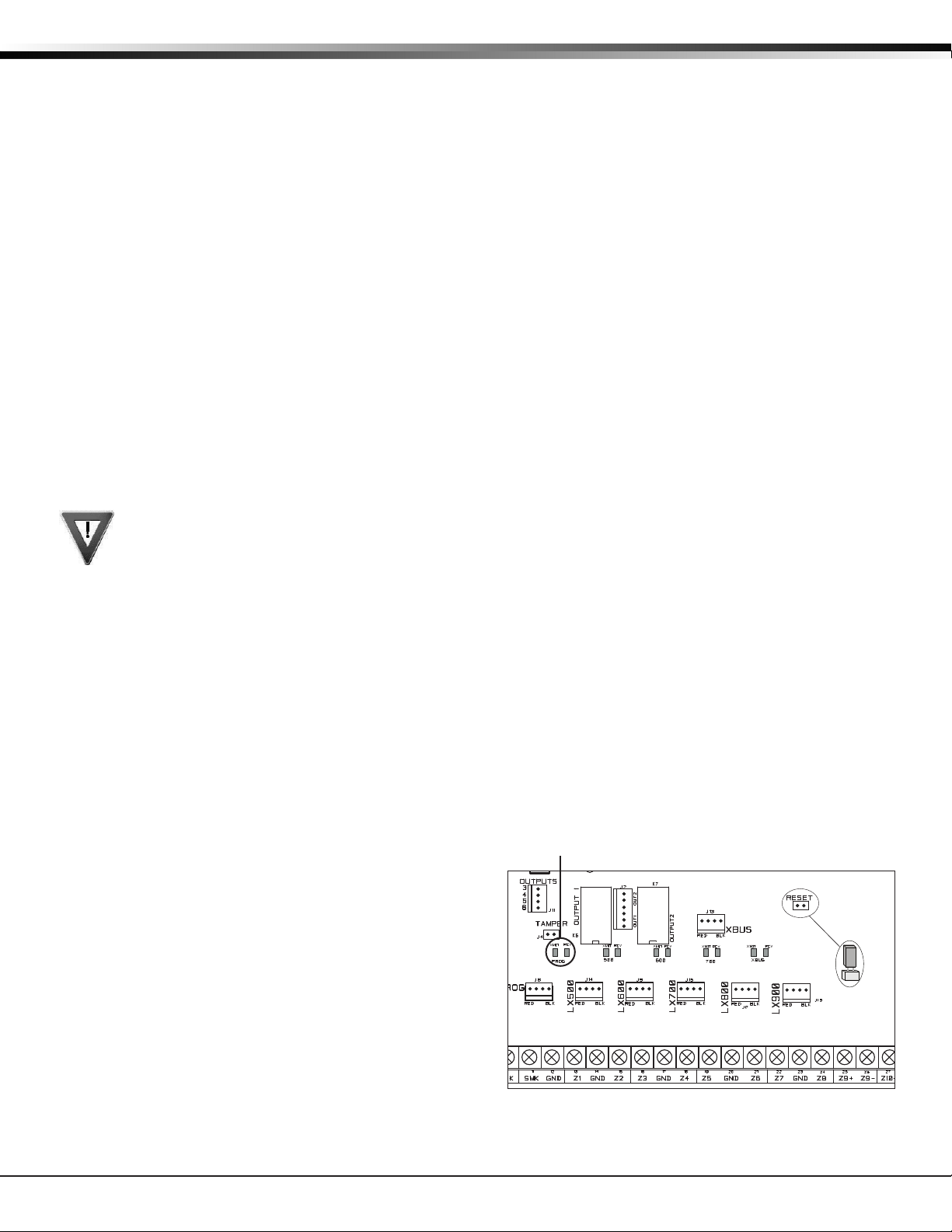
To enable wireless keypad association operation on the
XR150INT/XR550INT panel reset the panel three times
allowing the keypad bus transmit light to begin ashing
between each reset. See Figure 1.
For 60 seconds the panel listens for wireless keypads
that are in RF Survey mode and have not been
programmed or associated into another panel. When
the keypad associates with the panel the keypad logo
LED turns from Red to Green.
Wireless keypads are assigned to the rst open device
position in Device Setup automatically based upon the
order in which they are detected.
Accessing the Programmer
1. Momentarily place the Reset jumper over both of
the RESET pins to reset the panel.
2. Enter the code 6653 (PROG) and press CMD.
3. The keypad displays: PROGRAMMER.
INTRODUCTION
Introduction
Transmit/
Receive LEDs
Figure 1: XR550INT Series Panel Showing
Reset and Transmit/Receive LEDs
XR150/XR550 International Series Programming Guide Digital Monitoring Products
1

INTRODUCTION
1.3 Programmer Operation
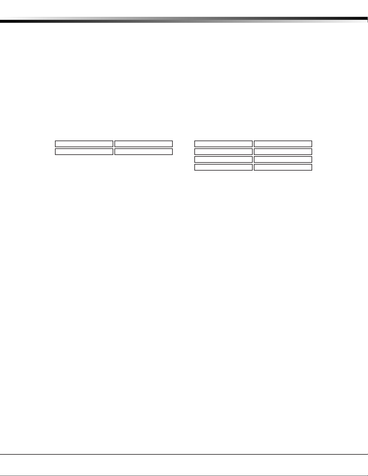
There are 20 programming sections to choose from:
Programming Item Section in This Manual Programming Item Section in This Manual
Initialization 2 Output Information 12
Communication 3 Output Groups 13
Network Options 4 Menu Display 14
Device Setup 6 PC Log Reports 16
Remote Options 7 Area Information 17
System Reports 8 Zone Information 18
System Options 9 Stop 19
Bell Options 10 Set Lockout Code 20
Output Options 11 Feature Upgrade 21
To choose a section for programming, press any select key or area when the keypad displays the name of that
section. Sections 2 through 21 contain detailed instructions for each programming step.
1.4 Programmer Lockout Codes
The panel allows you to enter the programming function without entering a lockout code using steps 1 to 4 listed
in Getting Started. We recommend, however, that you install a Lockout Code to restrict programming to only those
persons your company authorizes. You can do this by using the SET LOCKOUT CODE feature in the Programmer. The
Lockout Code restricts any unauthorized panel programming.
After resetting the panel and entering the code 6653, the keypad displays PROGRAMMER. Press CMD to advance
through the programming sections until SET LOCKOUT CODE displays (after STOP). Press any select key or area. The
keypad displays ENTER CODE: – . Enter a 3 to 5 digit Programmer Lockout Code and press CMD. The keypad displays
ENTER AGAIN followed by ENTER CODE: –. Enter the same 3 to 5 digit code a second time and press CMD. The
keypad displays CODE CHANGED.
Note: The Lockout Code range is 100-65535. The panel does not accept a 5-digit Lockout Code higher than 65535.
Before accessing programmer functions enter the new code number. Write the Lockout Code number down and
keep it in a secure place with access limited to authorized persons only. Lost Lockout Codes require the panel to be
sent back to DMP for repair. You may cancel a Lockout Code by entering 00000 at the Set Lockout Code command.
1.5 Reset Timeout
The panel has a feature that requires you to enter the Programmer within 30 minutes of resetting the panel. After
30 minutes, if you attempt to program by entering the 6653 (PROG) code, the keypad displays: RESET PANEL. You
must reset the panel and enter the program code then begin programming within the next 30 minutes.
If you are already in the Programmer and do not press any keys on the programming keypad for 30 minutes, the
panel terminates programming. All data entered up to that time is not saved unless you run the Stop routine.
Note: Use the Stop routine to exit panel Programming. Ensure the keypad displays “SAVING PROGRAM” to save all
programming changes entered.
Digital Monitoring Products XR150/XR550 International Series Programming Guide
2

1.6 Power Up
Key
When the panel is powered up after an AC power failure, any zone transitions are not recognized for 60 seconds.
Normal zone processing resumes at the end of the 60 seconds.
1.7 Keypads
DMP oers multiple keypads in a variety of styles that provide programming capabilities. Each keypad and its
operation are shown and described in the following sections. See Figures 2 through 4.
32-Character Display
INTRODUCTION
32-Character Display
and Proximity Antenna
Backlit Logo
SMITH RESIDENCE
FRI 12:51 PM
Data Entry Digit Keys
Select Keys
CMD Key
Back Arrow
Power LED
Armed LED
Backlit Logo
and Proximity
Antenna
JONES RESIDENCE
12: 51
FRI
Data Entry Digit keys
PM
Select Keys
COMMAND Key
Back Arrow Key
Figure 3: Thinline Keypad
Figure 2: Wireless Keypad
Interactive
Shield
Dealer
Logo
Local
Weather
TODAY
TUESDAY
CURRENT
82
HI LO
98 77
HI LO
98 77
DISARMED
Panic
Chime
Reset
Favorites
Proximity
Reader
Carousel
Menu
Figure 4: Graphic Touchscreen Keypad
1.8 Special Keys
The following special keys/areas are common to all DMP keypads.
COMMAND (CMD) Key
Pressing CMD allows you to go forward through the programming menu and through each step of a programming
sec tion. As you go through the programming, the keypad display shows any current programming already stored in
the panel memory. If no change is required for an option, press CMD to advance to the next step.
CMD is also used to enter information into the panel’s memory such as phone numbers or zone names. Press CMD
after entering information.
Back Arrow (<—) Key
Use the Back Arrow key to back up one step while programming. The Back Arrow key is also used when an error is
made while entering in formation. Press the Back Arrow key once to erase the last character entered.
Select Keys or Areas
The top row of keys are called the select keys on Thinline keypads or select areas on Graphic Touchscreen keypads.
Each time you need to press a select key or area, the keypad displays the function or options above one of the keys
or in the select area. Displaying choices above individual select keys or in select areas allows them to be used for
many dierent applications. For example, you can enter AM or PM when programming the automatic test time or
answer YES or NO for a system option.
During programming, the select keys or areas also allow you to change infor mation currently in panel memory by
pressing the appropriate select key or area under or on the display. You then enter the new information using the
keypad data entry digit keys.
When there are more than four re sponse options avail able, press CMD to display the remaining options. Pressing the
Back Arrow key allows you to review the previous four choices.
The select keys or areas are also used for choosing a section from the pro gramming menu. Press any select key or
touch the select area when the programming section name you want displays.
XR150/XR550 International Series Programming Guide Digital Monitoring Products
3

INTRODUCTION
Note: On Wireless, Thinline and Aqualite keypads, when instructed to press the rst select key, press the far left
select key; the second select key is the second from the left; third select key is second from the right; and the
fourth select key is the far right key. See Figure 6.
On Graphic Touchscreen Keypads, when instructed to press the rst select key, touch select area 1; the second
select key touch select area 2; third select key touch select area 3; and the fourth select key touch select area 4.
See Figure 6.
(CBA
First Letter
Second Letter
Figure 5: Thinline/Aqualite/Wireless Select Keys
Third Letter
Special Character
1.9 Entering Characters Using the Number Pad
1. Choose a character from the table.
2. Identify the Number the character correlates with
and press it on the number pad.
3. Identify the Select Key or Area for the character and
press that select key or area on the keypad. Press the
select key or area again to display a lowercase letter.
4. When the desired character displays on the keypad,
return to Step 1 to enter another character or press
CMD if nished.
1.10 Keypad Displays Current Programming
Each programming option displayed at the keypad shows
the currently selected option in the panel memory. These
options are either shown as a number, a blank, or a NO
or YES. To change a number or blank to a new number, press any select key or touch any select area. The current
option is replaced with a dash.
Press the number(s) on the keypad you want to enter as the new number for that option. It is not necessary to
enter numbers with leading zeros. The panel automatically right justies the number when you press CMD.
To change a programming option that requires a NO or YES response, press the select key or touch the select area
for the response not selected. See Figure 7.
For example, if the current option is selected as YES and you want to change it to NO, on Thinline or Aqualite
keypads press the third select key. On Graphic Touchscreen keypads touch select area 3. The display changes to NO.
Press CMD to display the next option.
Select Area 2
Select Area 1
32-Character Display
Figure 6: Graphic Touchscreen Select Areas
NUMBER
1 A B C ( [ {
2 D E F ) ] }
3 G H I ! ^ ~
4 J K L ? “ |
5 M N O / \ `
6 P Q R & $
7 S T U @ %
8 V W X , =
9 Y Z
0 - + . ‘ * < # >
1 2 3 4
Select Area 3
Select Area 4
SELECT KEY OR AREA
space
:
_ ;
Thinline,
Aqualite,
Press the black colored top
row Select key/area.
THEN
YESBELL TST
The keypad displays the new
selection. Press CMD to advance.
NOBELL TST
Wireless
Keypads
Graphic
Keypads
YESBELL TST
NOBELL TST
Figure 7: Changing the Current Programming Option
Digital Monitoring Products XR150/XR550 International Series Programming Guide
4
1.11 Multiple Displays
For many programming and user options, such as Area selections, Menu Displays, and Status Lists, there are several
displays containing programming. For example, when programming Menu Displays, keypads 1 through 16 display
on two separate displays. First, keypads 1 through 8 display. Press CMD to display keypads 9 through 16. This same
scheme is used for areas 1 through 32.
Note: Areas not pre-programmed at installation to display at this keypad cannot be viewed.
1.12 Asterisks in Programming
Asterisks display next to a programming option that is already selected. As shown in the example, options that are
selected to display the current programming selection have an asterisk next to the number. Those that are not
selected simply display the number. In the Devices example, keypads 3, 8, 9, and 15 are not selected. In the Areas
example, areas 3, 8, 9, 15, 19, 23, 25, and 31 are not selected. In both examples the numbers with asterisks are
selected.
To select or deselect a number, simply enter the number using the digit keys on the keypad. This same scheme is
used when viewing the panel armed status and other programming and operational functions. Remember to press
CMD to display the rest of the device or area numbers.
Devices
*1 *2 3 *4
*5 *6 *7 8 *13 *14 15 *16
9 *10 *11 *12
1.13 Compliance Instructions
This product incorporates eld-programmable software. Refer to the XR150INT/XR550INT Compliance Listing Guide
(LT-1330INT) for additional compliance information.
INTRODUCTION
Areas
*1 *2 3 *4 *17 *18 19 *20
*5 *6 *7 8 *21 *22 23 *24
9 *10 *11 *12 25 *26 *27 *28
*13 *14 15 *16 *29 *30 31 *32
XR150/XR550 International Series Programming Guide Digital Monitoring Products
5

INITIALIZATION
Initialization
NOTE: When any panel programming is changed, the STOP function must be performed and SAVING PROGRAM must display on
the keypad in order ot save the programming changes. See Stop.
2.1 Initialization
2.2 Clear All Memory
2.3 Clear All Codes
2.4 Clear All Schedules
2.5 Clear Display Events Memory
2.6 Clear Zone Information
2.7 Clear Area Information
2.8 Clear Output Information
2.9 Clear Communication and Remote Options
2.10 Clear Wi-Fi
INITIALIZATION
INIT ALL? NO YES
SURE? YES NO
CODES? NO YES
SURE? YES NO
SCHEDS? NO YES
SURE? YES NO
EVENTS? NO YES
SURE? YES NO
ZONES? NO YES
SURE? YES NO
AREAS? NO YES
SURE? YES NO
OUTPUTS? NO YES
SURE? YES NO
COM/RMT? NO YES
SURE? YES NO
WIFI? NO YES
SURE? YES NO
This function allows you to clear selected parts of the panel program back to the factory
defaults in preparation for system programming. Run the initialization function on all new
installations.
For each section of the panel program you
can initialize, a NO or YES option is provided.
CODES?
Selecting NO advances
you to the next prompt.
SCHEDS?
NO - Leaves existing programming intact then displays Clear All Codes.
YES - Clears all memory then displays Reset Panel. Reset the panel by shorting RESET and
re-enter programming mode to continue.
NO - Leaves existing codes intact.
YES - Clears the user code and user prole memory and assigns user code number 99 to the
highest user position.
Note: The user name for the default user code is created using the current programmed
primary user language.
NO - Leaves existing schedules intact.
YES - Clears all shift, and output schedules.
NO - Leaves existing event memory intact.
YES - Clears the events memory.
NO - Leaves existing zone information intact.
YES - Clears the zone information for all zones. All zones are marked * UNUSED * and must
be renamed before being able to display on any system keypad.
NO - Leaves existing area information intact.
YES - Clears the area information for all areas. All areas are marked * UNUSED * and must
be renamed before being able to display on any system keypad.
NO - Leaves existing output information intact.
YES - Clears all programmed Output names and any output cuto assignment.
NO - Leaves existing communication and remote options intact.
YES - Reset communication and remote options programming to factory defaults.
NO YES
NO YES
Selecting YES advances you to
a confirmation prompt.
SURE?
If you select YES, the panel initializes that section of
the program and advances you to the next prompt.
If you select NO, the panel advances you to the next
section prompt but does not initialize that section of
the program.
YESNO
NO - Leaves existing Wi-Fi programming intact.
YES - Reset Wi-Fi programming to factory defaults.
2.11 Set to Factory Defaults
DEFAULTS NO YES
SURE? YES NO
NO - Leaves existing panel programming intact.
YES - Sets the panel’s programming back to factory default selections. Selecting YES does
not clear the panel’s event memory, zones, user code information, or schedules.
Note: Sets the Programming and User language to English.
Digital Monitoring Products XR150/XR550 International Series Programming Guide
6

Communication
3.1 Communication
3.2 Account Number
3.3 Transmit Delay
3.4 Communication Path
3.5 Communication Type
3.6 Path Type
3.7 Test Report
3.8 Test Frequency
COMMUNICATION
ACCOUNT NO: 12345
XMIT DELAY: 30
PATH: -
COMM TYPE: NONE
NONE DD NET CID
CELL WIFI
PATH TYPE: BACKUP
PRIMARY BACKUP
TEST RPT: YES
NO YES DEFER
TEST FREQ: 1 DY
Congure the communication options for the panel. The information you program varies
with the Communication Type you select.
The Account Number is a 1 to 5 digit number used to identify which panel is sending a
message. Enter the account number sent to the SCS-1R Receiver. Messages may be sent to a
central station or via PC Log Reports to a PC. The default is 12345.
NET, CELL, and DD - The range of valid account numbers for a panel is 100-65535. A range
of valid account numbers for a CID path is 1-9999. For accounts of four digits or less, do not
enter leading zeros.
Enter the number of seconds (15 to 45) the panel waits before sending burglary zones
(Night, Day, or Exit) reports to the receiver. Other zone type reports are sent immediately.
Alarm bells and relay outputs are not delayed during this period. Program Burglary Outputs
for pulsed or steady, and set Abort Reports to YES if Opening and Closing reports are not
being sent. Enter 0 (zero) to disable this function. The default is 30.
If the area where the alarm occurred is disarmed during the Transmit Delay time, only an
Abort Report (S45) message is sent to the receiver. If the area where the alarm occurred
is disarmed after the alarm message is sent to the receiver but before the Bell Cuto
time expires even if the alarm was silenced, an Alarm Cancelled (S49) message is sent.
Otherwise the alarm is sent at the end of the delay. The Alarm Cancelled report cannot be
disabled.
Up to eight communication paths may be programmed. Each path is designated as a
primary or backup communication route. Path 1 is always Primary but other paths may be
programmed as additional primary or backup.
Each primary path establishes a new path group. A path group is made up of the primary
path and its subsequent backup paths. Typical communication takes place on the primary
path with backup paths being used only when the primary path fails or when the backup
path is programmed to duplicate messages. There is no option to backup path 8.
Species the communication method the panel uses on this path to report system events to
DMP SCS-1R, SCS-VR Receivers or non-DMP receivers. Default is NONE for Path 1, and NONE
for Path 2-8.
NONE - For local systems. Selecting NONE ends communication programming.
DD - Digital Dialer communications to a DMP SCS-1R Receiver.
NET - Network communication using the panel onboard network connection. The DMP
Network/Output reporting format is transmitted over a data network to the SCS-1R or SCSVR Receiver.
CID - This option allows the panel to communicate to DMP receivers using the Contact ID
format.
CELL - This option allows communication over the cellular network using a cellular
communicator.
WIFI - Network communication to DMP Model SCS-1R or SCS-VR Receivers.
The Path Type denes if the path is Primary or Backup. Because Path 1 is Primary, this
option only displays for paths 2-8. Default is Backup.
Note: If the Primary Communication Type is CELL, then the backup Communication Type
can only be NET.
Test Report determines if test reports are sent on this path. Reports are sent according to
the programming in Test Frequency and Test Time. Default is YES.
Select YES to allow the programmed test report to be sent on the path currently being
programmed.
Select DEFER to not send a test report if the panel communicates any message to the
receiver within the time set in Test Frequency. Select NO to not send test reports on this
path.
Test Frequency determines the frequency of the test report. Enter a number from 1 to 60
and select DY (Day) or HR (Hour) by pressing the far right select key or area. Default is 1
DAY.
COMMUNICATION
XR150/XR550 International Series Programming Guide Digital Monitoring Products
7

COMMUNICATION
3.9 Test Day
3.10 Test Time
3.11 Check In
3.12 Fail Time
3.13 Encryption (XR550INT with Encryption only)
3.14 IPV6 Address
TEST DAY: SUN
Use this option to set the day of the Test Report. This option appears only when Test Report
is Yes, Test Frequency is Day and a multiple of seven. Press CMD to display the rst four days
of the week. Press CMD to display the last three days. Select the day of the week to send
the test report. Default is SUNDAY.
TEST TIME:
0:00 AM
CHECKIN: NO YES
CHECKIN:
NO YES RND ADPT
Select ADP3 (Adaptive 3) for a backup path to adapt using a 3 minute Check-in and Fail
CHECKIN:
ADP3
When YES is selected, enter the number of minutes between check-in reports, from 2
CHECKIN MINS: 200
FAIL MINS: 240
ENCRYPT: NO
NO 128 256
USE IPV6:
NO YES
Use this option to select the time of day for Test Reports. Select the hour, minute and AM/
PM. Enter 0:00 AM to disable this feature. Default is 0:00 AM.
This option displays if the COMM TYPE is NET or CELL. Check-in reports are a method of
supervising the panel for communication with the receiver. For NET the default is YES. For
CELL the default is YES.
Select RND (Random) for the panel to check-in at random times from 6 to 60 minutes when
all areas are disarmed. If any area is armed a check-in is sent every 6 minutes.
Select ADPT (Adaptive) for a backup path to adapt to the check-in programming from
this groups primary path if the primary path becomes unavailable. Check-in programming
includes Check-in and Fail Time.
Time if the primary path becomes unavailable. This option also indicates a Communication
Trouble (S10) if the cell tower is unavailable for 3 minutes.
to 240 for NET or 3 to 240 for CELL, when the panel is armed or disarmed. For CELL the
default is 0. For NET the default is 200.
This option displays if CHECKIN is set to YES. Entering a FAIL TIME allows the receiver to
miss multiple check-ins before logging that the panel is missing. The maximum fail time is
240 minutes. For example, if CHECKIN is 10 and FAIL TIME is 30, the receiver only indicates
a Panel Not Responding after 30 minutes. The FAIL TIME must be equal to or greater than
the CHECKIN time. Default is equal to CHECKIN for CELL. Default is 240 for NET.
This option displays only if the Communication Type is NET or CELL. Select 128 or 256 to enable
the encryption level for the path currently being programmed. Default is NO.
Note: 256-bit encrypted messages to the SCS-1R receiver only communicate when using
SCS-104 Receiver Line Cards with Version 102 or higher software.
This prompt determines if the network path uses IPV6 for communication.
3.15 Receiver IP
3.16 Receiver Port
3.17 First Telephone Number
Digital Monitoring Products XR150/XR550 International Series Programming Guide
8
RECEIVER IP
000.000.000.000
RECEIVER PORT -
Enter the receiver port number. Valid range is 1 to 65,535. Default is 2001.
2001
FIRST PHONE NO.
This option displays only if the Communication Type is NET or CELL. Enter the Receiver
IP address where the panel sends network messages. The Receiver IP Address must be
unique and cannot be duplicated on the network. Enter all 12 digits and leave out the
periods. For example, enter IP address 192.168.0.250 as 192168000250. The periods display
automatically.
This option displays only if the Communication Type is DD or CID.
This is the rst number the panel dials when sending reports to the receiver. Phone
numbers can have two lines of 16 characters each to equal up to 32 characters.
Enter P to program a three-second pause in the dialing sequence. The P character counts as
part of the 32 allowable characters.
Enter R as the rst character for rotary (pulse) phone function. The R character counts as
part of the 32 allowable characters.
Call Waiting: You can place the “* 7 0 P” (Star, Seven, Zero, Pause) in the telephone
number rst position to cancel Call Waiting. For example, program NET with second line
DD and phone number *70P555-1212, and you have NET with Call Waiting cancelled on the
second line.
Caution: A call waiting cancel programmed on a non-call waiting telephone line
would prevent communication to the central station.

COMMUNICATION
3.18 Second Telephone Number
3.19 Advanced Programming
3.20 APN
3.21 Fail Test Hours
3.22 Protocol
3.23 Retry Seconds
3.24 Substitution Code
3.25 893A
SECOND PHONE NO.
ADVANCED? NO YES
APN
SECURECOM400
FAIL TEST HRS: 0
PROTOCOL: TCP
RETRY SECONDS: 6
SUB CODE: NO
NO YES SHARED
893A: NO YES
The panel dials the second number when two successive tries using the rst number fail. If
the panel cannot reach the receiver after two attempts using the second number, it returns
to the rst number and makes two additional attempts. A total of ten dialing attempts are
made using the rst and second phone num bers.
Each number can be up to 32 characters in length in cluding any P or R char acters entered
for pause or rotary connections or call waiting cancel option.
Should all ten attempts fail, the panel continues to attempt sending the message using
the next programmed path. If all programmed communication paths fail, the panel clears
the communication buer and makes one communication attempt each hour to send a
TRANSMIT FAILED (S87) report to the receiver. Access the User Menu Display Events feature
to view the report information not sent to the receiver or download the report with DMP
Remote Link™ software.
Select Yes to enter the Advanced Programming menu for the communication path currently
being programmed.
Enter the rst APN (Access Point Name). This allows an access point for cellular
communication and is used to connect to a DNS network. The APN may contain two lines of
16 characters to equal 32 characters. Default is set to SECURECOM400.
Note: This option is not used when a 263C CDMA Cellular Communicator is used for
communication.
This option sets the frequency for a Backup or Adaptive path to send a test report when the
closest previous path fails within its path group.
For example, if a backup path is programmed to send a weekly test report and the Fail Test
Frequency is set to 2 hours, when the previous path fails within its group, the backup path
starts sending a test every 2 hours until the previous path restores. If Fail Test Frequency is
set to 0, test reports are sent only according to Test Report programming. Range is 0 to 24
hours. Default is 0.
This option displays only when Communication Type is NET.
Select TCP to communicate over the network using TCP protocol. Select UDP to
communicate using UDP protocol. Default is TCP.
This option displays for NET Communication.
Enter the number of seconds (between 6 and 15) the panel should wait before retrying to
send a message to the receiver if an acknowledgment was not received. The panel retries
as many times as possible for a period of one minute before sending a network trouble
message. For example, if retry time is set to 15, the panel retries four times.
The default Retry Time is 6 seconds.
This option displays when the Communication Type is NET or CELL. The Panel Substitution
Code increases the level of security by helping to ensure that the panel sending the
message to the receiver has not been substituted by another panel. The default is NO.
Select YES to send a substitution code with every message.
Select SHARED (SHR) to use the same substitution code as operating in the previous path.
This option displays when the Communication Type is DD or CID.
2ND LINE PREFIX:
-
The 893A option allows reports to be sent to the receiver on a second DD line using the
893A module. Default is NO.
When using this option, Test Report messages (S07 Automatic Recall Test or S88.
Unrestored System Recall Test) are sent to the receiver at the frequency programmed
in Test Frequency, alternating between the rst and second phone line.
For example, a DD path with an 893A module set for daily test report frequency sends
a test report through phone line 1 one day and phone line 2 the next day.
If the 893A option is set to YES, enter up to a 3-digit prex to be dialed before the
second phone number. If no prex is entered, the second phone number is dialed as
originally entered.
3.26 Alarm Switch
ALARM SWITCH: 1
This option displays for DD or CID Communication Types.
Enter the number of attempts to send an alarm message before switching to the next path.
Range is from 1 to 10. All non-alarm messages are sent for 10 attempts on the dialer before
a switch is initiated. If the path immediately following this channel is not a backup path,
this option has no eect. Default is 1.
XR150/XR550 International Series Programming Guide Digital Monitoring Products
9

COMMUNICATION
3.27 Duplicate Alarms
3.28 Alarm Reports
3.29 Supervisory/Trouble Reports
3.30 Opening/Closing and User Reports
3.31 Door Access Report
3.32 Panic Test (Network only)
3.33 Send Communication Trouble
3.34 Send Path Information
DUPLICATE ALARMS
NO YES
ALARM YES
NO YES FIRE
SPV/TRBL YES
When YES is selected, the following reports are sent for all zone types:
NO YES FIRE
O/C USER NO YES
DOOR ACS DENY
Select YES to enable Door Access Granted and Denied reports to this receiver whenever
NO YES DENY
PANIC TST NO YES
SEND COMM TRBL:
This option displays for each path and determines if and how communication trouble on
NO YES
SEND PATH INFO:
This option displays for each path and if YES, each panel message includes path information
NO YES
This option displays for BACKUP paths. If Yes is selected, the current backup path
duplicates all alarms occurring on its group primary path. Default is NO.
This option displays when the Path Type is Primary. All backup paths within the group follow
the same programming for Alarm Reports. Default is YES.
When YES is selected, the following reports are sent to the receiver for all zone types:
• Alarm • Bypass • Reset • Restore
When FIRE is selected, the following reports are sent for Fire, Fire Verify and Supervisory
Zones:
• Alarm • Bypass • Reset • Restore
This option displays when the Path Type is Primary. All backup paths within the group follow
the same programming for Supervisory/Trouble Reports. Default is YES.
• Trouble • Low Battery • Missing • Fault
• Restorals • System Troubles • System Restoral
When FIRE is selected, the following reports are sent for Fire, Fire Verify, and Supervisory
Zones:
• Trouble • Low Battery • Missing • Fault
• Restorals • System Troubles • System Restoral
Serviceman reports are sent regardless of the selection made for Supervisory/Trouble
reports.
This option displays when the Path Type is Primary. All backup paths within the group follow
the same programming for Opening/Closing and User Reports. Default is YES.
When YES is selected, the following reports by user are sent to this receiver.
• Opening • Code changes (including adding, deleting, changing)
• Closing • Schedule changes (temporary, permanent, shift)
• Bypass • Holiday date changes
• Reset
This option displays when the Path Type is Primary. All backup paths within the group follow
the same programming for Door Access Reports. Default is DENY.
a door access is granted to a user. The Door Access Granted report is only sent if the
keypad number has also been selected in Access Keypads under the SYSTEM REPORTS
programming.
Select DENY to enable Door Access Denied reports only to this receiver when a door access
is denied to a user.
YES allows the panic zone test verication and failure results to be sent to the central
station receiver. NO disables the panic test report. The default setting is NO. The system
test start, stop, panic zone verication, and panic zone failure messages sent to the
central station and the trips count operation are the same as used under the Walk Test. See
Using the Walk Test section in the Appendix.
the path is sent to the receiver. A trouble message indicates both the path number and
communication type that failed. Default is YES.
such as path number, communication type, and path type. Default is NO.
Digital Monitoring Products XR150/XR550 International Series Programming Guide
10

Network Options
Network Options are provided to dene the network conguration for the panel. This information will be used
during communication of messages via network.
Note: Wi-Fi must be selected as Communication Type in the Communication section for Wi-Fi Setup to display.
Note: IP addresses and port numbers may need to be assigned by the network administrator. When entering an IP,
Gateway, or Subnet Mask address be sure to enter all 12 digits and leave out the periods. For example, IP address
192.168.000.250 is entered as 192168000250.
4.1 Network Options
4.2 WiFi Setup
4.2.1 WPS
4.2.2 List
4.2.3 Manual
NETWORK OPTIONS
WPS LIST MANUAL
TEST
SEARCHING .
WPS LIST MANUAL
SEARCHING
SIGNAL
HOMENET123
W/L SECURITY:
WPA-PSK
W/L SECURITY:
WEP WPA NONE
W/L KEY:
*****************
W/L KEY:
-
WPS LIST MANUAL
WIFI SETUP
ENTER SSID
SSID:
SSID FOUND
▐▐▐▐▐▐▐
This option is for conguring the desired network settings. Press any select key or area to
select.
This option is for connecting to the desired Wi-Fi network and will display only when Comm
Type is set to Wi-Fi. Press any select key or area to select.
WPS LIST MANUAL displays. Press the rst select key or area to choose WPS to
automatically connect to a WPS enabled router. Press the second select key or area to
choose LIST and see the name and signal strength of any Wi-Fi routers in range. Press the
third or fourth select key or area to choose MANUAL and enter the name of the Wi-Fi router
you wish to connect to. Pressing CMD displays TEST. To select TEST press the rst select key
or area to verify connection of your system to the Wi-Fi network.
When WPS is selected, SEARCHING displays. Press the WPS button on the Wi-Fi network
router to which you are attempting to connect. SEARCHING displays for up to two minutes
or until connected to the WPS enabled router. Refer to the router’s instruction manual for
sending a security key to the XR150INT/XR550INT Series panel.
If the panel fails to connect to the WPS enabled router, WPS FAILED RETRY? NO YES
displays. Press the fourth select key or area to RETRY or press the third select key or area
to display WPS LIST MANUAL.
When LIST is selected, SEARCHING displays until any Wi-Fi networks are found in range.
Once available Wi-Fi networks are found the keypad displays the name of the SSID (Wi-Fi
Network name) and signal strength of each network. Press CMD to scroll through the list of
available Wi-Fi networks. When the desired network is displayed, press any select key or
area to connect.
Note: If the panel is unable to detect the security type, W/L SECURITY with the default
security type WPA-PSK displays. If a dierent security type is required, press CMD and WEP
WPA NONE displays. Press the select key or area of the desired security type to choose.
When connecting to the Wi-Fi network the panel also detects the security type in use and
W/L KEY: *************** displays.
Enter the W/L KEY and the panel performs a connection test and CONNECTING displays.
When successful, CONNECTED displays on the keypad. If the panel does not connect to the
Wi-Fi network, NOT CONNECTED displays. Press CMD to return to the Wi-Fi SETUP main
screen.
This option allows you to enter the desired network name using the keypad. When MANUAL
is selected, the current settings display. Press CMD to continue with no change. SecureCom
is the default.
Use the number keys on the keypad to enter a new or dierent SSID (Wi-Fi Network name),
there is no need to press the select keys or areas. Once the SSID is entered, press CMD and
SEARCHING displays.
When an SSID is entered for the rst time or changed, the panel searches for the SSID
entered to ensure communication. The keypad displays SSID FOUND or SSID NOT FOUND.
When the SSID is found, the security type is also detected.
Note: Depending on the security type, the SSID might take several seconds to process.
Enter up to 32 characters for the SSID from the network router to identify the network LAN.
The SSID is blank by default. Use the chart below to enter lowercase or special characters.
Each successive press of the select key or area gives additional options. For example, to
enter Me5%, you would press key # 5, select key or area 1 (M); press key # 2, select key or
area 2 twice (e); press key # 5 (5); press key # 7, select key or area 4 twice (%).
NETWORK OPTIONS
XR150/XR550 International Series Programming Guide Digital Monitoring Products
11

NETWORK OPTIONS
Key Number Select Key or
1 A, a, B, b C, c (, [, {
2 D, d E, e F, f ), ], }
3 G, g H, h I, i !, ^, ~
4 J, j K, k L, l ?, ", |
5 M, m N, n O, o /, \, `
6 P, p Q, q R, r &, $
7 S, s T, t U, u @, %
8 V, v W, w X, x , =
9 Y, y Z, z space, : _, ;
0 -, + ., ' *, < #, >
SSID:
SSID NOT FOUND
4.2.4 Test
4.3 Wireless Security Type
4.4 Wireless Network Key
4.5 IPV6
4.6 DHCP
4.7 Local IP Address
4.8 Gateway Address
4.9 Subnet Mask
4.10 DNS Server
4.11 734N Listen Port.
TEST
W/L SECURITY:
WPA-PSK
W/L SECURITY:
WEP WPA NONE
W/L KEY:
*****************
W/L KEY:
-
USE IPV6:
NO YES
DHCP NO YES
LOCAL IP ADDRESS
Enter the local IP address. The Local IP Address must be unique and cannot be duplicated.
192.168.0.250
GATEWAY ADDRESS
Enter the local gateway address. The Gateway IP Address is needed to exit your local
192.168.0.1
SUBNET MASK
Enter the local subnet mask assigned to the panel. The default subnet mask address is
255.255.255.000
DNS SERVER
Enter the IP address of the DNS (Domain Name System) used by the panel to resolve domain
192.168.0.1
PORT: 2002
While searching, SEARCHING displays on the keypad. If the 763 is unable to connect to the
desired network and SSID NOT FOUND displays, press CMD to return to the main menu and
WPS LIST MANUAL displays. Press CMD again to display TEST.
Enter the Wireless Network Key for the network and press CMD to save the key.
Press the rst select key or area to select TEST and the 763 will attempt to verify
connection of your system to the desired Wi-Fi network.
When successful, W/L SECURITY displays. Select the security type based on the network
router programming. The default network security type is WPA-PSK. Press any select key or
area to display the other security options. The available options are WEP, WPA, and NONE.
Press the rst select key or area to choose WEP, press the second select key or area for
WPA, press the third select key or area for NONE.
This option displays only if Comm Type is set to Wi-Fi and Security option is not set to
NONE. Enter the key provided from the network router’s programming. WEP requires
a network password of 10 characters (WEP64) or 26 characters (WEP128), using a
combination of the number 0-9 and the letters A-F (See the chart above to enter lowercase
or special characters).
WPA/WPA-PSK uses a custom key that allows 8 to 32 characters.
Note: Depending on the security type, the key might take several seconds to process.
At the IPV6 prompt, select YES to use an IPV6 address. The default is NO. IPV6 is DHCP
only.
If the panel uses a dynamic IP address select YES. When set to YES, the panel operates
using DHCP and does not use the Local IP Address number. When the DHCP option is set to
NO, the panel uses the IP address entered in Local IP Address. The default value for DHCP
mode is YES.
The default local IP address is 192.168.0.250.
network. The default gateway address is 192.168.0.1.
255.255.255.000.
names into IP addresses. The default address is 192.168.0.1.
area 1
Select Key or
Enter the port number that the 734N/734N-POE will use to send communication to
the panel. This must be the same port that is programmed in Panel IP Port within the
734N/734N-POE Communication programming menu.
Note: The 734N Listen Port cannot be the same as the panel network programming port.
4.12 734N Passphrase
734N PASSPHRASE
-
Enter an 8 to 16-character Passphrase to encrypt communication with the
734N/734N-POE module. The 734N Passphrase must match the 734N Passphrase entered in
Communication programming of the 734N. The Passphrase is blank by default.
Note: A passphrase is required for operation.
area 2
Select Key or
area 3
Select Key or
area 4
Note: When
\ is entered,
the keypad
displays ¥.
When ~ is
entered, ->
displays.
Digital Monitoring Products XR150/XR550 International Series Programming Guide
12

Device Setup
5.1 Device Setup
5.2 Custom Card Denitions
Wiegand Code Length
5.2.1 Site Code Position
5.2.2 Site Code Length
5.2.3 User Code Position
5.2.4 User Code Length
5.2.5 Require Site Code
5.2.6 Site Code Display
5.2.7 Number of User Code Digits
DEVICE SETUP
CARD OPTIONS
DMP CUSTOM ANY
WIEGAND CODE
LENGTH: 26
SITE CODE
POSITION: 1
SITE CODE
LENGTH: 8
USER CODE
POSITION: 9
USER CODE
LENGTH: 16
REQUIRE SITE
CODE? NO YES
SITE CODE 1:
(0-16,777,214) 127
SITE CODE 1: -
NO. OF USER CODE
DIGITS: 5
This section allows you to dene the panels physical conguration. You can install and
address up to sixteen supervised devices on the keypad data bus.
Select the slot number (1-8) that you would like to program a custom non-DMP card format
into. The format that is programmed into slot 1 is the default format. In the event that a card
with an unrecognized format is used, that card will be read in the format that is programmed
in slot 1. To restrict card reads to specic formats, only program slots 2-8. For a chart of
commonly used card formats and their defaults, refer to the 734 Installation Guide (LT-0737)
or 734N/734N-POE Installation Guide (LT-1197).
If you select slot 1 and are updating an XR with rmware Version 182 or earlier, Format
Name will automatically be named Single Card Format and Wiegand Code Length will default
to 45.
When using a custom credential, enter the total number of bits to be received in Wiegand
code including parity bits.
Press any select key or area to enter a number between 1-255 to equal the number of bits.
Default is 26 bits.
Typically, an access card contains data bits for a site code, a user code, and start/stop/
parity bits. The starting position location and code length must be determined and
programmed into the 734INT/734NINT/734N-POE Module.
Enter the site code start position in the data string. Press any select key or area to enter a
number between 0-255. Default is 1.
Enter the number of characters the site code contains. Press any select key or area to
enter a number between 1-16. Default is 8.
Dene the User Code start bit position. Press any select key or area to enter a number
between 0-255. Default is 9.
Dene the number of User Code bits. Press any select key or area to enter a custom
number. On a 734 module, custom numbers can only be between 16-40.
On a 734NINT/734N-POE module, custom numbers can be between 1-255. Default is 16.
Press the select key or area under YES to use a site code.
In addition to User Code verication, door access is only granted when any one site code
programmed at the SITE CODE ENTRY option matches the site code received in the Wiegand
string.
734INT Module: You can program up to 8 eight-digit site codes. Site code range is 0-999.
Any previously programmed site codes display. Dashes represent blank site codes. Default is
blank.
734NINT/734N-POE Module: You can program up to 8 eight-digit site codes. Site code
range is 0-16,777,214. Any previously programmed site codes display. Site Code 1 defaults
to 127. Site Codes 2-8 default to blank. Dashes represent blank site codes.
Site Code 1 displays rst. Enter a site code number followed by CMD to advance to the next
option, Site Code 2. To delete an existing site code, press any select key or area. Either
enter a new site code followed by CMD, or press CMD to leave blank and continue to the
next site code. Repeat these steps to change, delete, or add up to 8 site codes.
The 734, 734N/734N-POE, and 734N-POE module recognizes user codes from 4-12 digits in
length. The 734NINT
/734N-POE
module recognizes user codes from 1-12 digits in length.
DEVICE SETUP
01110101101101010001100111
First Bit
Received
Position = 0
XR150/XR550 International Series Programming Guide Digital Monitoring Products
Site Code
Position = 1
Length = 8
In this example the Wiegand Code Length = 26 bits.
User Code
Position = 9
Length = 16
Last Bit
Received
Position = 25
13

DEVICE SETUP
Press any
select key or area
to enter a user code digit length. This number must match the
user code number length being used by the panel. Default is 5. For an Area System, use 4 to
12 digits (typically 5).For all other systems and panels, use 4 digits.
Any selection above 5
digits require entry of the custom card denitions with custom site and user code positions
for the Wiegand string. When searching the bit string for the user code, the digits are iden-
tied and read from left to right.
5.3 Device Number
DEVICE NO:-
Enter the address of the device you are programming. If using a wireless keypad, program
the device number in the Status List Auxiliary 1 Zones programming option to display
wireless keypad troubles. After you program each option for the rst keypad, repeat these
programming steps for each additional keypad. The valid range for KEYPAD, FIRE, and
EXPANDER type devices is 1 -16. The valid range for DOOR type devices is 1 - 16 and 501 -
961. See the AX Bus Addresses and 734 Zone Numbers chart on the previous page. Wireless
keypads and network door controllers are not able to occupy address 1.
DOOR Device Type
The XR550INT provides the ability to program an additional 16 doors of access to the
system using 734, 734N, and 734N-POE Wiegand Interface Modules connected to any of the
XR550INT’s LX-Bus headers. This can be combined with the 16 doors of access available
from the keypad bus for a total of 32 doors. Door capacity can be increased to a maximum
of 64 or 96 by applying purchased feature keys. Feature keys are purchased through DMP
Customer Service and entered into the panel using a keypad or Remote Link. Call DMP
Customer Service at 1-866-266-2826 for purchasing information.
Programming and Operation
Once a 734 address has been programmed for the bus, the LX-Bus is automatically
converted from a hardwire zone expansion bus to a hardwire Access Expansion Bus (AX-Bus)
and the bus begins to operate as shown below.
• Each 734 module provides one door relay and four protection zones to connect switches
such as door and window contacts.
• 16 doors of access can be programmed per AX-Bus to a maximum of eighty (80) 734
modules. Please see the table below for available addresses.
• Any unused AX-Bus zone numbers may be programmed as wireless zones. Hardwired
zone expansion modules such as the 711, 714, 715-16 and others are incompatible with
bus operation and cannot be used.
• Device Setup programming for AX-Bus address are automatically programmed as a door
type. Device Type, Communication Type and Display Areas are not shown. Only 734
module programming is shown.
Note: An AX-Bus operation is compatible with 734, 734N, and 734N-POE modules and
the Model XR550INT. Keypads must only be used on the keypad bus. AX-Bus operation is
incompatible with the Model XR150INT control panels.
Device Addresses and 734, 734N, and 734N-POE Zone Numbers
Keypad Bus LX/AX Bus
Device/
Door
1 11-14 501 501-504 601 601-604 701 701-704 801 801-804 901 901-904
2 21-24 505 505-508 605 605-608 705 705-708 805 805-808 905 905-908
3 31-34 509 509-512 609 609-612 709 709-712 809 809-812 909 909-512
4 41-44 513 513-516 613 613-616 713 713-716 813 813-816 913 913-916
5 51-54 517 517-520 617 617-620 717 717-720 817 817-820 917 917-920
6 61-64 521 521-524 621 621-624 721 721-724 821 821-824 921 921-924
7 71-74 525 525-528 625 625-628 725 725-728 825 825-828 925 925-928
8 81-84 529 529-532 629 629-632 729 729-732 829 829-832 929 929-932
9 91-94 533 533-536 633 633-636 733 733-736 833 833-836 933 933-936
10 101-104 537 537-540 637 637-640 737 737-740 837 837-840 937 937-940
11 111-114 541 541-544 641 641-644 741 741-744 841 841-844 941 941-944
12 121-124 545 545-548 645 645-648 745 745-748 845 845-848 945 945-948
13 131-134 549 549-552 649 649-652 749 749-752 849 849-852 949 949-952
14 141-144 553 553-556 653 653-656 753 753-756 853 853-856 953 953-956
15 151-154 557 557-560 657 657-660 757 757-760 857 857-860 957 957-960
16 161-164 561 561-564 661 661-664 761 761-764 861 861-864 961 961-964
Zones
Device/
Door
Zones
Device/
Door
Zones
Device/
Door
Zones
Device/
Door
Zones
Device/
Door
Zones
Digital Monitoring Products XR150/XR550 International Series Programming Guide
14

DEVICE SETUP
5.4 Device Name
5.5 Device Type
5.6 Device Communication Type
5.7 Serial Number
5.7.1 Supervision Time
5.8 Access Areas
5.9 Egress Areas
XR150/XR550 International Series Programming Guide Digital Monitoring Products
* UNUSED *
TYPE: KEYPAD
DOOR KPD FI EXP
DEVICE COMM TYPE
KPD-BUS AX-BUS
DEVICE COMM TYPE
NETWORK WLS
SERIAL#: XXXXXXXX
SUPRVSN TIME: 240
SELECT MINUTES:
0 60 240
ACCESS AREAS:
1 2 3 4
5 6 7 8
EGRESS AREAS:
A device name must be given to each device in the system. To add a device name, press
any select key or area. The default device name (DEVICE X) displays. Select CMD to
accept the default name or press any select key or area to enter a new name up to 32
alphanumeric characters. Press CMD.
To remove a device from the system, delete the device name by pressing any select key or
area, then press CMD. The panel automatically programs the name as
* UNUSED *.
This section allows you to select a device type for the selected device number.
KEYPAD - The device type is a non-re, non-access keypad.
DOOR - The device is an access control device and is either a keypad using door strike
functions or a Wiegand Interface Module. Devices with an address higher than 16 are
automatically assigned as a DOOR device type.
FIRE - The device is a 630F Remote Annunciator.
Note: See Fire Device Remote Programming in the XR550INT Series Compliance Guide (LT-
1330INT) for instructions on how to allow remote panel programming.
EXPANDER - The device is a Zone Expansion Module.
KEYPAD - Select KPD-BUS for wired keypads or select WIRELESS for wireless keypads.
Default is KPD-BUS.
DOOR - For wired devices, select KPD BUS for addresses 1-16 or select AX BUS for addresses
501-964. For network devices, select NETWORK.
Note: This option only displays if Device Type is KEYPAD and Device Comm Type is
WIRELESS.
Enter the eight-digit serial number found on the wireless keypad.
Note: This option only displays if Device Type is KEYPAD and Device Comm Type is WIRELESS.
Press any select key or area to select the supervision time required for the device. Press
CMD to accept the default time. Default is 240 MINUTES.
Press the select key or area under the required number of minutes. The device must check
in at least once during this time or a missing condition is indicated for that device. Zero (0)
indicates an unsupervised wireless keypad.
Note: When the panel is reset, panel is powered down and powered up, or programming is
complete, the supervision timer restarts for all wireless keypads.
Press CMD to program Access Areas. To select an area, enter the area number using the
digit keys on the keypad. When an area is selected, an asterisk appears next to the area
number. Enter the number again to deselect the area. Press CMD to display the next set of
areas. Refer to the Multiple Displays section at the beginning of this document.
Users must have matching access area numbers assigned to their code to receive a door
access at this device.
If you do not enter any area numbers, all users with Door Access authority receives a door
access without regard to schedules. If the user code is programmed for Anti-Pass YES, then
the user is logged into all matching areas. This user is not allowed to access these areas
again until they have egressed the area. See Egress Areas.
When all areas accessed by a door are armed, the door is locked by the panel.
Note: For an All/Perimeter, Home/Sleep/Away, or Home/Sleep/Away with Guest system,
Access Areas should be left at factory default settings.
Press CMD to program Egress Areas. To select an area, enter the area number using the
digit keys on the keypad. When an area is selected, an asterisk appears next to the area
number. Enter the number again to deselect the area. Press CMD to display the next set of
areas. Refer to the Multiple Displays section at the beginning of this document.
Note: For an All/Perimeter, Home/Sleep/Away, or Home/Sleep/Away with Guest system,
Egress Areas should be left at factory default settings. If an area is programmed as an
access area, it cannot be programmed as an egress area and therefore does not display
during Egress Areas programming.
Use this option to detect Anti-passback violations. Anti-passback requires a user to properly
exit (egress) an area they have previously accessed. If users fail to exit through the proper
card reader location they are not granted access on their next attempt.
Users must have matching access area numbers assigned to their prole, to receive a door
access at this device. If the user is programmed for Anti-Pass YES, then the user is
15

DEVICE SETUP
logged out of all matching areas. This allows the user to again access the area. See Access
Areas section.
If you do not enter any area numbers, all users with Door Access authority receives a door
access without regard to schedules. If you are not using the Anti-Pass feature leave Egress
Areas blank.
5.10 Display Areas
DISPLAY AREAS:
*1 *2 *3 *4
*5 *6 *7 *8
*9 *10 *11 *12
*13 *14 *15 *16
*17 *18 *19 *20
*21 *22 *23 *24
*25 *26 *27 *28
*29 *30 *31 *32
Press CMD to program Display Areas. To select an area between 1 to 32, enter the area
number using the keypad digit keys. When an area is selected, an asterisk appears next to
the area number. Enter the number again to deselect the area. Press CMD to display the
next set of areas. Default is all area numbers. Refer to the Multiple Displays section at the
beginning of this document.
Display Areas allows the panels burglary activities to be segmented so that only specic
area(s) and their associated operation appear at a particular keypad. Area number(s)
selected in this eld aect the way users interact with the system from this particular
device. For example: Program Device 1 to show only the zone activities and armed status
of Area 1.
Enter the area number(s) that this keypad is to display. This allows specic area control
from specic keypads, as well as annunciation of zones assigned to those area(s). When
Display Areas is left defaulted (all areas selected), Menu Display and Status List items
determine whether zone alarms and troubles display at this device, regardless of area
assignment. Also, all system areas may be armed and disarmed from this device.
Note: For an All/Perimeter or Home/Sleep/Away system, Display Areas should be left at
factory default settings.
For Home/Sleep/Away with Guest arming systems, the Display Areas selection determines
which system the keypad arms and disarms. With areas 1, 2 or 3 being the rst areas
selected, the keypad is assigned to the Main system. With area 4, 5 or 6 being the rst
areas selected, the keypad is assigned to the Guest 1 system. With area 7, 8 or 9 being the
rst areas selected, the keypad is assigned to the Guest 2 system (Guest 2 only applies to
XR550INT systems). Keypads can have additional areas assigned for Event Display.
User Action Allowed
When an area(s) is selected, the following user actions are allowed:
• Arming or Disarming of the area(s) selected from the ARM or DISARM menu
• Alarm Silence for the area(s) selected
• Zone Bypass of zones assigned to the area(s) selected
• Zone Monitor of zone assigned to the area(s) selected
• Shift schedule changes allowed for the area(s) selected
• Closing Check Schedule Extend is allowed for the area(s) selected
• Door Schedules changes are allowed for devices that have a matching area(s)
as dened in Device Access Areas
• Door On/O Menu operation is allowed for devices that have a matching area(s)
as dened in Device Access Areas
Note: The previous user actions also require the matching area(s) be programmed in
User Prole: Arm/Disarm area(s).
Status Display Allowed
When an area(s) is chosen, the following displays are allowed:
• Armed Status of the selected area(s)
• Zone Alarms and troubles for burglary (NT, DY, EX, A1, A2) type zones assigned to the
selected area(s)
• Late to Close status of the selected area(s)
• Zone Status (normal/fault) of zones that are assigned to the selected area(s)
Options and Actions Not Aected
The following options are not aected by the Display Areas operation. The User Code
authority level controls access to these items.
• Sensor Reset Menu • Outputs On/O Menu • System Status Menu
• System Test/Panic Test • User Proles • Forgive Anti-Passback
• Service Request • Set System Time and Date
• Fire Drill • Display Events
• 24-hour zones display at keypads based on Status List programming only
Note: A common area and its operations cannot be assigned to a specic keypad.
Display Areas example: When Device 1 has Display Areas set to 20, 21, and 22, it
annunciates troubles and alarms only for zones assigned to those areas.
When arming/disarming from Device 1, only areas 20, 21, and 22 may be armed/disarmed,
even when the User Prole has authority to arm/disarm other system areas.
Exception: Disarming of other areas not selected in Display Areas can be accomplished
by presenting a card that has disarming authority and matching prole areas with areas
assigned in Device Access Areas.
Digital Monitoring Products XR150/XR550 International Series Programming Guide
16

DEVICE SETUP
5.11 Strike Time
5.12 Strike Delay
5.13 Fire Exit Release
5.14 Public Door
5.15 Private Door
5.16 Output Group
5.17 Schedule Override
5.18 Auto Force Arm Device?
5.19 Door Real-Time Status?
STRIKE TIME: 5
STRIKE DELAY: 0
FIRE EXIT NO YES
PUBLIC DR NO YES
PRIVATE DR NO YES
OUT GROUP NO YES
OVERRIDE NO YES
AUTO FORCE ARM
DEVICE? NO YES
DOOR REAL-TIME
STATUS? NO YES
Enter a door access time, between 1 and 250 seconds, during which a keypad or access
control device relay is activated. Magnetic locks or electric door strikes are connected to
the relay and released for the length of the strike time. Default is 5 SECONDS.
Enter 0 (zero) to activate the device relay with a toggle action. This allows the user to
activate or deactivate the device relay each time a valid user code is entered. The device
relay is activated or deactivated until a user code is entered again.
Note: The Request to Exit door access time of a keypad or Model 734INT/734NINT
Wiegand Interface Module is not aected by this selection. It remains at 5 seconds.
Enter the number of minutes, 0 to 9, to delay a door strike after a valid code is entered or
a card read occurs. When a valid code or card read or code is received, the activation of
the door strike is delayed for the number of minutes programmed. The standard door strike
message is sent to the Central Station receiver and logged in the Display Events at the
time of card read or code entry and is not delayed. During this delay, all subsequent codes
entered or cards presented to the reader for a door strike are ignored and no record of the
attempt is stored. Enter 0 (zero) to disable. Default is l.
Select YES to allow the door access relay at this address to be released whenever Fire panic
keys are pressed or a Fire or Fire Verify zone alarm is in the Status List. The relay is reset
whenever a Sensor Reset is performed to remove all Fire and Fire Verify zone alarms from the
Status List. Select NO to not allow the door access relay at this address to be released.
Select YES to allow the door access relay at this address to be locked whenever the Lockdown
command is issued from the keypad User Menu or remote command.
Select NO to not allow the door access relay at this address to be released. Default is NO.
Select YES to assign this address as a private door, which will not be assigned to an access
area. The private door can then be added to a prole. Up to four private doors can be
assigned to an individual prole.
Select NO to not allow a door to be designated as a private door. Default is NO.
Select YES to allow the output group (relays) assigned to the user prole to turn ON when
the device relay is activated for the programmed strike time. This could be used to operate
an elevator control. Default is NO. See the User Proles section in the Appendix of this
document for more information about proles.
Use this option to allow door ON/OFF schedules to be overridden by the armed condition
of the system. Selecting YES causes the on time for a door schedule to be ignored when all
areas assigned to Access Areas for this device are armed. Should any area become disarmed
after the door schedule on time, the device output turns on. A door output which is on
during a disarmed period automatically turns o when all access areas assigned to the
device become armed, even if the scheduled o time has not been reached. This feature
can be used to keep doors locked when a factory opens late, or is forced to close early, due
to a snow storm or other cause. Select NO to allow door schedules to operate independent
of system armed status.
Note: When OVERRIDE is YES and there are no areas programmed in ACCESS AREAS, the
door schedule for that device does not work. Either set OVERRIDE to NO or enter an
area number in ACCESS AREAS.
Select YES to have all Display Areas assigned to this keypad automatically arm and force
arm faulted zones at arming. The user is not prompted to select areas to arm or force arm
faulted zones after choosing ARM at the keypad. If Closing Code is programmed as YES,
only the matching areas between the Display Areas and the User Code’s authorized areas
arm. Also, when YES is selected, the user is not prompted to select areas to disarm after
entering a code at Entry Delay or after choosing Disarm at the keypad. All matching areas
assigned to the User Code and to this keypad are automatically disarmed. When NO is
selected, the user is prompted to select areas (ALL NO YES) and choose to force arm or
bypass at arming and disarming. Default is NO.
Select YES to have real-time door status messages sent to PC Log reporting and Entré
reporting for this device. Messages are sent anytime the panel turns the door relay on or
o. Default is NO.
XR150/XR550 International Series Programming Guide Digital Monitoring Products
17

DEVICE SETUP
5.20 Send Door Forced Message?
5.21 Program 734INT/734NINT Options
5.21.1 Card Options
5.21.2 Activate Zone 2 Bypass
5.21.3 Zone 2 Bypass Time
5.21.4 Relock on Zone 2 Change?
5.21.5 Activate Zone 3 Request to Exit
5.21.6 Zone 3 REX Strike Time
SEND DOOR FORCED
MESSAGE? NO YES
PROGRAM 734
OPTIONS? NO YES
CARD OPTIONS
DMP CUSTOM ANY
ACTIVATE ZONE 2
BYPASS? NO YES
ZONE 2 BYPASS
TIME: 40
RELOCK ON ZONE 2
CHANGE? NO YES
ACTIVATE ZONE 3
REX? NO YES
ZN 3 REX STRIKE
TIME: 5
Select YES to have the panel send a real-time door status message of Forced Open (FO)
to PC Log reporting and Entré reporting when the door relay is o, but the door zone has
transitioned from its normal state. Default is NO.
Select YES to program a 734INT or a 734NINT/734N-POE Wiegand Interface Module. The
options displayed for a 734INT or 734NINT are the same.
To program the 734, the Device Type must be set to DOOR and the Device Communication
Type must be set to KPD-BUS.
To program the 734NINT/734N-POE, the Device Type must be set to DOOR and the Device
Communication Type must be set to NETWORK.
Select DMP to allow only the DMP card format for access. The menu advances to REQUIRE
SITE CODE.
Select CUSTOM to disable DMP format and program slos 1-8 as needed. The menu advances
to FORMAT NO.
Select ANY to allow all Wiegand card reads to activate the door strike relay. The relay is
activated for the length of time programmed in ZN 3 REX TIME. No user code information is
sent to the panel. The menu advances to NO COMM WITH PNL.
Select YES to activate the Bypass option.
Selecting NO allows standard zone operation on Zone 2 and displays the ACTIVATE ZONE 3
REX option. Default setting is NO.
If the door being released by the 734INT/734NINT/734N-POE module is protected (contact
installed), you can provide a programmable Bypass entry/exit timer by connecting its contact
wiring to the 734INT/734NINT/734N-POE module Zone 2. When the on-board Form C relay
activates and the user opens the door connected to Zone 2, the zone is bypassed for the
number of seconds programmed in ZONE 2 BYPASS TIME allowing the user to enter/exit.
If Zone 2 does not restore (door closed) within the programmed bypass time, the
734INT/734NINT/734N-POE piezo pulses during the last ten seconds. If Zone 2 restores prior
to the end of the programmed time, the piezo silences. If the zone does not restore before
the programmed time, the 734INT/734NINT/734N-POE ends the bypass and indicates the
open or short zone condition to the panel.
Enter the number of Bypass seconds to elapse before the Bypass timer expires. Range is
from 20 to 250 seconds. Press any select key or area to enter the number of seconds. If the
door remains open when the timer expires a zone open/short is sent to the panel for Zone
2. The default is 40 seconds.
Selecting NO leaves the relay on for the door access time when Zone 2 restores.
Selecting YES turns the 734INT/734NINT/734N-POE relay o and relocks the door when
Zone 2 changes state. The default is NO.
Selecting YES activates the Zone 3 Request to Exit (REX) option.
Selecting NO allows standard zone operation on Zone 3 and displays the ACTIVATE ONBOARD
SPEAKER option. Default setting is NO.
Optionally connect a PIR (or other motion sensing device) or a mechanical switch to Zone
3 to provide REX capability to the system. When Zone 3 shorts, the on-board Form C relay
activates for the programmed number of seconds. During this time, the user can open the
protected door to start the programmed Bypass entry/exit timer. After the programmed
number of seconds, the relay restores the door to its locked state.
The 734INT/734NINT/734N-POE module provides a bypass-only option for REX on Zone 3.
When Zone 3 opens from a normal state, only a bypass occurs: the on-board relay does not
activate. This bypass-only option uses two methods of REX. The rst REX device provides
the programmed Bypass entry/exit timer. The second REX device, or manual device such as
a door knob, unlocks the door.
An example of the bypass-only conguration is a door to an oce that is locked 24 hours a
day. Users pass a REX motion detector positioned by the door to begin the programmed exit
timer. Within the programmed number of seconds the user must then manually activate a
second device, such as a REX device or manual door knob, to unlock the door.
If the door is opened after the programmed number of seconds, the zone goes into alarm.
Enter the number of REX seconds to elapse. Range is from 5 to 250 seconds. Press any
select key or area to enter the number of seconds. The default is 5 SECONDS.
Digital Monitoring Products XR150/XR550 International Series Programming Guide
18

DEVICE SETUP
5.21.7 Activate Onboard Speaker
5.21.8 No Communication with Panel
ACTIVATE ONBOARD
SPEAKER? NO YES
NO COMM WITH PNL
OFF SITE ANY ON
NO COMM WITH PNL
OFF
NO COMM WITH PNL
SITE
NO COMM WITH PNL
ANY
NO COMM WITH PNL
ON
NO COMM WITH PNL
LAST
Select YES to enable the onboard piezo speaker for local annunciation. Select NO to turn
the piezo o for all operations. This does not aect remote annunciator open collector
(RA) operation. The default is NO.
This option denes the relay action when communication with the panel has not occurred
for approximately ten seconds. Press any select key or area to display relay action options.
Press the Back Arrow key to return to the NO OF USER CODE DIGITS:.
Choose the action required:
Press the rst select key or area to choose OFF [Default] (Relay Always O) — The relay
does not turn on when any Wiegand string is received. O does not aect any REX
operation.
Press the second select key or area to choose SITE (Accept Site Code) — Door access is
granted when the Wiegand site code string received matches any site code programmed at
SITE CODE ENTRY. For details refer back to the REQUIRE SITE CODE option.
Press the third select key or area to choose ANY (Any Wiegand Read) — Door access is
granted when any Wiegand string is received.
Press the fourth select key or area to choose ON (Relay Always On) — The relay is always
on.
Press CMD to display the next action.
Press the rst select key or area to choose LAST (Keep Last State) — The relay remains in
the same state and does not change when communication is lost.
After choosing the action, the NO COMM WITH PNL option and the newly dened action
display. Programming is now complete. Press CMD to display DEVICE NO.
XR150/XR550 International Series Programming Guide Digital Monitoring Products
19

REMOTE OPTIONS
Remote Options
6.1 Remote Options
6.2 Remote Key
6.3 Remote Disarm
6.4 Armed Answer Rings
6.5 Disarmed Answer Rings
6.6 PC Modem
6.7 Alarm Receiver Authorization
6.8 Service Receiver Authorization
6.9 Manufacturer Authorization
REMOTE OPTIONS
REMOTE KEY:
REMOTE DISARM?
ARMED ANSWER
RINGS: 8
DISARMED ANSWER
RINGS: 8
PC MODEM NO YES
ALR RCVR NO YES
SVC RCVR NO YES
MANUFACTURER
AUTH? NO YES
NO YES
This section allows you to enter the information needed for Remote Command/Remote
Programming operation.
This option allows you to enter a code of up to 16 characters. The Remote Link™ program
must give the correct key to the panel before being allowed any remote functions. All
panels are shipped from the factory with the key preset as blank.
To enter a remote key or change the current one, press a
combination of up to 16 digits. Press CMD. The current key displays as asterisks.
YES allows the panel to be disarmed remotely. NO disables remote disarming.
Default is YES.
Enter the number of rings the panel counts before answering the phone line when all
system areas are armed. Any number from 0 to 15 can be entered. If 0 (zero) is entered,
the panel does not answer the phone when all system areas are armed.
The default is 8 (eight).
Answering machine bypass procedure: Entering a number greater than 0 (zero) into either
Armed Rings or Disarmed Rings, allows a central station operator to connect remotely with
the panel.
How it works: The operator calls the panel, allows the telephone to ring one time,
and then hangs up. The panel stores this as an attempt to communicate. The operator
then calls back within 30 seconds. The panel seizes the telephone line to allow remote
programming.
Note: This feature does not interfere with the normal operation of the Arm Rings or Disarm
Rings functions.
Enter the number of rings the panel counts before answering the phone line while any
system areas are disarmed. Any number from 0 to 15 can be entered. If 0 (zero) is entered,
the panel does not answer the phone when any system area is disarmed. The default
number is 8 (eight).
YES allows the panel to answer the telco link and connect with Remote Link through the PC
Modem at 2400 baud. NO disables PC Modem communication.
Select YES to enable remote commands and programming to be accepted from the alarm
SCS-1R Receiver. The Remote Key option can also be required.
With YES selected, the panel requests the receiver key during its rst communication with
the rst SCS-1R Receiver. The panel retains this alarm receiver key in memory and allows
remote commands to be accepted from the alarm receiver. If an alarm occurs during a
remote connect, the alarm report is immediately sent to this receiver only.
When NO is selected, remote commands and programming are not accepted from the alarm
SCS-1R Receiver.
YES enables remote commands and programming to be accepted from a secondary service
receiver other than the alarm SCS-1R Receiver. The Remote Key option can also be
required.
With YES selected, the panel requests the service receiver key the rst time it is contacted
by the service receiver. The panel retains this service receiver key in memory and accepts
remote commands from the service receiver.
If an alarm occurs during a remote connect, the panel disconnects from the service
receiver and calls the alarm receiver. Alarm reports are only sent to the alarm receiver.
It is important that the alarm receiver key and the service receiver key programmed at
the central station are NOT the same so the panel can determine the dierence between
receivers. When NO is selected remote commands and programming are not accepted from
a secondary service receiver.
Select YES to allow DMP Technical Support technicians to access the panel during system
service or troubleshooting. This authorization automatically expires within one hour.
DMP remote service is provided on a read only basis: DMP technicians can look at the
system programming and make suggestions only. Alterations can only be accomplished by
installing company service personnel.
select key or area
and enter any
Digital Monitoring Products XR150/XR550 International Series Programming Guide
20
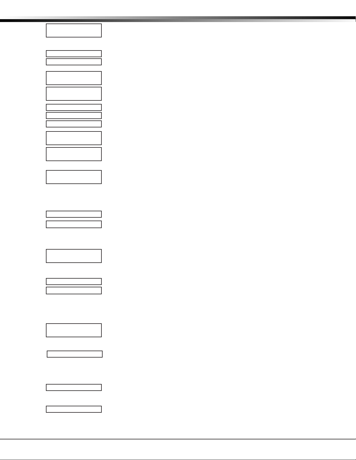
REMOTE OPTIONS
6.10 Allow Network Remote
6.10.1 Network Programming Port
6.10.2 Encrypt Network Remote
6.11 Allow Cellular Remote
6.11.1 APN
6.11.2 Encrypt Cellular Remote
6.12 Entré Connection
6.12.1 Entré Incoming TCP Port
ALLOW NETWORK
REMOTE? NO YES
NETWORK PROG
PORT: 2001
ENCRYPT NETWORK
REMOTE? NO YES
ALLOW CELL
REMOTE? NO YES
APN:
SECURECOM400
-
ENCRYPT CELL
REMOTE? NO YES
ENTRE
CONNECTION: NONE
ENTRE INCOMING
This option displays only if NET is chosen for the Entré connection. Enter the programming
TCP PORT: 2011
This option displays only if the panel has network capability. YES allows remote
programming over the network. Changing this option does not change any other network
programming options. Default is YES.
Enter the programming port number. The programming port identies the port used to
communicate messages from the panel. The default Programming Port setting is 2001.
YES encrypts data sent over network. Default is NO.
YES allows remote programming using cellular connection. Default is YES.
Enter the rst APN (Access Point Name). This allows an access point for cellular
communication and is used to connect to a DNS network. The APN may contain two lines of
16 characters to equal 32 characters. Default is set to SECURECOM400.
YES encrypts data sent over a cellular connection. Default is NO.
This option displays if the panel has network or cellular capability. Select NET to allow a
dedicated network connection with Entré. Options are NONE or NET. Default is NONE.
port number for the incoming Entré connection. The programming port identies the port
used to communicate messages to and from the Entré software. This port cannot be the
same port as programmed in Network Programming Port. The default Programming Port
setting is 2011.
6.12.2 Entré IP Address
6.12.3 Entré Outbound TCP Port
6.12.4 Entré Backup Connection
6.12.5 Entré Backup TCP Port
6.12.6 Entré Reports
Arm and Disarm Reports
Zone Reports
ENTRE IP
000.000.000.000
ENTRE OUTBOUND
TCP PORT: 2001
ENTRE BACKUP
NONE NET CEL
ENTRE BACKUP TCP
This option displays only if NET is chosen for the Entré connection. Enter the backup
PORT: 2001
ENTRE REPORTS
This option displays only if NET is chosen for the Entré connection. Choose which types of
ARM/DIS: NO YES
ZONE: NO YES
This option displays only if NET is chosen for the Entré connection. Enter the Entré IP
address where the panel sends network messages. The Entré IP Address must be unique
and cannot be duplicated on the network. Enter all 12 digits and leave out the periods.
For example, enter IP address 192.168.0.250 as 192168000250. The periods display
automatically. Default is 0.0.0.0
This option displays only if NET is chosen for the Entré connection. Enter the programming
port number for the outbound Entré connection. The programming port identies the port
used to communicate messages to the Entré software. Default is
This option displays if NET or CELL is chosen for the Entré connection. Enter the backup
address where the panel sends network messages if the rst Entré connection fails. The
Entré connection must be unique and cannot be duplicated on the network. If the backup
connection is NET, enter all 12 digits and leave out the periods. For example, enter IP
address 192.168.0.250 as 192168000250. The periods display automatically. Default is
0.0.0.0
programming port number for the outbound Entré connection in case the connection to the
primary IP fails. Default is 2001.
system reports are sent to Entré. Press CMD to view all of the Entré report options. Choose
YES to enable arming/disarming, zone, user code, door access, or supervisory message
reports. All Entré reports default to YES.
Sends arming, disarming and Late to Close events. Includes the area number, name and
action, the user number and name, and the time and date.
Sends changes in the status of active zones. Includes the zone number, name, type, the
action (alarm, trouble, bypass, etc.), user number (if applicable), and area name. For a
Walk Test, Verify and Fail messages are sent for each zone.
2001.
XR150/XR550 International Series Programming Guide Digital Monitoring Products
21
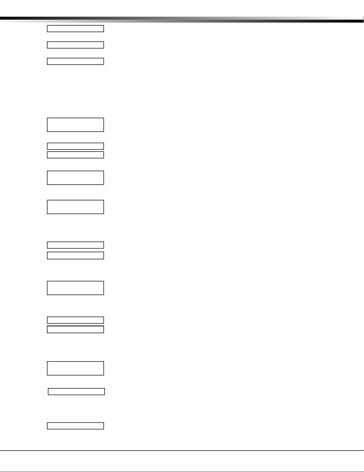
REMOTE OPTIONS
User Command Reports
Door Access Reports
Supervisory Reports
6.12.7 Entré Checkin
6.12.8 Entré Passphrase
6.13 Integrator Connection
6.13.1 Integrator Incoming TCP Port
USR CMDS : NO YES
DOOR ACS: NO YES
SUPV MSG: NO YES
ENTRE CHECKIN
MINUTES: 0
Select the rate at which check-in messages are sent over the Entré connection. Select 0
ENTRE PASSPHRASE
To enable encryption enter an 8 to 16-character Passphrase using alphanumeric characters.
-
INTEGRATOR
CONNECTION: NONE
INTGRTR INCOMING
This option displays only if NET is chosen for the integrator connection. Enter the
TCP PORT: 8011
Sends user code changes, schedule changes, and door access denied events.
Sends door access activity: door number, user number and name, and time and date.
Sends system monitor reports, such as AC and battery, and system event reports.
Supervisory Reports also sends the following reports:
• Abort • Exit Error • Ambush
• System Recently Armed • Alarm Bell Silenced • Unauthorized Entry
• Late to Close*
* Only sent as a Supervisory Report if Area Schedules is not enabled, Closing Check is
enabled, and an opening/closing schedule has been programmed.
Note: To send these reports to the PC Log, you must enable SUPV MSG.
(zero) to disable check in messages. Range is 0, 3-240 minutes. Default is 0.
If you leave the Passphrase blank, the panel communicates with Entré, but the data is not
encrypted. The Passphrase is blank by default.
This option displays if the panel has network or cellular capability. Select NET to allow a
dedicated network connection with the integrator. Options are NONE or NET. Default is
NONE.
programming port number for the incoming connection. The programming port identies
the port used to communicate messages to and from the integrator software. This port
cannot be the same port as programmed in Network Programming Port. The default
Programming Port setting is 8011.
6.13.2 Integrator IP Address
6.13.3 Integrator Outbound TCP Port
6.13.4 Integrator Backup Connection
6.13.5 Integrator Backup TCP Port
6.13.6 Integrator Reports
Arm and Disarm Reports
INTEGRATOR IP
000.000.000.000
INTGRTR OUTBOUND
TCP PORT: 8001
INTGRTR BACKUP
NONE NET CEL
INTGRTR BACKUP TCP
This option displays only if NET is chosen for the integrator connection. Enter the backup
PORT: 8001
INTGRTR REPORTS
This option displays only if NET is chosen for the integrator connection. Choose which
ARM/DIS: NO YES
This option displays only if NET is chosen for the integrator connection. Enter the
integrator IP address where the panel sends network messages. The IP Address must be
unique and cannot be duplicated on the network. Enter all 12 digits and leave out the
periods. For example, enter IP address 192.168.0.250 as 192168000250. The periods display
automatically. Default is 0.0.0.0
This option displays only if NET is chosen for the integrator connection. Enter the
programming port number for the outbound integrator connection. The programming port
identies the port used to communicate messages to the integrator software. Default is
8001.
This option displays if NET or CELL is chosen for the integrator connection. Enter the
backup address where the panel sends network messages if the rst connection fails. The
integrator connection must be unique and cannot be duplicated on the network. If the
backup connection is NET, enter all 12 digits and leave out the periods. For example, enter
IP address 192.168.0.250 as 192168000250. The periods display automatically. Default is
0.0.0.0
programming port number for the outbound connection in case the connection to the
primary IP fails. Default is 8001.
types of system reports are sent to the integrator. Press CMD to view all of the Entré
report options. Choose YES to enable arming/disarming, zone, user code, door access, or
supervisory message reports. All integrator reports default to YES.
Sends arming, disarming and Late to Close events. Includes the area number, name and
action, the user number and name, and the time and date.
Digital Monitoring Products XR150/XR550 International Series Programming Guide
22

SYSTEM REPORTS
Zone Reports
User Command Reports
Door Access Reports
Supervisory Reports
6.13.7 Integrator Checkin
6.13.8 Integrator Passphrase
6.14 Send Local Changes
6.14.1 Remote Change IP
6.14.2 Remote Change Port
6.14.3 Remote Telephone Number
6.15 App Key
ZONE: NO YES
USR CMDS : NO YES
DOOR ACS: NO YES
SUPV MSG: NO YES
INTGRTR CHECKIN
MINUTES: 0
Select the rate at which check-in messages are sent over the integrator connection. Select
INTGRTR PASSPHRASE
To enable encryption enter an 8 to 16-character Passphrase using alphanumeric characters.
-
SEND LOCAL
CHANGES? NO
SEND LOCAL
NO NET DD
REMOTE CHANGE IP
000.000.000.000
REMOTE CHANGE
PORT: 2002
REMOTE PHONE NO.
-
-
APP KEY:
Sends changes in the status of active zones. Includes the zone number, name, type, the
action (alarm, trouble, bypass, etc.), user number (if applicable), and area name. For a
Walk Test, Verify and Fail messages are sent for each zone.
Sends user code changes, schedule changes, and door access denied events.
Sends door access activity: door number, user number and name, and time and date.
Sends system monitor reports, such as AC and battery, and system event reports.
Supervisory Reports also sends the following reports:
• Abort • Exit Error • Ambush
• System Recently Armed • Alarm Bell Silenced • Unauthorized Entry
• Late to Close*
* Only sent as a Supervisory Report if Area Schedules is not enabled, Closing Check is
enabled, and an opening/closing schedule has been programmed.
Note: To send these reports to the PC Log, you must enable SUPV MSG.
0 (zero) to disable check in messages. Range is 0, 3-240 minutes. Default is 0.
If you leave the Passphrase blank, the panel communicates with the integrator, but the
data is not encrypted. The Passphrase is blank by default.
This option allows the panel to automatically update Remote Link at the central station
with any changes made to the panel.
Select NET or DD to send local programming changes or User Menu changes to user codes,
user proles, schedules, or holiday dates to Remote Link after exiting the programming or
User Menu. If NET is selected, changes are sent using Network. If DD is selected, changes
are sent using Dialer. Default is NO to disable this feature.
This option displays when NET is selected for Send Local Changes. Enter the IP address
containing up to 12 digits. The Net IP Address must be unique and cannot be duplicated
on the network. Enter all 12 digits and leave out the periods. For example, enter IP
address 192.168.0.250 as 192168000250. The periods display automatically. Default is
000.000.000.000
This option displays when NET is selected for Send Local Changes. Enter the Port number.
Valid numbers are from 0 to 65535. Default is 2002.
This option displays when DD is selected for Send Local Changes. Press CMD to
enter the phone number the panel dials when sending programming changes. After entering
a phone number, the panel sends any panel changes to Remote Link.
The phone number can have two lines of 16 characters each to equal 32. Enter a P to
program a two second pause in the dialing sequence. The P character counts as part of the
32 allowable characters. Enter *70P as the string rst characters to cancel call waiting. Dial
tone detect is an automatic panel function.
Enter the 8-digit App Key obtained in your Dealer Settings tab at DMPDealerAdmincom.
This option is a security feature of the Virtual KeypadTM App used only when your Dealer
Settings at DMPDealerAdmin.com have “EASYconnect” set as the Communication Type.
This communication option is only available for panels with onboard network and is used to
eliminate the need for a static IP address programmed in Network Options. To enter a new
App Key, press any select key or area and enter any combination of 8 digits. Press CMD. The
default for this option is blank.
XR150/XR550 International Series Programming Guide Digital Monitoring Products
23

SYSTEM REPORTS
System Reports
7.1 System Reports
SYSTEM REPORTS
Select specic system reports the panel sends to the receiver.
7.2 Abort Report
7.3 Restoral Reports
7.4 Bypass Reports
7.5 Schedule Change Reports
ABORT NO YES
YES allows the panel to send an alarm abort report to the receiver any time an area is
disarmed during Transmit Delay before an alarm report is sent and the Bell Cuto Time has
not expired. After disarming an area, if any other area remains armed and has zone(s) in
alarm, the alarm abort report is not sent.
If the communication type is set to DD, a Warning: Alarm Bell Silenced report is also sent if
the alarm bell is silenced.
Note: Abort Reports are not sent for Fire, Fire Verify, or Supervisory type zones.
RESTORAL: YES
This option allows you to control when and if a zone restoral report is sent to the central
station receiver. Press any select key or area to display the following options:
NO - Disables the zone restoral report option. Zones continue to operate normally but do
NO YES DISARM
BYPASS NO YES
SCHD CHG NO YES
not send restoral reports to the receiver.
YES - Enables the zone restoral report option. Zone restorals are sent whenever a zone
restores from a trouble or alarm condition.
DISARM - Causes the panel to send restoral reports for a non-24-hour zone whenever a zone
that has restored from a trouble or alarm condition is disarmed. All 24-hour zones send
restoral reports as they restore.
YES allows the panel to send all zone bypasses, resets, and force arm reports to the
receiver. The bypass report includes the zone number, zone name, and the user name
and number of the individual operating the system. Reports are only sent if O/C User in
Communications is set YES for Receiver 1 or Receiver 2.
YES allows the panel to send all schedule changes to the receiver. The report includes the
day, opening time, closing time, extend schedule time, and the user name and number of
the individual making the change. Schedule changes made through Remote Link™ are not
sent to the printer or Display Events.
7.6 Code Change Reports
7.7 Access Keypads
7.8 Ambush
7.9 Late To Open
7.10 Early To Close
CODE CHG NO YES
ACCESS KEYPADS:
*1 *2 *3 *4
*5 *6 *7 *8
*9 *10 *11 *12
*13 *14 *15 *16
AMBUSH NO YES
LATE TO OPEN
MINUTES: 0
EARLY TO CLOSE
MINUTES: 0
YES allows the panel to send all code additions, changes, and deletions to the receiver.
The code change report includes the user name and number added or deleted and the user
name and number of the individual making the change. Code changes made through Remote
Link™ are not sent to the printer or Display Events. Reports are only sent if O/C User in
Communications is set YES for Receiver 1 or Receiver 2. The default setting is YES.
Select the keypad addresses (1 through 16) that send door access reports to the receiver.
Enter the keypad number using the digit keys. An asterisk next to the number indicates
that the keypad is selected. Press CMD to display the next set of keypads.
A report is sent with each door access made from the selected keypads. Keypads at
addresses not selected still operate the door relay but do not send access reports. The
report includes the user number, user name, keypad address, and device name.
YES allows an ambush report to be sent anytime user code number 1 is entered at a
keypad. NO disables the ambush report and allows user number 1 to operate the same as
all other codes.
Enter 1-240 as the number of minutes to elapse that the system may remain armed
after the opening time of a schedule without sending a Late To Open message. If the
system continues to be armed after the Late to Open minutes expire, a Late To Open
message is sent to the central station. Default is 0, which disables the Late To Open
option.
Enter 1-240 as the number of minutes that the system can be armed prior to the
scheduled closing time. If the system is armed prior to the Early to Close minutes, an
Early To Close message is sent to the central station. Default is 0, which disables the
Early to Close option.
Digital Monitoring Products XR150/XR550 International Series Programming Guide
24

System Options
SYSTEM OPTIONS
8.1 System Options
8.2 System
8.3 Instant Arming
8.4 Closing Wait
8.5 Entry Delay 1
8.6 Cross Zone Time
8.7 Zone Retard Delay
XR150/XR550 International Series Programming Guide Digital Monitoring Products
SYSTEM OPTIONS
SYSTEM: AREA
AREA A/P H/A GST
INST ARM NO YES
CLS WAIT NO YES
ENTRY DLY 1: 30
ENTRY DLY 2: 60
ENTRY DLY 3: 90
ENTRY DLY 4: 120
CRS ZONE TM: 4
RETARD DELAY: 10
This section allows you to select system-wide parameters.
This option allows you to program how the areas operate for arming and disarming. The
options you can choose are listed below:
AREA - All 32 areas can be programmed and operated independently.
ALL/PERIMETER - Area 1 is the Perimeter and Area 2 is the Interior.
HOME/SLEEP/AWAY - Area 1 is the Perimeter, Area 2 is the Interior, and Area 3 is the
Bedrooms. With the HOME/SLEEP/AWAY option, the user can:
1. Select HOME to arm just the perimeter.
2. Select SLEEP to arm the perimeter and interior (non bedroom areas).
3. Select AWAY to arm all three areas.
Note: A Home/Sleep/Away system can be congured to use all three areas or only use
the Home and Away areas.
HOME/SLEEP/AWAY WITH GUEST- This allows the alarm system to be divided into a main
house HOME/SLEEP/AWAY system and two other guest houses that also are set up as HOME/
SLEEP/AWAY systems.
Areas 1, 2, and 3 are the Perimeter, Interior, and Bedrooms for the Main house system.
Areas 4, 5, and 6 are the Perimeter, Interior, and Bedrooms for the Guest 1 house system.
Areas 7, 8, and 9 are the Perimeter, Interior, and Bedrooms for the Guest 2 house system.
These areas are automatically assigned per system and cannot be changed. See Display
Areas in Device Setup to assign keypads to a system. Zones are assigned to a system by
assigning the system’s area numbers to the zone in Zone Information programming.
When either All/Perimeter or Home/Sleep/Away is selected, the area names are
automatically assigned and cannot be modied.
Note: Areas 3-32 in an All/Perimeter system, areas 4-32 in a Home/Sleep/Away system,
and areas 9-32 in a Home/Sleep/Away with Guest system are not available for use and
are initialized.
When YES is selected, the arming keypad displays INSTANT for selection during the exit
countdown delay when arming fewer than all areas of the system. At the time instant
arming is selected, any entry and exit delays programmed for the areas being armed are
ignored. The entry delay for previously armed areas is not aected by instant arming.
When NO is selected, INSTANT does not display during arming. Default is NO for an Area
System, and YES for an All/Perimeter or Home/Sleep/Away system.
When YES is selected, the keypad displays ONE MOMENT... while waiting for an
acknowledgement from the receiver before arming the selected area(s) and performing a
Bell Test (if selected). Exit delays begin after the Closing Wait. Opening/Closing reports
must be YES to enable Closing Wait.
Enter the Entry Delay time for all Exit type zones programmed to use Entry Delay 1. When
an armed Exit type zone is faulted, the keypad prewarn tone begins sounding. All keypads
programmed to prewarn for that zone display ENTER CODE:- and the name of the zone
causing the entry delay. When the rst digit of a code is entered, the prewarn tone stops
at that keypad. If an invalid code is entered, the prewarn tone begins sounding again. The
area must be disarmed before the delay expires or an alarm report is sent to the receiver
and an alarm sounds. All zones in that area are delayed along with the Exit zone. Entry
Delay times can be from 30 to 250 seconds. Repeat the above for each entry delay being
used in the system.
Note: Specic Exit Error operation is based on the Entry Delay used (1-4) with an EX
type zone. See Exit Delay. For UL Installations, the combined Transmit Delay (Abort
Window) and Entry Delay must not exceed one (1) minute.
Enter the time allowed between zone faults. When zones are cross zoned, the same zone
or a second cross zoned zone must fault within this time in order for an alarm report for
both zones to be sent to the receiver. If the cross zone time expires without the second
zone faulting, only a zone fault from the rst zone is reported. Cross-zone time can be
from 4 to 250 seconds. Entering 0 (zero) disables this function. Default is 4.
See the Appendix.
Enter the retard time assigned to Fire, Supervisory, Auxiliary 1, Auxiliary 2, Arming, and
Panic type zones. The retard delay only functions when the zone is shorted. The zone must
remain shorted for the entire length of the retard delay before being recognized by the
panel. The Zone Retard Delay can be from 1 to 250 seconds. Entering a zero disables this
function.
25

SYSTEM OPTIONS
8.8 Power Fail Delay
8.9 Swinger Bypass Trips
8.10 Reset Swinger Bypass
8.11 Zone Activity Hours
8.12 Time Zone Changes
8.13 Latch Supervisory Zones
PWR FAIL HRS: 1
SWGRBYPS TRIPS: 2
RST SBYP NO YES
ZN ACTY HRS: 0
TIME CHG NO YES
HRS FROM GMT: 6
When time zone is programmed YES, enter the number (0-23) that indicates the dierence
GMT
LATCH SV NO YES
City/Time Zone GMT City/Time Zone
London, Monrovia, Lisbon, Dublin, Casablanca, Edinburgh 13 New Caledonia
0
Cape Verde Island, Azores 14 Guam, Sydney
1
Mid-Atlantic, Fernando de Noronha 15 Tokyo, Seoul
2
Buenos Aires, Georgetown, Brasilia, Rio de Janeiro 16 Hong Kong, Singapore
3
Atlantic Time (Canada), Caracas, La Paz, Santiago 17 Bangkok, Hanoi
4
Eastern Time (US, Canada) Bogota, Lima, Arequipa 18 Dhaka, Almaty
5
Central Time (US, Canada), Mexico City, Saskatchewan 19 Islamabad, Karachi
6
Mountain Time (US, Canada), Edmonton 20 Abu Dhabi, Kazan
7
Pacic Time (US, Canada), Tijuana 21 Moscow, Bagdad
8
Alaska 22 Eastern Europe
9
Midway Island, Samoa, Hawaii* 23 Rome, Paris, Berlin
11
Fiji, Marshall Island, Wellington, Auckland, Kwajalein, Kamchatka
12
*Arizona, Hawaii, American Samoa, Guam, Puerto Rico, and the Virgin Islands do not observe daylight savings time.
This option tracks the duration of an AC power failure. When the AC power is o for the
length of the programmed delay time, an AC power failure report is sent to the receiver.
The delay time can be from 1 to 15 hours. Entering a 0 (zero) sends the power failure
report after a 15-second delay. The default setting is 1.
Enter the number of times (1-6) a zone can go into an alarm or trouble condition within one
hour be fore being auto matically bypassed. Bypassed zones are auto matically reset when
the area they are assigned to is disarmed. All 24-hour zones are reset when any area of the
system is dis armed. A programming Stop operation restores a bypassed zone. Entering 0
(zero) disables this function. Default is 2.
How it works
The panel hour timer starts at 59 minutes past the hour. If the hour timer expires before
the trip counter is exceeded, the trip counter returns to 0 (zero). If the trip counter is
exceeded before the hour expires, the zone is auto matically bypassed by the panel. A
Bypass Re port is sent to the receiver if Bypass Re ports is YES.
When YES is selected, an auto matically bypassed zone is reset if it remains in a normal
condition for one complete hour after being bypassed. A report of the automatic reset is
sent to the receiver if Bypass Reports has been se lected as YES. Default is NO.
This option provides supervision of a person living alone for non-activity. Enter the number
of hours, 0 to 9, allowed to elapse without a disarmed zone being tripped before a message
is sent to the receiver. Default is 0 (zero).
When the system is disarmed, the timer begins to countdown the number of hours
programmed. Each time activity occurs, the timer restarts the countdown.
Before the countdown time expires, the keypad sounds a tone and PRESS ANY KEY displays
to allow the user to restart the activity timer. The duration of the tone is the number of
seconds programmed for Entry Delay 2.
Select the SUPV/TRBL receiver option in communication programming to send S93 ALARM:
User Activity Not Detected, S94 Alert: Activity Check Enabled, and S95 Alert: Activity Check
Disabled messages.
When an open/close schedule is programmed, the timer only counts down during the
scheduled open period. Also, when a schedule is programmed, if the timer is counting down
and the scheduled open time occurs, the timer resets and begins the countdown again.
This function allows the panel to request automatic time changes from the DMP
SCS-1R Receiver on Path 1. For the receiver to send time changes, it must be programmed
to send time changes and must be receiving time change updates from the network
automation computer at least every 24 hours. Default is YES.
between the Greenwich Time zone (GMT) and where the panel is located. The default is 6.
Selecting YES latches supervisory zone alarms on the keypad display until the sensor reset
operation is performed. Selecting NO automatically clears the alarm from the
display when the supervisory zone restores to a normal condition. Default is YES.
keypad
Digital Monitoring Products XR150/XR550 International Series Programming Guide
26

SYSTEM OPTIONS
8.14 Programming Menu Language
8.15 User Menu and Status List Language
8.16 Bypass Limit
PROG LANGUAGE
Press CMD to select the programming language. Any changes in PROG LANGUAGE do not
take eect until the STOP routine completes.
The current primary programming language displays. The default language is ENGLISH.
PRI LANG: ENGLSH
Select the primary programming language.
ENG SPN FRN CZE
GRE DUT
DUT = Dutch (NEDER)
The current secondary programming language displays. Selecting a secondary language
SEC LANG: NONE
Select the secondary programming language.
ENG SPN FRN CZE
GRE DUT
DUT = Dutch (NEDER)
USER LANGUAGE
The current primary user language displays. The default language is English. Press any
PRI LANG: ENGLSH
ENG SPN FRN CZE
Select the primary user language.
GRE DUT
DUT = Dutch (NEDER)
SEC LANG: NONE
The current secondary user language displays. Selecting a secondary user language allows
Select the secondary user language.
ENG SPN FRN CZE
GRE DUT
DUT = Dutch (NEDER)
BYPASS LIMIT 0
Press a Select key to change the primary programming language.
ENG = English (ENGLISH)
SPN = Spanish (ESPANOL)
FRN = French (FRANCAIS)
CZE = Czech (CESKY)
EΛΛ = Greek (EΛΛHNI)
allows the installer to view programming in English, Spanish, French, Czech, or Greek.
When the Programming Menu is accessed, the installer is prompted to choose the
programming display language. If SEC LANG: is set to NONE, the option to choose a
language does not display. To select a secondary language, press the select key or area
below the language.
Default is NONE.
NONE = No secondary language options are displayed
ENG = English (ENGLISH)
SPN = Spanish (ESPANOL)
FRN = French (FRANCAIS)
CZE = Czech (CESKY)
EΛΛ = Greek (EΛΛHNI)
Press CMD to select User language.
select key or area to change the primary User language.
ENG = English (ENGLISH)
SPN = Spanish (ESPANOL)
FRN = French (FRANCAIS)
CZE = Czech (CESKY)
EΛΛ = Greek (EΛΛHNI)
the user to view the User Menu and Status List text in English, Spanish, French, Czech,
or Greek. When the User Menu is accessed, the user is prompted to choose the display
language.
Status List text displays in the selected language until another language is chosen. If
SEC LANG: is set to NONE, the option to choose a language does not display. To select a
secondary language, press the select key or area below the language. Default is NONE.
For example, when Spanish is selected at a keypad, the User Menu and Status List text
display in Spanish at that keypad. When the user later accesses the keypad, press CMD
once displays the option for English, Spanish, French, Czech, or Greek. Press CMD again
continues to display the Status List text in Spanish. Later on, if English or French is selected
at that keypad, the User Menu and Status List text display in the selected language at that
keypad.
NONE = No secondary language options are displayed
ENG = English (ENGLISH)
SPN = Spanish (ESPANOL)
FRN = French (FRANCAIS)
CZE = Czech (CESKY)
EΛΛ = Greek (EΛΛHNI)
Enter the maximum number of zones (0 to 8) that can be bypassed in any single area when
that area is being armed at a keypad. If more zones than the limit are in a non-normal
state or already bypassed at arming, arming does not occur and Arming Stopped displays.
The Bypass limit does not aect auto arming, keyswitch arming, or remote arming.
Entering 0 (zero) allows no limit. Default is 0 (zero).
XR150/XR550 International Series Programming Guide Digital Monitoring Products
27

SYSTEM OPTIONS
8.17 House Code
9.18 Wireless Encryption
9.19 Enter Passphrase
8.20 Detect Wireless Jamming
8.21 Trouble Audible Annunciation
8.22 Enable Keypad Panic Keys
8.23 Occupied Premises
8.24 Enhanced Zone Test
WIRELESS
HOUSE CODE: 0
1100 ENCRYPTION
ALL BOTH NONE
1100 PASSPHRASE
********
DETECT WIRELESS
JAMMING: NO YES
TROUBLE AUDIBLE
ANY DAY MIN
KEYPAD PANIC KEYS
ENABLED: NO YES
OCCUPIED
PREMISES: NO YES
ENHANCED ZONE
TEST: NO YES
When using a DMP wireless system, enter a house code between 1 and 50. See Wireless
programming in Zone Information. Default is 0 indicating no wireless system is being used.
The DMP house code identies the panel, DMP receiver, and DMP transmitters to each other.
When operating, the DMP receiver listens for transmissions that have the programmed
house code and transmitter serial number.
Note: The exibility of DMP two-way wireless operation allows an existing house code
to be changed in the panel at any time. The transmitters may take up to two minutes to
learn the new house code and continue operation.
Note: When any wireless zone programming is changed in the panel, wireless receiver
zone programming is updated. At that point, all wireless zones display as normal for
approximately 1 minute, regardless of the actual state of the zone.
Encryption allows the panel to communicate with encrypted 1100 Series wireless devices.
Select ALL to to allow encryption for all the wireless devices programmed into the panel.
Select BOTH to allow encryption for selected wireless devices programmed into the panel.
Select NONE to don’t allow encryption for wireless devices programmed into the panel. The
default is NONE.
ENTER PASSPHRASE displays if you select ALL or BOTH for wireless encryption. In order for
the panel to support encrypted 1100 Series wireless devices, a passphrase must be entered.
The passphrase must be an 8-digit hexadecimal number which determines the system’s
encryption key.
This option displays when the House Code entered is for a DMP 1100 Series Wireless system
(1-50). When enabled and the wireless receiver detects jamming, a trouble or alarm
message displays in the Status List and is sent to the central station receiver. Select YES
to enable jamming messages to display in the Status List. Select NO to disable jamming
messages. Default is NO.
This option allows you to choose when trouble audibles will annunciate from the keypad.
Press any top row key to select the keypad buzzer annunciation method for wireless low
battery and missing messages.
Select ANY to enable annunciation anytime.
Select DAY to enable annunciation except during sleeping hours (9 PM to 9 AM).
Select MIN (minimum) to annunciate only Fire and CO zones during daytime hours (9 AM to
9 PM). Default is DAY.
This option allows the two-button panic key operation selected at the keypad to send the
Panic, Emergency, or Fire message to the central station receiver. Select YES to enable the
two-button panic operation to operate. To disable the two-button panic operation, select
NO. Default is YES.
For All/Perimeter or Home/Sleep/Away systems, select YES to allow the panel to
automatically disarm the interior area(s) when arming all areas and a perimeter zone is not
tripped during the exit delay.
This False Alarm Reduction feature will keep a user from arming the entire system when
they do not exit and remain in the premise. Select NO to not automatically disarm interior
area(s). Default is YES Select NO to disable this feature. Default is YES.
Note: With a Home/Sleep/Away with Guest arming system, this feature only applies to the
main system.
Select YES to allow enhanced zone test operation for Walk Test (8144), Panic Test, and
Burglary Zone Test in the User Menu. The default is NO.
Enhanced operation allows:
• A Verify message to be sent each time a zone is tested. If a zone is tripped multiple
times, a Verify message is sent for each trip. This allows the Central Station to record the
number of devices per zone.
• The Verify message for each zone test to be sent at the time the trip occurs instead of at
the end of Walk Test.
• The System Test Begin and System Test End Central Station messages indicate the type
of zone being tested. The System Test Begin message also includes the user name and
number.
Digital Monitoring Products XR150/XR550 International Series Programming Guide
28

SYSTEM OPTIONS
8.25 Send 16 Character Names
8.26 Keypad Armed LED
8.27 Use False Alarm Question
8.28 Allow Own User Code Change
8.29 Panic Supervision
8.30 Weather Zip Code
XR150/XR550 International Series Programming Guide Digital Monitoring Products
SEND 16 CHAR
NAMES: NO YES
KEYPAD ARMED LED
ALL
KEYPAD ARMED LED
ALL ANY
USE FALSE ALARM
QUESTION NO YES
ALLOW OWN USER
CODE CHG? NO YES
PANIC SUPRVISION:
NO YES
ENTER WEATHER
ZIP CODE: 0
This option allows central stations to select being sent either the rst 16 characters of
the name eld or the entire programmed name, up to 32 characters, for user name, user
prole, zone name, area name, output name, and group name.
Select YES to have the rst 16 characters of the name eld sent to the central station.
Select NO to send the exact number of characters entered in the name eld from 1 up to
the maximum of 32 characters. Default is YES.
Note: Using 32 character names increases the length of the DMP Serial 3 message from
the panel to the receiver. The SCS-1R receiver does not require an update to pass these
messages to the Host Automation System of the Central Station. Before using names longer
than 16 characters, determine whether the Host Automation System of your Central Station
can accept 17 to 32 character names. If not, only use 16 character names.
This option displays only when using an Area system. Press any top row key to select the
operation of the Armed LED on the keypad. Select ALL to require all keypad display areas to
be armed before the keypad Armed LED turns on. Select ANY to turn on the keypad Armed
LED when any keypad display area is armed. Default is ALL.
This option allows users to investigate a burglary alarm prior to disarming the system and
send an Alarm Veried or Alarm Cancelled message to the Central Station.
Select YES to display IS THIS A FALSE ALARM? NO YES when a burglar alarm occurs.
Select NO to display CANCEL VERIFY. Default is YES.
When a burglar alarm occurs in an area system and a user code is entered at a keypad
Status List, keypads programmed as KPD in Device Setup display IS THIS A FALSE ALARM?
NO YES or CANCEL VERIFY. The option is not displayed at devices programmed as DOOR.
Selecting NO or Verify sends an alarm message to the Central Station. Selecting YES or
CANCEL sends an alarm cancelled message to the Central Station and disarms the areas
that the user has the authority to disarm. This display remains on the keypad until a
selection is made, the Back Arrow is pressed, or the internal system bell cuto timer
expires.
This option allows users without user code authority to change their own user code. When
YES is selected,the User Code menu displays USER CODE: ***** at the keypad to allow that
user to change their own code. If NO is selected, the user cannot change their personal
user code. Default is NO.
Select YES to enable a 30 day supervision of the Model 1145-1-B-PSV key fob.
Default is NO.
This option allows a key fob that is lost or has a dead battery to be identied at the
Central Station host automation system as a missing transmitter, without the need to apply
a supervision time in zone information programming. SCS-VR Version 1.3.6 or higher is
required to receive 1145-1-B-PSV supervision messages through the XR550INT panel.
The 1145-1-B-PSV key fob supervision message is communicated to SCS-VR using all
XR550INT communication paths where Panic Test is YES within Advanced Communication
programming. A supervision message is automatically sent from the key fob to SCS-VR every
four hours, resetting the 30 day countdown timer for that key fob serial number. If the 30
day timer expires for a key fob serial number, SCS-VR will generate a zone missing message
to the host automation system. For the application where the key fob is programmed into
several XR550INT Version 210 or higher panels, a supervision message sent through any
XR550INT into which the key fob is programmed will satisfy the 30 day timer. The SCS-VR
zone missing message to host automation will be for the last panel account number where
the key fob successfully communicated a supervision message to SCS-VR. The key fob
MISSING is not displayed or recorded at the XR550INT control panel.
In addition, this option allows for manual testing of 1145-1-B-PSV key fobs during Walk
Test (8144) or Panic Test from the User Menu. A key fob that is successfully activated
during these test modes will cause an increment to the keypad display TRIPS counter and
a Verify message is sent to SCS-VR for that zone. For those 1145-1-B-PSV key fobs that are
programmed into the panel but not manually tested, a Fail message is NOT displayed at the
keypad and is not sent to SCS-VR.
This option allows local U.S.A. weather updates to display on the keypad. Enter the zip
code of the user at this option. When no number is entered weather conditions are not
displayed. Default is 0 (zero).
If using a 7800 Series keypad, the current weather conditions and the next day’s forecast
display as graphics on the Main Screen. All other DMP keypads display the weather
information in the Status List.
29

SYSTEM OPTIONS
8.31 EOL Selection
8.32 Celsius Temperature Option
EOL VALUE: XXXX
CELSIUS: NO YES
Select the resistance value in kOhms that the system will expect for end of line resistors.
Values can be set at either 1k 2.2k, 3.3k, or 4.7k. This adjusts the voltage threshold used
to determine open, short, or normal zone conditions for zones 1-8 on XR Series panels.
Default is 1k.
Zones 9-10 on XR Series panels are defaulted to 3.3k.
This option determines whether the panel should use Celsius Units for displayed
temperatures and for sending temperatures to Z-Wave thermostats. The default is NO.
Digital Monitoring Products XR150/XR550 International Series Programming Guide
30

Bell Options
BELL OPTIONS
9.1 Bell Options
9.2 Bell Cuto Time
9.3 Automatic Bell Test
9.4 Bell Output
9.5 Bell Action
9.5.1 Fire Bell Action
9.5.2 Burglary Bell Action
9.5.3 Supervisory Bell Action
9.5.4 Panic Bell Action
9.5.5 Emergency Bell Action
9.5.6 Auxiliary 1 Bell Action
9.5.7 Auxiliary 2 Bell Action
BELL OPTIONS
BELL CUTOFF: 3
BELL TST NO YES
BELL OUTPUT: 0
BELL ACTION . . . . .
FIRE TYPE: T
BURGLARY TYPE: S
SUPRVSRY TYPE: N
PANIC TYPE: N
EMERGNCY TYPE: N
AUXLRY 1 TYPE: N
AUXLRY 2 TYPE: N
This section allows you to program the panel bell output functions.
Enter the maximum time from 1 to 99 minutes the Bell Output remains on. If the area is
disarmed, the cuto time resets. Enter 0 (zero) to provide continuous bell output. The
default is 3 minutes. Note: To support the Alarm Verify feature on an All/Perimeter or
Home/Sleep/Away system, set the Bell Cuto Time to greater than 0.
Select YES to turn on the Bell Output for 2 seconds each time the system is com pletely
armed from a keypad. This test is delayed until the Closing Wait acknowledge is received
(if programmed). If the Closing Wait acknowledge is not received within 90 seconds, the
bell test does not occur. Arming performed from an Arming zone or from Remote Link™ does
not activate the Bell Test.
Enter the output/Favorite number when needed to follow the panel Bell Output operation
for all action and o conditions. Enter 0 (zero) to disable.
Note: When BELL ACTION is set to T for Temporal Code 3, the Bell Output action for an LXBus output is pulse.
Note: Bell Output should not be programmed for a Model 1135 Wireless Siren when
programmed in Output Information to Trip with Panel Bell.
This section denes the type of Bell Output for zone alarms. Press CMD to display the
default Bell Output for each zone type. Press any select key or area and enter S for a
Steady Bell Output, P for a Pulsed output, T for a Temporal Code 3 output, 4 for a Temporal
Code 4 output, and N for no Bell Output (default). Enable this feature to latch a bell action
to a keypad for Panic zones.
Note: Trouble conditions do not activate the Bell Output.
Denes Bell Action for Fire Type zones. The default is T.
Denes Bell Action for Burglary Type zones and Exit Error output. The default is S.
Denes Bell Action for Supervisory Type zones. The default is N.
Denes Bell Action for Panic Type zones. The default is N.
Denes Bell Action for Emergency Type zones. The default is N.
Denes Bell Action for Auxiliary 1 Type zones. The default is N.
Denes Bell Action for Auxiliary 2 Type zones. The default is N.
9.5.8 Carbon Monoxide (CO)
9.5.9 Strobe
XR150/XR550 International Series Programming Guide Digital Monitoring Products
CO TYPE: 4
STROBE : N Y
Denes Bell Action for Carbon Monoxide (CO) Type Zones. The default is set at 4.
Denes whether or not a system is using a trobe on site. The default is NO.
31

OUTPUT OPTIONS
Output Options
10.1 Output Options
10.2.1 Cuto Output
10.2.2 Output Cuto Time
10.3 Communication Trouble Output
10.4 Fire Alarm Output
10.5 Fire Trouble Output
10.6 Panic Alarm Output
10.7 Ambush Output
10.8 Entry Output
Digital Monitoring Products XR150/XR550 International Series Programming Guide
32
OUTPUT OPTIONS
CO OUTS: - - - - - -
CUTOFF TIME: 0
COM FAIL OUT: 0
FIRE ALR OUT: 0
FIRE TRB OUT: 0
PANIC ALM OUT: 0
AMBUSH OUT: 0
ENTRY OUT: 0
This section allows you to program panel output options. The panel provides two Form
C relays (1 and 2) and four switched ground (open collector) outputs numbered 3 to 6.
Expand the system up to 500 additional relay outputs using any LX-Bus on the panel, or
multiple 716 Output Expander Modules. In addition, 45 wireless outputs are available when
using the 1100X Series wireless receiver. Refer to the XR150INT/XR550INT Series Installation
Guide (LT-1233INT) for complete information.
Select from the following output numbers:
• 1 to 6
• 450 to 474 — Slow response time* wireless outputs (activates within 15 seconds)
• 480 to 499 — Fast response time* wireless outputs (activates within 1 second)
• 500 to 999 — LX-Bus output, Relay output, Zone expansion output
• D01 to D16 — Keypad door strike relay for addresses 1-16
• F1 to F20 — To activate Z-Wave Favorites
• G1 to G20 — Output group
* The response time of a wireless output is the time it takes for a wireless output to
activate once the panel event occurs. You determine whether a wireless output is a slow
or fast response based on the output number assigned. A slow response output number
extends battery life, but response time may be up to 15 seconds. A fast response output
number responds within 1 second, but reduces battery life. Refer to the specic wireless
output installation guide to determine battery life.
Outputs 1 to 6 can be entered here to turn o after a time specied in CUTOFF TIME. To
disable this option, press any select key or area to clear the display then press CMD. The
Cuto Output displays dashes when no outputs are selected.
If a Cuto Output (1-6) is assigned, enter a Cuto Time of 1 to 99 minutes for the output to
remain on. Enter 0 (zero) for continuous output.
Enter the output/Favorite number to turn on when a DD system fails to communicate on
three successive dial attempts or if the backup communication line transmits a report.
The Communication Trouble Output also turns on when NET is selected as the primary
communication method and NET communication fails after one minute. When NET
communication is restored the Communication Trouble Output automatically turns o.
To manually turn the output o, disarm any area or select O for the output number in the
User Menu Outputs On/O section. Enter 0 (zero) to disable this output.
Enter the output/Favorite number to turn on when a re type zone is placed in alarm. The
output is turned o using the Sensor Reset option while no additional re type zones are in
alarm. Enter 0 (zero) to disable. This output is not compatible with Cuto Outputs.
Enter the output number to turn on when a re type zone is placed in trouble, when a
supervisory type zone is placed in trouble, or when any system monitor (AC, Battery, Phone
Line 1 or Phone Line 2) is placed in trouble. The output turns o when all re and supervisory
type zones, or system monitors are restored to normal. Enter 0 (zero) to disable this output.
This output is not compatible with Cuto Outputs. This output can be connected to a lamp,
LED, or buzzer using the DMP Model 716 Output Expansion Module.
Enter the output/Favorite number to turn on when any Panic type zone is placed in an
alarm condition. The output is turned o after 3 seconds. Enter 0 (zero) to disable.
Wireless Outputs
• The Panic Alarm is compatible with the Model 1118 Wireless Remote Indicator Light and
the Model 1116 Wireless Relay Output connected to a Model 572 Indicator LED.
• When a Panic Alarm occurs, the LED turns on steady for ve minutes and then turns o.
• When a Panic Test is initiated from the keypad, the LED ashes quickly for ve minutes.
• For a Panic Alarm, a fast response wireless output number is recommended.
Enter the output/Favorite number to turn on when an Ambush code is entered at a keypad.
The output is turned o using the Sensor Reset option. Enter 0 (zero) to disable.
Enter the output/Favorite number to turn on at the start of the entry delay time. The
output turns o when the area is disarmed or the entry delay time expires. Enter 0 (zero)
to disable.

OUTPUT OPTIONS
10.9 Begin Exit Output
10.10 End Exit Output
10.11 Armed Output
10.12 Ready Output
10.13 Disarmed Output
10.14 Telephone Trouble Output
10.15 Late To Close Output
10.16 Device Fail Output
10.17 Sensor Reset Output
10.18 Closing Wait Output
10.19 Arm-Alarm Output
BEG EXIT OUT: 0
END EXIT OUT: 0
ARMED HOME: 0
ARMED SLEEP: 0
ARMED AWAY: 0
ARMED ALL: 0
ARMED PERIM: 0
ARMED OUT: 0
READY OUT: 0
DISARMED OUT: 0
PH TRBL OUT: 0
LATE CLS OUT: 0
DVC FAIL OUT: 0
SNSR RST OUT: 0
CLS WAIT OUT: 0
ARM-ALARM OUT: 0
This output/Favorite turns on any time an exit delay time starts. The output turns o
when the system arms or when the arming has been stopped. Enter 0 (zero) to disable.
This output/Favorite turns on any time an exit delay time ends. The output turns o
when the system disarms. Enter 0 (zero) to disable.
The entered output turns on any time the system is armed. The keypad display is
dependent on the system’s arming type.
For Home/Away systems, only the HOME and AWAY screens display. If a Bedroom area is
programmed into the panel, the SLEEP screen also displays. For All/Perimeter systems, the
ALL and PERIM screens display. For Area systems, the ARMED OUT screen displays.
All options are defaulted to 0 (zero). The output turns o when the system completely
disarms. Enter 0 (zero) to disable this output.
Enter the output/Favorite number to turn on when all disarmed burglary zones are in a
normal state. The output is turned o when any disarmed burglary type zone is in a bad
state. Enter 0 (zero) to disable. This output is not compatible with Cuto Outputs.
This output/Favorite turns on when all areas of the panel are disarmed. The output turns
o when an area is armed.
Enter the output/Favorite number to turn on when the phone line monitor on the panel
phone line is lost. Enter 0 (zero) to disable this output.
Enter the output/Favorite number to turn on at the expiration of a Closing schedule. The
output activates simultaneously with the CLOSING TIME! keypad display. The output is
turned o when the area is armed, the Closing is extended, or the schedule is changed.
Enter 0 (zero) to disable this output.
Enter the output/Favorite number to turn on when an addressed device fails to respond to
polling from the panel. A Missing Device report is sent to the receiver. The output is turned
o when the device responds to polling or is removed from programming in the system.
Enter 0 (zero) to disable this output and LX-Bus™ device fail reporting to the receiver. If
any addressed device is unsupervised, this output cannot be used.
Enter the output/Favorite number to turn on when a Sensor Reset is performed at a
keypad. The output turns o automatically 5 seconds later. This function can be used to
reset smoke detectors that are operated by an external power supply through a Model 716
Output Expander Module. Enter 0 (zero) to disable this output.
Enter the output/Favorite number to turn on for approximately four (4) seconds when
Closing Wait is programmed as YES and the panel successfully communicates the closing
message at arming. If the closing message does not communicate successfully, this output
does not turn on.
Enter the output/Favorite number to turn on steady when any area of the system is armed.
If an alarm occurs causing the keypads to turn Red, this output pulses and continues to
pulse for approximately ve (5) minutes after the panel is disarmed. Enter 0 (zero) to
disable.
Wireless Outputs
• The Arm-Alarm Output is compatible with the Model 1117 Wireless LED Annunciator and
the Model 1116 Wireless Relay Output connected to a Model 572 Indicator LED.
• When the Model 1117 is battery operated, the LED is o when the system is armed to
conserve battery life. If an alarm occurs, the output ashes quickly.
• When using the Model 1116 connected to a Model 572, the LED is on when the system is
armed. If an alarm occurs, the output pulses.
• To operate the Arm-Alarm output within one second, program a fast response number
from 480 to 499. Fast response operation reduces overall wireless output battery life.
XR150/XR550 International Series Programming Guide Digital Monitoring Products
33

OUTPUT OPTIONS
• To operate the Arm-Alarm output within 15 seconds, program a slow response number
from 450 to 474. Slow response operation increases overall wireless output battery life.
10.20 Supervisory Alarm Output
10.21 Heat Saver Temperature
10.22 Cool Saver Temperature
10.23 Lockdown Output Alarm Output
SUPV ALM OUT: 0
HEAT SAVER
TEMPERATURE: 0
COOL SAVER
TEMPERATURE: 0
OUTPUT OPTIONS
LOCKDOWN OUT: XXX
Enter the output/Favorite number to turn on when a supervisory zone type is placed into
an alarm. The output turns o when all supervisory type zones are restored to normal.
Enter 0 (zero) to disable. Default is 0.
Enter the desired temperature setting for all Z-Wave thermostats when the system
is armed ALL or AWAY. When the system is disarmed the thermostats return to their
previous settings. The range is 1-99 degrees. Enter 0 (zero) to disable.
Enter the desired temperature setting for all Z-Wave thermostats when the system
is armed ALL or AWAY. When the system is disarmed the thermostats return to their
previous settings. The range is 1-99 degrees. Enter 0 (zero) to disable.
This output turns on any time a Lockdown Output Zone is placed in alarm. The output
is turned o using Sensor Reset option while no additional CO type zones are in alarm.
Digital Monitoring Products XR150/XR550 International Series Programming Guide
34

OUTPUT INFORMATION
Output Information
11.1 Output Information
11.2 Output Number
11.3 Output Name
11.4 Output Real-Time Status
11.5 Serial Number
11.6 Supervision Time
11.7 Trip with Panel Bell Option
OUTPUT INFO
OUTPUT NO. X X X
OUTPUT NAME
OUTPUT REAL-TIME
STATUS
SERIAL#: XXXXXXXX
ALREADY IN USE
OUTPUT NO: XXX
SUPRVSN TIME: 240
0 3 60 240
TRIP WITH PANEL
BELL NO YES
NO YES
This section allows you to program wireless outputs and name wired outputs.
Enter an output number. Entry range is 1 to 6, 450 to 474, 480 to 499, 500 to 999.
In order for wireless output troubles to display at a keypad, the keypad address must be
specied at the Auxiliary 1 Zones option in the Status List programming.
This section allows you to dene a 32 character alphanumeric name for any output
numbers. The name can display on the keypad when a user performs the browser feature
at Outputs On/O. See the XR150INT/XR550INT User’s Guide (LT-1278INT) Appendix for
browser operation.
Selecting YES allows Real-Time Status reports of a hardwire device, such as Output ON,
OFF, PULSE, or TEMPORAL to be sent using PC Log reports. Selecting NO disables Real-Time
Status for this output device. Default is NO.
This option and the next option only display when the output number entered is for a
wireless output. Enter the eight-digit serial number found on the wireless device.
This message displays when the serial number is already programmed for another output.
The programmed output number displays.
Press any select key or area to select the supervision time required for the wireless output.
Press CMD to accept the default time. Default is 240 minutes.
Select the required number of minutes. The transmitter must check in at least once
during this time or a missing condition is indicated for that zone. 1100 Series transmitters
automatically check in based on the supervision time selected for the wireless zone, no
additional programming is needed. Zero (0) indicates an unsupervised transmitter.
The 3 minute supervision time is only available if using an 1135 Wireless Siren.
Note: When the panel is reset, a receiver is installed or powered down and powered up, or
programming is complete, the supervision timer restarts for all wireless outputs.
This option displays when the wireless device is an 1135 Wireless Siren or an 1137 Wireless
Emergency Light. Select YES to have the 1135 wireless siren follow the panel’s bell output
cadence for the zone type and bell cuto time up to 15 minutes. Default is YES.
XR150/XR550 International Series Programming Guide Digital Monitoring Products
35

OUTPUT GROUPS
Output Groups
12.1 Output Groups
12.2 Group Number
12.3 Group Name
12.4 Output Number
OUTPUT GROUPS
GROUP NO: -
GROUP NAME X X
OUTPUT NO 1: 0
OUTPUT NO 2: 0
OUTPUT NO 3: 0
OUTPUT NO 4: 0
OUTPUT NO 5: 0
OUTPUT NO 6: 0
OUTPUT NO 7: 0
OUTPUT NO 8: 0
This function allows you to assign outputs to groups. Output groups can be assigned to
other areas of programming such as Output Options or Alarm Action of Zone Information,
just like single outputs are assigned. This allows the entire group of outputs to turn on and
o as required by the programming option.
Enter a group number from 1 to 20. Up to 20 dierent groups may be assigned.
The group name displays. To change the default name, press any select key or area then
enter up to 32 characters for the group name. Press CMD to enter the outputs to be
assigned to the group.
Enter the Output number. Entry range is 1 to 6, 450 to 474, 480 to 499, 500 to 999
(outputs), F1 to F20 (Favorites), D01 to D16 (doors), and G1 to G20 (groups). The maximum
number of outputs that can be assigned to a specic group is eight.
An output group may be assigned as one of the output numbers in another output group.
Example: Output Group 1 consists of only four assigned outputs. Output Group 1 could be
assigned as one output in Output Group 2. Output Group 2 could still have 7 other outputs
assigned to that group. When Output Group 2 is turned on, 11 outputs could be turned
on. This allows Output Groups to be assigned within other Output Groups providing many
combinations.
Output groups 1 to 10 can be assigned by a user prole for applications such as elevator
control. See the XR150INT/XR550INT User’s Guide (LT-1278INT) Output Group section for
additional information.
Output groups 11 to 20 cannot be assigned to a prole and are available for installation
applications such as special lighting, etc. To assign these groups to a prole, use Remote
Link™ or System Link™ software from DMP.
Digital Monitoring Products XR150/XR550 International Series Programming Guide
36

Menu Display
MENU DISPLAY
13.1 Menu Display
13.2 Armed Status
13.3 Time
13.4 Arm/Disarm
MENU DISPLAY
ARMED STATUS:
*1 *2 *3 *4
*5 *6 *7 *8
*9 *10 *11 *12
*13 *14 *15 *16
TIME DISPLAY:
*1 *2 *3 *4
*5 *6 *7 *8
*9 *10 *11 *12
*13 *14 *15 *16
ARM/DIS DISPLAY:
*1 *2 *3 *4
*5 *6 *7 *8
*9 *10 *11 *12
*13 *14 *15 *16
Menu Display allows you to select at which keypad addresses the user can access the
following functions. To select a keypad, enter the device number (keypad address) using
the digit keys on the keypad. When a keypad is selected, an asterisk appears next to the
keypad address. Enter the number again to deselect the keypad. Press CMD to display the
next set of keypads (9 through 16). Refer to the Multiple Displays section at the beginning
of this document.
Enter the keypad addresses (1 through 16) that show the armed areas. The User Menu
Armed Areas function also displays the custom area name you enter in Area Information.
When only areas one to eight are used, the Armed Status display is 1 2 3 4 5 6 7 8. When
areas nine or higher are used the system Armed Status display reads ALL SYSTEM ON or
SYSTEM ON. Press CMD to display additional areas. Refer to the Multiple Displays section at
the beginning of this document and in the XR150INT/XR550INT User’s Guide (LT-1278INT).
Enter the keypad addresses that can display the time and day of the week. Refer to the
Multiple Displays section at the beginning of this document and in the XR150INT/XR550INT
User’s Guide (LT-1278INT).
Enter the keypad addresses from which users can arm and disarm areas. Refer to the
Multiple Displays section at the beginning of this document and in the XR150INT/XR550INT
User’s Guide (LT-1278INT).
XR150/XR550 International Series Programming Guide Digital Monitoring Products
37

STATUS LIST
Status List
14.1 Status List
14.2 Display Keypads
14.3 System Monitor Troubles
STATUS LIST
DISPLAY KEYPADS:
SYSTEM TROUBLES:
*1 *2 *3 *4
*5 *6 *7 *8
*9 *10 *11 *12
*13 *14 *15 *16
This function allows you to select the zone alarms and troubles, and system monitor
troubles displayed at the keypads. The Status List function operates automatically when
the keypad is not performing any other function.
The keypad stays in the Status List until the user arms or disarms or selects a menu option.
Status List al ternates with the Armed Status on keypad addresses selected in the Menu
Display - Armed Status section. You can choose to have Sys tem Monitor troubles placed in
the list, the dier ent zone types placed in the list, and at which keypad addresses they
dis play. To select a keypad, enter the device number (keypad address) using the digit
keys on the keypad. When a keypad is selected, an asterisk appears next to the keypad
address. Enter the number again to deselect the keypad. Press CMD to display the next set
of keypads (9 through 16). Refer to the Multiple Displays section at the beginning of this
document.
This option denes which keypad ad dresses display the various status information. Any
combina tion of addresses can be en tered to display the status items that follow. If you do
not want a particular status item to dis play, do not enter any ad dresses.
Species the keypad addresses (1 through 16) where any trouble on a System Monitor
dis plays. The System Monitors include the following:
• AC Power
• Battery Power
• Closing Check
• Panel Box Tamper
• Phone Line 1
• Phone Line 2 (requires the 893A Dual Phone Line Module)
• Wireless Receiver Trouble
• Wireless Jamming Trouble or Alarm
The System Monitor name is placed in the Status List and the keypad steady trouble buzzer
sounds. The buzzer remains on until any select key or area is pressed. The name remains
in the list until the condition is re stored. The buzzer sounds at 10:00 am daily until the
system trouble is cleared from the Status List.
14.4 Fire Zones
14.5 Burglary Zones
FIRE ZONES:
Species the keypad addresses (1 through 16) where all re zone alarms and troubles
display. The zone name displays and, if it is a trouble condition, the keypad steady trouble
buzzer sounds. The buzzer remains on until any select key or area is pressed and a user
code is entered. If a trouble condition remains in the display, the buzzer sounds at 10:00
am daily until the trouble is cleared from the Status List.
When using LCD Keypads, the panel provides distinct speaker tones from the keypad for
Fire:
On - Fire zone alarm and Bell Output or Fire Bell Output is ON.
O - Alarm Silence
BURGLARY ZONES:
Species the keypad addresses (1 through 16) where all burglary zone alarms and troubles
display. Bur glary zones in clude Night, Day, and Exit type zones. Burglary zone troubles
remain in the list until the zone restores. All keypads are selected by default.
For zone alarms, only the last burglary zone tripped re mains in the list. The alarm remains
in the list un til another burglary zone goes into alarm, any area of the system is dis armed,
or 10 minutes elapse without an alarm. This ensures that if a bur glary is in progress the last
zone tripped remains in the list even if the zone is restored.
The keypad buzzer sounds for one second on bur glary alarms.
When using LCD Keypads, the panel provides distinct speaker tones from the keypad for
Burglary:
On - Burglary zone alarm and Bell Output or Burglary Bell Output is ON.
O - Alarm Silence.
You can further dene which keypad address shows a Burglary Zone event by entering that
area number in the Display Areas menu during Device Setup.
Digital Monitoring Products XR150/XR550 International Series Programming Guide
38

STATUS LIST
14.6 Supervisory Zones
14.7 Panic Zones
14.8 Emergency Zones
14.9 Auxiliary 1 Zones
14.10 Auxiliary 2 Zones
14.11 Carbon Monoxide Zones
SPRVISORY ZONES:
Species the keypad addresses (1 through 16) where all su pervisory zone alarms and
troubles display. Supervisory zones are entered in the sta tus list and sound the keypad
buzzer until a valid user code is entered at any keypad address. If a trouble condition
remains in the display, the buzzer sounds at 10:00 am daily until the supervisory trouble is
cleared from the Status List.
PANIC ZONES:
Species the keypad addresses (1 through 16) where all panic zone alarms and troubles
display. The name of the zone remains in the list until a Sensor Reset is performed. The
keypad will sound if Bell Action is enabled in Bell Options.
EMERGENCY ZONES:
Species the keypad addresses (1 through 16) where all emer gency zone alarms and
troubles display. The name of the zone remains in the list until the zone re stores. The
keypad buzzer does not sound for emer gency alarms or troubles.
AUX 1 ZONES:
Species the keypad addresses (1 through 16) where all Aux iliary 1 zone alarms and
troubles display. The name of the zone remains in the list until the zone restores. The
keypad buzzer does not sound for Auxiliary 1 alarms or troubles.
You can further dene which keypad address shows an Auxiliary 1 Zone event by entering
that area number in the Display Areas menu during Device Setup.
AUX 2 ZONES:
Species the keypad addresses (1 through 16) where all Aux iliary 2 zone alarms and
troubles display. The name of the zone remains in the list until the zone restores. The
keypad buzzer does not sound for Auxiliary 2 alarms or troubles.
You can further dene which keypad address shows an Auxiliary 2 Zone event by entering
that area number in the Display Areas menu during Device Setup.
CO ZONES:
Species the keypad addresses (1 through 16) where all carbon monoxide zone alarms and
troubles display. carbon monoxide zones are entered in the sta tus list and sound the keypad
buzzer until a valid user code is entered at any keypad address. If a trouble condition
remains in the display, the buzzer sounds at 10:00 am daily until the carbon monoxide
trouble is cleared from the Status List
14.12 Communication Trouble
COMM PATH TRBL:
NO YES ALL
Species when communication troubles are displayed on keypads that are programmed to
display System Monitor Troubles. Default is NO.
Select YES to display communication trouble when any communication path fails.
Select ALL to display communication trouble only when all paths have failed.
XR150/XR550 International Series Programming Guide Digital Monitoring Products
39

PC LOG REPORTS
PC Log Reports
15.1 PC Log Reports
15.2 Net IP Address
15.3 Net Port
PC LOG REPORTS
NET IP ADDRESS
000.000.000.000
NET PORT 2001
This section allows you to program the types of PC Log Reports the panel sends through the
ETHERNET Port directly on the panel. The reports include information such as the type of
activity, time and date of the activity, and user name and number. These data reports can
be accessed from a PC using the Advanced Reporting Module. See the XR150INT/XR550INT
Series Installation Guide (LT-1233INT) for detailed Ethernet setup information or the
XR150INT/XR550INT Series User’s Guide (LT-1278INT) for more information.
Note: The network connection that sends PC Log Reports is not monitored for network
trouble. The PC Log Reports option should NOT replace the primary communication method
or act as a backup communication method.
If there is trouble with the network connection, the panel continues to attempt to send the
PC Log Reports until the connection is reestablished. The panel then sends the reports. A
Network Trouble message is NOT sent if the connection is lost since this report tool is not
designed to be monitored by a receiver. The PC Log Reports have the lowest priority of
panel reports sent.
Note: The PC Log Address String entered CANNOT be the same as that entered in
Communication.
This option displays when the Communication Type for PC Log Reports is NET. Enter the
IP address containing up to 16 characters. The Net IP Address must be unique and cannot
be duplicated on the network. Enter all 12 digits and leave out the periods. For example,
enter IP address 192.168.0.250 as 192168000250. The periods display automatically. The
default is 000.000.000.000 and turns the output o.
This option displays when Communication Type for PC Log Reports is Net. Enter the Port
number. Valid numbers are from 0 to 65535. Default is 2001.
15.4 Arm and Disarm Reports
15.5 Zone Reports
15.6 User Command Reports
15.7 Door Access Reports
15.8 Supervisory Reports
15.9 PC Log Real-Time Status
ARM/DIS NO YES
ZONE NO YES
USR CMDS NO YES
DOOR ACS NO YES
SUPV MSG NO YES
PC LOG REAL-TIME
STATUS
NO YES
Sends arming, disarming and Late to Close events. Includes the area number, name and
action, the user number and name, and the time and date.
Sends changes in the status of active zones. Includes the zone number, name, type, the
action (alarm, trouble, bypass, etc.), user number (if applicable), and area name. For a
Walk Test, Verify and Fail messages are sent for each zone.
Sends user code changes, schedule changes, and door access denied events.
Sends door access activity: door number, user number and name, and time and date.
Sends system monitor reports, such as AC and battery, and system event reports.
Supervisory Reports also sends the following reports:
• Abort • Exit Error • Ambush
• System Recently Armed • Alarm Bell Silenced • Unauthorized Entry
• Late to Close*
* Only sent as a Supervisory Report if Area Schedules is not enabled, Closing Check is
enabled, and an opening/closing schedule has been programmed.
Note: To send these reports to the PC Log, you must enable SUPV MSG.
Select YES to send Real-Time Status reports for zones, doors, and outputs. The specic
reports must also be selected by individual zone or output. The Real-Time Status messages
are sent to a PC running a graphic display software. Default is NO.
The messages that can be sent are:
• Door Open with zone number
• Door Closed with zone number
• Door Open with door number
• Door Closed with door number
• Output On
• Output O
• Output Pulse
• Output Temporal
Digital Monitoring Products XR150/XR550 International Series Programming Guide
40

AREA INFORMATION
Area Information
16.1 Area Information
16.2 Exit Delay
16.3 Closing Check
16.4 Closing Code
16.5 Any Bypass
16.6 Area Schedules
16.7 Early Morning Ambush (Network panels only)
XR150/XR550 International Series Programming Guide Digital Monitoring Products
AREA INFORMATION
Allows you to assign functions to the dierent areas in the system. All non-24-hour zones
must be assigned to an active area. See Zone Information.
You activate an area by assigning it a name. See Area Name. A name is given to each active
area in place of a number to assist the user during arming and disarming.
When only areas one to eight are used, the Armed Status display is 1 2 3 4 5 6 7 8. When
areas nine or higher are used the system Armed Status display reads ALL SYSTEM ON or
SYSTEM ON. Press CMD to display additional areas.
Refer to the Multiple Displays section at the beginning of this document and in the
XR150INT/XR550INT User’s Guide (LT-1278INT).
EXIT DELAY: 60
Enter the exit delay time for all Exit type zones in this area. When the exit delay time
starts, all activity on that zone and other non-24-hour zone types in the area is ignored until the exit delay expires. The keypad displays the Exit Delay time countdown
and annunciates the Exit Delay tone at 8 second intervals until the last 10 seconds when
annunciation is at 3 second intervals.
The exit de lay can be from 30 to 250 sec onds. Default is 60 seconds.
During Exit Delay, if an exit zone trips, then restores, and trips again, the Exit Delay timer
restarts. This restart can occur only once.
Exit Error Operation: At arming, when an entry/exit zone (EX) is faulted at the end of the
exit delay then one of two sequences occur:
For Entry Delay 1 EX type zones:
• the bell sounds for the length of time set in Bell Cuto programming.
• the Entry Delay operation starts requiring code entry to disarm
• if not disarmed, a zone alarm and an exit error are sent to the receiver.
For Entry Delay 2-4 EX type zones:
• the zone is force armed and a zone force arm message is sent to the receiver
• an Exit Error is sent to the receiver
• the bell sounds for the length of time set in Bell Cuto programming
CLS CHK NO YES
Select YES to enable the panel to verify that all areas in the system are armed after
permanent or extended sched ules ex pire. If the Clos ing Check nds any areas disarmed
past the sched uled time, the keypads selected to display System Trouble Status displays
CLOSING TIME! and emits a steady beep. When Area Schedules is set to YES in Area
Information, the specic area and name display followed by — LATE.
When Auto Arm is NO, if within ten minutes the system is not armed or if the schedule is
not extended, a Late to Close report is sent to the SCS-1R Receiver. When Auto Arm is YES,
the area arms. See Automatic Arming section.
If the area becomes disarmed outside of any schedule, the Closing Check sequence occurs
after the Late Arm Delay time. See Late Arm Delay.
When Closing Check is NO and Auto Arm is YES, the system immediately arms when the
schedule expires. No warning tone occurs.
In addition, when Closing Check is NO, the option to extend a schedule does not display
when the schedule expires.
CLS CODE NO YES
When YES is selected, a code number is required for system arming. If NO is selected, a
code number is not required for system arming.
ANY BYPS NO YES
When YES is selected, zones can be bypassed without a code number during the arming
sequence. A code number is always required to use the Bypass Zones option from the menu.
AREA SCH NO YES
Select YES to allow each area to follow individual sets of area schedules programmed in
the User Menu. Select NO for all areas to follow only one set of schedules in the User Menu.
See the panel User Guide to add schedules to the panel.
Note: Area Schedules are not designed to operate with All/Perimeter or
Home/Sleep/Away systems.
EARLY AMBUSH: 0
Enter the number of minutes (1 to 15) before a silent alarm (Early Morning Ambush S33)
is sent to the central station using the area 1 account number. Enter 0 (zero) to disable
this option.
When a user code is entered to disarm area 1 at a keypad or reader with Access
Areas assigned to area 1, the same or dierent user code must be entered within the
programmed number of minutes to prevent an ambush message from being sent to the
receiver. The second user code also must have authority to disarm area 1.
41

AREA INFORMATION
In addition, a zone activation with Alarm Action Message C also cancels the Early Morning
Ambush timer and stops an Ambush message from being sent to the receiver. See Report to
Transmit section in Zone Information.
The keypad does not display any indication that the ambush timer is running.
Indications can be provided by assigning an output number to Entry Out and Ambush Out
in Output Options. Entry Out turns on one minute before the timer expires and turns o at
expiration. Ambush Out turns on at the timers’ expiration and turns o when Sensor reset
is performed.
16.8
Area Number
16.9.1
16.9.2
AREA NO: -
All/Perimeter Programming
INT PERIM
Home/Sleep/Away Programming
INT BDRM PERIM
Enter the number of the area to program. After entering the area number, press CMD to
enter the area name. Only Area systems allow the area name to be changed.
Note: When All/Perimeter or Home/Sleep/Away is selected as the system type, the Area
Number does not display.
When All/Perimeter is selected as the system type, program the Interior and Perimeter
areas as needed.
When Home/Sleep/Away is selected as the system type, program the Interior, Bedroom,
and Perimeter areas as needed.
16.10 Area Name
16.11 Account Number
16.12 Opening/Closing Reports
16.13 Automatic Arming
* UNUSED *
ACCOUNT NO: 12345
O/C RPTS NO YES
AUTO ARM NO YES
The area name can be up to 32 alphanumeric characters. To add an area name to the system,
press any
CMD to continue. For instructions on entering alphanumeric characters see section 1.7 Entering
Alpha Characters. Inactive areas are marked * UNUSED *. Only systems programmed for Area
arming have the option available to change the area name.
To mark an active area unused, press any select key or area to delete the old name, then
press CMD. The programmer automatically programs the name as *UNUSED*. If you have
already cleared Area Information during Initialization, all areas are marked * UNUSED *See
Initialization section.
Home/Sleep/Away with Guest systems display the area name, but the names cannot be
changed. The following are the display names that appear on the keypad:
Area Display Area Display Area Display
Enter the account number to be sent to the receiver for this area. Choose an account number
compatible with the Communication Type selected in Communications. The default Account
Number is the one previously entered in Communications. This account number is used when
sending area messages and events to the central station. See the Area Account Number
Messages in the Appendix.
This option allows an Opening report to be sent to the receiver whenever any area is
disarmed. A Closing report is also sent to the receiver when any area is armed.
Select YES to allow this area to arm automatically according to permanent, temporary, or
extended schedules. If no schedules are programmed, the area auto arms every hour.
If closing check is selected as YES, the automatic arming function does not take place until
the expiration of a ten minute Closing Check delay. See Closing Check. If the area has been
disarmed outside of any permanent or temporary schedule, the closing check sequence
occurs one hour after the area is disarmed.
At arming, bad zones are handled according to the option selected in section Bad Zones.
If a closing report is sent, the user number is indicated as SCH on the SCS-1R Receiver. NO
disables automatic arming for this area.
Note: For ANSI/SIA CP-01 UL installations, Automatic Arming cannot be used for arming.
select key or area
1 Perimeter 4 Guest1 Perimeter 7 Guest2 Perimeter
2 Interior 5 Guest1 Interior 8 Guest2 Interior
3 Bedrooms 6 Guest1 Bedrooms 9 Guest2 Bedrooms
and then enter up to 32 characters for the new area name. Press
16.14 Bad Zones
Digital Monitoring Products XR150/XR550 International Series Programming Guide
42
BAD ZONES: BYP
At the time of automatic arming, some zones in the area may not be in a normal condition.
This option allows you to program the panel response to these bad zones. This option does
not display if AUTO ARM is NO.

AREA INFORMATION
BYP - All bad zones are bypassed. A report of the bypass is sent to the receiver if Bypass
BYP FORC REF
Reports is YES. The report indicates SCH as the user number.
FORC - All bad zones are force armed. Zones force armed in a bad condition are capable
of restoring and reporting an alarm if tripped. A forced zone report is transmitted if Bypass
Reports is YES. The report indicates SCH as the user number.
REF - The automatic arming is refused and no arming takes place. A No Closing report is
sent to the receiver regardless of the Closing Check selection.
16.15 Automatic Disarming
16.16 Burglary Bell Output
16.17 Armed Output Number
16.18 Late Output Number
16.19 Late Arm Delay
16.20 Bank Safe & Vault (XR550INT with Network only)
16.21 Common Area
16.22 Arm First Area
AUTO DIS NO YES
NO disables automatic disarming by schedule for this area. When YES is selected, the area
automatically disarms according to permanent or temporary schedules. If an opening report
is sent to the receiver, the user number is indicated as SCH.
BURG BELL OUT: 0
Enter the output number (0 to 6, 500 to 999, G1 to G20, D01 to D16, or F1 to F20) that is
turned on any time a Burglary type zone is placed in alarm. The output is turned o when
you disarm any area and no other Burglary type zones are in alarm. The output can also be
turned o using the Alarm Silence option in the User Menu or by entering a user code with
the authority to silence alarms. The duration of this bell output follows the time entered
in the System Options>Bell Cuto Time option. See the Output Options - Bell Cuto Time
section. If Bell Test is selected YES, the Burglary Bell Output entered here is turned on for
two seconds each time the system is armed.
ARMED OUTPUT: 0
Enter the output to turn on when this area is armed. If an exit delay is used for this area,
the Armed Output turns on at the start of the exit delay. The output is turned o when
this area is disarmed. The output cannot be turned on from the User Menu Outputs On/O
option.
LATE OUTPUT: 0
Enter the output to turn on when this area is not armed by its scheduled time and Area
Late or Closing Time displays at a keypad and the keypad buzzer is on. The output is turned
o when the keypad buzzer is silenced by pressing any key. Default is 0 (zero).
LATE/ARM DLY: 60
Enter 4 to 250 minutes to delay before automatic re-arming occurs after the area becomes
disarmed outside of schedules. See Closing Check. Default is 60 minutes.
Note: The Late Arm Delay can be superseded by the Re Arm Delay setting of the User
Prole assigned to the user who disarmed the area. Refer to the Re Arm Delay section in
the XR150INT/XR550INT Series User’s Guide (LT-1278INT).
BANK/SAF NO YES
NO disables the Bank Safe & Vault feature for this area. When selected as YES, schedules
set for any area and the time of day cannot be changed while the area is armed.
Program schedules before arming: A Bank Safe & Vault area can only be disarmed during
scheduled times. If the area becomes armed before programming a schedule, the panel
must be reset before the area can be disarmed from a keypad or the Bank Safe & Vault
option in Area Information must be set to NO.
Zones assigned to Bank Safe & Vault areas cannot be bypassed or force armed. Do not
assign Bank Safe & Vault area to an Arming zone. Arming zones can disarm Bank Safe &
Vault areas outside of a schedule.
COMMON NO YES
Select YES to enable this area to operate as a common area. This area is armed when
the last area in the system is armed and is disarmed when the rst area in the system is
disarmed. You can have multiple common areas in each system. For the common area to
work properly, do not assign the common area to any user code. When a user code can
arm and disarm the common area from a keypad at any time, the common area does not
function as a common area.
ARM FIRST NO YES
Select YES to enable this area to operate as an Arm First area. This area is automatically
armed when any non-Arm First area assigned to the same keypad is armed but does not
disarm when other areas become disarmed. Assign areas to keypads using the Display Areas
option in Device Setup programming. You can have multiple Arm First areas in a system and
divide them among keypads if needed. If an Arm First area has faulted zones that cannot
be bypassed, arming stops and the areas are not armed. Correct the problem with the Arm
First area and then begin the arming process again. Default value is NO.
Note: The Arm First automatic arming only occurs when arming from a keypad. Arming
from a zone, schedule, or remotely is not aected and Arm First areas do not automatically
arm.
XR150/XR550 International Series Programming Guide Digital Monitoring Products
43

AREA INFORMATION
16.23 Dual Authority (XR550 with Network or Encryption only)
16.24 Card Plus Pin (XR550 with Network or Encryption only)
NO ARM DIS ALL
Dual Authority requires two user codes to be entered at a system keypad to disarm and/
or arm this area. Dual Authority must be enabled per user in User Proles in order to use
this feature. When a user presents a user code to a keypad requesting to disarm or arm this
area, 2ND CODE displays and requires the entry of a dierent user code with at least the
same authority. The second user code must be entered within 30 seconds.
Select ARM to require two user code entries in order to arm this area. Select DIS (disarm)
to require two user code entries in order to disarm this area. Selecting the DIS option also
enables Dual Authority for Access Control. Select ALL to require two user code entries in
order to both arm and disarm this area, or select NO to disable Dual Authority for this area.
The default is NO.
CARD+PIN NO YES
Card Plus Pin requires users to present both a credential and enter their 4-digit pin number
before the desired action for the specic areas will occur. If Card Plus Pin is set to YES in
an area and a prole, then the user is required to use card and pin to gain access. All areas
are defaulted to YES, while all proles are defaulted to NO.
Digital Monitoring Products XR150/XR550 International Series Programming Guide
44

Zone Information
ZONE INFORMATION
17.1 Zone Information
17.2 Zone Number
ZONE INFORMATION
Zone Information allows you to dene the operation of each protection zone used in the
system. All protection zones, whether located on a panel, Security Command keypad, or
zone expander are programmed the same way.
ZONE NO: -
Enter the number of the zone you intend to program. Available zone numbers are shown in
the table below. The keypad zone numbers begin with the keypad address and are followed
by the particular zone from that keypad. For example, a 7073 at keypad address 7 would
provide zones 71, 72, 73, and 74. Press CMD to enter a zone name.
Note: The available LX-Bus connections for the panels are:
XR150INT-LX500
XR550INT-LX500 through LX900
Address Programming Zone Number
Panel 1-10
1 11-14
2 21-24
3 31-34
4 41-44
5 51-54
6 61-64
7 71-74
8 81-84
9 91-94
10 101-104
11 111-114
12 121-124
13
14 141-144
15 151-154
16 161-164
1144 Series Key Fob 400-449
LX-Bus 500 500-599
LX-Bus 600 600-699
LX-Bus 700 700-799
LX-Bus 800 800-899
LX-Bus 900 900-999
131-134
Note: For 1144 Series Key Fob zones (400-449), programming continues at the 1144 Series
Key Fobs Section.
17.3 Zone Name
17.4 Zone Type
XR150/XR550 International Series Programming Guide Digital Monitoring Products
* UNUSED *
Zone names can have up to 32 alphanumeric characters. A name must be given to each
zone in the system. The name can display at the keypads during arming and disarming so
the user does not have to memorize zone numbers. Users can asso ciate a zone name with a
particular protection point. A zone that is not part of the system must be marked unused.
To add a zone name to the system, press any select key or area and then enter up to 32
characters for the new zone name. Press CMD to continue.
To mark a zone unused, de lete the old name by pressing any select key or area, then press
CMD. The pro grammer auto matically pro grams the name as * UNUSED *. If you have already
cleared Zone Information during Initialization, the zones is marked
* UNUSED *.
ZONE TYPE: BLANK
The Zone Type denes the panel response to the zone being opened or shorted. This is
called the Alarm Action. There are up to 13 possible alarm action responses depending on
the zone type and any restrictions it may have. See the Zone Type chart in the Appendix.
When you assign a Zone Type to a zone, automatic zone responses are made. There are 13
45

ZONE INFORMATION
Zone Types to choose from. Application descriptions for each zone type can be found in the
Appendix of this manual.
To enter a new Zone Type, press any select key or area. The display lists all of the available
Zone Types four at a time.
- - NT DY EX
FI PN EM SV
A1 A2 FV AR
CO IN DB
17.5 Area Assignment
AREA NO: -
AREA: PERIMETER
INT PERIM
INT BDRM PERIM
17.6 Tamper
17.7 Fire Bell Output
17.8 Arming Zone Area Assignment
TAMPER NO YES
FIRE BELL OUT: 0
ARM/DIS AREAS
ARM AREAS: PERIM
PERIM ALL
Blank, Night, Day, or Exit. Press CMD for additional zone types.
Fire, Panic, Emergency, or Supervisory. Press CMD for additional zone types.
Auxiliary 1, Auxiliary 2, Fire Verify, or Arming (keyswitch). Press CMD for additional zone
types.
Carbon Monoxide, Instant, or Doorbell.
If you select Blank, Night, Day, Exit, Auxiliary 1, Auxiliary 2, or Arming as the Zone
Type, the zone must be assigned to an active area. If you select Fire, Fire Verify, Panic,
Emergency, Supervisory, or CO as the Zone Type, it is a 24-hour zone that is always armed
and no area assignment is needed.
Zone Type Specications
The panel contains 13 default zone types for use in conguring the system. These zone
types provide the most commonly selected functions for their applications. All zone types
except the Arming zone type can be customized by changing the options listed below.
Arming zone type programming continues at Arming Zone Area Assignment.
Enter the area number where the Night, Day, Exit, Auxiliary 1, or Auxiliary 2 zone is being
assigned. For an Area system, area numbers 1-32 can be assigned. For a Home/Sleep/Away
with Guest system, area numbers 1-9 can be assigned.
In an All/Perimeter or Home/Sleep/Away system, the currently selected area, Perimeter,
Interior, Bedroom displays.
On an All/Perimeter system, select INT to program zones for the interior area and select
PERIM to program zones for the perimeter area.
On a Home/Sleep/Away system, select INT to program zones for the interior area, select
BDRM to program zones for the bedroom area, and select PERIM to program zones for the
perimeter area.
Select YES to enable Dual EOL zone operation. See Section 10.2 Operational Parameters of
the XR150INT/XR550 Series Installation Guide (LT-1233INT) for additional information. The
control panel reports a zone open circuit as a tamper condition. Select NO for Single EOL
operation. Default is YES.
This output (1 to 6, 500 to 999, F1 to F20, G1 to G20, or D01 to D16) is turned on any time
a Fire, Fire Verify, or Supervisory zone is placed in alarm. The output is turned o by any
the following actions:
• When the User Menu Alarm Silence function is performed.
• When a valid user code is entered to silence the bell.
• When the Silence key is pressed on the 630F Remote Fire Command Center.
• Using the Outputs On/O function in the User Menu.
• The expiration of the Bell Cuto time.
This output can be connected to a lamp, LED, or buzzer using the DMP Model 716 Output
Expansion Module.
In an Area or Home/Sleep/Away with Guest system, if the zone has been programmed as an
Arming Type (AR), enter the areas that the zone controls.
When the zone changes from normal to shorted, the programmed areas toggle between the
armed or disarmed condition using the Style programming below. When restored to normal,
no action occurs. When the zone is opened from a normal (disarmed) state, a trouble is
reported. When opened from a shorted (armed) state, an alarm is reported and the zone is
disabled until you disarm the area(s) from either a keypad or Remote Link™ computer.
To visually indicate the armed state of the area(s), you can assign an Armed Output to
individual areas and use remote LEDs at the keyswitch. The LED turns on or o to indicate
to the user the armed state of the area(s).
In an All/Perimeter or Home/Sleep/Away system, this option species the areas to be
armed by the Arming Type zone. For All/Perimeter systems, choose PERIM or ALL, for
Home/Sleep/Away or Home/Away systems, choose HOME, SLEEP, or AWAY.
Perimeter/All - Specify whether the arming zone arms just the Perimeter (PERIM) or the
Perimeter and Interior areas (ALL) for All/Perimeter systems. When disarming, all areas are
disarmed.
Digital Monitoring Products XR150/XR550 International Series Programming Guide
46

ZONE INFORMATION
HOME SLEEP AWAY
17.9 Style
17.10 Next Zone
STYLE:
TGL ARM DIS STEP
MNT
NEXT ZN? NO YES
Home/Sleep/Away - Specify whether the arming zone arms the Perimeter (HOME), the
Perimeter and Interior (SLEEP), or all three areas (AWAY). When disarming, all areas are
disarmed.
Arming Zone Operation
If any bad zones are present when the Arming zone is shorted, the LED delays lighting for
5 seconds. If during the 5-second delay the Arming zone is shorted again no arming takes
place. If 5 seconds expire without the zone shorting again or restoring to normal, the areas
arm and bad zones are force armed. To allow bad zones to be force armed, the Any Bypass
option must be set to YES. If Any Bypass option is set to NO, arming does not occur. See the
Area Information - Any Bypass section. A priority zone cannot be force armed.
This option species the style for the arming/disarming operation. The default style is
TGL (toggle). Press any select key or area to display the STYLE options. To view more style
options press CMD.
TGL (Toggle) - When the zone changes from normal to shorted, the programmed areas
toggle between the armed or disarmed condition. When restored to normal, no action
occurs. When the zone opens from a normal (disarmed) state, a trouble is reported. When
opened from a shorted (armed) state, an alarm is reported and the zone is disabled until
you disarm the area(s) from either a keypad or Remote Link.
ARM - When the zone is shorted, the programmed areas are armed. When restored to
normal, no action occurs. When the zone is opened from a normal (disarmed) state, a
trouble is reported. When opened from a shorted (armed) state, an alarm is reported.
DIS (Disarm) - When programmed, a short disarms the programmed areas. When restored
to normal, no action occurs. When the zone is opened from a normal (disarmed) state, a
trouble is reported.
STEP - A short arms the areas and beeps the keypads once. A normal condition causes no
action. An open condition disarms the programmed areas and beep the keypads for one
second.
Note: This arming style is designed for wireless arming pendants. When using an arming/
disarming keyswitch locate the keyswitch within the protected area.
MNT (Maintain) - When the zone is shorted, the programmed areas are armed. When
restored to normal, the programmed areas are disarmed and any alarm bells are silenced.
When the zone is opened from a normal (disarmed) state, a trouble is reported. If opened
from a shorted (armed) state, an alarm is reported and the zone is disabled until you
disarm the area(s) from either a keypad or Remote Link.
Select YES to terminate zone programming. The display returns to Zone Number, allowing
you to enter a new zone number. Select NO to make alter ations to the Alarm Action for a
zone. Alarm Action is dened beginning with section 18.12.
To program zones for wireless operation, select NO at the NEXT ZONE - NO YES option.
The WIRELESS NO YES option displays. If the zone you are programming is intended for
wireless devices, select YES. Select NO to continue programming non-wireless zones in the
500 to 999 range.
• Zones 400 to 449 can be programmed for 1144 Series Key Fobs.
• Zones 500 through 999 can be programmed for DMP 1100 Series Wireless.
XR150INT Wireless Zones 500 - 599.
XR550INT Wireless Zones 500 - 999.
DMP Wireless
For a DMP 1100X Wireless Receiver set the House Code from 1 to 50. See House Code programming in System
Options. Briey reset the panel using the RESET jumper to activate Wireless operation. Refer to the XR150INT/
XR550INT Series Installation Guide (LT-1233INT).
For an 1144 Series Key Fob see section 18.11.
NOTE: All wireless programming is stored in the panel. The 1100X Wireless Receiver obtains the necessary
programming information from the panel each time the receiver powers up, when the programmer STOP routine is
selected or the panel is reset. The receiver memory refresh takes up to 10 seconds to complete depending on the
number of wireless zones programmed and the Red LED remains on during this time. Normal receiver operation is
inhibited during the memory refresh period.
17.11 Wireless
17.11.1 Serial Number Entry
XR150/XR550 International Series Programming Guide Digital Monitoring Products
ZONE INFORMATION
WIRELESS? NO YES
TRANSMITTER
SERIAL#: XXXXXXXX
ALREADY IN USE
ZONE NUMBER: XXX
Select YES to program this zone as a DMP wireless zone. You must program the wireless
House Code prior to adding DMP wireless zones to the system.
See House Code programming in System Options. Default is NO.
Enter the eight-digit serial number found on the wireless device.
This message displays when the serial number is already programmed for another zone.
The programmed zone number displays.
47

ZONE INFORMATION
17.11.2 Contact
17.11.3 Supervision Time
17.11.4 LED Operation
17.11.5 Disarm/Disable
17.11.6 PIR Pulse Count
17.11.7 PIR Sensitivity
TRANSMITTER
CONTACT:XXXXXXXX
TRANSMTR CONTACT
INT EXT
TRANSMTR CONTACT
1 2 3 4
ALREADY IN USE
ZONE NUMBER: XXX
ZONE INFORMATION
NORM OPN NO YES
TRANSMITTER
SUPRVSN TIME: 240
SELECT MINUTES:
0 3 60 240
LED OPERATION
NO YES
D I S A R M D I S A B L E
NO YES
WIRELESS PIR
PULSE COUNT: 4
WIRELESS PIR
SENSITIVITY: LOW
This option displays if the serial number entered is for an 1101, 1103, or 1106 Universal
Transmitter or 1114 Wireless Four-Zone Expander. Press any select key or area to select
the contact.
This option displays when programming an 1101, 1103, or 1106 Transmitter. Select INT to
use the internal reed switch contacts. Select EXT to connect an external device to the
1101, 1103, or 1106 terminal block. Default is INTERNAL.
By allowing both of the transmitter contacts (INT and EXT) to be used at the same
time, two zones may be programmed from one transmitter. When using both contacts,
you must use consecutive zone numbers. Zones 531 and 532 or zones 890 and 891 are
acceptable zone assignments.
For example, program transmitter serial number 01345678 as Zone 521 with an INT
contact type and Zone 522 with an EXT contact type. The same serial number is used for
both zones.
This option displays when programming the 1114 Wireless Four-Zone Expander with four
input contacts. The same serial number is used for all four contacts. Select the contact
number to program. When using the contacts, you must use consecutive zone numbers.
Default is Contact 1.
For example, use serial number 08345678 to program Contact 1 for Zone 561, Contact 2
for Zone 562, Contact 3 for zone 563, and Contact 4 for zone 564.
A tamper on the 1114 is transmitted as the zone number assigned to Contact 1.
This message displays when the Contact is already programmed for another zone. The
programmed zone number displays.
This option only displays when EXT is selected as the Contact type. For external devices
connected to the 1101, 1103 or 1106 terminal block, select NO to use normally closed
(N/C) contacts. Select YES to use normally open (N/O) contacts.
Default is NO.
Press any select key or area to select the supervision time required for the wireless
zone. Press CMD to accept the default time. Default is 240 minutes.
Note: Refer to the Wireless Check-in and Supervision Time Denitions section of the
Appendix for supervision information.
Press the select key or area under the required number of minutes. The transmitter
must check in at least once during this time or a missing condition is indicated for that
zone. 1100 Series transmitters automatically checkin based on the supervision time
selected for the wireless zone, no additional programming is needed. If two zones share
the same transmitter, the last programmed supervision time is stored as the supervision
time for both zones. Zero (0) indicates an unsupervised transmitter.
The 3 minute supervision time is only available for zone types of Fire (FI), Fire Verify
(FV), and Supervisory (SV). Note: When the panel is reset or a receiver is installed or
powered down and powered up, the supervision timer restarts for all wireless zones.
Select YES to turn on an 1142 Hold-up transmitter LED during Panic or Emergency
operation. Select NO to turn the LED o during Panic or Emergency operation. The LED
always operates when the transmitter case is open and the tamper is faulted. Default is
YES.
Select YES to disable the Zone Tripped message from 1101/1102/1106 Universal
Transmitters (Version 108 of higher software), 1103 Universal Transmitters (Version 107
or higher software) or 1122/1126/1127 PIRs during the disarmed period. When disarmed,
the transmitter or PIR only sends Supervision, Tamper, and Low Battery messages to
extend transmitter battery life. For transmitters, a Zone Tripped message is sent if the
zone remains tripped for 20 seconds. Select NO to always send Zone Tripped messages in
addition to Supervision, Tamper, and Low Battery. Default is YES.
Select the number of infrared pulses (2 or 4) the 1122, 1126, or 1127 PIR should sense
before sending a short message to the 1100X Series Receiver. Default is 4.
Select the sensitivity setting for an 1122, 1126, or 1127 PIR. Selecting LOW sets the PIR
to operate at 75% sensitivity for installations in harsh environments. Selecting HIGH sets
the PIR to maximum sensitivity. Default is LOW.
Digital Monitoring Products XR150/XR550 International Series Programming Guide
48
ZONE INFORMATION
17.11.8 Pet Immunity
17.11.9 Next Zone
WIRELESS PIR PET
IMMUNITY: NO YES
NEXT ZONE NO YES
This option displays for the 1122 Wireless PIR Motion Detector. Select whether or
not to enable pet immunity. Selecting YES allows pet immunity for animals up to 55
pounds. Default is NO.
Select YES to return to the ZONE NO: - option to program a new zone. Select NO to
display the Alarm Action option.
17.12 1144 Series Key Fobs
For an 1144 Series Key Fob set the House Code from 1 to 50. See House Code programming in System Options.
Only zones 400 to 449 can be programmed as 1144 Series Key Fob zones. Refer to the 1100 Series Key Fob
Programming Sheet (LT-0706) supplied with the 1100X Series Wireless Receiver and the 1144 Series Key Fob Install
Guide (LT-1449) as needed.
To operate arming and disarming properly, the Key Fob should be assigned to a User Number with appropriate area
assignments, however, the User Number does not have to exist at the time the Key Fob is programmed. The Key
Fob User Number can be added later by the User.
The following programming continues from the Zone Number section when zone 400-449 is selected.
17.12.1 Key Fob User Number
17.12.2 Key Fob Serial Number
17.12.3 Key Fob Supervision Time
17.12.4 Number of Key Fob Buttons
17.12.5 Key Fob Button Selection (Four Buttons)
17.12.6 Key Fob Button Selection (Two Buttons)
17.12.7 Button Action
KEY FOB USER
NUMBER: XXXX
USER XXXX
NOT IN USE
TRANSMITTER
SERIAL#: XXXXXXXX
TRANSMITTER
SUPRVSN TIME: 0
SELECT MINUTES:
0 60 240
NO. OF KEY FOB
BUTTONS: X
BUTTON:
TOP BTM LFT RGT
BUTTON:
TOP BTM
BUTTON ACTION
yyy: XXXXXXXX
BUTTON ACTION
ARM DIS TGL STA
Enter the User Number (1-9999) used to identify the key fob user and their arming and
disarming authority. Default is blank.
Displays when the User Number entered does not exist in User Code programming. The
key fob can be added, but the user must eventually be added to cause the key fob to
operate.
Enter the eight-digit serial number found on the wireless device.
Press any select key or area to select the supervision time required for the key fob zone.
Press CMD to accept the default time. Default is 0 for key fobs.
Press the select key or area under the required number of minutes. The key fob must
check in at least once during this time or a missing condition is indicated for that zone.
1144 Series key fobs automatically checkin based on the supervision time selected
for the wireless zone, no additional programming is needed. Zero (0) indicates an
unsupervised transmitter.
Note: When the panel is reset or a receiver is installed or powered down and powered
up, the supervision timer restarts for all wireless zones.
Enter the number of buttons (1, 2, or 4) on the key fob being programmed.
Note: If the key fob is a one-button model, programming continues at the Button Action
section. Default button assignment for one-button key fobs is a Panic Alarm (PN) with no
output assigned.
This option only displays if the key fob being programmed is a four-button model. Press
the select key or area under the key fob button to program. The following list identies
the default button assignments:
TOP Arming with no areas assigned
BTM Disarming with no areas assigned
LFT Panic Alarm (PN) with no output assigned
RGT Arming with Area 1 assigned
This option only displays if the key fob being programmed is a two-button model. Press
the select key or area under the key fob button to program. The following list identies
the default button assignments:
TOP Arming with no areas assigned
BTM Disarming with no areas assigned
This option species the Button Action for an individual key fob button. The default
action for the button selected is displayed. Press any select key or area to display the
Button Action options. To view more options press CMD.
yyy = the name of the button being programmed (TOP, BTM, LFT, RGT).
ARM (Arm) - Arms selected areas and force arms bad zones.
DIS (Disarm) - Disarms selected areas.
TGL (Toggle Arm) - Toggles arm/disarm for selected areas and force arms bad zones
when arming.
XR150/XR550 International Series Programming Guide Digital Monitoring Products
49

ZONE INFORMATION
STA (Status) - Causes the key fob LED to indicate the arm/disarm status of the system.
BUTTON ACTION
PN PN2 EM EM2
BUTTON ACTION
OUT RST UN
17.12.8 Button Press Time
17.12.9 Arm/Disarm Area Selection
BUTTON
PRESS TIME: XXXXX
PRESS TIME:
SHORT LONG
ARM/DIS AREAS:
ARM AREAS: PERIM
PN (Panic) - Triggers a Panic zone type alarm with no restoral.
PN2 (Panic 2) - Triggers a Panic zone type alarm with no restoral when pressed
simultaneously with any other Panic 2 button. No action occurs when pressed alone.
EM (Emerg) - Triggers an Emergency zone type alarm with no restoral.
EM2 (Emerg 2) - Triggers an Emergency zone type alarm with no restoral when pressed
simultaneously with any other Emergency 2 button. No action occurs when pressed
alone.
OUT (Output) - Causes an output to turn on steady, pulse, momentary, toggle or o.
RST (Sensor Reset) - Causes the panel to perform a standard Sensor Reset.
UN (Unused) - The button is not used and performs no action.
This option species the amount of time (SHORT or LONG) the user must press the
button before the key fob sends a message to the wireless receiver. The default press
time displays. Press any select key or area to set the Button Press Time for Arm, Disarm,
Toggle, Status, Output, and Sensor Reset.
Note: The Button Press Time is not programmable on Panic (PN or PN2), Emergency (EM
or EM2) or Unused (UN) zones. For those zones the button press time is always two (2)
seconds.
SHORT - Press the button for one-half (1/2) second to send the message to the wireless
receiver.
LONG - Press the button for two (2) seconds to send the message to the wireless
receiver.
In an Area system or Home/Sleep/Away with Guest system, this species the areas to be
armed/disarmed by the Key Fob button being programmed. To select an area between 1
and 32, enter the area number using the keypad digit keys. Default is no areas enabled.
In order to arm or disarm selected areas, the Prole assigned to the User Number needs
to have the same area numbers selected. Any area may be selected at Arm/Disarm
Areas but only matching area numbers are armed or disarmed when the specic button
is pressed. For example, in Areas selection, areas 1, 3, and 7 are selected. In the User
Prole Arm and Disarm Areas, areas 1, 2, 4, and 7 are selected. When the user presses
the button to Arm or Disarm area(s), only matching areas 1 and 7 Arm/Disarm.
Note: When more areas are selected at Arm/Disarm Areas than are authorized in the
User Prole, in the future the user can be given access authority to additional areas
through the User Prole without requiring additional panel programming to select Arm/
Disarm Areas. See User Proles in the Appendix or refer to the XR150INT/XR550INT Series
User’s Guide (LT-1278INT).
In an All/Perimeter or Home/Sleep/Away system, this species the area to be armed by
the Key Fob button being programmed. For All/Perimeter systems, choose PERIM or ALL,
for Home/Sleep/Away or Home/Away systems, choose HOME, SLEEP, or AWAY.
Note: Areas 3 and higher in an All/Perimeter system, and areas 4 and higher in a Home/
Sleep/Away system are not available for use.
After selecting the areas, for one-button key fobs the Zone No.: option displays. For
two-button or four-button key fobs, the Key Fob Button Selection option displays to
program additional buttons.
17.12.10 Output Number
17.12.11 Output Action
Digital Monitoring Products XR150/XR550 International Series Programming Guide
50
OUTPUT NO: XXX
OUTPUT ACTION:
yyy: XXXXXXXX
OUTPUT ACTION?
STD PLS MOM TGL
You can specify any relay output/Favorite to operate when OUT (Output), PN (Panic),
PN2 (Panic 2), EM (Emergency), or EM2 (Emergency 2) is selected for a key fob Button
Action and the button is pressed. Valid range is 1 to 6, 500 to 999,
D01 to D16, F1 to F20, or G1 to G20. For an output turned on by a PN, PN2, EM, or EM2
button action, the output turns o when any area is disarmed.
To enter an output/Favorite number, press any select key or area followed by the
output/Favorite number. Press CMD.
This option allows you to dene the output action (STD, PLS, MOM, TGL, OFF) for the
selected output number. The default is STEADY.
yyy = the name of the button being programmed (TOP, BTM, LFT, RGT).
xxxxxxxx = the currently dened output action.
STD (Steady) - The output is turned on and remains on.
PLS (Pulse) - The output alternates one second on and one second o.
The pulsing rate for a Model 716 relay attached to the LX-Bus is 1.6 seconds.
Note: Pulse is not available for key fob button output programmed D1 to D16 or G1 to
G20.

MOM (Momentary) - The output is turned on only once for one second.
TGL (Toggle) - The output alternates between the on state and o state. Each button
press toggles the output state.
Note: Toggle is not available for key fob button output programmed G1 to G20.
OUTPUT ACTION?
OFF
17.12.12 Next Zone
NEXT ZONE NO YES
OFF (O) - The output is turned o. If programmed, the output was turned on by some
other means such as another button press, a zone action, or a schedule.
Note: When the output is assigned to PN/PN2 or EM/EM2 button action and is turned
on, the output turns o when any area is disarmed.
When the output action is steady, pulse or toggle and the output is turned on, the
output remains on until:
— the output cuto time expires
— the output is reset from the keypad menu
— toggled o
Select YES to return to the ZONE NO: - option to program a new zone. Select NO to
display the Alarm Action option.
Note: All wireless programming is stored in the panel. The 1100X Wireless Receiver
obtains the necessary programming information from the panel each time the receiver
powers up, when the programmer STOP routine is selected or the panel is reset. The
receiver memory refresh takes up to 10 seconds to complete depending on the number
of wireless zones programmed and the Red LED remains on during this time. Normal
receiver operation is inhibited during the memory refresh period.
You must also make these selections for the Disarmed Short, Armed Open, and Armed
Short zone conditions. Press CMD to continue.
17.13 Alarm Action
17.14 Disarmed Open
17.15 Report to Transmit
ALARM ACTION . . . .
DISARMED OPEN
MSG: TROUBLE
A T L -
D S C
This option allows you to change any Zone Type standard denitions. When the Zone
Type is specied, the Alarm Action for that zone is stored in memory.
If the Zone Type is Blank, Night, Day, Exit, Auxiliary 1, Auxiliary 2, or Instant it is a
non-24-hour zone and the Alarm Action programing begins with Disarmed Open.
If the Zone Type is Fire, Panic, Emergency, or Supervisory it is a 24-hour zone that is
always armed and the Alarm Action programming begins with Armed Open.
The Fire Verify Zone Type functions the same as Fire Type, with the following
exceptions: When a Fire Verify zone initiates an alarm, the panel performs a Sensor
Reset. If any Fire Verify zone initiates an alarm within 120 seconds after the reset, an
alarm is indicated. If an alarm is initiated after 120 seconds, the cycle is repeated and a
zone fault report is sent to the receiver.
Do NOT program Fire Verify Zone Types for Zone Retard.
Denes the action taken by the panel when the zone is opened while the area is
disarmed. There are three actions to dene: Report to transmit, Relay Output to
activate, and Relay Output action.
You must also make these selections for the Disarmed Short, Armed Open, and Armed
Short zone conditions. Press CMD to continue.
Press any select key or area to display the following report options: A, T, L, S, C, and (dash).
ALARM - Select A to send an alarm report to the receiver and activate the bell output
according to zone type. The zone name appears in the panel alarmed zones and status
lists.
TROUBLE - Select T to send a trouble report to the receiver. The zone name appears in
the panel alarmed zones and status lists.
Note: UL requirements prevent the Alarm (A) and Trouble (T) action for Fire (FI), and
Fire Verify (FV) zone types from being changed.
LOCAL - When you select L, an alarm report is NOT sent to the receiver. The bell output
activates and the zone name appears in the panel alarmed zones and status lists.
- (Dash) - When you select a – (dash), reports are NOT sent to the receiver. The bell
output does not activate and there is no display in the panel alarmed zones or status
list. Only the relay output selected in the next section operates.
DOOR PROPPED - Selecting D allows the ENTRY DLY 4 in the System Option section to
begin to count without displaying on keypad. Following operation, the time programmed
into ENTRY DLY 4 in the System Option section begins to count without displaying
on keypad. If the time expires and the zone has not returned to normal, the keypad
trouble buzzer starts and CLOSE THE DOOR appears on the keypads programmed into
the PREWARN ADDRESS section. The time programmed into ENTRY DLY 4 begins to count
down again internally. If the time expires a second time, and the zone has not returned
ZONE INFORMATION
XR150/XR550 International Series Programming Guide Digital Monitoring Products
51

ZONE INFORMATION
to normal, the output (if programmed in zone information) triggers and a fault report is
sent to the receiver and the zone name - OPEN message displays on the keypads until a
code is entered. The bell output does not activate for the Door Propped operation.
CANCEL AMBUSH - Select C for the zone to cancel the Early Morning Ambush timer and
stop an Ambush message from being sent to the receiver. Faulting the zone takes the
place of a second user code being entered at the keypad and is only available for non-
re type zones. Area assignment for the zone does not aect this option. See Early
Morning Ambush in Area Information programming .
17.16 Output Number
17.17 Output Action
OUTPUT NO: 0
OUTPUT: NONE
STD PLS MOM FOLW
You can specify any of the Relay Outputs on the panel to be activated by a zone
condition (1 to 6, 500 to 999 if Model 716 used, D01 to D16, G1 to G20). The output
can be activated regardless of the report to transmit or whether or not the zone is
programmed as local. An output activated by an armed zone is turned o when the zone
area is disarmed by a user.
To enter an output number, press any select key or area followed by the output number.
Press CMD.
Entering an Output Number displays this option. This option allows you to assign an
output action to the relay: Steady, Pulse, Momentary, or Follow.
Note: Some wireless devices whether powered using an AC adaptor or a battery, ignore
some output action programming.
STEADY - The output is turned on and remains on until the area is disarmed, an output
cuto time expires, or the output is reset from the keypad menu.
PULSE - The output alternates one second on and one second o.
Note: The pulsing rate for a Model 716 relay attached to the LX-Bus is 1.6 seconds.
MOMENTARY - The output is turned on only once for one second.
FOLLOW - The output is turned on and remains on while the zone is in an o normal, or
bad condition. When the zone restores, the output is turned o.
Note: For Day Zone types, when an output is turned on, a user code with silence
authority can turn the output o.
After you make the three selections in the sections above, the display prompts for the
same three selections for Disarmed Short, Armed Open, and Armed Short conditions. If
the zone is a 24-hour type, only the Armed Open and Armed Short conditions display.
When you have programmed all of the zone conditions, the Swinger Bypass selection
then dis plays.
17.18 Swinger Bypass
17.19 Prewarn Keypad Addresses
17.20 Chime
SWGR BYP NO YES
Selecting YES allows the zone to be swinger bypassed by the panel according to the
specications pro grammed in Swinger Bypass Trips and Reset Swinger Bypass. The Bypass
condition displays in the keypad Status List. Selecting NO disables swinger bypassing for
this zone.
If within one hour, a zone trips the total number of times as specied in Swinger Bypass
Trips, the panel bypasses it until the following conditions occur; the area in which the
zone is assigned is disarmed, the zone is manually reset through the Bypass Zones?
keypad User Menu function, the zone remains normal for one hour and the Reset Swinger
Bypass is YES.
If the zone trips fewer than the specied times within one hour, the bypass trip counter
returns to 0 (zero) and the process must be repeated.
A report of the swinger bypass is sent to the receiver if Bypass Reports is YES.
PREWARN KEYPADS:
At the entry delay start, all keypad addresses selected here dis play ENTER CODE:-. If
you want the prewarn to sound at all 16 addresses, leave the default setting.
To delete an address, press the matching number on the keypad. To disable prewarning
at all keypads, press any select key or area to clear the addresses shown. Press CMD
when the address selection is com plete.
The prewarn tone stops at the keypad where the rst user code digit is entered. If no
keys are pressed for ve seconds or an invalid user code is entered, the prewarn tone
resumes at that keypad.
CHIME: DOORBELL
Option is only shown for Night and Exit zones. Select either NONE, DB (doorbell),
NONE DB ASC DSC
ASC (ascend), or DSC (descend) to assign that tone to a zone. Default is DOORBELL
for Exit zones and NONE for Night zones.
Digital Monitoring Products XR150/XR550 International Series Programming Guide
52

ZONE INFORMATION
17.21 Entry Delay
17.22 Zone Retard Delay
17.23 Presignal Keypad Addresses
17.24 Fast Response
17.25 Cross Zone
17.26 Priority
17.27 Fire Panel Slave Input
17.28 Area Follower
17.29 Zone Real-Time Status
17.30 Trac Count
ENTRY DELAY: 1
RETARD NO YES
PRESGNL KEYPADS:
FAST RSP NO YES
CRS ZONE NO YES
PRIORITY NO YES
FIRE PANEL SLAVE
INPUT: NO YES
FOLLOW AREA: 0
ZONE REAL-TIME
STATUS NO YES
TRAFFIC COUNT
NO YES
Select the entry timer for this zone. Entry timers 1 to 4 are programmed in System Options.
When you select YES, the zone operates with the zone retard delay. The retard func tions
only in zone short condi tions. The zone must re main shorted for the full length of the retard de lay before the panel recognizes its condition. If you select NO, the zone operates
without a retard delay.
You can enable any combina tion of keypad addresses to sound a presignal tone during
the time a zone is in retard delay. The presignal tone si lences when the zone restores or
the re tard delay expires.
To en able a presignal ad dress, press any select key or area followed by the number of
the keypad address. You can enable the presignal for all 16 keypad addresses. To disable
a presignal address press the matching number digit again. Press CMD when the address
selection is complete. The Presignal option is only displayed when Retard is selected as
YES.
Select YES to provide a zone response time of 167ms. Select NO to provide a normal
zone response time of 500ms. Zones 500 to 999 have a xed response time and do not
display this option.
Select YES to enable cross zoning for this zone. Cross zoning requires one or more armed
zones to fault within a programmed time before an alarm report is sent to the receiver.
When the rst cross zoned zone trips, the cross zone time specied in System Options
begins to count down. When a second cross zoned zone trips or the rst zone trips a
second time before the end of the count down, the bell action assigned to the zone
activates and the panel sends an alarm report for both zones.
If no other cross zoned zone trips before the cross zone time expires, the panel sends
only a zone fault report to the receiver. Cross zoning is not compatible with all zone
types: You can not enable cross zoning for Fire verify zones or for any Fire zones that
have Retard Delay enabled.
Select YES to provide additional protection for the premises by requiring this zone to be
in a normal condition before its assigned area can be armed.
This option is available on Fire Zones (FI) only and allows a re zone the ability to
provide slave communication operation for a separate re alarm control panel. If YES,
this zone will transmit a restoral immediately when restored by the re panel being
monitored. A sensor reset is not required to generate the restoral message. If NO, this
zone will operate as a standard re type zone and a sensor reset is required before the
zone will return to normal. Default is NO.
Allows Night, Day, Aux 1, or Aux 2 burglary zones to be delayed by following any exit or
entry delay that is currently running in the area that is specied. Default is 0.
Selecting YES allows Real-Time Status reports, such as Door Open or Closed with zone
number, to be sent using PC Log reporting. Selecting NO disables Real-Time Status for
this zone. Default is NO.
This option is only displayed for NT and EX type zones. Select YES to provide reporting
to the receiver of the number of zone trips while in a disarmed state. The number of
trips will be included with the area closing message and reported to the central station
automation system. Trac Count data for the 10 lowest numbered zones with Trac
Count set to YES is also sent to the Virtual Keypad TM App if enabled at
DMPDealerAdmin.com. Default is NO.
XR150/XR550 International Series Programming Guide Digital Monitoring Products
53

ZONE INFORMATION
17.31 Zone Audit Days
17.32 Report with Account Number for Area
ZONE AUDIT DAYS:
REPORT WITH ACCT
NO. FOR AREA: 0
Enter the number of days (0 to 365) allowed to elapse without the zone being tripped
before a fault message is sent. The message is sent to the receiver(s) programmed
to receive Supervisory/Trouble Reports at 10:00 am following the expiration of the
timer. Each time the zone is tripped, the Zone Audit Days timer restarts and begins
to countdown the number of days programmed. After the countdown expires, a fault
message is sent and the Zone Audit Days timer restarts and begins to countdown the
number of days programmed. Available for all zone types except re and re verify.
Enter 0 (zero) to disable this function. Default is 0 (zero).
This option is only available for 24-hour zone types (Fire, Fire Verify, Panic, Emergency,
or Supervisory).
Enter the area number (1-32) to assign as a 24-hour zone type. This option
account number of the programmed area with messages. If the entered area number
does not exist or is not valid, the account number programmed in the Communication
section is sent. Select 0 (zero) to have the report sent with the account number
programmed in Communication. Default is 0.
sends the
Digital Monitoring Products XR150/XR550 International Series Programming Guide
54

18.1 Stop
STOP
Save Programming
WHEN ANY PANEL PROGRAMMING IS CHANGED, THE STOP ROUTINE MUST BE RUN AND ‘SAVING
PROGRAM’ MUST DISPLAY ON THE KEYPAD IN ORDER TO SAVE THE PROGRAMMING CHANGES.
At the STOP option, pressing any select key or area allows you to exit the Programmer
function of the panel. When selected, the panel performs an internal reset and exits the
programmer. The STOP routine causes the following conditions to occur:
• All 1100 Series DMP Wireless transmitters are reset to NORMAL
• The panel Status List is cleared
During the reset, all keypad displays are momentarily blank for two seconds. After the
reset, the programming function terminates and the keypads return to the status list
display. The STOP option does not disarm the system. Any new areas or zones that were
added during programming are not armed until the system is disarmed and armed again.
Missing LX-Bus™ Modules Displayed
The Programmer includes a feature following the STOP routine that displays the name of
any programmed LX-Bus module not currently connected to the panel.
Power Up
When the panel is powered up after an AC power failure, any zone transitions are not
recognized for 60 seconds. Normal zone processing resumes at the end of the 60 seconds.
STOP
Stop
XR150/XR550 International Series Programming Guide Digital Monitoring Products
55

SET LOCKOUT CODE
Set Lockout Code
19.1 Set Lockout Code
SET LOCKOUT CODE
Pressing CMD at the STOP option displays SET LOCKOUT CODE. This allows you to program
a code that is then required to gain access to the panel internal Programmer through the
keypad. You can change this code at any time to any combination of numbers from three
to ve digits long. You do not need to enter leading zeros when using the lockout code.
Initializing the panel does not clear a Lockout Code. Lockout Codes can be changed through
Remote Link. Once you have changed the code, it is important to write it down somewhere
and store it in a safe place. Lost Lockout Codes require the panel to be sent back to DMP
for repair. You may cancel a Lockout Code by entering 00000 at the SET LOCKOUT CODE
display.
Lockout Code restriction
The Lockout Code range is 100-65535. Do not set a Lockout Code higher than 65535.
Digital Monitoring Products XR150/XR550 International Series Programming Guide
56

Feature Upgrade
FEATURE UPGRADE
20.1 Feature Upgrade
20.1.1 Encryption
20.1.2 All No Yes Option
20.1.3 Service User Authentication
20.1.4 32 Door Add On A/ 32 Door Add On B
FEATURE UPGRADE
ENTER KEY
-
ENCRYPTION
DISABLED
ALL NO YES OPTN
DISABLED
SVC USER AUTH
DISABLED
32 DOOR ADD ON A
DISABLED
32 DOOR ADD ON B
DISABLED
In the Programming Menu, pressing CMD at the SET LOCKOUT CODE option displays FEATURE
UPGRADE. This allows you to enable additional features in the panel. Press any select key
or area to display the rst available feature. ENABLED or DISABLED displays indicating
whether this feature is currently used in this panel. Press CMD to display additional
feature(s).
To enable a feature, press any select key or area anywhere in the features list to display
the ENTER KEY option.
Enter the factory-supplied feature key for the specic panel and press CMD. The feature
specic to the key displays as ENABLED. If the feature key entered is not accepted, the
ENTER KEY option displays again.
Re-enter the feature key and press CMD.
Enable this feature to provide 128-bit or 256-bit AES data encryption. This feature upgrade
can only be enabled on an XR550INT panel with network. For installations where an
XR550INT panel is installed, it is recommended the XR550INT be replaced with an XR550INT
panel with encryption. To verify encryption installation, access System Status in the User
Menu to verify the encryption status (OFF, ON). If the status displays OFF, a Passphrase
has not been entered in Network Options and data transmissions are not encrypted. See
Network Options to set up a Passphrase.
This feature oers the ability to disable the ALL NO YES option at arming or disarming.
When this feature is enabled, the ALL NO YES option does not display at any system
keypad during arming or disarming. Each area assigned to the user prole is chosen to be
armed or disarmed independently.
This feature oers the ability to authenticate service personnel before allowing access
to panel programming or performing any user operations. When this feature is enabled
and a valid Service User code is entered for system operation or 6653 is entered for
programming, the Service Code entry option displays.
When the service person enters the Service Code, the panel authenticates the code with
the Service Code pre-programmed in either the SCS-1R or SCS-VR receivers, and access to
panel programming or the User Menu is granted. The Service Code can be used for system
operation for 30 minutes before authenticating again. If the code entered is not validated,
access to programming or the User Menu using the Service User code is denied.
Note: The Service User code is user number zero (0) and can only be created in the panel
remotely. The SCS-1R receiver must have rmware version 902 or higher to authenticate
service personnel.
This Feature Upgrade is only compatible with the XR550INT panel operating with Version
111 rmware or higher. Enable this feature to increase the door capacity for a maximum
of 64 or 96 doors by applying purchased feature keys. XR150INT is incompatible with this
feature upgrade.
32 Door Add On A adds 32 more doors available on the AX-Bus for a total of 64 doors.
32 Door Add On B adds another 32 doors to the AX-Bus for the maximum of 96 doors.
See Device Setup for more detailed information.
Purchasing Feature Upgrades
If you would like to purchase a feature upgrade, the authorized purchasing agent for your
company may contact DMP Customer Service in writing via e-mail
(CUSTOMERSERVICE@DMP.COM) or call (866) 266-2826 from 8 AM to 5 PM central standard
time. Include the upgrade feature(s) to enable and the panel serial number(s) on the
request. A separate feature key is issued for each panel. The feature key only enables the
requested feature on the specied panel.
The panel serial number can be located in several dierent ways: Printed on a label
located on the right side of the PCB.
• Using panel diagnostics. See the Appendix.
• Using Remote Link™ (version 1.18 or greater).
See the Remote Link User’s Guide (LT-0565).
— Initial Panel Connection screen
— System Information screen.
XR150/XR550 International Series Programming Guide Digital Monitoring Products
57

EN 50131 GRADE
EN 50131 Grade
21.1 EN 50131 GRADE
EN 50131 GRADE
GRADE 0
GRADE 0 3
This option can be enabled for higher security Grade 3 Operation. Selecting 3 enables
Grade 3 operation. Selecting 0 enables standard DMP operation. Default is GRADE 0.
The following operations are provided.
Keypads
Blank Display Screen
When the keypad is not being used, the display will time out to a blank screen in 60
seconds. In addition, the Power and Armed LEDs are turned o.
Asterisk and Attention Display
Thinline™ Keypads:
When the display is blank and there are keypad messages in the Status List an asterisk
(*) will blink in the bottom right corner of the display screen. Press a top row select key
and enter a user code to display Status List. The asterisk will not display if any areas are
armed.
Graphic Touchscreen Keypads:
When the display is blank and the system has placed keypad messages in the Attention List,
the keypad ashes ATTENTION to alert you to tap the screen and enter your user code. The
Attention List will not display if any areas are armed.
TRY AGAIN or INVALID CODE
If an invalid user code is entered 10 consecutive times, the keypad will be disabled for 90
seconds. INVALID CODE displays and an alert is sent to the Central Station.
User Menu
Service User? NO YES
After navigating past REQUEST SERVICE in the User Menu, SERVICE USER? NO YES is
displayed to determine the authority level of the service user to access PROG, DIAG and
User Menu.
When Yes is selected the Service User can add, edit and delete users. Service User can
enter panel programming. When EN50131 GRADE option is set to 3, any code assigned
prole 99 operates as a Level 3 user.
Only a Level 3 (Service User or user code with prole 99) user can arm the system if any of
the following conditions exist:
• Panel Tamper
• Zone or Wireless Device Tamper
• Bell Circuit Trouble
• Transmitter Missing
• Device Missing
• Communication path trouble
If any of those conditions exists, any other user that attempts to Arm or Disarm the system
will prompt Invalid Level to display on the keypad.
Closing Code
If AC POWER or BATTERY troubles exist in the Status List, a code is required to arm,
regardless of the Closing Code setting.
Default User Number
The Default User Number is changed to 0 with a user code of 99.
LED Indication
If there is more than 1 item other than time, weather, or ready status in the Status List,
the Status LED blinks at 1 sec o, 1 sec on.
System Restart Trouble Message
When a processor restart is logged in the event log, the Status List displays: SYS_RESET_TRBL_. This display does not clear until the service user performs a sensor reset.
Digital Monitoring Products XR150/XR550 International Series Programming Guide
58

APPENDIX
Appendix
22.1 False Alarm Reduction
System Recently Armed report
The System Recently Armed report (S78) is sent to the receiver when a burglary zone goes into alarm within two
minutes of the system being armed.
22.2 Diagnostics Function
The panel contains a Diagnostics function that allows you to test the communication integrity of the LX-Bus™,
identify individual zones, and also display the present electrical state of any zone. The Diagnostics function also
allows you to test the integrity of the cellular communication, cellular signal, and Email communication. To use
Diagnostics, reset the panel, enter the Diagnostics code 2313 (DIAG), and press CMD.
Test LX-Bus
This function allows you to test the ability of the panel to communicate with zone and output expander modules
connected to the LX-Bus circuits.
To continue, press any select key or area. The keypad displays LX-BUS:. Using the digit keys, enter the LX-Bus
number, 1 to 5, to test that LX-Bus circuit. The keypad now displays ADDRESS: - . Enter a 2-digit LX-Bus device
address and press CMD. When testing LX-Bus devices, enter only the addresses to which the modules have been set.
Press any select key or area when TEST LX-BUS displays.
Important Note: A device address is not the same as a zone number. If you are testing 714 or 715 Zone Expander
Modules, which each contain four zones, the device address is the rst zone number. When the panel polls a 714
on the LX-Bus, it recognizes it as a four zone device and does not poll the remaining three zones. The 714 module
internally polls the remaining zones and transmits any status changes to the panel. This greatly reduces the amount
of time it takes the panel to poll all LX-Bus devices.
The keypad next displays TESTING . . . STOP during the device testing. At any time, you can select STOP to end
polling. The panel records the number of no responses from the device. If all polls are received back by the panel
correctly, the keypad displays 00000/65535 FAIL.
If one or more polling attempts fail, the keypad displays * * * * */65535 FAIL with the * representing the
number of failed polling attempts. A display of 65535/65535 FAIL indicates a problem with the interface card or its
LX-Bus wiring such as a bad or broken wire, harness not properly connected, or excessive noise or distance. It can
also mean that a zone number was entered that did not match a device address. Press the Back Arrow key to enter
a new device address or press CMD to exit the TEST LX-BUS.
Zone Finder
The second Diagnostic function is the Zone Finder. Press CMD to display ZONE FINDER. This function
allows you to identify individual zones on devices connected to the LX-Bus of an interface card, the panel, or any
zones on the keypad data bus. To use ZONE FINDER, press any select key or area. The display changes to FAULT
ZONE. The next zone on the system that changes from a normal to an open or shorted state is displayed as ZONE
NO: * * *. To continue, press the Back Arrow key.
Zone State
Press CMD to display the third Diagnostic function: ZONE STATE. This function allows you to enter any zone number
and check its current electrical state (Normal, Open, or Shorted). Press any select key or area. The display changes
to ZONE NUMBER: _ . Enter in the zone number you want to check and press CMD. The panel displays the current
state of the zone as NRML (normal), OPEN, or SHORT.
LX-Bus Status
The fourth Diagnostic function is the LX-BUS STATUS. This function allows the panel to poll all devices connected to
the LX-Bus of an interface card and check for any Overlapped, Missing, or Extra addresses. Below is a description of
each status item:
Overlap - An overlap occurs when one device address is the same as any of the last three zones on another 714 or
715. The overlap feature cannot determine when two devices have the same address.
Example: Model 714 Address 00 = Zones 500 501 502 503, and the Model 711 Address 02 = Zone 502.
Zone 502 would report as an Overlap because both the 714 and 711 have devices set to 502.
Missing - A missing occurs when a zone between 500 and 999 has been programmed in ZONE INFORMATION and
no device with that zone address has been installed on the LX-Bus. To correct the problem, check your zone
programming and zone expansion module addressing.
Extra - A device is installed on the LX-Bus but none of its zones are programmed into the system.
MAC Address
Short for Media Access Control address. This hardware address uniquely identies each network node. Not to be
confused with an IP address, which is assignable. In the Diagnostics function, the MAC address is the panel on-board
network hardware address. Press any select key or area to display the panel MAC address. Press t to view the next
option.
Serial Number
This number is the network communicator serial number. Reference this number for communicator date-ofmanufacture, hardware version, etc. Press any select key or area to display the Serial Number. Press CMD to view
the next option.
Loader Version
This display is for factory use only. Press any select key or area to display the factory Loader Version. Press CMD to
view the next option.
XR150/XR550 International Series Programming Guide Digital Monitoring Products
59

APPENDIX
Current Flash
This option displays Flash 1 or Flash 2 indicating which physical ash chip the panel is currently using. Press select
key or area to display the current ash information. Press CMD to view the next option.
Communication Status
This option tests the individual components of cellular or network communication. The displayed results are shown
below.
Cellular Results:
Successful Display Failure Display
MODEM OPERATING NO MODEM FOUND
IDENTIFIED NO SIM CARD
TOWER DETECTED NO TOWER
REGISTERED NOT REGISTERED
SIGNAL: ▐▐▐▐▐▐▐
CONTINUE? NO YES
Successful Display Failure Display
CONNECTED
COMM PATH GOOD NO ACK RECEIVED
Network Results:
Successful Display Failure Display
LINK OK LINK ERROR
DHCP OK DHCP ERROR
GATEWAY FOUND NO GATEWAY
DEST FOUND NO DESTINATION
COMM PATH GOOD NOT CONNECTED
Cellular Signal Strength (CELL SIGNAL)
-XX dBm
SIGNAL: ▐▐▐▐▐▐▐
This displays the cellular signal strength of the nearest tower for the SIM card carrier.
The ▐’s represent the signal strength 0-7. Select YES to continue through the remaining
component tests. Select NO to stop testing and return to the COMM STATUS option.
CONNECT ERROR
NOT ACTIVATED
NO ACK RECEIVED
This option provides a way to test the cellular signal strength of the nearest tower for
the SIM card carrier. Press any select key or area to display cell signal strength. The X’s
represent the numerical value of the cell signal strength in -dBm. The ▐’s represent the
signal strength 0-7.
Wi-Fi Signal Strength (Wi-Fi SIGNAL)
SSID: HOMENET123
▐▐▐▐▐▐▐
This option tests the signal strength of the selected SSID. Press any select key or area to
display Wi-Fi signal strength. The▐’s represent the signal strength 0-7.
Wi-Fi Signal Strength
Number of Bars Indication
7
Good Signal (Excellent for consistent operation)6
5
4
Average Signal (Expect consistent operation)3
2
1 Weak Signal (Will not operate reliably. Relocate Wi-Fi
equipment or add a Wi-Fi extender for better reception.)
0 No Signal
PC Programming
This allows the user to Remote Program the panel using a 399 cable attached to LX500. When the select key or
area is pressed, the panel displays PROGRAMMING... at this time the panel does not communicate with any LX bus
attached to LX500, and the 399 cable can be used to connect via Remote Link. PROGRAMMING... will display at
the keypad for the duration of the Remote Session. Once the session has ended, or if no Remote Link connection
has been established after one minute, the keypad displays RECONNECT LX BUS. From this point, if the LX500 bus
should be connected within one minute.
When using the 399 cable to program the panel, the connection type should be “Direct” and the baud rate set to
38400. This connection may be used for all Remote Programming, including Remote Update.
Digital Monitoring Products XR150/XR550 International Series Programming Guide
60

Z-Wave Information
This option allows the installer to view the hardware and software level of the 738Zplus that is connected to the
system.
Test Z-Wave Option
This feature allows the installer to test panel communication with Z-Wave devices. A successful test indicates a
response from a device. Press any select key or area to view the Z-Wave Device List.
Press CMD to advance through each Z-Wave device and press any select key or area to begin the test on the device
displayed.
The name of the device displays above the device number. The current number of successful communications
followed by the total number of attempts displays to the right of the device number. The test stops after 99
attempts.
Press CMD to view the nal number of successful communications.
Initialize Z-Wave
This option allows installers to initialize Z-Wave Options.
Exiting the Diagnostics program
Press CMD until STOP displays. Press any select key or area. The keypad returns to the Status List display.
22.3 Using the 984 Command Function
This feature allows connection to connect to a service receiver, which is used primarily to bring a new account online and upload panel programming completed in Remote Link™.
Note: When not in the Programming Menu, the function 984 + CMD can be entered at the keypad, and a remote
options menu appears. This menu contains the following options:
NUMBER: Enter a phone number into the keypad for the panel to dial. Enter any required prexes and area
After completing panel programming in Remote Link, set a trap to seize the panel when it calls. Traps are set by
selecting Panel > Trap. Refer to the Remote Link User’s Guide (LT-0565), or the Remote Link Help File.
Then, from the panel, enter 984 and press CMD, while the panel is in the Status List. The keypad display changes
to NBR TEST PICKUP. Press the select key or area under NBR. Enter the phone number for the service receiver
connected to the Remote Link computer. Press each number key slowly and deliberately. The panel dials each
number as it is pressed. If you make a mistake, press the Back Arrow key. The panel stops dialing and return to the
Status List.
You can enter up to 32 characters for the phone number. Once you have entered 16 characters the LCD display is
full: Press CMD to enter the nal 16 characters. To enter a # (pound sign) press the ‘0’ then the fourth (far right)
select key or area, and to enter an * (asterisk) press the third select key or area. Program a pause by entering the
letter P. Program CID message communication by entering the letter T in the rst position. Cancel call waiting by
entering *70P as the rst characters. These characters are counted as part of the allowable 32 characters. Press
CMD after you enter the phone number.
The panel calls the receiver connected to Remote Link to download the new programming. Remote Link then traps
the panel.
Note: The panel makes ten attempts to reach the receiver. While attempting to contact the receiver, if the panel
needs to send an alarm report, the panel stops dialing and uses the phone line to send its report.
TEST: The panel allows you to perform a Communication Status Test on each component of the panel’s cellular or
network communication paths. While the Status List displays, enter 984 and press CMD. The keypad display changes
to NBR TEST PICKUP. Press the select key or area under TEST to allow the panel to perform a Communication
Status Test. The display prompts the user for a user code to be entered. The user code must have the authority to
perform a System Test.
Upon entry of a Cell or Network path when prompted, the test runs and the results display on the keypad. See
Diagnostic Functions section for a description of the Communication Status results.
PICKUP: The panel picks up the phone line when Remote Link™ calls in. The phone must be ringing before selecting
PICKUP. After completing panel programming in Remote Link, connect to the panel by selecting Panel > Connect.
Refer to the Remote Link User’s Guide (LT-0565), or Help File for complete information about connecting to panels.
While the panel displays in the status list and the telephone line at the panel rings, enter 984 and press CMD. The
keypad display changes to NBR TEST PICKUP. Press the select key or area under PICKUP to allow the panel to
seize the line. The panel immediately seizes the phone line and sends a carrier tone to the receiver. A verication
process occurs and, if successful, the panel grants remote access to its programming and Event Buer.
After the panel has seized the line, send the le from Remote Link by selecting Panel > Send. Remote Link then
uploads the new programming into the panel. You may also Request Events by selecting Panel > Request Events in
Remote Link. The panel begins sending the rst event or access that occurred on or after the start date specied by
Remote Link and nishes by sending the last event or access that occurred on or before the end date specied by
Remote Link. If necessary, a Request Events upload in progress can be cancelled.
Keypad Displays
When the PICKUP option is used, the keypad displays LINE SEIZED. This indicates that the panel has seized the line
and is executing its program. If the line cannot be accessed, or if the PICKUP option is used before all connect
attempts are made, the keypad displays SYSTEM BUSY.
APPENDIX
codes.
XR150/XR550 International Series Programming Guide Digital Monitoring Products
61

APPENDIX
22.4 Using the Walk Test
The panel provides a walk test feature that allows a single technician to test the protection devices connected to
zones on the system. Conduct the Walk Test within 30 minutes of resetting the panel. The Walk Test automatically
ends if no zones are tripped for 20 minutes. TEST IN PROGRESS displays at all keypads programmed with the same
Display Areas features. When ve minutes remain, TEST END WARNING displays.
The Walk Test only tests zones assigned to the areas programmed into the keypad in Display Areas. If any areas are
armed the Walk Test does not start and SYSTEM ARMED displays.
Note: If the Panic Supervision option is enabled in SYSTEM OPTIONS, the panic button on any programmed key fob
can be tested during the Walk Test. When the panic button is pressed a verication message is sent by the receiver.
Walk Test
Zone Types
Trip Counter For Walk Test
WALK TEST
BG FI PN SV
WLS PIR
BELL NO YES PULS
TRIPS: XXX END
To conduct the Walk Test, reset the control panel by momentarily placing a jumper on
RESET. From the keypad, enter the code 8144.
The keypad displays WALK TEST for four seconds. If the system is monitored and the
communication type is DD or NET, the system sends a System Test Begin report to the
central station. After four seconds, the keypad displays the zone type choices for testing.
Select the zone type you want to test. An asterisk next to the zone type indicates the zone
type chosen for testing. Press the select key or area again to deselect the zone type. When
you have selected all the zone types you want for testing, press CMD to display the next
Walk Test option. Pressing the Back Arrow key exits the Walk Test.
Note: For the Wireless Check-in Test, make sure no zone types are selected and press CMD.
Pressing the Back Arrow key exits the Walk Test.
BG (Burglary zones) - Select BG to test burglary zones. Includes all NT, DY, EX, A1, and A2
zones.
FI (Fire zones) - Select FI to test re zones. Includes all FI and FV zones.
PN (Panic zones) - Select PN to test panic zones. Includes all PN and EM zones.
SV (Supervisory zones) - Select SV to test supervisory zones. Includes all SV zones.
Note: During the Walk Test, trip each zone device or button on the system for 1 to 2
seconds. You do NOT have to hold the zones for 2 seconds in normal mode for PN type
zones. You are only required to hold the panic during the Walk Test because the zone takes
additional time to report when the system is in test mode.
WLS (Wireless Check-in Test) - Select WLS to automatically test wireless transmitter
communications. Includes all wireless devices except key fobs and transmitters
programmed for a supervision time of 0 (zero).
PIR (Wireless PIR Walk Test) - The PIR Walk Test allows the installer to verify the 1126 or
1127 operation. When enabled, the PIR LED ashes each time motion is detected for up to
30 minutes. This is a local test only and no messages are sent to the Central Station.
Bell Action
This option selects the bell output action when a zone under test faults. This option allows
the panel bell, and/or burglary bell, and/or re bell to turn ON and then OFF each time a
zone is tripped (opened or shorted).
NO - Select NO for no bell output action during Walk Test.
YES - Select YES to turn on any bell output for 2 seconds during Walk Test.
PULS - Select PULS to turn on any bell output for 1/4 second during Walk Test. Any LX-Bus
device output turns on for 1.6 seconds due to the polling cycle.
Once in the Walk Test, walk around and trip each protective device. Continue tripping
devices until the entire system is tested.
With each zone trip during the Walk Test:
• Keypad display increments each time a selected zone is opened or shorted
• The keypad buzzes for two seconds
• The panel sounds the alarm bells as programmed in Bell Action
• Each time a FI, FV, or SV zone trips, a Sensor Reset occurs.
If ENHANCED ZONE TEST is selected as YES:
A Verify message is sent at the time the zone trip occurs instead of at the end of the Walk
Test. For FI, FV or SV zone types, the Verify message is sent at the initial trip.
For all other zone types, the Verify message is sent when the zone restores. This allows the
Central Station to count the number of devices per zone.
END - Select END to stop the Walk Test. When the Walk Test ends or a 20-minute time-out
expires, a nal Sensor Reset occurs. The System Test End message is sent to the receiver
along with Verify and Fail messages for each zone under test. Faulted zones then display on
the keypad.
Digital Monitoring Products XR150/XR550 International Series Programming Guide
62

APPENDIX
Trip Counter For DMP Wireless Check-in Test (WLS)
Displays the number of wireless zones that automatically communicate a supervision checkin message.
• The number of zones that check in. (XXX in the example).
• The total number of wireless zones programmed for supervision that should check in.
(ZZZ in the example).
END -
CKIN:XXX/ZZZ END
Test End Warning
TEST END WARNING
ZONE: 10 -FAIL
SOUTH LOBBY
For each zone that did not trip (failed), except key fobs, at least once during the Walk
Select END to stop the Wireless Check-in Test. When the test ends or a 20-minute
time-out expires, normal wireless zone processing returns. If all transmitters check-in, both
numbers match within three (3) minutes. If a transmitter has multiple zones (1101, 1114,
etc.), all zones are included in the counts. Failed wireless zones display on the keypad.
When ve minutes remain on the 20 minute Walk Test timer, the keypad displays TEST
END WARNING. If no additional test zone trips occur, the test ends and a nal Sensor Reset
automatically occurs. The System Test End message is sent to the receiver along with
Verify and Fail messages for each zone under Walk Test. Faulted zones then display on the
keypad.
Note: Key fobs do not send failure messages in order to prevent functioning key fobs that
are not present at the time of the test from being reported as MISSING.
Failed Zones Display
Test, all keypads with matching Display Areas programming display the zone name and
number and buzz for one second. Any selected (*FI *PN *SV) 24-hour zone that is faulted
at the end of the Walk Test displays a trouble condition for that zone regardless of the
message programmed for the open or short condition of the zone and a zone trouble is sent
to the receiver. Press CMD to display the next failed zone.
Note: For the Wireless Check-in Test, failed wireless zones display only on the keypad.
Zone Verify/Fail reports are not sent to the central station receiver for the wireless checkin test.
22.5 Keypad Speaker Operation
When using LCD Keypads, the panel provides distinct speaker tones from the keypad for Fire, Burglary, Zone
Monitor, and Prewarn events. The list below details the conditions under which the speaker is turned on and o for
each event.
Fire On - Fire zone alarm and Bell Output or Fire Bell Output is ON.
O - Alarm Silence.
Burglary On - Burglary zone alarm and Bell Output or Burglary Bell Output is ON.
O - Alarm Silence.
Zone Monitor On - One time only when a monitored zone is tripped.
O - After one tone.
CO On - CO zone alarm and Bell Ouput are ON.
O - Using Sensor Reset option while no additional CO type zones are in alarm.
Prewarn On - During Entry Delay.
O - When Entry Delay expires.
22.6 Cross Zoning
Caution must be taken when cross zoning devices to ensure that the Cross Zone Time is long enough to allow an
intruder to trip both devices before it expires. A Cross Zone Time that is too short may allow an intruder to trip the
devices and allow only a zone fault report be sent to the central station.
When a Cross Zoned zone trips a FAULT report is sent to the SCS-1R or SCS-VR Receiver. When two Cross Zoned
zones trip within the Cross Zone Time, both zones send ALARM signals to the receiver. For example, if zones 1 and
2 are Cross Zoned zones, and only zone 1 trips, a FAULT report is sent to the receiver for zone 1. If zone 1 trips and
zone 2 trips within the Cross Zone Time, an ALARM report is sent to the receiver for zone 1 and zone 2.
22.7 Events Manager
The Events Manager allows you to delay sending certain reports to the central station receiver. Reports can be kept
in the panel memory until overwritten by new activity or held until the memory buer reaches 50 events or 50
door access granted events. When the buer is full, the panel automatically sends the stored reports to the central
station receiver. The table lists the panel reports you can delay using the Events Manager option. See Figure 10.
22.8 User Proles
A prole denes the authority of each user code in the system. Proles are programmed in the Keypad User Menu.
Several characteristics associated with each User Prole dene its authority within the system. To eectively
program an XR150INT/XR550INT Series system, you must understand the interrelationship between proles,
devices, output groups, and areas. Below is a brief explanation of the User Prole elements. For more information
about user proles, refer to the User Proles Record and the XR150INT/XR550INT User’s Guide (LT-1278).
Note: Proles cannot be changed via keypad in an All/Perimeter or Home/Sleep/Away system. Use the default
proles 1 through 10.
• Prole Number - Each prole may be assigned a unique number from 1 to 99.
XR150/XR550 International Series Programming Guide Digital Monitoring Products
63

APPENDIX
• Prole Name - Each prole may be assigned a 32-character name. The Prole Number is the default name.
• Area Number - Each prole may be assigned specic areas of the system for arming and disarming. When creating
proles 1 to 98, NO areas are assigned by default. The default for prole 99 is ALL areas assigned. Prole 99 is
preprogrammed in the system at the factory.
• Access Area Number - Each prole may be assigned door access area assignments. Default for prole 1 to 98 is NO
areas assigned. Default for prole 99 is ALL areas assigned. Prole 99 is preprogrammed at the factory.
• Output Group Assignment - Each prole may be assigned an output group number from 1 to 10. Default for prole
1 to 98 is NO output group assigned. Default for prole 99 is output group 10. Your system may by programmed to
turn on an output group at certain keypads when door access occurs.
• User Menu Assignments - Each user prole may have any of the menus assigned to it as shown in the following
User Prole Record. The User Prole Record lists the user menu prole assignments and the system functions users
are allowed to access based on the prole numbers assigned to their codes. Always make sure that at least one
administrator in your system has a prole with all authorities and areas.
• First Access/Second Access - Each prole may be assigned two schedules to allow or restrict access and disarming
times.
• Inactive User Code Audit - This option allows you to choose the number of days a user code can remain
unused before the panel sends an Inactive User Code message to the receiver and changes the user code to
inactive. The range is 0-425 days. The default is 0. This feature is only available for XR550INT Series panels.
22.9 User Proles Record
This User Proles Record can be used as a tool when programming Devices, Proles, Areas, and Output Groups. Because
these programming options are interrelated, use this sheet to plan the system before you begin the installation and
programming process.
Prole
Prole #
Name
Arm/Disarm
Areas
Access Areas
Output Groups
Arm
Disarm
Alarm Silence
Sensor Reset
Lockdown
Door Lock/Unlock
Door Access
Armed Area
Outputs On/O
Zone Status
Bypass Zones
Zone Monitor
System Status
System Test
User Proles
User Codes
Extend Schedules
Schedules
22.10 Wireless Check-in and Supervision Denitions
DMP 1100 Series Supervision Time Explained
The supervision time programmed for DMP 1100 Series wireless is the number of minutes that must elapse before
a transmitter missing message is generated for a transmitter that is not sending its automatically generated
supervision message. The supervision time is programmable to 3, 60, 240 minutes. Selecting 0 (zero) disables
supervision time.
Time
Display Events
Service Request
Fire Drill
Anti-passback
First Access, 1-99
Second Access, 1-99
Third Access, 1-99
Fourth Access, 1-99
Fifth Access, 1-99
Sixth Access, 1-99
Seventh Access, 1-99
Eighth Access, 1-99
Re Arm Delay
Easy Arm/Disarm
Sec Language
Card Plus Pin
WiFi Setup
Technician User
Lockdown Override
Digital Monitoring Products XR150/XR550 International Series Programming Guide
64

22.11 Keypad Bus and LX-Bus Zone Type Descriptions
This section describes applications for the default Keypad and LX-Bus zone types in Zone Information programming.
-- (Blank Zone)
Customizable zone type. By default, no actions are programmed to occur with Blank Zone. A zone name must be
entered to use this zone type: This zone type is not the same as an *UNUSED* zone.
NT (Night Zone)
Controlled instant zone used for perimeter doors and windows and interior devices such as PIRs and Glassbreak
detectors.
DY (Day zone)
Used for emergency doors or re doors to sound the keypad buzzer and display the zone name when the zone is
faulted. Day zones also send alarm reports to the receiver during the system armed periods.
EX (Exit zone)
Initiates the entry delay timer when its assigned area is fully armed. Also, can initiate an exit delay timer to allow
a user to exit an area after the arming process starts.
PN (Panic zone)
Used for connecting to mechanical devices that allow a user to signal an emergency alarm. Panic zones can provide
either a silent or audible alarm with or without reporting to a central station receiver.
EM (Emergency zone)
These are used for reporting medical or other non-panic emergencies to the central station receiver.
SV (Supervisory zone)
Used to provide 24-hour zone supervision to devices associated with re systems. Typical applications are tamper
switches on Post Indicator Valves (PIVs), gate valves, and low and high temperature gauges.
FI (Fire zone)
Used for any type of powered or mechanical re detection device. Typical applications are for smoke detectors,
sprinkler owswitches, manual pull stations, and beam detectors. Retard, cross zoning, and presignal options are
available for the Fire zone type.
FV (Fire Verify zone)
Used primarily for smoke detector circuits to verify the existence of an actual re condition. When a Fire Verify
zone initiates an alarm, the panel performs a Fire Reset. If any Fire Verify zone initiates an alarm within 120
seconds after the reset, an alarm is indicated. If an alarm is initiated after 120 seconds, the cycle repeats.
A1 and A2 (Auxiliary 1 and Auxiliary 2)
These zones are similar to a Night zone and are typically used to protect restricted areas within a protected
premises.
AR (Arming zone) - This zone allows you to connect a keyswitch to a zone and use it to arm and disarm one or
more areas.
This zone allows you to connect a keyswitch to a zone and use it to arm and disarm one or more areas.
CO (Carbon Monoxide) - This output turns on any time a Carbon Monoxide Zone (CO) is placed in alarm. The
output is turned o using Sensor Reset option while no additional CO type zones are in alarm.
DB (Doorbell) - This zone type is intended for use for zones that are assigned to doorbells.
APPENDIX
XR150/XR550 International Series Programming Guide Digital Monitoring Products
65

APPENDIX
21.12 Zone Type Specications
The panel contains multiple default zone types for use in conguring the system. These zone types provide the
most commonly selected functions for their applications. All zone types can be customized by changing the variable
options listed below. The Keypad Bus Zone Information table below reects the zone types for Keypad Bus Zones.
The LX-Bus Zone Information table on the next page reects the zone types for LX-Bus Zones.
Keypad Bus Zone
Information
Assign Disarm condition
of NT, DY, EX, A1, and
A2 only
Assign Prewarn and
Entry Delay for EX only
Assign Retard and
Presignal for FI, SV, A1,
and A2 only
Zone Type Defaults
Night NT N - 0 S - 0 S A 0 S A 0 S Y DB N N N 0 N
Day DY N T 0 S T 0 S A 0 S A 0 S Y N N N 0 N
Exit EX N - 0 S - 0 S A 0 S A 0 S Y
Fire FI 0 N T 0 S A 0 S N N + N N N
Panic PN N T 0 S A 0 S N N N N
Emergency EM N T 0 S A 0 S N N N N
Supervisory SV 0 N T 0 S A 0 S N N + N N N
Auxiliary 1 A1 N T 0 S A 0 S T 0 S A 0 S N N + N N N 0 N
Auxiliary 2 A2 N T 0 S A 0 S T 0 S A 0 S N N + N N N 0 N
Fire Verify FV 0 N T 0 S A 0 S N N N
Arming AR N TGL
Carbon Monoxide CO N T 0 S A 0 S N N + N N N
Doorbell DB N - - - - - - - - - - - - N N + N N N 0 N
Type Area Fire
-- NT
DY EX
FI PN
EM SV
A1 A2
FV AR
CO IN
DB
*Output Options: 1 to 6, 450 to 474, 480 to 499, 500 to 999, D1 to D16, F1 to F20, G1 to G20. + = Set retard to YES before selecting presignal. = Zone functions not available.
Bell
INT
PERIM
BDRM
or
1
to
32
Output *
Pet Immunity
No
Yes
Disarmed
Open
Message
Output *
A
T
L
-
D
S
C
Action
S
P
M
F
Disarmed
Short
Message
Output *
A
T
L
-
D
S
C
Action
S
P
M
F
Armed
Open
Message
A
T
L
D
S
C
Output *
Action
S
P
M
F
Armed
Short
Message
A
T
L
-
D
S
C
Output *
Action
S
P
M
F
Swinger
N
or
Y
1-16 DB
Prewarn
1
to
16
Chime
Entry Delay
Retard Delay
None
1
DB
or
ASC
4
DSC
1 N N N N
Presignal
N
1
or
to
Y
16
Fast Response
N
or
Y
Cross Zone
Priority
N
N
or
or
to
Y
Y
16
Follow Area
0
Real-Time Rprts
TGL
N
ARM
or
DIS
STEP
Y
MNT
Style
21.12.1
Keypad Bus Zone Type Defaults
These are complete spellings of the abbreviations used for the zone types, such as Night and Exit.
Type - These are the abbreviations used for the zone types, such as NT and EX.
Area - For an Area or Home/Sleep/Away with Guest system this is 1 to 32. For an All/Perimeter or Home/Sleep/
Away system, this is the Interior, Bedroom, or Perimeter. Select the area for NT, DY, EX, A1, A2, and AR types.
Fire Bell Out - Only available for FI, FV, and SV zones. Use any output zone number listed.
Message - A = alarm report, T = trouble report, L = local, no report, — (dash) = no report, D = door propped (When
SV zone is connected to 303 Silence/Reset Switch), S = sensor reset/alarm silence,
C = early morning ambush cancel.
Output - These are 1 to 6 on-board and 500 to 999 o-board relay outputs, 450 to 474 and 480 to 499 wireless
outputs, D1 to D16, F1 to F20, and G1 to G20.
Action - This selects the action of the output: S = steady, P = pulse, M = momentary, and F = follow
Swinger - The zone can be automatically bypassed after a programmed number of trips.
Prewarn - This selects the keypad address that sounds the entry prewarn for this zone.
Entry Delay - This is the entry delay timer selected as the default for this zone.
Retard Delay - Provides a programmed retard time before an alarm initiates from a shorted zone. When used on an
arming zone, the retard delay occurs when the zone is shorted before the armed state has changed. If the arming
zone has Maintain as the Style, the retard delay also occurs when the zone returns to a normal state.
Presignal - Provides a keypad tone for zones in retard delay. Retard must be YES before Presignal can be selected.
Fast Response - Provides a 167ms zone response instead of the normal 500ms response.
Cross Zone - Provides cross zoning with any of the 574 zones.
Priority - Requires this zone to be in a normal condition before the area can be armed.
Style - The abbreviations for arming zone style:
TGL = Toggle, ARM = Arm only, DIS = Disarm only, STEP = Wireless arming, MNT = Maintain
Digital Monitoring Products XR150/XR550 International Series Programming Guide
66

APPENDIX
22.12.2
LX-Bus Zone Type Defaults
These are complete spellings of the abbreviations
used for the zone types, such as Night and Exit.
Type - These are the abbreviations used for the
zone types, such as NT and EX.
Area - For an Area or Home/Sleep/Away with
Guest system this is 1 to 32. For an All/Perimeter
or Home/Sleep/Away system, this is the Interior,
Bedroom, or Perimeter. Select the area for NT, DY,
EX, A1, A2, and AR types.
Fire Bell Out - Only available for FI, FV, and SV
zones. Use any output zone number listed.
Wireless - This indicates wireless equipment is
being used.
DMP Wireless - These options are for use with the
DMP 1100X Wireless Receiver.
Message - A = alarm report, T = trouble report,
L = local, no report, — (dash) = no report,
D = door propped (When SV zone is connected to
303 Silence/Reset Switch), S = sensor reset/alarm
silence,
C = early morning ambush cancel.
Output - These are 1 to 6 on-board and 500 to 999
o-board relay outputs, 450 to 474 and 480 to 499
wireless outputs, D1 to D16, F1-F20, and G1 to
G20.
Action - This selects the action of the output:
S = steady, P = pulse, M = momentary, and F =
follow
Swinger - The zone can be automatically bypassed
after a programmed number of trips.
Prewarn - This selects the keypad address that
sounds the entry prewarn for this zone.
Entry Delay - This is the entry delay timer selected
as the default for this zone.
Retard Delay - Provides a programmed retard time
before an alarm initiates from a shorted zone.
When used on an arming zone, the retard delay
occurs when the zone is shorted before the armed
state has changed. If the arming zone has Maintain
as the Style, the retard delay also occurs when the
zone returns to a normal state.
Presignal - Provides a keypad tone for zones in
retard delay. Retard must be YES before Presignal
can be selected.
Fast Response - Provides a 167ms zone response
instead of the normal 500ms response.
Cross Zone - Provides cross zoning with any of the
574 zones.
Priority - Requires this zone to be in a normal
condition before the area can be armed.
Style - The abbreviations for arming zone style:
TGL = Toggle, ARM = Arm only, DIS = Disarm only,
STEP = Wireless arming, MNT = Maint
Short
Armed
Open
Armed
Short
Disarmed
Open
Disarmed
DMP Wireless
Wireless
Bell
Fire
Area
Type
- NT
INT
PERIM
DY EX
FI PN
Style
Door Number
Real-Time Reports
Follow Area
Priority
Cross Zone
Fast Response
Presignal
Retard Delay
Entry Delay
Chime
Prewarn
Swinger
Action
Output *
Message
Action
Output *
Message
Action
DIS
TGL
ARM
0
to
N
or
0
to
N
or
N
or
N
or
1
to
N
or
12 3 or4
DB
None
1
to
N
or
S
P
–
L
A
T
S
P
–
L
A
T
S
P
Output *
Message
Action
L
A
T
S
P
Output *
Message
Chime
1126 Sensitivity
1126 Pulse Count
Disable
1126 Disarm/
Operation
1142 LED
Supervision Time
1114 Contact
Contact N/O?
1101 EXT
1101 Contact
A
Low
2
N
N
0
1
N
INT
N
L
T
N
or
or
or
or
3
2
or
or
or
Output *
1
or
BDRM
EM SV
A1 A2
FV AR
CO IN
ASC
M
M
M
– D
M
– D
Y
60
3
0
0
N
N
0
0
S
S
000
AAA
S
S
0
0
T
T
Low
Low
240
240
INT
INT
A1
A2
N
N
S
0
A
S
0
A
Low
240
INT
0
FV
TGL
0
A
Low
240
INT
AR
000
NNN
000
NNN
NNN
NNN
+
N
DB
N
N
S
S
0
0
A
A
S
S
0
0
A
A
S
0
-
S
0
-
Low
Low
240
240
INT
INT
0
IN
CO
+
N
-
-
-
-
-
-
-
-
-
-
-
-
-
N
Low
4
T
Y
240
1
N
INT
N
DB
*Output Options: 1 to 6, 450 to 474, 480 to 499, 500 to 999, D1 to D16, F1 to F20, G1 to G20. +=Set retard to YES before selecting presignal. =Zone functions not available.
MNT
STEP
000
16
Y
NNN
0
16
Y
Y
Y
16
Y
DSC
16
Y
F
S
D
F
S
D
F
S
C
F
S
C
High
4
Y
Y
240
4
Y
EXT
Y
to
32
0
NNNNNNNNN
NNNNNNNNN
NNNNNNNNN
+
+
+++
N
N
NNN
1
DB
DB
1-16
YYY
NNNNNNN
SSSSSSSSS
000000000
AAAAAAAAA
C
SSSSSSSSS
000000000
AAAAAAAAA
C
SSS
000
–T–
SSS
000
–T–
NNNNNNNNNNNNN
Low
Low
Low
Low
Low
Low
Low
4444444444444
YYYYYYYYYYYYY
YYYYYYYYYYYYY
240
240
240
240
240
240
INT
0
FI
INT
PN
INT
EM
240
INT
0
SV
1111111111111
NNNNNNNNNNNNN
INT
INT
INT
NNNNNNNNNNNNN
EX
DY
NT
DB
XR550INT Series LX-
Bus Zone Information
Assign Disarm condition for NT,
DY, EX, A1, and A2 only.
Assign Prewarn and Entry Delay
for EX only.
Assign Retard and Presignal for
FI, SV, A1, A2, and PN only.
Zone Type Defaults
NIGHT
DAY
EXIT
FIRE
PANIC
EMERGENCY
SUPERVISORY
AUXILIARY 1
AUXILIARY 2
FIRE VERIFY
ARMING
CARBON MONOXIDE
XR150/XR550 International Series Programming Guide Digital Monitoring Products
67
INSTANT
DOORBELL

APPENDIX
22.13 Common Keypad Messages
There are several common keypad messages that the keypad displays to inform the technician and end-user. The
common messages are described below. Possible solutions are also provided.
Message Meaning Possible Solutions
INVALID AREA
INVALID CODE
The user has attempted a door access for an area
they are not assigned.
The user code you entered is not recognized by the
system.
Change the user access areas if access to the
area is needed. If access is not needed, the user
cannot enter the area.
Check the user code and try again.
INVALID PROFILE
INVALID TIME
ENTER 2ND CODE
CLOSING TIME
LATE TO CLOSE
FAILED TO EXIT
AC TROUBLE The system AC is low or missing. Check that all AC connections are good.
BATTERY TROUBLE The System battery is either low or missing.
PHONE LINE 1 TROUBLE There is trouble with the phone line supervision. Plug in the phone line.
SYSTEM TROUBLE or
SERVICE REQUIRED
SYSTEM BUSY
4-WIRE BUS TROUBLE
TRANSMIT FAIL
A user attempted a function that is outside of the
assigned prole.
A user code assigned to a specic schedule has
entered outside of the valid schedule.
The area you are attempting to disarm or access is
a Two Man Area.
The scheduled has expired but the area is not
armed.
The system was not armed at its scheduled closing
time.
A user assigned the anti-passback option has
attempted to re-enter an area from which they did
not exit properly.
There is a problem with one or more components in
the system.
The system is performing another task with a
higher priority.
There is not a supervised device on the bus. Program a device to be supervised.
There is low voltage or an open yellow wire. Make sure all wires are connected.
Two devices share the same address. Program one of the devices to a unique address.
The panel has attempted to communicate with the
central station 10 times and has not succeeded.
Check the user prole settings.
See Schedules and User Codes.
A second and dierent user code must be
entered.
Users still on the premise should arm the system
or extend the schedule to a later time.
Users still on the premise should arm the system
or extend the schedule to a later time.
The user must exit the area through the proper
door. If not possible, your system administrator
should select the Forgive option in the User
Codes menu.
Check that the battery connections are good and
the battery is still good.
Make sure the RESET jumper is removed from
the panel. Make sure there is not a short or
open condition on the green data wire to the
keypad. You may also need to check that all of
the keypads and expansion modules on the bus
are good.
Wait a few moments for the system to complete
the task. Make sure the RESET jumper is not
on the panel. If the message displays for a long
period of time, the processor could be locked
up.
Verify your communication type, account
number, and phone number. Make sure the
telephone line is connected and working
properly.
NON-POLLED ADDRESS
ENTER CODE (to
enter Programming)
WIRELESS TROUBLE
Digital Monitoring Products XR150/XR550 International Series Programming Guide
68
The device is not set to DOOR, KEYPAD or FIRE in
Device Setup during programming.
A lockout code has been programmed for the panel. Enter the lockout code.
The panel is unable to communicate with the
wireless receiver.
The wireless receiver’s tamper may be faulted.
Program the device as DOOR, KEYPAD or FIRE in
Device Setup.
Verify the receiver is properly connected to
the panel. Verify the correct House Code is
programmed in System Options. Satisfy the front
and/or rear tamper.

22.14 Area Account Number Messages
XR150INT/XR550INT systems send an area account number instead of the system account number with the following
panel messages/events based on the area assigned to the zone that initiated the alarm:
• WARNING: Alarm Bell Silenced (S34)
• Abort Signal Received (S45)
• Cancel Signal Received (S49)
• ALERT: System Recently Armed (S78)
• ALERT: Exit Error (S80)
• ALARM: Verify Signal Received (S96) (not currently sent on area arming systems)
The panel has always sent the area account number for the following messages:
• Zone event messages for all non-24 hour zones assigned to an area
• Arming
• Disarming
The panel sends the following messages using the area account number based on the lowest area number in Display
Areas programming from the keypad being used:
• User Code Add/Change/Delete
• Door Access/Denied
• User 1 Ambush and Early Morning Ambush
• System Test Begin/End
• Unauthorized Entry
• Service Code and Service Request
The panel sends the following messages using the area account number based on the area number:
• Late to Arm for area schedules
APPENDIX
XR150/XR550 International Series Programming Guide Digital Monitoring Products
69

INTERNATIONAL CERTIFICATIONS
International Certications
Intertek (ETL) Listed
EN 50130-4:2011+A1:2014 Alarm systems. Electromagnetic compatibility. Product family standard:
Immunity requirements for components of re, intruder, hold up, CCTV,
access control and social alarm systems.
EN 50130-5:2011 Alarm systems. Environmental test methods.
EN 50131-1:2006+A1:2009 Alarm systems. Intrusion and hold-up systems. System requirements.
EN 50131-3:2009 Alarm systems. Intrusion and hold-up systems. Control and indicating
equipment.
EN 50131-5-3:2005+A1:2008 Alarm systems. Intrusion systems. Requirements for interconnections
equipment using radio frequency techniques.
EN 50131-6:2008 Alarm systems. Intrusion systems. Power supplies.
EN 50136-1:2012 Alarm systems. Alarm transmission systems and equipment. General
requirements for alarm transmission systems.
EN 50136-2:2013 Alarm systems. Alarm transmission systems and equipment. Requirements
for Supervised Premises Transceiver (SPT).
EN 61000-3-2:2006+A1+A2 Electromagnetic compatibility (EMC) — Part 3 – 2: Limits — Limits for
harmonic current emissions.
EN 61000-3-3:2013 Electromagnetic compatibility (EMC) - Part 3-3: Limits - Limitation of
voltage changes, voltage uctuations and icker in public low-voltage supply
systems, for equipment with rated current ≤16 A per phase and not subject
to conditional connection.
EN 61000-6-4:2007 Emission standard for industrial environments.
Digital Monitoring Products XR150/XR550 International Series Programming Guide
70


Specications
Power Supply: Type A
Security Grade: 3
EN 50131-1
Notication Requirements: Grade 3, Option A, B, C
Environmental Class: II
Operating Temperature: 0°C - 49°C
32°F - 120°F
Relative Humidity: 80%
Weight: 6.1 kg (13.5 lbs)
Dimensions: 26W x 14H cm
Max Ripple Voltage 50mV
Accessories
324INT 100VA Wire-In Transformer
350INT Large Panel Enclosure
350AINT Attach Panel Enclsure
352SINT Extra Large Battery Enclosure
800-641-4282
www.dmp.com 2500 North Partnership Boulevard
Designed, Engineered and
Manufactured in Springfield, Missouri
using US and Global components.
INTRUSION • FIRE • ACCESS • NETWORKS
Springeld, Missouri 65803-8877
LT-1232INT © 2021 Digital Monitoring Products, Inc. 21025
 Loading...