

Page 1
X1-8 DOOR CONTROLLER
INSTALLATION AND PROGRAMMING GUIDE
LT-2289 1.01 21131
© 2021
Page 2

TABLE OF CONTENTS
X1‑8 Door Controller Overview ������������������������ 1
X1 Door Controller Power �����������������������������������������1
X1 Door Controller PCB Components ������������������1
XD Module PCB Components ��������������������������������2
Door Controller Plug-In Terminals ������������������������2
Mount the System ���������������������������������������������� 3
Connect a Card Reader ������������������������������������ 3
Connect a Wiegand Card Reader �������������������������3
Connect an OSDP Card Reader�����������������������������3
Optional Second Card Reader �������������������������������3
Wire the Inputs �������������������������������������������������� 4
Door Switch (DS) ������������������������������������������������������� 4
Apply Power ������������������������������������������������������� 7
Ground the System �����������������������������������������������������7
Wire AC Power �������������������������������������������������������������7
Wire the Battery ����������������������������������������������������������7
Wire the Modules ��������������������������������������������������������7
Check the Addresses of the Modules ���������������� 8
Door Controller Wiring Example�������������������������� 9
Module Wiring Example �����������������������������������������10
Connection Settings ��������������������������������������� 11
Configure Wi-Fi Settings�����������������������������������������11
Configure Network Settings ���������������������������������� 11
Configure Cell Settings �������������������������������������������� 11
Request to Exit (RX) ������������������������������������������������� 4
Custom Input (CI) ������������������������������������������������������ 4
Ground (G) �������������������������������������������������������������������� 4
Wire the Outputs (Door Controller Only) �����4
Aux Output 1 & 2 (O1 & O2)������������������������������������ 4
12V+ (12V) ��������������������������������������������������������������������� 4
Wire the Electronic Lock ���������������������������������� 5
Form C Relay ����������������������������������������������������������������5
Diode ��������������������������������������������������������������������������������5
Wet/Dry Jumper ���������������������������������������������������������5
Determine Communication ������������������������������ 6
Ethernet Connection ������������������������������������������������ 6
Cellular Backup (Optional) ������������������������������������� 6
Program in Dealer Admin �������������������������������� 12
Sign In to Dealer Admin �����������������������������������������12
Add a Customer���������������������������������������������������������12
Add a System ������������������������������������������������������������� 12
Add an X1 ���������������������������������������������������������������������13
Add Card Formats ����������������������������������������������������13
Enable Video Services ���������������������������������������������14
Add an App User �������������������������������������������������������14
Log In as a Customer �����������������������������������������������14
Test the System ������������������������������������������������� 15
Additional Information ������������������������������������15
LEDs ������������������������������������������������������������������������������� 15
Cell Module Removal ����������������������������������������������� 15
Wi-Fi Connection ������������������������������������������������������� 6
Page 3
X1‑8 DOOR CONTROLLER OVERVIEW
The X1 Series is a cloud-based door access controller that is fully programmed in Dealer Admin™ and
maintained in Virtual Keypad™� This guide will cover mounting the system, wiring devices to the system,
configuring network options, applying power, programming the system in Dealer Admin, and testing the
system�
X1 Door Controller Power
Powered by: Maximum Current Draw:
Power Terminals 1�5 A
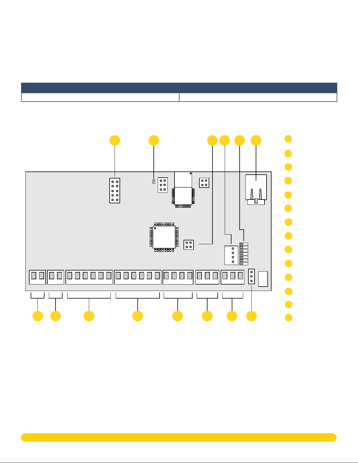
X1 Door Controller PCB Components
Refer to the diagram below throughout the installation�
Cell Module Header
A
B
C
D
F
E
A
B
Wi-Fi LED
C
R and L Terminal
XD Header
D
Operation LEDs
E
+AC/DC- +B AT- R1 W1 G1
G
H
B1 LC BC
I
R2 W2 G2
B2 LC BC
J
R
L
DS RX CI G 01 02 12V NC C NO
K
L
M
PWR/BOOT
READER 1
READER 2
RELAY
DATA
FIRE
LOCKDOWN
N
Ethernet Port
F
Power
G
H
Battery
In Reader
I
Out Reader
J
Inputs
K
Auxiliary Outputs
L
Door Relay
M
Wet/Dry Jumper
N
X1-8 INSTALLATION & PROGRAMMING GUIDE | DIGITAL MONITORING PRODUCTS 1
Page 4
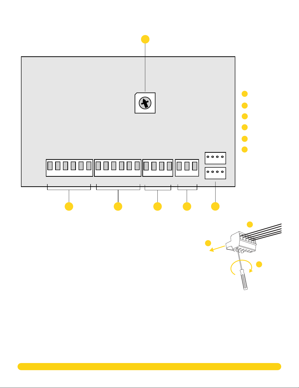
XD Module PCB Components
Refer to the diagram below throughout the installation�
A
3
3
2
2
1
1
0
0
9
9
7
8
7
8
Address Rotary
4
4
5
5
6
6
A
B
In Reader
Out Reader
C
Inputs
D
Door Relay
E
F
X1 and XD Headers
R1 W1 G1
B1 LC BC
B
R2 W2 G2
B2 LC BC
C
DS RX CI G NC C NO
D
E
Door Controller Plug‑In Terminals
Wiring terminals on an X1 Series system is done easily by using the plug-in
terminals�
1� Insert the wire into the slot�
2� Tighten the screw on the bottom�
3� Snap the plug-in terminal onto the Door Controller board�
3
F
Plug In
1
Insert
2
Tighten
X1-8 INSTALLATION & PROGRAMMING GUIDE | DIGITAL MONITORING PRODUCTS 2
Page 5
MOUNT THE SYSTEM
The metal enclosure for the X1 Series must be mounted directly to a wall, backboard, or other flat surface in
a secure, dry place to protect the system from damage� Do not remove the PCBs from the enclosure�
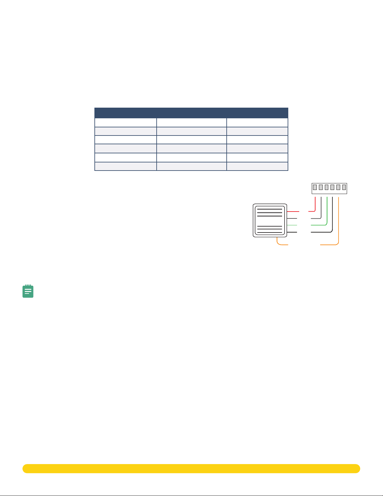
CONNECT A CARD READER
The X1 Series provides connections for 2 readers� The first reader is designated for the In Reader and the
second is designated for the Out Reader�
The X1 Series system also provides direct 12 VDC output to the reader on the RED terminal connection�
Terminal Name Wiegand Function OSDP Function
R1 & R2 12V+ DC +
W1 & W2 Data 1 B (485 +)
G1 & G2 Data 0 A (485 -)
B1 & B2 12V- (ground) DC -
LC LED Control N/A
BC Wiegand Buzzer Control N/A
Connect a Wiegand Card Reader
1� Connect the red wire (12 VDC) to terminal R1�
Reader 1 Terminals
R1 W1 G1
B1 LC BC
2� Connect the white wire (Data One) to W1�
3� Connect the green wire (Data Zero) to G1, black (ground) to B1�
4� Connect the orange or brown wire to LC�
Connect an OSDP Card Reader
1� For data transmission, connect the A wire (485 –) to the G1
Card Reader
Red
White
Green
Black
Orange/Brown
(Wiegand LED)
terminal and the B wire (485 +) to the W1 terminal�
2� For reader power, connect the red wire (DC + ) to the R1 terminal and the black wire (DC –) to the B1
terminal�
Note: The wire colors may be different depending on the reader being installed� Refer to the literature
provided with the reader for wire coding, wire distance, cable type (such as shielded), and other
specifications� The figure above shows the DMP-preferred wiring�
Optional Second Card Reader
For an out reader, connect the red, white, green, and black wires to the Reader 2 terminals: R2, W2, G2, and
B2� Connect the orange/brown wire to LC�
If using only one reader, it must be connected to reader 1�
X1-8 INSTALLATION & PROGRAMMING GUIDE | DIGITAL MONITORING PRODUCTS 3
Page 6
WIRE THE INPUTS
Door Switch (DS)
Connect a door contact or door position switch to indicate the status
of the door, whether it is open or closed� Use this terminal if enabling
door prop or door force�
This terminal is a Normally Closed input�
Request to Exit (RX)
Connect a motion sensing device or a mechanical switch to provide
RX capability to the system� RX can be used to activate the door
relay� When activated the RX activates the door lock relay based on
the programmed unlock time� Use this terminal if enabling forced
door�
This terminal is a Normally Open input�
DS RX
CI
G
Custom Input (CI)
+AC/DC- + BAT- R1 W1 G1
B1 LC BC
R2 W2 G2
B2 LC BC
This input triggers a rule through Dealer Admin� This could be a
button on a front desk for a receptionist to release a front door�
This terminal is a Normally Open input that is also used for a fire
alarm input if programmed�
Ground (G)
This terminal is the ground for the inputs�
WIRE THE OUTPUTS (DOOR CONTROLLER ONLY)
Use these switches to ground outputs for local outputs or door alarms
such as sounders, lights, or sirens� These are 12 VDC outputs� For
example, a sounder could be wired for local indication of a door prop
or door force event�
Aux Output 1 & 2 (O1 & O2)
Attach the negative wire of the device here�
The relay contacts must be connected to devices located within 98�5 ft
(30m) of the Door Controller�
12V+ (12V)
Attach the positive wire of the device here�
+AC/DC- +B AT- R1 W1 G1
01 02 12V
R2 W2 G2
B1 LC BC
B2 LC BC
DS RXCIG0102
DS RX CI G 01 02 12V NC C NO
12V NC C
NO
X1-8 INSTALLATION & PROGRAMMING GUIDE | DIGITAL MONITORING PRODUCTS 4
Page 7

WIRE THE ELECTRONIC LOCK
Power Supply positive
Jumper set
Form C Relay
The X1 Series system provides a Form C (SPDT) relay for controlling locks and other electronically-controlled
barriers� The three relay terminals marked NO C NC allow you to connect the device wiring to the relay for
module control�
The Form C relay draws up to 35 mA of current and contacts are rated for 1 Amp (resistive) at 12 VDC� When
connecting multiple locks to the Form C relay, the total current for all locks cannot exceed 1 Amp� If the total
current for all locks exceeds 1 Amp, problems will arise, it will not work as intended, and an isolation relay will
be required�
Diode
Connect the included diode as close to the magnetic lock or door strike as
possible to prevent inductive kickback� Observe polarity when connecting the
diode�
+
Positive
Wet/Dry Jumper
Putting the jumper on the top two terminals will place it in the dry condition and putting the jumper on the
bottom two terminals will place it in the wet condition� When using a dry relay, a power supply is needed to
power the lock/strike� When using a wet relay power is already supplied through the relay�
The X1-8 system is powered by the 505-12 Power Supply and is set up from the factory to utilize this power
supply to power the locks�
-
Negative
The Modules only wire dry because they do not have wet/dry jumpers�
Magnetic Lock - Normally Closed and Dry
DRY
Jumper set
WET
NC
Magnetic Lock positive
to Terminal NC
Diode
NO
C
to Terminal C
to Dry
Door Strike - Normally Open and Dry
Power Supply positive
to Terminal C
–+
Magnetic Lock
Magnetic Lock negative to
Power Supply negative
Magnetic Lock - Normally Closed and Wet
Reader 2
R2
W2
G2 LC
BC
B2
Magnetic Lock positive
to Terminal NC
Diode
Magnetic Lock
Power Supply
NC
C
–+
DRY
WET
NO
Jumper set
to Wet
Power Supply
Door Strike - Normally Open and Wet
Reader 2
R2
W2
G2 LC
B2
Door Strike positive
NC
NO
C
Door Strike negative to
Power Supply negative
BC
to Terminal NO
Diode
DC Door Strike
DRY
Jumper set
WET
to Dry
Door Strike positive
to Terminal NO
Diode
–+
DC Door Strike
DRY
WET
NC
NO
C
to Wet
–+
Magnetic Lock negative to
X1 terminal B2
X1-8 INSTALLATION & PROGRAMMING GUIDE | DIGITAL MONITORING PRODUCTS 5
Door Strike negative to
X1 terminal B2
Page 8

DETERMINE COMMUNICATION
The options in this section are in the DMP-recommended installation order� If an option is not part of your
desired application, move to the next option�
Ethernet Connection
Connect an Ethernet cable from the LAN/WAN connection to the X1 PCB
Ethernet port�
Two LEDs are located on the Ethernet port�
• The green LED indicates data is being sent over the network�
• The yellow LED indicates the speed of the transmission� A solid yellow
LED indicates the network is connected at 100BASE-T� A flashing
yellow LED indicates the network is connected at 10BASE-T�
Cellular Connection (Optional)
If the network cable or Wi-Fi are not connected, cell will be the primary communication� If the network cable
or Wi-Fi are connected, the cell will be the backup communication�
1� Attach the included standoff to the Door Controller�
2� Plug the Cell Module onto the standoff�
3� Plug the Cell Module into the Cell Header�
4� Attach the Cell Module Antenna cable to the antenna connector�
Ethernet Port
5� Run the cable around the 505-12 Power Supply�
6� Attach the antenna with the nut on the inside of the enclosure and the washers on the inside and the
top of the enclosure�
Cell Antenna
Nut and Washer
1
Stando
Door Controller
Header
2
Cell Module
Stando
Header
Door Controller
X1-8 Enclosure
3
4
Controller
Door
Cell
Antenna
Cable
Cell
Module
5
6
505-12 Power Supply
Cell Antenna Wire
Wi‑Fi Connection
A Wi-Fi connection or a static IP address must be established after
power up� See Wi-Fi instructions later in this guide�
Note: You can connect over Ethernet or Wi-Fi, but not both at
the same time�
Wi‑Fi Antenna
The yellow Wi-Fi antenna connects to the right of the cell antenna
on the enclosure�
X1-8 Enclosure
505-12 Power Supply
Wi-Fi Antenna
Nut and Washer
inside Enclosure
1� If the cable has become detached from the Door Controller,
simply wire it back onto the Wi-Fi module and run the cable
around the module�
2� Run the Wi-Fi cable around the 505-12 Power Supply and use
the included nut and washer to connect the antenna to the top
of the enclosure�
X1-8 INSTALLATION & PROGRAMMING GUIDE | DIGITAL MONITORING PRODUCTS 6
Page 9

APPLY POWER
Warning: Refer to your local state regulations before connecting to building power� Wiring methods
shall be in accordance with NEC, NFPA72, ANSI, and with all Authority Having Jurisdiction
Ground the System
Be sure to secure the green wire lead
to an earth ground� Connect to a
cold water pipe or ground rod when
available� Connection to an electrical
ground or conduit can also be used�
Gas pipes or sprinkler pipes should not
be used�
Wire AC Power
Connect an unswitched 120 V AC
60Hz power source to the transformer�
Knockouts are supplied for power
input�
Wire the Battery
The battery leads for the X1-8 come
pre-wired�
Connect the red battery lead to the
battery positive terminal� Connect
the black battery lead to the negative
battery terminal� Observe polarity
when connecting the battery� For
additional power, use the 318 Battery
Harness with additional batteries wired
in parallel�
Input:
120 VAC 60 Hz 1.5
Amps Unswitched
To AC
To Earth Ground
Attach ground wire
to an enclosure mounting hole
Black
White
Green
100 VAC Wire-In
Transformer
Output
16 VDC @ 100 VA
Violet
Module 1:
Address 2, Door 2
3
3
2
2
4
4
1
1
5
5
0
0
6
9
6
9
7
8
7
8
Module 2:
Address 3, Door 3
3
3
2
2
4
4
1
1
5
5
0
0
6
9
6
7
9
8
7
8
Gray
Battery Wires
BAT
+
Red
-
to Battery
+
-
+AC/DC-
Model 505-12
Black
Door Controller:
Door 1
Module 7:
Address 8, Door 8
3
3
2
2
4
4
1
1
5
5
0
0
6
6
9
9
7
8
7
8
DC
12 VDC @ 5 Amps
To X1 power
+
-
Wire the Modules
The modules come pre-wired and
addressed in the order shown here�
Module 3:
Address 4, Door 4
3
3
2
2
4
4
1
1
5
5
0
0
6
9
6
9
7
8
7
8
Module 4:
Address 5, Door 5
3
3
2
2
4
4
1
1
5
5
0
0
6
6
9
9
7
8
7
8
Module 6:
Address 7, Door 7
3
3
2
2
4
4
1
1
5
5
0
0
6
6
9
9
7
8
7
8
Module 5:
Address 6, Door 6
3
2
3
4
2
4
1
1
5
5
0
0
6
6
9
9
7
8
7
8
X1-8 INSTALLATION & PROGRAMMING GUIDE | DIGITAL MONITORING PRODUCTS 7
Page 10

Check the Addresses of the Modules
The Module address is based on its location in the enclosure�
XD 1 - Address 2
3
2
4
1
5
0
6
9
8
7
3
2
4
1
5
0
6
9
7
8
X1 - Pre-Addressed
to Address 1
R1 W1 G1
3
2
4
1
5
0
6
9
8
7
R1 W1 G1
3
2
4
1
5
0
6
9
8
7
R2 W2 G2
B1 LC BC
B2 LC BC
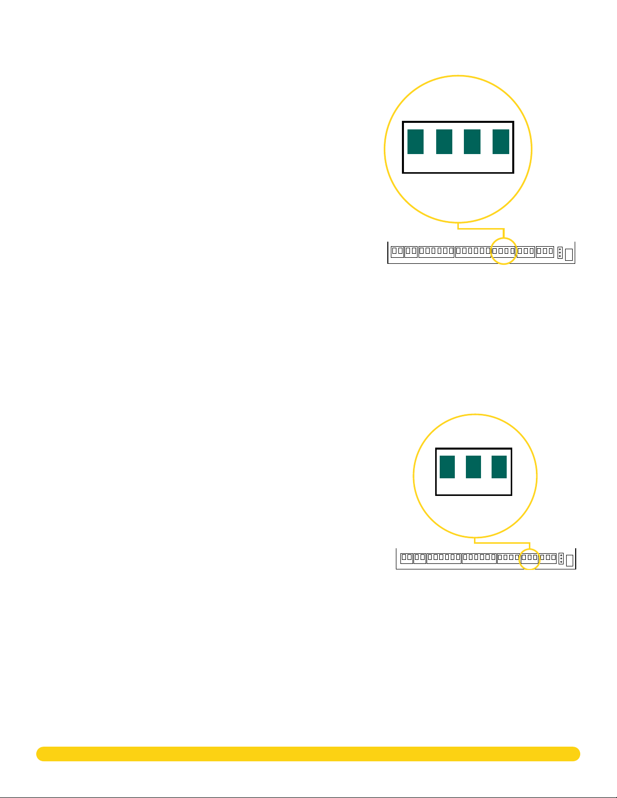
DS RX CI G NC C NO
XD 2 - Address 3
3
2
4
1
5
0
6
9
7
8
R2 W2 G2
B1 LC BC
B2 LC BC
DS RX CI G
NC C NO
XD 3 - Address 4
3
2
4
1
5
0
6
9
7
8
XD 7 - Address 8
3
2
4
1
0
6
9
7
8
R1 W1 G1
B1 LC BC
R2 W2 G2
B2 LC BC
DS RX CI G
XD 6 - Address 7
3
2
4
1
0
9
7
8
3
2
4
5
NC C NO
5
6
1
5
0
6
9
8
7
3
2
4
1
5
0
6
9
8
7
R1 W1 G1
B1 LC BC
R2 W2 G2
B2 LC BC
DS RX CI G
NC C NO
R1 W1 G1
B1 LC BC
R2 W2 G2
B2 LC BC
DS RX CI G
NC C NO
XD 4 - Address 5 XD 5 - Address 6
3
2
4
1
5
0
6
9
8
7
R1 W1 G1
B1 LC BC
R2 W2 G2
B2 LC BC
3
2
4
1
5
0
6
9
7
8
DS RX CI G
NC C NO
R1 W1 G1
B1 LC BC
R2 W2 G2
B2 LC BC
3
2
4
1
5
0
6
9
7
8
DS RX CI G
NC C NO
X1-8 INSTALLATION & PROGRAMMING GUIDE | DIGITAL MONITORING PRODUCTS 8
3
2
4
1
5
0
6
9
8
7
Page 11

Door Controller Wiring Example
The diagram here shows the transformer and the battery wiring� It also shows a possible application with an
electronic lock wired normally closed with wet contacts�
To 505-12 Power Supply
+
Red
Card Reader
Door
Contact
-
+AC/DC- +B AT- R1 W1 G1
B1 LC BC
R2 W2 G2
DSRXCIG01 02 12V NC C
BC
B2 LC
DRY WET
NO
Jumper Set to Wet
White
Green
Orange/Brown
(Wiegand LED)
Black
Red
+
-
Second
Card Reader
Optional
NC
Magnetic Lock
B2
12V
O2
–+
AUX
Output 2
12 V Battery
12V
O1
DS
G
AUX
Output 1
Request
to Exit
XX = wire polarity or terminal location
X1-8 INSTALLATION & PROGRAMMING GUIDE | DIGITAL MONITORING PRODUCTS 9
RX
G
Custom
Input
CI
G
Page 12

Module Wiring Example
A module wires similarly to a Door Controller, except the module locks must be wired in a dry state with
power supplied by the built-in 505-12 5 Amp Power Supply�
Wiring from Previous X1/XD
3
2
4
1
5
0
6
9
8
7
Red
White
Orange/Brown
(Wiegand LED)
Card Reader
Door
Contact
XX = wire polarity or terminal location
Green
Request
to Exit
Black
DS
12VDC
R1 W1 G1
B1 LC BC
R2 W2 G2
B2 LC BC
DS RX CI G NC C NO
C
12/24 VDC
Optional
Second
NC
Power Supply
Card Reader
-
–+
Magnetic Lock
G
RX
G
Custom
Input
CI
G
X1-8 INSTALLATION & PROGRAMMING GUIDE | DIGITAL MONITORING PRODUCTS 10
Page 13

CONNECTION SETTINGS
If not connecting over Ethernet, connect to Wi-Fi at this time� If connecting over Ethernet, skip to Configure
Network Settings�
Configure Wi‑Fi Settings
On power up, the X1 broadcasts an SSID of DMPX1 followed by the system’s serial number� No password is
required to connect to the SSID�
The Wi-Fi LED blinks during the broadcast�
1� Connect to the X1 SSID using a device capable of launching a browser (cell phone, laptop, etc�)�
Note: If using a phone, use only Wi-Fi and disable mobile data� Some phones will try to use the
mobile data connection if the Wi-Fi does not have an internet connection�
2� Enter 192�168�1�1 into the URL field� The Wi-Fi LED will blink�
3� In the Wi‑Fi options, enter the customer's Wi-Fi network information�
4� Select Apply, and the X1 will reset�
4
3
Once the X1 has reset it will automatically connect to the customer's
network with the updated settings�
Wi-Fi LED
L Terminal
Note: If fifteen minutes have passed since power up or the X1 does
not broadcast an SSID, short the L terminals for 3 seconds and then
place the jumper back on one pin of the L terminal� This will give an
additional fifteen minutes of broadcasting�
Configure Network Settings
1� Connect to the X1 SSID using a device capable of launching a
browser (cell phone, laptop, etc�)�
Note: If using a phone, use only Wi-Fi and disable mobile
R
L
data� Some phones will try to use the mobile data connection
if the Wi-Fi does not have an internet connection�
2� Enter 192�168�1�1 into the URL field�
3� In the DHCP options, make edits to the desired fields�
• DHCP: This option is toggled on as default�
• Static IP: Toggle o DHCP and enter the information in the required fields�
4� Select Apply, and the X1 will reset�
Configure Cell Settings
On power up, if using cell, the X1 automatically connects and programming in Dealer Admin can begin�
R
L
X1-8 INSTALLATION & PROGRAMMING GUIDE | DIGITAL MONITORING PRODUCTS 11
Page 14

PROGRAM IN DEALER ADMIN
After you’ve installed the X1 Series Door Controller and configured basic communication settings, follow the
steps in each of the following sections to program a system in Dealer Admin:
1� Sign In to Dealer Admin
2� Add a Customer
3� Add a System
4� Add the X1
5� Add Card Formats
6� Enable Video Services
7� Add an App User
8� Log in as Customer
Sign In to Dealer Admin
1
Go to the Dealer Admin login page� Enter your Email and Password, then press Sign In�
Add a Customer
2
1� At Customers, press the Add icon �
2� Enter the customer’s name and email�
3� Enter the customer’s contact information if desired�
4� Press Save�
Add a System
3
Before you can add a door controller or program doors, you must add a system in Dealer Admin�
1� Go to Customers�
2� Select a customer to open the Customer Summary�
3� In Systems, press the Add icon �
4� Enter a name for the system�
5� In System Type, select X1�
6� Configure billing address and time options as needed�
7� Enter the door controller’s serial number�
8� Press Save�
X1-8 INSTALLATION & PROGRAMMING GUIDE | DIGITAL MONITORING PRODUCTS 12
Page 15

Add an X1
4
If door options don’t open automatically, select the X1 that you want to configure�
1� Enter a descriptive name for the door�
2� In Strike Time, enter the number of seconds that you want the door to unlock when access is
granted�
3� In Strike Delay, enter the number of minutes that you want to delay the door unlock when
access is granted�
4� In Reader Protocol, choose a protocol for this door’s readers: Wiegand or OSDP� For OSDP
readers, configure buzzer and LED options�
Note: OSDP readers must be either new or factory reset so they can bind properly with
the system� A unique OSDP secure key is automatically programmed�
5� In Authorization, choose which authorization type can be used to access any of the doors�
Additional Door Options:
• Buzzer (OSDP) allows the reader to beep when a card is read�
• LED (OSDP) allows the reader LED to turn on and operate the same as a Wiegand reader LED, lighting green when
the module relay activates� If disabled, the reader LED is turned o and does not operate in any condition�
• Card (Authorization) enables the use of cards for any of the doors�
• Card + PIN (Authorization) enables the use of cards or card + PIN for any of the doors�
• Dual Authority (Authorization) enables the use of cards or dual authority for any of the doors�
• Fire Zone indicates this custom output triggers with a fire alarm�
• Fire Exit allows the door to unlock during a fire so people can exit the area�
• Include in Lockdown allows this door to be included when a lockdown is initiated�
• Door Sensor allows a door contact to monitor door sensor�
• In Prop Time, enter the number of seconds that you want to allow the door to remain open without triggering an
alert�
• Door Forced Message sends a status message any time a door is forced open�
• Request to Exit (REX) allows a REX device to shunt the door sensor to prevent door force messages when people
exit� REX is usually triggered by motion near the door or a button press�
• Unlock On REX appears when the Request To Exit toggle is switched on� The toggle defaults to switched on� To allow
the door to unlock when a Request to Exit input is received, switch on the feature� This is typically for magnetic locks�
To keep the door locked when a Request to Exit input is received, switch o the toggle� This is typically for door
strikes�
6� Turn on additional options as needed�
7� Press Save�
Add Card Formats
5
The first card format for any door is defaulted to DMP� Refer to Card Format Options below when
programming card formats�
1� In Card Formats, press the Add icon �
2� Give the card format a name�
3� Select a card format and configure format settings�
Card Format Options�
• DMP (card format) use cards with DMP’s format with a 26 – 45 bit data string�
• Custom (card format) use cards with a custom bit length and configuration�
• Any (card format) unlock the door with any valid card read�
• Wiegand Length is the total number of bits to be received in Wiegand code including parity bits�
• Site Code Position is the site code start position in the data string�
• Site Code Length is the site code length�
• User Code Position defines the user code start bit position�
• User Code Length defines the credential user code length�
• User Code Digits defines the user code length�
• Require Site Code restricts the door so it only unlocks when the card’s site code matches one programmed in Site Code�
4� Press Save�
X1-8 INSTALLATION & PROGRAMMING GUIDE | DIGITAL MONITORING PRODUCTS 13
Page 16

Enable Video Services
6
1� In Video Services, press the Add icon �
2� Select the types of cameras or NVRs that you want to enable on the system�
3� Select any third-party applications that you want to enable on the system� This allows users
to sign in to their services from Virtual Keypad�
4� Press Save�
5� Back on the System Information page, select the number of cameras and storage space you
require or choose the number of doorbells that you want to add to the system�
Add an App User
7
Adding an app user to an X1 system automatically adds them as a user in Virtual Keypad�
1� Go to Customers�
2� Select a customer to open the Customer Summary�
3� In the App Users section, press the Add icon �
4� For a user that doesn’t have a Virtual Keypad account, select New� For a user that already has
an account, select Existing�
5� For a new user, enter their email address� For an existing user, start typing to search for their
email and select it from the list�
6� Set the user’s authority level to either Administrator to manage multiple systems or Standard
to manage a single system�
7� For a new user, enter their first and last name� If you don’t want to generate a random
password for the user, clear Create Random Password then manually enter one�
8� If you want to email the user video clips, select Email Video Clips�
9� Select systems and permissions for the user�
10� Press Save�
Note: If you receive a message that states the email is already in use, the user already has a
Virtual Keypad account� Select Existing below the user’s email address�
Log In as a Customer
8
To log in to Virtual Keypad and view the system like a customer would, press Login as Customer�
This adds you to the system as a temporary app user with admin privileges without the capability
to view video� Your temporary app user expires and is automatically removed from the system after
1 hour�
X1-8 INSTALLATION & PROGRAMMING GUIDE | DIGITAL MONITORING PRODUCTS 14
Page 17

TEST THE SYSTEM
Make sure that the Reader LED(s) is on and the Door Controller’s Power LED is on� If connected to Wi-Fi,
the Wi-Fi LED is on solid� If connected to network, the Network Port light is blinking� For cell and all
communication methods, check that Door Controller is communicating with Dealer Admin and Virtual
Keypad after Dealer Admin programming is completed�
ADDITIONAL INFORMATION
LEDs
LED Meaning
PWR/BOOT On when board is powered and operating
READER 1 Turns on for one second to indicate receipt of a valid input from the In Reader determined by card
format programming
READER 2 Turns on for one second to indicate receipt of a valid input from the Out Reader determined by card
format programming
RELAY On when door relay is active
DATA On when the Modules are connected and communicating properly
FIRE On when the Door Controller is in a fire alarm
LOCKDOWN On when The Door Controller is in a lockdown state
Cell Module Removal
1� Unscrew the antenna cable from the antenna connector�
2� Unplug the Cell Module from the Cell Header�
3� Pinch the tab of the standoff to release the module from the
Door Controller�
Tab
X1-8 INSTALLATION & PROGRAMMING GUIDE | DIGITAL MONITORING PRODUCTS 15
Page 18

FCC INFORMATION
This device complies with Part 15 of the FCC Rules� Operation is subject to the following two conditions:
1� This device may not cause harmful interference, and
2� this device must accept any interference received, including interference that may cause undesired operation�
The antenna used for this transmitter must be installed to provide a separation distance of at least 20 cm (7�874 in�) from all persons� It must not be located
or operated in conjunction with any other antenna or transmitter�
Changes or modifications made by the user and not expressly approved by the party responsible for compliance could void the user’s authority to operate
the equipment�
Note: This equipment has been tested and found to comply with the limits for a Class B digital device, pursuant to part 15 of the FCC Rules� These
limits are designed to provide reasonable protection against harmful interference in a residential installation� This equipment generates, uses and
can radiate radio frequency energy and, if not installed and used in accordance with the instructions, may cause harmful interference to radio
communications� However, there is no guarantee that interference will not occur in a particular installation� If this equipment does cause harmful
interference to radio or television reception, which can be determined by turning the equipment off and on, the user is encouraged to try to correct
the interference by one or more of the following measures:
1� Reorient or relocate the receiving antenna�
2� Increase the separation between the equipment and receiver�
3� Connect the equipment into an outlet on a circuit different from that to which the receiver is connected�
4� Consult the dealer or an experienced radio/TV technician for help�
INDUSTRY CANADA INFORMATION
This device complies with Industry Canada Licence-exempt RSS standards� Operation is subject to the following two conditions:
1� This device may not cause interference, and
2� this device must accept any interference, including interference that may cause undesired operation of the device�
This system has been evaluated for RF Exposure per RSS-102 and is in compliance with the limits specified by Health Canada Safety Code 6� The system
must be installed at a minimum separation distance from the antenna to a general bystander of 7�87 inches (20 cm) to maintain compliance with the
General Population limits�
Le présent appareil est conforme aux CNR d’Industrie Canada applicables aux appareils radio exempts de licence. L’exploitation est autorisée aux deux
conditions suivantes:
1� l’appareil ne doit pas produire de brouillage, et
2� l’utilisateur de l’appareil doit accepter tout brouillage radioélectrique subi, même si le brouillage est susceptible d’en compromettre le
fonctionnement.
L’exposition aux radiofréquences de ce système a été évaluée selon la norme RSS‑102 et est jugée conforme aux limites établies par le Code de sécurité 6
de Santé Canada. Le système doit être installé à une distance minimale de 7.87 pouces (20 cm) séparant l’antenne d’une personne présente en conformité
avec les limites permises d’exposition du grand public.
X1-8 DOOR CONTROLLER
Specifications
Power
Input 120 V AC
Current Draw 166 mA at 12 V DC
X1 96 mA
XD 10 mA
Battery 2 x 9 Ah (recommended)
2 x 12 Ah (max)
Power Output Max*
505-12 5 A
X1 1.5 A
XD 750 mA
O1, O2 Max 50 mA
* The 505-12 is factory-wired to supply power to all included
modules. If door hardware exceeds 5 A an additional power supply
will be required.
Communication Options
Ethernet
Wi-Fi
Cellular 263LTE-A-X1/381-2,
263LTE-V-X1/381-2
Designed, engineered,
and manufactured in
Springfield, Missouri
Mechanical
Enclosure Dimensions 14.5” W x 32” H x 4” D
(lid adds 0.5" on each side)
36.8 cm W x 81.3 cm H x 10.2 cm D
(lid adds 1.3 cm on each side)
Weight 34 lbs
Environmental
Temperature 0 ° C to 49 ° C
32 ° F to 120 ° F
Humidity 85%
Compatibility
263LTE-A-X1/381-2 (X1-8) Cell Module for AT&T
263LTE-V-X1/381-2 (X1-8) Cell Module for Verizon
X1-8PCB X1-8 PCB Replacement
XDPCB XD PCB Replacement
Certifications
ANSI/UL 294 Access Control System Units
Level I Destructive Attack and Line Security
Level IV Endurance and Standby Power
Manufacturer’s Limited Warranty
3 Year warranty against defects in materials and
workmanship. Visit DMP.com for full details.
INTRUSION • FIRE • ACCESS • NETWORKS
2500 North Partnership Boulevard
Springfield, Missouri 65803-8877
800.641.4282 | dmp.com
 Loading...