

Page 1
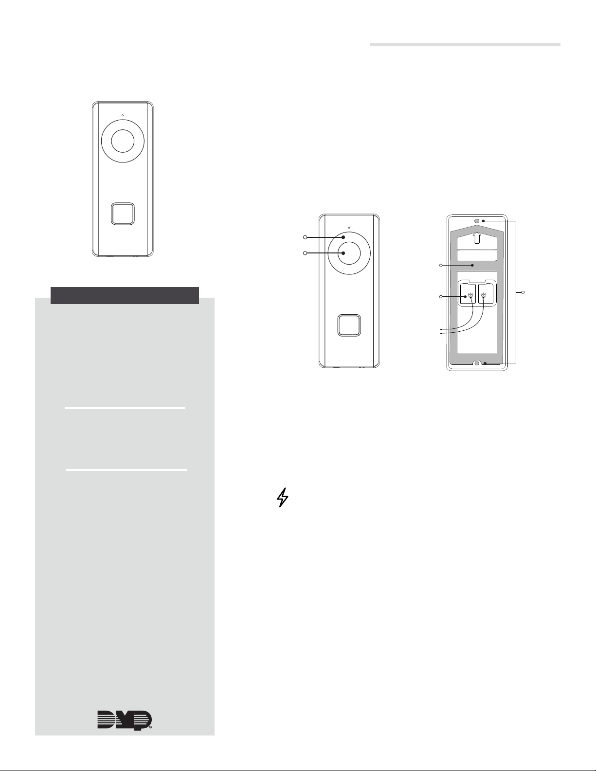
V-4060DB VIDEO DOORBELL
Wires
Rubber
Gasket
Mounting
Holes
IR Light
Installation Guide
Figure 1: V-4060DB
DESCRIPTION
The V-4060DB is a 2.4 GHz Wi-Fi
enabled video doorbell capable
of of recording and storing video
clips that are viewable on the Virtual
KeypadTM App.
The V-4060DB provides 16 GB of
storage on a pre-installed SD card
for local recording.
1
PREPARING VIDEO DOORBELL FOR
INSTALLATION
1. Remove the clear plastic film on the lens of the camera and
and the clear plastic film on the IR light referenced in Figure 2.
2. Remove the doorbell faceplate.
3. Place the rubber gasket on the back of the doorbell as shown
in Figure 3.
4. Remove the screws on the rear panel of the doorbell. Place
the circular end of the provided power cables around the
screws and reconnect them to the doorbell.
Lens
Figure 2: Lens and IR Light
Location
Figure 3: Connecting the
Power Cables
Compatibility
• Virtual Keypad™ App 6.18 or
higher for iOS and Android
devices
What is Included?
• V-4060DB Video Doorbell
• Pre-installed 16 GB SD card
• Four dierent color faceplate
options
• Power Connector
• Hardware Pack
• Power Booster
2
INSTALLING THE VIDEO DOORBELL
Replacing Existing Doorbell
If you are replacing an existing doorbell, you must install the
included power kit to the existing mechanical chime. The power
kit ensures that the video doorbell receives the power it needs.
Caution: Turn o the breaker supplying power to the
mechanical chime and where the video doorbell will be
installed.
1. Remove the existing doorbell from the wall, leaving the
existing wiring exposed.
2. Remove the provided clear adhesive mounting template
from the yellow paper and align Hole A with the cable hole
on the wall. This is where the existing wiring will connect to
the new doorbell.
3. Drill through the two holes marked Hole 1 on the mounting
template. This ensures the doorbell can be installed
accurately. For wood installations, use a 1/16” drill bit. For
masonry installations, use a 7/32” drill bit. Use the included
white anchors if necessary.
4. Connect the exposed wiring to the video doorbell power
leads.
5. Mount the video doorbell body to the wall with the two
included long screws.
6. With the breaker supplying power to the mechanical chime
still o, remove the cover from the mechanical chime.
7. Loosen the screws on the provided plastic screw terminal.
Insert the red and black crimped ends of the wire and
tighten them down.
Page 2
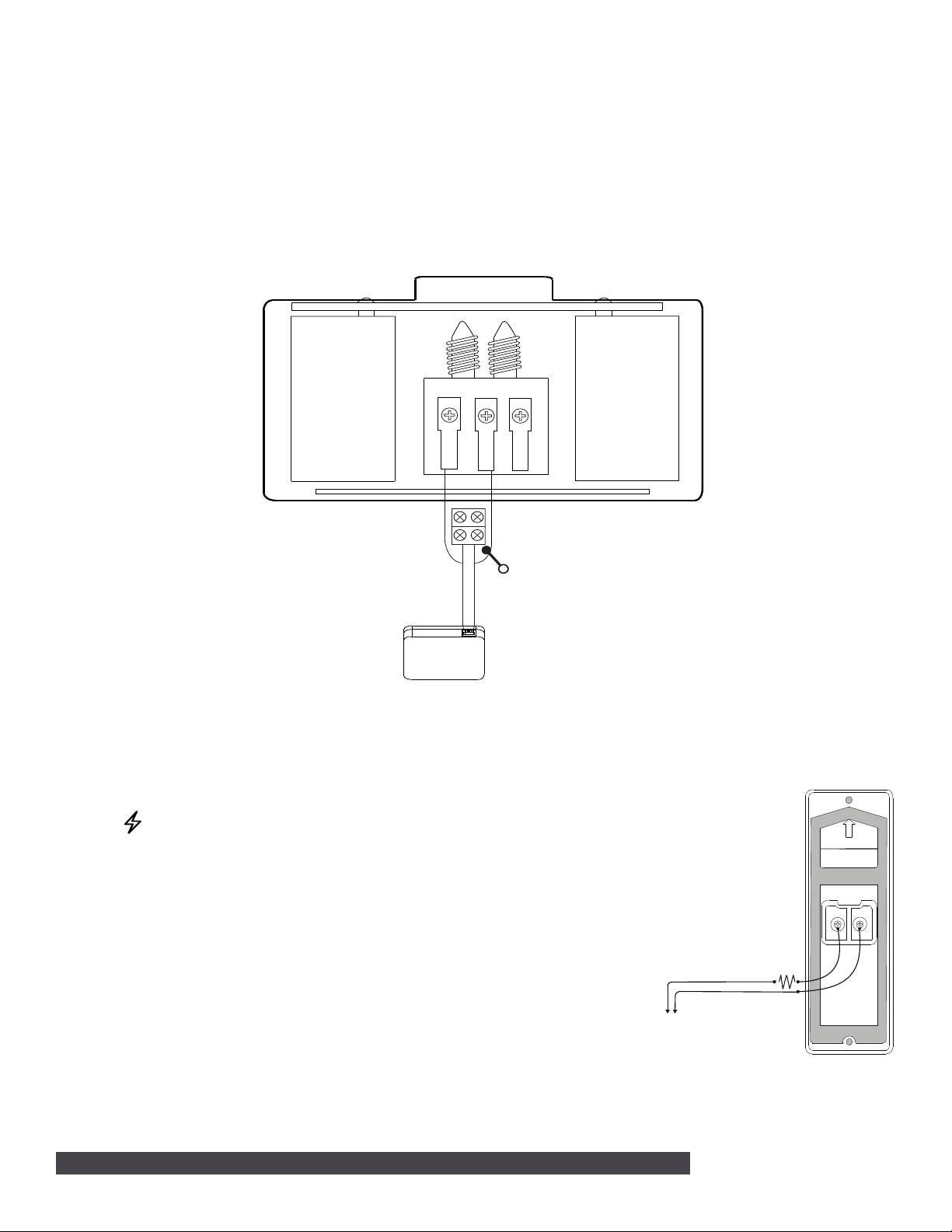
Resistor Connection
To In-Wall or Plug-In Transformer
Included Screw Terminal
Existing Chime
Front
Trans
Rear
Power Booster
Red WireBlack Wire
Replacing Existing Doorbell (Continued)
8. Insert the white connector end of the wires to the power booster.
9. Loosen the TRANS terminal on the mechanical chime and connect the short end of the red wire to it.
10. Loosen the FRONT terminal on the mechanical chime and connect the short end of the black wire to it.
11. Once the power kit has been installed, mount the screw terminal and power kit within the mechanical
chime housing using the adhesive backing and replace the cover.
12. Turn on the breaker to the part of the home where the video doorbell and mechanical chime are installed.
Failure to install the power kit may result in the following:
• Your chime sounds faint or makes a humming noise.
• Your doorbell reboots unexpectedly.
Figure 4: Installing the Power Kit
New Doorbell Installation
If you do not have an existing doorbell and plan on using a transformer (in-wall or plug-in) then you must
use the included resistor. The power must come from a low voltage
transformer with 16-24 VAC.
2 V-4060DB VIDEO DOORBELL | DIGITAL MONITORING PRODUCTS
Caution: Turn o the breaker supplying power to the area that the
video doorbell will be installed.
1. Place the adhesive mounting template where you want the
doorbell to be installed. Drill a hole through Hole A for wire
routing.
2. Drill through the two holes marked Hole 1 on the mounting
template. This ensures the doorbell can be installed accurately.
For wood installations, use a 1/16” drill bit. For masonry
installations, use a 7/32” drill bit. Use the included white anchors if
necessary.
3. Route the wires from the power source through the center hole
and connect the included resistor to one of the wires.
4. Connect the power leads from the video doorbell to the power
source.
5. Align the screw holes at the top and bottom of the doorbell with
Figure 5: Resistor Connection to in-wall
the drilled holes in the wall.
6. Mount the video doorbell to the wall with the two included long
screws.
7. Restore power to the part of the home where the video doorbell is installed.
or plug-in transformer
Page 3

Security Screw
3
4
SET UP DOORBELL IN DEALER ADMIN
1. Log into DMPDealerAdmin.com.
2. Select the appropriate system for the V-4060DB Video Doorbell.
3. On the System Information screen under Add-On Features, check the Video Doorbell box. This will
enable the doorbell to sync with the Virtual Keypad App.
CONNECT DOORBELL TO WI-FI USING VIRTUAL KEYPAD APP
The video doorbell requires a 2.4 GHz Wi-Fi signal. It does not support 5 GHz Wi-Fi.
1. Upon completing the power up sequence, the doorbell will announce it is ready to be configured. If
no action is taken within three minutes the video doorbell will exit Wi-Fi configuration mode. Reset
the video doorbell to restart Wi-Fi configuration. This can be done by pressing and holding the RESET
button located on the bottom left side of the video doorbell for 20 seconds. The doorbell will announce
when reset sequence is complete.
2. Log into the Virtual Keypad App and go to the Doorbell tab.
3. Tap Setup Doorbell.
4. Scan the QR code on the front of the video doorbell. Suggested scanning distance is 2-4 inches.
Note: If the device is not able to read the QR code, you will be given the option to retry scanning
the code or manual entry. If you select manual entry, enter the Serial Number and Verification Code
located on the front of the video doorbell.
5. Select Configure Wi-Fi.
6. Ensure your phone is connected to the Wi-Fi network the video doorbell will use. This allows the
doorbell to automatically inherit your Wi-Fi network. The Virtual Keypad App will prompt you to enter
the password for your Wi-Fi network. Press Continue.
7. A QR code then appears on your device screen. Hold the QR code in front of the doorbell. Suggested
scanning distance is 2-4 inches. The doorbell will produce a single audible beep once the QR code has
been read. Press Continue in the Virtual Keypad App after you hear the doorbell beep.
8. Give your doorbell a name and press Finish.
5
ATTACHING THE FACEPLATE
Whether replacing an existing doorbell or installing new doorbell, the faceplate for
the doorbell should be attached last.
1. After the doorbell has been connected to the Wi-Fi network, attach the
faceplate to the doorbell body.
2. Use the included short security screw to fix the faceplate to the doorbell.
See Figure 6.
Figure 6: Attaching the Faceplate
V-4060DB VIDEO DOORBELL | DIGITAL MONITORING PRODUCTS 3
Page 4

ADDITIONAL INFORMATION
REPLACING THE SD CARD (OPTIONAL)
Your doorbell comes with a 16 GB SD card pre-installed for storing video files. SD
cards larger than 16 GB can also be used. To install a dierent SD card, follow the
steps below.
1. Remove the faceplate attached on the doorbell to view the front panel and
side panel of the doorbell.
2. Remove the card slot cover. The slot cover is on the right side of the
doorbell with a vertical arrow on it.
3. Insert the new SD card into the card slot.
4. Place the slot cover back over the SD card and reattach the faceplate.
Note: Motion detection does not support recording without an SD card.
Figure 7: Installing the SD Card
CONNECTING THE DOORBELL TO AN NVR
After the doorbell has been set up in the Virtual Keypad App and after obtaining the IP address that your router has
assigned to the doorbell, follow the NVR manufacturer recommended steps to add a camera to an NVR.
1. Choose Manual mode to add a camera.
2. Enter the IP address.
3. Set the protocol to ONVIF.
4. Leave the Management Port at the default 8000, the Channel Port as the default 1, and the TransferProtocol as
the default Auto.
5. The username is “admin”. The password is a combination of the word “admin” followed by the verification
code that is on the label of the doorbell located under the cover below the serial number. As an example, if the
verification code is ILGWQM then the password would be adminILGWQM.
SD Card
CHANGING SSID OR PASSWORD
1. Delete the doorbell from the Virtual Keypad App.
2. Remove the doorbell’s cover and hold down the reset button for 25 seconds or until the doorbell audibly states,
“doorbell is rebooting.” The doorbell will go through its reboot process and announce when it is ready to be
reconfigured.
3. Repeat instructions in Replace Existing Doorbell.
V-4060DB VIDEO DOORBELL
Specifications
Sensor and Lens:
Image Sensor CMOS 2MP HD
Lens f1.96 mm, F 2.2
Field of View 180 degrees (Horizontal),
96 degrees (Vertical)
Video Compression H.264
Frame Rate Up to 30 frames per second
Wireless Compatibility 2.4 GHz
IR Distance 16 ft
Network:
Wireless Compatibility 2.4 GHz
Storage:
On-Board Storage 16 GB SD card installed
Hardware:
Power Required 16 VAC to 24 VAC
Power Consumption Max 0.6 A
Working Temperature -22 F to 122 F
Dimensions (LxWxH) 4.82” x 1.81” x 1.11”
Compatibility
Virtual Keypad App Version 6.18 or higher
Accessories
V-4060DB-VW
V-4060DB-HW Horizontal Wedge
V-4060DB-PK Power Kit
V-4060DB-SILVER/10 Cover plate - Silver 10 pack
V-4060DB-WHITE/10 Cover plate - White 10 pack
V-4060DB-BLACK/10 Cover plate - Black 10 pack
V-4060DB-CHAR/10 Cover plate - Charcoal 10 pack
321 Plug-In Transformer
Vertical Wedge
LT-1883 20134
© 2020
INTRUSION • FIRE • ACCESS • NETWORKS
2500 North Partnership Boulevard
Springfield, Missouri 65803-8877
800-641-4282 | DMP.com
 Loading...