

Page 1
INSTALLATION AND PROGRAMMING GUIDE
SR3
Bluetooth and Proximity Reader
Page 2

Page 3

CONTENTS
Get Started ..................................................1
Procedure ..................................................................... 1
What’s Included ......................................................... 1
What You’ll Need ...................................................... 1
Step 1: Install the Reader ......................... 2
Mount the Reader .................................................... 2
Wire the Reader ....................................................... 3
Attach the Cover ...................................................... 4
Step 2: Enroll & Associate the Reader ... 5
56-Bit Card Format ................................................. 5
Step 3: Purchase Credentials ..................6
Compatibility ............................................................13
Panels and Door Controllers ...........................13
Access Control Modules ...................................13
Keypads ..................................................................13
Apps .........................................................................13
125 kHz Proximity Credentials .......................13
Ordering Information ............................................13
Specifications ...........................................................14
Compliance Requirements ..................................14
Wiring and Power .............................................. 14
UL 294 .................................................................... 14
Step 4: Assign a Mobile Credential ........ 7
User Training Tips .................................................... 7
Step 5: Bind a Credential to a Device .... 8
Step 6: Use a Credential ..........................9
Reduce Notifications (Android) ......................... 9
Reference ..................................................10
Test the Reader ........................................................10
LED Operation .........................................................10
Troubleshooting .......................................................11
Reset the Reader ....................................................12
Certifications ............................................................14
Underwriters Laboratory (UL) Listed ......... 14
FCC Information ..................................................15
Industry Canada Information .........................15
FCC/IC RF Exposure Requirements ............15
Reset to Defaults ................................................12
Factory Reset .......................................................12
Page 4
GET STARTED
SR3 Bluetooth and Proximity Readers support Mobile Credentials and 125 kHz proximity credentials. The reader comes
with two mounting options, mullion or single-gang, and is suitable for indoor or outdoor use. The SR3 uses the Wiegand
reader protocol to communicate with door controllers or access control modules.
Procedure
The installation must follow this procedure:
Step 1 (Technician): Install the reader.
Step 2 (Technician): Enroll and associate the reader with a system in Tech APP.
Step 3 (Administrator): Purchase credentials for a customer in Dealer Admin.
Step 4 (Customer): Assign credentials to a user in Virtual Keypad.
Step 5 (End User): Bind a mobile credential to a user’s device in Virtual Keypad.
Step 6 (End User): Use the credential at the SR3 Bluetooth Reader.
This guide walks you through all 6 steps.
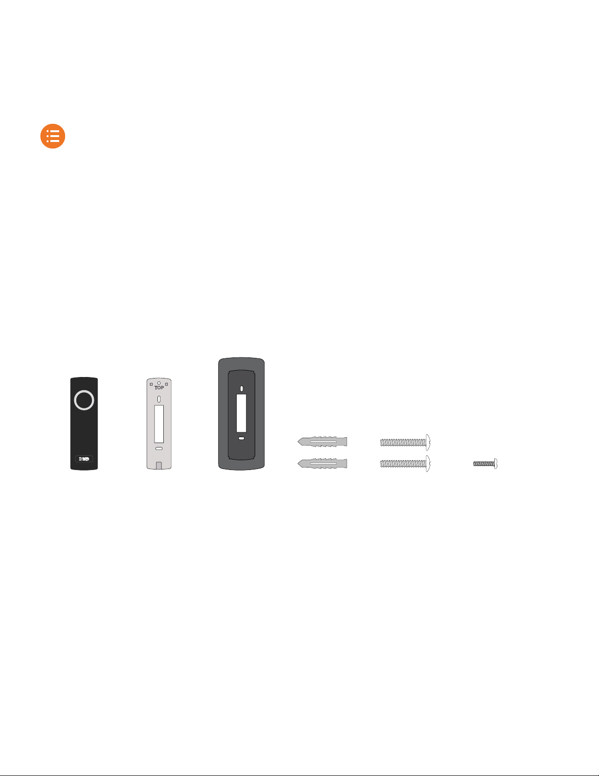
What’s Included
TOP
One
SR3 Bluetooth
Reader
One
Mullion
Base
One
Single-Gang
Mounting Plate
What You’ll Need
▶ Drill
▶ If mounting with wall anchors, a 5/16” (8.0 mm) drill bit
▶ If mounting without wall anchors, a 5/64” (2.0 mm) drill bit
Two
Wall
Anchors
Two
Mounting
Screws
(#6 x 1”)
One
Case
Screw
(#4 x 1/2”)
▶ #1 Phillips screwdriver
▶ #2 Phillips screwdriver
▶ Pliers
▶ Wire connectors
▶ Electrical tape
SR3 Installation and Programming Guide | Digital Monitoring Products 1
Page 5
STEP 1: INSTALL THE READER
This section covers the steps required for a technician to physically install the reader including mounting, wiring, and
attaching the cover.
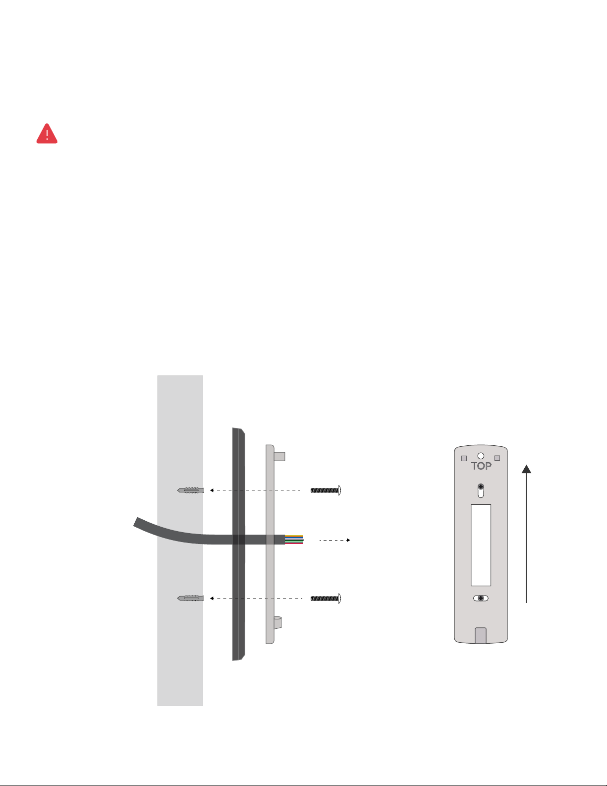
Mount the Reader
WARNING: Do not press and hold the button on the back of the reader. This procedure clears the unit’s memory
and firmware, which renders the device inoperable until it is reconfigured and re-enrolled.
Never mount the reader directly on a moving surface such as a door or gate. Isolate the reader from repetitive shocks
and potential damage. The reader can be mounted on a wall or any suitable flat surface.
1. Determine the purpose of each wire before removing an existing reader. Use a voltage meter to verify that 12VDC
is supplied by the controller, then disconnect power from the reader’s power source
2. Pull the existing wires through the wall. Use the reader base to mark locations for the mounting holes on the
surface. Do not use the plastic base as a guide when drilling.
3. Move any wires in the drill’s path. Drill holes in the surface no more than 1 inch deep. If using wall anchors, insert
them into the holes you drilled in the mounting surface.
4. Slide the base over the existing wiring. If using the single-gang bracket, slide the bracket on first, then the reader
base. Ensure the base side marked TOP is mounted up.
5. Use the included #6 screws to secure the mounting base to the surface. Do not overtighten the screws.
Wires from
Access Control
Module, Keypad,
or Door Controller
Mounting Surface
Wall
Anchor
(optional)
Wall
Anchor
(optional)
Single-Gang
Bracket
(optional)
Mount Base
with Side Marked
TOP Facing Up
TOP
Reader
Base
Mounting and Base Orientation
SR3 Installation and Programming Guide | Digital Monitoring Products 2
Page 6

PWR/BOOT
READER 1
READER 2
RELAY
DATA
FIRE
LOCKDOWN
Wire the Reader
Connect the reader wires to the access controller according to the purpose of each controller terminal. Refer
to Table 1 and the following examples for details. For wiring and power requirements, refer to “Wiring and Power”.
WIRE COLOR PURPOSE
TYPICAL X1 SERIES
TERMINALS
TYPICAL 734 SERIES
TERMINALS
TYPICAL KEYPAD
WIRES
Red Power (Positive) R1 1 (RED) Red
Black Ground (Negative) B1 4 (BLK) Black
White Data 1 W1 2 (WHT) White
Green Data 0 G1 3 (GRN) Green/White
Blue Green LED LC LC None
Orange Beeper BC RA None
Purple Red LED None None None
Yellow Smart Card Present None None None
Table 1: Wire Connections
X1 Series
Door Controller
Purple to None
Yellow to None
+AC/DC- +B AT- R1 W1 G1 B1 LC BC
Red to R1
White to W1
Green to G1
Black to B1
Blue to LC
Orange to BC
R2 W2 G2
B2 LC BC
R
L
DS RX CI G 01 02 12V NC C NO
X1 Wiring Example
SR3 Installation and Programming Guide | Digital Monitoring Products 3
Page 7

234 5 6 7
Hook
Press down
Press in
Insert screw
and tighten
1
2 3
1
10
8
9
11 12 13 14
ON
1 2 3 4
Red to RED
White to WHT
LC ASREDWHT GRN BLK Z1 Z2 Z3 Z4+ Z4–RA GND GND
Blue to LC
Green to GRN
Black to BLK
Orange to RA
734 Series
Access Control
Module
NC
NO
C
Purple to None
Yellow to None
RED
RELAY
GRN
YEL
DATA
WIEGAND
XMT LED
READ LED
ON
PROG
RED
KYPD IN
RED
KYPD OUT
Piezo
+ –
RED
734 Wiring Example
Attach the Cover
1. Hook the reader cover onto the top two base latches.
2. Press the reader down and in to seat the cover bottom on the bottom latch.
3. Use the included #4 case screw to secure the reader cover onto the base. Do not overtighten the screw.
4. Apply power to the reader’s connected power source.
After the reader powers on, the LED remains steady yellow.
Installing the Cover
SR3 Installation and Programming Guide | Digital Monitoring Products 4
Page 8

STEP 2: ENROLL & ASSOCIATE THE READER
A technician on site must associate each reader with a system before mobile credentials can be purchased in Dealer
Admin by an Administrator.
Note: For XR Series panels with 734 Series Access Control Modules, ensure Program 734 Options is turned on and
Card Options is set to Custom in Device Setup before proceeding.
1. Stand at the reader and ensure your device has Bluetooth turned on.
2. Open Tech APP, then find and open the appropriate system.
3. Tap the Bluetooth Readers tile.
4. Tap
Add. Name the reader, then tap Create.
5. When prompted, touch your device to the reader. When paired successfully, the reader beeps.
6. In Tech APP, open the reader you added. Use the slider to adjust the Reader Range closer or farther as needed.
Range is 3in to 30ft (7.62 cm to 9.14 m).
7. To update the reader’s firmware, go to Firmware and tap Update. If no new firmware is available, this button is not
displayed.
8. Tap Save.
After being enrolled and associated, the reader’s LED changes from steady yellow to steady white.
If you receive a message that states the 56-bit card format cannot be added, you must add the format manually in Full
Programming > Device Setup > Card Formats. For more information, refer to “56-Bit Card Format”.
Configuring the Reader in Tech APP
56-Bit Card Format
NAME
BLUETOOTHFORMAT 56 1 16 17 34 10
SR3 Installation and Programming Guide | Digital Monitoring Products 5
WIEGAND CODE
LENGTH
SITE CODE
POSITION
SITE CODE
LENGTH
USER CODE
POSITION
USER CODE
LENGTH
USER CODE
DIGITS
Page 9

STEP 3: PURCHASE CREDENTIALS
This section covers how an Administrator purchases credentials for a customer in Dealer Admin. These steps can only be
completed after the SR3 Bluetooth Reader is installed and associated with a customer’s system in Tech APP.
Note: To purchase and issue credentials in Dealer Admin, you must either have an Administrator role or a custom
role with Mobile Credential permissions. For more information, refer to Personnel Roles in Dealer Admin Help.
1. Go to Tools > Mobile Credentials.
2. Go to Purchase Credentials.
3. In Customer, select the customer that you want to purchase credentials for.
4. In Quantity, select the number of credentials you want to purchase for your customer.
5. If needed, enter notes. You can use the Notes/PO field to help you track items like why the credentials were
issued and who requested them.
6. To purchase the credentials, press Purchase Credentials. Notify your customer that you completed their purchase.
Purchasing Credentials in Dealer Admin
SR3 Installation and Programming Guide | Digital Monitoring Products 6
Page 10

STEP 4: ASSIGN A MOBILE CREDENTIAL
After a customer’s dealer purchases them in Dealer Admin, mobile credentials are assigned to users in Virtual Keypad.
This procedure covers how to create a new user and assign a mobile credential to them.
1. Tap
2. Tap Edit, then tap Add.
3. Enter the User Name and User Number.
4. Assign the user an authority level or select a Profile, then tap Back.
5. In User Codes and Credentials, tap Add.
6. In Type, select Mobile, then tap Back.
7. In Virtual Keypad, add the user’s email address.
8. If you want the user to only have Virtual Keypad for mobile credentials, turn on Mobile Credential Only.
9. Tap Save. The user received an email notifying them that they have been issued a mobile credential.
Menu and select Users.
Assigning a Mobile Credential in Virtual Keypad
User Training Tips
To avoid issues during normal use, keep the following in mind:
▶ Once bound to a phone, credentials cannot be transferred
▶ Credentials are lost if Virtual Keypad is deleted, a user’s mobile credential is removed in Virtual Keypad, a user is
removed in Virtual Keypad, or if a user’s phone is factory reset
▶ If a user doesn’t bind an assigned credential to their phone within 2 weeks, the credential expires and returns to
the customer’s pool of credentials
SR3 Installation and Programming Guide | Digital Monitoring Products 7
Page 11

STEP 5: BIND A CREDENTIAL TO A DEVICE
Before using your device to access a door, you must bind the mobile credential that was assigned to you to that device.
1. Tap
2. Find the credential that is labeled as Unlinked Credential and tap Link to this Phone.
3. When the credential is successfully bound, the link text disappears and the label changes to Linked Credential.
Menu and select Mobile Credentials.
Binding a Mobile Credential to the Device in Virtual Keypad
SR3 Installation and Programming Guide | Digital Monitoring Products 8
Page 12

STEP 6: USE A CREDENTIAL
After you’ve bound a mobile credential to your device and set up Virtual Keypad, you’re ready to use your device to
access a door with a compatible reader.
1. The LED ring is white when the reader is idle. Wave your hand in front of the reader. If you are wearing gloves, you
may need to remove them so the reader can sense your movement.
2. The reader LED ring turns blue and starts spinning. Move into range of the reader with your device. The reader
beeps when it finds a device.
3. If access is granted, the reader’s LED ring flashes green. If access is denied, the LED ring goes back to solid white,
the door remains locked, and the sequence starts over.
When the LED ring is
1
steady white
Wave your hand in front
of the reader.
When the LED ring is
2
spinning Blue
Move into range of the
reader with your device.
The reader beeps.
Using the Credential at the Bluetooth Reader
When the LED ring
3
flashes green
Access is granted, open
the door. If access is
denied, the sequence
starts over.
Reduce Notifications (Android)
Because of Android’s app requirements, Virtual Keypad sends a notification to your device’s notification drawer every
time you use a mobile credential. You can elect to hide these notifications from your device’s Settings menu.
When you receive a notification from Virtual Keypad after using your mobile credential, swipe left on the notification and
Settings. Turn o Mobile Credential Notifications.
tap
SR3 Installation and Programming Guide | Digital Monitoring Products 9
Page 13

REFERENCE
Connected to power,
ready for enrollment
Enrolled, waiting
for credential
Searching for
credential
Access
granted
Powering on
No power
None
Yellow, steady
White, steady Blue, spinning Green, flash
Yellow, spinning
Test the Reader
To safeguard customer security, DMP does not allow technicians to assign or bind mobile credentials in Dealer Admin or
the Tech APP. Additionally, a technician device may not have both an enrollment authorization token from Tech APP and
a mobile credential from Virtual Keypad.
To fully test the reader with a mobile credential, we recommend that you guide your customers through “Step 4: Assign
a Mobile Credential”, “Step 5: Bind a Credential to a Device”, and “Step 6: Use a Credential”. Alternatively, you can
manually add an enrollment authorization token to a panel as a credential for testing purposes.
LED Operation
All Reader LED Operations
SR3 Installation and Programming Guide | Digital Monitoring Products 10
Page 14

Troubleshooting
ISSUE LIKELY CAUSES WHAT TO TRY
The reader is not powering
on
The reader LED is flashing
and the reader is beeping
repeatedly
The reader won’t enroll from
Tech APP
Enrolled reader does not
respond when a card is
presented
Enrolled reader does not
beep after presenting prox
card
Enrolled reader beeps when
a card is presented, but the
door does not open
The door opens when a
card/mobile credential is
presented, but the reader
doesn’t display the green
LED. Power is confirmed at
12V.
Tried all of the above steps
and the reader still doesn’t
work
Defaulted the reader,
re-enrolled, and it still doesn’t
work
Tried everything above and
the reader still doesn’t work
• The wires may not be
connected properly
• The power from the controller is
not sucient
• The reader is powered on, but
the LED is not connected
• Enough voltage is present, but
not enough current
• Installer doesn’t have proper
Tech APP permissions
• Device is outside of read range
or is experiencing interference
• Device’s Bluetooth and Location
aren’t turned on
• Device does not meet minimum
requirements
• Voltage issues
• Access Denied
• Credential not recognized
• Device does not meet minimum
requirements
• The prox card may not be a
supported format
• Insucient voltage
• Access Denied
• Data isn’t being passed
correctly
• Insucient current
• The blue wire or LED Control
from controller/module is not
working properly
• Potential enrollment or firmware
issue
• Potential enrollment, firmware,
or hardware issue
• Issue beyond installer scope • Call Tech Support at 1-888-4DMPTec
• Verify wiring
• Check power source of controller/module: Ensure main
power source like breaker is on. Verify that the voltage
between the red and black wires is greater than 6V under
all conditions
• Apply additional power from the controller/module or
external power supply
• Ensure the installer has proper permissions
• Move to closest read range (3”) and check for sources of
interference
• Ensure device’s Bluetooth and Location are turned on
• Check mobile device’s operating system and BLE version
• Verify that the voltage between the red and black wires is
greater than 6V under all conditions
• Use Virtual Keypad to view access attempts and add the
credential to a user in Virtual Keypad if necessary
• Ensure credential is bound to user’s device
• Check mobile device’s operating system and BLE version
• Check prox card format and compatibility
• Verify that the voltage between the red and black wires is
greater than 6V under all conditions
• Check that beeper wire is connected (orange wire to
beeper control/remote annunciation)
• Use Virtual Keypad to view access attempts and add the
credential to a user in Virtual Keypad if necessary
• Check green and white wires for connection or reversal
• On new long wire installations (hundreds of feet), make
sure there is enough current going to the door strike.
Consider increasing wire gauge or double up wire pairs
• Ensure Blue wire is connected to LC (LED Control)
• Disconnect the blue wire and touch it to the black wire.
If the LED turns green, reader hardware is functioning
properly.
• Check the configuration on the controller/module, it may
be in a mode that operates the LED line dierently than is
expected. For the Green LED to operate correctly, the Blue
line must be pulled down to 0V.
• Reset the reader to defaults, then re-enroll it
• Perform a factory reset, then re-enroll it
SR3 Installation and Programming Guide | Digital Monitoring Products 11
Page 15

Reset the Reader
WARNING: Pressing and holding the button on the back of the reader clears the unit’s memory and firmware,
which renders the device inoperable until it is reconfigured and re-enrolled.
Before resetting the reader, you must ensure that:
▶ A technician is on site with permission to enroll readers in Tech APP
▶ An Administrator is available to push reader firmware from Dealer Admin
▶ The technician has a way to contact DMP Tech Support
▶ Recommended: A customer is present with a mobile credential for testing
Reset to Defaults
This process clears the reader’s recent memory and unenrolls it from a customer’s system.
1. Remove the case screw from the bottom of the reader.
2. Pull the reader up and out from the base.
3. Locate the small grey button on the back of the reader, just below the wire wrap. Press and hold the button for5
seconds.
4. After the reader has been reset to defaults, the LED will flash a series of dierent colors, then rest on solid yellow.
5. Follow the previous steps to Attach the Cover.
6. Follow the steps in this guide to Enroll & Associate the Reader.
Factory Reset
This process fully clears the reader of any saved data, including enrollment, all firmware updates, and all customer data.
Use this process only as a last resort during troubleshooting.
1. Remove the case screw from the bottom of the reader.
2. Pull the reader up and out from the base.
3. Locate the small gray button on the back of the reader, just below the wire wrap. Press and hold the button for 10
seconds.
4. After the reader has been factory reset, the LED will flash a series of dierent colors, then rest on solid yellow.
5. Follow the previous steps to Attach the Cover.
6. Follow the steps in this guide to Enroll & Associate the Reader.
7. If none of the previous steps fix issues with the reader, call DMP
Tech Support at 1-888-4DMPTec for assistance.
SR3 Installation and Programming Guide | Digital Monitoring Products 12
Page 16

Compatibility
Note that panels also require a compatible access control module or keypad.
PANELS AND DOOR CONTROLLERS MINIMUM FIRMWARE VERSION
XT30/XT50 Series Panels 100
XT30 International Series Panels 620
XR150/XR550 Series Panels 183
XR150/XR550 International Series Panels 683
X1 Series Door Controllers 211
ACCESS CONTROL MODULES MINIMUM FIRMWARE VERSION
734 Series Access Control Modules 104
734 International Series Access Control Modules 104
734N/734N-POE Series Access Control Modules 103
1134 Series Access Control Modules 107
KEYPADS MINIMUM FIRMWARE VERSION
7800 Series Touchscreen Keypad 203
7800 International Series Touchscreen Keypads 704
7000 Series Thinline/Aqualite Keypads 308
7000 International Series Thinline/Aqualite Keypads 607
APPS MINIMUM SOFTWARE VERSION
Technician Device (Tech APP) 2.15.0 or higher
Customer Device (Virtual Keypad) 6.35.0 or higher
BLE (Bluetooth Low Energy) 4.2 or higher
Android devices 8.0 (Oreo) or higher and Bluetooth enabled
iOS devices 10.0 or higher and Bluetooth enabled
125 kHz PROXIMITY CREDENTIALS
PSC-1 standard light proximity card
PSK-3 proximity key ring tag
PSM-2P ISO imageable proximity card
1306 ProxPatch™
1326 ProxCard II® card
1346 ProxKey III® access device
1351 ProxPass®
1386 ISOProx II® card
Ordering Information
Log in to Dealer Admin to purchase and issue mobile credentials. Visit Buy.DMP.com to order SR3 Bluetooth Readers,
Door Controllers, Access Control Modules, prox credentials, and more.
SR3 Installation and Programming Guide | Digital Monitoring Products 13
Page 17

Specifications
Operating Voltage 12VDC
Current Draw 100 mA typical at 12 VDC
135 to 155 mA max at 12VDC
Read Range Adjustable, range 3.0 in to 30 ft (7.62 cm to 9.14 m)
Operating Temperature -27 °F to 151 °F (-33 °C to 66 °C)
Recommended Humidity 85% RH or lower, non-condensing
IP Rating IP65
Dimensions 6.0” x 1.7” x 1.3” (15.24 cm x 4.32 cm x 3.30 cm)
Weight 0.5 lb (0.23 kg)
Compliance Requirements
Wiring and Power
▶ Connections must be made in accordance with NFPA 70: Do not connect to a receptacle controlled by a switch
▶ Shield must run continuously from the reader to the panel
▶ The reader ground, shield line, and earth ground must be connected to a single point at the panel
▶ To avoid creating a ground loop, do not ground the shield line at the reader
▶ Minimum wire gauge is 24 AWG with a maximum single wire run length of 500 ft (150 m)
UL 294
For UL 294 Compliance, the readers shall be connected to a class two power limited power supply or control panel
output.
Certifications
▶ FCC Part 15 RFID Reader FCC ID: 2ANJI-SR3
▶ Industry Canada ID: 10727A-SR3
Underwriters Laboratory (UL) Listed
ANSI/UL 294 Access Control System Units
Level I Destructive Attack, Line Security, Standby Power
Level III Endurance
SR3 Installation and Programming Guide | Digital Monitoring Products 14
Page 18

FCC Information
This device complies with Part 15 of the FCC Rules. Operation is subject to the following two conditions:
1. This device may not cause harmful interference, and
2. This device must accept any interference received, including interference that may cause undesired operation.
Changes or modifications made by the user and not expressly approved by the party responsible for compliance could void the user’s authority to operate
the equipment.
Note: This equipment has been tested and found to comply with the limits for a Class B digital device, pursuant to part 15 of the FCC Rules. These
limits are designed to provide reasonable protection against harmful interference in a residential installation. This equipment generates, uses and can
radiate radio frequency energy and, if not installed and used in accordance with the instructions, may cause harmful interference to radio
communications. However, there is no guarantee that interference will not occur in a particular installation. If this equipment does cause harmful
interference to radio or television reception, which can be determined by turning the equipment off and on, the user is encouraged to try to correct
the interference by one or more of the following measures:
• Reorient or relocate the receiving antenna.
• Increase the separation between the equipment and receiver.
• Connect the equipment into an outlet on a circuit different from that to which the receiver is connected.
• Consult the dealer or an experienced radio/TV technician for help.
Industry Canada Information
This device complies with Industry Canada License-exempt RSS standard(s). Operation is subject to the following two conditions:
1. This device may not cause interference, and
2. This device must accept any interference, including interference that may cause undesired operation of the device.
Le présent appareil est conforme aux CNR d’Industrie Canada applicables aux appareils radio exempts de licence. L’exploitation est autorisée aux deux
conditions suivantes:
1. l’appareil ne doit pas produire de brouillage, et
2. l’utilisateur de l’appareil doit accepter tout brouillage radioélectrique subi, même si le brouillage est susceptible d’en compromettre le
fonctionnement.
FCC/IC RF Exposure Requirements
In order to comply with FCC/IC RF Exposure requirements, this device must be installed to provide at least 20 cm (8 in) separation from the human body
at all times.
Afin de se conformer aux exigences d’exposition RF FCC/IC, cet appareil doit être installé pour fournir au moins 20 cm (8 in) de séparation du corps
humain en tout temps.
18205
LT-2505 21182
© 2021
INTRUSION • FIRE • ACCESS • NETWORKS
2500 North Partnership Boulevard
Springfield, Missouri 65803-8877
Domestic: 800.641.4282 | International: 417.831.9362
DMP.com
 Loading...