

DMP 734 Installation Manual
734 Access
Control Module
INSTALLATION AND PROGRAMMING GUIDE


TABLE OF CONTENTS
About the 734 ............................................. 1
Power Supply ......................................................... 1
Zone Terminals ...................................................... 1
Annunciators .......................................................... 1
Indicator LEDs ....................................................... 1
Form C Relay ......................................................... 2
Programming Connection ................................ 2
Wiegand and OSDP Reader Support .......... 2
Keypad In and Out Connections ................... 2
PCB Features ...............................................3
Install the 734 .............................................4
Mount the 734 ...................................................... 4
Wire the Access Control Lock ........................ 5
Isolation Relay (optional) ................................. 7
Install the 333 Suppressor ............................... 8
Wire the Zone Terminals ................................... 9
Connect a Wiegand Card Reader .................11
Connect an OSDP Card Reader ....................14
Set the 734 Address ..........................................18
Program the Panel .................................... 21
Device Setup ........................................................21
Device Number ..................................................................21
Device Name .......................................................................21
Device Type ........................................................................22
Communication Type ......................................................22
Program the 734 .......................................23
Programmer Menu ............................................24
Initialization Options ........................................24
Access Options ..................................................25
Reader Protocol Type .....................................................25
Activate Zone 2 Bypass .................................................27
Activate Zone 3 Request to Exit .................................29
Activate Onboard Speaker .......................................... 30
Card Formats .................................................................... 30
Require Site Code ............................................................34
Number of User Code Digits .......................................35
Card Format Added/Changed (Custom Format) 35
No Communication with Panel ...................................36
Remove Keypad ................................................. 37

Keypad Bus Wiring Specifications .........38
Public Card Formats ................................39
Compliance Listing Specifications .......40
UL Commercial Fire ......................................... 40
UL Access Control ............................................ 40
ULC Commercial Burglary (XR150/XR550
Series Panels) .......................................................41
Certifications ............................................ 42
Underwriters Laboratory (UL Listed) ........42
Product Specifications ........................... 43
Compatibility ........................................... 44
Readers and Credentials ................................45

ABOUT THE 734
The 734 Access Control Module allows you to use the powerful, built in access control
capability of DMP Panels using smartcard, proximity, mag stripe, or biometric readers, or
other compatible authentication devices. The 734 includes the following features:
Power Supply
The 734 operates at 12/24VDC from
the power supply supporting a door’s
magnetic lock or door‑strike.
Warning: To avoid the risk of
equipment damage, do not exceed
750mA total output current for
zones connected to the module.
Zone Terminals
Zones 1, 2, and 3 on the 734 can be
programmed for a variety of burglary
or access control applications. Zone 4
is a class B, style A circuit that may be
programmed as a fire zone.
Digital Monitoring Products, Inc. | 734 Installation and Programming Guide 1
Annunciators
An onboard programmable piezo provides
local annunciation at the 734. You can
also connect a variety of switched ground
annunciators to the 734 for remote
annunciation.
Indicator LEDs
The 734 provides three indicator LEDs:
• RELAY (red) turns on for the same
duration as the door strike relay.
• WIEGAND (yellow) turns on for one
second to indicate receipt of valid input.
• DATA (green) indicates that the module
is communicating with the panel.

Form C Relay
The 10Amp Form C relay draws up to
35mA of current. Refer to “Wire the
Access Control Lock” and “Isolation Relay
(optional)” in this document for more
information.
Programming Connection
The 734 also provides a keypad
programming connection that allows
you to use a standard DMP LCD keypad
for initial setup. Programming can be
completed using a keypad connected
to the 734 or from XR150/XR550 Series
panels.
Wiegand and OSDP Reader Support
The 734 supports both Wiegand and
OSDP card readers. For information on
compatible readers, refer to Readers and
Credentials. OSDP support requires 734
modules with PCB Rev 6 and higher.
2 734 Installation and Programming Guide | Digital Monitoring Products, Inc.
Keypad In and Out Connections
The keypad in (KYPD IN) connection
receives and transmits data to the panel
Keypad Bus or AX‑Bus.
The keypad out (KYPD OUT) connection
receives and transmits data out to
other keypads or modules. Install a dual
connector four‑position harness to allow
daisy chain connection to other devices,
up to the maximum number of devices
supported. XR150Series panels support up
to 8devices. XR550Series panels support
up to 16devices. When using the AX‑Buses
with XR550 devices, you can have 32
doors, expandable to 96.
Caution: When the 734 is powered
from 24VDC, do not connect devices
to KYPD OUT header.

PCB FEATURES
Status
Reader
Inputs
234 5 6 7
1
Indicator
Outputs
8
9
Zones
10
11 12 13 14
Address DIP
Switches
Door Relay
Terminal
NO
ON
1 2 3 4
C
NC
RED
RELAY
ON
Indicator
YEL
WIEGAND
READ LED
LEDs
LC ASREDWHT GRN BLK Z1 Z2 Z3 Z4+ Z4–RA GND GND
GRN
DATA
XMT LED
PROG
RED
KYPD IN
Keypad
Programming
Header
RED
KYPD OUT
Piezo
+ –
RED
To Other
Keypad Bus
or AX‑Bus
To Panel
Keypad Bus
or AX‑Bus
Piezo
Figure 1: PCB Features
Digital Monitoring Products, Inc. | 734 Installation and Programming Guide 3
INSTALL THE 734
Mount the 734
1
The module comes in a high‑impact plastic housing that you can mount directly to a
wall, backboard, or other flat surface.
For easy installation, the back and ends of the 734 housing have wire entrances. The
back also contains multiple mounting holes that allow you to mount the module on a
single‑gang switch box. DMP recommends mounting the 734 near the protected door.
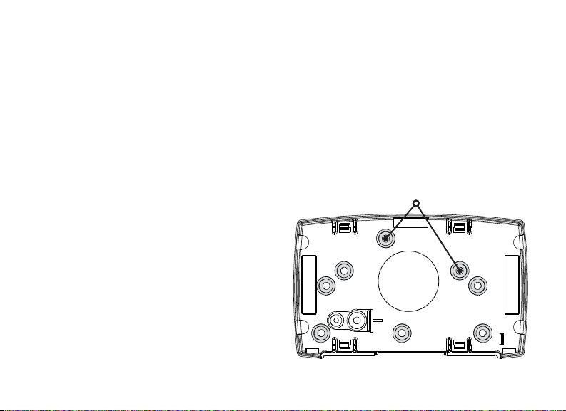
Refer to Figure 2 for mounting hole locations on the housing base.
1. Remove the PCB from the
plastic housing by loosening
the clips on one side and gently
lifting it out of the housing base.
2. Insert the included screws in the
desired mounting hole locations
and tighten them to secure the
housing to the surface.
3. Reinstall the PCB in the housing
base.
Figure 2: Mounting Hole Locations
4 734 Installation and Programming Guide | Digital Monitoring Products, Inc.
Mounting Holes
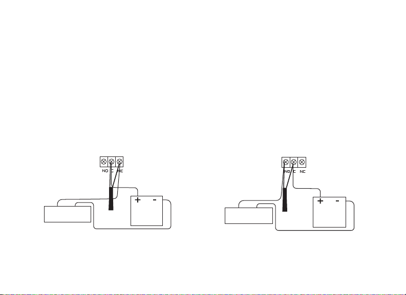
Wire the Access Control Lock
Normally Open
2
The 734 provides a Form C (SPDT) relay for controlling locks and other
electronically‑controlled barriers. The three relay terminals marked NO C NC allow
you to connect the device wiring to the relay for module control.
Use an additional power supply to power magnetic locks and door strikes. See
Figure 3 and Figure 4 for typical magnetic lock and door strike wiring.
The Form C relay draws up to 35mA of current and contacts are rated for 10Amps
(resistive) at 12/24VDC. When connecting multiple locks to the Form C relay, the
total current for all locks cannot exceed 10Amps. If the total current for all locks
exceeds 10Amps, problems may arise and an isolation relay may be needed. Refer
to “Isolation Relay (optional)” for more information.
Normally Closed
Power supply positive
Mag lock positive
to Terminal NC
–+
Magnetic Door
Lock
Model 333
Suppressor
Mag lock negative to
power supply negative
Figure 3: Typical Magnetic Lock Wiring
Digital Monitoring Products, Inc. | 734 Installation and Programming Guide 5
to Terminal C
12/24 VDC
Power Supply
Door strike positive
to Terminal NO
–+
DC Door Strike
Model 333
Suppressor
Door strike negative to
power supply negative
Figure 4: Typical Door Strike Wiring
Power supply positive
to Terminal C
12/24 VDC
Power Supply

KYPD IN / KYPD OUT Connections
• KYPD IN (Keypad In): Receives and transmits data to the panel Keypad bus/
AX‑Bus.
• KYPD OUT (Keypad Out): Receives and transmits data out to other keypad(s) or
module(s). Install a dual‑connector harness to allow connection to other devices
up to the maximum number of devices supported.
When the 734 is powered from 24VDC, do not connect devices to KYPD OUT header.
Status LEDs
The 734 board contains three status LEDs.
• The Red LED turns on for the same duration as the door strike relay.
• The Yellow LED turns on for one second to indicate receipt of a valid input
determined by card format programming.
• The Green LED indicates data sent to the panel.
6 734 Installation and Programming Guide | Digital Monitoring Products, Inc.
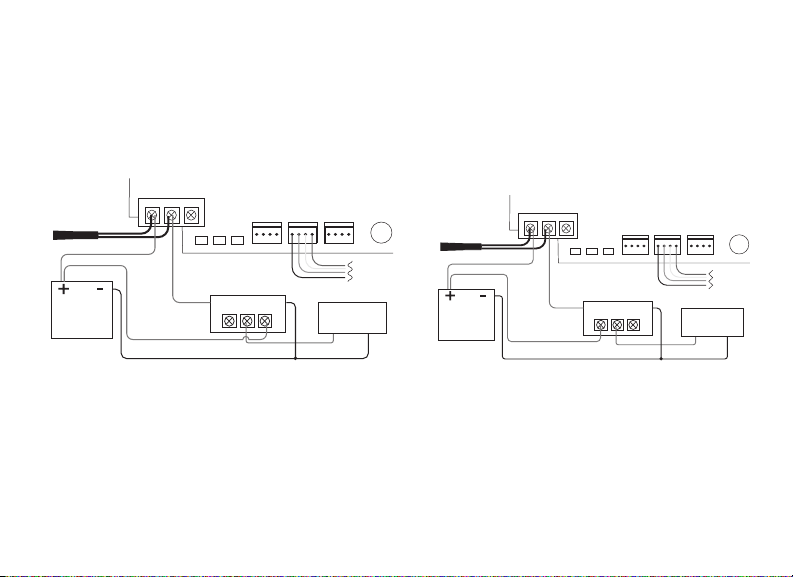
Isolation Relay (optional)
3
The Form C relay can control a device that draws less than 10Amps of current. If a
device draws more than 10Amps of current, or the sum of all devices controlled by
the Form C relay exceeds 10Amps, an isolation relay must be used. Refer to Figure 5
and Figure 6 for isolation relay wiring.
734
Series
DATA
PROG
XMT LED
Isolation Relay
NO C NC
–+
Module
RED
KYPD IN
RED
KYPD OUT
Magnetic Lock
Mag Lock
+
–
RED
To Panel
Keypad
Bus
–+
734
Series
RED
YEL GRN
WIEGAND
RELAY
READ LED
ON
Magnetic Lock
DATA
XMT LED
Isolation Relay
NO C NC
PROG
Module
PIEZO
RED
RED
KYPD OUT
Magnetic Lock
DC Door Strike
+
–
To Panel
Keypad
Bus
–+
+
RED
KYPD IN
–+
PIEZO
+
Model 333
Suppressor
–
Normally Open
12/24VDC
Power
Supply
NO C NC
+
+
–
+
Common
Normally Open
Figure 6: Door Strike with an Isolation
Relay
Model 333
Suppressor
12/24VDC
Power
Supply
Normally Open
NO C NC
+
Normally Closed
+
–
+
Common
RED
YEL GRN
WIEGAND
RELAY
READ LED
ON
Magnetic Lock
Figure 5: Magnetic Lock with an Isolation
Relay
Digital Monitoring Products, Inc. | 734 Installation and Programming Guide 7
–
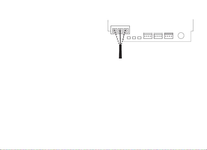
Install the 333 Suppressor
4
Use the included 333 suppressor with
the 734 to suppress any surges caused
by energizing a magnetic lock or door
strike.
Install the 333 across the module’s C
(common) and NO (normally open) or
NC (normally closed) terminals.
Model 333
Suppressor
NO CNC
RED
RELAY
ON
YEL GRN
WIEGAND
READ LED
734
Series
Module
PIEZO
–
RED
KYPD OUT
+
RED
DATA
PROG
XMT LED
KYPD IN
RED
If the device being controlled by the
relay is connected to the NO and C
terminals, install the suppressor on the
Figure 7: 333 Suppressor
Installation on the 734
NO and C terminals.
Conversely, if the device is connected to
the NC and C terminals, install the 333
Suppressor on NC and C terminals.
The suppressor wire is non‑polarized.
Install the suppressor as shown in
Figure 7.
8 734 Installation and Programming Guide | Digital Monitoring Products, Inc.

Wire the Zone Terminals
5
Terminals 8 through 12 connect grounded zones1 through 3. These zones have a
grounded side and cannot be used for fire‑initiating devices. Zones 2 and 3 can
also be used for access control with zone2 providing a bypass feature and zone3
providing request to exit functionality.
Terminals 13 and 14 connect to zone4. Zone 4 provides a non‑powered Class B
ungrounded zone suitable for connection to fire devices such as heat detectors or
pull stations.
Note: You must provide a mechanical means of resetting four‑wire smoke
detectors or other latching devices on zone4. The panel does not drop power
to the Keypad Bus or AX‑Bus when a Sensor Reset is performed.
Use the supplied 311 1k Ohm End‑of‑Line (EOL) resistors on each zone. Refer to the
panel programming guide for programming instructions. See Table 1 and Figure 8 for
more information on wiring the zone terminals.
Digital Monitoring Products, Inc. | 734 Installation and Programming Guide 9
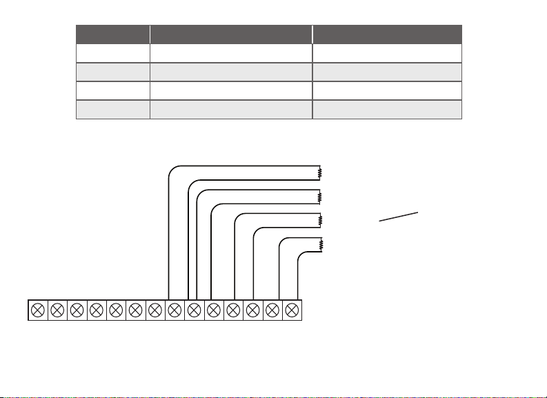
Zone # Recommended Device Residential Fire Device?
1 Any burglary device No
2 Door contact No
3 REX (PIR or Button) No
4 Any Device Yes
Table 1: 734 Zone Uses
Zone 1
Zone 2
Zone 3
Zone 4
10
8
2
1
4 5 6 7
3
LC ASRED WHTGRN BLK Z1 Z2 Z3 Z4+ Z4–RA GND GND
9
11 12 13 14
1k Ω EOL
1k Ω EOL
1k Ω EOL
1k Ω EOL
Zone 3 can also
be wired normally
closed with an
in‑line 1k Ohm
resistor
Figure 8: Zone Terminal Wiring
10 734 Installation and Programming Guide | Digital Monitoring Products, Inc.

6a
Digital Monitoring Products, Inc. | 734 Installation and Programming Guide 11
Connect a Wiegand Card Reader
The 734 provides direct 12/24VDC output to the reader on the Red terminal
connection. Figure 9 shows a reader with wire colors RED, WHT, GRN, and BLK
connecting to Terminals 1, 2, 3, and 4.
The green wire carries Data Zero (D0), and the white wire carries Data One (D1).
The red wire connects 12/24VDC and the black wire is ground.
The wire colors may be dierent depending on the reader being installed. Refer
to the literature provided with the reader for wire coding, wire distance, cable
type (such as shielded), and other specifications.
Wiegand Status Indicator Outputs
Terminals 5, 6, and 7 provide connections for Remote LED Control, Remote
Annunciation, and Armed Status indicators.
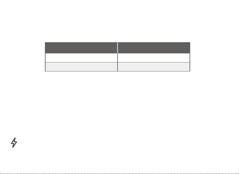
LC (Remote LED Control)
Remote LED Control provides an unsupervised switched ground for a visual indicator
that turns on when the relay activates. Connect the wire from the LC Terminal to an
LED. The LED turns on for the duration the door strike relay is on. HID readers optionally
provide a connection for LED reader control.
LC Wire Color LED Color
Orange Green
Brown Red
RA (Remote Annunciation)
Remote Annunciation provides an unsupervised switched ground for a remote
annunciator that turns on when the Zone 2Bypass timer expires. Connect the wire from
the RA Terminal to a remote annunciator. The remote annunciator silences when the RA
restores. The remote annunciator (RA) switched ground operates even if the speaker is
programmed not to operate.
AS (Armed Status)
Armed Status provides an unsupervised switched ground for a visual or audible armed
status indicator that turns on when the burglary areas are armed, such as SYSTEM ON or
ALL SYSTEM ON. Connect a wire from the AS Terminal to an armed status indicator.
Caution: Status indicator outputs support a maximum of 100mA per terminal.
Exceeding the maximum rating on LC, RA, or AS terminals can damage equipment.
12 734 Installation and Programming Guide | Digital Monitoring Products, Inc.
 Loading...