


How to install and operate the DLS Reference series car audio amplifiers
RA20 & RA40.
Welcome!
This owners manual is written in easy english and uses a lot of drawings to simply the installation and use of the above amplifiers.
Your DLS amplifiers must be installed correctly in order to work well. This manual will show you how to install the amplifier like a pro. Please read the entire manual before beginning the installation.
Install the amplifier yourself if you feel confident with our instructions and if you have the proper tools. However if you feel unsure, turn over the installation job to someone better suited to it.
Warranty Service
This amplifier is covered by warranty, depending on the conditions in the country where it is sold. If the amplifier is returned for service, please include the original dated receipt with the product.
Technical Assistance
For technical assistance ask the shop where the product was sold or the distributor in your very country.
You can always phone the DLS Helpdesk in Sweden + 46 31 84 00 60 or send an e-mail to info@dls.se.
Information can also be found on our WEB-site www.dls.se
Contents |
|
Features…………………………….. |
2 |
Installation…………………….……. |
2 |
Tools and materials needed………. |
3 |
Amplifier installation kit………….... |
3 |
Routing Wires…………………….... |
3 |
Wiring: |
|
Power and Outputs……………..…. |
4 |
Input and controls………………..... |
5 |
Input wiring..................................... |
5 |
Input level control.......................... |
6 |
Grand Bass..................………….... |
6 |
Phase control................................. |
6 |
Crossovers..................................... |
6 |
RA20 speaker wiring: |
|
Front speakers…...……………….... |
7 |
Subwoofer…………………………... |
7 |
RA40 speaker wiring: |
|
Four speakers…………………….... |
8 |
Two speakers + bridged subwoofer. |
8 |
Two speakers in bridge mode......... |
9 |
Testing……………………………….. |
9 |
Troubleshooting……………………... |
9 |
Professional tips…………………….. |
10 |
Specifications………………………... |
11 |
RA20
RA40
|
|
RA20 & RA40 |
|
|
|
All models include |
|
|
RCA inputs |
RA20 |
|
2 x 130 Watt RMS / 2 x 220 Watt max in 2 ohm |
||
High Level input |
1 x 440 Watt RMS bridged |
|
Continuos variable low pass and/or high- |
|
|
pass crossovers |
RA40 |
|
Grand bass feature 0 - +18 dB |
4 x 75 Watt RMS / 4 x 110 Watt max in 2 ohm |
|
Phase shift continously variabel 0-180 degr. |
2 x 220 Watt RMS bridged |
|
Remote turn on / off |
|
|
Automatic remote turn on/ off on high level |
All above RMS power ratings at 13,8 Volt DC. |
|
input without connecting any remote wire |
|
|
Electronic protection circuitry against |
|
|
short-circuit, DC offset and thermal overload. |
|
|
Bridgeable design to direct full power to |
|
|
one or two speakers. |
|
|
|
|
|
Installation
Before you begin installation |
Disconnect Battery |
Before you begin you need to read the manual, to have some tools, cables and other material available. There is one such list of material on the following page.
Amplifier location
Important
Allow air circulation around the amplifier.
The DLS Reference series of amplifiers have a compact design that allows great flexibility in mounting. You can mount it under a seat or in the trunk.
When you select a location, do remember that the amplifier generates a lot of heat.
Choose a location where air can circulate freely around the amplifier. Do not cover the amplifier with carpets or hide behind trim panels.
Do not mount the amplifier in an inverted or upside down position.
Check all locations and placements carefully before making any cuts, drilling any holes or making any connections.
This is the best way to mount the amplifier to get the best cooling.
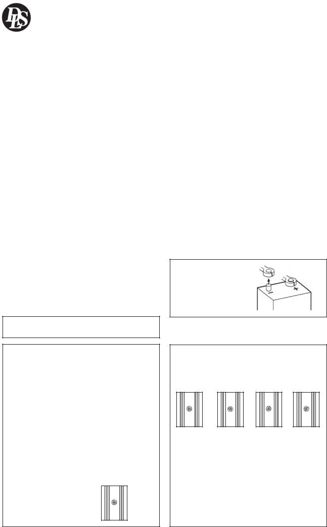
Before starting the installation, always disconnect the negative terminal of the battery.
DLS logo on amplifier cooling flange
The DLS logo on top of the amplifier is attached with two hex. screws. The logo can be removed and twisted 90 or 180 degrees, and then screwed back in wanted position. The logo can be mounted in four different ways to match your installation.
2

RA20 & RA40
Tools and material needed |
Routing wires |
Tools:
Flat and Phillips screwdrivers Wire cutter
Wire stripper
Electric drill with drills Crimping tool
Digital multimeter or test lamp
Wire brush, scraper or a piece of an abrasive sheet to remove
paint for a good ground connection
Grease to protect the ground connection from oxidation
Material:
Speaker wire: minimum
12 AWG = 4 mm2 for subwoofers
13 – 16 AWG = 1,5-2,5 mm2 for other speakers
Sheet metal screws for mounting the amplifier to the amplifier board and the amplifier board to the car + some extra for fuse holder, amplifier ground etc. Electrical insulation tape
½ inch thick plywood or particle board for the amplifier to be mounted upon.
Amplifier installation kit:
If available,buy an amplifier installation kit. It contains normally all you need. This is what you have to buy if you buy the items separately
2025 feet = 6- 7.5 meter power cable, minimum AWG 5 = 16 mm2 or heavier
1 pc of fuseholder to install close to the car battery + fuse 50 Ampere.
20 feet of AWG 15 = 1,5 mm2 wire for remote turn on / off cable from radio.
RCA-cable for input from radio.
- 20 feet or 5 meter for trunk installations
-12 feet or 2 – 3 meter for under seat installations
Two ring crimp terminals –one
for connection to the battery plus and one for the amplifier ground connection.
Four to eight splicers to connect speaker cables to high level input cable, if high level input is used.
Wire ties
Insulating grommet or insulating tube
Stereo head unit
Professional Tip:
If amplifier installation kits are available with different size of power cable, chose the most heavy power cable to improve sound quality and to allow more amplifiers to be installed now or later.
Use minimum AWG 5 = 16 mm2 cable, but if possible buy AWG 4 = PL 21 mm2 cable for best performance.
The ground cable must have the same size.
3
RA20 & RA40
Wiring
Power and Outputs
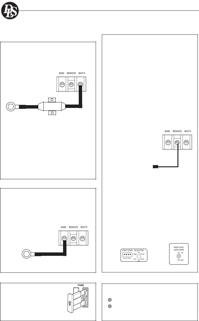
Power terminal ( +12V)
Connect the fuse holder as close to the vehicle battery + as possible, using AWG 5 = 16 mm2 or heavier cable. Use ring crimp terminal cable to connect to battery +. Apply silicon grease to the fuse to prevent corrosion.
Use a 50 Amp fuse.
|
DLS |
Connect with ring |
|
terminal to |
DLS FH1 |
battery + terminal |
fuse holder |
Connect the battery cable from the fuse holder to the +12 Volt terminal on the amplifier.
Be sure to use a rubber grommet or a plastic insulating tube where the cable passes the firewall or other places when it can easily be jammed.
Use ty-wraps to secure to existing cables in the engine compartment.
Ground Terminal ( GND )
Connect to a good chassis ground. The ground connection should be clean, unpainted metal to provide a good electrical connection. Use a wire brush, a scraper or a piece of an abrasive sheet to clean the metal. Use a lock washer or two to secure contact. Protect with silicon grease or by paint applied afterwards.
Remote terminal ( REM )
For RCA cable signal input:
Set the input selector switch to position ”Low level”. Connect the radio power antenna lead = remote turn on/off from the car stereo to the amplifier remote connection. This turns on the amplifier whenever the car stereo is turned on.
You can either use the built in remote cable in the RCA cable itself or use a separate cable as seen on page 4.
Sometimes a small disturbance may enter the amplifier coming from the remote voltage , through the built in remote wire and into the RCA cable. Thus we recommend to use a separate remote wire and run the RCA lead separate from remote wire, power cables and speaker cables.
Insert the cable directly into the amplifier terminal. If there is no remote voltage available from the stereo, you must connect to the ignition key through the radio or any accessories fuse.
Connect to head unit remote start terminal or power antenna lead
For High Level input:
Set the input selector switch to position ”High level”. We recommend you to connect the remote wire as described above. The amplifier will produce soft on / soft off operation this way. If you use a remote wire, set the switch ”High level auto start” to position OUT.
In the case that there is no remote voltage available from the car stereo, or you want to simplify the installation, the amplifier can be turned on/ turned off by the high level input voltage. This is done when the ”High level auto start” switch is set to IN
- position.
Connect with ring terminal to chassis ground
Fuses
Use only two 25 ampere ATC blade type fuses.
Power Light / Protect light
|
The power light (green ) comes on when |
Power |
the amplifier is turned on. |
(Green) |
|
|
The protect light ( red ) comes on |
|
when the amplifier shuts down from |
Protect |
overheating, or a short circuit ( spea- |
(Red) |
ker failure) |
|
4
 Loading...