

Page 1

Page 2

DSL-2750B
User Manual
ii
Page 3

Federal Communication Commission Interference Statement
This equipment has been tested and found to comply with the limits for a Class B digital device, pursuant to Part 15 of the FCC Rules. These limits are designed to
provide reasonable protection against harmful interference in a residential installation. This equipment generates, uses and can radiate radio frequency energy and, if
not installed and used i n accorda nce with the instruct ions, may cause harm ful interfere nce to radio c ommunic ations. However , there is no guar antee that interfere nce wil l
not occur in a partic ular in st allat ion. If this equipment does c aus e har mfu l inte rferen ce to r adio or t e levis ion recept ion, w hich ca n b e deter mined by turning t he equ ipm ent
off and on, the user is encouraged to try to correct the interference by one of the following measures:
- Reorient or relocate the receiving antenna.
- Increase the separat io n between the equipment and receiver.
- Connect the equipment int o an out l et on a circuit different from that to which the receiver is connected.
- Consult the dealer or an experienced radio/TV technician for help.
This device complies with Part 15 of the FCC Rules. Operation is subject to the following two conditions: (1) This device may not cause harmful interference, and (2) this
device must accept any int er ference received, including interference that may cause undesired operation.
FCC Caution: Any changes or modifications not expressly approved by the part y responsible for compliance could void t he user 's authority to operate this equipment.
IMPORTANT NOTE:
FCC Radiation Exposure Statement:
This equipment complies with FCC radiation exposure limits set forth for an uncontrolled environment. This equipment should be installed and operated with minimum
distance 20cm between the radiator & your body.
This transmitter must not be co-located or operating in conjunction wit h any other antenna or transmitter.
Page 4

Table of Contents
1 Safety Precautions ............................................................................................ 1
2 Introduction ........................................................................................................ 1
2.1 LEDs and Interfaces ................................................................................ 2
2.2 System Requirements ............................................................................. 4
2.3 Features ................................................................................................... 4
2.4 Standards Compatibility and Com pl iance ............................................... 5
3 Hardware Installation......................................................................................... 5
3.1 Choosing the Best Locatio n for Wireless Operation ............................... 5
3.2 Connecting the Router............................................................................. 6
4 About the Web Con figur ation ............................................................................ 7
4.1 Preparation Before Login......................................................................... 7
4.2 Logging In to the Router .......................................................................... 8
4.2.1 First-Time Login .......................................................................... 8
4.3 Setup ....................................................................................................... 9
4.3.1 Wizard ......................................................................................... 9
4.3.2 Internet Setup ............................................................................ 18
4.3.3 Wireless Connection ................................................................. 24
4.3.4 Local Network ........................................................................... 29
4.3.5 Time and Date ........................................................................... 31
4.3.6 Print Server ............................................................................... 32
4.3.7 Logout ....................................................................................... 32
4.4 Advanced ............................................................................................... 33
4.4.1 Wireless Settings ...................................................................... 33
4.4.2 Port Forwarding ......................................................................... 42
4.4.3 Port Triggeri ng ........................................................................... 44
4.4.4 DMZ ........................................................................................... 46
4.4.5 Parental Control ........................................................................ 46
4.4.6 Filtering Options ........................................................................ 50
4
.4.7 DNS ........................................................................................... 54
4.4.8 Dynamic DNS ............................................................................ 55
4.4.9 Storag e Service ......................................................................... 56
4.4.10 Multicast .................................................................................... 58
4.4.11 Network T oo ls ............................................................................ 59
4.4.12 Routing ...................................................................................... 71
4.4.13 RIP ............................................................................................ 74
4.4.14 MultiNat ..................................................................................... 74
4.4.15 Schedules ................................................................................. 75
4.4.16 Logout ....................................................................................... 76
4.5 Maintenance .......................................................................................... 77
4.5.1 System ...................................................................................... 77
4.5.2 Firmware Update....................................................................... 78
4.5.3 Access Controls ........................................................................ 78
4.5.4 Diagnostics ................................................................................ 81
4.5.5 System Log ............................................................................... 82
4.5.6 Logout ....................................................................................... 82
4.6 Status ..................................................................................................... 83
4.6.1 Device Info ................................................................................ 83
4.6.2 Wireless Clients ........................................................................ 84
4.6.3 DHCP Clients ............................................................................ 84
4.6.4 Logs ........................................................................................... 85
4.6.5 Statistics .................................................................................... 86
4.6.6 Route info .................................................................................. 87
4.6.7 Logout ....................................................................................... 87
5 FAQs ................................................................................................................ 88
DSL-2750B User Manual i
Page 5

1 Safety Precautions
Follow the following instructions to prevent the device from risks and damage caused by fire or electric power:
Use volume labe ls t o mark the type of power .
Use the power ada pt er packed within the device pack age.
Pay attention to the power load o f the outlet or prolonged lines. An overburden power outlet or dam aged lines and plugs may cause electric shock or fire accident.
Check the power cords regul ar ly. If you find any damage, replace it at once.
Proper space left for heat dissipation is necessary to avoid damage caused by overheating to the device. The long and thin holes on the device are designed for
heat dissipation to ensure that the dev ice w orks normally. Do not cover these heat dissipation holes.
Do not put this dev ice close to a place where a heat source exists or high temperature occurs. Avoid the device from direct sunshine.
Do not put this device close to a place where it is over damp or watery . Do not spill any fluid on this device.
Do not conne ct t his dev ice to any PCs or electronic product s, u nless our c ust omer eng ineer or your broa dband pr ovi der i nstruct s y ou to d o t his, becaus e a ny wrong
connection may cause power or fire risk.
Do not place this d evice on an unstable surface or support.
2 Introduction
The DSL-2750B is a highly integrated ADSL2/2+ Integrated Access Device. It provides DSL uplink, Ethernet LAN and wireless LAN services. The wireless LAN is
complied with the IEEE802.11b/g /n standards and supports 2T2R. It is usually prefered to provide high access performance applications for the individual users, the
SOHO, the small enterprise and so on.
DSL-2750B User Manual 1
Page 6

2.1 LEDs and Interfaces
The LED indicators are as follows from left to right: Power, LAN1/2/3/4, WLAN,
LED
Color
Status
Description
Off
The power is off.
The power is on and the initialization is
normal.
On
The device is initiating.
Blinks
The firmware is upgrading.
Off
No LAN link.
Data is being transmitted through the LAN
interface.
On
The connection of LAN inter face is normal.
Data is transmitted through the WLAN
interface.
On
The connection of WLAN int er face is normal.
The connection of USB fla sh disk has
established.
Blinks
The device is detecting itself.
On
Initial self-test of the unit has passed.
The device is under the Bridge mode, DSL
connection is not present, or the power is off.
On
IP is connected and no traffic is detected.
The device is attempted to become IP
connected, but failed.
WPS (on
the side
panel)
WPS negotiation is enabled, waiting for the
clients.
Off
Device is ready for new WPS to setup.
Front Panel
USB, DSL, Internet. The WPS indicator is on the side panel.
The following table describes the LEDs of the device.
Green
Power
Red
LAN 1/2/3/4 Green
On
Blinks
Blinks
WLAN Green
Off The WLAN connection is not established.
On
USB Green
Blink Data is being trans mitted.
Off No signal is detected.
Off Initial self-test is failed.
DSL Green
Green
Off
Internet
Red On
Green
Blinks
DSL-2750B User Manual 2
Page 7

Rear Panel
Interface/Button
Description
RJ-11 interface that connect s to the t e lephon e set t hr ough
the telephone cable.
Ethernet RJ-45 interfaces that connect to the Ethernet
interfaces of computers or Et her net devices.
USB
USB host port, for connecting the USB storage devices.
WIRELESS
ON/OFF
Reset to the factory defaults. To restore factory defaults,
release.
ON/OFF
Power on or off.
Interface that connects to the power adapter. The power
adapter output is: 12 V DC, 1 A.
side panel)
DSL
LAN4/3/2/1
Button to enable or disable WLAN.
RESET
POWER
WPS (on the
keep the device powered on and push a paper clip into
the hole. Press down the but t on for one second, and then
WPS button to setup connect ion to client.
DSL-2750B User Manual 3
Page 8

2.2 System Requirements
Recommended system requirements are as follows:
An 10 baseT/100BaseT Ethernet card is inst al led on your PC
A hub or switch (attached to several PCs through one of Eth er net interfaces on the device)
Operating system: Windows 98SE, Windows 2000, Windows ME, Windows XP, Windows Vista or Windows 7
Internet Explorer V5.0 or higher, Netscape V4.0 or higher, or Firefox 1.5 or higher
2.3 Features
The device supports the following features:
User-friendly GUI for web configuration
Several pre-configured popular games. Just enable the game and the por t settings are automatically configured.
Compatible with al l standard Internet applications
Industry standard an d interoperable DSL interfac e
Simple web-based status page display s a snapshot of system configuration, and links to the configuration pages
Downloadable flash software updates
Support for up to 8 permanent virtual circuits (PVC)
Support for up to 8 PPPoE sess io ns
Support RIP v1 & RIP v2
WLAN with high-speed data transfer rates of up to 130 Mbps, compatible with IEEE 802.11b/g/n, 2.4GHz compliant equipment
Optimized Linux 2.6 Operating System
IP routing and bridging
Asynchronous transfer mode ( AT M ) and digital subscriber line (D SL) support
Point-to-point protocol (PPP)
Network/port address translati on ( N AT/PAT)
Quality of service (QoS)
Wireless LAN security: WPA, 802.1x, RADIUS client
Universal plug-and-play(UPnP)
File server for network attached storage (NA S) devices
Print server
Web filtering
Management and control
- Web-based management (WBM)
- Command line interface (CLI)
- TR-069 WAN management protocol
Remote update
USB mass-storage
System statistics and monitoring
DSL-2750B User Manual 4
Page 9

2.4 Standards Compatibi lity and Compliance
Support application level gateway (ALG)
ITU G.992.1 (G.dmt)
ITU G.992.2 (G.lite)
ITU G.994.1 (G.hs)
ITU G.992.3 (ADSL2)
ITU G.992.5 (ADSL2+)
ANSI T1.413 Issue 2
IEEE 802.3
IEEE 802.3u
IEEE 802.11b
IEEE 802.11g
IEEE 802.11n
3 Hardware Installation
3.1 Choosing the Best Location for Wir el ess Operation
Many environmental factors may affect the effective wireless function of the DSL Router. If this is the first time that you set up a wireless network device, read the
following information:
The access point can be placed on a shelf or desktop, ideally you should be able to see the LED indicators in the front, as you may need to view them for
troubleshooting.
Designed to go up to 100 meter s indoors and up to 300 meters outdo or s , wireless LAN lets you access your network from anywhere you want. Howev er, the numbers
of walls, ceilings, or other objects that the wireless signals must pass through limit signal range. Typical ranges vary depending on types of materials and background
RF noise in your home or busines s.
DSL-2750B User Manual 5
Page 10

3.2 Connecting the Router
Connect the DSL port of the router and the Modem port of the splitter
with a telephone cable; connect the phone to the phone port of the
(1)
splitter through a cable; and connect the incoming line to the Line port of
the splitter.
The spliiter has three ports:
LINE: Connect to a w al l phone jack (RJ-11 jack)
Modem: Connect to the Line interface of the router
PHONE: Connect to a telephone set
(2) Connect the LAN port of the router to the network interface card (NIC) of
the PC through an Ethernet cable (MDI/MDIX).
(3) Plug the power adapter to the wall outlet and then connect the other end
of it to the Power port of the router.
DSL-2750B User Manual 6
Page 11

Configure the IP address of the PC as 192.168.1.X (2~254), net mask as
.1 (for customized version,
configure them according to the actual version).
Enter arp -a in the DOS window to check whether the PC can read the MAC
Ping the MAINTENANCE IP address (192.168.1.1 by default) of the Router.
4 About the Web Configuration
The first time you setup the Router. It is recommended that you configure the WAN connection using a single computer, to ensure that both the computer and the
Router are not connected to the LAN. Once the WAN connection operates properly, you may continue to make changes to Router configuration, including IP settings
and DHCP setup. This chapter is concerned with using your computer to configure the WAN connection. The following chapter describes the various menus used to
configure and monitor the Router, including how to change IP settings and DHCP server setup.
4.1 Prep aration Before Login
Before accessing the Routerre the communication between PC and Router is normal. Check the commu nication as follows.
255.255.255.0, gateway address as 192.168.1
address of the Router.
If the PC can read the MAC address of the Router and can ping through the
MAINTENANCE IP address of the Router, that means the communication of
the PC and the Router is nor ma l.
Note:
DSL-2750B User Manual 7
When you manage the Router through Web, you mu st k eep t he Router
power on. Otherwise, the Router may be damaged.
Page 12

Step 1
Step 4 Click Login to log in.
4.2 Logging In to the Router
The following description i s a detail “How-To” user guide and is prepared for first time user s.
4.2.1 First-Time Login
When you log in to the DSL Router for t he f irst time, the login wizard appears.
Open a Web browser on your co mp ut er .
Step 2 Enter http://192.168.1.1 (DSL router default I P address) in the
address bar. The login page appears.
Step 3 Enter a user name an d t he password. The default usernam e and
password of the super user ar e admin and admin. The username
and password of the common user ar e user and user. You need not
enter the username and pass w or d again if you select the option
Remember my pass wor d. It is recommended to change these
default values after logging in to the DSL router for the first time.
DSL-2750B User Manual 8
Page 13
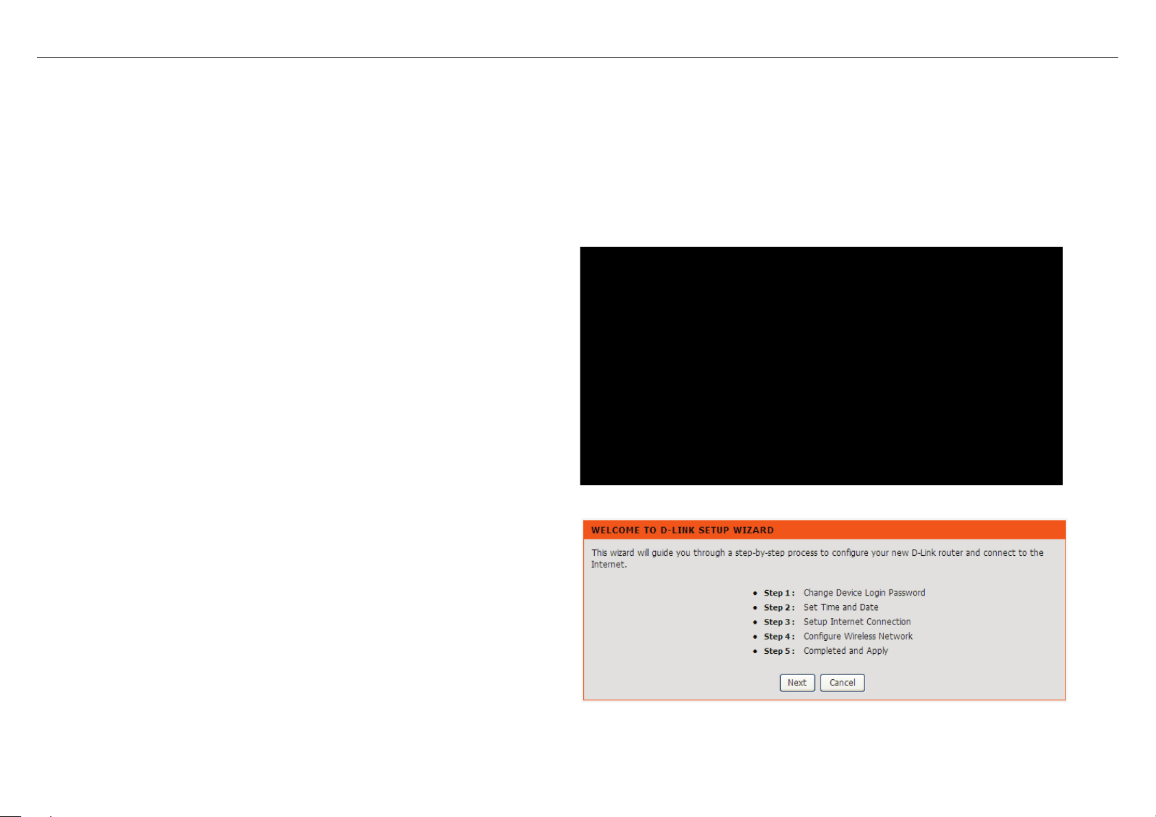
Choose Setup > Wizard. The page shown in the fig ur e appears.
Click Setup Wi zard. The page shown in the right figure appears.
4.3 Setup
4.3.1 Wizard
Wizard enables fast and accurate configuration of Internet connection and other important parameters. The following sections describe these various c onfigur ation
parameters.
When subscribing to a broadband service, you should be aware o f the method, by which you are connected t o the Internet . Your physical WAN dev ice can be Ethernet ,
DSL, or both. Technical information about the properties of your Internet connection is provided by your Internet service provider (ISP). For example, your ISP should
inform you whether you are connected to the Internet using a static or dynamic IP address, or the protocol, such as PPPoA or PPPoE, that you use to communicate
over the Internet.
DSL-2750B User Manual 9
Page 14
There are four steps to configure the device. Click Next to continue.
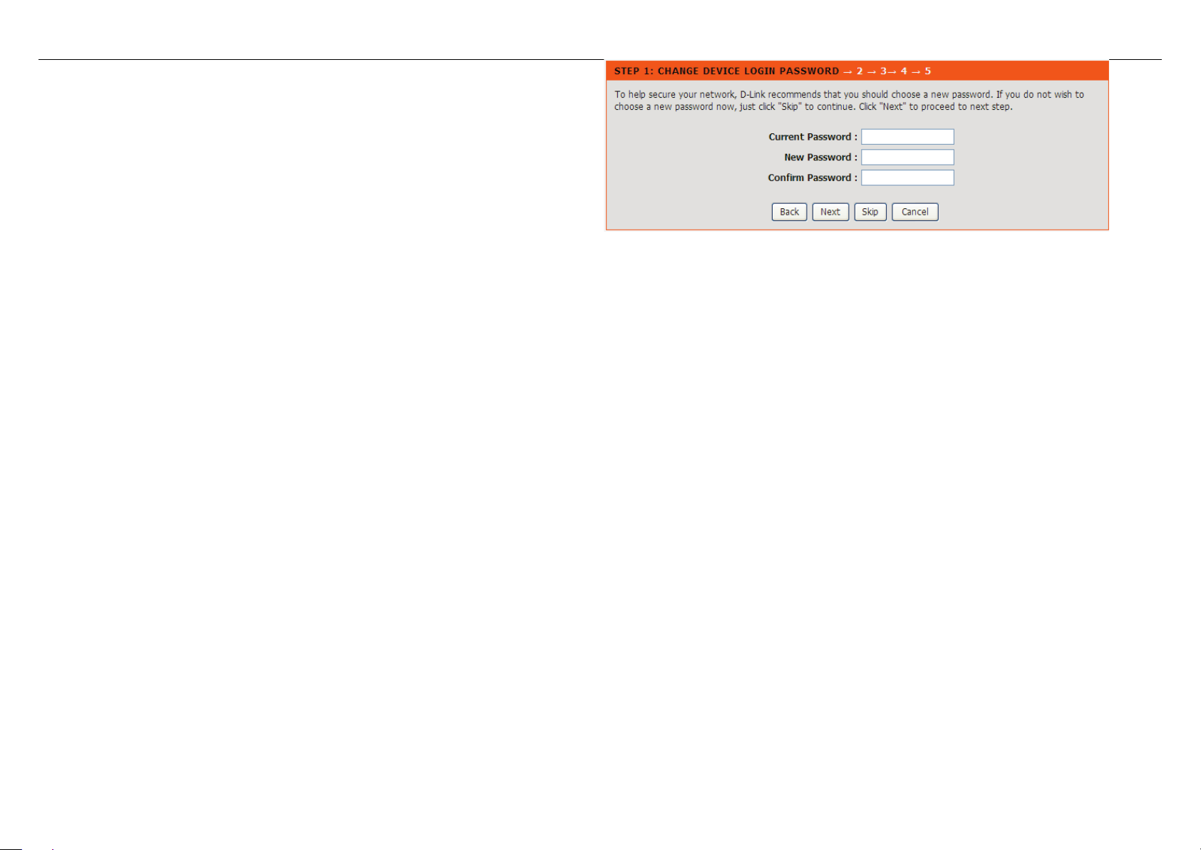
Change the password for logging in to the device.
The default password is admin. To secure your network, modify the password
timely.
Note:
Confirm password must be the same as the new password.
To ignore the step, click Skip.
DSL-2750B User Manual 10
Page 15
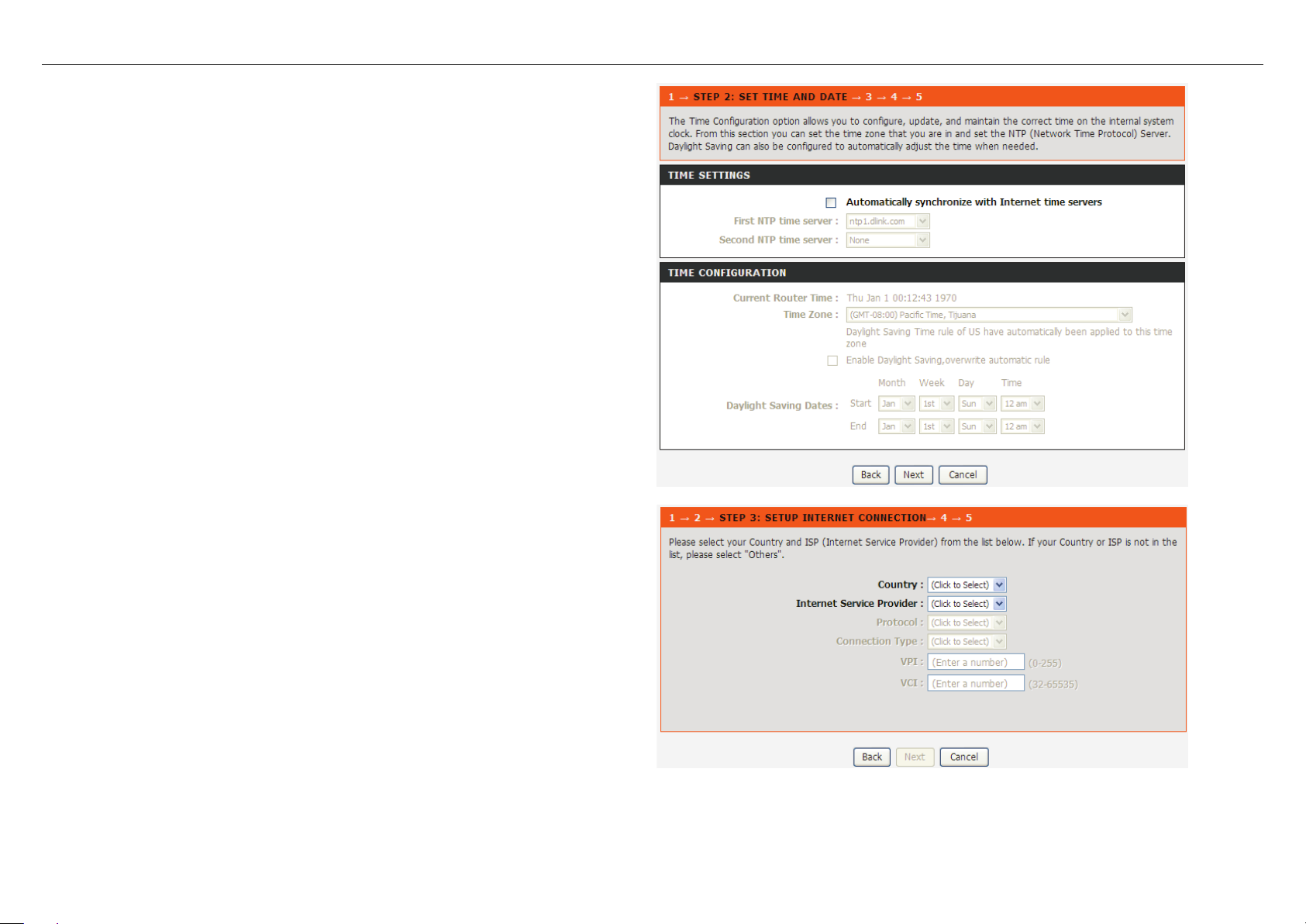
Set the time and date.
Configure the Internet connection.
You can select
First NTP time server: Select the domain of the time server to which system
time will be synchronized.
Select the country and ISP. Set the VPI and VCI. If you fail t o find the country
and ISP from the drop-down lists, select Others.
Protocol: The protocol connection type of the interface.
PPPoE, PPPo A, Dynamic IP, St a t ic IP, or Bridge.
Connection Type: You can select it from the drop-dow n list acc ordi ng to t he
uplink equipment. You can select LLC or VC-Mux.
VPI: The virtual path identifier of the WAN interface (provided by your ISP).
The range is 0 to 255.
VCI: The virtual channel identifier for the WAN interface. The range is 32 to
65535 (1 to 31 are reserved for know n pr otocols).
DSL-2750B User Manual 11
Page 16
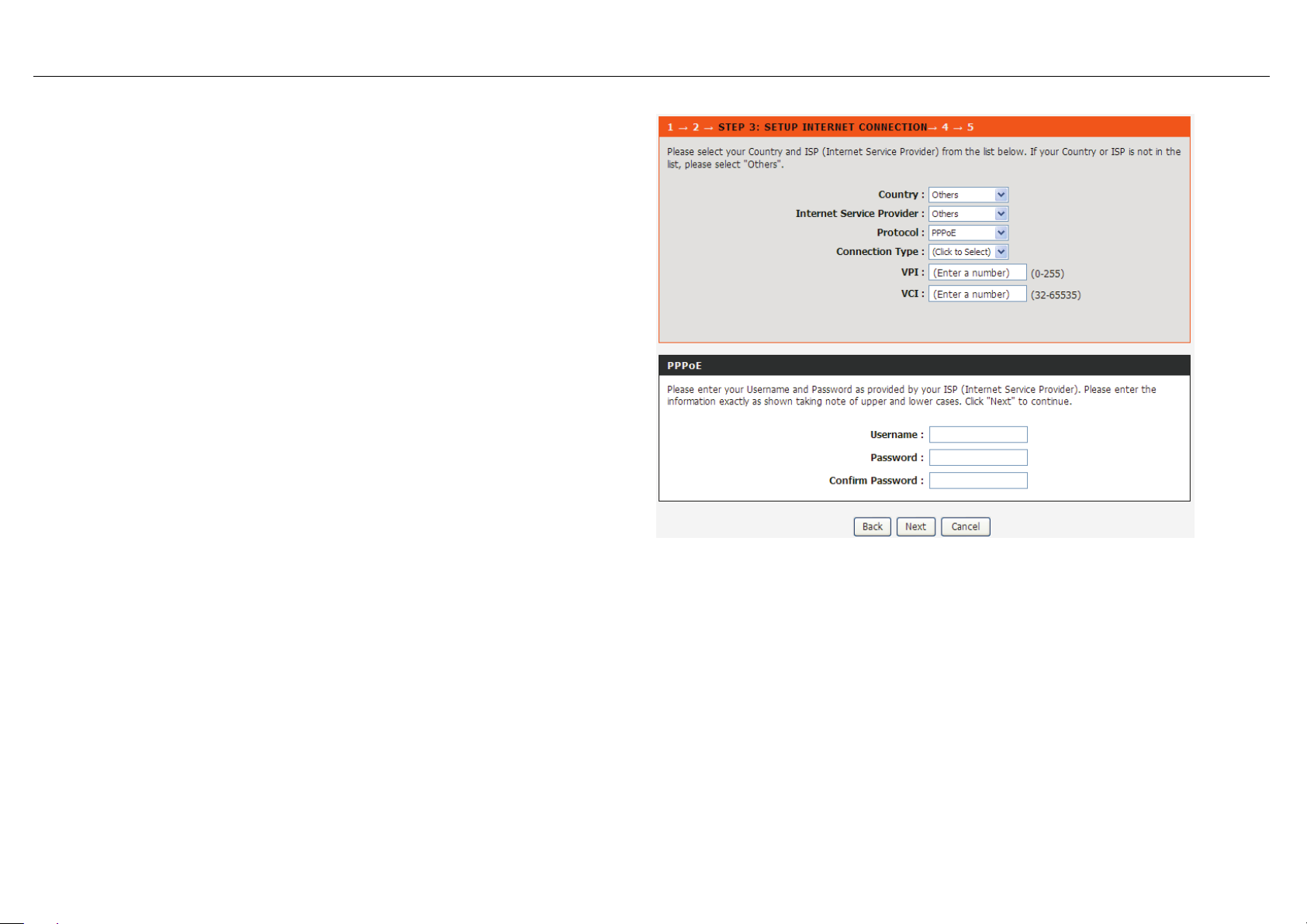
If the Protocol is PPPoE or PPPoA, the page s how n i n e i the r of the two figures
appears.
DSL-2750B User Manual 12
Page 17
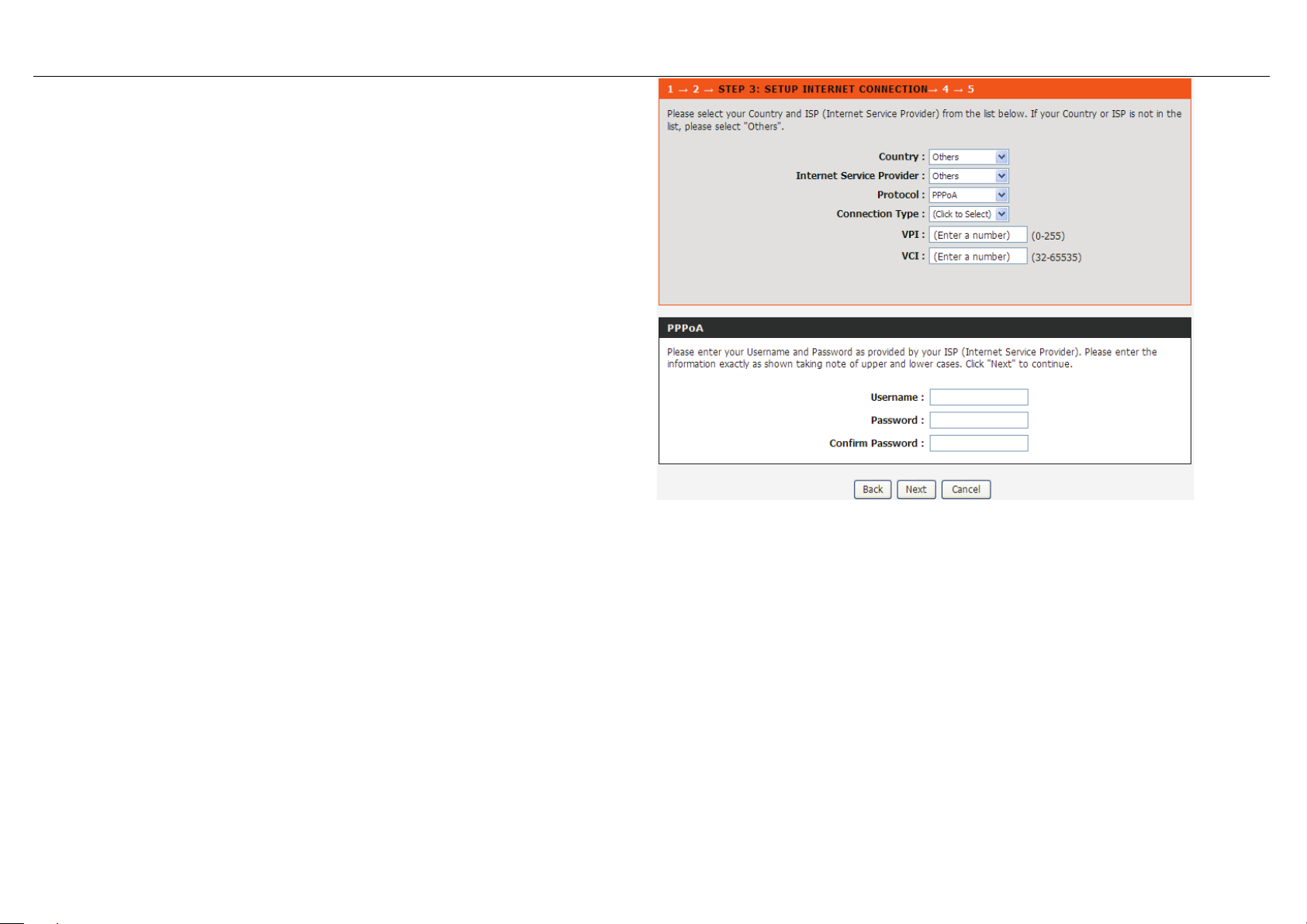
Set the user name and password as provided by your ISP.
DSL-2750B User Manual 13
Page 18
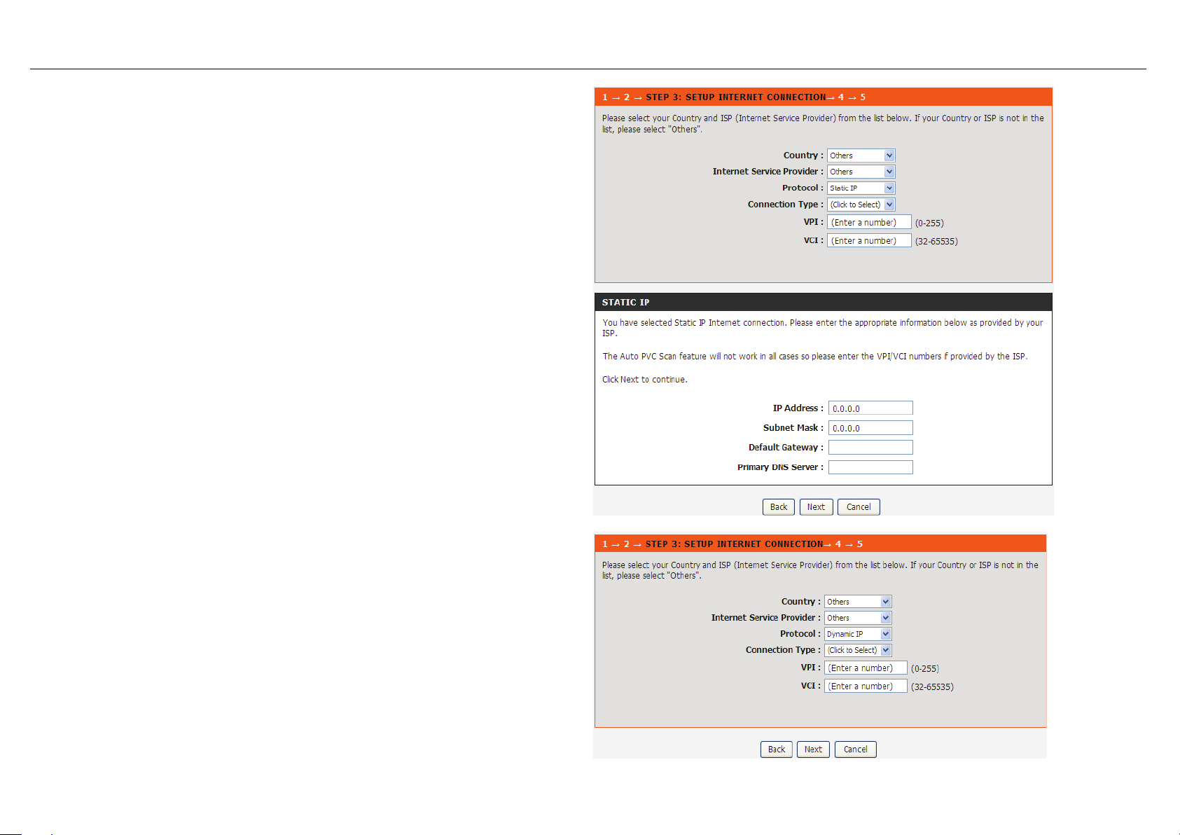
If the Protocol is Static IP, the page shown in the figure appears.
Enter the IP Address, Subnet Mask, Default Gateway, and Primary DNS Server.
If the Protocol is Dynamic IP or Bridge, the page shown in the figure appears.
DSL-2750B User Manual 14
Page 19
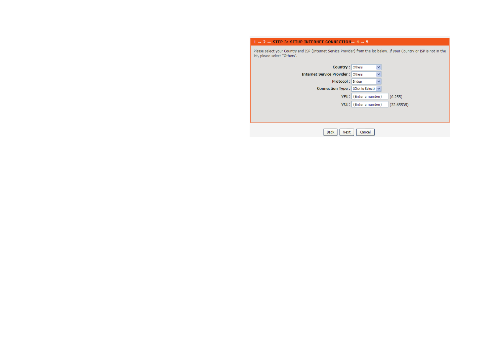
After proper configur at ion, click Next.
DSL-2750B User Manual 15
Page 20
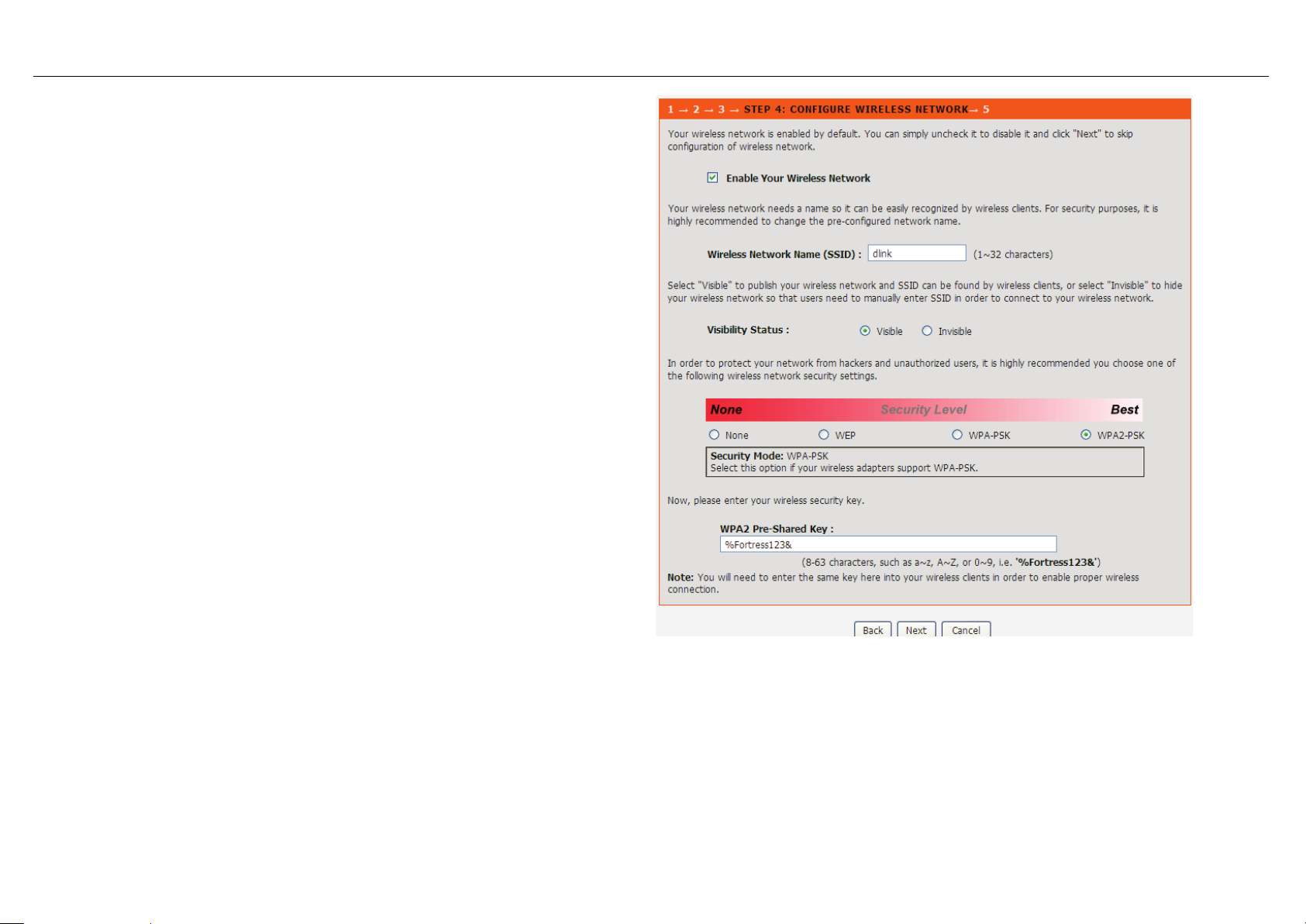
Configure the wireless network, or keep the default settings. Enter the
: SSID is the name of your wireless
equipped devices share the same SSID to
communicate with each other. It must be unique to identify separated
uld change the default SSID to a
In order to protect your network from hackers and
unauthorized users, it is highly recommended you choose one of the
key here into your wireless clients in order to enable proper wireless
information and click Next.
Enable Yo ur Wirel ess Net work: Enable wire less settings on LA N interface.
Wireless Network Name (SSID)
network. All wirelesswireless network. For security, you sho
special ID.
Visibility Status: You can select visible or invisible.
Security Level:
following wireless network security settings.
W PA Pre-Shared Key: Please set it. Then you will need to enter the same
connection.
DSL-2750B User Manual 16
Page 21
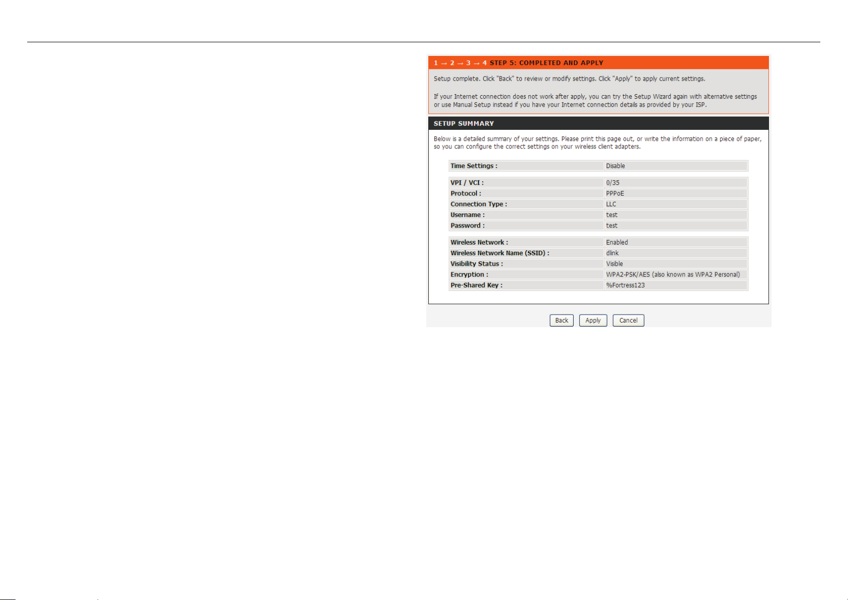
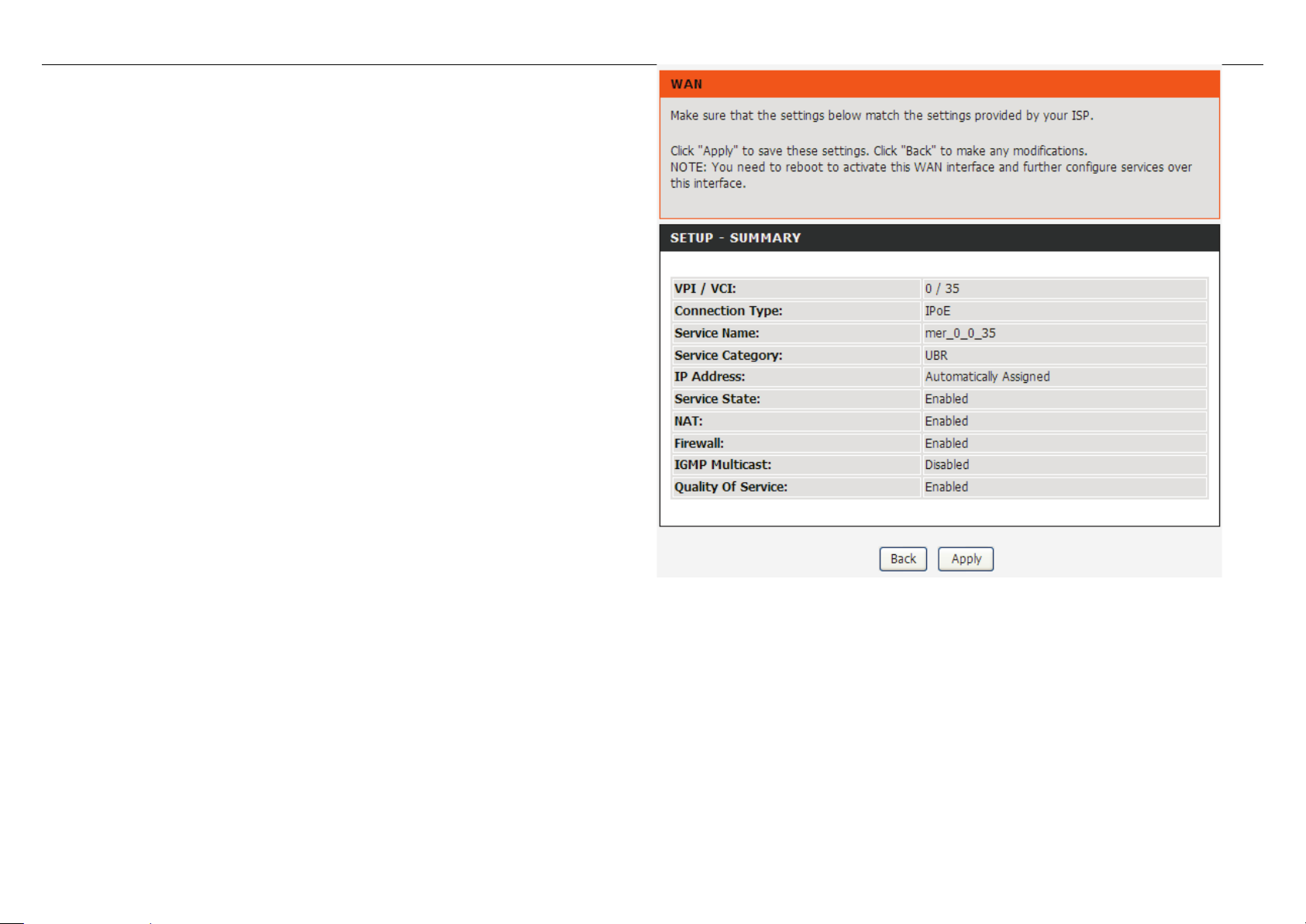
The page shown in the right figure appears. In this page, you can view the
configuration information. You can check weather the configurations match the
information provided by your I SP.
DSL-2750B User Manual 17
Page 22
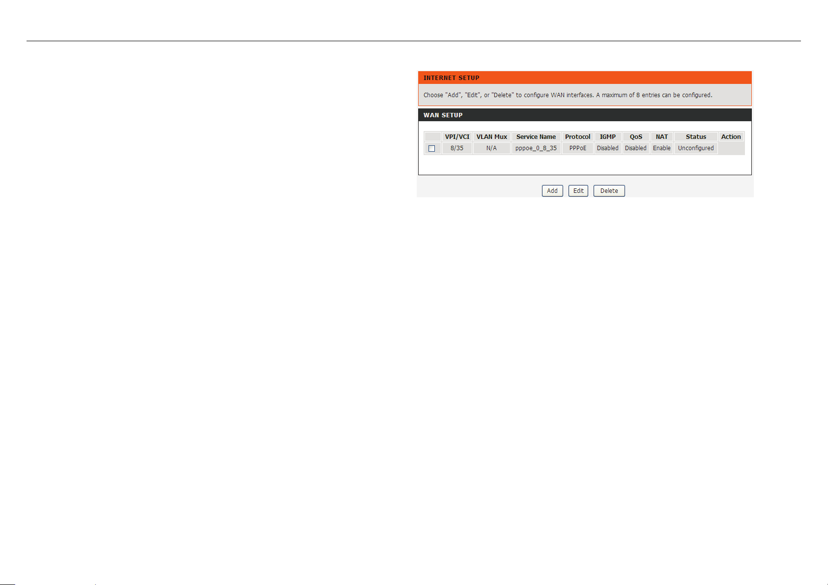
4.3.2 Internet Setup
Choose Setup > Internet Setup. The page as shown in the right figure
appears. In this page, you can configure the WAN in terface of the device.
DSL-2750B User Manual 18
Page 23
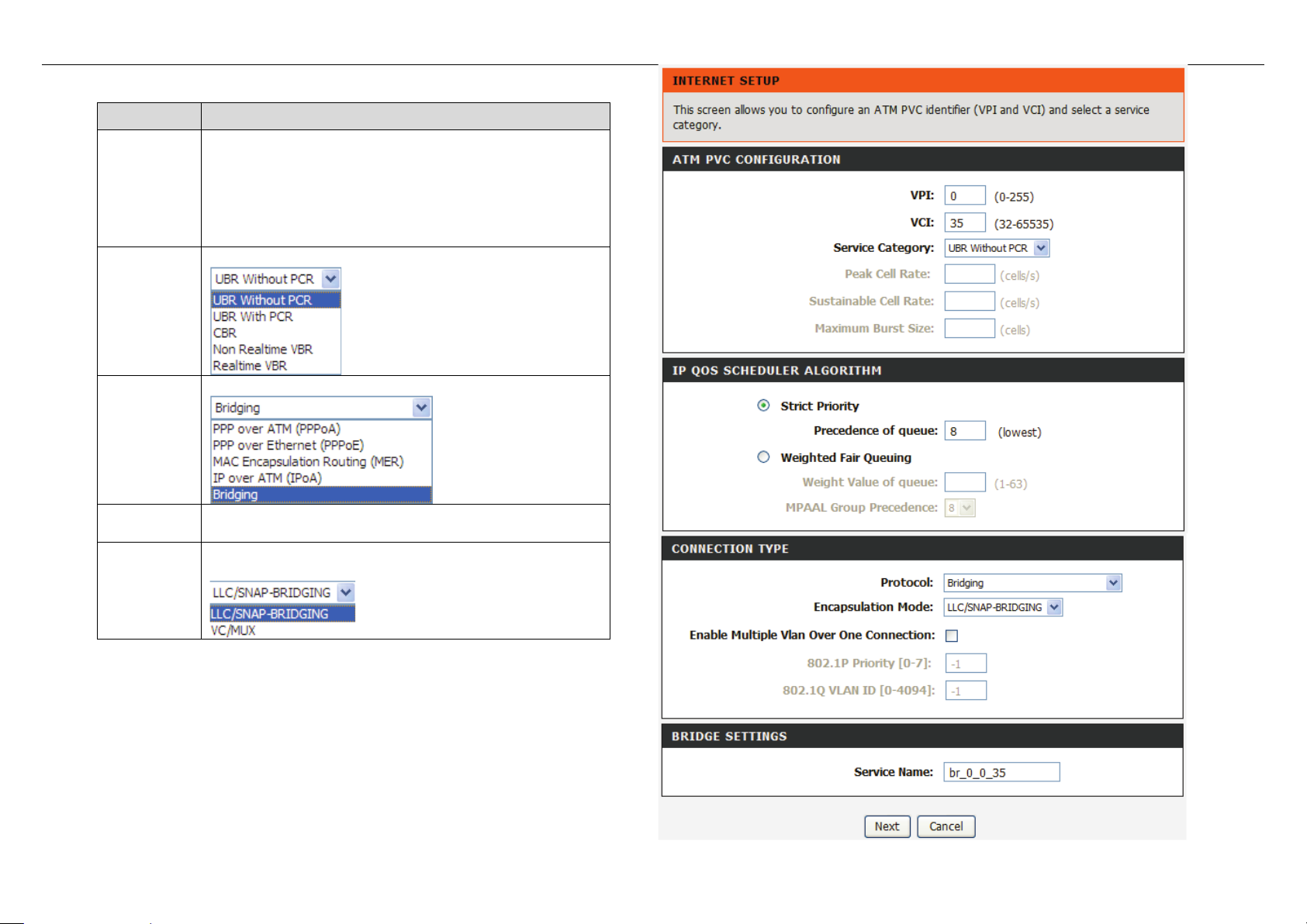
Click Add in “INTERNET SETUP”. The page shown in the following figure
appears.
Field
Description
reserved for local manage me nt of ATM traf f ic) .
You can select from the drop-down list.
You can select from the drop-down list.
QoS
scheduler
You can select one of the item between Strict Priority
and Weighted Fair Queuing.
Select the method of encapsulation provided by your
PVC
Settings
The virtual path between tw o points in an ATM
network and its valid value is from 0 to 255.
The virtual channel between tw o points in an A TM
network, ranging from 32 t o 65535 (0 to 31 is
Service
Category
Protocol
Encapsulati
ISP. You can select from the drop-down list.
on Mode
DSL-2750B User Manual 19
Page 24
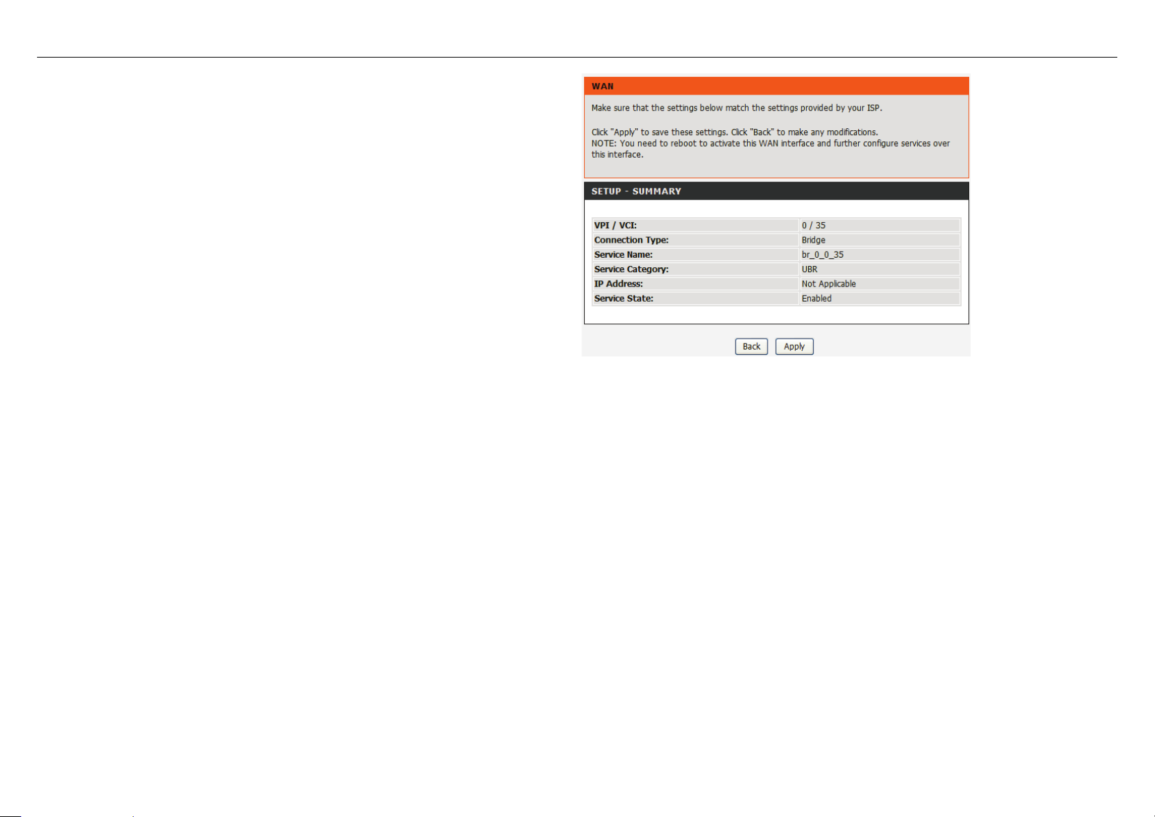
Click Next, the page shown in the f ol low i ng figure appears.
DSL-2750B User Manual 20
Page 25
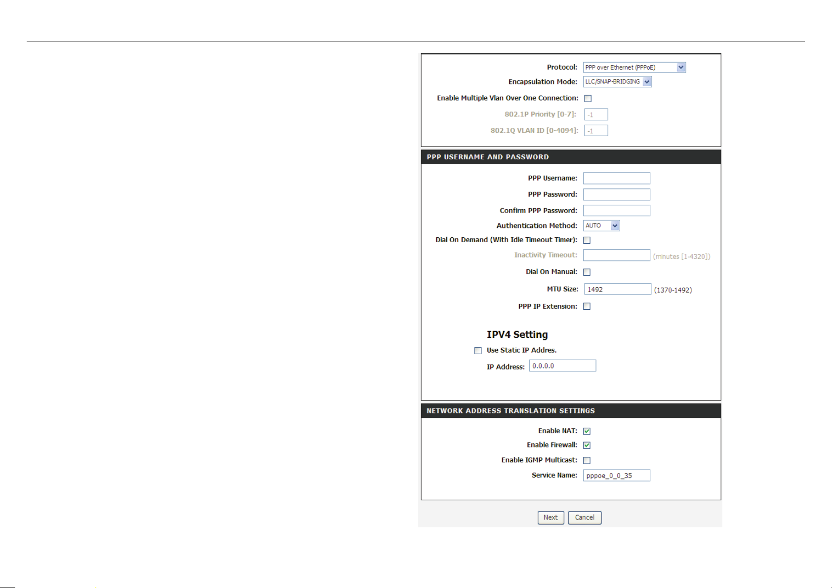
If you select the PPP over Ethernet (PPPoE) or PPP over ATM (PPPoA) as
The value can be AUTO, PAP, CHAP, or
IP address
the connection protocol, t he fo ll ow ing page appears.
PPP Username: The correct user name that y our ISP provides to you.
PPP Pas s wor d : The corr ect password that your ISP provides to you.
Authentication Method:
MSCHAP. Usually, you can select AUTO.
Dial on demand (with idle timeout timer): If thi s function is enabled,
you need to enter the idle timeout time. Within the preset minutes, if the
router does not detect the flow of the user continuously, the router
automatically stops the PPPoE connection. Once it detects the flow (like
access to a webpage), the router restarts the PPPoE dialup.
If this function is disabled, the router performs PPPoE dial-up all the
time. The PPPoE connnection does not stop, unless the router is
powered off and DSL AM or uplink equipment is abnormal.
MTU Size: Maximum Transmission Unit. Sometimes, you must modify
this function to access network successfully.
PPP IP extension: If this function is enabled, the WAN
obtained by the router through built-in dial-up can be directly assigned to
the PC being attached to the router ( at this time, the router connects to
only one PC). From the aspect of the PC user, the PC dials up to obtain
an IP addres. But actually, the dial-up is done by the router. If this
function is disabled, the router itself obtains the WAN IP address.
Use Static IP Address: If this function is disabled, the router obtains an
IP address assigned by an uplink equipment such as BAS, through
PPPoE dial-up.
If this function is enabled, the router uses this IP address as the WAN IP
address.
Enable NAT : Select it t o enable the NAT functions of the router. If you do
not want to enable NAT and wish the router user to access the Internet
normally, you must add a route on the uplink equipment. Otherwise, the
access to the Internet fails. Normally, NAT should be enabled.
Enable Firewall: Enable or disable IP filtering.
Enable IGMP Multicast: IGMP proxy. For example, if you w ish that the
PPPoE mode support s I PTV, enable this function.
DSL-2750B User Manual 21
Page 26
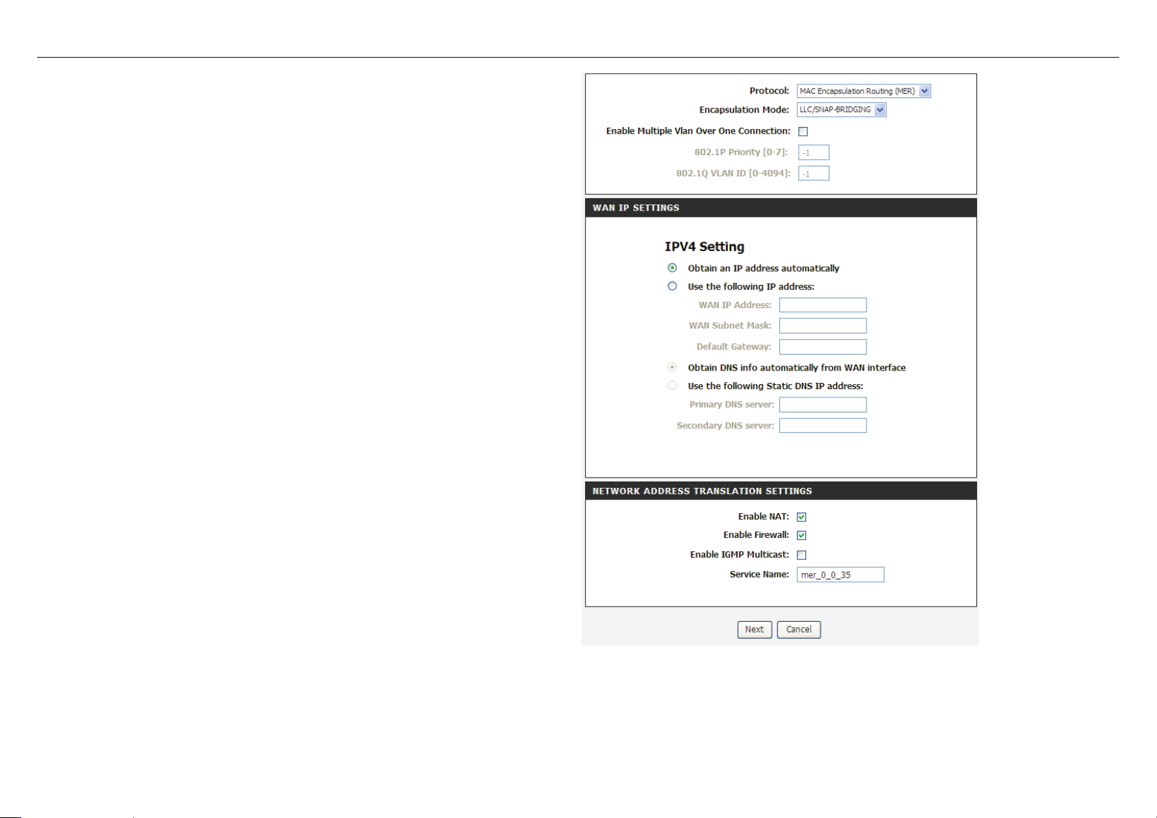
If you select the MAC Encapsulation Routing(MER) as the connection
protocol, the following p age appears.
Obtain an IP address automatically: The modem obtains a W AN IP
address automatically and at this time it enables DHCP client functions.
The WAN IP addre ss is obtained from the uplink equipment like BAS and
the uplink equipment is re quired to enable the DHCP server functions.
Use the followi ng IP addr ess: If you want to manually enter t he WAN IP
address, select this check box and enter the information in the field.
W A N IP A ddress: Enter the IP ad dress of th e WAN interfac e prov ided by
your ISP.
WAN Subnet Mask: Enter the subnet mask concerned to the IP address
of the WAN interface provided by your ISP.
Default Gateway: Enter the de fau lt gat ew ay.
Obtain DNS info automatically from WAN interface: You can get DNS
server information fro m the selected WAN interface
Use the following S t atic D NS IP addre ss: If you want to manually enter
the IP address of the DNS server, select this check box and enter the
information in the fields.
Primary DNS server: Enter the IP address of the primary DNS server.
Secondary DNS server: Enter the IP address of the secondary DNS
server provided by your ISP.
DSL-2750B User Manual 22
Page 27
After proper settings, click Next.
DSL-2750B User Manual 23
Page 28
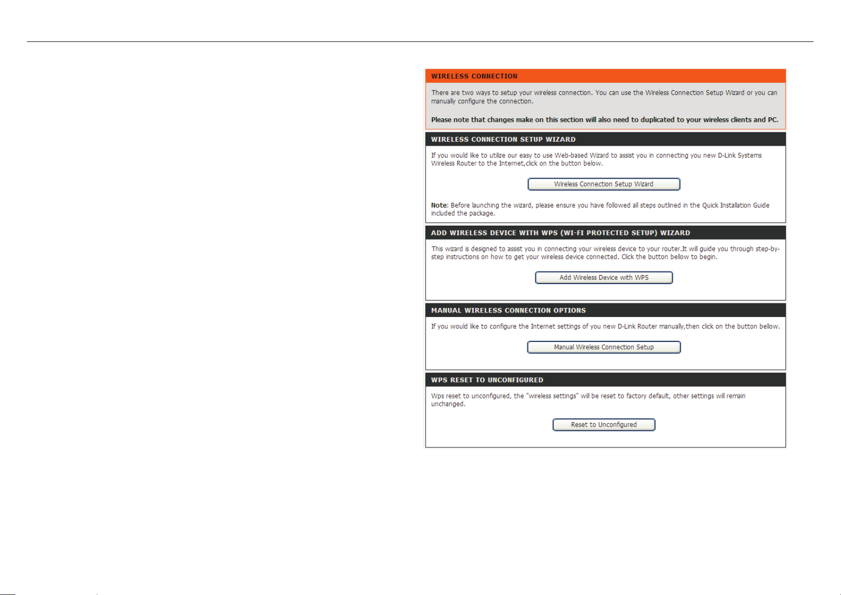
4.3.3 Wireless Connection
This section includes the wireless connection setup wizard and WPS setup
or you can manually configure the
wizard. There are two ways to setup your wireless connection. You can use the
Wireless Connection Setup Wizard
connection.
Choose Setup > Wireless Connection. The Wireless Connection page
shown in the following figure appears.
DSL-2750B User Manual 24
Page 29

4.3.3.1 Wireless Wizard
In Wireless Connection page, Click “Wireless Connection Setup Wizard”,
If you select “Use WPA encryption instead of WEP” and “Manually assign a
the page shown in the follow ing figure appe ars.
network key”, click “Next”, the page shown in the following figure appears.
DSL-2750B User Manual 25
Page 30

If you only select “Manually assign a network key”, click “Next”, the page
shown in the following figure appears.
After you enter the network key , the page shown in the follow ing figur e appear s ,
you can confirm the wireless settings in this page.
Click Save to save the settings.
DSL-2750B User Manual 26
Page 31

4.3.3.2 Wireless Device Add
In Wireless Connection page, Click Add Wireless Device with WPS, the
Select Auto, click Next, the page shown in the follo wing figure appears.
Select Manual, click Next, the page shown in the fo llowing figure appears.
page shown in the following figure appears.
When PIN is used, users are only allowed to enter no more than eight digits in
the field.
It displays the current wireless setti ngs and you can manually enter the settings
in the wireless device that’s to be added in the wireless network.
DSL-2750B User Manual 27
Page 32

In Wireless Connecti on page, Click Reset to Unconfigured, the p age shown
4.3.3.3 Manual Wireless Setup
If you want to configure the Internet settings of you new D-Link Router manually, click Manual Wireless Connecti on Setup. It will redirect to 4.4.1 Wireless Settings.
4.3.3.4 WPS Reset to Unconfigured
in the following figure app ear s.
Once the “Reset to Unconfigured” button is clicked, the “wireless settings”
will be reset to factory default, other settings will remain unchanged.
DSL-2750B User Manual 28
Page 33

4.3.4 Local Network
Choose Setup > Local Network. The Local Network page shown in the
You can configure the LAN IP address according to the actua l app licati on. The preset I P ad dress is 192.168.1.1. You can use the default settings and DHC P serv ice to
manage the IP settings for the private network. The IP address of the device is the base address used for DHCP. To use the device for DHCP on your LAN, the IP
address pool used for DHCP must be co mpat ible wit h the IP address of the device. The IP address av ailable in the DHCP IP addre ss pool changes automatically if you
change the IP address of the device.
You can also enable the secondary LAN IP address. The t w o LAN IP addresses must be in dif ferent networks.
following figure appears.
DSL-2750B User Manual 29
Page 34

By default, Enable DHCP Server is selected for the Ethernet LAN
interface of the device. DHCP service supplys IP settings to workstations
f you
In the Local Network page, you can assign IP addresses on the LAN to
Click Add to add static DHCP (optional). The page shown in the following
configured to automatically obtain IP settings that are connected to the
device through the Ethernet port. When the device is used for DHCP, it
becomes the default gateway for DHCP client connected to it. I
change the IP addre ss of the dev ice, y ou must also c hange t he range o f IP
addresses in the pool used for DHCP on the LAN. The IP address pool
can contain up to 253 IP addresses.
Click Apply to save the settings.
specific individual computers based on their MAC addresses.
figure appears.
Select Enable to reserve the IP address for the designated PC with th e
configured MAC address.
The Computer Name helps you to recognize the PC with the MAC
address. For example, Father’s Laptop.
Click Apply to save the settings.
After the DHCP reservation is saved, the DHCP reservations list displays
the configuration.
If the DHCP reservations list table is not empty, you can select one or
more items and click Edit or Delete.
DSL-2750B User Manual 30
Page 35

4.3.5 Time and Date
Choose Setup > Time and Date. The page shown in the following figure
appears.
In the Time and Date page, you can configure, update, and m aintai n the corre ct
time on the internal system clock. You can set the time zone that you are in and
the network time protocol (NTP) server. You can also configure daylight saving
to automatically adjust t he time when needed.
Select Automatically sy nchr onize with Internet time servers.
Select the specific time server and the time zone from the corresponding
drop-down lists.
Select Enable manual Daylight Saving,overwrite automatic rule if necessary.
Set the daylight as you want.
Click Apply to save the settings.
DSL-2750B User Manual 31
Page 36

4.3.6 Print Server
Choose Setup > Print Server. The page show n in the following figure appears.
Select Enable on-board print server, the page shown in the following figure
Choose Setup > Logout. The page shown in the following figure appears. In
appears.
Printer name: can be any text st r ing up to 80 c haracters.
Make and model: can be any text string up to 80 characters.
Click Save/Apply to save the settings.
4.3.7 Logout
this page, you can log out of the configuration page.
DSL-2750B User Manual 32
Page 37

Choose ADVANCED > Wireless Settings. The page shown in the following
4.4 Advanced
This section includes advanced features used for network management, security and administrative tools to manage the device. You can view status and other
information that are used t o examine performance and troubleshoot .
4.4.1 Wireless Settings
This function is used to modi fy the standard 802.11 wireless radio settings. It is recommended not to change the default settings, because incorrect settings may imp air
the performance of your wirel ess r adio. The default settings prov ide the best wireless radio performance in most environments.
figure appears.
DSL-2750B User Manual 33
Page 38

4.4.1.1 Wireless Basics
In the Wireless Settings page, click Wireless Basic, the page shown in
In this page, you can configure the
that identifies a network. All devices on a network
must share the same wireless network name in order to
network name from the default setting, enter your new wireless
the following figure appears.
parameters of wirel ess LAN clients that may connect t o t he device.
Enable Wireless: Select this to turn Wi-Fi on and off.
Wireless Net wo r k Name (SSID): The Wireless Network Name is a
unique name
communicate on the network. If you decide to change the wireless
network name in this field.
Visibility Status: You can select Visible or Invisible.
Country: Select the count r y from the drop-down list.
Wireless Channel: Select the wireless channel from the pull-down
menu. It is different for different countries.
802.11 Mode: Select the appropriate 802.11 mode based on the
wireless clients in your network. The drop-down menu options are
802.11n auto, 802.11g only, Mixed 802.11g and 802.11b, or 802.11b
only.
Bandwidth
: You can select it from the drop-down list:
Click Apply to save the settings.
DSL-2750B User Manual 34
Page 39

4.4.1.2 Advanced Settings
In the Wireless Settings page, click Advanced settings, the page shown in
network. You can select from a range of transmission
Fallback feature.
not set the
etting of
TS threshold size, the RTS/CTS
not be enabled. The Router sends Request to Send
transmission. The RTS Threshold value should remain at its default
(Delivery Traffic Indication Message) Enter a value
and readiness. A beacon interval is a period of time (sent with the
the following figure appears.
Multicast Rate: Select the multicast transmission rate for the network.
The rate of data transmission should be set depending on the speed of
your wireless
speeds, or you can select Auto to have the Router automatically use the
fastest possible data rate and enable the AutoAuto-Fallback will negotiate the best possib le connection speed between
the Router and a wireless client. The default value is Auto.
Fragmentation Threshold: Packets that are larger than this threshold
are fragmented into multiple packets. Try to increase the fragmentation
threshold if you encounter high packet error rates. Do
threshold too low, since this can result in reducing networking
performance.
RTS Threshold: This value should remain at its default s
2347.Should you encounter inconsistent data flow, only minor reductions
are recommended. Should you encounter inconsistent data flow, only
minor reduction of the default value, 2347 is recommended. If a network
packet is smaller than the preset R
mechanism will
(RTS) frames to a particular receiving station and negotiates the sending
of a data frame. After receiving an RTS, the wireless station responds
with a Clear to Send (CTS) frame to acknowledge the right to begin
value of 2347.
DTIM Interval:
between 1 and 255 for the Delivery Traffic Indication Message (DTIM.) A
DTIM is a countdown informing clients of the next window for listening to
broadcast and multicast messages.
Beacon Interval: A beacon is a packet of information that is sent from a
connected device to all other devices where it announces its availability
beacon) before sending the beacon again. The beacon interval may be
adjusted in milliseconds (ms). Default (100) is recommended.
Global Max Clients: Specifies maximum wireless client stations to be
enble to link with AP. Once the clients exceed the max vlaue, all other
DSL-2750B User Manual 35
clients will be refused.
Page 40

Transmit Power: Adjust the transmission range here. This tool can be
The Wireless Network Name is a
ly for more technically advanced users who have
sufficient knowledge about wireless LAN. Do not change these settings
helpful for security purposes if you wish to limit the transmission range.
WMM (Wi-Fi Mult imedia): Select whether WMM is enable or disabled.
Before you disable W MM, you should understand that all QoS queues or
traffic classes related t o w irel es s do not take effect.
Enable Wireless: Select this to turn Wi-Fi on and off.
Wireless Network Name (SSID):
unique name that identifies a network. All devices on a network must
share the same wireless network name in order to communicate on the
network. If you decide to change the wireless network name from the
default setting, enter your new wireless network name in this field.
Visibility Status: You can select Visible or Invisible.
User Isolation: W hen many clients connect to the same access point,
they can access each other. If you want to disable the access between
clients which connect the same access point, you can select On to
enable this service.
Disable WMM Advertise: You can select On or Off from the drop-down
list.
Enable Wireless Multicast Forwarding (WMF): You can select On or
Off from the drop-down lis t .
Max Clients: Specifies maximum wireless client stations to be enble to
link with AP.
GUEST/VIRTUAL ACCESS POINT: If you want to make Guest/Virtual
network function be avai la ble, you can set the parameters below.
These settings are on
unless you know the ef fe ct of changes on the device.
Click Apply to save the settings.
DSL-2750B User Manual 36
Page 41

4.4.1.3 MAC Filtering
In the Wireless Settings page, click MAC Filtering, the page shown in the
Click Add, the page shown in the following figure appears.
following figure appears.
In this page, you can allow or deny users access the wireless router based on
their MAC address.
DSL-2750B User Manual 37
Page 42

4.4.1.4 Security Settings
In the Wireless Settings page, click Security Settings. The page shown in the
following figure appears.
Select the SSID that you want to configure from the drop-down list.
Select the encryption type from the Security Mode drop-down list.You can
select None, WEP, WPA-Personal and WPA-Enterprise.
DSL-2750B User Manual 38
Page 43

If you select WEP, the page shown in the following figure appears.
WEP (Wireless Encryption Protocol) encryption can be enabled for security
and privacy. WEP encrypts the data portion of each frame transmitted from the
wireless adapter using one of the predefined keys.
The router offers 64 or 128 bit encryption with four keys available.
Select Encryption Strength from the drop-down menu. (128 bit is stronger
than 64 bit)
Enter the key into the Network Key field 1~4. (Key length is outlined at the
bottom of the window.)
Click Apply/Save to save the settings.
DSL-2750B User Manual 39
Page 44

If you select WPA-Personal, the page shown in the following figur e appears.
DSL-2750B User Manual 40
Page 45

If you select WPA- Enterprise, the page shown in the following figure appears .
You can only use WPA-enterprise if you have set up RADIUS server. This is the
WP A/WPA 2 authentication with RADIUS serv er instead of pre-shared key .
DSL-2750B User Manual 41
Page 46

4.4.2 Port Forwarding
This function is used to open ports in your device and re-direct data through
those ports to a single PC on your network (WAN-to-LAN traffic). It allows
remote users to access services on your LAN, such as FTP for file transfers or
SMTP and POP3 for e-mail. The device accepts remote requests for these
services at your global IP address. It uses the specified TCP or UDP protocol
and port number, and redirects these requests to the server on your LAN with
the LAN IP address you specify . Note that t he specified private IP address must
be within the available ran ge of the subnet where the device is in.
Choose ADVANCED > Port Forwarding. The page shown in the following
figure appears.
DSL-2750B User Manual 42
Page 47

Click Add to add a virtual server.
Select a service for a preset application, or enter a name in t he Custom Server
to appoint the
field.
Enter an IP address in the Server IP Address field,
corresponding PC to rec ei ve forwarded packets.
The Ports show the ports that you want to open on the device. The TCP/UDP
means the protocol type of the opened ports.
DSL-2750B User Manual 43
Page 48

Click Apply to save the settings. The page shown in the following figure
appears. A virtual server is added.
Some applications require that specific ports in the firewall of the device are
4.4.3 Port Trigge ring
open for the remote parties to access. Application rules dynamically open the
firewall ports when an app lication on t he LAN initiat es a TCP/U DP co nnectio n to
a remote party using the trigger ports. The device allows the remote party from
the WAN side to establish new connections back to the application on the LAN
side using the firewall ports. A maximum of 32 entries can be configured.
Choose ADVANCED > Port Triggering. The page shown in t he follow ing f igur e
appears.
DSL-2750B User Manual 44
Page 49

Click Add to add a new Port Trigger.
Click the Select an application drop-down menu to choose the application you
want to setup for port triggering. When you have chosen an application the
default Trigger settings will populate the table below.
If the application you want to setup isn’t listed, click the Custom application
radio button and type in a name for the trigger in the Custom application field.
Configure the Trigger Port Start, Trigger Port End, Trigger Protocol, Open
Port Start, Open Port End and Open Protocol settings for the port trigger you
want to configure.
When you have finished click the Apply button.
DSL-2750B User Manual 45
Page 50

4.4.4 DMZ
Since some applications are not compatible with NAT, the device supports the
on) to protect the remaining client PCs on your LAN from possible
Choose ADVANCED > Parental Control. The Parent Control page shown in
use of a DMZ IP address for a single host on the LAN. This IP address i s not
protected by NAT and it is visible to agents on the Internet with the correct type
of software. Note that any client PC in the DMZ is exposed to various types of
security risks. If you use the DMZ, take measures (such as client-based virus
protecti
contamination through D MZ.
Choose ADVANCED > DMZ. The page show n in the following figure appears.
Click Apply to save the settings.
4.4.5 Parental Control
the following figure appears.
This page provides two useful tools for restricting the Internet access. Block
Websites allows you to quickly create a list of all websites t hat you wish to stop
users from accessing. Block MAC Address allows you to control when clients
or PCs connected to the device are allowed to access the Internet.
DSL-2750B User Manual 46
Page 51

4.4.5.1 Block Website
In the Parent Control page, click Block Website. The page shown in the
Click Add. The page shown in the following page appears.
following figure appears.
Enter the website in the URL field. Select the Schedule from drop-down list, or
select Manual Schedule and select the corresponding time and days.
DSL-2750B User Manual 47
Page 52

Click Apply to add the website to the BLOCK WEBSITE table.The page shown
in the following figure appears.
In the Parent Control page, click Block MAC Address. The page shown in the
4.4.5.2 Block MAC Address
following figure appears.
DSL-2750B User Manual 48
Page 53

Click Add. The page shown in the following fig ur e appears.
Enter the use name and MAC address and select the corresponding time and
Click Apply to add the MAC addr ess to the BLOCK MAC ADDRESS table. The
days.
page shown in the following figure appears.
DSL-2750B User Manual 49
Page 54

4.4.6 Filtering Options
Choose ADVANCED > Filtering Options. The Filtering Optio ns page shown
In the Filtering Options pa ge, cl ick Inbound IP Filtering. The page shown in
in the following figure appear s.
4.4.6.1 Inbound IP Filtering
the following figure appears.
DSL-2750B User Manual 50
Page 55

Click Add to add an inbound IP filter. The page shown in the following figure
appears.
Enter the Filter Name and specify at least one of the f ol low i ng criteria: protocol,
source/destination IP address, subnet mask, and sour ce/ destination port.
Click Apply to save the settings.
The A CTI VE I NBOUND FILTER shows detail ed informat ion about each cr eate d
inbound IP filter.
Note:
The settings only apply when the firewall is enabled.
DSL-2750B User Manual 51
Page 56

4.4.6.2 Outbound IP Filtering
By default, all outgoing IP traffic from the LAN is allowed. The outbound filter
Click Add to add an outbound IP filter. The page shown in the following f igure
allows you to create a filter rule to block outgoing IP traffic by specifying a filter
name and at least one condition.
In the Filtering Opt ions page, click Outbo und I P Fi lt eri ng. The p age sh ow n in
the following figure appears.
appears.
Enter the Filter Name and specify at least one of the f ol low i ng criteria: protocol,
source/destination IP address, subnet mask, and source/destination port. Click
Apply to save the settings.
The ACTIVE OUTGOING IP FILTER shows detailed information about each
created outbound IP fi lter.
DSL-2750B User Manual 52
Page 57

4.4.6.3 Bridge Filteri ng
In the Filtering Options page, cl ick Bridge Filt ering. The page shown in the
following figure appears. This page is used to configure bridge parameters. In
this page, you can change the settings or view some information of the bri dge
and its attached por ts.
DSL-2750B User Manual 53
Page 58

Click Add to add a bridge filter. The pag e show n in the follow ing figur e app ears .
Click Apply to save the settings.
Domain name system (DNS) is an Internet service that translates domain
corresponding IP address. For example, the domain name
4.4.7 DNS
names into IP addresses. Because domain names are alphabetic, they are
easier to remember. The Internet, however, is actually based on IP addresses.
Each time you use a domain name, a DNS serv ice mu st t ranslate the na me into
the
www.example.com might be translated to 198.105.232.4.
The DNS system is, in fact, its own network. If one DNS server does not kn ow
how to translate a particular domain name, it asks another one, and so on, until
the correct IP addres s is returned.
Choose ADVANCED > DNS. The page shown in the folllowin g figure appears.
DNS SERV ER CO NFI G U RATION
If you are using the devic e for DHCP ser vice on t he LAN or i f you are using D NS
servers on the ISP network, select Obtain DNS Info from a WAN interface.
If you have DNS IP addresses provided by your ISP, enter these IP addresses
in the available entry fields for the preferred DNS server and the alternate DNS
server.
Click Apply to save the settings.
DSL-2750B User Manual 54
Page 59

4.4.8 Dynamic DNS
The device supports dy na mic dom ain na me serv ice (DDNS). The dynamic DNS
up with one of the supported DDNS service providers
Click Add to add dynamic DNS. The page shown in the following figure
service allows a dynamic public IP address to be associated with a static host
name in any of the many domains, and allows access to a specified host from
various locations on the Internet. Click a hyperlinked URL in the form of
hostname.dyndns.org and allow remote access to a host. Many ISPs assign
public IP addresses using DHCP, so locating a specific host on the LAN using
the standard DNS is difficult. For example, if you are running a public web
server or VPN server on your LAN, DDNS ensures that the host can be located
from the Internet even if the public IP address changes. DDNS requires that an
account be set
(DyndDNS.org or dlinkddns.com).
Choose ADVANCED > Dynamic DNS. The page shown in the following page
appears.
appears.
DDNS provider: Select one of the DDNS registration organizations from
the down-list drop.
Host Name: Enter the host name that you registered with your DDNS
service provider.
Interface: Select the inter f ac e you want to use.
Username: Enter t he user name for your DDNS account.
Password: Enter the password for your DDNS account.
Click Apply to save the settings.
DSL-2750B User Manual 55
Page 60

4.4.9 Storage Service
Choose ADVANCED > Storage Service. The Storage Service page shown in
n the Storage Service page, click Storage Device Info. The page shown in the
information of USB
the following figure appear s.
4.4.9.1 Storage Device Info
following figure appears.
When you insert USB storage, this page will show the
storage, such as file system, t otal space and used space.
DSL-2750B User Manual 56
Page 61

4.4.9.2 User Accounts
In the Storage Service page, click Storage User Account. The page shown in
Click Add to add a user. The page shown in the following figure appears.
the following figure appears.
Username:set valid user that access CPE’s samba serv er
Password:user’s password
Confirm Password:user’s password
volumeName:the director y you want to share
DSL-2750B User Manual 57
Page 62

4.4.10 Multicast
Choose ADVANCED > Multicast. The page shown in the following figure
maximum amount of time in seconds that the IGMP router waits to
um Response Time field in the IGMP v2 Host
Membership Query message header. The default query response
interval is also the amount of time in seconds between successive
susceptible the subnet is to lost packets. IGMP can recover from
max group data
appears.
Default Version:IGMP version
Query Interval(s):The query interval is the amount of time in seconds
between IGMP General Query messages sent by the router (if the router
is the querier on this subnet )
Query Response Interval (1/10s): The query response interval is the
receive a response to a General Query message. The query response
interval is the Maxim
interval is 10 seconds and must be less than the query interval
Last Member Query Interval (1/10s): The last member query interval is
the amount of time in seconds that the IGMP router waits to receive a
response to a Group-Specific Query message. The last member query
Group-Specific Query messages.
Robustness Value: The robustness variable is a way of indicating how
robustness variable minus 1 lost IGMP packets.
Maximum Multicast Groups:max multicast group s
Maximum Multicast Data Sources (for IGMPv3):
sources that want to receive.
Maximum Multicast Group Members:Max member in one group
Fast Leave Enabl e: Enable or disable fast leave feature.
LAN t o LAN ( Intra LAN) Multicast Enable: Enable or disable Lan to
Lan msulticast.
DSL-2750B User Manual 58
Page 63

4.4.11 Network Tools
Choose ADVANCED > Network Tools. The page shown in the
following figure appears.
DSL-2750B User Manual 59
Page 64

In the NETWORK TOOLS page, you can configure port mapping,
IGMP, quality of service,
queue, QoS classification, UPnP, ADSL
069, and certificates through clicking the
settings, SNMP, TRnavigation.
DSL-2750B User Manual 60
Page 65

4.4.11.1 Port Mapping
Choose ADVANCED > Network Tools and click Port Mapping. The page
shown in the following figure appears. In this page, you can bind the WAN
interface and the LAN inte rface t o t he same group.
DSL-2750B User Manual 61
Page 66

Click Add to add port mapping. The page sh own in the following figure appears.
The procedure for creating a ma pping group is as follows:
Step 1 Enter the group name.
Step 2 Select the WAN interface for your new group.
Step 3 Select LAN interfaces from the Available Interface list and click the
<- arrow button to add them to the grouped interface list, in order to
create the required mapping of the ports. The group name must be
unique.
Step 4 Enter the option information of DHCP vendor IDs.
Step 5 Click Apply to save the settings.
DSL-2750B User Manual 62
Page 67

DSL-2750B User Manual 63
Page 68

4.4.11.2 IGMP
Choose ADVANCED > Network Tools and click IGMP. The page shown in the
Choose ADVANCED > Network Tools and click Quality of Service. The page
following figure appears. When enable IGMP Snooping, the multicast data
transmits through t he specific LAN port which has received the request r epor t .
4.4.11.3 Quality of Service
shown in the following figure appear s .
In this page, you can enable/disable the QoS. Click Save/Apply to take the
setting effect.
DSL-2750B User Manual 64
Page 69

4.4.11.4 Queue Config
Choose ADVANCED > Network Tools and click Queue Config. The page
Click Add. The page shown in the following f ig ur e appears.
shown in the following figure appears.
Click Save/Apply to save the settings.
DSL-2750B User Manual 65
Page 70

4.4.11.5 QoS Classification
Choose ADVANCED > Ne twork Tools, and click QoS Classification, the page
shown in the following figure appears.This page allows you to config various
classification.
DSL-2750B User Manual 66
Page 71

Click Add. The page shown in the following f ig ur e appears.
DSL-2750B User Manual 67
Page 72

4.4.11.6 UPnP
Choose ADVANCED > Network Tools and click UPnP. The page shown in the
Choose ADVANCED > Network Tools and click ADSL Settings. The page
the modulation mode with
following figure appears.
In this page , you can configure universal plug and play (UPnP). The system
acts as a daemon after you enable UPnP.
UPnP is used for popular audio visual software. It allows automatic discovery of
your device in the network. If you are concerned about UPnP security, you can
disable it. Block ICMP ping should be enabled so that the device does not
respond to malicious Inter net requests.
Click Apply to save the settings.
4.4.11.7 ADSL
shown in the following figure appears.
In this page, you can select the DSL modulation. Normally, you can keep the
factory default setting. The device negotiates
DSLAM.
Click Apply to save the settings.
DSL-2750B User Manual 68
Page 73

4.4.11.8 SNMP
Choose ADVANCED > Net work Tools and click SNMP. The page shown in the
right figure appears. I n t his page, you can set SNMP parameters.
Read Community: The network administrator must use this password to
read the information of thi s device.
Set Community: The network administrator must use this password to
configure the information of this device.
Trap Manager IP: The tra p information is sent to this host.
Click Apply to save the settings.
DSL-2750B User Manual 69
Page 74

4.4.11.9 TR-069
Choose ADVANCED > Network Tools and click TR-069. The page shown in
Configuration Server
Choose ADVANCED > Network Tools and click Certificates. The Certificates
the following figure appears. In this page, you can configur e t he TR-069 CPE.
WAN Management Protocol (TR-069) allows a Auto(ACS) to perform auto-configuration, provision, collection, and diagnostics to
this device.
In this page, you may configure the parameters such as the ACS URL, ACS
password, and conne ction request user name.
After finishing setti ng, click Apply to save and apply the settings.
4.4.11.10 Certificates
page shown in the following figure appears. In this page, you can c onfigure local
certificate and trusted certificate.
DSL-2750B User Manual 70
Page 75

4.4.12 Routing
Choose ADVANCED > Routing. The page shown in the following page
Choose ADVANCED > Routing and click St atic Route. The page shown in the
appears.
4.4.12.1 Static Route
following figure appears. This page is used to configure the routing information.
In this page, you can add or delete IP routes.
DSL-2750B User Manual 71
Page 76

Click Add to add a static route. The page shown in the following figure appears.
Destinatio n Network Address: The destination IP address of the router.
Choose ADVANCED > Routing and click Default Gatewa y. The page shown
Subnet Mask: The subnet mask of the destination I P address.
Use Gateway IP Address: The gateway IP address of the router.
Use Interface: The interface name of the router out put por t .
You can click Use Gateway I P Address or Use Interface.
Click Apply to save the settings.
4.4.12.2 Default Gateway
in the following figure appears.
Select the WAN interface as your default gateway. Click Apply to save the
settings.
DSL-2750B User Manual 72
Page 77

4.4.12.3 Policy Routing
Choose ADVANCED > Routing and click policy Routing. The page shown in
Click Add, the page shown in the following figure appears.
the following figure appears.
The policy route binds one WAN connection and on e LAN interface.
DSL-2750B User Manual 73
Page 78

4.4.13 RIP
Choose ADVANCED > Routing and click RIP. The page shown in the following
Network address translation (NAT) is the process of modifying network address
following figure
figure appears. This page is used to select the interfaces on your device that
use RIP and the versio n of the protocol used.
If you are using this dev ice as a RIP-enabled device to communicat e with othe rs
using the routing information protocol, enable R IP and click Apply to save the
settings.
4.4.14 MultiNat
information in IP packet headers while in transit across a traffic routing device
for the purpose of remapping a given address space into another. The packets
which source IP address match between “internalStart” and “internalEnd” in the
NA T table come to the router , the router changes source IP of this packet by the
IP address that set between “externalStart” and “externalEn d”, then transmit the
packet into Internet.
Choose ADVANCED > MultiNat. The page shown in the
appears.
DSL-2750B User Manual 74
Page 79

Click Add, the page shown in the following figure ap pear s.
In this page, please select the proper ty pe; select the proper Use i nterfac e, and
Choose ADVANCED > Schedules. The page shown in the following figure
configure the other par ameters in this page.
After finishing setti ng, cl ick Apply to save the settings.
4.4.15 Schedules
appears.
DSL-2750B User Manual 75
Page 80

Click Add to add schedule rule. The p age shown in the following figure appears.
Click Apply to save the settings.
Choose ADVANCED > Logout. The page shown in the following figure
4.4.16 Logout
appears. In this page, you can log out of the configuration page.
DSL-2750B User Manual 76
Page 81

4.5 Maintenance
Choose MAINTENANCE > System. The System page shown in the
local hard drive.
4.5.1 System
following figure appears.
In this page, you can reboot device, back up the current settings to a
file, restore the settings from the file saved previously, and res tore the
factory default settings.
The buttons in this page are described as follows:
Reboot: Reboot t he device.
Backup Settings: Save the settings to the
Select a location on your computer to back up the file. You can
name the configuration fil e.
Update settings: Click Browse to select the configuration file of
device and click Update Settings to begin restoring the device
configuration..
Restore Default Settings: Reset the device to default settings.
Notice: Do not turn off your device or pres s t he Reset button while an
operation in this page is in progress.
DSL-2750B User Manual 77
Page 82

4.5.2 Firmware Update
Choose MAINTENANCE > Firmware Update. The page show n i n the following
hile this
Choose MAINTENANCE > Access Controls. The Access Controls page
figure appears. In this page, you can upgrade the firmware of the device.
The procedure for updat in g the firmware is as follows:
Step 1 Click Browse…to search the file.
Step 2 Click Up date Firmware to update the configuration file.
The device loads the file and reboots automatically.
Notice: Do not turn off your device or press the reset button w
procedure is in progress.
4.5.3 Access Controls
shown in the following figure appears. The page contains Account Password,
Services.
DSL-2750B User Manual 78
Page 83

4.5.3.1 Account Password
In the Access Controls page, click Account Password. T he page shown in
the following figure appears. In this page, you can change the password of the
user and set time for auto matic logout.
You should change the default password to secure your network. Ensure that
you remember the new password or write it down and keep it in a safe and
separate location for future reference. If you forget the password, you need to
reset the device to the factory default settings and all configuration settings of
the device are lost.
Select the Username from the drop-down list. You can select admin, support,
or user.
Enter the current and new passwords and confirm the new password, to change
the password.
Click Apply to apply the settings.
DSL-2750B User Manual 79
Page 84

4.5.3.2 Services
In the Access Controls page, click Services. The page shown in the following
figure appears.
In this page, you can enable or disa ble the serv ices that ar e used by the remote
host. For example, if telnet service is enabled and port is 23, the remote host
can access the device by telnet through p ort 23. Normally, you need not change
the settings.
Select the management services that you want to enable or disable on the LAN
or WAN interfa ce.
Click Apply to apply the settings.
Note:
If you disable HTTP service, you cannot access the configuration page of
the device any more.
DSL-2750B User Manual 80
Page 85

4.5.4 Diagnostics
Choose MAINTENANCE > Diagnostic. The page shown in the following figure
appears. In this page, you can test the device.
This page is used to test the connection to your local network, and the
connection to your DSL service provider. Click Rerun Diagnostics Test to run
diagnostics.
DSL-2750B User Manual 81
Page 86

4.5.5 System Log
Choose MAINTENANCE > System Log. The System Log page sho wn in the
In this page, you can enable or disable the
Choose MAINTENANCE > Logout. The page shown in the following figure
following figure appears.
This page displays event log data in the chronological manner. You can read the
event log from the local host or send it to a system log server. Available event
severity levels are as follows: Emergency, Alert, Critical, Error, Warning, Notice,
Informational and Debugging.
system log function.
The procedure for logging the events is as follows:
Step 1 Select Enable Log check box.
Step 2 Select the display mode from the Mode drop-down list.
Step 3 Enter the Server IP Address and Server UDP Port if the Mode is set
to Both or Remote.
Step 4 Click Apply to apply the settings.
Step 5 Click View System Log to view the detail information of system log.
4.5.6 Logout
appears. In this page, you can log out of the configuration page.
DSL-2750B User Manual 82
Page 87

4.6 Status
Choose STATUS > Device Info. The page shown in the following figure
and local network
You can view the system informat ion and monitor performance.
4.6.1 Device Info
appears.
The page displays the summary of the device status, including the system
information, Internet information, wireless information
information.
DSL-2750B User Manual 83
Page 88

4.6.2 Wireless Clients
Choose STATUS > Wireless Clients. The page shown in the following figure
Choose STATUS > DHCP Clients. The page shown in the following page
appears. The page displays authenticated wireless stations and their st at uses.
4.6.3 DHCP Clients
appears.
This page displays all client devices that obtain IP addresses from the device.
You can view the host name, IP address, MAC address and time expired(s).
DSL-2750B User Manual 84
Page 89

4.6.4 Logs
Choose STATUS > Logs. The p age shown in the following figure appears.
This page lists the system log. Click Refresh to refresh the sy stem log show n in
the table.
DSL-2750B User Manual 85
Page 90

4.6.5 Statistics
Choose STATUS > Statistics. The page shown in the following figure appears.
. This
This page displays the statistics of the network and data transfer
information helps techni cians t o ident ify if the device is functioning properly. The
information does not affect the function of the device.
DSL-2750B User Manual 86
Page 91

4.6.6 Route info
Choose STATUS > Route Info. The pa ge show n in the f ollowing figure appears.
Choose STATUS > Logout. The page shown in the following figure appears. In
The table shows a l ist o f destinat ion r outes co mmon ly accessed by the net work.
4.6.7 Logout
this page, you can log out of the configuration page.
DSL-2750B User Manual 87
Page 92

5 FAQs
Question
Answer
Check whether the power switch is turned on.
Check the following:
– If the device conne c t s t o a hub or a switch, use the straight-through cable.
Why is the DSL indicator not on?
Check the connection betw een the DSL interface of the device and the socket.
Why does the Internet access fail when the
DSL indicator is on?
Ensure that the following inform at ion is entered correctly:
User name and password
Choose start > Run fro m the des ktop. Enter Ping 192.168.1.1 (the default IP address of the dev ice) in th e DOS
The TCP/IP properties of the network card of the computer
Keep the device powered on and press the RESET button for 1 second. Then, the device automatically reboots
User name and password of common account: admin/admin
Why are all the indicators off?
Why is the LAN indicator not on?
Why does the web configuration p age of
the device fail to be access ed?
How to restore the default c onf ig ur ation
after incorrect configurat ion?
Check the connection between the pow er adapter and the power socket.
The connection between the device and the PC, the hub, or the switch.
The running status of the computer, hub, or switch.
The cables that connects the dev ice and other devices:
– If the device conne c t s t o a c omputer, use the cross over cable.
window.
If the web configuration page still cannot be accessed, check the following configuration:
The type of the network cable
The connection between the device and the computer
and is restored to the factor y default configuration.
The default configuration of t he device is as follows:
IP address: 192.168.1.1
Subnet mask: 255.255.255.0.
User name and password of su per account: admin/admin
DSL-2750B User Manual 88
Page 93

FCC Statement
This equipment has been t ested and found to comply with the lim its for a Class B digital device, pursuant to part 15 of the F CC Rules. These limits are designed to provide
reasonable protection against harm ful interferenc e in a resident ial installation. This equipm ent generates, uses and can radiate radi o frequenc y energy and, if not installed a nd
used in accordance with the instructions, m ay cause h armf ul interference t o radio c ommunications . However, there is no guarant ee that interference will not oc cur in a particu lar
installation. If this equipment does cause harmful interference to radio or television reception, which can be determined by turning the equipment off and on, the user is encouraged
to try to correct the interference by one or more of the following measures:
—Reorient or relocate the receiving antenna.
—Increase the separation between the equipment and receiver.
—Connect the equipment into an outlet on a circuit different from that to which the receiver is connected.
—Consult the dealer or an experienced radio/TV technician for help.
FCC Radiation Exposure Statement
This device complies with F C C radia tio n exposure limits set f orth f or an unc ontroll ed en viro nment and it also complies with Part 1 5 of the FCC RF Rules. This equi pment must be
installed and operated in ac cordance with provid ed instructions and t he antenna(s) used for this transmitter m ust be installed to provide a separat ion distance of at least 20 cm
from all persons and m us t not be co-located or operating in conj uncti on with an y other antenn a or transm itte r. End-users and install ers must be provided with antenna install ati on
instructions and consider removing the no-collocation statement.
This device complies with Part 15 of the FCC Rules. Operation is subject to the following two conditions:
(1) this device may not cause harmful interference, and
(2) this device must accept any interference received, including interference that may cause undesired operation.
Caution!
Any changes or modifications not expressly approved by the party responsible for compliance could void the user's authority to operate the equipment.
DSL-2750B User Manual 89
 Loading...