

Page 1
Page 2

FCC Notices
This device complies with Part 15 of the FCC Rules. Operation is subject to the following
two conditions: (1) this device may not cause harmful interference, and (2) this device
must accept any interference received, including interference that may cause undesired
operation.
CAUTION: Change or modification not expressly approved by the party responsible
for compliance could void the user’s authority to operate this equipment.
This equipment has been tested and found to comply with the limits for a Class B
digital device, pursuant to Part 15 of the FCC Rules. These limits are designed to provide
reasonable protection against harmful interference in a residential installation. This
equipment generates, uses and can radiate radio frequency energy and, if not installed
and used in accordance with the instructions, may cause harmful interference to radio
communications. However, there is no guarantee that interference will not occur in a
particular installation. If this equipment does cause harmful interference to radio or
television reception, which can be determined by turning the equipment off and on, the
user is encouraged to try to correct the interference by one or more of the following
measures:
--Reorient or relocate the receiving antenna.
--Increase the separation between the equipment and receiver.
--Connect the equipment into an outlet on a circuit different from that to which the receiver
is connected.
--Consult the dealer or an experienced radio/TV technician for help.
CAUTION:
Any changes or modifications not expressly approved by the grantee of this device could
void the user's authority to operate the equipment.
RF exposure warning:
The equipment complies with FCC RF exposure limits set forth for an uncontrolled
environment. The equipment must not be co-located or operating in conjunction with any
other antenna or transmitter.
Page 3

Table of Contents
PACKAGE CONTENTS .......................................................................................... 1
SYSTEM REQUIREMENTS..................................................................................... 1
FEATURES.......................................................................................................... 2
LEDs............................................................................................................. 4
INSTALLATION.................................................................................................... 5
BEFORE YOU BEGIN............................................................................................ 5
INSTALLATION NOTES .......................................................................................... 5
DEVICE INSTALLATION ............................................................................ ............. 9
Power on Router ........................................................................................ 10
Factory Reset Button..................................................................................10
Network Connections.............................................................................. ....11
SETUP................................................................................................................ 12
Web-based Configuration Utility................................................................. 12
CONFIGURE THE ROUTER .................................................................................. 13
QUICK START....................................................................................................14
INTERFACE SETUP............................................................ ................................. 19
PPPoE/PPPoA.................................................................. ......................... 20
Dynamic IP Address................................................................................... 22
Static IP Address ........................................................................................23
Bridge Mode............................................................................................... 24
LAN SETUP......................................................................................................25
Use the Router for DHCP........................................................................... 26
Disable the DHCP Server...........................................................................26
Use DHCP Relay........................................................................................26
WIRELESS SETUP ............................................................................................. 27
BASIC WIRELESS ..............................................................................................28
WEP ENCRYPTION............................................................................................29
WPA SETTINGS ................................................................................................ 30
ADVANCED SETUP............................................................................................. 31
ACCESS MANAGEMENT.................................................................................. 42
MAINTENTANCE.......................... ...................................................................... 48
PASSWORD....................................................................................................... 48
FIRMWARE UPDATE........................................................................................... 50
RESET/RESTART SYSTEM ..............................................................................51
DIAGNOSTICS ................................................................................................... 52
STATUS............................................................................................................... 53
SYSTEM LOG.....................................................................................................54
STATISTICS .......................................................................................................55
TROUBLESHOOTING........................................................................................56
NETWORKING BASICS.....................................................................................58
CHECK YOUR IP ADDRESS................................................................................. 58
STATICALLY ASSIGN AN IP ADDRESS...................................................................59
TECHNICAL SPECIFICATIONS.........................................................................60
Page 4
Section 1 - Product Overview
Package Contents
• DSL-2640R Wireless ADSL Router
• Power Adapter
• CD-ROM with User Manual
• One twisted-pair telephone cable used for ADSL connection
• One straight-through Ethernet cable
• One Quick Installation Guide
Note: Using a power supply with a different voltage rating than the one included
with the DSL-2640R will cause damage and void the warranty for this product.
System Requirements
• ADSL Internet service
• Computer with:
• 200MHz Processor
• 64MB Memory
• CD-ROM Drive
• Ethernet Adapter with TCP/IP Protocol Installed
• Internet Explorer v6 or later, FireFox v1.5
• Computer with Windows 2000, Windows XP, or Windows Vista
• D-Link Click'n Connect Utility
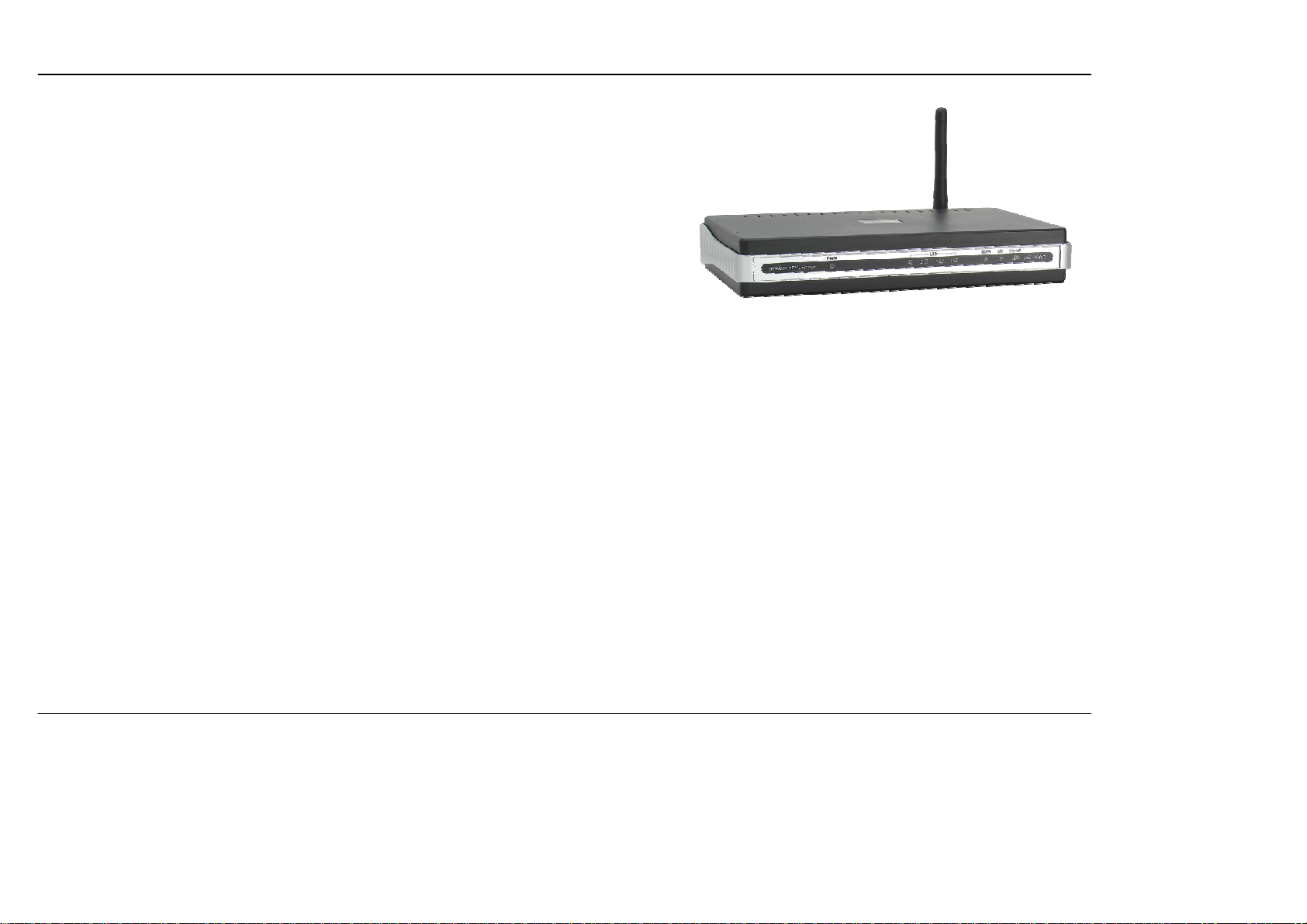
D-Link DSL-2640R User Manual 1
Page 5

Section 1 - Product Overview
11
Features
• PPP (Point-to-Point Protocol) Security – The DSL-2640R ADSL Router supports PAP (Password Authentication Protocol) and CHAP
(Challenge Handshake Authentication Protocol) for PPP connections. The Router also supports MSCHAP.
• DHCP Support – Dynamic Host Configuration Protocol automatically and dynamically assigns all LAN IP settings to each host on your
network. This eliminates the need to reconfigure every host whenever changes in network topology occur.
• Network Address Translation (NAT) – For small office environments, the DSL-2640R allows multiple users on the LAN to access the
Internet concurrently through a single Internet account. This provides Internet access to everyone in the office for the price of a single user.
NAT improves network security in effect by hiding the private network behind one global and visible IP address. NAT address mapping can
also be used to link two IP domains via a LAN-to-LAN connection.
• TCP/IP (T ransfer C ontrol Protocol/Internet Protocol) – The DSL-2640R supports TCP/IP protocol, the language used for the Internet. It is
compatible with access servers manufactured by major vendors.
• RIP-1/RIP-2 – The DSL-2640R supports both RIP-1 and RIP-2 exchanges with other routers. Using both versions lets the Router to
communicate with all RIP enabled devices.
• Static Routing – This allows you to select a data path to a particular network destination that will remain in the routing table and never “age
out”. If you wish to define a specific route that will always be used for data traffic from your LAN to a specific destination within your LAN (for
example to another router or a server) or outside your network (to an ISP defined default gateway for instance).
• Default Routing – This allows you to choose a default path for incoming data packets for which the destination address is unknown. This is
particularly useful when/if the Router functions as the sole connection to the Internet.
• Precise ATM Traffic Shaping – Traf fic shaping is a method of controlling the flow rate of ATM data cells. This function helps to establish the
Quality of Service for ATM data transfer.
• Full Network Management – The DSL-2640R incorporates SNMP (Simple Network Management Protocol) support for web-based
management and text-based network management.
• Easy Installation – The DSL-2640R uses a web-based graphical user interface program for convenient management access and easy set
up. Any common web browser software can be used to manage the Router.
D-Link DSL-2640R User Manual 2
Page 6
Section 1 - Product Overview
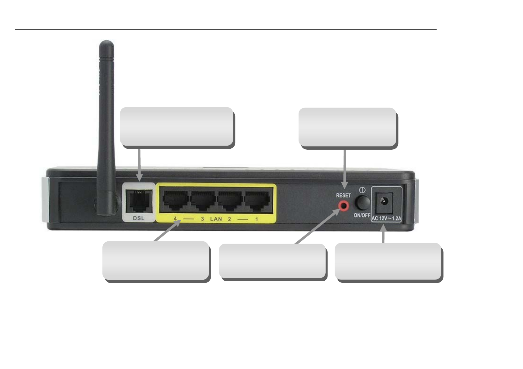
Hardware Overview
Connections
ADSL Port
Use the ADSL cable to connect to
the your telephone line (RJ-11 port)
Ethernet Ports
Use the Ethernet ports to connect
the Router to a computer or an
Ethernet LAN
D-Link DSL-2640R User Manual 3
Power Button
Push in to power-on the Router.
Push again to power-off the
Router
Reset Button
To manually reset, depress
button with the power on for at
least seven seconds
Power Insert
Use the adapter shipped with the
Router to connect to power
source
Page 7
Section 1 - Product Overview
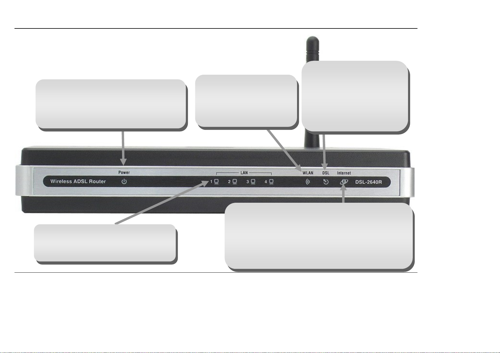
Power
Steady green light indicates the unit is powered on.
This remains dark when power is off. A red colored
Power LED indicates system failure.
Hardware Overview
LEDs
WLAN
Steady green lig ht indica te s a
wireless connection. A blinking
green light indicates activity on
the Wireless LAN interface.
DSL
A steady green light indic ates a
valid ADSL connection. This will
light after the ADSL negotiation
process has been settled. A
blinking green light indicates
activity on the WAN (ADSL)
interface.
Internet
A solid green light indicates the WAN IP address from IPCP or
DHCP and DSL is up or a static IP address is configured and
LAN
A solid green light indicates a valid link on
startup. This light will blink when there is activity
currently passing through the Ethernet port.
PPP negotiation has been su ccessf ully completed. If the
indicator blinks green, this means the Router is active. If the
Router power is off, this remains dark. A solid red light indicates
there is no DHCP response, no PPPoE response, PPPoE
authentication has failed, and/or there is no IP.
D-Link DSL-2640R User Manual 4
Page 8

Section 2 – Installation
Installation
This section will walk you through the installation process. Placement of the Wireless ADSL Router is very important. Do not place the Router in an
enclosed area such as a closet, cabinet, or in the attic or garage. Place the Wireless ADSL Router in a location where it can be easily connected to
Ethernet devices, the telephone line as well as to a power source.
Before You Begin
Please read and make sure you understand all the prerequisites for proper ins tallation of your new Router. Have all the necessary information and
equipment on hand before beginning the installation.
Installation Notes
In order to establish a connection to the Internet it will be necessary to provide information to the Router that will be stored in its memory. For some
users, only their account information (Username and Passwo rd) is required. For others, various parameters that control and define the Inte rnet
connection will be required. You can print out the two pages below and use the tables to l ist thi s informatio n. Th is way yo u have a hard copy of all
the information needed to setup the Router. If it is necessary to reconfigure the d evice, all the necessary information can be easily accesse d. Be
sure to keep this information safe and private.
Low Pass Filters
Since ADSL and telephone services share the same copper wiring to carry their respective signals, a filtering mechanism may be necessary to
avoid mutual interference. A low pass filter device can be installed for each telephone that shares the line with the ADSL line. These filters are easy
to install passiv e devices that connect to the ADSL device and/or telephone using standard telephone cable. Ask your service provider for more
information about the use of low pass filters with your installation.
Operating Systems
The DSL-2640R uses an HTML-based web interface for setup and management. The web configuration manager may be accessed using any
operating system capable of running web browser software, including Windows 98 SE, Windows ME, Windows 2000, Windows XP, and Windows
Vista.
D-Link DSL-2640R User Manual 5
Page 9

Section 2 – Installation
Web Browser
Any common web browser can be used to configure the Router using the web configuration management software. The program is designed to
work best with more recently released browsers such as Opera, Microsoft Internet Explorer® version 6.0, Netscape Navigator® version 6.2.3, or
later versions. The web browser must have JavaScript enabled. JavaScript is enabled by default on many browsers. Make sure JavaScript has not
been disabled by other software (such as virus protection or web user security packages) that may be running on your computer.
Ethernet Port (NIC Adapter)
Any computer that uses the Router must be able to connect to it through the Ethernet port on the Router. This connection is an Ethernet connection
and therefore requires that your computer be equipped with an Ethernet port as well. Most notebook computers are now sold with an Ethernet port
already installed. Likewise, most fully assembled desktop computers come with an Ethernet NIC adapter as standard equipment. If your computer
does not have an Ethernet port, you must install an Ethernet NIC adapter before you can use the Router. If you must install an adapter, follow the
installation instructions that come with the Ethernet NIC adapter.
Additional Software
It may be necessary to install software on your computer that enables the computer to access the Internet. Additional software must be installed if
you are using the device a simple bridge. For a bridged connection, the information needed to make and maintain the Internet connection is stored
on another computer or gateway device, not in the Router itself.
If your ADSL service is delivered through a PPPoE or PPPoA connection, the information needed to establish and maintain the Internet connection
can be stored in the Router. In this case, it is not necessary to install software on your computer. It may however be necessary to change some
settings in the device, including account information used to identify and verify the connection.
All connections to the Internet require a unique global IP address. For bridged connections, the global IP settings must reside in a TCP/IP enabled
device on the LAN side of the bridge, such as a PC, a server, a gateway device such as a router or similar firewall hardware. The IP address can be
assigned in a number of ways. Y our network service provider will give you instructions about any additional connection software or NIC
configuration that may be required.
Wireless LAN
Computers using the Wireless network can access the Internet or use the embedded 802.1g wireless access point. Wireless workstations must
have an 802.1g or 802.1b wireless network card installed to use the Wireless ADSL Router. In addition the workstations must be configured to
operate on the same channel and SSID as the Wireless ADSL Router. If wireless security is used, the wireless workstations must be properly
configured for the security settings used.
D-Link DSL-2640R User Manual 6
Page 10

Section 2 – Installation
Information you will need from your ADSL service
provider
Username
This is the Username used to log on to your ADSL service provider’s network. Your ADSL service provider uses this to identify your account.
Password
This is the Password used, in conjunction with the Username above, to log on to your ADSL service provider’s network. This is used to verify the
identity of your account.
WAN Setting / Connection Type
These settings describe the method your ADSL service provider uses to transport dat a betwee n the Internet and yo ur comput er. Most users will use
the default settings. You may need to specify one o f the following WAN Setting and Connection T y pe configura tions (Connecti on T y pe settings listed
in parenthesis):
• PPPoE/PPoA (PPPoE LLC, PPPoA LLC or PPPoA VC-Mux)
• Dynamic IP Address (1483 Bridged IP LLC, 1483 Bridged IP VC-Mux, 1483 Routed IP LLC(IPoA) or 1483 Routed IP VC-Mux)
• Static IP Address (1483 Bridged IP LLC, 1483 Bridged IP VC-Mux, 1483 Routed IP LLC(IPoA) or 1483 Routed IP VC-Mux)
• Bridge Mode (1483 Bridged IP LLC or 1483 Bridged IP VC Mux)
Modulation Type
ADSL uses various standardized modulation techniques to transmit data over the allotted signal frequencies. Some users may need to change the
type of modulation used for their service. The default DSL modulation (ADSL2+ Multi-Mode) used for the Router automatically detects all types of
ADSL, ADSL2, and ADSL2+ modulation.
Security Protocol
This is the method your ADSL service provider will use to verify your Username and Password wh en you log on to their network. Your Router
supports the PAP and CHAP protocols.
D-Link DSL-2640R User Manual 7
Page 11

Section 2 – Installation
VPI
Most users will not be required to change this setting. The Virtual Path Identifier (VPI) is used in conjunction with the Virtual Channel Identifier (VCI)
to identify the data path between your ADSL service provider’s network and your computer. If you are setting up the Router for multiple virtual
connections, you will need to configure the VPI and VCI as instructed by your ADSL service provider for the additional connections. This setting can
be changed in the WAN Settings window of the web management interface.
VCI
Most users will not be required to change this setting. The Virtual Channel Identifier (VCI) used in conjunction with the VPI to identify the data path
between your ADSL service provider’s network and your computer. If you are setting up the Router for multiple virtual connections, you wil l need to
configure the VPI and VCI as instructed by your ADSL service provider for the additional connections. This setting can be changed in the WAN
Settings window of the web management interface.
Information you will need about DSL-2640R
Username
This is the Username needed access the Router’s management interface. When you attempt to connect to the device through a web browser you
will be prompted to enter this Username. The default Username for the Router is “admin.” The user cannot change this.
Password
This is the Password you will be prompted to enter when you access the Router’s management interface. The default Password is “1234.” The user
may change this.
LAN IP addresses for the DSL-2640R
This is the IP address you will enter into the Address field of your web browser to access the Router’s configuration graphical user interface (GUI)
using a web browser. The default IP address is 192.168.1.1. This may be changed to suit any IP address scheme the user desires. This address will
be the base IP address used for DHCP service on the LAN when DHCP is enabled.
LAN Subnet Mask for the DSL-2640R
This is the subnet mask used by the DSL-2640R, and will be used throughout your LAN. The default subnet mask is 255.255.255.0. This can be
changed later.
D-Link DSL-2640R User Manual 8
Page 12

Section 2 – Installation
Information you will need about your LAN or computer:
Ethernet NIC
If your computer has an Ethernet NIC, you can connect the DSL-2640R to this Ethernet port using an Ethernet cable. You can also use the Ethernet
ports on the DSL-2640R to connect to other computer or Ethernet devices.
DHCP Client st atus
Your DSL-2640R ADSL Router is configured, by default, to be a DHCP server. This means that it can assign an IP address, subnet mask, and a
default gateway address to computers on your LAN. The default range of IP addresses the DSL-2640R will assign are from 192.168.1.2 to
192.168.1.254. Your computer (or computers) needs to be configured to obtain an IP address automatically (that is, they need to be configured as
DHCP clients.)
It is recommended that you collect and record this information here, or in some other secure place, in case you have to re-configure your ADSL
connection in the future.
Once you have the above information, you are ready to setup and configure your DSL-2640R ADSL Router.
Device Installation
The Wireless ADSL Router maintains three separate interfaces, an ADSL, an Ethernet, and a Wireless LAN interface. Place the Wireless ADSL
Router in a location where it can be easily connected to Ethernet devices, the telephone line as well as to a power source.
The Router can be placed on a shelf or desktop, ideally you should be able to see the LED indicators on the front if you need to view them for
troubleshooting.
D-Link DSL-2640R User Manual 9
Page 13

Section 2 – Installation
Power on Router
The Router must be used with the power adapter included with the device.
1. Connect the power adapter to the Power Input (12V AC 1.2A) on the back panel of the Wireless ADSL Router and plug the other end of the
power adapter to a wall outlet or power strip.
2. Push the Power Button toggle the power on.
3. The Power LED on the front panel will shine bright green to indicate the device is powered on.
4. If the Ethernet port is connected to a working device, check the LAN LED indicator to make sure the connection is valid. The Wireless ADSL
Router will attempt to establish the ADSL connection, if the ADSL line is connected and the Wireless ADSL Router is properly configured the
ADSL LED will light up after several seconds. If this is the first time installing the device, some settings may need to be changed before the
Wireless ADSL Router can establish a conne ction.
Factory Reset Button
The Router may be reset to the orig inal f actory d efault setting s by usin g a ball point or papercl ip to gen tly push down the reset butt on in th e follo wing
sequence:
1. Press and hold the reset button while the device is powered off.
2. Turn on the power.
3. Wait for 5~8 seconds and then release the reset button.
Remember that this will wipe out any settings stored in flash memory including user account information and LAN IP settings. The device settings
will be restored to the factory default IP address 192.168.1.1 and the subnet mask is 255.255.255.0, the default management Username is “admin”
and the default Password is “admin.”
D-Link DSL-2640R User Manual 10
Page 14

Section 2 – Installation
Network Connections
Connect ADSL Line
Use the ADSL cable included with the Router to connect it to a telephone wall socket or receptacle. Plug one end of the cable into the ADS L port
(RJ-1 1 recept acle) on the rear panel of the Router and insert the other end into the RJ-11 wall socket. If you are using a low pass filter device, follow
the instructions included with the device or given to you by your service provider. The ADSL connection represents the WAN interface, the
connection to the Internet. It is the physical link to the service provider’s network backbone and ultimately to the Internet.
Connect Router to Ethernet
The Router may be connected to a single computer or Ethernet device through the 10BASE-TX Ethernet port on the rear panel. Any connection to
an Ethernet concentrating device such as a switch or hub must operate at a speed of 10/100 Mbps only. When connecting the Router to any
Ethernet device that is capable of operating at speeds higher than 10Mbps, be sure that the device has auto-negotiation (NWay) enabled for the
connecting port. Use standard twisted-pair cable with RJ-45 connectors. The RJ-45 port on the Router is a crossed port (MDI-X). Follow standard
Ethernet guidelines when deciding what type of cable to use to make this connection. When connecting the Router directly to a PC or server use a
normal straight-through cable. You should use a crossed cable when connecting the Router to a normal (MDI-X) port on a switch or hub. Use a
normal straight-through cable when connecting it to an uplink (MDI-II) port on a hub or switch. The rules governing Ethernet cable lengths apply to
the LAN to Router connection. Be sure that the cable connecting the LAN to the Router does not exceed 100 meters.
Hub or Switch to Router Connection
Connect the Router to an uplink port (MDI-II) on an Ethernet hub or switch with a straight-through cable. If you wish to reserve the uplink port on the
switch or hub for another device, connect to any on the other MDI-X ports (1x, 2x, etc.) with a crossed cable.
Computer to Router Connection
You can connect the Router directly to a 10/100BASE-TX Ethernet adapter card (NIC) installed on a PC using the Ethernet cable provided.
Wireless Connection to Router
The Router’s embedded 802.11g wireless access point should be configured to suit the local wireless network. All 802.11g or 802.11b devices that
associate with the Router’s wireless access point must have the same SSID and channel. If wireless security is used, the wireless clients must be
configured with the correct security inf ormation t o use the R outer. More information on config uring t he w ireless sett ings is found later in this manual.
D-Link DSL-2640R User Manual 11
Page 15

Section 3 – Configuration
Setup
This section will show you how to set up and configure your ne w D-Link Router using the Web-based configuration utility.
Web-based Configuration Utility
Connect to the Router
To configure the WAN connection used by the Router it is first necessary to commu nica te with the Router through its management interface, which
is HTML-based and can be accessed using a web browser. The easiest way to make sure your computer has the correct IP settings is to configure
it to use the DHCP server in the Router. The next section describes how to change the IP configuration for a computer running a Windows operating
system to be a DHCP client.
To access the configuration utility, open a web-browser such as Internet
Explorer and enter the IP address of the router (192.168.1.1).
Type “admin” for the User Name and “1234” in the Password field. If you
get a Page Cannot be Displayed error, please refer to the
Troubleshooting section for assistance.
D-Link DSL-2640R User Manual 12
Page 16

Section 3 – Configuration
Configure the Router
When you successfully connect to the web manager, the main Status
menu displays a summary of the current state of the Etherne t LAN and
WAN networks. This menu can be accessed at any time using the St atus
hyperlink.
All configuration and management of the Router is done using the
web-based management interface pictured in the example.
To access the various configuration menus, open the directories listed in
the left panel of the menu, Quick Start, Interface Setup, Advanced
Setup, Access Management, Maintenance, and Status.
The Quick Start Wizard allows you to configure the basic settings for the
WAN (Internet) and Ethernet LAN (including DHCP) settings.
D-Link DSL-2640R User Manual 13
Page 17

Section 3 – Configuration
Quick Start
This chapter is concerned with using your computer to configure the WAN connection. The following chapter describes the various windows used to
configure and monitor the Router including how to change IP settings and DHCP server setup.
Quick Start
To use the Quick Start Wizard, click the RUN WIZARD button and follow
the instructions in the pop-up window that appears.
The initial window summarizes the setup process. Click the Next button to
proceed. You may stop using the Quick Start Wizard at any time by
clicking the Exit button. If you exit the wizard you will return to the main
Quick Start window without saving any of the settings changed during the
process.
Quick Start Wizard – Opening Window
The first pop-up window of the Quick Start Wizard lists the basic steps in
the process. These steps are as follows:
1. Set your new password
2. Choose your time zone
3. Set your Internet connection
4. Re-start your ADSL router
Click Next to continue.
D-Link DSL-2640R User Manual 14
Page 18

Section 3 – Configuration
Quick Start Wizard – Set a Password
If you want to change the administrator account password, enter a new
password in the first text box, re-type it in the second text box, and click
Next. If you wish to return to the previous window during the setup
process, click the Back button.
Quick Start Wizard - Choose Time Zone
Choose the time zone you are in from the pull-down menu and click Next.
This sets the system time used for the Router. If you wish to return to the
previous window during the setup process, click the Back button.
D-Link DSL-2640R User Manual 15
Page 19

Section 3 – Configuration
Quick Start Wizard – Select ISP Connection Type
Now select the Connection Type used for the Internet connection. Your
ISP has given this information to you. The connection types available are
Dynamic IP Address, Static IP Address, PPPoE/PP P oA, and Bridge
Mode. Each connection type has different settings that are configured in
the next Quick Start Wizard window.
Select the Connecti on Type specific to your service and click Next to go
to the next Quick Start Wizard window. Follow the instructions below for
the type of connection you have selected.
Quick Start Wizard - For PPPoE/PPPoA connections:
1. Type in the Username and Password used to identify and verify
your account to the ISP.
2. If you are instructed to change the VPI or VCI number, type in the
correct setting in the available entry fields. Most users will not need
to change these settings. The Internet connection cannot function if
these values are incorrect.
3. Select the specific Connection Type from the drop-down menu.
The available PPP connection and encapsulation types a r e PPPoE
LLC, PPPoE VC-Mux, PPPoA LLC, and PPPoA VC-Mux.
4. Click Next to go to the next window and complete the Quick Start
Wizard.
D-Link DSL-2640R User Manual 16
Page 20

Section 3 – Configuration
Quick Start Wizard - For Dy namic IP Address connections:
1. If you are instructed to change the VPI or VCI number, type in the
correct setting in the available entry fields. Most users will not need
to change these settings. The Internet connection cannot function if
these values are incorrect.
2. Select the specific Connection Type from the drop-down menu.
The available Dynamic IP Address connection and encapsulation
types are 1483 Bridged IP LLC, 1483 Bridged IP VC-Mux, 1483
Routed IP LLC (IPOA), and 1483 Routed IP VC-Mux.
3. Click Next to go to the next pop-up window and complete the Quick
Start Wizard.
Quick Start Wizard - For Static IP Address connections:
1. If you are instructed to change the VPI or VCI number, type in the
correct setting in the available entry fields. Most users will not need
to change these settings. The Internet connection cannot function if
these values are incorrect.
2. Change the IP Addres s, Subnet Mask, and ISP Gateway as
instructed by your ISP.
3. Select the specific Connection Type from the drop-down menu.
The available Static IP Address connection and encapsulation
types are 1483 Bridged IP LLC, 1483 Bridged IP VC-Mux, 1483
Routed IP LLC (IPoA), and 1483 Routed IP VC-Mux.
4. Click Next to go to the next window and complete the Quick Start
Wizard.
D-Link DSL-2640R User Manual 17
Page 21

Section 3 – Configuration
Quick Start Wizard - For Bridge Mode connections:
1. If you are instructed to change the VPI or VCI number, type in the
correct setting in the available entry fields. Most users will not need
to change these settings. The Internet connection cannot function if
these values are incorrect.
2. Select the specific Connection Type from the drop-down menu.
The available Bridge Mode connection and encapsulation types
are 1483 Bridged IP LLC and 1483 Bridged IP VC-Mux.
3. Click Next to go to the next window and complete the Quick Start
Wizard.
Quick Start Wizard - Finish
Finally, if you are satisfied that you have entered all the necessary
information correctly, click the Next button to save the new configuration
settings. If you need to change settings from a previous window, click the
Back button.
Click the Close button to complete the Quick Start setup procedure.
D-Link DSL-2640R User Manual 18
Page 22

Section 3 – Configuration
Interface Setup
To configure the Router’s basic Internet and LAN configuration settings without running the Quick Start Wizard, click on the Interface Setup link in
the Wireless ADSL Router’s opening page.
This window is also used to configure the Router for multiple virtual connections (Multiple PVCs).
Use the Virtual Circuit drop-down menu to display up to eight
configurable profiles for the Internet interface. If you do not intend to use
more than a single virtual connection (most users), you can use the
default setting (PVC0). If you are using multiple connections, use the
Virtual Circuit drop-down menu to access the Interface Setup window
for each desired connection. To change the settings for any profile in the
list, use the Virtual Circuit drop-down menu to display individual profiles
or click the PVCs Summary button to display the following summary of all
the profiles for the Internet interface.
D-Link DSL-2640R User Manual 19
Page 23

Section 3 – Configuration
PPPoE/PPPoA
To set up a PPPoE or PPPoA connection:
1. Choose the PPPoA/PPPoE option under ISP in the Encapsulation
section.
2. Most users will not need to change ATM settings in the ATM VC sec tion.
If this is the first time you are setting up the ADSL connection it is
recommended that you leave the ATM QoS type and associated Cell
Rate settings at the default values until you have established the
connection and verified that your ISP supports ATM for your ADSL
account. However, if you are instructed to change the VPI or VCI values,
type in the values assigned for your account. Leave the Virtual Circuit
and Status settings at the defaults (Pcv0 and Activated) values for now.
These can be used later if you are configuring multiple virtual circuits for
your ADSL service.
3. Most users will not need to change QoS settings. If this is the first time
you are setting up the ADSL connection it is recommended that you leave
the settings at the default values until you have established the
connection. Please see the table on ATM QoS in the next section of this
manual for further information.
4. In the PPPoE/PPPoA section, type the Username and Password used
for your ADSL account. A typical User Name will be in the form
user1234@isp.co.uk
may have selected it when you set up the account with your ISP.
5. Choose the Encapsulation setting from the pull-down menu. This
defines the encapsulation method used for your ADSL service. The
available options are PPPoE LLC, PPPoE VC-Mux, PPPoA LLC, and
PPPoA VC-Mux. If you have not been provided specific information for
this section, leave the default setting.
. Your ISP may assign the Password to you or you
D-Link DSL-2640R User Manual 20
Follow the instructions to configure the Router to use a PPPoA or PPPoE for the
Internet connection. Make sure you have all the necessary information before you
configure the Internet (W AN) connection.
Page 24

Section 3 – Configuration
6. Activate or Deactivate the Bridge Interface.
7. Select the correct Connection value in the Connection Setting section.
If your account is time-based, that is, if your connection fees are based
on the amount of time the Router is actively connected to the Internet,
select the Connect On-Demand option and enter an appropriate idle
timeout in the entry field provided. If your account is billed with a flat fee
regardless of how much time the Router is connected, select the Always
On option. This will maintain the PPP session as long as the Router is
powered on.
8. The TCP MSS option can be used when excessive fragmentation of
packets effect download speeds. Enter a value for the Maximum
Segment Size to avoid fragmenting TCP packets
9. Typically the globally IP settings (i.e. IP address for the WAN interface)
for a PPPoA or PPPoA connection will use Dynamic IP assignment from
the ISP. Some accounts may be assigned a specific global IP address. If
you have been give an IP address for you PPPoE/PPPoA connection,
select the Static option from the Get IP Address pull-down menu and
enter the Static IP Address, IP Subnet M ask, and Gateway information.
10. NAT should remain Enabled. If you disable NAT, you will not be able to
use more than one computer for Internet connections. NAT is Enabled
and Disabled system-wide, therefore if you are using multiple virtual
connections, NAT will disabled on all connections.
11. Turn on the Default Route feature if you want to use the Router as the
default route to the Internet for your LAN. Whenever a computer on the
LAN attempts to access the Internet, the Router becomes the Internet
gateway to the computer. If you have an alternative route for Internet
traffic you may turn this off without effecting the Router’s connection.
12. Leave the TCP MTU Option value at the default setting unless you have
specific reasons to change this.
13. Select the desired Dynamic Route from RIP1, RIP2-B, or RIP2-M. Next,
set the Direction to Both, IN Only, OUT Only, or None.
14. The Multicast feature is Disabled by default. Toggle between IGMP v1
and IGMP v2.
15. When you are satisfied that all the Internet settings are configured
correctly, click on the SAVE button.
When PPPoE or PPPoA is used, the Router becomes the PPP client, that is, all the
software needed to est ab lish and maintain the connection is located on the Router.
ISPs frequently require PPP client software to be installed on workstations. If any
computers have PPP client software installed on them, this software must be
removed or at least disabled before the computers are able to connect to the
Internet through the Router. If you are required to provide a User Name and
Password every time you access the Internet, your computer may have PPP client
software installed on it.
D-Link DSL-2640R User Manual 21
Page 25

Section 3 – Configuration
Dynamic IP Address
To configure a Dynamic IP Address WAN connection, follow these steps:
1. Choose the Connection Type from the drop- down menu. This defines both the
connection protocol and encapsulation method used for your ADSL service. The
available options are 1483 Bridged IP LLC and 1483 Bridged IP VC-Mux. If you
have not been provided specific informa tion for the Connection Type s etting,
leave the default setting.
2. Some ISPs record the unique MAC Addr es s of your computer’s Ethernet
adapter when you first access their network. This can prevent the Router (which
has a different MAC addre ss) from being allowed access to the ISPs network
(and the Internet). To clone the MAC address of your computer’s Ethernet
adapter, cli ck the Copy Your P C’s MAC Address but ton.
3. If you are instructed to change the VPI or VCI values, type in the values
assigned for your account.
4. When you are satisfied that all the WAN settings are configured correctly, click
the Apply Settings button. This will save the settings and reboot the Router to
let your changes take effect.
5. Upon restarting, the Router should automatically establish the WAN connection.
If it does not, click the Connect button at the bottom of this window.
6. Turn on the Default Route feature if you want to use the Router as the default
route to the Internet for your LAN. Whenever a comp uter on the LAN a tte mpts to
access the Internet, the Router becomes the Internet gateway to the computer. If
you have an alternative route for Internet traffic you may turn this off without
effecting the Router’s connection.
7. Leave the TCP MTU Optio n value at the default setting un less you have specif ic
reasons to change this.
8. Select the desired Dynamic Route from RIP1, RIP2-B, or RIP2-M. Next, set the
Direction to Both, IN Only, OUT Only, or None.
9. The Multicast feature is Disabled by default. Toggle between IGMP v1 and
IGMP v2.
10. When you are satisfied that all the Internet settings are configured correctly, click
on the SAVE button.
A Dynamic IP Address connection configures the Router to automatically obtain its
global IP address from a DHCP server on the ISP’s network. The service provider
assigns a global IP address from a pool of addresses available to the service
provider. Typically the IP address assigned has a long lease time, so it will likely be
the same address each time the Router requests an IP address.
D-Link DSL-2640R User Manual 22
Page 26

Section 3 – Configuration
Static IP Address
To configure a Static IP type connection for the WAN, follow these steps:
1. Choose the Static IP Address option under ISP in the Encapsulation section.
2. The settings in the ATM VC section at the top of the window should not be changed unless
you have been instructed to change them. However, if you are instructed to change the VPI
or VCI values, type in the values assigned for your account. Leave the Virtual Circuit and
Status settings at the defaults (Pcv0 and Activated) values for now. This can be used later
if you are configuring multiple virtual circuits for your ADSL service.
3. Most users will not need to change QoS settings. If this is the first time you are setting up
the ADSL connection it is recommended that you leave the settings at the default values
until you have established the connection. Please see the table on ATM QoS that directly
follows the PPPoA/PPPoE section of this manual for further information.
4. In the Static IP section, choose the Encapsulation setting from the pull-down menu. This
defines the encapsulation method used for your ADSL service. The availa ble opt ions are
1483 Bridged IP LLC, 1483 Bridged IP VC-Mux, 1483 Routed IP LLC (IPOA), and 1483
Routed IP VC-Mux. If you have not been provided specific information for this section,
leave the default setting.
5. Change the Static IP Address, IP Subnet Mask, and Gateway IP address as instructed
by your ISP. These are the global IP settings for the Internet (WAN) interface. This is the
“visible” IP address of your account. Your ISP should have provided these IP settings to
you.
6. NAT should remain enabled. If you disable NAT, you will not be able to use more than one
computer for Internet connections. NAT is enabled and disabled system-wide, therefore if
you are using multiple virtual connections, NAT will disabled on all connections.
7. Turn on the Default Route feature if you want to use the Rout er as the default route to the
Internet for your LAN. Whenever a compute r on the LAN attempts to access the Internet,
the Router becomes the Internet gateway to the computer. If you have an alternative route
for Internet traffic you may turn this off without effecting the Router’s connection.
8. Leave the TCP MTU Option value at the default setting unless you have specific reasons
to change this.
9. Select the desired Dynamic Route from RIP1, RIP2-B, or RIP2-M. Next, set the Direction
to Both,
10. The Multicast feature is Disabled by default. Toggle between IGMP v1 and IGMP v2.
11. When you are satisfied that all the Internet settings are configured correctly, click o n the
SAVE button.
IN Only, OUT Only, or None.
When the Router is configured to use Static IP Address assignment for
the Internet (WAN) connection, you must manually assign a global IP
Address, Subnet Mask and Gateway IP Address used for the WAN
connection. Follow the instructio n below to configure the Router to use
Static IP Address assignment for the WAN connection.
D-Link DSL-2640R User Manual 23
Page 27

Section 3 – Configuration
Bridge Mode
Follow the instructions below to configure a Bridged connection for the Internet interface.
1. Choose the Bridge Mode option under ISP in the Encapsulation section.
2. The settings in the ATM VC section at the top of the window should not be
changed unless you have been instructed to change them. However, if you are
instructed to change the VPI or VCI values, type in the values assigned for your
account. Leave the Virtual Circuit and Status settings at the defaults (Pcv0 and
Activated) values for now. This can be used later if you are configuring multiple
virtual circuits for your ADSL service.
3. Most users will not need to change QoS settings. If this is the first time you are
setting up the ADSL connection, it is recommended that you leave the settings at
the default values until you have established the connection. Please see the
table on ATM QoS that directly follows the PPPoA/PPPoE section of this manual
for further information.
4. In the Bridge Mode section, choose the Encapsulation setting from the
pull-down menu. This defines the encapsulation method used for your ADSL
service. The available options are 1483 Bridged IP LLC and 1483 Bridged IP
VC-Mux. If you have not been provided specific informa tion for this section,
leave the default setting.
5. When you are satisfied that all the Internet settings are configured correctly, click
on the SAVE button.
For Bridged connections it will be necessary for most users to install additional
software on any computer that will the Router for Internet access. The additional
software is used for the purpose of identifying and verifying your account, and then
granting Internet access to the computer requesting the connection. The connection
software requires the user t o enter the User Na me and Passw ord for th e ISP a ccount .
This information is stored on the computer, not in the Router.
D-Link DSL-2640R User Manual 24
Page 28

Section 3 – Configuration
LAN Setup
To access the LAN window, click the LAN button in the Interface Setup directory.
You can configure the LAN IP address to suit your preference. Many users
will find it convenient to use the default settings together with DHCP
service to manage the IP settings for their private network. The IP address
of the Router is the base address used for DHCP. In order to use the
Router for DHCP on your LAN, the IP address pool used for DHCP must
be compatible with the IP address of the Router. The IP addresses
available in the DHCP IP address pool will change automatically if you
change the IP address of the Router.
To configure the LAN IP address, type in the desired values and click the
SAVE button. Your web browser should automatically be redirected to the
new IP address. You will b e asked to login to the Router’s web manager
again.
The DHCP server is enabled by default for the Router’s Ethernet LAN
interface. DHCP service will supply IP settings to workstations configured
to automatically obtain IP s ettings that a re connect ed to the Route r though
the Ethernet port. When the Router is used for DHCP it becomes the
default gateway for DHCP client connected to it. Keep in mind that if you
change the IP address of the Router the ra nge of IP ad dresse s in the poo l
used for DHCP on the LAN will also be changed. The IP address pool can
be up to 253 IP addresses.
The three options for DHCP service are as follows:
Use the Router as a DHCP server for your LAN.
Disable DHCP service an d manually configure IP settings for
workstations.
Use DHCP service provided by your ISP.
D-Link DSL-2640R User Manual 25
Page 29

Section 3 – Configuration
Use the Router for DHCP
To use the built-in DHCP server , click t he DHCP radio button to Enabled if it has not already selected. The IP Address Pool settings can be adjusted.
The Starting IP Address is the lowest available IP address (default = 192.168.1.2). If you change the IP address of the Router, this will change
automatically to be 1 more that the IP address of the Router. Type in the Lease Time in the entry field provided. This is the amount of time in
seconds that a workstation is allowed to reserve an IP address in the pool if the workstation is disconnected from the network or powered off.
You may also configure DNS settings for the LAN when using the Router in DHCP mode. Toggle the DNS Relay setting to Use User Discovered
DNS Server Only from Use Auto Discovered DNS Server Only and enter the IP addresses for the Primary DNS Server and Secondary DNS
Server in the field provided. The manually configured DNS settings will be supplied to clients that are configured to request them from the Router.
Disable the DHCP Server
To disable DHCP, select the Disabled option and click on the SAVE button. Choosing this option requires that workstations on the local network
must be configured manually or use another DHCP server to obtain IP settings.
If you configure IP settings manually, make sure to use IP addresses in the subnet of the Router. Y ou will need to use the Router’s IP address as the
Default Gateway for workstations in order to provide Internet access.
Use DHCP Relay
To use DHCP service from your ISP or another DHCP server, select the Relay option and type the DHCP Server IP for Relay Agent address in the
space provided. Click SA VE to begin DHCP relay from the ISP.
D-Link DSL-2640R User Manual 26
Page 30

Section 3 – Configuration
Wireless Setup
The two essential settings for wireless LAN operation are the SSID and
Channel Number. The SSID (Service Set Identifier) is used to identify a
group of wireless LAN components. The SSID can be broadcast in order
to allow properly configured wireless stations to learn the SSID and join
the group.
Wireless LAN is enabled by default on the Router. If the wireless access
point has been previously disabled you can enable 802.11g Wireless LAN
operation by selecting the Activated option for Wireless LAN and
continue to configure basic settings. Click the SAVE button to begin
wireless LAN function with the settings as configured. It is not necessary
to reboot the Router.
D-Link DSL-2640R User Manual 27
 Loading...