

Page 1
Building Networks for People
Policy Manager
User Manual
DUA-2000
Ver. 1.0
Business Wireless Solution
Page 2
D-Link DUA-2000 Policy Manager User Manual
Information in this document is subject to change without notice.
© 2016 D-Link Corporation. All rights reserved.
Reproduction in any manner whatsoever without the written permission of D-Link Corporation is strictly
forbidden.
Trademarks used in this text: D-Link and the D-Lin k logo a re trad emarks of D-Link Corporation; Microsoft and
Windows are registered trademarks of Microsoft Corporation.
Other trademarks and trade names may be used in this document to refer to either the entities claiming the
marks and names or their products. D-Link Corporation disclaims any proprietary interest in trademarks and
trade names other than its own.
FCC Warning
This equipment has been tested and found to comply with the limits for a Class A digit al device, pursuant to
Part 15 of the FCC Rules. These limits are designed to provide reasonable protection against harmful
interference when the equipment is operated in a commercial environment. This equipment generates, uses,
and can radiate radio frequency energy and, if not installed and used in accordance with this user’s guide, may
cause harmful interference to radio communications. Operation of this equipment in a residential area is likely
to cause harmful interference in which case the user will be required to correct the interference at his own
expense.
CE Mark Warning
This is a Class A product. In a domestic environment, this product may cause radio interference in which case
the user may be required to take adequate measures.
Warnung!
Dies ist ein Produkt der Klasse A. Im Wohnbereich kann dieses Produkt Funkstoerungen verursachen. In
diesem Fall kann vom Benutzer verlangt werden, angemessene Massnahmen zu ergreifen.
Precaución!
Este es un producto de Clase A. En un entorno doméstico, puede causar interferencias de radio, en cuyo case,
puede requerirse al usuario para que adopte las medidas adecuadas.
Attention!
Ceci est un produit de classe A. Dans un environnement domestique, ce produit pourrait causer des
interférences radio, auquel cas l`utilisateur devrait prendre les mesures adéquates.
Attenzione!
Il presente prodotto appartiene alla classe A. Se utilizzato in ambiente domestico il prodotto può causare
interferenze radio, nel cui caso è possibile che l`utente debba assumere provvedimenti adeguati.
VCCI Warning
May, 2016
ii
Page 3

D-Link DUA-2000 Policy Manager User Manual
Table of Contents
Table of Contents ................................................................................................................................................................. iii
1. Introduction ................................................................................................................................................................... 1
Audience ............................................................................................................................................................................ 1
Other Documentation ......................................................................................................................................................... 1
Conventions ....................................................................................................................................................................... 1
Notes, Notices, and Cautions ............................................................................................................................................ 2
2. Product Introduction ..................................................................................................................................................... 3
3. Hardware Installation .................................................................................................................................................... 4
Step 1: Unpacking .............................................................................................................................................................. 4
Packing Contents .......................................................................................................................................................... 4
Step 2: Server Installation .................................................................................................................................................. 4
Rack Installation ........................................................................................................................................................... 4
Step 3: Powering the Device .............................................................................................................................................. 4
4. Connecting to the Device ............................................................................................................................................. 5
Configuring the Network .................................................................................................................................................... 5
Logging on to the Web User Interface ............................................................................................................................... 5
Changing the Default IP Address ...................................................................................................................................... 6
5. System Overview........................................................................................................................................................... 7
6. Network Configuration Example .................................................................................................................................. 9
Network Requirements ...................................................................................................................................................... 9
Network Topology ............................................................................................................................................................ 10
Network Configuration ..................................................................................................................................................... 11
Wireless Controller ..................................................................................................................................................... 11
Poli cy Manager ........................................................................................................................................................... 11
Network Environment ................................................................................................................................................. 12
7. Status & Monitor.......................................................................................................................................................... 13
Dashboard........................................................................................................................................................................ 13
Dashboard .................................................................................................................................................................. 13
Network ............................................................................................................................................................................ 14
Interface Utilization ..................................................................................................................................................... 14
System ............................................................................................................................................................................. 14
Device Status .............................................................................................................................................................. 14
Logs ............................................................................................................................................................................ 15
8. Network ........................................................................................................................................................................ 17
Device .............................................................................................................................................................................. 17
IP Interface.................................................................................................................................................................. 17
IP Interface ............................................................................................................................................................... 17
Port Trunking Advance Setting ................................................................................................................................ 19
RADIUS Client ............................................................................................................................................................ 20
Add RADIUS Server Client ...................................................................................................................................... 21
Identity Domain ................................................................................................................................................................ 22
Identity Domain ........................................................................................................................................................... 22
Add Identity / Domain ............................................................................................................................................... 23
External Server ................................................................................................................................................................ 24
LDAP ........................................................................................................................................................................... 24
AD ............................................................................................................................................................................... 25
POP3 .......................................................................................................................................................................... 27
iii
Page 4

D-Link DUA-2000 Policy Manager User Manual
RADIUS ...................................................................................................................................................................... 28
9. Policy & Object ............................................................................................................................................................ 31
Policy Rule ....................................................................................................................................................................... 31
Rule ............................................................................................................................................................................. 31
Add Policy Rule ........................................................................................................................................................ 32
Client ................................................................................................................................................................................ 34
User Database ............................................................................................................................................................ 34
Group ....................................................................................................................................................................... 34
Account .................................................................................................................................................................... 36
Device Database ........................................................................................................................................................ 38
Property Group ......................................................................................................................................................... 38
Device ...................................................................................................................................................................... 39
Endpoint ........................................................................................................................................................................... 42
Location Profile ........................................................................................................................................................... 42
Location Profile ........................................................................................................................................................ 42
Endpoint List ............................................................................................................................................................ 43
Endpoint to Location Profile ..................................................................................................................................... 46
Authorization .................................................................................................................................................................... 47
Authorization Profile .................................................................................................................................................... 47
Authorization Profile ................................................................................................................................................. 47
ACL Profile ............................................................................................................................................................... 49
ACL Rule .................................................................................................................................................................. 51
Schedule .......................................................................................................................................................................... 54
Schedule Profile .......................................................................................................................................................... 54
Add Schedule Profile ................................................................................................................................................ 55
10. Maintenance ................................................................................................................................................................. 57
Administration .................................................................................................................................................................. 57
System Information ..................................................................................................................................................... 57
Change Password ...................................................................................................................................................... 58
System Account .......................................................................................................................................................... 58
Date and Time ............................................................................................................................................................ 60
Session ....................................................................................................................................................................... 62
Management .................................................................................................................................................................... 63
SNMP .......................................................................................................................................................................... 63
SNMP v3 User ......................................................................................................................................................... 63
SNMP Traps ............................................................................................................................................................. 65
SNMP Host List ........................................................................................................................................................ 66
Access Control List .................................................................................................................................................. 68
SNMP Community .................................................................................................................................................... 69
Telnet / SSH................................................................................................................................................................ 71
Web Server Configuration .......................................................................................................................................... 73
DDP ............................................................................................................................................................................ 74
System ............................................................................................................................................................................. 75
Firmware Upgrade ...................................................................................................................................................... 75
Firmware Info ........................................................................................................................................................... 75
Firmware Upgrade ................................................................................................................................................... 76
Backup / Restore System ........................................................................................................................................... 78
iv
Page 5

D-Link DUA-2000 Policy Manager User Manual
Backup System ........................................................................................................................................................ 78
Restore System ........................................................................................................................................................ 79
Reboot ........................................................................................................................................................................ 80
HA ............................................................................................................................................................................... 80
Logs ................................................................................................................................................................................. 82
Syslog Server ............................................................................................................................................................. 82
System Logs ............................................................................................................................................................... 83
Alert ............................................................................................................................................................................. 84
Email Alert ................................................................................................................................................................ 84
Alert Type ................................................................................................................................................................. 86
Utilities .............................................................................................................................................................................. 87
Logo Setting ................................................................................................................................................................ 87
Ping ............................................................................................................................................................................. 88
11. Appendix A - Technical Specifications ..................................................................................................................... 89
Capacity ........................................................................................................................................................................... 89
Hardware Specification .................................................................................................................................................... 89
Processor and System Memory.................................................................................................................................. 89
I/O Interface ................................................................................................................................................................ 89
Physical & Environment ................................................................................................................................................... 89
12. Appendix B – Rack Mount Instructions .................................................................................................................... 90
v
Page 6

D-Link DUA-2000 Policy Manager User Manual
1
1. Introduction
The manual is organized by the menu layout on the Policy Manager.
Audience
This reference manual is intended for network administrators and other IT networking
professionals responsible for managing the Policy Manager using the Web User Interface
(Web UI). Alternative management interfaces, such as the Command Line Interface (CLI)
are also available but not documented in this manual. This manual is written in a way that
assumes that you already have the experience and knowledge of modern networking
principles.
Other Documentation
The documents below are a further source of information in regards to configuring and
troubleshooting the DUA-2000. All the documents are available either from the CD, bundled
with the Policy Manager, or from the D-Link website. Other documents related to the device
are:
• Quick Installation Guide
Conventions
Convention Description
Boldface Font
Indicates a button, a toolbar icon, menu, or menu item. For
example: Open the File menu and choose Cancel. Used for
emphasis. May also indicate system messages or prompts
appearing on screen. For example: You have mail. Bold font
is also used to represent filenames, program names and
commands. For example: use the copy command.
Initial capital letter Indicates a window name. Names of keys on the keyboard
have initial capitals. For example: Click Enter.
Menu Name > Menu
Option
Indicates the menu structure. Device > Port > Po rt
Properties means the Port Properties menu option under
the Port menu option that is located under the Device menu.
Blue Courier Font
This convention is used to represent an example of a screen
console display including example entries of CLI command
input with the corresponding output.
Page 7

D-Link DUA-2000 Policy Manager User Manual
2
Notes, Notices, and Cautions
Below are examples of the three types of indicators used in this manual. When administering
the Policy Manager using the information in this document, you should pay special attention
to these indicators. Each example below provides an explanatory remark regarding each
type of indicator.
NOTE: A note indicates important information that helps you make better use of
your device.
NOTICE: A notice indicates either potential damage to hardware or loss of data
and tells you how to avoid the problem.
CAUTION: A caution indicates a potential for property damage, personal injury,
or death.
Page 8

D-Link DUA-2000 Policy Manager User Manual
3
2. Product Introduction
The trend of Bring Your Own Device (BYOD) is a new challenge for network administrators
and managers. Many companies that allow employees to use their own devices expect to
see improvements in performance and productivity, however BYOD brings its own
challenges to do with network security and control of sensitive information.
The D-Link DUA-2000 Policy Sever is the first secure access control server in D-Link’s
product portfolio. It is a fully-featured Policy Manager capable of assigning permissions
based on who you are, where you are, when you connect, the type of device and the device
ownership. Policy enforcement is implemented through the network layer, removing the
need for client software and ensuring compatibility with a wide range of devices.
The DUA-2000 provides multiple authentication options and can integrate with your existing
network. It has a high level of integration w ith exis ting D -Link products, such as Unified APs,
Wireless Switch/Controllers, and Layer 2 and 3 switches, providing a seamless user
experience. The DUA-2000 meets the requirement for enterprise BYOD management.
Page 9

D-Link DUA-2000 Policy Manager User Manual
4
3. Hardware Installation
This chapter provides unpacking and installation information for the DUA-2000 Policy
Manager.
Step 1: Unpacking
Open the shipping carton and carefully unpack its contents. Please consult the list below to
make sure all items are present and undamaged. If any item is missing or damaged, please
contact your local D-Link reseller.
Packing Contents
• 1 x DUA-2000 Policy Manager
• 1 x Master CD
• 1 x Quick Installation Guide
• 1 x DB9-to-RS232 Console Cable
• 1 x Power cord
• 1 x Device Mounting Bracket Kit
• 1 x CAT5e Ethernet cable (1.2m straight-through)
Step 2: Server Installation
For safe server installation and operation, it is recommended that you:
• Visually inspect the power cord to see that it is secured fully to the AC power
connector.
• Make sure that there is proper heat dissipation and adequate ventilation around the
server.
• Do not place heavy objects on the server.
Rack Installation
The Policy Manager can be mounted in an EIA standard size 19-inch rack, which can be
placed in a server room with other equipment. To install, attach the mounting brackets to the
Policy Manager’s side panels (one on each side) and secure them with the screws provided.
Then, use the screws provided with the server rack to mount the Policy Manager in the rack.
NOTICE: Please refer to Appen dix B – Rack Mount Instructions for safety
instructions on rack mounting the Policy Manager .
Step 3: Powering the Device
Once the Policy Manager has been racked, it is then possible to power the device. Connect
the AC power cord to the rear of the Polic y Manag er and to an electrical outlet.
NOTICE: It is recommended that the Policy Manager be connected to an
Uninterruptible Power Supply (UPS) to prevent data loss and damage to
hardware in the event of an unexpected power outage.
Page 10

D-Link DUA-2000 Policy Manager User Manual
5
Connecting to the Device
There are several methods of connecting to the Policy Manager, includi ng the Web User
Interface (Web UI), SNMP and command-line access (Telnet / SSH / Console). Here we will
document the most common method of access, the Web User Interface. When it is possible
to manage the device, further configuration can be done to the Wireless Controller to
support features such as captive portal. This is detailed later on in the document as a
configuration example.
Configuring the Network
The Policy Manager only needs to be reachable from the Wireless Controller to support
authentication, authori zatio n and accounting. This can either be in the same management
subnet, or another subnet altogether. Connect to the Policy Manager using its default IP
address and change this to be in line with your own network policies.
NOTE: The default IP address is 10.90.90.90, with a subnet mask of 255.0.0.0.
Logging on to the Web User Interface
To access the Web UI, open a web browser on a management PC and enter the Policy
Manager’s IP address.
NOTE: Please make sure that the device is reachable via ICMP Ping before
continuing with the instructi ons.
NOTE: The default login details are a username of ‘admin’ and a password of
‘admin’.
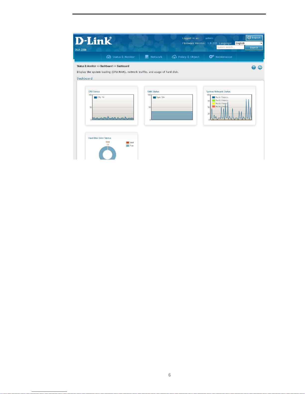
You will see the device’s dashboard when you have successfully connected to the Policy
Manager.
Page 11
D-Link DUA-2000 Policy Manager User Manual
6
Figure 4-1 – Device Dashboard
Changing the Default IP Address
The default IP address of the Policy Manager will need to be changed to match your network
topology. It is recommended that this is completed before the device is connected to the
production network.
1. Navigate to: Network > Device > IP Interface
2. Click Edit next to the System interface
3. Change the address type from DHCP to Static
4. Enter an IP Address, Mask, Gateway and DNS server
5. Press Apply.
Ensure that you can connect to the Polic y Manager using the new IP address.
Page 12

D-Link DUA-2000 Policy Manager User Manual
7
4. System Overview
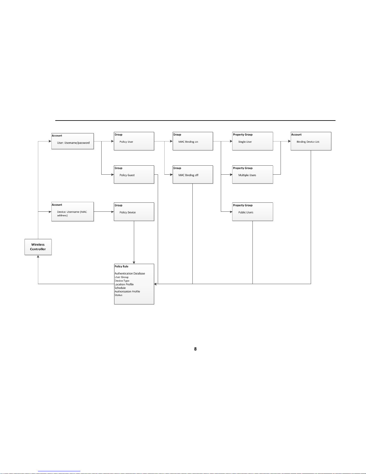
The Policy Manager works by authenticating clients and devices using either a username
and password combination or a MAC address. Depending on the policy type, users will
either be authenticated using their username and password (if they are a configured user on
the system), be authenticated as a guest or be authenticated as a device.
The process begins with an unauthenticated client or device supplying a username and
password or a MAC address to the Wireless Controller. This is, in turn, supplied to the Policy
Manager, which will attempt to authenticate the client using various sources and policies. If it
is not possible to authenticate the client, then the client will be denied access to the network.
The Policy Rule on the Policy Manager is the configuration entity which binds all of the
configuration elements, such as the User Group, Device Type, Location Profile and
Schedule Profile, together. It is linked with the Authentication Database, which can
authenticate against LDAP, Active Directory, POP3, RADIUS and the Policy Manager’s
internal SQL database. Once authentication is complete, then the Authorization Profile is
returned to the Wireless Controller, providing Layer 2 and Layer 3 network settings and
session timeout information to be applied to the client or device.
If a device MAC address is supplied to the Policy Manager as the username, the Policy
Device User Type is applied to the account and the device is authe nticated using the Policy
Rule.
If a username and password is supplied to the Policy Manager, then either the Policy User
or Policy Guest User Types are applied to the account, depending on whether the user has
been configured as a guest. If it has, then the user is authenticated using the Policy Rule.
If a username has been supplied as a Policy User, then there are several more steps
required to authenticate the user and the device they are logging-in from.
The Group MAC Binding feature specifies whether any devices have been associated with
the user account. If they have, then the Property Group Usage field is used, if they have not,
then the user is authenticated using the Policy Rule.
If the device Usage is set to Single User or Multiple users then the Binding Device List on
the Account is consulted to verify that the user is loggin g-in from an approved device. If the
device Usage is set to Public Users, then the user is authenticated using the Policy Rule.
Once it has been verified that the configured user has supplied the correct username and
password and that they’re logging-in from a permitted device, they are authenticated using
the Policy Rule.
Users or devices can be authenticated using either a web page, which allows them to supply
a username and password, or via software running on the directly attached switch, which
authenticates the device using the MAC address as the username.
Look at the diagram in Figure 5-1 for a logical system overview.
Page 13
D-Link DUA-2000 Policy Manager User Manual
8
Figure 5-1 – Logical System Overview
Page 14

D-Link DUA-2000 Policy Manager User Manual
9
5. Network Configuration Example
The D-Link DUA-2000 Poli cy Manager is a highly integrated solution which requires access
to multiple services, such as Wireless Controllers, Unified Access Points (APs) and Layer 2
and 3 switches. This high level of integration requires careful planning and knowledge of
multiple products and technologies to implement. An example of how to configure the
network topology for use with the DUA-2000 is shown below.
NOTE: This configuration applies to the network only and information for
configuring the Policy Manager follows later in the document. It is designed to
illustrate what is required to support a Wireless Controller with external
authentication and captive portal.
Network Requirements
In this example, the following elements are required:
Convention Description
DHCP Server This is a Dynamic Host Configuration Protocol (DHCP) server for
dynamically assigning IP addresses to wireless clients. In the
example below, a router is used for this function.
PoE Switch This is a Layer 2 device that supplies Power over Ethernet (PoE) to
the Wireless APs and performs switching and VLAN tagging
functions.
Wireless AP This advertises the two Service Set Identifiers (SSIDs) for the
wireless Employee (corporate) and Personal (BYOD) networks.
Wireless Controller This controls access to wireless networks and manages wireless
clients and APs. Clients can be authenticated against a number of
sources, including the Policy Manager.
Policy Manager This is responsible for serving the captive portal and providing a
RADIUS source to the Wireless Controller. It itself can be pointed
to a number of authentication sources, including RADIUS, AD
(LDAP), POP3 and RADIUS.
Table 6-1 – Network Requirements
The following are optional but useful for testing:
Convention Description
Wireless device
(laptop, tablet or
smartphone)
This is used to join the wireless networks and test captive portal
and network functionality.
Internet access This can be used to test Internet access for authenticated clients.
TFTP Server This is used for testing the policy that has been applied to client
devices.
HTTP Server This is used for testing the policy that has been applied to client
devices.
Table 6-2 – Optional Requirements
Page 15
D-Link DUA-2000 Policy Manager User Manual
10
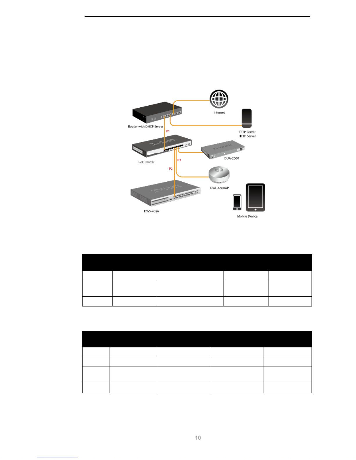
Network Topology
This is an example of how the network can be configured to support wireless client access
control using a captive portal and an external RADIUS server.
The network topology is as follows:
Figure 6-1 – Example Network Topology
The VLANs configured and DHCP address ranges configured on the DHCP server are as
follows:
VLAN
Number
Description Address Range Default
Gateway
Release Time
VLAN 1 Guest VLAN 192.168.10.110 - 150 192.168.10.1 30 Seconds
VLAN 20 Employee
VLAN
192.168.20.110 - 150 192.168.20.1 Default
VLAN 30 Personal VLAN 192.168.30.110 - 150 192.168.30.1 Default
Table 6-3 – VLANs and DHCP Ranges
The addresses assigned to devices are as follows:
VLAN
Number
Device Address Netmask Default
Gateway
VLAN 1 DHCP Server 192.168.10.1 255.255.255.0 192.168.10.1
VLAN 1 PoE Switch 192.168.10.2 255.255.255.0 192.168.10.1
VLAN 1 Wireless
Controller
192.168.10.3 255.255.255.0 192.168.10.1
VLAN 1 Policy Manager 192.168.10.4 255.255.255.0 192.168.10.1
Table 6-4 – Device IP Addresses
The TFTP and HTTP servers in the diagram above are used for testing purposes only.
Page 16

D-Link DUA-2000 Policy Manager User Manual
11
Network Configuration
Use the following steps to configure the Wireless Controller and network devices for use with
the Policy Manager captive portal.
Wireless Controller
These steps can be used to configure the Wireless Controller for use with the captive portal.
The model used in these instructions is the DWS-4026:
1. Give the Wireless Controller an IP address, netmask and default gateway
Navigate to LAN >> Administration >> IP Address.
Set up IP address/ Mask/ Default Gateway.
2. Enable Captive Portal in the Global Configuration
Navigate to LAN >> Security >> Captive Porta l >> Glo bal Conf ig urati on.
Select Enable Captive Portal then press Submit button.
3. Enable Captive Portal in the Captive Portal Configuration.
Navigate to LAN >> Security >> Capti ve Porta l >> CP Conf igura tio n.
Press default entry to edit CP configuration.
Enter Configuration name and Verification mode choose Policy Manager.
Choose RADIUS Auth Server then press submit button.
4. Configure a RADIUS Authentication Server.
Navigate to LAN >> Security >> RADIUS >> RADIU S Auth ent ic ati on Ser ver
Configuration.
Select Add item then enter RADIUS Server Host Address, then chose “Yes” for
Policy Manager.
Enter RADIUS Server Name then select Apply then enter Secret then press submit
button.
5. Discover access points to the use with the P ol ic y Manager .
Navigate to WLAN >> Administration >> Basic Setup >> Discovery.
Enter IP Address Range then press Add button to add IP List into L3/ IP Discovery.
6. Create an Access Point Profile.
Navigate to WLAN >> Administration >> Advanced Configuration >> AP Profiles.
Press default profile then enter profile name.
Select dlink1 SSID and press edit button then enter SSID name and enable Client
QoS.
Policy Manager
Use default settings a nd au thent ic ate against the loc a l user databas e or an exter n al
authentication source.
Page 17

D-Link DUA-2000 Policy Manager User Manual
12
Network Environment
A Dynamic Host Configuration Protocol (DHCP) server and multiple VLANs are required for
Captive Portal. A guest VLAN for unauthenticated guests is requir e d, alo ng with a n
employee VLAN for authenticated corporate clients and a personal VLAN for authenticated
personal clients.
The DHCP server needs to offer an IP address in the range configured for each VLAN and
so the switch port connecting the DHCP server to the local switch needs to be set up for
VLAN tagging. The Wireless APs also need to advertise more than one SSID, one for each
VLAN. The DHCP release time should be set to 30 seconds for the guest VLAN.
Page 18
D-Link DUA-2000 Policy Manager User Manual
13
6. Status & Monitor
Dashboard
Dashboard
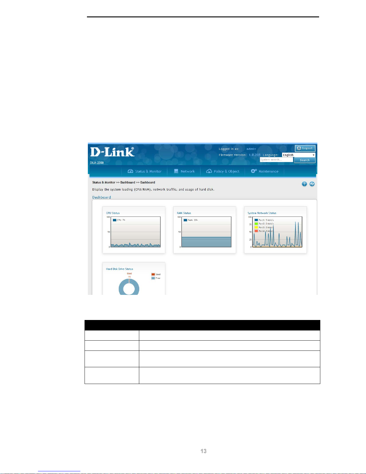
This provides a system overview of the CPU status, RAM status, network status, hard drive
status, association status and number of active users. It is the default page that is displayed
when logging-in to the P olic y Mana ger.
To get to the following page, browse to: Status & Monitor >> Dashboard >> Dashboard:
Figure 7-1 – Dashboard
The following fields are available:
Field Description
CPU Status (%)
The CPU utilization, measured in percent (%).
RAM Status (%)
Memory utilization, measured in percent (%).
System Network
Status (kbit/s)
Combined network utilization of all 4 interfaces, measured in kilobits
per second (kbit/s).
Hard Drive Status
(%)
Disk space utilization, measured in percent (%).
Table 7-1 – Dashboard
Page 19
D-Link DUA-2000 Policy Manager User Manual
14
Network
Interface Utilization
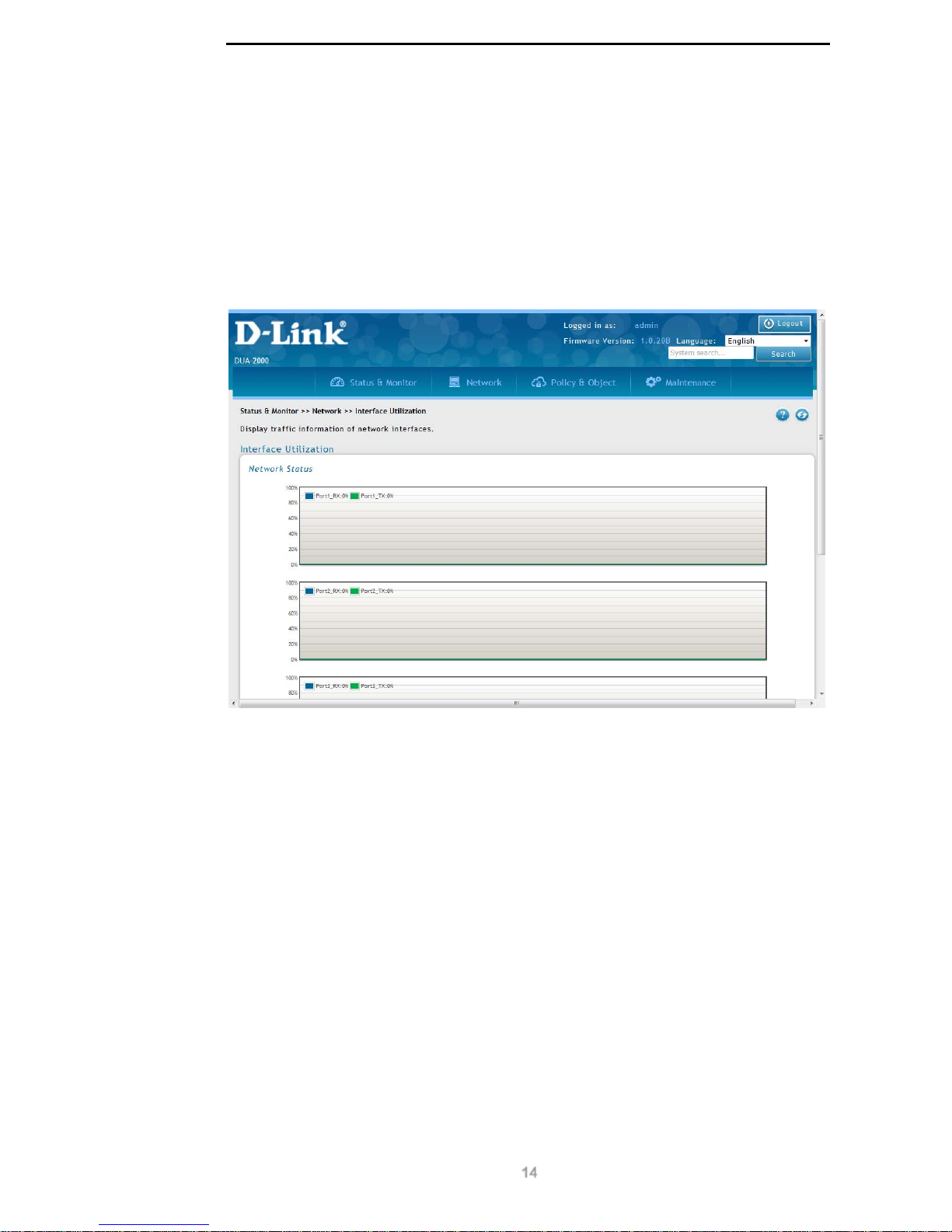
The displays the network interface utilization of the 4 ports on the Policy Manager. The ports
are listed from Port 1 to 4 and refresh automatically.
To get to the following page, browse to: Status & Monitor >> Network >> Interface
Utilization:
Figure 7-2 – Interface Utilization
System
Device Status
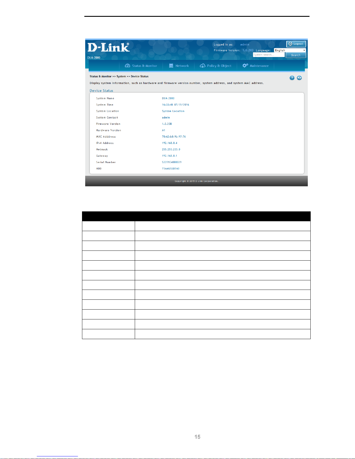
This provides a device overview for the system and includes the system name, time, location,
contact information, software and hardware versions and MAC and IP address information.
To get to the following page, browse to: Status & Monitor >> System >> Device Status:
Page 20
D-Link DUA-2000 Policy Manager User Manual
15
Figure 7-3 – Device Status
The following fields are available:
Field Description
System Name
The hostname of the Policy Manager.
System Time
The system date and time, in the format: HH:MM:SS MM/DD/YYYY.
System Location
The location of the Pol icy Manager.
System Contact
The contact information for the Policy Manager .
Firmware Version
The system firmware version.
Hardware Version
The system hardware version.
MAC Adddress
The system MAC address of the active LAN interface(s).
IPv4 Address
The IP address of the active LAN interface(s).
Netmask
The netmask of the active LAN interface(s).
Gateway
The default gateway address of the active LAN interface(s).
Serial Number
The serial number of the device.
HDD
The serial number of the hard disk driver used by the Policy Manager.
Table 7-2 – Device Status
Logs
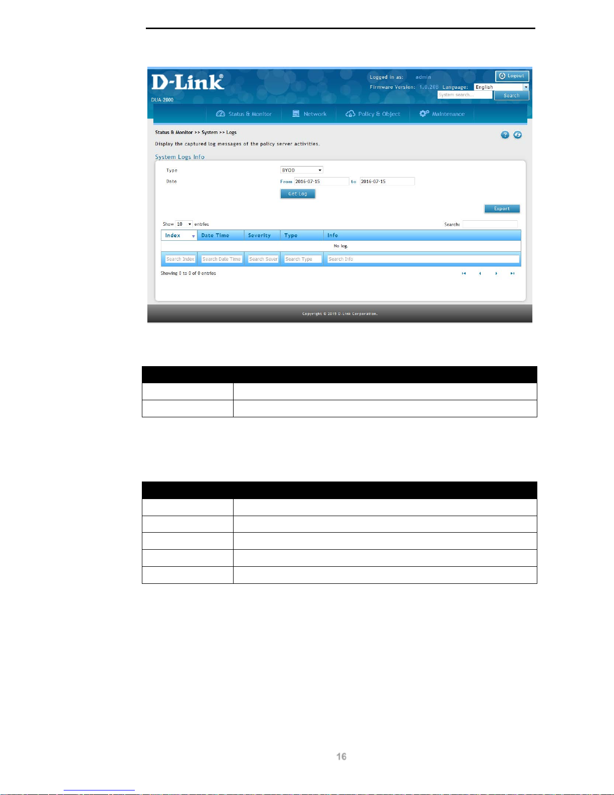
This page is for displaying the logs on the P ol icy Manager.
To get to the following page, browse to: Status & Monitor >> System >> Logs:
Page 21
D-Link DUA-2000 Policy Manager User Manual
16
Figure 7-4 – Logs
The following search fields are available:
Field Description
Type
Choose the log type to search.
Date
The beginning and end date of the log selection.
Table 7-3 – Search Logs
Click Get Log to display logs of the chosen type.
The following fields are available in the results:
Field Description
Index
The log entry index. Higher index values are more recent.
Date Time
The date and time of the log entry.
Severity
The Syslog severity.
Type
The type of log entry.
Info
The log entry contents.
Table 7-4 – Log Results
Click Get Log to display logs of the chosen type.
Click Export to export the logs as a CSV file.
Page 22
D-Link DUA-2000 Policy Manager User Manual
17
7. Network
Device
IP Interface
IP Interface
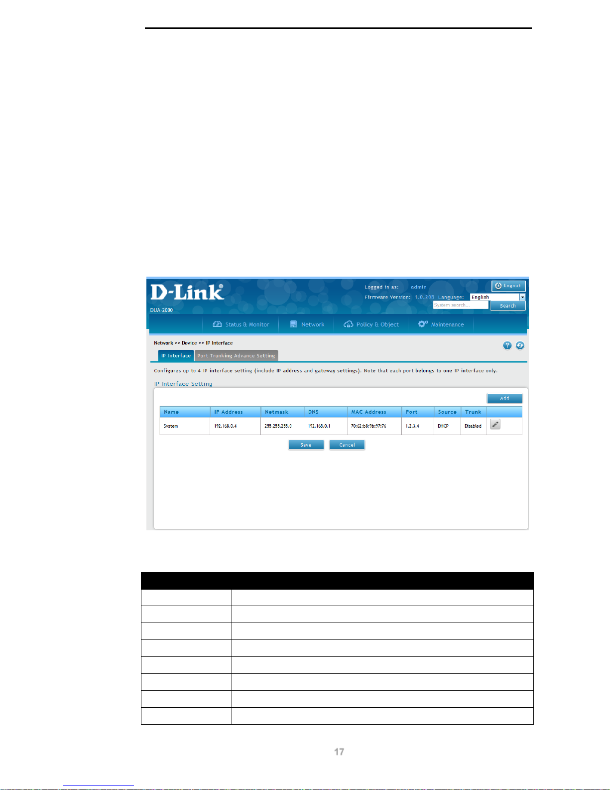
This page is used to set the IP address settings of the DUA-2000. There is one default entry
of ‘System’, which is used to manage the device. Edit this or create a new interface to
connect the DUA-2000 to multiple networks.
To get to the following page, browse to: N etwork >> Device >> IP Interface:
Figure 8-1 – IP Interface Setting
The following fields are available:
Field Description
Name
The name of the network interface or Port Trunk.
IP Address
The IP address of the interface.
Netmask
The netmask of the interface.
DNS
The Domain Name System (DNS) servers for the interface.
MAC Address
The Media Access Control (MAC) address of the interface.
Port
The ports that the interface configuration applies to.
Source
The IP address assignment type for the interface (static or DHCP).
Trunk
The Port Trunk status for the interface (Enabled or Disabled)
Table 8-1 – IP Interface Setting
Page 23
D-Link DUA-2000 Policy Manager User Manual
18
Click Add to add an IP interface.
Click Edit to edit existing interface settings.
Click Delete to delete an interface.
Click Save to save the changes made.
Click Cancel to revert the settings to their previous state.
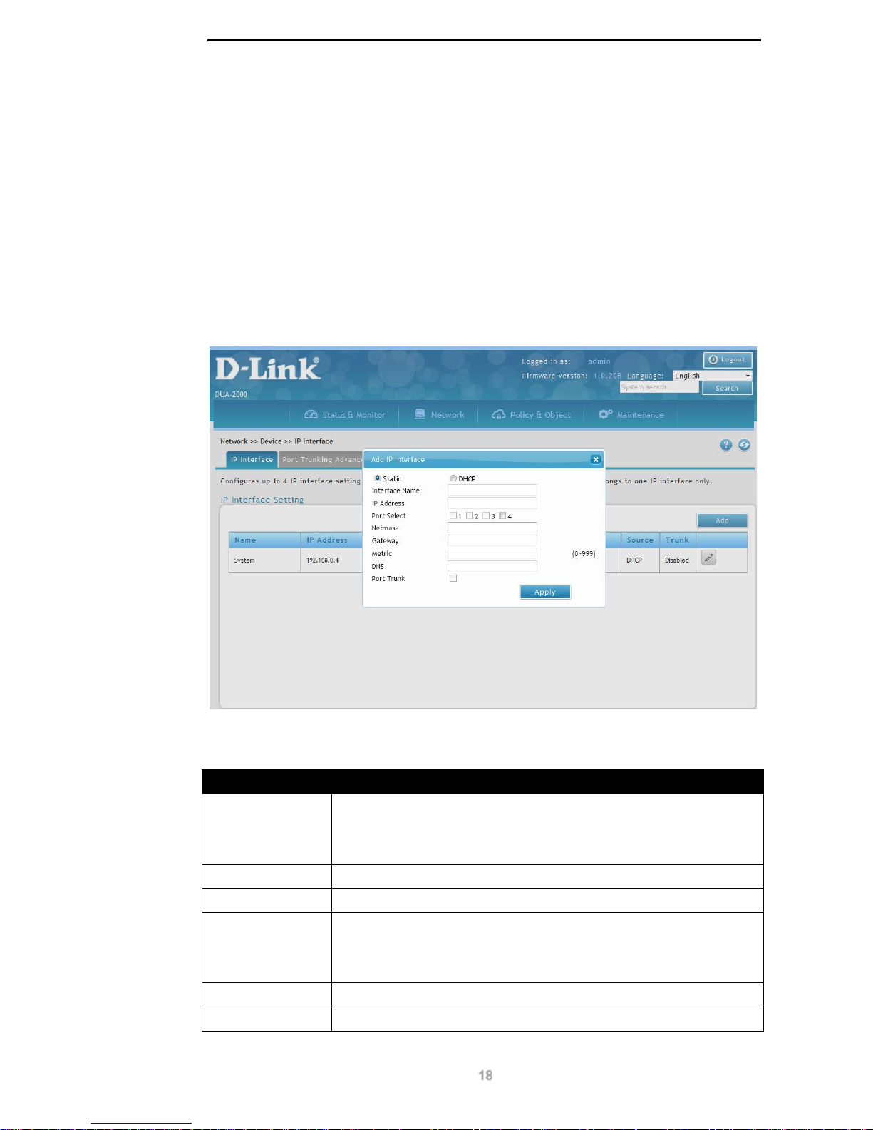
Add IP Interface
Click the Add or Edit buttons to view the following window:
Figure 8-2 – Add IP Interface
The following fields can be configured:
Field Description
Static or DHCP
Set the address assignment type; static IP address or dynamicallyassigned IP address (DHCP). If Static is chosen, it is possible to enter
values into the fields below. Is DHCP is chosen, it is only possible to
select ports to apply the settings to and create a Port Trunk.
Interface Name
Name the interface.
IP Address
Enter the IPv4 address for the interface.
Port Select
Select the physical switch port on the DUA-2000 to assign the IP
address to. At least one switch port must be selected when applying
the IP address. The same interface cannot be given more than one IP
address. Select multiple ports to create a Port Trunk (see below).
Netmask
Assign a subnet mask to the interface.
Gateway
Assign a default gateway for the interface.
Page 24
D-Link DUA-2000 Policy Manager User Manual
19
Metric
The metric for the interface in the routing table on the DUA-2000. This
decides the preference of the interface for outgoing traffic.
Default is 0. The range is: 0 - 999.
DNS
Assign DNS servers for the interface.
Port Trunk
Configure the ports as a trunk. This binds more than one physical
interface together to create an interface bundle.
Select a bundle negotiation type of: Static or LACP.
Static creates a port trunk with the network switch without any
negotiation. Selecting Link Aggregation Control Protocol (LACP)
allows the DUA-2000 to negotiate a port trunk with the network switch.
Table 8-2 – Add IP Interface
Click Apply to apply the settings.
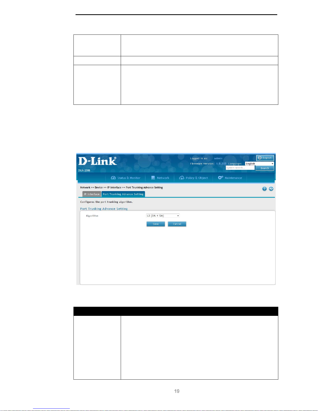
Port Trunking Advance Setting
Click the Port Trunking Advance Setting tab to view the following window:
Figure 8-3 – Port Trunk Advance Setting
The following fields can be configured:
Field Description
Algorithm
Choose the load-balancing algorithm for the Port Trunk. The options
are:
L2 (DA + SA)
Layer 2, destination MAC address and source MAC address
L2+L3 (MAC + IP)
Layer 2 and 3, MAC address and IP address
L3+L4 (IP + TCP/UDP)
Page 25
D-Link DUA-2000 Policy Manager User Manual
20
Layer 3 and 4, IP address and TCP/UDP port number.
Table 8-3 – Port Trunk Advance Setting
Click Save to save the changes made.
Click Cancel to revert the settings to their previous state.
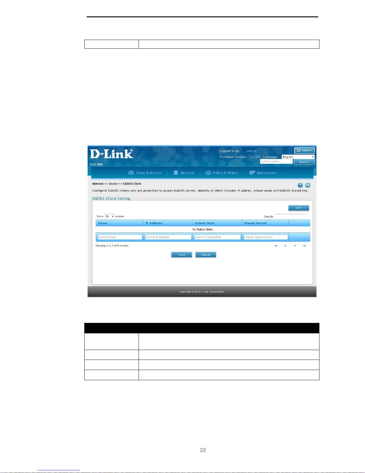
RADIUS Client
This page is used to enter the RADIUS client information for RADIUS clients accessing the
RADIUS server on the DUA-2000.
To get to the following page, browse to: Netw o rk >> Device >> RADIUS Client:
Figure 8-4 – RADIUS Server Setting
The following fields are available:
Field Description
Name
The name of the RADIUS client that will connect to the RADIUS
server.
IP Address
The IP address of the client.
Subnet Mask
The subnet mask of the client.
Shared Secret
The shared secret for the RADIUS client and server.
Table 8-4 – RADIUS Server Setting
Click Add to add a RADIUS server.
Click Edit to edit existing RADIUS servers.
Click Delete to delete a RADIUS server.
Click Save to save the changes made.
Page 26
D-Link DUA-2000 Policy Manager User Manual
21
Click Cancel to revert the settings to their previous state.
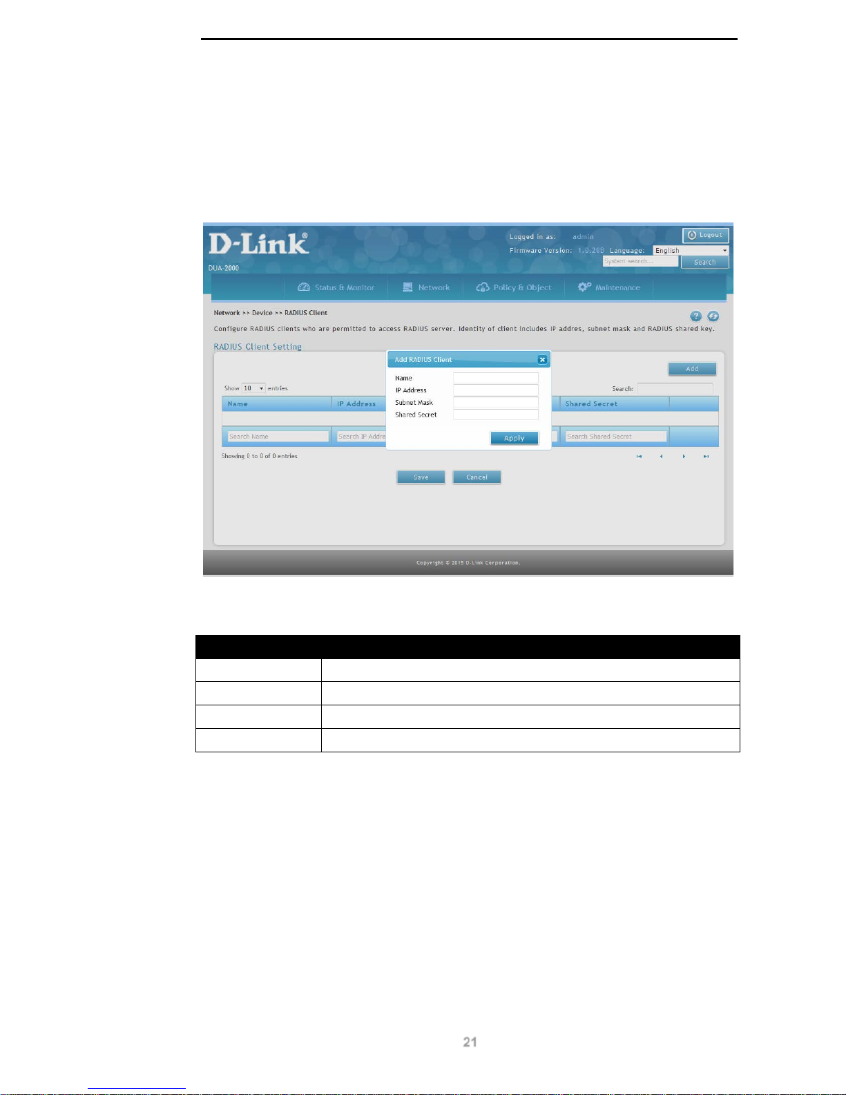
Add RADIUS Server Client
Click the Add or Edit buttons to view the following window:
Figure 8-5 – Add RADIUS Server Client
The following fields can be configured:
Field Description
Name
Name the RADIUS client that will connect to the RADIUS server.
IP Address
Enter the IP address of the client.
Subnet Mask
Enter the subnet mask of the client.
Shared Secret
Enter a shared secret for the RADIUS client and server.
Table 8-5 – Add RADIUS Server Client
Click Apply to apply the settings.
Page 27
D-Link DUA-2000 Policy Manager User Manual
22
Identity Domain
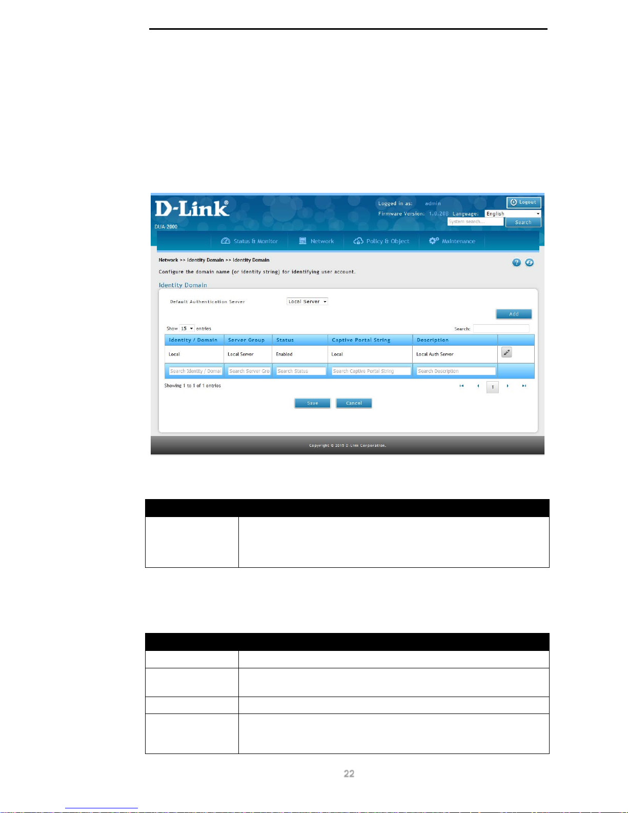
Identity Domain
This is used to set the authentication sources for wireless clients. It is based on the external
servers configured on the External Server page.
To get to the following page, browse to: Network >> Identity Domain >> Identity Domain:
Figure 8-6 – Identity Domain
The following fields are available:
Field Description
Default
Authentication
Server
The Default Authentication Ser ver used if the user account cannot be
authenticated against the Identity Domain. This can be Disabled,
Local Server, or one of the Identity Domains entered. The default is
Disabled.
Table 8-6 – Identity Domain 1
Click Add to add an Identity Domain.
The following fields are available:
Field Description
Identity / Domain
The name of the Identity Domain.
Server Group
The Server Group used for authentication, defined on the External
Server page. The local DUA-2000 database (SQL) is the default.
Status
The Captive Portal status.
Captive Portal
String
The Captive Portal String. This is appended to the client’s username
by the Wireless Controller and is used to identify the External Server if
more than one authentication source exists.
Page 28
D-Link DUA-2000 Policy Manager User Manual
23
Description
The description of the Identity Domain.
Table 8-7 – Identity Domain 2
Click Edit to edit existing Identity Domain.
Click Delete to delete an Identity Domain. Please note that the Local Identity Domain cannot
be deleted.
Click Save to save the changes made.
Click Cancel to revert the settings to their previous state.
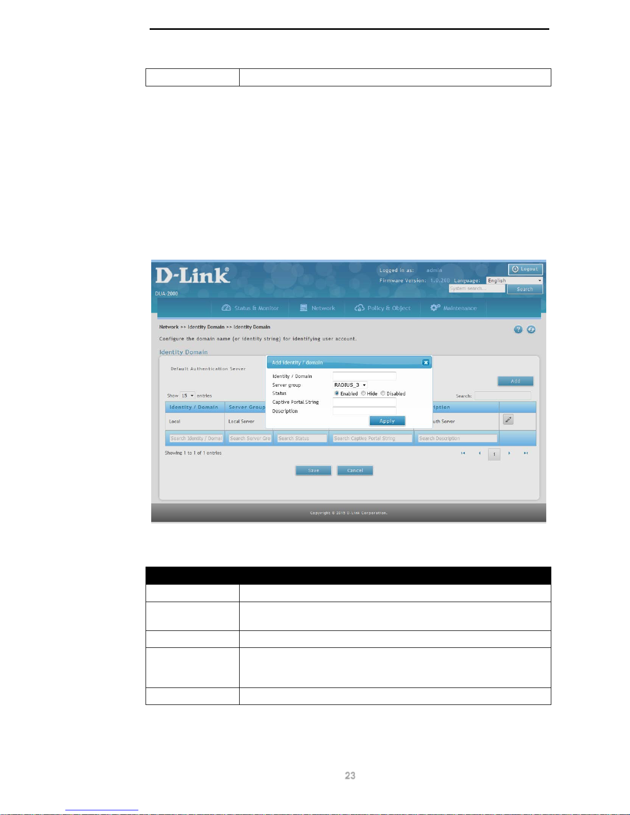
Add Identity / Domain
Click the Add or Edit buttons to view the following window:
Figure 8-7 – Add Identity / Domain
The following fields can be configured:
Field Description
Identity / Domain
The name of the Identity Domain.
Server Group
The Server Group to authenticate against. This is configured on the
External Server page.
Status The status of the Identity Domain. This can be Enabled or Disabled.
Captive Portal
String
The Captive Portal String. This is appended to the client’s username
by the Wireless Controller and is used to identify the External Server if
more than one authentication source exists.
Description
The description of the Identity Domain.
Table 8-8 – Add Identity / Domain
Click Apply to apply the settings.
Page 29
D-Link DUA-2000 Policy Manager User Manual
24
External Server
LDAP
Lightweight Directory Authentication Protocol (LDAP) is used for authenticating users and
devices over an IP network.
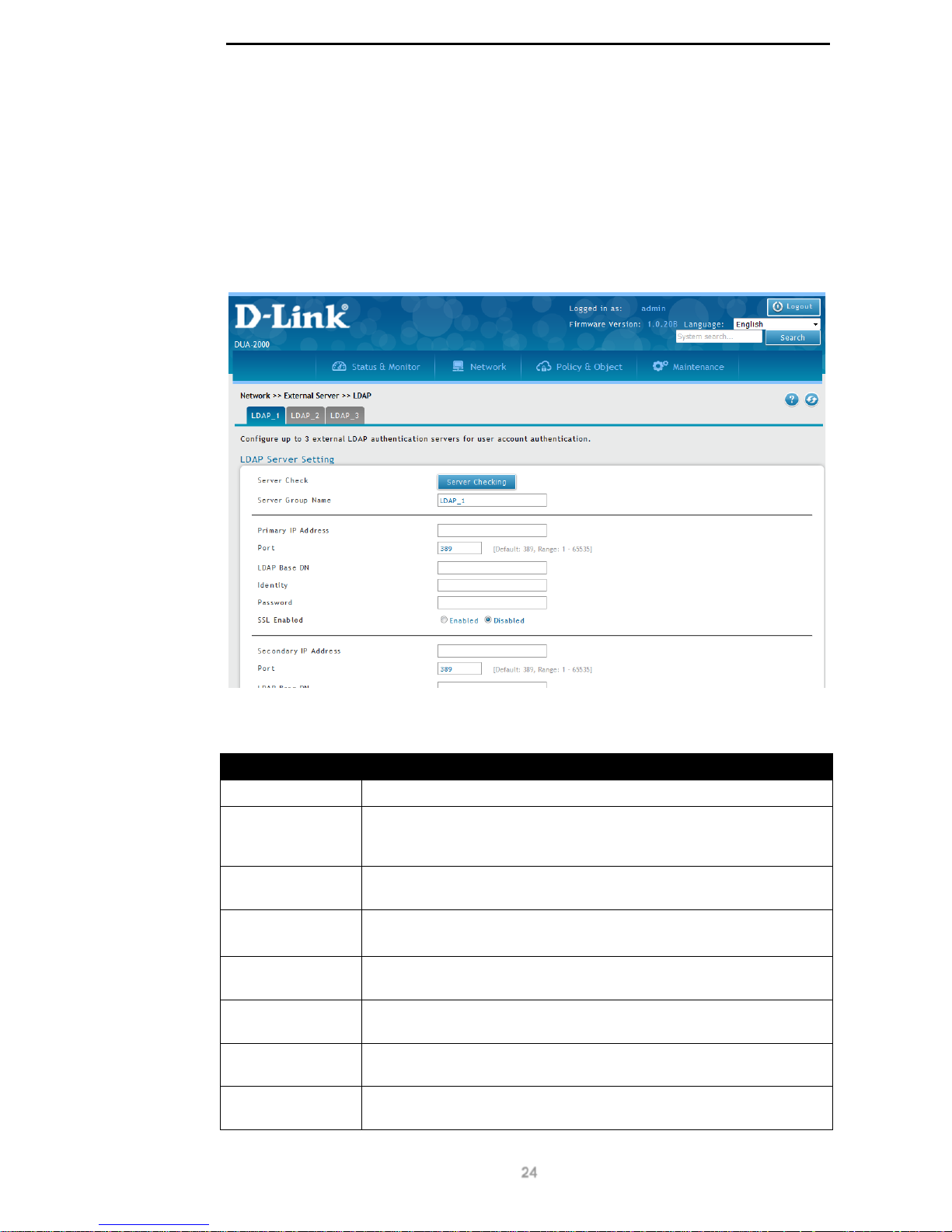
To get to the following page, browse to: Network >> External Server >> LDAP:
Figure 8-8 – LDAP Server Setting
The following fields are available:
Field Description
Server Check
Click this button to test the LDAP server configuration.
Server Group
Name
Create a Server Group Name. This is referenced by the Identity /
Domain and is used to group the LDAP servers defined on this page.
Up to 3 Server Groups can be defined.
Primary IP
Address
The IP address of the primary LDAP server.
Port
The port to connect to on the LDAP server.
Default is 389. The range is: 1 – 65535.
LDAP Base DN
The LDAP search base for the container that contains the users or
devices to be authenticated on the LDAP server.
Identity
The username of the administrative user that is used to log-in to the
LDAP server and authenticate the client.
Password
The password of the administrative user that is used to log-in to the
LDAP server and authenticate the client.
SSL Enabled
Click to enable or disable SSL for LDAP authentication. The options
are Enabled or Disabled.
Page 30

D-Link DUA-2000 Policy Manager User Manual
25
Secondary IP
Address
The IP address of the secondary LDAP server.
Port
The port to connect to on the LDAP server.
Default is 389. The range is: 1 – 65535.
LDAP Base DN
The LDAP search base for the container that contains the users or
devices to be authenticated on the LDAP server.
Identity
The username of the administrative user that is used to log-in to the
LDAP server and authenticate the client.
Password
The password of the administrative user that is used to log-in to the
LDAP server and authenticate the client.
SSL Enabled
Click to enable or disable SSL for LDAP authentication. The options
are Enabled or Disabled.
Third IP Address
The IP address of the third LDAP server.
Port
The port to connect to on the LDAP server.
Default is 389. The range is: 1 – 65535.
LDAP Base DN
The LDAP search base for the container that contains the users or
devices to be authenticated on the LDAP server.
Identity
The username of the administrative user that is used to log-in to the
LDAP server and authenticate the client.
Password
The password of the administrative user that is used to log-in to the
LDAP server and authenticate the client.
SSL Enabled
Click to enable or disable SSL for LDAP authentication. The options
are Enabled or Disabled.
Table 8-9 – LDAP Server Setting
Click Save to save the changes made.
Click Cancel to revert the settings to their previous state.
AD
Active Directory (AD) is a Microsoft implementation of LDAP which is used to authenticate
clients and devices over an IP network.
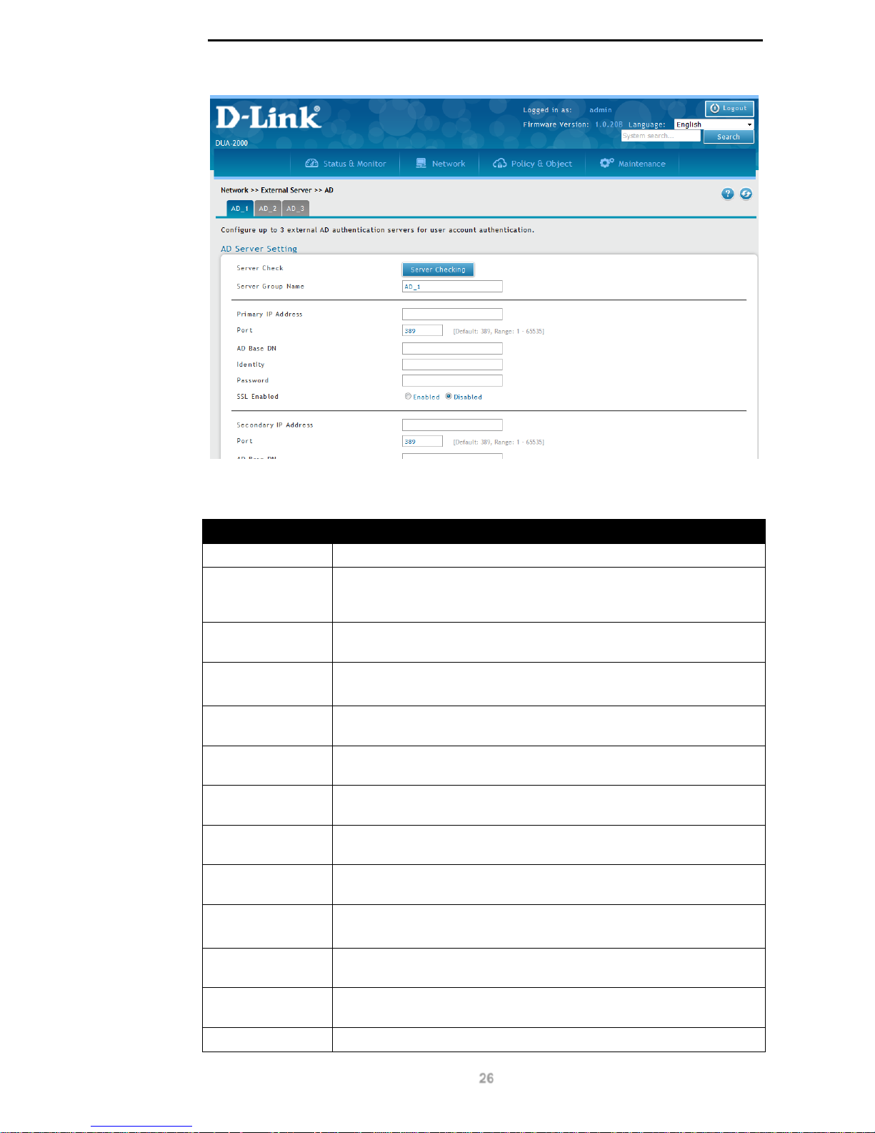
To get to the following page, browse to: Network >> External Server >> AD:
Page 31
D-Link DUA-2000 Policy Manager User Manual
26
Figure 8-9 – AD Server Setting
The following fields are available:
Field Description
Server Check
Click this button to test the AD server configuration.
Server Group
Name
Create a Server Group Name. This is referenced by the Identity /
Domain and is used to group the AD servers defined on this page. Up
to 3 Server Groups can be defined.
Primary IP
Address
The IP address of the primary AD server.
Port
The port to connect to on the AD server.
Default is 389. The range is: 1 – 65535.
AD Base DN
The AD search base for the container that contains the users or
devices to be authenticated on the AD server.
Identity
The username of the administrative user that is used to log-in to the
AD server and authenticate the client.
Password
The password of the administrative user that is used to log-in to the
AD server and authenticate the client.
SSL Enabled
Click to enable or disable SSL for AD authentication. The options are
Enabled or Disabled.
Secondary IP
Address
The IP address of the secondary AD server.
Port
The port to connect to on the AD server.
Default is 389. The range is: 1 – 65535.
AD Base DN
The AD search base for the container that contains the users or
devices to be authenticated on the AD server.
Identity
The username of the administrative user that is used to log-in to the
AD server and authenticate the client.
Password
The password of the administrative user that is used to log-in to the
Page 32
D-Link DUA-2000 Policy Manager User Manual
27
AD server and authenticate the client.
SSL Enabled
Click to enable or disable SSL for AD authentication. The options are
Enabled or Disabled.
Third IP Address
The IP address of the third AD server.
Port
The port to connect to on the AD server.
Default is 389. The range is: 1 – 65535.
AD Base DN
The AD search base for the container that contains the users or
devices to be authenticated on the AD server.
Identity
The username of the administrative user that is used to log-in to the
AD server and authenticate the client.
Password
The password of the administrative user that is used to log-in to the
AD server and authenticate the client.
SSL Enabled
Click to enable or disable SSL for AD authentication. The options are
Enabled or Disabled.
Table 8-10 – AD Server Setting
Click Save to save the changes made.
Click Cancel to revert the settings to their previous state.
POP3
Post Office Protocol version 3 (POP3) is a mail retrieval protocol which can also be used for
authentication of clients and devices over an IP net wo rk.
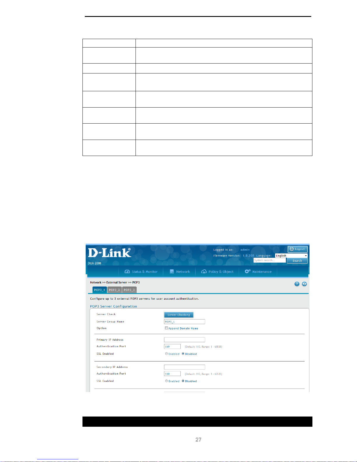
To get to the following page, browse to: N et work >> External Serv e r >> POP3:
Figure 8-10 – POP3 Server Configuration
The following fields are available:
Field Description
Page 33

D-Link DUA-2000 Policy Manager User Manual
28
Server Check
Click this button to test the POP3 server configuration.
Server Group
Name
Create a Server Group Name. This is referenced by the Identity /
Domain and is used to group the POP3 servers defined on this page.
Up to 3 Server Groups can be defined.
Option
Tick the Append Domain Name box to append the domain name to
POP3 server authentication requests.
Primary IP
Address
The IP address of the primary POP3 server.
Authentication
Port
The TCP port to use for POP3 authentication. Range: 1 – 65535. The
default is: 110.
SSL Enable
Click to enable or disable SSL for POP3 authentication. The options
are Enabled or Disabled.
Secondary IP
Address
The IP address of the secondary POP3 server.
Authentication
Port
The TCP port to use for POP3 authentication. Range: 1 – 65535. The
default is: 110.
SSL Enable
Click to enable or disable SSL for POP3 authentication. The options
are Enabled or Disabled.
Third IP Address
The IP address of the third POP3 server.
Authentication
Port
The TCP port to use for POP3 authentication. Range: 1 – 65535. The
default is: 110.
SSL Enable
Click to enable or disable SSL for POP3 authentication. The options
are Enabled or Disabled.
Table 8-11 – POP3 Server Configuration
Click Save to save the changes made.
Click Cancel to revert the settings to their previous state.
RADIUS
The Remote Authentication Dial-In User Service (RADIUS) client is used by the Policy
Manager to authenticate users and devices against an external RADIUS source. The
RADIUS protocol supports Authentication, Authorization and Accounting (AAA).
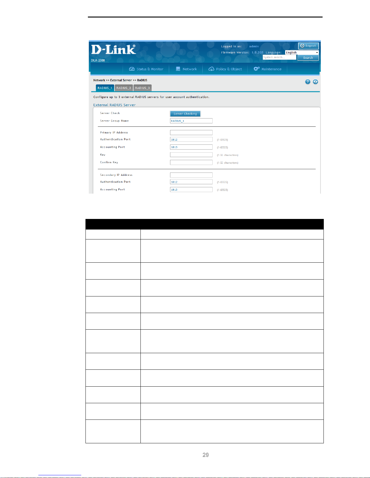
To get to the following page, browse to: Network >> External Server >> RADIUS:
Page 34
D-Link DUA-2000 Policy Manager User Manual
29
Figure 8-11 – RADIUS Server (Client)
The following fields are available:
Field Description
Server Check
Click this button to test the RADIUS server configuration.
Server Group
Name
Create a Server Group Name. This is referenced by the Identity /
Domain and is used to group the RADIUS servers defined on this
page. Up to 3 Server Groups can be defined.
Primary IP
Address
The IP address of the primary RADIUS server.
Authentication
Port
The TCP port to use for RADIUS authentication. Range: 1 - 65535.
The default is: 1812.
Accounting Port
The TCP port to use for RADIUS accounting. Range: 1 - 65535. The
default is: 1813.
Key
The password of the administrative user that is used to log-in to the
RADIUS server and authenticate the client. Range: 1 - 32 characters.
Confirm Key
Confirm the password of the administrative user that is used to log-in
to the RADIUS server and authenticate the client. Range: 1 - 32
characters.
Secondary IP
Address
The IP address of the secondary RADIUS server.
Authentication
Port
The TCP port to use for RADIUS authentication. Range: 1 - 65535.
The default is: 1812.
Accounting Port
The TCP port to use for RADIUS accounting. Range: 1 - 65535. The
default is: 1813.
Key
The password of the administrative user that is used to log-in to the
RADIUS server and authenticate the client. Range: 1 - 32 characters.
Confirm Key
Confirm the password of the administrative user that is used to log-in
to the RADIUS server and authenticate the client. Range: 1 - 32
characters.
Page 35
D-Link DUA-2000 Policy Manager User Manual
30
Third IP Address
The IP address of the third RADIUS server.
Authentication
Port
The TCP port to use for RADIUS authentication. Range: 1 - 65535.
The default is: 1812.
Accounting Port
The TCP port to use for RADIUS accounting. Range: 1 - 65535. The
default is: 1813.
Key
The password of the administrative user that is used to log-in to the
RADIUS server and authenticate the client. Range: 1 - 32 characters.
Confirm Key
Confirm the password of the administrative user that is used to log-in
to the RADIUS server and authenticate the client. Range: 1 - 32
characters.
Table 8-12 – RADIUS Server (Client)
Click Save to save the changes made.
Click Cancel to revert the settings to their previous state.
Page 36
D-Link DUA-2000 Policy Manager User Manual
31
8. Policy & Object
Policy Rule
Rule
The Policy Rule links all of the different configuration elements that are used to authenticate
a user or device. It is based on the User Group, Device Type, Location Profile and Schedule
Profile and references the Auth ent ic ati on Data bas e configured in the Identity Domain. If it is
not possible to authenticate a user or device, then they are denied access by the Wireless
Controller. If it is possible to authenticate a user or device, then the Authorization Profile is
returned to the Wireless Controller.
NOTE: It is not possible to deny access to a user or device using the Policy
Rule. This is done by the Wireless Controller and is based on the Policy Rule
being unable to authenticate the device or user.
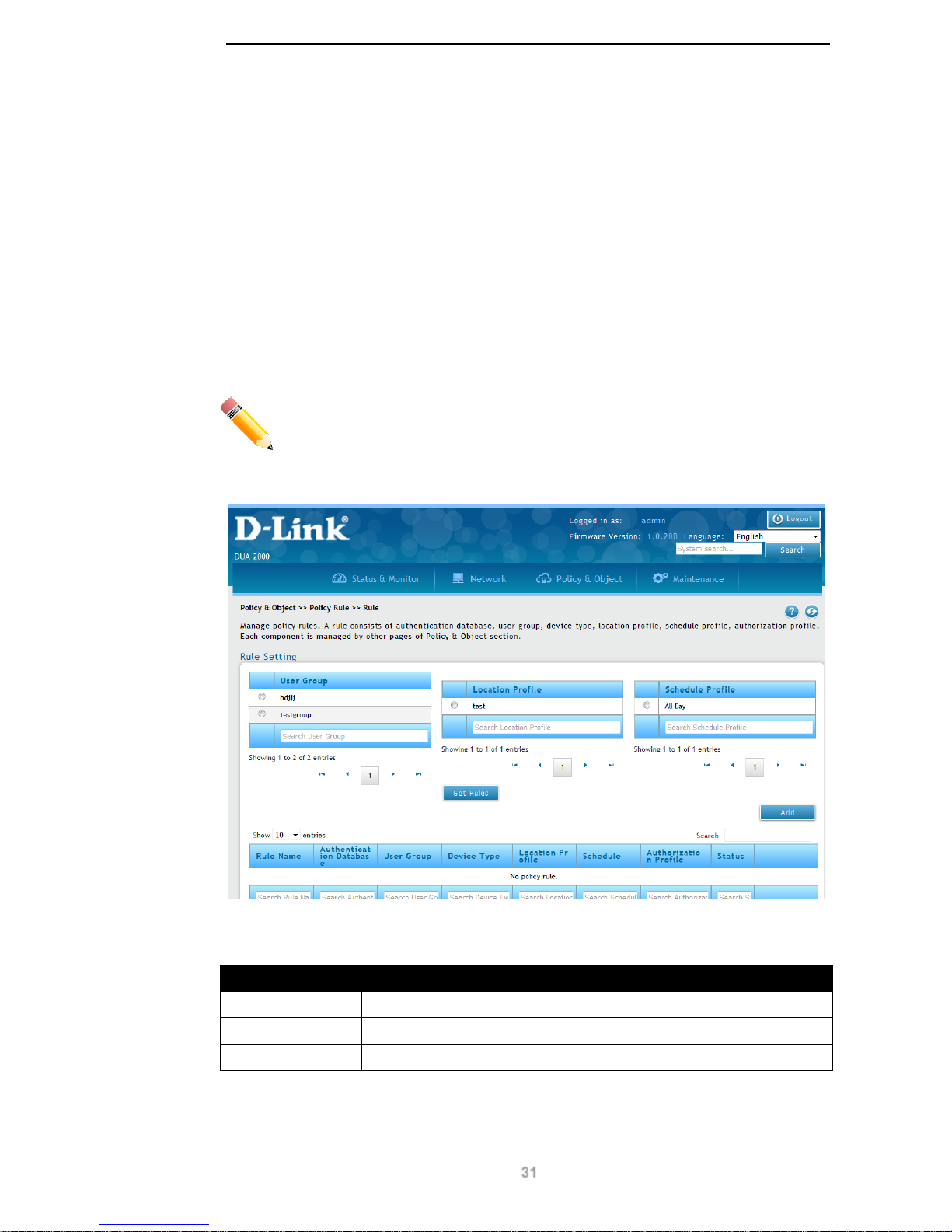
To get to the following page, browse to: Policy & Object >> Policy Rule >> Rule:
Figure 9-1 – Rule
The following fields are available:
Field Description
User Group
Select the User Group to display the policy rules for.
Location Profile
Select the Location Prof ile to display the policy rules for.
Schedule Profile
Select the Schedule Prof ile to display the policy rules for.
Table 9-1 – Rule 1
Click Get Rules to search for rules using the fields selected.
Page 37
D-Link DUA-2000 Policy Manager User Manual
32
The following fields are available:
Field Description
Rule Name
The name of the Po licy Rule.
Authentication
Database
The database to use for authentication. This is defined on the Identity
Domain page. Each database can only be selected once, apart from
the default Local Server (SQL) database.
User Group
The User Group for the Policy Rule. This links the Account, username,
password, User Type, devices and Usage with the Policy Rule.
Device Type
The Device Type the Policy Rule applies to. This is applied in the
Device section.
Location Profile
The Location Profile the Po licy Rule applies to.
Schedule
The Schedule Profile that applies to the Policy Rule.
Authorization
Profile
The Authorization Profil e that applies to the Policy Rule.
Status The status of the Policy Rule. This can be Enabled or Disabled.
Table 9-2 – Rule 2
Click Add to add a Policy Rule.
Click Edit to edit existing Policy Rule settings.
Click Delete to delete a Policy Rule.
Add Policy Rule
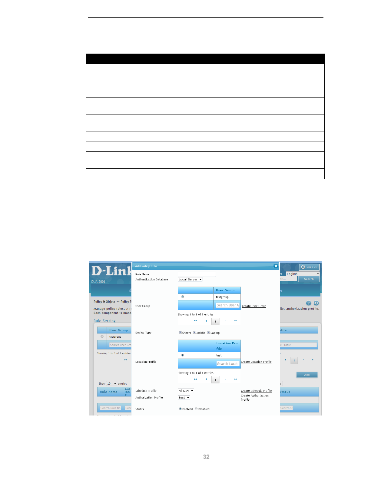
Click the Add or Edit buttons to view the following window:
Figure 9-2 – Add Policy Rule
The following fields can be conf igur ed:
Page 38

D-Link DUA-2000 Policy Manager User Manual
33
Field Description
Rule Name
The name of the Po licy Rule.
Authentication
Database
The database to use for authentication. This is defined on the Identity
Domain page. Each database can only be selected once, apart from
the default Local Server (SQL) database.
User Group
The User Group for the Policy Rule. This links the Account, username,
password, User Type, devices and Usage with the Policy Rule. Click
Create User Group to create a new User Group.
Device Type
The Device Type the Policy Rule applies to. This is applied on the
Device page and is another parameter through which to authenticate
devices. It can be set to:
Others. Used to classify any device which is not a mobile phone or
laptop on the Device page.
Mobile. Used to classify a device as a mobile phone on the Device
page.
Laptop. Used to classify a device as a mobile phone on the Device
page.
Location Profile The Location Profile the Policy Rule applies to. Click Create Location
Profile to create a new Location Profile.
Schedule Profile The Schedule that applies to the Policy Rule. Click Create Schedule
Profile to create a new Schedule Profile.
Authorization
Profile
The Authorization Profil e that applies to the Policy Rule. Click Create
Authorization Profile to create a new Authorization Profile.
Status The status of the Policy Rule. This can be Enabled or Disabled.
Table 9-3 – Add Policy Rule
Click Apply to apply the settings.
Page 39
D-Link DUA-2000 Policy Manager User Manual
34
Client
User Database
Group
The User Database is a way of managing users and the devices associated with them. If the
MAC Binding feature is enabled, then both the user and device are authenticated. If the
MAC Binding feature is disabled, then only the user is authenticated. This works in
conjunction with the Binding Device Lis t, w hich is used to ass oc iate de vices w ith user
accounts. The Group is referenced by the Policy Rule.
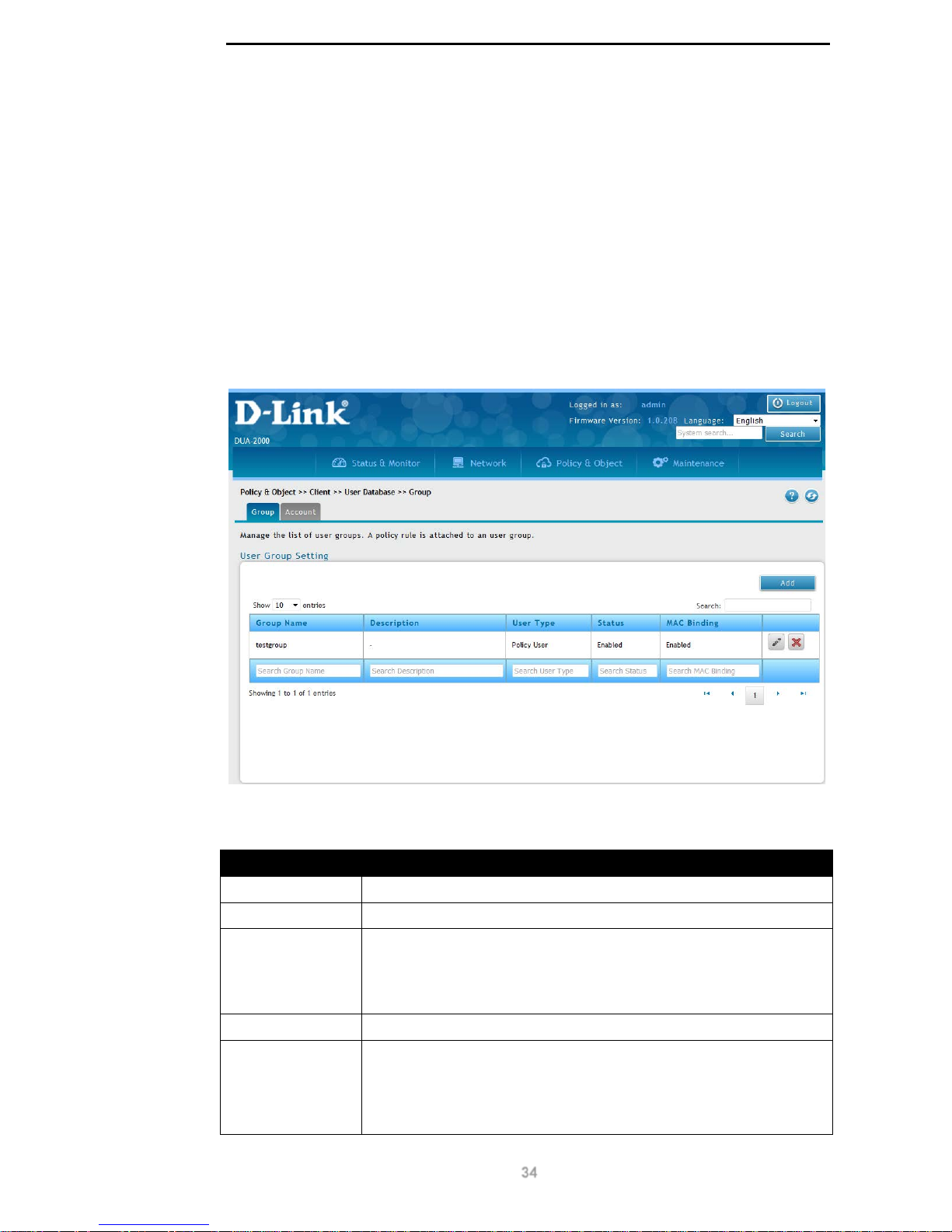
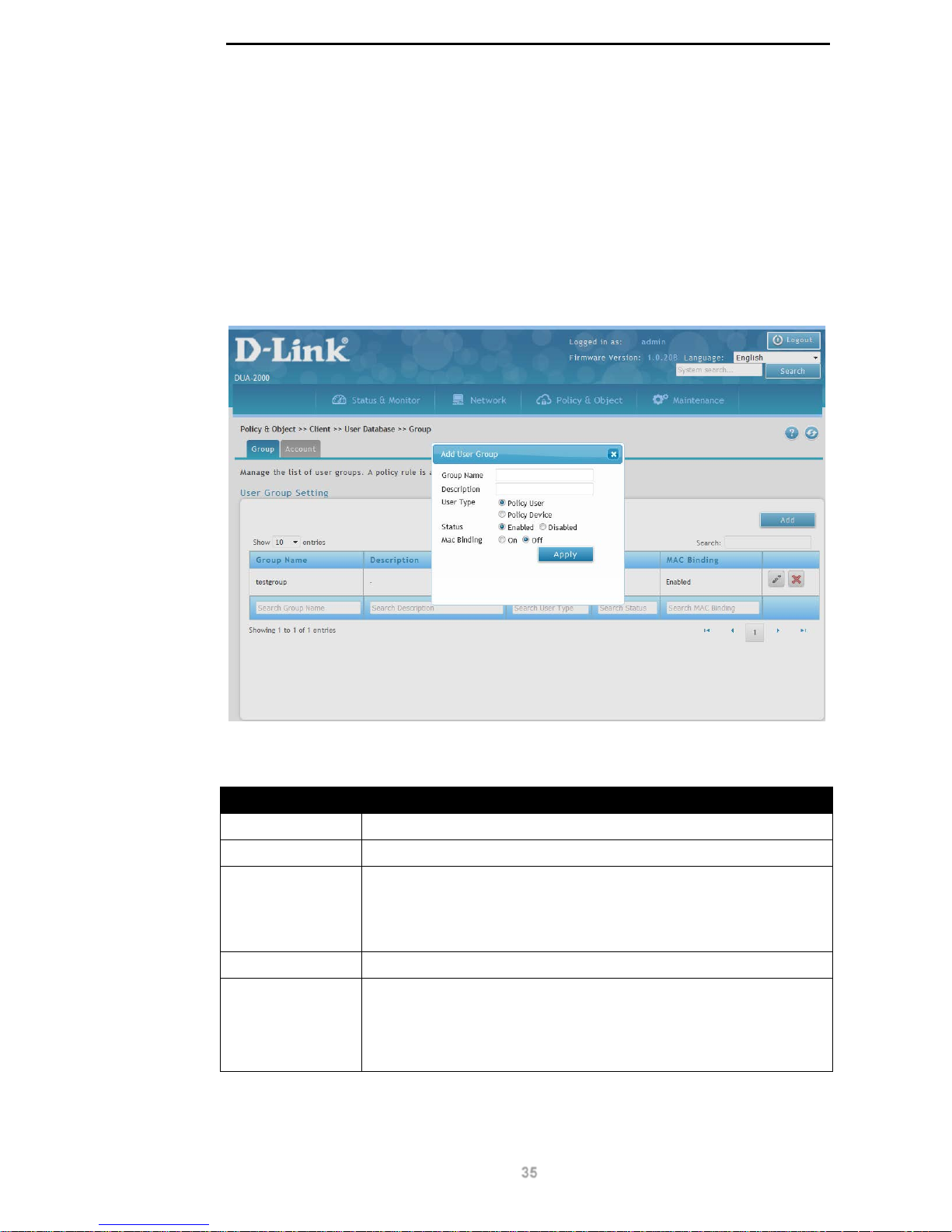
To get to the following page, browse to: Policy & Object >> Client >> User Database:
Figure 9-3 – Group
The following fields are available:
Field Description
Group Name
The name of the user group.
Description
The description of the user group.
User Type
The type of user. This can be:
Policy User. This is a user-based account on the Policy Manager.
Policy Device. This is a device-based account on the Policy
Manager.
Status The user status. This can be Enabled or Disabled.
MAC Binding
This is whether any devices are associated with the user accounts. If
it is set to On, then it’s possible to assign devices to the account and
both the user and device are authenticated. If it is set to Off, then it is
not possible to assign devices to the account and only the user is
authenticated. This can be On or Off.
Page 40
D-Link DUA-2000 Policy Manager User Manual
35
Table 9-4 – Group
Click Add to add a User Group.
Click Edit to edit existing User Group settings.
Click Delete to delete a User Group.
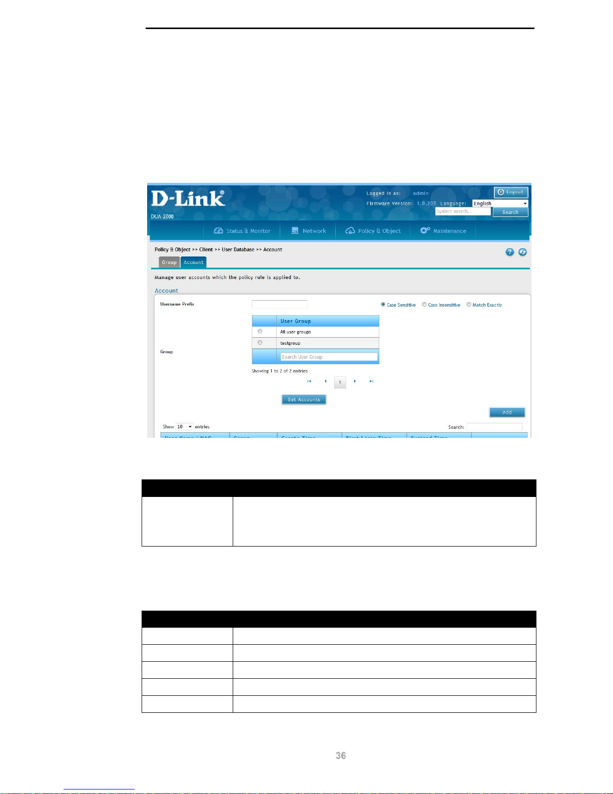
Add User Group
Click the Add or Edit buttons to view the following window:
Figure 9-4 – Add User Group
The following fields can be configured:
Field Description
Group Name
The name of the user group.
Description
The description of the user group.
User Type
The type of user. This can be:
Policy User. This is a user-based account on the Policy Manager.
Policy Device. This is a device-based account on the Policy
Manager.
Status The user status. This can be Enabled or Disabled.
Mac Binding
This is whether any devices are associated with the user accounts. If
it is set to On, then it’s possible to assign devices to the account and
both the user and device are authenticated. If it is set to Off, then it is
not possible to assign devices to the account and only the user is
authenticated. This can be On or Off.
Table 9-5 – Add User Group
Click Apply to apply the settings.
Page 41
D-Link DUA-2000 Policy Manager User Manual
36
Account
The Account links the Username, Password, Binding Device List and Group. The Binding
Device List is the devices that a user is permitted to log in from. The Group is associated
with the Policy Rule and provides the list of users and devices that can be authenticated by
the Policy Rule.
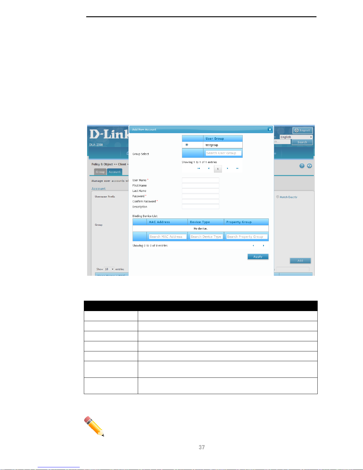
To get to the following page, browse to: Policy & Object >> Client >> User Database and
click on the Account tab:
Figure 9-5 – Account
The following fields are available:
Field Description
Username Prefix Enter a Username Pref ix and select Case Sensit iv e, Case
Insensitive or Match Exactly for the search type. Select the group
from the Group menu or choose All groups to search for all accounts
on the Policy Manager.
Table 9-6 – Account 1
Click Get Accounts to retrieve user account information for the specified group.
The following fields are available:
Field Description
User Name / MAC
The name or MAC address of the user or device.
Group
The group the user or device belongs to.
Create Time
The creation time of the user or device on the Policy Manager.
First Login Time
The time that the user first logged-in.
Expired Time
The time that the user account expired on the Policy Manager.
Table 9-7 – Account 2
Page 42
D-Link DUA-2000 Policy Manager User Manual
37
Click Add to add a User Group.
Click Edit to edit existing User Group settings.
Click Detail to get an overv ie w of the user acco unt.
Click Delete to delete a User Group.
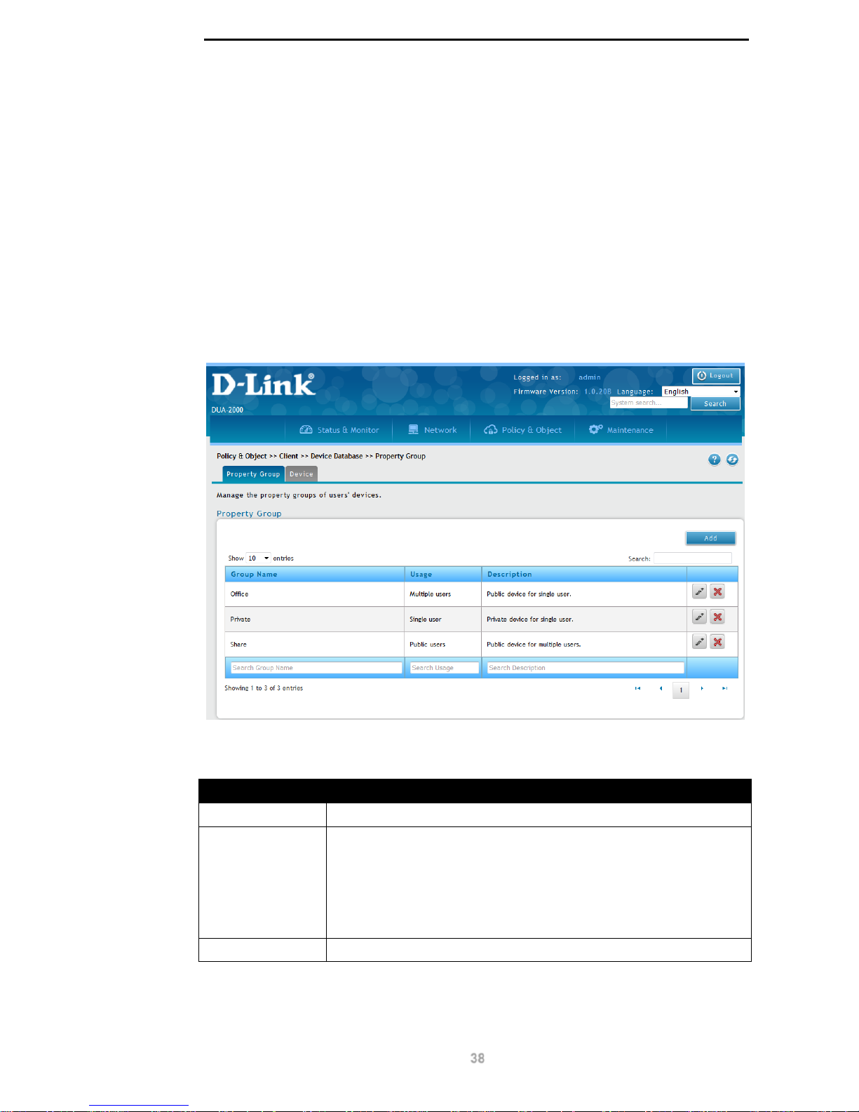
Add New Account
Click the Add or Edit buttons to view the following window:
Figure 9-6 – Add New Account
The following fields can be configured:
Field Description
Group Select
Select the group that the user belongs to.
User Name
Enter the user name of the user.
First Name
Enter the first name of the user.
Last Name
Enter the last name of the user.
Password
Enter the password for the user.
Confirm
Password
Confirm the password for the user.
Binding Device
List
The devices that a user is permitted to log-in from.
Table 9-8 – Add New Account
NOTE: Click the tick box next to each device in the Binding Device List to
associate it with the user.
Page 43
D-Link DUA-2000 Policy Manager User Manual
38
Click Apply to apply the settings.
Device Database
Property Group
The Device Database is a way of managing devices on the system. Devices are assigned to
users through the Binding Device List on the Account page. A Property Group is used to
manage devices on the Device page. The Property Group contains the Usage field, which is
used to restrict the devices that a user can log-in from. This works in conjunction with the
MAC Binding feature and the Binding Device List.
To get to the following page, browse to: Policy & Object >> Client >> Device Database:
Figure 9-7 – Property Group
The following fields are available:
Field Description
Group Name
The name of the Property Group.
Usage
This is the device usage. This is a way of restricting the devices that a
user can log-in from and can be set to the following:
Single User. A personal device that is used by a single person.
Multiple users. A corporate device used by multiple people.
Public users. Any device that can be used by both corporate and
non-corporate users.
Description
The description of the Property Group.
Table 9-9 – Property Group
Click Add to add a Property Group.
Page 44
D-Link DUA-2000 Policy Manager User Manual
39
Click Edit to edit existing Property Group settings.
Click Delete to delete a Property Group.
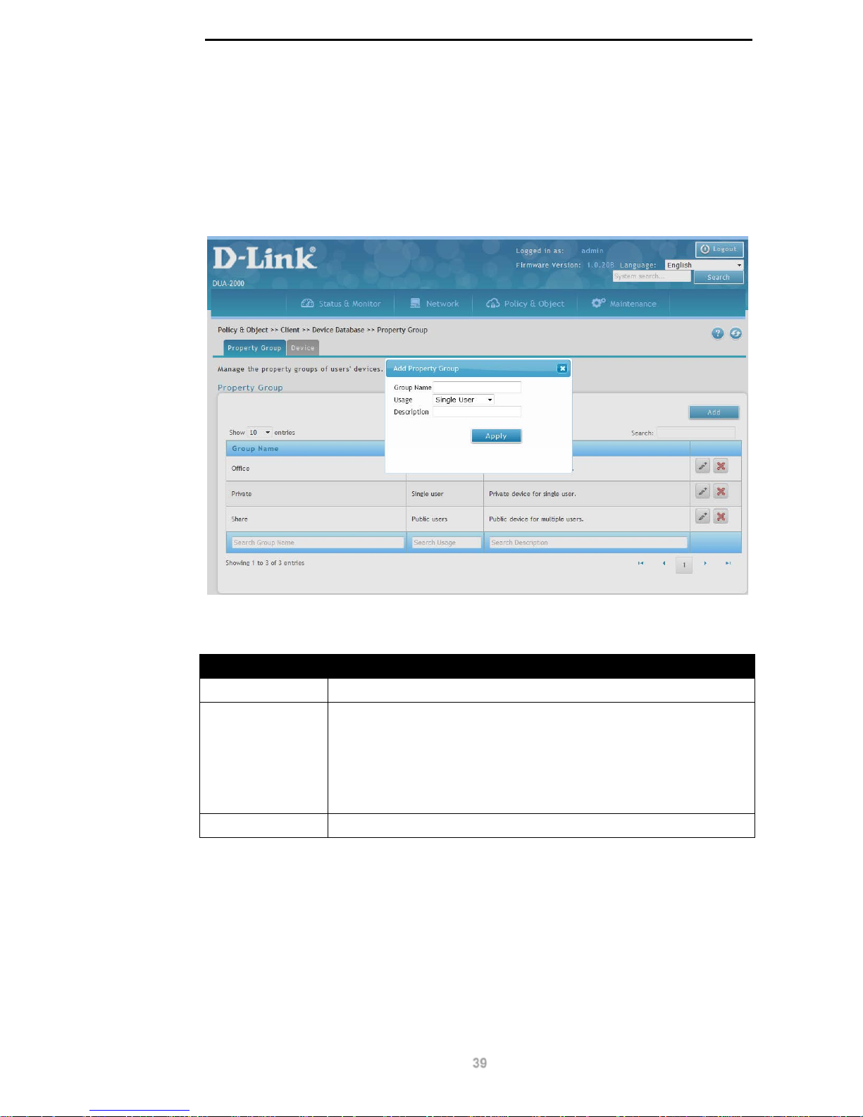
Add Property Group
Click the Add or Edit buttons to view the following window:
Figure 9-8 – Add Property Group
The following fields can be configured:
Field Description
Group Name
The name of the Property Group.
Usage
The device usage. This is a way of restricting the devices that a user
can log-in from and can be set to the following:
Single User. A personal device that is used by a single person.
Multiple users. A corporate device used by multiple people.
Public users. Any device that can be used by both corporate and
non-corporate users.
Description
The description of the Property Group.
Table 9-10 – Add Property Group
Click Apply to apply the settings.
Device
Devices are created on the Device page and consist of a MAC address, Device Type and
Property Group. The MAC address is used to uniquely identify a device. The Device Type is
used to classify the device in the Policy Rule and the Property Group is used to group
devices on the Account and Device page.
Page 45
D-Link DUA-2000 Policy Manager User Manual
40
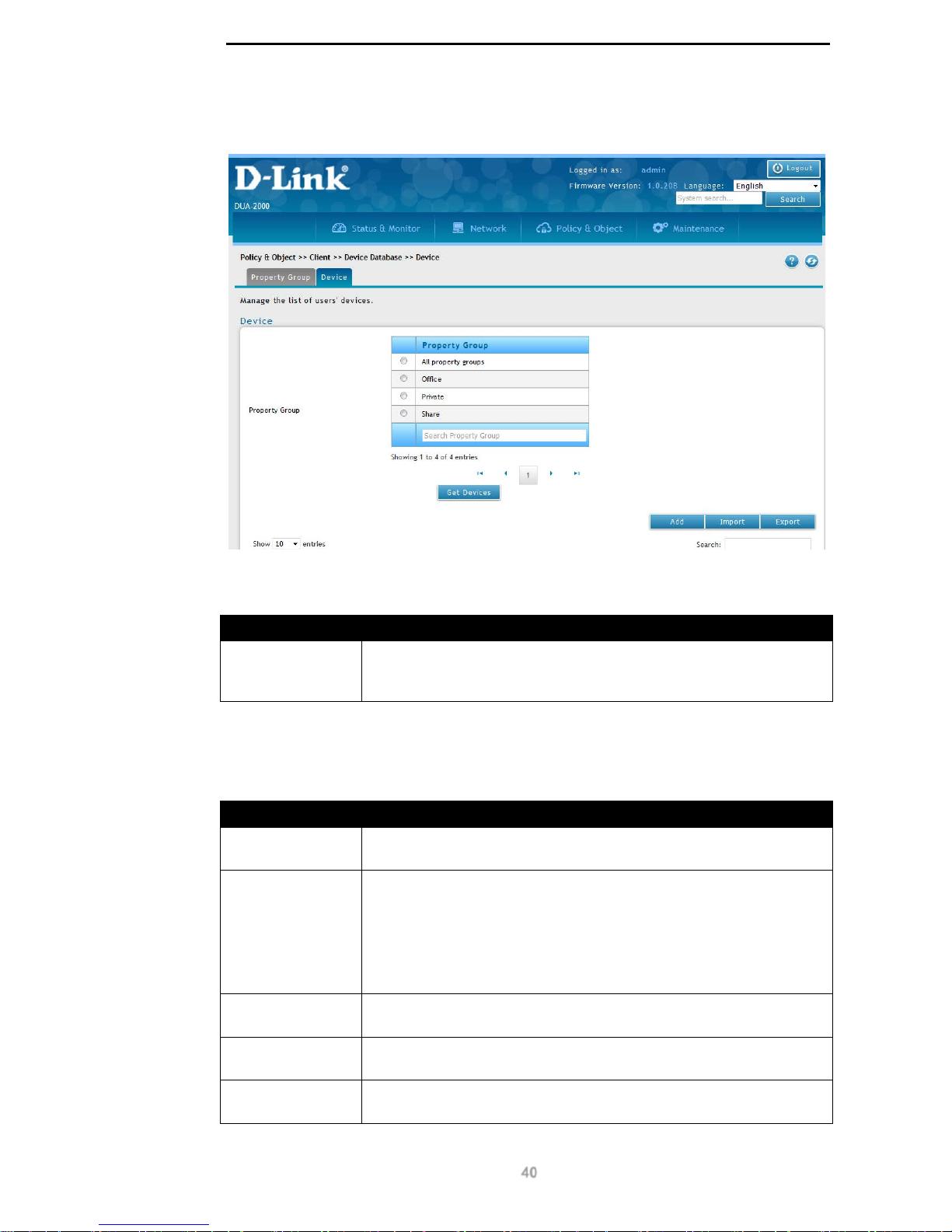
To get to the following page, browse to: Policy & Object >> Client >> Device Database
and click on the Device tab:
Figure 9-9 – Device
The following fields are available:
Field Description
Property Group
The Property Group to search for devices. The can be one of the
Property Groups on the Property Groups page, or All property
groups.
Table 9-11 – Device 1
Click Get Devices to search for devices.
The following fields are available:
Field Description
MAC Address
The MAC address of the device, in the format: xx:xx:xx:xx:xx:xx. This
is used to uniquely identify the device.
Device Type
The type of device. This is used by the Policy Rule and is another
parameter through which to authenticate devices. It can be set to:
Others. Use this to classify any device which is not a mobile phone or
laptop.
Mobile. Use this to classify a device as a mobile phone.
Laptop. Use this to classify a device as a laptop.
Property Group
This is used to group devices and define the device Usage (see the
Property Group section).
User Name
The user name of the user that the device is associated with (see the
Account section).
Group
The group the user name is associated with ( s ee the Account
section).
Table 9-12 – Device 2
Page 46
D-Link DUA-2000 Policy Manager User Manual
41
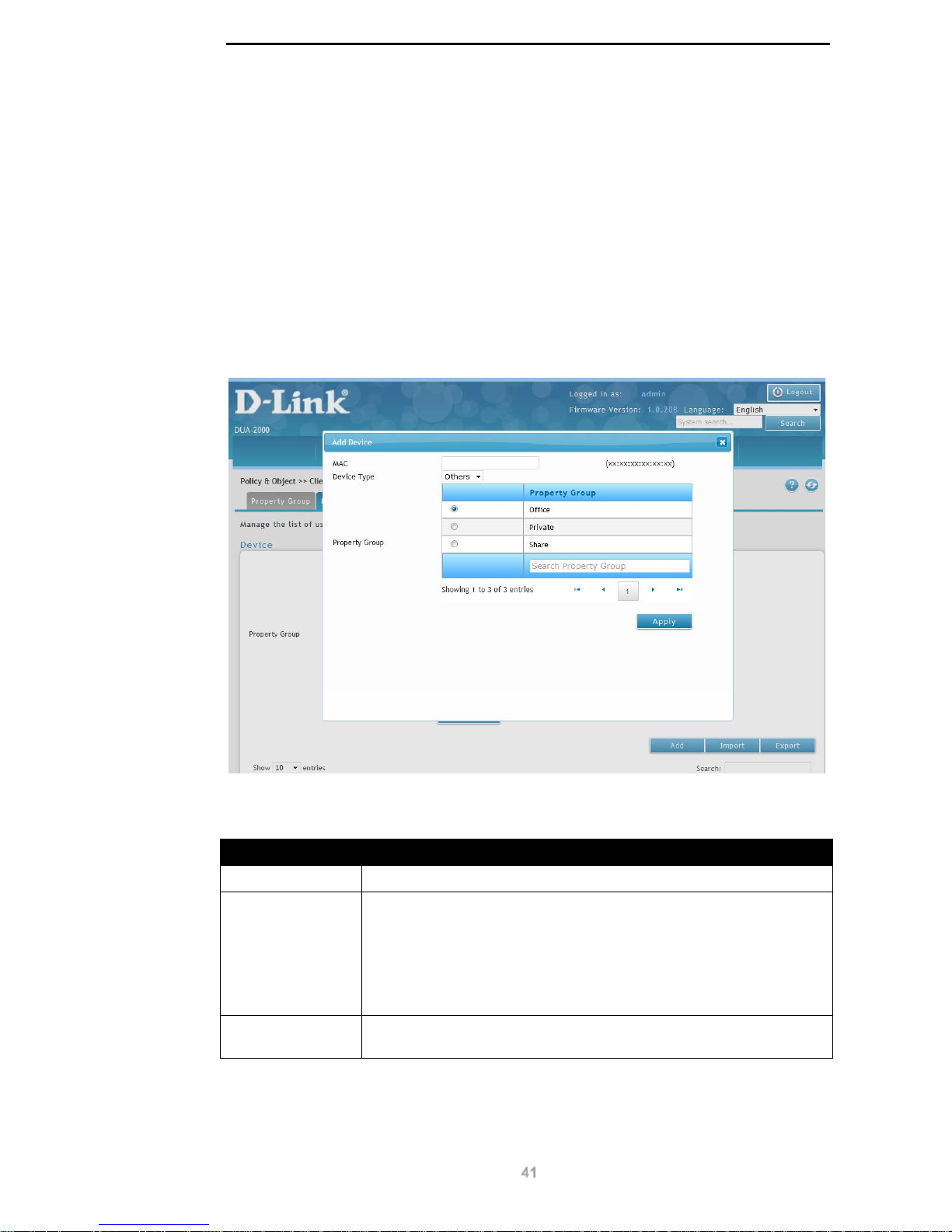
Click Add to add a Device.
Click Import to import a Device CSV file.
Click Export to ex port a Device CSV file.
Click Edit to edit existing Device settings.
Click Delete to delete a Device.
Add Device
Click the Add or Edit buttons to view the following window:
Figure 9-10 – Add Device
The following fields c an be conf igur ed:
Field Description
MAC Address
The MAC address of the device, in the format: xx:xx:xx:xx:xx:xx.
Device Type
The type of device. This is used by the Policy Rule and is another
parameter through which to authenticate devices. It can be set to:
Others. Use this to classify any device which is not a mobile phone or
laptop.
Mobile. Use this to classify a device as a mobile phone.
Laptop. Use this to classify a device as a laptop.
Property Group
This is used to group devices and define the device Usage on the
Property Group page.
Table 9-13 – Add Device
Click Apply to apply the settings.
Page 47
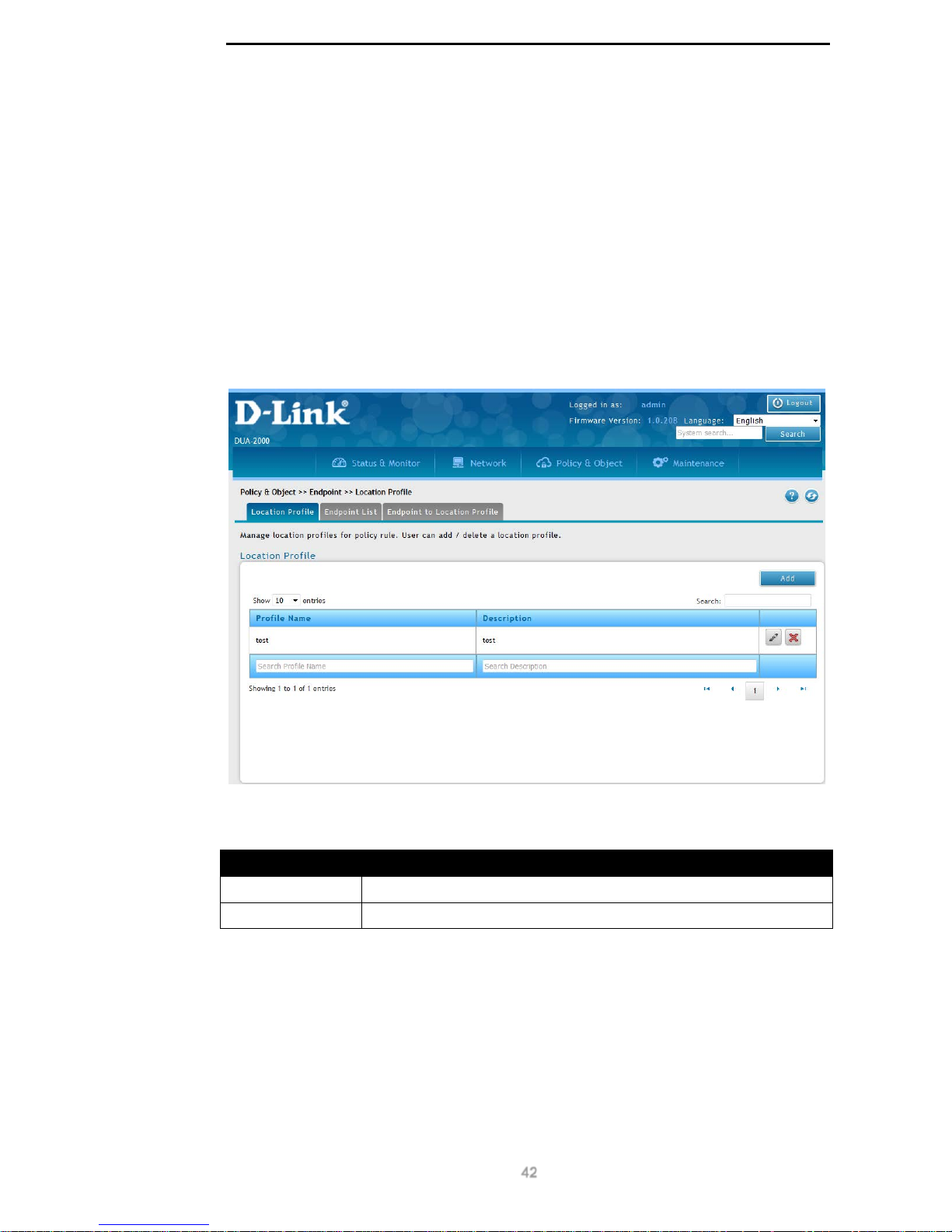
D-Link DUA-2000 Policy Manager User Manual
42
Endpoint
Location Profile
Location Profile
A Location Profile is a way of grouping Endpoints for form a location. A location is a group of
switch ports that are used to define where a client can authenticate from. An Endpoint can
have one port assigned to it in the case of a wireless AP or multiple ports assigned to it in
the case of a Layer 2 or 3 switch. This defines which wireless APs a client can authenticate
from and which switch ports a client can authenticate from, based on the Policy Rule.
To get to the following page, browse to: Policy & Object >> Endpoint >> Location Profile:
Figure 9-11 – Location Profile
The following fields are available:
Field Description
Profile Name
The name of the Locati on Prof ile.
Description
The description of the Location Profile.
Table 9-14 – Location Profile
Click Add to add a Location Profile.
Click Edit to edit existing Location Profile settings.
Click Delete to delete a Location Profile.
Add Location Profile
Click the Add or Edit buttons to view the following window:
Page 48
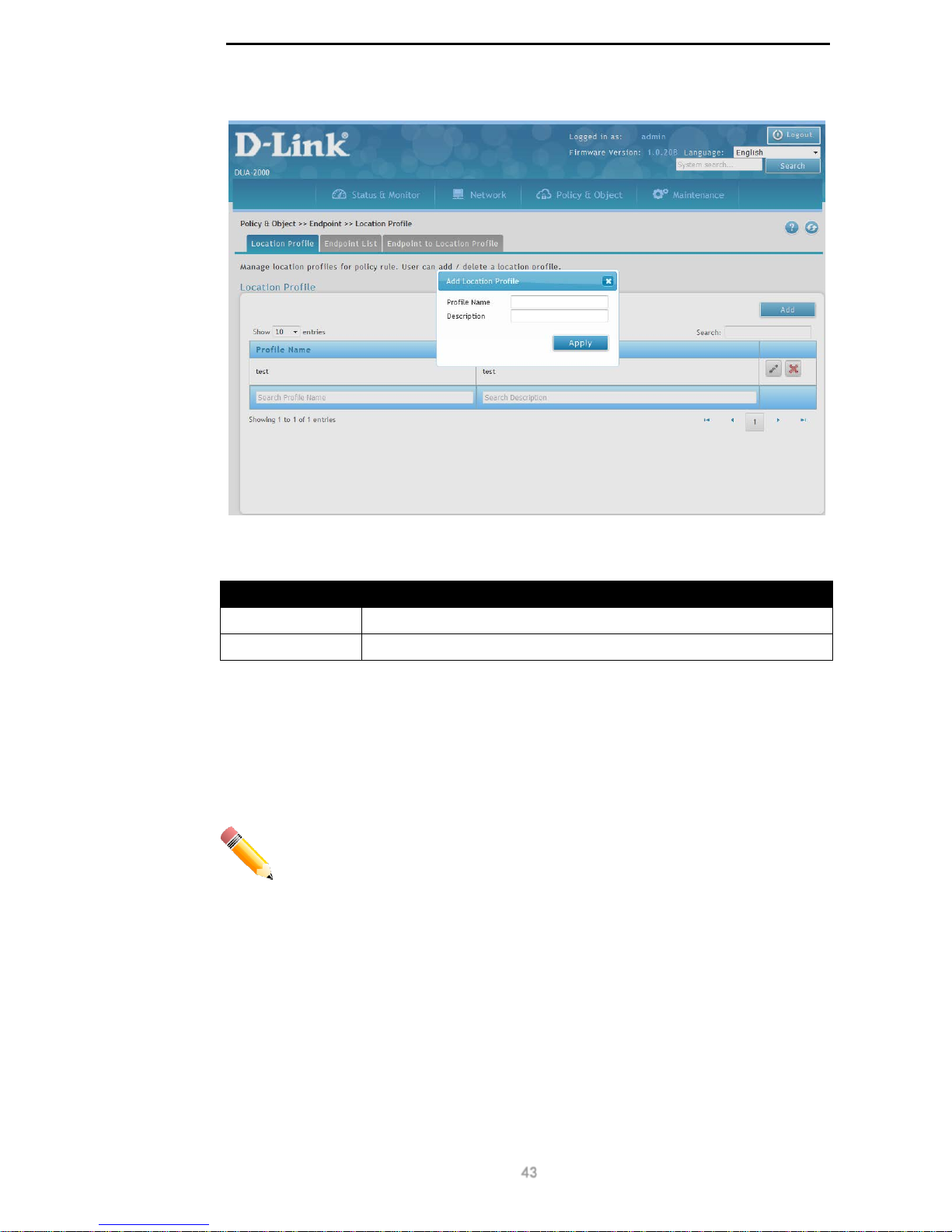
D-Link DUA-2000 Policy Manager User Manual
43
Figure 9-12 – Add Location Profile
The following fields can be configured:
Field Description
Profile Name
The name of the Locati on Prof ile.
Description
The description of the Location Profile.
Table 9-15 – Add Location Profile
Click Apply to apply the settings.
Endpoint List
The Endpoint List is a list of Endpoints that are assigned to the Location Profile. The
Endpoint List page can be used to add, scan, edit or delete Endpoints.
NOTE: A maximum of 10 Endpoints can be configured in one Location Profile.
To get to the following page, browse to: Policy & Object >> Endpoint >> Location Profile
and click on the Endpoint List tab:
Page 49
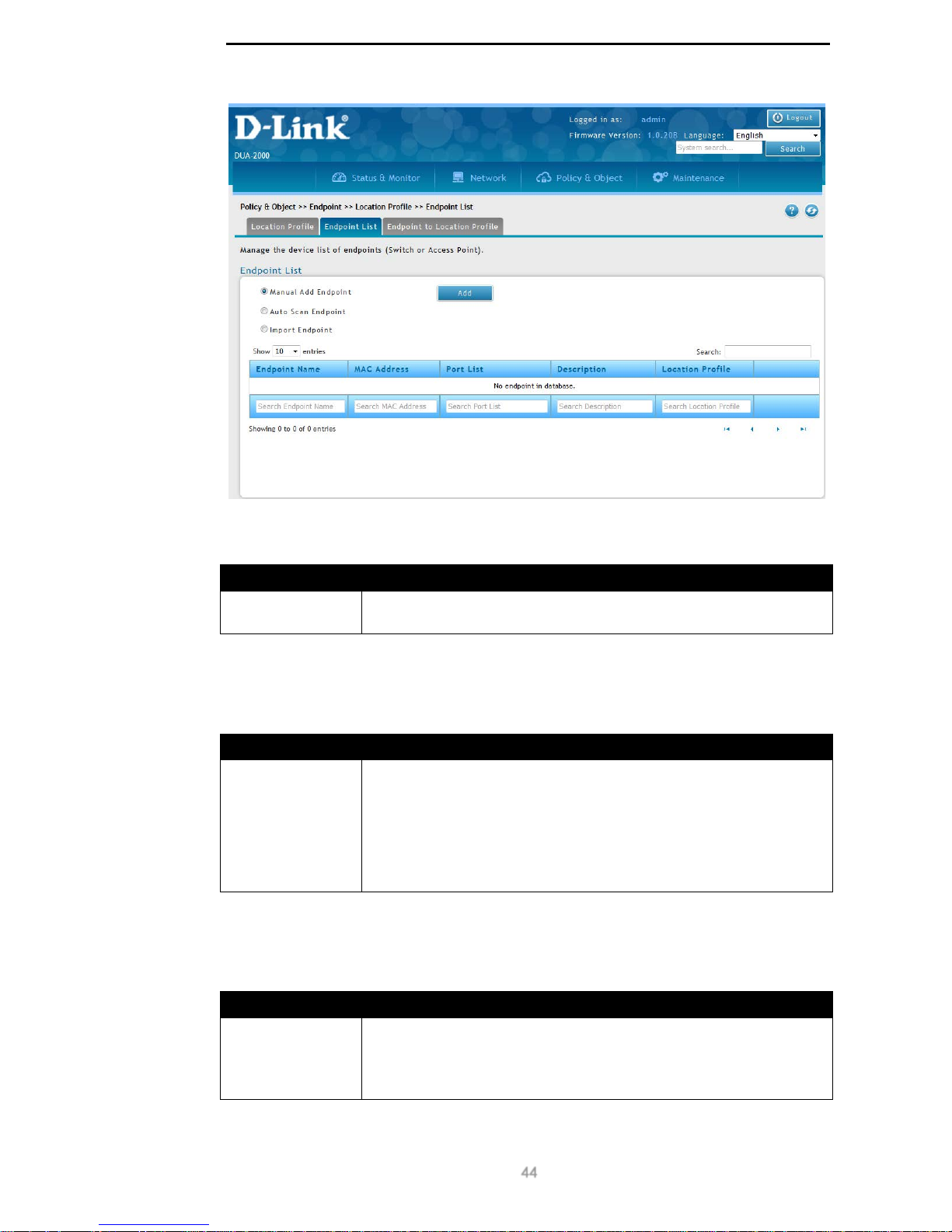
D-Link DUA-2000 Policy Manager User Manual
44
Figure 9-13 – Endpoint List
The following fields are available:
Field Description
Manual Add
Endpoint
Add an endpoint to the Endpoint List manually.
Table 9-16 – Endpoint List 1
Click Add to manually add an endpoint.
The following fields are available:
Field Description
Auto Scan
Endpoint
Scan the subnet for endpoints to add to the Endpoint List.
Any endpoints that have not already been added to the Endpoint List
will display a green circle in the search results, any endpoints that
have already been added to the Endpoint List will display a red circle
in the search results. Click the green circle to add the device to the
Endpoint List. The MAC Ad d r e s s field will be populated with th e MAC
address of the discovered device.
Table 9-17 – Endpoint List 2
Click Scan to scan the subnet for endpoints.
The following fields are available:
Field Description
Import Endpoint
Import endpoints to the Endpoint List using a CSV file.
Click Browse to browse for a local copy of the CSV files. Tick the
First line header box if the first line of the CSV file is the field header
and you do not want to import these values.
Table 9-18 – Endpoint List 3
Click Import to import a list of endpoints from a CSV file.
Page 50
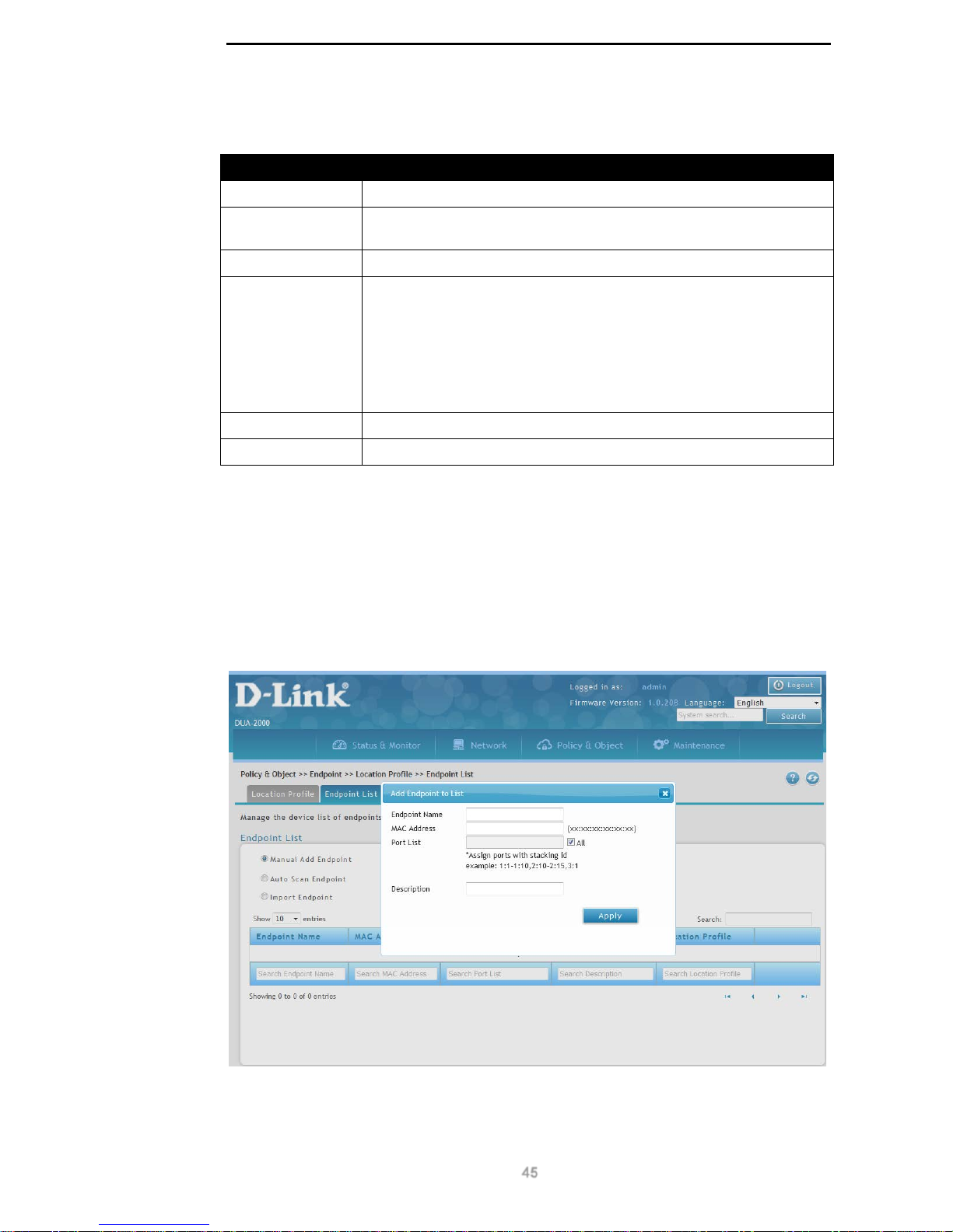
D-Link DUA-2000 Policy Manager User Manual
45
The following fields are available:
Field Description
Endpoint Name
The name of the Endpoint. This can be a switch or wireless AP.
MAC Address
The MAC address of the Endpoint, in the format: xx:xx:xx:xx:xx:xx.
This is the MAC address of the switch or wireless AP.
IP Address
The IP address of the Endpoint.
Port List
The ports on the switch or wireless AP that are associated with the
Endpoint.
For example, switch ports 1-4 on switch 1 in the stack could be one
location and port 5 on switch 2 in the stack could be another location.
The Port List is comma separated and is in the format: <switch stack
ID>:<port ID>. A hyphen (‘-’) can be used to specify a range. For
example: 1:1-1:4,2:5.
Description
The description of the Endpoint.
Location Profile
The Location Profile this En dpo int has been add ed to.
Table 9-19 – Endpoint List 4
Click Edit to edit existing Endpoint List settings.
Click Delete to delete an Endpoint List.
Add Endpoint to List
The following window displa ys when manually adding an endpoint, clicking the green circle
in the scan results when scanning the subnet for devices, or editing an existing endpo int in
the Endpoint List:
Figure 9-14 – Add Endpoint to List
The following fields can be configured:
Page 51
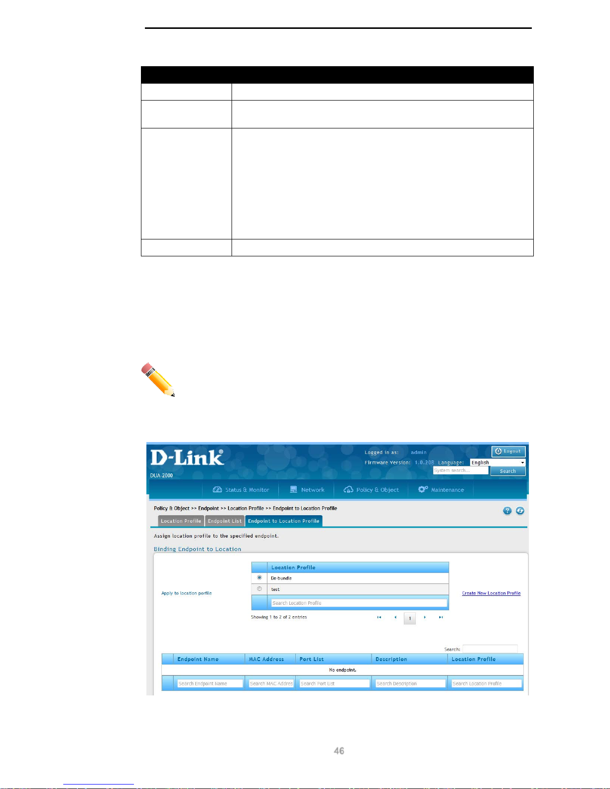
D-Link DUA-2000 Policy Manager User Manual
46
Field Description
Endpoint Name
The name of the Endpoint. This can be a switch or wireless AP.
MAC Address
The MAC address of the Endpoint, in the format: xx:xx:xx:xx:xx:xx.
This is the MAC address of the switch or wireless AP.
Port List
The ports on the switch or wireless AP that are associated with the
Endpoint.
The MAC Address identifies the Endpoint and the switch stack ID and
port number identify the ports that are associated with the Endpoint.
For example, switch ports 1-4 on switch 1 in the stack could be one
location and port 5 on switch 2 in the stack could be another location.
The Port List is comma separated and is in the format: <switch stack
ID>:<port ID>. A hyphen (‘-’) can be used to specify a range. For
example: 1:1-1:4,2:5.
Description
The description of the Endpoint.
Table 9-20 – Add Endpoint to List
Click Apply to apply the settings.
Endpoint to Location Profile
This is used to bind an Endpoint to a Locati on Prof il e. It can also be used to create new
Location Profiles.
NOTE: A maximum of 10 Endpoints can be configured in one Location Profile.
To get to the following page, browse to: Policy & Object >> Endpoint >> Location Profile
and click on the Endpoint to Location Profile tab:
Figure 9-15 – Endpoint to Location Profile
The following fields are available:
Page 52
D-Link DUA-2000 Policy Manager User Manual
47
Field Description
Location Profile
The Location Profile to associate the Endpoint with. This is taken from
the Location Profile page.
Table 9-21 – Endpoint to Location Profile 1
Click Create New Location Profile to be taken to the Location Profile page.
The following fields are available:
Field Description
Endpoint Name
The name of the Endpoint. This can be a switch or Wireless AP.
MAC Address
The MAC address of the Endpoint, in the format: xx:xx:xx:xx:xx:xx.
This is the MAC address of the switch or wireless AP.
IP Address
The IP address of the Endpoint.
Port List
The ports on the switch that this Location Profile applies to.
The Port List is comma separated and is in the format: <switch stack
ID>:<port ID>. A hyphen (‘-’) can be used to specify a range. For
example: 1:1-1:4,2:5.
Description
The description of the Endpoint.
Location Profile
The Location Profile this Endpoint has been added to.
Table 9-22 – Endpoint to Location Profile 2
Select the check-boxes for the endpoints you wish to add to a Location Profile and choose
the Location Profile from the Location Profile menu.
Click Save to save the changes made.
Click Cancel to revert the settings to their previous state.
Authorization
Authorization Profile
Authorization Profile
The Authorization Profil e is applied to the Policy Rule and is applied to clients as a result of
the authentication process. It contains Layer 2 and 3 settings such as: VLAN ID, bandwidth
restrictions, Quality of Service (QoS) features, session timeout values and Access Control
List (ACL) functions.
To get to the following page, browse to: Policy & Object >> Authorization >>
Authorization Profile:
Page 53
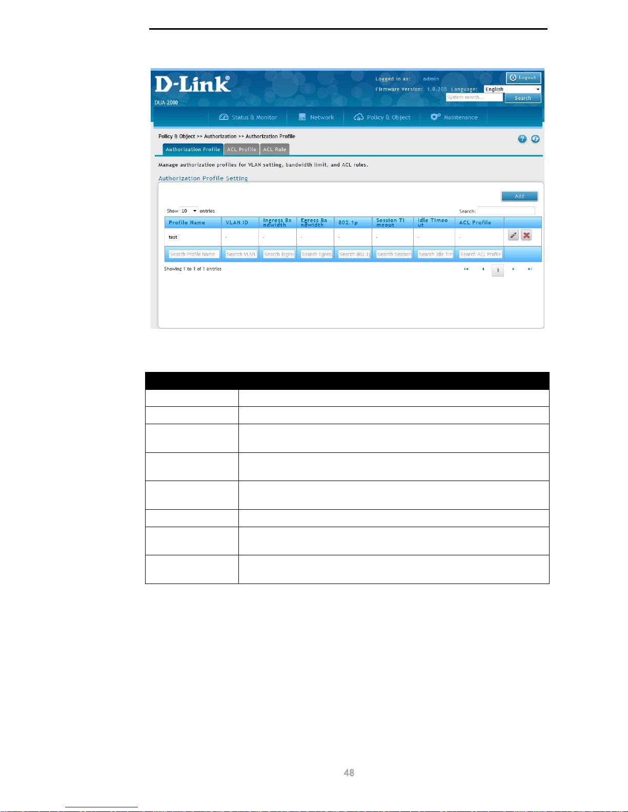
D-Link DUA-2000 Policy Manager User Manual
48
Figure 9-16 – Authorization Profile
The following fields are available:
Field Description
Profile Name
The name of the Author i zation Profile.
VLAN ID
The VLAN ID or number that the Authori zation Profile applies to.
Ingress
Bandwidth
The ingress or download bandwidth limit for the clients that the
Authorization Profile applies to (measured in bps).
Egress
Bandwidth
The egress or upload bandwidth limit for the clients that the
Authorization Profile applies to (measured in bps).
802.1p
The Layer 2 Class of Service level that is applied to traffic from clients
that the Authorization Profile applies to.
Session Timeout
The maximum length of the client session (measured in seconds).
Idle Timeout
The length of time to keep the client session active if not activity is
detected, before ending the session (measured in seconds).
ACL Profile
The ACL Profile applied to the Authori zat ion Prof il e. This is defined in
the ACL Profile tab and ACL Rule tab.
Table 9-23 – Authorization Profile
Click Add to add an Authorization Profile.
Click Edit to edit existing Authoriza ti on Prof ile settings.
Click Delete to delete an Authorization Prof ile.
Add Authorization Profil e
Click the Add or Edit buttons to view the following window:
Page 54
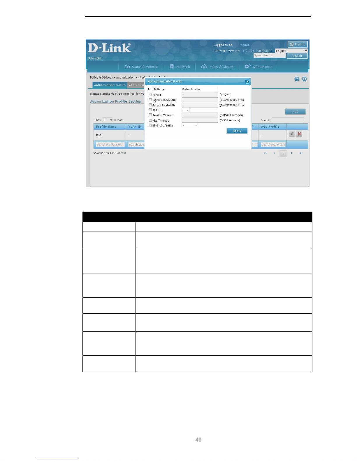
D-Link DUA-2000 Policy Manager User Manual
49
Figure 9-17 – Add Authorization Profile
The following fields can be configured:
Field Description
Profile Name
The name of the Author i zation Profile.
VLAN ID
The VLAN ID or number that the Authori zation Profile applies to.
Range: 1 - 4094.
Ingress
Bandwidth
The ingress or download bandwidth limit for the clients that the
Authorization Profile applies to.
Range: 1 – 409 600 000 bps (1 bps – 409.6 Mbps).
Egress
Bandwidth
The egress or upload bandwidth limit for the clients that the
Authorization Profile applies to.
Range: 1 – 409 600 000 bps (1 bps – 409.6 Mbps).
802.1p
The Layer 2 Class of Service level that is applied to traffic from clients
that the Authorization Profile applies to.
Session Timeout
The maximum length of the client session.
Range: 0 - 86400 seconds.
Idle Timeout
The length of time to keep the client sess ion ac tive if not activit y is
detected, before ending the session.
Range: 0 - 900 seconds.
ACL Profile
The ACL Profile applied to the Authori zat ion Prof il e. This is defined in
the ACL Profile tab and ACL Rule tab.
Table 9-24 – Add Authorization Profile
Click Apply to apply the settings.
ACL Profile
The ACL Profile is an ordered list of ACL Rules. They can be applied to Authorization
Profiles and form the Layer 2 and 3 settings applied to a client after authentication.
Page 55
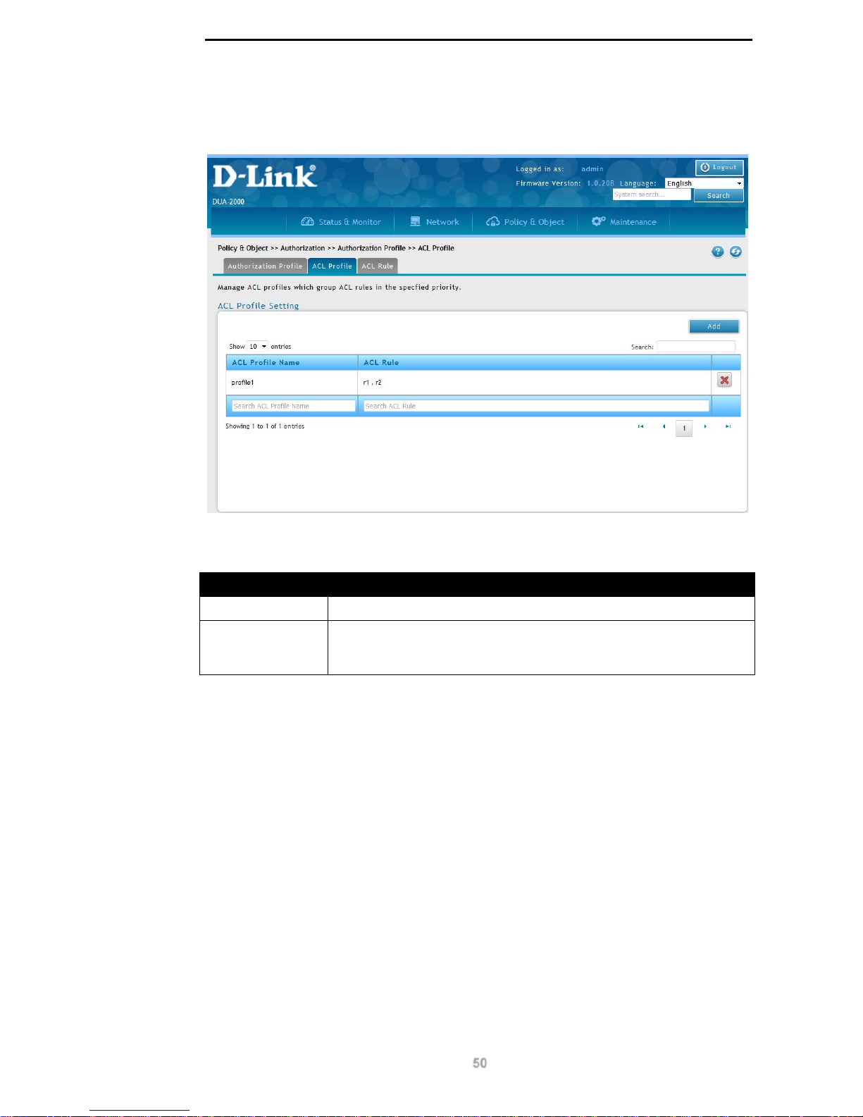
D-Link DUA-2000 Policy Manager User Manual
50
To get to the following page, browse to: Policy & Object >> Authorization >>
Authorization Profile and click on the ACL Profile tab:
Figure 9-18 – ACL Profile
The following fields are avail able:
Field Description
ACL Profile Name
The name of the ACL Pr of il e.
ACL Rule
This is the list of the ACL Rules in the ACL Profile, with the ACL
Profile on the left being matched first and the ACL Profile on the right
being matched last.
Table 9-25 – ACL Profile
Click Add to add an ACL Profile.
Click Delete to delete an ACL Profile.
Add ACL Profile
Click the Add button to view the following window:
Page 56
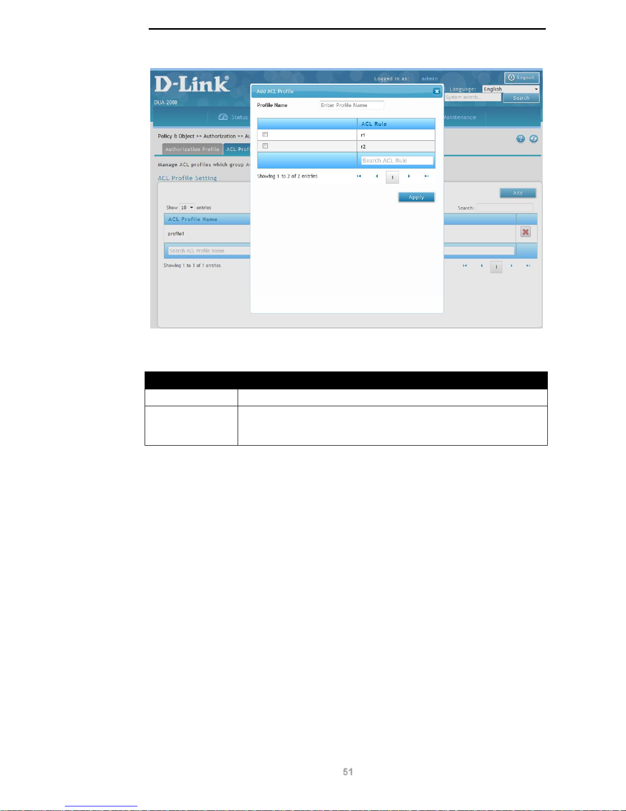
D-Link DUA-2000 Policy Manager User Manual
51
Figure 9-19 – Add ACL Profile
The following fields can be configured:
Field Description
Profile Name
The name of the ACL Pr of il e.
ACL Rule
This is an ACL Rule created on the ACL Rule page. The rules are
numbered from 1 to 10, with 1 being matched first and 10 being
matched last.
Table 9-26 – Add ACL Profile
Click Apply to apply the settings.
ACL Rule
The ACL Rule can permit or deny traffic based on the destination MAC or IP address and
Layer 4 information such as TCP and UDP port number. A mask can also be defined to
match TCP or UDP port numbers in a range.
To get to the following page, browse to: Policy & Object >> Authorization >>
Authorization Profile and click on the ACL Rule tab:
Page 57
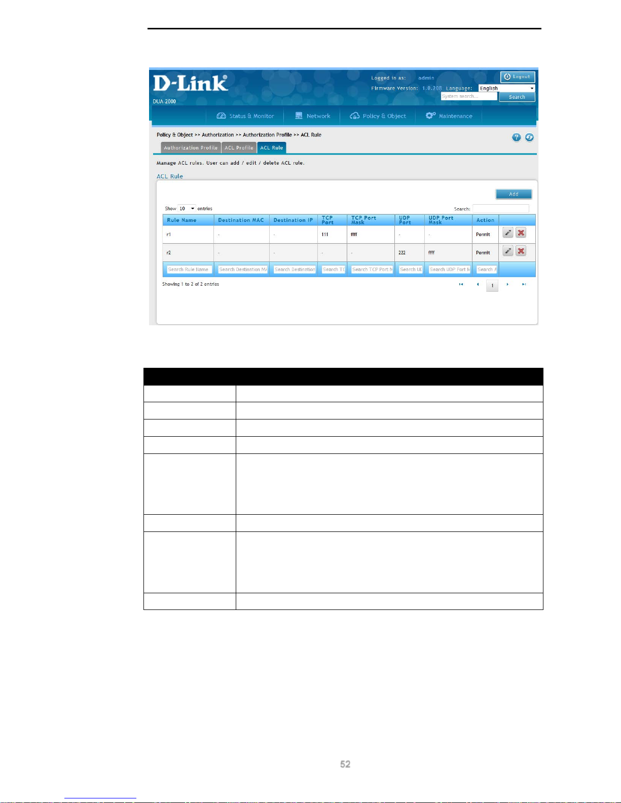
D-Link DUA-2000 Policy Manager User Manual
52
Figure 9-20 – ACL Rule
The following fields are available:
Field Description
Rule Name
The name of the ACL Rule.
Destination MAC
The destination MAC address that the rule matches.
Destination IP
The destination IP address that the rule matches.
TCP Port
The destination TCP port that the rule matches.
TCP Port Mask
A mask defining the range of TCP ports allowed, in the range: ‘0000’ ‘ffff’. If ‘ffff’ is defined, then only the port specified is allowed. If the
mask is not ‘ffff’, then a logical AND operation is performed between
the port number (in hex notation) and the port mask (also in hex
notation).
UDP Port
The destination UDP port that the rule matches.
UDP Port Mask
A mask defining the range of UDP ports allowed, in the range: ‘0000’ ‘ffff’. If ‘ffff’ is defined, then only the port specified is allowed. If the
mask is not ‘ffff’, then a logical AND operation is performed between
the port number (in hex notation) and the port mask (also in hex
notation).
Action
Permit or deny the packet.
Table 9-27 – ACL Rule
Click Add to add an ACL Rule.
Click Edit to edit existing ACL Rule settings.
Click Delete to delete an ACL Rule.
Add ACL Rule
Click the Add or Edit buttons to view the following window:
Page 58
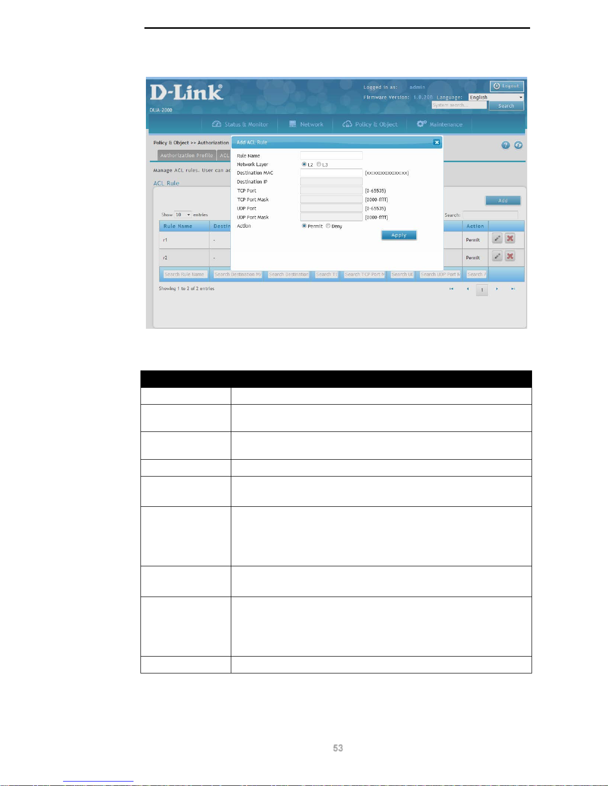
D-Link DUA-2000 Policy Manager User Manual
53
Figure 9-21 – Add ACL Rule
The following fields can be configured:
Field Description
Rule Name
The name of the ACL Rule.
Network Layer The network layer that the rule applies to. Select L2 (Layer 2) or L3
(Layer 3).
Destination MAC
The destination MAC address that the rule applies to. This is a 48-bit
MAC address in the format: xx:xx:xx:xx:xx:xx.
Destination IP
The destination IP address that the rule applies to.
TCP Port
The destination TCP port that the rule matches.
Range: 0 – 65535.
TCP Port Mask
A mask defining the range of TCP ports allowed, in the range: ‘0000’ ‘ffff’. If ‘ffff’ is defined, then only the port specified is allowed. If the
mask is not ‘ffff’, then a logical AND operation is performed between
the port number (in hex notation) and the port mask (also in hex
notation).
UDP Port
The destination UDP port that the rule matches.
Range: 0 – 65535.
UDP Port Mask
A mask defining the range of UDP ports allowed, in the range: ‘0000’ ‘ffff’. If ‘ffff’ is defined, then only the port specified is allowed. If the
mask is not ‘ffff’, then a logical AND operation is performed between
the port number (in hex notation) and the port mask (also in hex
notation).
Action Permit or deny the packet. This can be set to Permit or Deny.
Table 9-28 – Add ACL Rule
Click Apply to apply the settings.
Page 59
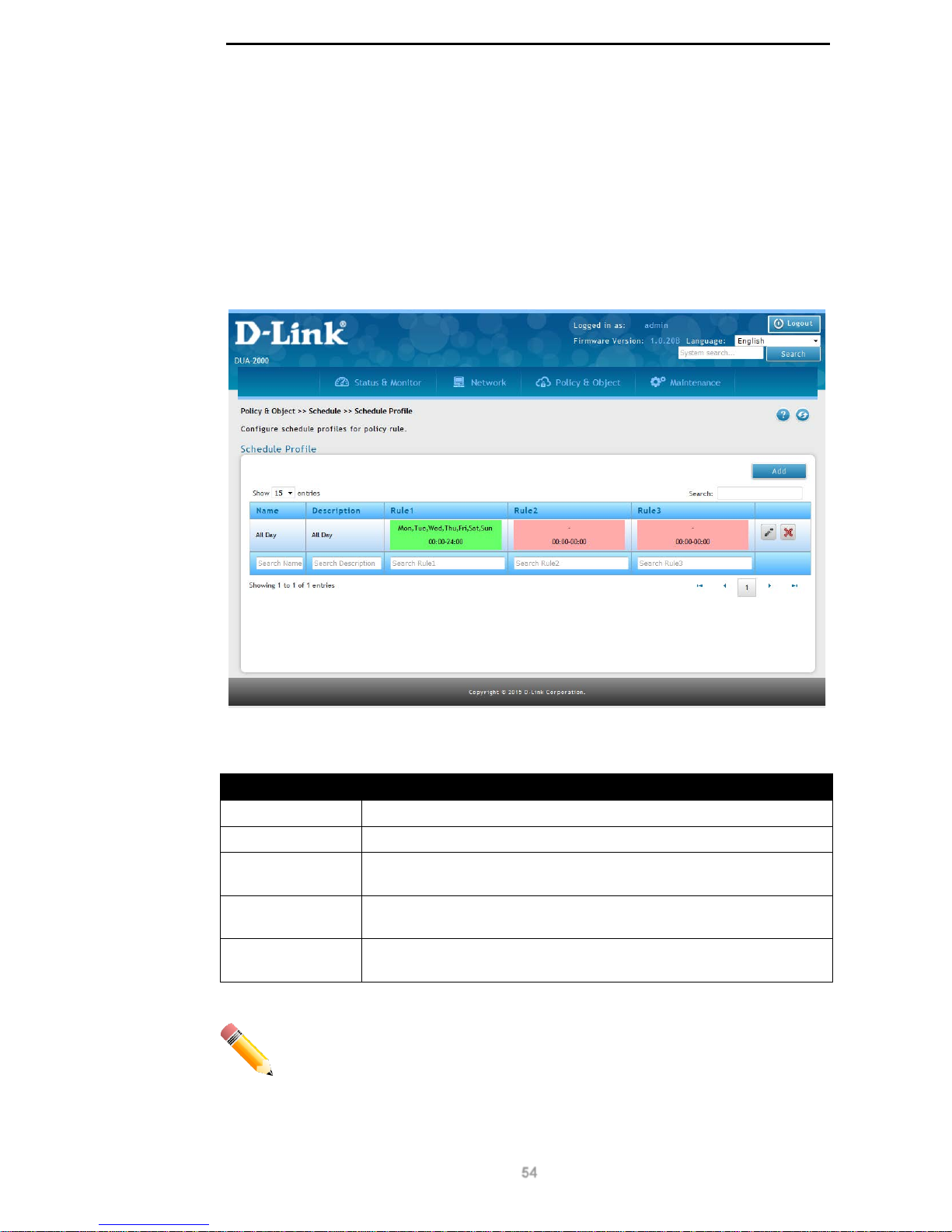
D-Link DUA-2000 Policy Manager User Manual
54
Schedule
Schedule Profile
A Schedule Profile is applied to the Policy Rule and is a way of defining when a Policy Rule
is active. If a Policy Rule is not active then it is not available to authenticate clients and client
users and devices are denied access to the network.
To get to the following page, browse to: Policy & Object >> Schedule >> Schedule Profile:
Figure 9-22 – Schedule Profile
The following fields are available:
Field Description
Name
The name of the Schedule Profile.
Description
The description of the Schedule Profile.
Rule1
Rule 1 in the Schedule Profile. A green background means it is
enabled and a red background means it is disabled.
Rule2
Rule 2 in the Schedule Profile. A green background means it is
enabled and a red background means it is disabled.
Rule3
Rule 3 in the Schedule Profile. A green background means it is
enabled and a red background means it is disabled.
Table 9-29 – Schedule Profile
NOTE: In order to prevent any problems with the operation of the Schedule
Profile, make sure none of the schedules in the Schedule Profile overlap.
Click Add to add a Schedule Profile.
Click Edit to edit existi ng S c hedu le Prof ile set tings .
Page 60
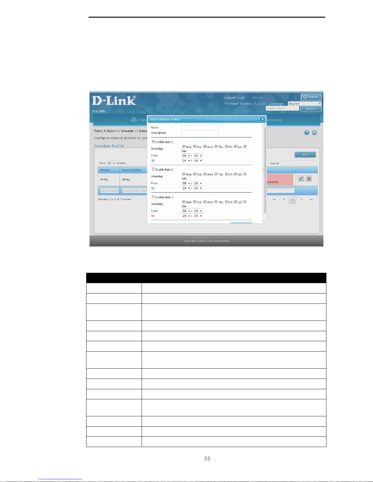
D-Link DUA-2000 Policy Manager User Manual
55
Click Delete to delete a Schedule Profile.
Add Schedule Profile
Click the Add or Edit buttons to view the following window:
Figure 9-23 – Add Schedule Profile
The following fields can be configured:
Field Description
Name
The name of the Schedule Profile.
Description
The description of the Schedule Profile.
Enabled Rule 1
Tick this box to enable the rule in the Schedule Profile and un-tick it to
disable it.
Weekday
The day of the week that this schedule applies to.
From
The start time of the schedule, measured in 24 hour format.
To
The end time of the schedule, measured in 24 hour format.
Enabled Rule 2
Tick this box to enable the rule in the Schedule Profile and un-tick it to
disable it.
Weekday
The day of the week that this schedule applies to.
From
The start time of the schedule, measured in 24 hour format.
To
The end time of the schedule, measured in 24 hour format.
Enabled Rule 3
Tick this box to enable the rule in the Schedule Profile and un-tick it to
disable it.
Weekday
The day of the week that this schedule applies to.
From
The start time of the schedule, measured in 24 hour format.
To
The end time of the schedule, measured in 24 hour format.
Page 61

D-Link DUA-2000 Policy Manager User Manual
56
Table 9-30 – Add Schedule Profile
Click Apply to apply the settings.
Page 62
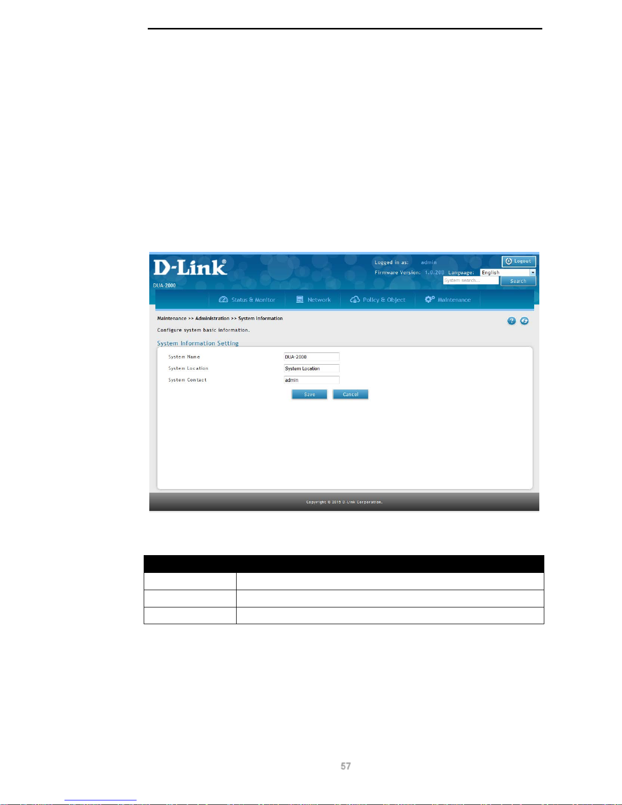
D-Link DUA-2000 Policy Manager User Manual
57
9. Maintenance
Administration
System Information
This can be used to set the system management information, such as hostname, location
and system contact information.
To get to the following page, browse to: Maintenance >> Administration >> System
Information:
Figure 10-1 – System Information
The following fields are available:
Field Description
System Name
The hostname of the Policy Manager.
System Location
The location of the Pol icy Manager.
System Contact
The contact information for the Policy Manager .
Table 10-1 – System Information
Click Save to save the changes made.
Click Cancel to revert the settings to their previous state.
Page 63
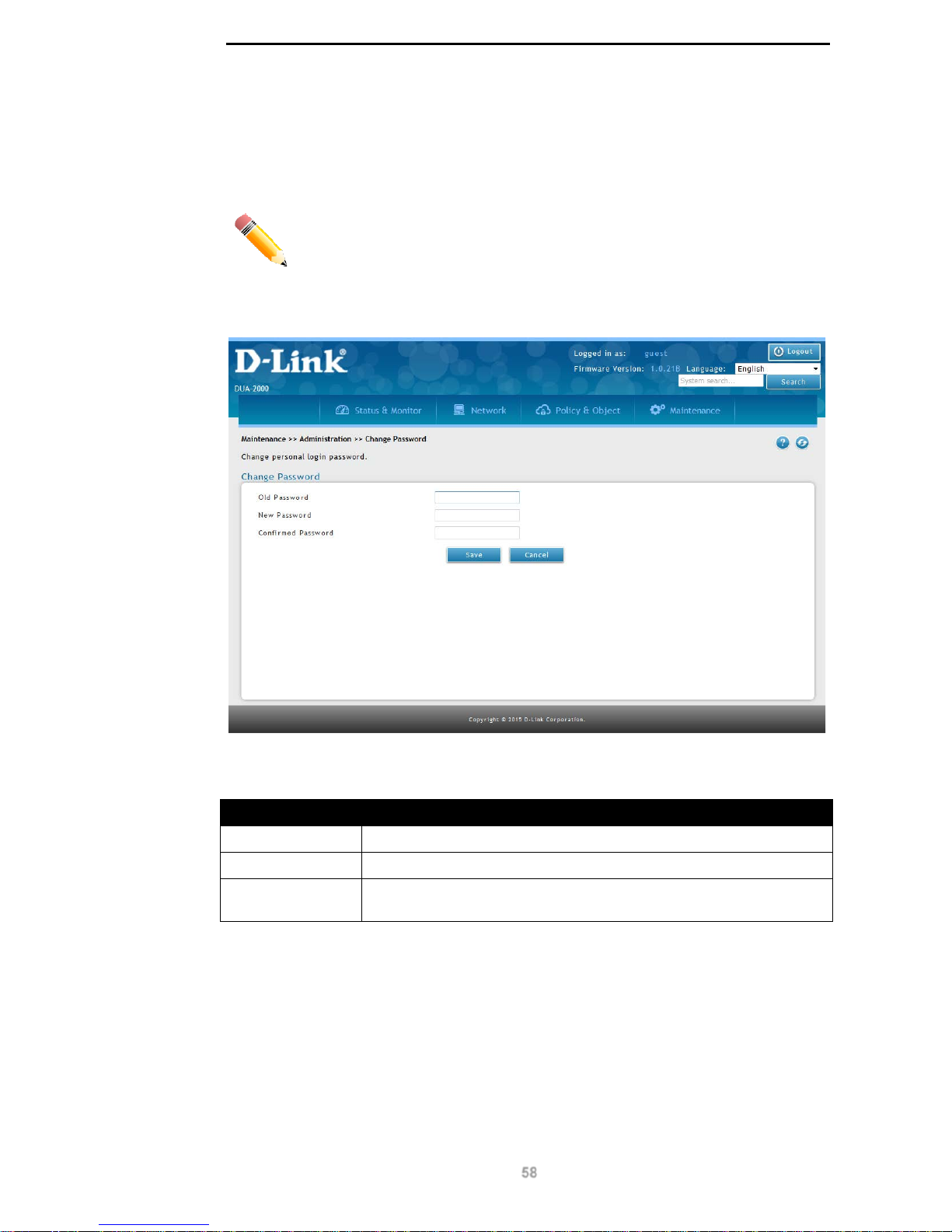
D-Link DUA-2000 Policy Manager User Manual
58
Change Password
This page allows a guest user to change their password.
NOTE: This page is only available to users logged-in as a guest.
To get to the following page, browse to: Maintenance >> Administration >> Change
Password:
Figure 10-2 – Change Password
The following fields are available:
Field Description
Old Password
The existing password for the guest user.
New Password
The new password for the guest user.
Confirmed
Password
The confirmed password for the guest user.
Table 10-2 – Change Password
Click Save to save the changes made.
Click Cancel to revert the settings to their previous state.
System Account
This is used to add, edit or delete system accounts, which can be used to administer the
system, allow the ability to create guest accounts, or log-in as a guest.
Page 64
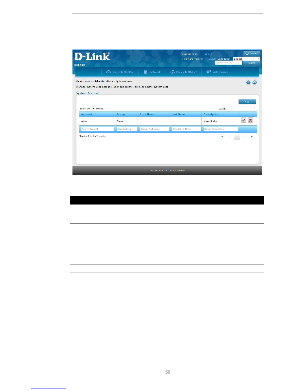
D-Link DUA-2000 Policy Manager User Manual
59
To get to the following page, browse to: Maintenance >> Administration >> System
Account:
Figure 10-3 – System Account
The following fields are available:
Field Description
Account
This is the username of the system account. This is local to the Policy
Manager only and is not integrated with any external authentication
sources.
Group
The group that the user is in. This can be:
Admin. This permission level has access to all parts of the system
and can change the system configuration.
Guest. This permission level is only able to view the system
configuration and cannot make any changes.
Fisrt Name
The first name of the user.
Last Name
The last name of the user.
Description
The description of the user.
Table 10-3 – System Account
Click Add to add a System Account.
Click Edit to edit existing System Account settings.
Click Delete to delete a System Account.
Add System Account
Click the Add or Edit buttons to view the following window:
Page 65
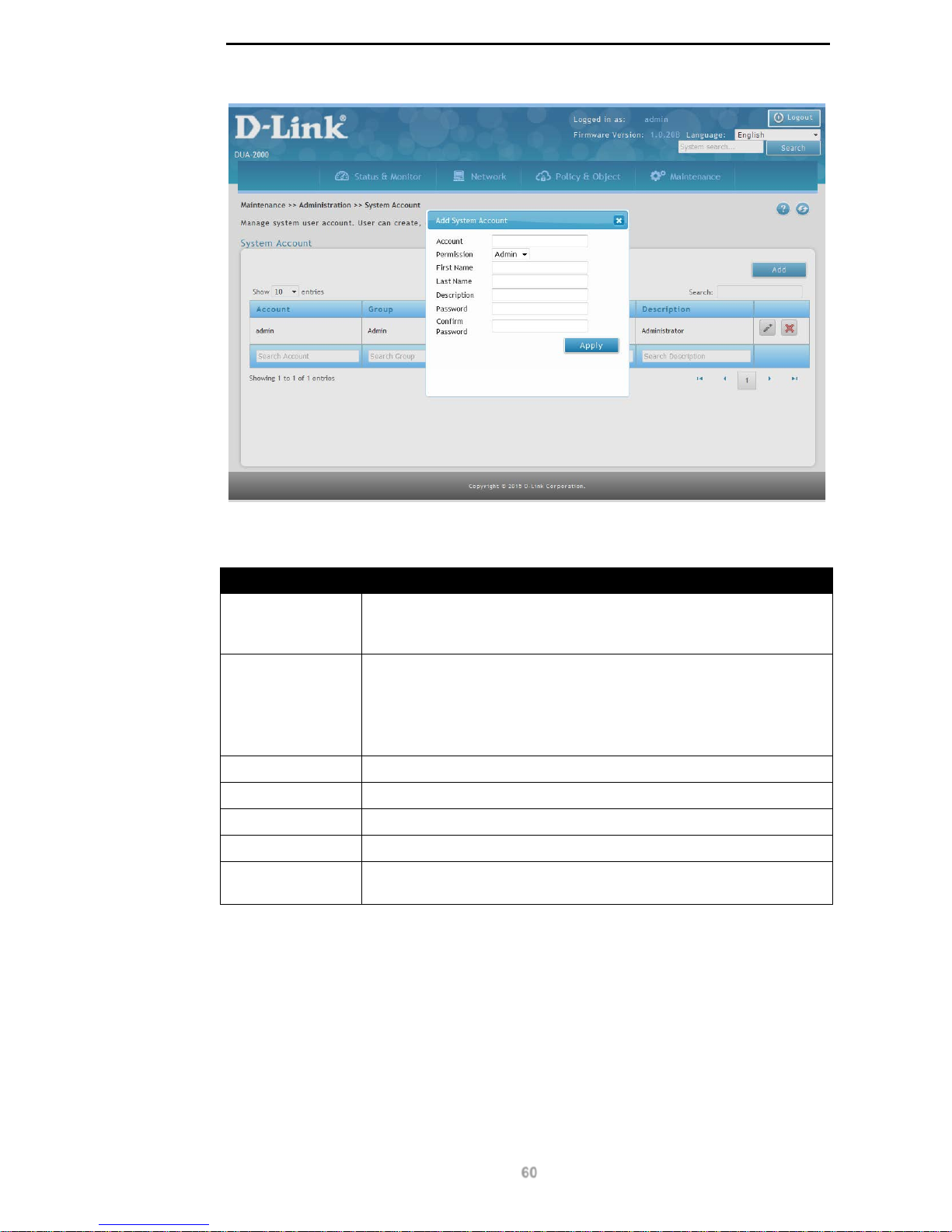
D-Link DUA-2000 Policy Manager User Manual
60
Figure 10-4 – Add System Account
The following fields can be configured:
Field Description
Account
This is the username of the system account. This is local to the Policy
Manager only and is not integrated with any external authentication
sources.
Permission
The group that the user is in. This can be:
Admin. This permission level has access to all parts of the system
and can change the system configuration.
Guest. This permission level is only able to view the system
configuration and cannot make any changes.
First Name
The first name of the user.
Last Name
The last name of the user.
Description
The description of the user.
Password
The password for the user.
Confirm
Password
The confirmed password for the user.
Table 10-4 – Add System Account
Click Apply to apply the settings.
Date and Time
This is used to set the date and time on the system. It can either be set locally or by using a
Simple Network Time Protocol (SNTP) reference.
To get to the following page, browse to: Maintenance >> Administration >> Date and
Time:
Page 66
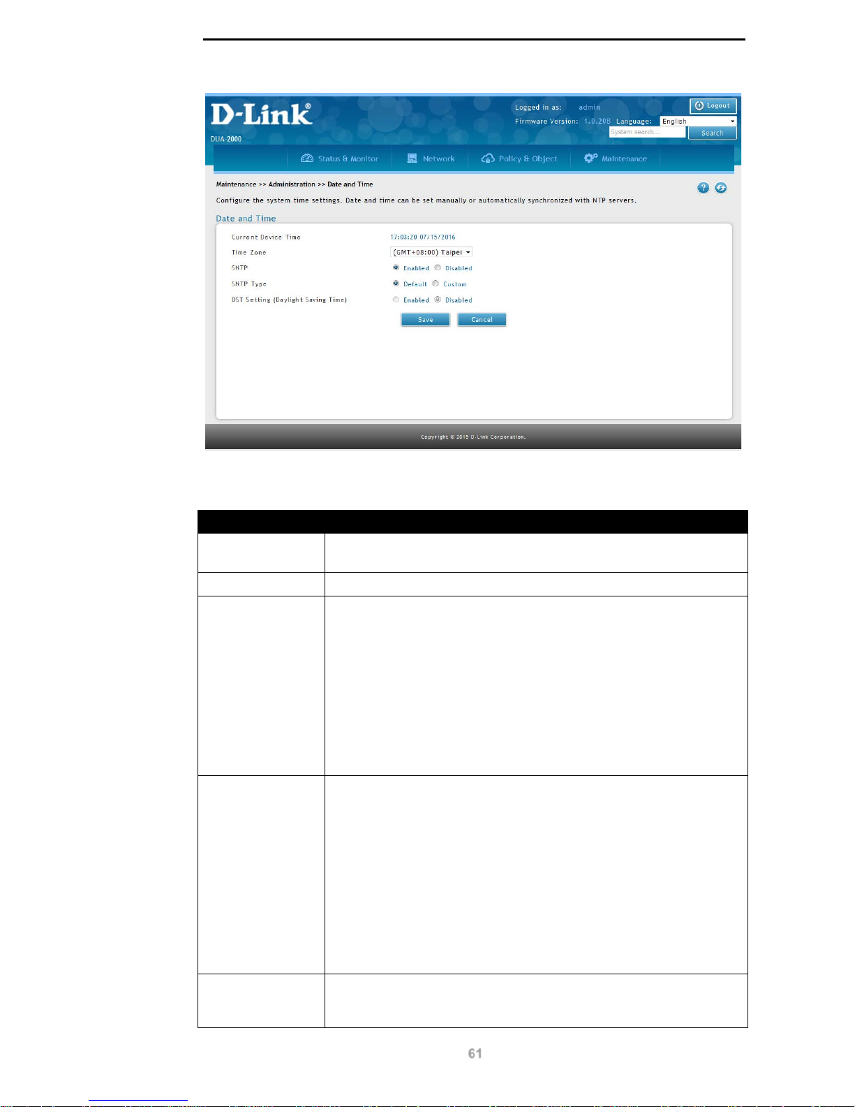
D-Link DUA-2000 Policy Manager User Manual
61
Figure 10-5 – Date and Time
The following fields are available:
Field Description
Current Device
Time
The current system time, in the format: HH:MM:SS MM/DD/YYYY.
Time Zone
The system time zone.
SNTP
The Simple Network Time Protocol (SNTP) status. This can be set to:
Enabled. The SNTP servers are accessible by clicking the Custom
option of the SNTP Type field.
Disabled. This is used to set the system clock manually. The
following fields are available:
Date Setting (MM/DD/YYYY). Set the date in the appropriate
format.
Time Setting (HH:MM). Set the time in the appropriate
format.
SNTP Type
The SNTP type. This can be:
Default. Use the default settings.
Custom. Specify the SNTP settings. These are as follows:
Primary SNTP Serv er . The primary SNTP server to
synchronize with.
Secondary SNTP Server. The secondary SNTP server to
synchronize with.
Interval to re-synchronize. The interval to synchronize with
the SNTP servers. Defau lt: 120 minutes, range: 5 - 1440
minutes.
DST Setting
(Daylight Saving
Time)
This is whether the P ol ic y Manager clock follows DST. It can be set to:
Enabled. Follow DST.
Page 67
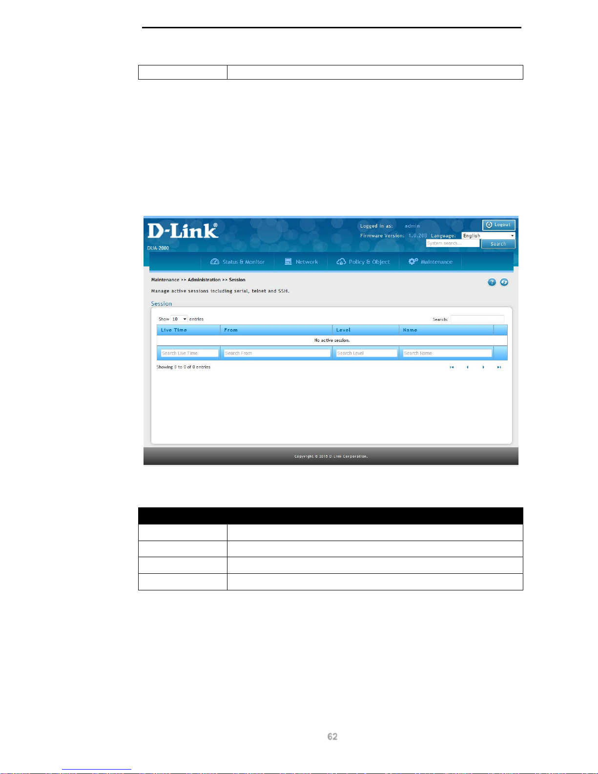
D-Link DUA-2000 Policy Manager User Manual
62
Disabled. Do not follow DST.
Table 10-5 – Date and Time
Click Save to save the changes made.
Click Cancel to revert the settings to their previous state.
Session
View the session information, showing all accounts logged-in to the system.
To get to the following page, browse to: Maintenance >> Administration >> Session:
Figure 10-6 – Session
The following fields are available:
Field Description
Live Time
How long the session has been active for.
From
The source device IP address.
Level
The permission level of the account.
Name
The name of the user logged-in.
Table 10-6 – Session
Click Next to view the next page.
Click Previous to view the previous page.
Page 68
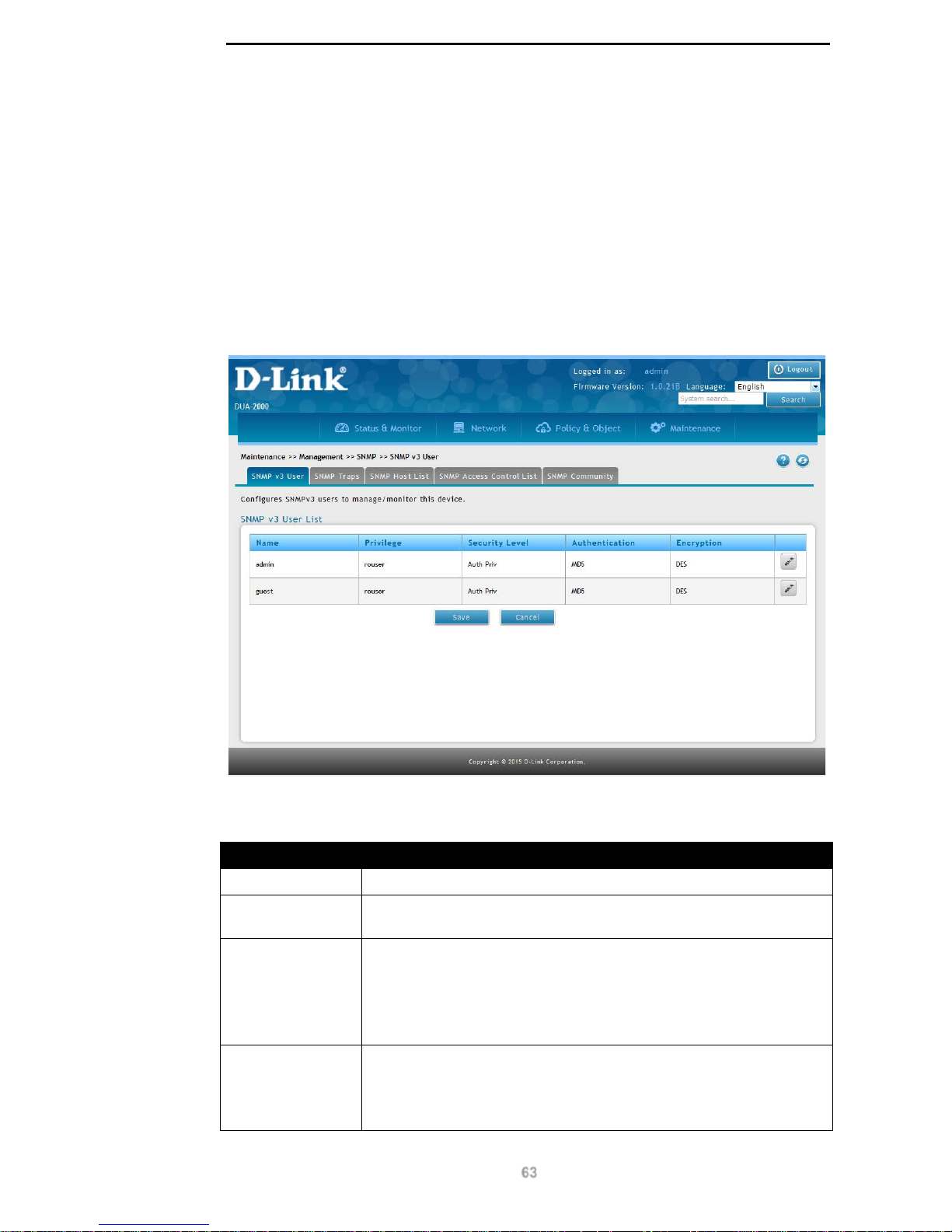
D-Link DUA-2000 Policy Manager User Manual
63
Management
SNMP
SNMP v3 User
Simple Network Management Protocol (SNMP) v3 is a protocol for administering devices on
an IP network. Management applications can be used to set and view system properties on
devices which support SNMP.
To get to the following page, browse to: Maintenance >> Management >> SNMP:
Figure 10-7 – SNMP v3 User
The following fields are available:
Field Description
Name
The name of the SNMP user account. This is either ‘admin’ or ‘guest’.
Privilege
The access level of the user. This cannot be changed and is set to
read-only (rouser).
Security Level
The security level of the user account. This dictates the security
requirements of the SNMP account access. It can be set to:
No-Auth: no authentication and no privacy.
Auth No-Priv: authentication and no privacy.
Auth Priv: authentication and privacy.
Authentication
The authentication function used to authenticate the SNMP data. This
can be set to:
MD5
SHA
Page 69
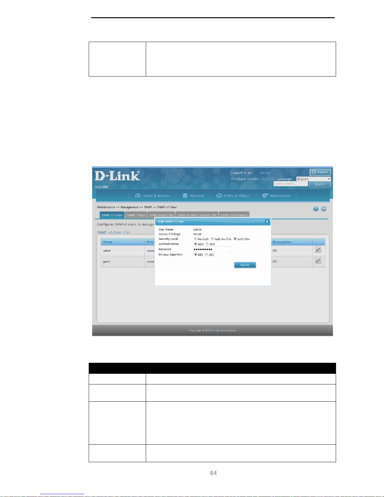
D-Link DUA-2000 Policy Manager User Manual
64
Encryption
The encryption algorithm used to ensure privacy of the SNMP data. It
can be set to:
DES
AES
Table 10-7 – SNMP v3 User
Click Edit to edit existing SNMP user settings.
Click Save to save the changes made.
Click Cancel to revert the settings to their previous state.
Edit SNMP V3 User
Click the Add or Edit buttons to view the following window:
Figure 10-8 – Edit SNMP V3 User
The following fields can be configured:
Field Description
User Name
The name of the SNMP user account. This is either ‘admin’ or ‘guest’.
Access Privilege
The access level of the user. This cannot be changed and is set to
read-only (rouser).
Security Level
The security level of the user account. This dictates the security
requirements of the SNMP account access. It can be set to:
No-Auth: no authentication and no privacy.
Auth No-Priv: authentication and no privacy.
Auth Priv: authentication and privacy.
Authentication
The authentication function used to authenticate the SNMP data. This
can be set to:
Page 70
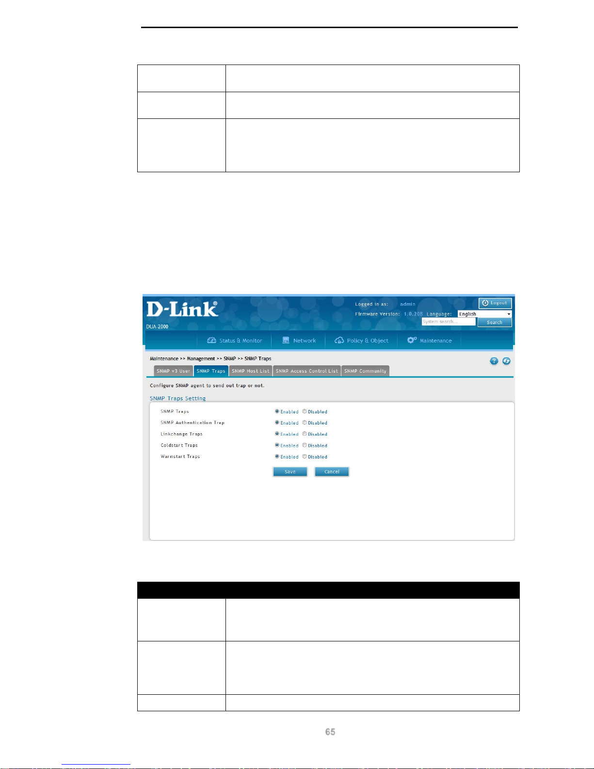
D-Link DUA-2000 Policy Manager User Manual
65
MD5
SHA
Password The password of the user, if No-Auth or Auth No-Priv have been
selected in the Security Level.
Privacy Algorithm
The encryption algorithm used to ensure privacy of the SNMP data. It
can be set to:
DES
AES
Table 10-8 – Edit SNMP V3 User
Click Apply to apply the settings.
SNMP Traps
This is used to enable and disable SNMP traps on the Policy Manager .
To get to the following page, browse to: Maintenance >> Management >> SNMP and click
on the SNMP Traps tab:
Figure 10-9 – SNMP Traps
The following fields are available:
Field Description
SNMP Traps
This is used to enable or disable SNMP traps and can be set to:
Enabled
Disabled
SNMP
Authentication
Trap
This is used to enable or disable SNMP Authentication Traps and can
be set to:
Enabled
Disabled
Linkchange Traps
This is used to enable or disable SNMP Linkchange Traps. These are
Page 71
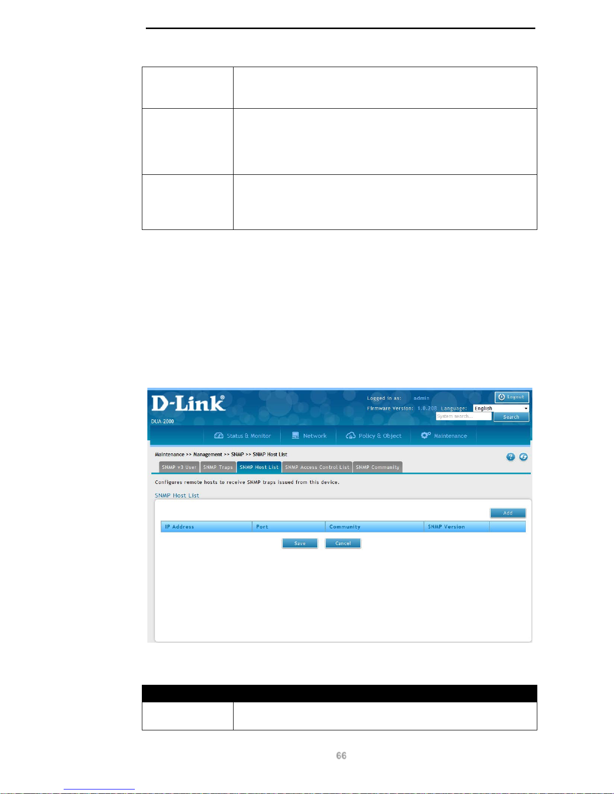
D-Link DUA-2000 Policy Manager User Manual
66
used if a link changes state and can be set to:
Enabled
Disabled
Coldstart Traps
This is used to enable or disable SNMP Coldstart traps. These are
used if the system was powered-off before being powered-on and can
be set to:
Enabled
Disabled
Warmstart Traps
This is used to enable or disable SNMP Warmstart traps. These are
used if the system was rebooted and can be set to:
Enabled
Disabled
Table 10-9 – SNMP Traps
Click Save to save the changes made.
Click Cancel to revert the settings to their previous state.
SNMP Host List
This is used to define Network Management Systems (NMSs) that will receive SNMP traps
from the Policy Manager.
To get to the following page, browse to: Maintenance >> Management >> SNMP and click
on the SNMP Host List tab:
Figure 10-10 – SNMP Host List
The following fields are available:
Field Description
IP Address
The IP address of the SNMP host receiving the traps from the Policy
Manager.
Page 72
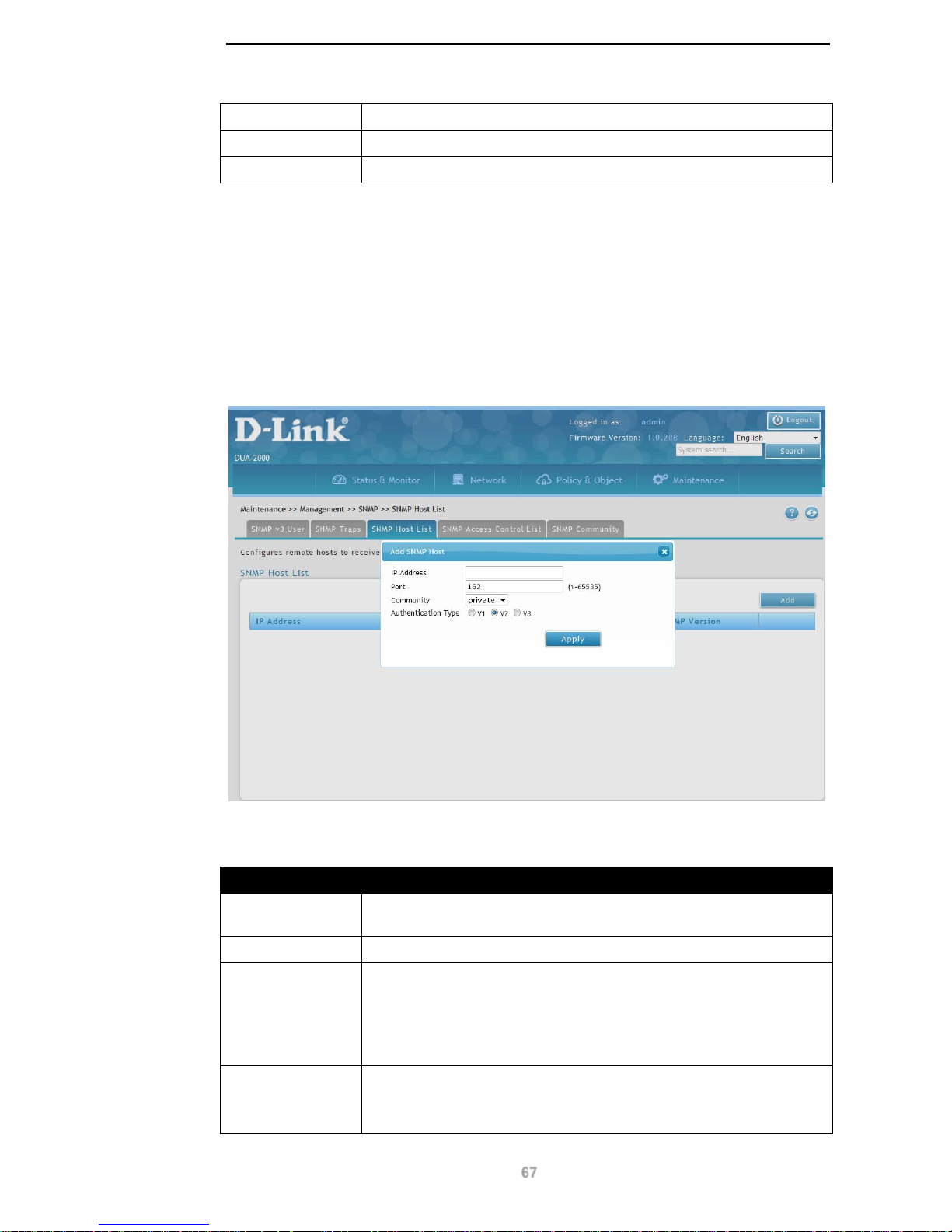
D-Link DUA-2000 Policy Manager User Manual
67
Port
The TCP port to use for SNMP traps.
Community
The community string to us e for SNMP traps.
SNMP Version
The SNMP protocol version to use for SNMP traps.
Table 10-10 – SNMP Host List
Click Add to add a SN M P Ho st .
Click Save to save the changes made.
Click Cancel to revert the settings to their previous state.
Add SNMP Host
Click the Add or Edit buttons to view the following window:
Figure 10-11 – Add SNMP Host
The following fields can be configured:
Field Description
IP Address
The IP address of the SNMP host receiving the traps from the Policy
Manager.
Port
The TCP port to use for SNMP traps. Default: 162, range: 1 – 65535.
Community
The community string to use for SNMP traps.
If the Authentication Type is set to V1 or V2, this is taken from the
SNMP Community Table Setting on the SNMP Community page.
If the Authentication Type is set to V3, this is taken from the SNMP v3
User List on the SNMP v3 User page.
Authentication
Type
The SNMP version to use for authentication. This can be set to:
V1
V2
Page 73
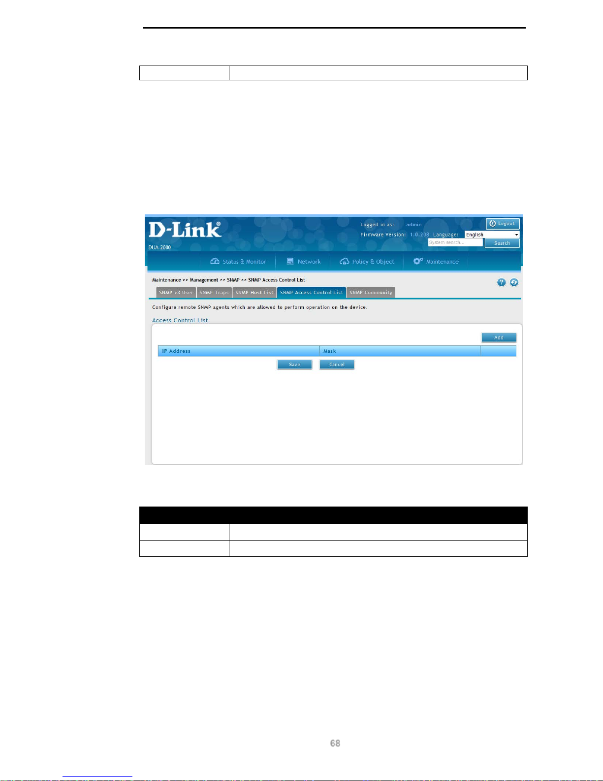
D-Link DUA-2000 Policy Manager User Manual
68
V3
Table 10-11 – Add SNMP Host
Click Apply to apply the settings.
Access Control List
This is a way to control which devices on the network have SNMP access to the Policy
Manager.
To get to the following page, browse to: Maintenance >> Management >> SNMP and click
on the Access Control List tab:
Figure 10-12 – Access Control List
The following fields are available:
Field Description
IP Address
The IP address of the network host.
Mask
The netmask of the network host.
Table 10-12 – Access Control List
Click Add to add an Access Control List.
Click Edit to edit existing Access Control List settings.
Click Delete to delete an Access Control List.
Click Save to save the changes made.
Click Cancel to revert the settings to their previous state.
Add Access Control List
Page 74
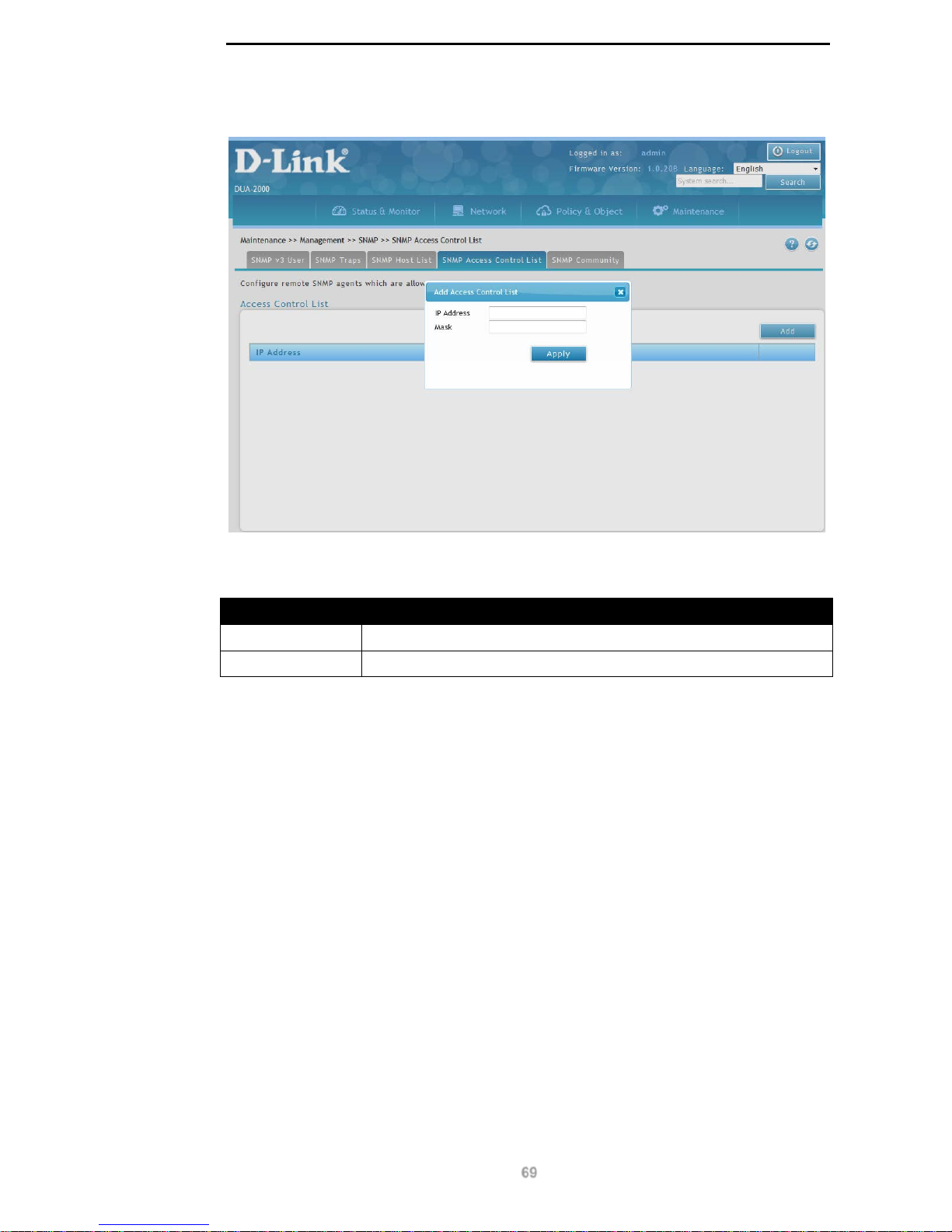
D-Link DUA-2000 Policy Manager User Manual
69
Click the Add or Edit buttons to view the following window:
Figure 10-13 – Add Access Control List
The following fields can be configured:
Field Description
IP Address
The IP address of the network host.
Mask
The netmask of the network host.
Table 10-13 – Add Access Control List
Click Apply to apply the settings.
SNMP Community
The SNMP community strings are a way of authenticating client devices. They can be used
to enable read-only or read-write access to the Policy Manager.
To get to the following page, browse to: Maintenance >> Management >> SNMP and click
on the SNMP Community tab:
Page 75
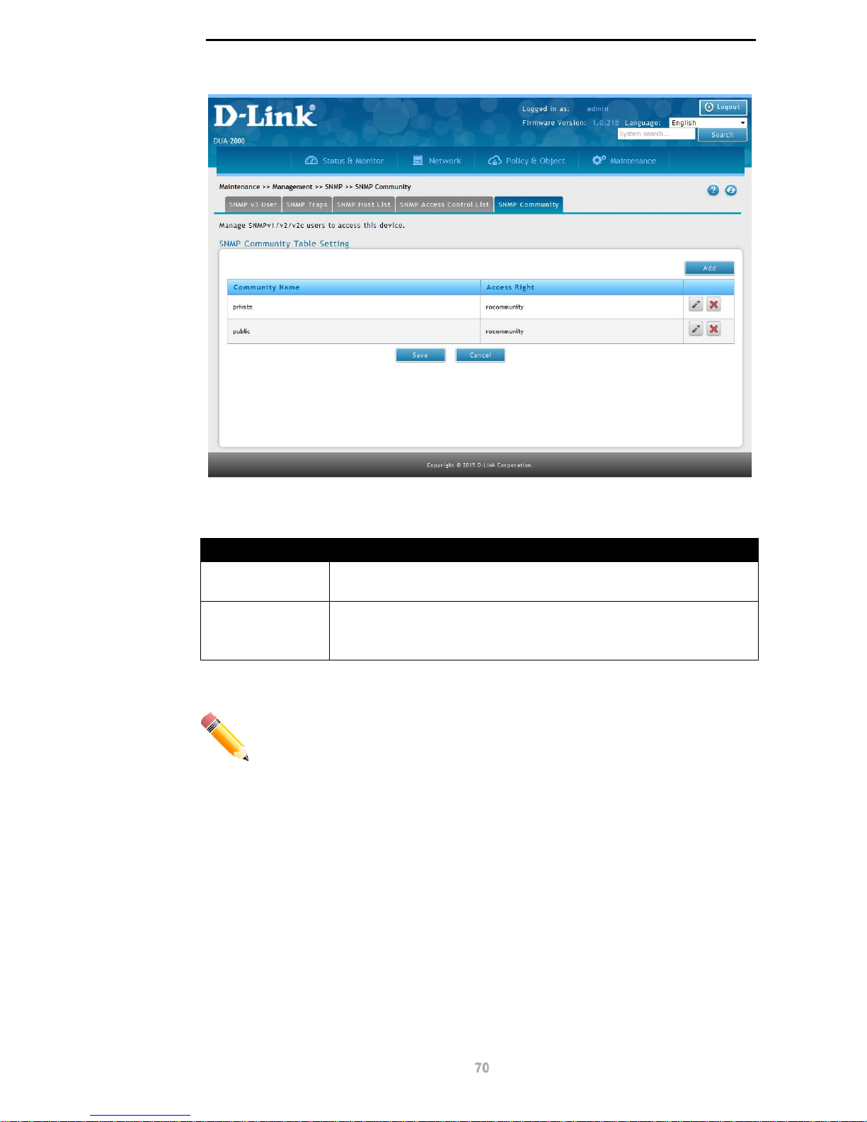
D-Link DUA-2000 Policy Manager User Manual
70
Figure 10-14 – SNMP Community
The following fields are available:
Field Description
Community Name
The SNMP community string. This is used to authenticate client
devices connecting to the Policy Manager us ing SNMP.
Access Right
The access rights of the community string. This can only be read-only.
It can be set to:
rocommunity
Table 10-14 – SNMP Community
NOTE: It is recommended that the default SNMP community strings are changed
on the Policy Manager.
Click Add to add an SNMP Community.
Click Edit to edit existing SNMP Community settings.
Click Delete to delete an SNMP Comm unity.
Click Save to save the changes made.
Click Cancel to revert the settings to their previous state.
Add SNMP Community
Click the Add or Edit buttons to view the following window:
Page 76
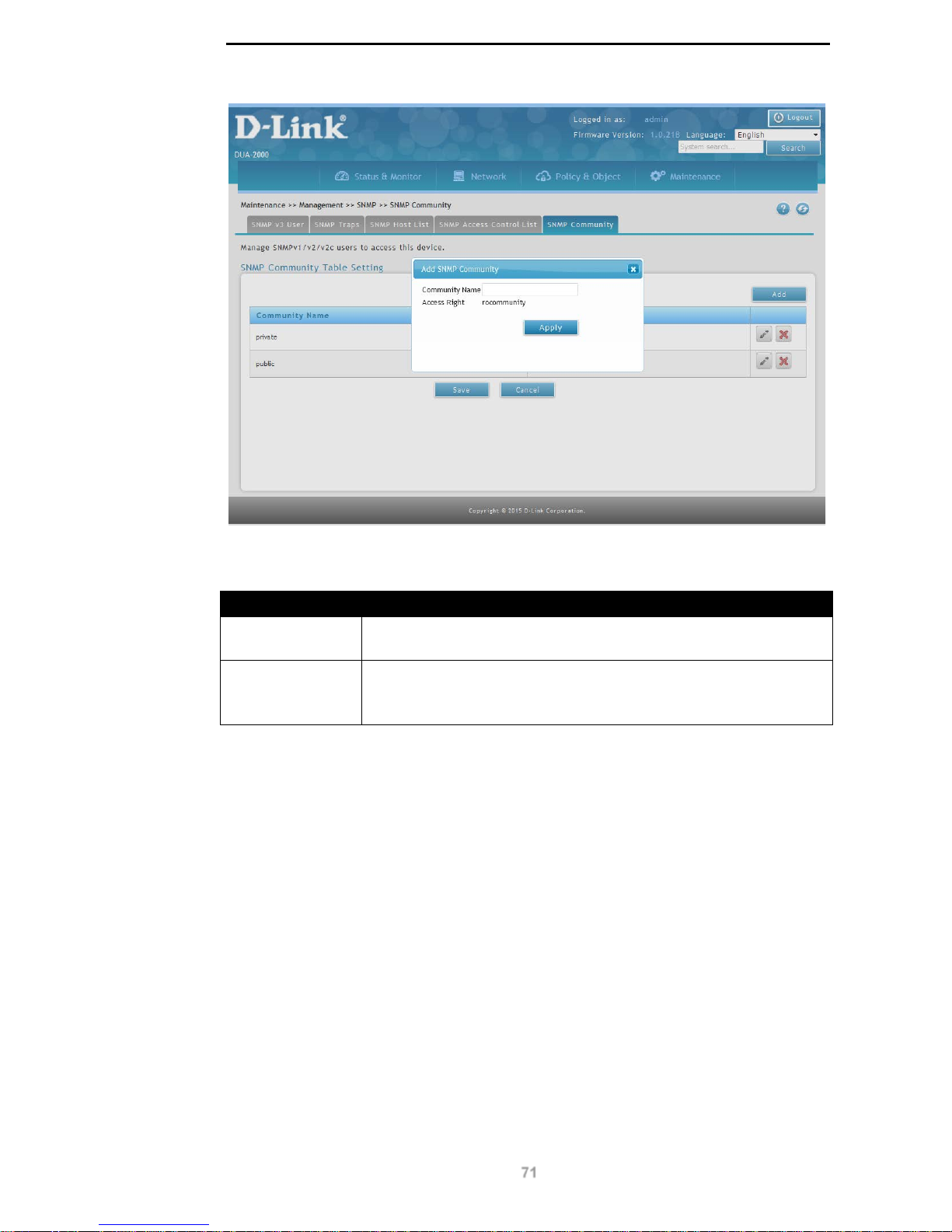
D-Link DUA-2000 Policy Manager User Manual
71
Figure 10-15 – Add SNMP Community
The following fields can be configured:
Field Description
Community Name
The SNMP community string. This is used to authenticate client
devices connecting to the Policy Manager us ing SNMP.
Access Right
The access rights of the community string. This can only be read-only.
It can be set to:
rocommunity
Table 10-15 – Add SNMP Community
Click Apply to apply the settings.
Telnet / SSH
Telnet and Secure Shell (SSH) are protocols for remote management of IP devices.
To get to the following page, browse to: Maintenance >> Management >> Telnet / SSH:
Page 77
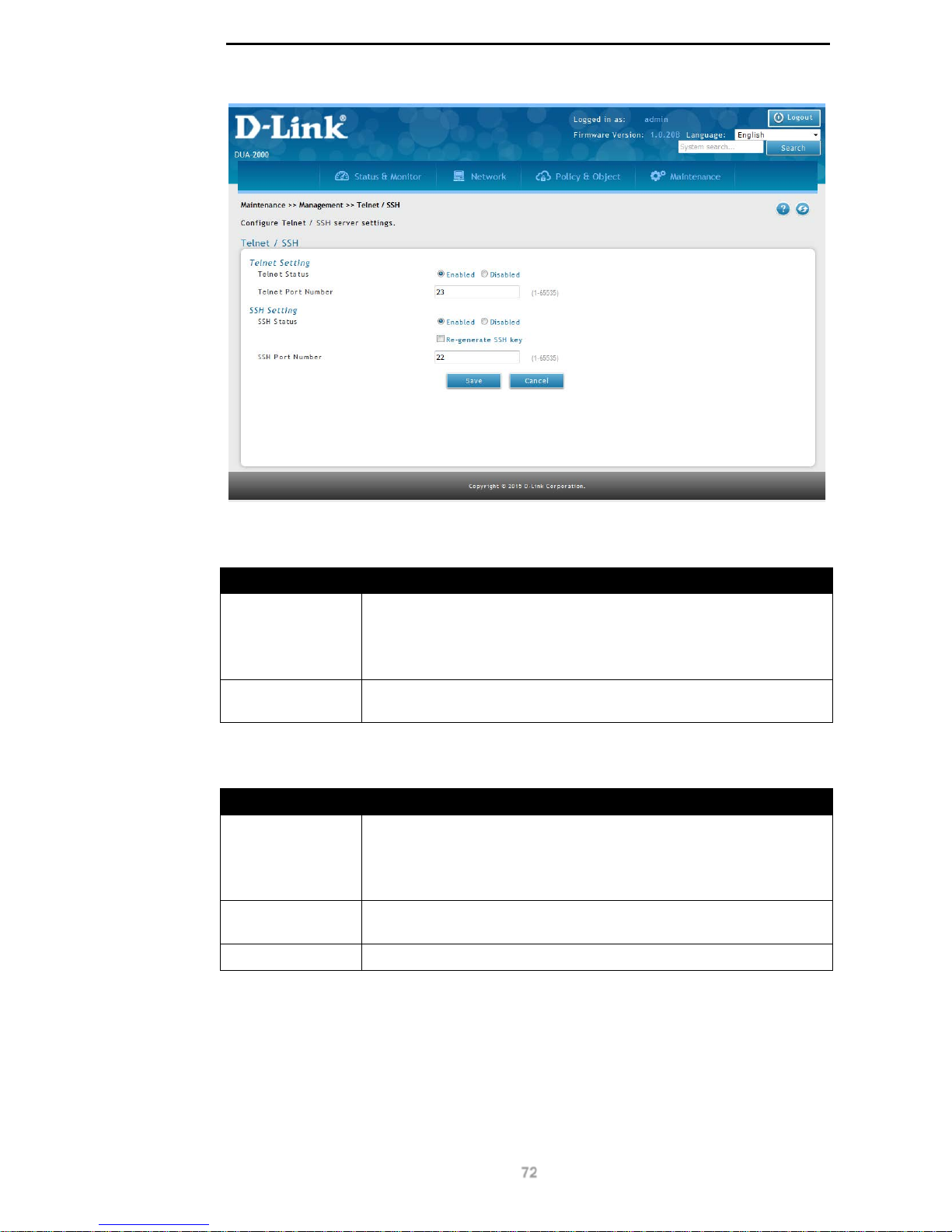
D-Link DUA-2000 Policy Manager User Manual
72
Figure 10-16 – Telnet / SSH
The following fields are available in the Telnet Setting section:
Field Description
Telnet Status
The status of the Telnet server on the Polic y Manager . This can be set
to:
Enabled
Disabled
Telnet Port
Number
The Telnet port number. Default: 23, range: 1 - 65535.
Table 10-16 – Telnet Setting
The following fields are available in the SSH Setting section:
Field Description
SSH Status
The status of the SSH server on the Polic y Manag er . This can be set
to:
Enabled
Disabled
Re-generate SSH
key
This is used to re-generate the private SSH key used by the Policy
Manager.
SSH Port Number
The SSH port number. Default: 22, range: 1 - 65535.
Table 10-17 – SSH Setting
Click Save to save the changes made.
Click Cancel to revert the settings to their previous state.
Page 78
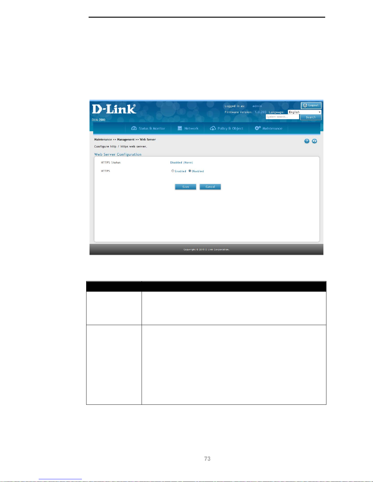
D-Link DUA-2000 Policy Manager User Manual
73
Web Server Configuration
This is used to enable or disable HTTPS on the Policy Manager Web UI. It allows a selfsigned certificated to be generated, or for a signed certificate to be imported. This allows
connections to the Policy Manager Web UI to be encrypted or sent in plain text.
To get to the following page, browse to: Maintenance >> Management >> Web Server:
Figure 10-17 – Web Server Configuration
The following fields are available:
Field Description
HTTPS
The status of the HTTPS server on the Policy Manager. The default is
Disabled. This can be set to:
Enabled
Disabled
Certificate This field appears if the HTTPS status is set to Enabled. The
following fields are available:
Select self-signed certificate to use a self-signed SS L/TLS
certificate. Select Re-generate self-signed key to re-
generate the self-signed key used to sign SSL/TLS
certificates us ed b y the Policy Manager.
Select imported certificate and click Import to import a
signed SSL/TLS certificate. This can be entered into the
Import Certificate box which is presented. Press Apply to
save the settings. Certificates in the PEM format are
accepted.
Table 10-18 – Web Server Configuration
Click Save to save the changes made.
Page 79
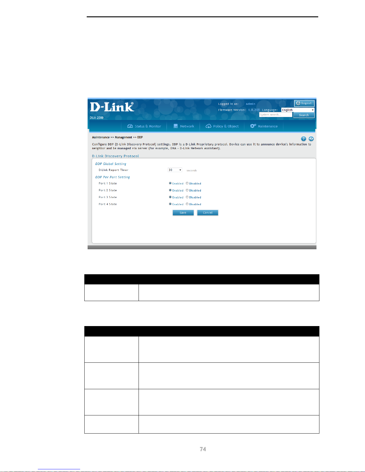
D-Link DUA-2000 Policy Manager User Manual
74
DDP
D-Link Discovery Protocol (DDP) is a protocol for automatic discovery of IP devices. It can
be used to identify network devices to each other and manage the network using software
such as D-Link Network Assistant (DNA).
To get to the following page, browse to: Maintenance >> Management >> DDP:
Figure 10-18 – D-Link Discovery Protocol
The following fields are available in the DDP Global Setting section:
Field Description
D-Link Report
Timer
The amount of time to wait between scans of the directly connected
local devices.
Table 10-19 – DDP Global Setting
The following fields are available in the DDP Per Port Setting section:
Field Description
Port 1 State
Enable of disable DNA on port 1. This can be set to:
Enabled
Disabled
Port 2 State
Enable of disable DNA on port 2. This can be set to:
Enabled
Disabled
Port 3 State
Enable of disable DNA on port 3. This can be set to:
Enabled
Disabled
Port 4 State
Enable of disable DNA on port 4. This can be set to:
Enabled
Page 80
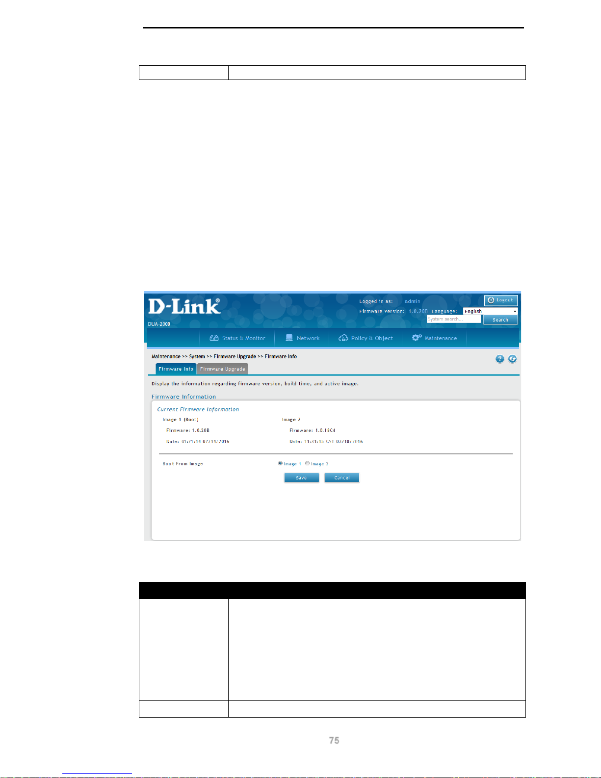
D-Link DUA-2000 Policy Manager User Manual
75
Disabled
Table 10-20 – DDP Per Port Setting
Click Save to save the changes made.
Click Cancel to revert the settings to their previous state.
System
Firmware Upgrade
Firmware Info
This page lists the firmware information, including the image firmware, upload date and time
and the active image.
To get to the following page, browse to: Maintenance >> System >> Firmware Upgrade:
Figure 10-19 – Firmware Info
The following fields are available in the Current Firmware Information section:
Field Description
Image1 (Boot)
This is the firmware image for Image 1. If this has been set as the
default image to boot from, the word (Boot) will be displayed next to
the image name.
The image properties are as follows:
Firmware: The firmware version.
Date: The date that the image was uploaded to the Policy Manager, in
HH:MM:SS MM/DD/YYYY format.
Image2
This is the firmware image for Image 2. If this has been set as the
Page 81
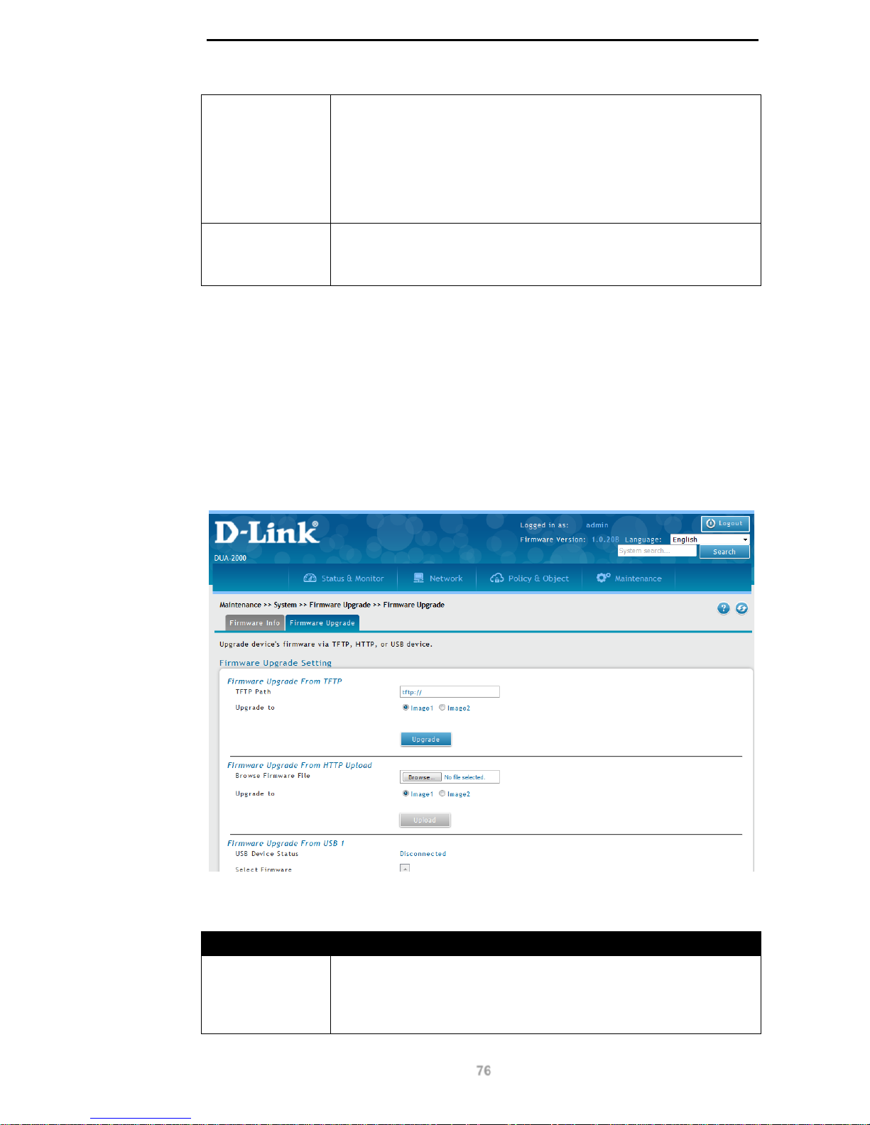
D-Link DUA-2000 Policy Manager User Manual
76
default image to boot from, the word (Boot) will be displayed next to
the image name.
The image properties are as follows:
Firmware: The firmware version.
Date: The date that the image was uploaded to the Policy Manager, in
HH:MM:SS MM/DD/YYYY format.
Boot From Image
Select the image to boot from. This can be set to:
Image1
Image2
Table 10-21 – Current Firmware Information
Click Save to save the changes made.
Click Cancel to revert the settings to their previous state.
Firmware Upgrade
This page can be used to upgrade the Polic y Manager’s firmware, using TFTP, HTTP and
USB devices.
To get to the following page, browse to: Maintenance >> System >> Firmware Upgrade
and click on the Firmware Upgrade tab:
Figure 10-20 – Firmware Upgrade
The following fields are available in the Firmware Upgrade From TFTP section:
Field Description
TFTP Path
The path to the firmware image file. This is transferred via TFTP and
is in the format:
tftp://<host><path to image>
<host> can be an IP address or DNS name
Page 82

D-Link DUA-2000 Policy Manager User Manual
77
<path to image> can be the name of the image file or a path to the
image file on the TFTP server.
Upgrade to
The image to upgrade. This can be set to:
Image1
Image2
Table 10-22 – Firmware Upgrade From TFTP
Click Upgrade to upgrade the firmware.
The following fields are available in the Firmware Upgrade From HTTP Upload section:
Field Description
Browse Firmware
File
The path to the firmware image file. This is transferred via HTTP and
is in the format:
tftp://<host><path to image>
<host> can be an IP address or DNS name
<path to image> can be the name of the image file or a path to the
image file on the HTTP server.
Upgrade to
The image to upgrade. This can be set to:
Image1
Image2
Table 10-23 – Firmware Upgrade From HTTP Upload
Click Upload to upgrade the firmware.
The following fields are available in the Firmware Upgrade From USB 1 section:
Field Description
USB Device
Status
The USB device status of USB port 1. This can be:
Connected
Disconnected
Select Firmware
The folder on the USB drive where the backup files are located.
Upload to
The image to upgrade. This can be set to:
Image1
Image2
Table 10-24 – Firmware Upgrade From USB 1
Click Upgrade to upgrade the firmware.
The following fields are available in the Firmware Upgrade From USB 2 section:
Field Description
USB Device
Status
The USB device status of USB port 1. This can be:
Connected
Disconnected
Select Firmware
The folder on the USB drive where the backup files are located.
Upload to
The image to upgrade. This can be set to:
Image1
Image2
Table 10-25 – Firmware Upgrade From USB 2
Page 83
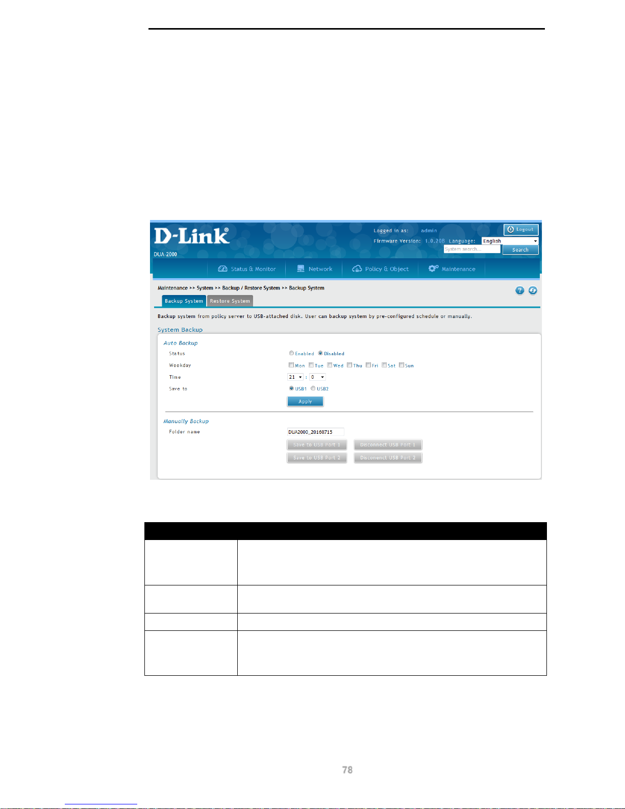
D-Link DUA-2000 Policy Manager User Manual
78
Click Upgrade to upgrade the firmware.
Backup / Restore System
Backup System
This page can be used to back up the system configuration, either manually or using an
automated backup.
To get to the following page, browse to: Maintenance >> Management >> Backup /
Restore System:
Figure 10-21 – Backup System
The following fields are available in the Auto Backup section:
Field Description
Status
The status of the backup schedule. This can be:
Enabled
Disabled
Weekday
The day of the week the backup takes place on. This can be any day
from Mon – Sun.
Time
The time that the backup takes place at. This is in 24 h format.
Save to
The USB port to save the system configuration to. This can be:
USB1
USB2
Table 10-26 – Auto Backup
Click Apply to apply the settings.
The following fields are available in the Manually Backup section:
Page 84
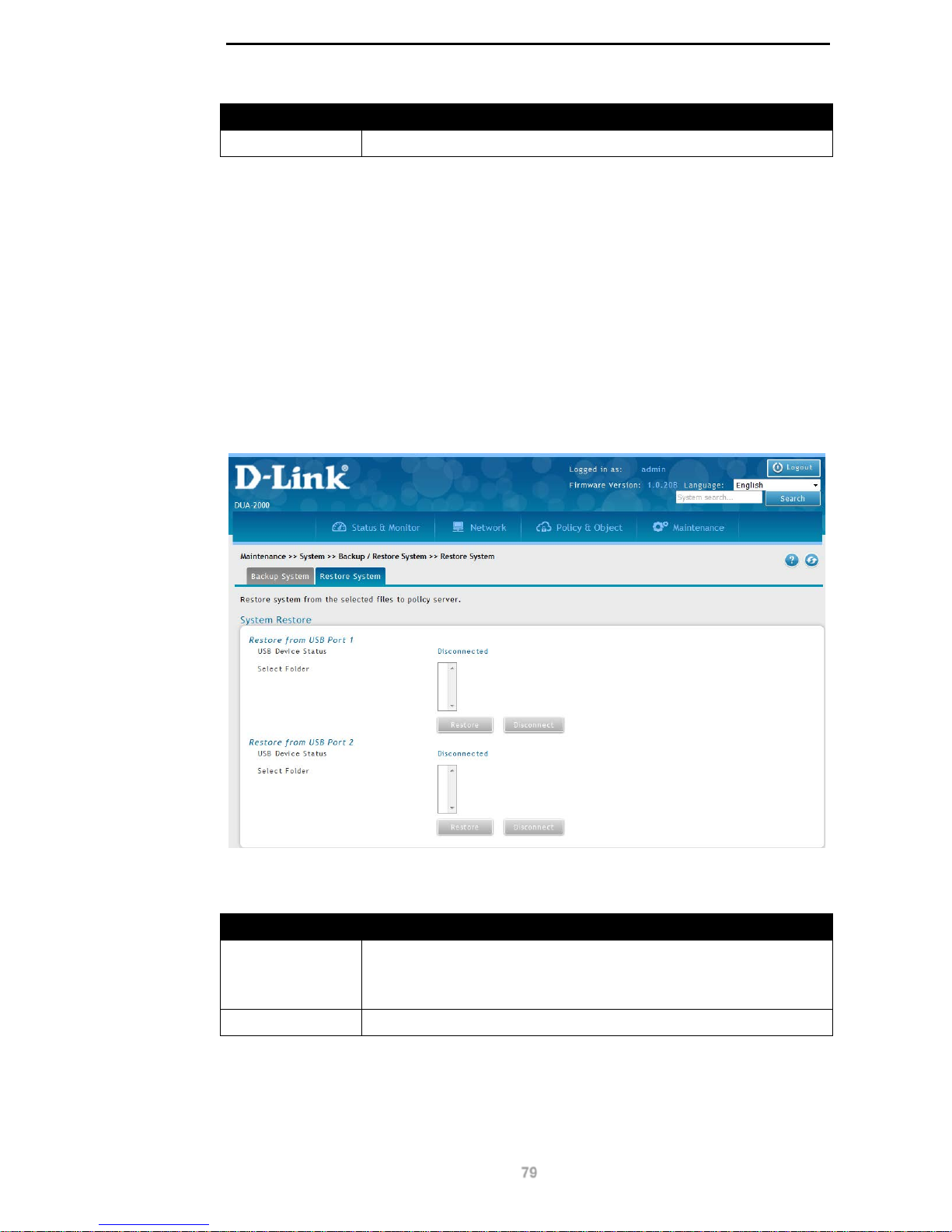
D-Link DUA-2000 Policy Manager User Manual
79
Field Description
Folder name
The folder on the USB device to save the backup file to.
Table 10-27 – Manually Backup
Click Save to USB Port 1 to save the configuration to USB port 1.
Click Disconnect USB Port 1 to un-mount the USB device in USB port 1.
Click Save to USB Port 2 to save the configuration to USB port 2.
Click Disconnect USB Port 2 to un-mount the USB device in USB port 2.
Restore System
This page can be used to restore the system configuration from a previous back up.
To get to the following page, browse to: Maintenance >> Management >> Backup /
Restore System and click on the Restore System tab:
Figure 10-22 – Restore System
The following fields are available in the Restore from USB Port 1 section:
Field Description
USB Device
Status
The USB device status of USB port 1. This can be:
Connected
Disconnected
Select Folder
The folder on the USB drive where the backup files are located.
Table 10-28 – Restore from USB Port 1
Click Restore to restore the system configuration from the backup.
The following fields are available in the Restore from USB Port 2 section:
Page 85
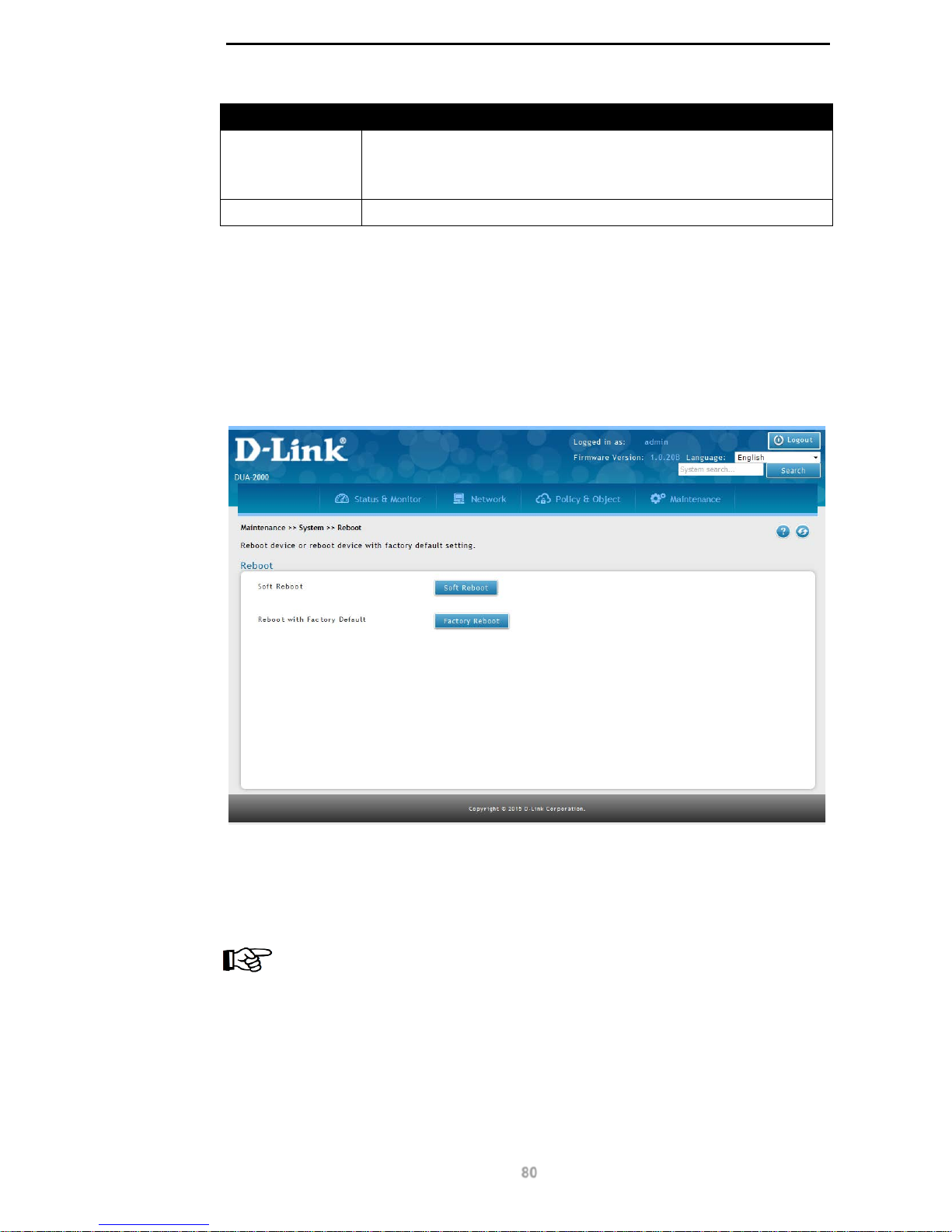
D-Link DUA-2000 Policy Manager User Manual
80
Field Description
USB Device
Status
The USB device status of USB port 2. This can be:
Connected
Disconnected
Select Folder
The folder on the USB drive where the backup files are located.
Table 10-29 – Restore from USB Port 2
Click Restore to restore the system configuration from the backup.
Reboot
Use this page to reboot the Policy Manager. This can be done with both the existing
configuration settings and restoring the settings to their factory defaults.
To get to the following page, browse to: Maintenance >> System >> Reboot:
Figure 10-23 – Reboot
Click Soft Reboot to reboot the Policy Manager, keeping the current configuration.
Click Factory Reboot to reboot the Policy Manager, restoring the factory default
configuration.
NOTICE: Clicking Fac tory Reboot will restore the Policy Manager to the factory
default configuration. This will lose any configuration settings and the device will
be unreachable for about 150 seconds.
HA
High Availability (HA) is configured on this page. This consists of two Policy Manager s in an
HA pair, with one Active an d one Sta ndby. If the heartbeat signa l is los t bet w een the de v ices ,
then they both become Active.
Page 86
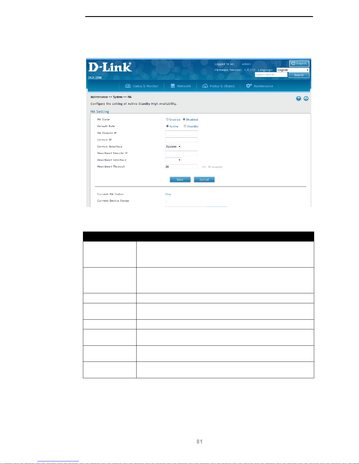
D-Link DUA-2000 Policy Manager User Manual
81
To get to the following page, browse to: Maintenance >> System >> HA:
Figure 10-24 – HA
The following fields are available:
Field Description
HA State
The global HA status. This can be set to:
Enabled
Disabled
Default Role
The Policy Manager’s default role in the HA pair. This can be set to:
Active
Standby
HA Remote IP
The IP address of the alternate Policy Manager in the HA pair.
Service IP
The virtual IP address that responds to client requests. This is
allocated to whichever Policy Manager is the Active server in the pair.
Service Interface
The interface that is used to respond to clients.
Heartbeat Remote
IP
The remote IP to poll for heartbeat signals. If this fails then the current
server is assumed to be the Active one and assumes the Active role.
Heartbeat
Interface
The interface used for heartbeat signals.
Heartbeat
Timeout
This is the time to wait before changing the role of the Policy Manager
to Active. The default is 20 seconds. This range is: 15 – 90 seconds.
Table 10-30 – HA
Click Save to save the changes made.
Click Cancel to revert the settings to their previous state.
The following fields are available:
Page 87
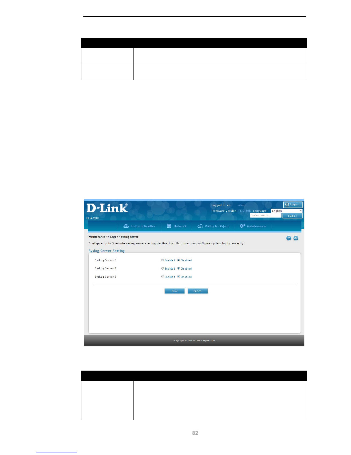
D-Link DUA-2000 Policy Manager User Manual
82
Field Description
Current HA
Status
The current HA status.
Current Device
Status
The current device status in the HA pair.
Table 10-31 – HA
Click To Activate to make the current Policy Manager the Active server in the HA pair.
Click Stop to stop the HA service on the Policy Manager.
Click Start to start the HA service on the Policy Manage r.
Logs
Syslog Server
This page can be used to configure Syslog servers and the severity of the logs per server.
Up to 3 Syslog servers can be defined.
To get to the following page, browse to: Maintenance >> Logs >> Syslog Server:
Figure 10-25 – Syslog Server
The following fields are available:
Field Description
SysLog Server 1
The status of SysLog Server 1. This can be set to:
Disabled. Disable Syslog logging.
Enabled. Enable Sys lo g loggi ng. The following fields are available:
FQDN / IP Address. The DNS name or IP address of the
Page 88
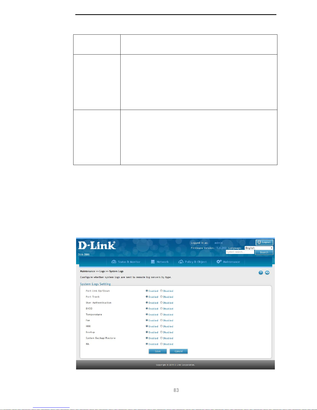
D-Link DUA-2000 Policy Manager User Manual
83
Syslog server.
Severity. The severity of the logging sent to the Syslog
server.
SysLog Server 2
The status of SysLog Server 2. This can be set to:
Disabled. Disable Syslog logging.
Enabled. Enable Syslog logging. The following fields are available:
FQDN / IP Address. The DNS name or IP address of the
Syslog server.
Severity. The severity of the logging sent to the Syslog
server.
SysLog Server 3
The status of SysLog Server 3. This can be set to:
Disabled. Disable Syslog logging.
Enabled. Enable Syslog logging. The following fields are available:
FQDN / IP Address. The DNS name or IP address of the
Syslog server.
Severity. The severity of the logging sent to the Syslog
server.
Table 10-32 – Syslog Server
Click Save to save the changes made.
Click Cancel to revert the settings to their previous state.
System Logs
The page is used to configure the system logs sent to remote logging servers.
To get to the following page, browse to: Maintenance >> Logs >> System Logs:
Figure 10-26 – System Logs
Page 89
D-Link DUA-2000 Policy Manager User Manual
84
The following fields are available:
Field Description
Port Link
Up/Down
Enable or disable Port Link Up/Down logs. This can be set to:
Enabled
Disabled
Port Trunk
Enable or disable Port Trunk logs. This can be set to:
Enabled
Disabled
User
Authentication
Enable or disable User Aut hent ic ati on logs. This can be set to:
Enabled
Disabled
BYOD
Enable or disable BYOD logs. This can be set to:
Enabled
Disabled
Temperature
Enable or disable Temperature logs. This can be set to:
Enabled
Disabled
Fan
Enable or disable Fan logs. This can be set to:
Enabled
Disabled
HDD
Enable or disable HDD logs. This can be set to:
Enabled
Disabled
Bootup
Enable or disable Bootup logs. This can be set to:
Enabled
Disabled
System
Backup/Restore
Enable or disable System Backup/Restore logs. This can be set to:
Enabled
Disabled
HA
Enable or disable HA logs. This can be set to:
Enabled
Disabled
Table 10-33 – System Logs
Click Save to save the changes made.
Click Cancel to revert the settings to their previous state.
Alert
Email Alert
This page is used to configure email alerts for the system.
To get to the following page, browse to: Maintenance >> Logs >> Alert:
Page 90
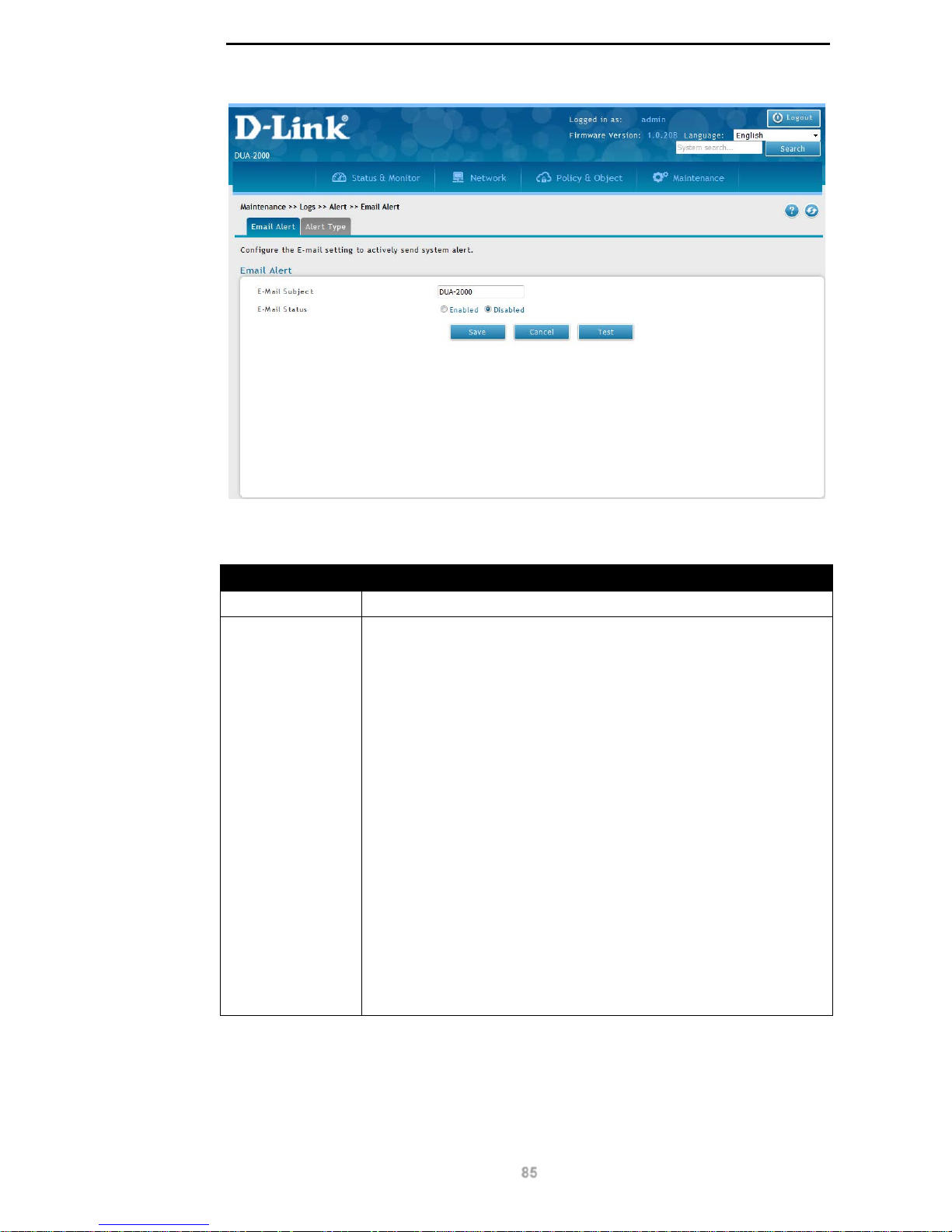
D-Link DUA-2000 Policy Manager User Manual
85
Figure 10-27 – Email Alert
The following fields are available:
Field Description
E-Mail Subject
The subject of the email that will be sent from the Policy Manager.
E-Mail Status
The status of the email alert. This can be set to:
Disabled. Disable system alert emails.
Enabled. Enable system alert emails. The following fields are
available:
E-Mail Server Address. The address to send the email from.
SMTP Port. The SMTP port on the SMTP server. Default: 25,
range: 1 – 65535.
Use TLS. Use TLS for SMTP communication. This can be set
to Enabled or Disabled.
Use STARTTLS Use STARTTLS for SMTP communication.
This can be set to Enabled or Disabled.
Return E-Mail Address. The return email address of the
email.
Send to E-Mail Address (1). Recipient email address 1.
Send to E-Mail Address (2). Recipient email address 2.
Send to E-Mail Address (3). Recipient email address 3.
Authentication with SMTP. The authentication method to
use with SMTP. This can be set to: None, Plain Login or
CRAM-MD5.
Table 10-34 – Email Alert
Click Save to save the changes made.
Click Cancel to revert the settings to their previous state.
Page 91
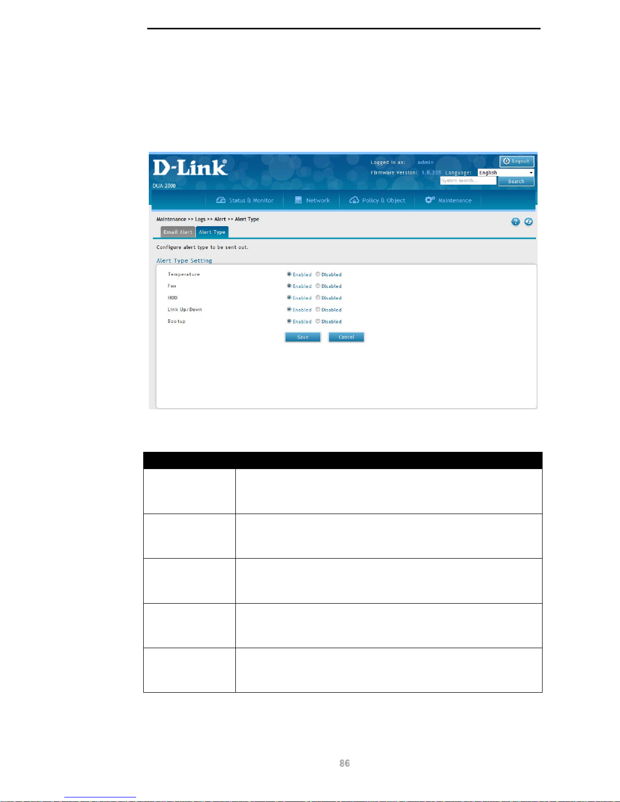
D-Link DUA-2000 Policy Manager User Manual
86
Alert Type
This page is used to configure the alert type to be included in the email alerts.
To get to the following page, browse to: Maintenance >> Logs >> Alert and click on the
Alert Type tab:
Figure 10-28 – Alert Type
The following fields are available:
Field Description
Temperature
Enable or disable Temperature alerts. This can be set to:
Enabled
Disabled
Fan
Enable or disable Fan alerts. This can be set to:
Enabled
Disabled
HDD
Enable or disable HDD alerts. This can be set to:
Enabled
Disabled
Link Up/Down
Enable or disable Link Up/Down alerts. This can be set to:
Enabled
Disabled
Bootup
Enable or disable Bootup alerts. This can be set to:
Enabled
Disabled
Table 10-35 – Alert Type
Click Save to save the changes made.
Click Cancel to revert the settings to their previous state.
Page 92
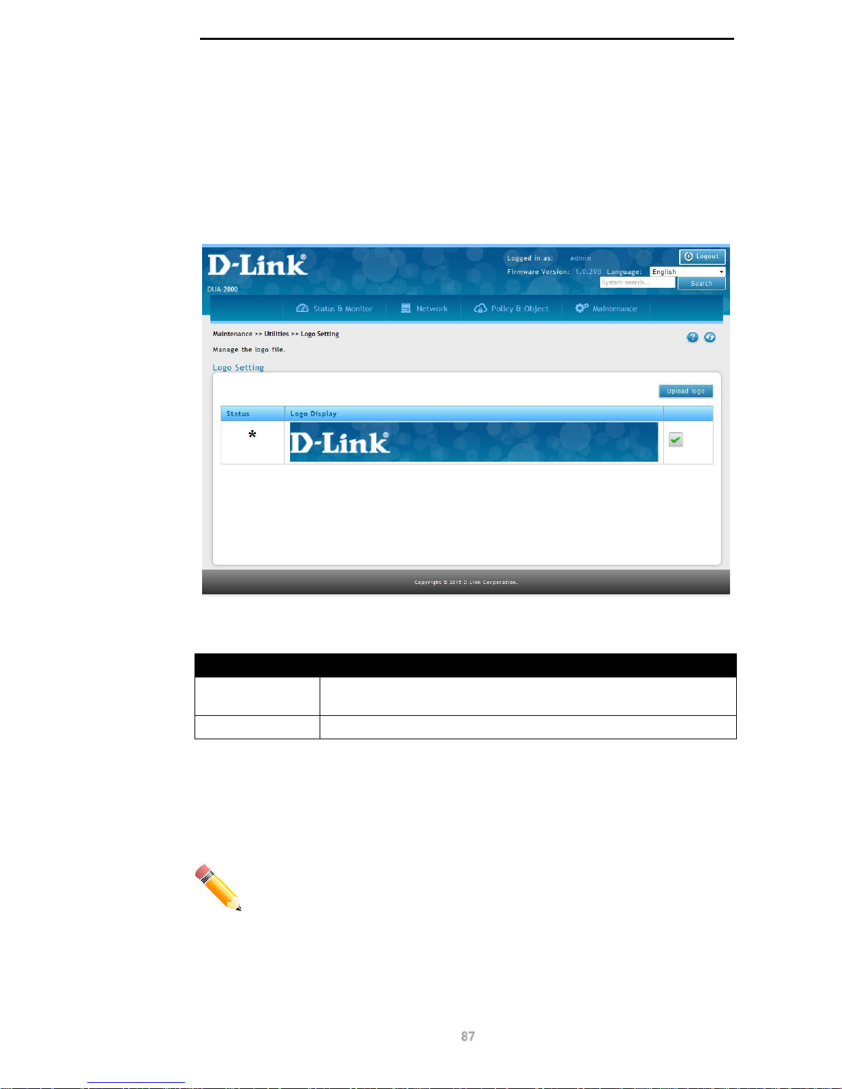
D-Link DUA-2000 Policy Manager User Manual
87
Utilities
Logo Setting
Use this page to set the banner at the top of the web interface.
To get to the following page, browse to: Maintenance >> Utilities >> Logo Setting:
Figure 10-29 – Logo Setting
The following fields are avail able:
Field Description
Status
The status of the image file. A ‘*’ will be shown next to the image in
use.
Logo Display
The image that has been uploaded.
Table 10-36 – Logo Setting
Click the green tick next to the image to use it as the logo at the top of the web page.
Click the red cross next to the image to delete the image.
Click Upload logo to upload a new image file.
NOTE: It is recommend that the image size is less than 200 px x 80 px.
Click Save to save the changes made.
Click Cancel to revert the settings to their previous state.
Page 93
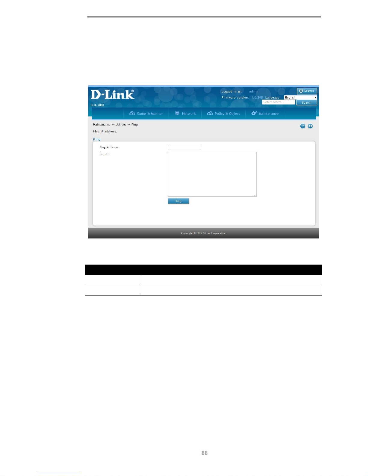
D-Link DUA-2000 Policy Manager User Manual
88
Ping
This page is used to perform ping tests.
To get to the following page, browse to: Maintenance >> Utilities>> Ping:
Figure 10-30 – Ping
The following fields are available:
Field Description
Ping Address
The IP address to ping.
Result
The results of the ping test.
Table 10-37 – Ping
Click Ping to perform the ping test.
Page 94

D-Link DUA-2000 Policy Manager User Manual
89
10. Appendix A - Technical
Specifications
Capacity
• New Session/Second:
o 100
• User Database:
o 10,000
Hardware
Specification
Processor and
System Memory
• Processor and System Memory
o Processor
MIPS based
1000MHz 64-bit
Multi-core
Processor
o Flash
eMMC NAND
Flash: 4GB
Nor-Flash: 2MB
o System Memory
2GB DDR3
I/O Interface
• External USB Port
o 2 USB 2.0 port (Type-A
Host)
• Serial port
o 1 RJ-45 connector
• Ethernet connector
o 4* 10/100/1000 Mbps
Gigabit Ethernet ports
o 4* 100/1000 Mbps SFP
combo ports
• Storage
o Hard drive: 256GB
• Power Supply
o Internal universal power
supply, 100-240VAC, 5060Hz
• Power Jack
o AC Power Jack with
ON/OFF switch.
Physical &
Environment
• Internal Power
o AC Input: 100-240 50/60Hz
• Operating Temperature
o 0 - 40°C
• Storage Temperature
o -20 - 70°C
• Humidity
o 5 - 95% non-condensing
• Acoustic
o Smart Fan Design
• Dimensions (L x W x H):
440 x 310 x 44 mm (17.32 x 12.20
x 1.73 inches)
Page 95

D-Link DUA-2000 Policy Manager User Manual
90
11. Appendix B – Rack Mount
Instructions
The following or similar rack-mount instructions are inc lud ed with the ins ta l lat ion ins truc tions :
A) Elevated Operating Ambient - If installed in a closed or multi-unit rack assembly, the operating
ambient temperature of the rack environment may be greater than room ambient. Therefore,
consideration should be given to installing the equipment in an environment compatible with the
maximum ambient temperature (Tma) specified by the manufacturer.
B) Reduced Air Flow - Installation of the equipment in a rack should be such that the amount of air
flow required for safe operation of the equipment is not compromised.
C) Mechanical Loading - Mounting of the equipment in the rack should be such that a hazardous
condition is not achieved due to uneven mechanical loading.
D) Circuit Overloading - Consideration should be given to the connection of the equipment to the
supply circuit and the effect that overloading of the circuits might have on overcurrent protection and
supply wiring. Appropriate consideration of equipment nameplate ratings should be used when
addressing this concern.
E) Reliable Earthing - Reliable earthing of rack-mounted equipment should be maintained. Particular
attention should be given to supply connections other than direct connections to the branch circuit
(e.g. use of power strips).
 Loading...