

Page 1
D-Link DSS-8+
8-port 10/100 Ethernet Switch
Manual
Rev. 12224
Building Networks for People
Ver.1.01
Page 2

TABLE OF CONTENTS
ABOUT THIS GUIDE................................................................ 1
PURPOSE................................................................................. 1
INTRODUCTION....................................................................... 2
FAST ETHERNET TECHNOLOGY................................................. 2
SWITCHING TECHNOLOGY......................................................... 2
FEATURES................................................................................ 4
UNPACKING AND SETUP....................................................... 6
UNPACKING.............................................................................. 6
SETUP...................................................................................... 6
IDENTIFYING EXTERNAL COMPONENTS ............................ 7
FRONT PANEL .......................................................................... 7
LED INDICATORS ..................................................................... 7
REAR PANEL ............................................................................ 8
CONNECTING THE SWITCH................................................... 9
COMPUTER TO DSS-8+......................................................... 9
HUB TO DSS-8+....................................................................... 9
DSS-8+ TO OTHER DEVICES ..................................................... 9
PORT SPEED & DUPLEX MODE ............................................... 10
MOUNTING THE SWITCH ON A WALL................................ 11
TECHNICAL SPECIFICATIONS ............................................ 12
RJ-45 PIN SPECIFICATION................................................... 14
WARRANTY..................................... ...................................... 15
TECHNICAL SUPPORT ......................................................... 20
ii
Page 3

ABOUT THIS GUIDE
Congratulations on your purchase of the DSS-8+ Switch. This
device integrates 100Mbps Fast Ethernet and 10Mbps Ethernet
network capabilities into one high-performance, easy-to-use
solution.
Purpose
This manual will familiarize you with the DSS-8+ Switch and guide
you through the installation process.
Conventions
For simplicity, this documentation uses the term “Switch” (first letter
upper case) to refer to the DSS-8+ Ethernet Switch, and “switch”
(first letter lower case) to refer to other Ethernet switches.
1
Page 4

INTRODUCTION
Fast Ethernet Technology
The growing importance of LANs and the increasing complexity of
desktop computing applications are fueling the need for high
performance networks. 100BASE-T (Fast Ethernet) provides a costeffective and high-performance solution for small workgroups,
SMBs (Small to Medium Businesses), and any network supporting
bandwidth-intensive applications. Fast Ethernet technology
operates at 10 times the speed of traditional Ethernet, offering
maximum performance and enhanced capability for existing
Ethernet-based networks.
100Mbps Fast Ethernet is a standard specified by the IEEE 802.3
LAN committee. It is an extension of the 10Mbps Ethernet standard
with the ability to transmit and receive data at 100Mbps, while
maintaining the CSMA/CD Ethernet protocol. Since the 100Mbps
Fast Ethernet is compatible with all other 10Mbps Ethernet
environments, it provides a straightforward upgrade path and takes
advantage of the existing investment in hardware, software, and
personnel training.
Switching Technology
Switching is a cost-effective way of increasing the total network
capacity available to users on a LAN. If an Ethernet network begins
to display symptoms of congestion, low throughput, slow response
times, and high rates of collision, installing a switch to a network
can preserve much or all of the existing network's cabling and
workstation interface card infrastructure, while still greatly
enhancing the throughput for users. A switch is a viable solution
even if demanding applications, such as multimedia production and
video conferencing, are on the horizon. The most promising
techniques, as well as the best return on investment, could well
consist of installing the right mixture of Ethernet switches.
2
Page 5

A switch increases capacity and decreases network loading by
dividing a local area network into different LAN segments. Dividing
a LAN into multiple segments is one of the most common ways of
increasing available bandwidth. If segmented correctly, most
network traffic will remain within a single segment, enjoying the fullline speed bandwidth of that segment.
Switches provide full-line speed and dedicated bandwidth for all
connections. This is in contrast to hubs, which use the traditional
shared networking topology, where the connected nodes contend
for the same network bandwidth. When two switching nodes are
communicating, they are connected with a dedicated channel
between them, so there is no contention for network bandwidth with
other nodes. As a result, the switch reduces considerably, the
likelihood of traffic congestion.
For Ethernet networks, a switch is an effective way of eliminating
the problem of chaining hubs beyond the “two-repeater limit.” A
switch can be used to split parts of the network into different
collision domains, making it possible to expand your Ethernet
network beyond the 205-meter network diameter limit for 100BASETX networks. Switches supporting both 10Mbps Ethernet and
100Mbps Fast Ethernet are also ideal for bridging between existing
10Mbps networks and newer 100Mbps networks.
Switching LAN technology is a marked improvement over the
previous generation of network hubs and bridges, which were
characterized by higher latencies. Routers have also been used to
segment local area networks, but the cost of a router, the setup and
maintenance required, make routers relatively impractical. Today
switches are an ideal solution for most kinds of local area network
congestion problems.
3
Page 6

Features
The DSS-8+ is a high performance switch designed specifically for
environments where traffic on the network and the number of users
increase continuously.
The DSS-8+, with its small, compact size, was specifically designed
for small to mid-sized workgroups. The DSS-8+ can be installed
where space is limited; moreover, it provides immediate access to a
rapidly growing network through a wide range of user-reliable
functions.
The DSS-8+ is ideal for deployment with multiple high-speed
servers for 10Mbps or 100Mbps shared-bandwidth workgroups.
With the highest bandwidth at 200Mbps (100Mbps full-duplex
mode), any port can provide workstations with a congestion-free
data pipe for simultaneous access to the server.
The DSS-8+ is scalable, allowing two or more DSS-8+s to be
cascaded together. Since all ports support 200Mbps, any one of its
eight ports may be used to cascade to an additional switch to open
a Full-Duplex Fast Ethernet pipe.
The DSS-8+ is the perfect choice for a department or office
planning to upgrade to Fast Ethernet. The DSS-8+ can
accommodate 10Mbps or 100Mbps devices, providing a flexible
solution for existing (10Mbps) Ethernet workgroups.
The DSS-8+ combines dynamic memory allocation with store-andforward switching to ensure that the buffer is effectively allocated
for each port; and it controls the data flow between the transmit and
receive nodes to guarantee against possible packet loss.
The DSS-8+ is an unmanaged 10/100Mbps Fast Ethernet switch
that offers solutions for the accelerating bandwidth needs of small
Ethernet workgroups.
Other key features include:
Store-and-forward switching scheme capability. As the result of
complete frame checking and error frame filtering, this scheme
prevents error packages from transmitting among segments.
4
Page 7

Auto-MDI/MDI-X. Detects the type of cable you are using,
Crossover or Straight-Through, and automatically adjusts per
port, allowing you to also use any port as an uplink port—the
choice is yours. No more worries about whether you are using
the right cable type or not. Auto MDI/MDI-X cable-type
detection gives you true ‘plug and play’ capability.
Nway Auto-negotiation for any port. This allows for auto-
sensing of speed (10/100Mbps) and duplex mode
(10/20/100/200Mbps), providing an automatic and flexible
solution for the network.
Flow control for any port. This minimizes dropped packets by
sending out collision signals when the port’s receiving buffer is
full. Note that flow control is only available in half duplex mode.
Data filtering rate eliminates all error packets, runts, etc., per
port at wire-speed for 100Mbps operation and 10Mbps
operation.
5
Page 8

UNPACKING AND SETUP
Unpacking
Open the box and carefully unpack it. The box should contain the
following items:
1. One DSS-8+ 8-port 10/100Mbps Ethernet Switch
2. One External Power Adapter
3. Four Rubber Feet
4. Nylon screw anchors and T3 x 15L screws
5. This Manual
If any item is missing or damaged, please contact your local reseller
for a replacement.
Setup
The setup of the DSS-8+ can be performed using the following
steps:
The power outlet should be within 1.82 meters (6 feet) of the
Switch.
Visually inspect the DC power jack and make sure that it is fully
secured to the power adapter.
Do not cover the ventilation holes on the sides of the Switch,
and make sure there is adequate ventilation around it.
Do not place heavy objects on the switch.
6
Page 9

IDENTIFYING EXTERNAL COMPONENTS
Front Panel
The figure below shows the front panel of the DSS-8+.
Front Panel LED Indicators
LED Indicators
Power Indicator
This green indicator light is on when the DSS-8+ is receiving
power; otherwise, it is off.
Full-Duplex/Collision Indicator (Full Duplex/Collision)
This green indicator light is on when the port is in full-duplex
(FDX) mode. Otherwise, it blinks as collisions occur on any
port of the Switch.
100Mbps Link/Activity, 10Mbps Link/Activity Indicator
(100 Link/Act (green), 10 Link/Act (amber))
This LED indicator light is green when the port is connected to
a 100Mbps Fast Ethernet station. The green indicator blinks
as Fast Ethernet data is transmitted or received. The indicator
light is amber when the port is connected to a 10Mbps Ethernet
station, or other network device. The amber indicator blinks as
Ethernet data is transmitted or received.
7
Page 10
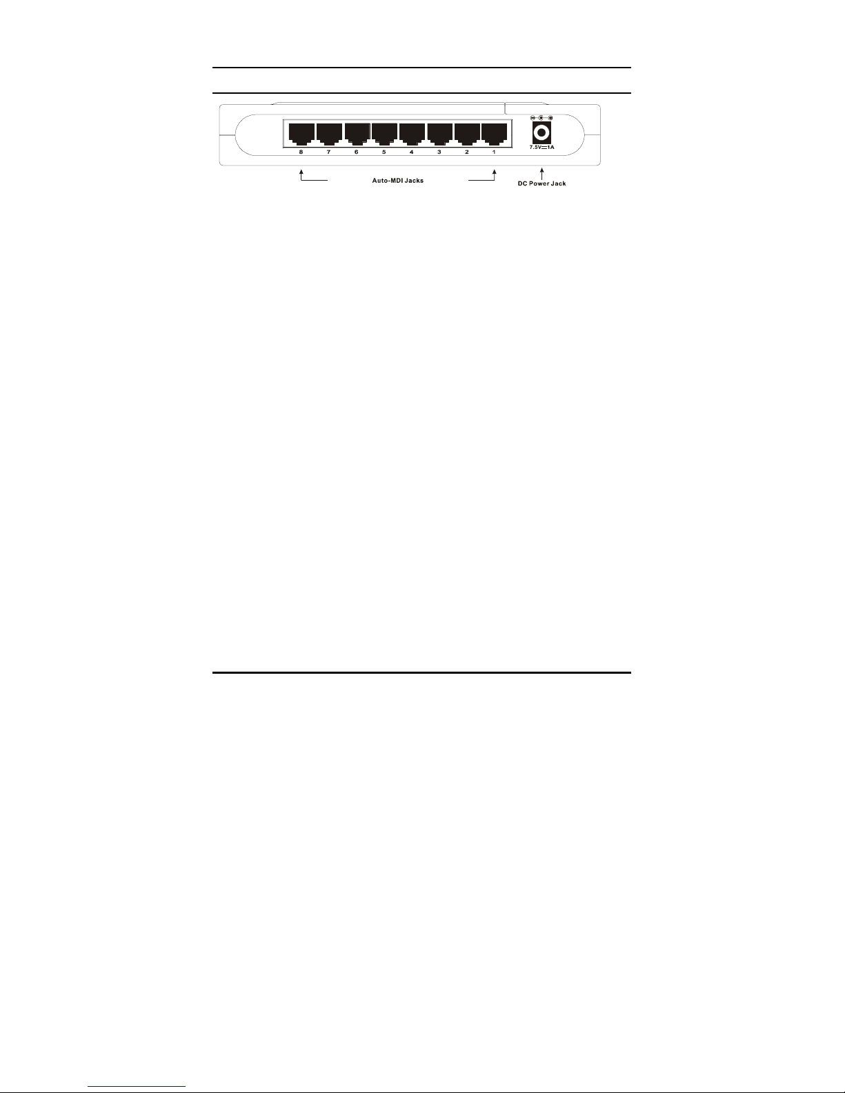
Rear Panel
DSS-8+ 10/100Mbps Fast Ethernet Switch
Auto MDI/MDI-X Ports:
All ports support automatic MDI/MDI-X cable-type detection, which
eliminates the issue of choosing the right cable (Crossover or
Straight-Through). The Auto MDI/MDI-X function makes it simple to
connect to the Switch using either a Crossover or Straight-Through
CAT5 cable into any port—the choice is yours.
DC Power Jack:
Power is supplied through an external DC power adapter. Check
the technical specification section for information about the DC
power input voltage.
Since the DSS-8+ does not include a power button, plugging its
power adapter into a power outlet will immediately power it on.
8
Page 11

CONNECTING THE DSS-8+
Computer to DSS-8+
A computer can be connected to the DSS-8+ via a two-pair
Category 3, 4, 5 UTP/STP Straight-Through or Crossover cable. A
computer equipped with a RJ-45 10/100Mbps port can be
connected to any of the eight DSS-8+ ports.
The LED indicators for the computer connection depend on the
capability of the computer’s Ethernet card. If the LED indicators are
not lit after making a proper connection, check the computer’s
Ethernet card, the cable, or the DSS-8+’s conditions and
connections.
Hub to DSS-8+
A hub (10BASE-T or 100BASE-TX) can be connected to the DSS8+ via a two-pair Category 3, 4, or 5 UTP/STP Straight-Through or
Crossover cable. For 100Mbps operation a Category 5 cable must
be used. The connection is accomplished from any port of the hub
to any port of the DSS-8+.
DSS-8+ to other devices
The DSS-8+ can be connected to another switch or other devices
(routers, bridges, etc.) via a two-pair Category 3, 4, 5 UTP/STP
Straight-Through or Crossover cable. A Category 5 cable must be
used for 100Mbps operation. The connection can be accomplished
from any (MDI-X) port on the DSS-8+ to any of the 10Mbps or
100Mbps (MDI-X) ports on another switch or other devices.
9
Page 12

Port Speed & Duplex Mode
After plugging the selected cable to a specific port, the system uses
auto-negotiation to determine the transmission mode, autodetecting the network speed (10Mbps or 100Mbps) for any new
twisted-pair connection.
If the attached device does not support auto-negotiation or has
auto-negotiation disabled, an auto-sensing process is initiated to
select the speed and half-duplex mode is selected.
10
Page 13
MOUNTING THE SWITCH ON A WALL
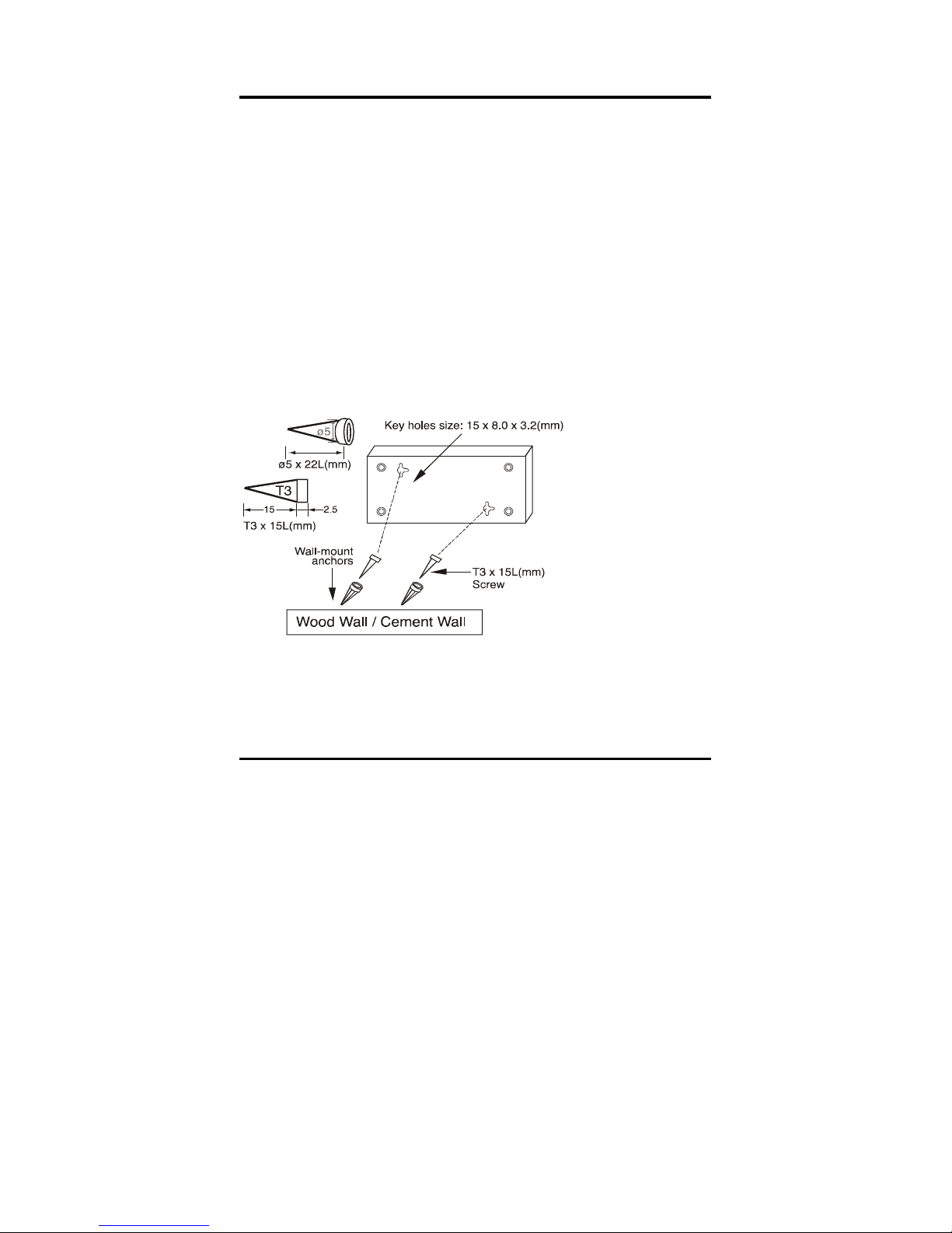
The DSS-8+ can also be mounted on a wall. Two mounting slots
are provided on the bottom of the switch for this purpose. Please
make sure that the front panel is exposed in order to view the
LEDs. Please refer to the illustration below:
A.) Mounting on a cement wall
1. Mount the Nylon screw anchors into a cement wall.
2. Drive the T3 x 15L screws into the Nylon screw anchors.
3. Hook the mounting holes of the switch back on the
screws; you have completed the wall-mount.
B.) Mounting on a wood wall
1. Drive the T3 x 15 L screws into the wood wall.
2. Hook the mounting holes of the switch back on the
screws; you have completed the wall-mount.
(1) 3/4 inch minimum
for woo d wall
(2) 3 inch minimum
for cement wall.
11
Page 14
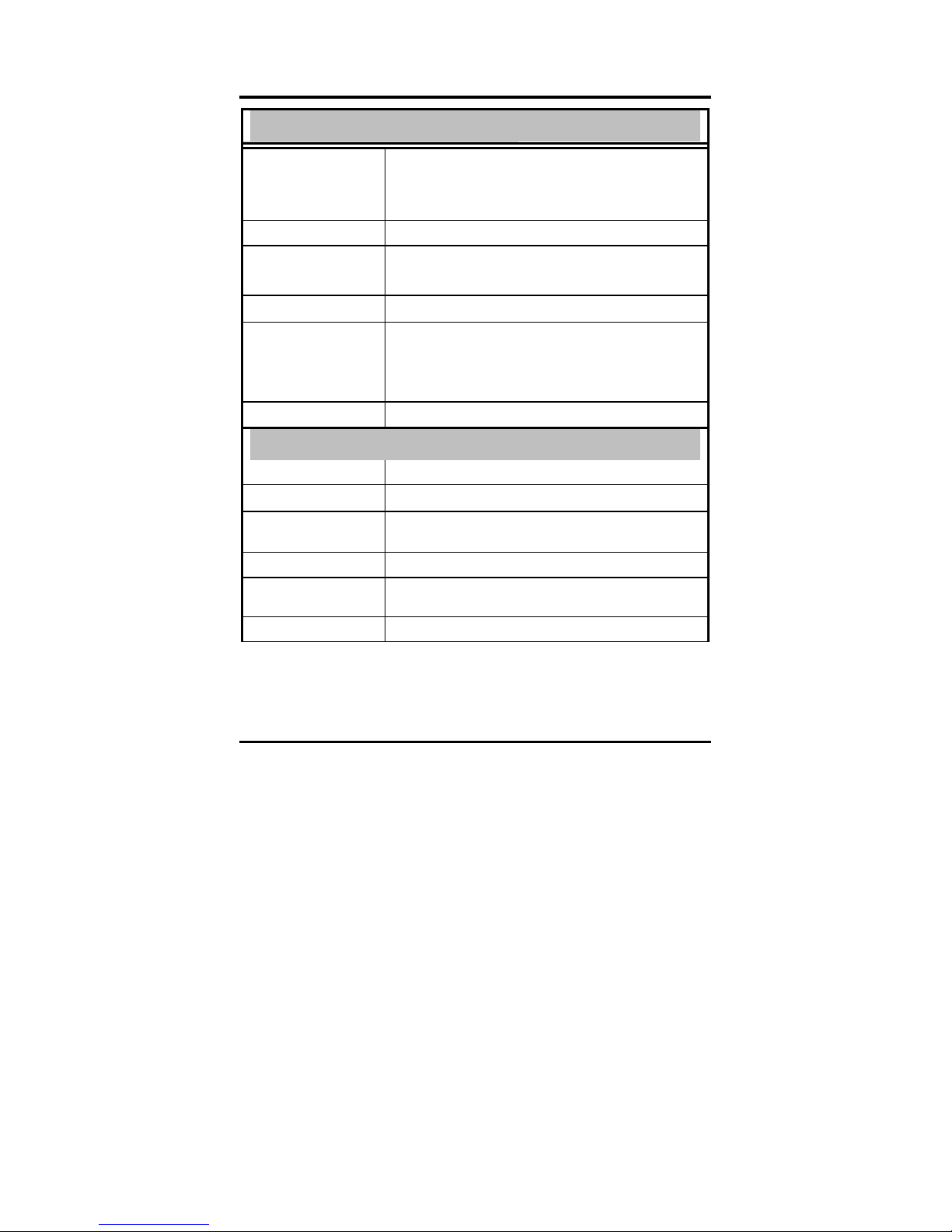
TECHNICAL SPECIFICATIONS
General
Standards IEEE 802.3 10BASE-T Ethernet
IEEE 802.3u 100BASE-TX Fast Ethernet
IEEE 802.3x Flow Control
Protocol CSMA/CD
Data Transfer Rate Ethernet: 10Mbps (half duplex), 20Mbps (full-duplex)
Fast Ethernet: 100Mbps
Topology Star
(half duplex), 200Mbps (full- duplex)
Network Cables 10BASET: 2-pair UTP Cat. 3,4,5 (100 m), EIA/TIA- 568
100BASE-TX: 2-pair UTP Cat. 5 (100 m), EIA/TIA-568
Number of Ports
8 x 10/100Mbps auto-negotiation, auto MDI-X ports
100-ohm STP (100 m)
100-ohm STP (100 m)
Physical and Environmental
DC inputs
Power Consumption
Temperature
Humidity Operating: 10% ~ 90%, Storage: 5% ~ 90%
Dimensions 192.5 x 118.5 x 32 mm (W x H x D) (approx. 7.5 x 4.5
EMI: FCC Class B, CE Mark A, VCCI-II
DC 7.5V / 1A
3.37 Watts (Max)
Operating: 0° ~ 50° C (32º to 122º F), Storage: -10° ~
70° C (14ºto 158º F)
x 1.25 inches)
12
Page 15
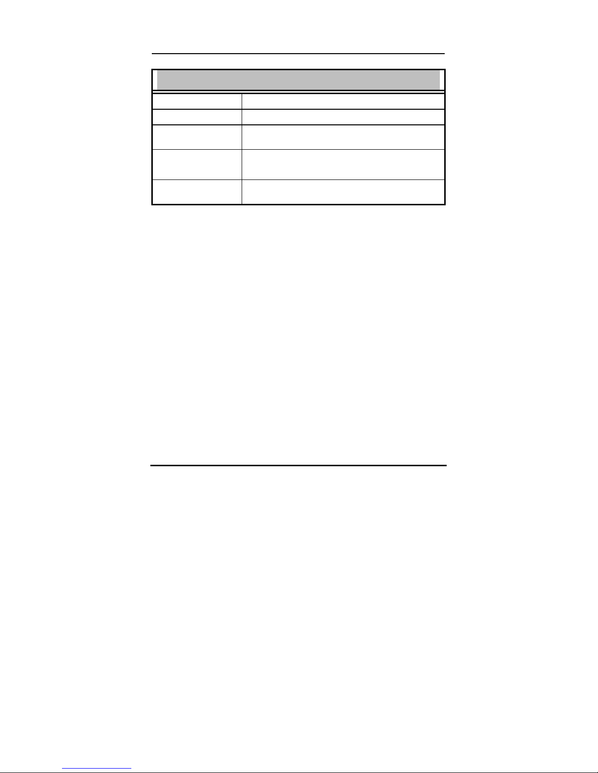
Performance
Transmission Method: Store-and-forward
RAM Buffer 64 Kbytes per device
Filtering Address
Table
Packet Filtering /
Forwarding Rate:
MAC Address
Learning:
1000 entries per device
10Mbps Ethernet: 14,880/pps
100Mbps Fast Ethernet: 148,800/pps
Automatic update
13
Page 16
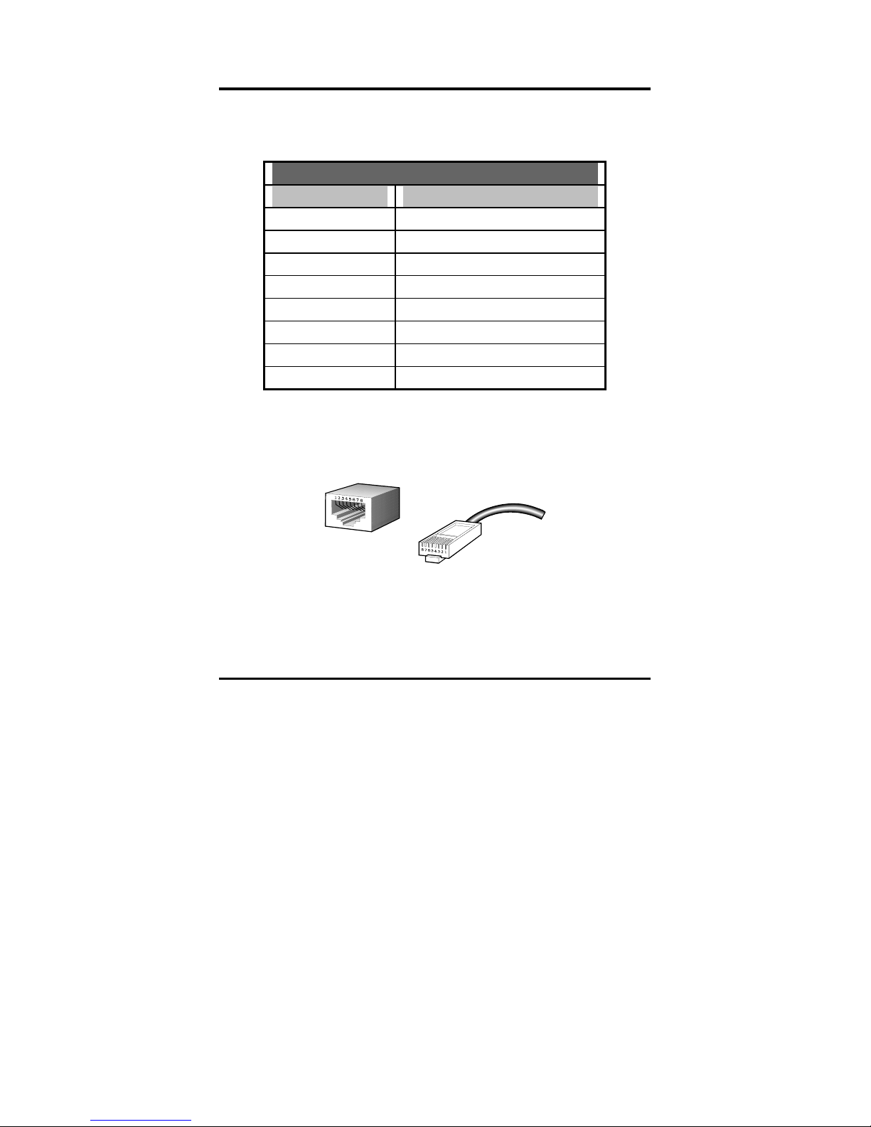
RJ-45 PIN SPECIFICATION
The following diagram and tables show the standard RJ-45
receptacle/connector and their pin assignments.
RJ-45 Connector pin assignment
Contact Media Direct Interface Signal
1 Tx + (transmit)
2 Tx - (transmit)
3 Rx + (receive)
4 Not used
5 Not used
6 Rx - (receive)
7 Not used
8 Not used
RJ-45 pin assignment
Standard RJ-45 receptacle/connector
14
Page 17

WARRANTY
Subject to the terms and conditions set forth herein, D-Link Systems, Inc. (“D-Link”)
provides this Limited warranty for its product only to the person or entity that
originally purchased the product from:
D-Link or its authorized reseller or distributor and
Products purchased and delivered within the fifty states of the United States,
the District of Columbia, U.S. Possessions or Protectorates, U.S. Military
Installations, addresses with an APO or FPO.
Limited Warranty: D-Link warrants that the hardware portion of the D-Link products
described below will be free from material defects in workmanship and materials
from the date of original retail purchase of the product, for the period set forth below
applicable to the product type (“Warranty Period”), except as otherwise stated
herein.
5-Year Limited Warranty for the Product(s) is defined as follows:
Hardware (excluding power supplies and fans) Five (5) Years
Power Supplies and Fans Three (3) Year
Spare parts and spare kits Ninety (90) days
D-Link’s sole obligation shall be to repair or replace the defective Hardware during
the Warranty Period at no charge to the original owner or to refund at D-Link’s sole
discretion. Such repair or replacement will be rendered by D-Link at an Authorized
D-Link Service Office. The replacement Hardware need not be new or have an
identical make, model or part. D-Link may in its sole discretion replace the defective
Hardware (or any part thereof) with any reconditioned product that D-Link
reasonably determines is substantially equivalent (or superior) in all material
respects to the defective Hardware. Repaired or replacement Hardware will be
warranted for the remainder of the original Warranty Period from the date of original
retail purchase. If a material defect is incapable of correction, or if D-Link
determines in its sole discretion that it is not practical to repair or replace the
defective Hardware, the price paid by the original purchaser for the defective
Hardware will be refunded by D-Link upon return to D-Link of the defective
Hardware. All Hardware (or part thereof) that is replaced by D-Link, or for which the
purchase price is refunded, shall become the property of D-Link upon replacement
or refund.
Limited Software Warranty: D-Link warrants that the software portion of the
product (“Software”) will substantially conform to D-Link’s then current functional
specifications for the Software, as set forth in the applicable documentation, from the
date of original retail purchase of the Software for a period of ninety (90) days
(“Warranty Period”), provided that the Software is properly installed on approved
hardware and operated as contemplated in its documentation. D-Link further
warrants that, during the Warranty Period, the magnetic media on which D-Link
delivers the Software will be free of physical defects. D-Link’s sole obligation shall
be to replace the non-conforming Software (or defective media) with software that
substantially conforms to D-Link’s functional specifications for the Software or to
refund at D-Link’s sole discretion. Except as otherwise agreed by D-Link in writing,
the replacement Software is provided only to the original licensee, and is subject to
the terms and conditions of the license granted by D-Link for the Software. Software
15
Page 18

will be warranted for the remainder of the original Warranty Period from the date or
original retail purchase. If a material non-conformance is incapable of correction, or
if D-Link determines in its sole discretion that it is not practical to replace the nonconforming Software, the price paid by the original licensee for the non-conforming
Software will be refunded by D-Link; provided that the non-conforming Software (and
all copies thereof) is first returned to D-Link. The license granted respecting any
Software for which a refund is given automatically terminates.
Non-Applicability of Warranty: The Limited Warranty provided hereunder for
hardware and software of D-Link's products, will not be applied to and does not
cover any product purchased through the inventory clearance or liquidation sale or
other sales in which D-Link, the sellers, or the liquidators expressly disclaim their
warranty obligation pertaining to the product and in that case, the product is being
sold "As-Is" without any warranty whatsoever including, without limitation, the Limited
Warranty as described herein, notwithstanding anything stated herein to the
contrary.
Submitting A Claim: Any claim under this limited warranty must be submitted in
writing before the end of the Warranty Period to an Authorized D-Link Service Office.
The customer must submit as part of the claim a written description of the
Hardware defect or Software nonconformance in sufficient detail to allow D-Link
to confirm the same.
The original product owner must obtain a Return Material Authorization (“RMA”)
number from the Authorized D-Link Service Office and, if requested, provide
written proof of purchase of the product (such as a copy of the dated purchase
invoice for the product) before the warranty service is provided.
After an RMA number is issued, the defective product must be packaged
securely in the original or other suitable shipping package to ensure that it will
not be damaged in transit, and the RMA number must be prominently marked
on the outside of the package. Do not include any manuals or accessories in
the shipping package. D-Link will only replace the defective portion of the
Product and will not ship back any accessories.
The customer is responsible for all shipping charges to D-Link. No Charge on
Delivery (“COD”) is allowed. Products sent COD will either be rejected by DLink or become the property of D-Link. Products should be fully insured by the
customer and shipped to D-Link Systems, Inc., 17595 Mt. Herrmann Street,
Fountain Valley, CA 92708. D-Link will not be held responsible for any
packages that are lost in transit to D-Link. The repaired or replaced packages
will be shipped via UPS Ground or any common carrier selected by D-Link, with
shipping charges prepaid. Expedited shipping is available if shipping charges
are prepaid by the customer.
D-Link may reject or return any product that is not packaged and shipped in strict
compliance with the foregoing requirements, or for which an RMA number is not
visible from the outside of the package. The product owner agrees to pay D-Link’s
reasonable handling and return shipping charges for any product that is not
packaged and shipped in accordance with the foregoing requirements, or that is
determined by D-Link not to be defective or non-conforming.
What Is Not Covered: This limited warranty provided by D-Link does not cover:
Products, if in D-Link’s judgment, have been subjected to abuse, accident, alteration,
modification, tampering, negligence, misuse, faulty installation, lack of reasonable
care, repair or service in any way that is not contemplated in the documentation for
16
Page 19

the product, or if the model or serial number has been altered, tampered with,
defaced or removed; Initial installation, installation and removal of the product for
repair, and shipping costs; Operational adjustments covered in the operating manual
for the product, and normal maintenance; Damage that occurs in shipment, due to
act of God, failures due to power surge, and cosmetic damage; Any hardware,
software, firmware or other products or services provided by anyone other than DLink; Products that have been purchased from inventory clearance or liquidation
sales or other sales in which D-Link, the sellers, or the liquidators expressly disclaim
their warranty obligation pertaining to the product. Repair by anyo ne other than DLink or an Authorized D-Link Service Office will void this Warranty.
Disclaimer of Other Warranties: EXCEPT FOR THE LIMITED WARRANTY
SPECIFIED HEREIN, THE PRODUCT IS PROVIDED “AS-IS” WITHOUT ANY
WARRANTY OF ANY KIND WHATSOEVER INCLUDING, WITHOUT LIMITATION,
ANY WARRANTY OF MERCHANTABILITY, FITNESS FOR A PARTICULAR
PURPOSE AND NON-INFRINGEMENT. IF ANY IMPLIED WARRANTY CANNOT
BE DISCLAIMED IN ANY TERRITORY WHERE A PRODUCT IS SOLD, THE
DURATION OF SUCH IMPLIED WARRANTY SHALL BE LIMITED TO NINETY (90)
DAYS. EXCEPT AS EXPRESSLY COVERED UNDER THE LIMITED WARRANTY
PROVIDED HEREIN, THE ENTIRE RISK AS TO THE QUALITY, SELECTION AND
PERFORMANCE OF THE PRODUCT IS WITH THE PURCHASER OF THE
PRODUCT.
Limitation of Liability: TO THE MAXIMUM EXTENT PERMITTED BY LAW, D-
LINK IS NOT LIABLE UNDER ANY CONTRACT, NEGLIGENCE, STRICT
LIABILITY OR OTHER LEGAL OR EQUITABLE THEORY FOR ANY LOSS OF USE
OF THE PRODUCT, INCONVENIENCE OR DAMAGES OF ANY CHARACTER,
WHETHER DIRECT, SPECIAL, INCIDENTAL OR CONSEQUENTIAL (INCLUDING,
BUT NOT LIMITED TO, DAMAGES FOR LOSS OF GOODWILL, LOSS OF
REVENUE OR PROFIT, WORK STOPPAGE, COMPUTER FAILURE OR
MALFUNCTION, FAILURE OF OTHER EQUIPMENT OR COMPUTER PROGRAMS
TO WHICH D-LINK’S PRODUCT IS CONNECTED WITH, LOSS OF INFORMATION
OR DATA CONTAINED IN, STORED ON, OR INTEGRATED WITH ANY PRODUCT
RETURNED TO D-LINK FOR WARRANTY SERVICE) RESULTING FROM THE
USE OF THE PRODUCT, RELATING TO WARRANTY SERVICE, OR ARISING
OUT OF ANY BREACH OF THIS LIMITED WARRANTY, EVEN IF D-LINK HAS
BEEN ADVISED OF THE POSSIBILITY OF SUCH DAMAGES. THE SOLE
REMEDY FOR A BREACH OF THE FOREGOING LIMITED WARRANTY IS
REPAIR, REPLACEMENT OR REFUND OF THE DEFECTIVE OR NONCONFORMING PRODUCT. THE MAXIMUM LIABILITY OF D-LINK UNDER THIS
WARRANTY IS LIMITED TO THE PURCHASE PRICE OF THE PRODUCT
COVERED BY THE WARRANTY. THE FOREGOING EXPRESS WRITTEN
WARRANTIES AND REMEDIES ARE EXCLUSIVE AND ARE IN LIEU OF ANY
OTHER WARRANTIES OR REMEDIES, EXPRESS, IMPLIED OR STATUTORY
Governing Law: This Limited Warranty shall be governed by the laws of the state
of California. Some states do not allow exclusion or limitation of incidental or
consequential damages, or limitations on how long an implied warranty lasts, so the
foregoing limitations and exclusions may not apply. This limited warranty provides
specific legal rights and the product owner may also have other rights which vary
from state to state.
Trademarks: D-Link is a registered trademark of D-Link Systems, Inc. Other
trademarks or registered trademarks are the property of their respective
17
Page 20

manufacturers or owners.
Copyright Statement: No part of this publication or documentation accompanying
this Product may be reproduced in any form or by any means or used to make any
derivative such as translation, transformation, or adaptation without permission from
D-Link Corporation/D-Link Systems, Inc., as stipulated by the United States
Copyright Act of 1976. Contents are subject to change without prior notice.
Copyright
CE Mark Warning: This is a Class B product. In a domestic environment, this
product may cause radio interference, in which case the user may be required to
take adequate measures.
FCC Statement: This equipment has been tested and found to comply with the
limits for a Class B digital device, pursuant to part 15 of the FCC Rules. These limits
are designed to provide reasonable protection against harmful interference in a
residential installation. This equipment generates uses and can radiate radio
frequency energy and, if not installed and used in accordance with the instructions,
may cause harmful interference to radio communication. However, there is no
guarantee that interference will not occur in a particular installation. If this equipment
does cause harmful interference to radio or television reception, which can be
determined by turning the equipment off and on, the user is encouraged to try to
correct the interference by one or more of the following measures:
Reorient or relocate the receiving antenna.
Increase the separation between the equipment and receiver.
Connect the equipment into an outlet on a circuit different from that to which the
Consult the dealer or an experienced radio/TV technician for help.
©
2002 by D-Link Corporation/D-Link Systems, Inc. All rights reserved.
receiver is connected.
18
Page 21

R
EGISTRATION
Register your product on-line at:
http://support.dlink.com/register
Product registration is entirely voluntary and failure to
complete or return this form will not diminish your
warranty rights.
19
Page 22

TECHNICAL SUPPORT
You can find software updates and user documentation on the D-Link website.
D-Link provides free technical support for customers within the United States and
within Canada for the duration of the warranty period on this product.
U.S. and Canadian customers can contact D-Link technical support through our
website, or by phone.
Tech Support for customers within the United States:
D-Link Technical Support over the Telephone:
(877) 453-5465
24 hours a day, seven days a week.
D-Link Technical Support over the Internet:
http://support.dlink.com
email:[email protected]
Tech Support for customers within Canada:
D-Link Technical Support over the Telephone:
(800) 361-5265
Monday to Friday 8:30am to 9:00pm EST
D-Link Technical Support over the Internet:
http://support.dlink.ca
email:[email protected]
Technical Support
P/N:1907DS1008*6006
20
 Loading...