

Page 1
Building Networks for People
Unified Services Router
User Manual
DSR-150 / 150N / 250 / 250N / 500 / 500N /
1000 / 1000N
Ver. 1.05
Small Business Gateway Solution
Page 2

User Manual
Unified Services Router
D-Link Corporation
Copyright © 2012.
http://www.dlink.com
Page 3

Unified Services Router User Manual
User Manual
DSR-150 / 150N /250 / 250N / DSR-500 / 500N / 1000 / 1000N
Unified Services Router
Version 1.05
Copyright © 2012
Copyright Notice
This publication, including all photographs , illus trations and software, is protected under
international copyright laws, with all rights reserved. Neither this manual, nor any of the
material contained herein, may be reproduced without written cons ent of the author.
Disclaimer
The information in this document is subject to change without notice. The manufacturer makes
no representations or warranties with respect to the contents hereof and specifically disclaim
any implied warranties of merchantability or fitnes s for any particular purpose. The
manufacturer reserves the right to revise this publication and to make changes from time to
time in the content hereof without obligation of the manufacturer to notify any pers on of s uch
revision or changes .
Limitations of Liability
UNDER NO CIRCUMSTANCES SHALL D-LINK OR ITS SUPPLIERS BE LIABLE FOR
DAMAGES OF ANY CHARACTER (E.G. DA MAGES FOR LOSS OF PROFIT, SOFTWARE
RESTORATION, WORK STOPPAGE, LOSS OF SAVED DATA OR ANY OTHER
COMMERCIAL DAMAGES OR LOSSES) RESULTING FROM THE A PPLICATION OR
IMPROPER USE OF THE D-LINK PRODUCT OR FAILURE OF THE PRODUCT, EVEN IF
D-LINK IS INFORMED OF THE POSSIBILITY OF SUCH DA MAGES. FURTHERMORE, DLINK WILL NOT BE LIABLE FOR THIRD-PA RTY CLAIMS AGAINST CUSTOMER FOR
LOSSES OR DAMAGES. D-LINK W ILL IN NO EVENT BE LIABLE FOR ANY DAMA GES
IN EXCESS OF THE AMOUNT D-LINK RECEIVED FROM THE END-USER FOR THE
PRODUCT.
1
Page 4

Unified Services Router User Manual
Table of Contents
Chapter 1. Introduction.......................................................................................................................................... 11
1.1 About this User Manual .................................................................................................... 12
1.2 Typographical Conventions............................................................................................. 12
Chapter 2. Configuring Your Network: LAN Setup ...................................................................................... 13
2.1 LAN Configuration .............................................................................................................. 13
2.1.1 LAN DHCP Reserved IPs ................................................................................................ 16
2.1.2 LAN DHCP Leased Clients.............................................................................................. 17
2.1.3 LAN Configuration in an IPv6 Network........................................................................ 18
2.1.4 Configuring IPv6 Router Advertisements ................................................................... 21
2.2 VLAN Configuration ........................................................................................................... 23
2.2.1 Associating VLANs to ports............................................................................................. 24
2.2.2 Multiple VLAN Subnets ..................................................................................................... 26
2.2.3 VLAN configuration ............................................................................................................ 27
2.3 Configurable Port: DMZ Setup ....................................................................................... 28
2.4 Universal Plug and Play (UPnP).................................................................................... 29
2.5 Captive Portal....................................................................................................................... 31
2.6 Captive portal setup ........................................................................................................... 32
Chapter 3. Connecting to the Internet: WAN Setup .................................................................................... 35
3.1 Internet Setup Wizard........................................................................................................ 35
3.2 WAN Configuration............................................................................................................. 36
3.2.1 WAN Port IP address ........................................................................................................ 37
3.2.2 WAN DNS Servers ............................................................................................................. 37
3.2.3 DHCP WAN .......................................................................................................................... 37
3.2.4 PPPoE .................................................................................................................................... 38
3.2.5 Russia L2TP and PPTP WAN ........................................................................................ 41
3.2.6 Russia Dual Access PPPoE............................................................................................ 42
3.2.7 WAN Configuration in an IPv6 Network ...................................................................... 43
3.2.8 Checking WAN Status....................................................................................................... 45
3.3 Bandwidth Controls ............................................................................................................ 47
3.4 Features with Multiple WAN Links ................................................................................ 49
3.4.1 Auto Failover ........................................................................................................................ 49
3.4.2 Load Balancing .................................................................................................................... 50
3.4.3 Protocol Bindings ................................................................................................................ 52
3.5 Routing Configuration........................................................................................................ 53
3.5.1 Routing Mode ....................................................................................................................... 53
3.5.2 Dynamic Routing (RIP) ..................................................................................................... 56
3.5.3 Static Routing ....................................................................................................................... 57
3.5.4 OSPFv2 .................................................................................................................................. 58
3.5.5 OSPFv3 .................................................................................................................................. 60
3.5.6 6to4 Tunneling ..................................................................................................................... 62
3.5.7 ISATAP Tunnels.................................................................................................................. 63
3.6 Configurable Port - WAN Option ................................................................................... 64
3.7 WAN 3 (3G) Configuration............................................................................................... 64
3.8 WAN Port Settings.............................................................................................................. 66
2
Page 5

Unified Services Router User Manual
Chapter 4. Wireless Access Point Setup ........................................................................................................ 68
4.1 Wireless Settings Wizard ................................................................................................. 68
4.1.1 Wireless Network Setup Wizard .................................................................................... 69
4.1.2 Add Wireless Device with WPS ..................................................................................... 69
4.1.3 Manual Wireless Network Setup ................................................................................... 70
4.2 Wireless Profiles.................................................................................................................. 70
4.2.1 WEP Security ....................................................................................................................... 71
4.2.2 WPA or WPA2 with PSK .................................................................................................. 73
4.2.3 RADIUS Authentication .................................................................................................... 73
4.3 Creating and Using Access Points ............................................................................... 75
4.3.1 Primary benefits of Virtual APs: ..................................................................................... 77
4.4 Tuning Radio Specific Settings ...................................................................................... 78
4.5 WMM ....................................................................................................................................... 79
4.6 Wireless distribution system (WDS) ............................................................................. 80
4.7 Advanced Wireless Settings ........................................................................................... 81
4.8 Wi-Fi Protected Setup (WPS) ......................................................................................... 82
Chapter 5. Securing the Private Network ....................................................................................................... 85
5.1 Firewall Rules....................................................................................................................... 85
5.2 Defining Rule Schedules .................................................................................................. 86
5.3 Configuring Firewall Rules............................................................................................... 87
5.4 Configuring IPv6 Firewall Rules..................................................................................... 92
5.4.1 Firewall Rule Configuration Examples......................................................................... 93
5.5 Security on Custom Services.......................................................................................... 97
5.6 ALG support.......................................................................................................................... 99
5.7 VPN Passthrough for Firewall ...................................................................................... 100
5.8 Application Rules .............................................................................................................. 101
5.9 Web Content Filtering...................................................................................................... 102
5.9.1 Content Filtering ................................................................................................................ 102
5.9.2 Approved URLs ................................................................................................................. 103
5.9.3 Blocked Keywords ............................................................................................................ 104
5.9.4 Export Web Filter .............................................................................................................. 105
5.10 IP/MAC Binding ................................................................................................................. 106
5.11 Intrusion Prevention (IPS).............................................................................................. 107
5.12 Protecting from Internet Attacks .................................................................................. 108
Chapter 6. IPsec / PPTP / L2TP VPN ............................................................................................................ 111
6.1 VPN Wizard ........................................................................................................................ 113
6.2 Configuring IPsec Policies ............................................................................................. 115
6.2.1 Extended Authentication (XAUTH) ............................................................................. 119
6.2.2 Internet over IPSec tunnel ............................................................................................. 120
6.3 Configuring VPN clients.................................................................................................. 120
6.4 PPTP / L2TP Tunnels...................................................................................................... 120
6.4.1 PPTP Tunnel Support ..................................................................................................... 120
6.4.2 L2TP Tunnel Support ...................................................................................................... 122
6.4.3 OpenVPN Support ............................................................................................................ 123
6.4.4 OpenVPN Remote Network .......................................................................................... 125
6.4.5 OpenVPN Authentication ............................................................................................... 126
3
Page 6

Unified Services Router User Manual
Chapter 7. SSL VPN ............................................................................................................................................ 129
7.1 Groups and Users............................................................................................................. 131
7.1.1 Users and Passwords ..................................................................................................... 137
7.2 Using SSL VPN Policies................................................................................................. 138
7.2.1 Using Network Resources ............................................................................................. 141
7.3 Application Port Forwarding .......................................................................................... 142
7.4 SSL VPN Client Configuration...................................................................................... 144
7.5 User Portal .......................................................................................................................... 147
7.5.1 Creating Portal Layouts .................................................................................................. 147
Chapter 8. Advanced Configuration Tools ................................................................................................... 150
8.1 USB Device Setup ............................................................................................................ 150
8.2 USB share port .................................................................................................................. 151
8.3 SMS service........................................................................................................................ 153
8.4 Authentication Certificates ............................................................................................. 154
8.5 Advanced Switch Configuration ................................................................................... 156
Chapter 9. Administration & Management ................................................................................................... 157
9.1 Configuration Access Control ....................................................................................... 157
9.1.1 Admin Settings................................................................................................................... 157
9.1.2 Remote Management ...................................................................................................... 158
9.1.3 CLI Access .......................................................................................................................... 159
9.2 SNMP Configuration ........................................................................................................ 159
9.3 Configuring Time Zone and NTP................................................................................. 161
9.4 Log Configuration.............................................................................................................. 162
9.4.1 Defining What to Log ....................................................................................................... 162
9.4.2 Sending Logs to E-mail or Syslog ............................................................................... 167
9.4.3 Event Log Viewer in GUI ................................................................................................ 169
9.5 Backing up and Restoring Configuration Settings................................................. 170
9.6 Upgrading Router Firmware.......................................................................................... 171
9.7 Upgrading Router Firmware via USB......................................................................... 172
9.8 Dynamic DNS Setup ........................................................................................................ 173
9.9 Using Diagnostic Tools ................................................................................................... 174
9.9.1 Ping........................................................................................................................................ 175
9.9.2 Trace Route ........................................................................................................................ 175
9.9.3 DNS Lookup ....................................................................................................................... 176
9.9.4 Router Options................................................................................................................... 176
9.10 Localization ......................................................................................................................... 177
Chapter 10. Router Status and Statistics ........................................................................................................ 178
10.1 System Overview .............................................................................................................. 178
10.1.1 Device Status ..................................................................................................................... 178
10.1.2 Resource Utilization ......................................................................................................... 180
10.2 Traffic Statistics ................................................................................................................. 183
10.2.1 Wired Port Statistics......................................................................................................... 183
10.2.2 Wireless Statistics............................................................................................................. 184
10.3 Active Connections........................................................................................................... 185
10.3.1 Sessions through the Router ........................................................................................ 185
4
Page 7

Unified Services Router User Manual
10.3.2 Wireless Clients................................................................................................................. 187
10.3.3 LAN Clients ......................................................................................................................... 187
10.3.4 Active VPN Tunnels ......................................................................................................... 188
Chapter 11. Trouble Shooting ............................................................................................................................. 190
11.1 Internet connection ........................................................................................................... 190
11.2 Date and time ..................................................................................................................... 192
11.3 Pinging to Test LAN Connectivity................................................................................ 192
11.3.1 Testing the LAN path from your PC to your router................................................ 192
11.3.2 Testing the LAN path from your PC to a remote device...................................... 193
11.4 Restoring factory-default configuration settings ..................................................... 194
Chapter 12. Credits ................................................................................................................................................. 195
Appendix A. Glossary ............................................................................................................................................. 196
Appendix B. Factory Default Settings................................................................................................................ 199
Appendix C. Standard Services Available for Port Forwarding & Firewall Configuration................ 200
Appendix D. Log Output Reference ................................................................................................................... 201
Appendix E. RJ-45 Pin-outs.................................................................................................................................. 255
Appendix F. Product Statement .......................................................................................................................... 256
5
Page 8

Unified Services Router User Manual
List of Figures
Figure 1: Setup page for LAN TCP/IP settings................................................................................................. 15
Figure 2: LAN DHCP Reserved IPs ..................................................................................................................... 17
Figure 3: LAN DHCP Leased Clients................................................................................................................... 18
Figure 4: IPv6 LAN and DHCPv6 configuration ............................................................................................... 19
Figure 5: Configuring the Router Advertisement Daemon ........................................................................... 22
Figure 6: IPv6 Advertisement Prefix settings .................................................................................................... 23
Figure 7: Adding VLAN memberships to the LAN ........................................................................................... 24
Figure 8: Port VLAN list ............................................................................................................................................ 25
Figure 9: Configuring VLAN membership for a port........................................................................................ 26
Figure 10: Multiple VLAN Subnets........................................................................................................................ 27
Figure 11: VLAN Configuration .............................................................................................................................. 28
Figure 12: DMZ configuration ................................................................................................................................. 29
Figure 13: UPnP Configuration .............................................................................................................................. 30
Figure 14: Active Runtime sessions ..................................................................................................................... 32
Figure 15: Captive Portal Setup............................................................................................................................. 33
Figure 16: Customized Captive Portal Setup .................................................................................................... 34
Figure 17: Internet Connection Setup Wizard................................................................................................... 35
Figure 18: Manual WAN configuration................................................................................................................. 38
Figure 19: PPPoE configuration for standard ISPs ......................................................................................... 39
Figure 20: WAN configuration for Japanese Multiple PPPoE (part 1)...................................................... 40
Figure 21: WAN configuration for Multiple PPPoE (part 2) .......................................................................... 41
Figure 22: Russia L2TP ISP configuration ......................................................................................................... 42
Figure 23: Russia Dual access PPPoE configuration .................................................................................... 43
Figure 24: IPv6 WAN Setup page ......................................................................................................................... 44
Figure 25: Connection Status information for both WAN ports................................................................... 46
Figure 26: List of Configured Bandwidth Profiles ............................................................................................ 47
Figure 27: Bandwidth Profile Configuration page ............................................................................................ 48
Figure 28: Traffic Selector Configuration............................................................................................................ 49
Figure 29: Load Balancing is available when multiple WAN ports are configured and Protocol
Bindings have been defined ............................................................................................................... 52
Figure 30: Protocol binding setup to associate a service and/or LAN source to a WAN and/or
destination network................................................................................................................................ 53
Figure 31: Routing Mode is used to configure traffic routing between WAN and LAN, as well as
Dynamic routing (RIP) .......................................................................................................................... 55
Figure 32: Static route configuration fields......................................................................................................... 58
6
Page 9

Unified Services Router User Manual
Figure 33: OSPFv2 configured parameters ....................................................................................................... 59
Figure 34: OSPFv2 configuration .......................................................................................................................... 60
Figure 35: OSPFv3 configured parameters ....................................................................................................... 61
Figure 36: OSPFv3 configuration .......................................................................................................................... 62
Figure 37: 6 to 4 tunneling ....................................................................................................................................... 63
Figure 38: ISATAP Tunnels Configuration ......................................................................................................... 64
Figure 39: WAN3 configuration for 3G internet ................................................................................................ 66
Figure 40: Physical WAN port settings................................................................................................................ 67
Figure 41: Wireless Network Setup Wizards..................................................................................................... 69
Figure 42: List of Available Profiles shows the options available to secure the wireless link .......... 71
Figure 43: Profile configuration to set network security................................................................................. 73
Figure 44: RADIUS server (External Authentication) configuration .......................................................... 75
Figure 45: Virtual AP configuration ....................................................................................................................... 76
Figure 46: List of configured access points (Virtual APs) shows one enabled access point on the
radio, broadcasting its SSID ............................................................................................................... 77
Figure 47: Radio card configuration options...................................................................................................... 78
Figure 48: Wi-Fi Multimedia .................................................................................................................................... 79
Figure 49: Wireless Distribution System............................................................................................................. 80
Figure 50: Advanced Wireless communication settings................................................................................ 82
Figure 51: WPS configuration for an AP with WPA/WPA2 profile ............................................................. 83
Figure 52: List of Available Firewall Rules ......................................................................................................... 86
Figure 53: List of Available Schedules to bind to a firewall rule ................................................................. 87
Figure 54: Example where an outbound SNAT rule is used to map an external IP address
(209.156.200.225) to a private DMZ IP address (10.30.30.30) ............................................. 90
Figure 55: The firewall rule configuration page allows you to define the To/From zone, service,
action, schedules, and specify source/destination IP addresses as needed. ................... 91
Figure 56: The IPv6 firewall rule configuration page allows you to define the To/From zone,
service, action, schedules, and specify source/destination IP addresses as needed. .. 92
Figure 57: List of Available IPv6 Firewall Rules ............................................................................................... 93
Figure 58: Schedule configuration for the above example........................................................................... 96
Figure 59: List of user defined services. ............................................................................................................. 98
Figure 60: Custom Services configuration ......................................................................................................... 98
Figure 61: Available ALG support on the router. ........................................................................................... 100
Figure 62: Passthrough options for VPN tunnels .......................................................................................... 101
Figure 63: List of Available Application Rules showing 4 unique rules .................................................. 102
Figure 64: Content Filtering used to block access to proxy servers and prevent ActiveX controls
from being downloaded...................................................................................................................... 103
7
Page 10

Unified Services Router User Manual
Figure 65: Two trusted domains added to the Approved URLs List ....................................................... 104
Figure 66: One keyword added to the block list ............................................................................................. 105
Figure 67: Export Approved URL list ................................................................................................................. 106
Figure 68: The following example binds a LAN host’s MAC Address to an IP address served by
DSR. If there is an IP/MAC Binding violation, the violating packet will be dropped and
logs will be captured............................................................................................................................ 107
Figure 69: Intrusion Prevention features on the router ................................................................................ 108
Figure 70: Protecting the router and LAN from internet attacks ............................................................... 109
Figure 71: Example of Gateway-to-Gateway IPsec VPN tunnel using two DSR routers connected
to the Internet......................................................................................................................................... 111
Figure 72: Example of three IPsec client connections to the internal network through the DSR
IPsec gateway ....................................................................................................................................... 112
Figure 73: VPN Wizard launch screen .............................................................................................................. 113
Figure 74: IPsec policy configuration ................................................................................................................. 116
Figure 75: IPsec policy configuration continued (Auto policy via IKE) ................................................... 117
Figure 76: IPsec policy configuration continued (Auto / Manual Phase 2) ........................................... 119
Figure 77: PPTP tunnel configuration – PPTP Client................................................................................... 121
Figure 78: PPTP VPN connection status.......................................................................................................... 121
Figure 79: PPTP tunnel configuration – PPTP Server ................................................................................. 122
Figure 80: L2TP tunnel configuration – L2TP Server................................................................................... 123
Figure 81: OpenVPN configuration..................................................................................................................... 125
Figure 82: OpenVPN Remote Network ............................................................................................................. 126
Figure 83: OpenVPN Authentication .................................................................................................................. 127
Figure 84: Example of clientless SSL VPN connections to the DSR...................................................... 130
Figure 85: List of groups......................................................................................................................................... 131
Figure 86: User group configuration................................................................................................................... 132
Figure 87: SSLVPN Settings................................................................................................................................. 133
Figure 88: Group login policies options............................................................................................................. 134
Figure 89: Browser policies options ................................................................................................................... 135
Figure 90: IP policies options................................................................................................................................ 136
Figure 91: Available Users with login status and associated Group ....................................................... 137
Figure 92: User configuration options................................................................................................................ 138
Figure 93: List of SSL VPN polices (Global filter).......................................................................................... 139
Figure 94: SSL VPN policy configuration ......................................................................................................... 140
Figure 95: List of configured resources, which are available to assign to SSL VPN policies ........ 142
Figure 96: List of Available Applications for SSL Port Forwarding .......................................................... 144
Figure 97: SSL VPN client adapter and access configuration .................................................................. 145
8
Page 11

Unified Services Router User Manual
Figure 98: Configured client routes only apply in split tunnel mode........................................................ 146
Figure 99: List of configured SSL VPN portals. The configured portal can then be associated with
an authentication domain .................................................................................................................. 147
Figure 100: SSL VPN Portal configuration....................................................................................................... 149
Figure 101: USB Device Detection ..................................................................................................................... 151
Figure 102: USB SharePort................................................................................................................................... 152
Figure 103: SMS Service – Send SMS ............................................................................................................. 153
Figure 104: SMS Service – Receive SMS ....................................................................................................... 154
Figure 105: Certificate summary for IPsec and HTTPS management ................................................... 155
Figure 106: Advanced Switch Settings.............................................................................................................. 156
Figure 107: User Login policy configuration .................................................................................................... 157
Figure 108: Admin Settings ................................................................................................................................... 158
Figure 109: Remote Management from the WAN ......................................................................................... 159
Figure 110: SNMP Users, Traps, and Access Control ................................................................................ 160
Figure 111: SNMP system information for this router .................................................................................. 161
Figure 112: Date, Time, and NTP server setup ............................................................................................. 162
Figure 113: Facility settings for Logging ........................................................................................................... 164
Figure 114: Log configuration options for traffic through router................................................................ 166
Figure 115: IPv6 Log configuration options for traffic through router ..................................................... 167
Figure 116: E-mail configuration as a Remote Logging option................................................................. 168
Figure 117: Syslog server configuration for Remote Logging (continued)............................................ 169
Figure 118: VPN logs displayed in GUI event viewer .................................................................................. 170
Figure 119: Restoring configuration from a saved file will result in the current configuration being
overwritten and a reboot .................................................................................................................... 171
Figure 120: Firmware version information and upgrade option ................................................................ 172
Figure 121: Firmware upgrade and configuration restore/backup via USB.......................................... 173
Figure 122: Dynamic DNS configuration .......................................................................................................... 174
Figure 123: Router diagnostics tools available in the GUI ......................................................................... 175
Figure 124: Sample trace route output.............................................................................................................. 176
Figure 125: Localization ......................................................................................................................................... 177
Figure 126: Device Status display ...................................................................................................................... 179
Figure 127: Device Status display (continued) ............................................................................................... 180
Figure 128: Resource Utilization statistics ....................................................................................................... 181
Figure 129: Resource Utilization data (continued) ........................................................................................ 182
Figure 130: Resource Utilization data (continued) ........................................................................................ 183
Figure 131: Physical port statistics ..................................................................................................................... 184
9
Page 12

Unified Services Router User Manual
Figure 132: AP specific statistics......................................................................................................................... 185
Figure 133: List of current Active Firewall Sessions..................................................................................... 186
Figure 134: List of connected 802.11 clients per AP.................................................................................... 187
Figure 135: List of LAN hosts ............................................................................................................................... 188
Figure 136: List of current Active VPN Sessions ........................................................................................... 189
10
Page 13

Unified Services Router User Manual
Chapter 1. Introduction
D-Link Unified Services Routers offer a s ecure, high performance networking solution
to address the growing needs of small and medium bus iness es. Integrated high -s peed
IEEE 802.11n and 3G wireless technologies offer comparable performance to
traditional wired networks , but with fewer limitations. Optimal network security is
provided via features such as virtual private network (VPN) tunnels, IP Security
(IPs ec), Point-to -Point Tunneling Protocol (PPTP), Layer 2 Tunneling Protocol (L2TP),
and Secure So ckets Layer (SSL). Empower your road warriors with clientless remote
access anywhere and anytime using SSL VPN tunnels .
With the D-Link Unified Services Router you are able to experience a diverse set of
benefits:
Comprehensive Management Capabilities
The DSR-500, DSR-500N, DSR-1000 and DSR-1000N include dual-WAN
Gigabit Ethernet which provides policy -bas ed s ervice management ensuring
maximum productivity for your busines s operations. The failover feature
maintains data traffic without dis connecting when a landline connection is lost.
The Outbound Load Balancing feature adjusts outgoing traffic across two WAN
interfaces and optimizes the system performance resulting in high availability.
The second WAN port can be configured as a DMZ port allowing you to isolate
servers from your LAN.
DSR-150/150N/250 /250N have a single W AN interface, and thus it does not
support Auto Failover and Load Balancing s cenarios.
Superior Wireless Performance
Des igned to deliver s uperior wireless performance, the DSR-500N and DSR1000N include 802.11 a/b/g/n, allowing for operation on either the 2.4 GHz or
5 GHz radio bands . Multiple In Multiple Out (MIMO) technology allows the
DSR-500N and DSR-1000N t o pro v ide h igh d a t a ra t es wit h min imal “d e a d
s p o ts ” t h rou g h o u t t h e wire le s s c o v erage a rea.
DSR-150N, 250N and DSR-500N s upports the 2.4GHz radio band only.
Flexible Deployment Options
The DSR-1000 / 1000N supports Third Generation (3G) Networks via an
extendable USB 3G dongle. This 3G network capability offers an additional
secure data connection for networks that provide critical s ervices . The DSR 1000N can be configured to automatically switch to a 3G network whenever a
phys ical link is lost.
Robust VPN features
A fully featured virtual private network (VPN) provides your mobile workers
and branch offices with a s ecure link to your network. The DSR150/150N/250/ 250N, DSR-500/500N and DSR-1000 /1000N are capable of
simultaneously managing 5, 5, 10, 20 Secure Sockets Layer (SSL) VPN tunnels
res pectively, empowering your mobile users by providing remote access to a
11
Page 14

Unified Services Router User Manual
central corporate databas e. Site -to-site VPN tunnels use IP Security (IPs ec)
Protocol, Point-to-Point Tunneling Protocol (PPTP), or Lay er 2 Tunneling
Protocol (L2TP) to facilitate branch office connectivity through encrypted
virtual links. The DSR-150/ 150N, DSR-250/250N, DSR-500/500N and DSR-
1000/1000N support 10, 25, 35 and 75 s imultaneous IPSec VPN tunnels
res pectively .
Efficient D-Link Green Technology
As a concerned member of the global community, D-Link is devoted to
providing eco-friendly products . D-Link Green WiFi and D-Link Green
Ethernet save power and prevent waste. The D-Link Green WLAN s cheduler
reduces wireles s power automatically during off-peak hours. Likewise the DLink Green Ethernet program adjusts power usage based on the detected cable
length and link s tatus. In addition, compliance with RoHS (Res triction of
Hazardous Substances) and WEEE (Waste Electrical and Electronic Equipment)
directives make D-Link Green certified devices the environmentally responsible
choice.
Support for the 3G wireles s WAN USB dongle is only available for DSR-1000 and
DSR-1000N.
1.1 About this User Manual
This document is a high level manual to allow new D-Link Unified Services Router
users to configure connectivity, setup VPN tunnels, es tablis h firewall rules and
perform general administrative tasks. Typical deployment and use cas e scenarios are
described in each section. For more detailed setup ins tructions and explanations of
each configuration parameter, refer to the online help that can be access ed from each
page in the router GUI.
1.2 Typographical Conventions
The following is a list of the various terms , followed by an example of how that term
is represented in this document:
Product Name – D-Link Unified Services Router.
o Model numbers DSR-500/ 500N/1000/1000N/250/250N/150/150N
GUI Menu Path/GUI Navigation – Monitoring > Router Status
Important note –
12
Page 15

Chapter 2. Configuring Your Network:
LAN Setup
It is assumed that the user has a machine for management connected to the LAN to the
router. The LAN connection may be through the wired Ethernet ports available on the
router, or once the initial setup is complete, the DSR may also be managed through its
wireles s interface as it is bridged with the LAN. A cc e s s t h e ro u te r’s graphical us er
interface (GUI) for management by us ing any web browser, s uch as Microsoft Internet
Explorer or Mozilla Firefox:
Go to http://192.168.10.1 (defa u lt IP ad dres s ) to dis play the ro u t e r’s
management login s creen.
Default login credentials for the management GUI:
Username: admin
Pass word: admin
If t he rou t e r’s LAN IP ad d res s wa s chang ed, u s e th a t IP addres s in the navigation
bar of the brows er to access the router’s management UI.
2.1 LAN Configuration
Setup > Network Settings > LAN Configuration
By default, the router functions as a Dynamic Host Configuration Protocol (DHCP)
server to the hosts on the WLAN or LAN network. With DHCP, PCs and other LAN
devices can be assigned IP addresses as well as addresses for DNS servers, W indows
Internet Name Service (WINS) servers , and the default gateway. With the DHCP
server enabled t he ro ut er’s IP ad dr es s s erves as t h e gatewa y ad d res s for LAN and
WLAN clients . The PCs in the LAN are as signed IP addresses from a pool of
addresses specified in this procedure. Each pool address is tested before it is assigned
to avoid duplicate address es on the LAN.
For mos t ap plications the default DHCP and TCP/IP s ettings are satisfactory. If you
want another PC on your network to be the DHCP s erver or if you are manually
configuring the network settings of all of your PCs , set t h e DHCP mo d e t o ‘n o ne’ .
DHCP relay can be used to forward DHCP leas e information from another LAN
d ev ic e th a t is t h e ne t work’s DHCP serv e r; t h is is pa rt ic u larly us e fu l for wire les s
clients.
Ins tead of us ing a DNS s erver, you can us e a Windows Internet Naming Service
(W INS) server. A WINS server is the equivalent of a DNS server but us es the
NetBIOS protocol to resolve hostnames. The router includes the WINS server IP
address in the DHCP configuration when acknowledging a DHCP request from a
DHCP client.
You can also enable DNS proxy for the LAN. When this is enabled the router then as
a p roxy for all DNS re q u e s ts an d commun ic a t e s with t h e ISP’s DNS s e rv e rs . W he n
dis abled all DHCP clients receive the DNS IP address es of the ISP.
Page 16

Unified Services Router User Manual
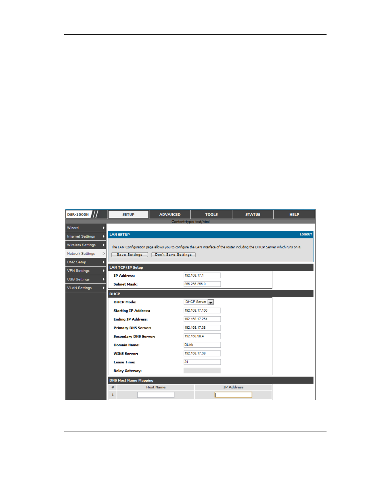
To configure LAN Connectivity, please follow the s teps below:
1. In the LAN Setup page, enter the following information for your router:
IP address (factory default: 192.168.10.1).
If you change the IP address and click Save Settings, the GUI will not res pond.
Open a new connection to the new IP addres s and log in again. Be s ure the LAN
host (the machine used to manage the router) has obtained IP address from newly
ass igned pool (o r has a static IP ad dres s in the ro u t e r’s LA N su b n e t ) before
accessing the router via changed IP addres s.
Subnet mask (factory default: 255.255.255.0).
2. In the DHCP section, select the DHCP mode:
No n e: t h e ro ut er’s DHCP s erv er is d is ab led fo r t h e LA N
DHCP Server. With this option the router assigns an IP address within the
specified range plus additional specified information to any LAN device
that reques ts DHCP s erved address es .
DHCP Relay: With this option enabled, DHCP clients on the LAN can
receive IP address leases and corres ponding information from a DHCP
server on a different subnet. Specify the Relay Gateway, and when LAN
clients make a DHCP request it will be pas sed along to the s erver
accessible via the Relay Gateway IP address .
If DHCP is being enabled, enter the following DHCP server parameters:
Starting and Ending IP Address es : Enter the first and last continuous
addresses in the IP address pool. Any new DHCP client joining the LAN is
ass igned an IP address in this range. The defau lt starting address is
192.168.10.2. The default ending address is 192.168.10.100. Thes e
addresses should be in the same IP addres s subn e t as th e r o u t e r’s LA N IP
address. You may wis h to save part of the subnet range for devices with
statically ass igned IP addres ses in the LAN.
Primary and Secondary DNS servers : If configured domain name sys tem
(DNS) servers are available on the LA N enter their IP addres ses here.
WINS Server (optional): Enter the IP addres s for the W INS server or, if
pres ent in you r network, the Windows NetBios server.
14
Page 17
Unified Services Router User Manual
Lease Time: Enter the time, in hours, for which IP addres ses are leased to
clients.
Relay Gateway: Enter the gateway address. This is the only configuration
parameter required in this s ection when DHCP Relay is selected as its
DHCP mode
3. In the DNS Host Name Mapping section:
Hos t Name: Provide a valid host name
IP address : Provide the IP address of the hos t n ame,
4. In the LAN proxy section:
Enable DNS Proxy: To enable the router to act as a proxy for all DNS
re q u es ts a n d co mmu n icat e with th e ISP’s DNS s ervers , c lick t h e checkb o x.
5. Click Save Settings to apply all changes.
Figure 1: Se tup page for LAN TCP/IP s ettings
15
Page 18

Unified Services Router User Manual
2.1.1 LAN DHCP Reserved IPs
Setup > Network Settings > LAN DHCP Reserved IPs
This router DHCP server can assign TCP/IP configurations to computers in the LAN
explicitly by adding client's network interface hardware address and the IP add ress to
be ass igned to that client in DHCP s erver's database. Whenever DHCP server receives
a request from client, hardware address of that client is compared with the hardware
address list present in the database, if an IP address is already assigned to that
computer or device in the database , the customized IP address is configured
otherwis e an IP address is ass igned to the client automatically from the DHCP pool.
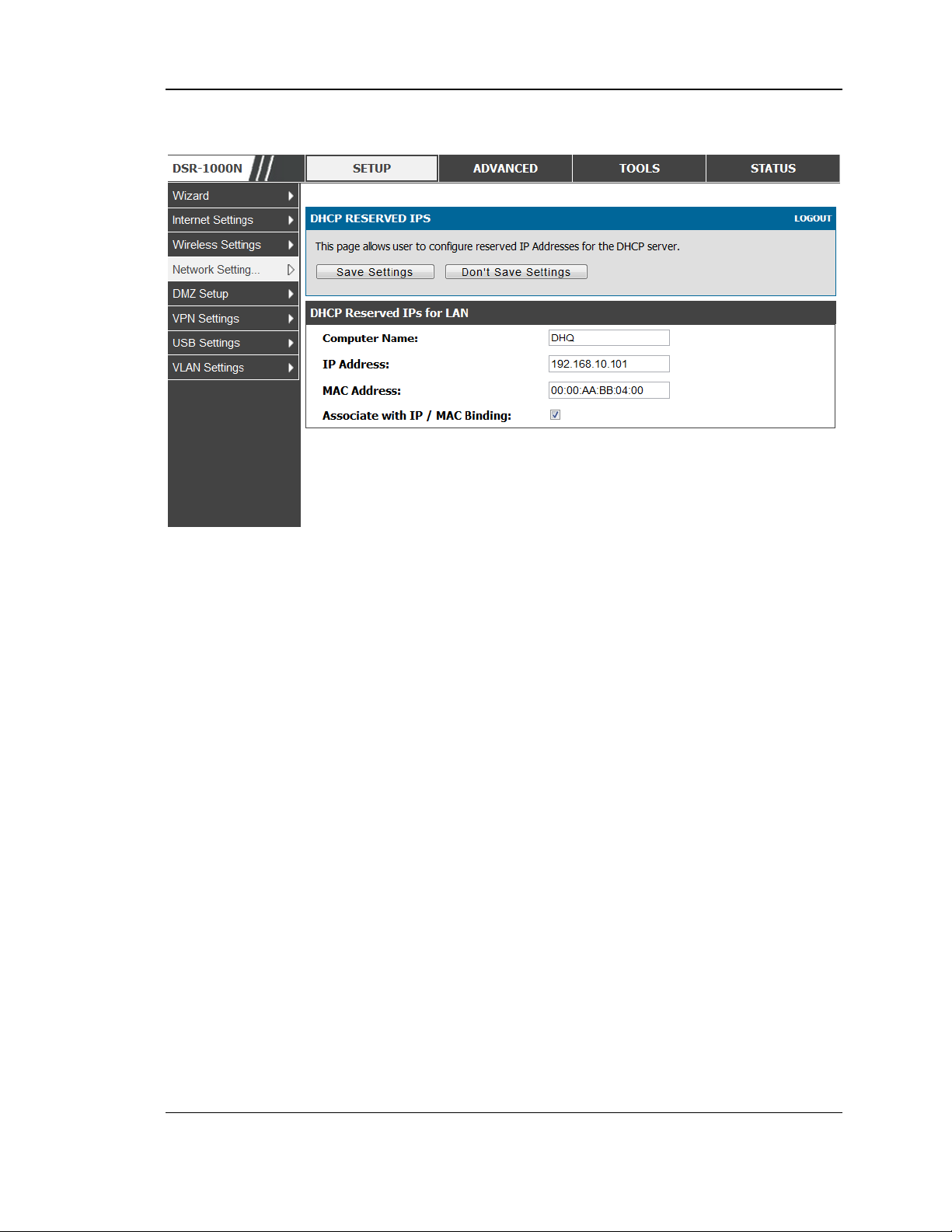
Computer Name: The user defined name for the LAN hos t.
IP Address es: The LAN IP addres s of a host that is res erved by the DHCP server.
MAC Address es: The MAC address that will be as signed the res erved IP address
when it is on the LAN.
As sociate with IP/MAC Binding: W hen the user enables this option the Computer
Name, IP and MAC addres ses are ass ociated with the IP/MAC binding.
The actions that can be taken on lis t of reserved IP address es are:
Select: Selects all the res erved IP address es in the list.
Edit: Opens the LAN DHCP Reserved IP Configuration page to edit the selected
binding rule.
Delete: Deletes the selected IP address reservation(s)
Add: Opens the LAN DHCP Reserved IP Configuration page to add a new binding
rule.
16
Page 19
Unified Services Router User Manual
Figure 2: LAN DHCP Reserved IPs
2.1.2 LAN DHCP Leased Clients
Setup > Network Settings > LAN DHCP Leased Clients
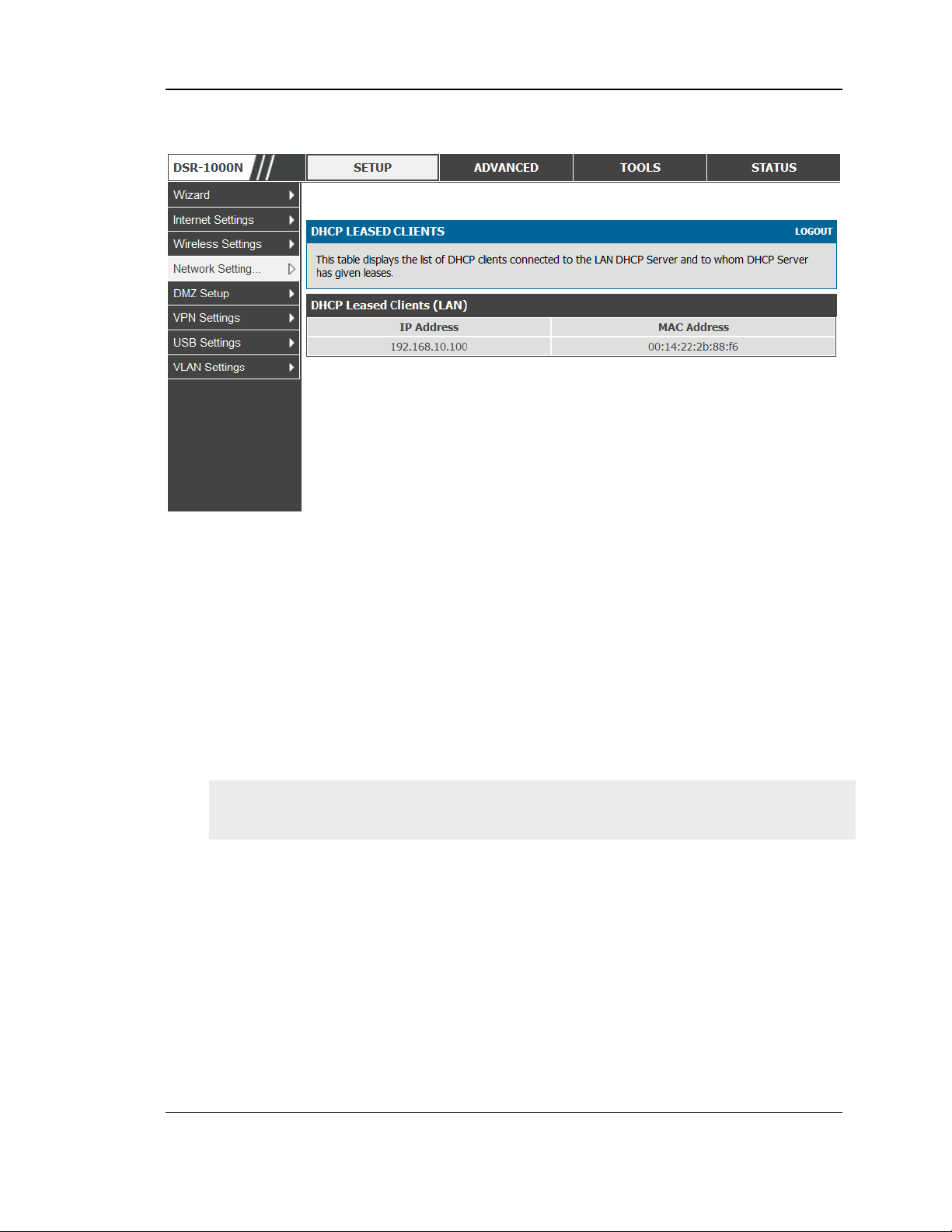
This page provides the lis t of clients connect to LAN DHCP server.
17
Page 20
Unified Services Router User Manual
Figure 3: LAN DHCP Lease d Clients
IP Addres ses : The LAN IP address of a host that matches the reserved IP list.
MAC Addres ses : The MAC address of a LAN hos t that has a configured IP address
res ervation.
2.1.3 LAN Configuration in an IPv6 Network
Advanced > IPv6 > IPv6 LAN > IPv6 LAN Config
(1) In IPv6 mode, the LAN DHCP server is enabled by default (similar to IPv4
mode). The DHCPv6 server will serve IPv6 addresses from configured address
pools with the IPv6 Prefix Length ass igned to the LAN.
IPv4 / IPv6 mode mus t be enabled in the Advanced > IPv6 > IP mode to enable
IPv6 configuration options.
LAN Settings
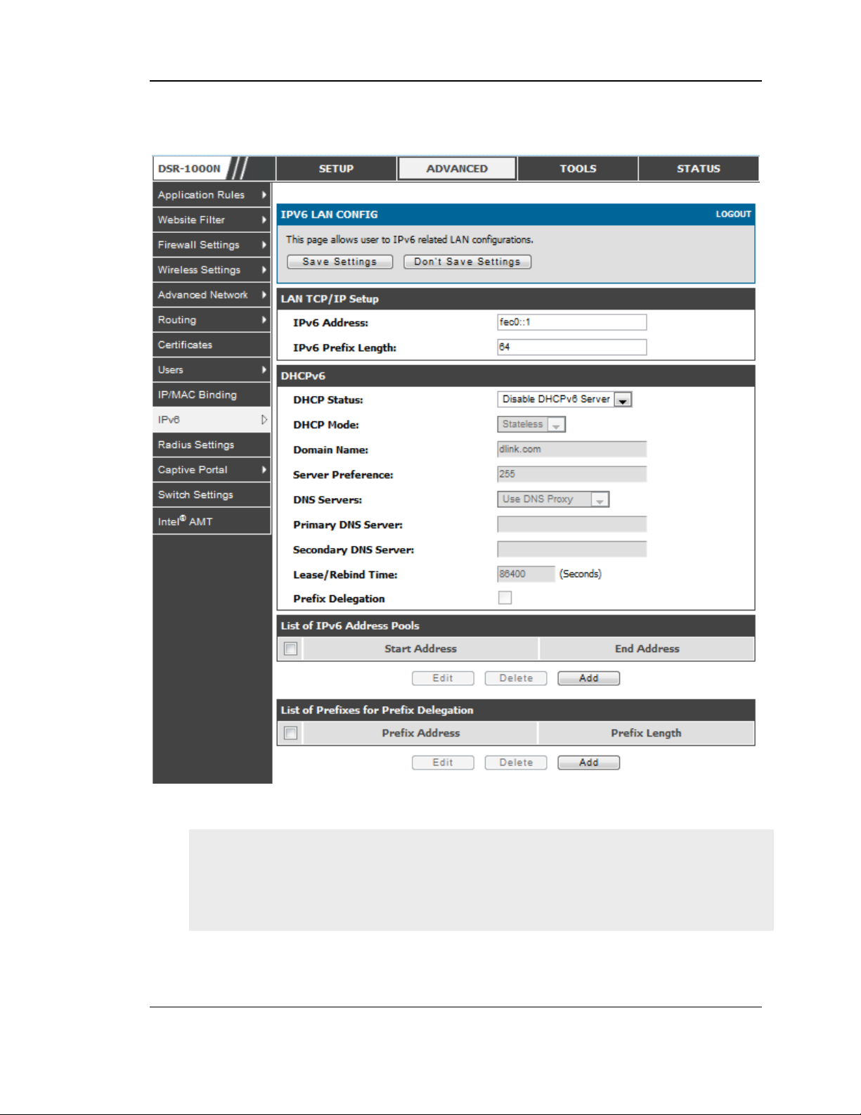
The default IPv6 LAN address for the router is fec0::1. You can change this 128 bit
IPv6 address based on your network requirements. The other field that defines the
LAN settings for the router is the prefix length. The IPv6 network (s ubnet) is
identified by the initial bits of the address called the prefix. By default this is 64
bits long. All hosts in the network have common initial bits for their IPv6 address ;
th e n umb e r o f c o mmo n in it ial b its in th e netwo rk’s add res s es is s e t b y t h e pre fix
length field.
18
Page 21
Unified Services Router User Manual
Figure 4: IPv6 LAN and DHCPv6 configuration
If you change the IP address and click Save Settings, the GUI will not res pond.
Open a new connection to the new IP addres s and log in again. Be s ure the LA N
host (the machine used to manage the router) has obtained IP address from newly
ass igned pool (or has a static IP address in th e rou t e r’s LA N sub n e t ) b e fore
accessing the router via changed IP addres s.
19
Page 22

Unified Services Router User Manual
As with an IPv4 LAN network, the router has a DHCPv6 server. If enabled , the
router as signs an IP address within the specified range plus additional specified
information to any LAN PC that reques ts DHCP served address es .
The followin g s ettings are us ed to configure the DHCPv6 server:
DHCP Mode: The IPv6 DHCP server is either stateless or stateful. If s tateless is
selected an external IPv6 DHCP s erver is not required as the IPv6 LAN hos ts
are auto-configured by this router. In this case the router advertis ement daemon
(RADVD) must be configured on this device and ICMPv6 router discovery
mess ages are used by the host for auto -configuration. There are no managed
addresses to serve the LAN nodes. If stateful is selected the IPv6 LAN hos t will
rely on an external DHCPv6 server to provide required configuration settings
The domain name o f the DHCPv6 server is an optional setting
Server Preference is used to indicate the pre ference level of this DHCP s erver.
DHCP advertise mess ages with the highes t server preference value to a LA N
host are preferred over other DHCP server advertise mess ages . The default is
255.
The DNS server details can be manually entered here (primary/s econdary
optio ns. An alternative is to allow the LAN DHCP client to receive the DNS
server details from the ISP directly. By selecting Us e DNS proxy, this router
acts as a proxy for all DNS requests and communicates wit h th e ISP ’s DNS
servers (a W AN configuration parameter).
Primary and Secondary DNS servers : If there is configured domain name
sys tem (DNS) s ervers available on the LAN enter the IP addresses here.
Lease/Rebind time sets the duration of the DHCPv6 leas e from this router to the
LAN client.
IPv6 Address Pools
This feature allows you to define the IPv6 delegation prefix for a range of IP
addresses to be s erved b y the gatewa y ’s DHCPv6 s e rver. Using a delegation prefix
you can automate the process of informing other networking equipment on the LAN
of DHCP information s pecific for the ass igned prefix.
Prefix Delegation
The followin g settings are used to configure the Prefix Delegation:
Prefix Delegation: Select this option to enable prefix delegation in DHCPv6
server. This option can be selected only in Stateless Address Auto
Configuration mode of DHCPv6 s erver.
20
Page 23

Unified Services Router User Manual
Prefix A ddres s: IPv6 prefix addres s in the DHCPv6 s erver prefix pool
Prefix Length: Length prefix address
2.1.4 Configuring IPv6 Router Advertisements
Router Advertis ements are analogous to IPv4 DHCP as signments for LAN clients, in
that the router will ass ign an IP address and s upporting network information to
devices that are configured to accept s uch details. Router Advertisement is required
in an IPv6 network is required for stateless auto configuration of the IPv6 LAN. By
configuring the Router Advertisement Daemon on this router, the DSR will lis ten on
the LAN for router s olicitations and respond to these LAN hosts with rout er
advis ements .
RADVD
Advanced > IPv6 > IPv6 LAN > Router Advertisement
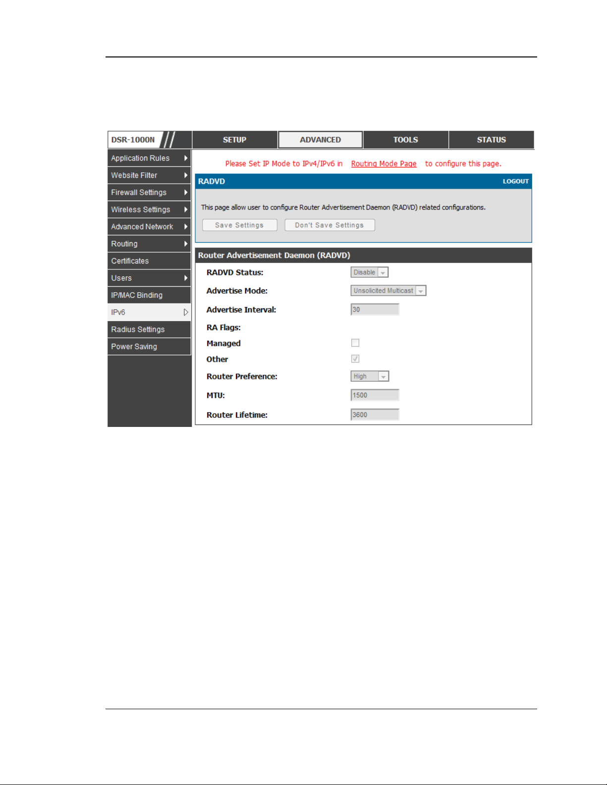
To support stateless IPv6 auto configuration on the LAN, set the RADVD s tatus to
Enable. The following settings are used to configure RADVD:
Advertise Mode: Select Unsolicited Multicast to send router advertis ements
(RA’s ) to all in te rfa c e s in t h e mu lt icas t gr o u p . To re s tric t RA’s to wellknown IPv6 address es on the LAN, and thereby reduce overall network
traffic, select Unicast only.
Advertise Interval: When advertisements are uns olicited multicast packets ,
this interval s ets the maximum time between advertisements from the
interface. The actual duration between advertis ements is a random value
between one third of this field and this field. The default is 30 s econds.
RA Flags: Th e rout er a d vertis eme n ts (RA ’s ) can be s en t wit h o n e o r b o th o f
these flags. Chose Managed to use the administered /stateful protocol for
address auto configuration. If the Other flag is selected the host uses
administered/stateful protocol for non-address auto configuration.
Router Preference: this low/medium/high parameter determines the
preference associated with the RADVD proces s of the router. This is us eful
if there are other RADVD enabled devices on the LAN as it helps avoid
conflicts for IPv6 clients.
MTU: The router advertisement will s et this maximum transmiss ion unit
(MTU) value for all nodes in the LAN that are auto configured by the router.
The default is 1500.
Router Lifetime: T h is v a lu e is p res ent in RA ’s a n d indic at es the u sefu lnes s
of this router as a default router for the interface. The default is 3600
21
Page 24
Unified Services Router User Manual
seconds. Upon expiration of this value, a new RADVD exchange must take
place between the host and this router.
Figure 5: Configuring the Route r Advertisement Daemon
Advertisement Prefixes
Advanced > IPv6 > IPv6 LAN > Advertisement Prefixes
The router advertisements configured with advertisement prefixes allow this router
to inform hos ts how to perform stateless address auto configuration. Router
advertisements contain a list of subnet prefixes that allow the router to determine
neighbours and whether the hos t is on the same link as the router.
The followin g prefix options are available for the router advertis ements :
IPv6 Prefix Type : To ensure hosts s upport IPv6 to IPv4 tunnel s elect the
6to4 prefix type. Selecting Global/Lo cal/ISATAP will allow the nodes to
support all other IPv6 routing options
SLA ID: The SLA ID (Site-Level Aggregation Identifier) is available when
6to4 Prefixes are s elected. This s h ou ld b e t h e in t e rfa c e ID o f the ro u t e r’s
LAN interface used for router advertis ements .
22
Page 25

Unified Services Router User Manual
IPv6 Prefix: When us ing Global/Local/ISA TAP prefixes, this field is us ed to
define the IPv6 network advertised by this router.
IPv6 Prefix Length: This value indicates the number contiguous , higher
order bits of the IPv6 address that define up the network portion of the
address. Typically this is 64.
Prefix Lifetime: This defines the duration (in seconds ) that the reques ting
node is allowed to us e the advertised prefix. It is analogous to DHCP lease
time in an IPv4 network.
Figure 6: IPv6 Adve rtise me nt Prefix settings
2.2 VLAN Configuration
The router supports virtual network isolation on the LAN with the use of VLANs.
LAN devices can be configured to communicate in a s ub network defined by VLAN
identifiers. LAN ports can be as signed unique VLAN IDs s o that traffic to and from
that phys ical port can be isolated from the general LA N. VLAN filtering is
particularly useful to limit broadcast packets of a device in a large network
VLAN support is disabled by default in the router. In the VLAN Configuration page,
enable VLAN support on the router and then proceed to the next section to define the
virtual network.
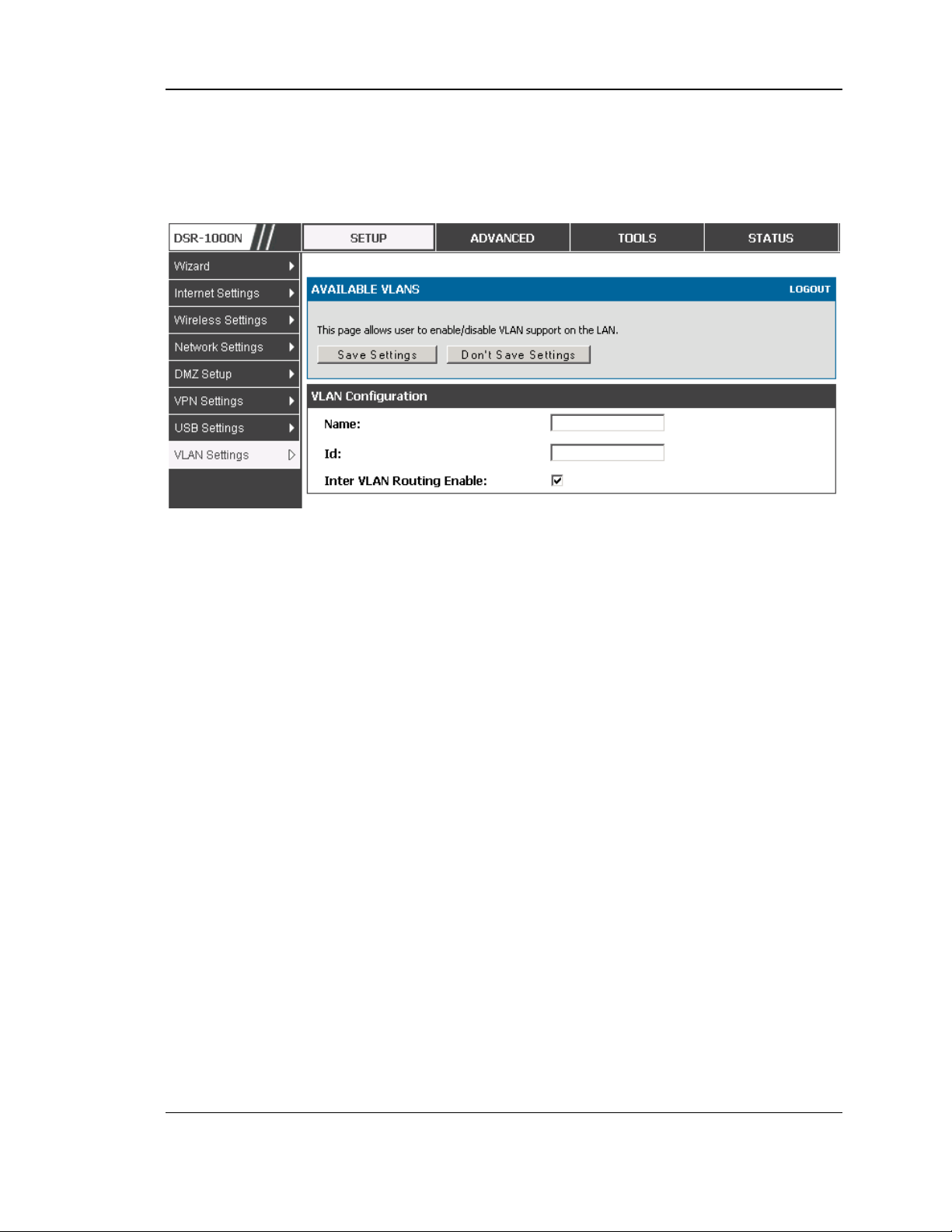
Setup > VLAN Settings > Available VLAN
The Available VLAN page shows a list of configured VLANs by name and VLAN ID.
A VLAN membership can be created by clicking the Add button below the Lis t of
Available VLANs .
A VLAN membership entry consists of a VLAN identifier and the numerical VLAN
ID which is as signed to the VLAN membership. The VLAN ID value can be any
23
Page 26
Unified Services Router User Manual
number from 2 to 4091. VLAN ID 1 is reserved for the default VLAN, which is us ed
for untagged frames received on the interface. By enabling Inter VLAN Routing, you
will allow traffic from LAN hos ts belonging to this VLAN ID to pas s through to other
configured VLAN IDs that have Inter VLAN Routing enabled.
Figure 7: Adding VLAN me mberships to the LAN
2.2.1 Associating VLANs to ports
In order to tag all traffic through a specific LAN port with a VLAN ID, you can
ass ociate a VLAN to a physical port.
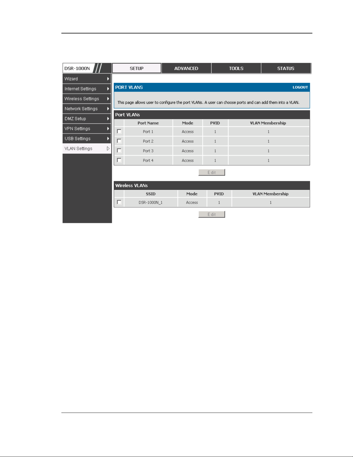
Setup > VLAN Settings > Port VLAN
VLAN membership properties for the LAN and wireles s LAN are lis ted on this page.
The VLAN Port table dis plays the port identifier, the mode setting for that port and
VLAN membership information. The configuration page is access ed by selecting
one of the four physical ports or a configured access point and clicking Edit.
The edit page offers the following configuration options:
Mode: The mode of this VLAN can be General, Acces s, or Trunk. The
default is acces s.
In General mode the port is a member of a us er s electable set of VLANs.
The port sends and receives data that is tagged or untagged with a VLAN
ID. If the data into the port is untagged, it is assigned the defined PVID. In
the configuration from Figure 4, Port 3 is a General port with PVID 3, s o
untagged data into Port 3 will be as signed PVID 3. A ll tagged data s ent out
of the port with the s ame PVID will be untagged. This is mode is typically
used with IP Phones that have dual Ethernet ports. Data coming from phone
to the switch port on the router will be tagged. Data pass ing through the
phone from a connect ed device will be untagged .
24
Page 27
Unified Services Router User Manual
Figure 8: Port VLAN list
In Access mode the port is a member of a s ingle VLAN (and only one). All
data going in to and out of the port is untagged. Traffic through a port in
access mode looks like any other Ethernet frame.
In Trunk mode the port is a member of a user selectable s et of VLANs. All
data going in to and out of the port is tagged. Untagged coming into the port
is not forwarded, except for the default VLAN with PVID=1, which is
untagged. Trunk ports multiplex traffic for multiple VLANs over the same
phys ical link.
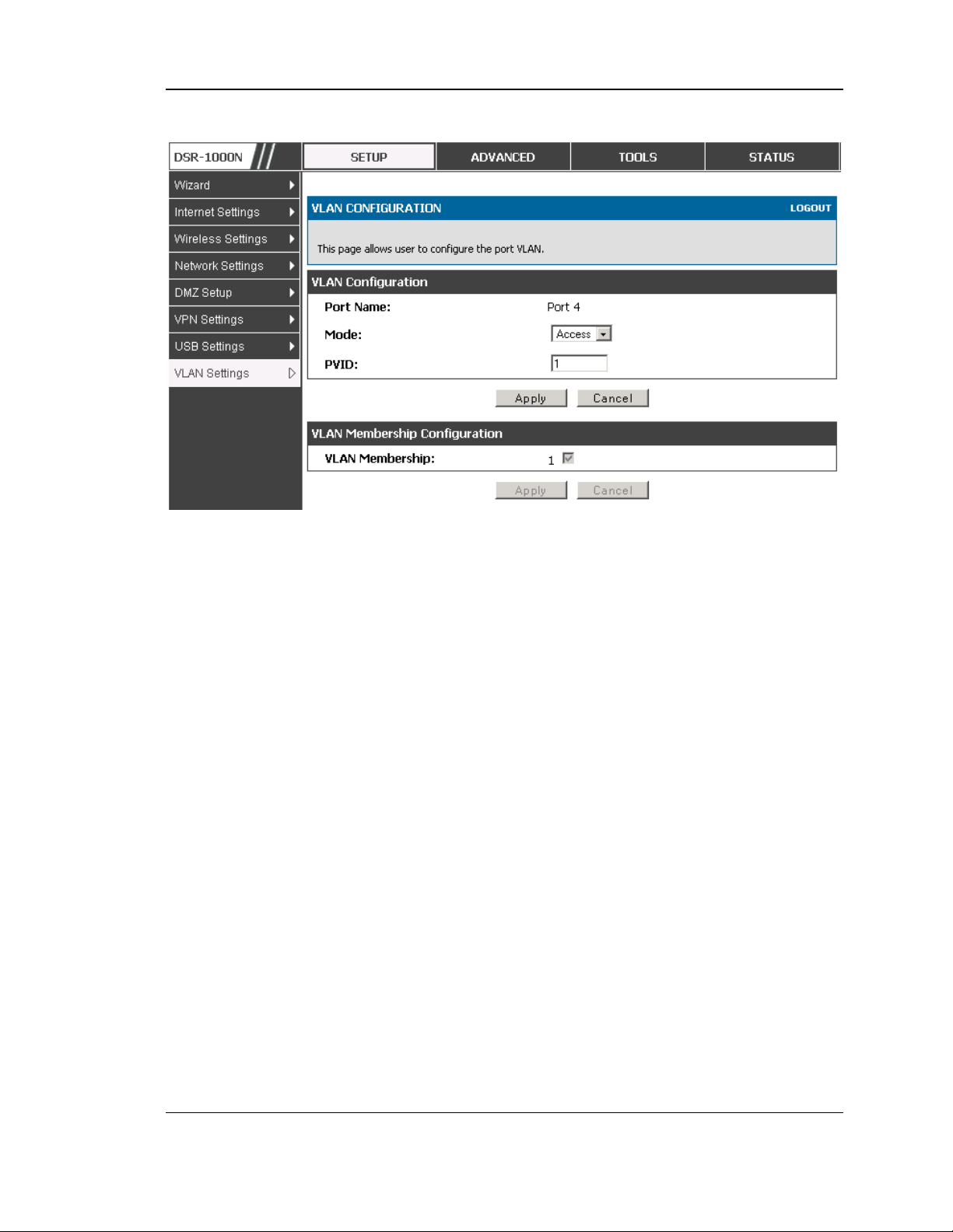
Select PVID for the port when the General mode is selected.
Configured VLAN members hips will be displayed on the VLAN
Members hip Configuration for the port. By selecting one more VLAN
members hip options for a General or Trunk port, traffic can be routed
between the selected VLAN members hip IDs
25
Page 28
Unified Services Router User Manual
Figure 9: Configuring VLAN membe rship for a port
2.2.2 Multiple VLAN Subnets
Setup > VLAN Settings > Multi VLAN Settings
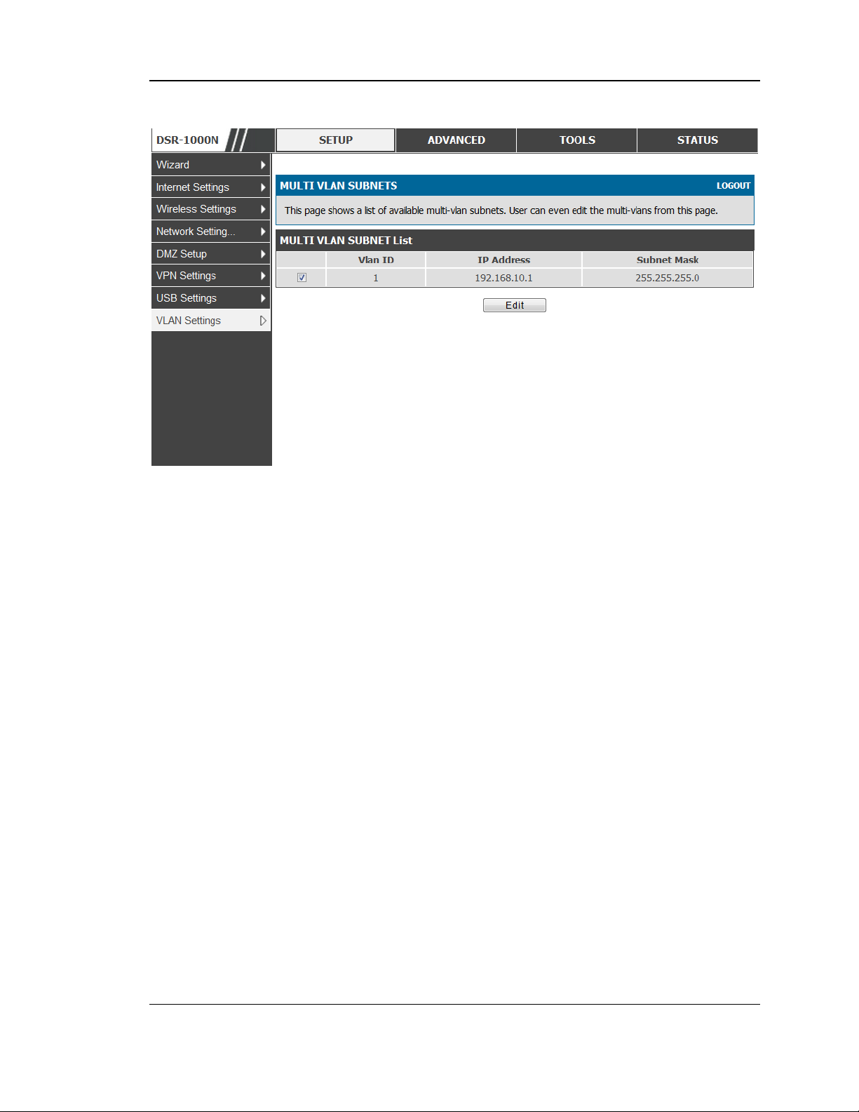
This page shows a list of available multi-VLAN s ubnets. Each configured VLAN ID
can map directly to a subnet within the LAN. Each LAN port can be ass igned a
unique IP address and a VLAN specific DHCP server can be configured to ass ign IP
address leases to devices on this VLAN.
VLAN ID: The PVID of the VLAN that will have all member devices be part of the
same subnet range.
IP Address : The IP address ass ociated with a port as signed this VLAN ID.
Subnet Mas k: Subnet Mask for the above IP A ddres s
26
Page 29
Unified Services Router User Manual
Figure 10: Multiple VLAN Subnets
2.2.3 VLAN configuration
Setup > VLAN Settings > VLANconfiguration
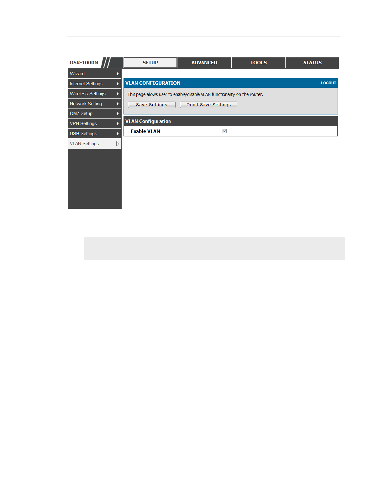
This page allows enabling or disabling the VLAN function on the router. Virtual
LANs can be created in this router to provide segmentation capabilities for firewall
rules and VPN policies. The LAN network is cons idered the default VLAN. Check
the Enable VLAN box to add VLAN functionality to the LAN.
27
Page 30
Unified Services Router User Manual
Figure 11: VLAN Configuration
2.3 Configurable Port: DMZ Setup
DSR-150/150N/250/ 250N does not have a configurable port – there is no DMZ
support.
This router supports one of the physical ports to be configured as a s econdary WAN
Ethernet port or a dedicated DMZ port. A DMZ is a s ub network that is open to the
public but behind the firewall. The DMZ adds an additional layer of security to the
LAN, as specific services/ports t hat are exposed to the internet on the DMZ do not
have to be exposed on the LAN. It is recommended that hosts that mus t be exposed to
the internet (such as web or email s ervers) be placed in the DMZ network. Firewall
rules can be allowed to permit access specific services /p orts to the DMZ from both
the LAN or WAN. In the event of an attack to any of the DMZ nodes, the LAN is not
necess arily vulnerable as well.
Setup > DMZ Setup > DMZ Setup Configuration
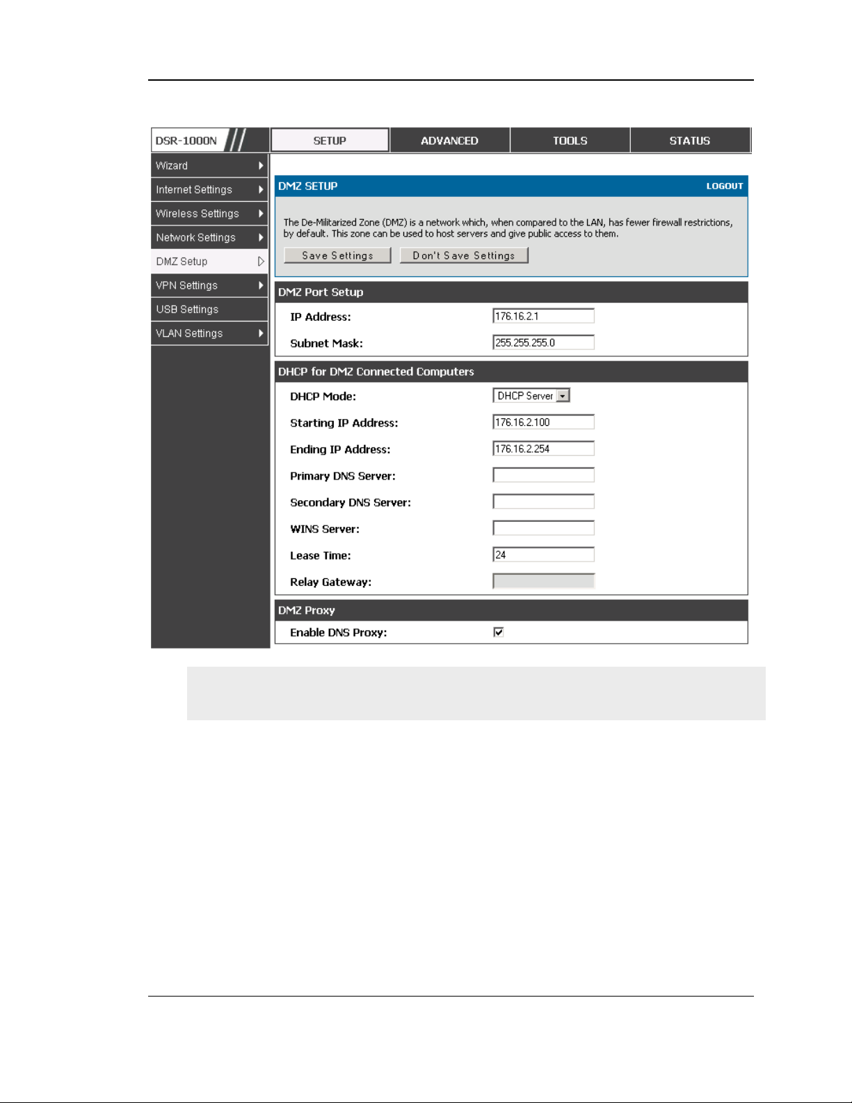
DMZ configuration is identical to the LAN configuration. There are no restrictions on
the IP addres s or subnet assigned to the DMZ port, other than the fact that it cannot
be identical to the IP address given to the LAN interface of this gateway.
28
Page 31
Unified Services Router User Manual
Figure 12: DMZ configuratio n
In order t o co n fig u re a DMZ p o rt, th e ro u t e r’s co n fig u rable po rt mu s t b e s e t to
DMZ in the Setup > Internet Settings > Configurable Port page.
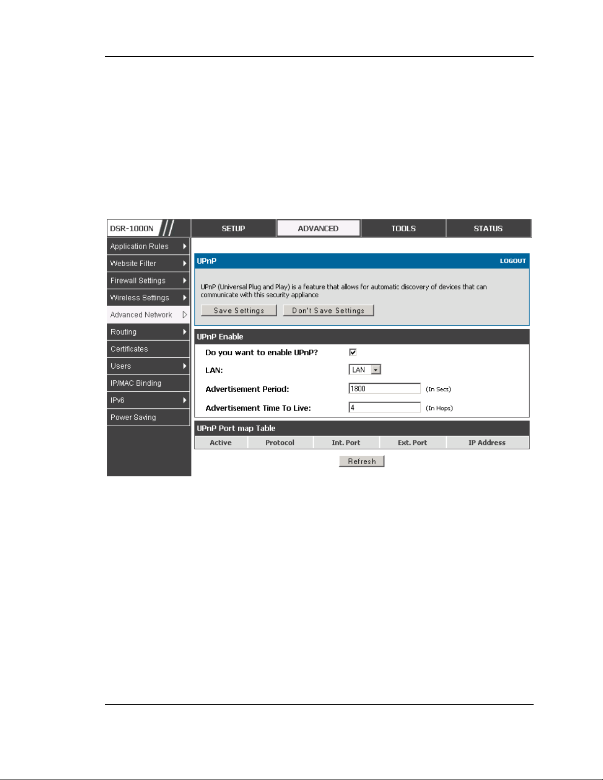
2.4 Universal Plug and Play (UPnP)
Advanced > Advanced Network > UPnP
Univers al Plug and Play (UPnP) is a feature that allows the router to discovery
devices on the network that can communicate with the router and allow for auto
configuration. If a network device is detected by UPnP, the router can open internal
or external ports for the traffic protocol required by that network device.
Once UPnP is enabled, you can configure the router to detect UPnP-supporting
devices on the LAN (or a configured VLAN). If disabled, the router will not allow for
automatic device configuration.
Configure the following settings to use UPnP:
29
Page 32
Unified Services Router User Manual
Advertis ement Period: This is the frequency that the router broadcas ts UPnP
information over the network. A large value will minimize network traffic but
cause delays in identifying new UPnP devices to the network.
Advertisement Time to Live: This is expres sed in hops for each UPnP packet. This
is the number of s teps a packet is allowed to propagate before being discarded.
Small values will limit the UPnP broadcas t range. A default of 4 is typical for
networks with few switches .
Figure 13: UPnP Configuratio n
UPnP Port map Table
The UPnP Port map Table h a s t h e d e t ails o f UPn P dev ices t hat re s pond to th e ro u te r’s
advertisements . The following information is dis played for each detected device:
Active: A yes/no indicating whether the port of the UPnP device that established a
connectio n is currently active
Protocol: The network protocol (i.e. HTTP, FTP, etc.) used by the DSR
Int. Port (Internal Port): The internal ports opened by UPnP (if any)
Ext. Port (External Port): The external ports opened by UPnP (if any)
IP A ddres s: The IP address of the UPnP device detected by this router
Click Refresh to refresh the portmap table and search for any new UPnP devices.
30
Page 33

Unified Services Router User Manual
2.5 Captive Portal
DSR-150/150N/250/ 250N does not have support for the Captive Portal feature.
LAN users can gain internet acces s via web portal authentication with the DSR.
Als o referred to as Run-Time Authentication, a Captive Portal is ideal for a web
café scenario where users initiate HTTP connection requests for web access but are
not interes ted in accessing any LAN s ervices . Firewall policies underneath will
define which us ers require authentication for HTTP access, and when a matching
user request is made the DSR will intercept the request and prompt for a username /
pass word. The login credentials are compared agains t the RunTimeAuth us ers in
user database prior to granting HTTP access .
Captive Portal is available for LAN us ers only and not for DMZ hosts .
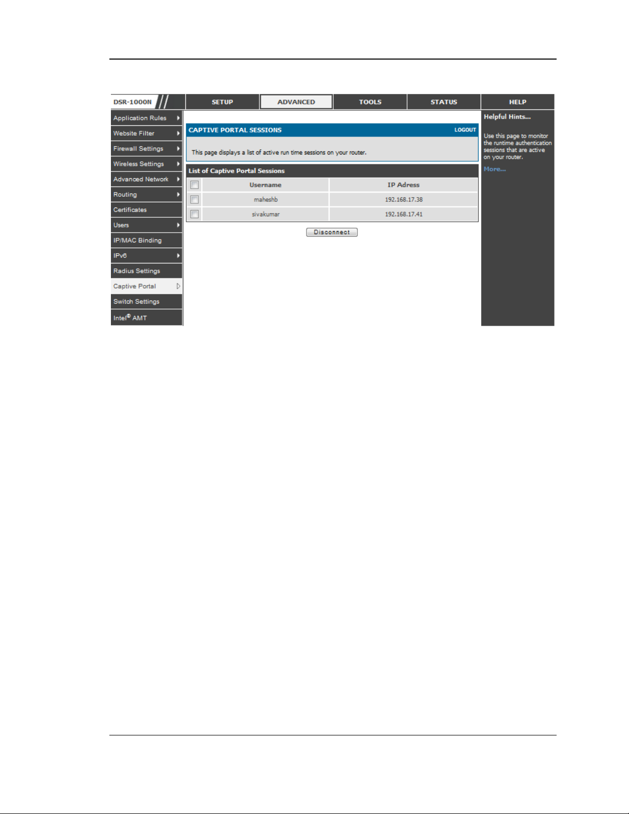
Advanced > Captive Portal >Captive Portal Sessions
The Active Runtime internet sessions through t h e ro ut e r ’s fire wall are lis ted in t h e
below table. These users are present in the local or external us er database and have
had their login credentials approved for internet access. A ‘Dis co nn ec t ’ b ut t on
allows the DSR admin to selectively drop an authenticated user.
31
Page 34
Unified Services Router User Manual
Figure 14: Active Runtime sessions
2.6 Captive portal setup
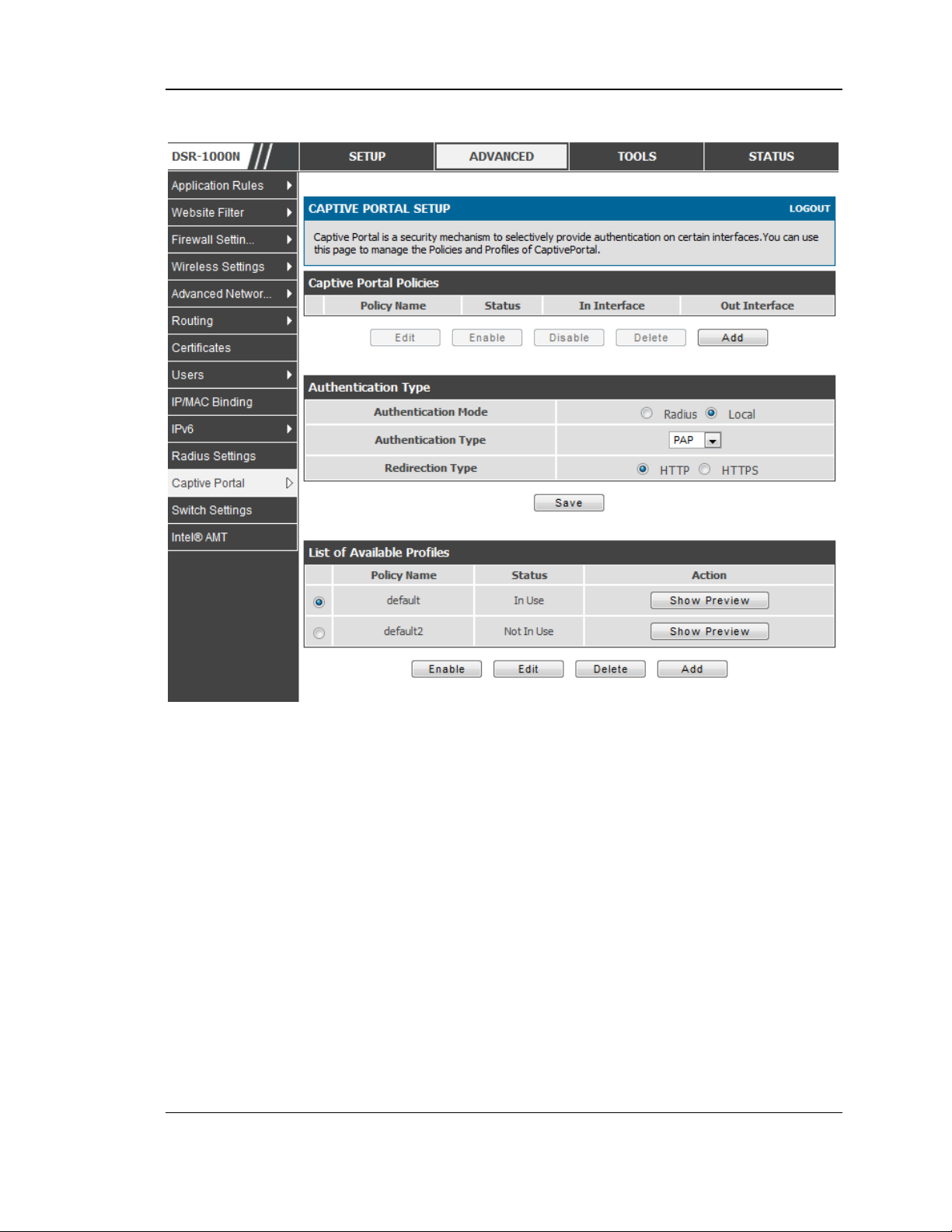
Advanced > Captive Portal >Captive Portal Setup
Captive Portal is a security mechanism to selectively provide authentication on
certain interfaces. This page allows to manage the Policies and Profiles of
CaptivePortal.
32
Page 35
Unified Services Router User Manual
Figure 15: Captive Portal Setup
Captive Portal Policies: The List of Available CaptivePortal Policies are shown in
this table.
Authentication Type : This allows in choos ing the authentication mode, type and
redirection type.
List of Available Profiles : Any one of these profiles can be used for Captive Portal
Login page while enabling Captive Portal.
33
Page 36
Unified Services Router User Manual
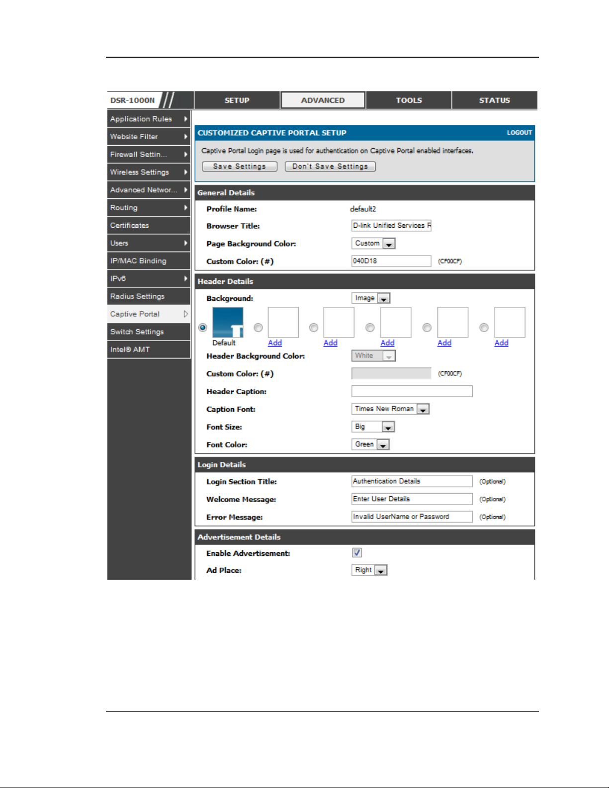
Figure 16: Customized Captive Portal Setup
Click “ A dd ” in t h e Ca p t ive Po rta l s etu p p a g e to allo w d efin in g cus tomized captive
portal login page information (Page Background Color, Header Details , Header
Caption, Login Section Details, Advertis ement Details, Footer Details and Captive
Portal Header Image).
34
Page 37
Unified Services Router User Manual
Chapter 3. Connecting to the Internet:
WAN Setup
This router has two W AN ports that can be us ed to es tablish a connection to the
internet. The following ISP connection types are supported: DHCP, Static, PPPoE,
PPTP, L2TP, 3G Internet (via USB modem).
It is as sumed that you have arranged for internet service with your Internet Service
Provider (ISP). Please contact your ISP or network administrato r for the configuration
information that will be required to s etup the router.
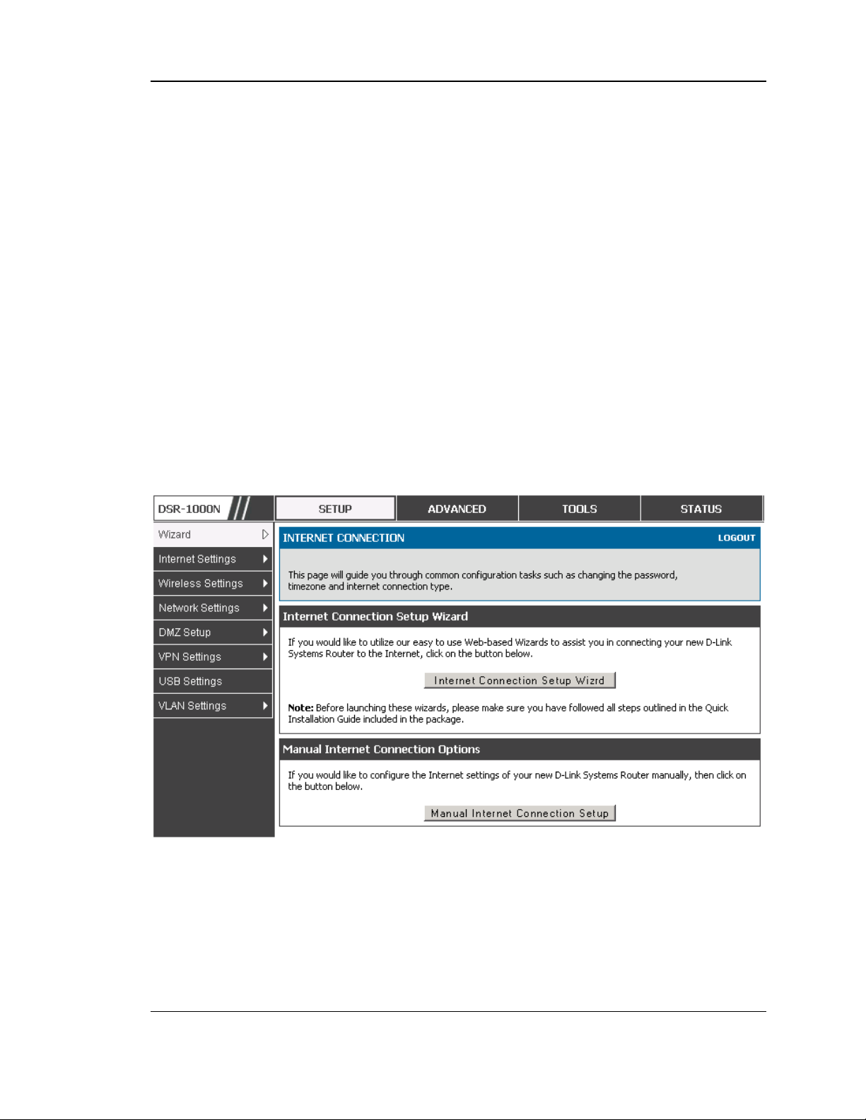
3.1 Internet Setup Wizard
Setup > Wizard > Internet
The Internet Connection Setup Wizard is available for users new to networking. By
going through a few straightforward configuration pages you can take the information
provided by your ISP to get your WAN connection up and enable internet acces s for
your network.
Figure 17: Inte rnet Connection Setup Wizard
You can s tart using the Wizard by logging in with the administrator pass word for the
router. Once authenticated set the time zone that you are located in, and then choos e
the type of ISP connection type: DHCP, Static, PPPoE, PPTP, L2TP. Depending on
the connection type a us ername/password may be required to register this router with
the ISP. In mos t cas es the default settings can be used if the ISP did not specify that
parameter. The las t step in the Wizard is to click the Connect button, which confirms
the settings by establishing a link with the ISP. Once connected, you can move on and
configure other features in this router.
35
Page 38

Unified Services Router User Manual
3G Internet acces s with a USB modem is supported on WAN3. The Internet
Connection Setup Wizard as sis ts with the primary WAN port (WA N1)
configuration only.
3.2 WAN Configuration
Setup > Internet Settings > WAN1 Setup
You mus t either allow the router to detect WA N connection type automatically or
configure manually the following basic settings to enable Internet connectivity:
ISP Connection type: Based on the ISP you have selected for the primary WAN
link for this router, choose Static IP addres s, DHCP client, Point-to -Point
Tunneling Protocol (PPTP), Point -to-Point Protocol over Ethernet (PPPoE), Layer
2 Tunneling Protocol (L2TP). Required fields for the selected ISP type become
highlighted. Enter the following information as needed and as provided by your
ISP:
PPPoE Profile Name. This menu lists configured PPPoE profiles , particularly
useful when configuring multiple PPPoE connections (i.e. for Japan ISPs that
have multiple PPPoE support).
ISP login information. This is required for PPTP and L2TP ISPs.
User Name
Pass word
Secret (required for L2TP only)
MPPE Encryption: For PPTP links, your ISP may require you to enable Microso ft
Point-to -Point Encryption (MPPE).
Split Tunnel (s upported for PPTP and L2TP connection). This setting allows your
LAN hos ts to access internet sites over this WAN link while s till permitting VPN
traffic to be directed to a VPN configured on this WAN port.
If s p lit tun n e l is en abled, DSR wo n ’t expe c t a d e fa u lt rou t e from t h e IS P s erver. In
such case, user has to take care of routing manually by configuring the routing from
Static Routing page.
Connectivity Type: To keep the connection always on, click Keep Connected. To
log out after the connection is idle for a period of time (us eful if your ISP costs are
based on logon times), click Idle Timeout and enter the time, in minutes , to wait
before disconnecting in the Idle Time field.
36
Page 39

Unified Services Router User Manual
My IP Address : Enter the IP address ass igned to you by the ISP.
Server IP Address : Enter the IP address of the PPTP or L2TP server.
DSR-150/150N/250/ 250N d o e s n’t have a d u a l W A N s uppo rt.
3.2.1 WAN Port IP address
Your ISP assigns you an IP address that is either dynamic (newly generated each
time you log in) or static (permanent). The IP Address Source option allows you to
define whether the address is statically provided by the ISP or s hould be received
dynamically at each login. If s tatic, enter your IP address, IPv4 subnet mask, and the
ISP g a t e way’s IP add res s. PPTP and L2TP ISPs also can provide a static IP address
and s ubnet to configure, however the default is to receive that information
dynamically from the ISP.
3.2.2 WAN DNS Servers
The IP Address es of WAN Domain Name Servers (DNS) are typically provided
dynamically from the ISP but in some cases you can define the static IP addresses of
the DNS servers. DNS servers map Internet domain names (example:
www.google.com) to IP addres ses. Click to indicate whether to get DNS s erver
addresses automatically from your ISP or to use ISP -specified addres ses. If its
latter, enter addres ses for the primary and secondary DNS servers . To avoid
connectiv ity problems , ensure that you enter the address es correctly.
3.2.3 DHCP WAN
For DHCP client connections, you can choose the MAC address of the router to
register with the ISP. In s o me cas e s y o u may need t o clo n e t h e LA N h o s t’ s M A C
address if the ISP is registered with that LAN hos t.
37
Page 40
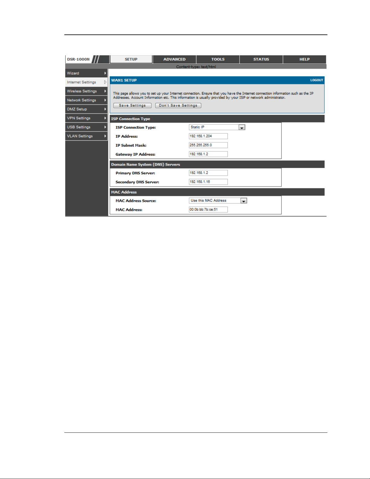
Unified Services Router User Manual
Figure 18: Manual WAN configuration
3.2.4 PPPoE
Setup > Internet Settings
The PPPoE ISP settings are defined on the WAN Configuration page. There are two
types of PPPoE IS P’s s upported by the DSR: the standard us ername/pas sword
PPPoE and Japan Multiple PPPoE.
38
Page 41
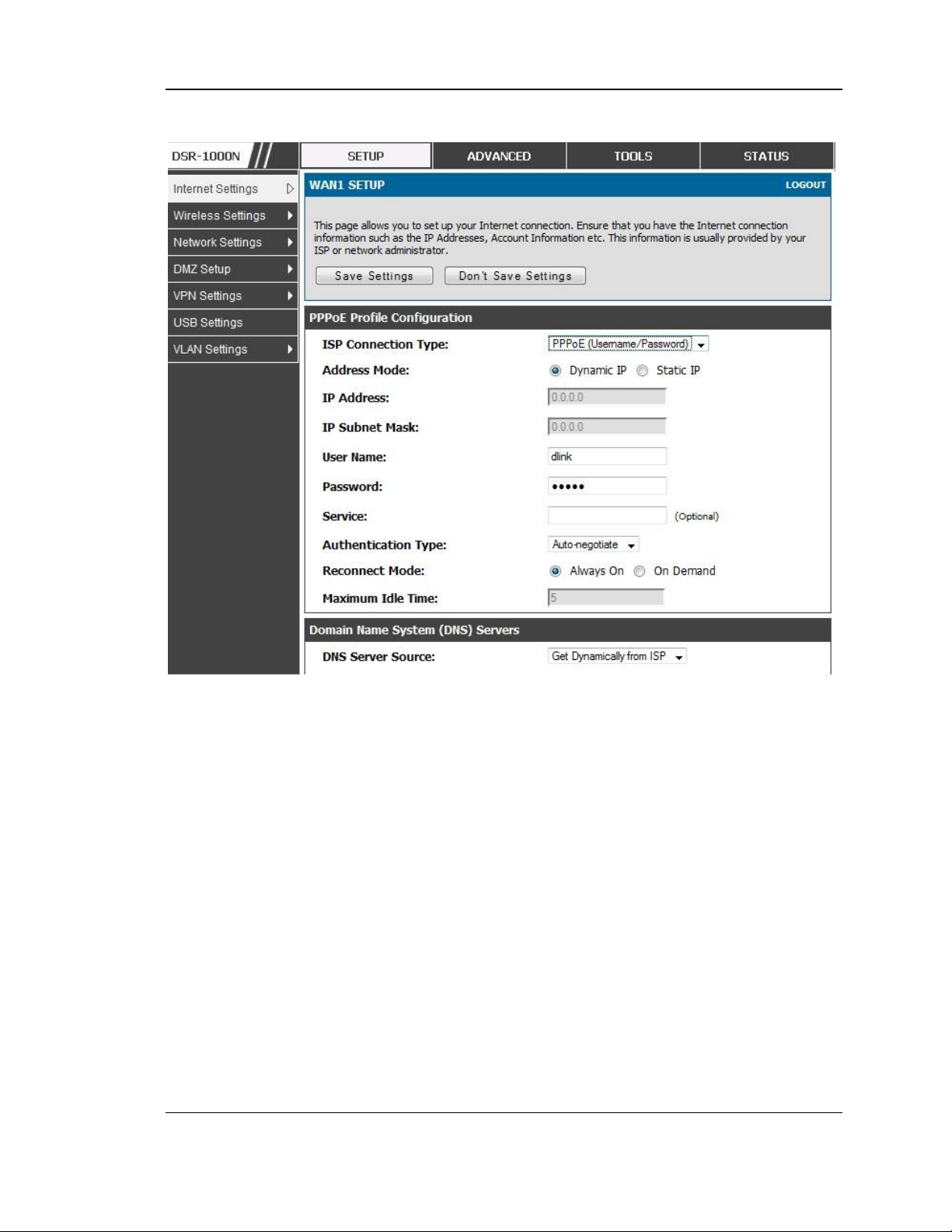
Unified Services Router User Manual
Figure 19: PPPoE configuratio n for standard ISPs
Mo s t PPP o E IS P’s u s e a s ingle co nt r ol an d d a ta co nnect ion , a n d require u s ername /
pass word credentials to login and authenticate the DSR with the ISP. The ISP
con n e c t io n ty p e fo r th is cas e is “ PPPoE (Us e rname/ Pas s word )”. Th e GUI will
prompt you for authentication, service, and connection settings in order to establish
the PPPoE link.
For s ome ISP ’s , mo s t po p ular in Jap a n , t h e u s e of “ Japanese M u ltip le PPPoE” is
required in order to establish concurrent primary and secondary PPPoE connections
between the DSR and the ISP. The Primary connection is used for the bulk of data
and internet traffic and the Secondary PPPoE connection carries ISP specific (i.e.
control) traffic between the DSR and the ISP.
39
Page 42
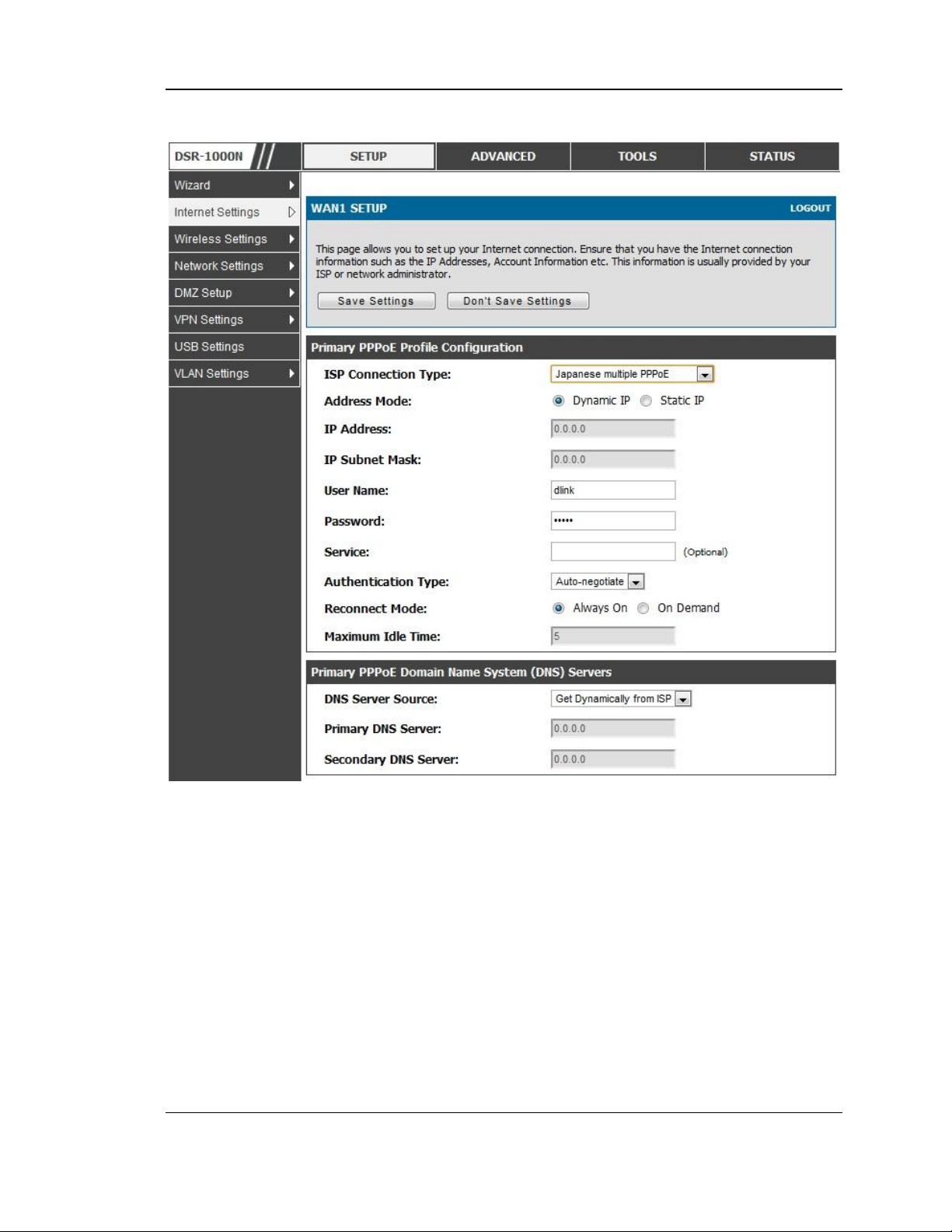
Unified Services Router User Manual
Figure 20: WAN configuratio n for Japanese Multiple PPPoE (part 1)
There are a few key elements of a multiple PPPoE connection:
Primary and secondary connections are concurrent
Each session has a DNS server source for domain name lookup, this can be assigned by
the ISP or configured through the GUI
The DSR acts as a DNS proxy for LAN users
Only HTTP reques ts that specific a lly id e n t ify the sec ond ary conne c tio n’s d o main n a me
(for example *.flets) will use the secondary profile to acces s the content available
through this s econdary PPPoE terminal. All other HTTP / HTTPS requests go through
the primary PPPoE connection.
40
Page 43
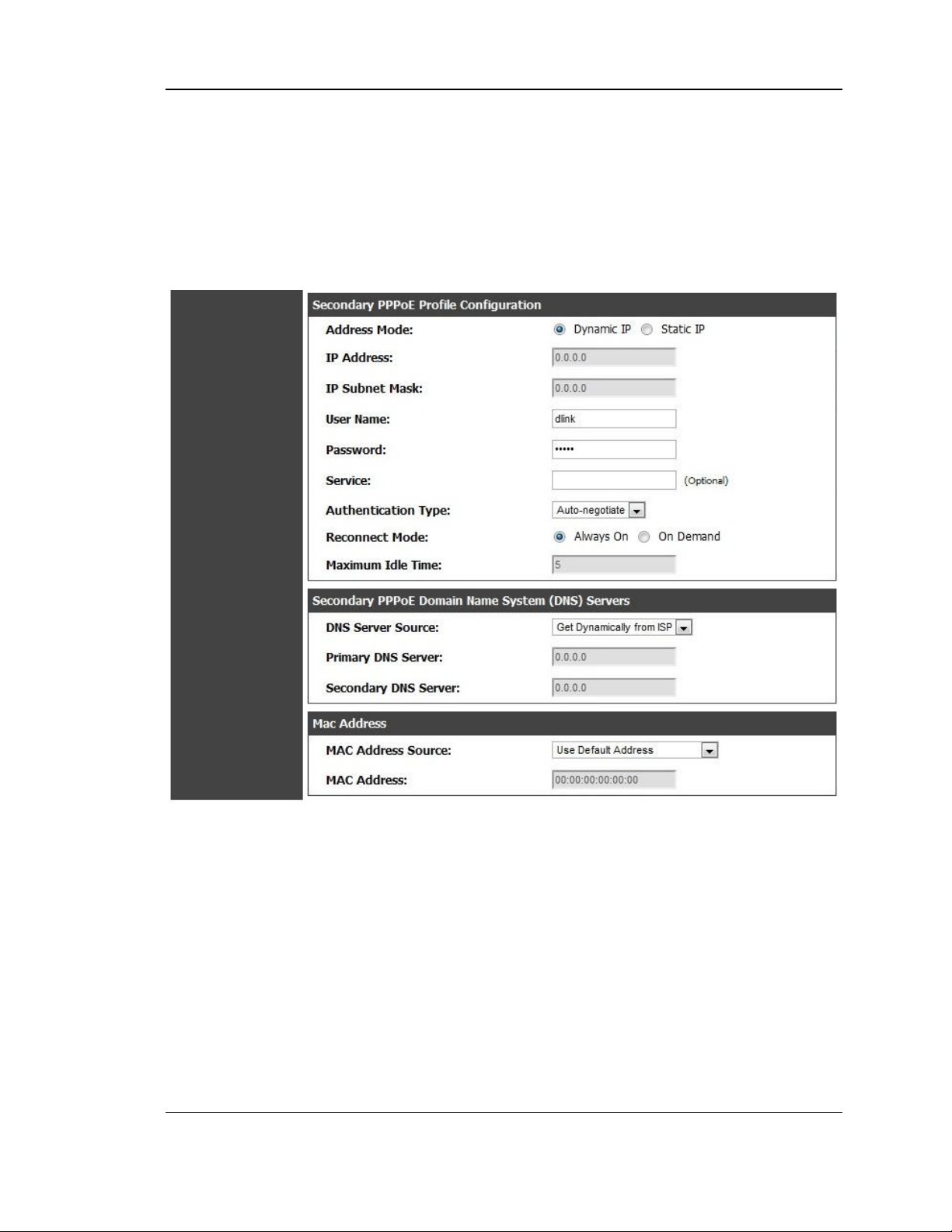
Unified Services Router User Manual
When Japanese multiple PPPoE is configured and secondary connection is up, some predefined
routes are added on that interface. These routes are needed to access the internal domain of the
ISP where he hos ts various services . Thes e routes can even be configured through the static
routing page as well.
Figure 21: WAN configuratio n for Multiple PPPoE (part 2)
3.2.5 Russia L2TP and PPTP WAN
For Russia L2TP WAN connections , you can choose the addres s mode of the
connectio n to get an IP addres s from the ISP or configure a static IP address
provided by the ISP. For DHCP client connections , you can choose the MAC
address of the router to register with the ISP. In some cases you may need to clone
th e LAN h o s t’s M A C a d d res s if t h e ISP is re g is t e r ed with that LAN host.
41
Page 44
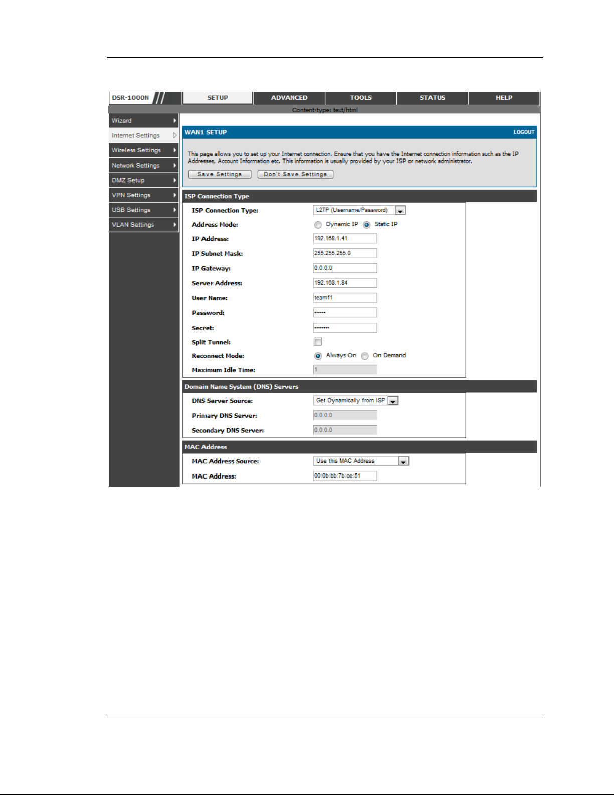
Unified Services Router User Manual
Figure 22: Russia L2TP ISP configuratio n
3.2.6 Russia Dual Access PPPoE
For Russ ia dual access PPPoE connections, you can choose the addres s mode of the
connectio n to get an IP address from the ISP or configure a s tatic IP address
provided by the ISP.
42
Page 45
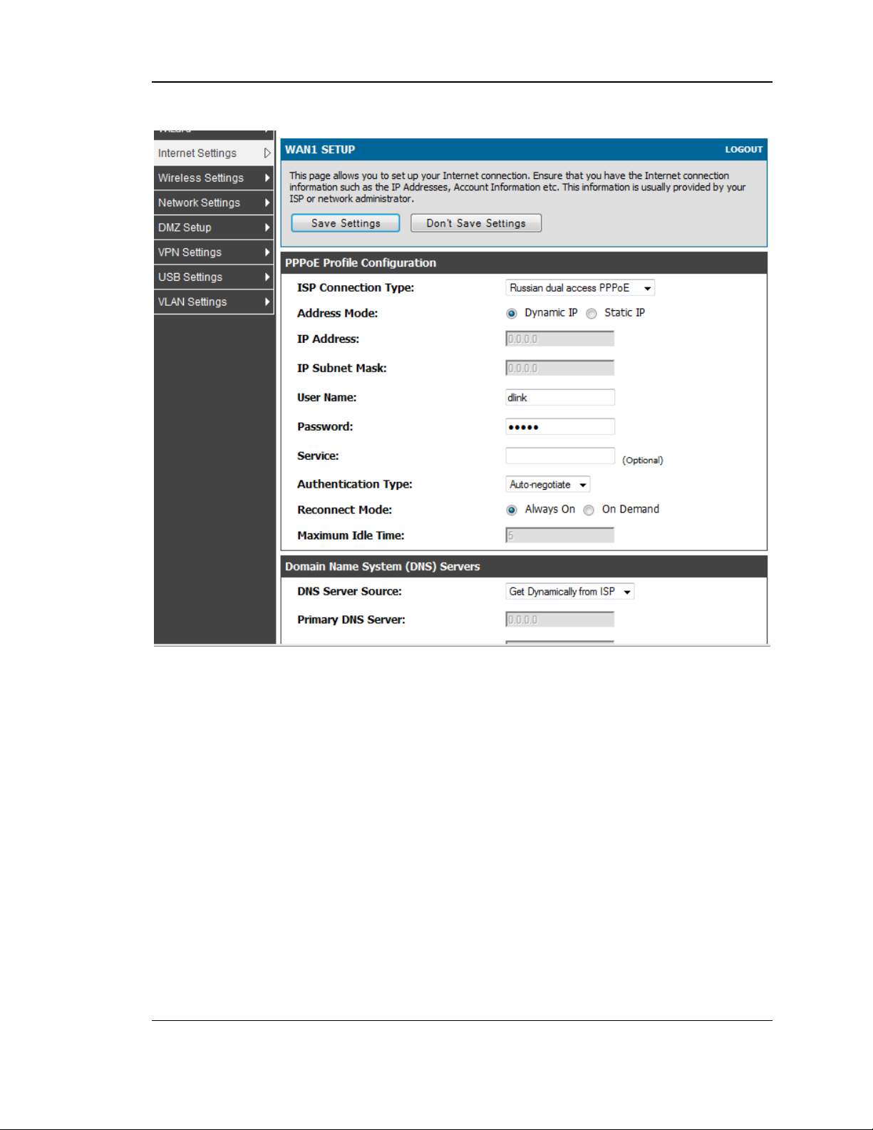
Unified Services Router User Manual
Figure 23: Russia Dual access PPPoE configuratio n
3.2.7 WAN Configuration in an IPv6 Network
Advanced > IPv6 > IPv6 WAN1 Config
For IPv6 W AN connections , this router can have a static IPv6 address or receive
connection information when configured as a DHCPv6 client. In the case where the
ISP as signs you a fixed address to access the internet, the static configuration
settings must be completed. In addition to the IPv6 address as signed to your router,
the IPv6 prefix length defined by the ISP is needed. The default IPv6 Gateway
address is the server at the ISP that this router will connect to for acces sing the
internet. The primary and s econdary DNS s ervers on the ISP’s IP v 6 n e t work a re
used for res olving internet addresses, and these are provided along with the s tatic IP
address and prefix length from the ISP.
When the ISP allows you to obtain the WAN IP settings via DHCP, you need to
provide details for the DHCPv6 client configuration. The DHCPv6 client on the
gateway can be either stateless or stateful. If a stateful client is s elected the gateway
will connect t o the ISP’s DHCPv 6 s erver fo r a le a s ed add res s . For stateless DHCP
43
Page 46
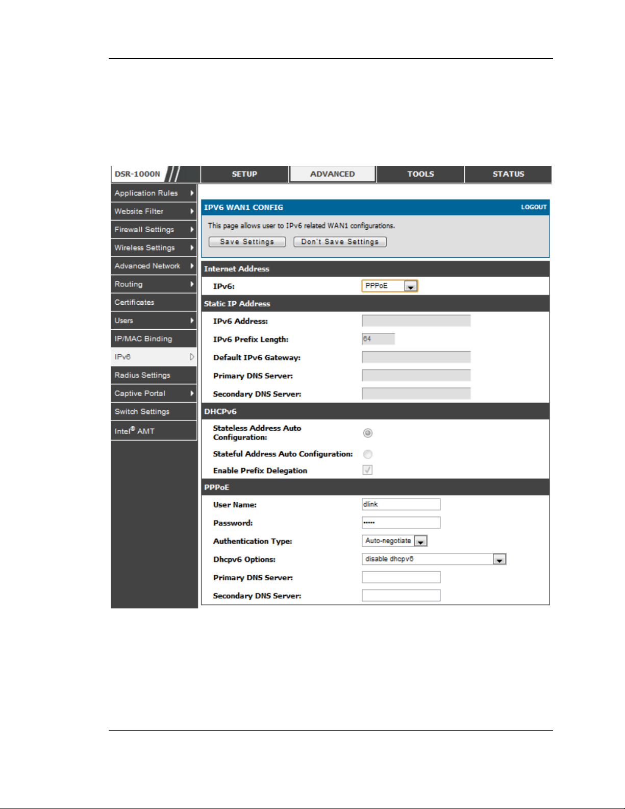
Unified Services Router User Manual
there need not be a DHCPv6 server available at the ISP, rather ICMPv6 dis cover
mess ages will originate from this gateway and will be us ed for auto configuration. A
third option to specify the IP address and prefix length of a preferred DHCPv6
server is available as well.
Figure 24: IPv6 WAN Setup page
Prefix Delegation: Select this option to request router advertisement prefix from any
available DHCPv6 s ervers available on the ISP, the obtained prefix is updated to the
advertised prefixes on the LAN side. This option can be selected only in Statesless
Address Auto Configuration mode of DHCPv6 Client.
When IPv6 is PPPoE type, the following PPPoE fields are enable d.
Us ername: Enter the username required to log in to the ISP.
44
Page 47

Unified Services Router User Manual
Pas sword: Enter the pas sword required to login to the ISP.
Authentication Type: The type of Authentication in use by the profile: Auto-
Negotiate/PAP/CHAP/MS-CHAP/MS-CHAPv2.
Dhcpv6 Options : The mode of Dhcpv6 client that will start in this mode:
dis able dhcpv6/stateless dhcpv6/stateful dhcpv6/stateless dhcpv6 with prefix
delegation.
Primary DNS Server: Enter a valid primary DNS Server IP Address .
Secondary DNS Server: Enter a valid s econdary DNS Server IP Address.
Click Save Settings to save your changes .
3.2.8 Checking WAN Status
Setup > Internet Settings > WAN1 Status
The status and summary of configured settings for both WAN1, WAN2 and WAN3
are available on the WAN Status page. You can view the following key connection
status information for each WAN port:
Connection time: The connection uptime
Connection type: Dynamic IP or Static IP
Connection state: This is whether the WAN is connected or disconnected to
an ISP. The Link State is whether the physical WAN connection in place;
the Link State can be UP (i.e. cable ins erted) while the WAN Connection
State is down.
IP address / subnet mask: IP Address ass igned
Gateway IP address : WAN Gateway Address
45
Page 48
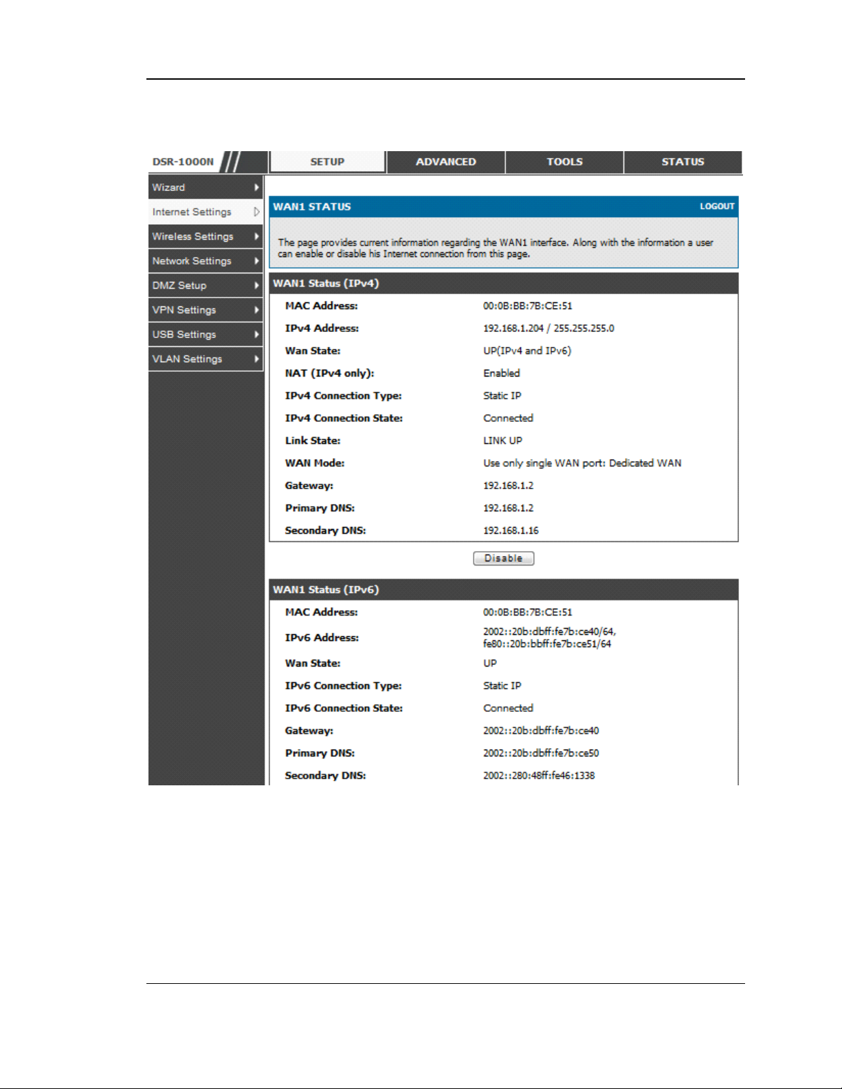
Unified Services Router User Manual
Figure 25: Connection Status informatio n for both WAN ports
The WAN status page allows you to Enable or Disable s tatic WA N links. For WAN
settings that are dynamically received from the ISP, you can Renew or Releas e the
link parameters if required.
46
Page 49
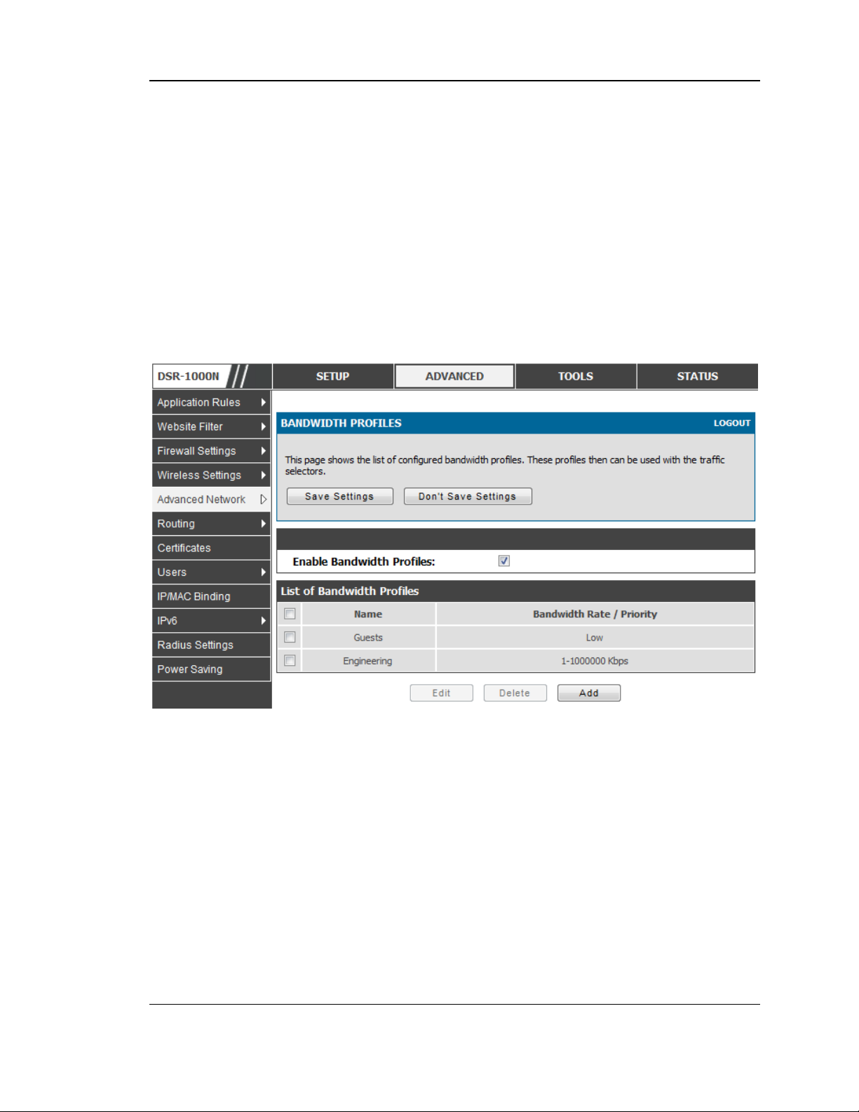
Unified Services Router User Manual
3.3 Bandwidth Controls
Advanced > Advanced Network > Traffic Management > Bandwidth Profiles
Bandwidth profiles allow you to regulate the traffic flow from the LAN to WAN 1 or
WAN 2. This is useful to ensure that low priority LAN us ers (like guests or HTTP
service) do not monopolize the av a ilable WA N’s b a n dwid t h fo r co s t -savings or
bandwidth-priority-allocation purpos es.
Bandwidth profiles configuration consists of enabling the band width control feature
from the GUI and adding a profile which defines the control parameters . The profile
can then be associated with a traffic selector, so that bandwidth profile can be applied
to the traffic matching the s electors . Selectors are elements like IP address es or
services that would trigger the configured bandwidth regulation.
Figure 26: List of Configured Bandwidth Profile s
To create a new bandwidth profile, click Add in the List of Bandwidth Profiles . The
following configuration parameters are used to define a bandwidth profile:
Profile Name: This identifier is used to associate the configured profile to the
traffic s elector
You can choos e to limit the bandwidth either using priority or rate.
If u sin g p rio rit y “ Lo w” , “H ig h ”, and “Mediu m” can b e s e lec t ed . If there
is a low priority profile ass ociated with traffic selector A and a high
priority profile associated with traffic selector B, then the WAN
bandwidth allocation preference will be to traffic s elector B packets .
47
Page 50
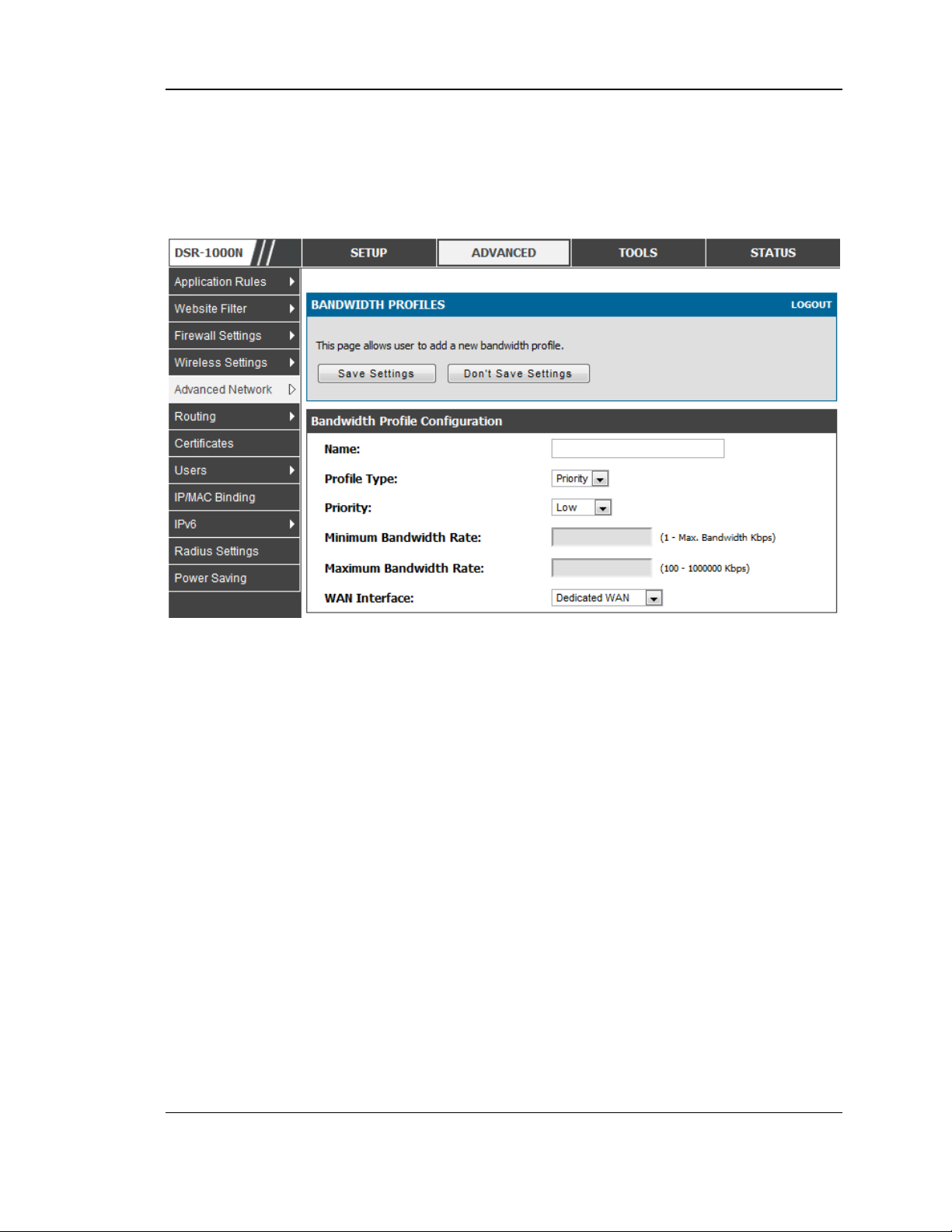
Unified Services Router User Manual
For finer control, the Rate profile type can be used. With this option the
minimum and maximum bandwidth allowed by this profile can be limited.
Choose the WAN interface that the profile s hould be ass ociated with .
Figure 27: Bandwidth Profile Configuratio n page
Advanced > Advanced Network > Traffic Management > Traffic Selectors
Once a profile has been created it can then be associated with a traffic flow from the
LAN to WAN. To create a traffic selector, click Add on the Traffic Selectors page.
Traffic selector configuration binds a bandwidth profile to a type or s ource of LAN
traffic with the following settings:
Available profiles : Ass ign one of the defined bandwidth profiles
Service: You can have the selected bandwidth regulation apply to a specific
service (i.e. FTP) from the LAN. If you do not s ee a service that you want, you
can configure a custom service through the Advanced > Firewall Settings >
Custom Services page. To have the profile apply to all services , selec t A NY.
Traffic Selector Match Type: this defines the parameter to filter against when
applying the bandwidth profile. A s pecific machine on the LAN can be
identified via IP address or MAC address , or the profile can apply to a LA N
port or VLAN group. As well a wireles s network can be selected by its BSSID
for bandwidth shaping.
48
Page 51
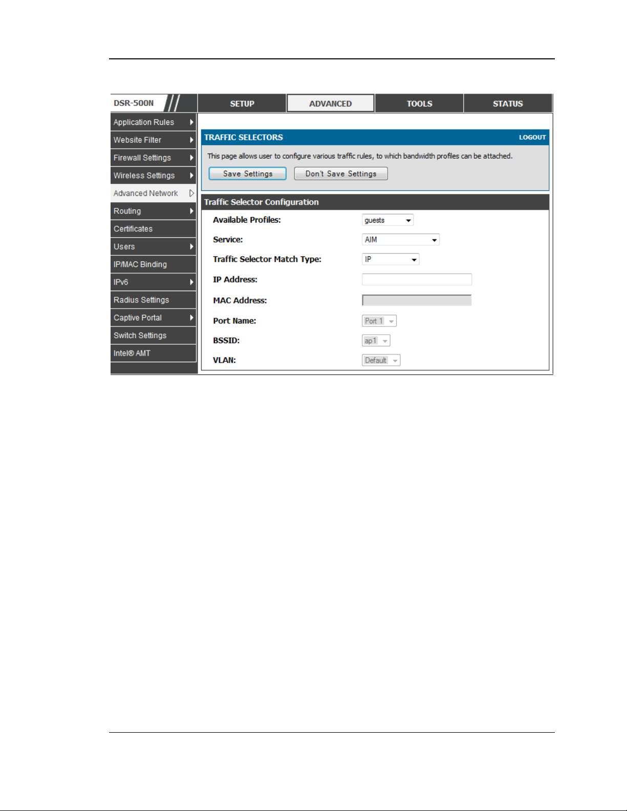
Unified Services Router User Manual
Figure 28: Traffic Selector Configuratio n
3.4 Features with Multiple WAN Links
This router supports multiple WAN links . This allows you to take advantage of
failover and load balancing features to ensure certain internet dependent services are
prioritized in the event of uns table WAN connectivity on one of the ports.
Setup > Internet Settings > WAN Mode
To use Auto Failover or Load Balancing, WAN link failure detection must be
configured. This involves accessing DNS servers on the internet or ping to an internet
address (us er defined). If required, you can configure the number of retry attempts
when the link seems to be d isconnected or the threshold of failures that determines if
a W AN port is down.
3.4.1 Auto Failover
In this case one of your W AN ports is ass igned as the primary internet link for all
internet traffic. The secondary WAN port is us ed for redundancy in case the primary
link goes down for any reason. Both WAN ports (primary and secondary) must be
con fig u red to co n ne c t to th e res p e c t ive ISP’s befo r e e n a b lin g t his featu re. The
secondary WAN port will remain unconnected until a failure is detected on the
primary link (either port can be assigned as the primary). In the event of a failure on
the primary port, all internet traffic will be rolled over to the backup port. When
configured in Auto Failover mode, the link status of the primary WAN port is
checked at regular intervals as defined by the failure detection settings.
49
Page 52

Unified Services Router User Manual
Note that both WAN1, WAN2 and WA N3 can be configured as the primary internet
link.
Auto-Rollover us ing WAN port
Primary WA N: Selected WAN is the primary link ( WAN1/WAN2/WAN3)
Secondary WAN: Selected WAN is the s econdary link.
Failover Detection Settings: To check connectivity of the primary internet link, one
of the following failure detection methods can be selected:
DNS lookup us ing WAN DNS Servers: DNS Lookup of the DNS Servers of
the primary link are used to detect primary WAN connectivity.
DNS lookup using DNS Servers : DNS Lookup of the custom DNS Servers
can be specified to check the connectivity of the primary link.
Ping thes e IP address es : Thes e IP's will be pinged at regular intervals to
check the connectivity of the primary link.
Retry Interval is : The number tells the router how often it s hould run the
above configured failure detection method.
Failover after: This sets the number of retries after which failover is
initiated.
3.4.2 Load Balancing
This fea t u re allo ws y o u to us e mu lt iple W A N lin ks (an d pr es u mab ly mu ltip le ISP’s )
simultaneous ly. After configuring more than one WAN port, the load balancing
optio n is available to carry traffic over more than one link. Protocol bindings are
used to s egregate and assign s ervices over one WAN port in order to manage
internet flow. The co nfigured failure detection method is used at regular intervals on
all configured WAN ports when in Load Balancing mode.
DSR currently s upport three algorithms for Load Balancing:
Round Robin: This algorithm is particularly useful when the connection speed of
one W AN port greatly differs from another. In this case you can define protocol
bindings to rou te low-latency services (such as VOIP) over the high er-speed link
and let low-volume background traffic (such as SMTP) go over the lower speed link.
Protocol binding is explained in next s ection.
Spill Over: If Spill Over method is selected, WAN1 acts as a dedicated link till a
threshold is reached. After this , WAN2 will be use d for new connections. You can
configure s pill-over mode by using following options:
Load Tolerance: It is the percentage of bandwidth after which the router
switches to secondary WAN.
Max Bandwidth: This sets the maximum bandwidth tolerable by the primary
WAN.
If the link bandwidth goes above the load tolerance value of max bandwidth, the
router will s pill-over the next connections to secondary WAN.
For example, if the maximum bandwidth of primary WAN is 1 Kbps and the load
tolerance is set to 70. Now every time a new connection is established the
bandwidth increases. After a certain number of connections say bandwidth reached
50
Page 53

Unified Services Router User Manual
70% of 1Kbps , the new connections will be s pilled -over to secondary WAN. The
maximum value of load tolerance is 80 and the least is 20.
Protocol Bindings : Refer Section 3.4.3 for details
Load balancing is particularly useful when the connection speed of one WAN port
greatly differs from another. In this case you can define protocol bindings to route
low-latency services (s uch as VOIP) over the higher-speed link and let low-volume
background traffic (such as SMTP) go over the lower speed link.
51
Page 54
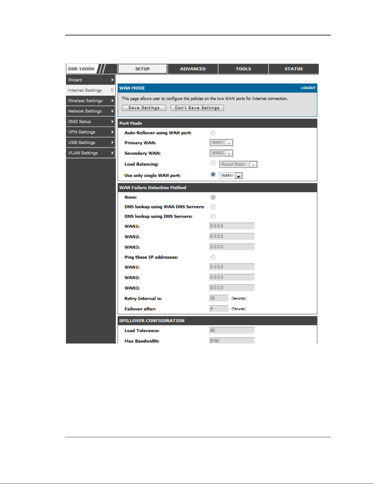
Unified Services Router User Manual
Figure 29: Load Balancing is available when multiple WAN ports are
configured and Protocol Bindings have been defined
3.4.3 Protocol Bindings
Advanced > Routing > Protocol Bindings
Protocol bindings are required when the Load Balancing feature is in us e. Choos ing
from a list of configured services or any of the us er-defined services , the type of
traffic can be as signed to go over only one of the available WAN ports . For
increased flexibility the source network or machines can be specified as well as the
destinatio n network or machines. For example the VOIP traffic for a set of LAN IP
addresses can be assigned to one WAN and any VOIP traffic from the remaining IP
52
Page 55
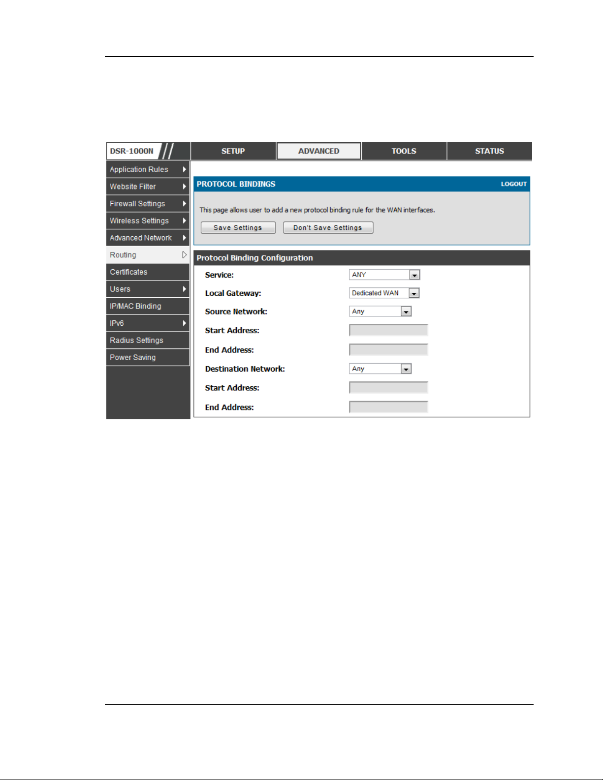
Unified Services Router User Manual
addresses can be assigned to the other WAN link. Protocol bindings are only
applicable when load balancing mode is enabled and more than one WAN is
configured.
Figure 30: Protocol binding setup to associate a service and/or LAN
source to a WAN and/or destination network
3.5 Routing Configuration
Routing between the LAN and WAN will impact the way this router handles traffic
that is received on any of its physical interfaces. The routing mode of the gateway is
core to the behaviour of the traffic flow between the secure LAN and the internet.
3.5.1 Routing Mode
Setup > Internet Settings > Routing Mode
This device supports clas sical routing, network address translation (NAT), and
transport mode routing.
With clas sical routing, devices on the LAN can be directly accessed from the
internet by their public IP addresses (assuming appropriate firewall s ettings). If
your ISP has ass igned an IP address for each of the computers that you use,
select Clas sic Routing.
53
Page 56

Unified Services Router User Manual
NAT is a technique which allows several computers on a LAN to share an
Internet connection. The computers on the LAN us e a "private" IP addres s
range while the WAN port on the router is configured with a single "public" IP
address. Along with connection sharing, NA T als o hides internal IP addres ses
from the computers on the Internet. NAT is required if your ISP has assigned
only one IP address to you. The compute rs that connect through the router will
need to be ass igned IP address es from a private subnet .
Trans parent routing between the LAN and WAN does not perform NAT.
Broadcast and multicast packets that arrive on the LAN interface are switched
to the WAN and vice versa, if they do not get filtered by firewall or VPN
policies. To maintain the LAN and WAN in the same broadcas t domain s elect
Trans parent mode, which allows bridging of traffic from LAN to WA N and vice
vers a, except for router-terminated traffic and other management traffic. All
DSR features (such as 3G modem support) are supported in trans parent mode
ass uming the LA N and WAN are configured to be in the s ame broadcast
domain.
NA T ro utin g h a s a featu re ca lled “NA T Hair-p innin g” that allo ws in t e rnal ne twork
users on the LAN and DMZ to access internal servers (eg. an internal FTP server)
using their externally-kn own d oma in n a me . Th is is als o re ferred to a s “NAT
lo o p ba c k” s ince LAN genera t e d tra ffic is re d ire c t e d th ro ug h t h e fir ewa ll to reach
LAN servers by their external name.
54
Page 57
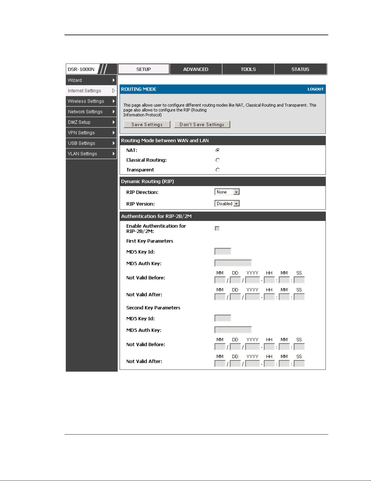
Unified Services Router User Manual
Figure 31: Routing Mode is use d to configure traffic routing betwe en
WAN and LAN, as we ll as Dynamic routing (RIP)
55
Page 58

Unified Services Router User Manual
3.5.2 Dynamic Routing (RIP)
DSR- 150/150N/250/250N does not support RIP.
Setup > Internet Settings > Routing Mode
Dynamic routing us ing the Routing Information Protocol (RIP) is an Interior
Gateway Protocol (IGP) that is common in LANs. With RIP this router can exchange
routing information with other supported routers in the LAN and allow for d ynamic
adjus tment of routing tables in order to adapt to modifications in the LAN without
interrupting traffic flow.
The RIP direction will define how this router sends and receives RIP packets.
Choose between:
Both: The router both broadcas ts its routing table and also process es RIP
information received from other routers. This is the recommended setting in
order to fully utilize RIP capabilities.
Out Only: The router broadcasts its routing table periodically but does not
accept RIP information from other routers.
In Only: The router accepts RIP information from other routers, but does not
broadcas t its routing table.
None: The router neither broadcasts its route table nor does it accept any
RIP packets from other routers. This effectively disables RIP.
The RIP version is dependent on the RIP support of other routing
devices in the LAN.
Disabled: This is the setting when RIP is dis abled.
RIP-1 is a class -bas ed routing version that does not include subnet
information. This is the mos t commonly supported vers ion.
RIP-2 includes all the functionality of RIPv1 plus it s upports subnet
information. Though the data is sent in RIP-2 format for both RIP-2B and
RIP-2M, the mode in which packets are sent is different. RIP-2B broadcasts
data in the entire s ubnet while RIP-2M sends data to multicas t address es.
If RIP-2B or RIP-2M is the selected version, authentication between this router and
other routers (configured with the same RIP version) is required. MD5
authentication is used in a first/s econd key exchange p rocess . The authentication
key validity lifetimes are configurable to ens ure that the routing information
exchange is with current and s upported routers detected on the LAN.
56
Page 59

Unified Services Router User Manual
3.5.3 Static Routing
Advanced > Routing > Static Routing
Advanced > IPv6 > IPv6 Static Routing
Manually adding static routes to this device allows you to define the path selection
of traffic from one interface to another. There is no communication between this
router and other devices to account for changes in the path; once co nfigured the
static route will be active and effective until the network changes.
The List of Static Routes displays all routes that have been added manually by an
administrator and allows s everal operations on the static routes. The List of IPv4
Static Routes and List of IPv6 Static Routes share the same fields (with one
exception):
Name: Name of the route, for identification and management .
Active: Determines whether the route is active or inactive. A route can be
added to the table and made inactive, if not needed. This allows routes to be
used as needed without deleting and re-adding the entry. An inactive route is
not broadcas t if RIP is enabled.
Private: Determines whether the route can be shared with other routers when
RIP is enabled. If the route is made private, then the route will not be s hared
in a RIP broadcast or multicas t. This is only applicable for IPv4 static
routes .
Des tination: the route will lead to this destination host or IP address .
IP Subnet Mas k: This is valid for IPv4 networks only, and identifies the
subnet that is affected by this static route
Interface: The physical network interface (W AN1, WAN2, WAN3, DMZ or
LAN), through which this route is access ible.
Gateway: IP address of the gateway through which the destination hos t o r
network can be reached.
Metric: Determines the priority of the route. If multiple routes to the same
destination exist, the route with the lowes t metric is chos en.
57
Page 60
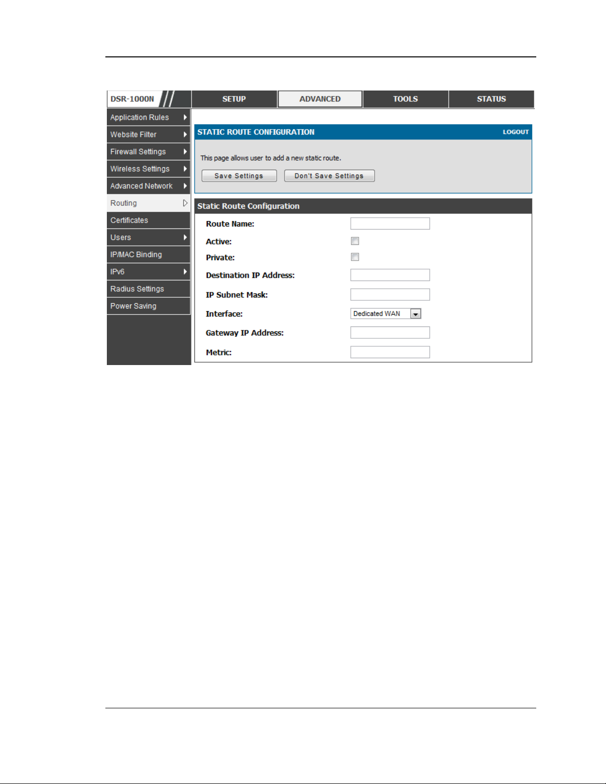
Unified Services Router User Manual
Figure 32: Static route configuration fields
3.5.4 OSPFv2
Advanced > Routing > OSPF
OSPF is an interior gateway protocol that routes Internet Protocol (IP) packets solely
within a single routing domain. It gathers link state information from available routers
and constructs a topology map of the network.
OSPF version 2 is a routing protocol which described in RFC2328 - OSPF Version 2.
OSPF is IGP (Interior Gateway Protocols).OSPF is widely us ed in large networks
such as ISP backbone and enterprise networks.
58
Page 61
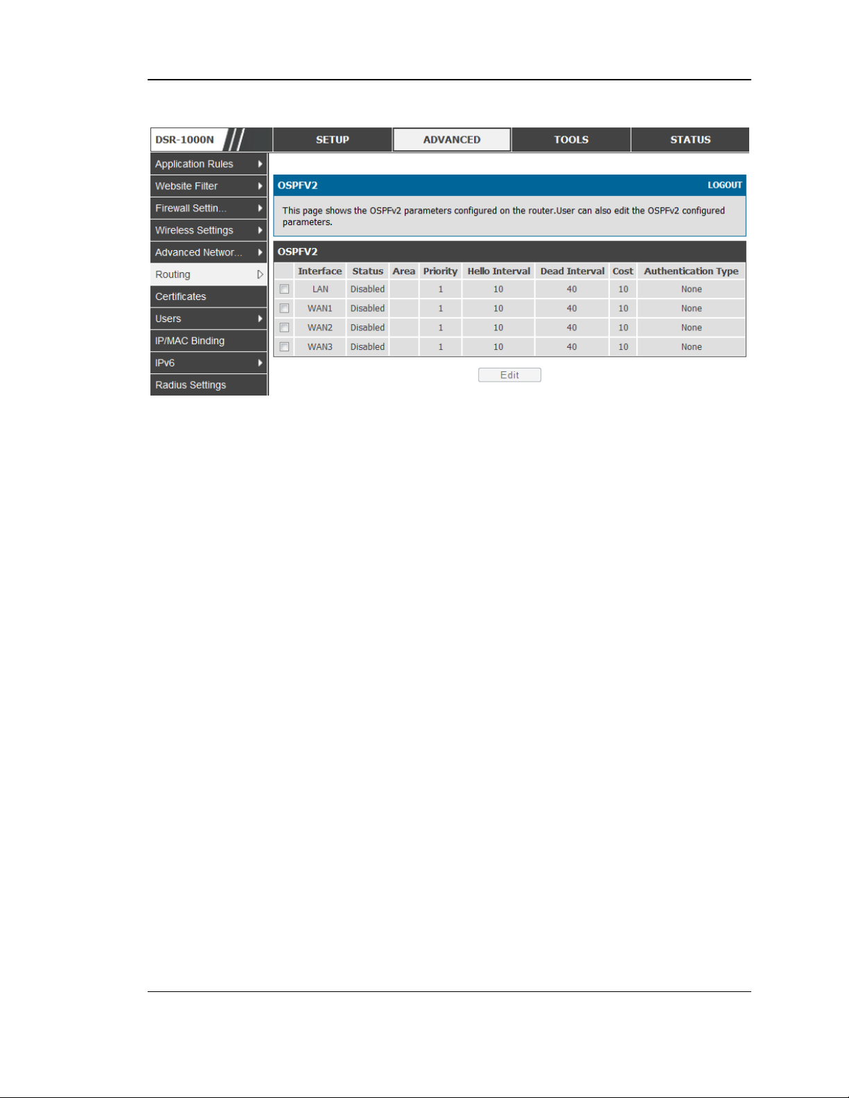
Unified Services Router User Manual
Figure 33: OSPFv2 configured paramete rs
Interface: The phys ical network interface on which OSPFv2 is Enabled/Disabled.
Statu s: This column dis plays the Enable/Disable state of OSPFv2 for a particular
interface.
Area: The area to which the interface belongs. Two routers having a common
segment; their interfaces have to belong to the same area on that s egment. The
interfaces should belong to the s ame subnet and have s imilar mas k.
Priority: Helps to determine the OSPFv2 designated router for a network. The router
with the highes t priority will be more eligible to become Designated Router. Setting
the value to 0, makes the router ineligible to become Designated Router. The default
value is 1.Lower value means higher priority.
HelloInterval: The number of seconds for HelloIn terval timer value . Setting this
value, Hello packet will be sent every timer value seconds on the specified interface.
This value must be the same for all routers attached to a common network. The
default value is 10 seconds.
DeadInterval: The number of seconds that a device’s h e llo packe t s mus t not h a ve been
seen before its neighbours declare the OSPF router down. This value must be the
same for all routers attached to a common network. The default value is 40 seconds.
OSPF requires these intervals to be exactly the same b etween two neighbours . If any
of these intervals are different, thes e routers will not become neighbours on a
particular segment
Cos t: The cost of s ending a packet on an OSPFv2 interface.
Authentication Type:. This column displays the type of authenticatio n to be used for
OSPFv2.If Authentication type is none the interface does not authenticate ospf
packets . If Authentication Type is Simple then ospf packets are authenticated us ing
simple text key. If Authentication Type is MD5 then the interface authenticates os pf
packets with MD5 authentication.
59
Page 62
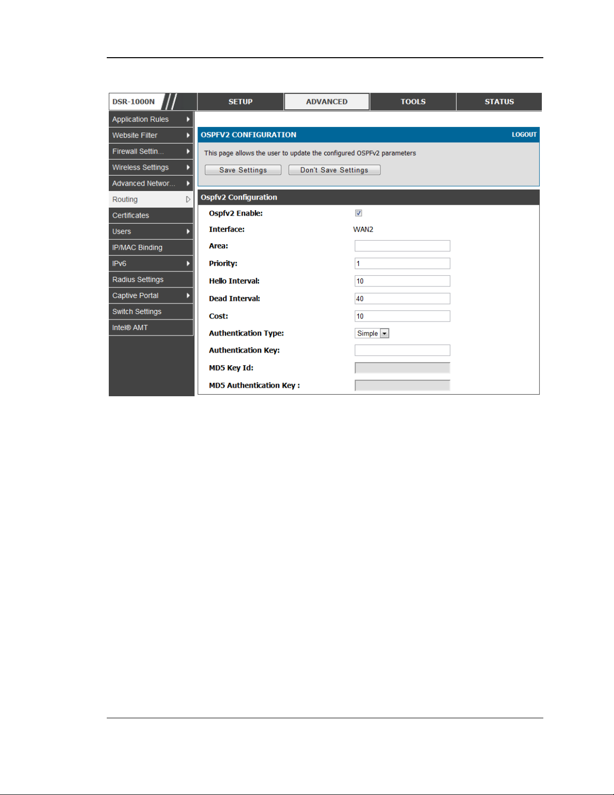
Unified Services Router User Manual
Figure 34: OSPFv2 configuration
3.5.5 OSPFv3
Advanced > IPv6 > OSPF
Open Shortest Path First version 3 (OSPFv3) suppo rts IPv6 . To enable an OSPFv3
proces s on a router, you need to enable the OSPFv3 process globally, ass ign the
OSPFv3 process a router ID, and enable the OSPFv3 process on related interfaces
60
Page 63
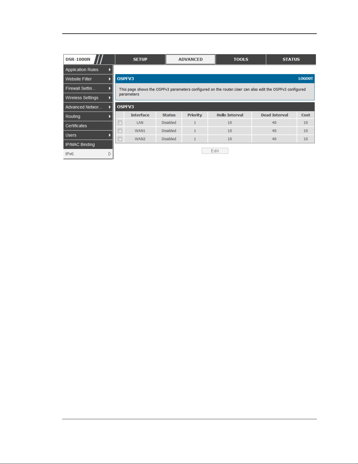
Unified Services Router User Manual
Figure 35: OSPFv3 configured parameters
Interface: The physical network interface on which OSPFv3 is Enabled/Dis abled.
Statu s: This column dis plays the Enable/Disable state of OSPFv3 for a particular
interface.
Priority: Helps to determine the OSPFv3 designated router for a network. The router
with the highes t priority will be more eligible to become Designated Router. Setting
the value to 0, makes the router ineligible to become Designated Router. The default
value is 1.Lower Value means hig her priority.
HelloInterval: The number of seconds for HelloInterval timer value. Setting this
value, Hello packet will be sent every timer value seconds on the s pecified interface.
This value must be the same for all routers attached to a common network. The
default value is 10 seconds.
DeadInterval: Th e n u mbe r of s ec onds that a device ’s hello p a ckets mus t not h a ve been
seen before its neig hbours declare the OSPF router down.This value must be the same
for all routers attached to a common network. The default value is 40 seconds.
OSPF requires these intervals to be exactly the same between two neighbours . If any
of thes e intervals are different, these routers will not become neighbours on a
particular segment
Cos t: The cost of s ending a packet on an OSPFv3 interface.
61
Page 64
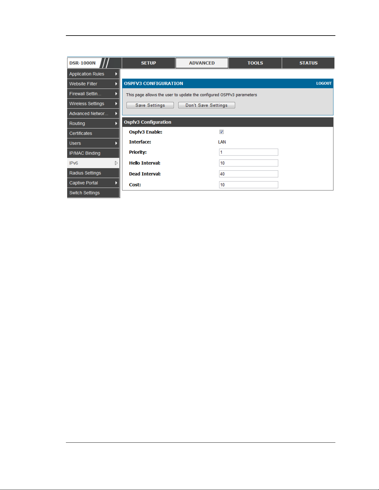
Unified Services Router User Manual
Figure 36: OSPFv3 configuration
3.5.6 6to4 Tunneling
Advanced > IPv6 > 6to4 Tunneling
6to4 is an Internet transition mechanism for migrating from IPv4 to IPv6,
a system that allows IPv6 packets to be transmitted over an IPv4
network. Select the check box to Enable Automatic Tunneling and
allow traffic from an IPv6 LAN to be sent over a IP v4 Option to reach a
remote IPv6 network.
62
Page 65
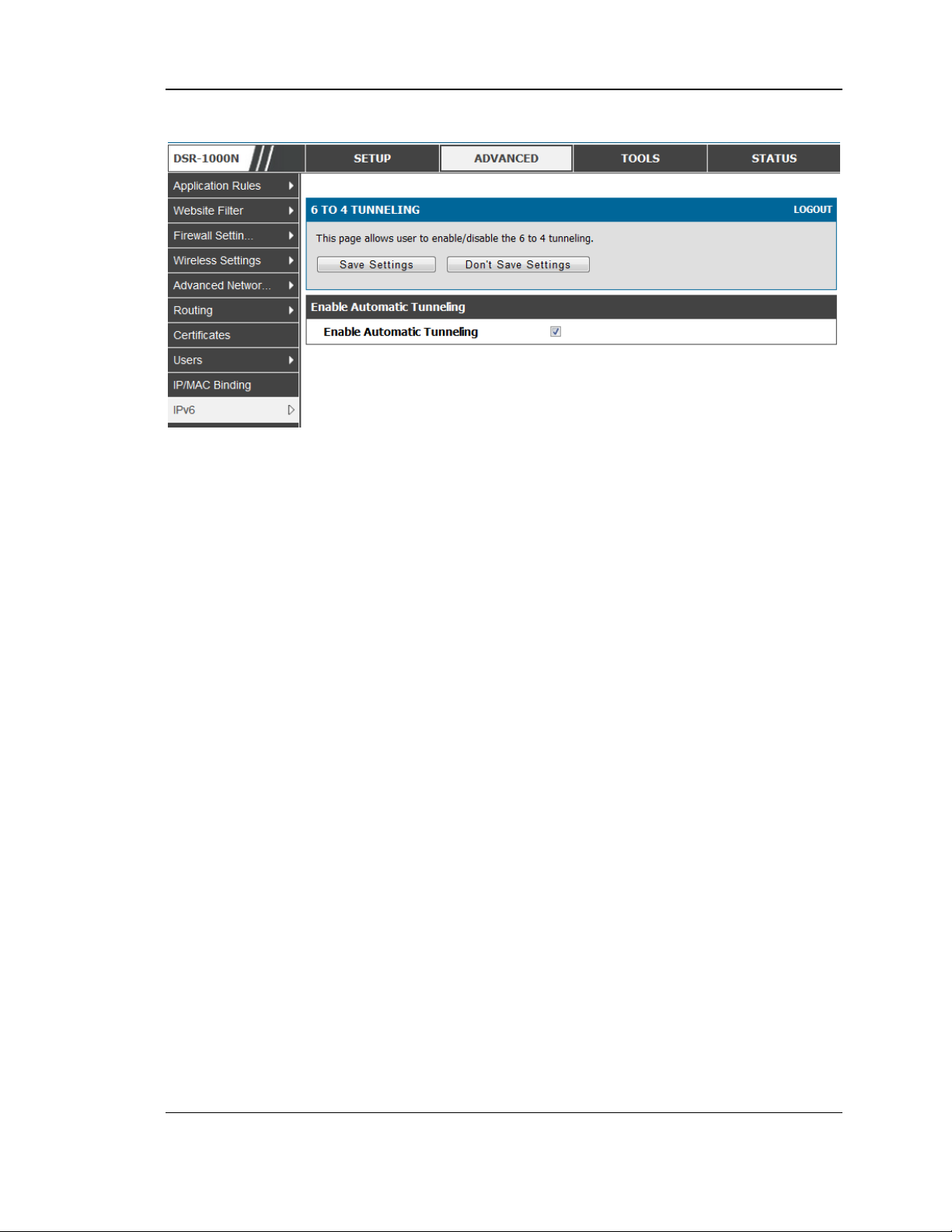
Unified Services Router User Manual
Figure 37: 6 to 4 tunneling
3.5.7 ISATAP Tunnels
Advanced > IPv6 > 6to4 Tunneling
ISATAP (Intra-Site Automatic Tunnel Address ing Protocol) is an IPv6
transition mechanism meant to transmit IPv6 packets between dual-s tack
nodes on top of an IPv4 network. ISATAP specifies an IPv6-IPv4
compatibility addres s format as well as a means for site border router
dis covery. ISATAP also specifies the operation of IPv6 over a specific
link layer - that being IPv4 us ed as a link layer for IPv6.
63
Page 66
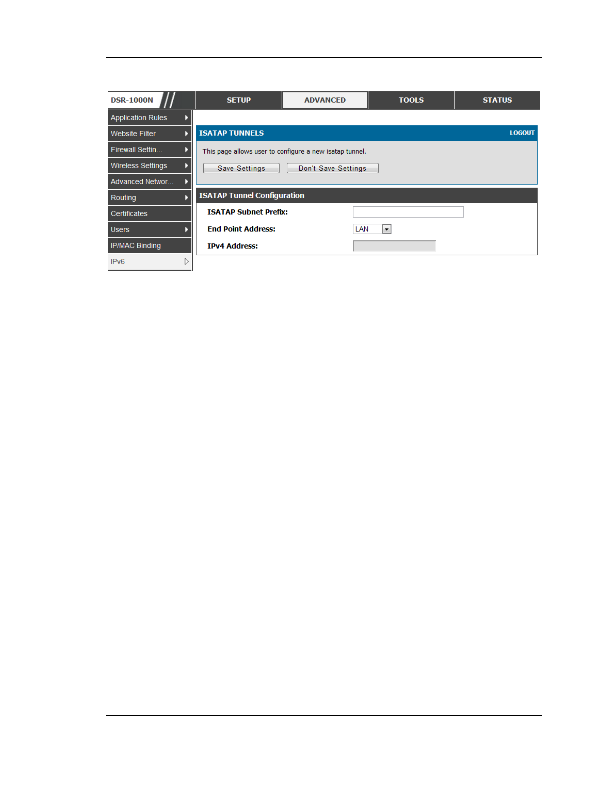
Unified Services Router User Manual
Figure 38: ISATAP Tunnels Configuration
ISATAP Subnet Prefix: This is the 64-bit s ubnet prefix that is assigned
to the logical ISATAP subnet for this intranet. This can be obtained from
your ISP or internet registry, or derived from RFC 4193.
End Point Address: Th is is the endpoint address for the tunnel that s tarts
with this router. The endpoint can be the LAN interface (as suming the
LAN is an IPv4 network), or a s pecific LAN IPv4 addres s.
IPv4 Address : The end point address if not the entire LAN.
3.6 Configurable Port - WAN Option
This router s upports one of the physical ports to be configured as a secondary WAN
Ethernet port or a dedicated DMZ port. If the port is s elected to be a secondary WAN
interface, all configuration pages relating to WAN2 are enabled.
3.7 WAN 3 (3G) Configuration
This router s upports one of the physic al ports WAN3 to be configured for 3G internet
access.
Setup > Internet Settings > WAN3 Setup
WAN3 configuration for the 3G USB modem is available only on W AN3 interface.
There are a few key elements of WAN 3 co nfiguration.
Reconnect Mode: Select one of the following options
o A lways On: The connection is always on. Username: Enter the username
required to log in to the ISP.
64
Page 67

Unified Services Router User Manual
o On Demand: The conn ection is automatically ended if it is idle for a
specified number of minutes . Enter the number of minutes in the
Maximum Idle Time field. This feature is useful if your ISP charges you
based on the amount of time that you are connected.
Pas sword: Enter the pass word required to login to the ISP.
Dial Number: Enter the number to dial to the ISP.
Authentication Protocol: Select one of None, PAP or CHAP Authentication
Protocols to connect to the ISP.
APN: Enter the APN (Access Point Name) provided by the ISP.
Domain Name S ystem (DNS) Servers
Domain name servers (DNS) convert Internet names such as www.dlink.com, to
IP addresses to route traffic to the correct resources on the Internet. If you
configure your router to get an IP address dynamically from the ISP, then you
need to s pecify the DNS server source in this section.
DNS Server Source: Choos e one of the following options :
o Get Dynamically from ISP: Choose this option if your ISP did not ass ign
a s tatic DNS IP address .
o Use These DNS Servers: Choose this option if your ISP ass igned a s tatic
DNS IP address for you to us e. Also complete the fields that are
highlighted white in this section.
o Primary DNS Server: Enter a valid primary DNS Server IP Address .
o Secondary DNS Server: Enter a valid s econdary DNS Server IP Address .
Configurable Port: This page allows you to assign the functionality intended for
the Configurable Port. Choose from the following options :
o W AN: If this option is selected, configure the WAN3. The WAN Mode
optio ns are now available as there are two W AN ports for the gateway.
o DMZ: If this option is selected, you are able to configure the DMZ port
on the DMZ Configuration menu.
Click Save Settings to save your changes .
Click Don't Save Settings to revert to the previous settings .
65
Page 68
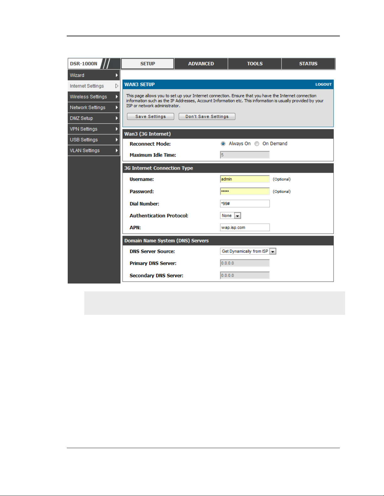
Unified Services Router User Manual
Figure 39: WAN3 configuration for 3G inte rnet
3G W AN support is available on these dual WA N products : DSR-1000 and DSR-
1000N.
Cellular 3G internet access is available on WAN3 via a 3G USB modem for DSR1000 and DSR-1000N. The cellular ISP that provides the 3G data plan will provide
the authentication requirements to establish a connection. The dial Number and APN
are specific to the cellular carriers. Once the connection type settings are configured
and saved, navigate to the WAN s tatus page (Setup > Internet Settings > WAN3
Status) and Enable the WAN3 link to establish the 3G connection.
3.8 WAN Port Settings
Advanced > Advanced Network > WAN Port Setup
The physical port settings for each WAN link can be defined here. If your ISP account
defines the WAN port speed or is as sociated with a MAC address, this information is
required by the router to ensure a smooth connection with the network.
66
Page 69
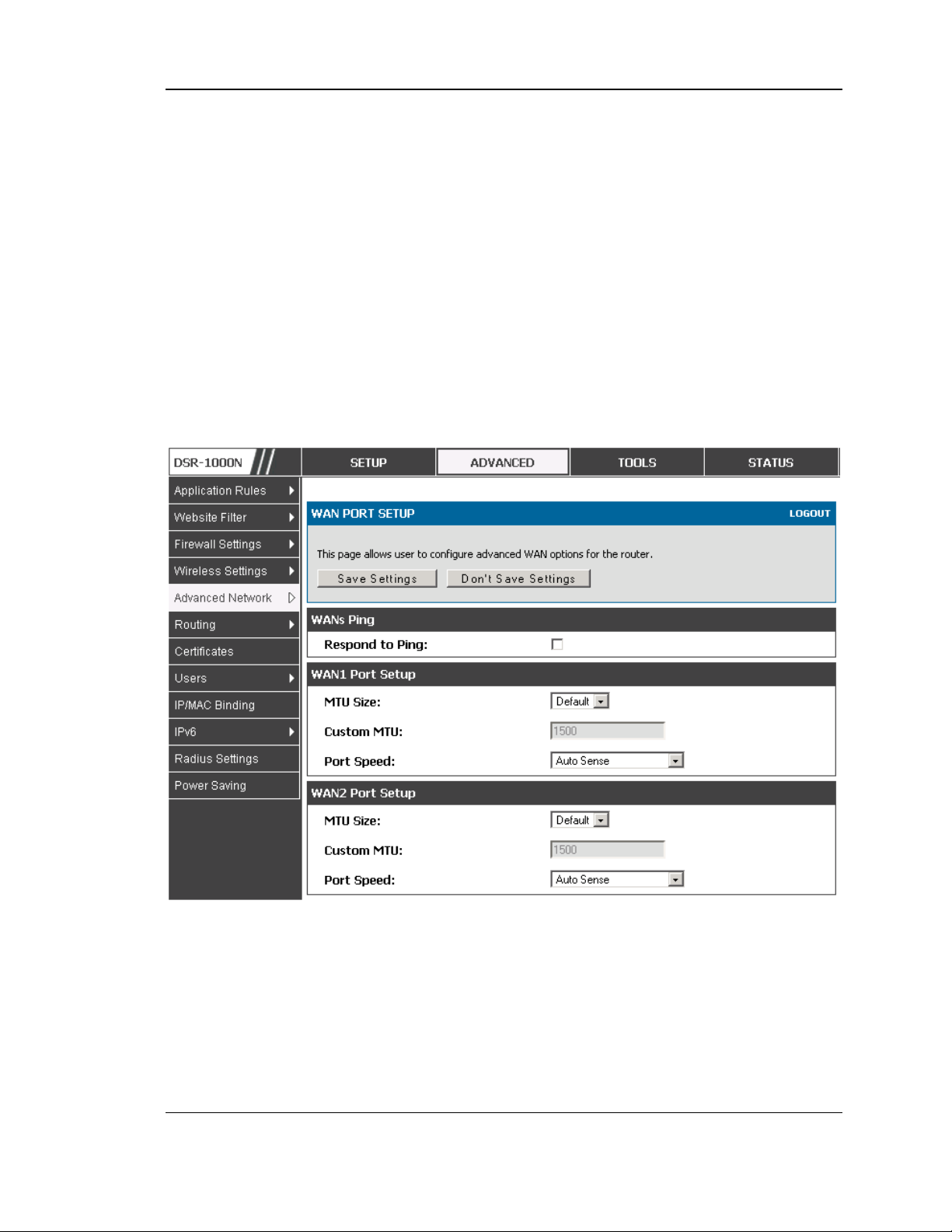
Unified Services Router User Manual
The default MTU size supported by all ports is 1500. This is the largest packet size
that can pass through the interface without fragmentation. This size can be increas ed,
however large packets can introduce network lag and bring down the interface s peed.
Note that a 1500 byte size packet is the largest allow ed by the Ethernet protocol at the
network layer.
The port s peed can be sensed by the router when Auto is s elected. With this option the
optimal port s ettings are determined by the router and network. The duplex (half or
full) can be defined based on the port support, as well as one of three port s peeds: 10
Mbps , 100 Mbps and 1000 Mbps (i.e. 1 Gbps). The default setting is 100 Mbps for all
ports.
The default MAC addres s is defined during the manufacturing process for the
interfaces , and can uniquely identify this router. You can cust omize each W A N po rt’s
MAC address as needed, either by letting the WAN port ass ume the current LAN
h o s t’s M A C a d d r es s o r b y en t e rin g a M A C a d d res s man u a lly.
Figure 40: Physical WAN port settings
67
Page 70

Unified Services Router User Manual
Chapter 4. Wireless Access Point
Setup
This router has an integrated 802.11n radio that allows you to create an access point for
wireles s LAN clients. The security/encryption/authentication options are grouped in a
wireles s Profile, and each configured profile will be available for selection in the AP
configuration menu. The profile defines various parameters for the AP, including the
security between the wireles s client and the A P, and can be s hared between multiple
APs ins tances on the same device when needed.
The content in this s ection is applicable to the DSR-500N and DSR-1000N
products.
Up to four unique wireless networks can be created b y con fig u rin g mu lt iple “virtual”
APs. Each such virtual AP appears as an independent AP (unique SSID) to supported
clients in the environment, but is actually running on th e same physical radio integrated
with this router.
You will need the following information to configure your wireless network:
Types of devices expected to access the wireless network and their s upported W i-
Fi™ modes
The ro u t e r’s geographical region
The s ecurity settings to use for securing the wireles s network.
Profiles may be thought of as a grouping of AP parameters that can then be applied
to not just one but multiple AP instances (SSIDs), thus avoiding duplication if the
same parameters are to be us ed on multiple AP instances or SSIDs .
4.1 Wireless Settings Wizard
Setup > Wizard > Wireless Settings
The Wireles s Network Setup Wizard is available for us ers new to networking. By
going through a few s traightforward configuration pages you can enable a Wi -Fi™
network on your LAN and allow supported 802.11 clients to connect to the configured
Access Point.
68
Page 71
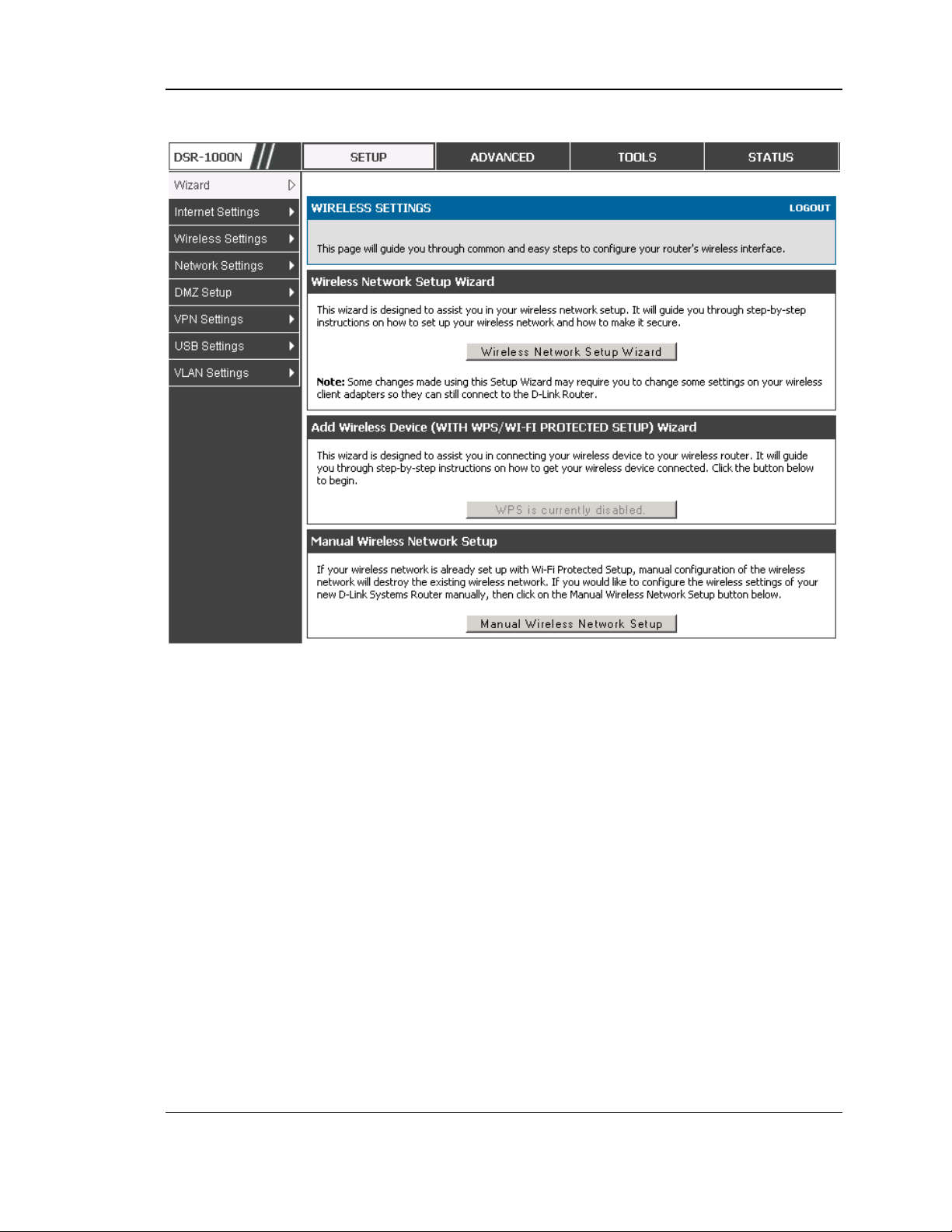
Unified Services Router User Manual
Figure 41: Wireless Ne twork Setup Wizards
4.1.1 Wireless Network Setup Wizard
This wizard provides a step -by-step guide to create and secure a new access point on
the router. The network name (SSID) is the AP id entifier that will be detected by
supported clients. The Wizard uses a TKIP+AES cipher for W PA / W PA2 s ecurity;
depending on support on the client side, devices associate with this AP us ing either
WPA or WPA2 security with the s ame pre-shared key.
The wizard has the option to automatically generate a network key for the AP. This
key is the pre-shared key for W PA or WPA2 type security. Supported clients that
have been given this PSK can as sociate with this AP. The default (auto-ass igned)
PS K is “p as s phra s e” .
The last s tep in the Wizard is to click the Connect button, which confirms the
settings and enables this AP to broadcast its availability in the LA N.
4.1.2 Add Wireless Device with WPS
With WPS enabled on your router, the selected access point allows supported WPS
clients to join the network very eas ily. When the Auto op tion for connecting a
69
Page 72

Unified Services Router User Manual
wireles s device is chose, you will be pres ented with two common W PS setup
optio ns:
Pers onal Identification Number (PIN): The wireless device that supports
WPS may have an alphanumeric PIN, and if entered in this field the AP will
establish a link to the client. Click Connect to complet e s etup and connect to
the client.
Push Button Configuration (PBC): for wireless devices that support PBC,
pres s and hold down on this button and within 2 minutes, click the PBC
connect button. The AP will detect the wireles s device and es tablis h a link
to the client.
You need to enable at least one AP with WPA/WPA2 security and als o enable WPS
in the Advanced > Wireless Settings > WPS page to us e the WPS wizard.
4.1.3 Manual Wireless Network Setup
This button on the Wizard page will link to the Setup> Wireless Settings> Access
Points page. The manual options allow you to create new APs or modify the
parameters of APs created by the Wizard.
4.2 Wireless Profiles
Setup > Wireless Settings > Profiles
The profile allows you to assign the security type, encryption and authentication to
u s e when con ne ctin g t he AP t o a wire le s s clie n t . Th e defa u lt mo de is “op en ” , i.e . n o
security. This mode is insecure as it allows any compatible wireles s clients to connect
to an AP configured with this security profile.
To create a new profile, use a unique profile name to identify the combination of
settings. Configure a unique SSID that will be the identifier us ed by the clients to
communicate to the AP us ing this profile. By choosing to broadcast the SSID,
compatible wireless clients wit h in ran g e o f th e A P c a n de t e c t th is p rofile’s
availability.
The AP offers all advanced 802.11 security modes, including WEP, WPA, WPA2 and
WPA+WPA 2 options. The security of the Access point is configured by the Wireless
Security Type s ection:
Open: sele c t t h is o p tio n to create a p u blic “ o p e n” netwo rk t o a llow u n a uthe ntic a t e d
devices to access this wireless gateway.
WEP (Wired Equivalent Privacy): this option requires a s tatic (pre -shared) key to
be s hared between the AP and wireless client . Note that WEP does not support
802.11n data rates; is it appropriate for legacy 802.11 connections.
70
Page 73
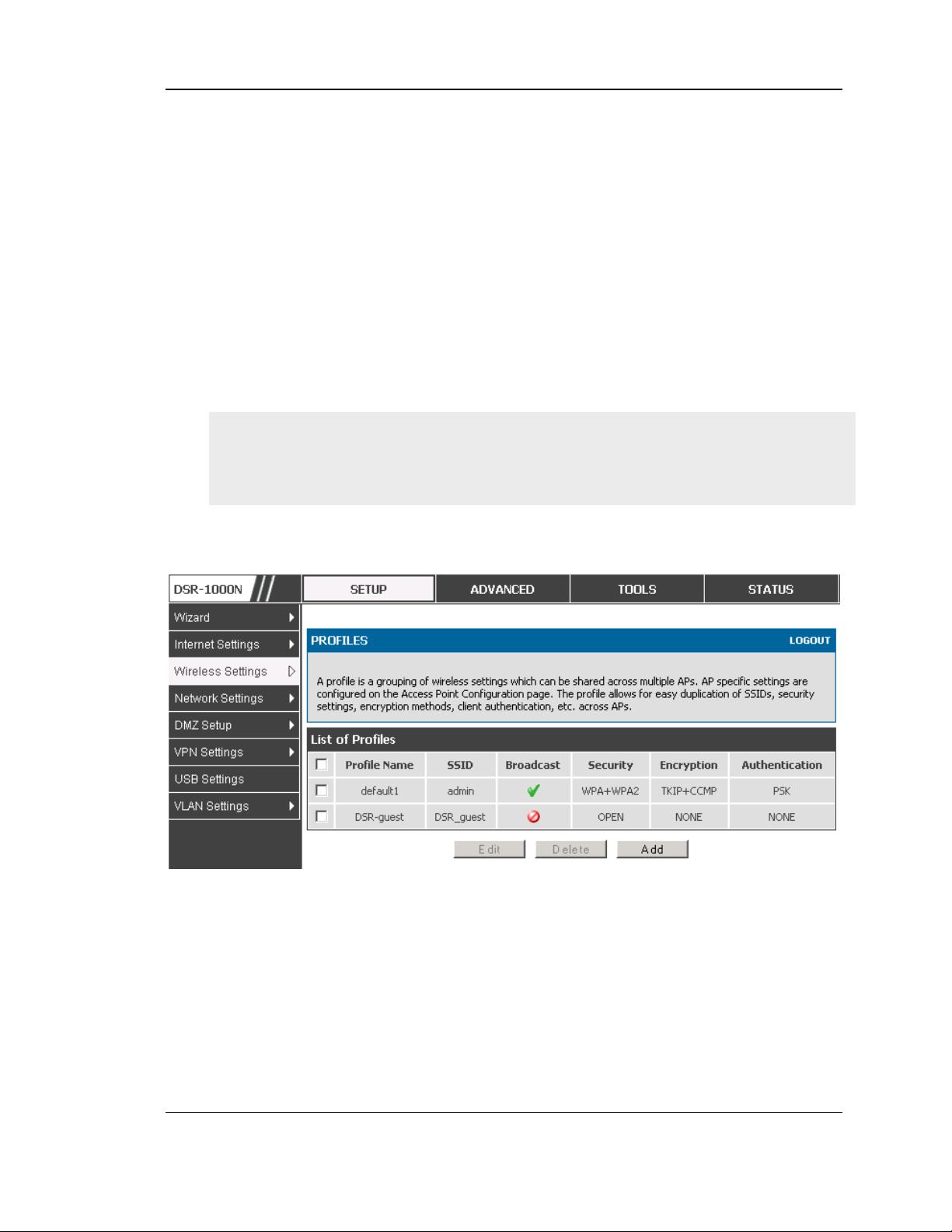
Unified Services Router User Manual
WPA (W i-Fi Protected Access): For s tronger wireless s ecurity than WEP, choos e
this option. The encryption for WPA will use TKIP and als o CCMP if required. The
authentication can be a pre-shared key (PSK), Enterprise mode with RADIUS
server, or both . Note that WPA does not support 802.11n data rates; is it
appropriate for legacy 802.11 connections.
WPA2: this s ecurity type uses CCMP encryption (and the option to add TKIP
encryption) on either PSK (pre-s hared key) or Enterprise (RADIUS Server)
authentication.
WPA + WPA2: this us es both encryption algorithms , TKIP and CCMP. WPA
clients will us e TKIP and WPA2 clients will use CCMP encryption algorithms .
“ W PA +W PA2” is a s e c urit y optio n that allo ws d e vic es to c o n ne c t t o an A P u sin g
the strongest security that it supports. This mode allows legacy devices that only
support W PA2 keys (such as an older wireles s printer) to connect to a s ecure AP
where all the other wireless clients are us ing WPA2.
Figure 42: List of Available Profiles shows the options available to
se cure the wireless link
4.2.1 WEP Security
If W EP is the chosen security option, you mus t set a unique s tatic key to be shared
with clients that wis h to access this s ecured wireles s network. This static key can be
generated from an easy-to-remember passphrase and the s elected encryption length.
Authentication: select between Open System, or Shared Key schemes
71
Page 74

Unified Services Router User Manual
Encryption: select the encryption key size -- 64 bit W EP or 128 bit W EP.
The larger size keys provide stronger encryption, thus making the key more
difficult to crack
WEP Pass phrase: enter an alphanumeric phrase and click Generate Key to
generate 4 unique WEP keys with length determined by the encryption key
size. Next choose one of the keys to be used for authentication. The s elected
key must be shared with wireless clients to connect to this d evice.
72
Page 75
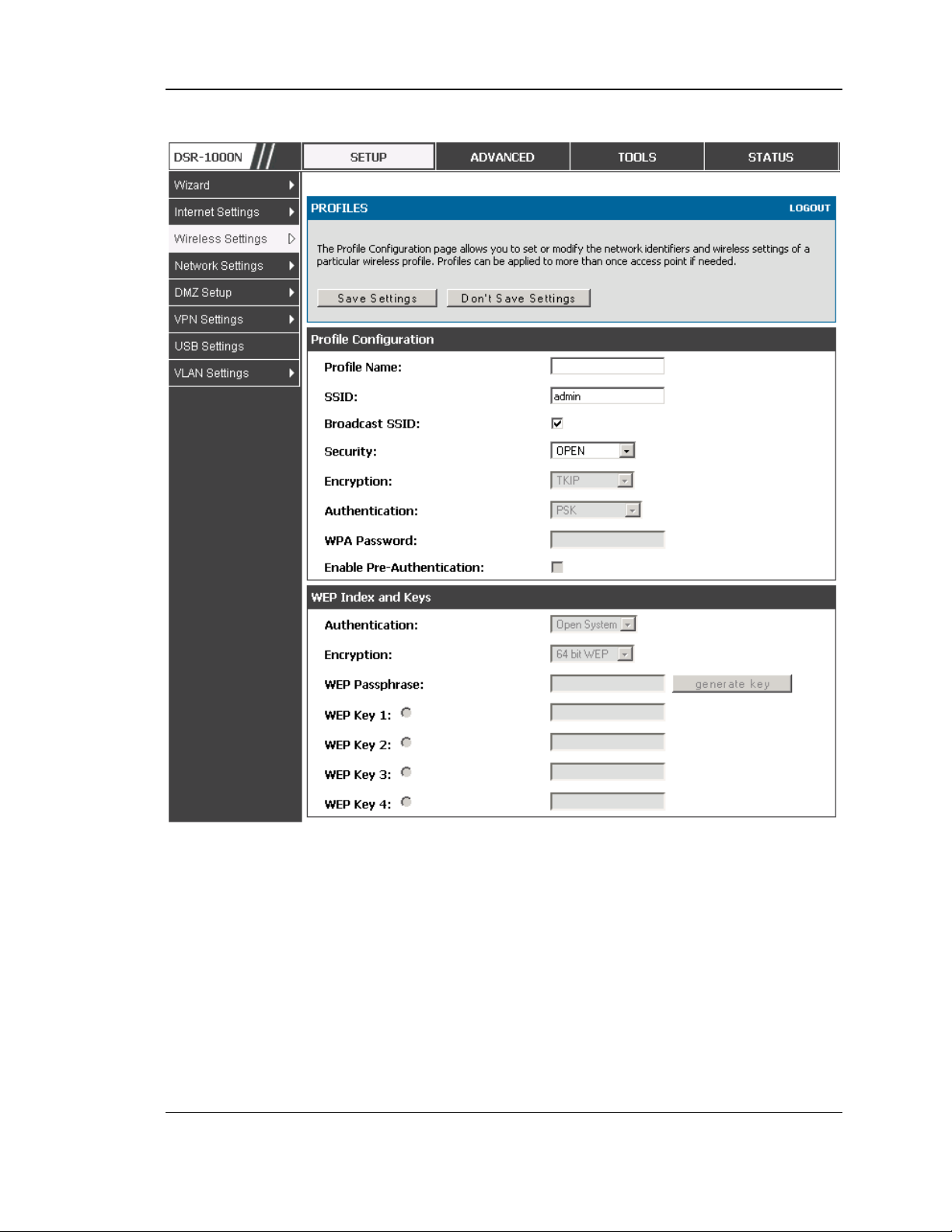
Unified Services Router User Manual
Figure 43: Profile configuration to se t ne twork security
4.2.2 WPA or WPA2 with PSK
A pre-shared key (PSK) is a known passphrase configured on th e AP and client both
and is us ed to authenticate the wireless client. A n acceptable passphrase is between
8 to 63 characters in length.
4.2.3 RADIUS Authentication
Advanced > RADIUS Settings
Enterprise Mode uses a RADIUS Server for WPA and/or WPA2 security. A
RADIUS server mus t be configured and acces sible by the router to authen ticate
73
Page 76

Unified Services Router User Manual
wireles s client connections to an AP enabled with a profile that uses RADIUS
authentication.
The Authentication IP Addres s is required to identify the s erver. A
secondary RADIUS server provides redundancy in the event that the primary
server cannot be reached by the router when needed.
Authentication Port: the port for the RADIUS server connection
Secret: enter the shared secret that allows this router to log into the
specified RADIUS server(s). This key mus t match the shared s ecret on the
RADIUS Server.
The Timeout and Retries fields are used to either move to a secondary server
if the primary cannot be reached, or to give up the RADIUS authentication
attempt if communication with the server is not pos sible.
74
Page 77
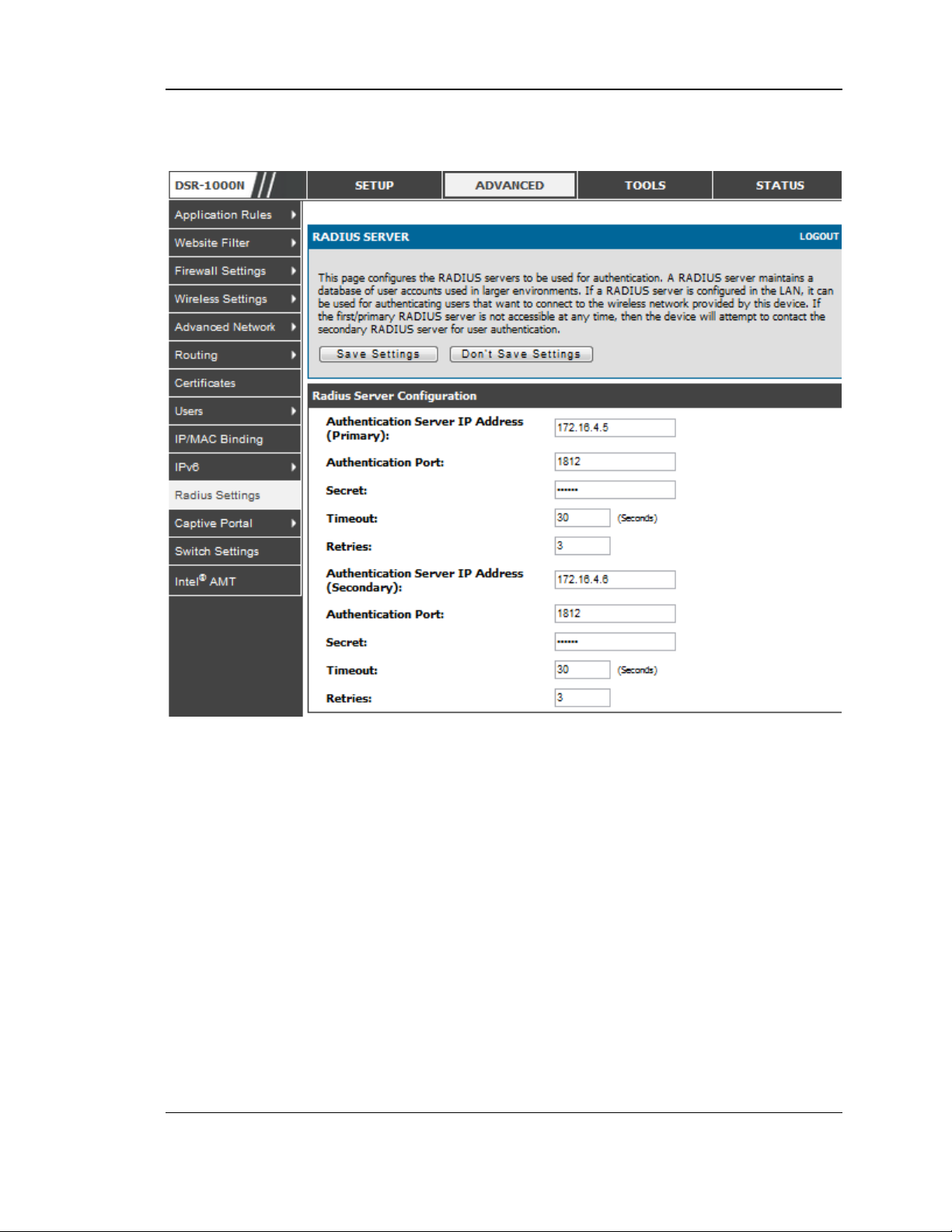
Unified Services Router User Manual
Figure 44: RADIUS server (External Authenticatio n) configuration
4.3 Creating and Using Access Points
Setup > Wireless Settings > Access Points
Once a profile (a group of security settings) is created, it can be assigned to an AP on
the router. The AP SSID can be configured to broadcas t its availability to the 802.11
environment can be used to establish a W LAN network.
The AP configuration page allows you to create a new A P and link to it one of the
available profiles. This router s upports multiple AP’ s re ferred t o as v irt u a l a c ces s
points (VAPs ). Each virtual AP that has a unique SSIDs appears as an independent
access point to clients . Th is v aluable featu re allo ws th e ro u t e r’s ra d io to b e
configured in a way to optimize s ecurity and throughput for a group of clients as
re q u ire d b y th e us e r. To create a VAP, clic k th e “ad d ” bu t t o n o n t h e Setup >
Wireless Settings > Access Points page. A fter setting the AP name, the profile
dropdown menu is used to select one of the configured profiles .
75
Page 78
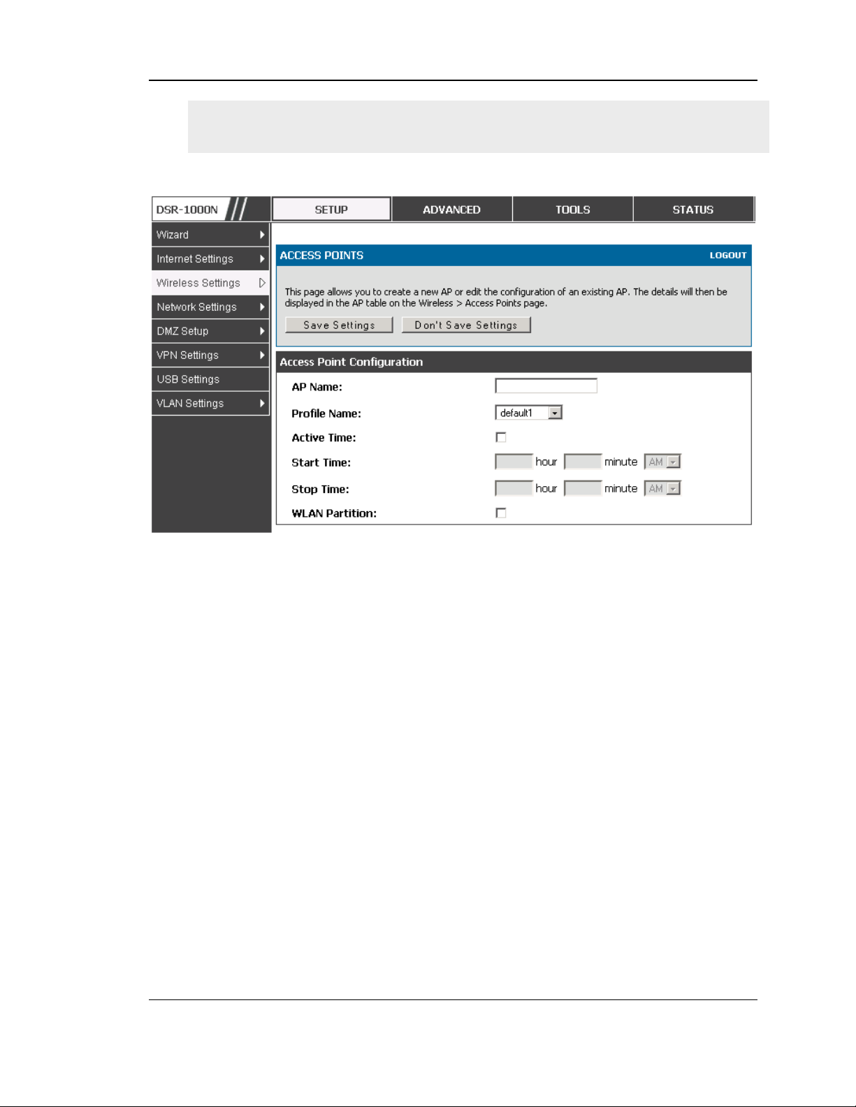
Unified Services Router User Manual
The AP Name is a unique identifier us ed to manage the AP from the GUI, and is
not the SSID that is detected by clients when the AP has broadcast enabled.
Figure 45: Virtual AP configuration
A valuable power saving feature is the start and stop time control for this AP. You
can conserve on the radio power by disabling the AP when it is not in us e. For
example on evenings and weekends if you know there are no wireless clients, the start
and stop time will enable/disable the access poin t automat ically.
Once the AP settings are config ured, you must enable the AP on the radio on the
Setup > Wireless Settings > Access Points page. The status field changes to
“Enab le d ” if th e A P is a v a ilable to accept wire le s s clie n ts. If the AP is configured to
bro adcast its SSID (a profile parameter), a green check mark indicating it is
broadcas ting will be shown in the List of Available Access points .
76
Page 79
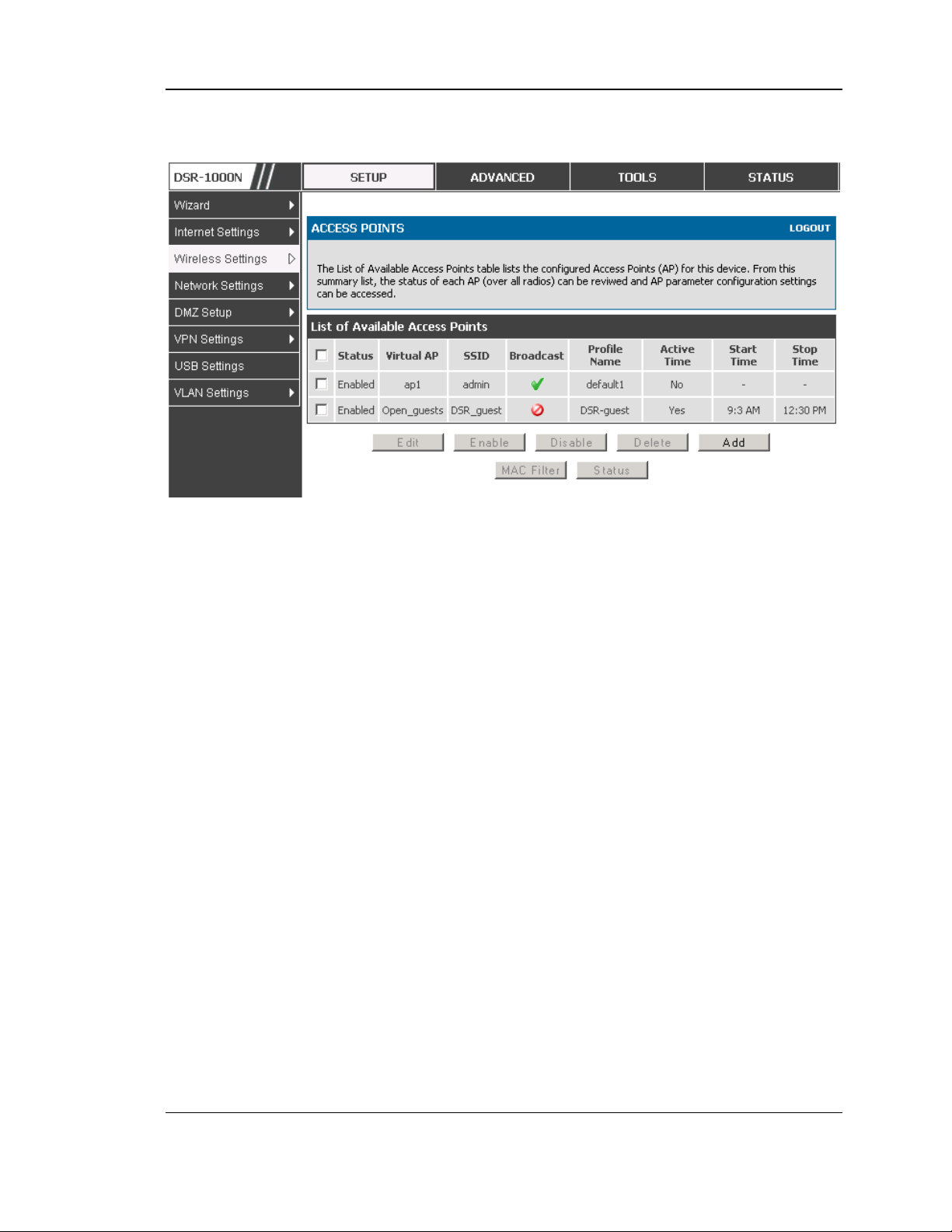
Unified Services Router User Manual
Figure 46: List of configured acces s points (Virtual APs) shows one
enable d acces s point on the radio, broadcasting its SSID
The clients connected to a particular AP can be viewed by us ing the Status Button on
the List of Available Access Points . Traffic statistics are shown for that individual
AP, as compared to the summary stats for each AP on the Statistics table. Connected
clients are sorted by the MAC address and indicate the security parameters used by
the wireless link, as well as the time connected to th is particular AP. Clicking the
Details button next to the connected client will g ive the detailed send and receive
traffic s tatistics for the wireles s link between this AP and the client.
4.3.1 Primary benefits of Virtual APs:
Optimize throughput: if 802.11b, 802.11 g, and 802.11n clients are expected
to access the LAN via this router, creating 3 VAPs will allow you to manage
or s hape traffic for each group of clients. A unique SSID can be created for
the network of 802.11b clients and another SSID can be ass igned for the
802.11n clients . Each can have different security parameters – remember,
the SSID and security of the link is determined by the profile. In this way
legacy clients can access the network without bringing down the overall
throughput of more capable 802.11n clients .
Optimize s ecurity: you may wish to s upport s elect legacy clients that only
offer WEP security while us ing WPA2 security for the majority of clients
for the radio. By creating two VAPs configured with different SSIDs and
different security parameters, both types of clients can connect to the LA N.
Since WPA2 is more secure, you may want to broadcas t this SSID and not
77
Page 80
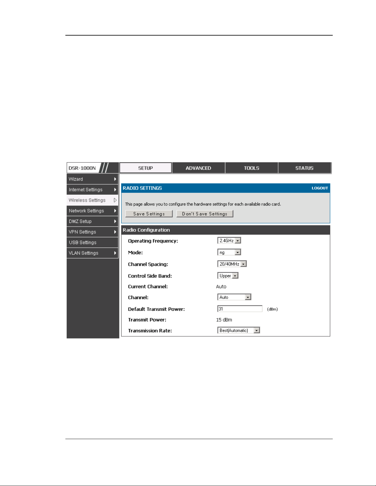
Unified Services Router User Manual
broadcast the SSID for the VAP with WEP since it is meant to be used for a
few legacy devices in this scenario.
4.4 Tuning Radio Specific Settings
Setup > Wireless Settings > Radio Settings
The Radio Settings page lets you configure t he channels and power levels available
fo r the AP’s e n a bled o n the DSR. The router has a dual band 802.11n radio, meaning
either 2.4 GHz or 5 GHz frequency of operation can be selected (not concurrently
though). Based on the selected operating frequency, the mode selection will let you
define whether legacy connections or only 802.11n connections (or both) are accepted
on configured APs.
Figure 47: Radio card configuration options
The ratified 802.11n s upport on this radio requires selecting the appropriate broadcast
(NA or NG etc.) mode, and then defining the channel spacing and control side band
for 802.11n traffic. The default s ettings are appropriate for most networks. For
example, changing the channel sp acing to 40 MHz can improve bandwidth at the
expense of s upporting earlier 802.11n clients.
The available transmission channels are governed by regulatory constraints bas ed on
the region setting of the router. The maximum transmission power is similarly
governed by regulatory limits; you have the op tion to decrease from the default
maximum to reduce the signal s trength of traffic out of the radio.
78
Page 81
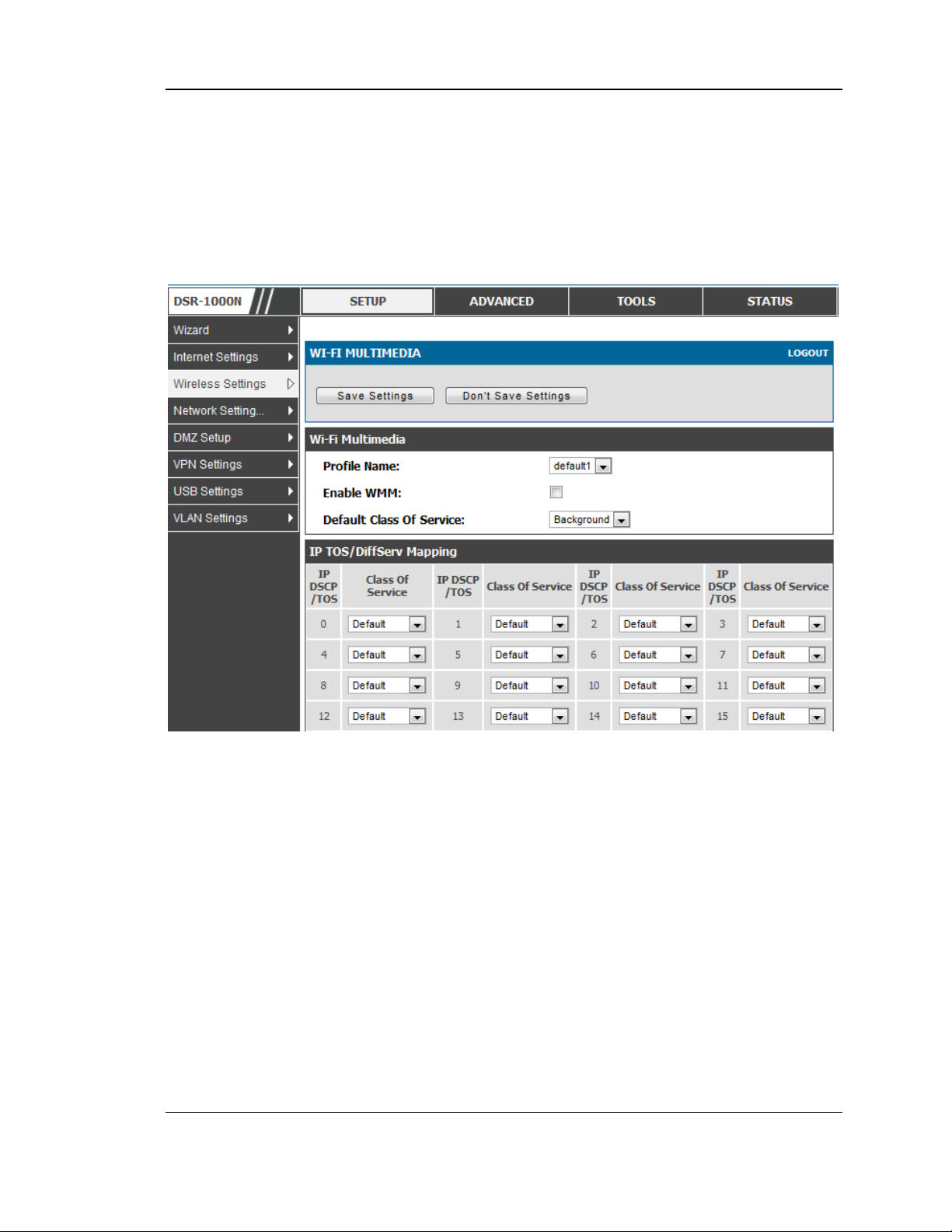
Unified Services Router User Manual
4.5 WMM
Setup > Wireless Settings > WMM
Wi-Fi Multimedia (WMM) provides basic Quality of service (QoS) features to IEEE
802.11 networks. WMM prioritizes traffic according to four Access Categories (AC) voice, video, bes t effort, and background .
Figure 48: Wi-Fi Multimedia
Profile Name:
This field allows you to s elect the available profiles in wireless settings .
Enable WMM:
This field allows you to enable WMM to improve multimedia transmission.
Default Class Of Service:
This field allows you to s elect the available Access Categories (voice, video, bes t
effort, and backgroun d).
79
Page 82
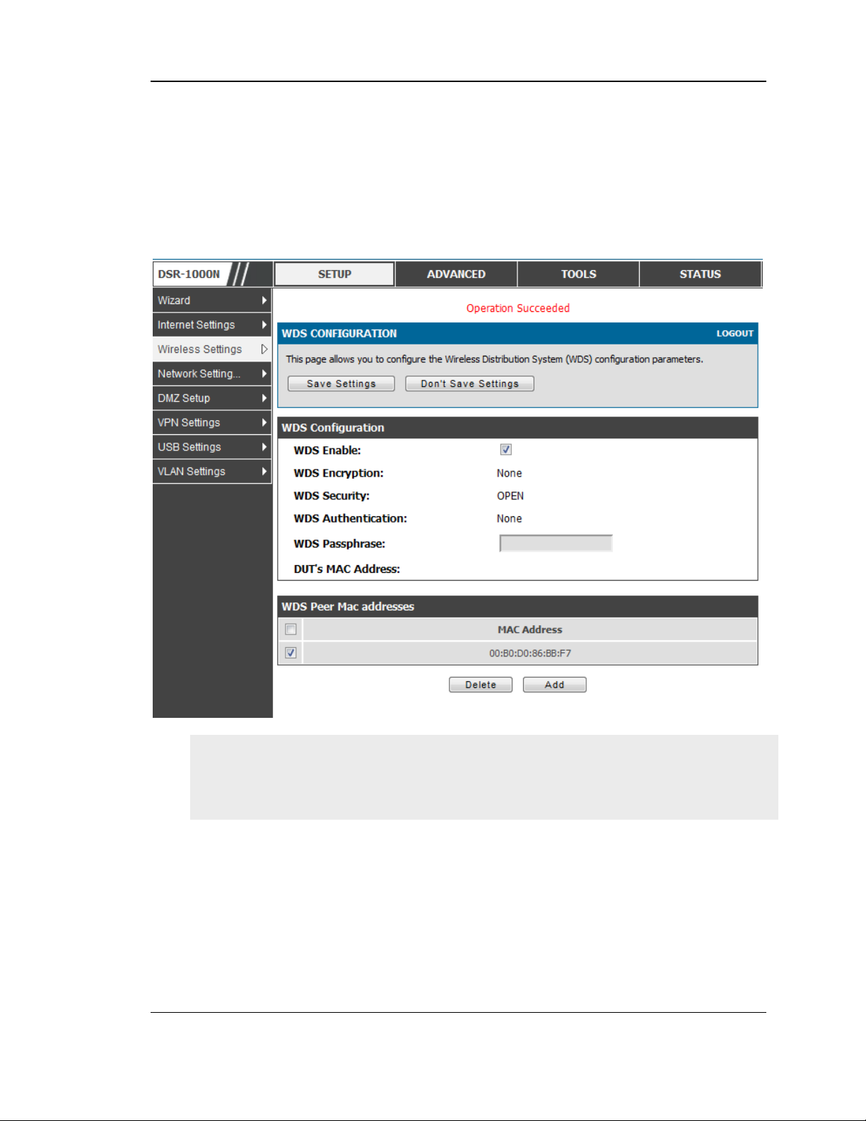
Unified Services Router User Manual
4.6 Wireless distribution system (WDS)
Setup > Wireless Settings > WDS
Wireles s distribution s ystem is a system enabling the wireles s interconnection of
access points in a network. This feature is only guaranteed to work only between
devices of the same type.
Figure 49: Wireless Distribution Sys tem
This feature is only guaranteed to work only between devices of the same type (i.e.
using the s ame chips et/driver). For example between two DSR250N boxes, or
between two DSR1000N. It should also interoperate between a DSR 1000N and
DSR 500 N boxes since they are bas ed on the same chips et/driver.
When the us er enables the WDS links use the same s ecurity configuration as the
default access point. The WDS links do not have true WPA/WPA2 support, as in there
is no WPA key handshake performed. Instead the Session Key to be us ed with a WDS
Peer is computed using a hashing function (similar to the one used for computing a
WPA PMK). The inputs to this function are a PSK (configurable by an administrator
from the WDS page) and an internal "magic" string (non -configurable).
In effect the WDS links use TKIP/AES encryption , depending on the encryption
configured for the default AP. In case the default AP us es mixed encryption (TKIP +
AES).The W DS link will use the AES encryption scheme.
80
Page 83

Unified Services Router User Manual
For a WDS link to function properly the Radio settings on the WDS peers have to
be the same.
The WDS page would consist of two s ections. The first s ection provides general WDS
settings shared by all its WDS peers.
WDS Enable - This would be a check box
WDS Encryption - Dis plays the type of encryption used. It could be one of OPEN/64
bit WEP/128 bit WEP/TKIP/AES (Us e the term being used throughout the box i.e.
either CCMP or AES).
WDS Pass phrase - This is required if th e encryption selected is TKIP/CCMP. We
would expect it to be within 8~63 A SCII characters. In the WDS configuration page
this field is mandatory and has to be same on the two WDS peers, when the s ecurity is
configured in TKIP/AES mode. The WDS links use th is as the PSK for the
connectio n.
DUT's Mac Addres s - This would be the mac address of this box. This should be
configured in the peer's WDS configuration page to be able to establish a WDS link
with this box. This field in the WDS Configuration section dis plays the device's mac
address, which needs to be s pecified on the WDS peer for making a connection to this
device (Similarly the WDS peers MAC addres s will have to be specified on this
device for the WDS link to be established between the two devices ).
The second s ection will have the list of configured WDS peers with buttons to
Add/Delete Peer entries . We support up to a maximum of 4 W DS links per box.
The both devices need to have same wireles s settings (wireless mode, encryption,
authentication method, WDS pass phras e, WDS MAC address and wireless SSID)
when we configure WDS features in DSR router.
The "Add WDS Peer" s ection allows the user to specify a W DS peer. The "WDS
Peers" table d isplays the list of WDS peers currently configured on the device. A
maximum of 4 WDS peers can be s pecified in any given mode.
4.7 Advanced Wireless Settings
Advanced > Wireless Settings > Advanced Wireless
Sophisticated wireless adminis trators can modify the 802.11 communication
parameters in this page. Generally, the default settings are appropriate for most
networks . Please refer to the GUI integrated help text for further details on the us e of
each configuration parameter.
81
Page 84
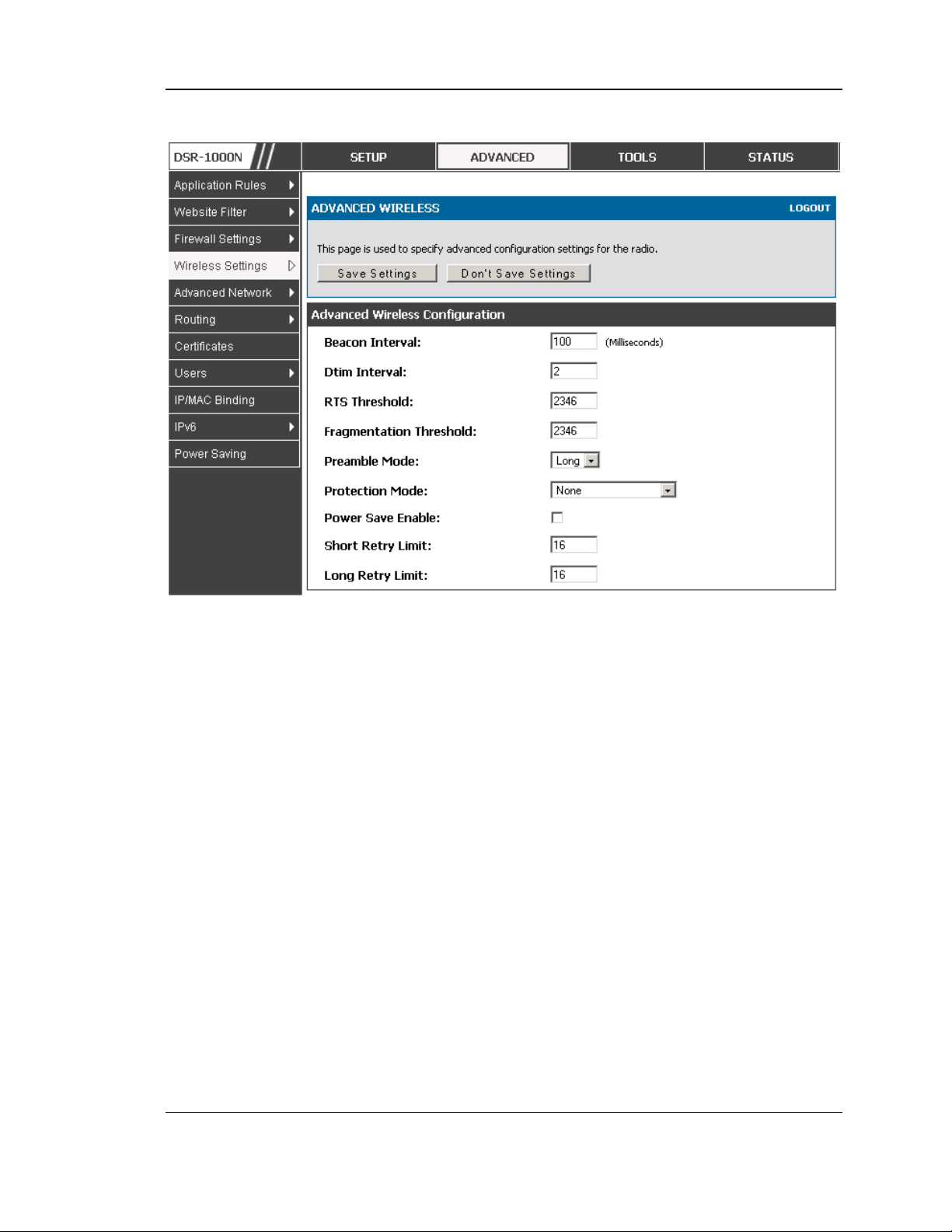
Unified Services Router User Manual
Figure 50: Advanced Wire less communic atio n se ttings
4.8 Wi-Fi Protected Setup (WPS)
Advanced > Wireless Settings > WPS
WPS is a simplified method to add supporting wireles s clien ts to the network. W PS is
only applicable for APs that employ WPA or WPA2 security. To us e WPS, select the
eligible VAPs from the dropdown list of A Ps that h ave been configured with this
security and enable WPS status for this AP.
The WPS Current Status section outlines the security, authentication, and encryption
settings of the selected AP. Th es e are co ns ist en t wit h t h e A P’s p rofile. There are two
setup options available for :
Personal Identification Number (PIN): The wireless device that supports WPS
may have an alphanumeric PIN, if so add the PIN in this field. The router will
con n e c t wit h in 60 s ec o n ds of clic kin g t h e “ Co nfig ure via PIN” b u tt o n imme d iately
below the PIN field. There is no LED indication that a client has connected.
Push Button Configuration (PBC): for wireless devices that s upport PBC, pres s
and hold down on this button and within 2 minutes click the PBC connect butt on.
The AP will detect the wireless device and establish a link to the client.
82
Page 85
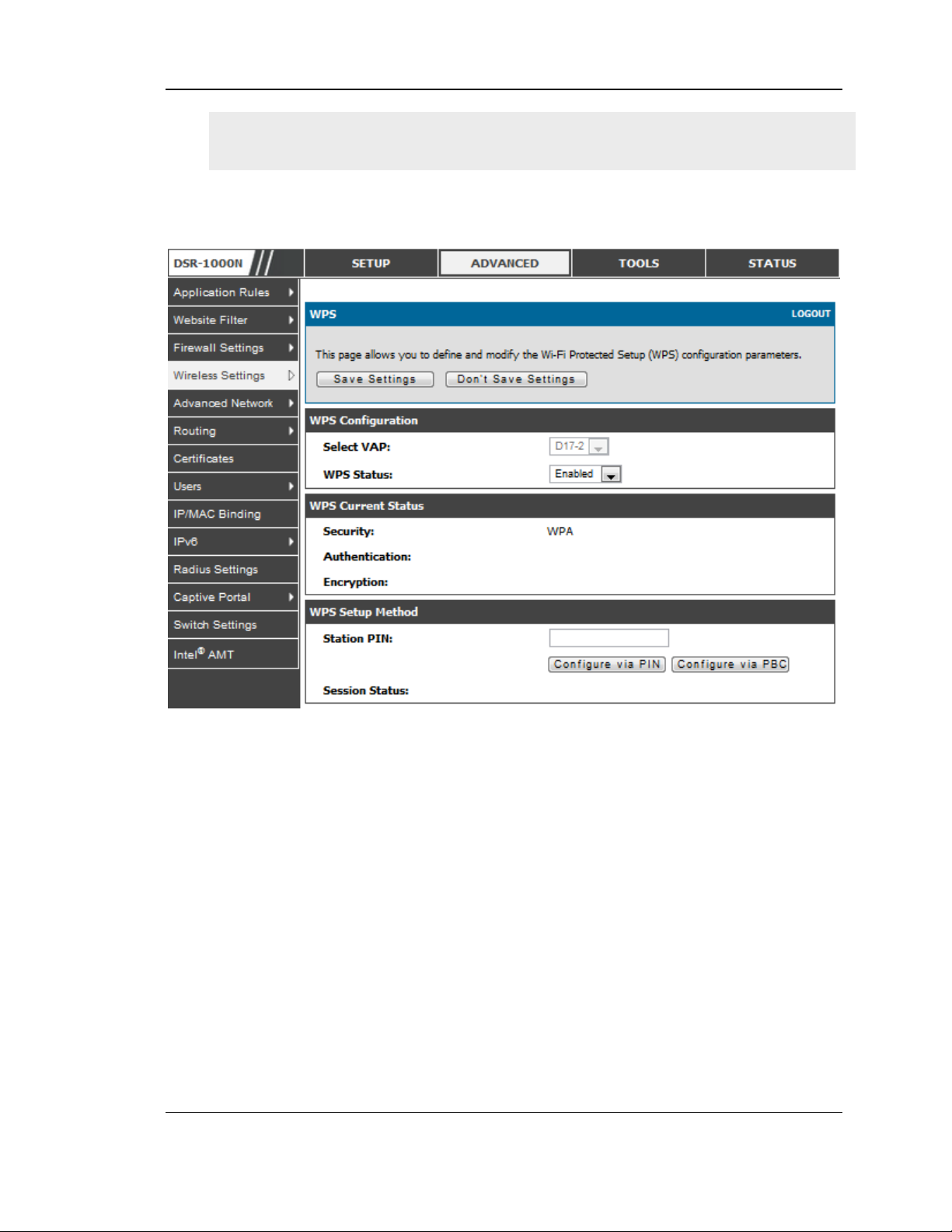
Unified Services Router User Manual
More than one AP can use WPS, but only one AP can be used to establish WPS
links to client at any given time.
Figure 51: WPS configuratio n for an AP with WPA/WPA2 profile
83
Page 86

Page 87

Chapter 5. Securing the Private
Network
You can s ecure your network by creating and applying rules that your router uses to
selectively block and allow inbound and outbound Internet traffic. You then specify
how and to wh om the rules apply. To do so, you must define the fo llowing:
Services or traffic types (example s: web brows ing, VoIP, other s tandard s ervices
and also custom services that you define)
Direction for the traffic by specifying the source and destination of t raffic; this is
d o n e b y s pec ify ing th e “From Z o n e ” (LA N/W A N/DM Z ) a n d “To Z o n e ”
(LAN/WAN/DMZ)
Schedules as to when the router s hould apply rules
Any Keywords (in a domain name or on a URL of a web page) that the router
should allow or block
Rules for allowing or blocking inbound and outbound Internet traffic for s pecified
services on specified schedules
MAC address es of devices that should not acces s the internet
Port triggers that signal the router to allow or block access to specified services as
defined by port number
Reports and alerts that you want the router to send to you
You can, for example, es tablis h restricted -access policies based on time-of-day, web
addresses, and web address keywords. You can block Internet acces s by applications
and s ervices on the LAN, such as chat rooms or games. You can block just certain
groups of PCs on your network from being acces sed by the W AN or public DMZ
network.
5.1 Firewall Rules
Advanced > Firewall Settings > Firewall Rules
Inbound (WAN to LAN/DMZ) rules restrict access to traffic entering your network,
selectively allowing only s pecific outside users to access specific local resources. By
default all access from the ins ecure WAN side are blocked from accessing the secure
LAN, except in response to requests from the LAN or DMZ. To allow outs ide devices
to access s ervices on the secure LAN, you must create an inbound firewall rule for
each s ervice.
If you wan t to allo w incomin g t raffic, y o u mu st make th e rou t e r’s W A N p o r t IP
address known to the public. This is calle d “ e xpo sin g your host.” How y o u make y o u r
address known depends on how the WAN ports are configured; for this router you
Page 88
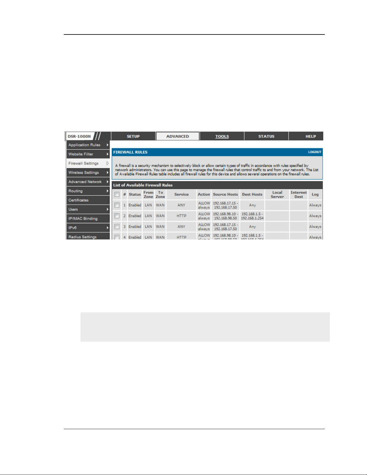
Unified Services Router User Manual
may us e the IP address if a static address is as signed to the WAN port, or if your
WAN address is dynamic a DDNS (Dyna mic DNS) name can be used.
Outbound (LAN/DMZ to WA N) rules res trict access to traffic leaving your network,
selectively allowing only s pecific local us ers to access s pecific outside resources. The
default outbound rule is to allow access from the secure zone (LAN) to either the
public DMZ or insecure W AN. On other hand the default outbound rule is to deny
access from DMZ to insecure WAN. You can change this default behaviour in the
Firewall Settings > Default Outbound Policy page. When the default outbound
policy is allow always, you can to block hos ts on the LAN from accessing internet
services by creating an outbound firewall rule for each service.
Figure 52: List of Available Fire wall Rules
5.2 Defining Rule Schedules
Tools > Schedules
Firewall rules can be enabled or disabled automatically if they are associated with a
configured schedule. The schedule configuration page allows you to define days of
the week and the time of day for a new schedule, and then this s chedule can be
selected in the firewall rule configuration page.
All s chedules will follow the time in the routers configured time zone. Refer to the
section on choos ing your Time Zone and configuring NTP s ervers for more
information.
86
Page 89
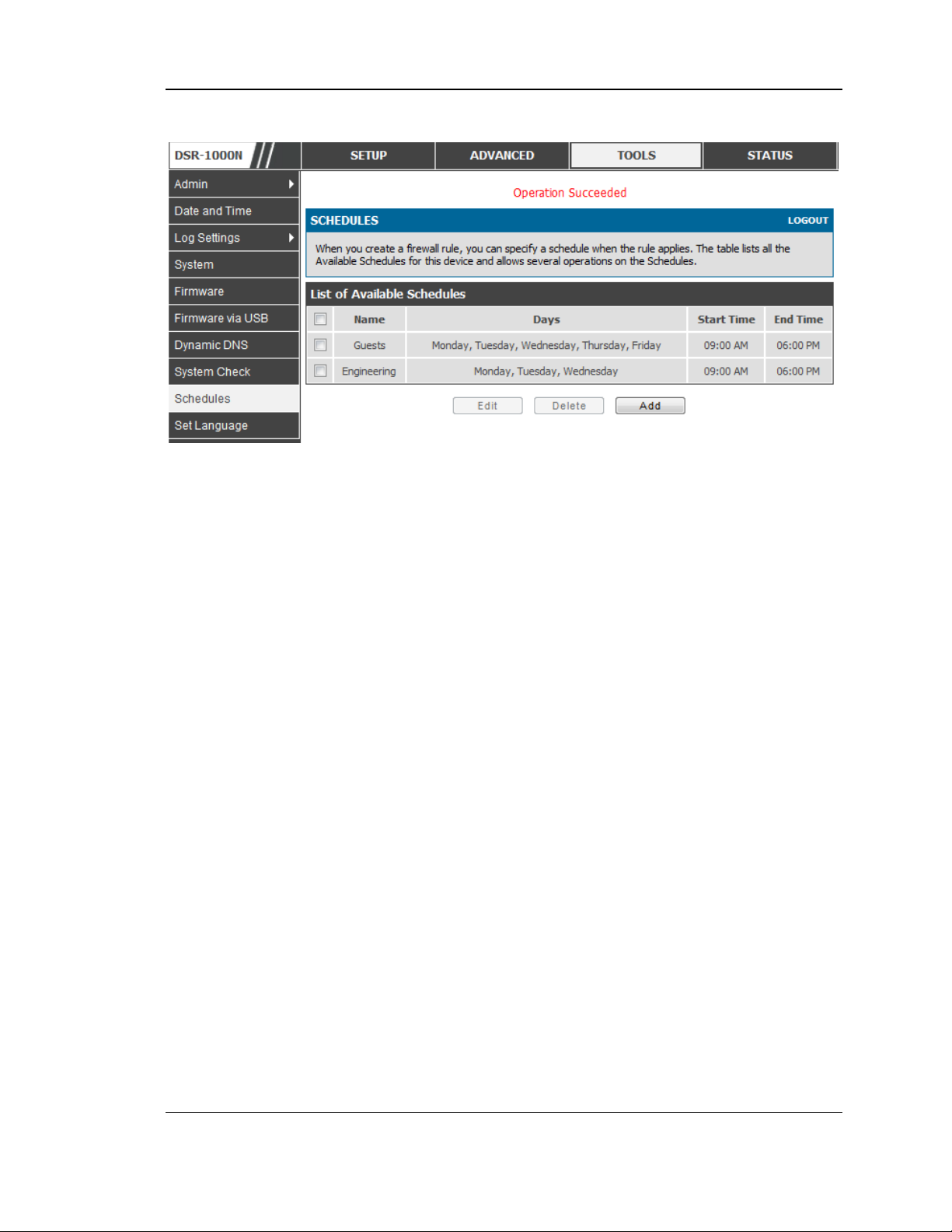
Unified Services Router User Manual
Figure 53: List of Available Sche dules to bind to a firewall rule
5.3 Configuring Firewall Rules
Advanced > Firewall Settings > Firewall Rules
All configured firewall rules on the router are displayed in the Firewall Rules list.
This list als o indicates whether the rule is enabled (active) or not, and gives a
summary of the From/To zone as well as the services or users that the rule affects.
To create a new firewall rules, follow the steps below:
1. View the existing rules in the List of Available Firewall Rules table.
2. To edit or add an outbound or inbound services rule, do the following:
To edit a rule, click the checkbox next to the rule and click Edit to re a ch t h a t rule’s
configuration page.
To add a new rule, click Add to be taken t o a new ru le’s con fig u ratio n p a g e . Once
created, the new rule is automatically added to the original table.
3. Chose the From Zone to be the source of originating traffic: either the secure LAN, public
DMZ, or insecure WAN. For an inbound rule WAN should be selected as the From Zone.
4. Choose the To Zone to be the destination of traffic covered by this rule. If the From Zone
is the WAN, the to Zone can be the public DMZ or secure LAN. Similarly if the From
Zone is the LAN, then the To Zone can be the public DMZ or insecure WAN.
5. Parameters that define the firewall rule include the following:
87
Page 90

Unified Services Router User Manual
Service: ANY means all traffic is affected by this rule. For a specific
service the drop down lis t has common services, or you can select a
custom defined service.
Action & Schedule: Select one of the 4 actions that this rule defines:
BLOCK always , ALLOW always, BLOCK by s chedule otherwise
ALLOW, or ALLOW by schedule oth erwise BLOCK. A schedule mus t
be preconfigured in order for it to be available in the dropdown lis t to
ass ign to this rule.
Source & Destination users: For each relevant category, select the users
to which the rule applies:
Any (all users)
Single Address (enter an IP addres s)
Address Range (enter the appropriate IP addres s range)
Log: traffic that is filtered by this rule can be log ged; this requires
configuring th e ro u t er’s lo g g ing f eatu re s ep a rately .
QoS Priority: Outbound rules (where To Zone = insecure W AN only)
can have the traffic marked with a QoS priority tag. Select a priority
level:
Normal-Service: ToS=0 (lowes t QoS)
Minimize-Cost: ToS=1
Maximize-Reliability: ToS=2
Maximize-Throughput: ToS=4
Minimize-Delay: ToS=8 (highes t QoS)
6. Inbound rules can use Destination NAT (DNAT) for managing traffic from the WAN.
Destination NAT is available when the To Zone = DMZ or secure LAN.
With an inbound allow rule you can enter the internal server addres s
that is hos ting the selected service.
You can enable port forwarding for an incoming service specific rule
(From Zone = WAN) by selecting the appropriate ch eckbox. This will
allow the s elected s ervice traffic from the internet to reach the
appropriate LAN port via a port forwarding rule.
Trans late Port Number: With port forwarding, the incoming traffic to
be forwarded to the port number entered here.
88
Page 91

Unified Services Router User Manual
External IP address: The rule can be bound to a specific WAN interface
by selecting either the primary W AN or con figurable port WAN as the
source IP address for incoming traffic.
This router supports multi-NAT and so the External IP address does not necessarily
have to be the WAN address . On a single WAN interface, multiple public IP
addresses are supported. If your ISP assigns you more than one public IP address ,
one of thes e can be used as your p rimary IP address on the WAN port , and the
others can be assigned to servers on the LA N or DMZ. In this way the LAN/DMZ
server can be accessed from the internet by its alias ed public IP address .
7. Outbound rules can use Source NAT (SNAT) in order to map (bind) all LAN/DMZ traffic
matching the rule parameters to a specific WAN interface or external IP address (usually
provided by your ISP).
Once the new or modified rule parameters are saved, it appears in the master list of
firewall rules . To enable or disable a rule, click the checkbox next to the rule in the
lis t of firewall rules and choose Enable or Dis able.
The router applies firewall rules in the order listed. As a general rule, you should
move the strictest rules (those with the most specific services or address es ) to the
top of the list. To reorder rules, click the checkbox next to a rule and click up or
down.
89
Page 92
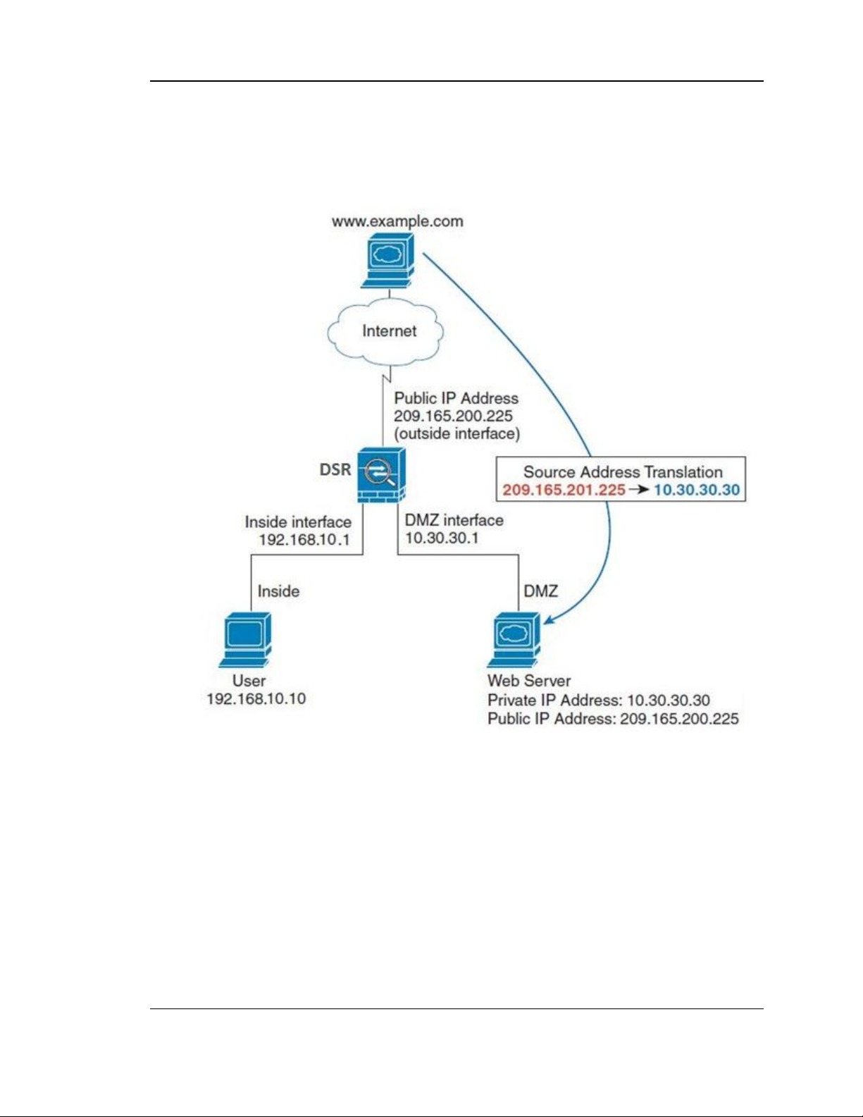
Unified Services Router User Manual
Figure 54: Example where an outbound SNAT rule is used to map an
exte rnal IP address (209.156.200.225) to a private DMZ IP
addre ss (10.30.30.30)
90
Page 93
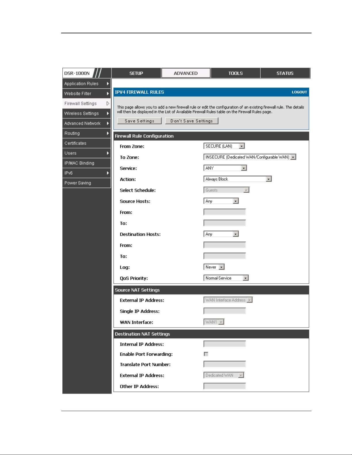
Unified Services Router User Manual
Figure 55: The firewall rule configuration page allows you to define the
To/From zone , service , action, schedule s, and specify
source/destination IP addresses as needed.
91
Page 94
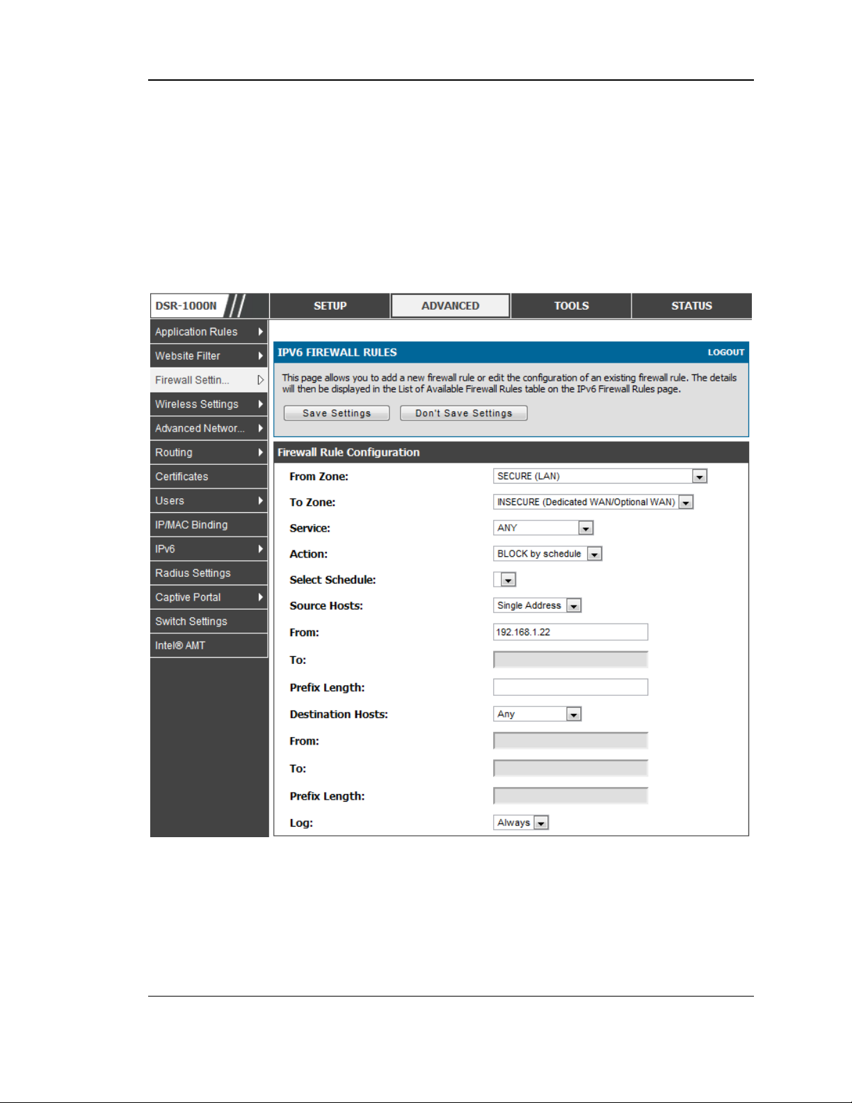
Unified Services Router User Manual
5.4 Configuring IPv6 Firewall Rules
Advanced > Firewall Settings > IPv6 Firewall Rules
All configured IPv6 firewall rules on the router are displayed in the Firewall Rules
lis t. This list als o indicates whether the rule is enabled (active) or not, and gives a
summary of the From/To zone as well as the s ervices or users that the rule affects .
Figure 56: The IPv6 firewall rule configuratio n page allows you to de fine
the To/From zone, service, action, s che dules , and specify
source/destination IP addre sses as nee ded.
92
Page 95
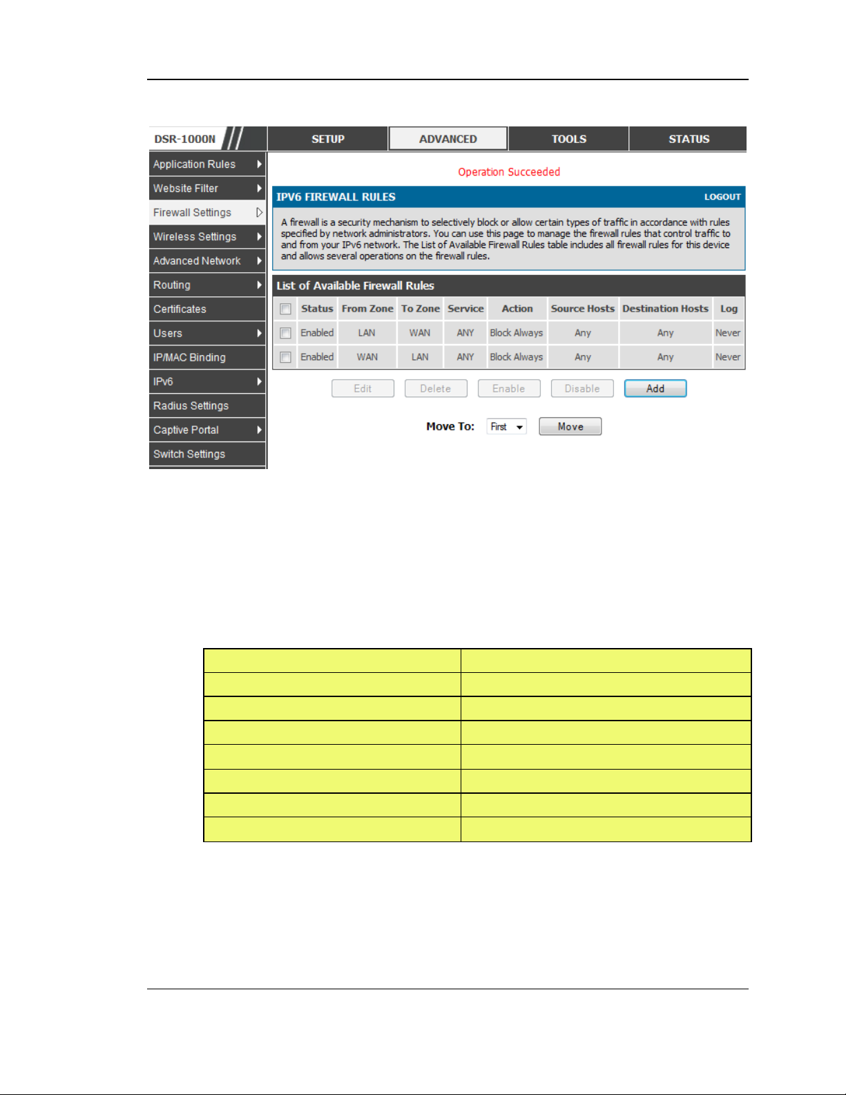
Unified Services Router User Manual
Parameter
Value
From Zone
Insecure (WAN1/WAN2/WAN3)
To Zone
Public (DMZ)
Service
HTTP
Action
ALLOW always
Send to Local Server (DNAT IP)
192.168.5.2 (w eb server IP address)
Destination Users
Any
Log
Never
Figure 57: List of Available IPv6 Firewall Rules
5.4.1 Firewall Rule Configuration Examples
Example 1: Allow inbound HTTP traffic to the DMZ
Situation: You hos t a public web server on your local DMZ network. You want to
allow inbound HTTP requests from any outside IP address to the IP address of your
web server at any time of day.
Solution: Create an inbound rule as follows.
Example 2: Allow videoconferencing from range of outs ide IP address es
Situation: You want to allow incoming videoconferencing to be initiated from a
res tricted range of outside IP addres ses (132.177.88.2 - 132.177.88.254), from a
branch office.
93
Page 96

Unified Services Router User Manual
Parameter
Value
From Zone
Insecure (WAN1/WAN2/WAN3)
To Zone
Secure (LAN)
Service
CU-SEEME:UDP
Action
ALLOW always
Send to Local Server (DNAT IP)
192.168.10.11
Destination Users
Address Range
From
132.177.88.2
To
134.177.88.254
Enable Port Forwarding
Yes (enabled)
Parameter
Value
From Zone
Insecure (WAN1/WAN2/WAN3)
To Zone
Public (DMZ)
Service
HTTP
Action
ALLOW always
Send to Local Server (DNAT IP)
192.168.12.222 ( w eb server local IP address)
Destination Users
Single Address
Solution: Create an inbound ru le as follows. In the example, CUSeeMe (the video
conference service us ed) connections are allowed only from a specified range of
external IP addres ses.
Example 3: Multi-NAT configuration
Situation: You want to configure multi-NAT to support multiple public IP
addresses on one WAN port interface.
Solution: Create an inbound rule that configures the firewall to hos t an additional
public IP address . As sociate this address with a web s erver on the DMZ. If you
arrange with your ISP to have more than one public IP address for your use, you can
use the additional public IP addresses to map to s ervers on your LAN. One of these
public IP addresses is used as the primary IP address of the router. This address is
used to provide Internet access to your LAN PCs through NAT. The other addresses
are available to map to your DMZ s ervers .
The followin g address ing scheme is used to illustrate this procedure:
WAN IP address : 10.1.0.118
LAN IP address : 192.168.10.1; subnet 255.255.255.0
Web server host in the DMZ, IP ad dress: 192.168.12.222
Access to Web server: (simulated) public IP address 10.1.0.52
94
Page 97

Unified Services Router User Manual
From
10.1.0.52
WAN Users
Any
Log
Never
E
x
a
m
p
le 4: Bloc
Example 4: Block traffic by schedule if generated from s pecific range of machines
Use Cas e: Block all HTTP traffic on the weekends if the reques t originates from a
specific group of machines in the LAN having a known range of IP address es , and
anyone coming in through the Network from the WAN (i.e. all remote users).
Configuration:
1. Setup a schedule:
To setup a schedule that affects traffic on weekends only, navigate to Security:
Schedule, and n a me the s ch e d u le “ W e e kend ”
De fin e “we e kend” to mean 12 am Satu rday morn ing to 12 a m Mon d a y mo rnin g
– all day Saturday & Sunday
In the Scheduled days b ox, check that you want the schedule to be active for
“s p e c ific d a y s ”. Se le c t “Sat urd a y ” and “Su n d ay ”
In th e sched u le d time o f d a y , s ele c t “a ll d a y ” – this will apply the schedule
between 12 am to 11:59 pm of the selected day.
Click apply – now sch e du le “ W eeke n d ” is olates all day Saturday and Sunday
from the res t of the week.
95
Page 98
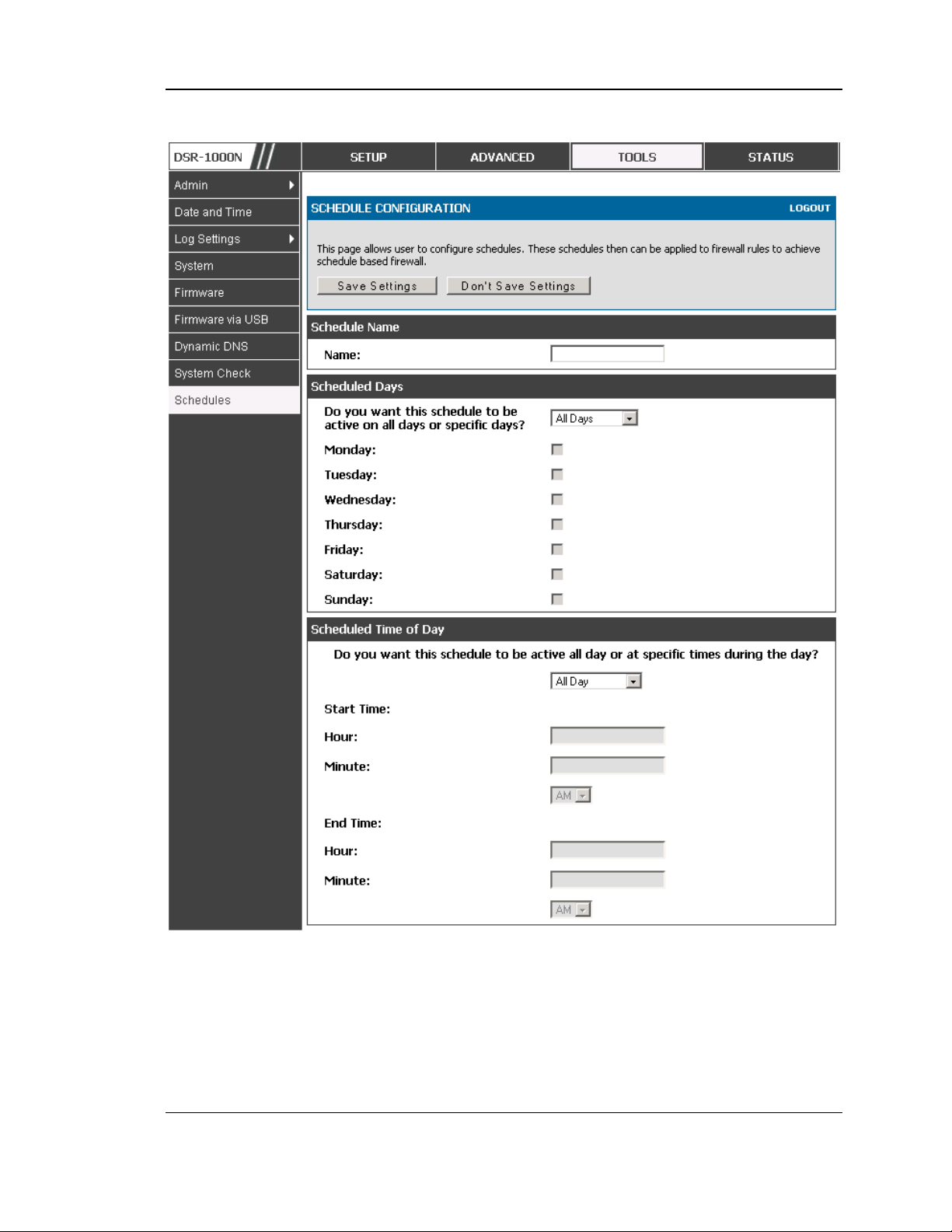
Unified Services Router User Manual
Figure 58: Schedule configuration for the above e xample.
2. Since we are trying to block HTTP requests, it is a service with To Zone: Insecure
(WAN1/WAN2/WAN3) that is to be blocked according to schedule “Weekend”.
96
Page 99

Unified Services Router User Manual
3. Select the Action to “Block by Schedule, otherwise allow”. This will take a predefined
schedule and make sure the rule is a blocking rule during the defined dates/times. All
other times outside the schedule will not be affected by this firewall blocking rule
4. As we defined our schedule in schedule “Weekend”, this is available in the dropdown
menu
5. We want to block the IP range assigned to the marketing group. Let’s say they have IP
192.168.10.20 to 192.168.10.30. On the Source Users dropdown, select Address Range
and add this IP range as the from and To IP addresses.
6. We want to block all HTTP traffic to any services going to the insecure zone. The
Destination Users dropdown should be “any”.
7. We don’t need to change default QoS priority or Logging (unless desired) – clicking apply
will add this firewall rule to the list of firewall rules.
8. The last step is to enable this firewall rule. Select the rule, and click “enable” below the
list to make sure the firewall rule is active
5.5 Security on Custom Services
Advanced > Firewall Settings > Custom Services
Cus tom services can be defined to add to the lis t of services available during firewall
rule configuration. While common services have known TCP/UDP/ICMP ports for
traffic, many cus tom or uncommon applications exist in the LAN or W AN. In the
custom service configuration menu you can define a ran ge of ports and identify the
traffic type (TCP/UDP/ICMP) for this service. Once defined, the new s ervice will
appear in the services lis t of the firewall rules configuration menu.
97
Page 100
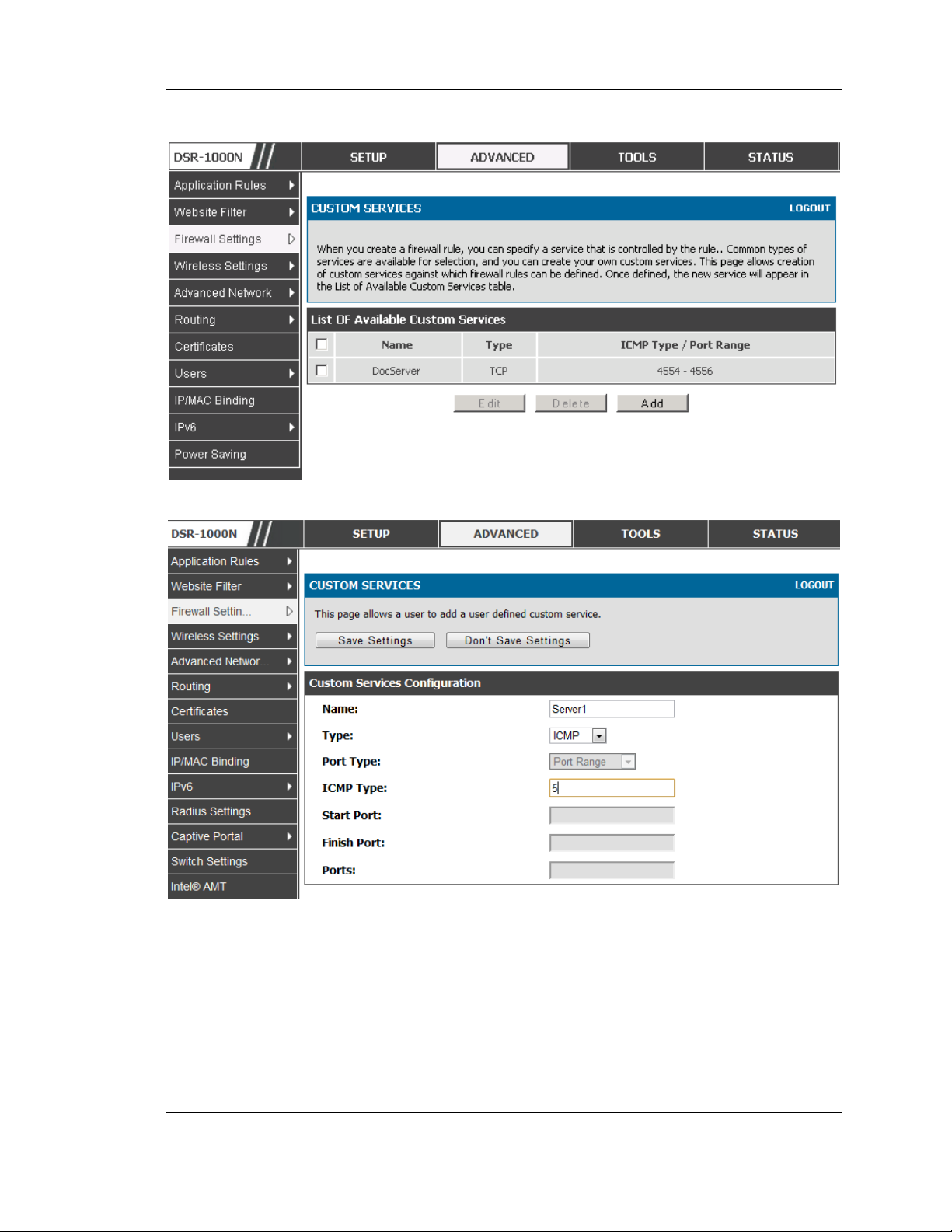
Unified Services Router User Manual
Figure 59: List of user defined se rvices.
Figure 60: Custom Services configuration
Created services are available as options for firewall rule configuration.
Name: Name of the service for identification and management purposes .
Type: The layer 3 Protocol that the s ervice uses . (TCP, UDP, BOTH, ICMP or
ICMPv6)
Port Type: This fields allows to select Port Range or Multiple Po rts
ICMP Type: This field is enabled when the layer 3 protocol (in the Type field) is
selected as ICMP or ICMPv6. The ICMP type is a numeric value that can range
between 0 and 40, while for ICMPv6 the type ranges from 1 to 255. For a list of
98
 Loading...