

Page 1

DSL-560I
ADSL Router
User’s Guide
(September 2002)
651SL560I015
Page 2

DSL-560I ADSL Router User’s Guide
Wichtige Sicherheitshinweise
1. Bitte lesen Sie sich diese Hinweise sorgfältig durch.
2. Heben Sie diese Anleitung für den spätern Gebrauch auf.
3. Vor jedem Reinigen ist das Gerät vom Stromnetz zu trennen. Vervenden Sie keine Flüssig- oder Aerosolreiniger. Am
besten dient ein angefeuchtetes Tuch zur Reinigung.
4. Um eine Beschädigung des Gerätes zu vermeiden sollten Sie nur Zubehörteile verwenden, die vom Hersteller zugelassen
sind.
5. Das Gerät is vor Feuchtigkeit zu schützen.
6. Bei der Aufstellung des Gerätes ist auf sichern Stand zu achten. Ein Kippen oder Fallen könnte Verletzungen
hervorrufen. Verwenden Sie nur sichere Standorte und beachten Sie die Aufstellhinweise des Herstellers.
7. Die Belüftungsöffnungen dienen zur Luftzirkulation die das Gerät vor Überhitzung schützt. Sorgen Sie dafür, daß diese
Öffnungen nicht abgedeckt werden.
8. Beachten Sie beim Anschluß an das Stromnetz die Anschlußwerte.
9. Die Netzanschlußsteckdose muß aus Gründen der elektrischen Sicherheit einen Schutzleiterkontakt haben.
10. Verlegen Sie die Netzanschlußleitung so, daß niemand darüber fallen kann. Es sollete auch nichts auf der Leitung
abgestellt werden.
11. Alle Hinweise und Warnungen die sich am Geräten befinden sind zu beachten.
12. Wird das Gerät über einen längeren Zeitraum nicht benutzt, sollten Sie es vom Stromnetz trennen. Somit wird im Falle
einer Überspannung eine Beschädigung vermieden.
13. Durch die Lüftungsöffnungen dürfen niemals Gegenstände oder Flüssigkeiten in das Gerät gelangen. Dies könnte einen
Brand bzw. Elektrischen Schlag auslösen.
14. Öffnen Sie niemals das Gerät. Das Gerät darf aus Gründen der elektrischen Sicherheit nur von authorisiertem
Servicepersonal geöffnet werden.
15. Wenn folgende Situationen auftreten ist das Gerät vom Stromnetz zu trennen und von einer qualifizierten Servicestelle zu
überprüfen:
a – Netzkabel oder Netzstecker sint beschädigt.
b – Flüssigkeit ist in das Gerät eingedrungen.
c – Das Gerät war Feuchtigkeit ausgesetzt.
d – Wenn das Gerät nicht der Bedienungsanleitung ensprechend funktioniert oder Sie mit Hilfe dieser Anleitung keine
Verbesserung erzielen.
e – Das Gerät ist gefallen und/oder das Gehäuse ist beschädigt.
f – Wenn das Gerät deutliche Anzeichen eines Defektes aufweist.
16. Bei Reparaturen dürfen nur Orginalersatzteile bzw. den Orginalteilen entsprechende Teile verwendet werden. Der
Einsatz von ungeeigneten Ersatzteilen kann eine weitere Beschädigung hervorrufen.
17. Wenden Sie sich mit allen Fragen die Service und Repartur betreffen an Ihren Servicepartner. Somit stellen Sie die
Betriebssicherheit des Gerätes sicher.
18. Zum Netzanschluß dieses Gerätes ist eine geprüfte Leitung zu verwenden, Für einen Nennstrom bis 6A und einem
Gerätegewicht großer 3kg ist eine Leitung nicht leichter als H05VV-F, 3G, 0.75mm2 einzusetzen
Limited Warranty
Hardware:
D-LINK WARRANTS EACH OF ITS HARDWARE PRODUCTS TO BE FREE FROM DEFECTS IN WORKMANSHIP AND
MATERIALS UNDER NORMAL USE AND SERVICE FOR A PERIOD COMMENCING ON THE DATE OF PURCHASE FROM
D-LINK OR ITS AUTHORIZED RESELLER AND EXTENDING FOR THE LENGTH OF TIME STIPULATED BY THE
AUTHORIZED RESELLER OR D-LINK BRANCH OFFICE NEAREST TO THE PLACE OF PURCHASE.
THIS WARRANTY APPLIES ON THE CONDITION THAT THE PRODUCT REGISTRATION CARD IS FILLED OUT AND
RETURNED TO A D-LINK OFFICE WITHIN NIN ETY (90) D AYS O F PURCHASE. A LI ST OF D-LIN K OFF ICES IS PRO VIDED AT
THE BACK OF THIS MANUAL, TOGETHER WITH A COPY OF THE REGISTRATION CARD.
IF THE PRODUCT PROVES DEFECTIVE WITHIN THE APPLICABLE WARRANTY PERIOD, D-LINK WILL PROVIDE REPAIR
OR REPLACEMENT OF THE PRODUCT. D-LINK SHALL HAVE T HE SOLE D ISCR ETION WHETH ER TO REP AIR O R REPLAC E,
AND REPLACEMENT PRODUCT MAY BE NEW OR RECONDITIONED. REPLACEMENT PRODUCT SHALL BE OF
EQUIVALENT OR BETTER SPECIFICATIONS, RELATIVE TO THE DEFECTIVE PRODUCT, BUT NEED NO T BE IDENTICAL.
ANY PRODUCT OR PART REPAIRED BY D-LINK PURSUANT TO THIS WARRANT Y SHALL H AVE A WARR ANT Y PERIOD OF
NOT LESS THAN 90 DAYS, FROM DATE OF SUCH RE PAIR, IRRESPECTIVE OF ANY EARLIER EXPIRATION OF ORIGINAL
WARRANTY PERIOD. WHEN D-LINK PROVIDES REPLACEMENT, THEN THE DEFECTIVE PRODUCT BECOMES THE
PROPERTY OF D-LINK.
ii
Page 3

DSL-560I ADSL Router User’s Guide
WARRANTY SERVICE MAY BE OBTAINED BY CONTACTING A D-L INK OFFICE WITHIN THE APPLICABLE WARRANTY
PERIOD, AND REQUESTING A RETURN MATERIAL AUTHORIZATION (RMA) NUMBER. IF A REGISTRATION CARD FOR
THE PRODUCT IN QUESTION HAS NOT BEEN RETURNED TO D-LINK, THEN A PROOF OF PURCHASE (SUCH AS A COPY OF
THE DATED PURCHASE INVOICE) MUST BE PROVIDED. IF PURCHASER'S CIRCUMSTANCES REQUIRE SPECIAL
HANDLING OF WARRANTY CORRECTION, THEN AT THE TIME OF REQUESTI NG RMA NUMBER, PURCH ASER MAY ALSO
PROPOSE SPECIAL PROCEDURE AS MAY BE SUITABLE TO THE CASE.
AFTER AN RMA NUMBER IS ISSUED, THE DEFECTIV E PRODUCT MUST BE PAC KAGED SECURELY IN THE ORIGINAL OR
OTHER SUITABLE SHIPPING PACKAGE TO ENSURE THAT IT WILL NOT BE DAMAGED IN TRANSIT, AND THE RMA
NUMBER MUST BE PROMINENTLY MARKED ON THE OUTS IDE OF THE PACKAGE. TH E PACKAGE MUST BE MAILED OR
OTHERWISE SHIPPED TO D-LINK WITH ALL C OSTS OF MAILING/SHIPPING/ INSURANCE PREPAID. D-LINK SHA LL NEVER
BE RESPONSIBLE FOR ANY SOFTWARE, FIRMWARE, INFORMA TION, OR MEMO RY DATA OF P URCHASER C ONTAINE D IN,
STORED ON, OR INTEGRATED WITH ANY PRODUCT RETURNED TO D-LINK PURSUANT TO THIS WARRANTY.
ANY PACKAGE RETURNED TO D-LINK WITHOUT AN RMA NUMBER WILL BE REJECTED AND SHIPPED BACK TO
PURCHASER AT PURCHASER'S EXPENSE, AND D-LINK RES ERVES THE RI GHT IN SUCH A CASE TO LEVY A RE ASONAB LE
HANDLING CHARGE IN ADDITION MAILING OR SHIPPING COSTS.
Software:
WARRANTY SERVICE FOR SOFTWARE PRODUCTS MAY BE OBTAINED BY CONTACTIN G A D-LINK OFFICE WI THIN THE
APPLICABLE WARRANTY PERIOD. A LIST OF D-LINK OFFICES IS PROVIDED AT THE BACK OF THIS MANUAL,
TOGETHER WITH A COPY OF THE REGISTRATION CARD. IF A REGISTRATION CARD FOR THE PRODUCT IN QUESTION
HAS NOT BEEN RETURNED TO A D-LINK OFFICE, THEN A PROOF OF PURC HASE (SUCH AS A COPY OF THE DATED
PURCHASE INVOICE) MUST BE PROVIDED WHEN REQUESTING WARRANTY SERVICE. THE TERM "PURCHASE" IN THIS
SOFTWARE WARRANTY REFERS TO THE PURCHASE TRANSACTION AND RESULTING LICENSE TO USE SUCH
SOFTWARE.
D-LINK WARRANTS THAT ITS SOFTWARE PRODUCTS WILL PERFORM IN SUBSTANTIAL CONFORMANCE WITH THE
APPLICABLE PRODUCT DOCUMENTATION PROVIDED BY D-LINK WITH SUCH SOFTWARE PR ODUCT, FOR A PERIOD OF
NINETY (90) DAYS FROM THE DATE OF PURCHASE FROM D-LINK OR ITS AUTHORIZED RESELLER. D-LINK WARRANTS
THE MAGNETIC MEDIA, ON WHICH D-LINK PROVIDES ITS S OFTWAR E PRODUCT, AGAINS T FAILURE DURING THE SAME
WARRANTY PERIOD. THIS WARRANTY APPLIES TO PURCHASED SOFTWARE, AND TO REPLACEMENT SOFTWARE
PROVIDED BY D-LINK PURSUANT TO THIS WARRANTY, BUT SHALL NOT APPLY T O ANY UPDATE OR REPLACEMENT
WHICH MAY BE PROVIDED FOR DOWNLOAD VIA THE INTER NET, OR TO ANY UPDATE WHICH MAY OTHERWISE BE
PROVIDED FREE OF CHARGE.
D-LINK'S SOLE OBLIGATION UNDER THIS SOFTWARE WARRANTY SHALL BE TO REPLACE ANY DEFEC TIVE SOFTWARE
PRODUCT WITH PRODUCT WHICH SUBSTANTIALLY CONFORMS TO D-L INK'S APPLICABLE P RODUCT DOCU MENTATION .
PURCHASER ASSUMES RESPONSIBILITY FOR THE SELECTION OF APPROPRIATE APPLICATION AND SYSTEM/PLATFORM
SOFTWARE AND ASSOCIATED REFERENCE MATERIALS. D-LINK MAKES NO WARRANTY THAT ITS SOFTWARE
PRODUCTS WILL WORK IN COMBINATION WITH ANY HARDWARE, OR ANY APPLICATION OR SYSTEM/PLATFORM
SOFTWARE PRODUCT PROVIDED BY ANY THIRD PARTY, EXCEPTING ONLY SUCH PRODUCTS AS ARE EXPRESSLY
REPRESENTED, IN D-LINK'S APPLICABLE PRODUCT DOCUMENTAT ION AS BEING COMPATIBLE. D-LINK'S OB LIGATION
UNDER THIS WARRANTY SHALL BE A REASONABLE E FFORT TO PROVIDE COMPATIBILITY, BUT D- LINK SHALL HAVE
NO OBLIGATION TO PROVIDE COMPATIBILITY WHEN THERE IS FAULT IN THE THIRD-PARTY HARDWARE OR
SOFTWARE. D-LINK MAKES NO WARRANTY THAT OPERATION OF ITS SOFTWARE PRODUCTS WILL BE
UNINTERRUPTED OR ABSOLUTELY ERROR-FREE, AND NO WARRANTY THAT ALL DEFECTS IN THE SOFTWARE
PRODUCT, WITHIN OR WITHOUT THE SCOPE OF D-LINK'S APPLICABLE PRODUCT DOCUMENTATION, WILL BE
CORRECTED.
D-Link Offices for Registration and Warranty Service
THE PRODUCT'S REGISTRATION CARD, PROVIDED AT THE BACK OF THIS MANUAL, MUST BE SENT TO A D-LINK OFFICE.
TO OBTAIN AN RMA NUMBER FOR WARRANTY SERVICE AS TO A HARDWA RE PRODUCT, OR TO OBTAIN WARRANTY
SERVICE AS TO A SOFTWARE PRODUCT, CONTACT THE D-LINK OFFICE NEAREST YOU. AN
ADDRESS/TELEPHONE/FAX/E-MAIL/WEB SITE LIST OF D-LINK OFFICES IS PROVIDED IN THE BACK OF THIS MANUAL.
LIMITATION OF WARRANTIES
IF THE D-LINK PRODUCT DOES NOT OPERATE AS WARRANTE D ABOVE, THE CUSTOMER'S S OLE REMEDY S HALL BE, AT
D-LINK'S OPTION, REPAIR OR REPLACEMENT. THE FOREGOING WARRANTIES AND REMEDIES ARE EXCLUSIVE AND
ARE IN LIEU OF ALL OTHER WARRANTIES, EXPRESSED OR IMPLIED, EITHER IN FACT OR BY OPERATION OF LAW,
STATUTORY OR OTHERWISE, INCLUDING WARRANTIES OF MERCHANTABILITY AND FITNESS FOR A PARTICULAR
PURPOSE. D-LINK NEITHER ASSUMES NOR AUTHORIZES ANY OTHER PERSON TO ASSUME FOR IT ANY OTHER
LIABILITY IN CONNECTION WITH THE SALE, INSTALLATION MAINTENANCE OR USE OF D-LINK'S PRODUCTS
D-LINK SHALL NOT BE LIABLE UNDER THIS WARRANTY IF ITS TESTING AND EXAMINATION DISCLOSE THAT THE
ALLEGED DEFECT IN THE PRODUCT DOES NOT EXIST OR WA S CAUSED BY THE CUSTOMER' S OR ANY THIRD PERSON'S
MISUSE, NEGLECT, IMPROPER INSTALLATIO N OR TESTING, UNAUTHORIZED ATTEMPTS TO REPAIR, OR ANY OTHER
CAUSE BEYOND THE RANGE OF THE INTENDED USE, OR BY ACCIDENT, FIRE, LIGHTNING OR OTHER HAZARD.
iii
Page 4

DSL-560I ADSL Router User’s Guide
LIMITATION OF LIABILITY
IN NO EVENT WILL D-LINK BE LIABLE FOR ANY DAMAG ES, INCLUDING LOSS OF DATA, LOSS OF PROFITS, COST OF
COVER OR OTHER INCIDENTAL, CONSEQUENTIAL OR INDIRECT DAMAGES ARISING OUT THE INSTALLATION,
MAINTENANCE, USE, PERFORMANCE, FAILURE OR INTERRUPTION OF A D- LINK PRODUCT, HOWEVER CAUSED AND
ON ANY THEORY OF LIABILITY. THIS LIMITATION WILL APPLY EVEN IF D-LINK HAS BEEN ADVISED OF THE
POSSIBILITY OF SUCH DAMAGE.
IF YOU PURCHASED A D-LINK PRODUCT IN THE UNITED STATES, SOM E STATES DO NOT ALLOW THE LIMITATIO N OR
EXCLUSION OF LIABILITY FOR INCIDENTAL OR CONSEQUENTIA L DAMAGES, SO THE ABOVE LIMITATION MAY NOT
APPLY TO YOU.
Trademarks
Copyright 2000 D-Link Corporati o n.
Contents subject to change without prior notice.
D-Link is a registered trademark of D-Link Corporation/D-Link Systems, Inc.
All other trademarks belong to their respective proprietors.
Copyright Statement
No part of this publication may be reproduced in any form or by any means or used to make any
derivative such as translation, transformation, or adaptation without permission from D-Link
Corporation/D-Link Systems Inc., as stipulated by the United States Copyright Act of 1976
CE Mark Warning
This is a Class B product. In a domestic environment, this product may cause radio interference in
which case the user may be required to take adequate measures.
iv
Page 5

TABLE OF CONTENTS
ABOUT THIS USER’S GUIDE................................................................................. VII
Guide Overview............................................................................................................................................ vii
Before You Start ...............................................................................................................................................vii
Requirements ....................................................................................................................................................vii
Web Browser................................................................................................................................................viii
Ethernet Port (NIC Adapter)........................................................................................................................ viii
About Bridged Ethernet Connections (RFC 1483) ......................................................................................viii
About IPoA Connections (RFC 1577)...........................................................................................................ix
Additional PVC Settings................................................................................................................................ ix
Packing List.......................................................................................................................................................... ix
INTRODUCTION........................................................................................................ 1
What is ADSL?............................................................................................................................................... 1
Router Description and Operation...................................................................................................................... 1
Router Features..................................................................................................................................................... 2
Front Panel.......................................................................................................................................................... 3
Rear Panel........................................................................................................................................................... 4
LED Indicators.................................................................................................................................................... 5
HARDWARE INSTALLATION................................................................................... 7
Connect ADSL Line.............................................................................................................................................. 7
Compuer to Router Connection........................................................................................................................... 7
Connect Ethernet LAN to Router........................................................................................................................ 8
Hub or Switch to Router Connection.................................................................................................................. 8
Power On Router .................................................................................................................................................. 9
CONFIGURING THE ROUTER FOR THE FIRST TIME ...........................................10
Configuring IP Settings on Your Computer...................................................................................................... 10
Access the Configuration Manager................................................................................................................... 17
Configure the Router......................................................................................................................................... 17
WEB-BASED MANAGEMENT .................................................................................20
Accessing the Web Manager............................................................................................................................. 20
Folders and Menus........................................................................................................................................ 21
BASIC .......................................................................................................................21
Router Configuration ......................................................................................................................................... 21
Configuring the WAN Connection ................................................................................................................... 22
Additional Virtual Connections (PVCs) ........................................................................................................... 23
Page 6

Configuring LAN IP Settings............................................................................................................................ 26
Access Control.............................................................................................................................................. 27
ADSL Link Status......................................................................................................................................... 29
Routing Setup................................................................................................................................................ 30
Save and Reboot............................................................................................................................................ 30
Erase and Reboot .......................................................................................................................................... 31
ADVANCED..............................................................................................................32
ADSL Mode.................................................................................................................................................. 33
Redirect Port ................................................................................................................................................. 33
NAT .............................................................................................................................................................. 34
DHCP Server................................................................................................................................................. 35
SNMP............................................................................................................................................................ 36
Interface ........................................................................................................................................................ 37
VCC .............................................................................................................................................................. 39
PPPoE ........................................................................................................................................................... 41
PPPoA........................................................................................................................................................... 42
IGMP Proxy.................................................................................................................................................. 42
Bridge............................................................................................................................................................ 43
Spanning Tree............................................................................................................................................... 44
Filter.............................................................................................................................................................. 46
Interface ........................................................................................................................................................ 47
TCP-IP .......................................................................................................................................................... 48
DHCP-Lease................................................................................................................................................. 49
AAL5 ............................................................................................................................................................ 49
SNDCP.......................................................................................................................................................... 50
Loopback....................................................................................................................................................... 50
Ping............................................................................................................................................................... 51
TECHNICAL SPECIFICATIONS...............................................................................52
LAN IP SETUP..........................................................................................................54
Assigning Network IP Addresses....................................................................................................................... 54
Using the Default IP Address............................................................................................................................ 54
Manual IP Address Assignment.................................................................................................................... 54
Using DHCP ................................................................................................................................................. 55
Changing the IP Address of the Router............................................................................................................. 55
IP CONCEPTS..........................................................................................................56
IP Addresses........................................................................................................................................................ 56
Subnet Mask........................................................................................................................................................ 58
MICROFILTERS AND SPLITTERS..........................................................................59
Microfilters ................................................................................................................................................... 59
Line Splitter .................................................................................................................................................. 60
Page 7

DSL-560I ADSL Ethernet Router User’s Guide
About This User’s Guide
This user’s guide provides instructions on how to install the DSL-560I ADSL Router and use it to connect a
computer or Ethernet LAN to the Internet.
If you are using a computer with a functioning Ethernet port, you can use the Quick Installation Guide to quickly
establish your ADSL connection and access the Internet.
Guide Overview
Introduction – Describes the Router and its key features. Provides an introduction to ADSL. Lists
standards to which the Router complies. Contains a packing list.
Hardware Installation – Discusses how to connect the Router to an Ethernet LAN.
Configuring the Router for the First Time – Provides information on how to configure the Router and
establish the WAN connection using the web-based manager.
Web-based Configuration – Describes how to use the web-based manager to change Router settings and
configure additional virtual connections (PVCs).
Appendix A - Technical Specifications – Lists the technical specifications of the Router, including
standards compliance.
Appendix B - Low Pass Filters – Illustrated examples of how to use low pass filters.
Before You Start
Please read and make sure you understand all the prerequisites for proper installation of your new Modem. Have
all the necessary information and equipment on hand before beginning the installation.
Installation Overview
The procedure to install the Router can be described in general terms in the following steps:
1. Gather information and equipment needed to install the device. Before you begin th e actual installation
make sure you have all the necessary information and equipment.
2. Install the hardware, that is, connect the cables (Ethernet and telephone) to the device and connect the
power adapter.
3. Check the IP settings on your computer and change them if necessary so the computer can access the
web-based software built into the Router.
4. Use the web-based management software to configure the device to suit the requirements of your ADSL
account.
Requirements
To install and use the Router you need a computer equipped with an Ethernet port (such as an Ethernet NIC) and
a web browser. You may also need to use information given to you by your ISP. This information is stored in th e
Router’s memory and used to establish the WAN connection and confirm your identity. Read the next page for
more details about these requirements.
Low Pass Filters
Since ADSL and telephone services share the same copper wiring to carry their respective signals, a filtering
mechanism may be necessary to avoid mutual interference. A low pass filter device can be installed for each
telephone that shares the line with the ADSL line. These filters are easy to install passive devices that connect to
the ADSL device and/or telephone using standard telephone cable. Ask your service provider for more
information about the use of low pass filters with your installation. Appendix B provides illustrated examples of
how to install two common styles of low pass filters.
vii
Page 8
DSL-560I ADSL Ethernet Router User’s Guide
Operating System
The DSL-560I uses a HTML-based web interface for setup and management. The web configuration manager
may be accessed using any operating system capable of running web browser software.
Web Browser
Any common web browser can be used to configure the Router by accessing its web configuration management
software. The program is designed to work best with more recently released browsers such as Microsoft Internet
Explorer® version 5.0, Netscape Navigator® version 4.7, or later versions. The web browser must have
JavaScript enabled. JavaScript is enabled by default on many browsers. Make sure JavaScript has not been
disabled by other software (such as virus protection or web user security packages) that may be running on your
computer.
Ethernet Port (NIC Adapter)
Any computer that uses the Router must be able to connect to it through the Ethernet port on the Router. This
connection is an Ethernet connection and therefore requires that your computer be equipped with an Ethernet
port as well. Nowadays, most notebook computers ar e alread y sold with the installed Ethernet adap ter. Likewise,
most fully assembled desktop computers come with an Ethernet NIC card as standard equipment. If your
computer does not have an Ethernet port, you must install an Ethernet NIC adapter before you can access the
Router. If you must install an adapter, follow the installation instructions that come with the Ethernet NIC
adapter.
Additional Software
It may be necessary to install software on your computer that enables the computer to access the Internet.
Additional software must be installed if you are using what is called a “bridged” connection. For a bridged
connection, the information needed to make and maintain the Internet connection is stored on your co mputer, not
in the Router. This type of connection is similar to the arrangement used for analog dial-up mode ms, but the
connection speed is much faster. Various terms are to describe a bridged ADSL connection including the term
“RFC 1483 Bridge” which is also used in this guide.
If your ADSL service is delivered through a PPP (Point to Point Protocol) connection, the information needed to
establish and maintain the Internet connection can be stored in the Router. In this case, it is not necessary to
install any PPP software on your computer.
Account Information (User Name and Password)
Most users will need to supply a user name and password used to access the service provider’s network (and
ultimately, the Internet). This information is stored either in the Router’s memory or on your computer
depending on the type of ADSL connection you have.
ACCOUNT INFORMATION (PPP Connections Only)
User Name:
Password:
About Bridged Ethernet Connections (RFC 1483)
Using this method, the DSL-560I acts as a transparent bridge, and is invisible to other devices on both the WAN
and LAN side of the bridge. It is therefore necessary to provide some means of acquiring global IP settings for
your account.
All connections to the Internet require a unique global IP address. For bridged conn ections, the glob al IP settings
must reside in a TCP/IP enabled device on the LAN side of the bridge, such as a PC, server or firewall hardware.
The IP address can be assigned in a number of ways. Your network service provider will give you in structions
about any additional connection software or NIC configuration that may be required.
viii
Page 9

DSL-560I ADSL Ethernet Router User’s Guide
About IPoA Connections (RFC 1577)
IP over ATM connections may require global IP settings for the device. Your service provider will give you IP
settings information if needed. Some IPoA connections function like peer-to-peer connections and therefore do
not require IP settings on the WAN interface.
Additional PVC Settings
If you are using multiple virtual connections it will be necessary to provide additional VPI and VCI values for
the device. These numbers define a unique route used on the ATM backbone of the WAN. Chapter 5 contains
instruction on how to set up additional PVCs for accounts using more than one virtual connection.
Packing List
Open the shipping carton and carefully remove all items. In addition to this User's Guide, ascertain that you have:
1. One DSL-560I ADSL Ethernet Router
2. One User’s Guide
3. One twisted-pair telephone cable used for ADSL connection
4. One straight-through Ethernet cable
5. One AC power adapter suitable for your electric service
ix
Page 10

Page 11

DSL-560I ADSL Router User’s Guide
Introduction
This section provides a brief description of the Router, its associated technologies and a list of Router features.
What is ADSL?
Asymmetric Digital Subscriber Line (ADSL) is an access technology that utilizes ordinary copper telephone
lines to enable broadband high-speed digital data transmission and interactive multimedia applications for
business and residential customers. For ADSL services, it is not necessary to use expensive new cabling or
condition the line in any way.
ADSL greatly increases the signal carrying capacity of copper telephone lines withou t interfering with regular
telephone services. For the ADSL user, this means faster downloads and more reliable connectivity. ADSL
devices make it possible to enjoy benefits such as high-speed Internet access without experiencing any loss of
quality or disruption of voice/fax telephone capabilities.
ADSL provides a dedicated service over a single telephone line operating at speeds of up to 8 Mbps downstream
and up to 640 Kbps upstream, depending on local telephone line conditions. A secure point-to-point conn ection
is established between the user and the central office of the service provider.
D-Link ADSL devices incorporate the recommendations of the ADSL Forum regarding framing, data format,
and upper layer protocols.
Router Description and Operation
The DSL-560I ADSL Router is designed to provide a simple, cost-effective and secure ADSL Internet
connection for your small- to medium-sized private network. The DSL-560I combines the benefits of high-speed
ADSL connection technology and TCP/IP routing with a conventional Ethernet interface in one compact and
convenient package. ADSL connection techno logy enables many interactive multi-media applications such as
video conferencing and collaborative computing.
The Router is easy to install and use. The DSL-560I connects to an Ethernet LAN via a standard Ethernet
100BASE-T interface using RJ-45 connectors. The ADSL connection is made using ordinary twisted-pair
telephone line with standard RJ-11 connectors. This arrangement means that several PCs can be networked and
connected to the Internet using a single WAN interface and IP address.
The Router supports transparent bridging and can be used for IP packet routing over the Internet. Cost saving
features of the Router such as NAT (Network Address Translator) and DHCP (Dynamic Host Configuration
Protocol) improve administration efficiency and improve security. The advanced security enhancements, packet
filtering and port redirection, can help protect your network from potentially devastating intrusions by malicious
agents from outside your network.
1
Page 12

DSL-560I ADSL Router User’s Guide
Router Features
The DSL-560I ADSL Ethernet Router utilizes the latest ADSL enhancements to provide a reliable Internet portal
suitable for most small to medium sized offices. DSL-560I advantages include:
• PPP (Point-to-Point Protocol) Security The DSL-560I ADSL Router supports PAP (Password
Authentication Protocol) and CHAP (Challenge Handshake Authentication Protocol) for PPP connections.
• DHCP Support Dynamic Host Configuration Protocol automatically and dynamically assigns al LAN IP
settings to each host on your n etwork. This eli minates the need to reconfigure ever y host when ever ch anges
in network topology occur.
• Network Address Translation (NAT) For small office environments, the DSL-560I allows multiple users
on the LAN to access the Internet concurrently through a single Internet account. This provides Internet
access to everyone in the office for the price of a single user.
NAT improves network security in effect by hiding the private network behind one global and visible IP
address. NAT address mapping can also be used to link two IP domains via a LAN-to-LAN connection.
• TCP/IP (Transfer Control Protocol/Internet Protocol) The DSL-560I supports TCP/IP protocol, the
language used for the Internet. It is compatible with access servers manufactured by major vendors.
• RIP-1/RIP-2 The DSL-560I supports both RIP-1 and RIP-2 exchanges with other routers. Using both
versions lets the Router to communicate with all RIP enabled devices.
• Static Routing This allows you to select a data path to a particular network destin ation that will remain in
the routing table and never “age out”. If you wish to define a specific route that will always be used for data
traffic from your LAN to a specific destination within your LAN (for example to another router or a server)
or outside your network (to a ISP defined default gateway for instance).
• Default Routing This allows you to choose a default path for incoming data packets for which the
destination address is unknown. This is particularly useful when if the Router functions as the sole
connection to the Internet.
• ATM (Asynchronous Transfer Mode) The DSL-560I supports Bridged Ethernet over ATM (RFC1483), IP
over ATM (RFC1577) and PPP over ATM (RFC 2364).
• Precise ATM Traffic Shaping Traffic shaping is a method of controlling the flow rate of ATM data cells.
This function helps to establish the Quality of Service for ATM data transfer.
• G.hs (Auto-handshake) This allows the Router to automatically choose either the G.lite or G.dmt ADSL
connection standards.
• High Performance Very high rates of data transfer are possible with the Router. Up to 8 Mbps downstream
bit rate using the G.dmt.
• Full Network Management The DSL-560I incorporates SNMP (Simple Network Management Protocol)
support for web-based management and text-based network management via an RS-232 or Telnet
connection.
• Telnet Connection The Telnet enables a network manager to access the Router’s management software
remotely.
• Easy Installation The DSL-560I uses a web-based graphical user interface program for convenient
management access and easy set up. Any common web browser software can be used to manage the Router.
• Multiple PVC Support Up to eight PVCs can be assigned for use by the Modem. This can be useful to
ADSL clients who wish to dedicate a PVC for a specific application, LAN or server.
2
Page 13
DSL-560I ADSL Router User’s Guide
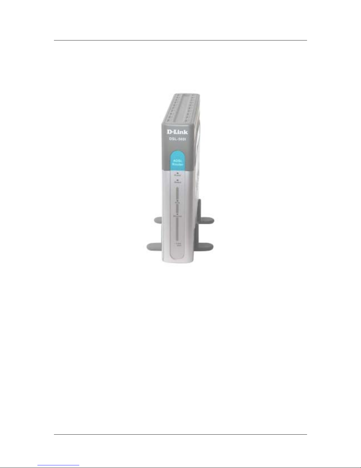
Front Panel
Place the Router in a location that allows a view of the LED indicators on the front panel.
3
Page 14
DSL-560I ADSL Router User’s Guide
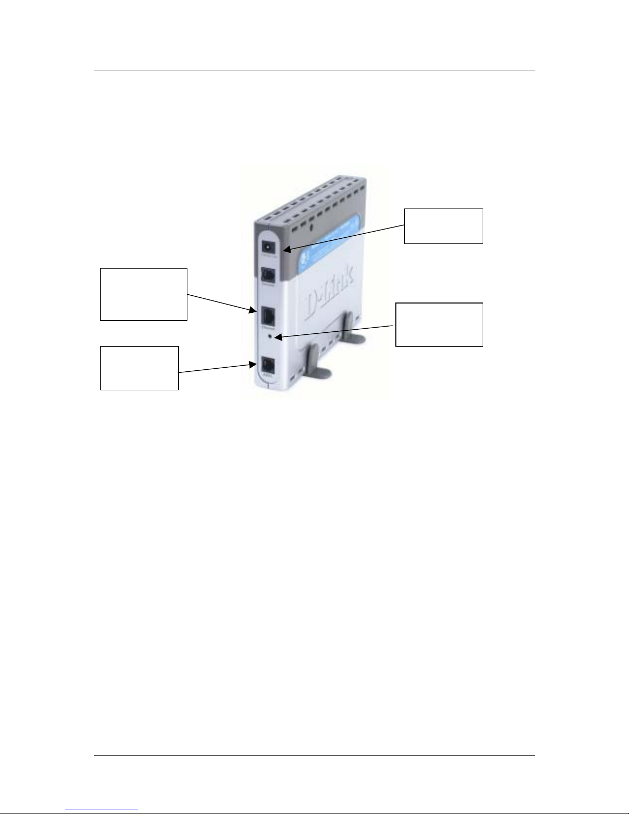
Rear Panel
All cable connections to the Router are made at the rear panel. The power switch and factory reset button is
located here as well.
Power Cord
connects here.
Ethernet port,
connect
thernet cable E
here
The factory rese
t
b
utton is locate
d
here.
ADSL port,
connect ADSL
cable here
4
Page 15
DSL-560I ADSL Router User’s Guide
LED Indicators
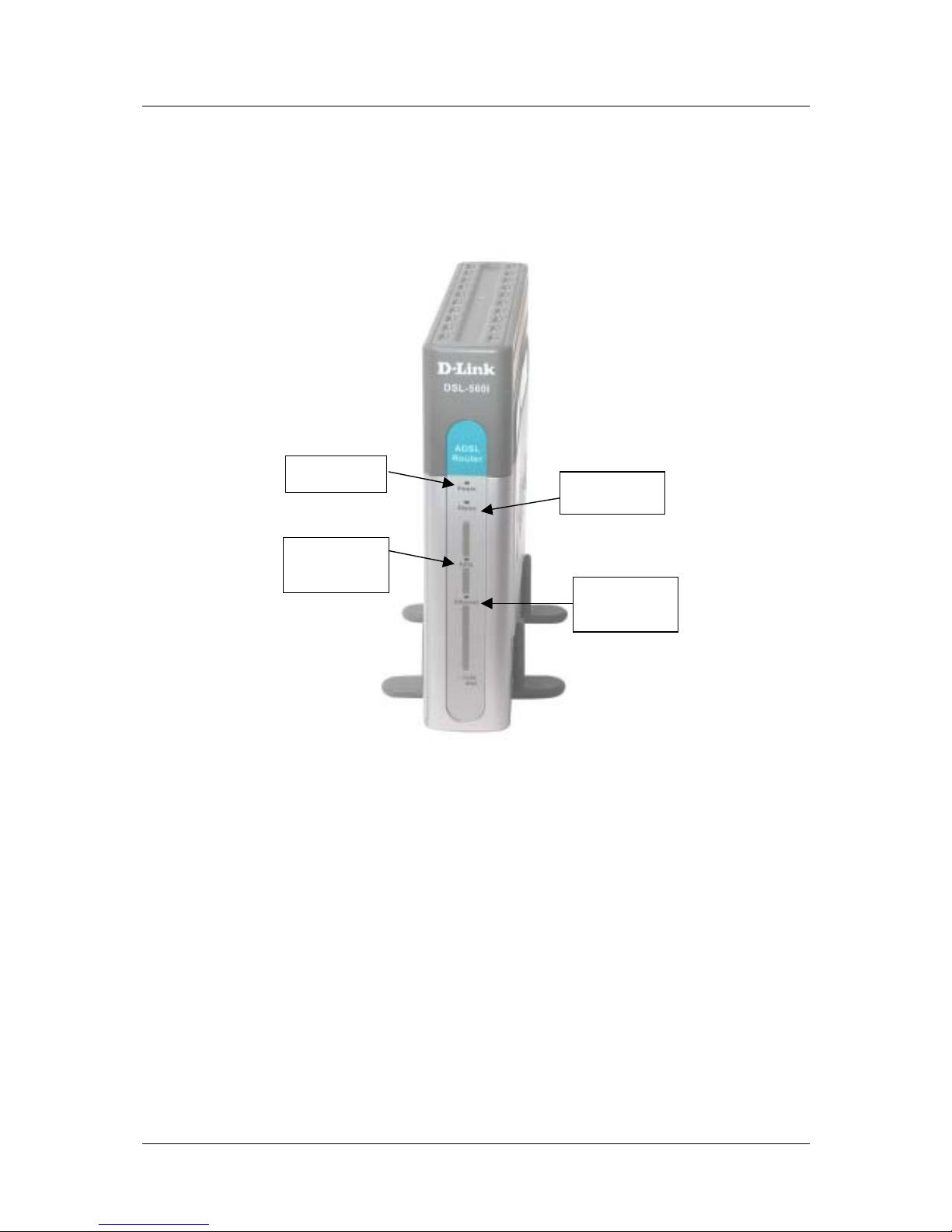
Power
Status
Ethernet
Link/Activity
ADSL
Link/Activity
The LED Indicators read as follows:
Power Steady green light indicates the unit is powered on.
Status Blinking light indicates a normal state. Off or steady On means the device is malfunction.
ADSL: Link Steady green light indicates a valid ADSL connection. This will light after the ADSL
negotiation process has been settled.
ADSL: Act Blinking green light indicates an active WAN session.
5
Page 16

DSL-560I ADSL Router User’s Guide
Ethernet: Link Steady green light indicates a valid Ethernet connection.
Ethernet: Act Blinking green indicates an active Ethernet session.
6
Page 17
DSL-560I ADSL Router User’s Guide
Hardware Installation
In this chapter you will learn about the various connections you will need to make in order to use the Router.
When selecting the location for the Router, make sure to allow room to access the connections on the rear panel.
You will want to place the Router so that you will be able to see the LED indicators on the front panel. Allow
some space above the Router for ventilation to avoid problems with overheating.
It may be convenient for you by placing the Router near the PC which you intend to use for initial Router
configuration.
Connect ADSL Line
Use the standard phone cable that comes with the Router to connect it to your telephone outlet. Simply plug one
end of the cable into the Router’s ADSL port (RJ-11 receptacle) on its rear panel, and insert the other end into
the wall jack. The ADSL connection is the WAN interface. It links the Router to the network serv ice provider’s
backbone infrastructure. This is the Router’s access point to the Internet.
The Router must undergo a negotiation process to establish the terms of the ADSL connection. During this
negotiation the ADSL Link/Activity LED will flash in a steady interval, after the line is established which it will
become steadily On. When the ADSL line traffic starts, it will then begin flashing according to the traffic
activities. If the ADSL line is disconnected, the whole ADSL negotiation process will repeat itself again.
Compuer to Router Connection
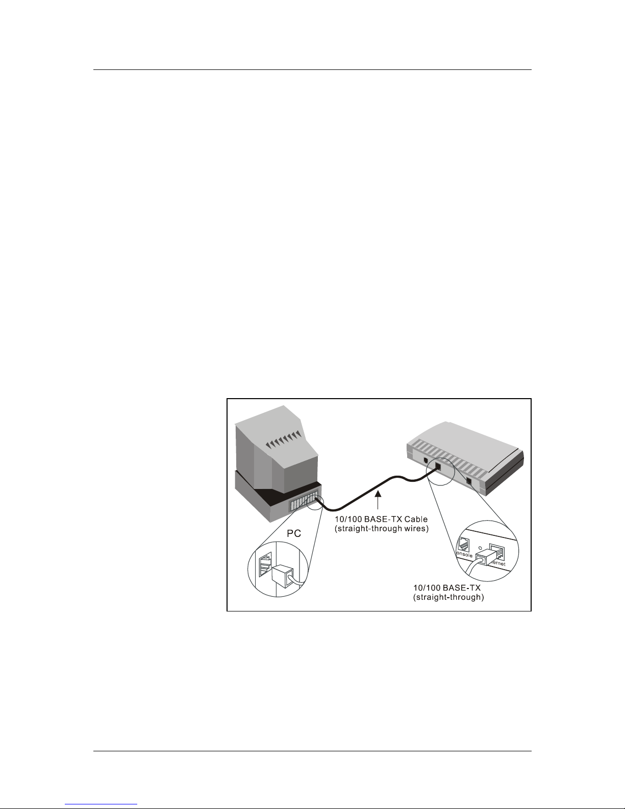
You can connect the Router
directly to a 10/100BASETX Ethernet adapter card
(NIC) installed on a PC
using the Ethernet cable
provided as shown in this
diagram.
7
Page 18
DSL-560I ADSL Router User’s Guide
Connect Ethernet LAN to Router
The Router may be connected to any 10/100BASE-TX Ethernet LAN. Any connection to an Ethernet
concentrating device such as a switch or hub can operate at a speed of 10/100 Mbps. When connecting the
Router to any Ethernet device that is capable of operating at speeds higher than 10Mbps, be sure that the
Ethernet device has auto-negotiation (NWay) enabled for the connecting port.
Use standard CAT-5 cable with RJ-45 connectors. The RJ-45 port on the Router is a crossed port (MDI-X).
Follow standard Ethernet guidelines when deciding what type of cable to use to make this connection. When
connecting the Router directly to a PC or server use a normal straight-throug h cable. You should use a crossed
cable when connecting the Router to a normal (MDI-X) port on a switch or hub. Use a normal straight-through
cable when connecting it to an uplink (MDI-II) port on a hub or switch. The Ethernet Link LED indicator will
indicate a valid connection.
The rules governing Ethernet cable lengths apply to the LAN to Router connection. Be sure that the cable
connecting the LAN to the Router does not exceed 100 meters.
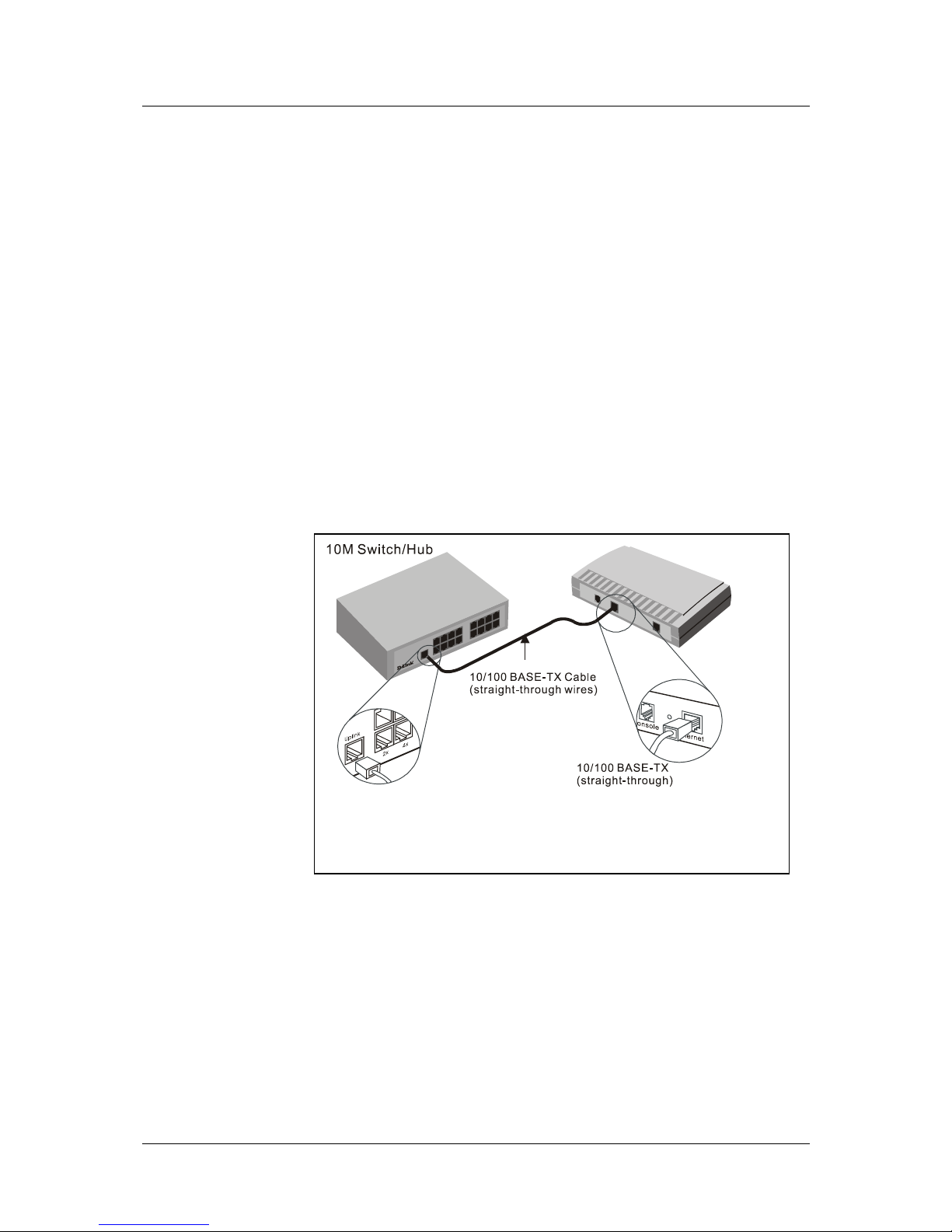
Hub or Switch to Router Connection
Connect the Router to an uplink port (MDI-II) on an Ethernet hub or switch with a straight-through CAT-5
networking twisted pair cable as shown in the diagram below:
If you wish to reserve
the uplink port on the
switch or hub for
another device, connect
to any on the other MDIX ports (1x, 2x, etc.)
with a crossed cable.
8
Page 19

DSL-560I ADSL Router User’s Guide
Power On Router
To power on the device:
1. Insert the AC Power Adapter cord into the power receptacle located on the Router’s back panel, and plug
the adapter into a nearby power source.
2. You should see the Power LED indicator light up and remain lit.
9
Page 20

DSL-560I ADSL Router User’s Guide
4
Configuring the Router for the First Time
The first time you setup the Router, it is recommended that you configure the Rou ter’s WAN connection by
using a single stand-alone computer that only connects to the Router’s Ethernet port. Once the WAN port is
properly setup and its connection is fully functional, you may continue making changes to its other
configurations including the IP settings and/or its DHCP server options. This chapter will focus on how to
properly setup your Router’s WAN connection. The following chapter describes the various menus used to
configure and monitor the Router including how to change IP settings and DHCP server options.
WAN Configuration Summary
1. Connect to the Router To configure the Router’s WAN connection, it is necessary to communicate
with the Router through its management interface, which is HTML-based, and it can be accessed using
a web browser. To access the management software, your computer must be able to “see” the Router.
Your computer can see the Router if it is in the same “neighborhood” or subnet as the Router’s. This is
accomplished by making sure that your computer has the correct IP settings which place it in the same
subnet as the Router’s. The easiest way to make sure your computer has the correct IP settings is to
enable your PC’s DHCP client option, and to automatically get the assigned IP addresses from the
default Router’s DHCP server operation. The next section describes how to change the IP configuration
for a computer running a Windows OS to be a DHCP client.
2. Configure the WAN Connection Once you have successfully logged-in the Router’s Web
configuration menu, you can proceed to change the settings for the ADSL connection and the Service
Provider’s signing-on process. There are different methods used to establish the connection to the
service provider’s network and ultimately to the Internet. You should know what Encapsulation and
connection type you are required to use for your ADSL service. It is also possible that you must change
the PVC settings used for the ADSL connection. Your service provider should provide all the
information you need to configure the WAN connection.
Configuring IP Settings on Your Computer
In order to configure your system to receive IP addresses from the Router, it must first have the TCP/IP protocol
installed. If you have an Ethernet port on your computer, it probably already has TCP/IP protocol installed. If
you are using Windows XP, the TCP/IP is enabled by default for the standard installations. Below is an
illustrated example of how to configure a Windows XP system to automatically ob tain the IP addresses fro m the
Router. Following this example is a step-by-step description of the procedures used with other Windows
operating systems. No matter what OS you have loaded on the PC, you will need to check first to see if its
TCP/IP protocol has been installed. If the TCP/IP protocol is not installed, you will need to go through the PC’s
network protocol installation process (provided in the later session) to properly install the TCP/IP protocol. Once
the protocol has been installed you can configure the PC to receive IP addresses from the Router.
10
Page 21
DSL-560I ADSL Router User’s Guide
Configure Windows XP for DHCP
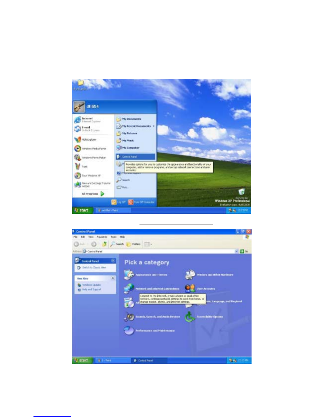
Use the following steps to configure a computer running Windows XP to be a DHCP client.
1. From the Start menu on your desktop, go to click on Control Panel.
2. In the Control Panel folder, click on Network and Internet Connections
.
11
Page 22
DSL-560I ADSL Router User’s Guide
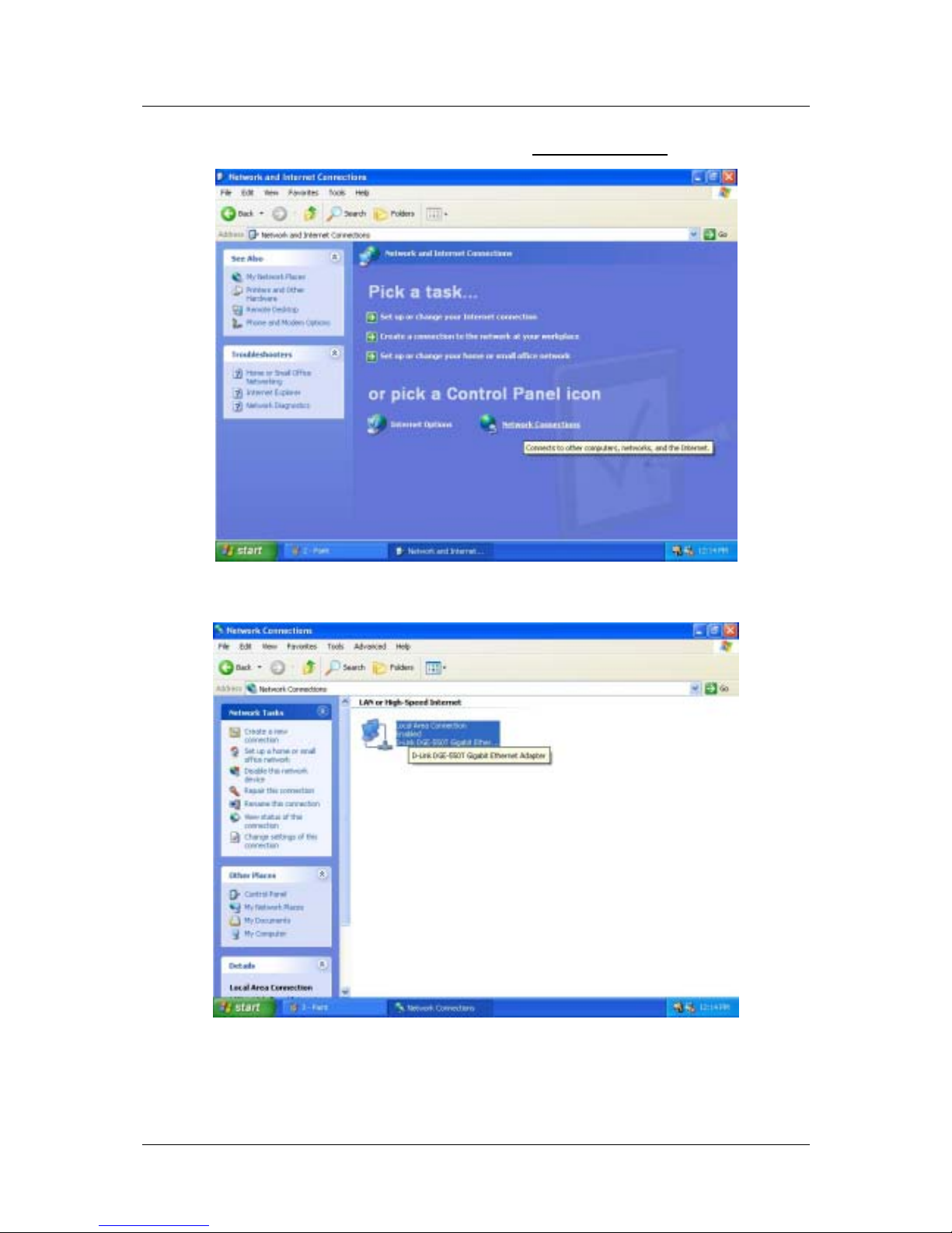
3. In the Network and Internet Connections folder, click on Network Connections
.
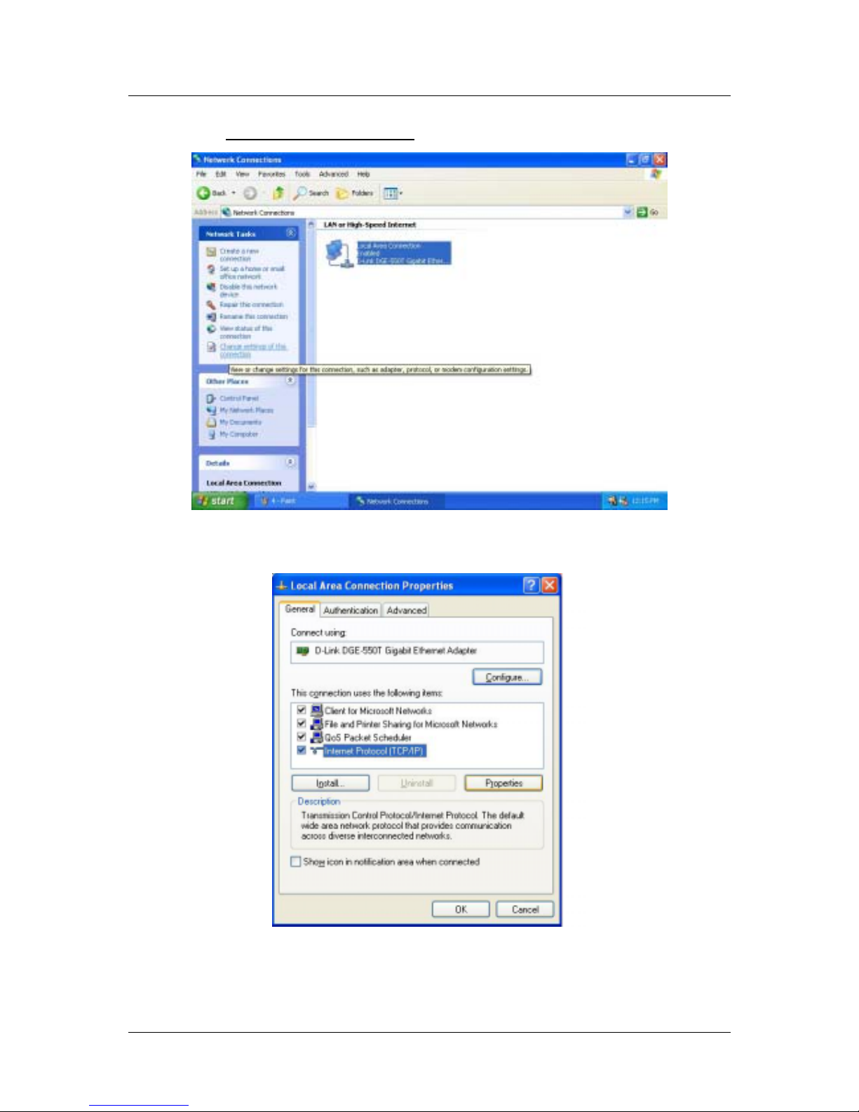
4. In the Network Connections folder, highlight the Local Area Connection icon by clicking on it once.
A new option is revealed under Network Tabs in the left side panel.
12
Page 23
DSL-560I ADSL Router User’s Guide
5. Click on Change settings of the connection
under Network Tabs.
6. In the General Tab of the Local Area Connection Properties menu, highlight Internet Protocol
(TCP/IP) under “This connection uses the following items:” by clicking on it once. Click on the
Properties button.
13
Page 24
DSL-560I ADSL Router User’s Guide
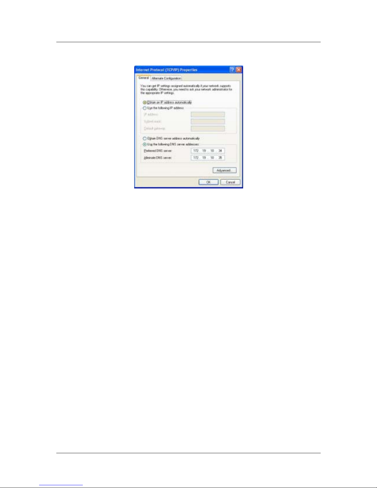
7. Select “Obtain an IP address automatically” by clicking once in the circle. Click the OK button.
Your computer is now ready to obtain its IP addresses from the Router’s DHCP server.
Windows 2000
First, check for the IP protocol and, if necessary, install it:
1. In the Windows task bar, click the Start button, point to Settings, and then click Control Panel.
2. Double-click the Network and Dial-up Connections icon.
3. In the Network and Dial-up Connections window, right-click the Local Area Connection icon, and then
select Properties.
4. The Local Area Connection Properties dialog box displays with a list of currently installed network
components. If the list includes Internet Protocol (TCP/IP), then the protocol has already been enabled,
skip ahead to Configure Windows 2000 for DHCP.
5. If Internet Protocol (TCP/IP) does not display as an installed component, click Install.
6. In the Select Network Component Type dialog box, select Protocol, and then click Add.
7. Select Internet Protocol (TCP/IP) in the Network Protocols list, and then click OK.
8. You may be prompted to install files from your Windows 2000 installation CD or other media. Follow the
instructions to install the files.
9. If prompted, click OK to restart your computer with the new settings.
Configure Windows 2000 for DHCP
1. In the Control Panel, double-click the Network and Dial-up Connections icon.
2. In Network and Dial-up Connectio ns window, right-click the Local Area Connection icon, and then
select Properties.
3. In the Local Area Connection Properties dialog box, select Internet Protocol (TCP/IP), and then click
Properties.
4. In the Internet Protocol (TCP/IP) Properties dialog box, click the button labeled Obtain an IP address
automatically.
5. Double-click OK to confirm and save your changes, and then close the Control Panel.
Your computer is now ready to obtain its IP addresses from the Router’s DHCP server.
14
Page 25

DSL-560I ADSL Router User’s Guide
Windows ME
First, check for the IP protocol and, if necessary, install it:
1. In the Windows task bar, click the Start button, point to Settings, and then click Control Panel.
2. Double-click the Network and Dial-up Connections icon.
3. In the Network and Dial-up Connections window, right-click the Network icon, and then select
Properties.
4. The Network Properties dialog box displays with a list of currently installed network components. If the
list includes Internet Protocol (TCP/IP), then the protocol has already been enabled. Skip ahead to
Configure Windows ME for DHCP.
5. If Internet Protocol (TCP/IP) does not display as an installed component, click Add.
6. In the Select Network Component Type dialog box, select Protocol, and then click Add.
7. Select Microsoft in the Manufacturers box.
8. Select Internet Protocol (TCP/IP) in the Network Protocols list, and then click OK.
9. You may be prompted to install files from your Windows Me installation CD or other media. Follow
the instructions to install the files.
10. If prompted, click OK to restart your computer with the new settings.
Configure Windows ME for DHCP
1. In the Control Panel, double-click the Network and Dial-up Connections icon.
2. In Network and Dial-up Connections window, right-click the Network icon, and then select Properties.
3. In the Network Properties dialog box, select TCP/IP, and then click Properties.
4. In the TCP/IP Settings dialog box, click the Obtain and IP address automatically option.
5. Double-click OK twice to confirm and save your changes, and then close the Control Panel.
Your computer is now ready to obtain its IP addresses from the Router’s DHCP server.
Windows 95, 98
First, check for the IP protocol and, if necessary, install it:
1. In the Windows task bar, click the Start button, point to Settings, and then click Control Panel.
Double-click the Network icon.
2. The Network dialog box displays with a list of currently installed network components. If the list
includes TCP/IP, and then the protocol has already been enabled, skip to Configure IP Information
Windows 95, 98.
3. If TCP/IP does not display as an installed component, click Add. The Select Network Component Type
dialog box displays.
4. Select Protocol, and then click Add. The Select Network Protocol dialog box dis pl ay s .
5. Click on Microsoft in the Manufacturers list box, and then click TCP/IP in the Network Protocols list
box.
6. Click OK to return to the Network dialog box, and then click OK again. You may be prompted to
install files from your Windows 95/98 installation CD. Follow the instructions to install the files.
7. Click OK to restart the PC and complete the TCP/IP installation.
15
Page 26

DSL-560I ADSL Router User’s Guide
Configure Windows 95, 98 for DHCP
1. Open the Control Panel window, and then click the Network icon.
2. Select the network component labeled TCP/IP, and then click Properties.
3. If you have multiple TCP/IP listings, select the listing associated with your network card or adapter.
4. In the TCP/IP Properties dialog box, click the IP Address tab.
5. Click the Obtain an IP address automatically option.
6. Double-click OK to confirm and save your changes. You will be prompted to restart Windows.
7. Click Yes.
When the PC is restarted, your computer is ready to obtain its IP addresses from the Router’s DHCP server.
Windows NT 4.0 workstations:
First, check for the IP protocol and, if necessary, install it:
1. In the Windows NT task bar, click the Start button, point to Settings, and then click Control Panel.
2. In the Control Panel window, double click the Network icon.
3. In the Network dialog box, click the Protocols tab.
4. The Protocols tab displays a list of currently installed network protocols. If the list includes TCP/IP,
then the protocol has already been enabled. Skip to “Configure IP Information”
5. If TCP/IP does not display as an installed component, click Add.
6. In the Select Network Protocol dialog box, select TCP/IP, and then click OK. You may be prompted to
install files from your Windows NT installation CD or other media. Follow the instructions to install the
files.
7. After all files are installed, a window displays to inform you that a TCP/IP service called DHCP can be
set up to dynamically assign IP information.
8. Click Yes to continue, and then click OK if prompted to restart your computer.
Configure Windows NT 4.0 for DHCP
1. Open the Control Panel window, and then double-click the Network icon.
2. In the Network dialog box, click the Protocols tab.
3. In the Protocols tab, select TCP/IP, and then click Properties.
4. In the Microsoft TCP/IP Properties dialog box, click the Obtain an IP address automatically option.
5. Click OK twice to confirm and save your changes, and then close the Control Panel.
16
Page 27
DSL-560I ADSL Router User’s Guide
Access the Configuration Manager
Now that your computer’s IP settings allow it to communicate with the Router, you can access the configuration
software.
Note: Be sure that the web browser on your computer is not configured to use a proxy
server in the Internet settings. In Windows Internet Explorer, you can check if a proxy
server is enabled using the following procedure:
1. In Windows, click on the START button, go to Settings and choose Control Panel.
2. In the Control Panel window, double-click on the Internet Options icon.
3. Click the Connections tab and click on the LAN Settings button.
4. Verify that the “Use proxy server” option is NOT checked. If it is checked, click in the
checked box to deselect the option and click OK.
Alternatively you can access this Internet Options menu using the Tools pull down menu
in Internet Explorer.
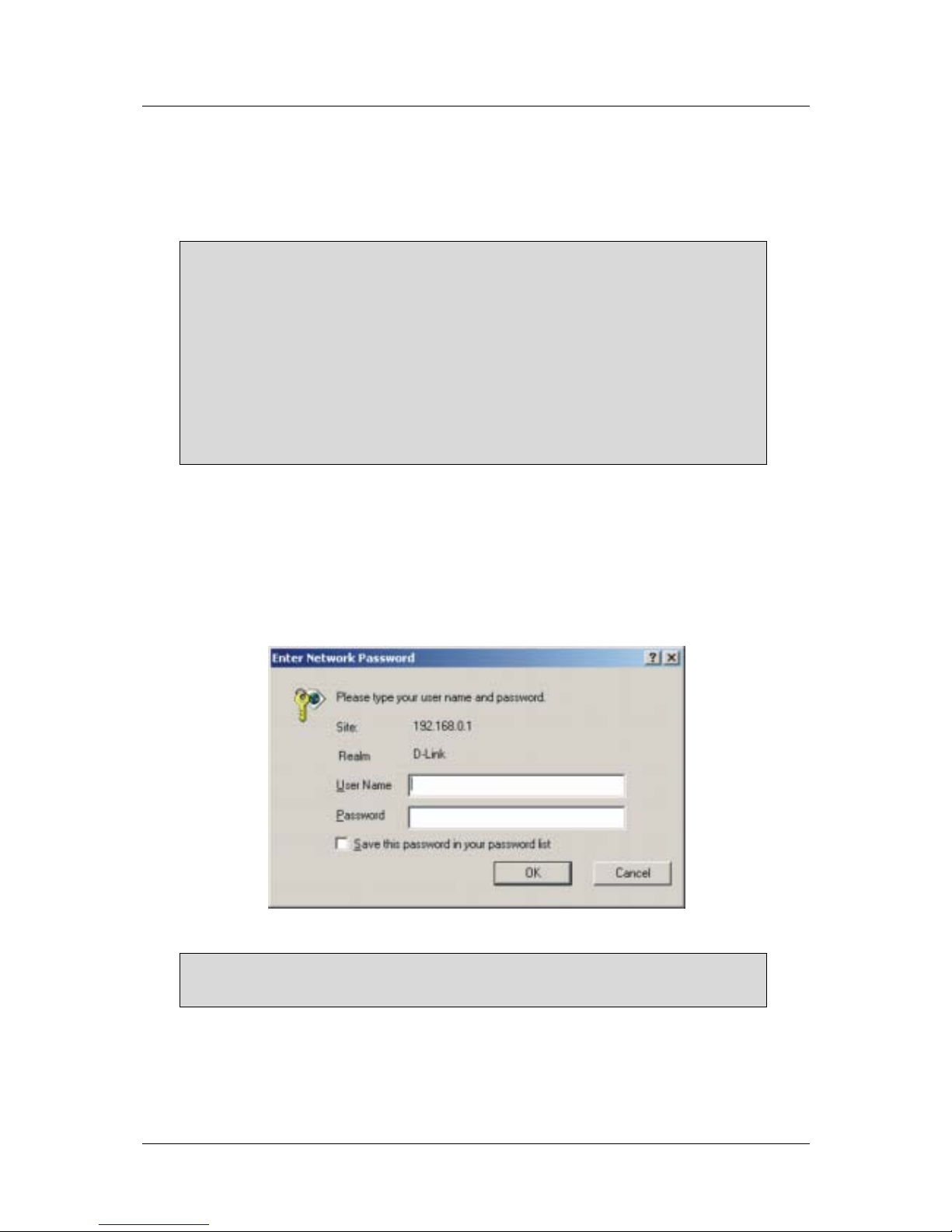
To use the web-based management software, launch a suitable web browser and direct it to the IP address of the
Router. Type in http:// followed by the default IP address, 192.168.0.1 in the address bar of the browser. The
URL in the address bar should read: http://192.168.0.1.
A new window will appear and you will be prompted for a user name and password to access the web-based
manager. Use the default user name admin and password admin for first time set up. You should change the
web-based manager access user name and password once you have verified that a connection can be established.
The user name and password allows any PC within the same subnet as the Router to access the web-based
manger.
Figure 4 - 1. Login to Router
Note: Do not confuse the user name and password used to access the web-based
manager with the ADSL account user name and password needed for PPP connections
to access the service provider’s network.
Configure the Router
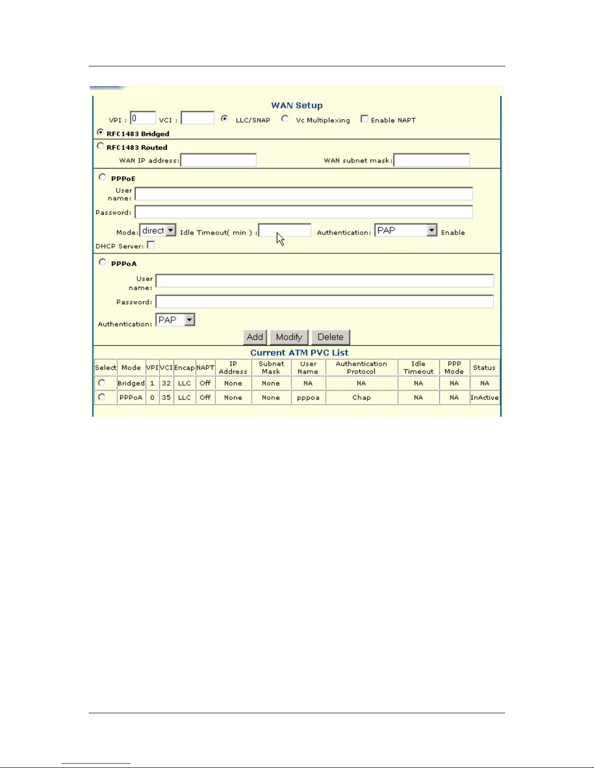
The WAN Setup page displays the menu you need to configure the Router so it can connect to the Internet. The
WAN Setup menu is used to configure the Router’s WAN connection and also used to add other virtual
connections (PVCs). The remainder of this chapter describes how to establish this WAN connection.
17
Page 28
DSL-560I ADSL Router User’s Guide
Figure 4 - 1. Configuring the WAN Connection (First Time Setup)
When the Router is used to provide Internet access it actually must first access your service provider’s network,
that is, it must communicate with computers and other routers owned by your service provider. These computers
and routers then provide access to the Internet. The Router must be configured to communicate with the systems
that give it access to the larger network. There are different methods or protocols used to make this
communication possible, and both ends of the communication must agree on what method to use and how to set
up the connection. This is what you will configure the Router to do, to agree with the service provider’s
equipment and negotiate the terms of the connection using a language or protocol that both sides understand.
Sometimes it is also necessary to configure settings that control the actual ADSL connection. The ADSL
connection is what actually carries the data from one point to the other. So in addition to telling the Router what
method it must use, you may also be asked to change the PVC (Permanent Virtual Channel) settings. These
settings are defined by two numbers, the VPI (Virtual Path Indicator) and the VCI (Virtual Channel Indicator).
All the information you need to make the changes needed for a functioning WAN connection should have been
provided to you by your ISP or network service provider.
To configure the WAN connection, open the WAN Setup menu and perform the steps listed below. Some of the
settings do not need to be changed when you first set up the device but can be changed later if you choose.
1 Do not change the VPI or VCI values unless you are required to do so. If these settings are incorrect, the
ADSL connection will not function. Many users will be able to use the default settings. If you are told to
change these, type in the values given to you by your service provider.
18
Page 29

DSL-560I ADSL Router User’s Guide
2 Select the Encapsulation method used for your connection. The options available are RFC1483Bridged,
RFC1483Routed, PPPoE, and PPPoA. The default Encapsulation is RFC1483 Bridged.
3 The remaining settings that must be configured are different for the different Encapsulations.
3.1 If you have selected a PPPoE or PPPoA Encapsulation you must supply a User Name and Password
used to verify the identity of your account. Type in the User Name and Password used for your PPP
connection. Also select the Authentication method used, pap or chap, choose Enabled for Connect On
Demand and leave the Idle Time setting at 0.
3.2 If you have selected a Bridge Encapsulation, there is no more change needed to establish the WAN
connection for the Router. However, you will probably have to install some sor t of connection software
on your computer. Go to step 6 and finalize the Router configuration, then install any additional
software. Follow the instructions given to you by your ISP or network service provider.
4 Click the Add button when you have entered all the information. The web browser will briefly go blank.
After a few seconds the PVC profile listed in the Current ATM PVC List at the bottom of the web page will
show the changes that you have just configured.
19
Page 30

DSL-560I ADSL Router User’s Guide
5
Web-based Management
The DSL-560I offers a web-based (HTML) graphical user interface allowing users to manage the Router from
anywhere on the LAN using a standard browser. A web browser is used to communicate directly with the Router
and make changes to the configuration or monitor status.
Accessing the Web Manager
In order to use the web-based management software it will be necessary to use a computer that occupies the
same subnet as the Router. The simplest way to do this for many users will be to use DHCP server that is
enabled by default on the Router. Chapter 4 provides instructions on how to configure a system running
Windows operating systems to be DHCP client. You may also specify IP settings for your computer. The Router
has a default IP address of 192.168.0.1 and a subnet mask of 255.255.255.0. Once you have accessed the
configuration software you can configure the Router’s IP settings and DHCP server configuration to suit your
preferences.
To use the web-based management software run the browser you have installed on your computer and direct it to
the Router’s HTML interface using its LAN IP address. If this is the first time you are accessing the web-based
manager you must type its default IP address, 192.168.0.1 in the address bar of the browser. The URL in the
address bar should read: http://192.168.0.1. If you change the IP address you will use the new IP address to
access the web-based manager.
In the page that opens, click on the Login to web-based management module button.
A new window will appear and you will be prompted for a user name and password. Use default user name
admin and password admin for first time set up.
Note: Be sure that the web browser on your computer is not configured to use a proxy
server in the Internet settings. In Windows Internet Explorer, you can check if a proxy
server is enabled using the following procedure:
1. In Windows, click on the START button, go to Settings and choose Control Panel.
2. In the Control Panel window, double-click on the Internet Options icon.
3. Click the Connections tab and click on the LAN Settings button.
4. Verify that the “Use proxy server” option is NOT checked. If it is checked, click in the
checked box to deselect the option and click OK.
Alternatively you can access this same menu using the Tools pull down menu in
Internet Explorer.
If this is the first time you are accessing the configuration manager and you simply want
to establish a connection to the Internet, you may want to read the section titled
Configure the Router in the previous chapter.
20
Page 31
DSL-560I ADSL Router User’s Guide
Folders and Menus
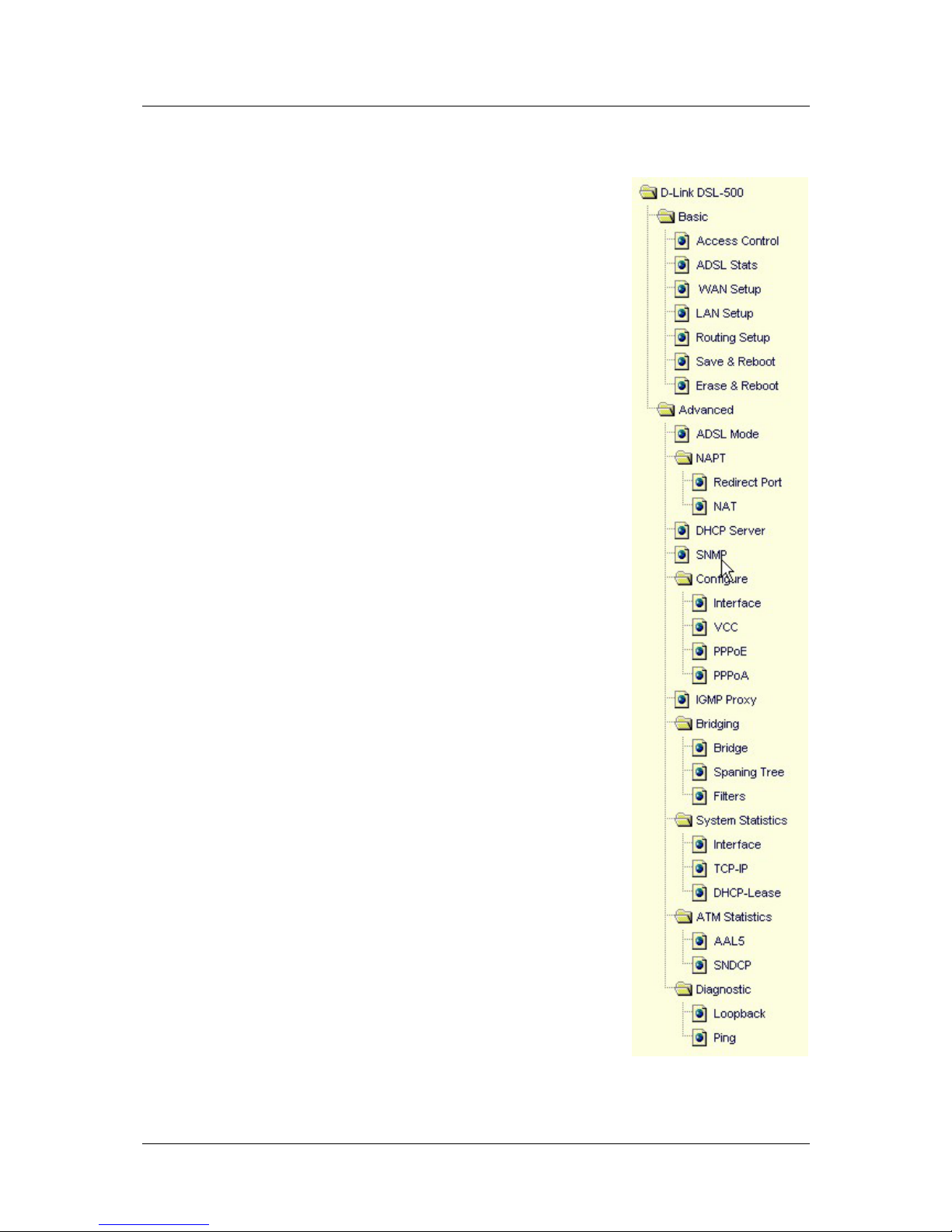
The web manager interface (GUI) displays two fields that can be scrolled with
your mouse to view areas of the field that may be hidden from view. The field
located on the left side of the GUI contains two folders that can be opened with
a double left click of the mouse. Open the Basic and Advanced folders and you
will see that they each contain a number of labeled buttons. You can click the
button or the hyperlinked title of these buttons to view the menu associated with
it. These are the menus you will use to configure, manage and monitor the
Router.
Basic
The information contained in the Basic folder are
• Access Control
• ADSL Stats
• WAN Setup
• LAN Setup
• Routing Setup
• Save & Reboot
• Erase & Reboot
Router Configuration
All the settings that define Router operations on both the LAN and WAN can be
configured with the menus located in the Basic folder. These menus are
described in the first part of this chapter presented in the same order that they
appear in your browser.
The Advanced folder contains menus useful for system upkeep and analysis.
These menus are described later in this chapter.
21
Page 32
DSL-560I ADSL Router User’s Guide
Configuring the WAN Connection
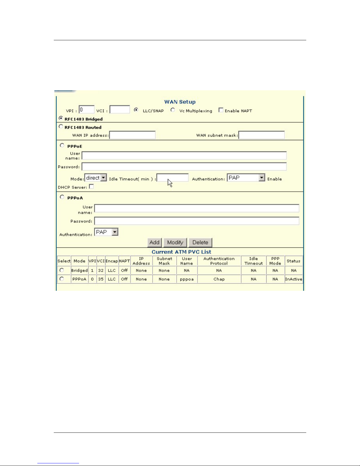
Use the WAN Setup menu to configure the WAN interface for PVC settings and other settings used to configure
the ADSL connection and the connection to the service provider’s network. Use this menu to add, change or
delete PVC connection profiles if you have a multiple PVC account.
Figure 5 - 1. WAN Configuration
The Router may be configured to use common Encapsulation and connection methods commonly used for
ADSL service. The information that is needed for the different method varies according to connection type.
Therefore the menu will change to offer different settings depending on whether the connection is a PPP or
Bridged connection type.
To configure a single PVC profile, select the Encapsulation setting first. This may change the user configurable
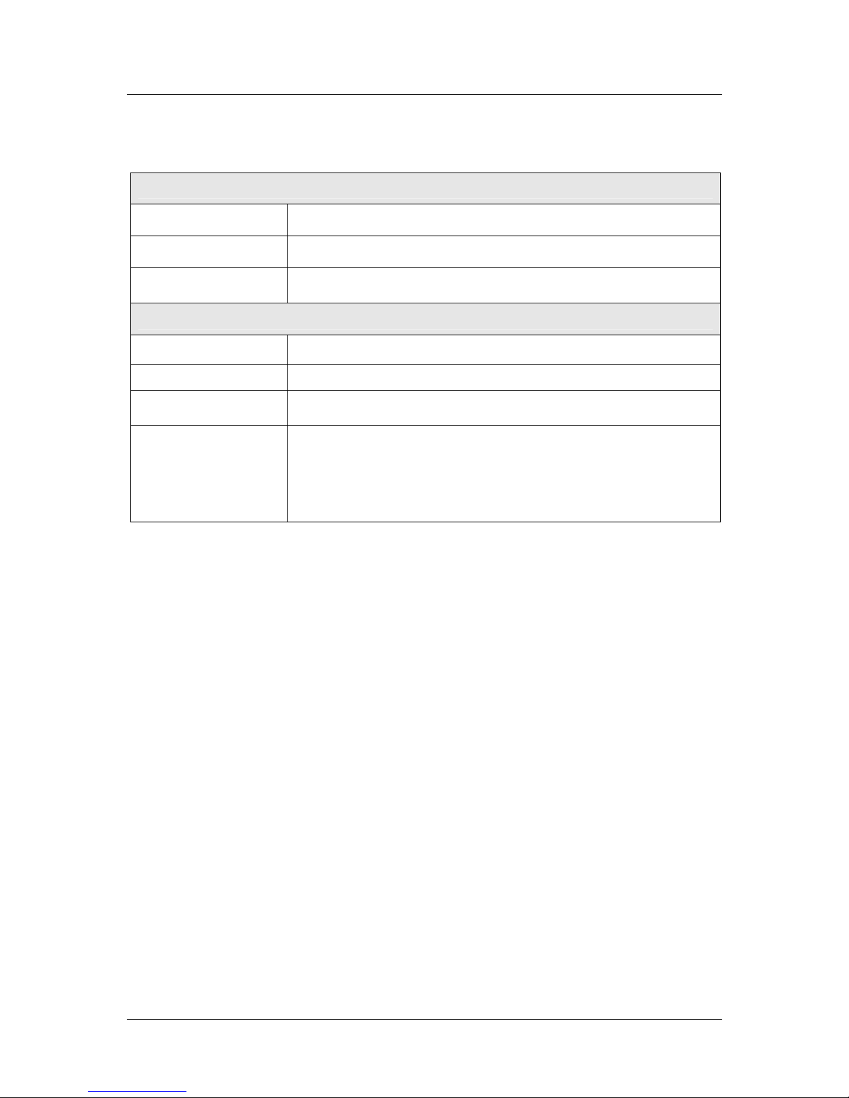
variables that are offered. The default Encapsulation used is RFC1483 Bridged. Table 5 - 1. WAN Connection
Configuration on the next page lists the configuration settings for the different Encapsulation types.
22
Page 33
DSL-560I ADSL Router User’s Guide
In the WAN Setup menu configure the WAN interface settings described in the table below.
All connections must configure:
VPI
Type in the new VPI setting (0-255)
VCI
Type in the new VCI setting (32-65535)
Encapsulation
From the drop-down menu select RFC1483 Bridged, RFC1483 Routed,
PPPoE, PPPoA. Default=RFC1483 Bridged.
PPP Connections must configure:
Login User Name
Used for authentication by your network service provider.
Login Password
Used for authentication by your network service provider
Authentication
Protocol used to confirm the identity of the subscriber. Choose chap
(default) or pap form the drop-down menu.
Idle Time
A value of 0 means that the PPP connection will remain connected. If
your network account is billed according to the amount of time the
Router is actually connected to the Internet, enter an appropriate Idle
Time value (in seconds). This will disconnect the Router after the WAN
connection has been idle for the amount of time specified. The default
value = 0.
Table 5 - 1. WAN Connection Configuration
Additional Virtual Connections (PVCs)
The Router can use up to eight simultaneous PVC connections. These additiona l connections occupy the same
bandwidth used for ADSL service. Additional PVC connections can be added to establish a pr iv ate connectio n to
remote offices or maintain a server accessible through the WAN port. Provision for additional PVC profiles must
be done through the telephone company or telecommunications services company. The remote user must have
suitable ADSL equipment for a successful connection.
Use the WAN Setup menu to add, delete or modify additional PVCs as described below.
23
Page 34
DSL-560I ADSL Router User’s Guide
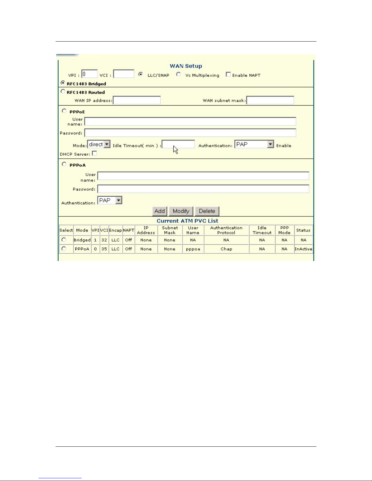
Figure 5 - 2. Multiple PVC Menu
In order to use additional PVCs, each profile must have a unique (to the Router) Item Name and a unique
VCI/VCI combination. You may use any available Encapsulation or connection type. Follow the instructions on
the next page to set up multiple PVCs.
To add a PVC:
1. Type in a new VPI and VCI value. This combination may not be used for another PVC profile on the
Router.
2. Select the Encapsulation method used for the new PVC.
3. For PPP connections (PPPoE or PPPoA), you must supply a new User Name and Password. You may
use the same user name/password combination for more than one PVC unless you are specifically told
not to do this by your service provider. It is recommended however that a different combination be used
whenever it is practical. Also for PPP connections, select the Authentication and Idle Time settings
(see Table 5 - 1. WAN Connection Configuration).
4. Click the Add bu tton wh en you ha ve en tered all the information. The web browser will briefly go blank.
After a few seconds the new PVC profile appears listed in the Current ATM PVC List at the bottom of
the web page.
.
To modify an existing PVC:
1. Select the PVC profile you want to change by clicking on the item in the Current ATM PVC List.
2. Change the settings as desired making sure not to duplicate a VPI/VCI setting.
24
Page 35

DSL-560I ADSL Router User’s Guide
3. Click the Modify button. The modified PVC profile will appear with the new settings in the Current
ATM PVC List menu.
To delete an exiting PVC:
1. Select the PVC profile you want to delete by selecting the item in the Current ATM PVC List.
2. Click the Delete button. The PVC profile will disapp ear from the Cu rrent ATM PVC List at the bottom
of the page.
25
Page 36
DSL-560I ADSL Router User’s Guide
Configuring LAN IP Settings
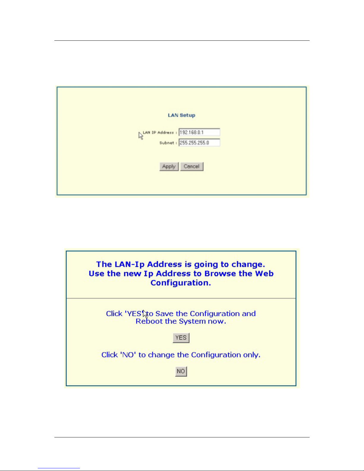
Use the LAN Setup menu to change the Router’s Ethernet LAN IP address.
Figure 5 - 3. Ethernet IP Address Menu
The Ethernet IP Address displays the current LAN IP settings of the Router. To change the IP address, type in
the new LAN IP Address in the space provided and type in a Su bnet Mask. Click on the Apply button.
You will be prompted again to restart the device. Restart now or continue to make changes and save the changes
later.
Figure 5 – 4.
26
Page 37
DSL-560I ADSL Router User’s Guide
Access Control
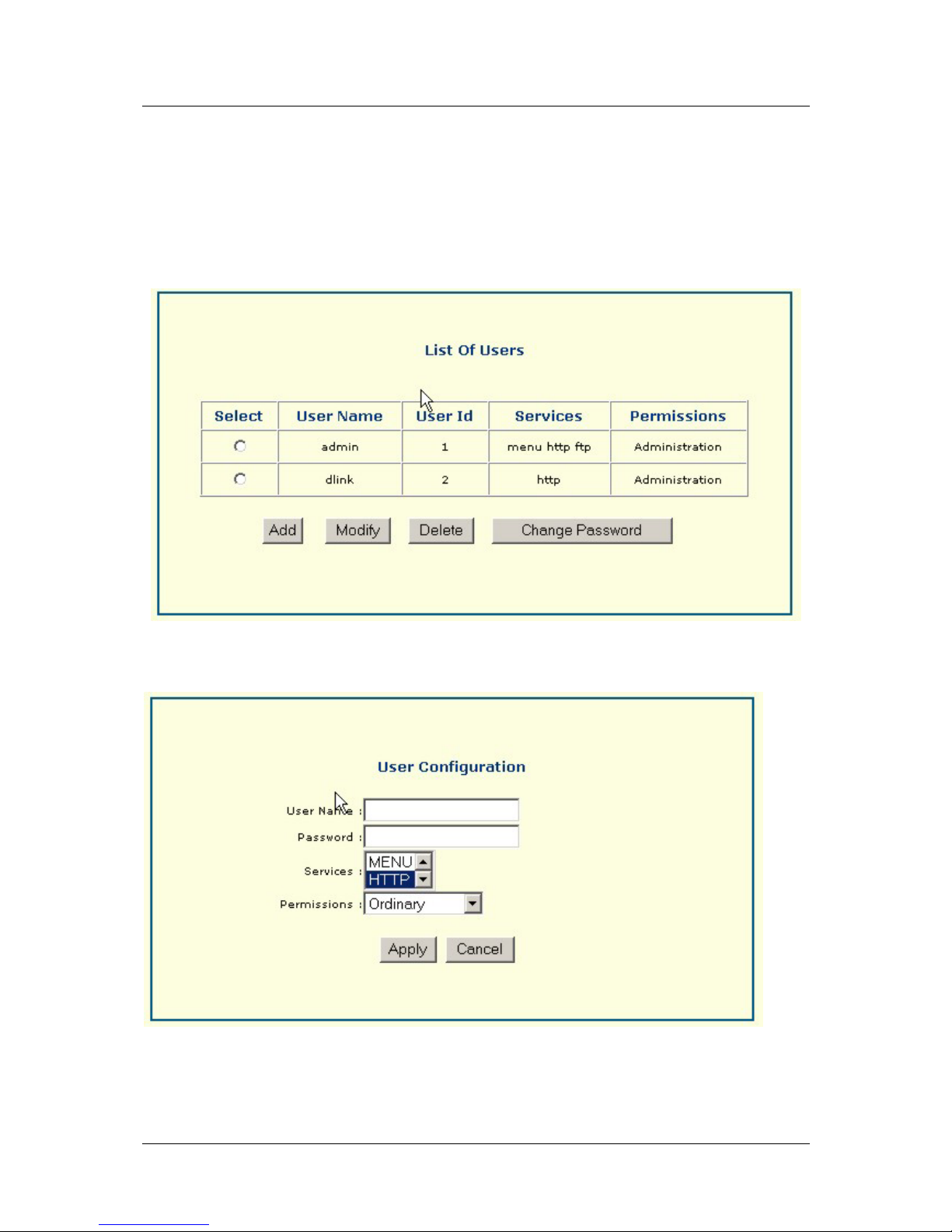
This menu allows you to change the user configuration (user name, password, and other options) to access the
web manager. You may add, modify, and delete new user profiles. You may also just change the password on
an existing user profile.
The following screen will appear when you click Add. Enter a User Name and Password. Select Menu or
HTTP under Services and enter Permissions. Then click Apply to create user profile. It will then appear under
List of Users.
The following screen will appear when you click Modify. Enter User Name, Authorization Old, Authorization,
and Permission settings. Then click Apply to put modifications into effect.
27
Page 38
DSL-560I ADSL Router User’s Guide
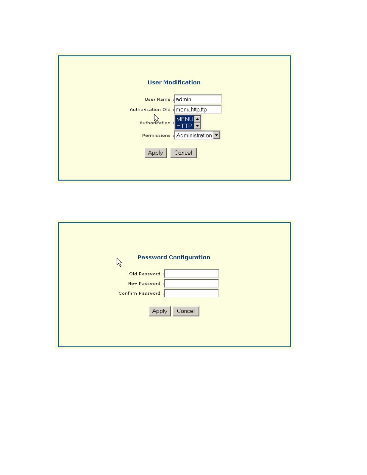
To change the password on a user profile that already exists click on Password to bring up the menu below.
Enter the Old Password, New Password, and Confirm Password settings to change password of existing user
profile.
28
Page 39
DSL-560I ADSL Router User’s Guide
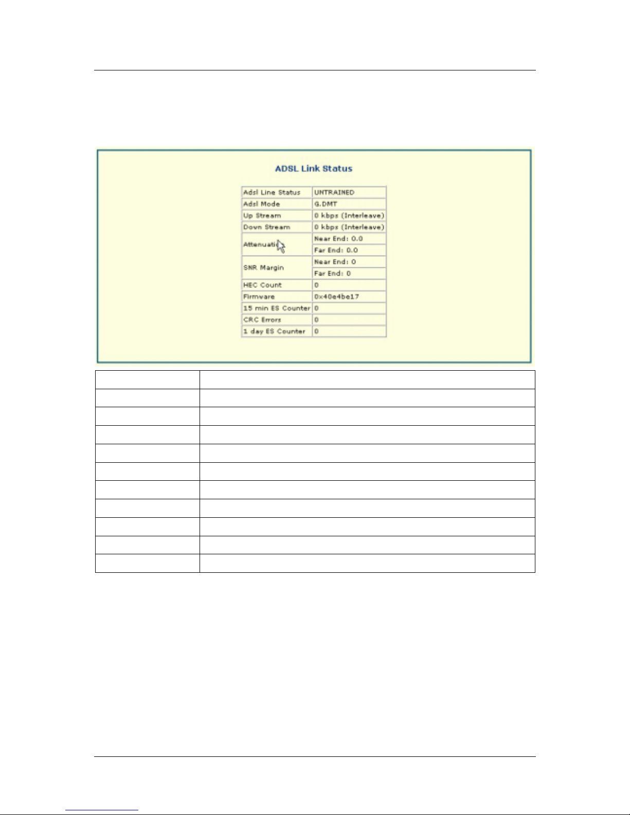
ADSL Link Status
This is a read-only menu item. The following table explains the information given in the ADSL Link Status
menu.
Adsl Line Status
Tells whether the line is trained or untrained.
Adsl Mode
Modulation technique used for ADSL connection, G.DMT or G.lite
Up Stream
Rate of data transmission upstream (kbps)
Down Stream
Rate of data transmission downstream (kbps)
Attenuation
Downstream/Upstream attenuation of signal in dB (Near end and Far end)
SNR Margin
Downstream/Upstream Signal-to-Noise Ratio in dB (Near end and Far end)
HEC Count
Header Error Check count
Firmware
Firmware version
15 min ES Counter
CRC Errors
Cyclic Redundancy Control errors
1 day ES Counter
29
Page 40
DSL-560I ADSL Router User’s Guide
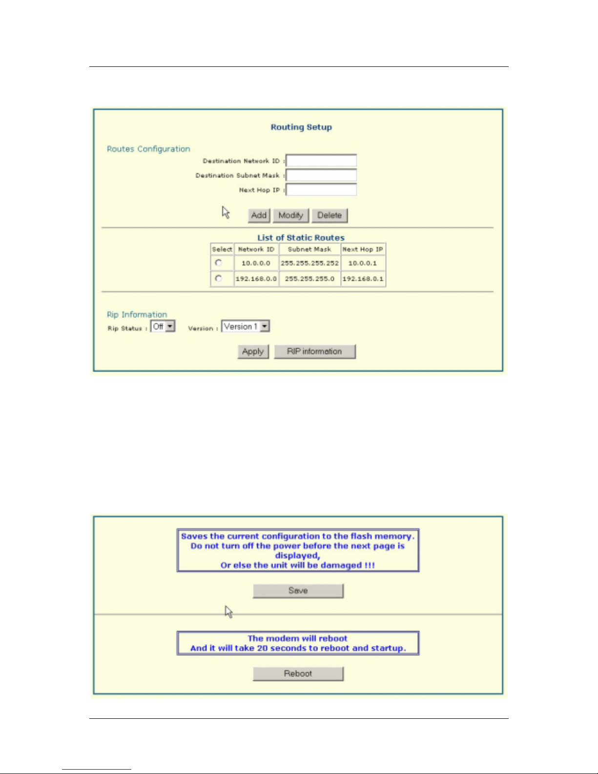
Routing Setup
Use Static Routing to specify a route used for data traffic within your Ethernet LAN or to route data on the WAN.
This is used to specify that all packets destined for a particular network or subnet use a predetermined gateway.
The List of Static Routes table tells you how many routes are currently configured and the Ne twork ID, Subnet
Mask, and Next Hop IP of each route. The Rip Information option lets you select Rip Status (Off or On) and
Version information.
Save and Reboot
Gives you to the option to save the current configuration or reboot the Router.
30
Page 41
DSL-560I ADSL Router User’s Guide
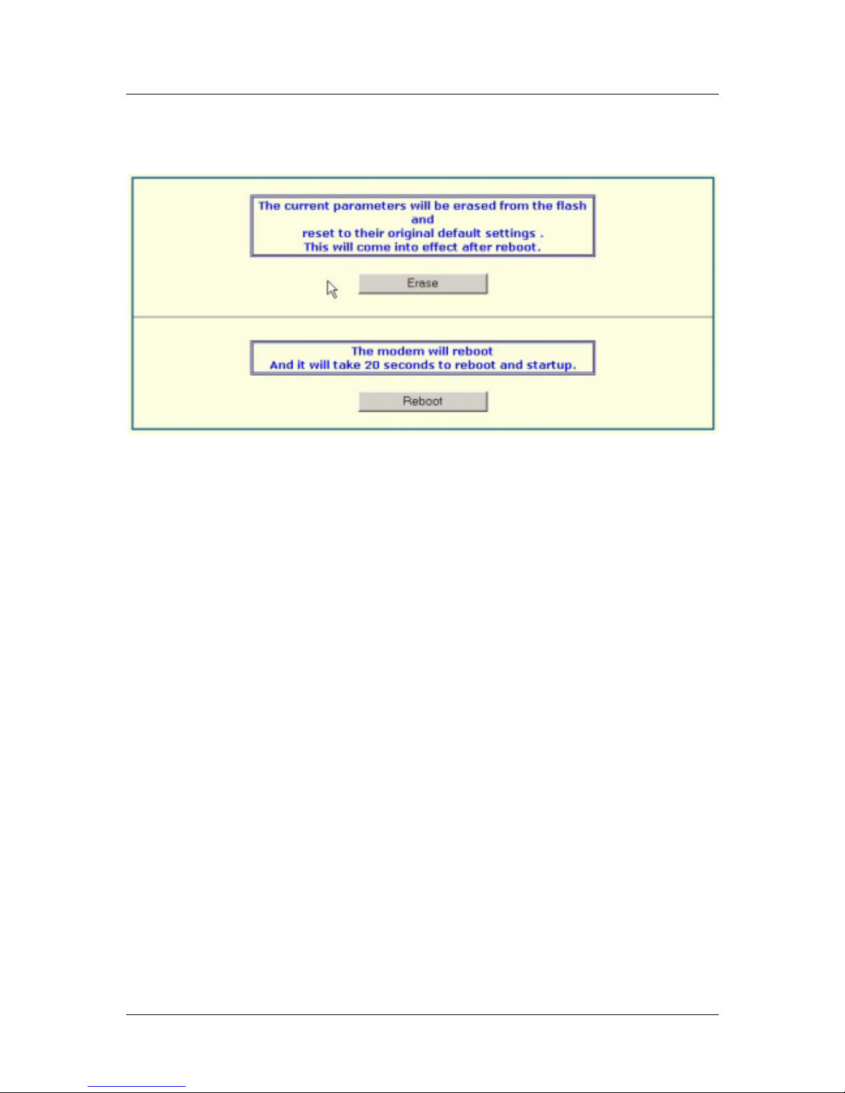
Erase and Reboot
Gives you the option to erase current settings or reboot Router.
31
Page 42
DSL-560I ADSL Router User’s Guide
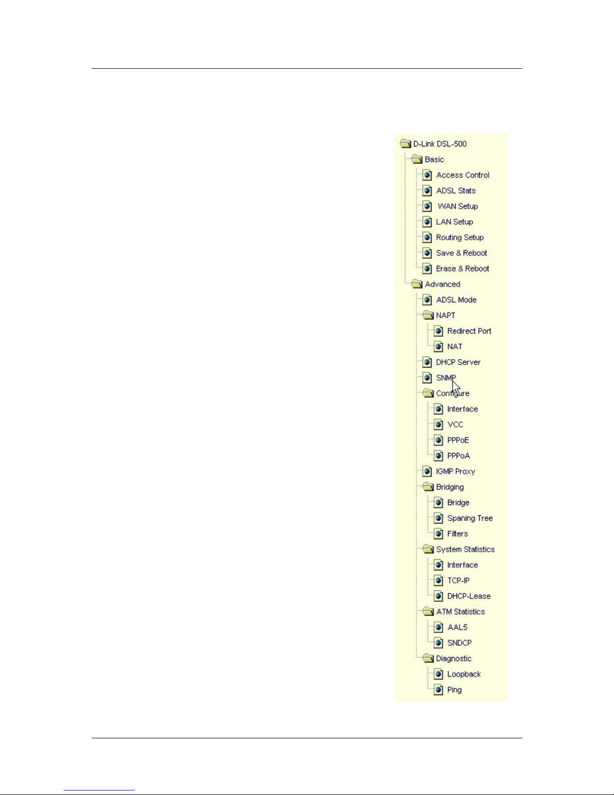
Advanced
The information contained in the Advanced folders are listed as follows:
• ADSL Mode
• Redirect Port
• NAT
• DHCP Server
• SNMP
• Interface
• VCC
• PPPoE
• PPPoA
• IGMP Proxy
• Bridge
• Spanning Tree
• Filters
• Interface
• TCP-IP
• DHCP-Lease
• AAL5
• SNDCP
• Loopback
• Ping
32
Page 43
DSL-560I ADSL Router User’s Guide
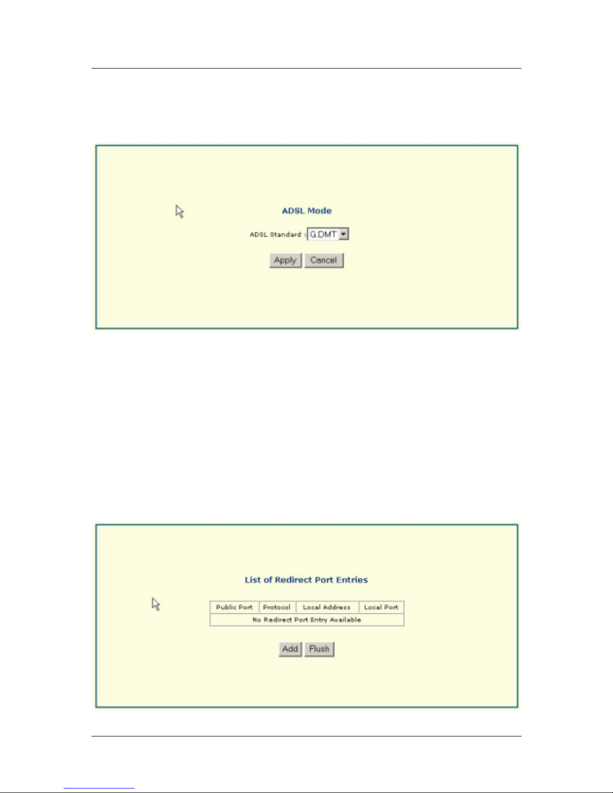
ADSL Mode
Displays modulation technique used for ADSL connection, G.DMT or G.lite. You can change the modulation
technique by selecting the appropriate ADSL Standard and click Apply.
Redirect Port
The Port Redirection feature of the Router is used in conjunction with NAT or IP Masquerading to improve
security and efficiency. Port redirection can be used to direct potentially hazardous packets to a proxy server
outside your firewall. For example, you can configure the Router to dir ect HTTP packets to a designated HTTP
server in the DMZ. Other common applications might include directing incoming SMTP packets to an Email
server for data scrutiny and improved netw ork efficiency.
Port Redirection can be used to redirect TCP or UDP packets to a specified port and a specified IP address on
your local network. You can define a set of instructions for a specific incoming port or for a range of incoming
ports. Each instruction set or rule is indexed and can be modified or deleted later as needed.
33
Page 44
DSL-560I ADSL Router User’s Guide
NAT
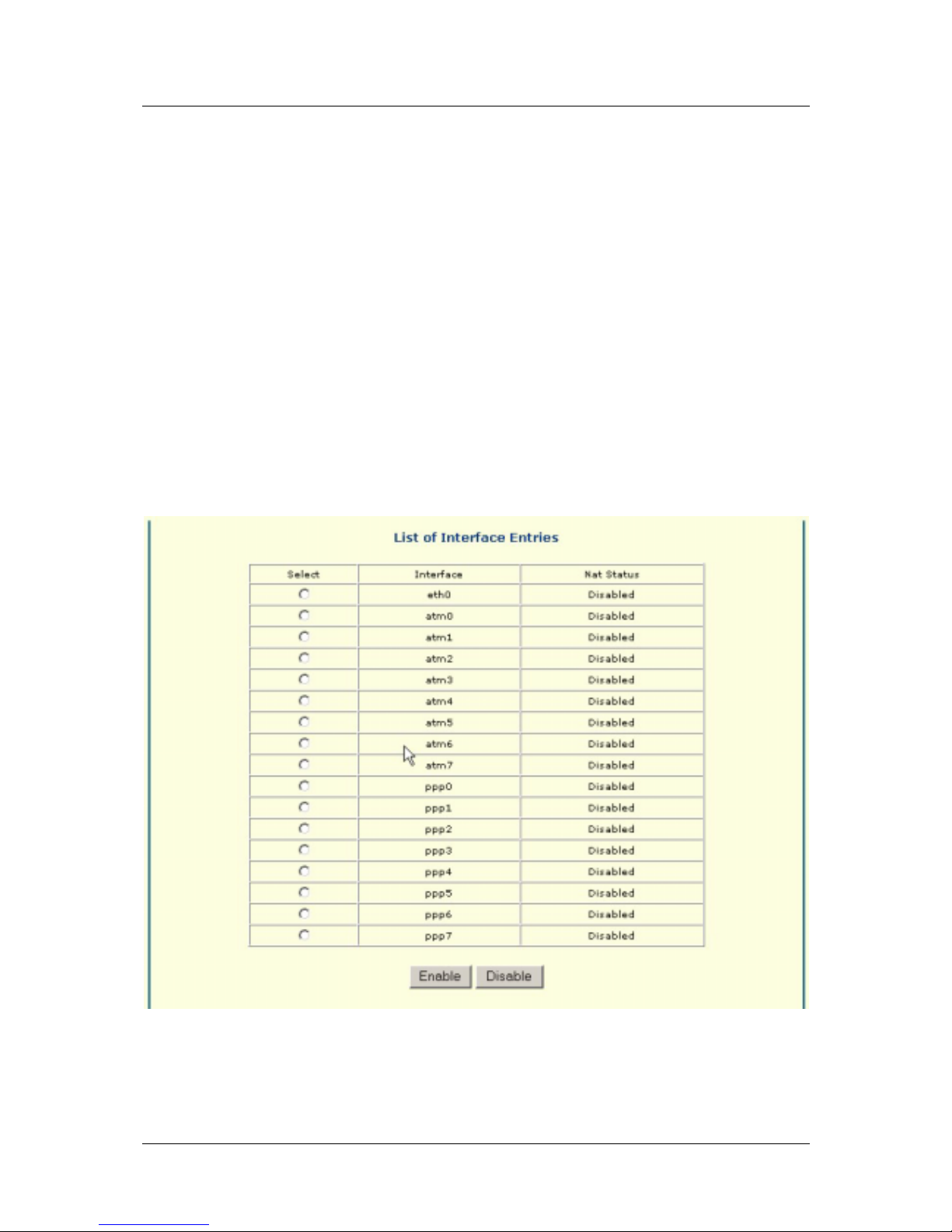
Network Address Translation (NAT) is a routing protocol that allows your network to become a private network
that is isolated from, yet connected to the Internet. It does this by changing the IP address of packets from a
global IP address usable on the Internet to a local IP address usable on your private network (but not on the
Internet) and vice-versa. The Router allows up to 128 host IP addresses.
NAT has two major benefits. First, NAT allows many users to access the Internet using a single global IP
address. This can greatly reduce the costs associated with Internet access and helps alleviate the current shortage
of Internet IP addresses. Secondly, the NAT process creates an added degree of security by hiding your private
network behind one IP address. The NAT function will normally only allow incoming packets that are generated
in response to a request from a host within the LAN.
If your network uses web servers, FTP servers or other proxies used for data requests from outside the private
network, you can use NAT in conjunction with Port Redirection to allow appropriate use of your servers by
outside users. See the section on Port Redirection for more information.
For the purposes of network administration, NAT is almost indispensable. Hosts and servers on the internal
network can be moved easily. Using NAT together with DHCP can greatly reduce the workload of a network
manager while allowing tremendous flexibility.
Select the Interface entry to enable or disable.
34
Page 45
DSL-560I ADSL Router User’s Guide
DHCP Server
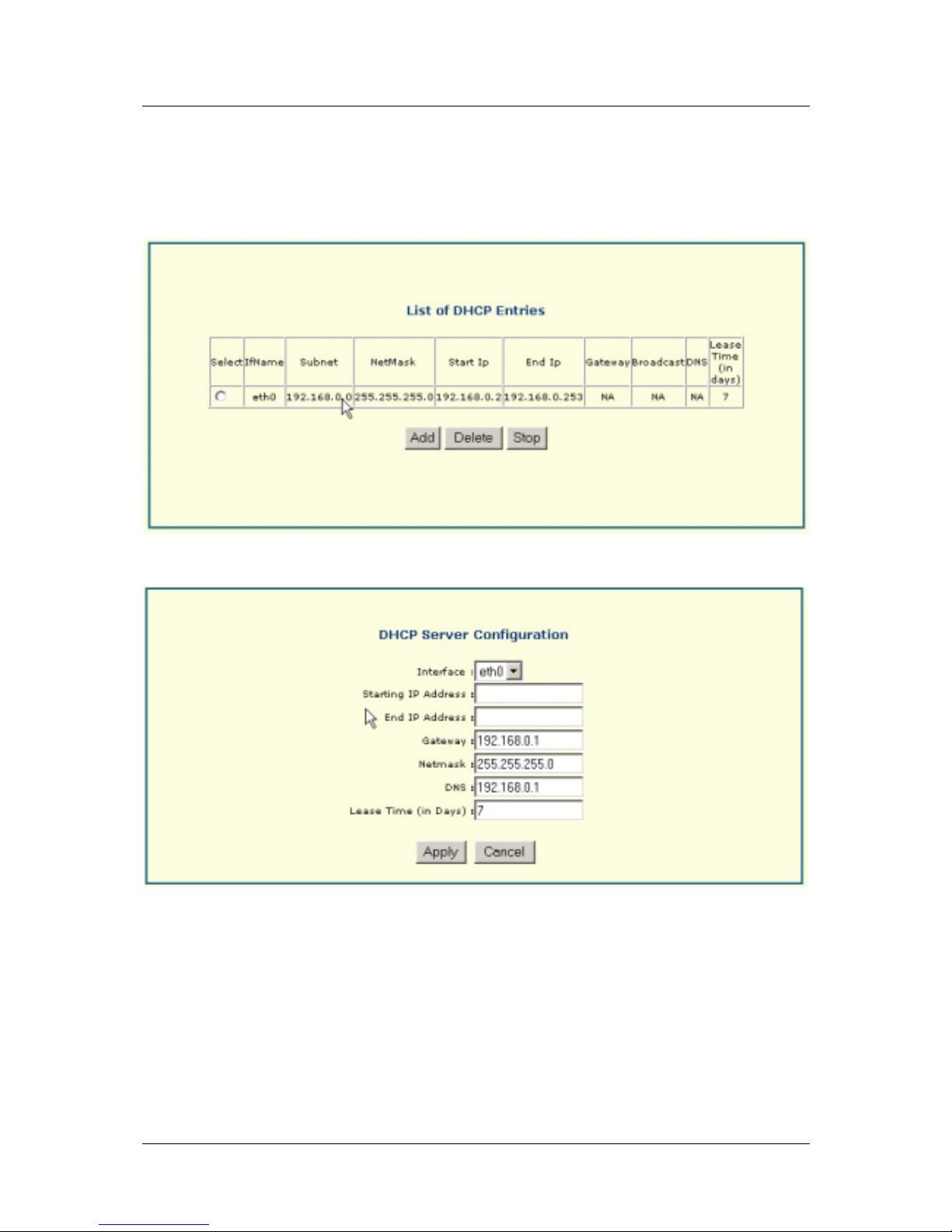
Use the DHCP Server menu to configure the Router to act as a DHCP server for the LAN. This menu lists
DHCP Entries.
To add another entry click Add and enter the appropriate settings—IfName, Subnet mask, NetMask, StartIp, End
Ip, Gateway, Broadcast, DNS, Lease Time.
To delete a DHCP entry, simply select the entry and click Delete.
35
Page 46
DSL-560I ADSL Router User’s Guide
SNMP
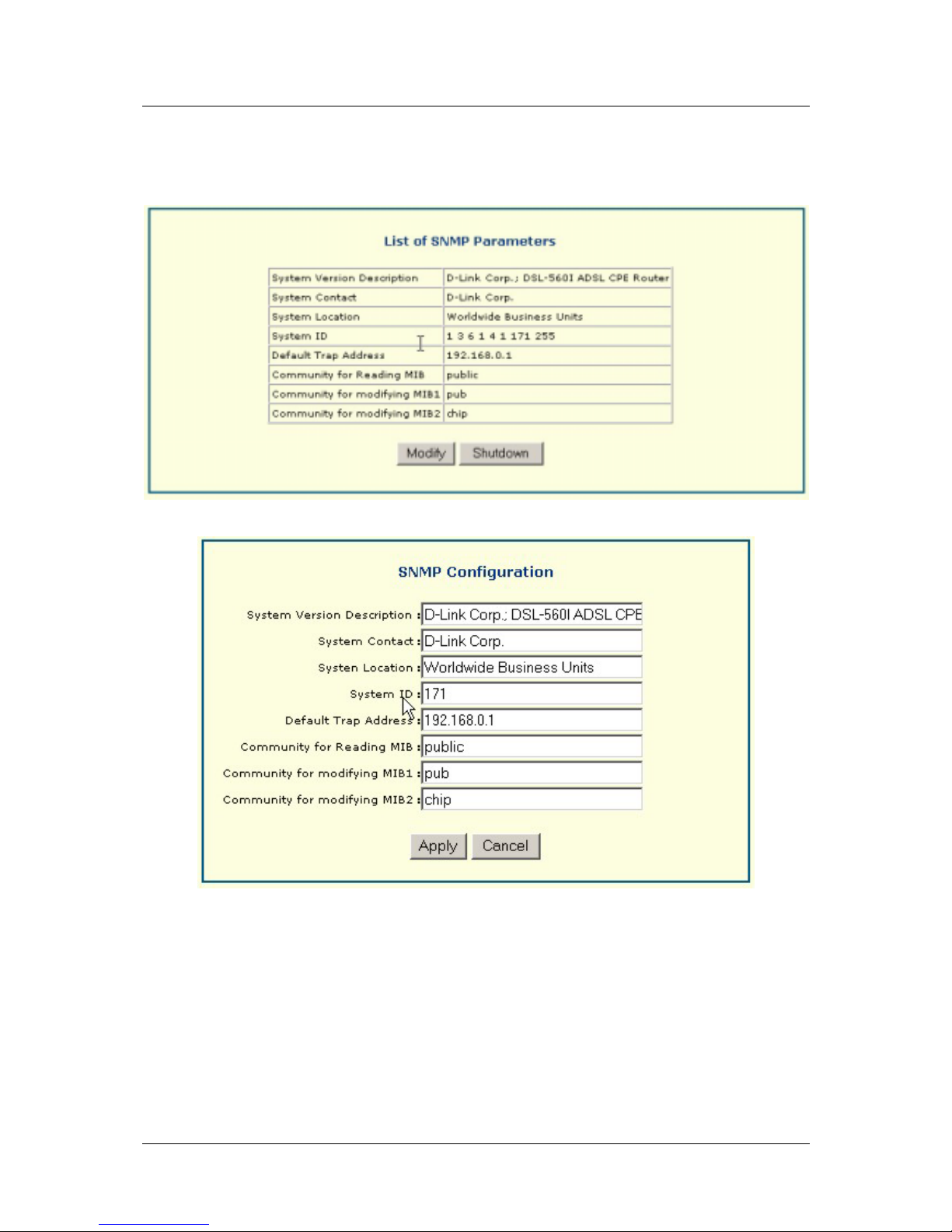
This menu lists SNMP parameters.
You may modify by clicking Modify and entering the appropriate settings.
36
Page 47
DSL-560I ADSL Router User’s Guide
Interface
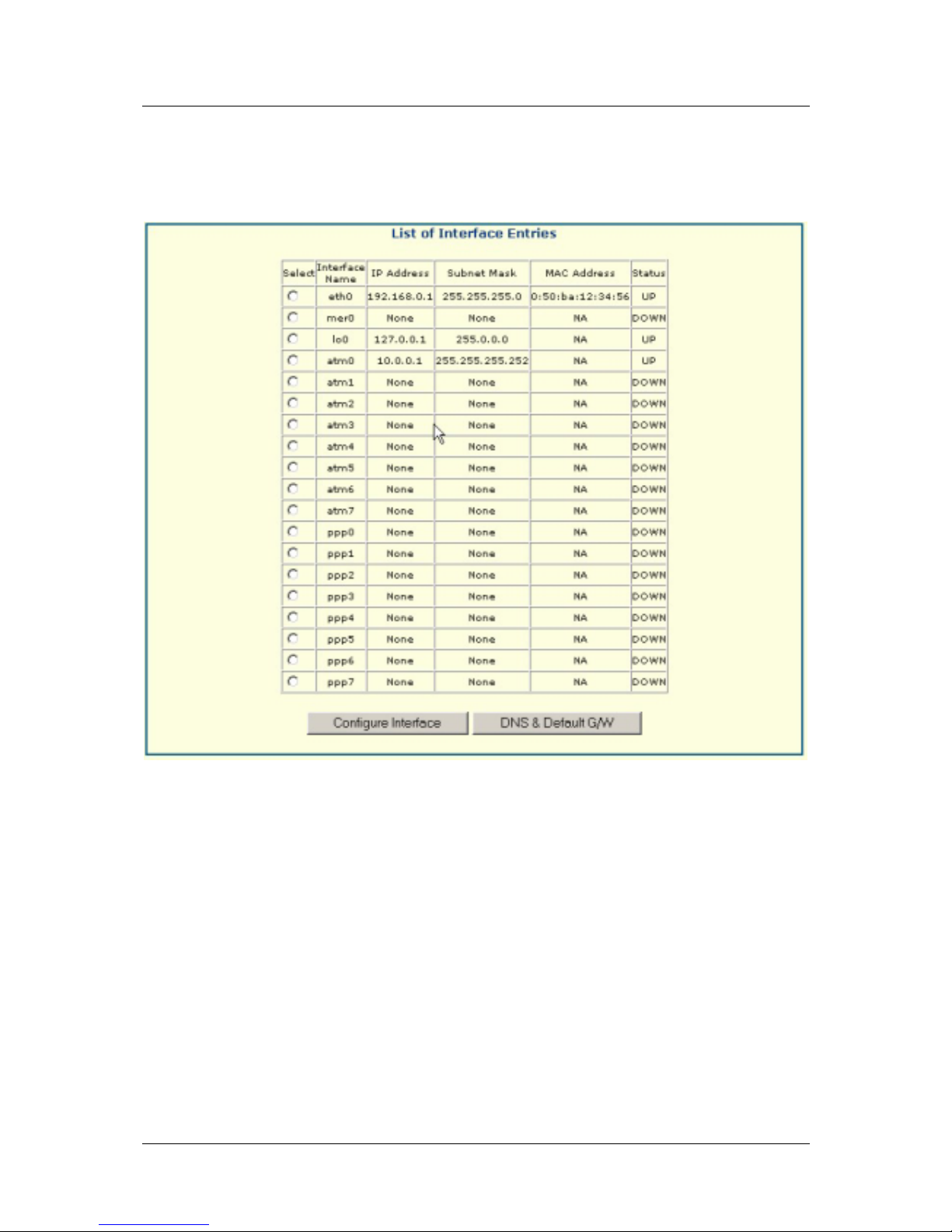
This menu gives a list of interface entries. For each entry an IP address, subnet mask, MAC address and status
are given.
37
Page 48
DSL-560I ADSL Router User’s Guide
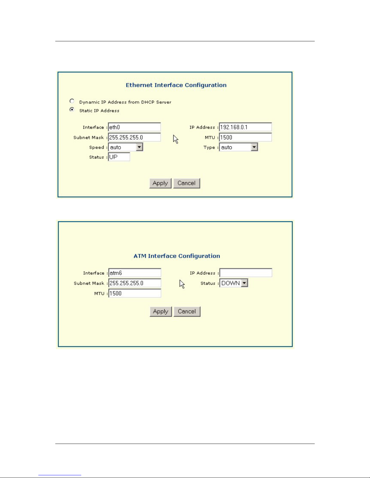
To configure interface, select interface entry and click on Configure Interface. A screen such as the one below
should appear for an Ethernet Interface Configuration.
Each interface is configured in its own separate screen. For an ATM Interface Configuration a screen such as
the one below will appear.
38
Page 49
DSL-560I ADSL Router User’s Guide
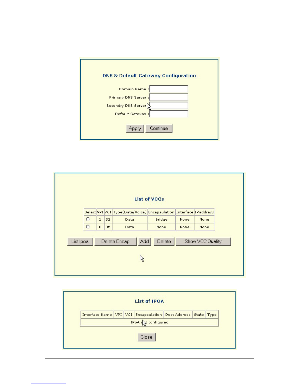
To configure your DNS & Default Gateway, click on DNS & Default G/W. A screen su ch as the one below
will appear. Enter the appropriate settings.
VCC
This menu provides a list of VCCs.
Click List Ipoa to bring up a list of IPOAs that are configured.
39
Page 50
DSL-560I ADSL Router User’s Guide
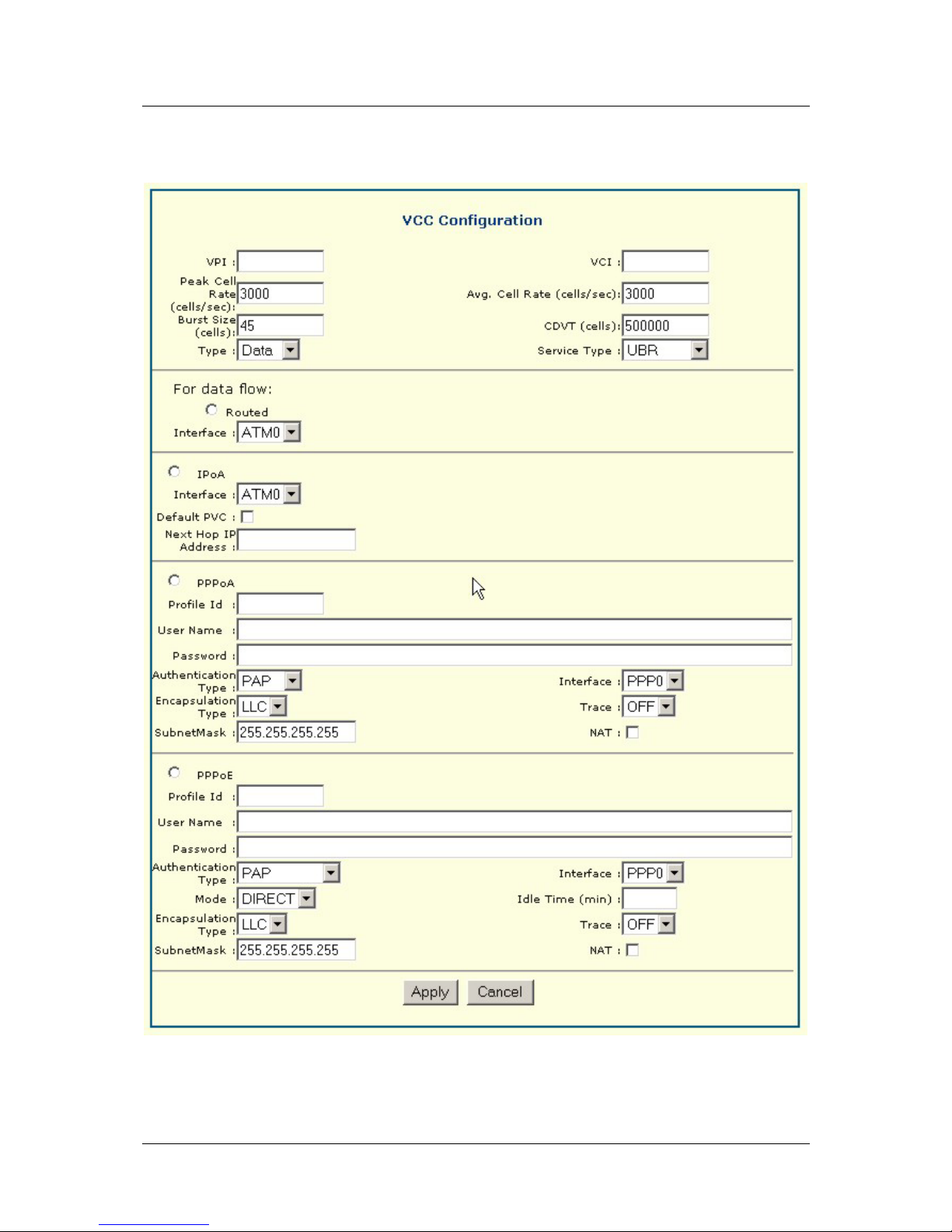
To configure a VCC click on Add. The following screen will appear. Enter the information requested and click
Apply. To delete simply select the VCC you wish to delete and click Delete.
40
Page 51
DSL-560I ADSL Router User’s Guide
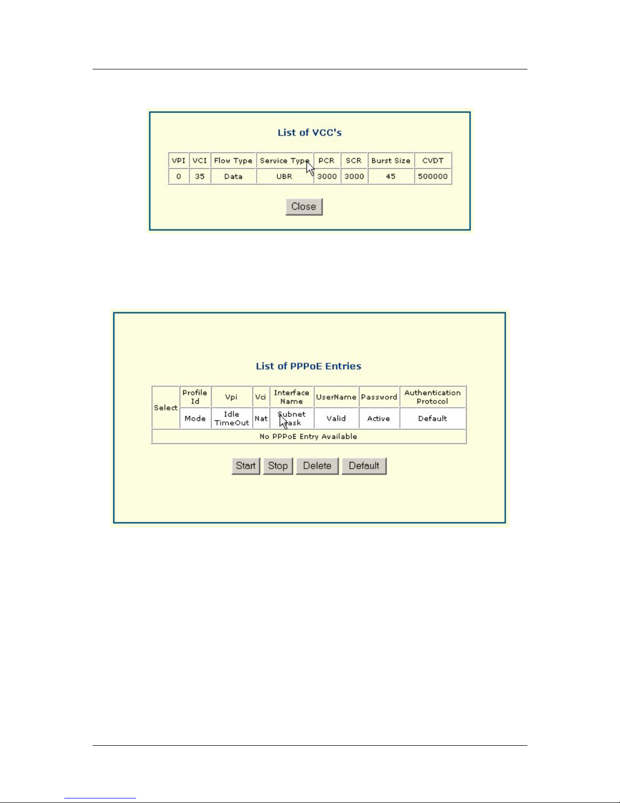
Click on Show VCC Quality to display the screen below.
PPPoE
This menu lists PPPoE Entries. Click Start to initiate the process. Click Stop to terminate the process. You
may delete an entry by clicking Delete. PPPoE entries are entered in the Wan Setup page.
41
Page 52
DSL-560I ADSL Router User’s Guide
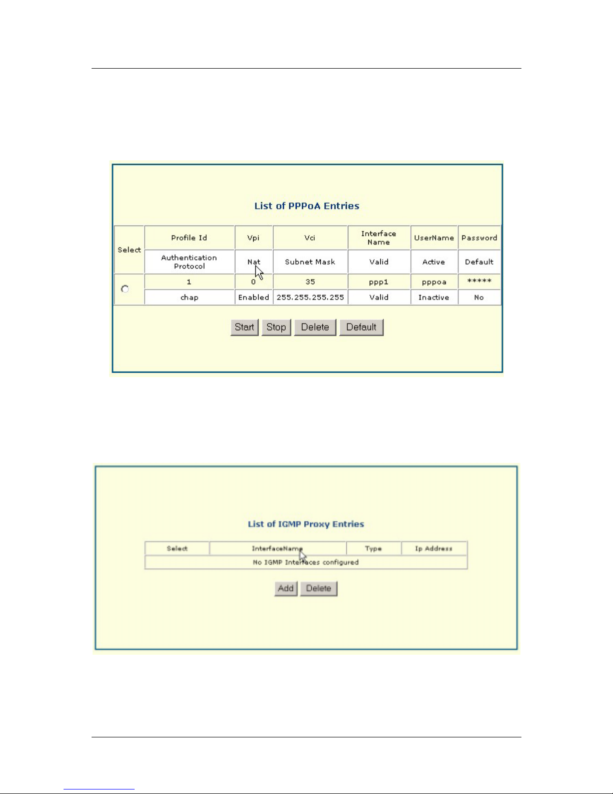
PPPoA
This menu lists PPPoA connections. Click Start to initiate the process. Click Stop to terminate the process.
You may delete an entry by clicking Delete. PPPoA entries are entered in the Wan Setup page.
IGMP Proxy
This menu lists IGMP Proxy entries.
42
Page 53
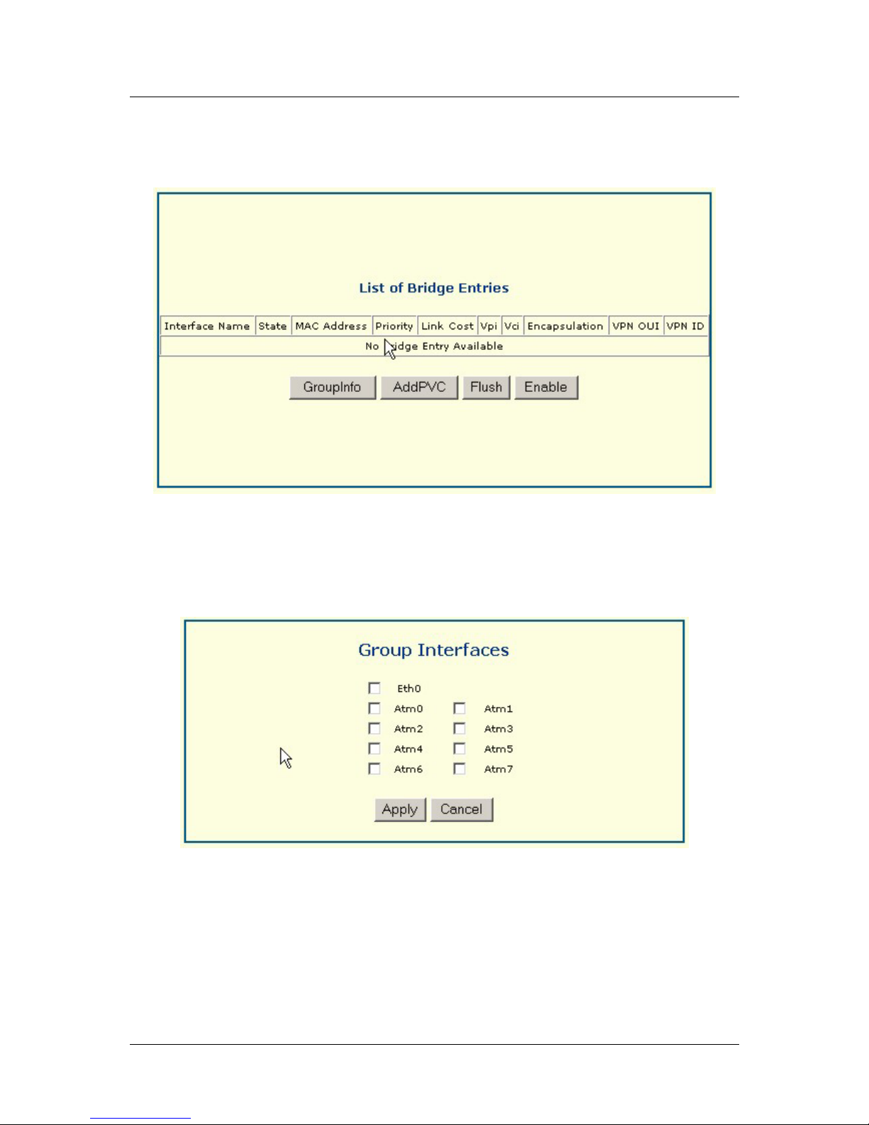
DSL-560I ADSL Router User’s Guide
Bridge
This menu lists bridge entries.
Click on GroupInfo to bring up Group Interfaces window. Click on interfaces to select them and then click on
Apply to put them into effect.
43
Page 54
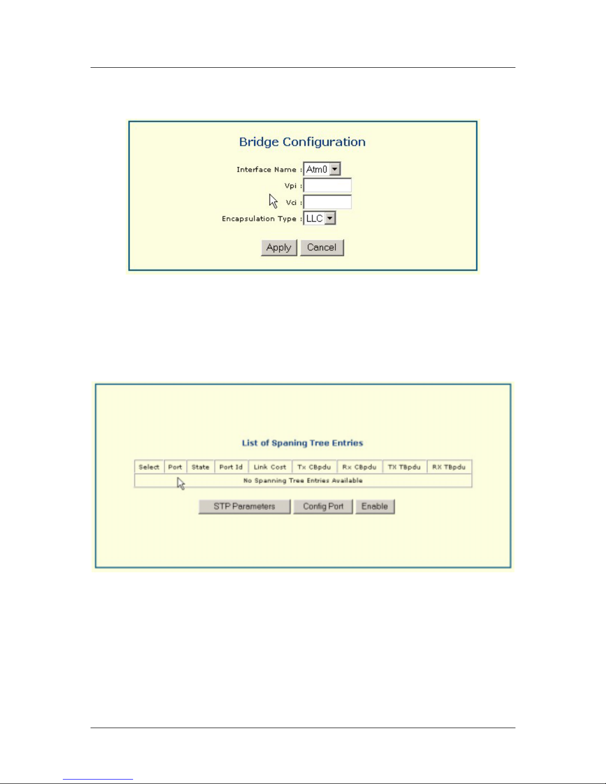
DSL-560I ADSL Router User’s Guide
Click on AddPVC to bring up the following Bridge Configuration menu. Enter the interface name, vpi settings,
vci settings, and encapsulation type. Then click Apply to place configuration into effect.
Spanning Tree
This menu provides a list of spanning tree entries.
44
Page 55
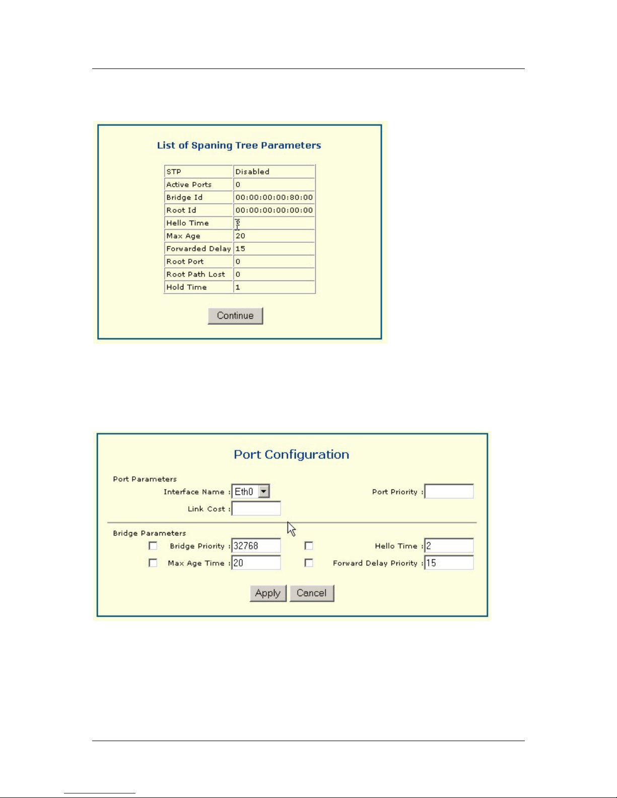
DSL-560I ADSL Router User’s Guide
Click on STP Parameters to bring up read-only window List of Spanning Tree Parameters. Click Continue to
proceed.
Click ConfigPort to bring up Port Configuration window below. Enter settings and click Apply to put settings
into effect.
45
Page 56
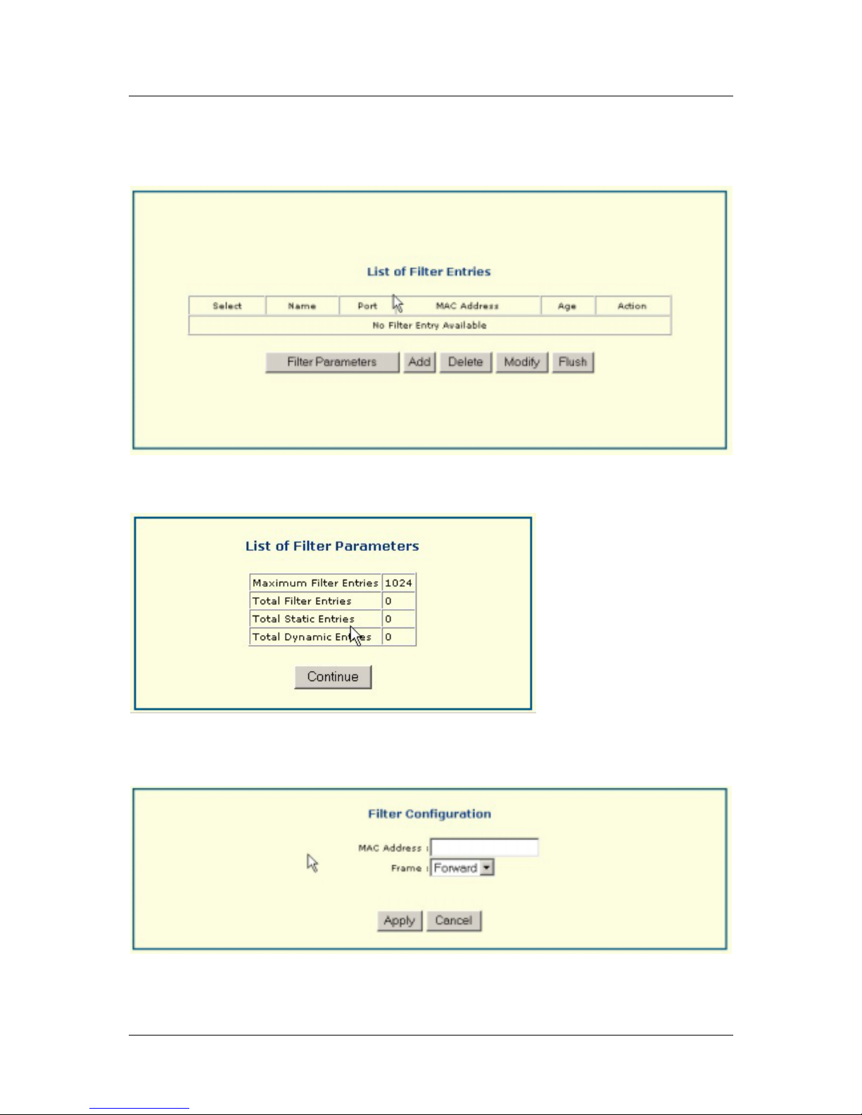
DSL-560I ADSL Router User’s Guide
Filter
This menu displays a list of filter entries.
Click on Filter Parameters to bring up read-only List of Filter Parameters.
Click on Add to configure filter by entering a MAC address and Frame option. Click Apply to place settings
into effect.
46
Page 57
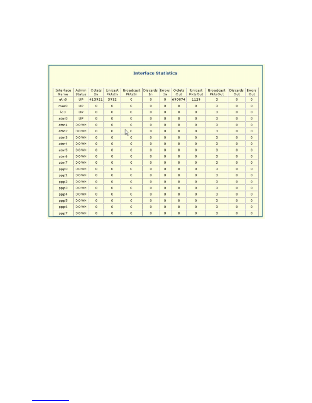
DSL-560I ADSL Router User’s Guide
Interface
This menu gives a read-only list of interface statistics ordered by interface name.
47
Page 58
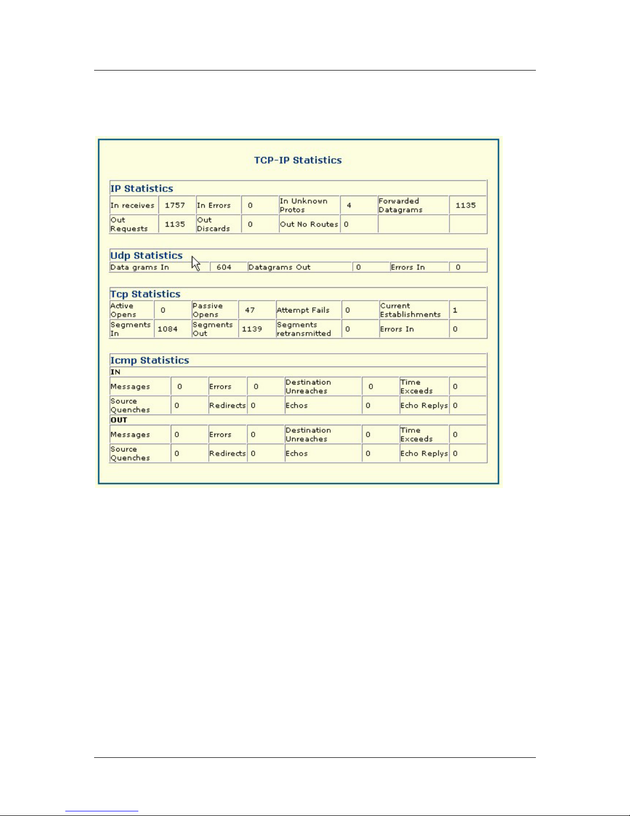
DSL-560I ADSL Router User’s Guide
TCP-IP
This menu provides TCP-IP Statistics.
48
Page 59
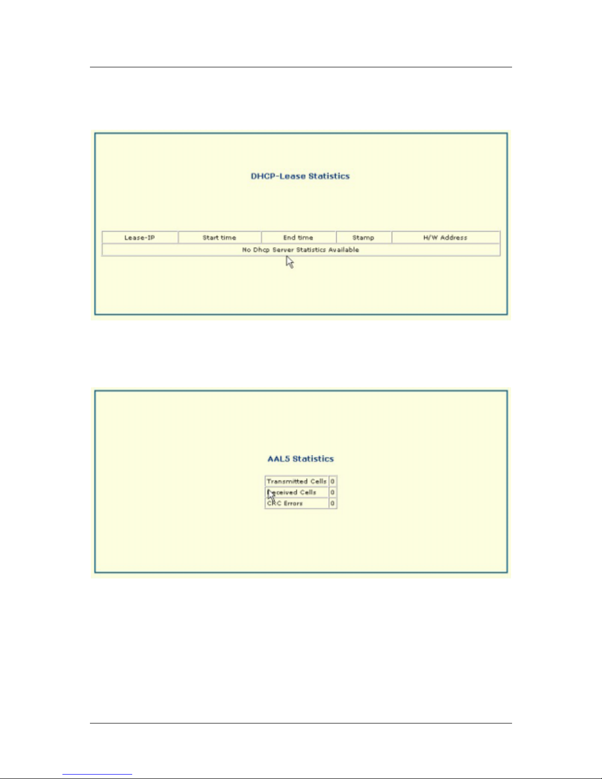
DSL-560I ADSL Router User’s Guide
DHCP-Lease
This menu gives DHCP-Lease Statistics.
AAL5
This menu gives AAL5 Statistics.
49
Page 60
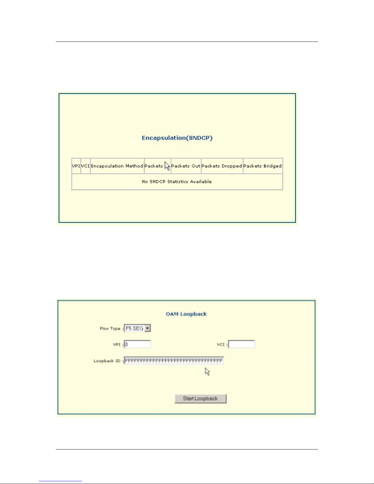
DSL-560I ADSL Router User’s Guide
SNDCP
This menu gives SNDCP statistics.
Loopback
This menu item allows the user to perform an OAM Loopback by entering Flow Type, VPI settings, VCI
settings, and Loopback ID. Click Start Loopback to initiate loopback test.
50
Page 61
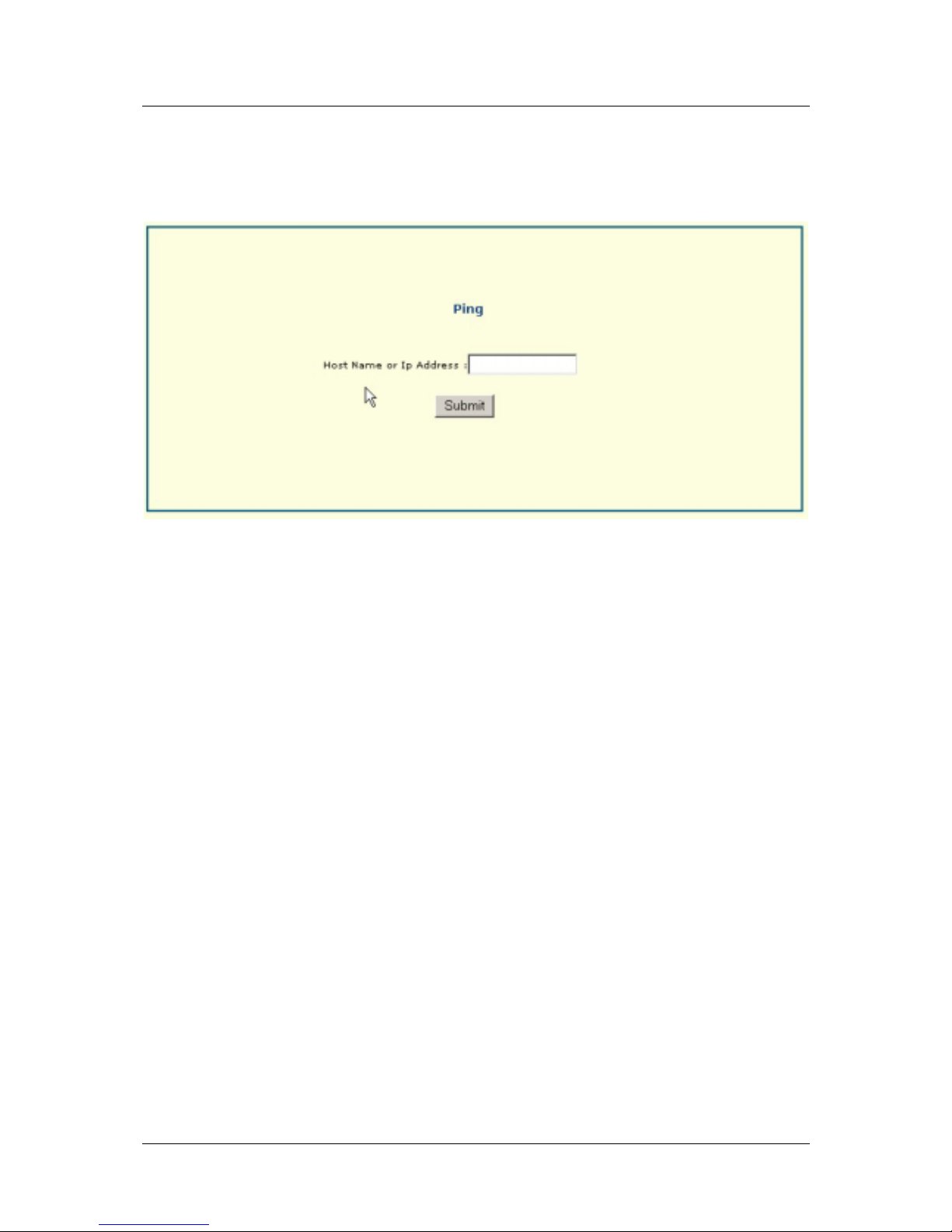
DSL-560I ADSL Router User’s Guide
Ping
This menu allows the user to perform a Ping test by entering the host name or IP address. Click Submit to
initate ping.
51
Page 62
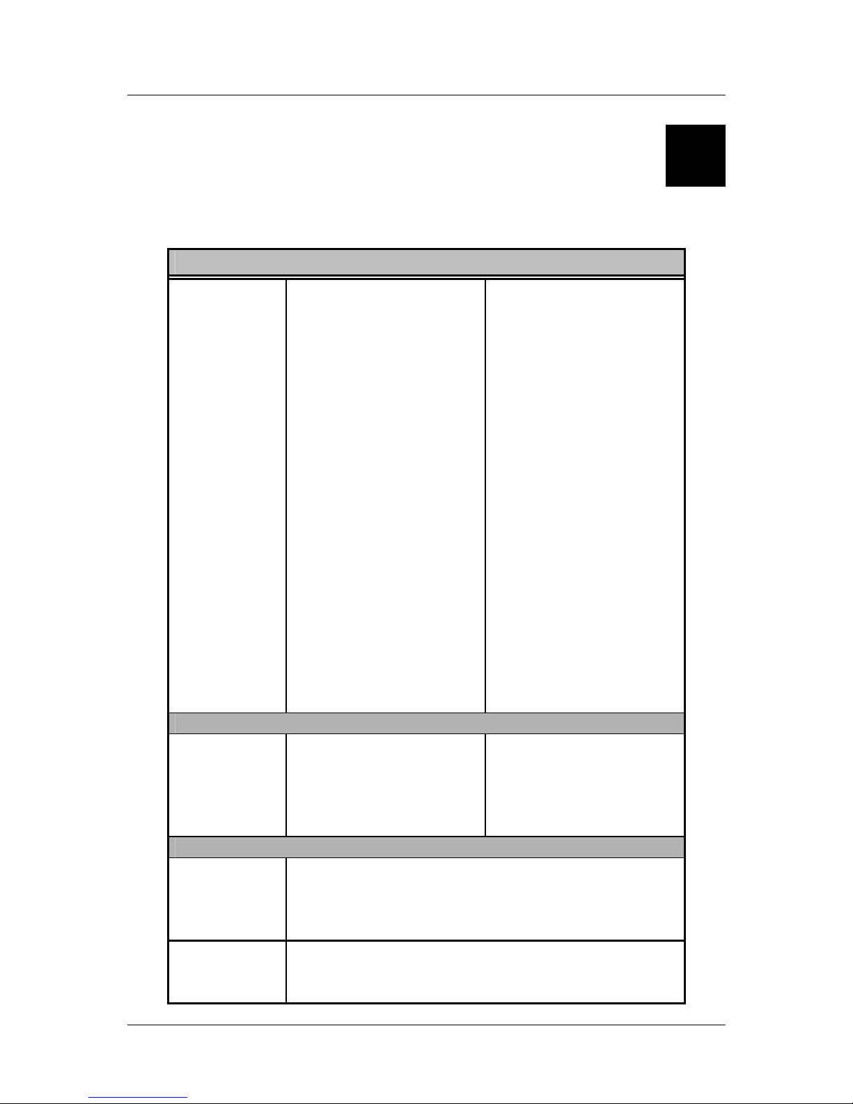
DSL-560I ADSL Router User’s Guide
A
Technical Specifications
GENERAL
STANDARDS:
• ITU G.992.1 (G.dmt)
• ITU G.992.2 (G.lite)
• ITU G.994.1 (G.Hs)
• ITU-T Rec. I.361
• ITU-T Rec. I.610
• IEEE 802.3
• IEEE 802.3u
• IEEE 802.1d
• RFC 791 (IP Routing)
• RFC 792 (UDP)
• RFC 826 (ARP)
• RFC 1058 (RIP 1)
• RFC 1389 (RIP 2)
• RFC 1213 compliant
• RFC 1483 (Bridged
Ethernet)
• RFC 1577 (IP over
ATM)
• RFC 1661 (PPP)
• RFC 1994 (CHAP)
• RFC 1334 (PAP)
• RFC 2364 (PPP over
ATM)
• RFC 1631 (NAT)
• RFC 1877 (Automatic
IP assignment)
• RFC 2516 (PPP over
Ethernet)
• Supports RFC 2131
and RFC 2132 (DHCP)
• Compatible with all
T1.413 issue 2 (full rate
DMT over analog
POTS), and CO
DSLAM equipment
• Supports ATM Forum
UNI V3.1 PVC
PROTOCOLS:
TCP/IP
UDP
RIP-1
RIP-2
IGMP
DHCP
BOOTP
ARP
AAL5
DATA
TRANSFER
RATE:
G.dmt full rate: Downstream up to 8 Mbps
Upstream up to 640 Kbps
G.lite: Downstream up to 1.5 Mbps
Upstream up to 512 Kbps
MEDIA
INTERFACE
EXCHANGE:
RJ-11 port ADSL telephone line connection
RJ-45 port for 10BASET Ethernet connection
RJ-14 console port for local configuration (requires adapter)
52
Page 63
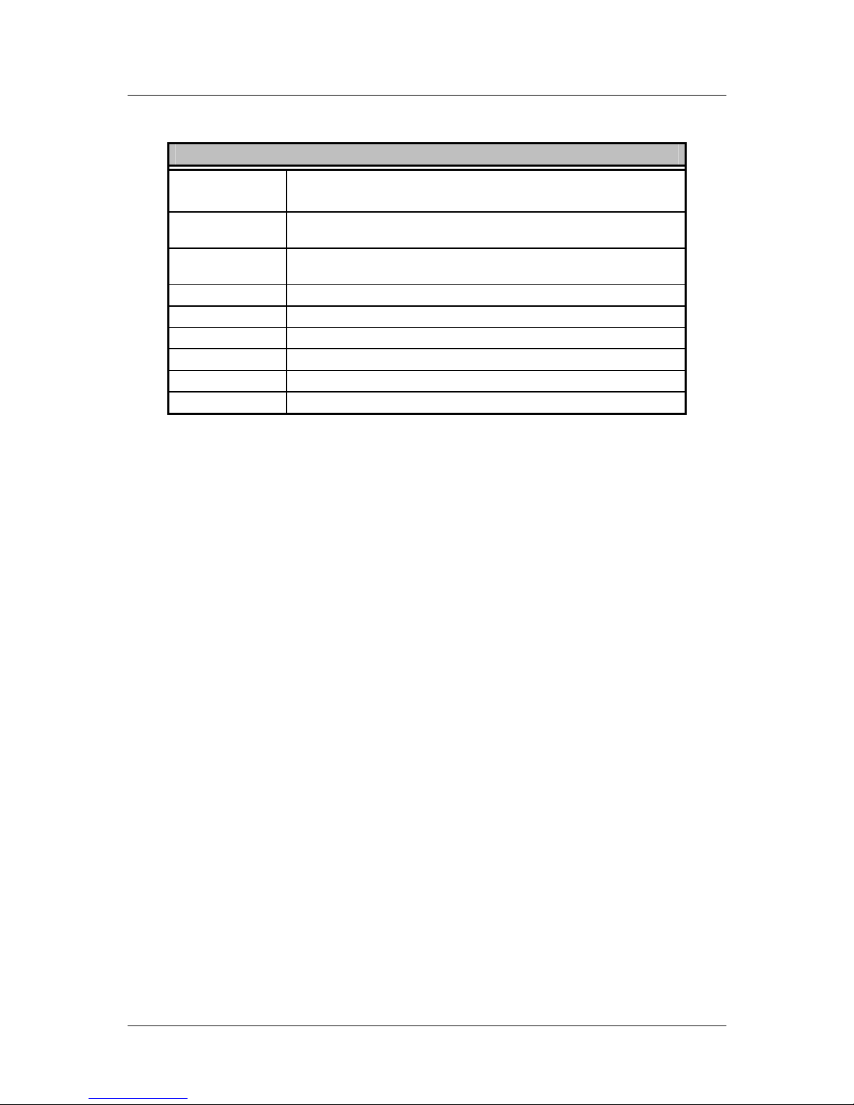
DSL-560I ADSL Router User’s Guide
Physical and Environmental
DC inputs:
Power Adapter:
Input: 100V ~ 240V AC 50 ~ 60Hz
Output: 7.5V DC, 1.5A
Power
Consumption:
5 Watts (max)
Operating
Temperature:
5° to 40° C
Humidity: 5 to 95% (non-condensing)
Dimensions: 190 mm x 116.8 mm x 30.9 mm
Weight: 360 gm
EMI:
CE Class B
Safety: CSA International
Reliability: Mean Time Between Failure (MTBF) min. 4 years
53
Page 64

DSL-560I ADSL Router User’s Guide
B
LAN IP Setup
The DSL-560I is designed to provide network administrators maximum flexibility for IP addressing on the
Ethernet LAN. The easiest IP setup choice in most cases is to let the Router do it using DHCP, which is enabled
by default. This appendix briefly describes various op tions including DHCP, used for IP setup on a LAN. If you
are new to IP networking, the next appendix provides some background information on basic IP concepts.
Assigning Network IP Addresses
The IP address setting s, which in clud e the IP ad dres s, subne t mask and gatew ay IP add ress ar e the f irs t and mos t
important internal network settings that need to be configured. The Router is assigned a default LAN IP address
and subnet mask. If you do not have a preexisting IP network and are setting one up now, using the factory
default IP address settings can greatly ease the setup process. If you already have a preexisting IP network, you
can adjust the IP settings for the Router to fit within your existing scheme.
Using the Default IP Address
The Router is shipped with a preset default IP address setting of 192.168.0.1 for the LAN port. There are two
ways to use this default IP address, you can manually assign an IP address and subnet mask for each PC on the
LAN or you can instruct the Router to automatically assign them using DHCP. The simplest method is to use
DHCP. The DHCP function is active by default.
Manual IP Address Assignment
Manually configuring IP settings for the LAN means you must manually set an IP address, subnet mask and IP
address of the default gateway (the Router’s IP address) on each networked computer. The example listed below
describes IP configuration for computers running W indows 98 or Windows 95. Regardless of what operating
system is used on each workstation, the three network IP settings must be defined so the network interface used
by each workstation can be identified by the Router, and vice versa. For detailed information about configuring
your workstations IP settings, consult the user’s guide included with the operating system or the network
interface card (NIC).
1. In Windows 95/98, click on the START button, go to Settings and choose Control Panel.
2. In the window that opens, double-click on the Network icon.
3. Under the Configuration tab, select the TCP/IP component and click Properties.
4. Choose the Specify an IP address option and edit the address settings accordingly. Consult the table below
for IP settings on a Class C network.
Using Default IP without DHCP
Host IP Address Subnet Mask Gateway IP
Router
192.168.0.1 255.255.255.0
Computer #1
192.168.0.2 255.255.255.0 192.168.0.1
Computer #2
192.168.0.3 255.255.255.0 192.168.0.1
Computer #3
192.168.0.4 255.255.255.0 192.168.0.1
LAN IP Setup - Example #1
54
Page 65
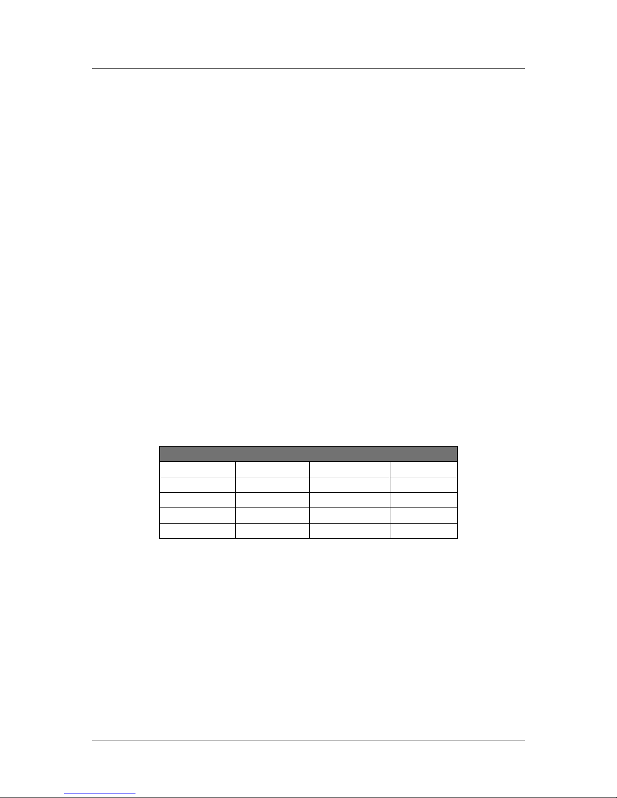
DSL-560I ADSL Router User’s Guide
Please note that when using the default IP address as in the above example, the first three numbers in the IP
address must always be the same with only the fourth number changing. The first three numbers define the
network IP address (all machines must belong to the same IP network), while the last number denotes the host IP
address (each computer must have a unique address to distinguish it on the network). The IP address scheme
used in Example #1 can be used for any LAN that requires up to 253 separate IP addresses (excluding the
Router). Notice that the subnet mask is the same for all machines and the default gateway address is the LAN IP
address of the Router.
It is a good idea to make a note of each device’s IP address for reference during troubleshooting or when adding
new stations or devices.
Using DHCP
The second way to use the default settings is to allow the Router to automatically assign IP settings for
workstation using DHCP. To do this, simply make sure your computers’ IP addresses are set to 0.0.0.0 (under
Windows, choose the option Obtain an IP address automatically in the TCP/IP network component described
above). When the computers are restarted, their IP settings will automatically be assigned by the Router. The
Router is set by default to use DHCP. See the discussion in Chapter 5 for information on how to use configure
the Router for DHCP.
Changing the IP Address of the Router
When planning your LAN IP address setup, you may use any scheme allowed by rules that govern IP assignment.
It may be more convenient or easier to remember an IP scheme that use a different address for the Router. Or
you may be installing the Router on a network that has already established the IP settings. Changing the IP
address is a simple matter and can be done using the web manager (see LAN IP Address in Chapter 5). If you are
incorporating the Router into a LAN with an existing IP structure, be sure to disable the DHCP function. Also,
consider the effects of the NAT function which is enable by default.
An IP addressing scheme commonly used for Ethernet LANs establishes 10.0.0.1 as the base address for the
network. Using Example #2 below, the Router is assigned the base address 10.0.0.1 and the remaining addresses
are assigned manually or using DHCP.
Alternative IP Assignment
Host IP Address Subnet Mask Gateway IP
Router
10.0.0.1 255.255.255.0
Computer #1
10.0.0.2 255.255.255.0 192.168.0.1
Computer #2
10.0.0.3 255.255.255.0 192.168.0.1
Computer #3
10.0.0.4 255.255.255.0 192.168.0.1
LAN IP Setup - Example #2
These two examples are only examples you can use to help you get started. If you are interested in more
advanced information on how to use IP addressing on a LAN there are numerous resources freely available on
the Internet. There are also many books and chapters of books on the subject of IP address assignment, IP
networking and the TCP/IP protocol suite.
55
Page 66
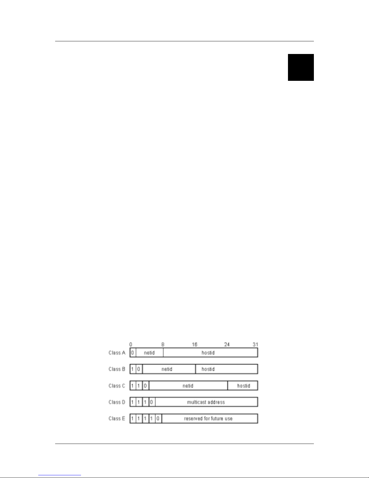
DSL-560I ADSL Router User’s Guide
C
IP Concepts
This appendix describes some basic IP concepts, the TCP/IP addressing scheme and show how to assign IP
Addresses.
When setting up the Router, you must make sure it has a valid IP address. Even if you will not use the WAN port
(ADSL port), you should, at the very least, make sure the Ethernet LAN port is assigned a valid IP address. This
is required for telnet, in-band SNMP management, and related functions such as “trap” handling and TFTP
firmware download.
IP Addresses
The Internet Protocol (IP) was designed for routing data between network sites all over the world, and was later
adapted for routing data between networks within any site (often referred to as “subnetworks” or “subnets”). IP
includes a system by which a unique number can be assigned to each of the millions of networks and each of the
computers on those networks. Such a number is called an IP address.
To make IP addresses easy to understand, the originators of IP adopted a system of representation called “dotted
decimal” or “dotted quad” notation. Below are examples of IP addresses written in this format:
201.202.203.204 189.21.241.56 125.87.0.1
Each of the four values in an IP address is the ordinary decimal (base 10) representation of a value that a
computer can handle using eight “bits” (binary digits — 1s and 0s). The dots are simply convenient visual
separators.
Zeros are often used as placeholders in dotted decimal notation; 189.21.241.56 can therefore also appear as
189.021.241.056.
IP networks are divided into three classes on the basis of size. A full IP address contains a network portion and a
“host” (device) portion. The network and host portions of the address are different lengths for different classes of
networks, as shown in the table below.
56
Page 67
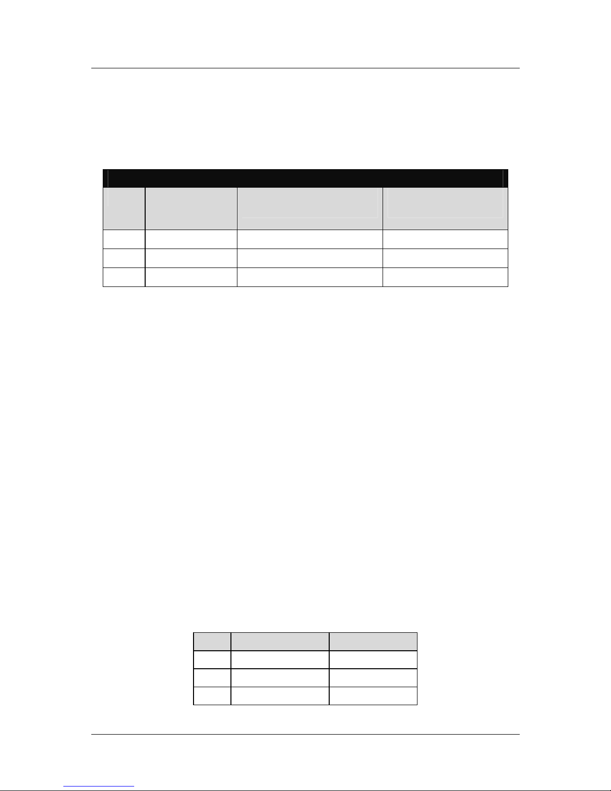
DSL-560I ADSL Router User’s Guide
Networks attached to the Internet are assigned class types that determine the maximum number of possible hosts
per network. The previous figure illustrates how the net and host portions of the IP address differ among the
three classes. Class A is assigned to networks that have more than 65,535 hosts; Class B is for networks that
have 256 to 65534 hosts; Class C is for networks with less than 256 hosts.
IP Network Classes
Class Maximum Number
of Networks in
Class
Network Addresses (Host
Portion in Parenthesis)
Maximum Number of
Hosts per Network
A 126 1(.0.0.0) to 126(.0.0.0) 16,777,214
B 16,382 128.1(.0.0) to 191.254(.0.0) 65,534
C 2,097,150 192.0.1(.0) to 223.255.254(.0) 254
Note: All network addresses outside of these ranges (Class D and E) are either reserved or set aside for
experimental networks or multicasting.
When an IP address's host portion contains only zero(s), the address identifies a network and not a host. No
physical device may be given such an address.
The network portion must start with a value from 1 to 126 or from 128 to 223. Any other value(s) in the network
portion may be from 0 to 255, except that in class B the network addresses 128.0.0.0 and 191.255.0.0 are
reserved, and in class C the network addresses 192.0.0.0 and 223.25 5.255.0 are reserved.
The value(s) in the host portion of a physical device's IP address can be in the range of 0 through 255 as long as
this portion is not all-0 or all-255. Values outside the range of 0 to 255 can never appear in an IP address (0 to
255 is the full range of integer values that can be expressed with eight bits).
The network portion must be the same for all the IP devices on a discrete physical network (a single Ethernet
LAN, for example, or a WAN link). The host portion must be different for each IP device — or, to be more
precise, each IP-capable port or interface — connected directly to that network.
The network portion of an IP address will be referred to in this manual as a network number; the host portion
will be referred to as a host number.
To connect to the Internet or to any private IP network that uses an Internet-assigned network number, you must
obtain a registered IP network number from an Internet-authorized network information center. In many
countries you must apply through a government agency, however they can usually be obtained from your
Internet Service Provider (ISP).
If your organization's networks are, and will always remain, a closed system with no connection to the Internet
or to any other IP network, you can choose your own network numbers as long as they conform to the above
rules.
If your networks are isolated from the Internet, e.g. only between your two branch offices, you can assign any IP
Addresses to hosts without problems. However, the Internet Assigned Numbers Authority (IANA) has reserved
the following three blocks of IP Addresses specifically for private (stub) networks:
Class Beginning Address Ending Address
A 10.0.0.0 10.255.255.255
B 172.16.0.0 172.31.255.255
C 192.168.0.0 192.168.255.255
57
Page 68
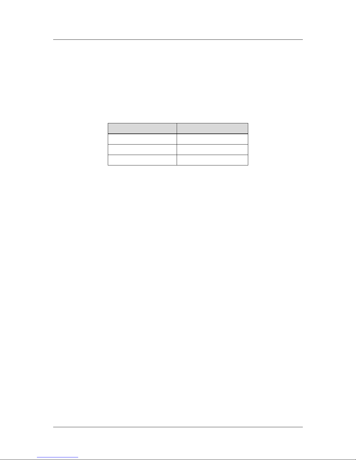
DSL-560I ADSL Router User’s Guide
It is recommended that you choose private network IP Addresses from the above list. For
more information on address assignment, refer to RFC 1597, Address Allocation for Private
Internets and RFC 1466, Guidelines for Management of IP Address Space.
Subnet Mask
In the absence of subnetworks , standard TCP/IP addressing may be used by specifying subnet masks as shown
below.
IP Class Subnet Mask
Class A 255.0.0.0
Class B 255.255.0.0
Class C 255.255.255.0
Subnet mask settings other than those listed above add significance to the interpretation of bits in the IP address.
The bits of the subnet mask correspond directly to the bits of the IP address. An y bit an a subnet mask that is to
correspond to a net ID bit in the IP address must be set to 1.
58
Page 69
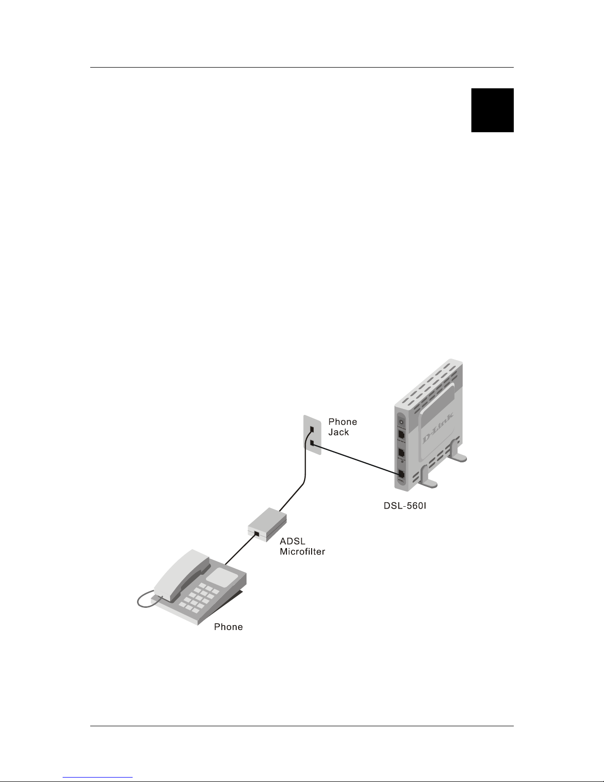
DSL-560I ADSL Router User’s Guide
D
Microfilters and Splitters
Most ADSL clients will be required to install a simple device that prevents the ADSL line from interfering with
regular telephone services. These devices are commonly referred to as microfilters or sometimes called
(inaccurately) line splitters. They are easy to install and use standard telephone connectors and cable.
Some ADSL service providers will send a telecommunications technician to modify the telephone line, usually
at the point where the telephone line enters the building. If a technician has divided or split your telephone line
into two separate lines - one for regular telephone service and the other for ADSL – then you do not need to use
any type of filter device. Follow the instructions given to you by your ADSL service prov ider about where and
how you should connect the Modem to the ADSL line.
Microfilters
Unless you are instructed to use a “line splitter” (see below), it will be necessary to install a microfilter (low pass
filter) device for each telephone or telephone device (answering machines, Faxes etc.) that share the line with the
ADSL service. Microfilters are easy-to-install, in-line devices, which attach to the telephone cable between the
telephone and wall jack. Microfilters that install behind the wall plate are also available. A typical in-line
microfilter installation is shown in the diagram below.
Microfilter Installation
Important: Do not install the microfilter between the Modem and the telephone jack. Microfilters are only
intended for use with regular telephones, Fax machines and other regular telephone devices.
59
Page 70
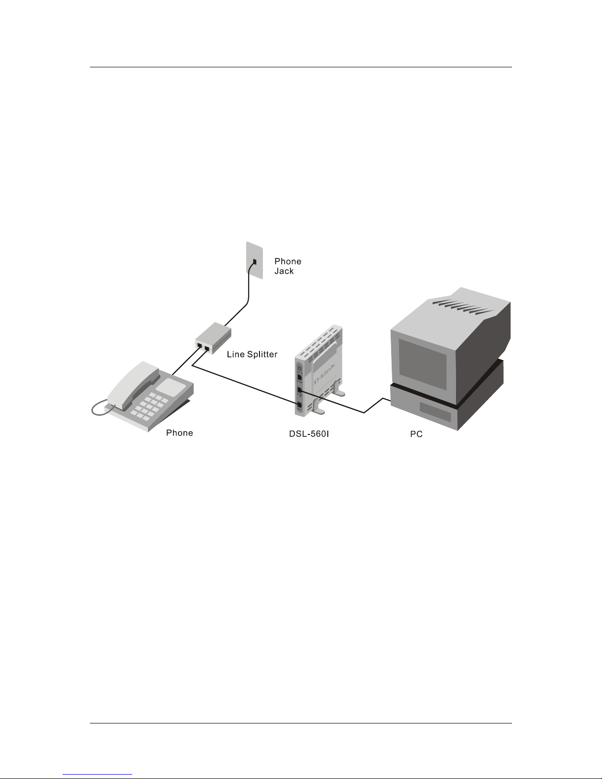
DSL-560I ADSL Router User’s Guide
Line Splitter
If you are instructed to use a “line splitter”, you must install the device between the Modem and the phone jack.
Use standard telephone cable with standard RJ-11 connectors. The splitter has three RJ-11 ports used to connect
to the wall jack, the Modem and if desired, a telephone or telephone device. The connection ports are typically
labeled as follows:
Line - This port connects to the wall jack.
ADSL – This port connects to the Modem.
Phone – This port connects to a telephone or other telephone device.
The diagram below illustrates the proper use of the splitter.
Line Splitter Installation
60
Page 71

Offices
Australia D-Link Australasia
Unit 16, 390 Eastern Valley Way, Roseville, NSW 2069 Australia
TEL: 61-2-9417-7100 FAX: 61-2-9417-1077 TOLL FREE (Australia): 1800-177100
TOLL FREE (New Zealand): 0800-900900
URL: www.dlink.com.au E-MAIL: [email protected] & [email protected]
Level 1, 434 St. Kilda Road, Melbourne, Victoria 3004 Australia
TEL: 61-3-9281-3232 FAX: 61-3-9281-3229 MOBILE: 0412-660-064
Canada D-Link Canada
2180 Winston Park Drive, Oakville, Ontario, L6H 5W1 Canada
TEL: 1-905-829-5033 FAX: 1-905-829-5095 BBS: 1-965-279-8732
TOLL FREE: 1-800-354-6522 URL: www.dlink.ca
FTP: ftp.dlinknet.com E-MAIL: [email protected]
Chile D-Link South America
Isidora Goyeechea 2934 of 702, Las Condes, Santiago, Chile, S. A.
TEL: 56-2-232-3185 FAX: 56-2-232-0923 URL: www.dlink.cl
E-MAIL: [email protected] & [email protected]
China D-Link China
2F, Sigma Building, 49 Zhichun Road, Haidan District, 100080 Beijing, China
TEL: 86-10-88097777 FAX: 86-10-88096789 URL: www.dlink.com.cn
E-MAIL: [email protected]
Denmark D-Link Denmark
Naverland 2, DK-2600 Glostrup, Copenhagen, Denmark
TEL: 45-43-969040 FAX:45-43-424347 URL: www.dlink.dk E-MAIL: [email protected]
Egypt D-Link Middle East
7 Assem Ebn Sabet Street, Heliopolis, Cairo, Egypt
TEL: 20-2-635-6176 FAX: 20-2-635-6192 URL: www.dlink-me.com
E-MAIL: [email protected] & [email protected]
Finland D-Link Finland
Thlli-ja Pakkahuone Katajanokanlaituri 5, FIN– 00160 Helsinki
TEL: 358-9-622-91660 FAX: 358-9-622-91661 URL: www.dlink-fi.com
France D-Link France
Le Florilege #2, Allee de la Fresnerie, 78330 Fontenay le Fleury, France
TEL: 33-1-3023-8688 FAX: 33-1-3023-8689 URL: www.dlink-france.fr
E-MAIL: [email protected]
Germany D-Link Central Europe/D-Link Deutschland GmbH
Schwalbacher Strasse 74, D-65760 Eschborn, Germany
TEL: 49-6196-77990 FAX: 49-6196-7799300 URL: www.dlink.de
BBS: 49-(0) 6192-971199 (analog) BBS: 49-(0) 6192-971198 (ISDN)
INFO: 00800-7250-0000 (toll free) HELP: 00800-7250-4000 (toll free)
REPAIR: 00800-7250-8000 E-MAIL: [email protected]
India D-Link India
Plot No.5, Kurla-Bandra Complex Rd., Off Cst Rd., Santacruz (E), Bombay, 400 098 India
TEL: 91-22-652-6696 FAX: 91-22-652-8914 URL: www.dlink-india.com
E-MAIL: [email protected]
Italy D-Link Mediterraneo Srl/D-Link Italia
Via Nino Bonnet n. 6/b, 20154, Milano, Italy
TEL: 39-02-2900-0676 FAX: 39-02-2900-1723 URL: www.dlink.it E-MAIL: [email protected]
Japan D-Link Japan
10F, 8-8-15 Nishi-Gotanda, Shinagawa-ku, Tokyo 141, Japan
TEL: 81-3-5434-9678 FAX: 81-3-5434-9868 URL: www.d-link.co.jp
E-MAIL: [email protected]
Netherlands D-Link Benelux
Fellenoord 1305611 ZB, Eindhoven, the Netherlands
TEL: 31-40-2668713 FAX: 31-40-2668666 URL: www.d-link-benelux.nl
Page 72

Norway D-Link Norway
Waldemar Thranesgt. 77, 0175 Oslo, Norway
TEL: 47-22-991890 FAX: 47-22-207039
Russia D-Link Russia
Michurinski Prospekt 49, 117607 Moscow, Russia
TEL: 7-095-737-3389 & 7-095-737-3492 FAX: 7-095-737-3390 URL: www.dlink.ru
E-MAIL: [email protected]
Singapore D-Link International
1 International Business Park, #03-12 The Synergy, Singapore 609917
TEL: 65-774-6233 FAX: 65-774-6322 E-MAIL: [email protected]
URL: www.dlink-intl.com
South Africa D-Link South Africa
102 – 106 Witchhazel Avenue, Einstein Park 2, Block B, Highveld Technopark,
Centurion, South Africa
TEL: 27 (0) 12-665-2165 FAX: 27 (0) 12-665-2186 URL: www.d-link.co.za
E-MAIL: [email protected]
Spain D-Link Iberia
C/Sabino De Arana, 56 Bajos, 08028 Barcelona, Spain
TEL: 34 93 4090770 FAX: 34 93 4910795 URL: www.dlinkiberia.es
E-MAIL: [email protected]
Sweden D-Link Sweden
P. O. Box 15036, S-167 15 Bromma, Sweden
TEL: 46-(0) 8-564-61900 FAX: 46-(0) 8-564-61901 E-MAIL: [email protected]
URL: www.dlink.se
Taiwan D-Link Taiwan
2F, No. 119 Pao-Chung Rd, Hsin-Tien, Taipei, Taiwan
TEL: 886-2-2910-2626 FAX: 886-2-2910-1515 URL: www.dlinktw.com.tw
E-MAIL: [email protected]
Turkey D-Link Middle East
Deniz Bilgisayar, Buyukdere Cad. Naci Kasim Sk., No. 5 Mecidiyekoy, Istanbul, Turkey
TEL: 90-212-213-3400 FAX: 90-212-213-3420 E-MAIL: [email protected]
U.A.E. D-Link Middle East
CHS Aptec (Dubai), P.O. Box 33550 Dubai U.A.E.
TEL: 971-4-366-885 FAX: 971-4-355-941 E-MAIL: [email protected]
U.K. D-Link Europe
4
th
Floor, Merit House, Edgware Road, Colindale, London NW9 5AB United Kingdom
TEL: 44 (0) 20-8731-5555 FAX: 44 (0) 20-8731-5511 BBS: 44 (0) 181-235-5511
URL: www.dlink.co.uk E-MAIL: [email protected]
U.S.A. D-Link U.S.A.
53 Discovery Drive, Irvine, CA 92618, USA
TEL: 1-949-788-0805 FAX: 1-949-753-7033 BBS: 1-949-455-1779 & 1-949-455-9616
INFO: 1-800-326-1688 URL: www.dlink.com
E-MAIL: [email protected] & [email protected]
Page 73

Registration Card
Print, type or use block letters.
Your name: Mr./Ms_______________________________________________________________________ ___
Organization: ____________________________________________Dept._________________________ _____
Your title at organization:_____________________________________________________________________
Telephone:_________________________________________ Fax:___________________________________
Organization's full address:__________________________ ______ __ ____ ___ _____ ___ _ ______ __ ____ ___ __
_________________________________________________________________________________________
Country:__________________________________________________________________________________
Date of purchase (Month/Day/Year):_______________________________________
Product
Model
Product Serial No. * Product installed in type of
computer (e.g., Compaq 486)
* Product installed in computer serial No.
(* Applies to adapters only)
Product was purchased from:
Reseller's name:____________________________________________________________________________
Telephone:_________________________________________ Fax:___________________________________
Reseller's full address:_______________________________________________________________________
_________________________________________________________________________________________
Answers to the following questions help us to support your product:
1. Where and how will the product primarily be used?
Home Office Travel Company Business Home Business Personal Use
2. How many employees work at installation site?
1 empl oyee 2-9 10-49 50-99 100-499 500-999 1000 or mor e
3. What network protocol(s) does your organization use ?
XNS/IPX TCP/IP DECnet Others_______________________________________________________
4. What network operating system(s) does your organization use ?
D-Link LA Nsmart Novell NetWare NetWare Lite SCO Unix/Xenix PC NFS 3Com 3+Open
Banyan Vines DECnet Pathwork Windows NT Windows NTAS Windows '95
Others________________________________________________________________________________
5. What network management program does your organization use ?
D-View HP OpenView/Windows HP OpenView/Unix SunNet Manager Novell NMS
NetView 6000 Others___________________________________________________________________
6. What network medium/media does your organization use ?
Fiber-optics Thick coax Ethernet Thin coax Ethernet 10BASE-T UTP/STP
100BASE-TX 100BASE-T4 100VGAnyLAN Others_________________________________________
7. What applications are used on your network?
Desktop publishing Spreadsheet Word processing CAD/CAM
Databas e management Accounting Others_________________________________________________
8. What category best describes your company?
Aerospace Engineering Education Finance Hospital Legal Insurance/Real Estate Manufacturing
Retail/Chainstore/Wholesale Government Transportation/Utilities/Communication VAR
S ystem house/company Other____________________________________________________________
9. Would you recommend your D-Link product to a friend?
Yes No Don't know yet
10.Your comments on this product? ___________________________ ______________________
__________________________________________________________________________________________
__________________________________________________________________________________________
__________________________________________________________________________________________
Page 74
 Loading...