

Page 1
Page 2

Table of Contents
2 D-Link DSL-526E User Manual
Table of
Contents
Table of Contents................................................................................2
Product Overview................................................................................ 4
Package Contents........................................................................... 4
System Requirements..................................................................... 4
Features.......................................................................................... 5
Hardware Overview: Connections................................................... 6
Hardware Overview: LEDs..............................................................7
Installation ...........................................................................................8
Before You Begin............................................................................8
Installation Notes ............................................................................ 8
Information you will need from your ADSL service provider.......... 10
Username............................................................................... 10
Password................................................................................10
WAN Setting / Connection Type.............................................10
Modulation Type.....................................................................10
Security Protocol..................................................................... 10
VPI..........................................................................................10
VCI.......................................................................................... 10
Information you will need about your DSL-526E Modem Router .. 11
Username............................................................................... 11
Password................................................................................ 11
LAN IP addresses for the DSL-526E...................................... 11
LAN Subnet Mask for the DSL-526E...................................... 11
Information you will need about your LAN or computer................. 11
Ethernet NIC........................................................................... 11
DHCP Client status................................................................. 11
Installing the USB Driver...............................................................12
Device Installation.........................................................................16
Power on Router.....................................................................16
Factory Reset Button.............................................................. 16
Network Connections.............................................................. 17
Configuration.....................................................................................18
Web-based Configuration Utility....................................................18
Setup............................................................................................. 20
Wizard.....................................................................................20
Local Network.........................................................................25
LAN Interface....................................................................27
LAN IPv6 Interface............................................................28
DHCP Server....................................................................29
DHCP Reserved...............................................................32
Internet Setup .........................................................................33
Channel Configuration......................................................33
ATM Settings....................................................................36
ADSL Settings ..................................................................37
PVC Auto Search..............................................................38
Time and Date ........................................................................39
Advanced ......................................................................................40
Access Control List .................................................................40
Access Control List...........................................................41
Access Control List IPv6...................................................43
Port Triggering ........................................................................43
Port Forwarding ......................................................................44
DMZ........................................................................................45
Parent Control.........................................................................46
URL Block.........................................................................46
MAC Block........................................................................47
Schedules.........................................................................48
Filtering Options......................................................................49
IP/Port Filter......................................................................49
IPv6/Port Filter..................................................................50
MAC Filter.........................................................................51
DoS Settings...........................................................................52
Page 3

Table of Contents
D-Link DSL-526E User Manual 3
DNS........................................................................................ 53
DNS..................................................................................53
IPv6 DNS.......................................................................... 54
Dynamic DNS......................................................................... 54
Network Tools.........................................................................55
Port Mapping.................................................................... 55
IGMP Proxy...................................................................... 56
IP QoS..............................................................................57
UPnP................................................................................ 58
SNMP............................................................................... 59
TR-069 ............................................................................. 59
Software Forbidden..........................................................61
ARP Binding..................................................................... 61
Client Limit........................................................................ 62
Telnet ...............................................................................62
Routing ...................................................................................63
Static Route......................................................................63
IPv6 Static Route.............................................................. 64
RIP ...................................................................................65
NAT ........................................................................................ 66
NAT ALG.......................................................................... 66
NAT Exclude IP................................................................ 66
NAT Forwarding ...............................................................67
FTP ALG Config............................................................... 67
NAT IP Mapping............................................................... 68
Maintenance..................................................................................69
System....................................................................................69
Firmware Update ....................................................................70
Password................................................................................70
Diagnostics .............................................................................71
Ping ..................................................................................71
Ping6.................................................................................71
Traceroute ........................................................................72
ADSL ................................................................................73
Diag Test ..........................................................................73
System Log.............................................................................74
Logout.....................................................................................74
Status............................................................................................75
Device Information..................................................................75
DHCP Clients..........................................................................76
ADSL Driver............................................................................77
Statistics..................................................................................78
Route Information....................................................................78
Traffic Graphic ........................................................................79
Help............................................................................................... 80
Troubleshooting................................................................................81
Networking Basics ............................................................................83
Check Your IP Address.................................................................83
Statically Assigning an IP Address................................................84
Technical Specifications...................................................................85
Page 4
Product Overview
Product
Overview
Package Contents
DSL-526E Modem Router
Power Adapter
CD-ROM with User Manual
One twisted-pair telephone cable used for ADSL connection
One straight-through Ethernet cable
One USB cable
One Quick Installation Guide
Note: Using a power supply with a different voltage rating other than the one included
with the DSL-526E may cause damage and void the warranty for this product.
System Requirements
ADSL Internet service
Computer with:
200MHz Processor or higher
64MB Memory
CD-ROM Drive
Ethernet Adapter with TCP/IP Protocol Installed
Internet Explorer v6 or later, FireFox v1.5
Computer with Windows 2000, Windows XP, Windows Vista or Windows 7
D-Link Click'n Connect Utility
11
4 D-Link DSL-526E User Manual
Page 5

Product Overview
D-Link DSL-526E User Manual 5
Features
PPP (Point-to-Point Protocol) Security – The Router supports PAP (Password Authentication Protocol) and CHAP (Challenge Handshake
Authentication Protocol) for PPP connections. The Router also supports MSCHAP.
DHCP Support – Dynamic Host Configuration Protocol automatically and dynamically assigns all LAN IP settings to each host on your
network. This eliminates the need to reconfigure every host whenever changes in the network topology occur.
Network Address Translation (NAT) – For small office environments, the Router allows multiple users on the LAN to access the Internet
concurrently through a single Internet account. This provides Internet access to everyone in the office for the price of a single user. NAT
improves network security in effect by hiding the private network behind one global and visible IP address. NA T address mapping can also be
used to link two IP domains via a LAN-to-LAN connection.
TCP/IP (Transmission Control Protocol/Internet Protocol) – The Router supports the TCP/IP protocol, the language used for the Internet.
It is compatible with access servers manufactured by major vendors.
RIP-1/RIP-2 – The Router supports both RIP-1 and RIP-2 exchanges with other routers. Using both versions allows the Router to
communicate with all RIP enabled devices.
Static Routing – This allows you to select a data path to a particular network destination that will remain in the routing table and
never “age out”. Create a static route if you wish to define a specific route that will always be used for data traffic from your LAN to
a specific destination
within your LAN (for example to another router or a server) or to a specific destination outside your network (to an ISP defined default
gateway for instance).
Default Routing – This allows you to choose a default path for incoming data packets for which the destination address is unknown. This is
particularly useful when/if the Router functions as the sole connection to the Internet.
ATM (Asynchronous Transfer Mode) – The Router supports Bridged Ethernet over ATM (RFC1483), IP over ATM (RFC1577), and PPP
over A TM (RFC 2364).
Precise ATM Traffic Shaping – Traffic shaping is a method of controlling the flow rate of ATM data cells. This function helps to establish the
Quality of Service for ATM data transfer.
G.hs (Auto-handshake) – This allows the Router to automatically choose either the G.lite or G.dmt ADSL connection standards.
High Performance – Very high rates of data transfer are possible with the Router. Up to 8 Mbps downstream bit rate using the G.dmt
standard.
Telnet Connection – Telnet enables a network manager to access the Router’s management software remotely.
Easy Installation – The Router uses a web-based graphical user interface program for convenient management access and easy set up.
Any common web browser software can be used to manage the Router.
Page 6
Product Overview
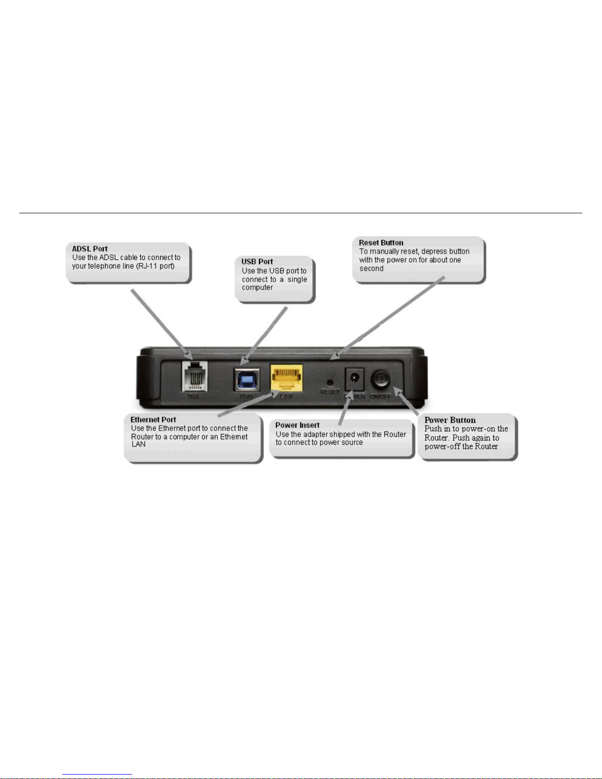
Hardware Overview: Connections
6 D-Link DSL-526E User Manual
Page 7
Product Overview
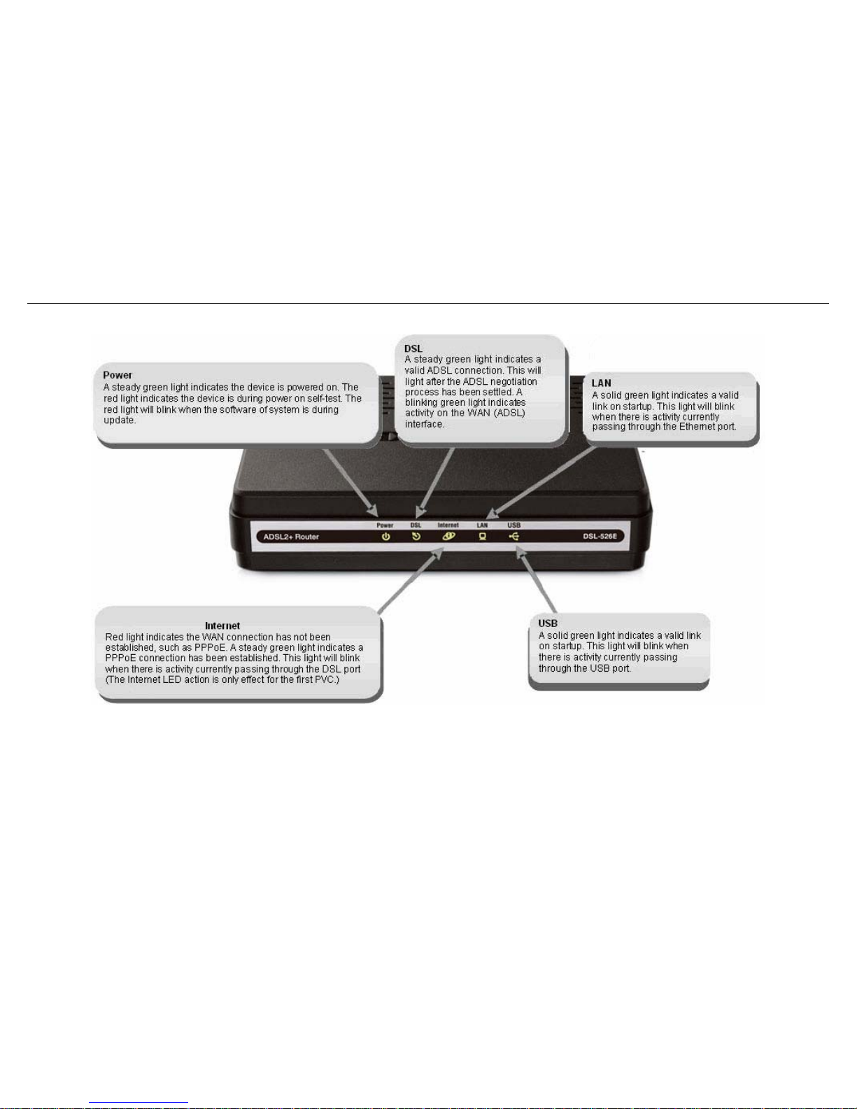
Hardware Overview: LEDs
D-Link DSL-526E User Manual 7
Page 8

Installation
8 6E User Manual D-Link DSL-52
Any common web browser can be used to configure the Router using the web configuration management software. The program is designed to
work best with more recently released browsers such as Opera, Microsoft Internet Explorer® version 6.0, Netscape Navigator® version 6.2.3, or
later versions. The web browser must have JavaScript enabled. JavaScript is enabled by default on many browsers. Make sure JavaScript has not
been disabled by other software (such as virus protection or web user security packages) that may be running on your computer.
Installation
This section will walk you through the installation process. Placement of the Router is very important. Do not place the Router in an enclosed area
such as a closet, cabinet or in the attic or garage.
Before You Begin
Please read and make sure you understand all the prerequisites for proper installation of your new Router. Have all the necessary information and
equipment on hand before beginning the installation.
Installation Notes
In order to establish a connection to the Internet, it will be necessary to provide information to the Router that will be stored in its memory. For
some users, only their account information (Username and Password) is required. For others, various parameters that control and define the
Internet connection will be required. You can print out the two pages below and use the tables to list this information. This way you have a hard
copy of all the information needed to setup the Router. If it is necessary to reconfigure the device, all the necessary information can be easily
accessed. Be sure to keep this information safe and private.
Low Pass Filters
Since ADSL and telephone services share the same copper wiring to carry their respective signals, a filtering mechanism may be necessary to
avoid mutual interference. A low pass filter device can be installed for each telephone that shares the line with the ADSL line. These filters are easy
to install passive devices that connect to the ADSL device and/or telephone using a standard telephone cable. Ask your service provider for more
information about the use of low pass filters with your installation.
Operating Systems
The DSL-526E uses an HTML-based web interface for setup and management. The web configuration manager may be accessed using any
operating system capable of running web browser software, including Windows 98 SE, Windows ME, Windows 2000, Windows XP, and Windows
Vista.
Web Browser
Page 9
Installation
USB Port or Ethernet Port (NIC Adapter)
Any computer that uses the Router must be able to connect to it through either the Ethernet port or USB port on the Router. The easiest method of
installation is via the Ethernet connection, which requires your computer be equipped with an Ethernet port. Most notebook computers are now sold
with an Ethernet port already installed. Likewise, most fully assembled desktop computers come with an Ethernet NIC adapter as standard. If your
computer does not have an Ethernet port and you do not wish to use a USB connection, you must install an Ethernet NIC adapter before you can use
the Router. If you need to install an adapter, follow the installation instructions that come with the Ethernet NIC adapter.
Additional Software
It may be necessary to install software on your computer that enables the computer to access the Internet. Additional software must be installed if
you are using the device as a simple bridge. For a bridged connection, the information needed to make and maintain the Internet connection is
stored on another computer or gateway device, not in the Router itself.
If your ADSL service is delivered through a PPPoE or PPPoA connection, the information needed to establish and maintain the Internet connection
can be stored in the Router. In this case, it is not necessary to install software on your computer. It may however be necessary to change some
settings in the device, including account information used to identify and verify the connection.
All connections to the Internet require a unique global IP address. For bridged connections, the global IP settings must reside in a TCP/IP enabled
device on the LAN side of the bridge, such as a PC, a server, a gateway device, such as a router, or similar firewall hardware. The IP address can be
assigned in a number of ways. Your network service provider will give you instructions about any additional connection software or NIC configuration
that may be required.
If you plan to use the DSL-526E’s USB port to connect to your
computer, do not connect the USB cable to the Router until you
have finished all of the steps to install the USB driver, and your
computer has restarted.
Note
D-Link DSL-526E User Manual 9
Page 10

Installation
10 D-Link DSL-526E User Manual
Information you will need from your ADSL service provider
Username
This is the Username used to log on to your ADSL service provider’s network. Your ADSL service provider uses this to identify your account.
Password
This is the Password used, in conjunction with the Username above, to log on to your ADSL service provider’s network. This is used to verify the
identity of your account.
WAN Setting / Connection Type
These settings describe the method your ADSL service provider uses to transport data between the Internet and your computer. Most users will use
the default settings. Y ou may need to specify one of the following WAN Setting and Connection Type configurations (Connection T ype settings listed
in parenthesis):
PPPoE/PPPoA (PPPoE LLC, PPPoA LLC or PPPoA VC-Mux)
Bridge Mode (1483 Bridged IP LLC or 1483 Bridged IP VC Mux)
IPoA/MER (Static IP Address) (Bridged IP LLC, 1483 Bridged IP VC Mux, 1483 Routed IP LLC, 1483 Routed IP VC-Mux or IPoA)
MER (Dynamic IP Address) (1483 Bridged IP LLC or 1483 Bridged IP VC-Mux)
Modulation Type
ADSL uses various standardized modulation techniques to transmit data over the allotted signal frequencies. Some users may need to change the
type of modulation used for their service. The default DSL modulation (ADSL2+ Multi-Mode) used for the Router automatically detects all types of
ADSL, ADSL2 and ADSL2+ modulation.
Security Protocol
This is the method your ADSL service provider will use to verify your Username and Password when you log on to their network. Your Router
supports the PAP and CHAP protocols.
VPI
Most users will not be required to change this setting. The Virtual Path Identifier (VPI) is used in conjunction with the Virtual Channel Identifier (VCI)
to identify the data path between your ADSL service provider’s network and your computer. If you are setting up the Router for multiple virtual
connections, you will need to configure the VPI and VCI as instructed by your ADSL service provider for the additional connections. This setting can
be changed in the WAN Settings window of the web management interface.
VCI
Most users will not be required to change this setting. The Virtual Channel Identifier (VCI) is used in conjunction with the VPI to identify the data path
between your ADSL service provider’s network and your computer. If you are setting up the Router for multiple virtual connections, you will need to
configure the VPI and VCI as instructed by your ADSL service provider for the additional connections. This setting can be changed in the WAN
Setup window of the web management interface.
Page 11

Installation
D-Link DSL-526E User Manual 11
Information you will need about your DSL-526E Modem Router
Username
This is the Username needed to access the Router’s management interface. When you attempt to connect to the device through a web browser you
will be prompted to enter this Username. The default Username for the Router is “admin”. The user cannot change this.
Password
This is the Password you will be prompted to enter when you access the Router’s management interface. The default Password is “admin.” The
user may change this.
LAN IP addresses for the DSL-526E
This is the IP address you will enter into the Address field of your web browser to access the Router’s configuration graphical user interface (GUI)
using a web browser. The default IP address is 192.168.1.1. This may be changed to suit any IP address scheme the user desires. This address will
be the base IP address used for DHCP service on the LAN when DHCP is enabled.
LAN Subnet Mask for the DSL-526E
This is the subnet mask used by the DSL-526E and will be used throughout your LAN. The default subnet mask is 255.255.255.0. This can be
changed later.
Information you will need about your LAN or computer
Ethernet NIC
If your computer has an Ethernet NIC, you can connect the DSL-526E to the Ethernet port using an Ethernet cable. You can also use the Ethernet
ports on the DSL-526E to connect to other computers or Ethernet devices.
DHCP Client status
Your DSL-526E Modem Router is configured, by default, to be a DHCP server. This means that it can assign an IP address, subnet mask and a
default gateway address to computers on your LAN. The default range of IP addresses the DSL-526E will assign are from 192.168.1.2 to
192.168.1.254. Your computer (or computers) needs to be configured to obtain an IP address automatically (that is, they need to be configured
as DHCP clients.)
It is recommended that you collect and record this information here, or in some other secure place, in case you have to re-configure your ADSL
connection in the future.
Once you have the above information, you are ready to setup and configure your DSL-526E Modem Router.
Page 12
Installation
Installing the USB Driver
The CD-ROM shipped with the Router contains the USB driver software. Insert the DSL-526E CD-ROM into the CD drive. Within a few seconds you
should see a window that offers the following options: View Manual, View QIG, Install Acrobat Reader, Technical Support, Quick Installation and Exit.
If you do not see this auto-run pop-up window, explore the CD-ROM and double-click the file Setup.exe to launch the installation software. The autorun USB driver setup must be completed before connecting the router to your PC with the USB cable.
To install the driver under a Windows XP system, follow these instructions:
Method 1
1. Connect one end of the USB cable to the USB port of the Router
and the other end to the USB port of your PC.
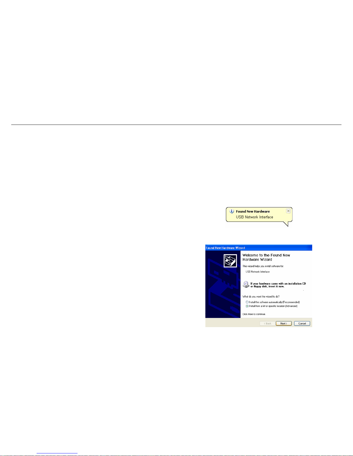
2. When the PC powers up, a message appears in the system tray
indicating that new hardware is found.
3. The Found New Hardware Wizard dialog box appears. Select
Install from a list or specific location (Advanced). Click Next to
continue.
12 D-Link DSL-526E User Manual
Page 13
Installation
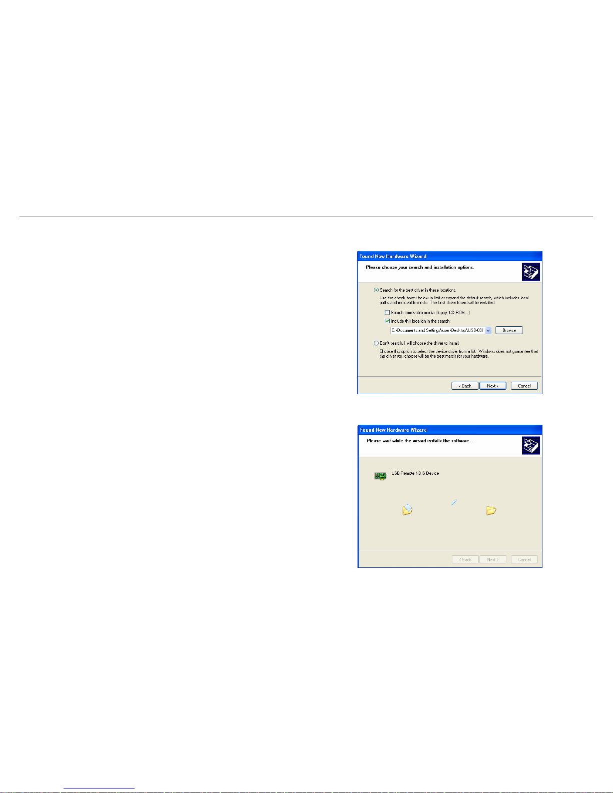
4. The dialog instructs you to choose your search and installation
options. You can choose the path of USB drive installation. Click
Next.
5. A dialog box appears, saying Please wait while the wizard
installs the software. Then click Next.
D-Link DSL-526E User Manual 13
Page 14
Installation
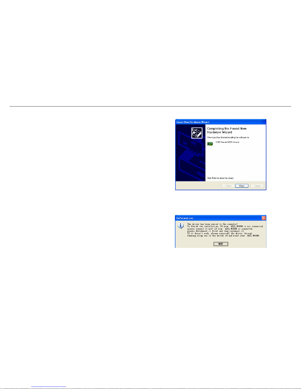
6. Click Finish to complete the USB driver installation.
Method 2
1. Connect the USB cable to the PC, and then run Setup.exe on the
PC. Follow the screen instruction to go through the installation, and
then the right dialogue box will be prompted.
2. When the above dialogue box is prompted:
z If your router is not connected, please connect it now;
z If the router is connected, please disconnect and then reconnect it.
After connection, the USB drive will be installed automatically
installed in your PC. Then click OK in the above dialogue box to
14 D-Link DSL-526E User Manual
Page 15
Installation
finish the installation. To view the device, go to Computer
Management (Local) > Device Manager, click ,
and you will see the icon . If it does not work,
please rerun Setup.exe and then reset the router.
Note: Do not run Setup.exe on the PC when the USB cable is
disconnected to the PC.
When the USB driver has been installed, carry out the following steps:
1. Insert one end of the USB cable included with the Router into the DSL-526E Router’s USB port.
2. Insert the other end of the USB cable into a spare USB port on your PC.
3. Connect the power adapter to the power input in the back panel of the DSL-526E and then plug the other end of the power adapter to a wall
outlet or power strip.
4. Press the power button to switch on the Router. On the front of the device, the Power LED will turn ON to indicate proper operation.
5. Insert the telephone cable included with the Router into the ADSL port, and then connect the cable to your telephone line.
6. Check the DSL LED on the front of the Router to confirm that the connections have been made.
D-Link DSL-526E User Manual 15
Page 16

Installation
16 D-Link DSL-526E User Manual
Device Installation
The DSL-526E has three separate physical interfaces, an ADSL (WAN), an Ethernet (LAN) interface and a USB Interface. The Router can be
connected to your PC via the USB port or the Ethernet port. Place the Router in a location where it can be connected to the various devices as well
as to a power source. The Router should not be located where it will be exposed to moisture or excessive heat. Make sure the cables and power
cord are placed safely out of the way so they do not create a tripping hazard. As with any electrical appliance, observe common sense safety
procedures.
The Router can be placed on a shelf or desktop, ideally you should be able to see the LED indicators on the front if you need to view them for
troubleshooting.
Power on Router
The Router must be used with the power adapter included with the device.
1. Insert the AC Power Adapter cord into the power receptacle located on the rear panel of the Router and plug the adapter into a suitable nearby
power source.
2. Depress the Power button into the on position. You should see the Power LED indicator light up and remain lit. The Status LED should light solid
green and begin to blink after a few seconds.
3. If the Ethernet port is connected to a working device, check the Ethernet LAN LED indicator to make sure the connection is valid. The Router
will attempt to establish the ADSL connection, if the ADSL line is connected and the Router is properly configured this should light up after
several seconds. If this is the first time you have installed the device, some settings may need to be changed before the Router can
establish a connection.
Factory Reset Button
The Router may be reset to the original factory default settings. To restore factory defaults, keep the device powered on and push a paper clip into
the hole. Press down the button for 3 seconds using a ballpoint or paperclip, and then release.
Remember that this will wipe out any settings stored in flash memory including user account information and LAN IP settings. The device settings
will be restored to the factory default IP address 192.168.1.1 and the subnet mask 255.255.255.0, the default management Username is “admin”
and the default Password is “admin”.
Page 17

Installation
D-Link DSL-526E User Manual 17
Network Connections
Connect ADSL Line
Use the ADSL cable included with the Router to connect it to a telephone wall socket or receptacle. Plug one end of the cable into the ADSL port
(RJ-11 receptacle) on the rear panel of the Router and insert the other end into the RJ-1 1 wall socket. If you are using a low pass filter device, follow
the instructions included with the device or the instructions given to you by your service provider. The ADSL connection represents the WAN
interface, the connection to the Internet. It is the physical link to the service provider’s network backbone and ultimately to the Internet.
Connect Router to Ethernet
The Router may be connected to a single computer or Ethernet device through the 10/100 BASE-TX Ethernet port on the rear panel. Any
connection to an Ethernet concentrating device such as a switch or hub must operate at a speed of 10/100 Mbps only . When connecting the Router
to any Ethernet device that is capable of operating at speeds higher than 10Mbps, be sure that the device has auto-negotiation (NWay) enabled for
the connecting port. Use standard twisted-pair cabling with RJ-45 connectors. The RJ-45 port on the Router is a crossed port (MDI-X). Follow
standard Ethernet guidelines when deciding what type of cable to use to make this connection. When connecting the Router directly to a PC or
server, use a normal straight-through cable. You should use a crossed cable when connecting the Router to a normal (MDI-X) port on a switch or
hub. Use a normal straight-through cable when connecting it to an uplink (MDI-II) port on a hub or switch. The rules governing Ethernet cable
lengths apply to the LAN to Router connection. Be sure that the cable connecting the LAN to the Router does not exceed 100 meters.
Hub or Switch to Router Connection
Connect the Router to an uplink port (MDI-II) on an Ethernet hub or switch with a straight-through cable. If you wish to reserve the uplink port on the
switch or hub for another device, connect to any of the other MDI-X ports (1x, 2x, etc.) with a crossed cable.
Computer to Router Connection
You can either connect the Router’s Ethernet interface directly to a 10/100BASE-TX Ethernet adapter card (NIC) installed in a PC using the
Ethernet cable provided, or connect the Router to a spare USB port using the Router’s USB interface.
Page 18
Configuration
Configuration
This section describes how to configure your new D-Link Router using the web-based configuration utility.
Web-based Configuration Utility
Connect to the Router
To configure the WAN connection used by the Router, it is first necessary to communicate with the Router through its management interface, which
is HTML-based and can be accessed using a web browser. To make sure your computer has the correct IP settings, configure it to use the DHCP
server in the Router. The next section describes how to change the IP configuration for a computer running a Windows operating system to be a
DHCP client.
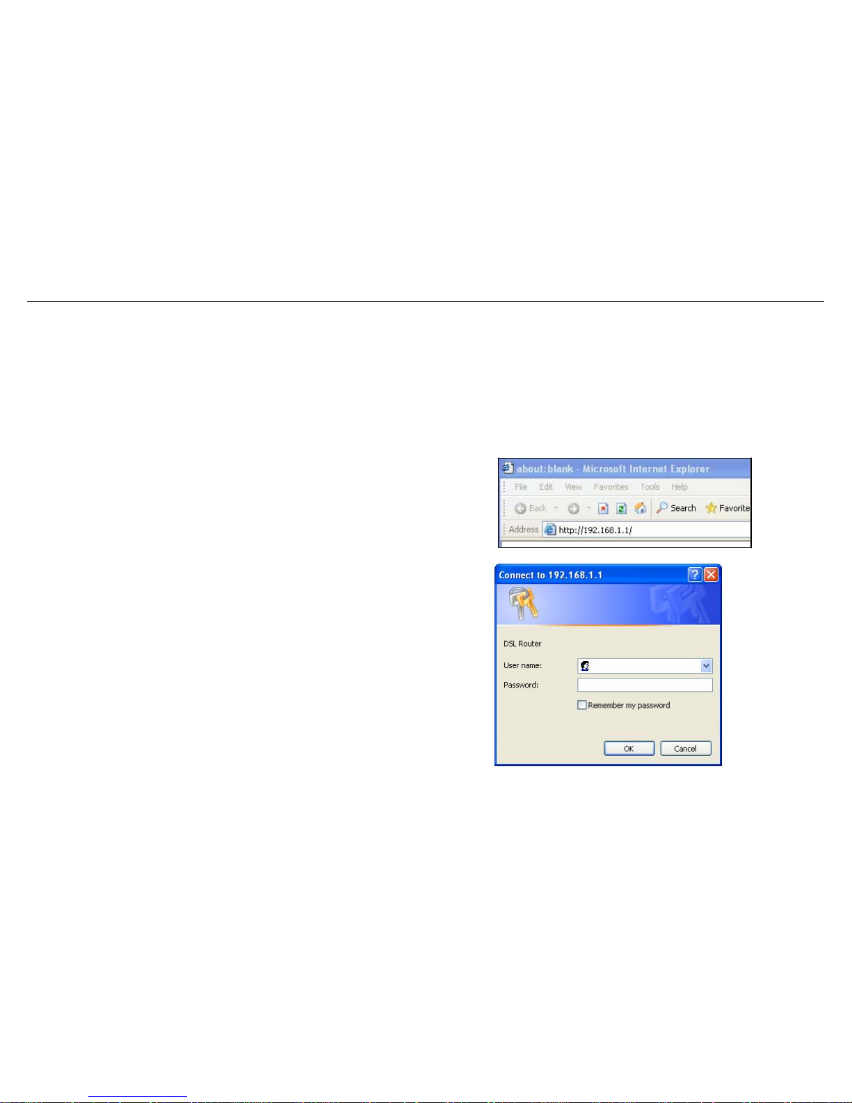
To access the configuration utility, open a web-browser such as Internet
Explorer and enter the IP address of the router (192.168.1.1).
Type “admin” for the User Name and “admin” in the Password field. If
you get a Page Cannot be Displayed error, please refer to the
section of Troubleshooting for assistance.
18 D-Link DSL-526E User Manual
Page 19
Configuration
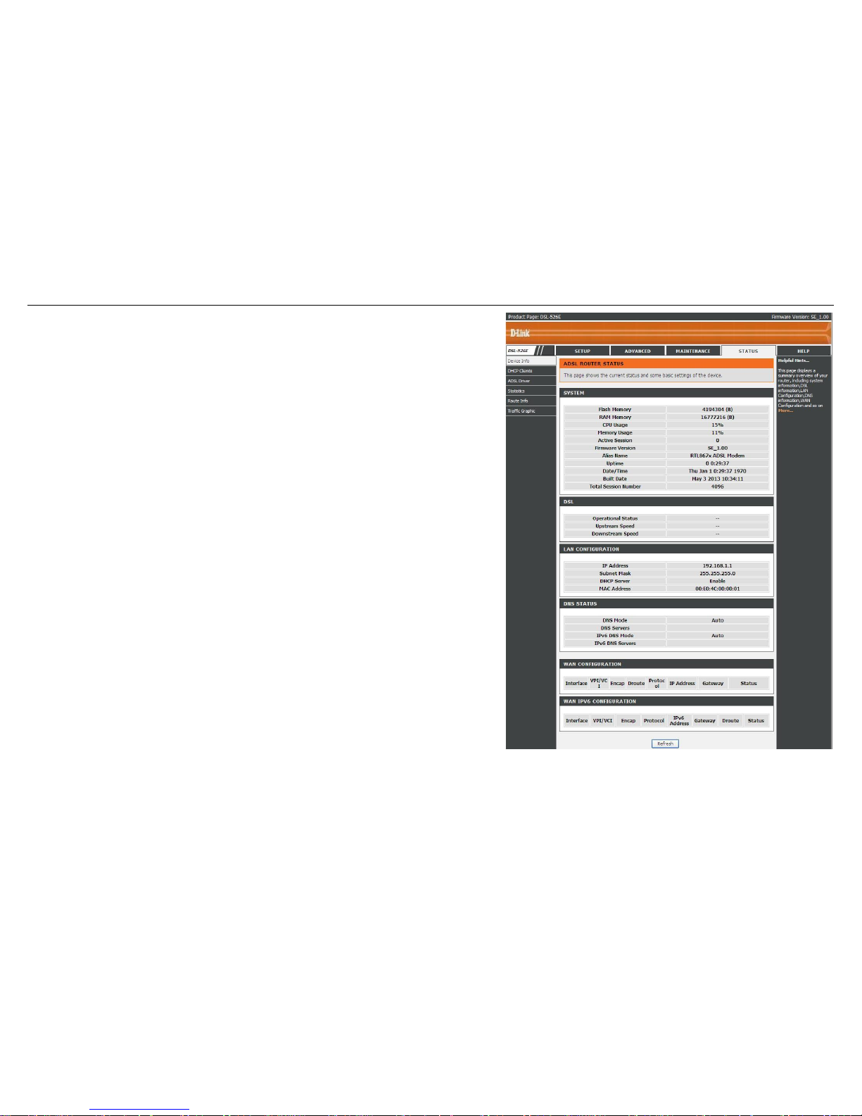
If you log in as the super user successfully, the page shown in the right figure
appears. This page displays a summary overview of the router, including the system
information, DSL information, LAN Configuration, DNS information and WAN
Configuration.
D-Link DSL-526E User Manual 19
Page 20

Configuration
Setup
In the main interface, click Setup tab to enter the Setup menu as shown in the following figure. The submenus are Wizard, Local Network,
Internet Setup and Time and Date.
Wizard
Wizard enables fast and accurate configuration of Internet connection and other important parameters. The following sections describe
configuration parameters.
When subscribing to a broadband service, you should be aware of the method, by which you are connected to the Internet. Your physical WAN
device can be Ethernet, DSL, or both.
Technical information about the properties of your Internet connection is provided by your Internet service provider (ISP). For example, your ISP
should inform you that you are connected to the Internet using a static or dynamic IP address, and the protocol you use to communicate over the
Internet, i.g. PPPoA or PPPoE.
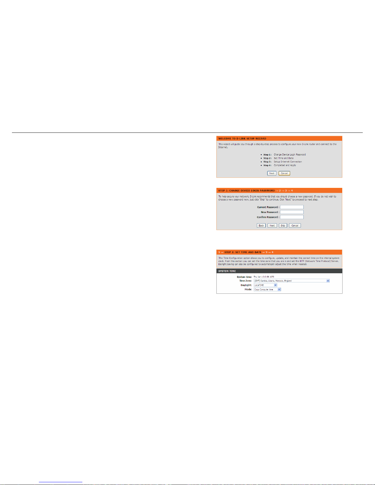
Choose Setup > Wizard. The page shown in the right figure appears.
Click Setup Wizard. The page shown in the following figure appears.
There are 4 steps to configure the device. Click Next to continue.
20 D-Link DSL-526E User Manual
Page 21
Configuration
Step 1 Change the device login password.
Step 2 Set the time and date.
D-Link DSL-526E User Manual 21
Page 22
Configuration
22 D-Link DSL-526E User Manual
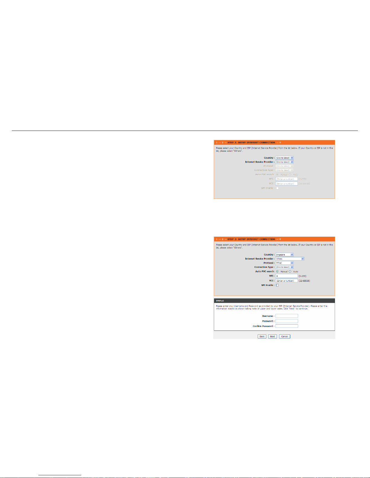
Step 3 Configure the Internet connection.
- PPPoE/ PPPoA
If the internet service you subscribed is PPPoE or PPPoA, you can
choose the Protocol to be PPPoE or PPPoA. Set the VPI and VCI. Enter
the user name and password provided by your ISP.
Page 23
Configuration
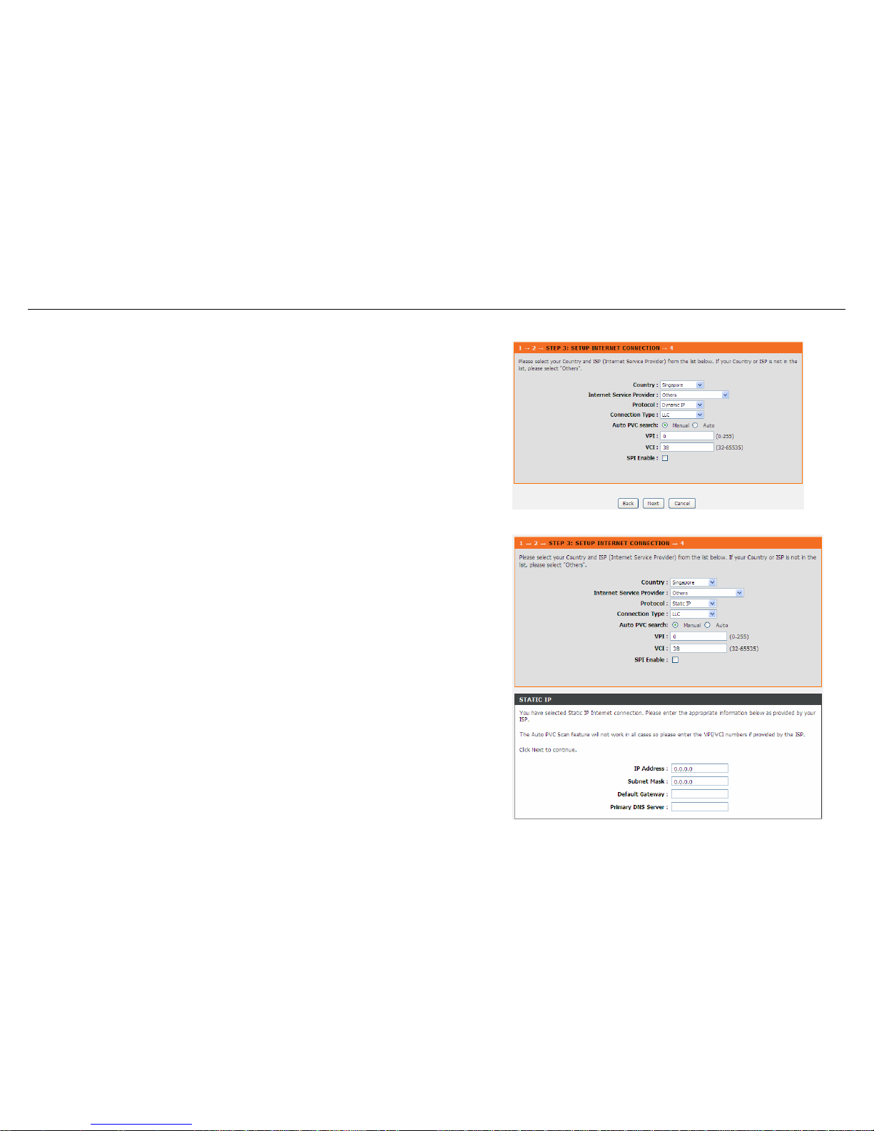
- Dynamic IP
D-Link DSL-526E User Manual 23
If the internet service you subscribed is Dynamic IP, you can choose Protocol to be
Dynamic IP. The page shown in the right figure appears.
- Static IP
If the Protocol is Static IP, you can choose Protocol to be Static IP. The page
shown in the right figure appears. Enter the IP Address, Subnet Mask, Default
Gateway and Primary DNS Server provided by your ISP.
Page 24
Configuration
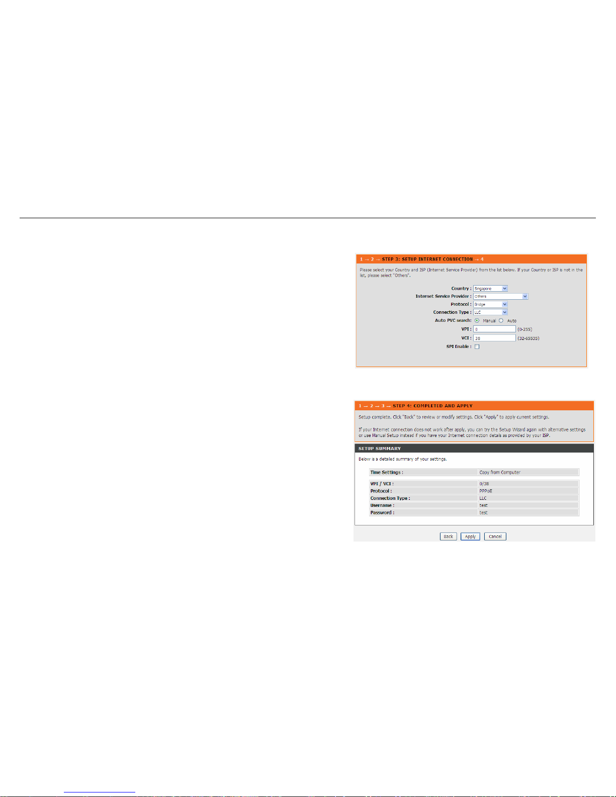
- Bridge
If the Protocol is Bridge, the page shown in the right figure appears.
Step 4 Complete and apply the settings. Click Apply to save the settings.
24 D-Link DSL-526E User Manual
Page 25
Configuration
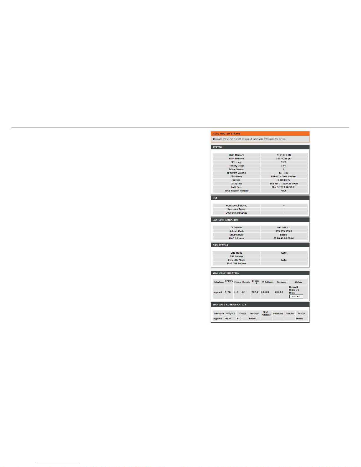
You will go to the ADSL Router Status page as shown in the right figure.
Note: In each step of the Wizard page, you can click Back to review or modify the
previous settings. Click Cancel to exit the wizard page.
Local Network
D-Link DSL-526E User Manual 25
You can configure the LAN IP address according to the actual application. The preset IP address is 192.168.1.1. You can use the default settings
Page 26

Configuration
26 D-Link DSL-526E User Manual
and DHCP service to manage the IP settings for the private network. The IP address of the device is the base address used for DHCP. To use the
device for DHCP on your LAN, the IP address pool used for DHCP must be compatible with the IP address of the device. The IP address available
in the DHCP IP address pool changes automatically if you change the IP address of the device.
You can also enable the secondary LAN IP address. The two LAN IP addresses must be in different networks.
Page 27
Configuration
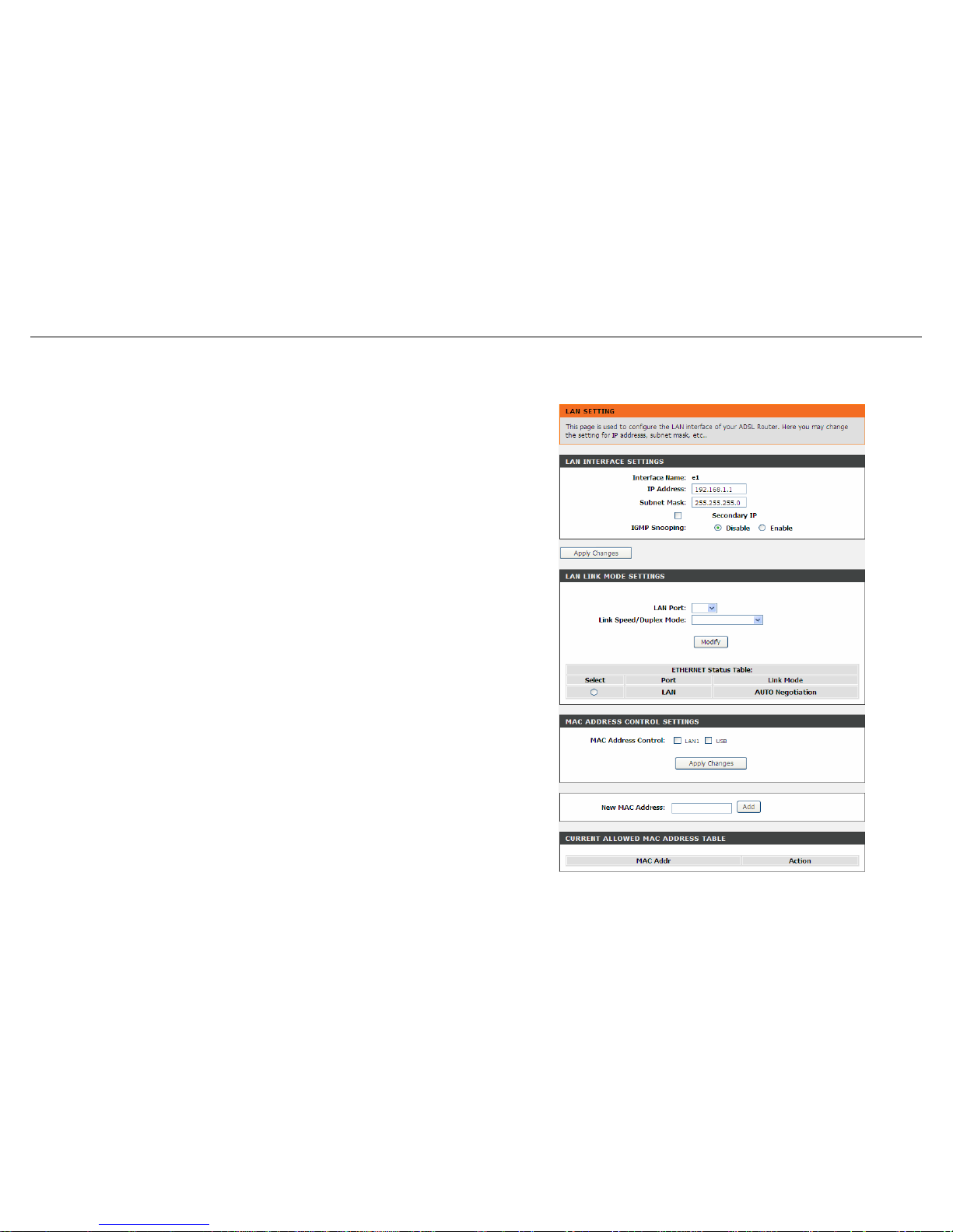
LAN Interface
Choose Setup > Local Network > LAN Interface. The LAN Setting page shown in
the right figure appears. You may configure the LAN interface, for example, the IP
address and subnet mask.
Configure the parameters in this page as described below.
IP Address: Enter the IP address of LAN interface. It is recommended to use an
address from a block reserved for private use. This address block is 192.168.1.1-
192.168.1.254.
Subnet Mask: Enter the subnet mask of LAN interface. The range of subnet mask is
from 255.255.0.0-255.255.255.254.
Secondary IP: Select it to enable the secondary LAN IP address. The two LAN IP
addresses must be in different subnets.
LAN Port: You may choose the LAN interface you want to configure.
Link Speed/ Duplex Mode: You may select one mode from the drop-downlist:
100Mbps/FullDuplex, 100Mbps/Half Duplex, 10Mbps/FullDuplex, 10Mbps/Half
Duplex and Auto Negotiation.
MAC Address Control: It is the access control based on MAC address. Select it, and
the host whose MAC address is listed in the Current Allowed MAC Address Table
can access the modem.
Add: Enter MAC address, and then click this button to add a new MAC address.
D-Link DSL-526E User Manual 27
Page 28
Configuration
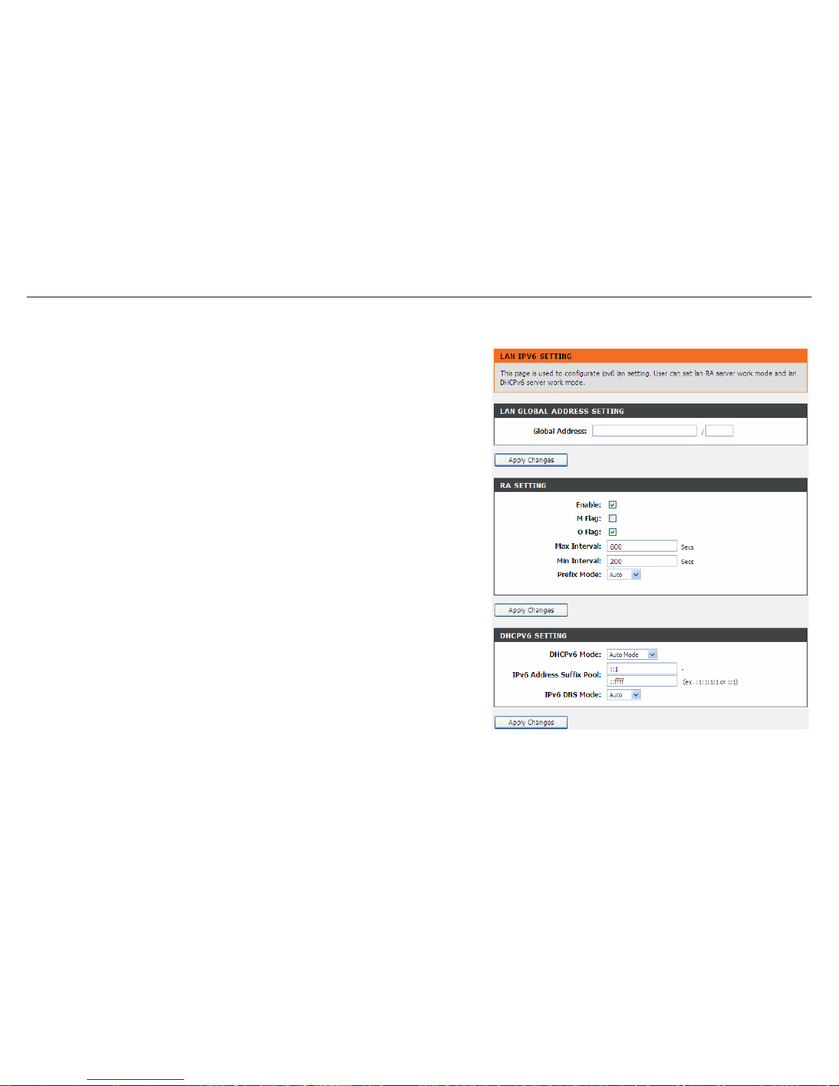
LAN IPv6 Interface
Choose Setup > Local Network > LAN IPv6 Interface. The LAN IPv6 Setting page
shown in the right figure appears. You may set LAN RA server work mode and LAN
DHCPv6 server work mode.
Configure the parameters in this page as described below.
Global Address: Specify the LAN global ipv6 address. It can be assigned by ISP.
Enable: Enable or disable the Router Advertisement feature.
M Flag: Enable or disable the “Managed address configuration” flag in RA packet.
O Flag: Enable or disable the “Other configuration” flag in RA packet.
Prefix Mode: Specify the RA feature prefix mode: “Auto”: the RA prefix will use WAN
dhcp-pd prefix; “Manual”: user will specify the prefix address, length, preferred time
and valid time.
DHCPv6 Mode: Specify the dhcpv6 server mode: “None”: close dhcpv6 server;
“Manual”: dhcpv6 server is opened and user specifies the dhcpv6 server address
pool and other parameters; “Auto”: dhcpv6 server is opened and it use WAN dhcp-pd
prefix to generate address pool.
28 D-Link DSL-526E User Manual
Page 29
Configuration
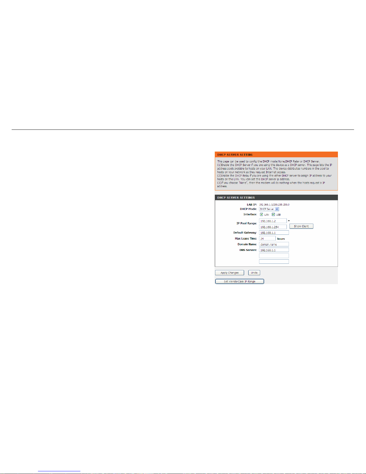
DHCP Server
Choose Setup > Local Network > DHCP Server. The DHCP Server Setting page
shown appears. You may configure the DHCP mode.
Configure the parameters in this page as described below.
DHCP Mode: If set to DHCP Server, the router can assign IP addresses, IP default
gateway and DNS servers to the host in Windows95, Windows NT and other
operation systems that support the DHCP client.
IP Pool Range: It specifies the first and last IP addresses in the IP address pool. The
router assigns IP address in the IP pool range to the host.
Max Lease Time: The lease time determines the period that the host retains the
assigned IP addresses before the IP addresses change.
Domain Name: Enter the domain name if you know. If you leave this blank, the
domain name obtained by DHCP from the ISP is used. You must enter host name
(system name) on each individual PC. The domain name can be assigned from the
router through the DHCP server.
DNS Servers: You can configure the DNS server ip addresses for DNS Relay.
D-Link DSL-526E User Manual 29
Page 30
Configuration
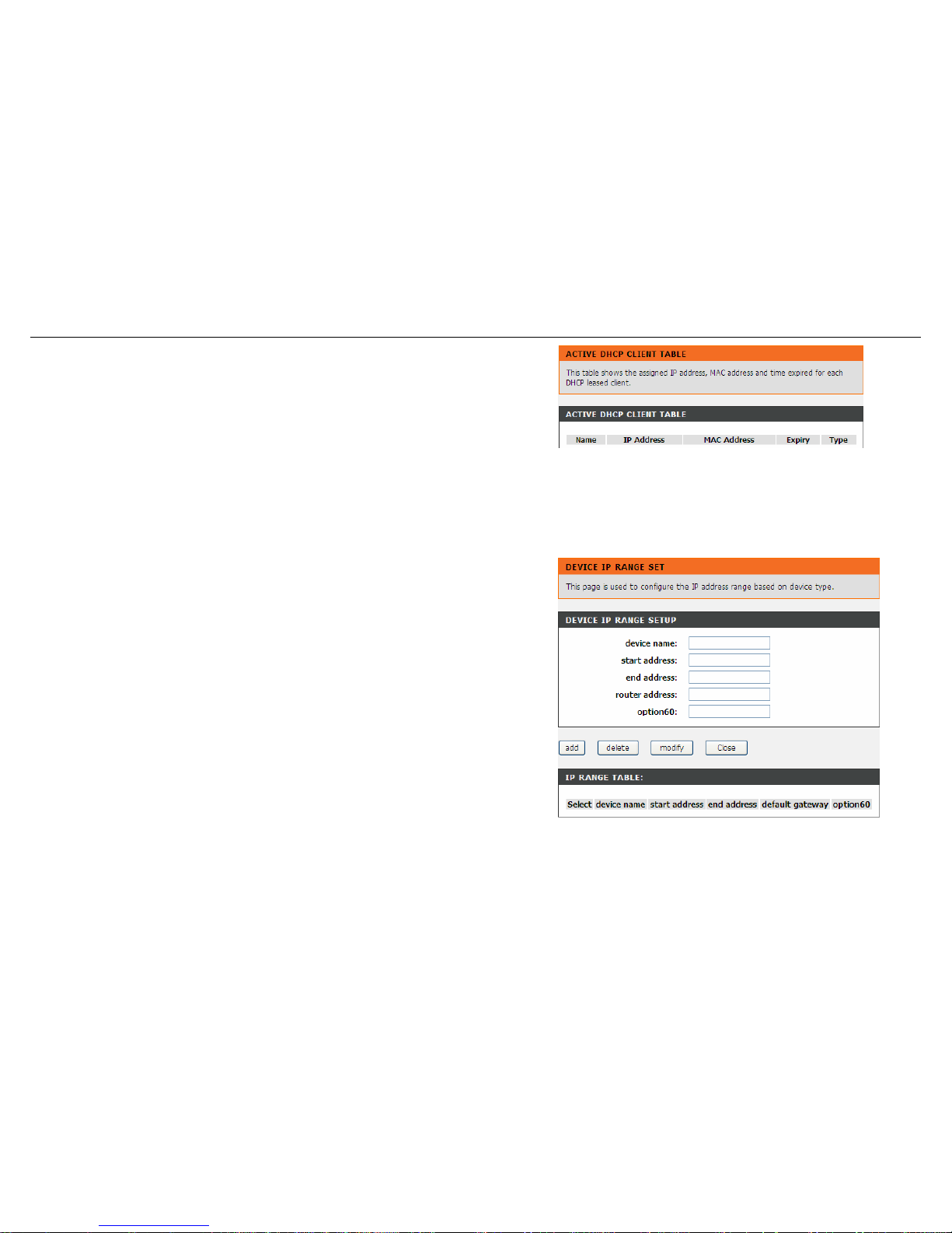
In the DHCP Server Setting page, click the button Show Client to display the page
Active DHCP Client Table. It shows the IP addresses assigned to DHCP clients.
Configure the parameters in this page as described below.
IP Address: It displays the IP address assigned to the DHCP client from the router.
MAC Address: It displays the MAC address of the DHCP client. Each Ethernet
device has a unique MAC address. The MAC address is assigned at the factory and it
consists of six pairs of hexadecimal character, for example, 00-A0-C5-00-02-12.
Expiry: It displays the lease time. The lease time determines the period that the host
retains the assigned IP addresses before the IP addresses change.
Refresh: Click it to refresh this page.
In the DHCP Server Setting page, click the button Set VendorClass IP Range to
display the page Device IP Range Set. In this page, you can configure the IP
address range based on the device type.
30 D-Link DSL-526E User Manual
Page 31
Configuration
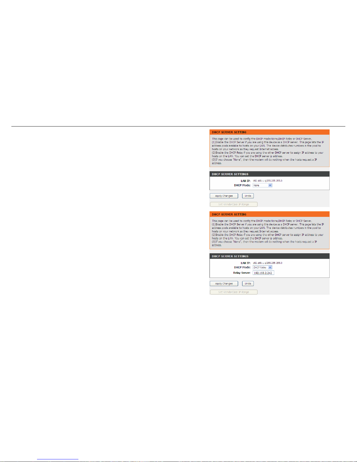
In the DHCP Server Setting page, choose None at the DHCP Mode field, and the
page shown on the left appears.
In the DHCP Server Setting page, choose DHCP Relay at the DHCP Mode field,
and the page shown on the left appears.
Configure the parameters in this page as described below.
DHCP Mode: If set to DHCP Relay, the router acts a surrogate DHCP Server and
relays the DHCP requests and responses between the remote server and the client.
Relay Server: Enter the DHCP server address provided by your ISP.
Apply Changes: Click it to save the settings of this page.
D-Link DSL-526E User Manual 31
Page 32
Configuration
DHCP Reserved
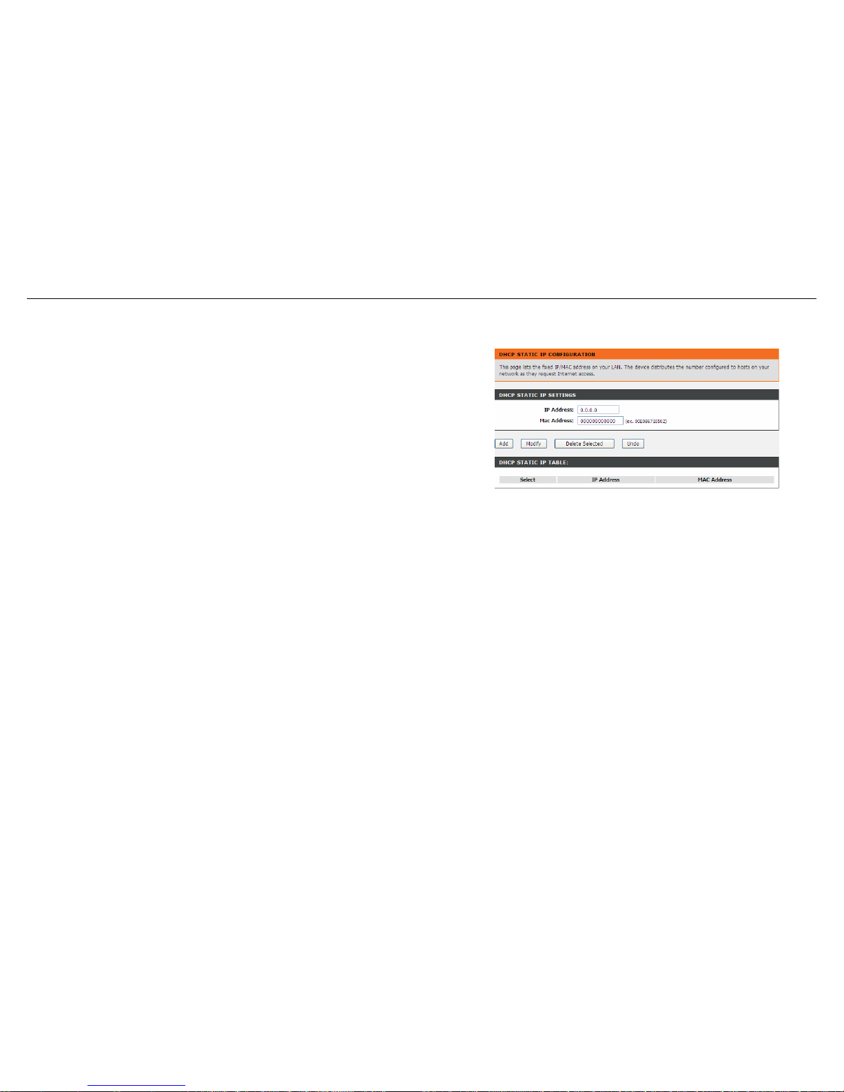
Choose Setup > Local Network > DHCP Reserved. The DHCP Static IP
Configuration page appears. This page lists the fixed IP/MAC address on your LAN.
The device distributes the number configured to hosts on your network as they
request Internet access.
Configure the parameters in this page as described below.
IP Address: Enter the specified IP address in the IP pool range, which is assigned to
the host.
Mac Address: Enter the MAC address of a host on the LAN.
Add: After entering the IP address and MAC address, click this button to add them to
the DHCP Static IP Table.
Delete Selected: Select a row in the DHCP Static IP Table, then click it, this row is
deleted.
Undo: Click it to refresh this page.
DHCP Static IP Table: It shows the assigned IP address based on the MAC address.
32 D-Link DSL-526E User Manual
Page 33
Configuration
Internet Setup
Channel Configuration
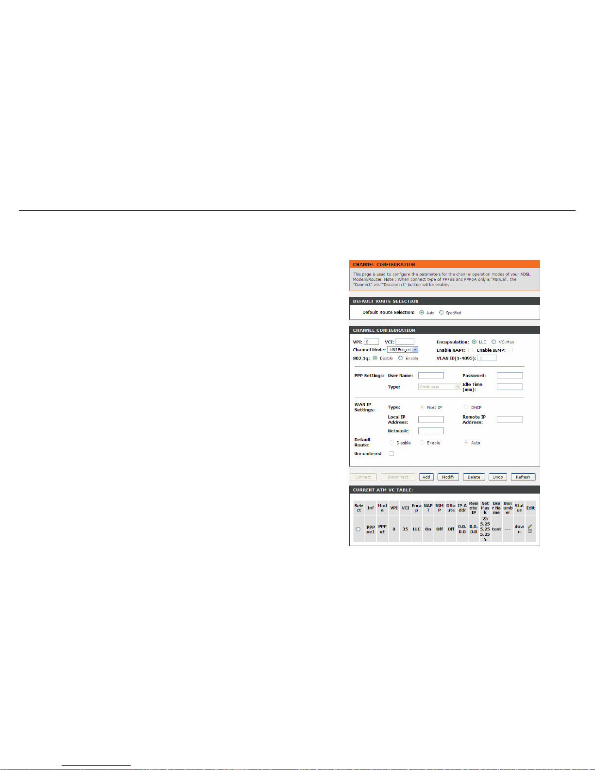
Choose Setup > Internet Setup > Channel Config. The Channel Configuration
page appears. You may configure the parameters for the channel operation modes of
your ADSL Router.
Configure the parameters in this page as described below.
Default Route Selection: You can select Auto or Specified.
VPI: The virtual path between two points in an ATM network, ranging from 0 to 255.
VCI: The virtual channel between two points in an ATM network, ranging from 32 to
65535 (1 to 31 are reserved for known protocols).
Encapsulation: You can choose LLC and VC-Mux.
Channel Mode: You can choose 1483 Bridged, 1483 MER, PPPoE, PPPoA, 1483
Routed or IPoA.
Enable NAPT: Select it to enable Network Address Port Translation (NAPT) function.
If you do not select it and you want to access the Internet normally, you must add a
route on the uplink equipment. Otherwise, the access to the Internet fails. Normally, it
is enabled.
Enable IGMP: You can enable or disable Internet Group Management Protocol
(IGMP) function.
802.1q: You can select Disable or Enable. If enabled, you need to enter the VLAN
ID.
VLAN ID: The value ranges from 1 to 4095.
IP Protocol: When any channel mode except 1483 Bridged is selected, select an IP
protocol from IPv4/IPv6, IPv4 and IPv6.
PPP Settings:
D-Link DSL-526E User Manual 33
Page 34

Configuration
34 D-Link DSL-526E User Manual
User Name: Enter the correct user name for PPP dial-up, which is provided by your
ISP.
Password: Enter the correct password for PPP dial-up, which is provided by your ISP.
Type: You can choose Continuous, Connect on Demand or Manual.
Idle Time (min): If the type is set to Connect on Demand, you need to enter the idle
timeout time. Within the preset minutes, if the router does not detect the flow of the
user continuously, the router automatically disconnects the PPPoE connection.
WAN IP Settings:
Type: You can choose Fixed IP or DHCP. If select Fixed IP, you should enter the
local IP address, remote IP address and subnet mask. If select DHCP, the router is a
DHCP client, the WAN IP address is assigned by the remote DHCP server.
Local IP Address: Enter the IP address of WAN interface provided by your ISP.
Remote IP Address: Enter the IP address of gateway provided by your ISP.
Netmask: Enter the subnet mask of the local IP address.
Default Route: Routing table entry is not clearly specified in the routing, as to any
network prefix forwarding address.
Unnumbered: Select this checkbox to enable IP unnumbered function.
IPv6 WAN Setting:
Address Mode: When the channel mode is not set to 1483 Bridged, configure this
interface as supporting Slaac or Static to generate wan ipv6 addresses.
Enable DHCPv6 Client: You may enable or disable dhcpv6 client on this interface.
After enabling it, user may specify the dhcpv6 client request an address or prefix.
Page 35
Configuration
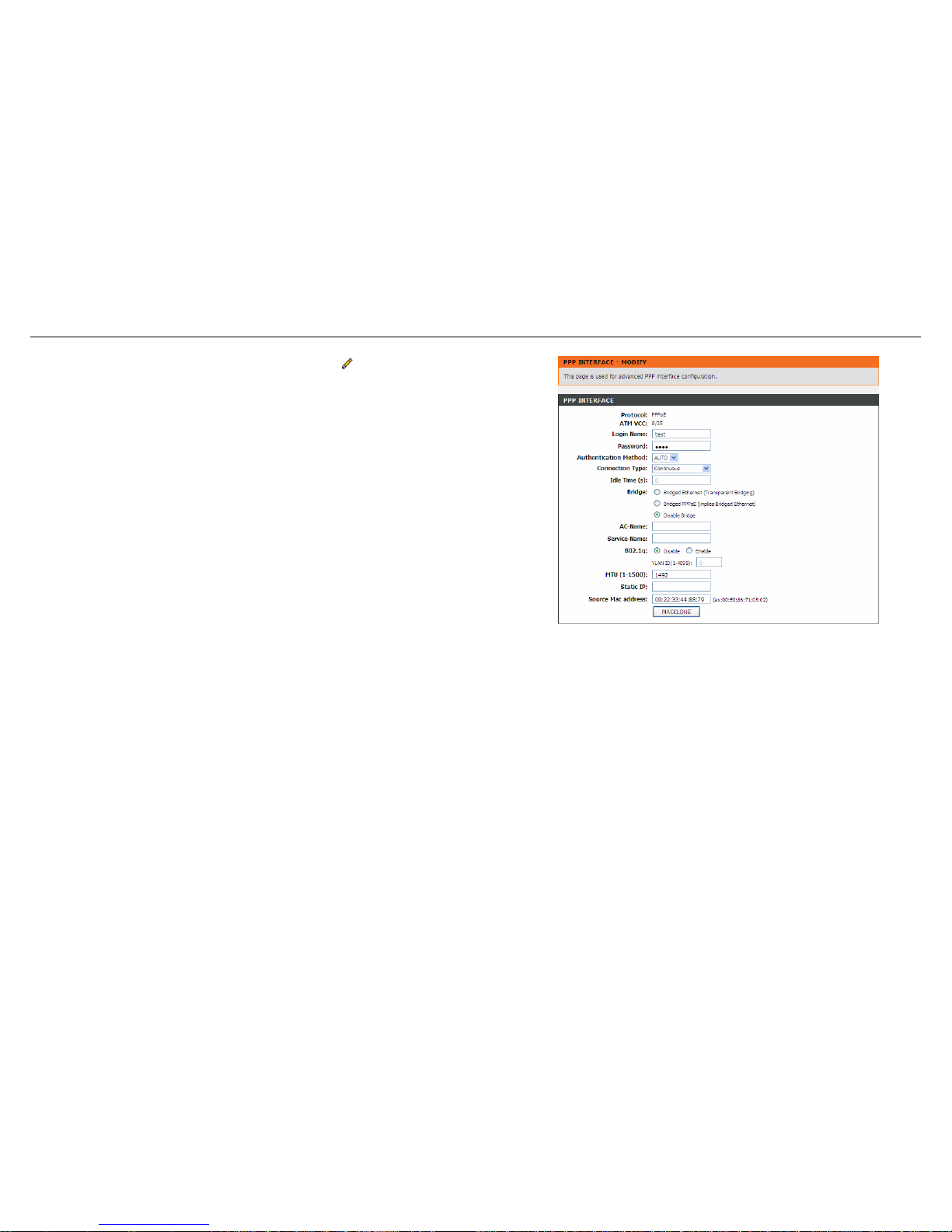
After a PPPoE ATM VC is added to the table, click in the PPPoE mode, the page
shown in the right figure appears. In this page, you can configure parameters of this
PPPoE PVC.
Configure the parameters in this page as described below.
Protocol: It displays the protocol type used for this WAN connection.
ATM VCC: The ATM virtual circuit connection assigned for this PPP interface
(VPI/VCI).
Login Name: The user name provided by your ISP.
Password: The password provided by your ISP.
Authentication Method: You can choose AUTO, CHAP, or PAP.
Connection Type: You can choose Continuous, Connect on Demand, or Manual.
Idle Time (s): If choose Connect on Demand, you need to enter the idle timeout
time. Within the preset minutes, if the router does not detect the flow of the user
continuously, the router automatically disconnects the PPPoE connection.
Bridge: You can select Bridged Ethernet, Bridged PPPoE, or Disable Bridge.
AC-Name: The accessed equipment type.
Service-Name: The service name.
D-Link DSL-526E User Manual 35
802.1q: You can select Disable or Enable. After enable it, you need to enter the
VLAN ID. The value ranges from 1 to 4095.
Source Mac address: The MAC address you want to clone.
MAC Clone: Click it to enable the MAC Clone function with the MAC address that is
configured.
Page 36
Configuration
ATM Settings
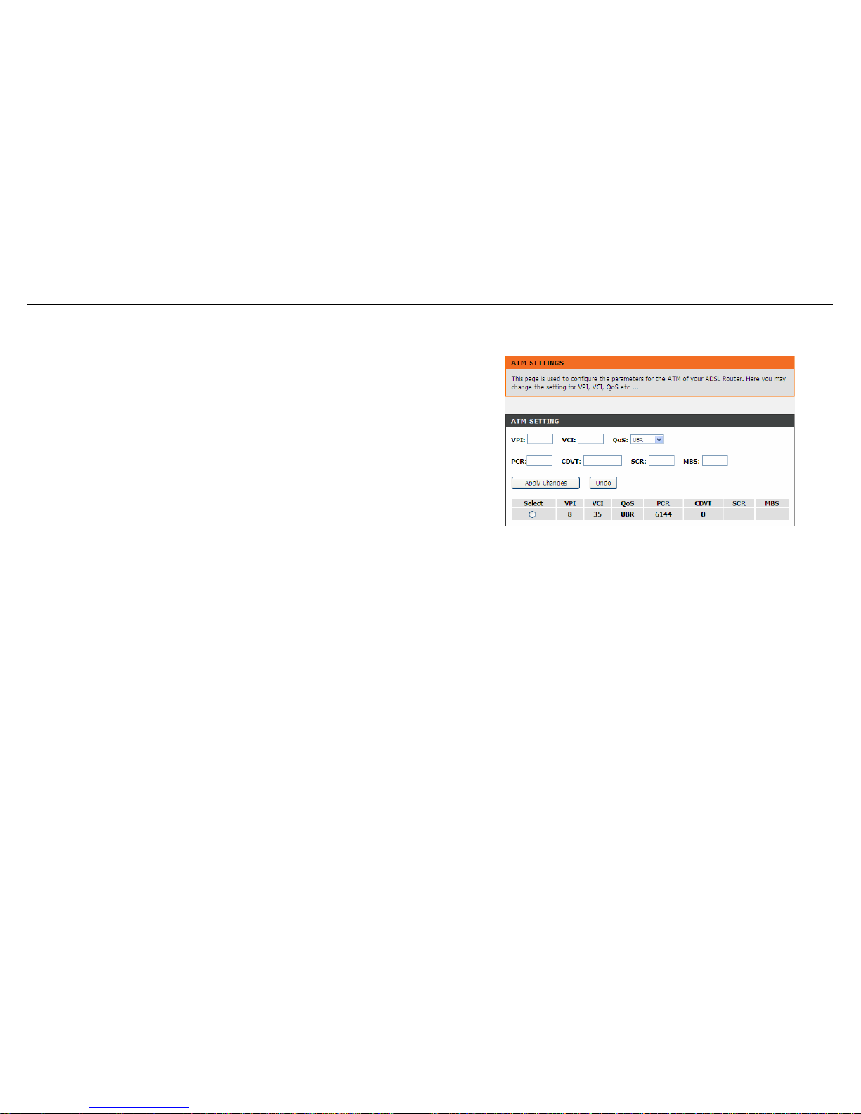
Choose Setup > Internet Setup > ATM Settings. The ATM Settings page appears.
You may configure the parameters for the ATM of your ADSL Router. Here you may
change the setting for VPI, VCI and QoS, etc.
Configure the parameters in this page as described below.
VPI: The virtual path identifier of the ATM PVC.
VCI: The virtual channel identifier of the ATM PVC.
QoS: The QoS category of the PVC. You can choose UBR, CBR, rt-VBR, or nrt-
VBR.
PCR: Peak cell rate (PCR) is the maximum rate at which cells can be transmitted
along a connection in the ATM network. Its value ranges from 1 to 65535.
CDVT: Cell delay variation tolerance (CDVT) is the amount of delay permitted
between ATM cells (in microseconds). Its value ranges from 0 to 4294967295.
SCR: Sustained cell rate (SCR) is the maximum rate that traffic can pass over a PVC
without the risk of cell loss. Its value ranges from 0 to 65535.
MBS: Maximum burst size (MBS) is the maximum number of cells that can be
transmitted at the PCR. Its value ranges from 0 to 65535.
36 D-Link DSL-526E User Manual
Page 37
Configuration
ADSL Settings
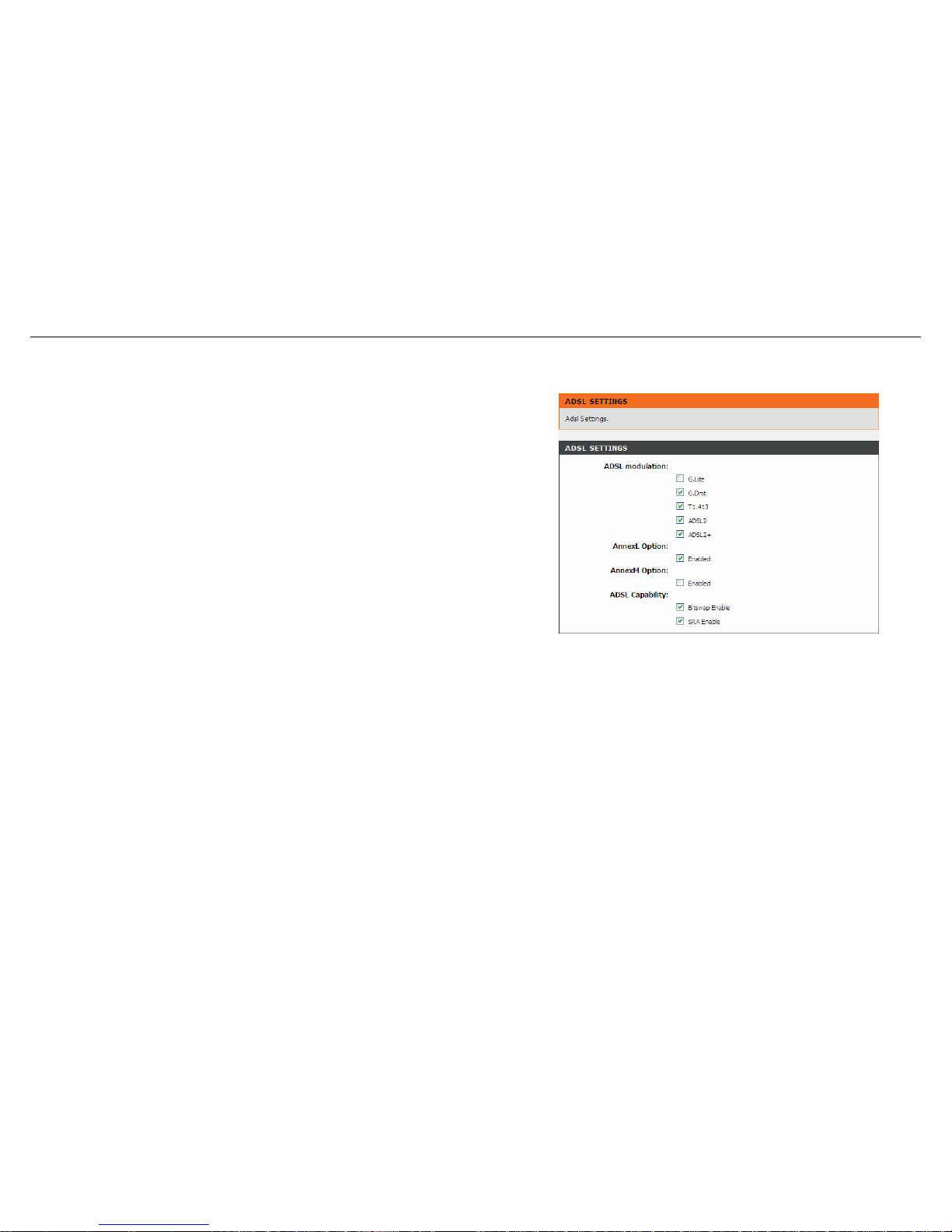
Choose Setup > Internet Setup > ADSL Settings. The ADSL Settings page
appears. This page contains a modulation and capability section to be specified by
your ISP. Consult with your ISP to select the correct settings for each. Click Apply
Changes to finish.
D-Link DSL-526E User Manual 37
Page 38
Configuration
PVC Auto Search
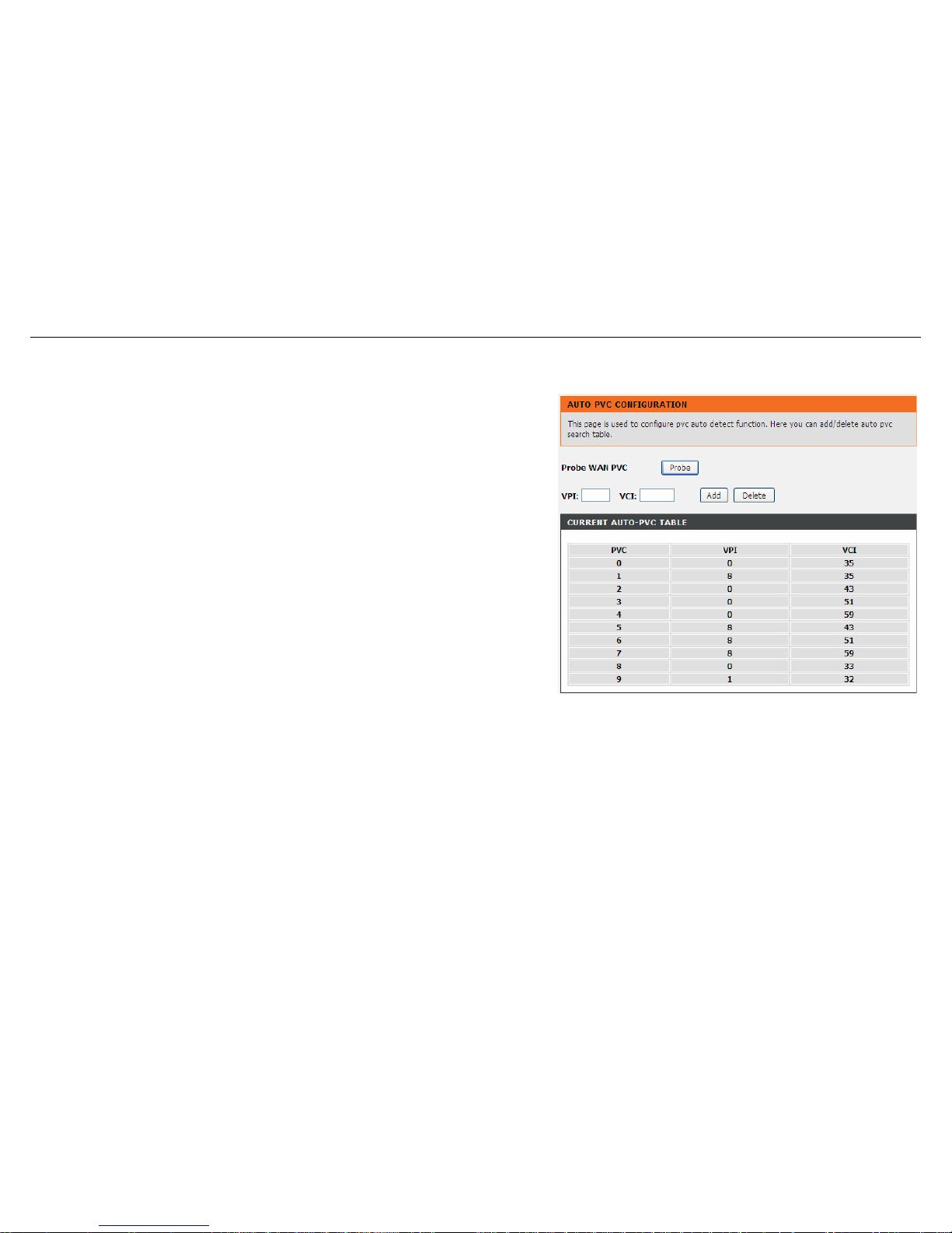
Choose Setup > Internet Setup > PVC Auto Search. The Auto PVC Configuration
page appears. You may configure PVC auto detect function. Here you can add/delete
auto PVC search table.
38 D-Link DSL-526E User Manual
Page 39
Configuration
Time and Date
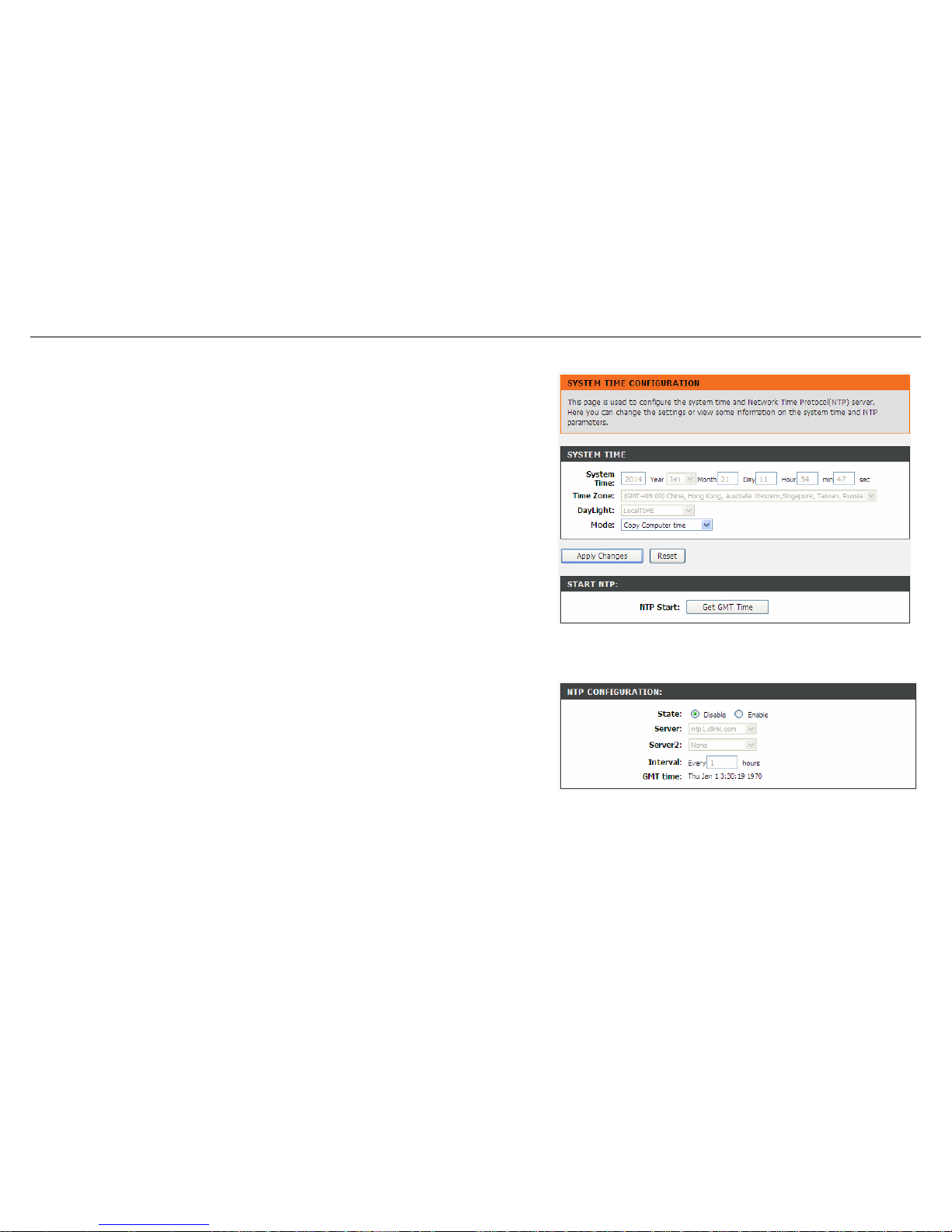
Choose Setup > Time and Date. The System Time Configuration page appears. In
the page, you can configure, update and maintain the correct time on the internal
system clock. You can set the time zone that you are in and the Network Time
Protocol (NTP) server. You can also configure daylight saving to automatically adjust
the time when needed.
Configure the parameters in this page as described below.
System Time: Displays the time currently maintained by the router. If this is incorrect,
use the following options to configure the time correctly.
Time Zone: Select your local time zone from the dropdown list.
Daylight: Adjust the clock for daylight savings time.
Mode: To synchronize the time automatically with the Internet or your own computer,
you may select Set Time Manually, Copy Computer Time or Set NTP Server
Manually.
Get GMT Time: Synchronize to Greenwich Mean Time.
When the mode is set to Set NTP Server Manually, the right page will appear.
Configure the parameters in this page as described below.
State: Select Enable to synchronize the time automatically with Internet or your own
computer.
Server: Select a Network Time Server for synchronization from the dropdown list. You
may set two servers.
Interval: Specify the interval for synchronization with the time server.
D-Link DSL-526E User Manual 39
Page 40

Configuration
40 D-Link DSL-526E User Manual
Advanced
This section includes advanced features for network management, security and administrative tools to manage the device. You can view status
and other information used to examine performance and for troubleshooting.
Access Control List
Multiple connections are required by some applications, for example, internet games, video conferencing and Internet telephony. These
applications have difficulties working through NAT (Network Address Translation). This section is used to open multiple ports or a range of ports in
your router and redirect data through those ports to a single PC on your network.
Page 41
Configuration
Access Control List
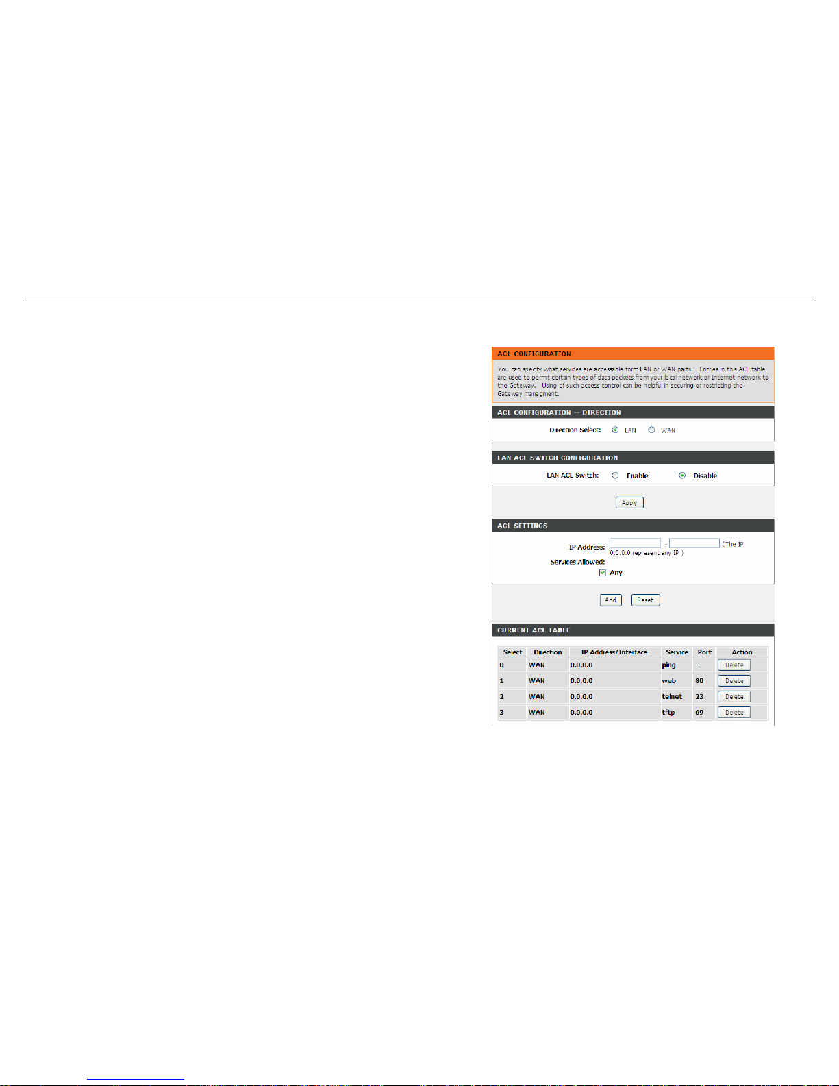
Choose Advanced > Access Control List > Access Control List. The page shown
in the right figure appears. In this page, you can permit the data packets from LAN or
WAN to access the router. You can configure the IP address for Access Control List
(ACL). If ACL is enabled, only the effective IP address in the ACL can access the
router.
Note: If you select Enable in ACL capability, ensure that your host IP address is in
ACL list before it takes effect.
Configure the parameters in this page as described below.
Direction Select: Select the router interface. You can select LAN or WAN. In this
example, LAN is selected.
LAN ACL Switch: Select it to enable or disable ACL function.
IP Address: Enter the IP address of the specified interface. Only the IP address that
is in the same network segment with the IP address of the specified interface can
access the router.
Services Allowed: You can choose the following services from LAN: Web, Telnet,
SSH, TFTP, SNMP and PING. You can also choose all the services.
Add: After setting the parameters, click it to add an entry to the Current ACL Table.
Reset: Click it to refresh this page.
D-Link DSL-526E User Manual 41
Page 42
Configuration
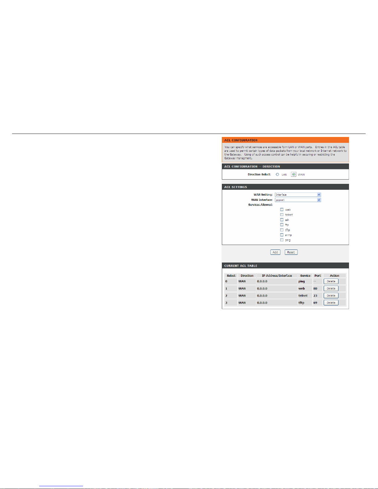
When the direction of data packets is set to WAN, the page shown in the right figure
appears.
Configure the parameters in this page as described below.
Direction Select: Select the router interface. You can select LAN or WAN. In this
example, WAN is selected.
WAN Setting: You can choose Interface or IP Address.
WAN Interface: Choose the interface that permits data packets from WAN to access
the router.
Services Allowed: You can choose the following services from WAN: Web, Telnet,
SSH, TFTP, SNMP and PING. You can also choose all the services.
Add: After setting the parameters, click it to add an entry to the Current ACL Table.
Reset: Click it to refresh this page.
42 D-Link DSL-526E User Manual
Page 43
Configuration
Access Control List IPv6
Choose Advanced > Access Control List > Access Control List IPv6. The page shown in the following figure appears. For configuration method,
refer to the section of Access Control List.
Port Triggering
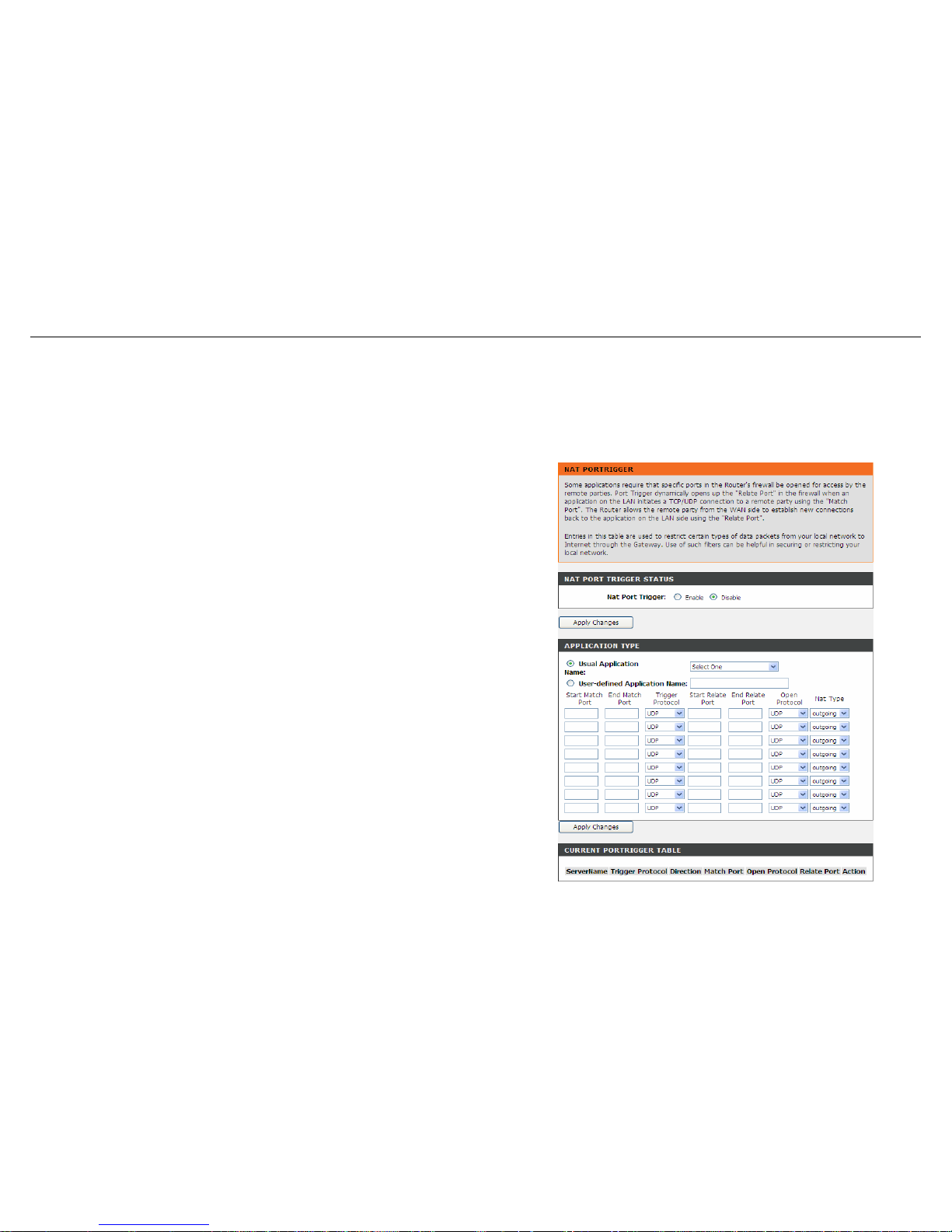
Choose Advanced > Port Triggering. The page shown in the right figure appears.
Port Triggering is a special form of Port Forwarding in which it requires an outgoing
connection before allowing incoming connections on a single or multiple ports. Port
Triggering is mostly used when your computer is behind a NAT router. It gives more
flexibility than static port forwarding because you don't need to set it up for a specific
computer.
Click the Usual Application Name drop-down menu to choose the application you
want to set up for port triggering. When you have chosen an application the default
Trigger settings will populate the table below.
If the application you want to set up isn’t listed, click the User-defined Application
Name radio button and type in a name for the trigger in the Custom application field.
Configure the Start Match Port, End Match Port, Trigger Protocol, Start Relate
Port, End Relate Port, Open Protocol and Nat type.
Click the Apply changes button to finish.
D-Link DSL-526E User Manual 43
Page 44
Configuration
Port Forwarding
This function is used to open ports in your device and redirect data through those ports to a single PC on your network (WAN-to-LAN traffic). It
allows remote users to access services on your LAN, such as FTP for file transfers or SMTP and POP3 for e-mail. The device accepts remote
requests for these services at your global IP address. It uses the specified TCP or UDP protocol and port number, and redirects these requests to
the server on your LAN with the LAN IP address you specify. Note that the specified private IP address must be within the available range of the
subnet where the device is in.
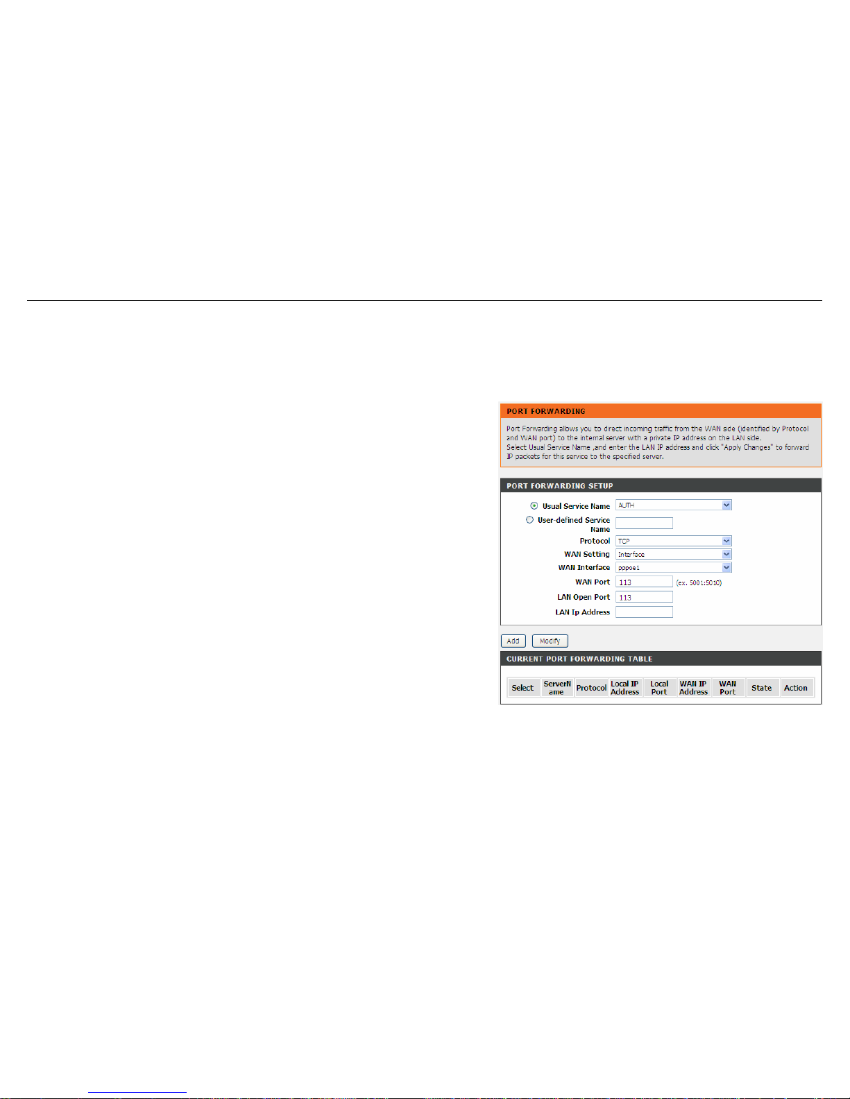
Choose Advanced > Port Forwarding. The page shown in the right figure appears.
Click the Usual Service Name drop-down menu to choose the service you want to
set up for port forwarding. When you have chosen a service, the default settings will
populate the table below.
If the service you want to set up isn’t listed, select the User-defined Service Name
radio button and type in a service name. Configure the Protocol, WAN Setting,
WAN Interface, WAN Port, LAN Open Port and LAN IP Address.
Click the Apply changes button to finish.
44 D-Link DSL-526E User Manual
Page 45
Configuration
DMZ
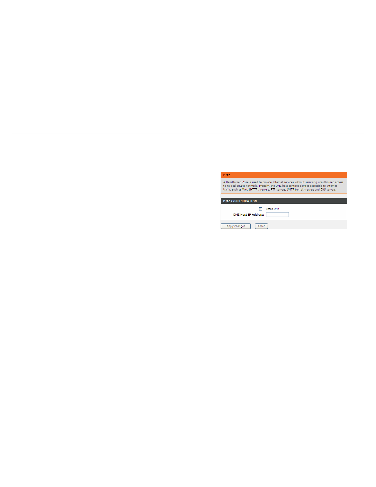
DMZ is the abbreviation of the Demilitarized Zone. Since some applications are not compatible with NAT, the device supports the use of a DMZ IP
address for a single host on the LAN. This IP address is not protected by NAT and it is visible to agents on the Internet with the correct type of
software. Note that any client PC in the DMZ is exposed to various types of security risks. If you use the DMZ, take measures (such as client-based
virus protection) to protect the remaining client PCs on your LAN from possible contamination through DMZ.
Choose Advanced > DMZ. The page shown in the right figure appears.
In the DMZ Host IP Address, input the LAN IP address of the LAN computer that you
want to have unrestricted Internet communication. If this computer obtains its address
automatically using DHCP, then you may want to make a static reservation on the
Setup-->Local Network-->DHCP Reserved page so that the IP address of the DMZ
computer does not change.
Click Apply to save the settings.
D-Link DSL-526E User Manual 45
Page 46
Configuration
Parent Control
You may create a list of websites that you would like the devices on your network to be denied access to. URL Block allows you to quickly create a
list of all websites that you wish to stop users from accessing. MAC Filter allows you to control when clients or PCs connected to the device are
allowed to access the Internet.
URL Block
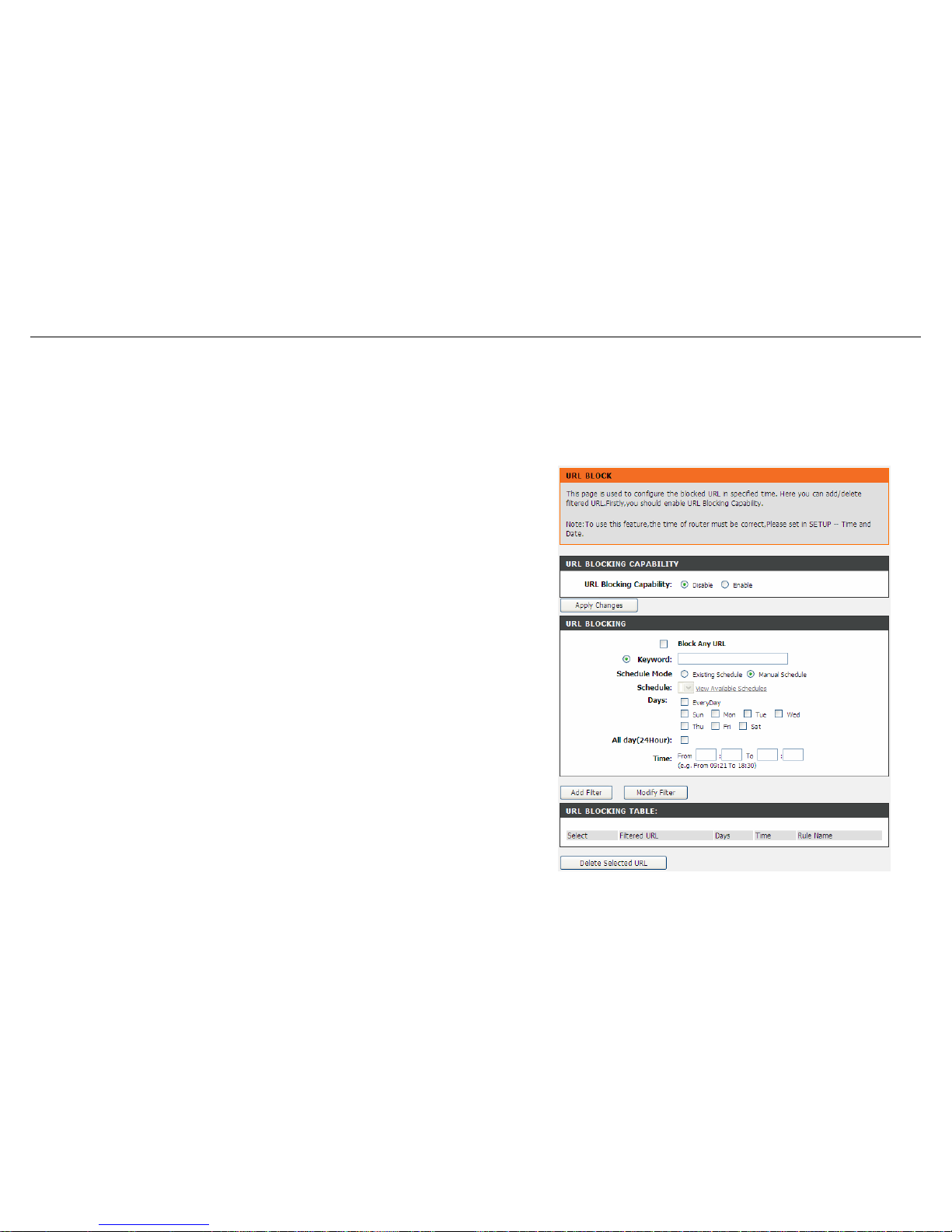
Choose Advanced > Parental Control > URL Block. The URL Block page shown in
the right figure appears. You may deny certain websites from being accessed during
the "schedule" you specified. Here you can add/delete filtered URL.
Note: To use this feature, the time of router must be correct. Please set in the section
of Time and Date.
In the field Schedule Mode, you may select an existing schedule schedule for when
the rule will be enabled, or manually set a schedule. After setting, click Add Filter to
add the URL into the URL Blocking Table. To add schedules, refer to the section of
Schedules.
46 D-Link DSL-526E User Manual
Page 47
Configuration
MAC Block
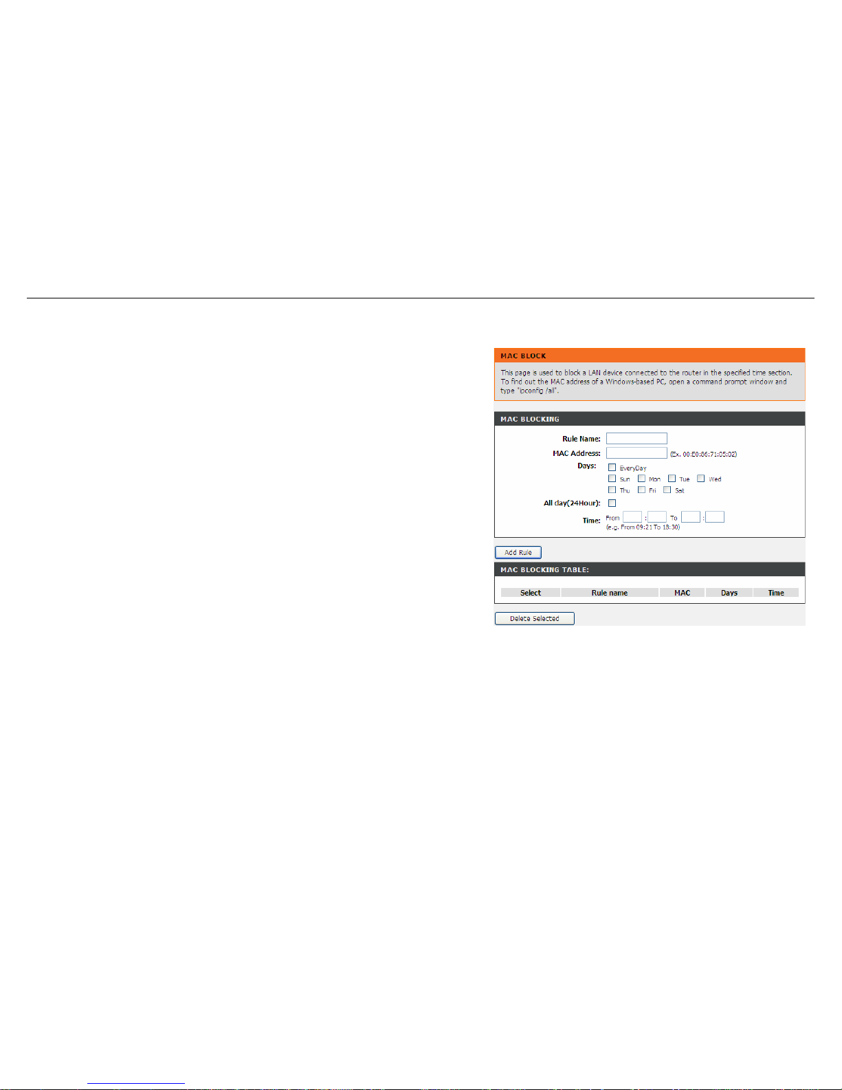
Choose Advanced > Parental Control > MAC Block. The URL Block page shown
in the right figure appears. You may block a LAN device connected to the router in the
specified time section.
In the field Rule Name, input a name that is meaningful to you, then enter a MAC
address that you want to deny access to the Internet, and set the days and hours,
and click Add Rule to add the MAC into the MAC Blocking Table.
D-Link DSL-526E User Manual 47
Page 48
Configuration
Schedules
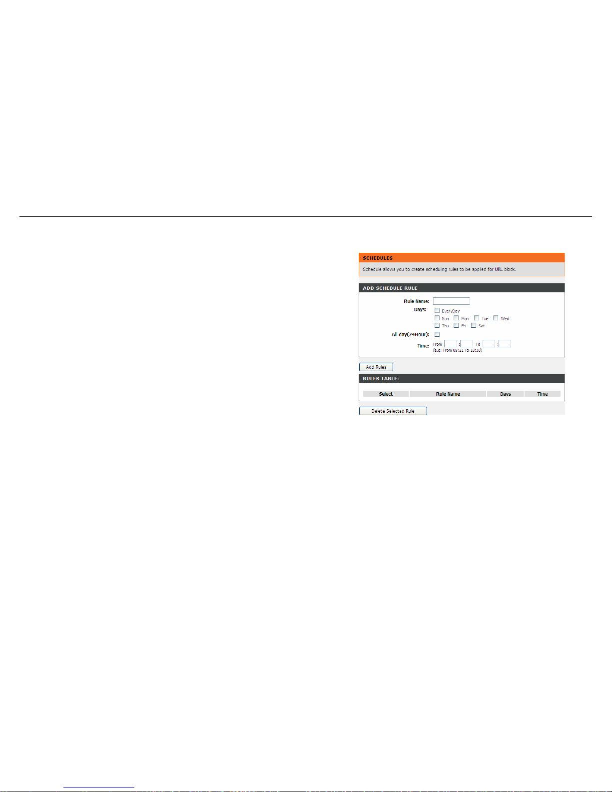
Choose Advanced > Parental Control > Schedules. The Schedules page shown in
the right figure appears. You may add or delete scheduling rules to be applied for
URL block.
In the field Rule Name, give the schedule a name that is meaningful to you, such as
"Weekday rule". Set the Day(s) and time field, and click Add Rules to save the new
rule in the following Rules Table.
48 D-Link DSL-526E User Manual
Page 49
Configuration
Filtering Options
Filters can be configured to manage your incoming and outgoing traffic.
IP/Port Filter
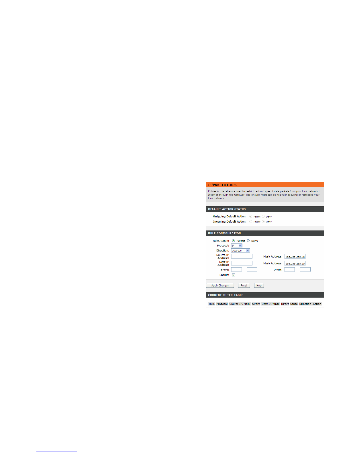
When you use the Port Triggering or Port Forwarding features to open specific ports to traffic from the Internet, you could be increasing the
exposure of your LAN to cyber-attacks from the Internet. In these cases, you can limit that exposure by specifying the IP addresses of Internet hosts
that you trust to access your LAN through the ports that you have opened.
Choose Advanced > Filtering Options > IP/Port Filter. The IP/Port Filtering page
shown in the right figure appears.
Direction Upstream (Downstream) means packets outgoing (incoming) from (to)
router. The Source IP addresses are LAN-side (WAN-side) addresses and the
Destination IP addresses are WAN-side (LAN-side) addresses. Select the rule action,
specify at least one of the following criteria: protocol, source/destination IP address,
subnet mask and source/destination port.
Click the Apply Changes to save a finished rule in the Rules List. The Current Filter
Table shows detailed information about each created IP filter.
Note: The settings only apply when the firewall is enabled.
D-Link DSL-526E User Manual 49
Page 50
Configuration
IPv6/Port Filter
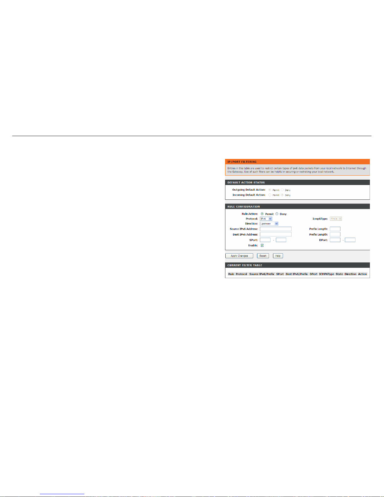
Choose Advanced > Filtering Options > IPv6/Port Filter. The IP/Port Filtering
page shown in the right figure appears. You may restrict certain types of ipv6 data
packets between LAN-side and WAN-side.
For detailed configuration, you may refer to the section of IP/Port Filter.
50 D-Link DSL-526E User Manual
Page 51
Configuration
MAC Filter
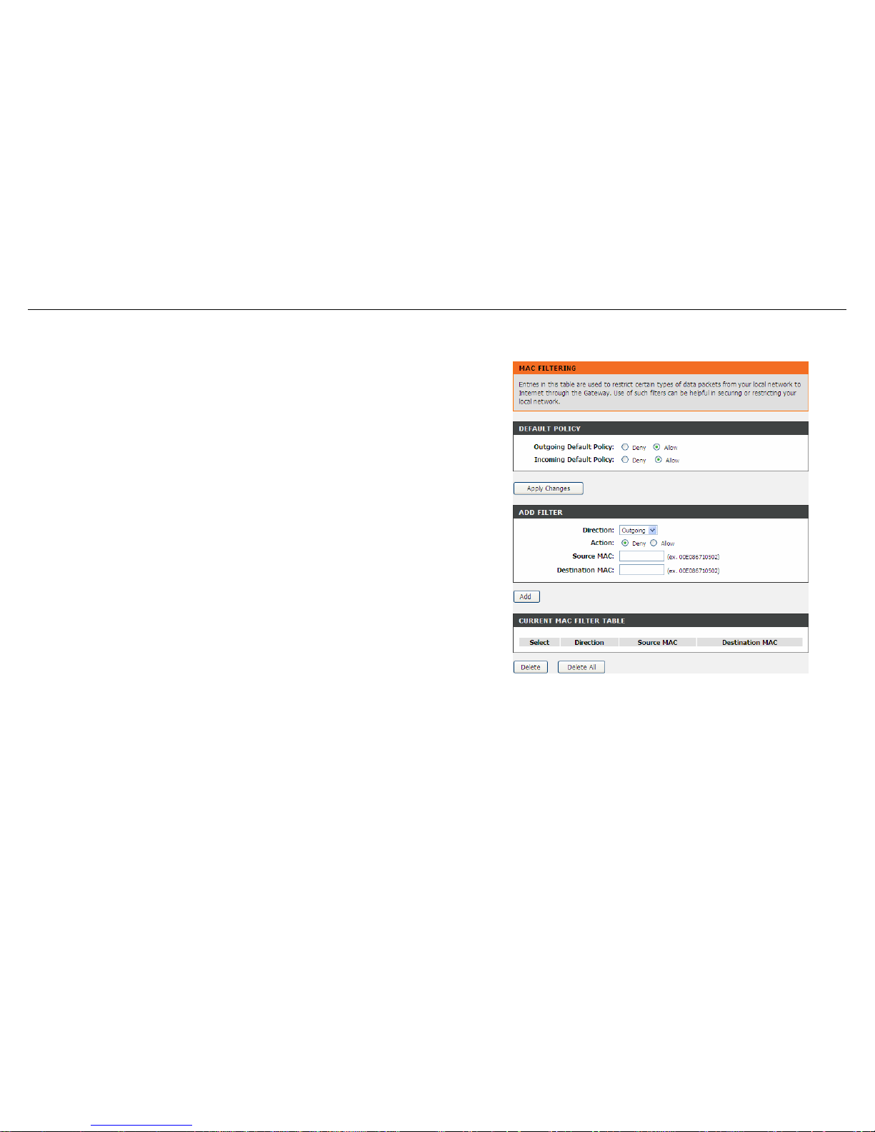
Choose Advanced > Filtering Options > MAC Filter. The MAC Filtering page
shown in the right figure appears. You may create a list of MAC addresses that you
would either like to allow or deny access to your network.
D-Link DSL-526E User Manual 51
Page 52
Configuration
DoS Settings
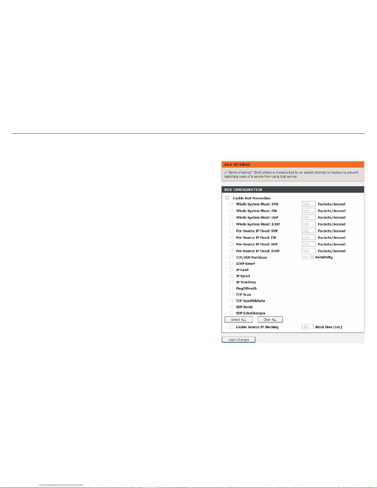
Denial-of-Service Attack (DoS attack) is a type of attack on a network that is designed to bring the network to its knees by flooding it with useless
traffic.
Choose Advanced > DoS Settings. The DOS Settings page shown in the right
figure appears. Select the Enable DoS Prevention checkbox, select the options
below, and click Apply Changes to finish.
52 D-Link DSL-526E User Manual
Page 53
Configuration
DNS
Domain Name System (DNS) is an Internet service that translates the URL/domain name into the corresponding IP address. Since URL/Domain
Names are alphabetical, they are easier to remember. But the Internet is based on IP address. For example, the URL/Domain Name www.dlink.com
is actually 192.168.0.123.
DNS
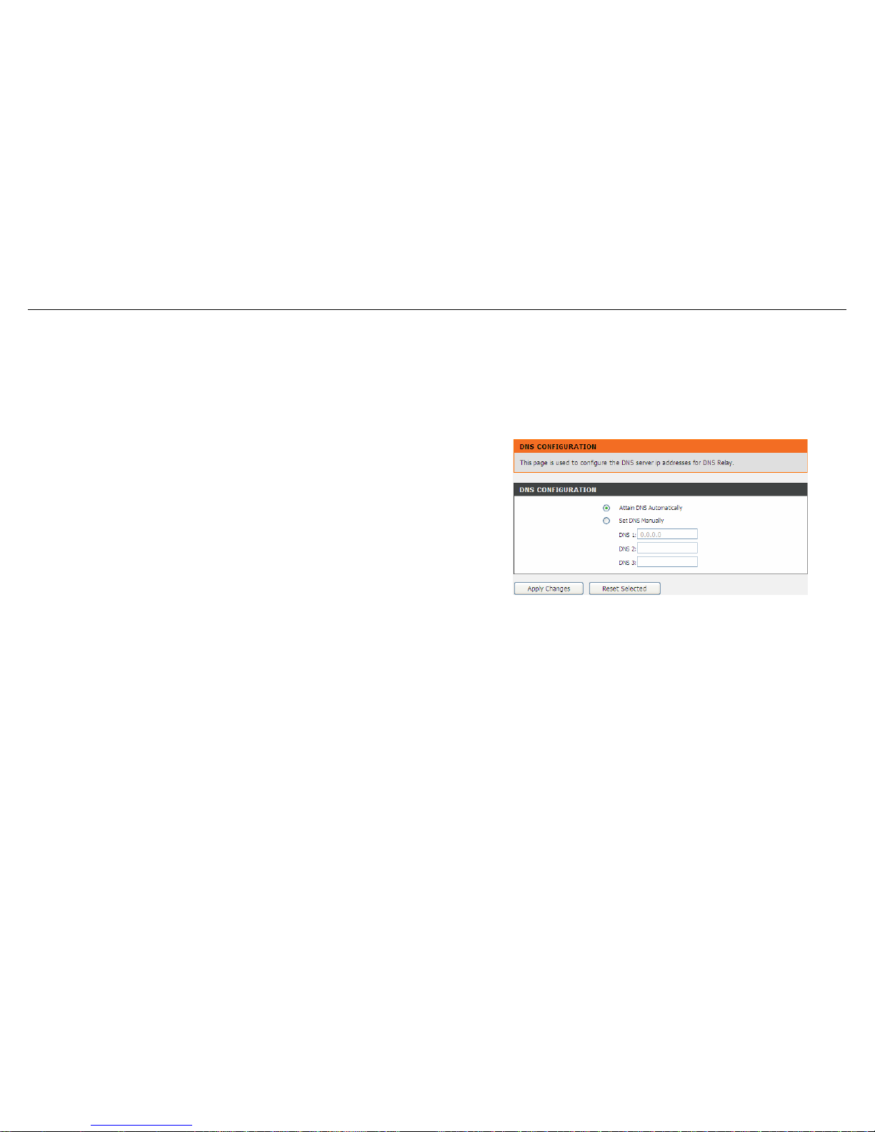
Choose Advanced > DNS > DNS. The DNS Configuration page shown in the right
figure appears. You may configure the IP addresses of DNS servers for DNS Relay.
Configure the parameters in this page as described below.
Attain DNS Automatically: Select it, the router accepts the first received DNS
assignment from one of the PPPoA, PPPoE or MER enabled PVC(s) during the
connection establishment.
Set DNS Manually: Select it, enter the IP addresses of the primary and secondary
DNS server.
Apply Changes: Click it to save the settings of this page.
Reset Selected: Click it to start configuring the parameters in this page.
53 D-Link DSL-526E User Manual
Page 54
Configuration
IPv6 DNS
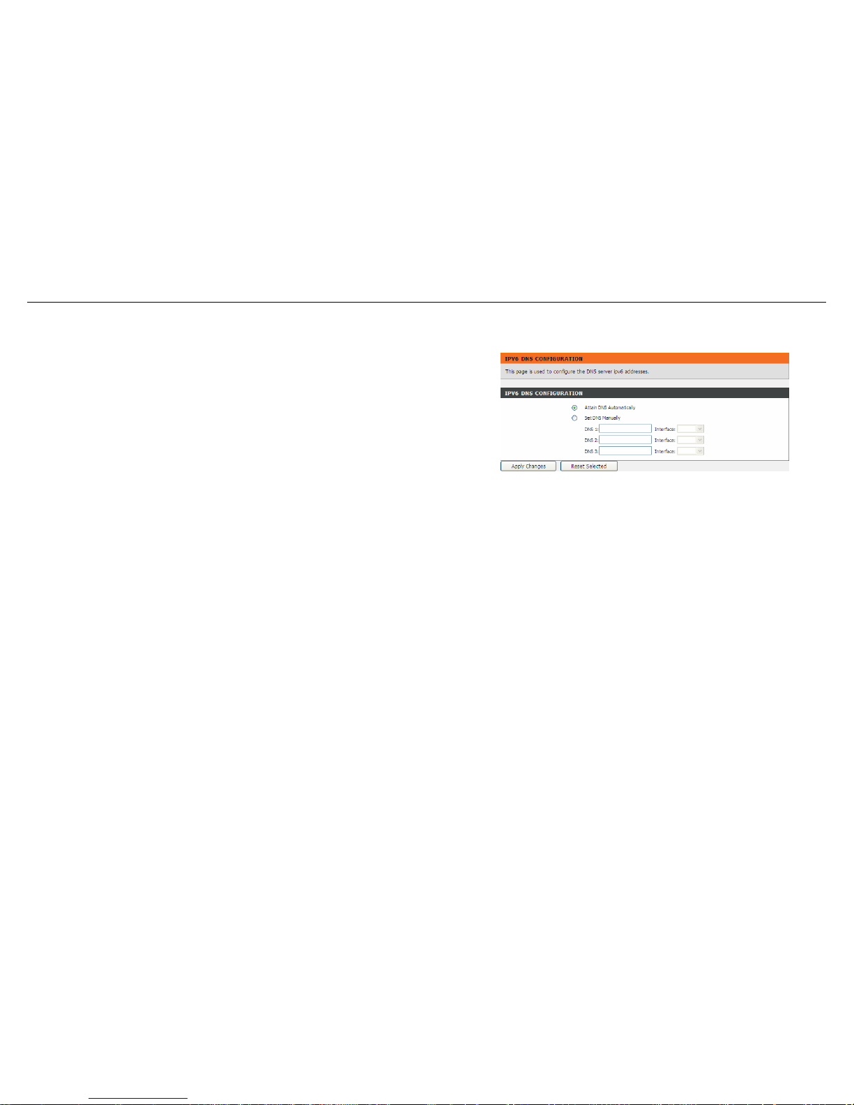
Choose Advanced > DNS > IPv6 DNS. The IPv6 DNS Configuration page shown in
the right figure appears. You may configure the ipv6 addresses of DNS servers.
Configure the parameters in this page as described below.
Attain DNS Automatically: Select it, the router accepts the first received DNS
assignment from one of the PPPoA, PPPoE or MER enabled PVC(s) during the
connection establishment.
Set DNS Manually: Select it, enter the IP addresses and choose the WAN interface
of the primary, the secondary and the tertiary DNS server.
Interface: The router accepts received packet assignment from one of the PPPoA,
PPPoE or MER enabled PVC(s).
Apply Changes: Click it to save the settings of this page.
Reset Selected: Click it to start configuring the parameters in this page.
Dynamic DNS
The device supports dynamic domain name service (DDNS). The dynamic DNS service allows a dynamic public IP address to be associated with a
static host name in any of the many domains, and allows access to a specified host from various locations on the Internet. Click a hyperlinked URL
in the form of hostname.dyndns.org and allow remote access to a host. Many ISPs assign public IP addresses using DHCP, so locating a specific
host on the LAN using the standard DNS is difficult. For example, if you are running a public web server or VPN server on your LAN, DDNS ensures
that the host can be located from the Internet even if the public IP address changes. DDNS requires that an account be set up with one of the
supported DDNS service providers (DyndDNS.org or dlinkddns.com).
54 D-Link DSL-526E User Manual
Page 55
Configuration
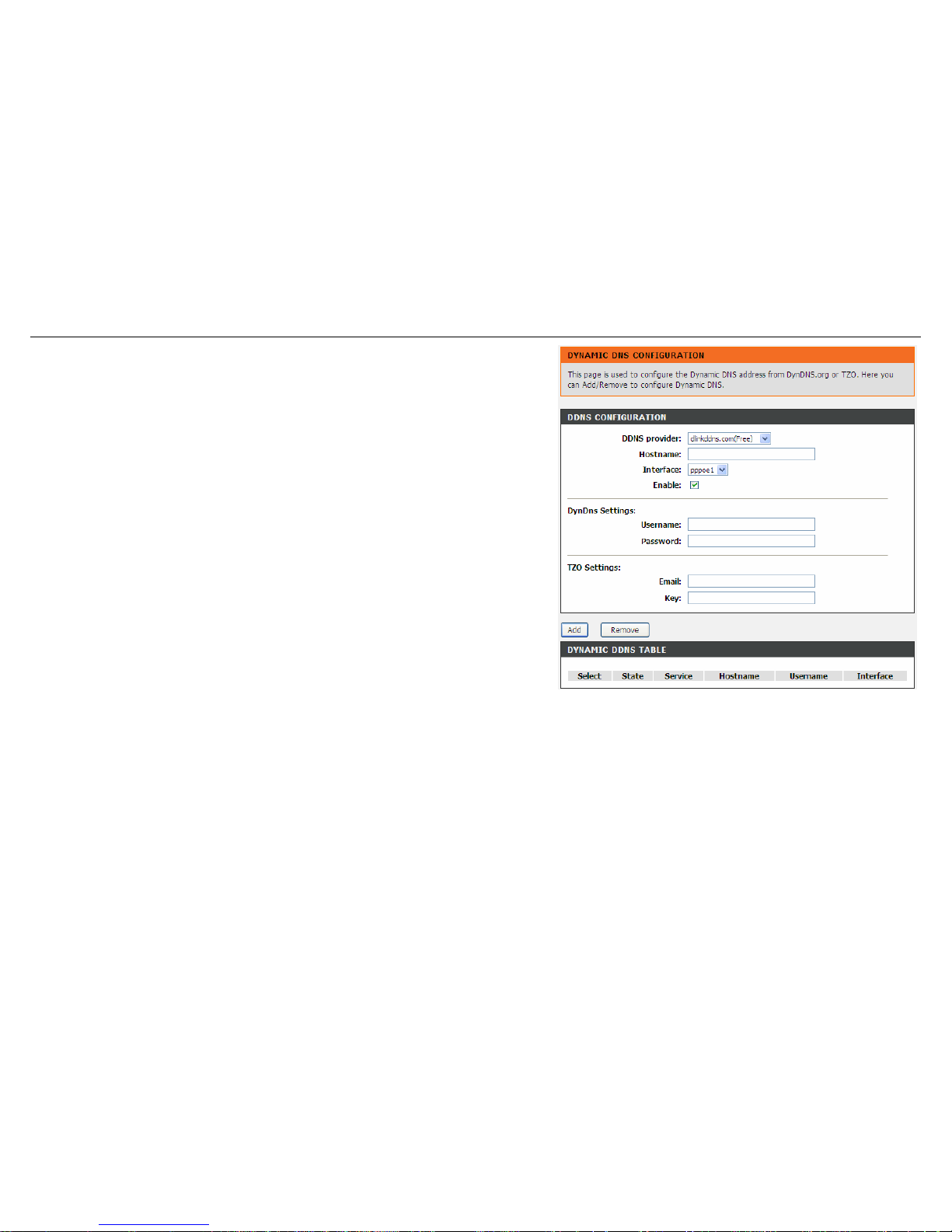
Choose Advanced > Dynamic DNS. The Dynamic DNS Configuration page shown
in the right page appears.
Configure the parameters in this page as described below.
DDNS provider: Select a dynamic DNS service provider from the pull-down list.
Hostname: Enter the host name that you registered with your DDNS service provider.
Username: Enter the username provided by your service provider.
Password: Enter the password provided by your service provider.
Click Add to save the settings to the Dynamic DDNS Table.
Note: In some cases DDNS service requires you to open the WAN http service. Refer
to Access Control List-> Access Control List.
Network Tools
The router provides following tools: Port Mapping, IGMP Proxy, IP QoS, UPnP, SNMP, TR-069, Software Forbidden, ARP Binding, Client Limit,
and Telnet.
Port Mapping
Port Mapping supports a single (LAN) port or multiple (LAN) ports to be formed as a group and mapped to a PVC (which is associated w/ a VLAN).
As a result, each group of LAN ports will perform as an independent (logical) network (like a broadcast domain) among whom traffic broadcast
would be prevented. This feature is useful while you would like to form multiple independent (logical) networks for multimedia applications at home.
For instance, you can map PVC1 to port 1~3 to create a network (broadcast domain) for PCs for Internet, and map PVC2 to port 4 to create another
network (broadcast domain) for IPTV service (devices). By using this feature (w/ multiple PVCs), data traffic and IPTV traffic would not affect each
D-Link DSL-526E User Manual 55
Page 56
Configuration
other.
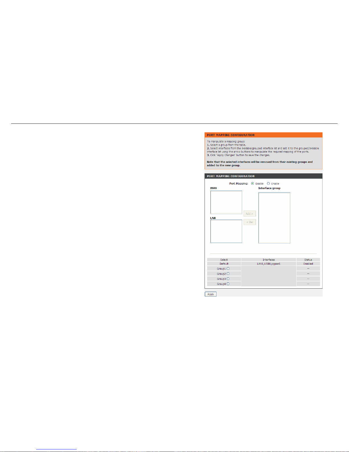
Choose Advanced > Network Tools > Port Mapping. The Port Mapping
Configuration page shown in the right figure appears.
Follow the steps to manipulate a mapping group.
Step 1 Select a group from the table.
Step 2 Select interfaces from the available WAN and LAN interface groups and add
it to the interface group list using the arrow buttons to manipulate the
required mapping of the ports.
Step 3 Click Apply button to save the changes.
Note: The selected interfaces will be removed from their existing groups and added
to the new group.
IGMP Proxy
IGMP allows support for efficient multicasting -- transmission of identical content, such as multimedia, from a source to a number of recipients.
56 D-Link DSL-526E User Manual
Page 57
Configuration
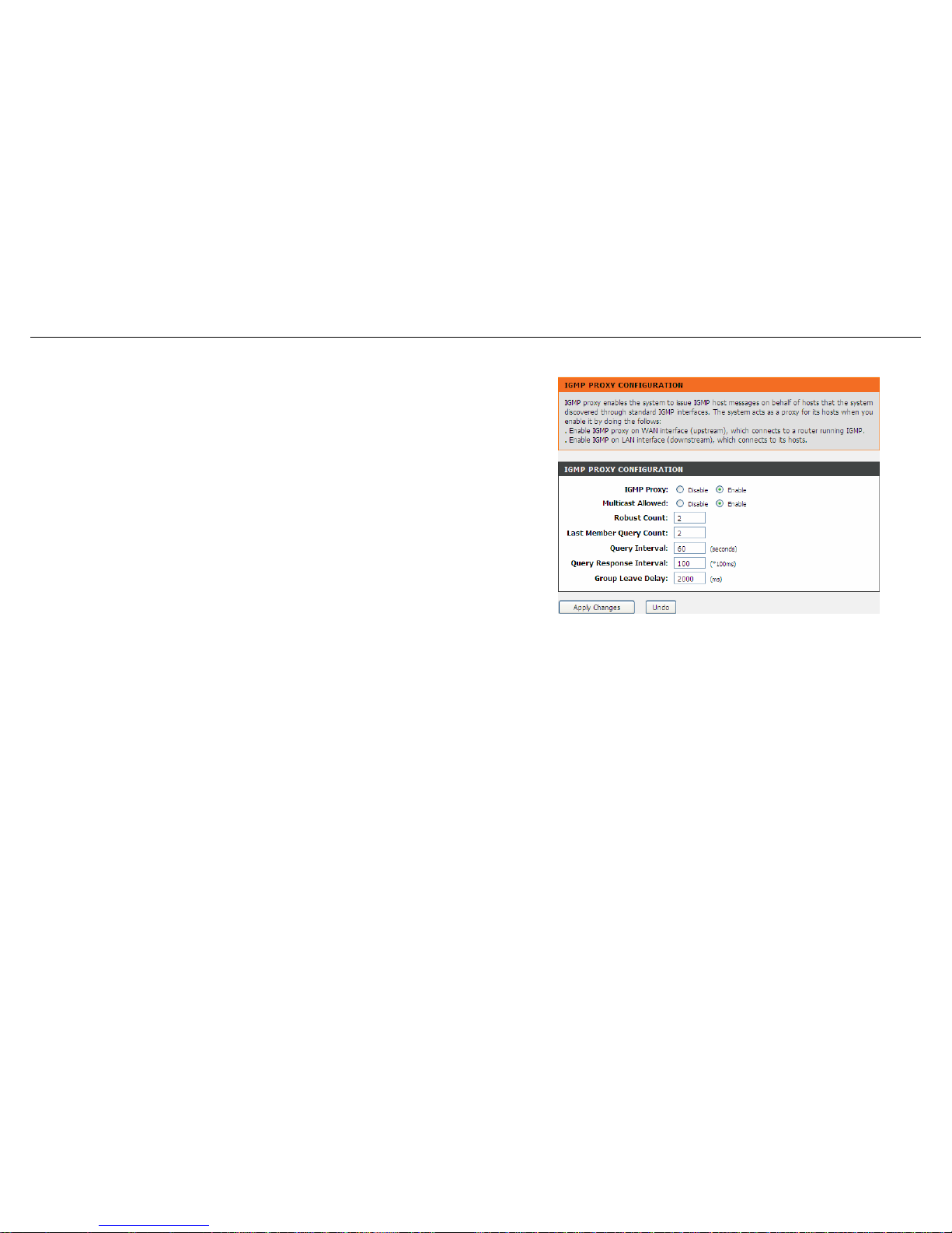
IGMP proxy enables the system to issue IGMP host messages on behalf of hosts that the system discovered through standard IGMP interfaces.
The system acts as a proxy for its hosts when you enable it.
Choose Advanced > Network Tools > IGMP Proxy. The IGMP Proxy
Configuration page shown in the right figure appears.
Configure the parameters in this page as described below.
Multicast allowed: Enable multicast proxy, only for route mode.
Robust Count: Allows tuning for the expected packet loss on a link. It determines
how many times a startup query should be xmitted.
Last Member Query Count: This parameter specifies the times the device sends the
query message.
Query Interval: The device sends query messages to check IGMP user periodically.
The unit is second.
Query Response Interval: The device waits for the IGMP user’s reply. The unit is
100 * millisecond.
Group Leave Delay: The duration for the modem to cease forwarding multicast
packets after a corresponding IGMP "Leave Group" message has been successfully
offered to the modem.
Click Apply Changes to save the settings.
IP QoS
Quality of Service is a feature that allows you to allocate or guarantee the throughput or speed of Internet for certain computers. This is a very
useful feature for sensitive applications such as VoIP whereby it will assist in preventing dropped calls. Large amounts of non-critical data can be
scaled so that they do not affect sensitive real-time applications such as VoIP or Streaming.
D-Link DSL-526E User Manual 57
Page 58
Configuration
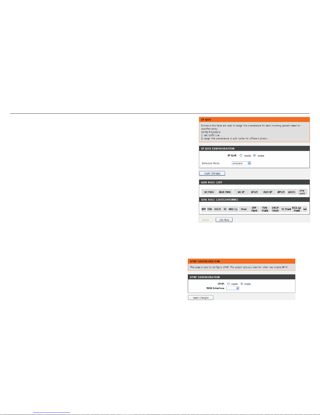
Choose Advanced > Network Tools > IP QoS. The IP QoS page shown in the right figure
appears. Entries in the QoS Rule List are used to assign the precedence for each
incoming packet based on physical LAN port, TCP/UDP port number, source IP address,
destination IP address and other information.
Step 1 Enable IP QoS and click Apply to enable IP QoS function.
Step 2 Click add rule to add a new IP QoS rule.
UPnP
UPnP (Universal Plug and Play) is a networking architecture that provides compatibility among networking equipment, software, and peripherals.
This router has optional UPnP capability, and can work with other UPnP devices and software. The system acts as a daemon when you enable
UPnP. Leave the UPnP option enabled as long as the LAN has other UPnP applications.
Choose Advanced > Network Tools > UPnP. The UPnP Configuration page
shown in the right figure appears.
58 D-Link DSL-526E User anual M
Page 59
Configuration
SNMP
SNMP (Simple Network Management Protocol) provides a means to monitor status
and performance and set configuration parameters. It enables a management station
to configure, monitor and receive trap messages from network devices.
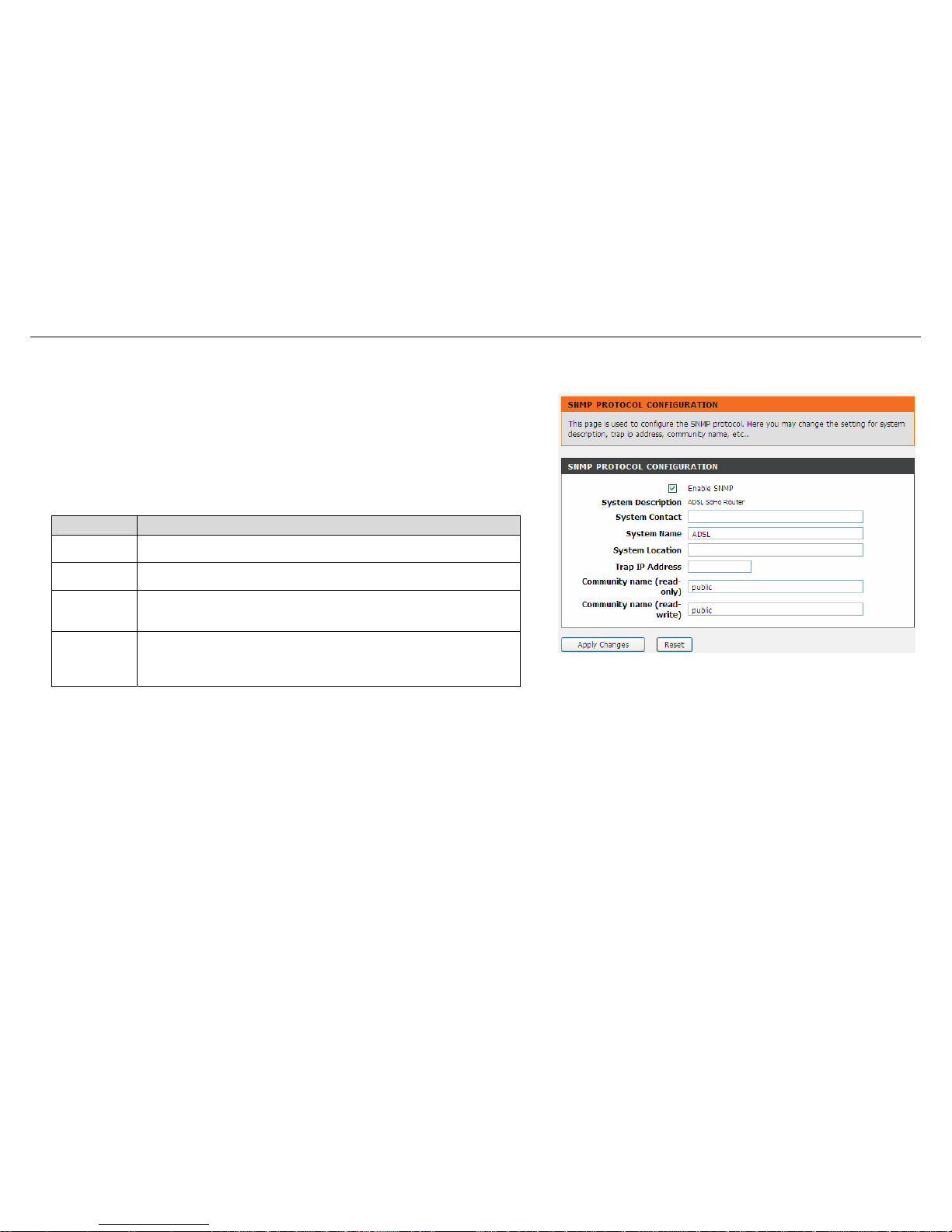
Choose Advanced > Network Tools > SNMP. The SNMP Protocol Configuration
page shown in the right figure appears. You may change the settings for system
description, trap IP address and community name.
The following table describes the parameters of this page:
Field
Description
Enable
SNMP
Select it to enable SNMP function. You need to enable SNMP,
and then you can configure the parameters of this page.
Trap IP
Address
Enter the trap IP address. The trap information is sent to the
corresponding host.
Community
Name
(Read-only)
The network administrators must use this password to read
the information of this router.
Community
Name
(Read-
Write)
The network administrators must use this password to
configure the information of the router.
TR-069
TR-069 is a WAN management protocol. It is a bidirectional SOAP/HTTP based protocol providing the communication between the ADSL router and
an Auto Configuration Server (ACS) to monitor status and performance and to set configuration parameters from WAN side.
D-Link DSL-526E User Manual 59
Page 60
Configuration
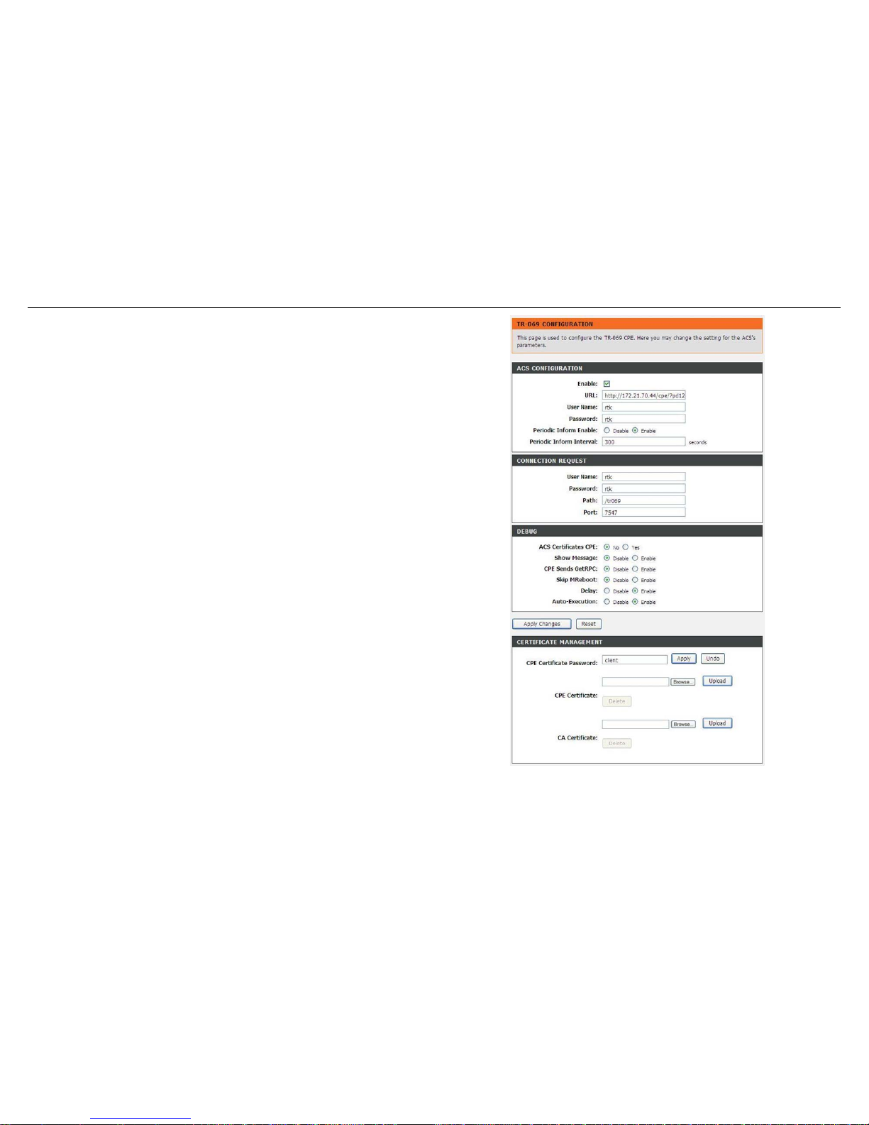
Choose Advanced > Network Tools > TR-069. The TR-069 Configuration page
shown in the right figure appears. You may change change the setting for the ACS's
parameters
Configure the parameters in this page as described below.
ACS Configuration
URL: The URL of the auto-configuration server to connect to.
User Name: The user name for logging in to the ACS.
Password: The password for logging in to the ACS.
Periodic Inform Enable: Select Enable to periodically connect to the ACS to check
configuration updates.
Periodic Inform Interval: Specify the amount of time between connections to ACS.
Connection Request
User Name: The connection username provided by TR-069 service.
Password: The connection password provided by TR-069 service.
Debug
Show Message: Select Enable to display ACS SOAP messages on the serial
console.
CPE sends GetRPC: Select Enable, the router contacts the ACS to obtain
configuration updates.
Skip MReboot: Specify whether to send an MReboot event code in the inform
message.
Delay: Specify whether to start the TR-069 program after a short delay.
Auto-Execution: Specify whether to automatically start the TR-069 after the router is
powered on.
Certificate Management
CPE Certificate Password: The certificate password of the router.
CPE Certificate: Enter the CPE Certificate file. Click it to browse and upload the
certificate for the router.
CA Certificate: Click it to browse and upload the CA certificate for the router.
60 D-Link DSL-526E User Manual
Page 61
Configuration
Software Forbidden
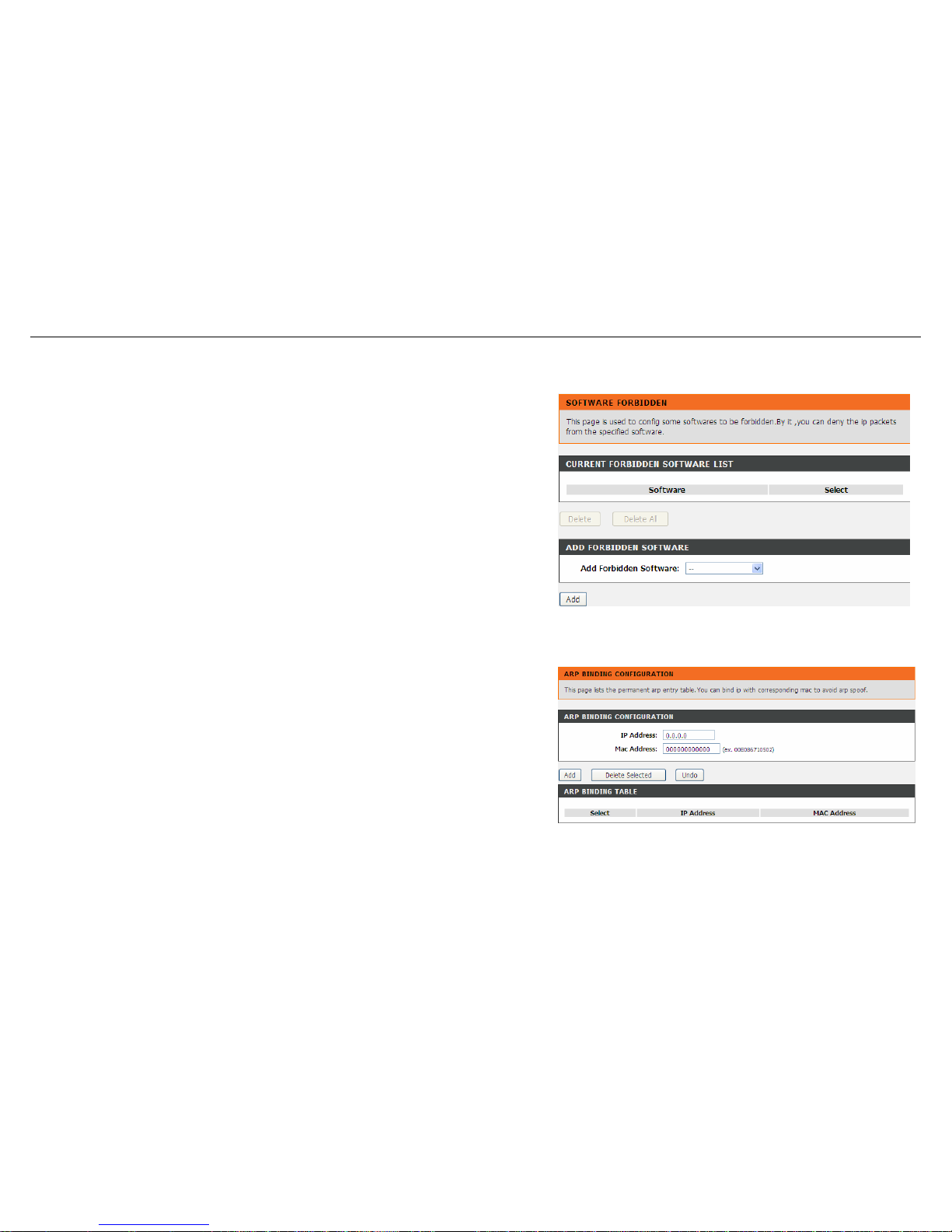
Choose Advanced > Network Tools > Software Forbidden. The Software
Forbidden page shown in the right figure appears. You may config some software to
be forbidden to deny the ip packets of it.
To forbid one specified PC (or some PCs) from using an application, select the
application you want to prohibit, and input a single IP address or IP addresses in
range. When Single IP is selected, IP 0.0.0.0 represent for any IP. In this situation, all
PCs connected to this router will deny the selected software.
Configure the parameters in this page as described below.
Current Forbidden Software List: A list of currently forbidden applications for
accessing the network.
Add Forbidden Software: Select an application to be forbidden from accessing the
network.
ARP Binding
This function realizes the binding of IP addresses and MAC addresses to avoid ARP
address cheats. Choose Advanced > Network Tools > ARP Binding. The ARP
Binding Configuration page shown in the right figure appears.
Configure the parameters in this page as described below.
IP Address: An IP address to be bound.
Mac Address: An MAC address to be bound.
Add: Click this icon to add an ARP binding.
Delete Selected: Delete a selected setting from the list.
Undo: Reconfigure the above setting.
ARP Binding Table: A list of all the current ARP binding settings.
D-Link DSL-526E User Manual 61
Page 62
Configuration
Client Limit
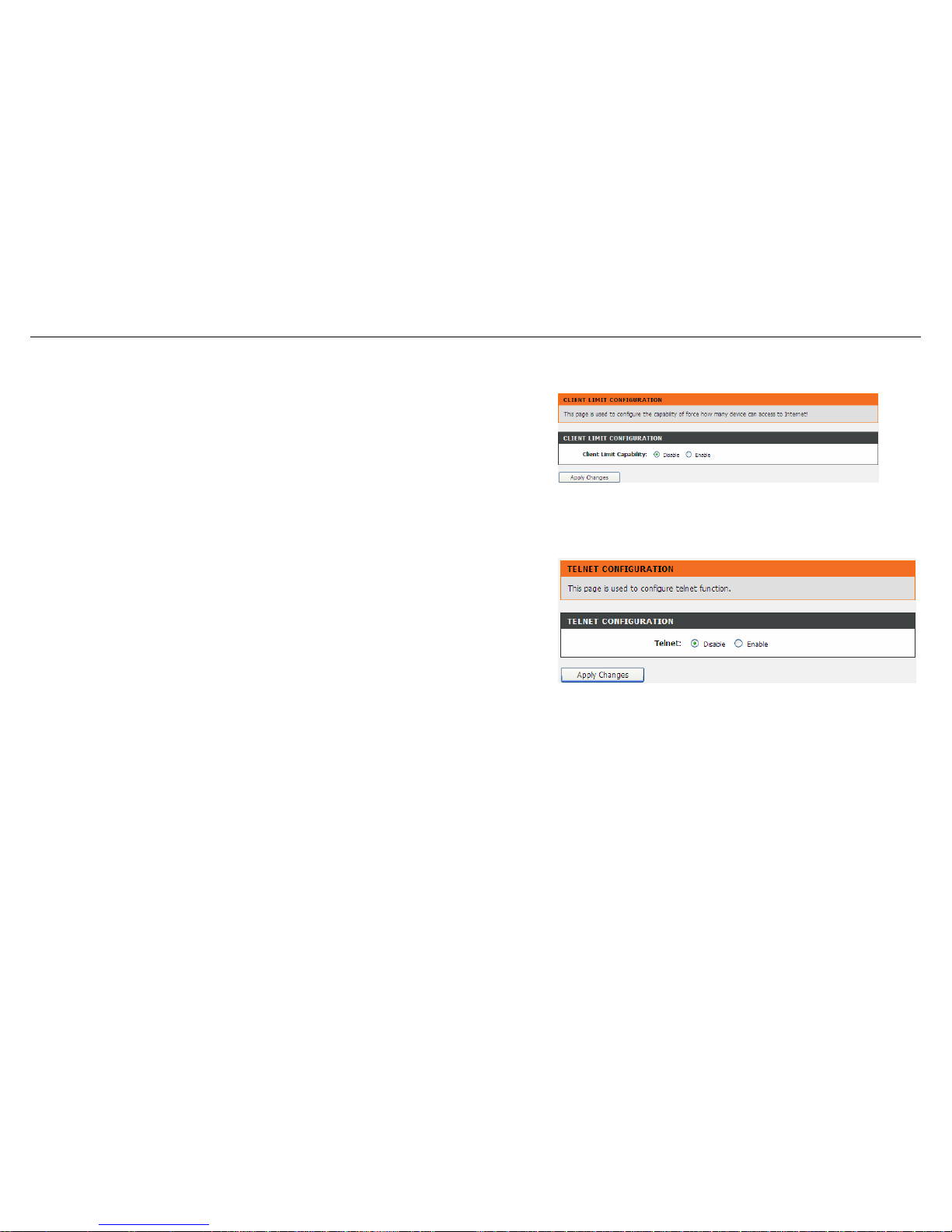
Choose Advanced > Network Tools > Client Limit. The Client Limit Configuration
page shown in the right figure appears. You may configure the capability of forcing
how many devices can access to the Internet.
Telnet
Choose Advanced > Network Tools > Telnet. The Telnet Configuration page
shown in the right figure appears. In this page, you can enable or disable telnet
function. After proper setting, click Apply Changes to take the setting into effect. After
enable telnet, you can log in to the router through telnet to manage the router.
62 D-Link DSL-526E User Manual
Page 63
Configuration
Routing
Under this menu, static route, IPv6 static route, and RIP type routing configurations can be performed.
Static Route
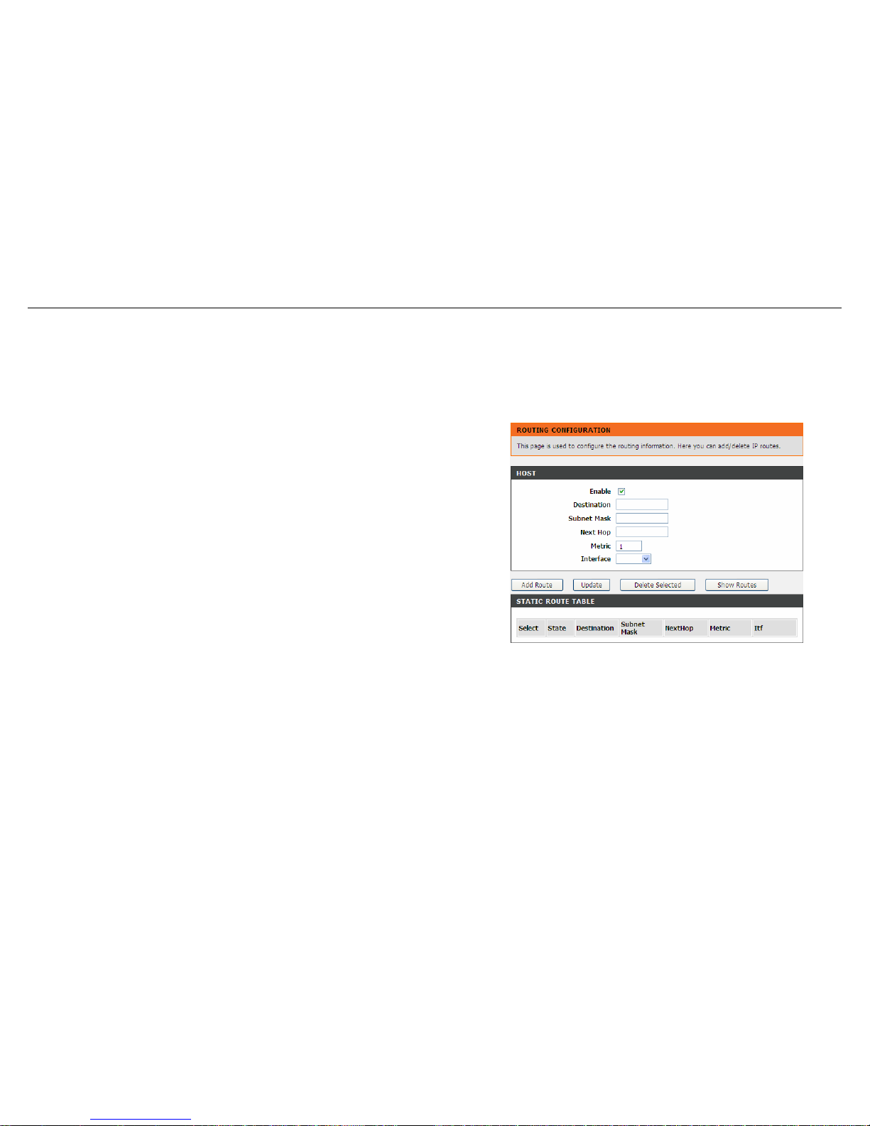
Choose Advanced > Routing > Static Route. The Routing Configuration page
shown in the right figure appears. This page is used to configure the routing
information. You may add or delete IP routes.
Configure the parameters in this page as described below.
Enable: Select it to use static IP routes.
Destination: Enter the IP address of the destination device.
Subnet Mask: Enter the subnet mask of the destination device.
Next Hop: Enter the IP address of the next hop in the IP route to the destination
device.
Metric: The metric cost for the destination.
Interface: The interface for the specified route.
Add Route: Click it to add the new static route to the Static Route Table.
Update: Select a row in the Static Route Table and modify the parameters. Then
click it to save the settings temporarily.
Delete Selected: Select a row in the Static Route Table and click it to delete the row.
Show Routes: Click it, the IP Route Table appears. You can view a list of destination
routes commonly accessed by your network.
Static Route Table: A list of the previously configured static IP routes.
63 D-Link DSL-526E User Manual
Page 64
Configuration
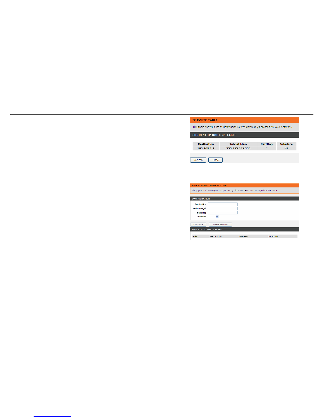
Click Show Routes, the page shown in the right figure appears. The table shows a
list of destination routes commonly accessed by your network.
IPv6 Static Route
Choose Advanced > Routing > IPv6 Static Route. The IPv6 Routing
Configuration page shown in the right figure appears. This page is used to configure
the routing information. You can add or delete IP routes.
Configure the parameters in this page as described below.
Destination: Enter the IPv6 address of the destination device.
Prefix Length: Enter the prefix length of the IPv6 address.
Next Hop: Enter the IP address of the next hop in the IPv6 route to the destination
address.
Interface: The interface for the specified route.
Add Route: Click it to add the new static route to the IPv6 Static Route Table.
Delete Selected: Select a row in the IPv6 Static Route Table and click it to delete
the row.
64 D-Link DSL-526E User Manual
Page 65
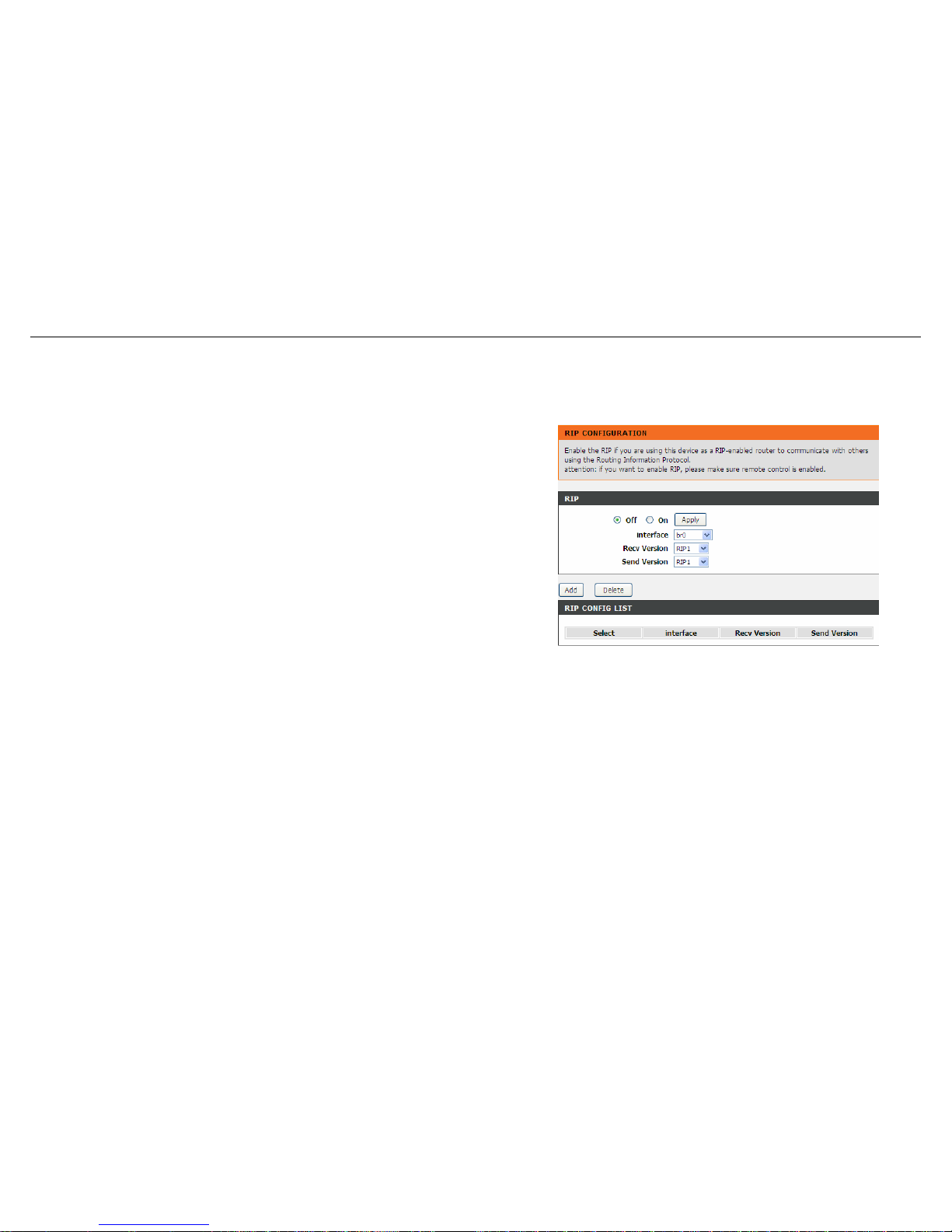
Configuration
RIP
Enable this function if you are using this device as a RIP-enabled router to communicate with others using Routing Information Protocol (RIP). This
page is used to select the interfaces on your devices that use RIP, and the version of the protocol used.
Choose Advanced > Routing > IPv6 Static Route. The IPv6 Routing
Configuration page shown in the right figure appears.
Configure the parameters in this page as described below.
RIP: Select Enable, the router communicates with other RIP-enabled devices.
Apply: Click it to save the settings of this page.
Interface: Choose the router interface that uses RIP.
Receive Version: Choose the interface version that receives RIP messages. You can
choose RIP1, RIP2, or Both.
Choose RIP1 indicates the router receives RIP v1 messages.
Choose RIP2 indicates the router receives RIP v2 messages.
Choose Both indicates the router receives RIP v1 and RIP v2 messages.
Send Version: The working mode for sending RIP messages. You can choose RIP1
or RIP2.
Choose RIP1 indicates the router broadcasts RIP1 messages only.
Choose RIP2 indicates the router multicasts RIP2 messages only.
Add: Click it to add the RIP interface to the Rip Config List.
Delete: Select a row in the Rip Config List and click it to delete the row.
D-Link DSL-526E User Manual 65
Page 66
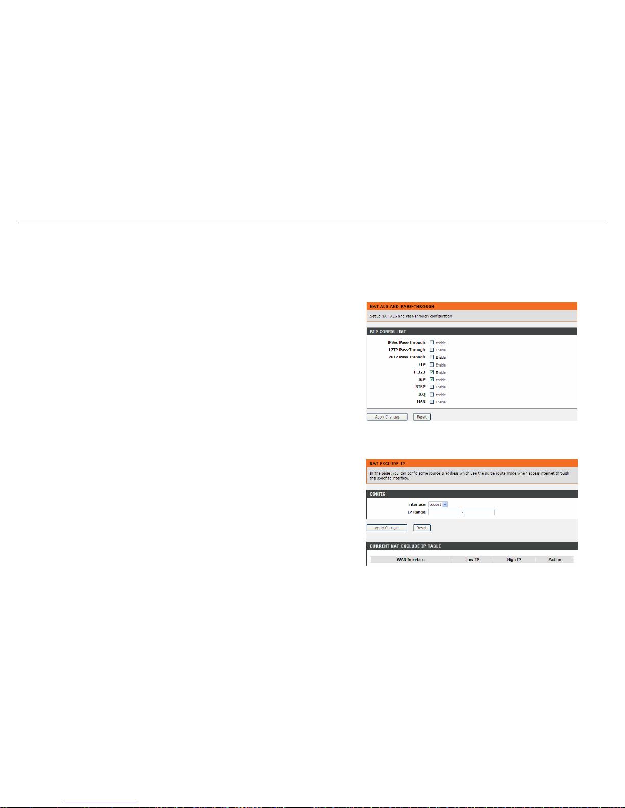
Configuration
NAT
Under this menu, NAT ALG (Application Layer Gateway), NAT Exclude IP, NAT Forwarding, FTP ALG Config and NAT IP Mapping can be performed.
NAT ALG
Choose Advanced > NAT > NAT ALG. The NAT ALG and Pass-Through page
shown in the right figure appears. Choose the NAT ALG and Pass-Through options,
and then click Apply Changes.
NAT Exclude IP
Choose Advanced > NAT > NAT Exclude IP. The NAT EXCLUDE IP page shown in
the right figure appears. In the page, you can configure some source IP addresses
which use the purge route mode when accessing the Internet through the specified
interface.
66 D-Link DSL-526E User Manual
Page 67
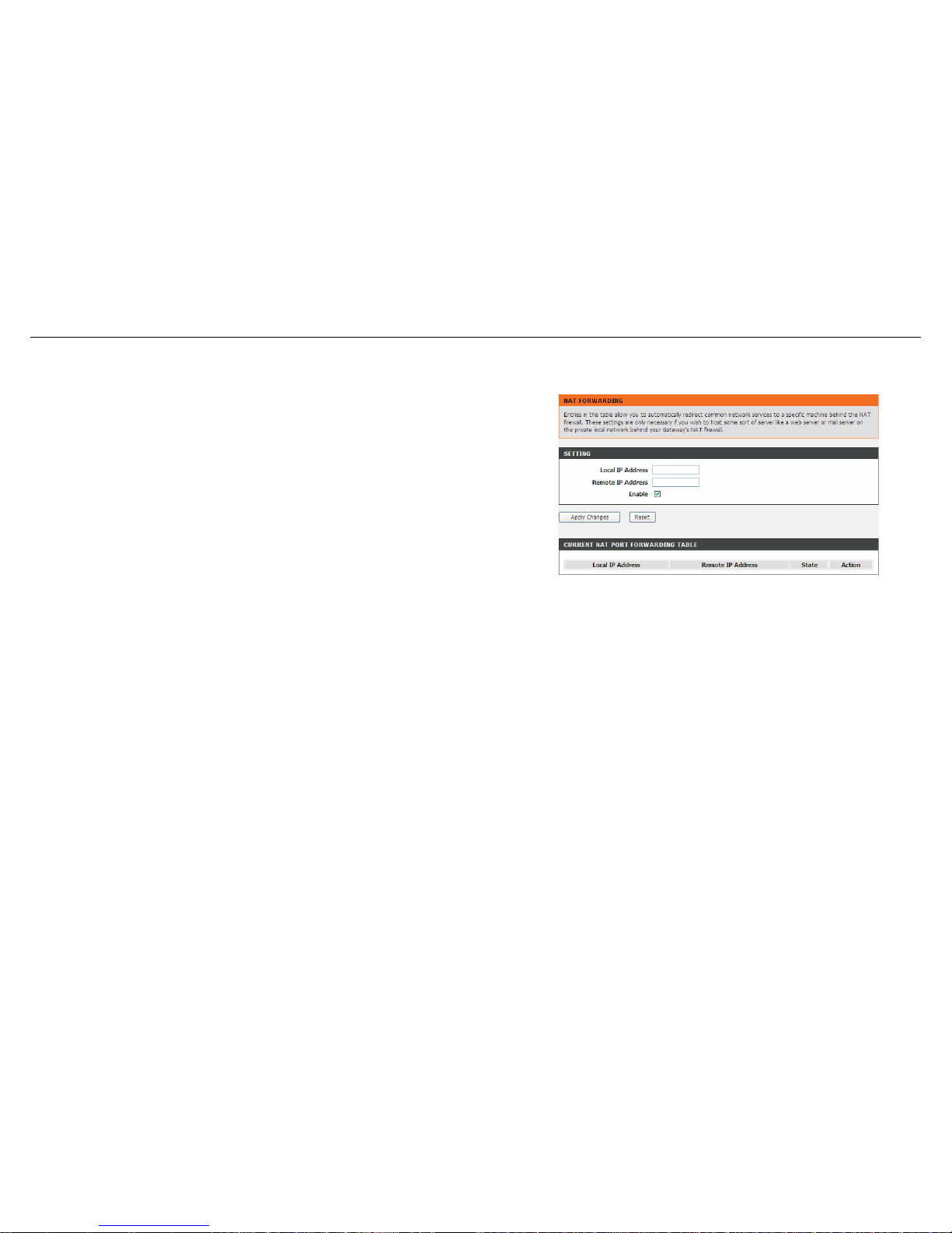
Configuration
NAT Forwarding
Choose Advanced > NAT > NAT Forwarding. The NAT Forwarding page shown in
the right figure appears.
Entries in this table allow you to automatically redirect common network services to a
specific machine behind the NAT firewall. These settings are only necessary if you
wish to host some sort of server like a web server or mail server on the private local
network behind your Gateway's NAT firewall.
Under 1483MER or 1483Routed mode, if NAPT (Network Address Port Translation) is
enabled, the Local IP Address is configured as 192.168.1.3 and the Remote IP
Address is configured as 202.32.0.2, the PC with the LAN IP192.168.1.3 will use
202.32.0.2 when it is connected to the Internet via the router without NAPT control.
Configure the parameters in this page as described below.
Local IP Address: Input a local IP address.
Remote IP Address: Input a remote IP address.
Enable: Enable the current configured rule.
Apply Changes: Submit the configurations.
Reset: Cancel the modification and reconfigure the settings.
Current NAT Port Forwarding Table: Current configuration rule list.
FTP ALG Config
The common port for FTP connection is port 21, and a common ALG monitors the TCP port 21 to ensure NAT pass-through of FTP. By enabling this
function, when the FTP server connection port is not a port 21, the FTP ALG module will be informed to monitor other TCP ports to ensure NAT
D-Link DSL-526E User Manual 67
Page 68
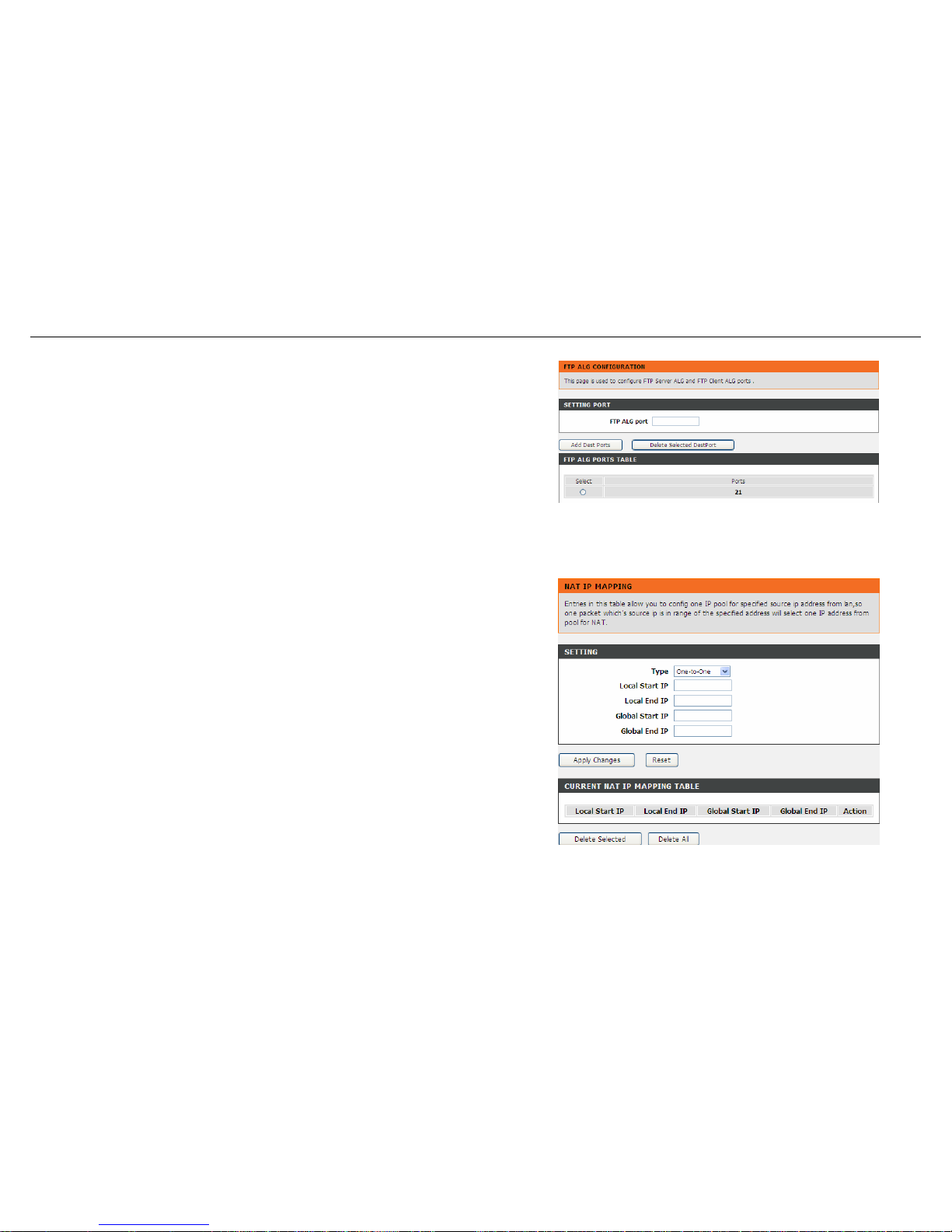
Configuration
pass-through of FTP.
Choose Advanced > NAT > FTP ALG Config. The FTP ALG Configuration page
shown in the right figure appears.
Configure the parameters in this page as described below.
FTP ALG port: Set an FTP ALG port.
Add Dest Ports: Add a port configuration.
Delete Selected DestPort: Delete a selected port configuration from the list.
NAT IP Mapping
Choose Advanced > NAT > NAT IP Mapping. The NAT IP Mapping page shown in
the right figure appears.
Entries in the Current NAT IP Mapping Table allow you to configure one IP pool for a
specified source IP address from LAN, so one packet whose source IP is in range of
the specified address will select one IP address from the pool for NAT.
68 D-Link DSL-526E User Manual
Page 69
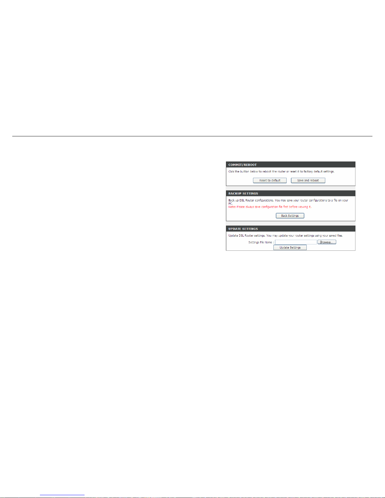
Configuration
Maintenance
System
Choose Maintenance > System. The page shown in the right figure appears. In this
page you can reboot your router or save your router configuration to a file on your
computer in case you have to reset your router to factory default settings. You can
restore your router settings from a previously saved configuration file.
You may also reset your router to factory default settings. Resetting your router to
factory default settings will delete your current configuration.
Configure the parameters in this page as described below.
Reset to default: This option restores all configuration settings back to the settings
that were in effect at the time the router was shipped from the factory. All settings will
be lost. If you want to save your router configuration settings, use the Backup
Settings option below.
Save and reboot: This will save all your settings and restart the router.
Back settings: Save your configurations in a file on your computer so that it may be
accessed again later if your current settings are changed. Be sure to save the
configuration before performing a firmware update.
Update settings: Click Browse to select the configuration file of device and click
Update Settings to begin restoring the device configuration.
Note: Do not turn off your device or press the Reset button while an operation in this page is in
progress.
D-Link DSL-526E User Manual 69
Page 70
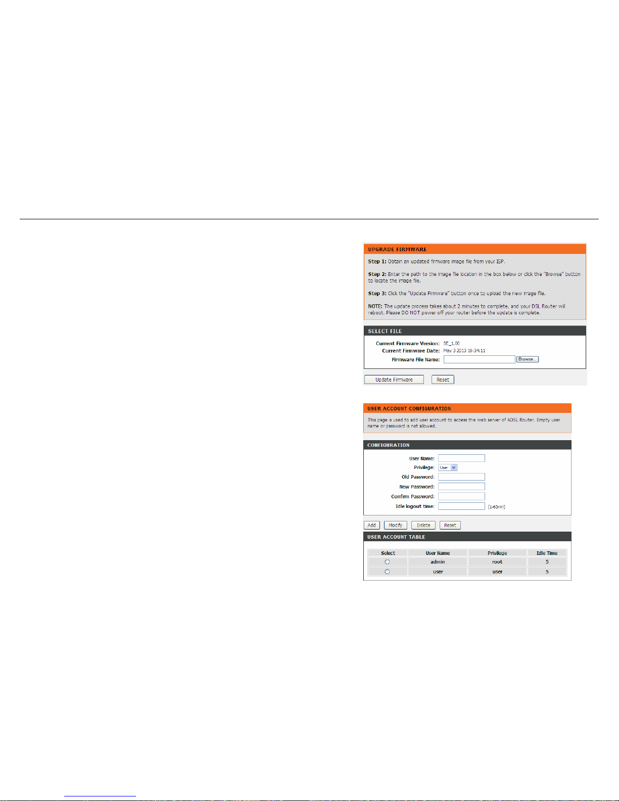
Configuration
Firmware Update
Choose Maintenance > Firmware Update. The page shown in the right figure
appears. This page displays your device firmware version and information that will be
helpful for D-Link technicians in case you require any technical support.
The procedure for updating the firmware is as follows.
Step 1 Click Browse…to search the file.
Step 2 Click Update Firmware to update the configuration file.
Step 3 Wait for the router to reboot. This can take another minute or more.
70 D-Link DSL-526E User anual M
Note: Some firmware updates reset the configuration options to the factory defaults.
Before performing an update, be sure to save the current configuration. Refer to the
section of System.
Password
Choose Maintenance > Password. The page shown in the right figure appears. You
may modify your router password needed to access this Web management interface.
For security reasons, it is recommended that you change the default admin and user
passwords of the router. The password you choose should be between 1 and 16
characters in length. If you forget your device password, the only solution is to reset
your router to factory default settings and you will lose all your device configuration
settings.
Configure the parameters in this page as described below.
Root: The root account is fixed, having full access to the Web-based management
interface.
User: The user account has the privilege to view configuration settings and statistics
and update the router's firmware.
Page 71
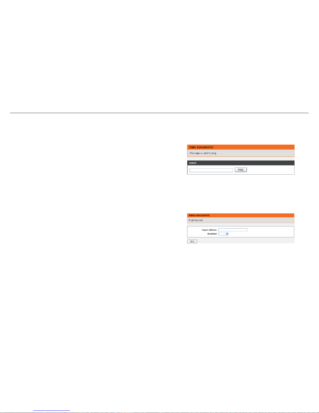
Configuration
Diagnostics
Ping
Choose Maintenance > Diagnostics > Ping. The page shown in the right figure
appears. This page allows you to ping a Host to test whether your router can be
connected to the network.
Configure the parameters in this page as described below.
Host: Enter the valid IP address or domain name.
Ping: Click it to start to Ping.
Ping6
Choose Maintenance > Diagnostics > Ping6. The page shown in the right figure
appears. The target Address can be a domain or IPv6 address.
Configure the parameters in this page as described below.
Target Address: Enter an IP address for Ping6 diagnosis.
Interface: Enter an interface through which the Ping6 diagnosis is performed.
D-Link DSL-526E User Manual 71
Page 72
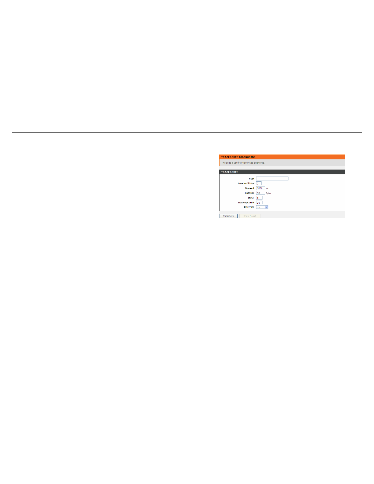
Configuration
Traceroute
Choose Maintenance > Diagnostics > Traceroute. The page shown in the right
figure appears. You can track the route path through the information which is from
your computer to the other side host on the Internet.
Configure the parameters in this page as described below.
Host: Enter the destination host address for diagnosis.
NumberOfTries: Number of repetitions.
Timeout: Put in the timeout value.
Datasize: Packet size.
DSCP: Differentiated Services Code Point, You should set a value between 0-63.
MaxHopCount: Maximum number of routes.
Interface: Select the interface.
Traceroute: Click it to start traceroute.
72 D-Link DSL-526E User Manual
Page 73
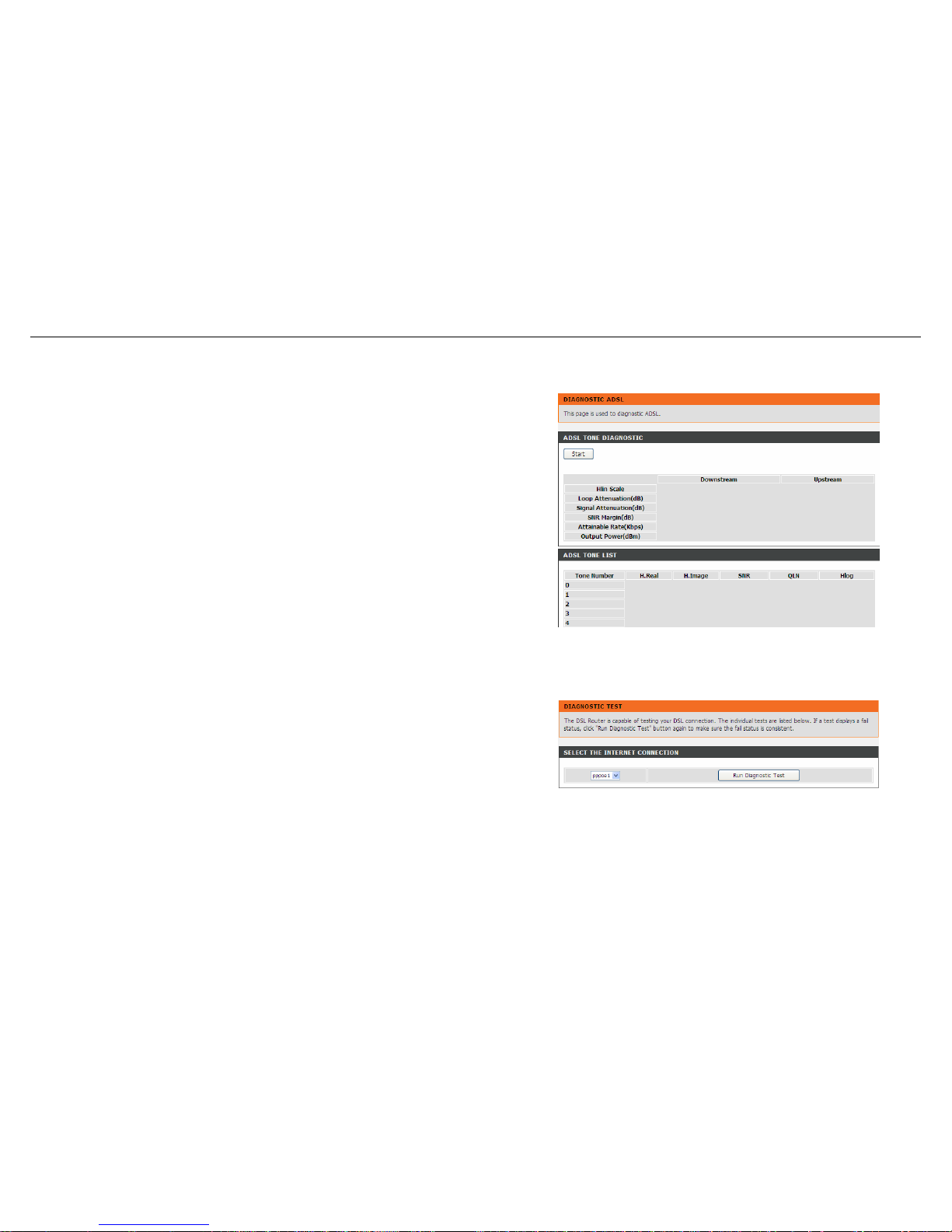
Configuration
ADSL
Choose Maintenance > Diagnostics > ADSL. The page shown in the right figure
appears. It is used for ADSL tone diagnostics.
Click Start to start ADSL tone diagnostics.
Diag Test
Choose Maintenance > Diagnostics > Diag Test. The page shown in the right figure
appears. In this page, you can test the DSL connection. You can also view the LAN
status connection and ADSL connection.
D-Link DSL-526E User Manual 73
Page 74
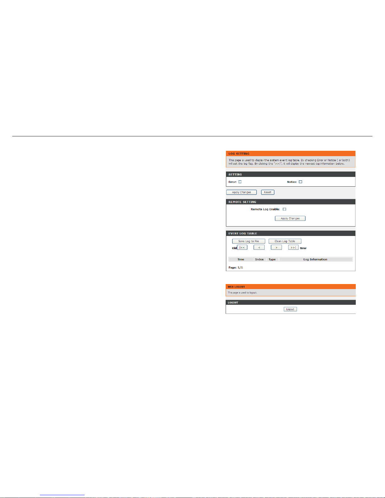
Configuration
System Log
Choose Maintenance > System Log. The page shown in the right figure appears.
This section when enabled allows the system to begin logging events based on the
selected log level.
The router can only keep a limited number of log entries due to router memory
constraints. If you have an external SYSLOG server, you may choose to configure
external logging and all log entries will be sent to your remote server.
Configure the parameters in this page as described below.
Error: When the system is likely to result in a module abnormity, the system
generates an Error log.
Notice: When the system is under attack or logged in, or port status changes, the
system generates a Notice log.
Remote Log Enable: Send system log to remote host, maybe a domain or an IP.
Save Log to File: You can save current log table to a file.
Logout
Choose Maintenance > Logout. The page shown in the right figure appears. In this
page, you can log out of the configuration page.
74 D-Link DSL-526E User Manual
Page 75
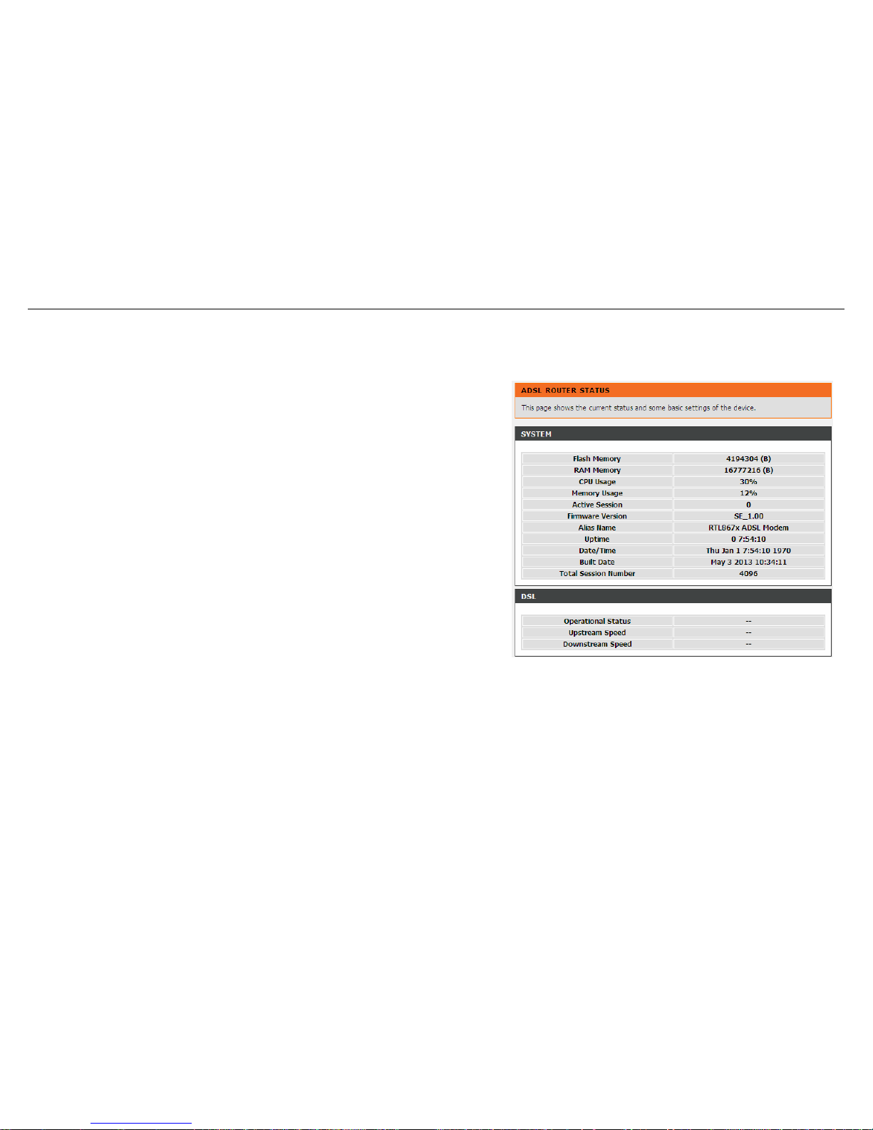
Configuration
Status
You can view the system information and monitor performance.
Device Information
Choose Status > Device Info. The page shown in the right figure appears. This page
displays a summary overview of your router, including system information, DSL
information, LAN Configuration, DNS information, WAN Configuration and so on.
D-Link DSL-526E User Manual 75
Page 76
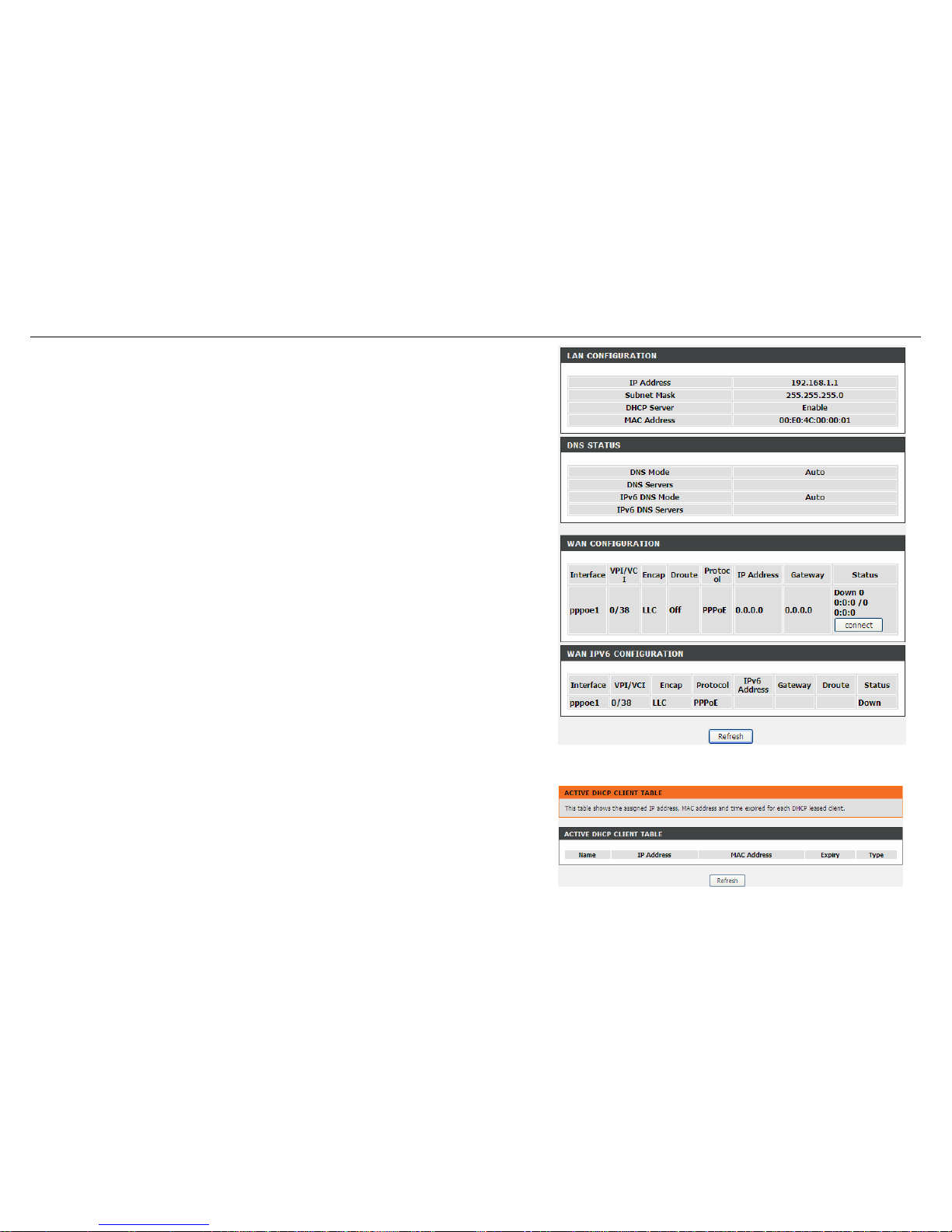
Configuration
DHCP Clients
Choose Status > DHCP Clients. The page shown in the right page appears. This
page displays all client devices that obtain IP addresses from the device. You can
view the host name, IP address, MAC address and time expired(s).
76 D-Link DSL-526E User Manual
Page 77
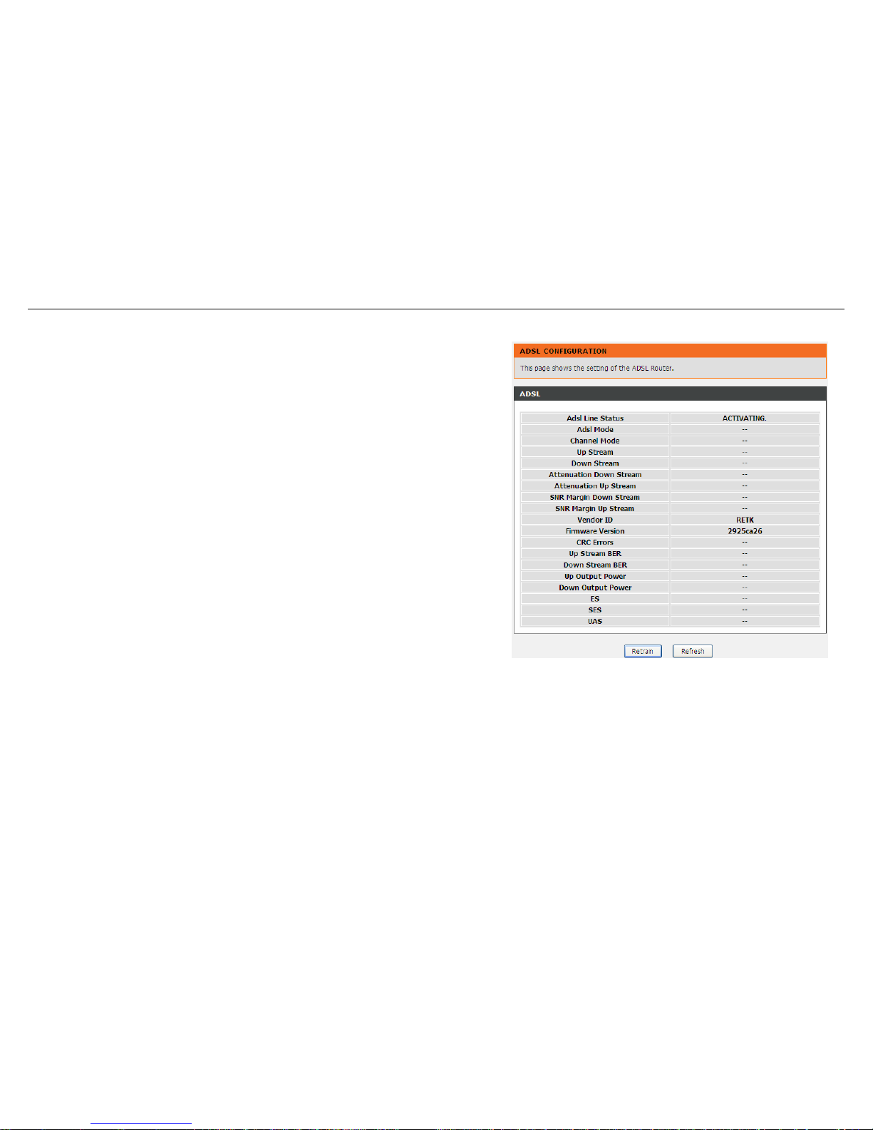
Configuration
ADSL Driver
Choose Status > ADSL Driver. The page shown in the right page appears. This
page displays all ADSL statistics information, including link down or on, downstream
and upstream, type, line coding and so on.
D-Link DSL-526E User Manual 77
Page 78
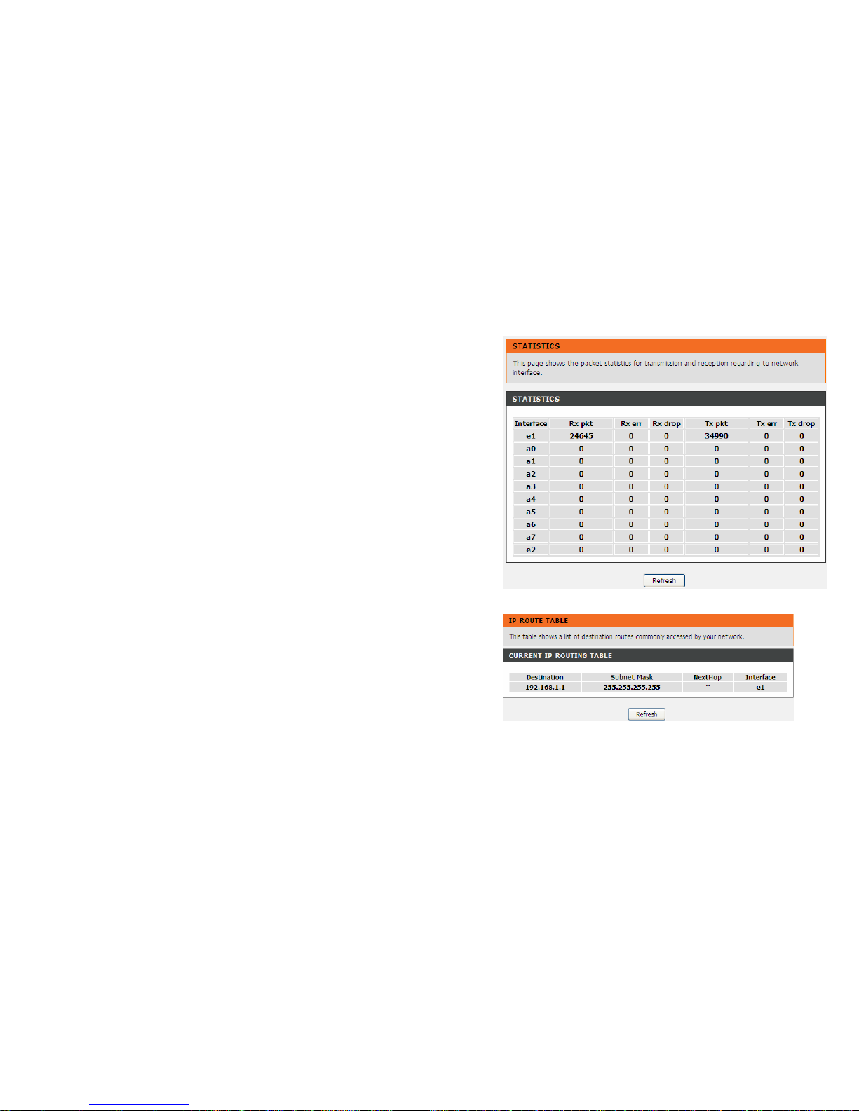
Configuration
Statistics
Choose Status > Statistics. The page shown in the right page appears. This is a
summary of the number of packets that have passed between the WAN and the LAN
since the router was last initialized.
Route Information
Choose Status > Route Info. The page shown in the right page appears. This table
shows a list of destination routes commonly accessed by your network.
78 D-Link DSL-526E User Manual
Page 79
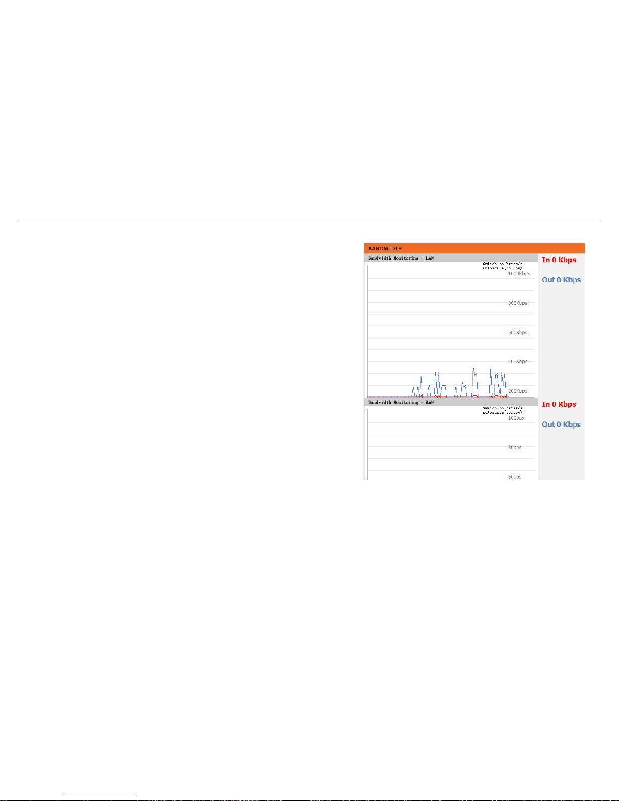
Configuration
Traffic Graphic
Choose Status > Traffic Graphic. The page shown in the right page appears. In this
page, you can view bandwidth monitoring graphic.
D-Link DSL-526E User Manual 79
Page 80
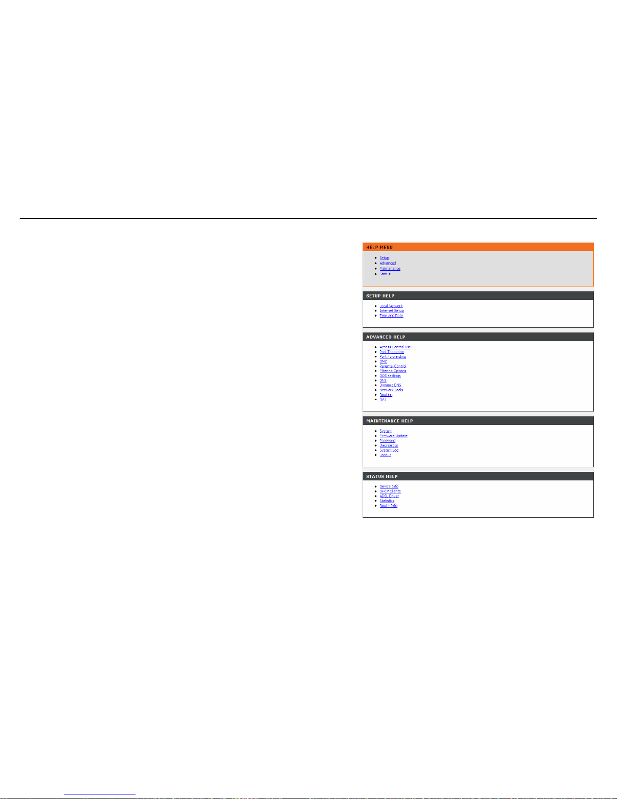
Configuration
Help
In the main interface, click Help tab to enter the Help menu as shown in the right
figure. This section provides detailed configuration information for the device. Click a
link to view corresponding information.
80 D-Link DSL-526E User Manual
Page 81

Troubleshooting
81 D-Link DSL-526E User Manual
Troubleshooting
This chapter provides solutions to problems that might occur during the installation and operation of the DSL-526E. Read the following descriptions
if you are having problems. (The examples below are illustrated in Windows® XP. If you have a different operating system, the screenshots on your
computer will look similar to the following examples.)
1. How to configure the DSL-526E Modem Router without the CD-ROM?
Connect your PC to the Router using an Ethernet cable.
Open a web browser and enter the address http://192.168.1.1
The default username is ‘admin’ and the default password is ‘admin’.
If you have changed the password and cannot remember it, you will need to reset the Router to the factory default setting (see question 2),
which will set the password back to ‘admin’.
Note:
Please refer to the next section “Networking Basics” to check your PC’s IP configuration if you can’t see the login windows.
2. How to restore the Router to the factory default settings?
Ensure the Router is powered on.
Press and hold the reset button on the back of the device for approximately 3 seconds.
This process should take around 1 to 2 minutes.
Note:
Resetting the Router to the factory default settings will erase the current configuration settings. To reconfigure your settings, login to the Router as
outlined
in
question 1, and then run the Wizard.
3. What to do if the Router does not work normally?
There are a few quick steps you can take to try and resolve any issues:
Follow the directions in Question 2 to reset the Router.
Check that all the cables are firmly connected at both ends.
Check the LEDs on the front of the Router. The Power indicator should be on, the Status indicator should flash, and the DSL and LAN
indicators should be on as well.
Please ensure that the settings in the Web-based configuration manager, e.g. ISP username and password, are the same as the settings
that have been provided by your ISP.
Page 82

Configuration
82 D-Link DSL-526E User Manual
4. Why the Internet connection cannot be established?
For ADSL ISP users, please contact your ISP to make sure the service has been enabled/connected by your ISP and that your ISP username and
password are correct.
5. What to do if the Router can’t be detected by running the installation CD?
Ensure the Router is powered on.
Check that all the cables are firmly connected at both ends and all LEDs are working correctly.
Ensure only one network interface card on your PC is activated.
Click on Start > Control Panel > Security Center to disable the firewall.
Note:
There is a potential security issue if the firewall is disabled on your PC. Please remember to turn it back on once you have finished the whole
installation
procedure. This will enable you to surf the Internet without any problems.
Page 83
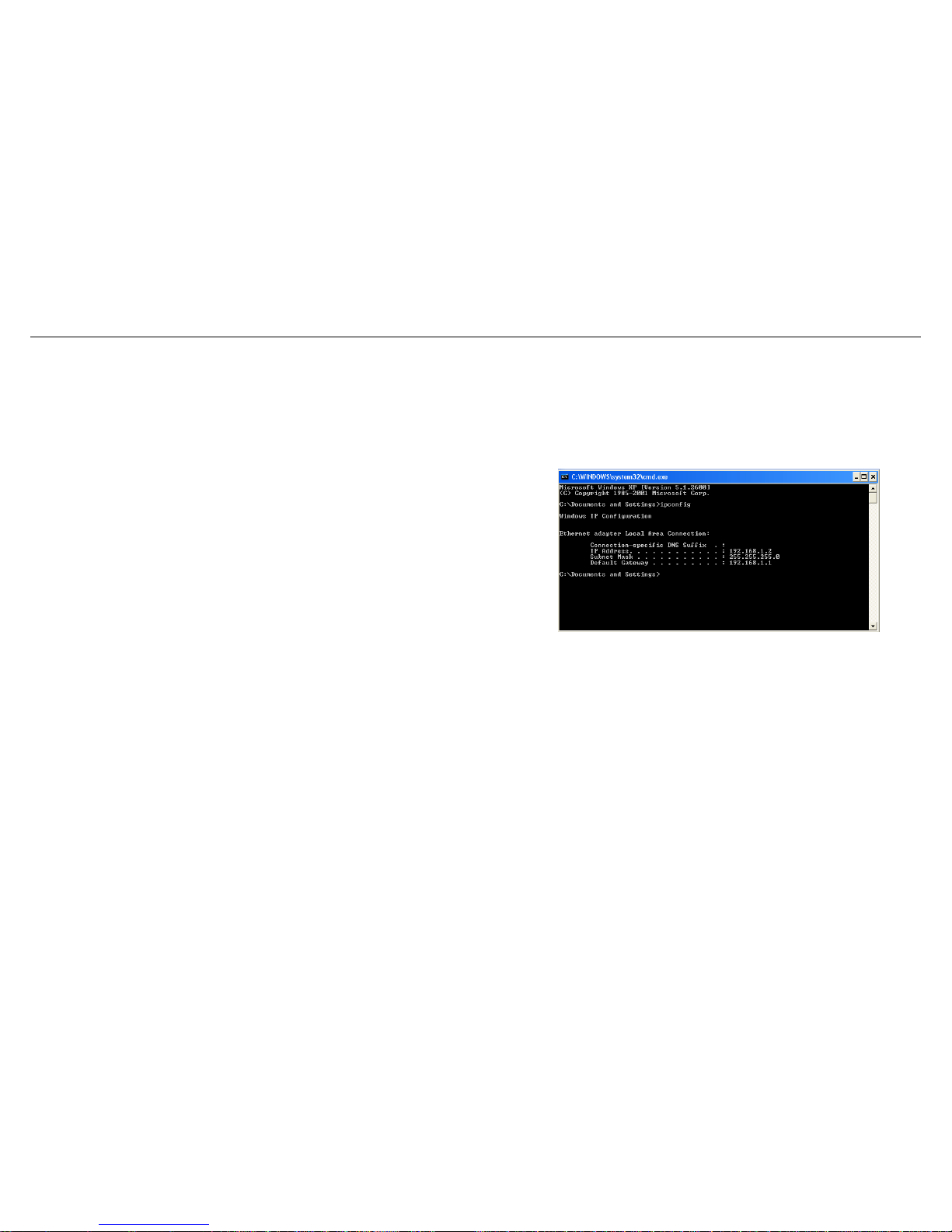
Networking Basics
Networking Basics
Check Your IP Address
After you install your new D-Link adapter, by default, the TCP/IP settings should be set to obtain an IP address from a DHCP server (i.e. wireless
router) automatically. To verify your IP address, please follow the steps below.
Click on Start Run. In the run box type cmd and click on the OK button.
At the prompt, type ipconfig and press Enter.
This will display the IP address, subnet mask and the default gateway of your
adapter.
If the address is 0.0.0.0, check your adapter installation, security settings and the
settings on your router. Some firewall software programs may block a DHCP request
on newly installed adapters.
If you are connecting to a wireless network at a hotspot (e.g. hotel, coffee shop,
airport), please contact an employee or administrator to verify their wireless network
settings.
83 D-Link DSL-526E User Manual
Page 84
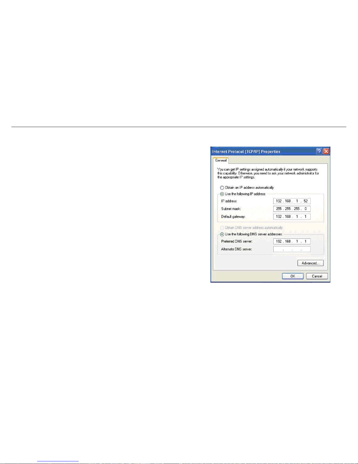
Configuration
Statically Assigning an IP Address
If you are not using a DHCP capable gateway/router, or you need to assign a static IP address, please follow the steps below:
Step 1
Windows® XP - Click on Start > Control Panel > Network Connections.
Windows® 2000 - From the desktop, right-click on the My Network Places >
Properties.
Step 2
Right-click on the Local Area Connection which represents your network adapter
and select the Properties button.
Step 3
Highlight Internet Protocol (TCP/IP) and click on the Properties button.
Step 4
Click on the Use the following IP address and enter an IP address that is on the
same subnet as your network or the LAN IP address on your router.
Example: If the router’s LAN IP address is 192.168.1.1, make your IP address
192.168.1.X where X is a number between 2 and 254. Make sure that the number
you choose is not in use on the network. Set the Default Gateway to be the same as
the LAN IP address of your router (192.168.1.1).
Set the Primary DNS to be the same as the LAN IP address of your router
(192.168.1.1). The Secondary DNS is not needed or you may enter a DNS server
from your ISP.
Step 5
Click on the OK button twice to save your settings.
84 D-Link DSL-526E User Manual
Page 85

Technical Specifications
Technical Specifications
ADSL Standards
Data Transfer Rate
G.dmt full rate downstream: up to 8 Mbps / upstream:
up to 1 Mbps
ANSI T1.413 Issue 2
ITU G.992.1 (G.dmt) AnnexA
G.lite: ADSL downstream up to 1.5 Mbps / upstream
up to 512 Kbps
ITU G.992.2 (G.lite) Annex A
ITU G.994.1 (G.hs)
G.dmt.bis full rate downstream: up to 12 Mbps /
upstream: up to 12 Mbps
ITU G.992.5 Annex A
ADSL full rate downstream: up to 24 Mbps / upstream:
up to 1 Mbps
ADSL2 Standards
ITU G.992.3 (G.dmt.bis) Annex A
Media Interface
ITU G.992.4 (G.lite.bis) Annex A
ADSL interface: RJ-11 connector for connection to
24/26 AWG twisted pair telephone line
ADSL2 Standards
LAN interface: RJ-45 port for 10/100BASE-T Ethernet
connection
ITU G.992.5 (ADSL2+)
USB interface for standard USB connection
Protocols
IEEE 802.1d Spanning Tree
RFC1483/2684 Multiprotocol
Encapsulation over ATM
Adaptation Layer 5 (AAL5)
TCP/UDP
ARP
RFC1661 Point to Point Protocol
ICMP
RFC1994 CHAP
RFC1058 RIP v1
RFC2131 DHCP Client / DHCP
Server
RFC1213 SNMP v1 & v2c
RFC1334 PAP
RFC2364 PPP over ATM
RFC1389 RIP v2
RFC2516 PPP over Ethernet
FC1577 Classical IP over
ATM
85 D-Link DSL-526E User Manual
 Loading...