

Page 1
DKVM-2/4
2/4-
Port Keyboard, Video,
and Mouse Switch
Manual
Rev. 1.2
Page 2

II
Contents
Introduction..............................................................................1
Hardware Installation...............................................................2
Front Panel Layout.....................................................................................2
Rear Panel Layout.....................................................................................2
Using the DKVM-2/4................................................................6
“Select” button............................................................................................6
Keyboard “Hot Key commands................................................................7
Optional cable.............................................................................................7
Troubleshooting.......................................................................8
Keyboard.....................................................................................................8
Mouse ..........................................................................................................8
Video..........................................................................................................10
Product Features.....................................................................1
Specifications........................................................................11
FCC Certifications................................................................12
D-Link Offices........................................................................13
Technical Support........................................................15
Warranty......................................................................16
Registration.................................................................20
Page 3

Introduction
Thank you for purchasing the DKVM-2/4 KVM Switch. This product will
ensure easy and accurate control over 2 or 4 PCs through a single
console. The DKVM-2/4 is compatible with mice and keyboard with
PS/2 type connectors. Older style keyboards or mice can be used with
PS/2 adapters in the case that the device is PS/2 compatible. Most
older style serial keyboard and mice are not compatible with PS/2.
Advanced features like keyboard and mouse emulation for error free
boot-ups and support is also provided for the Microsoft Intellimouse
and Microsoft Intellimouse Explorer.
The DKVM -2/4 supports high resolutions. Resolutions up to 1920 x
1440 are supported with no deterioration of image quality.
Switching between PCs can be accomplished in two ways: through
keyboard “Hot Key” commands or by using the convenient front-panel
“Select” pushbu tton controls.
Product Features
§ Allows a user to control 2/4 computers from one console.
§ Works with DOS, Windows, OS/2, UNIX, Linux etc.
§ No drivers or other additional software required.
§ Keyboard and mouse emulation allows error-free boot -up.
§ The status of the CAPS LOCK, SCROLL LOCK and NUM
LOCK keys is preserved for each of the computers.
§ Uses inexpensive and commonly available cables. Molded KVM
cables are recommended. Model No. DKVM-CB
§ Supports Monitor resolutions of up to 1920 x 1440.
§ Supports VGA, SVGA and Multisync monitors.
§ “Select” push -button or keyboard “Hot Key” control.
§ Comes with Auto-Scan mode for convenient automatic
switching.
§ Front panel status LEDs give a clear indication of the active PC.
§ Audible feedback when switching between computers.
Page 4
Package Contents
In addition to this User’s Guide, please check that you have the
following contents of this package…
§ DKVM-2/4
§ Power Adapter
Hardware Installation
This section will explain how to connect the console and the
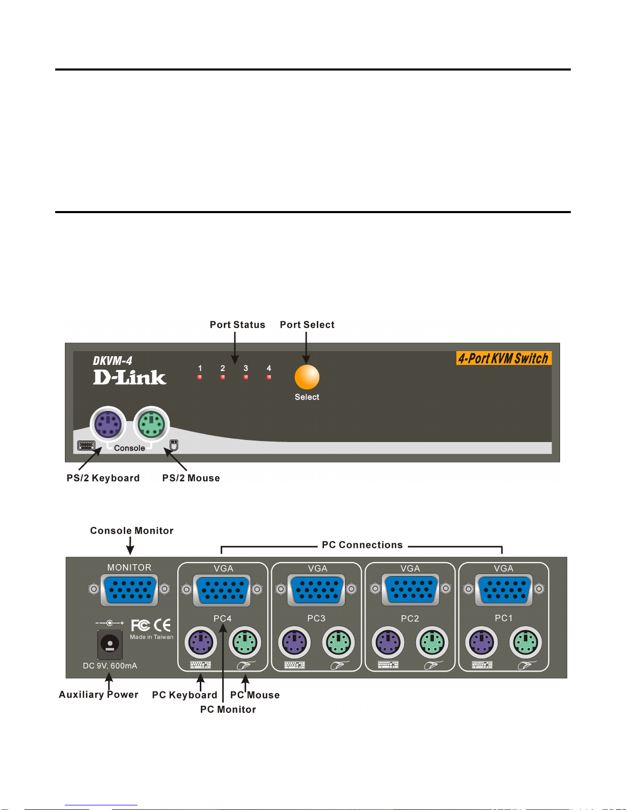
computers to the DKVM-4 swit ch unit. First the layout of front and rear
panel will be shown.
FRONT PANEL LAYOUT
REAR PANEL LAYOUT
Before you start connecting your computers and console devices to
the DKVM -2/4, please make sure that everything is powered off.
Page 5
Note: Please make sure the mouse you are planning to use is a 2
Button or 3 Button mouse, and that it is fully Microsoft
Mouse compatible. If your mouse driver is not Microsoft
mouse driver compatible, please do not uninstall your
mouse driver or the existing driver from the PC and then
install the Windows native mouse driver.
Please follow the steps below closely and in the order as shown,
otherwise, keyboard and/or mouse errors may occur.
Step 1. Place the DKVM -2/4 in a convenient location. Its small size
makes it easy to place on the desktop. Do take the length of
the cables in consideration when placing the KVM switch unit.
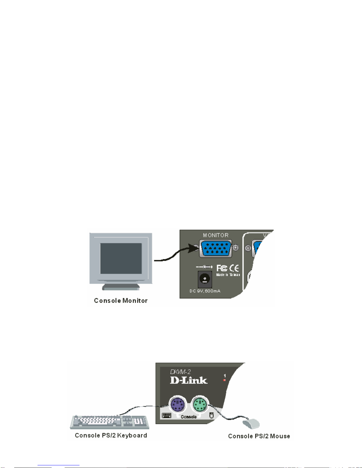
Step 2. We will now connect the console devices. Connect your
monitor to the DKVM -2/4. The 15-pin connector coming from
your monitor must be inserted into the unit on the rear panel.
Connect it to the 15 pin HDDB connector labeled
=MONITOR=.
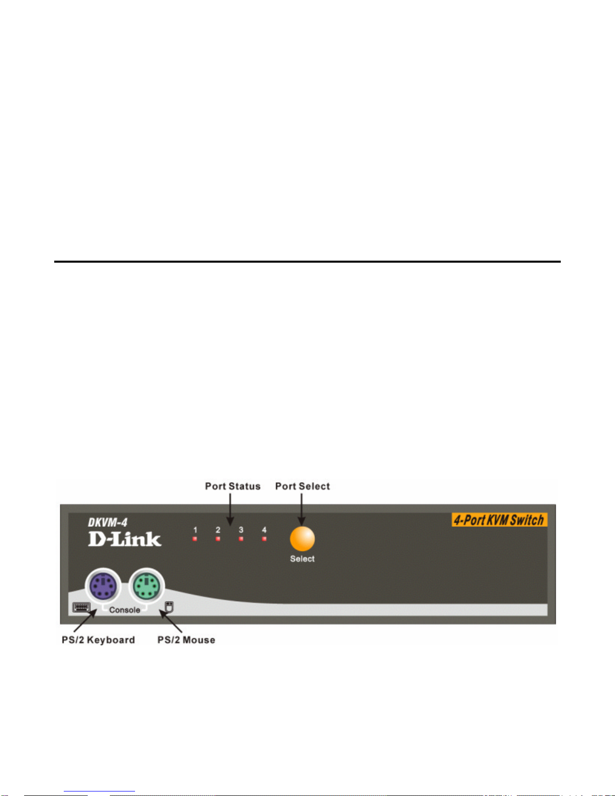
Step 3. Connect your PS/2 keyboard and PS/2 mouse to the front
panel of the DKVM-2/4. The connections should be made to
the two 6-pin Mini DIN connectors labeled =CONSOLE= as
shown below.
Page 6
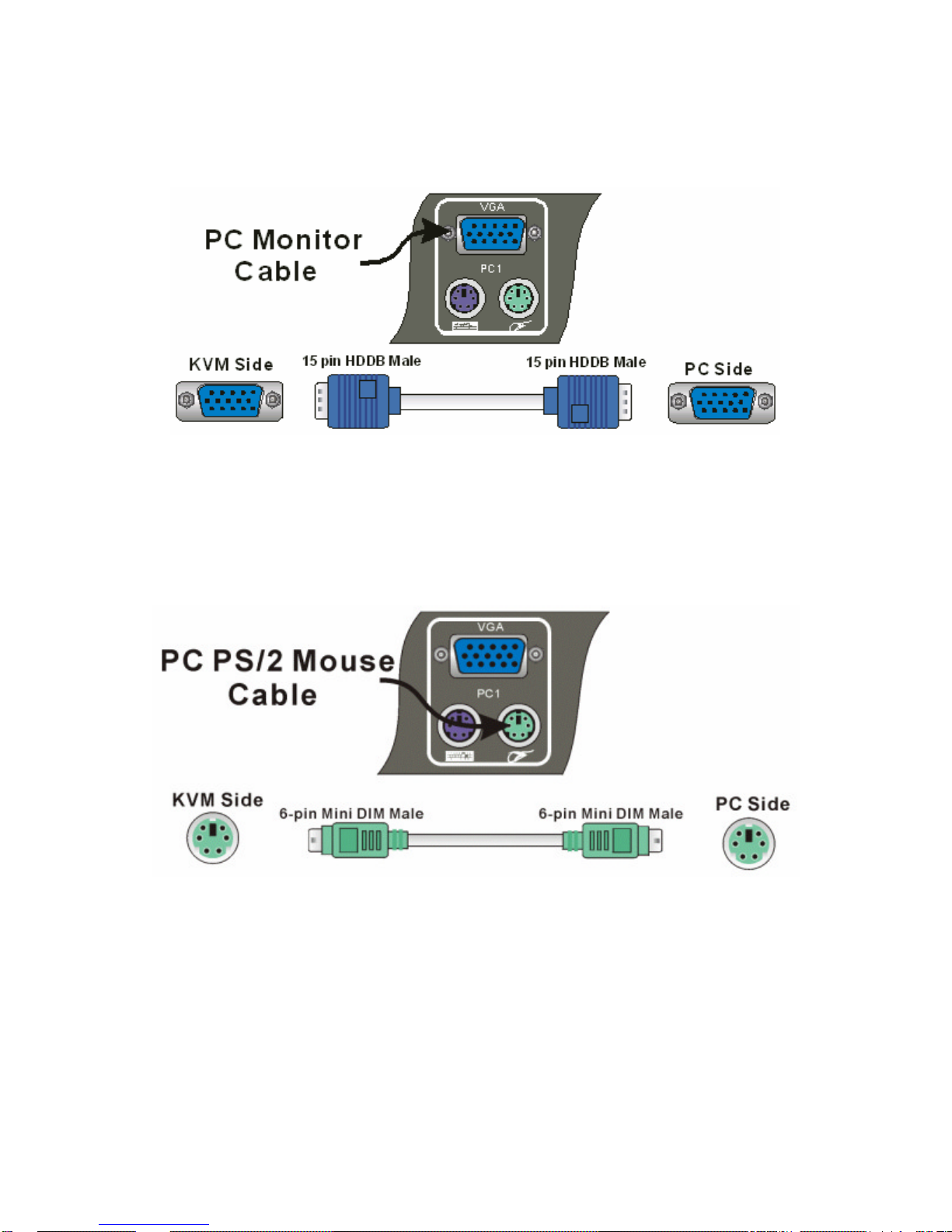
Step 4. Now the PC connections will be made with the monitor (VGA)
connections. Connect a VGA cable (15-pin HDDB Male /
Male) with the Male side to both the PC and to the connector
labeled VGA on the rear panel of the DKVM-2/4 unit. Repeat
this for all PCs.
Step 5. Now connect the PS/2 mouse cables from your computers to
the DKVM -2/4 unit. Connect a mouse cable (6-pin Mini DIN
Male / Male) to the PC and to the connector with the mouse
symbol on the rear panel of the DKVM-2/4 unit. Repeat this for
all PCs.
Step 6. To finish the hardware installation, connect the PS/2 keyboard
cables from your computers to the DKVM-2/4 unit. Connect a
keyboard cable (6-pin Mini DIN Male / Male) to the PC and to
Page 7
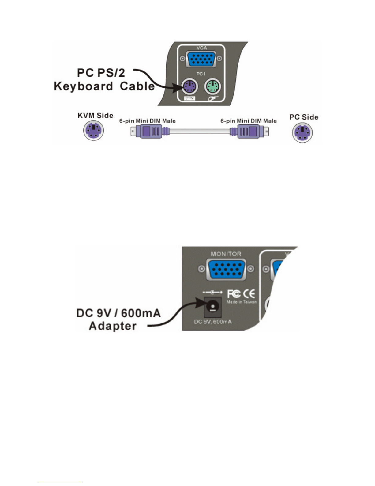
the connector with the keyboard symbol on the rear panel of
the DKVM -2/4 unit. Repeat this for all PCs.
Step 7. Now make sure to verify all cables. In particular, keyboard and
mouse cables should be checked because they are easily
switched and they use the same type of connector.
Step 8. Attach the power supply to the DKVM-2/4 unit and plug it into
a power outlet. You will see the LED for Port 1 light up, and
you will hear a beep. Switch on your monitor.
Step 9. Now power up all computers simultaneously. The first
computer that is connected to port PC1 will be shown on the
monitor. You may check to see if the mouse and keyboard
work after the system has booted up. If this is OK, use the
“Select” button to choose the next computer and verify the
functionality in the same way. If you find errors, re-check all
cables for proper connections before going to the
troubleshooting section of this manual.
Page 8
Note: Please do not switch the PC port (i.e. Do not press the push
button of KVM switch or run hot key) while the computers
are under their boot -up process.
Normally, during boot -up process, each PC will
communicate with the keyboard and mouse. If you switch
PC ports on the KVM at this moment, it will cause
communication errors or initialization failures between PC
and keyboard or mouse.
Using the DKVM-2/4
The DKVM -2/4 switch unit provides two ways to select which computer
is the active system. Use either the “Select” button on the unit, or
make use of the keyboard “Hot key” commands.
You may notice that the mouse cannot be used for around 2 seconds
when the DKVM -2/4 switches to another computer. This is normal and
is caused by synchronization that makes sure the mouse operates
properly.
“SELECT” BUTTON
Pressing the Select button cycles through computers 1 ~ 2/4
Page 9
KEYBOARD “HOT KEY COMMANDS
To send “Hot Key” commands to the DKVM-2/4 unit, press the
SCROLL LOCK Key twice within 2 seconds.
You will be given a beep as confirmation. Now press a command key
to give a “Hot Key” command. The following commands are supported:
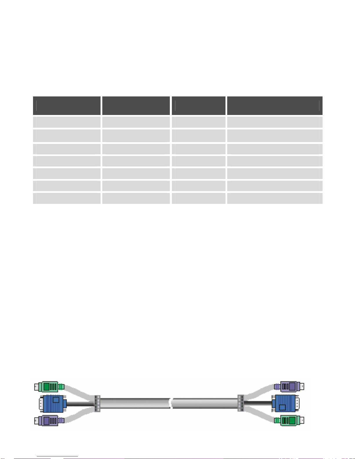
FIRST KEY SECOND KEY THIRD KEY COMMAND
SCROLL LOCK SCROLL LOCK 1 Switch to First PC
SCROLL LOCK
SCROLL LOCK
2 Switch to Second PC
SCROLL LOCK SCROLL LOCK 3 Switch to Third PC
SCROLL LOCK SCROLL LOCK 4 Switch to Fourth PC
SCROLL LOCK SCROLL LOCK ? Switch to Previous PC
SCROLL LOCK SCROLL LOCK ? Switch to Next PC
SCROLL LOCK SCROLL LOCK S Go to Auto Scan mode
In Auto-Scan mode, the DKVM -2/4 unit will switch to the next
computer every 10 seconds. This means that all computers will be
shown on the monitor in a row, starting with the first computer after the
last one has been shown.
In this mode, there is no mouse or keyboard control, which is needed
to prevent errors. Erratic input will result if a mouse move or keyboard
key press is given just as the unit switches to the next computer.
To exit Auto-Scan mode, press the SPACE BAR. The DKVM-2/4 will
stop at the last computer shown.
OPTIONAL CABLE
Model No. DKVM-CB 6 feet (180cm) 3-in-one Cable kit is available for
DKVM-2/4 KVM switch. Visit www.dlinkshop.com for details.
Page 10

Troubleshooting
KEYBOARD
My keyboard is not detected, or a keyboard error is given during
boot-up. What can be the cause?
Please verify that the keyboard cables are inserted properly.
The computers all boot up properly, but the keyboard is not
functional. What can be the cause?
One of the following may be the case:
§ Make sure the keyboard is plugged into the DKVM -2/4 unit
properly.
§ Verify that the keyboard works when plugged into the computer
directly. (You will have to shut down your computer first to do
this).
§ Try using a different keyboard.
§ Read your motherboard documentation and make sure that the
PS/2 keyboard IRQ is enabled. (This can be set for most
computers in the BIOS setup pages)
MOUSE
My mouse is not detected during boot up. What can be the
cause?
One of the following may be the case:
§ Please verify that all mouse cables are inserted properly. Check
especially for a mix-up with the PS/2 keyboard cable, they have
the same kind of connector and are therefore easily confused.
§ Read your motherboard documentation and make sure that the
PS/2 mouse IRQ is enabled. (This can be set for most
computers in the BIOS setup pages)
Page 11

The computers boot properly but I cannot use the mouse. What
can be the cause?
One of the following may be the case:
§ Please verify that the mouse is plugged into the DKVM-2/4 unit
properly.
§ Make sure the mouse works properly when plugged into a
computer directly. You will need to reboot the system to test
this.
§ Try using a different mouse.
§ Verify that the mouse complies with the PS/2 standard. A
combination mouse will work, but it must be set to PS/2 mode
and the correct serial mouse to PS/2 adapter must be used. A
serial mouse with a serial - PS/2 adapter will not work, since the
mouse signals do not comply with the PS/2 standard.
§ Make sure that the power adapter is plugged in at both ends
and that it is working correctly. Its rating must be 9V 600mA.
When I switch between computers, mouse movement becomes
random. What can be the cause?
One of the following may be the case:
§ Verify that your computers do not have more than one mouse
driver installed. Make sure that the driver is for a standard PS/2
or fully Microsoft compatible PS/2 mouse. Also check with the
mouse vendor to verify you are using the latest mouse driver.
§ Check your config.sys and autoexec.bat files (if you run
Windows that is) and verify that only one mouse driver is
loaded.
§ If a special mouse is used, such as a cordless or scrolling
mouse, make sure you use generic PS/2 mouse drivers. A non-
standard PS/2 mouse may have extensions on the PS/2
protocol that are not supported by the DKVM-2/4 unit.
§ Do not move the mouse or press any mouse buttons while
switching from one system to the other.
§ Try resetting the mouse by unplugging it from the DKVM-2/4
unit for about 3 seconds. Mouse movement will now be correct
again.
Page 12

§ Before booting up any PCs, the DKVM-2/4 unit must be
powered-up. But before powering the DKVM-2/4 unit up, the
mouse and keyboard must be connected. Any deviation from
this power-up sequence may lead to erratic behavior of the
systems.
VIDEO
The image on my monitor is not clear. What can be the cause?
One of the following may be the case:
§ Please verify that all video cables are inserted properly.
§ It may be that your resolution or refresh rate is too high. Try a
lower refresh rate, or try lowering the resolution.
§ Your video cable may be too long. Video signals are high
frequency signals and are therefore subject to interference.
Please use video cables that are as short as possible.
§ Make sure that the power adapter is plugged in at both ends
and that it is working correctly. Its rating must be 9V 600mA.
Page 13

Specifications
Physical Properties:
DKVM-2 DKVM-4
Width: 119mm Width: 185mm
Height: 46mm Height: 46mm
Depth: 105mm Depth: 105mm
Weight: 478g Weight: 684g
Operation and Storage parameters:
Operating Temperature: 0~40 Degrees C (32 to 104 Degrees F)
Storage Temperature: -20~60 Degrees C (-4~140 Degrees F)
Humidity: 0~80% RH non condensing
PC port connections
Keyboard: Mini DIN 6 pin Female
Mouse: Mini DIN 6 pin Female
Monitor: HDDB 15 pin Female
Console connections
Keyboard: Mini DIN 6 pin Female
Mouse: Mini DIN 6 pin Female
Monitor: HDDB 15 pin Female
Page 14

FCC Certifications
This equipment has been tested and found to comply with the limits for
a Class B digital device, pursuant to Part 15 of the FCC Rules. These
limits are designed to provide reasonable protection against harmful
interference in a residential installation. This equipment generates,
uses and can radiate radio frequency energy and, if not installed and
used in accordance with the instructions, may cause harmful
interference to radio communications. However, there is no guarantee
that interference will not occur in a particular installation. If this
equipment does cause harmful interference to radio or television
reception, which can be determined by turning the equipment off and
on, the user is encouraged to try to correct the interference by one or
more of the following measures:
§ Reorient or relocate the receiving antenna.
§ Increase the separation between the equipment and receiver.
§ Connect the equipment into an outlet on a circuit different from
that to which the receiver is connected.
§ Consult the dealer or an experienced radio/TV technician for
help.
Shielded interface cables must be used in order to comply with
emission limits.
You are caution ed that changes or modifications not expressly
approved by the party responsible for compliance could void your
authority to operate the equipment.
This device complies with Part 15 of the FCC rules. Operation is
subject to the following two conditions: (1) This device may not cause
harmful interference, and (2) This device must accept any interference
received, including interference that may cause undesired operation.
CE Mark Warning
This is a Class B product. In a domestic environment, this product may
cause radio
Page 15

D-Link Offices
AUSTRALIA D-LINK AUSTRALIA
Unit 16, 390 Eastern Valley Way, Roseville, NSW 2069, Australia
TEL: 61-2-9417-7100 FAX: 61-2-9417-1077
TOLL FREE: 1800-177-100 (Australia), 0800-900900 (New Zealand)
URL: www.dlink.com.au
E -MAIL: [email protected], [email protected]
CANADA D-LINK CANADA
2180 Winston Park Drive, Oakville, Ontario, L6H 5W1 Canada
TEL: 1-905-829-5033 FAX: 1-905-829-5223 TOLL FREE: 1-800-354-6522
URL: www.dlink.ca
E -MAIL: [email protected]
CHILE D-LINK SOUTH AMERICA
Isidora Goyeechea 2934 of 702, Las Condes, Santiago Chile S.A.
TEL: 56-2-232-3185 FAX: 56-2-232-0923
URL: www.dlink.cl
E -MAIL: ccas [email protected], [email protected]
CHINA D-LINK CHINA
2F. Sigma Building, 49 Zhichun Road, Haidian District, 100080 Beijing, China
TEL: 86-10-88097777 FAX: 86-10-88096789
URL: www.dlink.com.cn
DENMARK D-LINK DENMARK
Naverland 2, DK-2600 Glostrup, Copenhagen, Denmark
TEL:45-43-969040 FAX:45-43-424347
URL: www.dlink.dk
E -MAIL: [email protected]
EGYPT D-LINK MIDDLE EAST
7 Assem Ebn Sabet Street, Heliopolis Cairo, Egypt
TEL: 202-2456176 FAX: 202-2456192
FRANCE D-LINK FRANCE
Le Florilege #2, Allee de la Fresnerie
78330 Fontenay le Fleury France
TEL: 33-1-302-38688 FAX: 33-1-3023-8689
URL: www.dlink-france.fr
E -MAIL: [email protected]
GERMANY D-LINK Central Europe/D-Link Deutschland GmbH
Schwalbacher Strasse 74
D-65760 Eschborn, Germany
TEL: 49-6196-77990 FAX: 49-6196-7799300
URL: www.dlink.de
BBS: 49-(0)6192-971199 (Analog) 49 -(0)6192-971198 (ISDN)
INFO LINE: 00800-7250-0000 (toll free)
HELP LINE: 00800-7250-4000 (toll free)
REPAIR LINE: 00800-7250-8000
Off Cst Road, Santacruz (E), Bombay - 400 098 India
TEL: 91-22-652-6696 FAX: 91-22-652-8914
URL: www.dlink-india.com
E -MAIL: [email protected]
ITALY D-LINK ITALIA
Via Nino Bonnet No. 6/b, 20154 Milano, Italy
TEL: 39-02-2900-0676 FAX: 39-02-2900-1723
Page 16

10F, 8-8-15 Nishi-Gotanda, Shinagawa-ku, Tokyo 141, Japan
TEL: 81-3-5434-9678 FAX: 81-3-5434-9868
RUSSIA D-LINK RUSSIA
Michurinski Prospekt 49, 117607 Moscow, Russia
TEL: 7-095-737-3389, 7-095-737-3492 FAX: 7-095-737-3390
URL: www.dlink.ru
E -MAIL: [email protected]
SINGAPORE D-LINK INTERNATIONAL
1 International Business Park, #03-12 The Synergy, Singapore 609917
TEL: 65-774-6233 FAX: 65-774-6322
URL: www.dlink-intl.com
E -MAIL: [email protected]
S. AFRICA D-LINK SOUTH AFRICA
102-106 Witchhazel Avenue, Einetein Park 2, Block B,
Highveld Technopark Centurion, South Africa
TEL: 27(0)126652165 FAX: 27(0)126652186
URL: www.d-link.co.za
E -MAIL: [email protected]
SWEDEN D-LINK SWEDEN
P.O. Box 15036, S-167 15 Bromma Sweden
TEL: 46-(0)8564-61900 FAX: 46-(0)8564-61901
E -MAIL: [email protected]
URL: www.dlink.se
TAIWAN D-LINK TAIWAN
2F, No. 119 Pao-Chung Road, Hsin-Tien, Taipei, Taiwan,
TEL: 886-2-2910-2626 FAX: 886-2-2910-1515
URL: www.dlinktw.com.tw
E -MAIL: [email protected]
U.K. D-LINK EUROPE
4th Floor, Merit House, Edgware Road, Colindale, London, NW9 5AB, U.K.
TEL: 44-20-8731-5555 FAX: 44-20-8731-5511
URL: www.dlink.co.uk
E -MAIL: [email protected]
U.S.A. D-LINK U.S.A.
53 Discovery Drive, Irvine, CA 92618 USA
TEL: 1-949-788-0805 FAX: 1-949-753-7033 INFO LINE: 1-800-326-1688
BBS: 1-949-455-1779, 1-949-455-9616
URL: www.dlink.com
E -MAIL: [email protected], [email protected]
Page 17
Contacting Technical Support
You can find software updates and user documentation on the D-Link website.
D-Link provides free technical support for customers within the United States and within
Canada for the duration of the warranty period on this product.
U.S. and Canadian customers can contact D-Link technical support through our web
site, or by phone.
Tech Support for customers within the United States:
D-Link Technical Support over the Telephone:
(877) 453-5465
24 hours/ 7 days a week
D-Link Technical Support over the Internet:
http://support.dlink.com
email:[email protected]
Tech Support for customers within Canada:
D-Link Technical Support over the Telephone:
(800) 361-5265
Monday to Friday 7:30am to 12:00am EST
D-Link Technical Support over the Internet:
http://support.dlink.ca
email:[email protected]
When contacting technical support, please provide the following information:
·
·
·
Serial number of the unit
Model number or product name
Software type and version number
Page 18

Subject to the terms and conditions set forth herein, D-Link Systems, Inc. (“D-Link”)
provides this Limited Warranty:
• Only to the person or entity that originally purchased the product from D-Link or its
authorized reseller or distributor, and
• Only for products purchased and delivered within the fifty states of the United States,
the District of Columbia, U.S. Possessions or Protectorates, U.S. Military
Installations, or addresses with an APO or FPO.
Limited Warranty: D-Link warrants that the hardware portion of the D-Link product
described below (“Hardware”) will be free from material defects in workmanship and
materials under normal use from the date of original retail purchase of the product, for the
period set forth below (“Warranty Period”), except as otherwise stated herein.
• Hardware (excluding power supplies and fans): On e (1) year
• Power supplies and fans: One (1) year
• Spare parts and spare kits: Ninety (90) days
The customer's sole and exclusive remedy and the entire liability of D-Link and its
suppliers under this Limited Warranty will be, at D-Link’s option, to repair or replace the
defective Hardware during the Warranty Period at no charge to the original owner or to
refund the actual purchase price paid. Any repair or replacement will be rendered by DLink at an Authorized D-Link Service Office. The replacement hardware need not b e new
or have an identical make, model or part. D-Link may, at its option, replace the defective
Hardware or any part thereof with any reconditioned product that D-Link reasonably
determines is substantially equivalent (or superior) in all material respects to the defective
Hardware. Repaired or replacement hardware will be warranted for the remainder of the
original Warranty Period or ninety (90) days, whichever is longer, and is subject to the
same limitations and exclusions. If a material defect is incapable of correction, or if D-Link
determines that it is not practical to repair or replace the defective Hardware, the a ctual
price paid by the original purchaser for the defective Hardware will be refunded by D-Link
upon return to D-Link of the defective Hardware. All Hardware or part thereof that is
replaced by D-Link, or for which the purchase price is refunded, shall become the property
of D-Link upon replacement or refund.
Limited Software Warranty: D-Link warrants that the software portion of the product
(“Software”) will substantially conform to D-Link’s then current functional specifications for
the Software, as set forth in the applicable documentation, from the date of original retail
purchase of the Software for a period of ninety (90) days (“Software Warranty Period”),
provided that the Software is properly installed on approved hardware and operated as
contemplated in its documentation. D-Link further warrants that, during the Software
Warranty Period, the magnetic media on which D-Link delivers the Software will be free of
physical defects. The customer's sole and exclusive remedy and the entire liability of DLink and its suppliers under this Limited Warranty will be, at D-Link’s option, to replace the
non-conforming Software (or defective media) with software that substantially conforms to
D-Link’s functional specifications for the Software or to refund the portion of the actual
purchase price paid that is attributable to the Software. Except as otherwise agreed b y D-
Page 19

Link in writing, the replacement Software is provided only to the original licensee, and is
subject to the terms and conditions of the license granted by D-Link for the Software.
Replacement Software will be warranted for the remainder of the or iginal Warranty Period
and is subject to the same limitations and exclusions. If a material non-conforma nce is
incapable of correction, or if D-Link determines in its sole discretion that it is not practical
to replace the non-conforming Software, the price paid by the original licensee for the
non-conforming Software will be refunded by D-Link; provided that the non-conforming
Software (and all copies thereof) is first returned to D-Link. The license granted
respecting any Software for which a refund is given automatically terminates.
Non-Applicability of Warranty: The Limited Warranty provided hereunder for Har dware
and Software portions of D-Link's products will not be applied to and does not cover an y
refurbished product and any product purchased through the inventory clearance or
liquidation sale or other sales in which D-Link, the sellers, or the liquidators expressly
disclaim their warranty obligation pertaining to the product and in that case, the product is
being sold "As-Is" without any warranty whatsoever including, without limitation, the
Limited Warranty as described herein, notwithstanding anything stated herein to the
contrary.
Submitting A Claim: The customer shall return the product to the original purchase point
based on its return policy. In case the return policy period has expired and the product is
within warranty, the customer shall submit a claim to D-Link as outlined below:
• The customer must submit with the product as part of the claim a written description
of the Hardware defect or Software nonconformance in sufficient detail to allow DLink to confirm the same, along with proof of purchase of the product (such as a copy
of the dated purchase invoice for the product) if the product is not registered.
• The customer must obtain a Case ID Number from D-Link Technical Support at 1-
877-453-5465, who will attempt to assist the customer in resolving any suspected
defects with the product. If the product is considered defective, the customer must
obtain a Return Material Authorization (“RMA”) number b y completing the RMA form
and entering the assigned Case ID Number at https://rma.dlink.com/
.
• After an RMA number is issued, the defective product must be packaged securel y in
the original or other suitable shipping package to ensure that it will not be damaged
in transit, and the RMA number must be prominently marked on the outside of the
package. Do not include any manuals or accessories in the shipping package. DLink will only replace the defective portion of the product and will not ship back any
accessories.
• The customer is responsible for all in-bound shipping charges to D-Link. No Cash on
Delivery (“COD”) is allowed. Products sent COD will either be rejected by D-Link or
become the property of D-Link. Products shall be fully insured by the customer and
shipped to D-Link Systems, Inc., 17595 Mt. Herrmann, Fountain Valley, CA
92708. D-Link will not be held responsible for any packages that are lost in transit to
D-Link. The repaired or replaced packages will be shipped to the customer via UPS
Ground or any common carrier selected by D-Link. Return shipping charges shall be
prepaid by D-Link if you use an address in the United States, otherwise we will ship
the product to you freight collect. Expedited shipping is available upon request and
provided shipping charges are prepaid by the customer.
D-Link may reject or return any product that is not packaged and shipped in strict
compliance with the foregoing requirements, or for which an RMA number is not visible
from the outside of the package. The product owner agrees to pay D-Link’s reasonable
handling and return shipping charges for any product that is not packaged and ship ped in
accordance with the foregoing requirements, or that is determined by D-Link not to be
defective or non-conforming.
What Is Not Covered: The Limited Warranty provided herein by D-Link does not cover:
Products that, in D-Link’s judgment, have been subjected to abuse, accident, alteration,
modification, tampering, negligence, misuse, faulty installation, lack of reasonable care,
Page 20

repair or service in any way that is not contemplated in the documentation for the product,
or if the model or serial number has been altered, tampered with, defaced or removed;
Initial installation, installation and removal of the product for repair, and shipping costs;
Operational adjustments covered in the operating manual for the product, and normal
maintenance; Damage that occurs in shipment, due to act of God, failures due to po wer
surge, and cosmetic damage; Any hardware, software, firmware or other products or
services provided by anyone other than D-Link; and Products that have been purchased
from inventory clearance or liquidation sales or other sales in which D-Link, the sellers, or
the liquidators expressly disclaim their warranty obligation pertaining to the product.
While necessary maintenance or repairs on your Product can be performed by any
company, we recommend that you use only an Authorized D-Link Service Office.
Improper or incorrectly performed maintenance or repair voids this Limited Warranty.
Disclaimer of Other Warranties: EXCEPT FOR THE LIMITED WARRANTY SPECIFIED
HEREIN, THE PRODUCT IS PROVIDED “AS-IS” WITHOUT ANY WARRANTY OF ANY
KIND WHATSOEVER INCLUDING, WITHOUT LIMITATION, ANY WARRANTY OF
MERCHANTABILITY, FITNESS FOR A PARTICULAR PURPOSE AND NONINFRINGEMENT. IF ANY IMPLIED WARRANTY CANNOT BE DISCLAIMED IN ANY
TERRITORY WHERE A PRODUCT IS SOLD, THE DURATION OF SUCH IMPLIED
WARRANTY SHALL BE LIMITED TO THE DURATION OF THE APPLICABLE
WARRANTY PERIOD SET FORTH ABOVE. EXCEPT AS EXPRESSLY COVERED
UNDER THE LIMITED WARRANTY PROVIDED HEREIN, THE ENTIRE RISK AS TO
THE QUALITY, SELECTION AND PERFORMANCE OF THE PRODUCT IS WITH THE
PURCHASER OF THE PRODUCT.
Limitation of Liability: TO THE MAXIMUM EXTENT PERMITTED BY LAW, D-LINK IS
NOT LIABLE UNDER ANY CONTRACT, NEGLI GENCE, STRICT LIABILITY OR OTHER
LEGAL OR EQUITABLE THEORY FOR ANY LOSS OF USE OF THE PRODUCT,
INCONVENIENCE OR DAMAGES OF ANY CHARACTER, WHETHER DIRECT,
SPECIAL, INCIDENTAL OR CONSEQUENTIAL (INCLUDING, BUT NOT LIMITED TO,
DAMAGES FOR LOSS OF GOODWILL, LOSS OF REVENUE OR PROFIT, WORK
STOPPAGE, COMPUTER FAILURE OR MALFUNCTION, FAILURE OF OTHER
EQUIPMENT OR COMPUTER PROGRAMS TO WHICH D-LINK’S PRODUCT IS
CONNECTED WITH, LOSS OF INFORMATION OR DATA CONTAINED IN, STORED
ON, OR INTEGRATED WITH ANY PRODUCT RETURNED TO D-LINK FOR
WARRANTY SERVICE) RESULTING FROM THE USE OF THE PRODUCT, RELATING
TO WARRANTY SERVICE, OR ARISING OUT OF ANY BREACH OF THIS LIMITED
WARRANTY, EVEN IF D-LINK HAS BEEN ADVISED OF THE POSSIBILITY OF SUCH
DAMAGES. THE SOLE REMEDY FOR A BREACH OF THE FOREGOING LIMITED
WARRANTY IS REPAIR, REPLACEMENT OR REFUND OF THE DEFECTIVE OR NONCONFORMING PRODUCT. THE MAXIMUM LIABILITY OF D-LINK UNDER THIS
WARRANTY IS LIMITED TO THE PURCHASE PRICE OF THE PRODUCT COVERED
BY THE WARRANTY. THE FOREGOING EXPRESS WRITTEN WARRANTIES AND
REMEDIES ARE EXCLUSIVE AND ARE IN LIEU OF ANY OTHER WARRANTIES OR
REMEDIES, EXPRESS, IMPLIED OR STATUTORY.
Governing Law: This Limited Warranty shall be governed by the laws of the State of
California. Some states do not allow exclusion or limitation of incidental or consequential
damages, or limitations on how long an implied warranty lasts, so the foregoing limitations
and exclusions may not apply. This Limited Warranty provides specific legal rights and
you may also have other rights which vary from state to state.
Trademarks: D-Link is a registered trademark of D-Link Systems, Inc. Other trademarks
or registered trademarks are the property of their respective owners.
Copyright Statement: No part of this publication or documentation accompanying this
product may be reproduced in any form or by any means or used to make an y derivative
such as translation, transformation, or adaptation without permission from D-Link
Corporation/D-Link Systems, Inc., as stipulated by the United States Copyright Act of
1976 and any amendments thereto. Contents are subject to change without prior notice.
Copyright 2005 by D-Link Corporation/D-Link Systems, Inc. All rights reserved.
Page 21

CE Mark Warning: This is a Class B product. In a domestic environment, this product
may cause radio interference, in which case the user may be required to t ake adequate
measures.
FCC Statement: This equipment has been tested and found to comply with the limits for
a Class B digital device, pursuant to part 15 of the FCC Rules. These limits are designed
to provide reasonable protection against harmful interference in a residential installation.
This equipment generates, uses, and can radiate radio frequency energy and, if not
installed and used in accordance with the instructions, may cause harmful interfere nce to
radio communication. However, there is no guarantee that interference will not occur in a
particular installation. If this equipment does cause harmful interference to radio or
television reception, which can be determined by turning the equipment off and on, the
user is encouraged to try to correct the interference by one or more of the following
measures:
• Reorient or relocate the receiving antenna.
• Increase the separation between the equipment and receiver.
• Connect the equipment into an outlet on a circuit different from that to which the
receiver is connected.
• Consult the dealer or an experienced radio/TV technician for help.
For detailed warranty information applicable to products purchased outside
the United States, please contact the corresponding local D-Link office.
Page 22

Registration
Product registration is entirely voluntary and failure to complete or
return this form will not diminish your warranty rights.
 Loading...