

Page 1

D-Link DIS-5024T
24-Port 10/100/1000Mbps
Gigabit Ethernet Switch + 2-Port mini GBIC
Web-Smart Switch
User’s Guide
V1.01 Edition
Building Networks for People
Page 2

TABLE OF CONTENTS
About This Guide.................................................................................1
Purpose ............................................................................................1
Terms/Usage....................................................................................1
Introduction............................... ...........................................................2
Gigabit Ethernet Technology...........................................................2
Fast Ethernet Technology................................................................3
Switching Technology.....................................................................4
IEEE 802.1Q VLAN........................................................................4
Features.................................... ........................................................5
Technical Specifications.................................................................. 6
Unpacking and Installation..................................................................9
Unpacking........................................................................................9
Installation .......................................................................................9
Rack Mounting...........................................................................10
Connecting Network Cable........................................................11
AC Power...................................................................................12
Identifying External Components......................................................13
Front Panel.....................................................................................13
Rear Panel......................................................................................14
Understanding LED I ndi c at o rs..........................................................15
Power and System LEDs ...............................................................15
Configuration............................... ......................................................17
Supported web bro ws ers................................................................17
i
Page 3

Installing the SmartConsole Utility................................................17
SmartConsole Utility Features.......................................................18
Menu Toolbar.............................................................................19
Discovery List............................................................................20
Monitor List...............................................................................21
Device Setting............................................................................23
Web-based Utility..........................................................................25
Login..........................................................................................25
Tool Menu..................................................................................27
Setup Menu....................................................................................28
System > System Setting ...........................................................29
System > Trap Setting................................................................29
System > Port Setting.................................................................31
System > SNMP Setting ............................................................32
System > Password Access Control...........................................3 5
Configuration > Jumb o Frame...................................................35
Configuration > 802.1Q VLAN................................... ..............36
Configuration > Asymmetric VLAN .........................................38
Configuration > Trunking..........................................................41
Configuration > IGMP Snooping...............................................42
Configuration > 802.1D Spanning Tree.....................................46
Configuration > Port Mirr oring..................................................48
QoS > 802.1p Default Priority...................................................49
Security > Safeguard Engine......................................................49
Security > Broadcast Storm Control ..........................................50
ii
Page 4

Security > IP-MAC-Port Binding ..............................................50
Security > 802.1X Setting..........................................................53
Security > Mac Address Table > Static MAC............................55
Security > Mac Address Table > Dynamic Forwarding Table ..56
Monitoring > Statistics...............................................................57
iii
Page 5

ABOUT THIS GUIDE
Congratulations on your purchase of the DIS-5024T 24-Port
10/100/1000Mbps Gigabit Ethernet + 2-Port Mini GBIC Web-Smart
Switch. This device integrates 1000Mbps Gigabit Ethernet, 100Mbps
Fast Ethernet and 10Mbps Ethernet network capabilities in a highly
flexible package.
Purpose
This guide discusses how to install and use the configuration functions
of the DIS-5024T Web-Smart Switch.
Terms/Usage
In this guide, the term “Switch” (first letter capitalized) refers to the
DIS-5024T Web-Smart Switch, and “switch” (first letter lower case)
refers to other Ethernet switches. Some technologies refer to terms
“switch”, “bridge” and “switching hubs” interchangeably, and both
are commonly accepted for Ethernet switches.
1
Page 6

INTRODUCTION
This chapter describes the features of the DIS-5024T and provides
some background information about Ethernet/Fast Ethernet/Gigabit
Ethernet switching technology.
Gigabit Ethernet Technology
Gigabit Ethernet is an extension of IEEE 802.3 Ethernet utilizing the
same packet structure, format, and support for CSMA/CD protocol,
full duplex, flow control, and management objects, but with a tenfold
increase in theoretical throughput over 100-Mbps Fast Ethern et and a
hundredfold increase over 10-Mbps Ethernet. Since it is compatible
with all 10-Mbps and 100-Mbps Ethernet environments, Gigabit
Ethernet provides a straightforward upgrade without wasting existing
investments in hardware, software, and trained personnel.
The increased speed and extra bandwidth offered by Gigabit Ethernet
is essential to helping solve network bottlenecks that frequently
develop as more advanced computer users and newer applications
continue to demand greater network resources. Upgrading key
components, such as backbone connections and servers to Gigabit
Ethernet technology can greatly improve network response times as
well as significantly speed up the traffic between subnets.
Gigabit Ethernet enables fast optical fiber connections to support
video conferencing, complex imaging, and similar data-intensive
applications. Likewise, since data transfers occur 10 times faster than
Fast Ethernet, servers outfitted with Gigabit Ethernet NIC’s are able to
perform 10 times the number of operations in the same amount of time.
2
Page 7

In addition, the phenomenal bandwidth delivered by Gigabit Ethernet
is the most cost-effective method to take advantage of today and
tomorrow’s rapidly improving switching and routing internetworking
technologies. And with expected advances in the coming years in
silicon technology and digital signal processing that will enable
Gigabit Ethernet to eventually operate over unshielded twisted-pair
(UTP) cabling, outfitting your network with a powerful 1000-Mbpscapable backbone/server connection creates a flexible foundation for
the next generation of network technology products.
Fast Ethernet Technology
The growing importance of LANs and the increasing complexity of
desktop computing applications are fueling the need for high
performance networks. A number of high-speed LAN technologies
have been proposed to provide greater bandwidth and improve
client/server response times. Among them, 100BASE-T (Fast
Ethernet) provides a non-disruptive, smooth evolution from the
current 10BASE-T technology. The non-disruptive and smooth
evolution nature, and the dominating potential market base, virtually
guarantees cost-effective and high performance Fast Ethernet
solutions.
100Mbps Fast Ethernet is a standard specified by the IEEE 802.3
LAN committee. It is an extension of the 10Mbps Ethernet standard
with the ability to transmit and receive data at 100Mbps, while
maintaining the CSMA/CD Ethernet protocol. Since the 100Mbps
Fast Ethernet is compatible with all other 10Mbps Ethernet
environments, it provides a straightforward upgrade and utilizes
existing investments in hardware, software, and personnel training.
3
Page 8

Switching Technology
Another approach to pushing beyond the limits of Ethernet technology
is the development of switching technology. A switch bridges
Ethernet packets at the MAC address level of the Ethernet protocol
transmitting among connected Ethernet or Fast Ethernet LAN
segments.
Switching is a cost-effective way of increasing the total network
capacity available to users on a local area network. A switch increases
capacity and decreases network loading by dividing a local area
network into diffe rent segmen ts, whic h don’t co mpete with each other
for network trans mission capacity.
The switch acts as a high-speed selective bridge between the
individual segments. The switch, without interfering with any other
segments, automatically forwards traffic that needs to go from one
segment to another. By doing this the total network capacity is
multiplied, while still maintaining the same network cabling and
adapter cards.
IEEE 802.1Q VLAN
A Virtual Local Area Netwo rk (VLA N) is a group of en d-stations that
are not constrained by their physical location and can communicate as
if located on a common broadcast domain, or a LAN. The primary
utility of using VLAN is to reduce latency and need for routers, in
favor of using faster switching technologies instead. The IEEE 802.1 Q
specification provides a standard for tagging Ethernet frames with
VLAN membership information. The 802.1Q standard is intended to
address the problem of how to break larg e networks into smaller parts
4
Page 9

so broadcast and multicast traffic use valuable network bandwidth
more efficiently. Additional VLAN benefits include:
Security: Security is increased with the reduction of opportunity in
eavesdropping on a broadcast network because data will be switched
to only those confidential users within the VLAN.
Cost Reduction: VLANs can be used to create multiple broadcast
domains, thus eliminating the need of expensive routers.
VID: VLAN ID is an identification of up to 4094 possible VLANs. A
VID of 0 is used to identify priority frames. The value 4095 (FFF) is
reserved, so the maximum possible VLAN configurations are 4,094.
Features
♦ Address Table: Supports up to 8K MAC address per device
♦ Supports a packet buffer of up to 512K Bytes
♦ Supports Jumbo frame setting
♦ IGMP Snooping support
♦ IEEE802.1D Spanning Tree
♦ Support static Port Trunk
♦ IEEE802.3x flow control in full duplex mode
♦ Port Mirroring support
♦ IEEE802.1Q VLAN
♦ Asymmetric VLAN
♦ IEEE802.1p Pri ority Queues
♦ IEEE802.1x Port-based Access Control
5
Page 10

♦ Supports Broadca st Storm Control
♦ IP-MAC-Port Binding
♦ Supports Static MAC setting
♦ D-Link Safeguard Engine support
♦ Supports Simp le Network Management Protocol(SNM P)
♦ MIB support for: RFC1213 MIB II, Private MIB
♦ Supports DHCP client
♦ Supports Port -setting for Speed and Flow control
♦ Easy configuration via Web Browser
♦ Easy setting via Web Management Utility
♦ Firmware backup and u pl oad via Web GUI
♦ System reboot via Web GUI
♦ Provides parallel LED display for port status such as
link/act, speed, etc.
Technical Specifications
Key Components / Performance
Switching Capacity 48Gbps
10M: 14,880 pps
Max. Forwarding Rate
100M: 148,809 pps
1G: 1,488,095 pps
Forwarding Mode Store and Forward
6
Page 11

Packet Buffer memory 512K Bytes
SDRAM for CPU 8M Bytes
Flash Memory Prom 2M Bytes
Port Functions
- 24 x 10/100/1000BaseT ports
- Compliant with the following standards:
IEEE 802.3 compliance
1. IEEE 802.3u compliance
LAN
2. IEEE 802.3ab compliance
3. Supports Full-Duplex operations at
10/100Mbps, and 1000Mbps only on
SFP ports
4. IEEE 802.3x Flow Control support for
Combo ports in the
front panel
Full-Duplex mode
- 2 x SFP ports combined with Por t 23 and
Port24
- SFP Transceivers Supported:
1. DEM-310GT (1000BASE-LX), up to
10km
2. DEM-311GT (1000BASE-SX), up to
550m
3. DEM-314GT (1000BASE-LH), up to
50km
4. DEM-315GT (1000BASE-ZX), up to
80km
- Compliant to following standards:
IEEE 802.3z compliance
Chassis
7
Page 12

Dimensions
19-inch, 1U Rack-mount size
440mm x 210mm x 44mm
Reset button on the
back panel
A factory reset button x 1
Physical & Environment
AC input
Operation
Temperature
100-240 VAC, 50/60Hz
Internal universal power supply
0-40°C
-10-70°C
Storage Temperature
Operation: 10%-90% RH
Humidity
Storage: 5% ~ 90% RH
Power consumption 35.1(watts)
119.69 (btu/hr)
Heat Dissipation
MTBF 155456 (hours)
Emission (EMI) and Safety Certifications
EMI-EMC Compliance: FCC class A, CE Class A, VCCI Class A
Safety Compliance: cUL, UL
8
Page 13

UNPACKING AND INSTALLATION
This chapter provides unpacking and installation information for the
Web-Smart Switch.
Unpacking
Carefully unpack the contents of the Web-Smart Switch packaging
and locate the following items:
One DIS-5024T Web-Smart Switch
One AC power cord, suitable for the local electrical power voltage
requirements
Four rubber feet to be used for shock cushioning
Screws and two mounting brackets
CD-Rom with the SmartConsole Utility application , User’s Guide
And Quick Installation Guide
If any item is found missing or damaged, please contact the reseller
for replacement.
Installation
The site chosen for installation greatly affects the Web-Smart
Switch’s performance. When installing, consider the following points:
• Install the Switch in a fairly cool and dry place. See
Technical Specifica tions for the acceptable temperature and
humidity operating ran ges.
9
Page 14
• Install the Switch in a site free from strong electromagnetic
field generators (such as motors), vibration, dust, and direct
exposure to sunlight.
• Leave at least 10cm of space to the front and rear of the
Switch for ventilation.
• Install the Switch on a sturdy, level surface that can support
its weight, or in an EIA standard-size equipment rack. For
information on rack installation, see the next section, Rack
Mounting.
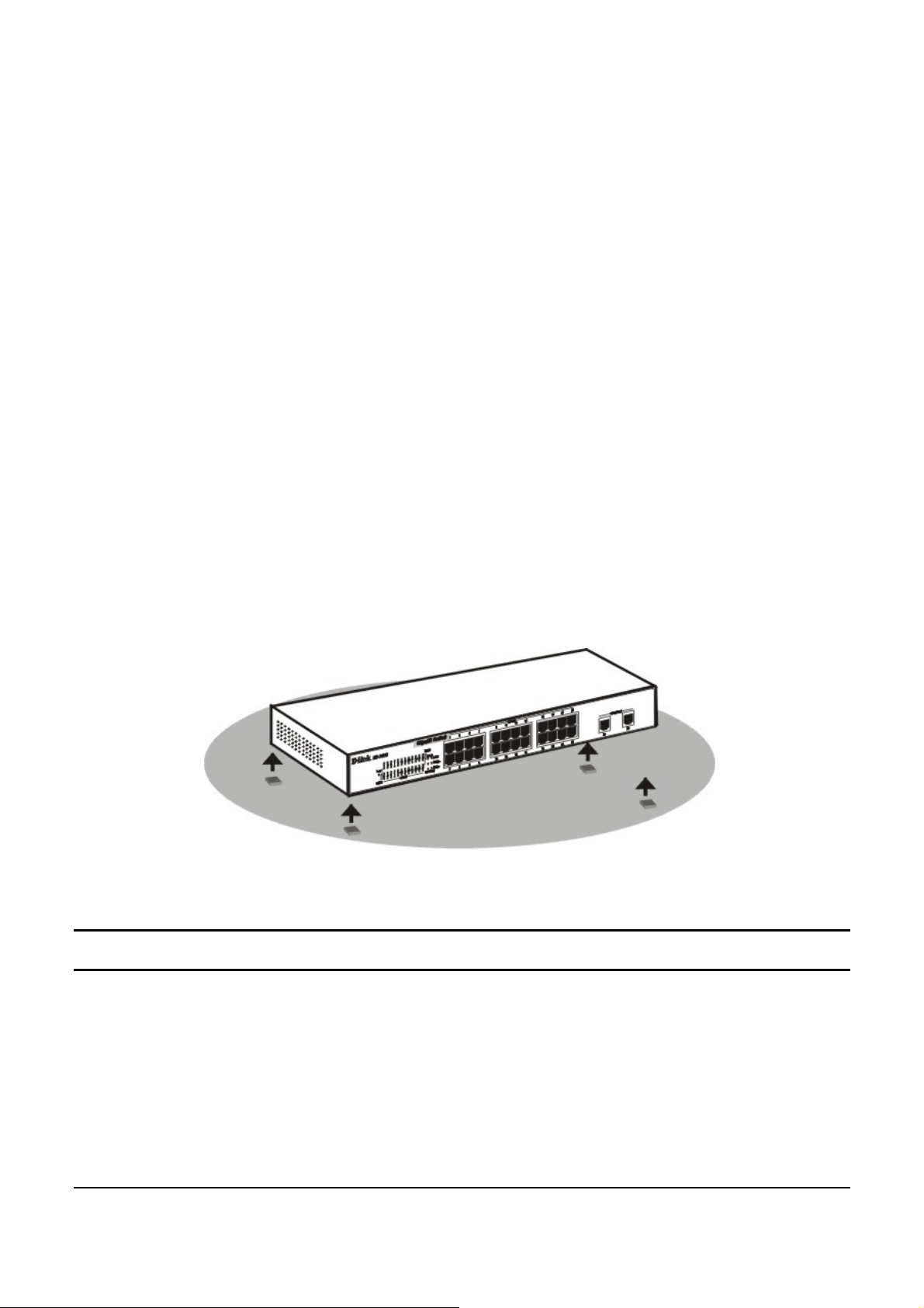
• When installing the Switch on a level surface, attach the
rubber pads (feet) to the bottom. Th e rubber feet cushion the
switch and helps protect the case from scratches.
Figure 1 – Attach the adhe s i ve rubber pads to the bottom
Rack Mounting
The Switch can be mounted in an EIA standard-size, 19-inch rack or
chassis, which can be located in a wiring closet with other equipment.
Attach the mounting brackets to the Switch’s side panels (one on each
side), and secure them with the provided screws.
10
Page 15
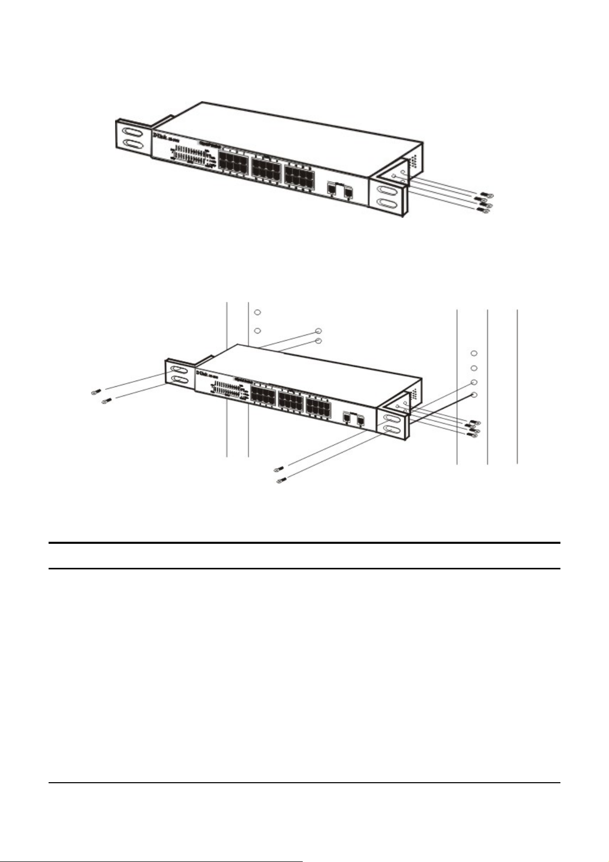
Figure 2 – Attach the mounting brackets to the Switch
Use the screws provided with the equipment rack or chassis to mount
the Switch in the rack.
Figure 3 – Mount the Switch in the rack or chassis
Connecting Network Cable
The Switch supports 1000Mbps Gigabit Ethernet that can operate in
Auto-negotiate mode, and 10Mbps Ethernet or 100Mbps Fast Ethernet
modes that run both in half and full duplex modes, as well as
1000Mbps Gigabit Ethernet that runs in full duplex mode, all while
connected to four-pair Category 5 Cables.
The twenty four RJ-45 ports are all Auto-MDI typ e ports. The Switch
can auto transform to MDI-II or MDI-X type, therefore connections
with standard or crossover RJ45 cables are both supported.
11
Page 16

AC Power
The Switch utilizes an AC power supply of 100-240V AC, 50-60 Hz.
The power switch is located at the rear of the Switch adjacent to the
AC power connector and the system fan. The switch’s power supply
will adjust to the local power source automatically and may be turned
on without having any or all LAN segment cables connected.
12
Page 17
IDENTIFYING EXTERNAL COMPONENTS
This chapter describes the front panel, rear panel, and LED indicators
of the Switch.
Front Panel
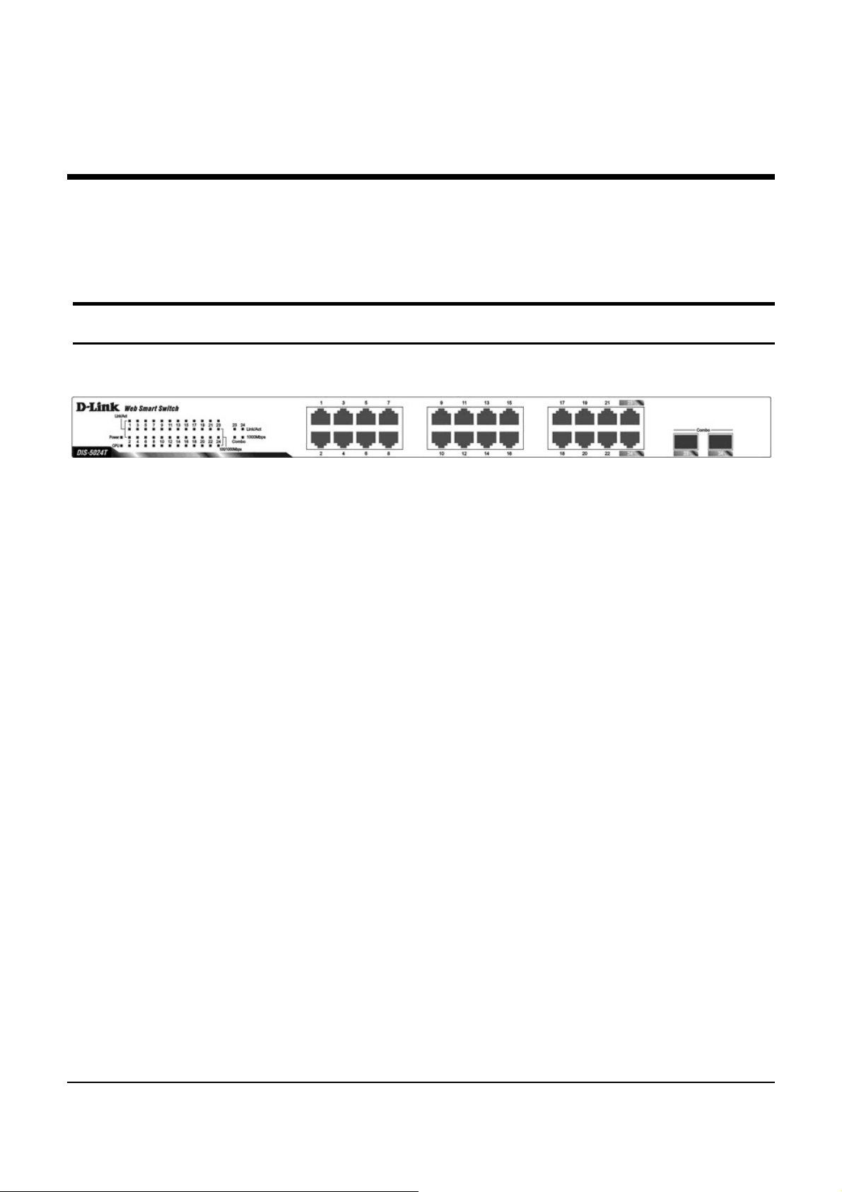
The figure below shows the front panel of the Switch.
Figure 4 – Front panel of the 24-port Web-Smart Switch
LED Indicator:
Comprehensive LED indicators display the status of the switch and
the network (see the Understanding LED Indicators section).
Gigabit Ethernet Ports (Port 1~24):
The Switch includes twenty four Gigabit twisted pair ports, each
supporting auto negotiable 10/100/1000Mbps and auto MDI/MDIX
crossover detection functions. This function provides true “plug and
play” capability. These ports can operate in half-duplex mode for
10/100Mbps and full-duplex mode for 10/100/1000Mbps.
Mini GBIC Ports(Option Port 23~24)
The Switch is equipped with two mini-GBIC ports, supporting an
optional 1000BASE-SX/LX mini-GBIC module.
Note: When a port is set to “Forced Mode”, the Auto MDI/MDIX
will be disabled.
13
Page 18
Rear Panel
●
Reset button
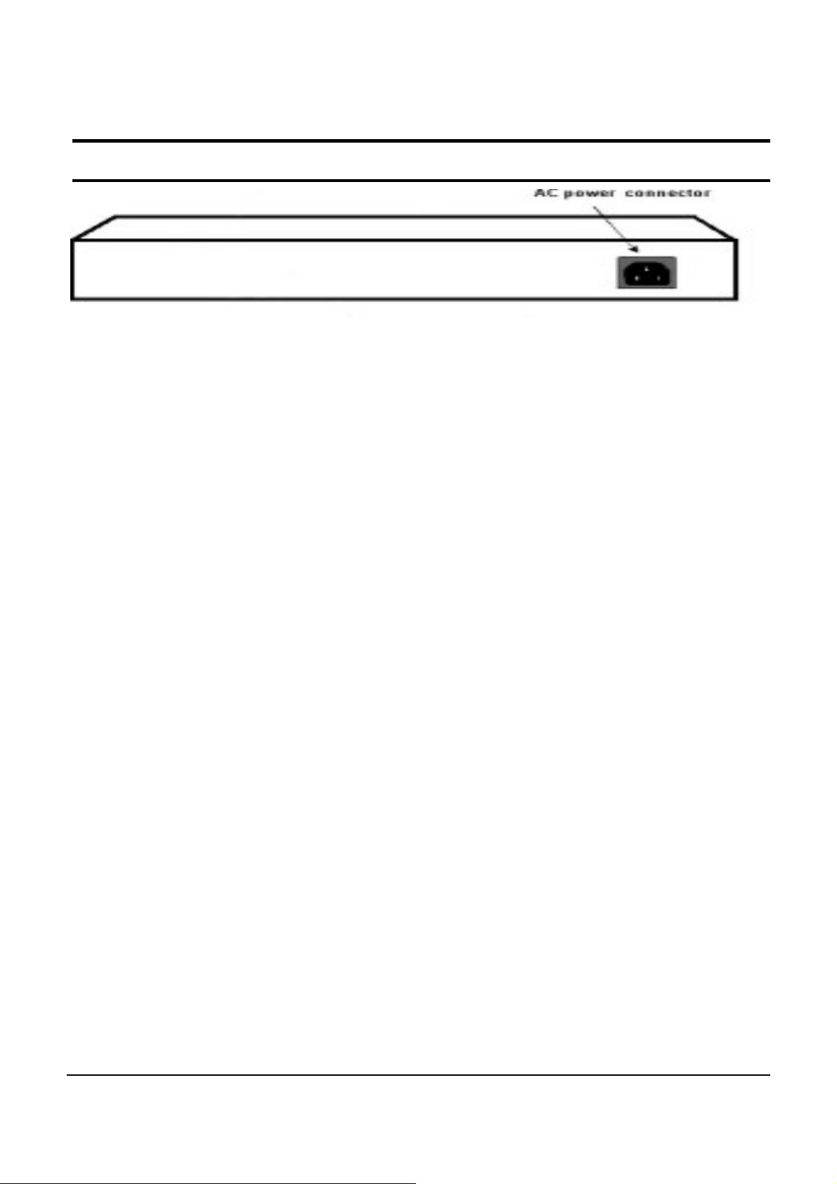
Figure 5 – Rear panel of the Switch
Reset button: The Reset button resets all configuration settings back
to the factory default.
Note: Be sure that to record all custo m settings of the Switch before
pressing the reset button. Resetting the Switch back to factory default
settings will erase all custom configurations.
AC Power Connector: Plug in the female co nnector of the provid ed
power cord into this connector, and the male into a power outlet.
Supported input voltages range from 100-240 V AC, and 50-60Hz.
14
Page 19
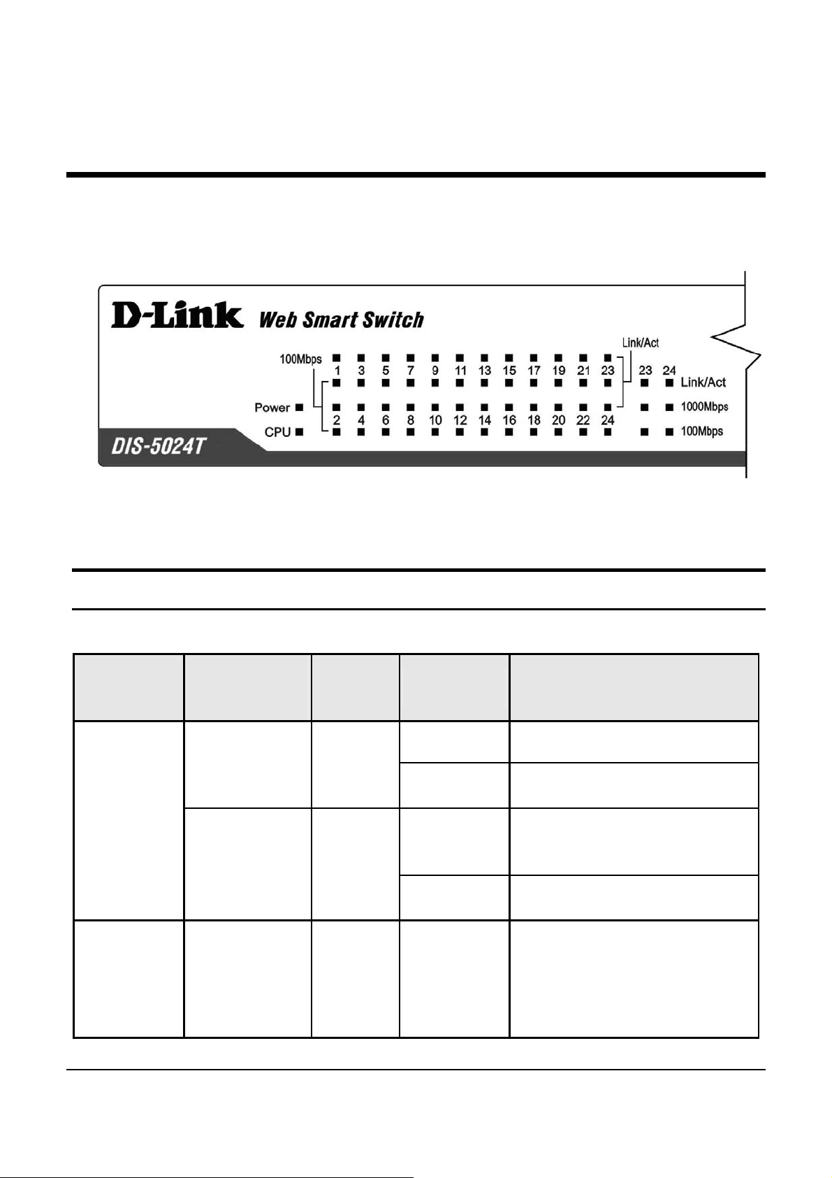
UNDERSTANDING LED INDICATORS
The front panel’s LED Indicators provide instant status feedback,
which help monitoring and troubleshooting LAN issues if needed.
Figure 6 – LED indicators of the Switch
Power and System LEDs
Location
Per Device
LED Per
10/100/
1000 Mbps
LED
Color Status Description
Indicative
Power Green
System Green
Link/Act Green
Solid Light Power is On
Light off Power is Off
When the CPU is working,
Blinking
the System LED will blink
On/Off The CPU is not working
When there is a secure
connection (or link) to an
Solid Light
Ethernet device in any of
Port
the ports
15
Page 20

When there is reception or
Speed
Blinking
Light off No link detected
Green Solid Light
Amber Solid Light
Off Light off
transmission (or Activity)
of data in any port
When there is a secure
connection (or link) to
1000Mbps device in a port
When there is a secure
connection (or link) to
100Mbps device in any of
the ports
Possible link at 10M or no
link
When there is a secure
LED Per
SFP Port
Solid Light
Link/Act Green
Blinking
Light off No link
Green Solid Light
1000Mbps
Off Light off No link
connection (or link) to
Ethernet device in any of
the ports
When there is reception or
transmission (or Activity)
of data occurring in a port
When there is a secure
connection (or link) to a
1000Mbps device in any of
the ports
16
Page 21

CONFIGURATION
Through a web browser, the features and functions of the DIS-5024T
Switch can be config ured for optimum use .
Supported web browsers
The embedded Web-based Utility currently supports the following
web browsers:
• Microsoft Internet Explorer ver. 6.0, 5.5
• Mozilla ver. 1.7.12, 1.6
• Firefox ver. 1.5, 1.0.7
• Netscape ver. 8.0.4, 7. 2
• Opera ver. 8.5, 7.6
• Safari ver. 2.0.2
Installing the SmartConsole Utility
The following instructions provide guidance to install the
SmartConsole Utility.
1. Insert the Utility CD in the CD-Rom Drive.
2. From the Start menu on the Windows desktop, choose Run.
3. In the Run dialog box, type D:\SmartConsole Utility\setup.exe
(D:\ depends where your CD-Rom drive is located) and click OK.
4. Follow the on-screen instructions to install the utility program.
5. Upon completion, go to Program Files -> SmartConsole Utility
and execute the SmartConsole Utility.
17
Page 22
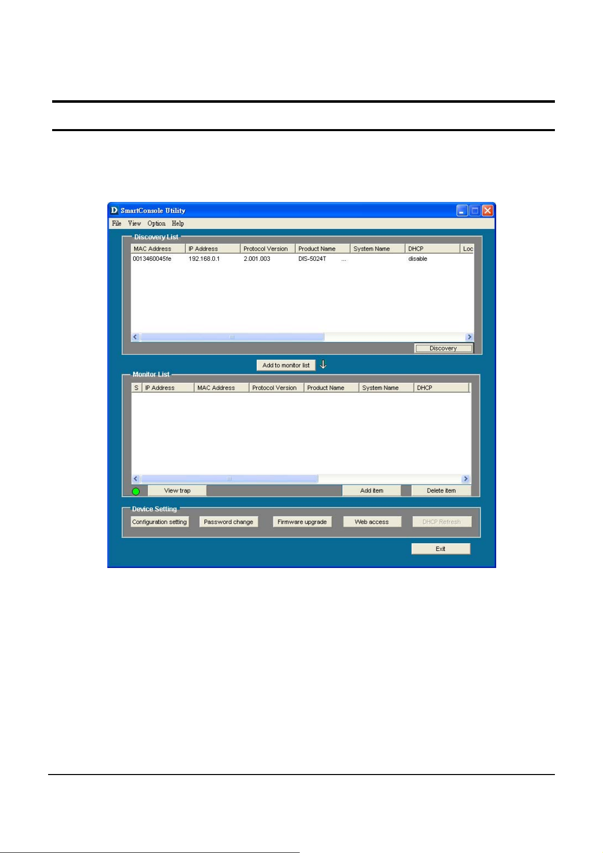
SmartConsole Utility Features
The SmartConsole Utility is divided into four parts, a Menu Toolbar
of functions at the top, Discovery List, Monitor List, and Device
Setting.
Figure 7 – SmartConsole Utility
18
Page 23

Menu Toolbar
The Menu Toolbar in the SmartConsole Utility has four main tabs,
File, View, Option, and Help.
File
includes: Monitor save, Monitor save as, Monitor load and Exit.
• Monitor Save: To record the setting of the Monitor List as
default for the next time the SmartConso le Utility is used.
• Monitor Save As: To record the setting of the Monitor List
in an appointed filename and f ile path.
• Monitor Load: To manually load a Monitor List setting file.
• Exit: To exit the SmartConsole Utility.
View
setting list operations.
Option
includes: View log and Clear Log functions, wh ich provide trap
• View Log: To show the event of the SmartConsole Utility
and the device.
• Clear Log: To clear all log entries.
includes: Refresh Time and Group Timer functions.
• Refresh time refreshes the monitoring time of the device.
Choices include 15 secs, 30 secs, 1 min, 2 min and 5 min for
selecting the mon itor ing time intervals.
19
Page 24
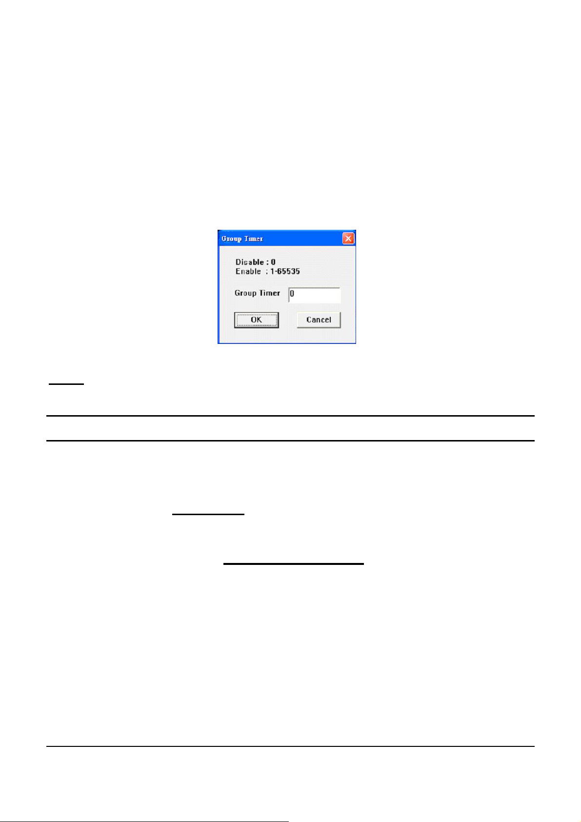
• Group Timer establishes the intervals (in seconds) that the
Web-Smart Switch will be discovered in the SmartConsole
Utility Discovery List.
NOTE: If the Group Timer is set to 0, IGMP snooping must be
disabled or else the Web-Smart Switch will not be discovered.
Help
the software version.
Discovery List
This is the list where all Web-Smart devices on the network are
discovered.
By pressing the Discovery
listed in the discovery list.
Double click or press the Add to monitor list
from the Discovery List to the Monitor List.
Definitions of the Discovery List feat ures:
MAC Address: Shows the device MAC Address.
includes: information About the SmartConsole Utility, such as
button, all the Web-Smart devices are
button to select a device
IP Address: Shows the current IP addresses of devices.
Protocol version: Shows the version of the Utility protocol.
Product Name: Shows the device product name.
20
Page 25

System Name: Shows the appointed device system name.
DHCP: uses a client/server model to obtain lease of an IP address
from a DHCP server as part of the network boot process.
Location: Shows where the appointed device location.
Trap IP: Shows the IP where the Trap information will be sent.
Subnet Mask: Shows the Subnet Mask set of the device.
Gateway: Shows the Gateway set of the device.
Monitor List
All Web-Smart devices in the Monitor List can be monitored, with
Trap information available to be received for monitoring status
information of the device.
Definitions of the Monitor List functions and terms:
S: Shows the system symbol of the Web-Smart device,
the device system is inactive.
IP Address: Shows the current IP address of the device.
MAC Address: Shows the device MAC Address.
Protocol version: Shows the version of the Utility protocol.
Product Name: Shows the device product name.
System Name: Shows the appointed device system name.
DHCP: uses a client/server model to obtain lease of an IP address
from a DHCP server as part of the network boot process.
Location: Shows where the device is located.
Trap IP: Shows the IP where the Trap to be sent.
Subnet Mask: Shows the Subnet Mask set of the device.
represents
Gateway: Shows the Gateway set of the device.
21
Page 26
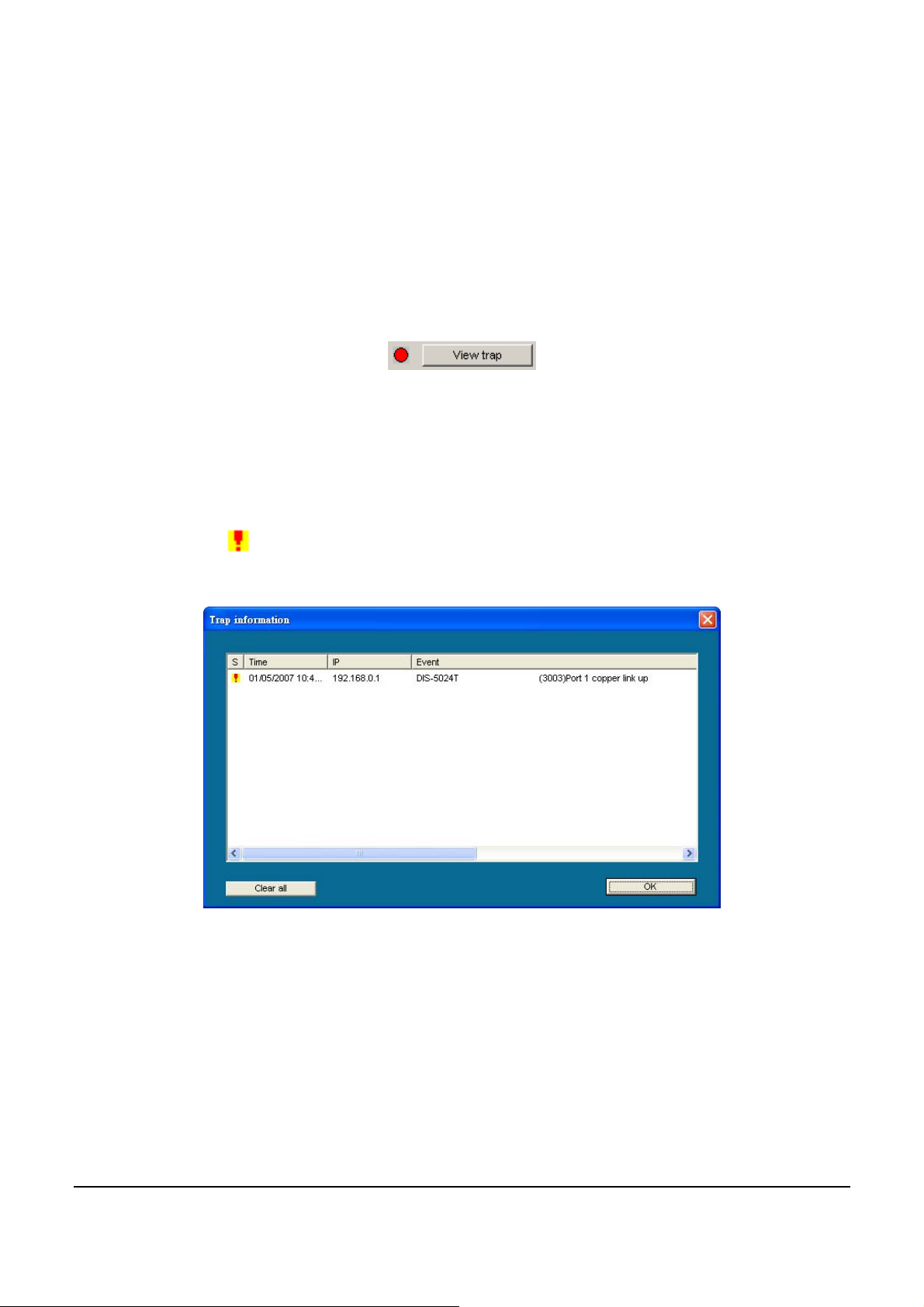
View Trap: The Trap function works to receive the events configured
in the Web-Smart Switch from the Monitor List.
There is a light indicator fo llowing the “View Trap” button. When the
light indicates in green, no new traps are available. When red, a new
trap indicates a new trap is available. (Figure 8)
Figure 8 – View t r ap
When the “View Trap” button is clicked, a Trap Information window
will pop up, showing the trap information, such as Symbol, Time,
Device IP and the Event occurred. (Figure 9)
The symbol “
” represents a new trap signal, and will disappear after
the event record is reviewed (clicked).
Figure 9 – Trap information
Note: To receive Trap information, the switch must be configured
with Trap IP and Trap Events, available from th e Tr ap Settin g menu.
Add Item: Adds a device to the Monitor List manually, by entering
the IP Address of the device to monitor.
Delete Item: Deletes the device from the Monitor List.
22
Page 27
Device Setting
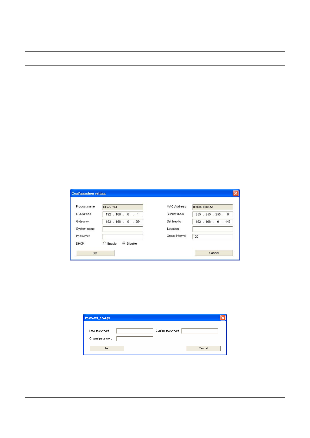
Function buttons of the Device Setting section provide several options.
Configuration Setting: In the Configuration Setting, the following
settings are available: Product Name, MAC Address, IP Address,
Subnet Mask, Gateway, Set Trap to (Trapping IP Address), System
name, Location, Password and DHCP ON/OFF (OFF is default).
After selecting the device from the Discovery List or Monitor List and
pressing Configuration Setting, modify the information necessary and
press “Set”.
Figure 10 – Configuration Setting
Password Change: To change the password, fill in the new and
original password, and press “Set”.
Figure 11 – Password Change
23
Page 28
This space has been intentionally reserved for notes:
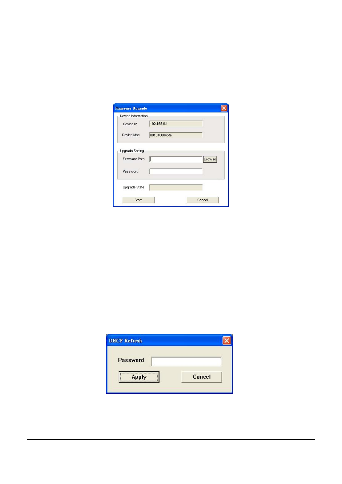
Firmware Upgrade: When the device firmware is be upgraded, enter
the Firmware path and password (if necessary) to update.
Figure 12 – Firmware Upgrade
Web Access: Double click the device in the Monitor List or select a
device in the Monitor List and press the “Web Access” button to open
the Web-based Utility. To see the list of web browsers the Web-based
Utility supports, see Supported web browsers on page 20.
DHCP Refresh: select a device in the Monitor List and press the
“DHCP Refresh”, and enter the password (if applicable) to trigger
the Web-Smart Switch to request an IP address from a DHCP Server.
Figure 13 – DHCP Refresh
24
Page 29

Web-based Utility
The DIS-5024T Web-Smar t Switch has a web browser GUI in terface
for configuring the Switch through a web browser. To see the list of
web browsers the Web-based Utility supports, see Supported web
browsers on page 20. A network administrator can manage, control
and monitor the Switch from a PC on the local LAN. This section
describes how to operate the functions found in the Web-based Utility.
Login
Before beginning to configure the Web-Smart Switch through a web
browser over an Ethernet connection, the PC used to manage the
Switch must reside on th e same the IP network . By defau lt, th e Switch
automatically obtains an IP address from a DHCP Server. The admin
configuring the Switch must check the LAN’s DHCP Server to
identify the IP Address assigned to the Switch. The default IP address
is 192.168.0.1 if the Switch cannot successfully obtain an IP address
from a DHCP Server. If the DHCP assigned IP address of the WebSmart Switch is 192.168.0.1, then the managing PC should use
192.168.0.x (where x is a numb er b etw een 2 and 25 4) as its I P addr ess,
with a subnet mask also being the same (255.255.255.0 if not assigned
by a DHCP Server). To begin, open a supported web browser and
enter the IP address of the Switch (ex http://192.168.0.1).
Figure 14 – Logging into the Switch’s (DHCP assigned) IP address
Alternatively, through the SmartConsole Utility, when the Switch is
discovered, select the device shown in the Monitor List of the
SmartConsole Utility to open the device in a web browser.
25
Page 30
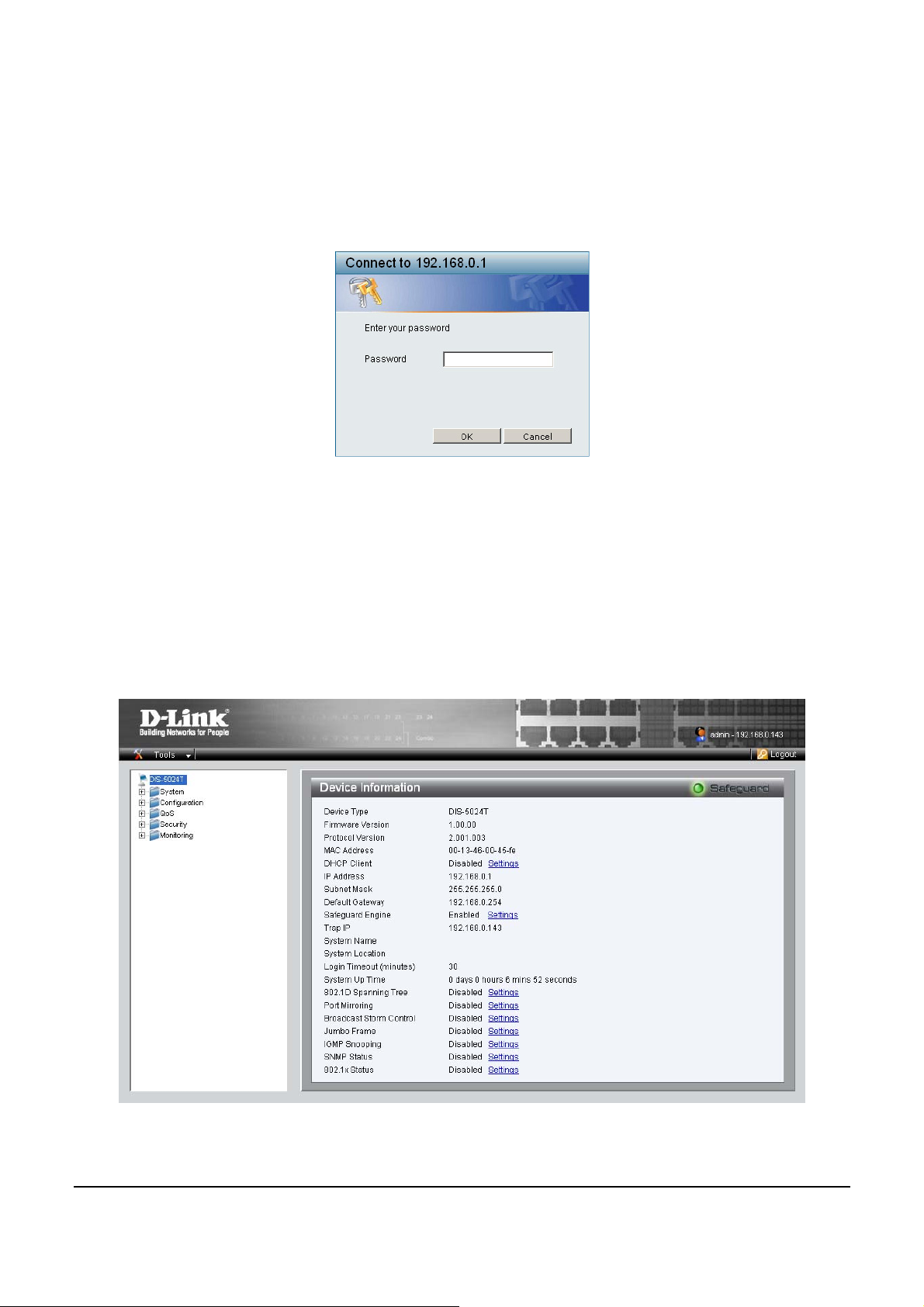
When the following dialog appears, (the actual IP address will
correspond with the IP address of the Switch), enter the default
password "admin" and press OK to enter the main Web-based Utility.
Figure 15 – Log in screen
After entering the password, the main page of the Web-based Utility
displays the status of the Switch. In the top right corner the user name
(default ‘admin’) is displayed with the IP address of the Switch.
Below this is a Logout option for use when the session is complete.
Figure 16 – Device Status
26
Page 31
Tool Menu
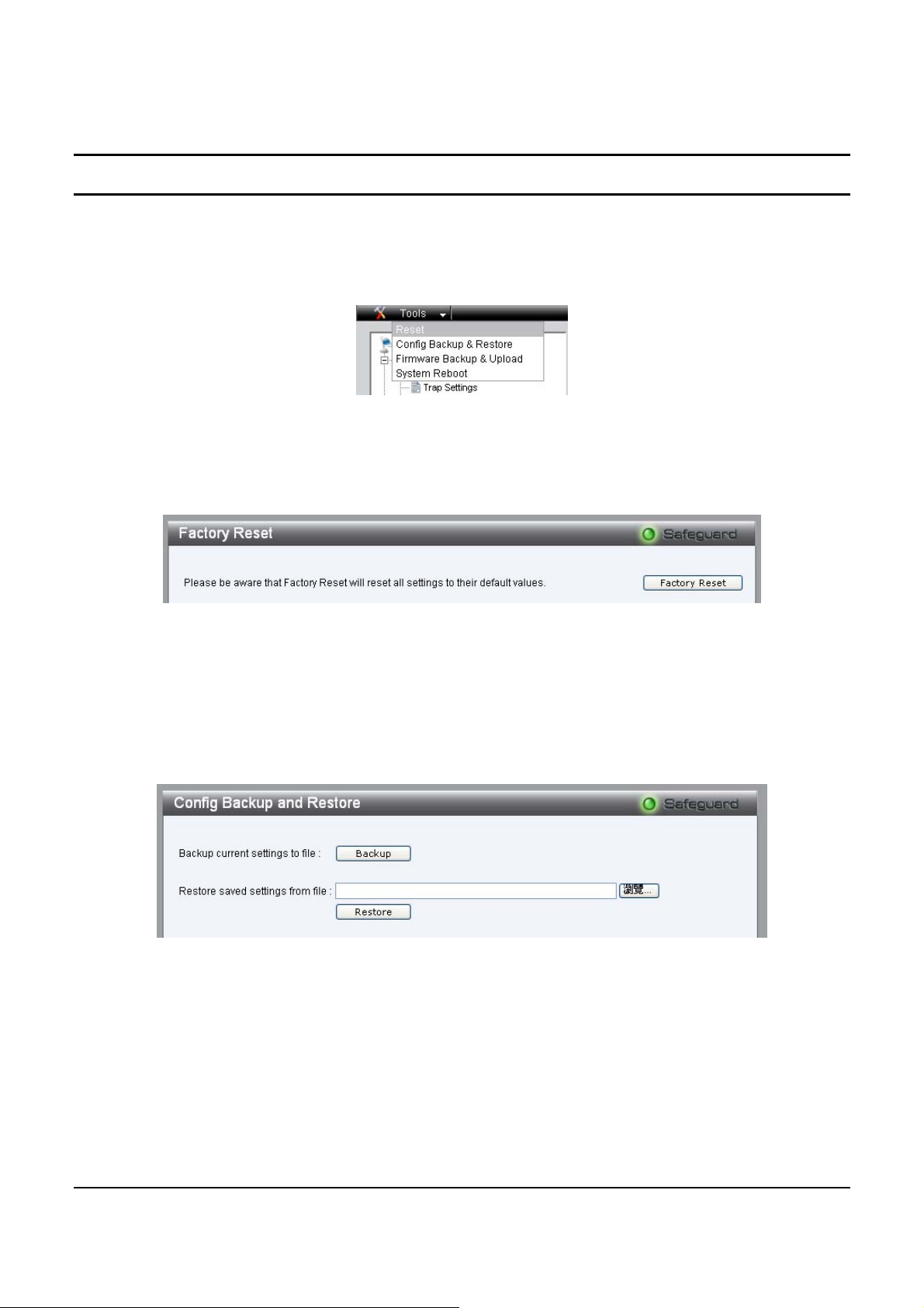
The Tool Menu offers global function controls such as Reset,
Configuring Backup and Restoration, Firmware Backup and Upload,
and System Reboot.
Figure 17 – Tool Menu
Reset: Provides a safe reset option for the Switch.
Figure 18 – Tool Menu > Reset
Configure Backup and Restore: Allows the current configuration
settings to be saved to a file (not including the password), and if
necessary, to be restored from a backup.
Figure 19 – Tool Menu > Configure Backup and Restore
Firmware Backup and Upload: Allows for the firmware to be saved,
or for an existing firmware file to be uploaded to the Switch.
27
Page 32
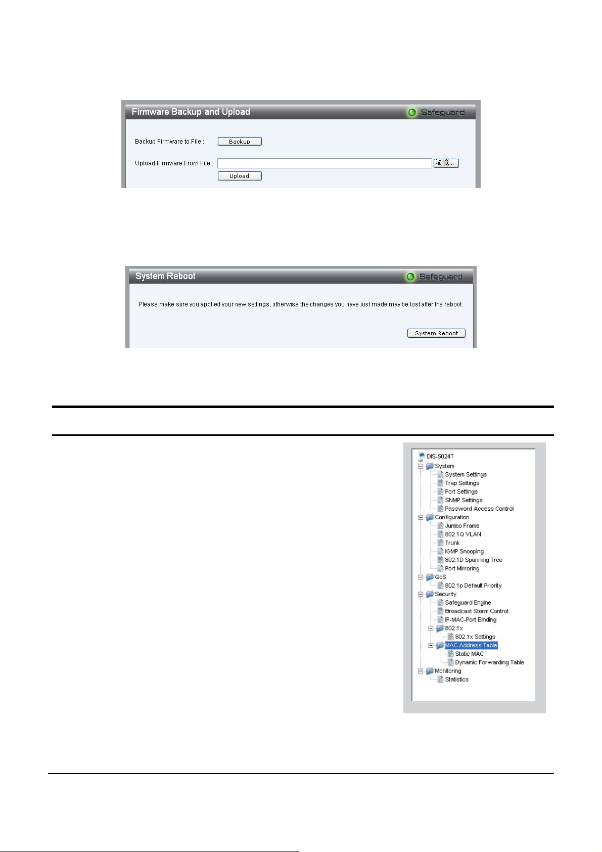
Figure 20 – Tool Menu > Firmware Backup and Upload
System Reboot: Provides a safe way to reboot the system.
Figure 21 – Tool Menu > System Reboot
Setup Menu
When the Web-based Utility appears, a Setup
Menu on the left side of the screen provides an
organization of links to pages for specific
feature and function configurations and
properties. The following sections describe in
more detail each of the featu res and functions.
Figure 22 – Setup Menu
28
Page 33
System > System Setting
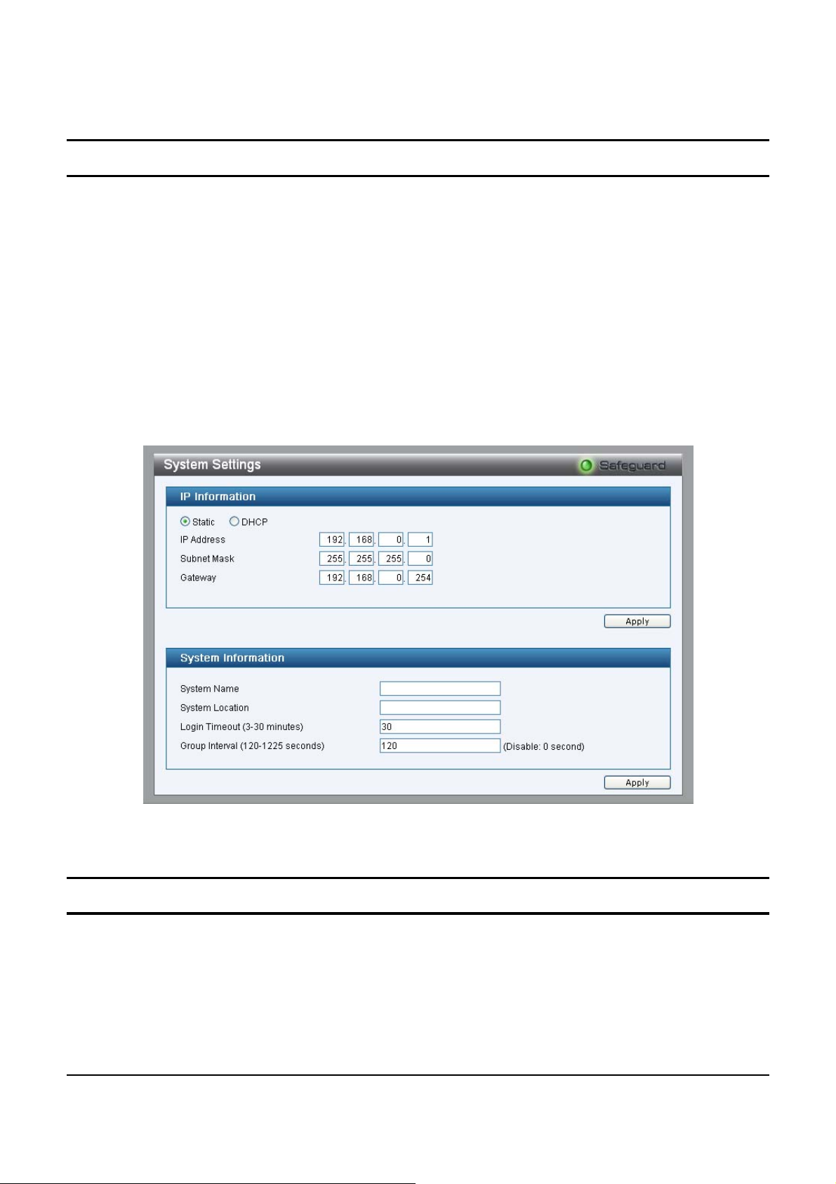
The System Setting includes IP Information and System information.
By default DHCP is disabled. If DHCP is disabled, the IP Address,
Subnet Mask and Gateway can be manually conf igured. By entering
a System Name and System Lo cation, the device can more easily be
recognized through the Sma rtConsole Utility and in other Web-Sma rt
devices on the LAN. The Login Timeout controls the idle time-out
for security purposes, when there is no action in the Web-based Utility.
When the Login Timeout expires, the Web-based Utility requires a relogin before using the Uti lity again.
Figure 23 – Syst e m > System Setting
System > Trap Setting
A Trap Setting allows the Web-Smart Switch to monitor Trap
information through the Web-based Utility of an IP address on the
LAN. By default, Trap Setting is Disabled. When the Trap Setting is
29
Page 34
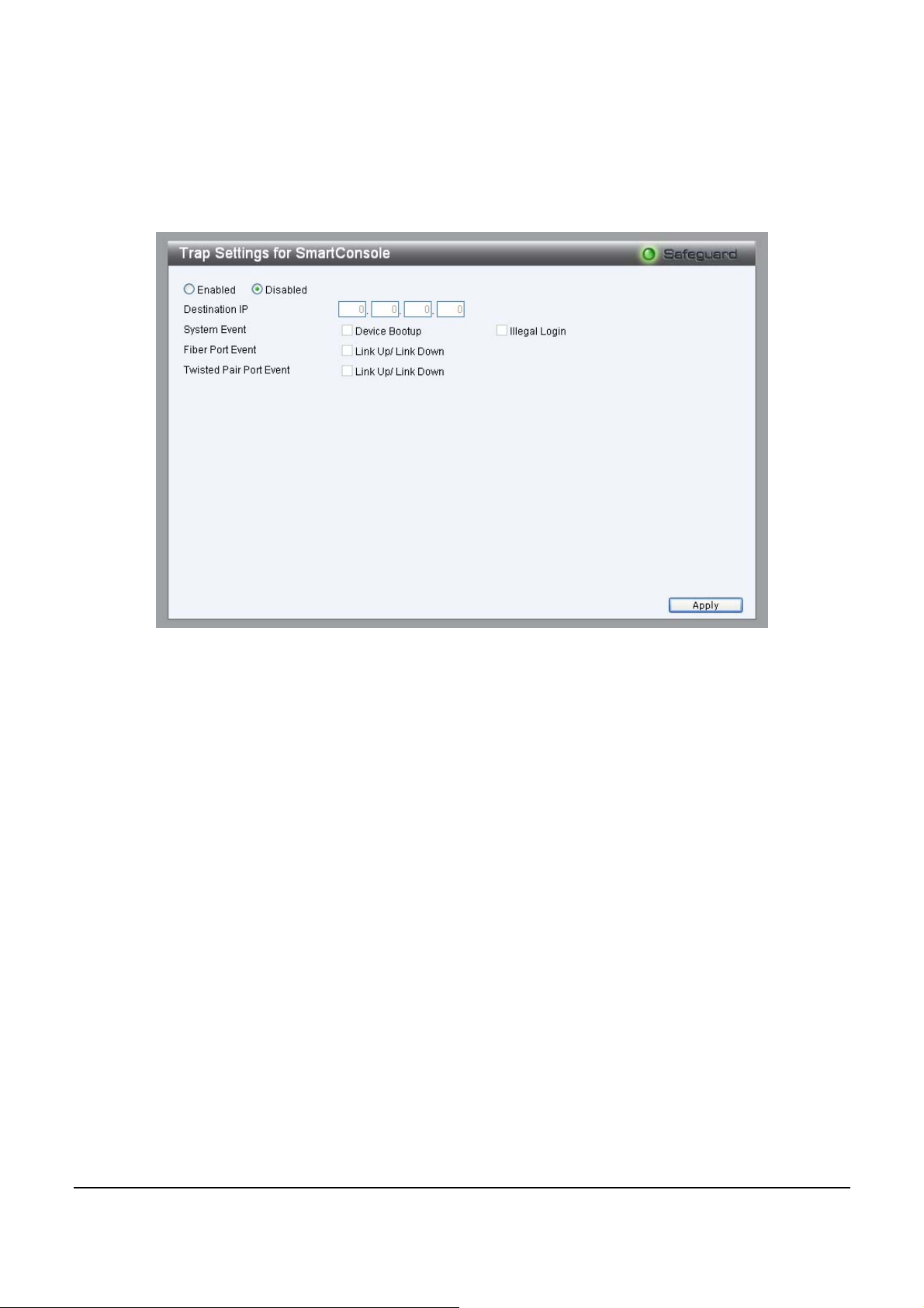
Enabled, enter the Destination IP address of the managing PC that
will receive trap information.
Figure 24 – System > Trap Setting
System Event: Monitors the system’s trapping information.
Device Bootup: Traps system boot-up inform ation.
Illegal Login: Traps events of incorrect password logins,
recording the IP of the originating PC.
Fiber Port Events: Monitors the fiber port status.
Link Up/Link Down: Traps fiber connection information.
Twisted pair Port Eve nts: Monitors the copper cable port status.
Link Up/Link Down: Traps copper connection info rm ation.
30
Page 35
System > Port Setting
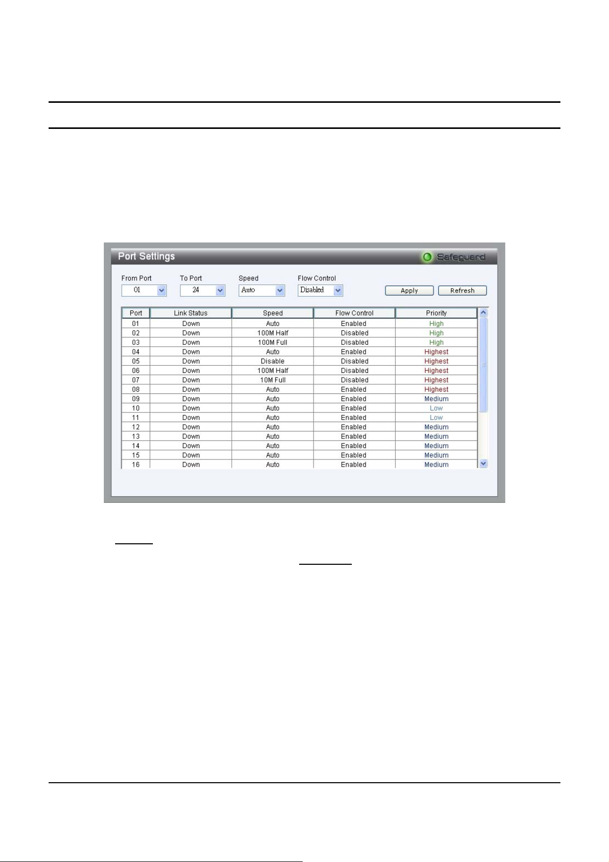
In the Port Setting page, the status of all ports can be monitored and
adjusted for optimum configuration. By selecting a range of ports
(From Port and To Port), the Speed and Flow Control can be set for
all such ports, by clicking Apply. To refresh the information table to
view the latest Link Status and Priority, press the Refresh button.
Figure 25 – System > Port Setting
Speed: Fiber connections can operate in Forced Mode settings
(1000M Full), Auto, or Disable. Copper
connections can operate in
Forced Mode settings (100M Full, 100M Half, 10M Full, 10M Half),
Auto, or Disable. The default setting for all ports is Auto.
NOTE: Be sure to adjust port speed settings appropriately after
changing connected cable media types .
Flow Control: This setting determines if the Switch handles flow
control. Set to Enable to avoid data transfer overflows. Default setting
for all ports is Disable.
31
Page 36
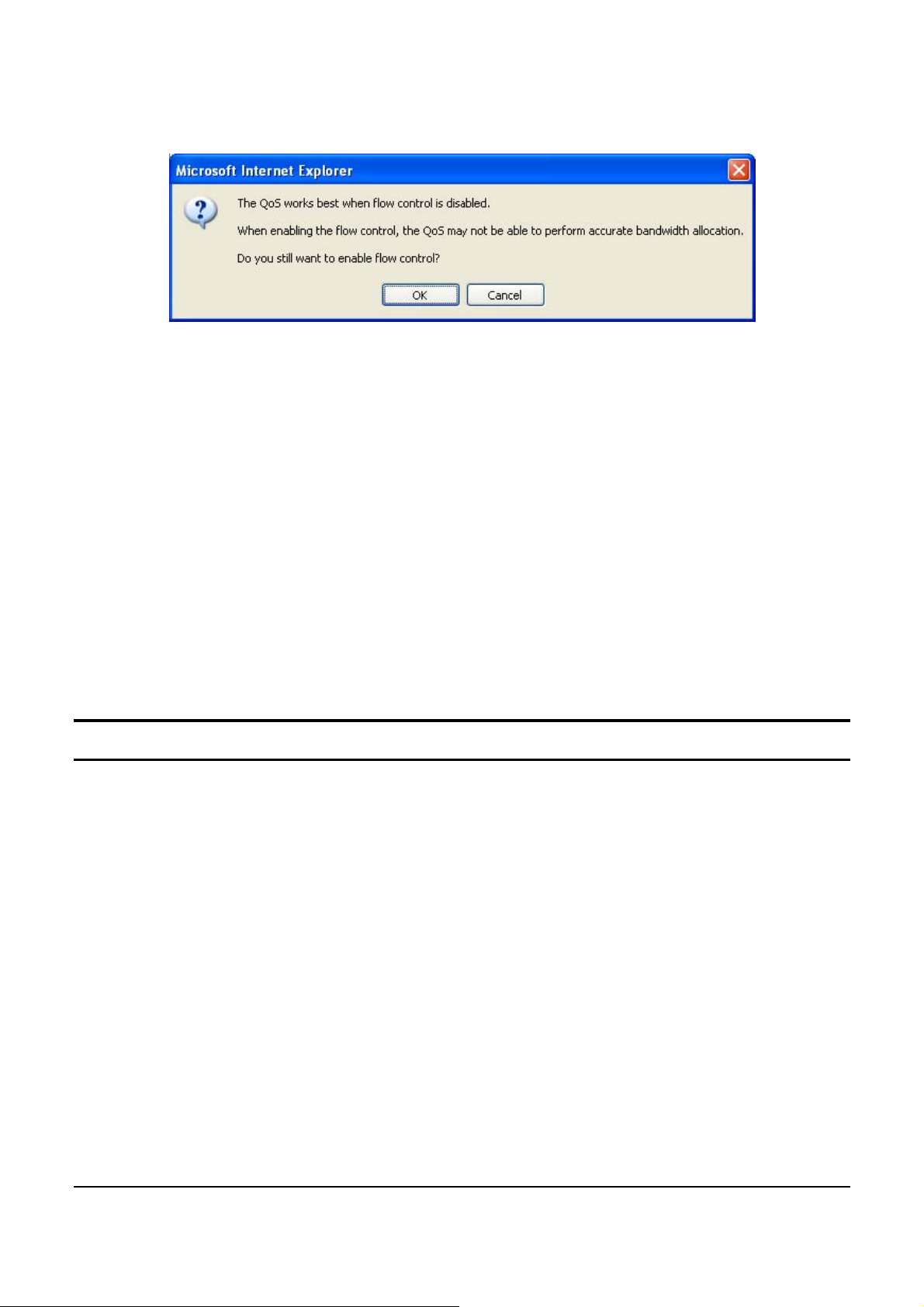
NOTE: When user enable flow control at the first time, the
message will pop up.
Link Status: Reporting Down indicates the port is disconnected.
Priority: Displays each port’s 802 .1P QoS priority level for received
data packet handling. Default setting for all ports is Middle.
NOTE: The priority of Gigabit Fiber ports are by default higher
than Copper ports.
System > SNMP Setting
Simple Network Management Protocol (SNMP) is an OSI Layer 7
(Application Layer) designed specifically for managing and
monitoring network devices. SNMP enables network management
stations to read and modify the settings of gateways, routers, switches,
and other network devices. Use SNMP to configure system features
for proper operation, monitor performance and detect potential
problems in the Switch or LAN.
Managed devices that support SNMP include software (referred to as
an agent), which runs locally on the device. A defined set of variables
(managed objects) is maintained by the SNMP agent and used to
manage the device. These objects are defined in a Management
Information Base (MIB), which provides a standard presentation of
32
Page 37
the information controlled by the on-board SNMP agent. SNMP
defines both the format of the MIB specifications and the protocol
used to access this information over the network.
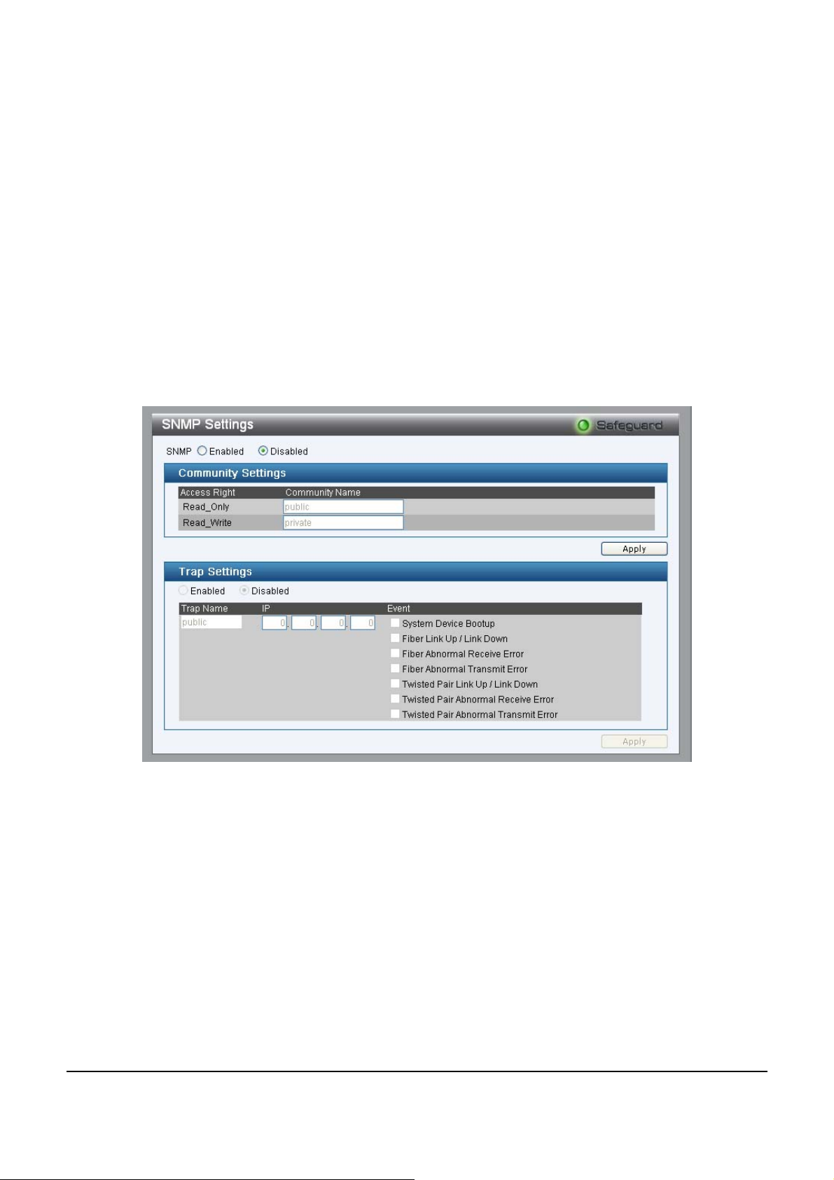
Community Setting: In support of SNMP version 1, the Web-Smart
Switch accomplishes user authentication by using Community
Settings that function as passwords. The remote user SNMP
application and the Switch SNMP must use the same community
string. SNMP packets from a station that are not authenticated are
ignored (dropped).
Figure 26 – System > SNMP Setting
Enabled / Disabled: Default setting is Disabled. Click Enable, then
Apply, to set Community Settings.
The default community strings for the Switch used for SNMP v.1
management access are:
Public: The community with read-only privilege allows
authorized management stations to retrieve MIB objects.
33
Page 38

Private: The community with read/write privilege allows
authorized management stations to retrieve and modify MIB
objects.
Trap Setting: Traps are messages that alert network personnel of
events that occur on the Switch. Such events can be as serious as a
reboot (someone acciden tally turned the Switch OFF), or less serious
events such as a port status change. The Switch can generate traps and
send them to the trap recipient (i.e. network administrator).
Setting up a Trap: Select Enable, enter a Trap Name (i.e. Trap Name
must be selected from a Community Name), add the IP of the device
to be monitored, and choose the event(s) to trap. The available trap
Events to choose from include: Syst em Device Bootup, Fiber Link Up
/ Link Down, Fiber Abnormal Receive Error, Fiber Abnormal
Transmit Error, Twisted Pair Link Up / Link Down, Twisted Pair
Abnormal Receive Error, Twisted Pair Abnormal Transmit Error.
34
Page 39
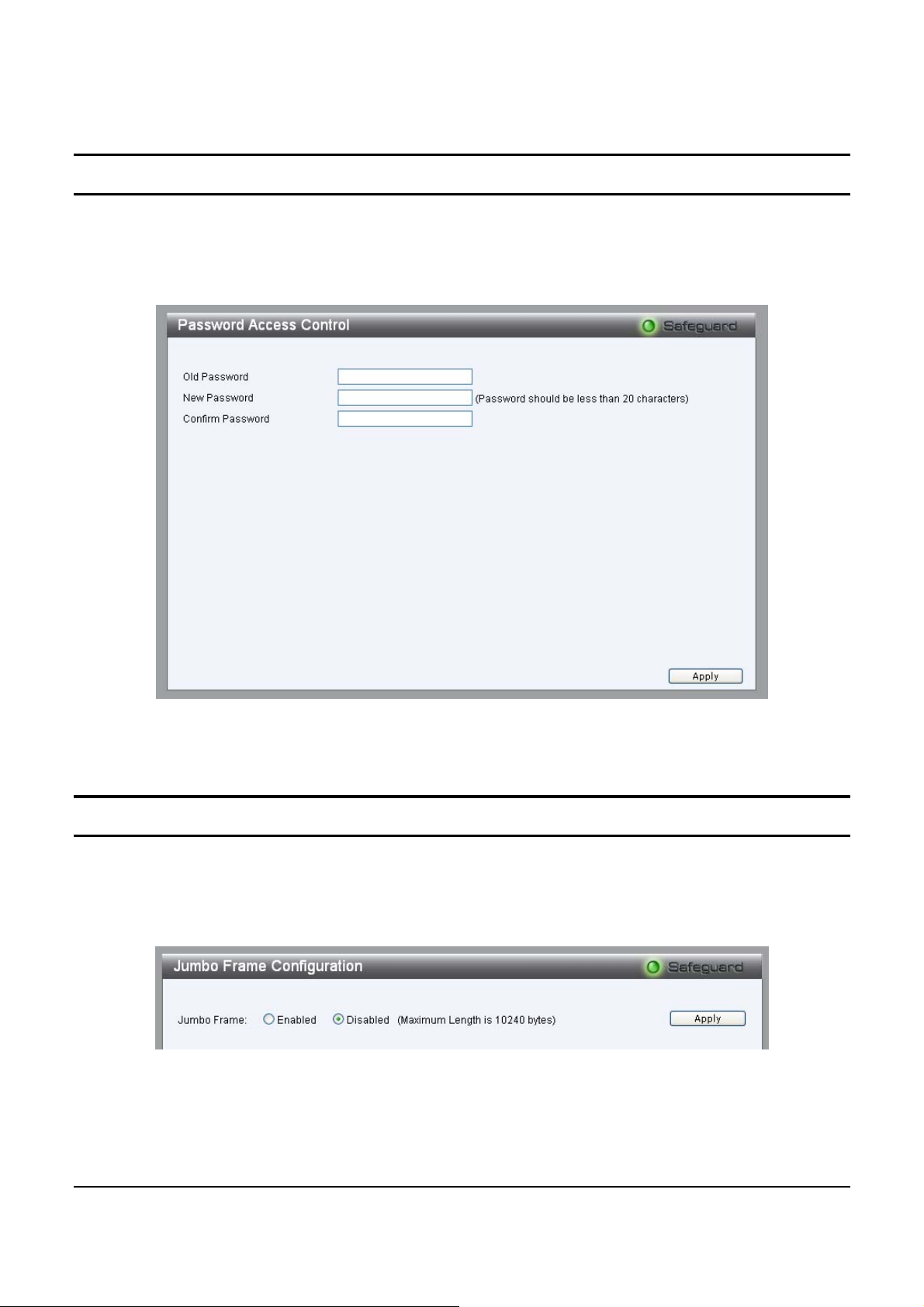
System > Password Access Control
Setting a password is a critical tool for managers to secure the WebSmart Switch. After entering the old password and the new password
two times, press Apply for changes to take effect.
Figure 27 – System > Password Access Control
Configuration > Jumbo Frame
By default, the Jumbo Frame func tion is set to D isabled . Enabling this
function will allow the Switch to receive packets sizes of up to 10,240
bytes.
Figure 28 – Configuration > Jumbo Frame
35
Page 40
Configuration > 802.1Q VLAN
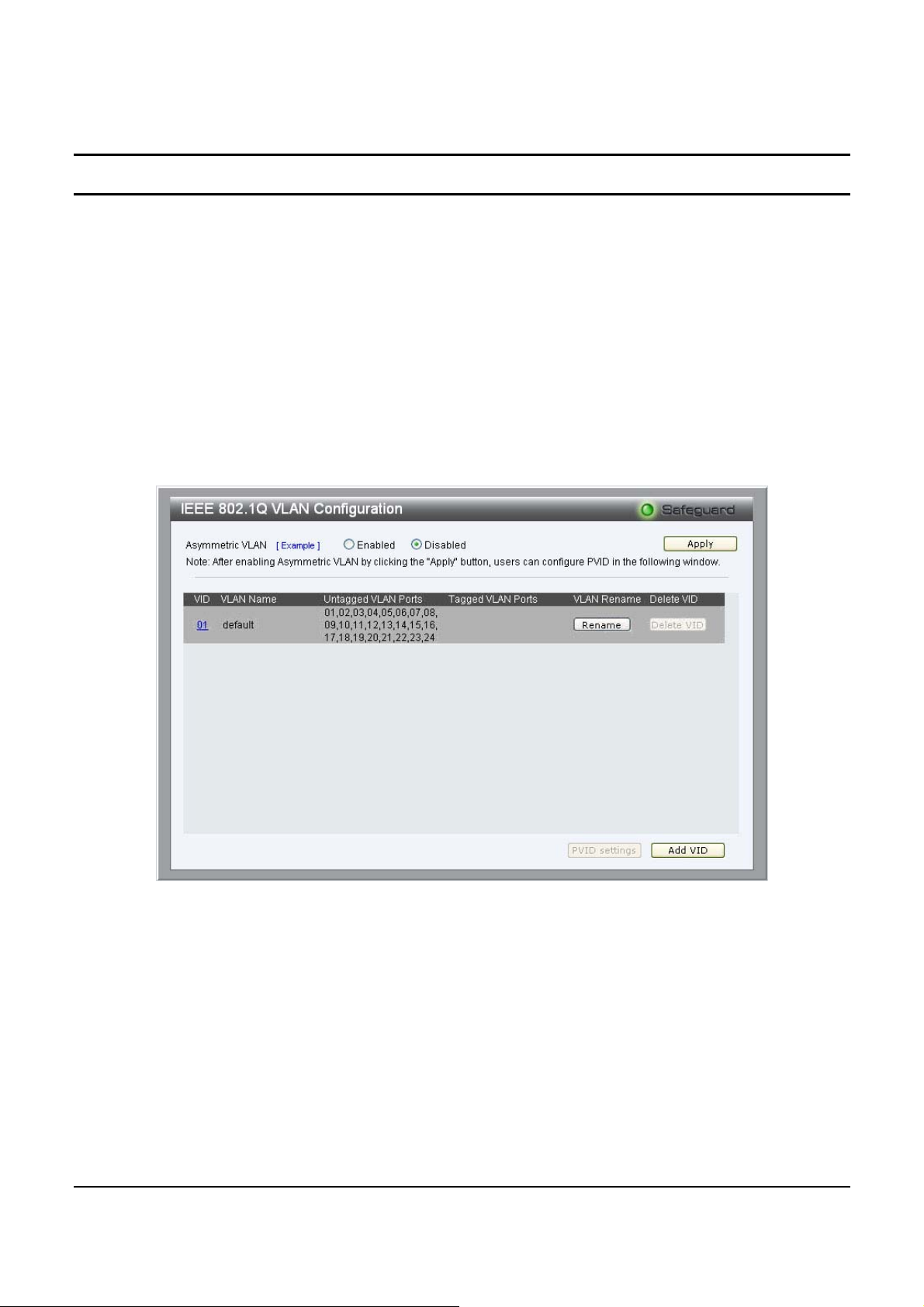
The IEEE 802.1Q VLAN Configuration page provides powerful VID
management functions. By default, VID is 01, is named “default”, and
includes all 24 po rts as “Untagge d” (see Figure 29).
Rename: Press to rename the VLAN group.
Delete VID: Press to delete the VLAN group.
Add New VID: Press to create a new VID group, assigning ports
from 01 to 24 as Untag, Tag, or Not Member. A port can be
“Untagged” i n onl y one VID. To save the VID gr ou p, pre s s Apply.
Figure 29 – Configuration > 802.1Q VLAN > Default Setting
36
Page 41
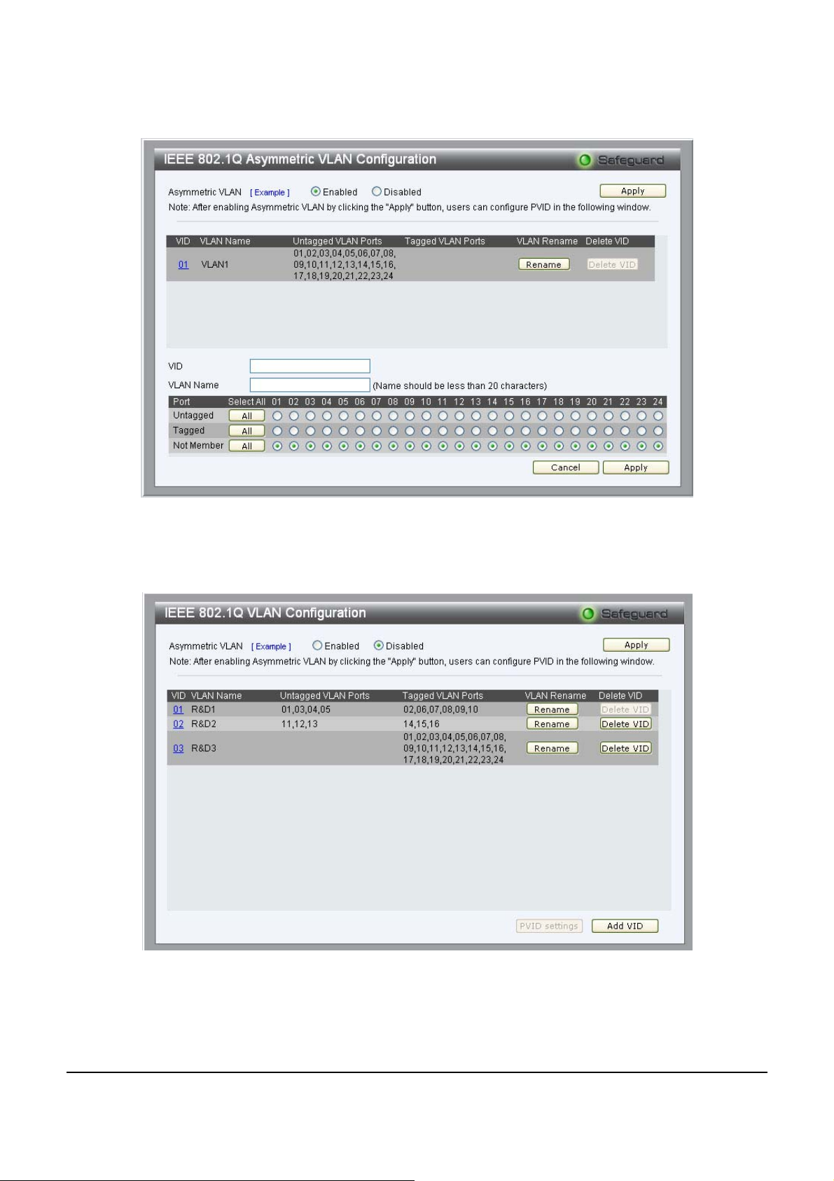
Figure 30 – Configuration > 802.1Q VLAN > Add VID
Figure 31 – Configuration > 802.1Q VLAN > Example VIDs
37
Page 42
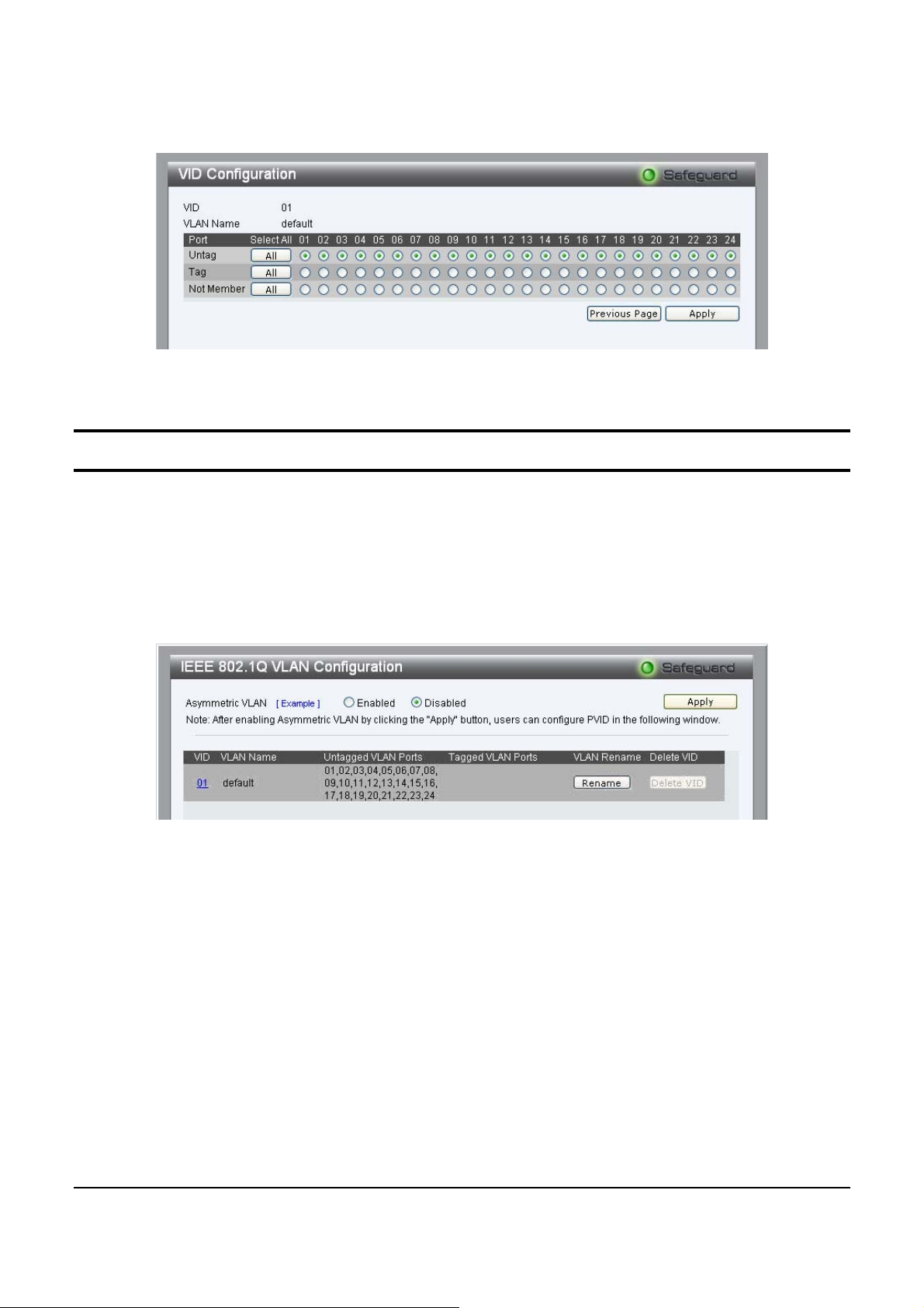
Figure 32 – Configuration > 802.1Q VLAN > VID Assignments
Configuration > Asymmetric VLAN
This function located in the 802.1Q Configuration page, it allows
devices in different VLANs to communicate with the servers,
firewalls or other shared resource in the shared VLAN. This
configuration is accomplished through the use of three steps: enabling
Asymmetric VLAN, VLAN creation, and PVID setting.
Figure 333 – Confi gur ation > 802.1Q VLAN > Configure Asymmetric VLAN
38
Page 43
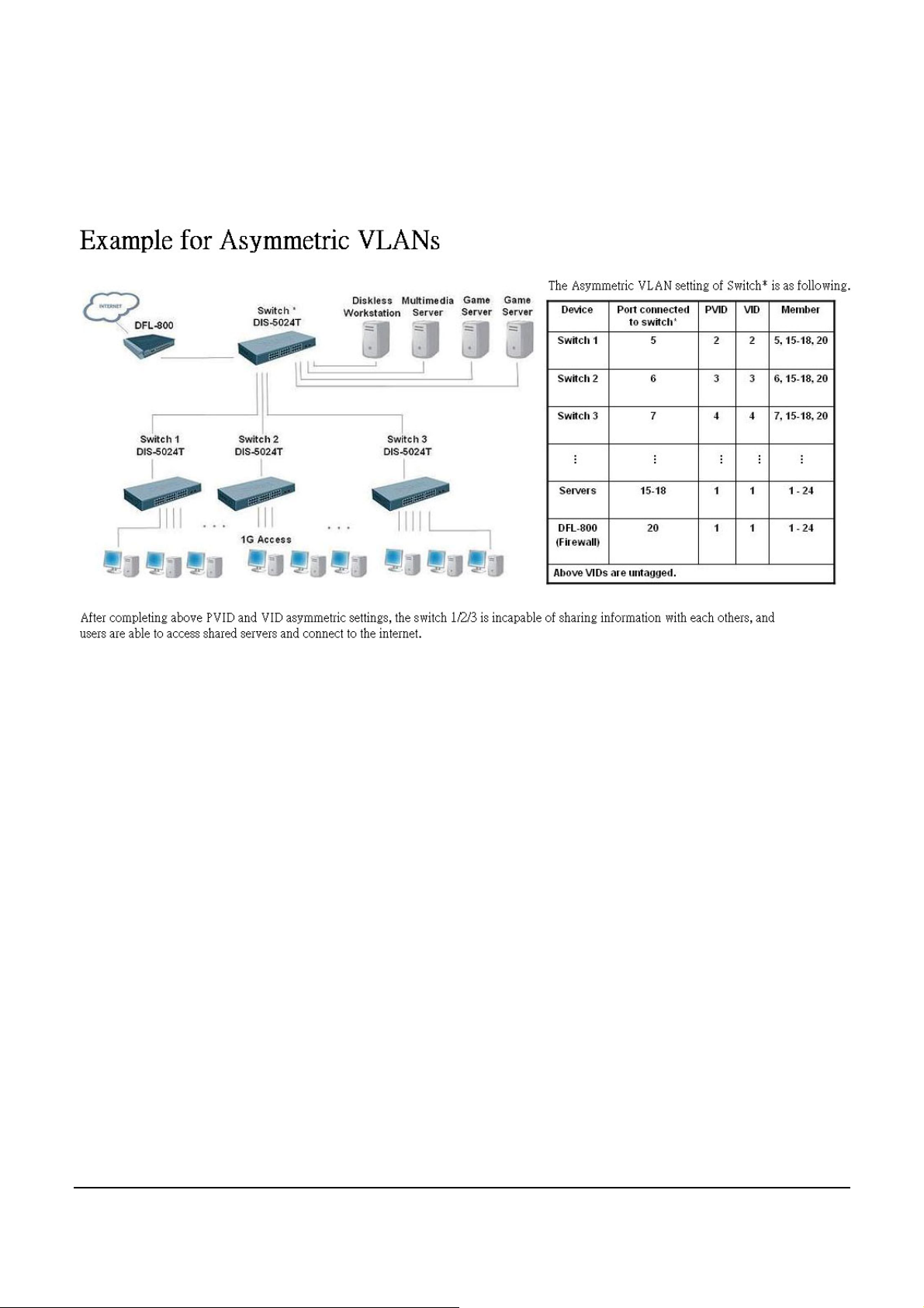
Click “Example” to open the page and follow the instructions below
to configure Asymmetric VLAN
Figure 344 – Configuration > 802.1Q VLAN > Example of Asymmetric VLAN
1. Enable Asymmetric VLAN and click “Apply” button. The
overlapping VLAN cannot be configured unless this function is
enabled.
2. Configure the VLAN settings. The example above uses ports 15-18
and 20 to hold the servers and firewall to be shared on the network.
Therefore, this group of ports is to be included for all VLANs. VLAN
2 is then configured to include ports 15-18, 20 (shared VLAN ports)
and the set of ports to be separated from the other subsetted VLANs
(port 5). VLAN 3 and 4 are then configured to include the shared ports
and the set of ports to be separated from the other subsetted VLANs
(port 6 and 7). Therefore we have three VLANs all share ports and
have ports that are separated from each other and thus cannot
communicate with each other.
39
Page 44
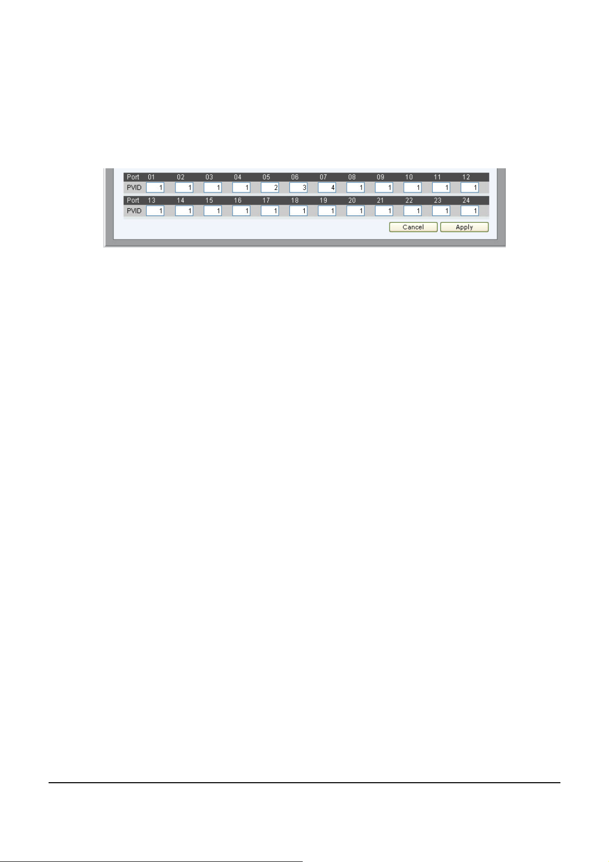
3. Configure the PVID setting located in the bottom of VLAN
configuration page. The user is to set the shared set of ports as PVID 1,
the other separated groups o f ports as PVID 2, 3 and 4.
Figure 355 – Conf i guration > 802.1Q V LAN > Configure PVID
After completing the previous configuration, the user is now able to
share the network resources set on the shared group of ports
(nominated as PVID 1), with both smaller subsets of VLANs
(nominated PVID 2, 3 and 4). Yet, VLAN 2,3 and 4 are incapable of
sharing information with each other and the overlapping VLAN
configuration has been successfully created.
40
Page 45
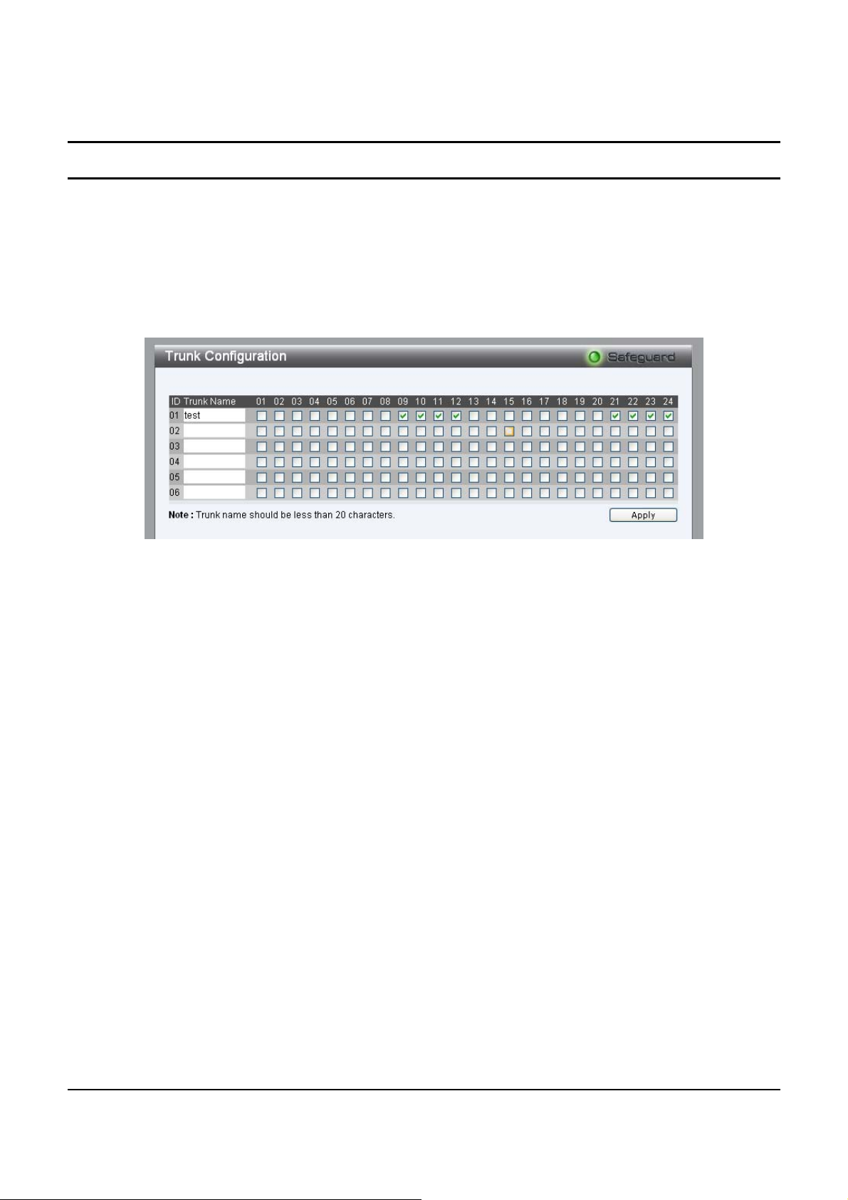
Configuration > Trunking
The Trunking function enables the cascading of two or more ports for
a combined larger bandwidth. Up to six Trunk groups may be created,
each supporting up to 8 ports. Add a Trunking Name and select th e
ports to be trunked together, and click Apply to activate the selected
Trunking groups.
Figure 366 – Configuration > Trunking
NOTE: Each combined trunk port must be connected to devices
within the same VLAN group.
41
Page 46
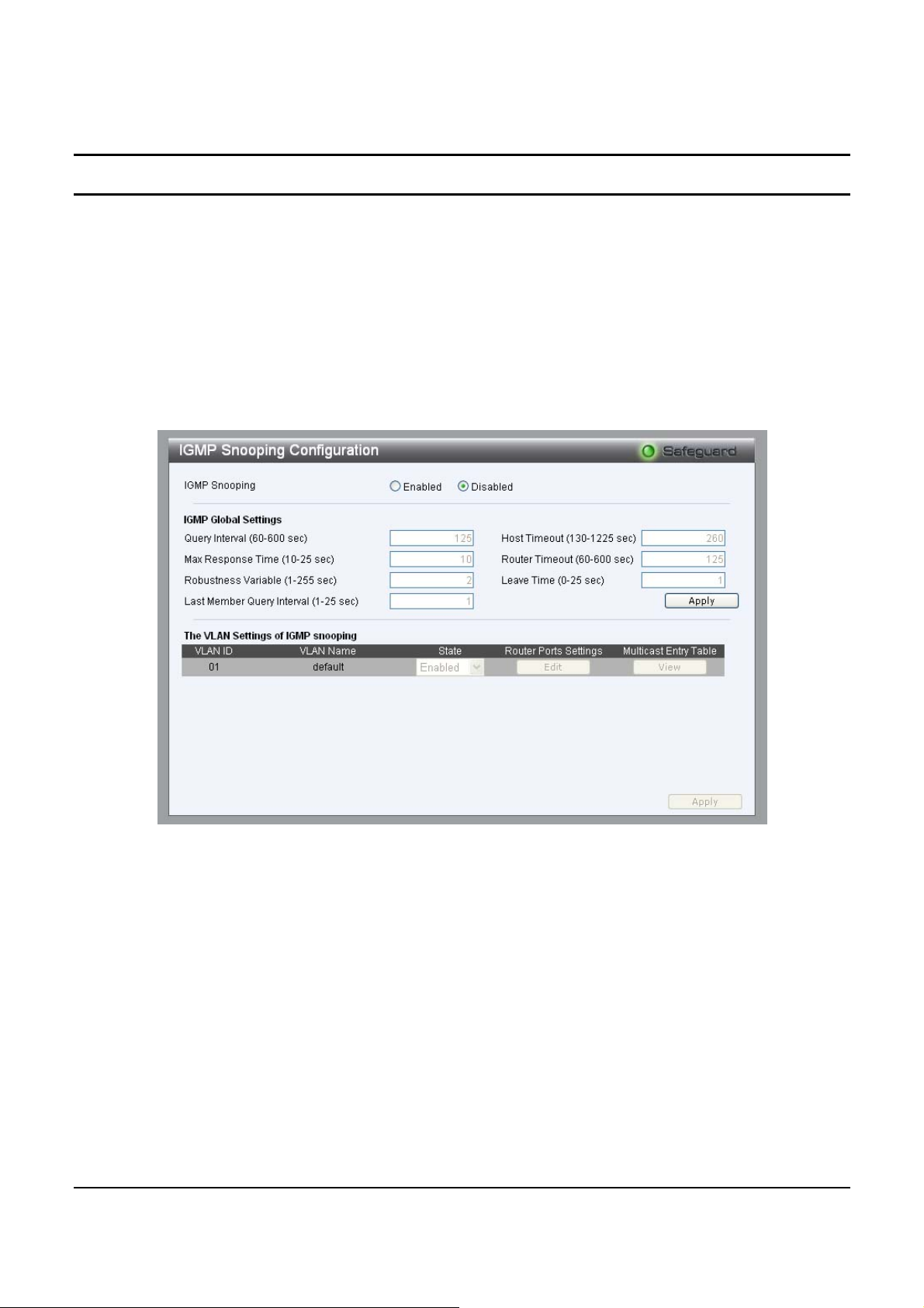
Configuration > IGMP Snooping
With Internet Group Management Protocol (IGMP) snooping, the
Web-Smart Switch can make intelligent multicast forwarding
decisions by examining the contents of each frame’s Layer 3 IP
header. IGMP snooping can help reduce cluttered traf fic on the LAN.
With IGMP snooping enabled globally, the Web-Smart Switch will
forward IP multicast traffic only to connections that have group
members attached.
Figure 377 – Configuration > IGMP Snooping Configuration
By default, IGMP is Disabled. If Enabled, the IGMP Global Settings
will need to be entered:
Query Interval (60-600 sec): The Query Interval is the interval
between General Queries sent. By adjusting the Query Interval, the
number of IGMP messages can increase or decrease; larger values
cause IGMP Queries to be se nt less often. Default is 125 seconds.
42
Page 47

Max Response Time (10-25 sec): The Max Response Time specifies
the maximum allowed time before sending a responding report.
Adjusting this setting effects the "leave latency", or the time between
the moment the last host leaves a group and when the routing protocol
is notified that there ar e no more memb ers. It also allows adjustments
for controlling the frequency of IGMP traffic on a subnet. Default is
10 seconds.
Robustness Variable (1-255 sec): The Robustness Variable allows
adjustment for the expected packet loss on a subnet. If a subnet is
expected to be lossy, the Robustness Variable may be increased. The
Robustness Variable can not be set zero, and SHOULD NOT be one.
Default is 2 seconds.
Last Member Query Interval (1-25 sec): The Last Member Query
Interval is the Max Response Time inserted into Group-Specific
Queries sent in response to Leave Group messages, and is also the
amount of time between Group-Specific Query messages. This value
may be adjusted to modify the "leave latency" of the network. A
reduced value results in reduced time to detect the loss of the last
member of a group. Default is 1 second.
Host Timeout (130-1225 sec): This is th e inte rv al af ter wh ich a learn t
host port entry will be purged. For each host port learnt, a
'PortPurgeTimer' runs for 'HostPortPurgeInterval'. This timer will be
restarted whenever a report message from host is received over that
port. If no report messages are received for 'HostPortPurgeInterval'
time, the learnt host entry will be purged from the multicast group.
Default is 260 seconds.
Router Timeout (60-600 sec): This is th e interv al af ter wh ich a learn t
router port entry will be purged. For each router port learnt, a
'RouterPortPurgeTimer' runs for 'RouterPortPurgeInterval'. This timer
will be restarted whenever a router control message is received over
that port. If no router control messages are received for
43
Page 48
'RouterPortPurgeInterval' time, the learnt router port entry will be
purged. Default is 125 seconds.
Leave Timer (0-25 sec): This is the interval after which a Leave
message is forward ed on a po r t. When a leave message from a host for
a group is received, a group-specific query is sent to the port on which
the leave message is received. A timer is started with a time interval
equal to IgsLeaveProcessInterval. If a report message is received
before above timer expires, the Leave message is dropped. Otherwise
the Leave message is either forwarded to the port. Default is 1 second.
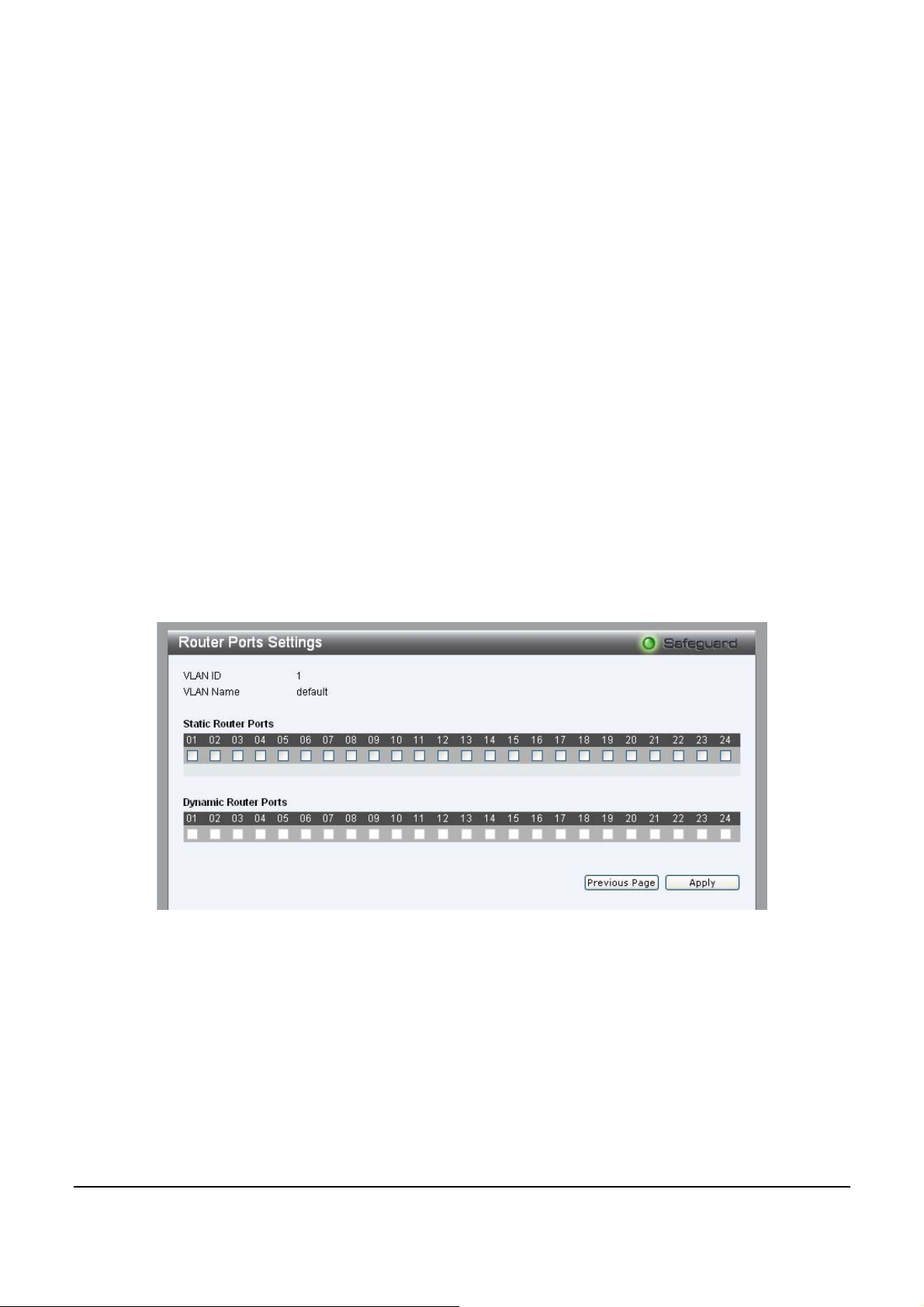
To enable IGMP snooping for a given VLAN, select Enable under
State then press the Edit button under Static Router Port Setting,
then select the por ts to be assign ed for IGMP snoop ing for the VLAN,
and press Apply for changes to take effect.
Figure 388 – Configuration > IGMP Router port Settings
To view the Multicast Entry Table for a given VLAN, press the View
button.
44
Page 49
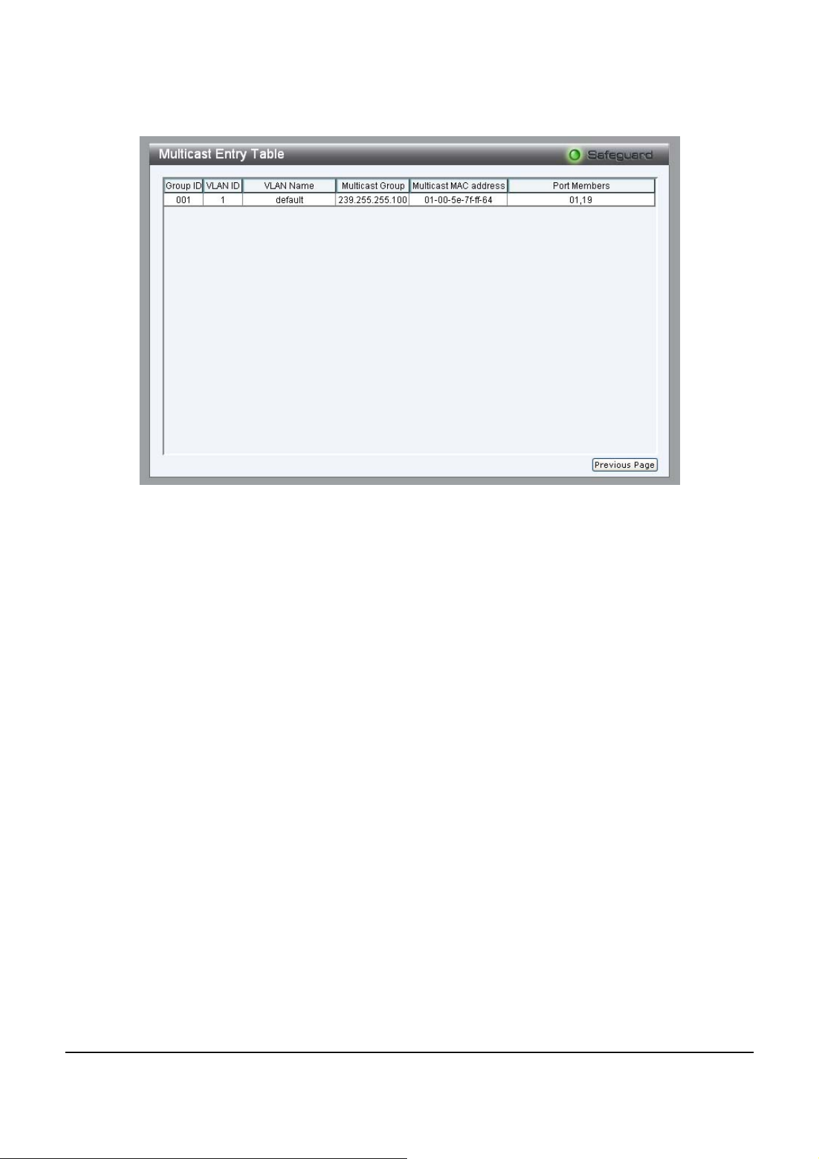
Figure 399 – Configur ation > IGMP Multic as t Entr y Tabl e
45
Page 50
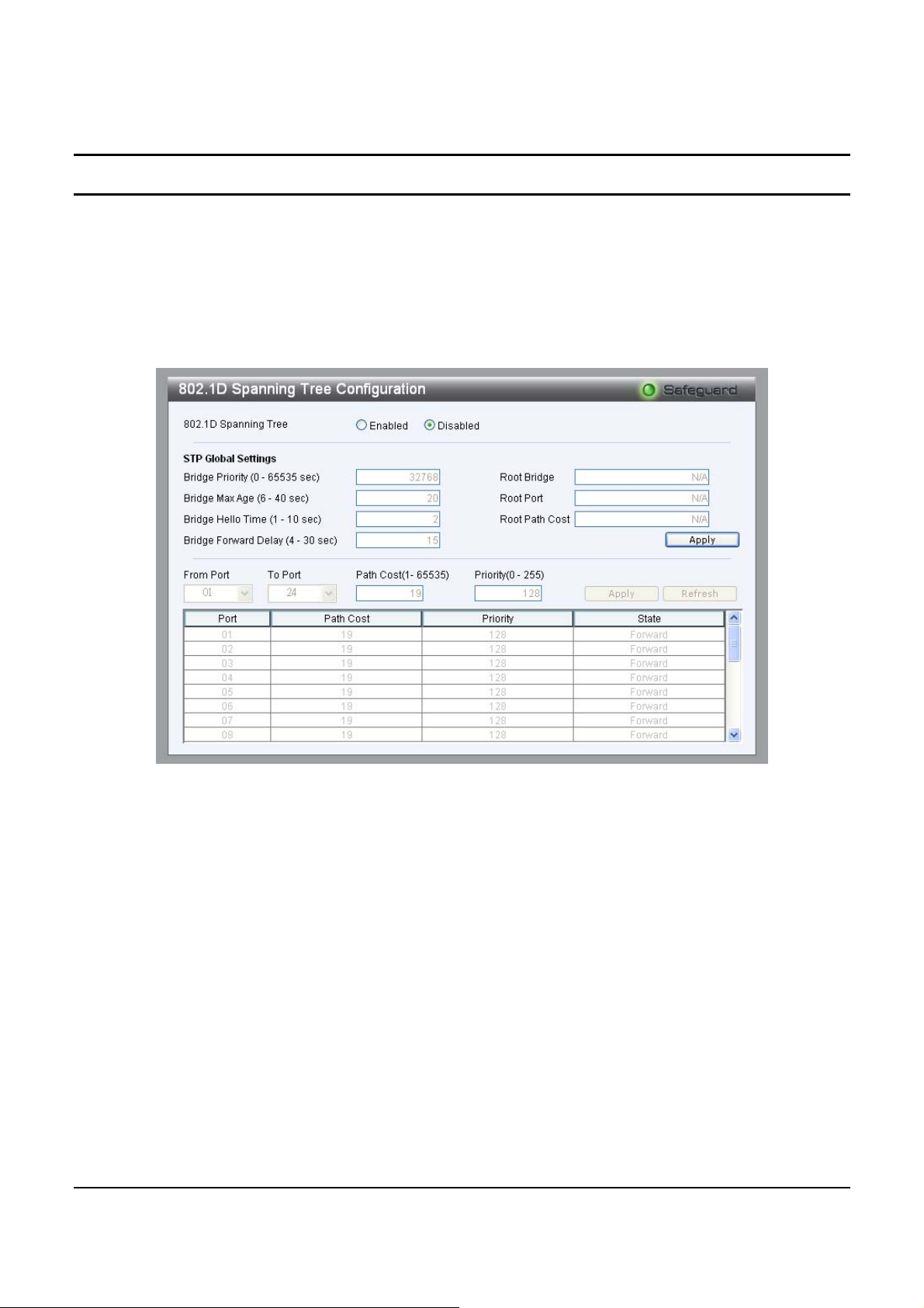
Configuration > 802.1D Spanning Tree
802.1D Spanning Tree Protocol (STP) implementation is designed to
prevent network loops that could cause a broadcast storm. When
physical links forming a loop provide redund ancy, only a single path
will be forwarding frames. If the link fails, STP activates a redundant
link automatically.
Figure 4040 – Configuration > Spanning Tree
By default, Spanning Tree is Disabled. If Enabled, the Switch will
listen for BPDU packets and its accompanying Hello packet. BPDU
packets are sent even if a BPDU packet was not received. Therefore,
each link between bridges is sensitive to the status of the link.
Ultimately this difference resu lts in fas ter detection of f ailed link s, and
thus faster topology adjustment. A draw-back of 802.1D is this
absence of immediate feedback from adjacent bridges.
After Enabling STP, setting the STP Global Setting includes the
following options:
46
Page 51

Bridge Priority: This value between 0 and 65535 specifies the
priority for forwarding packets: the lower the value, the higher the
priority. The default is 32768.
Bridge Max Age: This value may be set to ensure that old
information does not endlessly circulate through redundant paths in
the network, preventing the effective propagation of the new
information. Set by th e Root Bridge, this value will aid in determining
that the Switch has sp anning tree configuratio n values consistent w ith
other devices on the bridged LAN. If the value ages out and a BPDU
has still not been received from the Root Bridge, the Switch will start
sending its own BPDU to all other switc hes for permission to become
the Root Bridge. If it turns out that the Switch has the lowest Bridge
Identifier, it will become the Root Bridge. A time interval may be
chosen between 6 and 40 seconds. The default value is 20.
Bridge Hello Time: The user may set the time interval between
transmissions of configuration messages by the root device, thus
stating that the Switch is still function ing. The default is 2 seconds.
Bridge Forward Delay: This sets the maximu m amount of time that
the root device will wait before changing states. The default is 15
seconds.
Root Bridge: Displays the MAC address of the Root Bridge.
Root port: Displays the root port.
Root Path Cost: Shows the root path cost.
Path Cost: This defines a metric that indicates the relative cost of
forwarding packets to specified port list. The lower the number, the
greater the probability the por t will be chosen to forward packets. The
default value is 19.
47
Page 52
Path Priority: Select a value between 0 and 255 to specify the
priority for a specified port for forwarding packets: the lower the
value, the higher the priority. The default is 128.
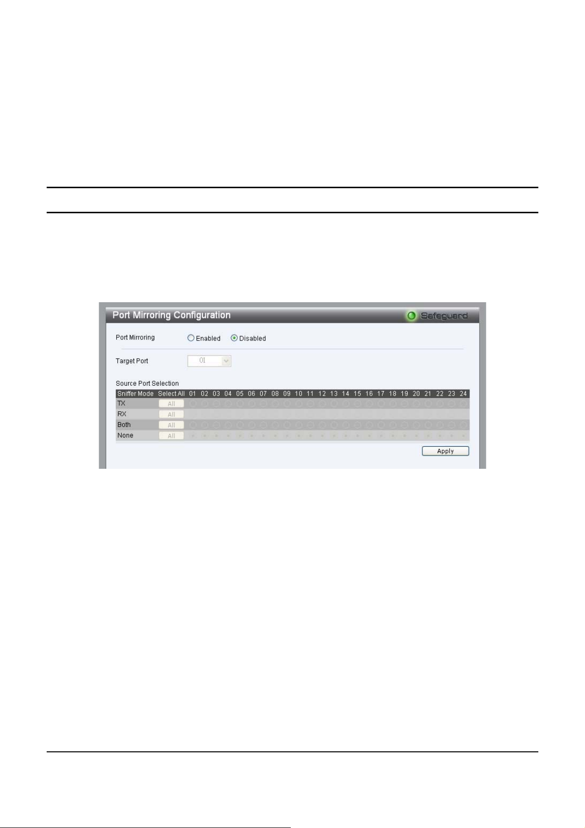
Configuration > Port Mirroring
Port Mirroring is a meth od of monito r ing n etw ork tr aff ic tha t fo rwar d s
a copy of each incoming and/or outgoing p acket from one port of the
Switch to another port where the packet can be studied. This enables
network managers to better monitor network performances.
Figure 4141 – Configuration > Port Mirroring
Selection options for the Source Ports are as follows:
TX (transmit) mode: Duplicates the data transmitted from the source
port and forwards it to the Target Port.
RX (receive) mode: Duplicates the data that send to the source and
forwards it to the Target Port.
Both (transmit and receive) mode: Duplicate both the data
transmitted from and d ata send to the source port, and forward s all the
data to the assigned Target Port.
None: Turns off the mirroring of the port.
48
Page 53
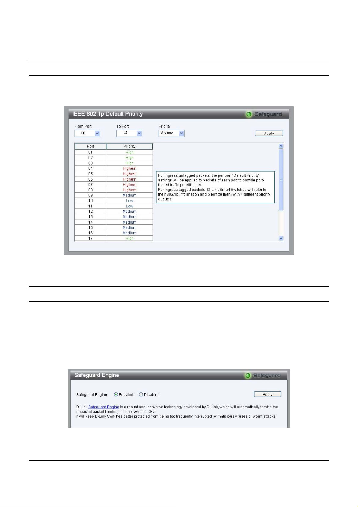
QoS > 802.1p Default Priority
This feature displays the status Quality of Service priority levels of
each port, and for po rts that are Untagged, the priority can be adjusted.
Figure 4242 – QoS > 802.1p Default Priority
Security > Safeguard Engine
By default is Enabled, D-Link’s Safeguard Engine is a robust and
innovative techno logy that au toma tically throttles the impa ct of pack et
flooding into the switch's CPU. This function helps protect the WebSmart Switch from being interrupted by malicious viruses or worm
attacks.
Figure 4343 – Security > Safeguard Engine
49
Page 54
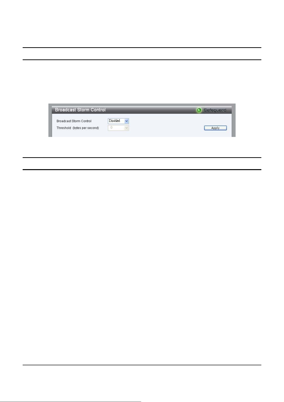
Security > Broadcast St orm Control
The Broadcast Storm Control (BSC) feature provides the ability to
control the receive rate of broadcasted packets. If Enabled (default is
Disabled), threshold settings of 8,000; 16,000; 32,000; 64,000 bytes
per second can be assigned. Press Apply for the settings to take effect.
Figure 444 – Security > Broadcast Storm Control
Security > IP-MAC-Port Bindin g
D-Link DIS-5024T features IP-MAC-Port binding function to
mitigate/prevent ARP spoofing attack. ARP spoofing attack is a
serious threat for the network environment such as network café,
there’re several different forms as below:
(1) The attacker may send broadcast ARP packets with a fake
IP/MAC addresses of the router to paralyze the whole network. A
router or firewall with “Gratuito us ARP” function can prevent it from
happening, but DIS-5024T can have better performance than
router/firewall on it.
(2) The attacker sends a unicast ARP packet with fake IP/MAC
addresses of the router to block a specific PC’s network connection. In
this case, either router or firewall can not provide a protection against
it.
(3) The hacker may combine the attack (2) and forge IP/MAC
addresses of other PCs to become a “Man-in-the-middle” attack. The
traffic of PCs that are deceived will be intercepted by the hacker.
50
Page 55
(4) The hacker forges IP/MAC addresses of a legal user in different
places (ports). Without IP-MAC-Port binding, the administrator can
not find out where the hacker is.
(5) The attacker uses random source MAC ad dr esse s to attack , and th e
administrator can not locate the source in this case.
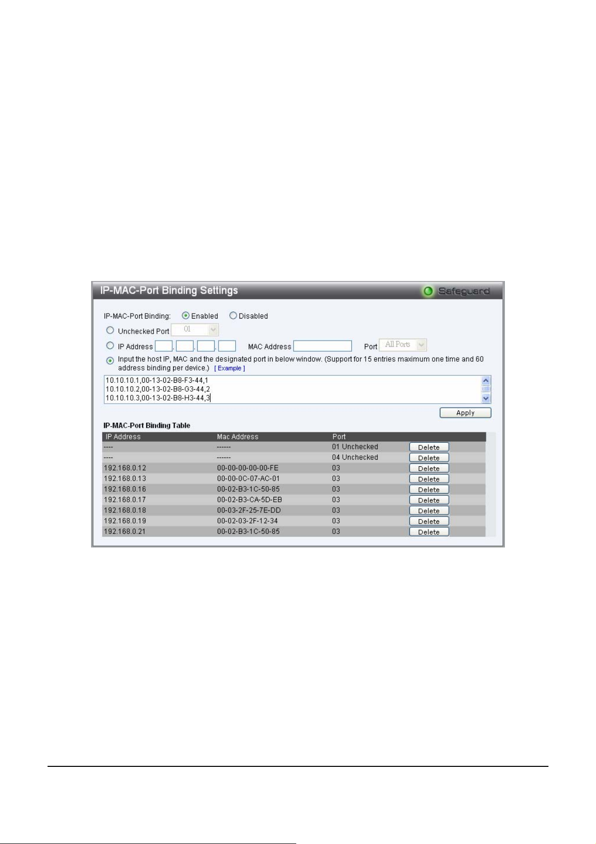
By default, IP-MAC Port Binding is Disabled. To use IP-MAC-Port
Binding for security, select Enabled and set following options.
Figure 455 – Security > IP-MAC-Port Binding Setting
Unchecked Port: The unchecked port is the port for switch to connect
the router (uplink) and IP-MAC-Port binding will not apply to this
port.
DIS-5024T provides two methods to input the entry:
51
Page 56
(i). Manual Input: Enter the IP address, MAC address, and the port(s)
manually, then click “Apply” to establish the database.
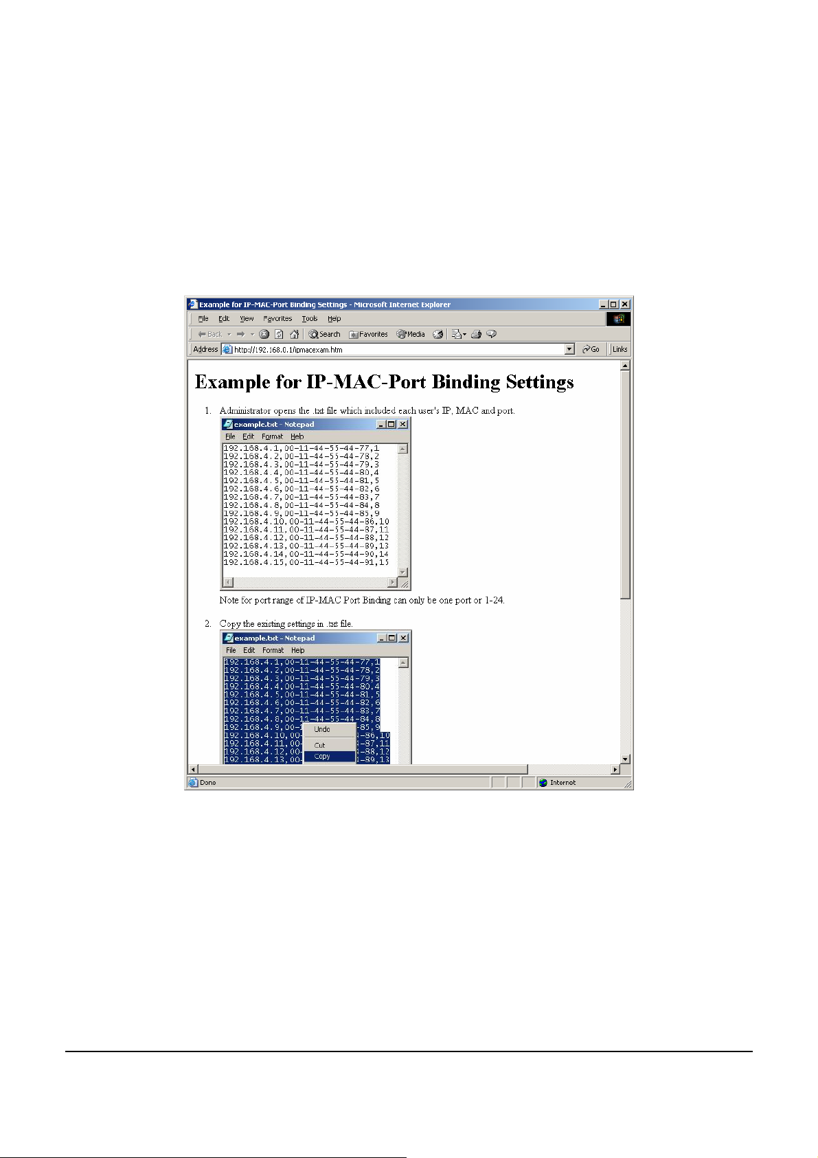
(ii) If the user has a predefined text file, he can easily use copy &
paste to enter the data. Click “Apply” when done.
User can click “Example” to open the page below for reference.
Figure 466 – Security > Example fir IP-MAC-Port Binding Settings
Note: Support for 15 entries maximum one time and 60 address
binding per device.
To Delete an entry, just click “Delete” button in the end of the data.
52
Page 57
Security > 802.1X Setting
IEEE-802.1X provides a security standard for network access control,
predominantly in Wi-Fi wireless networks. 802.1X holds a network
port disconnected until authentication is completed. Depending on the
results, the port is either made available to the user, or the user is
denied access to the network. 802.1X uses the Extensible
Authentication Protocol (EAP) for passing authentication messages.
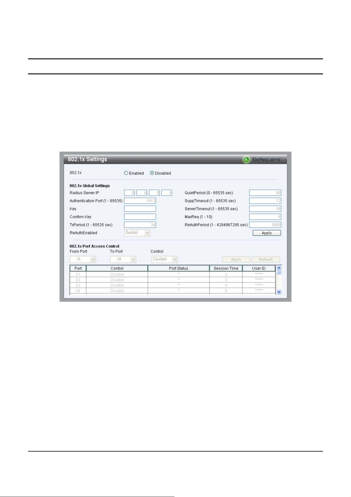
Figure 477 – QoS > 802.1X Se ttin g
By default, 802.1X is Disabled. To use EAP for security, select
Enabled and set the 802.1X Global Settings for the Radius Server and
applicable authentication information.
Authentication Port: sets primary port for security monitoring.
Default is 1812.
Key: Masked password matching the Radius Server Key.
Confirm Key: Enter the Key a second time for confirmation.
53
Page 58

TxPeriod: Sets the number of seconds that the switch waits for a
response to an EAP-request/identity frame from the client before
retransmitting the request. Default is 24 seconds.
ReAuthEnabled: This Enables or Disables the periodic
ReAuthentication control. When the 802.1X function is Enabled, the
ReAuthEnabled fu ncti o n is by defa ul t als o Enabled.
QuietPeriod: Sets the number of seconds that the switch remains in
the quiet state following a failed authentication exchange with the
client. Default 80 seconds
SuppTimeout: Sets the switch-to-client retransmission time for the
EAP-request frame. Default is 12 seconds.
ServerTimeout: Sets the amount of time the switch waits for a
response from the client before resending the response to the
authentication server. Default is 16 seconds.
MaxReq: This parameter specifies the maximum number of times
that the switch retransmits an E AP Request packet to the client before
it times out the authentication session. Default is 5 times.
ReAuthPeriod: This command affects th e beh av ior of th e s witch on ly
if periodic re-authentication is enabled. Default is 3600.
To establish 802.1X port-specific assignments, select the From and
To Ports and select Enable.
54
Page 59
Security > Mac Address Table > Static MAC
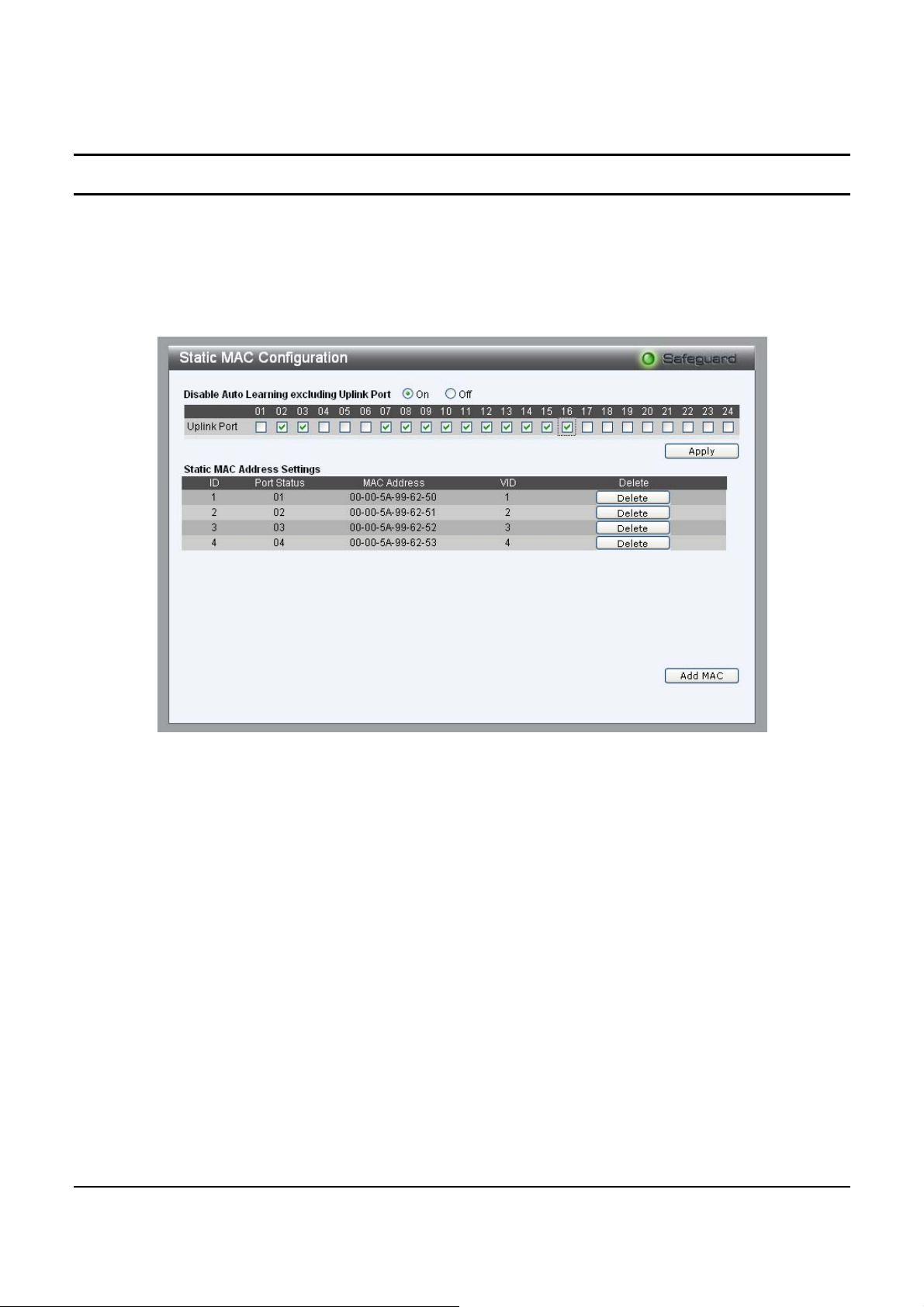
This page provides two distinct features. The top table provides the
ability to turn off auto learning Mac address if a port isn't conn ected to
an uplink Switch (i.e. DHC P Server). By default, this feature is OFF
(disabled).
Figure 488 – Security > Static Mac Address
To initiate the removal of auto-learning for any of the uplink ports,
press On to enab le this feature, and select the port(s) for auto learning
to be disabled.
The Static Mac Address Setting table displays the static Mac
addresses connected, as well as the VID. Press Delete to remove a
device. To add a new Mac address assignment, press Add Mac, then
select the assigned Port number, enter both the Mac Address and VID
and press Apply.
55
Page 60
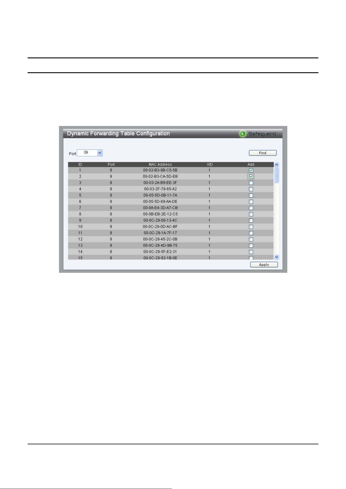
Security > Mac Address Table > Dynamic Forwarding Table
For each port, this table displays the Mac address of each packet
passing through the Switch. To add a Mac address to the Static Mac
Address List, click the Add checkbox associated with the identified
packet.
Figure 499 – Security > Dynamic Forwarding Table
56
Page 61
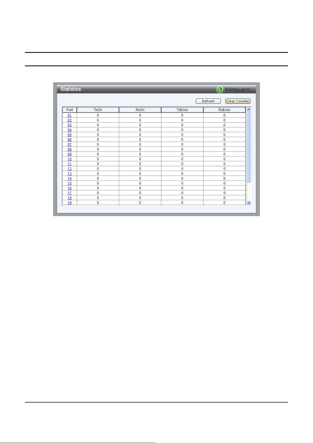
Monitoring > Statistics
The Statistics screen displays the status of each port packet count.
Figure 5050 – Monitori ng > Statis ti cs
Refresh: To renew the details collected and displayed.
Clear Counter: To reset the details displayed.
TxOK: Number of packets transmitted successfully.
RxOK: Number of packets received successfully.
TxError: Number of transmitted packets resulting in error.
RxError: Number of receiv e d pa cke t s resu l t i ng in erro r.
To view the statistics of individual ports, click one of the linked Port
numbers for details.
57
Page 62
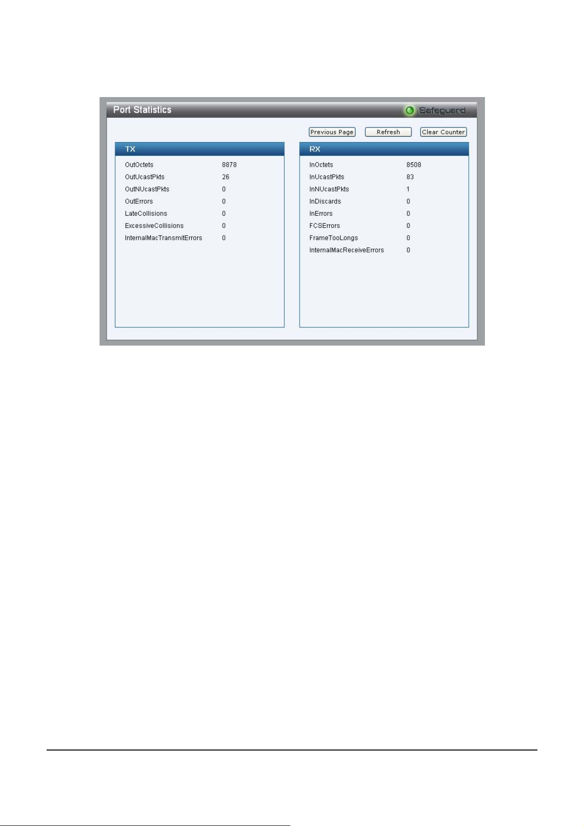
Figure 5151 – Monitoring > Port Statistics
58
 Loading...