

Page 1

D-Link DFL-1500
VPN/Firewall Router
User Manual
D-Link
Building Networks for People
Page 2

© Copyright 2003 D-Link Systems, Inc. All rights reserved.
No part of this public ation including text, examples, diagrams or illustra tions may be reproduced, transmitted, or translated in any
form or by any means, electronic, mechanical, manual, optical or otherwise, for any purpose, without prior writte n permission of
D-Link Systems, Inc.
DFL-1500 User Man ual
Version 0.4
January 30, 2004
Trademarks
Products mentioned in this document are trademarks or registered trademarks of their respective holders.
Regulatory Compliance
FCC Class A Part 15 CSA/CUS
Page 3

I
Table of Contents
Part I Basic Configuration........... ......................................................... .......................................................... 2
Chapter 1 Quick Start ........................................................................................................................................... 3
1.1 Before You Begin................. ................ .............................. ................ ................ ........................................................3
1.2 Check Your Package Contents...................................................................................................................................3
1.3 Default Settings ..........................................................................................................................................................3
1.4 Wiring the DFL-1500 .................................................................................................................................................4
1.5 Default Architecture of DFL-1500.................................................. ................................. ..........................................6
1.6 Using the Setup Wizard......... .. .. .............................. ............................. .............................. ........................................6
1.7 Internet Connectivity..................................................................................................................................................9
1.7.1 LAN1-to-WAN1 Connectivity .........................................................................................................................9
1.7.2 WAN1-to-DMZ1 Connect ivity. .. ... .. .............................. ............................. ....................................................10
Chapter 2 System Overview............................................................................................................................... 13
2.1 Typical Example Topology......................................................................................................................................13
2.2 Changing the LAN1 IP Addr ess.. ... ............................. .............................. ............................. ..................................13
2.2.1 From DMZ1 to configure DFL-1500 LAN1 network settings.... .............................. ............................. .........14
2.2.2 From CLI (command line interface) to configure DFL-1500 LAN1 network settings...................................14
Chapter 3 Basic Setup ........................................................................................................................................ 15
3.1 Demand ....................................................................................................................................................................15
3.2 Objectives.................................................................................................................................................................15
3.3 Methods....................................................................................................................................................................15
3.4 Steps.........................................................................................................................................................................15
3.4.1 Setup WAN1 IP ..............................................................................................................................................16
3.4.2 Setup DMZ1, LAN1 Status.............................................................................................................................17
3.4.3 Setup WAN1 IP alias......................................................................................................................................19
Chapter 4 System Tools...................................................................................................................................... 21
4.1 Demand ....................................................................................................................................................................21
4.2 Objectives.................................................................................................................................................................21
4.3 Methods....................................................................................................................................................................21
4.4 Steps.........................................................................................................................................................................24
4.4.1 General settings...............................................................................................................................................24
4.4.2 DDNS setting... .. ... .. .............................. ........................................................ ..................................................26
4.4.3 DNS Proxy setting ..........................................................................................................................................27
4.4.4 DHCP Relay setting........................................................................................................................................27
4.4.5 Change DFL-1500 inter face ................ ................ ................ .............................. ................ .............................28
4.4.6 SNMP Control ................................................................................................................................................28
Chapter 5 Remote Management ......................................................................................................................... 31
5.1 Demands...................................................................................................................................................................31
5.2 Methods....................................................................................................................................................................31
5.3 Steps.........................................................................................................................................................................32
5.3.1 Telnet..............................................................................................................................................................32
5.3.2 WWW.............................................................................................................................................................32
5.3.3 SNMP .............................................................................................................................................................32
Page 4

II
5.3.4 ICMP .............................................................................................................................................................. 32
Part II NAT、Routing & Firewall .................................................................................................................34
Chapter 6 NAT....................................................................................................................................................35
6.1 Demands...................................................................................................................................................................35
6.2 Objectives.................................................................................................................................................................35
6.3 Methods....................................................................................................................................................................36
6.4 Steps .........................................................................................................................................................................36
6.4.1 Setup Many-to-one NAT rules.......... .. .. .. .............................. .............................. ............................................36
6.4.2 Setup Virtual Server for the FtpServer1 .........................................................................................................40
Chapter 7 Routing...............................................................................................................................................45
7.1 Demands...................................................................................................................................................................45
7.2 Objectives.................................................................................................................................................................45
7.3 Methods....................................................................................................................................................................46
7.4 Steps .........................................................................................................................................................................46
7.4.1 Add a static routing entry........................ ....................................................................... .................................46
7.4.2 Add a policy routing entry.... ................ ......................................................... .................................................47
Chapter 8 Firewall...............................................................................................................................................49
8.1 Demands...................................................................................................................................................................49
8.2 Objectives.................................................................................................................................................................49
8.3 Methods....................................................................................................................................................................49
8.4 Steps .........................................................................................................................................................................50
8.4.1 Block internal PC session (LAN Æ WAN)............... .. ................................................................................... 50
8.4.2 Setup Alert detected attack ............................................................................................................................. 51
Part III Virtual Private Network......................................................................................................................54
Chapter 9 VPN T echnic al Introduction............................. ......... ............ ......... ......... ......... ........... .......................55
9.1 Terminol ogy Explan ation...... ... .... ..... .... ..... .... .. ..... ..... .... ..... .... .. ..... ..... .... ..... .... .. ..... ..... .... ..... ...................................55
9.1.1 VPN................................................................................................................................................................55
9.1.2 IPSec...............................................................................................................................................................55
9.1.3 Security Association ......... .. .. ................ ....................................................................... ...................................55
9.1.4 IPSec Algorithms............................................................................................................................................55
9.1.5 Key Management............................................................................................................................................55
9.1.6 Encapsulation..................................................................................................................................................56
9.1.7 IPSec Protocols...............................................................................................................................................57
9.2 Make VPN packets pass through DFL-1500.............................................. ..............................................................57
Chapter 10 Virtual Private Network – IPSec ......................................................................................................59
10.1 Demands...................................................................................................................................................................59
10.2 Objectives................................................................................................................................................................. 59
10.3 Methods....................................................................................................................................................................59
10.4 Steps.........................................................................................................................................................................60
DES/MD5 IPSec tunnel: the IKE way............................................................................................................60
DES/MD5 IPSec tunnel: the Manual-Key way ..................... ......................................................................... 67
Chapter 11 Virtual Private Network – PPTP.......................................................................................................75
11.1 Demands...................................................................................................................................................................75
11.2 Objectives................................................................................................................................................................. 75
11.3 Methods....................................................................................................................................................................75
Page 5

III
11.4 Steps.........................................................................................................................................................................76
11.4.1 Setup PPTP Network Server.............. .. ... ................ ................ ............... .............................. ...........................76
11.4.2 Setup PPTP Network Client .. .. .. .. .............................. ............................. .............................. ...........................77
Chapter 12 Virtual Private Network – L2TP........................................... ........................................................... 79
12.1 Demands...................................................................................................................................................................79
12.2 Objectives.................................................................................................................................................................79
12.3 Methods....................................................................................................................................................................79
12.4 Steps.........................................................................................................................................................................80
12.4.1 Setup L2TP Network Server............ .. .. ... .. .............................. ............................. ...........................................80
Part IV Content Filters ................ ... ......................................................... ........................................................ 84
Chapter 13 Content Filtering – Web Filters........................................................................................................ 85
13.1 Demands...................................................................................................................................................................85
13.2 Objectives.................................................................................................................................................................86
13.3 Methods....................................................................................................................................................................86
13.4 Steps.........................................................................................................................................................................87
Chapter 14 Content Filtering – Mail Filters....................................................................................................... 93
14.1 Demands...................................................................................................................................................................93
14.2 Objectives.................................................................................................................................................................93
14.3 Methods....................................................................................................................................................................93
14.4 Steps for SMTP Filters.............................................................................................................................................94
14.5 Steps for POP3 Filters ..............................................................................................................................................95
Chapter 15 Content Filtering – FTP Filtering .................................................................................................... 97
15.1 Demands...................................................................................................................................................................97
15.2 Objectives.................................................................................................................................................................97
15.3 Methods....................................................................................................................................................................97
15.4 Steps.........................................................................................................................................................................98
Part V Intrusion Detection System .............................................................................................................. 100
Chapter 16 Intrusion Detection Systems.......... ... ....................................... ..................................... ................. 101
16.1 Demands.................................................................................................................................................................101
16.2 Objectives...............................................................................................................................................................101
16.3 Methods..................................................................................................................................................................101
16.4 Steps.......................................................................................................................................................................102
Part VI Bandwidth Management................................................................................................................... 104
Chapter 17 Bandwidth Management................................................................................................................ 105
17.1 Demands.................................................................................................................................................................105
17.2 Objectives...............................................................................................................................................................106
17.3 Methods..................................................................................................................................................................106
17.4 Steps.......................................................................................................................................................................107
17.4.1 Inbound Traffic Management....................... ............................................................... .................................107
17.4.2 Outbound Traffic Management........ .. ... ............................. .............................. ............................ .................111
Part VII System Maintenance..................................................................................................................114
Chapter 18 System Status..................................................................................................................................115
18.1 Demands.................................................................................................................................................................115
18.2 Objectives...............................................................................................................................................................115
18.3 Methods..................................................................................................................................................................115
Page 6

IV
18.4 Steps....................................................................................................................................................................... 115
Chapter 19 Log System..................................................................................................................................... 117
19.1 Demands.................................................................................................................................................................117
19.2 Objectives...............................................................................................................................................................117
19.3 Methods..................................................................................................................................................................117
19.4 Steps....................................................................................................................................................................... 117
19.4.1 System Logs...... .. .............................. ............................. .............................. .................................................117
19.4.2 Syslog & Mail log.......................... .............................. ............................. ....................................................118
Chapter 20 System Maintenance .................. ... ..................... ............................................................................ 119
20.1 Demands.................................................................................................................................................................119
20.2 Steps for TFTP Upgrade...... ................ ................ ................ ............................. ................ ......................................119
20.3 Steps for Firmware upgrade from Web GUI.......................................................................................................... 121
20.4 Steps for Factory Reset........................................................................................................................................... 121
20.4.1 Steps for NORMAL factory reset................................................................................................................. 121
20.4.2 Steps for EMERGENT factory reset.............................................................................................................121
20.5 Steps for Backup / Restore Configurations ............................................................................................................122
Appendix A Command Line Interface (CLI) .. ... ...........................................................................................123
A.1 Enable the port of DFL-1500................................. ...........................................................................123
A.2 CLI commands list............................................................................................................................123
Appendix B Trouble Shooting.......................................................................................................................125
Appendix C Packet Flow...... ... ........................................................................... ..................... ......................129
Appendix D Glossary of Terms.....................................................................................................................131
Appendix E Index ................ .........................................................................................................................133
Appendix F Hardware.......... ...... ...... ... ...... ...... ... ...... ...... ... ...... ...... ... ...... ...... ... ...... ...... ... ...... .........................135
Appendix G Version of Software and Firmware ...........................................................................................137
Appendix H Customer Support ..... ... ....................................... ......................................................................139
Page 7

Page 8

D-Link Part I
2
Part I
Basic Configuration
Page 9
Quick Start DFL-1500 User Manual
3
Chapter 1
Quick Start
This chapter introduces how to quick setup the DFL-1500.
DFL-1500 is an integrated all-in-one solution that can facilitate the maximum security and the best resource utilization for
the enterprises. It contains a high-performance stateful packet inspection (SPI) Firewall, policy-based NAT, ASIC-based
wire-speed VPN, upgradeable Intrusion Detection System, Dynamic Routing, Content Filtering, Bandwidth
Management, W AN Load Balancer, and other solutions in a single box. It is one of the most cost-effective all-in-one
solutions for enterprises.
1.1 Before You Begin
Prepare a computer with an Ethernet adapter for configuring the DFL-1500. The default IP address for the DFL-1500 is
192.168.1.254 (LAN1, Port 4) with a Subnet Mask of 255.255.255.0. You will need to assign your computer a Static IP
address within the same range as the DFL-1500’s IP address, say 192.168.1.2, to configure the DFL-1500.
1.2 Check Your Package Contents
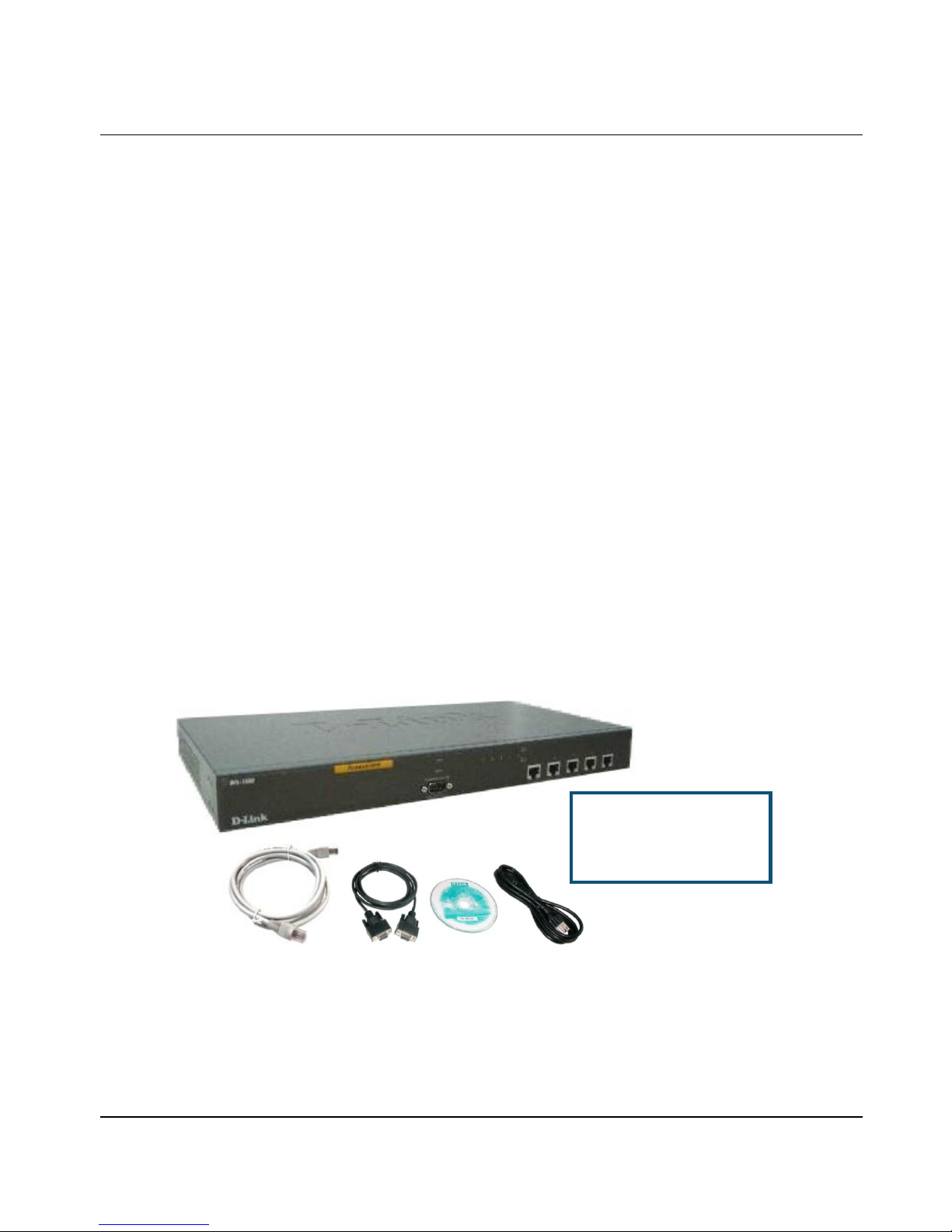
These are the items included with your DFL-1500 purchase as Figure 1-1. They are the following items
1. DFL-1500 Device * 1
2. Ethernet cable (RJ-45)
3. RS-232 console * 1
4. CD (include User's manual and Quick Guide) * 1
5. Power code * 1
Figure 1-1 All items in the DFL-1500 package
1.3 Default Settings
You should have an Internet account already set up and have been given most of the following information as Table 1-1.
Fill out this table when you edit the web configuration of DFL-1500.
If any of the items are
missing, please contact your
reseller.
Page 10

D-Link Part I
4
Items Default value New value
Password: admin
IP Address ____.____.____.____
Subnet Mask ____.____.____.____
Gateway IP ____.____.____.____
Primary DNS ____.____.____.____
Fixed IP
Secondary DNS ____.____.____.____
PPPoE Username ____.____.____.____
PPPoE
PPPoE Password ____.____.____.____
WAN1
(Port 1)
DHCP
Not init ia li zed
IP Address ____.____.____.____
Subnet Mask ____.____.____.____
Gateway IP ____.____.____.____
Primary DNS ____.____.____.____
Fixed IP
Secondary DNS ____.____.____.____
PPPoE Username ____.____.____.____
PPPoE
PPPoE P asswor d
____.____.____.____
WAN2
(Port 2)
DHCP
Not init ia li zed
IP Address 10.1.1.254 ____.____.____.____
DMZ1(Port 3)
IP Subnet Mask 255.255.255.0 ____.____.____.____
IP Address 192.168.1.254 ____.____.____.____
LAN1(Po r t 4)
IP Subnet Mask 255.255.255.0 ____.____.____.____
IP Address 192.168.2.254 ____.____.____.____
LAN2(Po r t 5)
IP Subnet Mask 255.255.255.0 ____.____.____.____
Table 1-1 DFL-1500 related n etwor k sett ings
1.4 Wiring the DFL-1500
A. First, connect the power cord to the socket at the back panel of the DFL-1500 as in Figure 1-2 and
then plug the other end of the power adapter to a wall outlet or power strip. The Power LED will turn ON
to indicate proper operation.
A. Power Socket
Page 11
Quick Start DFL-1500 User Manual
5
Figure 1-2 Back panel of the DFL-1500
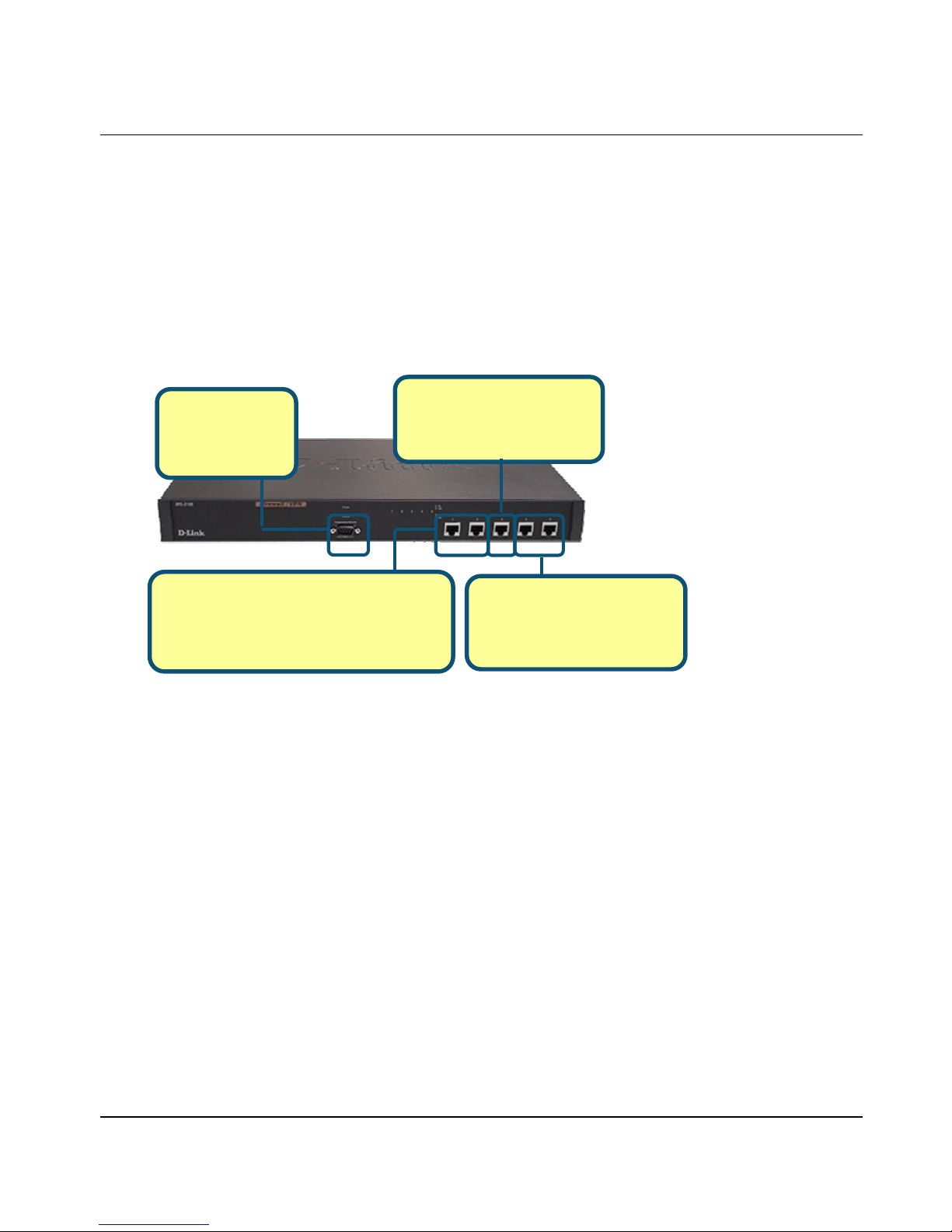
B. Using an Ethernet cable, insert one end of the cable to the W AN port on the front panel of t he DFL-1500
and the other end of the cable to a DSL or Cable modem, as in Figure 1-3.
C. Computers with an Ethernet adapter can be directly connected to any of the LAN ports using a
cross-over Ethernet cable, as in Figure 1-3.
D. Computers that act as servers to provide Internet services should be connected to the DMZ port using an
Ethernet Cable, as in Figure 1-3.
\
Figure 1-3 Front end of the DFL-1500
C. LAN Ports
For connecting computers and
network devices to your LAN.
Left to right: LAN1, LAN2
Console Port
For managing the
DFL-1500 with CLI
commands.
B. WAN Ports
For connecting the DFL-1500 to a DSL or
Cable Modem supplied by your ISP to access
the Internet. Left to right: WAN1, WAN2
D. DMZ Port
For connecting computers that
act as servers for Internet
users to access.
Page 12
D-Link Part I
6
1.5 Default Architecture of DFL-1500
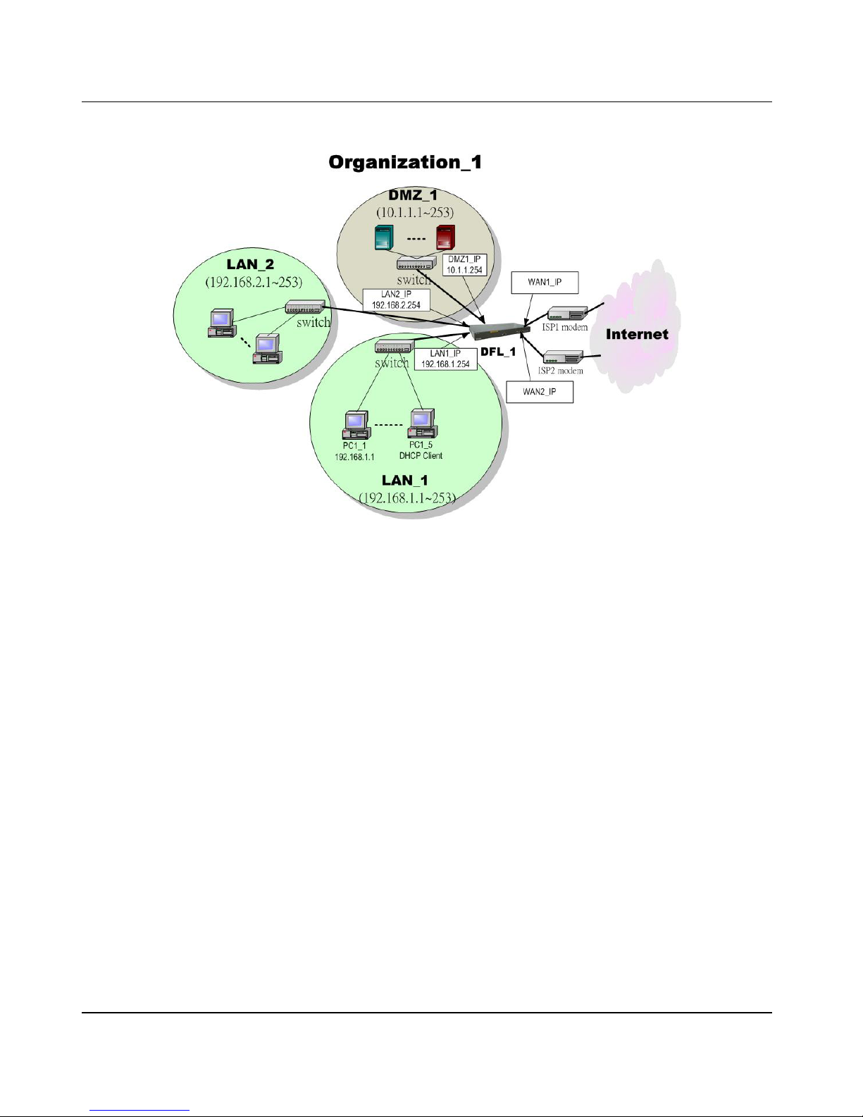
Figure 1-4 The defa ult settings of DFL-1500
The factory default settings for the DFL-1500 are in the Figure 1-4 and Table 1-1. You can configure the DFL-1500 by
connecting to the LAN1_IP (192.168.1.254) from the PC1_1 (192.168.1.1). The following section will teach you how to
quickly setup the DFL-1500 based on Figure 1-4.
1.6 Usi ng the Setup Wizard
A computer on your LAN1 must be assigned an IP address and Subnet Mask from the same range as the IP address and
Subnet Mask assigned to the DFL-1500 in order to be able to make an HTTPS connection using a web browser. The
DFL-1500 is assigned an IP address of 192.168.1.254 with a Subnet Mask of 255.255.255.0 by default. The computer
that will be used to configure the DFL-1500 must be assigned an IP address between 192.168.1.1 and 192.168.1.253
with a Subnet Mask of 255.255.255.0 to be able to connect to the DFL-1500. This address range can be changed later.
There are instructions in the DFL-1500 Quick Installation Guide, if you do not know how to set the IP address and Subnet
Mask for your computer.
Page 13
Quick Start DFL-1500 User Manual
7
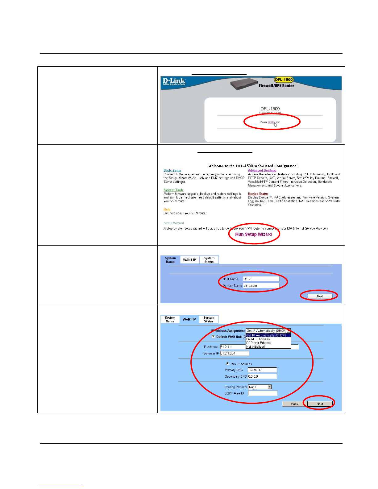
Step 1 - Login
Type “admin” in the account field, “admin” in the
Password field and click Login.
Connect to https://192.168.1.254
Step 2 - Run Setup Wizard
Click the Run Setup Wizard.
After login to https://192.168.1.254
BASIC SETUP > Wizard
Step 3 - System Name
Enter the Host Name and the Domain Name,
followed by clicking the Next.
BASIC SETUP > Wizard
Step 4 - WAN Connectivity
To setup the first WAN link, make WAN1 as the
Default WAN link (Gateway/DNS). Choose
the type of IP Address Assignment provided by
your ISP to access the Internet. Here we have four
types to select. This will determine how the IP
address of WAN1 is obtained. Click Next to
proceed.
BASIC SETUP > Wizard > Next
Page 14
D-Link Part I
8
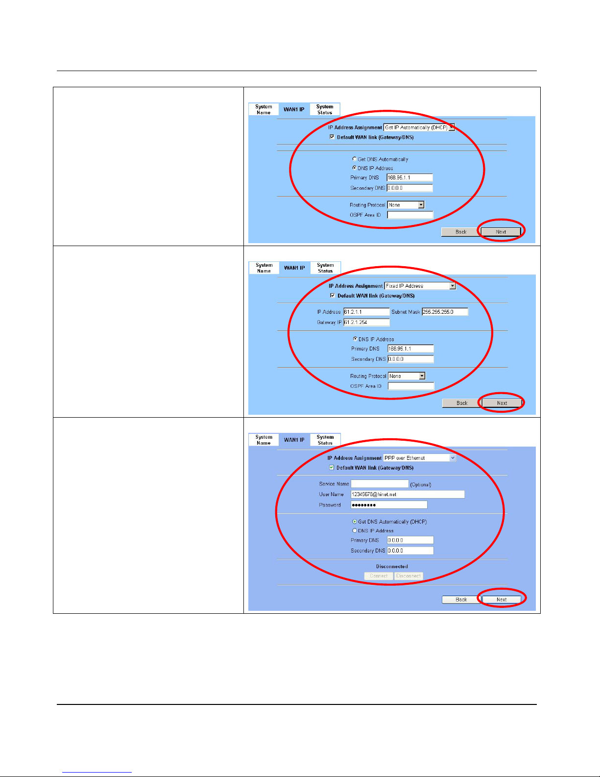
Step 4. a — DHCP client
If Get IP Automatically (DHCP) is selected,
DFL-1500 will request for IP address, netmask,
and DNS servers from your ISP. You can use your
preferred DNS by clicking the DNS IP Address
and then completing the Primary DNS and
Secondary DNS server IP addresses. Click Next
to proceed.
BASIC SETUP > Wi zard > Next > DHCP
Step 4.b — Fixed IP
If Fixed IP Address is selected, enter the
ISP-given IP Address, Subnet Mask, Gateway
IP, Primary DNS and Secondary DNS IP. Click
Next to proceed.
BASIC SETUP > Wizard > Next > Fixed IP
Step 4. c — PPPoE client
If PPP over Ethernet is selected, enter the
ISP-given User Name, Password and the optional
Service Name. Click Next to proceed.
Notice: On the current firmware version, if you
select PPPoE method a s the WAN li nk con nect ion .
The bandwidth management feature will not be
supported.
BASIC SETUP > Wizard > Next > PPPoE
Page 15
Quick Start DFL-1500 User Manual
9
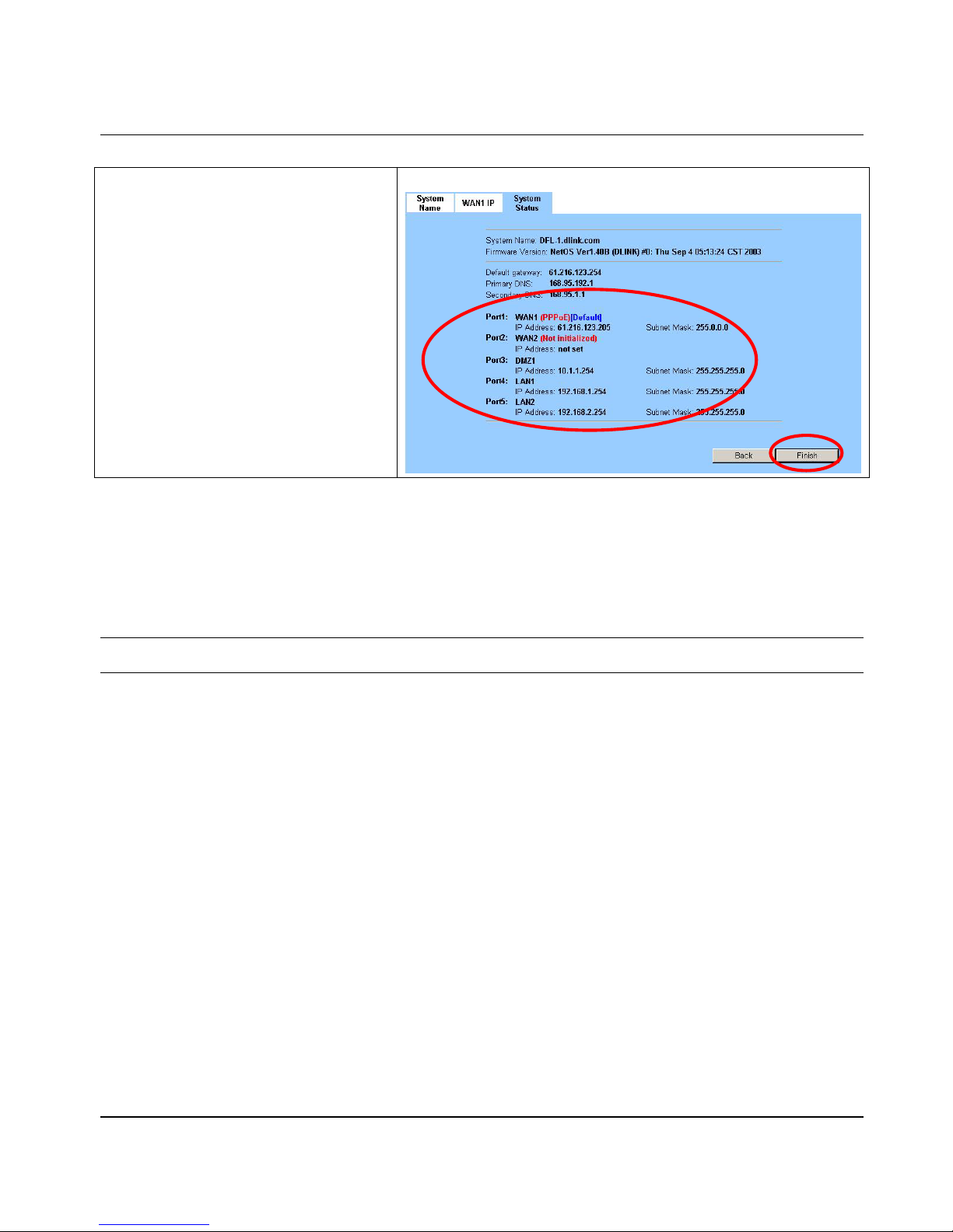
Step 5 - System Status
Here we select PPPoE method in WAN1 port. Then
the DFL-1500 provides a short summary of the
system. Please check i f any t hing m enti oned a bove
is properly set into the system. Click Finish to
close the wizard.
BASIC SETUP > Wizard > Next > Next
1.7 Internet Connectivity
After setting up DFL-1500 with the wizard, DFL-1500 can connect to the ISP. In this chapter, we introduce LAN1-to-WAN1
Connectivity to explain how the computers under LAN1 can access the Internet at WAN1 through DFL-1500. Subsequently, we
introduce WAN1-to-DMZ1 Connectivity to explain how the servers under DMZ1 can be accessed by the LAN1 users and other
Internet us ers on the W AN1 sid e .
You MUST press Apply to proceed to the next page. Once applying any changes, the settings are immediately
updated into the flash memory.
1.7.1 LAN1-to-WAN1 Connectivity
The LAN Settings page allows you to modify the IP address and Subnet Mask that will identify the DFL-1500 on your LAN. This is
the IP address you will enter in the URL field of your web browser to connect to the DFL-1500. It is also the IP address that all of
the computers and devices on your LAN will use as their Default Gateway.
Page 16
D-Link Part I
10
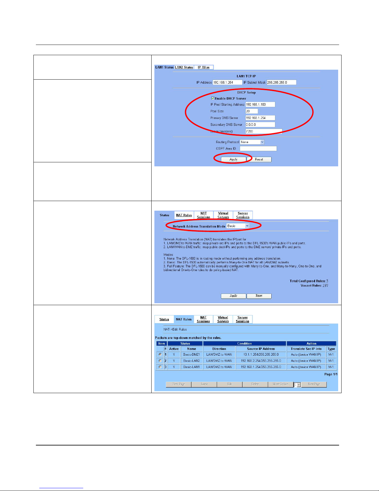
Step 1 - Device IP Address
Setup the IP Address and IP Subnet Mask for
the DFL-1500.
Step 2 - Client IP Range
Enable the DHCP server if you want to use
DFL-1500 to assign IP addresses to the
computers under LAN1. Specify the Pool
Starting Address, Pool Size, Primary DNS,
and Secondary DNS that will be assigned to
them.
Example: in the figure, the DFL-1500 will assign
one IP address from 192.168.1.100 ~
192.168.1.120, together with the DNS server
192.168.1.254, to the LAN1 PC that requests
for an IP address.
Step 3 - Apply the Changes
Click Apply to save. Now you can enable the
DHCP clients on your LAN1 PCs to get an IP.
BASIC SETUP > LAN Settings > LAN1 Status
Note: The IP Pool Starting Address must be on the same subnet specified
in the IP Address and the IP Subnet Mask field. For example, the addresses
given by the 192.168.1.100 with a pool size of 20 (192.168.1.100 ~
192.168.1.120) are all within the same range of 192.168.1.254 /
255.255.255.0
Step 4 - Check NAT Status
The default setting of NAT is in Basic Mode.
After completing Step 3, the NAT is automatically
configured with three rules to let all private-IP
LAN/DMZ-to-WAN requests to be translated with
the public IP assigned by the ISP.
ADVAN C E D SETTIN G S > N AT > S t atus
Step 5 - Check NAT Rules
The DFL-1500 has added three NAT rules. The
rule Basic-LAN1 (number 3) means that, when
matching the condition (requests of
LAN/DMZ-to-WAN direction with its source IP
falling in the range of 192.168.1.254 /
255.255.255.0), the request will be translated
into a public-source-IP requests, and then be
forwarded to the destinations.
ADVANCED SETTINGS > NAT > NAT Rules
1.7.2 WAN1-to-DMZ1 Connectivity
This section tells you how to provide an FTP service with a server installed under your DMZ1 to the public Internet users. After
following the steps, users at the WAN side can connect to the FTP server at the DMZ1 side.
Page 17
Quick Start DFL-1500 User Manual
11
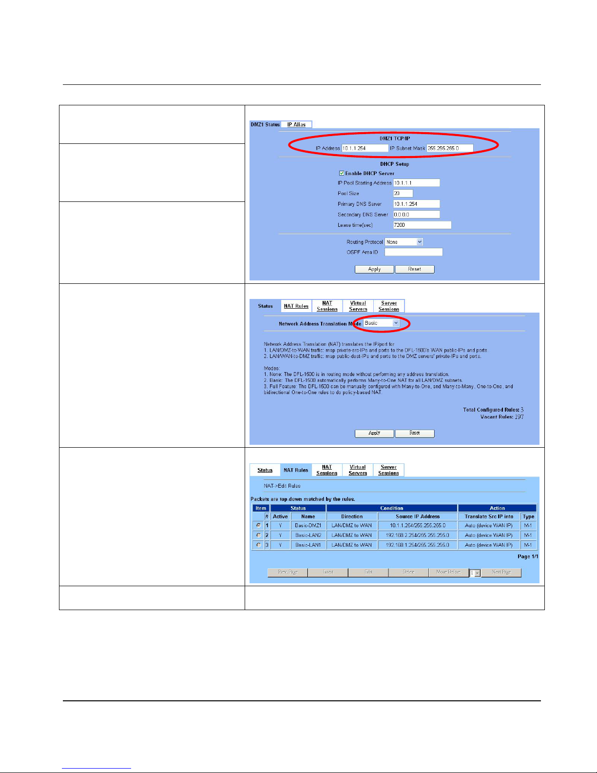
Step 1 - Device IP Addres s
Setup the IP Address and IP Subnet Mask for
the DFL-1500 of the DMZ1 i nterface.
Step 2 - Client IP Range
Enable the DHCP server if you want to use
DFL-1500 to assign IP addresses to the
computers under DMZ1. Here we do not enable
DHCP feature.
Step 3 - Apply the Changes
Click Apply to save your settings.
BASIC SETUP > DMZ Settings > DMZ1 Status
Step 4 - Check NAT Status
The default setting of NAT is in Basic Mode.
After applying the Step 3, the NAT is
automatically configured with three rules to let all
private-IP LAN/DMZ-to-WAN requests to be
translated with the public IP assigned by the ISP.
ADVANCED SETTI NGS > NAT > Status
Step 5 - Check NAT Rules
The DFL-1500 has added three NAT rules. The
rule Basic-DMZ1 (number 1) means that, when
matching the condition (requests of
LAN/DMZ-to-WAN direction with its source IP
falling in the range of 10.1.1.254 /
255.255.255.0), the request will be translated
into a public-source-IP requests, and then be
forwarded to the destinations.
ADVANCED SETTI NGS > NAT > NAT Rules
Step 6 - Setup IP for the FTP Server
Assign an IP of 10.1.1.5/255.255.255.0 to the FTP server under DMZ1. Assume
the FTP Server is at 10. 1.1.5. And it is listening on the well-known port (21).
Page 18
D-Link Part I
12
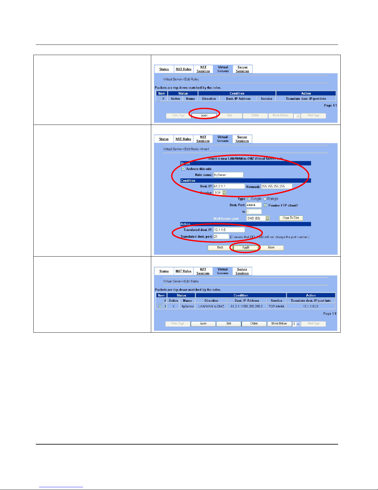
Step 7 - Setup Server Rules
Insert a virtual server rule by clicking the Insert
button.
ADVANCED SETTINGS > NAT > Virtual Servers
Step 8 - Customize the Rule
Customize the rule name as the ftpServer. For
any packets with its destination IP address
equaling to the WAN1 IP (61.2.1.1) and
destination port equaling to 44444. DFL-1500 will
translate the packet’s destination IP/port into
10.1.1.5/21. Check the Passive FTP client
to maximize the compatibility of the FTP protocol.
This is useful i f you want to pr ovi d e conn e cti vi ty to
passive FTP clients. For passive FTP clients, the
server at DMZ will return them the private IP
address (10.1.1.5) and the port number for the
clients to connect back for data transmissions.
Since the FTP clients at the WAN side cannot
connect to a private-IP (ex.10.1.1.5) through the
internet. The data connections would be fail. A fter
enabling this feature, the DFL-1500 will translate
the private IP/port into an IP/port of its own. Thus
the problem is gracefully solved. Click Apply to
proceed.
ADVANCED SETTINGS > NAT > Virtual Servers > Insert
Step 9 - View the Result
Now any request towards the DFL-1500’s WAN1
IP (61.2.1.1) with dest. port 44444 will be
translated into a request towards 10.1.1.5 with
port 21, and then be forwarded to the 10.1.1.5.
The FTP server listening at port 21 in 10.1.1.5
will pick up the request.
ADVANCED SETTINGS > NAT > Virtual Servers
Page 19

System Overvi ew DFL-1500 User Manual
13
Chapter 2
System Overview
In this chapter, we will introduce the network topology for use with later chapters.
2.1 Typical Example Topology
In this chapter, we introduce a typical network topology for the DFL-1500. In Figure 2-1, the left half side is a DFL-1500 with one
LAN, one DMZ, and two WAN links. Notice ther e are five ports in DF L-1500. In this top ology, we only use one LAN.
The right half side contains a DFL-1500 connected with one LAN, one DMZ, and one WAN. In this architecture, Organization_1
communicates with Organization_2 with a VPN tunnel established by the two DFL-1500 Firewall/VPN routers. The VPN tunnel
secures communications between Organizations more safely.
On the Internet side, there are Web server, Mail server, DHCP server, and FTP server for testing the content filters and the
bandwidth managemen t sy stem .
Figure 2-1 Typica l topology for deploying DFL-1500
2.2 Changing the LAN1 IP Address
The default settings of DFL-1500 are listing in Table 1-1. However, the original LAN1 setting is 192.168.1.254/255.255.255.0
instead of 192.168.40.254/255.255.255.0 as in Figure 2-1. We will change the LAN1 IP of the DFL-1500 to 192.168.40.254. Notice
that you cannot change the LAN1 IP from the LAN1 interface because your configuration session to LAN1 will be terminated as
long as the LAN1 IP address is changed. If you do change the IP from the LAN1 port, you will have to reboot the system, change
your computer’s IP to the new subnet, and reconnect to the new LAN1 IP address. You can also use console to login into the system
Page 20
D-Link Part I
14
and then logout the system. That will clean up the zombie left in the system so you will be able to login to the DFL-1500 from the
LAN1 side after your computer’s IP is changed into the new subnet.
We provide two normal ways to configure the LAN1 IP address. One is to configure the LAN1 IP from another port such as DMZ1
or LAN2. The other is to configure the LAN1 IP through console. Note that when setting the IP address from console, the settings
are updated into run-time system but not stored into the flash. Namely, the setting s will be lost after y ou reboot the system. So, it is
best to use the first method for setting the LAN1 IP address.
2.2.1 From DMZ1 to configure DFL-1500 LAN1 network settings
Step 1 - Check NAT Status
In the DMZ_1 region, use a PC located 10.1.1.X
to connect DFL-1500 DMZ1 port (10.1.1.254).
Type https://10.1.1.254
to configure the
DFL-1500 in the web browser.
Use an IE 6.0 at 10.1.1.1 to connect to https://10.1.1.254
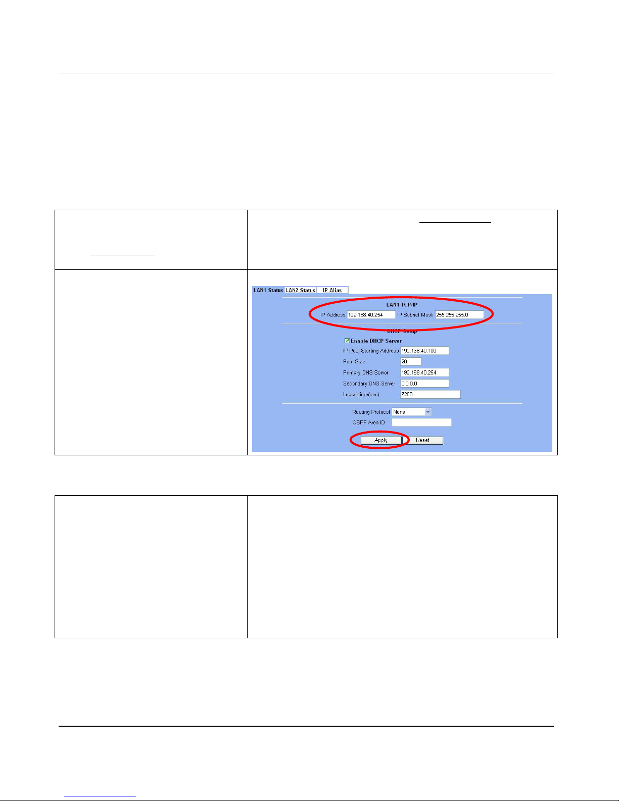
Step 2 - Setup LAN1 IP information
Enter the IP Address and IP Subnet Mask with
192.168.40.254 / 255.255.255.0 and click
Apply.
BASIC SETUP > LAN Settings > LAN1 Status
2.2.2 From CLI (command line interface) to configure DFL-1500 L AN1 network settings
Step 1 - Use Console p ort to configure
DFL-1500
Use the supplied console line to connect the PC
to the Diagnostic RS-232 socket of the DFL-1500.
Start a new connection using the HyperTerminal
with parameters: No Parity, 8 Data bits, 1
stop bit, and baud rate 9600. Enter admin
for user name and admin for password to login.
After logging into DFL-1500, enter the commands
“en“ to enter the privileged mode. Enter the
command “ip ifconfig INTF3
192.168.40.254 255.255.255.0” to change
the IP of the LAN1 interface.
DFL-1500> en
DFL-1500# ip ifconfig INTF3 192.168.40.254 255.255.255.0
DFL-1500# ip ifconfig INTF3
====== ======== =============== =============== ====== =============
Port Interface IP Address Netmask Status Type
------ -------- --------------- ---------------- ------- ------------ 4 LAN1 192.168.40.254 255.255.255.0 UP
====== ======== =============== =============== ======= =============
Page 21

Basic Setup DFL-1500 User Manual
15
Chapter 3
Basic Setup
In this chapter, we will introduce how to setup network settings for each port separately
3.1 Demand
1. For the external network, suppose your company uses DSL to connect Internet via PPPoE. By this way, you should setup
WAN port of the DFL-1 5 00 in advance.
2. There are some adjustment within your company, so the original network stucture has been changed. Now, you should
modify the configuration between the internal network (DMZ, LAN).
3. Your company needs more network bandwidth if it is insufficent for your company to connect to the external network.
3.2 Objectives
1. Configure the network settings of the DFL-1500 WAN1 port.
2. Configure the network settings of the DFL-1500 DMZ1 and LAN1 ports.
3. Suppose your company applys another ISP, and hope that the applied Network IP can configure in the same WAN port of
DFL-1500.
3.3 Methods
1. Select the PPPoE method in the DFL-1500 Basic Setup/WAN settings/WAN1 IP, and then configure the related account
and password in order to connet to the internet.
2. Configure the related network settings in the pages of the DFL-1500 Basic Setup / DMZ settings / DMZ1 Status、Basic
Setup / LAN settings / LAN1 Status.
3. Configure the IP a lias in WAN1 port.
3.4 Steps
Notice:Do not try to configure the port network setting from the same port you login. Or the network will be terminated and system
will be locked in the original IP address.
Page 22

D-Link Part I
16
3.4.1 Setup WAN1 IP
Step 1 - Setup WAN1 port
Here we select Fixed IP Address method in
WAN1 port. Fill in the IP Address, Subnet
Mask, Gateway IP. And then enter the other
DNS IP Address, Routing Protocol fields.
Click Apply to fini sh this setting.
BASIC SETUP > WAN Settings > WAN1 IP > Fix e d IP Address
IP Address
Assignment
FIELD DESCRIPTION EXAMPLE
Default WAN link
(Gateway/DNS)
When Default WAN link is enabled. All the packets
sent out from DFL-1500 will be via this port.
Enabled
Get DNS Automatically or
DNS IP Address
Get DNS Automatically Æ Get DNS related
information from DHCP Server
DNS IP Address Æ manually specify these Primary
and Secondary DNS Server information
Get DNS
Automatically
Routing Protocol
Determine to enable the dynamic routing protocol, to
receive RIP message, to send out the RIP message if the
RIP message is received or not.
None
Get IP
Automatically
(DHCP)
OSPF Area ID Specify OSPF area ID number
Default WAN link
When Default WAN link is enabled. All the packets
sent out from DFL-1500 will be via this port.
Enabled
IP Address / Subnet Mask Specified IP address and subnet mask
61.2.1.1
255.255.255.0
Gateway IP Default gateway IP address 61.2.1.254
DNS IP Address Specified Primary and Secondary DNS Server address 168.95.1.1
Routing Protocol
Determine to enable the dynamic routing protocol, to
receive RIP message, to send out the RIP message if the
RIP message is received or not.
None
Fixed IP
Address
OSPF Area ID Specify OSPF area ID number
Default WAN link
When Default WAN link is enabled. All the packets
sent out from DFL-1500 will be via this port.
Enabled
Service Name ISP vendor (Optional) So-Net
User Name The user name of PPPoE account Hey
PPP over
Ethernet
Password The password of PPPoE account G54688
Page 23
Basic Setup DFL-1500 User Manual
17
Get DNS Automatically /
DNS IP Address
Get DNS Automatically Æ Get DNS related
information from PPPoE ISP
DNS IP Address Æ manually specify these Primary
and Secondary DNS Server information
Get DNS
Automatically
Disconnected
Through click Connect or Disconnect button to connect
or disconnect PPPoE line
Click Connect
Table 3-1 Detailed information of se tup WAN port configur ation
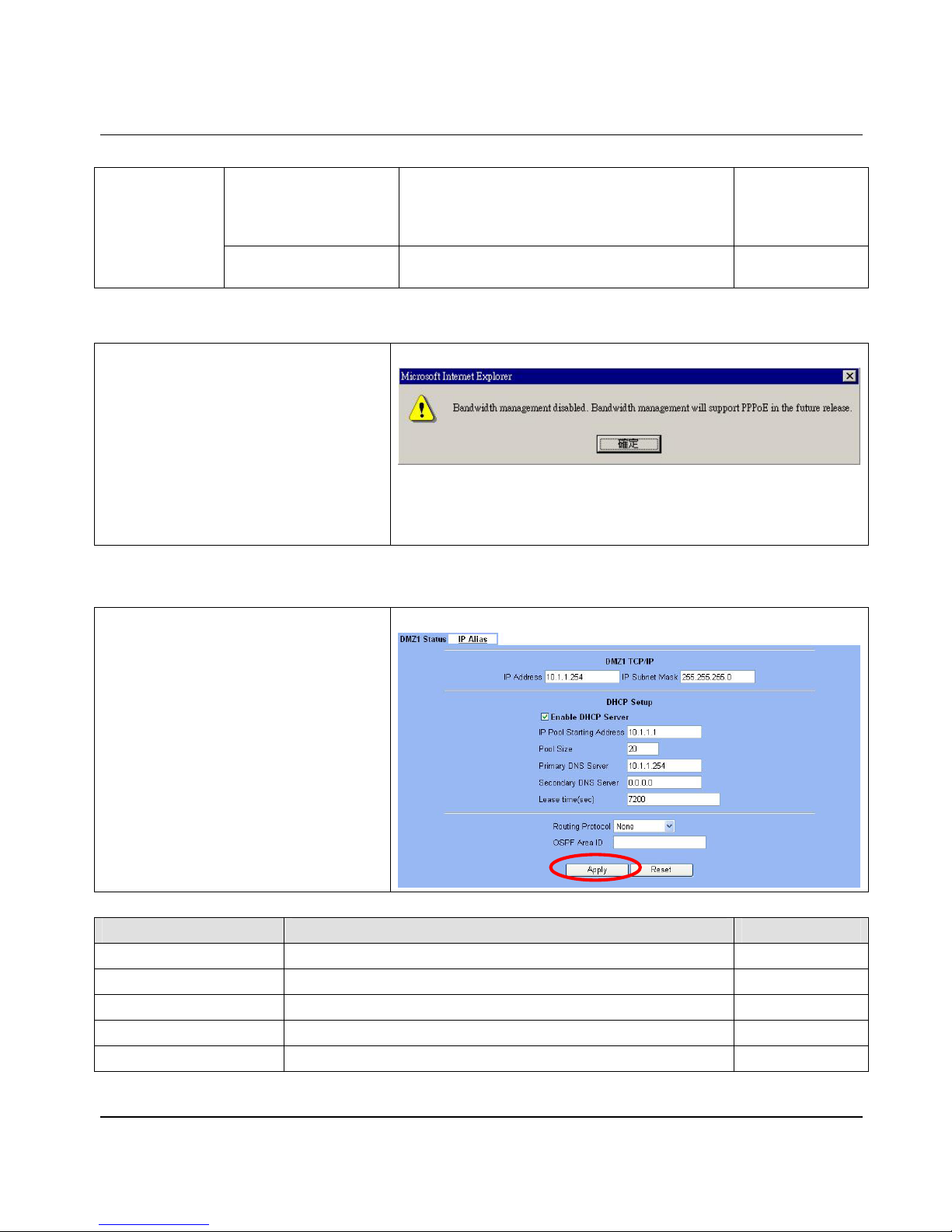
Step 2 - Show the Warning message
Note that if you have alr eady enabled
bandwidth management (ADVANCED
SETTINGS>Bandwidth Mgt>E nabl e Bandwi dth
Management) and then select PPPoE in BASIC
SETUP>WAN Settings>WAN1 IP>PPPoE as
your internet connection, it will show you a
message indicated as right column to tell you that
Bandwidth management will not support PPPoE
in this version. If you still like to us e bandwidth
management, please try to use another method,
such as DHCP or Fixed IP, to connect Internet.
BASIC SETUP > WAN Settings > WAN1 IP > PPPoE
3.4.2 Setup DMZ1, LAN1 Status
Step 1 - Setup DMZ port
Here we are going to con fi gure the DMZ1
settings. Setup IP Address and IP Subnet
Mask, and determine if you would like to enable
the DHCP Server. And then select Routing
Protocol. Click Apply to finish this setting.
BASIC SETUP > DMZ Settings > DMZ1 Status
FIELD DESCRIPTION EXAMPLE
IP Address DMZ port IP address 10.1.1.254
IP Subnet Mask DMZ port IP subnet m ask 255.255.255.0
Enable DHCP Server Enable DMZ port of the DHCP Sever or not Enabled
IP Pool Starting Address Specify the starting address of the DHCP IP address. 10.1.1.1
Pool Size Specify the numbers of the DHCP IP address. 20
Page 24
D-Link Part I
18
Primary DNS Server Specify the Primary DNS Server IP address of the DHCP information. 10.1.1.254
Secondary DNS Server Specify the Secondary DNS Server IP address of the DHCP information.
Lease time(sec) Specify DHCP information lease ti me 7200
Routing Protocol
Determine to enable the dynamic routing protocol (RIP), to receive RIP
message, to send out RIP message if the message is received or not.
None
OSPF Area ID Specify OSPF area ID number
Table 3-2 Configure DMZ network setting s
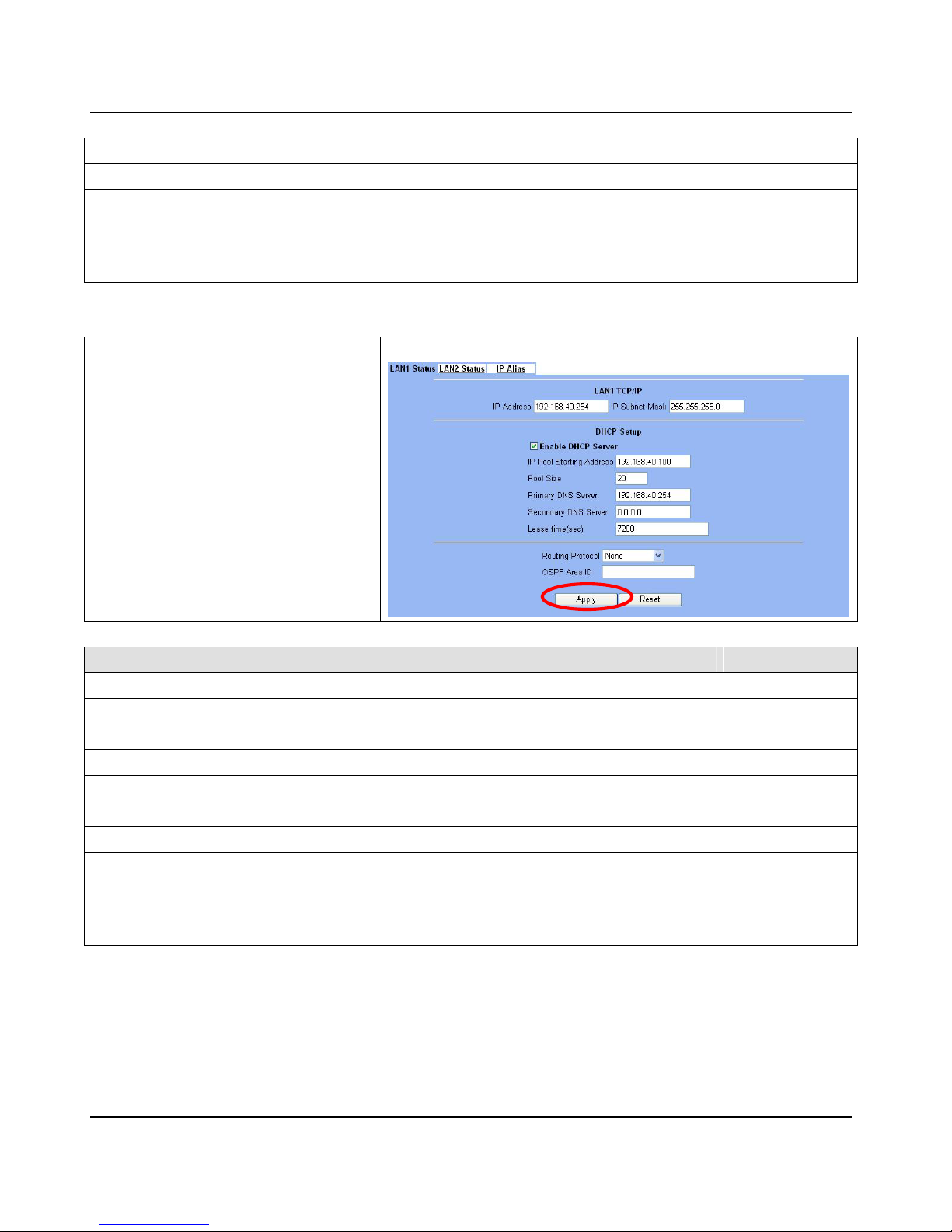
Step 2 - Setup LAN port
Here we are going to configur e the LAN 1 sett ings.
Setup IP Address and IP Subnet Mask, and
determine if you would like to enable the DHCP
Server. And then select Routing Protocol. Click
Apply to finish this setting.
BASIC SETUP > LAN Settings > LAN1 Status
FIELD DESCRIPTION EXAMPLE
IP Address LAN port IP add re ss 192.168.40.254
IP Subnet Mask LAN port IP subnet mask 255.255.255.0
Enable DHCP Server Enable LAN port of the DHCP Sever or not Enabled
IP Pool Starting Address Specify the starting address of the DHCP IP address. 192.168.40.100
Pool Size Specify the numbers of the DHCP IP address. 20
Primary DNS Server Specify the Primary DNS Server IP address of the DHCP information. 192.168.40.254
Secondary DNS Server Specify the Secondary DNS Server IP address of the DHCP information.
Lease time(sec) Specify DHCP information lease ti me 7200
Routing Protocol
Determine to enable the dynamic routing protocol (RIP), to receive RIP
message, to send out RIP message if the message is received or not.
None
OSPF Area ID Specify OSPF area ID number
Table 3-3 Configur e LAN network settings
Page 25
Basic Setup DFL-1500 User Manual
19
3.4.3 Setup WAN1 IP alias
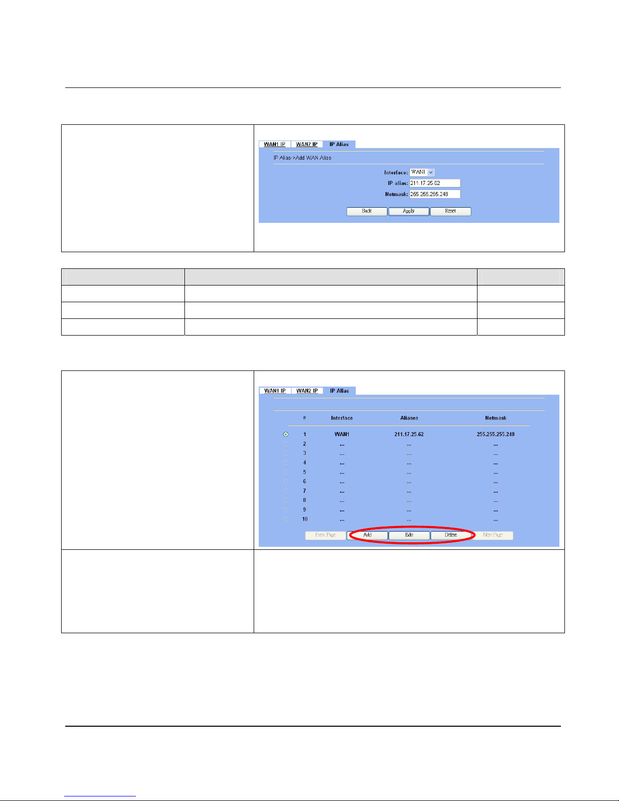
Step 1 - Add WAN1 IP alias
Suppose you apply 8 IP addresses from ISP. The
range of the ISP-given IP address is fro m
211.17.25.56 to 211.17.25.63. Now you would
like to add a WAN1 IP alias. Select WAN1 in the
Interface. Enter the IP alias and Netmask with
211.17.25.62/255.255.255.248. And then click
Apply.
Notice:It’s the sam e way to set IP ali as in DMZ or
LAN.
BASIC SETUP > WAN Settings > IP Alias > Add
FIELD DESCRIPTION EXAMPLE
Interface The interface which we set for the IP alias WAN1
IP alias The alias IP address
211.17.25.62
Netmask The netmask of the IP alias 255.255.255.248
Table 3-4 Add a IP alias record
Step 2 - Edit, Delete IP a lias record
You can easily add, edit, or delete IP alias
records by the Add, Edit, or Delete button.
BASIC SETUP > WAN Settings > IP Alias
Step 3 - Add a static or policy routing
entry
Refer to the Chapter 7 ex planation.
In the “Advanced Settings > Routing” pages, setup the static or
policy routing pages to share the outbound traffic load.
Page 26

Page 27

Syste m Tools DFL-1500 User Manual
21
Chapter 4
System Tools
This chapter introduces System Management and explains how to implement it.
4.1 Demand
1. Basic configurations for domain name, password, system time, timeout and services.
2. DDNS: Suppose the DFL-1500’s WAN uses dynamic IP but needs a fixed host name. When the IP is changed, it is
necessary to have the DNS record updated accordingly. To use this service, one has to register the account, password, and
the wanted host name with the service provider.
3. DNS Proxy: Shorten the time of DNS look up performed by applic ations.
4. DHCP Relay: It is to s olve the problem that when the DHCP client is not in the same domain with the DHCP server, the
DHCP broadcast will not be received by the server. If the client is in the LAN (192.168.40.X) while the server is located in
the DMZ (10.1.1.10), the server will not receive any broadcast packet from the client.
5. Suppose our company applies three ISPs, but there are ju st two default WAN ports in the DFL-1500. Y ou hope to connect
the whole ISP links to the DFL-1500.
6. The System Administrator would like to monitor the device from remote side efficiently.
4.2 Objectives
1. Configure the ge neral properties, such as domain name, password, system time, and connection timeout correctly. Besides,
we can configure the prefered service name as the service name/numeric mapping list.
2. DDNS: By using the DDNS (Dynamic DNS), the DFL-1500 will send the request for modifi cation of the cor responding
DNS record to the DDNS server after the IP is changed.
3. DNS Proxy: Reduce the number of DNS requests and the time for DNS lookup.
4. DHCP Relay: Enable the DHCP client to contact with the DHCP server located in different domain and get the required IP.
5. We hope to customize the interface of DFL-1500 to fit our requests.
6. Through the SNMP manager, we can easily monitor the device status.
4.3 Methods
1. Configure the domain name, password, system time, connection timeout and service name.
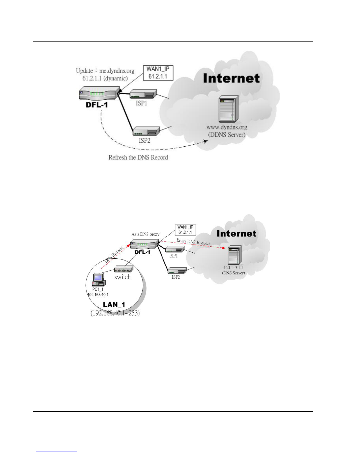
2. DDNS: Configure the DFL-1500 so that whenever the IP of the DF L-1500 is changed, i t will send requests to the DDNS
server to refresh the DNS record. As the following Figure 4-1 demonstrated, the original DFL-1 has registered WAN1 ip
address “61.2.1.1” on the DDNS server (www.dyndns.org) . It’s domain name address is “me.dyndns.org”. If the WAN1 ip
address is reassigned by the ISP. DFL-1 will update the registered ip address “61.2.1.1” as the assigned one. This is the
base mechanism of the DDNS.
Page 28
D-Link Part I
22
Figure 4-1 DDNS mechanism chart
3. DNS Proxy: After activating the DNS proxy mode, the client can set its DNS server to the DFL-1500 (that is, send the DNS
requests to the DFL-1500). The DFL-1500 will then make the enquiry to the DNS ser ver and return the result to the client.
Besides, the caching mechanism performed by the DNS proxy can also help reduce possible duplicate DNS lookups. As the
following Figure 4-2 described. DFL-1 redirects the DNS request from PC1_1 to the real DNS server (140.113.1.1).
Figure 4-2 DNS Proxy mechanism chart
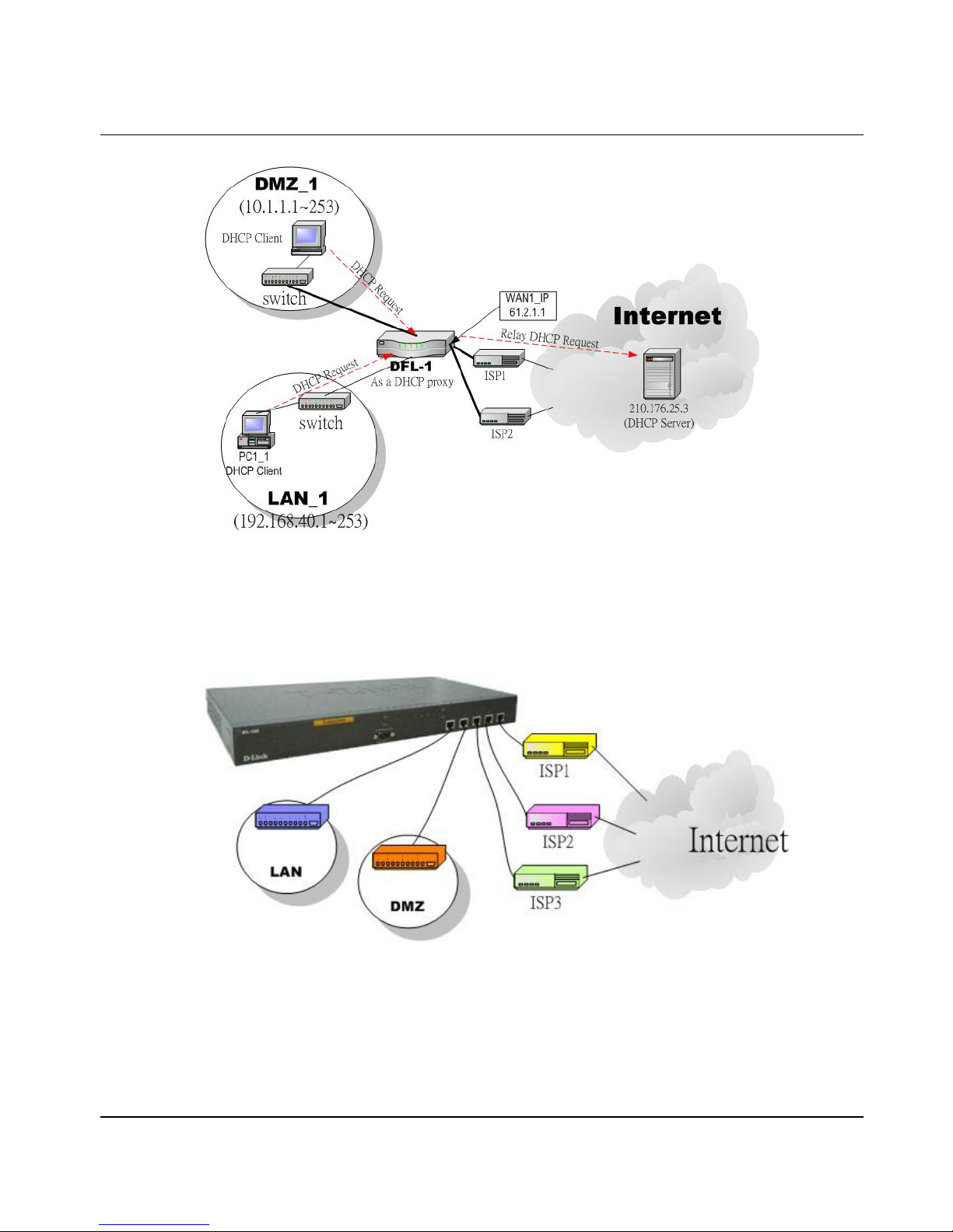
4. DHCP Relay: Activate the DHCP relay mode of DFL-1500 so that the DFL-1500 will become the relay agent and relay the
DHCP broadcast to th e configured DHCP server. As the following Figure 4-3 described, DFL-1 redirects the DHCP request
from the preconfigured port (LAN1, DMZ1) to the real DHCP server (210.176.25.3).
Page 29
Syste m Tools DFL-1500 User Manual
23
Figure 4-3 DHCP Relay mechanism chart
5. We can adjust the DFL-1500 interface in the SYSTEM TOOLS > Admin Settings > Interface in according to our
preference and requirement (3 WAN, 1 LAN, 1 DMZ). As the following Figure 4-4 demonstrated, there are three ISP
connected onto DFL-1500. So we must adjust the interface up to 3 WAN port s to fit the current condition.
Figure 4-4 Adjust DFL-1500 interface to fit present situation
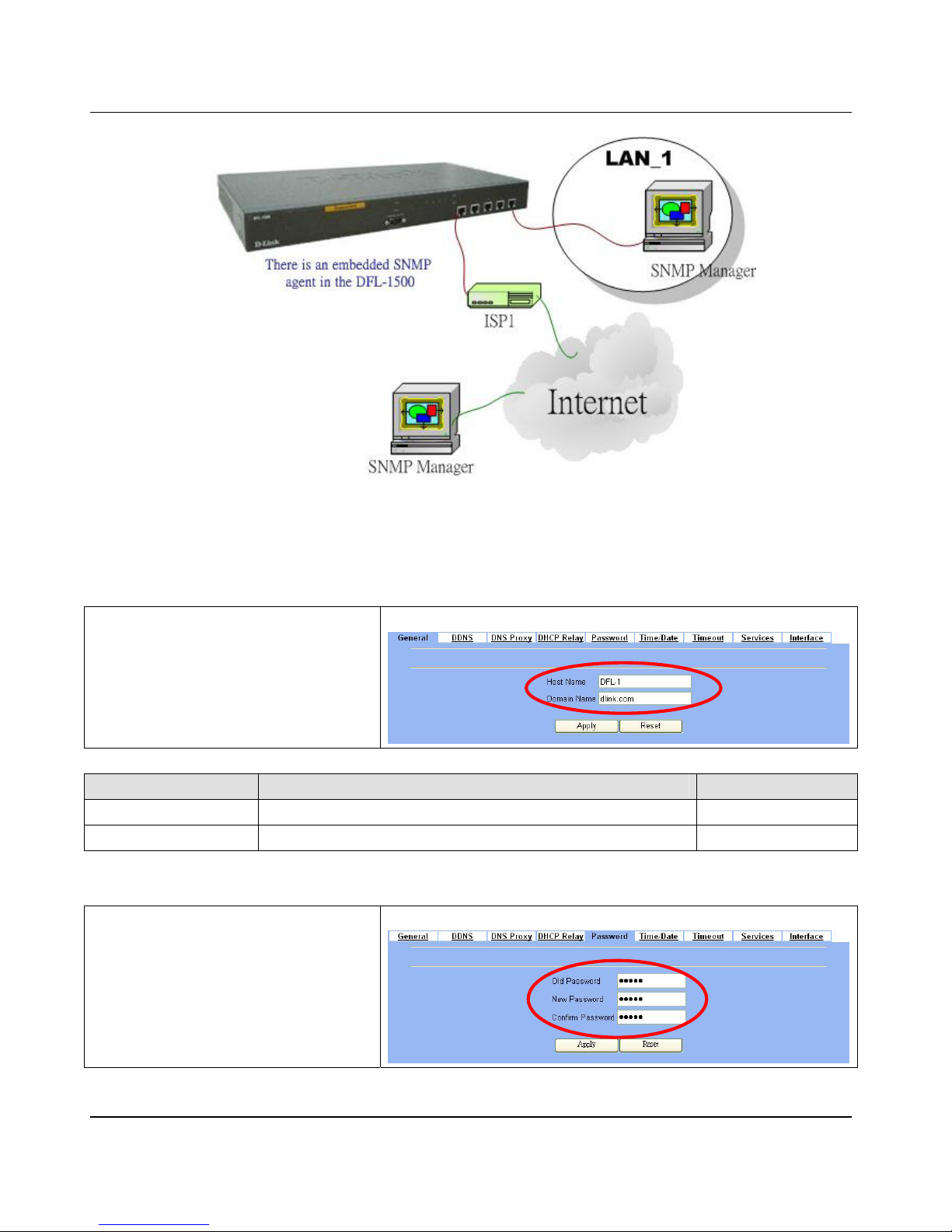
6. As the following Figure 4-5 demonstrated, there is an embedded snmp agent in the DFL-1500. So you can use SNMP
manager to monitor the DFL-1500 system status, network status ,etc. from either LAN or internet.
Page 30
D-Link Part I
24
Figure 4-5 It is ef ficient to use SNMP Mana ger to monitor DFL-1500 device
4.4 Steps
4.4.1 General settings
Step 1 - General Setup
Enter the Host Name as DFL-1, Domain Name
as the domain name of your company Click
Apply.
SYSTEM TOOLS > Admin Settings > General
FIELD DESCRIPTION EXAMPLE
Host Name The host name of the DFL-1500 device DFL-1
Domain Name Fill in the domain name of company dlink.com
Table 4-1 System Too ls - General Setup menu
Step 2 - Change Password
Enter the current password in the Old Password
field. Enter the new password in the New
Password and retype it in the Retype to
Confirm field. Click Apply.
SYSTEM TOOLS > Admin Settings > Password
Page 31
Syste m Tools DFL-1500 User Manual
25
FIELD DESCRIPTION EXAMPLE
Old Password The original passwor d of administrator admin
New Password The new selected password 12345
Confirm Password Double confirm the new selected password 12345
Table 4-2 Enter new password
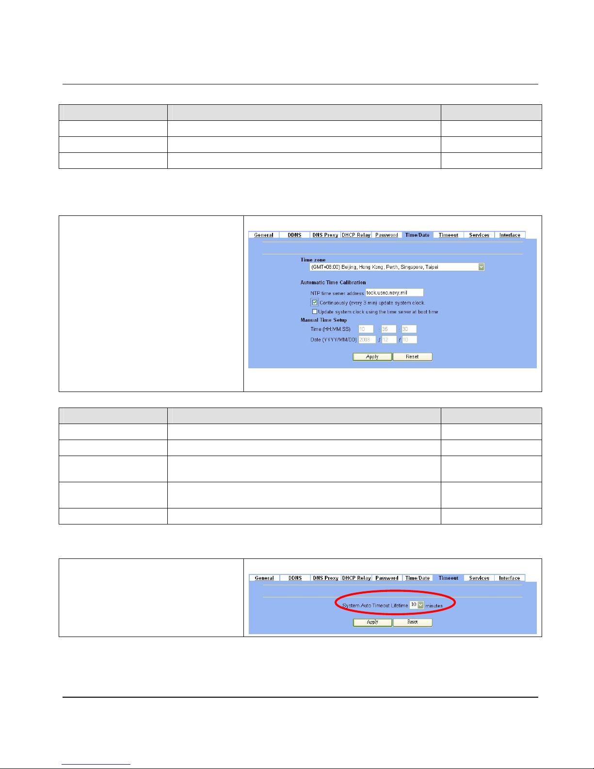
Step 3 - Setup Time/Date
Select the Time Zone where you are located.
Enter the nearest NTP time server in the NTP
time server address. Note that your DNS
must be set if the entered address requires
domain name lookup. You can also enter an IP
address instead. Check the Continuously
(every 3 min) update system clock and
click Apply. The DFL-1500 will immediately
update the system time and will periodically
update it. Check the Update system clock
using the time server at boot time and
click Apply if you want to update the clock at
each boot. If you want to manually change the
system time, uncheck the Continuously
(every 3 min) update system clock and
proceed by entering t he target date.
SYSTEM TOOLS > Admin Settings > Time/Date
FIELD DESCRIPTION EXAMPLE
Time zone the time zone of your area N/A
NTP time server address Use NTP time server to auto update date/time value tock.usno.navy.mil
Continuous l y (every 3 min)
update system clock
System will update system date/time value every 3 minutes to NTP time
sever.
Enabled
Update system clock using
the time server at boot time
System will update system date/time va lue to the NTP time server at boot
time.
disabled
Manual Time Setup Manual setting Ti me & Date value. N/A
Table 4-3 System Too ls – Time Data menu
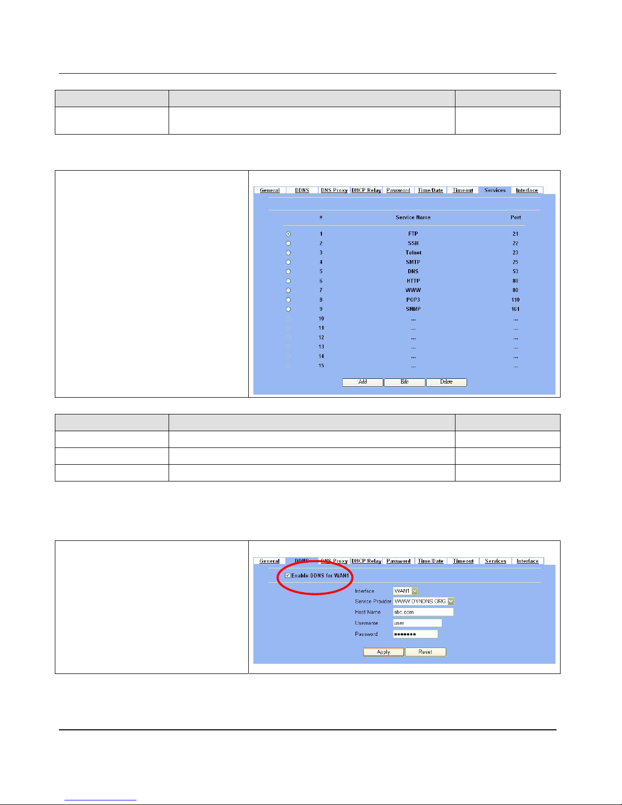
Step 4 - Setup Timeout
Select the target timeout (e.g. 10 min) from the
System Auto Timeout Lifetime. Click the
Apply button. Now the browser will not timeout
for the following 10 minutes after y our last
touching of it.
SYSTEM TOOLS > Admin Settings > Timeo ut
Page 32
D-Link Part I
26
FIELD DESCRIPTION EXAMPLE
System Auto Timeout
Lifetime
When system is idle for a specified time, system will force the people
who logins into the system will logout automatically.
10
Table 4-4 System Tools – Timeout menu
Step 5 - Configure Services
We can configure the service name and numeric
port number as the sam e group, so you can
simply use the domain name for the configuration
in the DFL-1500. If you want to add/edit/delete
the service record, just click the below button to
add/edit/delete it.
SYSTEM TOOLS > Admin Settings > Services
FIELD DESCRIPTION EXAMPLE
Add Add a service name record N/A
Edit edit an existing service name record N/A
Delete delete an existing service name record N/A
Table 4-5 Setup the service name recor d
4.4.2 DDNS setting
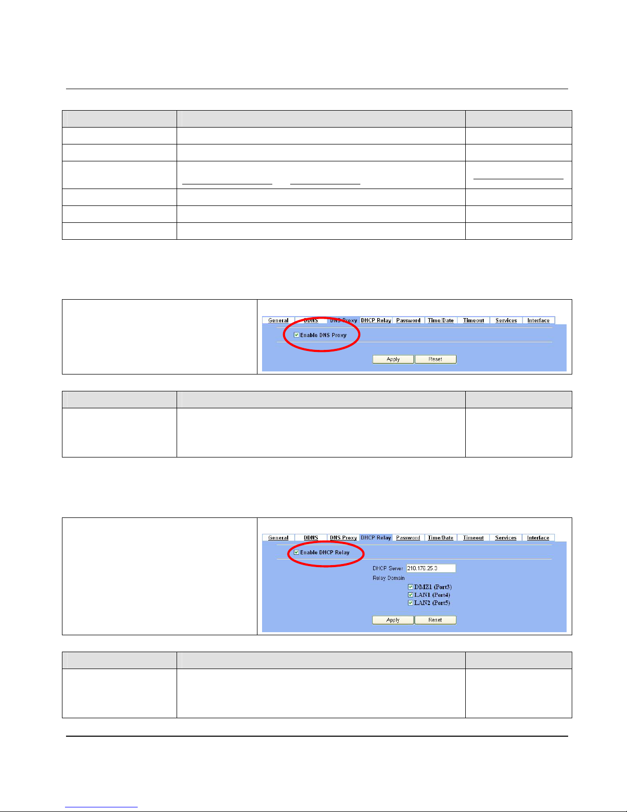
Step 1 - Setup DDNS
If the IP address of DFL-1500 WAN port is
dynamic allocated. You may want to have the
Dynamic DNS mechanism t o make your pa rtner
always use the same domain name (like xxx.com)
to connect to you. Select a WAN interface to
update the DDNS record. Here we supply two
DDNS Service Providers. Fill in the Host
Name, Username, Password supplied by the
DDNS web site. Please refer to the DDNS web
site for the detail information. Click Apply to
activate the settings.
SYSTEM TOOLS > Admin Settings > DDNS
Page 33
Syste m Tools DFL-1500 User Manual
27
FIELD DESCRIPTION EXAMPLE
Enable DDNS for WAN1 Enable DDNS feature of DFL-1500 Enabled
Interface Assign which public IP address of interface to the DDNS server. WAN1
Service Provide
The domain address of DDNS server. In the DFL-1500, we provide
WWW.DYNDNS.ORG
and WWW.DHS.ORG two websites for choice.
WWW.DYNDNS.ORG
Hostname The registered Hostname in the DDNS server. abc.com
Username The registered username in the DDNS server. user
Password The registered password in the DDNS server. 1234567
Table 4-6 System Tools – DDNS setting page
4.4.3 DNS Proxy setting
Step 1 - Setup DNS Proxy
Check the Enable DNS Proxy and click the
Apply to store the settings. From now on, your
LAN/DMZ PCs can use DFL-1500 as their DNS
server, as long as t he DN S server for DFL-1500
has been set in its WAN settings.
SYSTEM TOOLS > Admin Settings > DNS Proxy
FIELD DESCRIPTION EXAMPLE
Enable DNS Pr o xy
When the host of the LAN/DMZ sends a DNS Request, DFL-1500 will
request for forwarding it to the DNS server of the Default WAN link.
When there is a response from DNS, DFL-1500 will forward it back to
the host of the LAN/DMZ.
Enabled
Table 4-7 Sy stem Tools – DNS Proxy menu
4.4.4 DHCP Relay setting
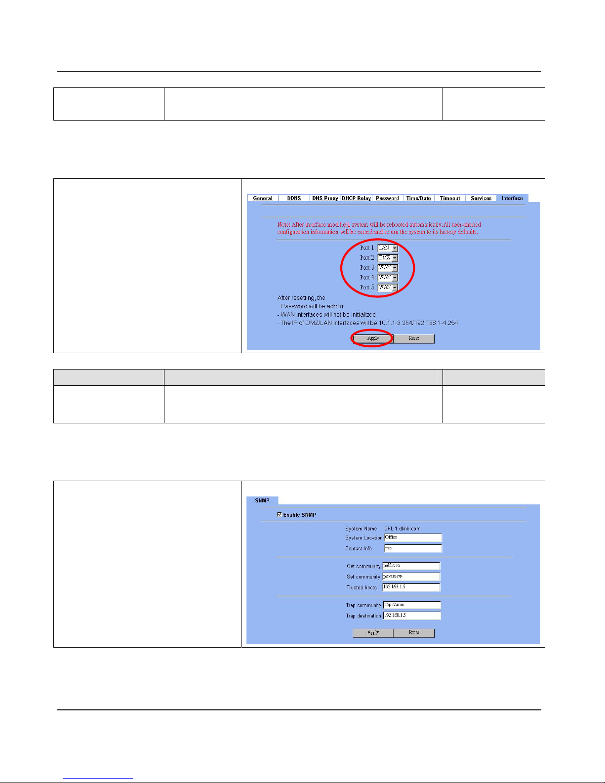
Step 1 - Setup DHCP Relay
Check the Enable DHCP Relay. Enter the IP
address of your DHCP server. Check the relay
domain of DFL-1500 that needs to be relayed.
Namely, che ck the one where t he DHCP server
resides and the one where DHCP clients are
located. Click the Apply button.
SYSTEM TOOLS > Admin Settings > DHCP Relay
FIELD DESCRIPTION EXAMPLE
Enable DHCP Relay
When the host of the L AN/DMZ in the DFL-1500 internal network sends
a DHCP request, DFL-1500 will forward it automatically to the specified
DHCP server (different subnet from the network segment of the DHCP
client).
Enabled
Page 34
D-Link Part I
28
DHCP Server Current locatio n of the DHCP server. 210.176.25.3
Relay Domain The locations of the DHCP clients.
Table 4-8 System Tools – DHCP Relay menu
4.4.5 Change DFL-1500 interface
Step 1 - Change Interface defi ni tion
The default port settings are 2 WAN ports, 1 DMZ
port and 2 LAN ports. But in order to fit our
requirement. Here we select 1 LAN (port1), 1
DMZ (port2) and 3 WAN (port3~5). And then
press apply button to reboot DFL-1500. Note that
the DMZ and LAN port IP addresses are going to
be 10.1.1.254 and 192.168.1.254 after device
finishes reboot. Besides, there should be at least
one WAN port and one LAN port existing in the
DFL-1500. You are not allowed to casually
change the interface to the state which has no
LAN port or WAN port.
SYSTEM TOOLS > Admin Settings > Interface
FIELD DESCRIPTION EXAMPLE
Port1 ~ P ort5
You can specify WAN / LAN / DMZ for each port by your preference.
However, there must be one WAN and one LAN interface existing in the
DFl-1500.
WAN / LAN / DMZ
Table 4-9 Change the DFL-1500 interfac e setting
4.4.6 SNMP Control
Step 1 - Setup S N M P C ontr ol
Through setting the related information in this
page, we can use SNMP manager to monitor the
system status, network sta t us of DFL-1500.
SYSTEM TOOLS > SNMP Control
Page 35

Syste m Tools DFL-1500 User Manual
29
FIELD DESCRIPTION EXAMPLE
Enable SNMP Enable the SNMP function or not. enabled
System Name The device name of DFL-1500. DFL-1.dlink.com
System Location The settled location of DFL-1500. Office
Contact Info The person who takes c harge of the DFL-1500. mis
Get community
The community which can get the SNMP information. Here
“community” is something like password.
public-ro
Set Community
The community which can get the SNMP information. Here
“community” is something like password.
private-rw
Trusted hosts The IP address which c an get or set community from the DFL-1500. 192.168.1.5
Trap community
The community which will send SNMP trap. Here “community” is
something like password.
trap-comm
Trap destination The IP address which will send SNMP trap from the DFL- 1500. 192.168.1.5
Page 36

Page 37
Remote Management DFL-1500 User Manual
31
Chapter 5
Remote Management
This chapter introduces remote management and explains how to implement it.
5.1 Demands
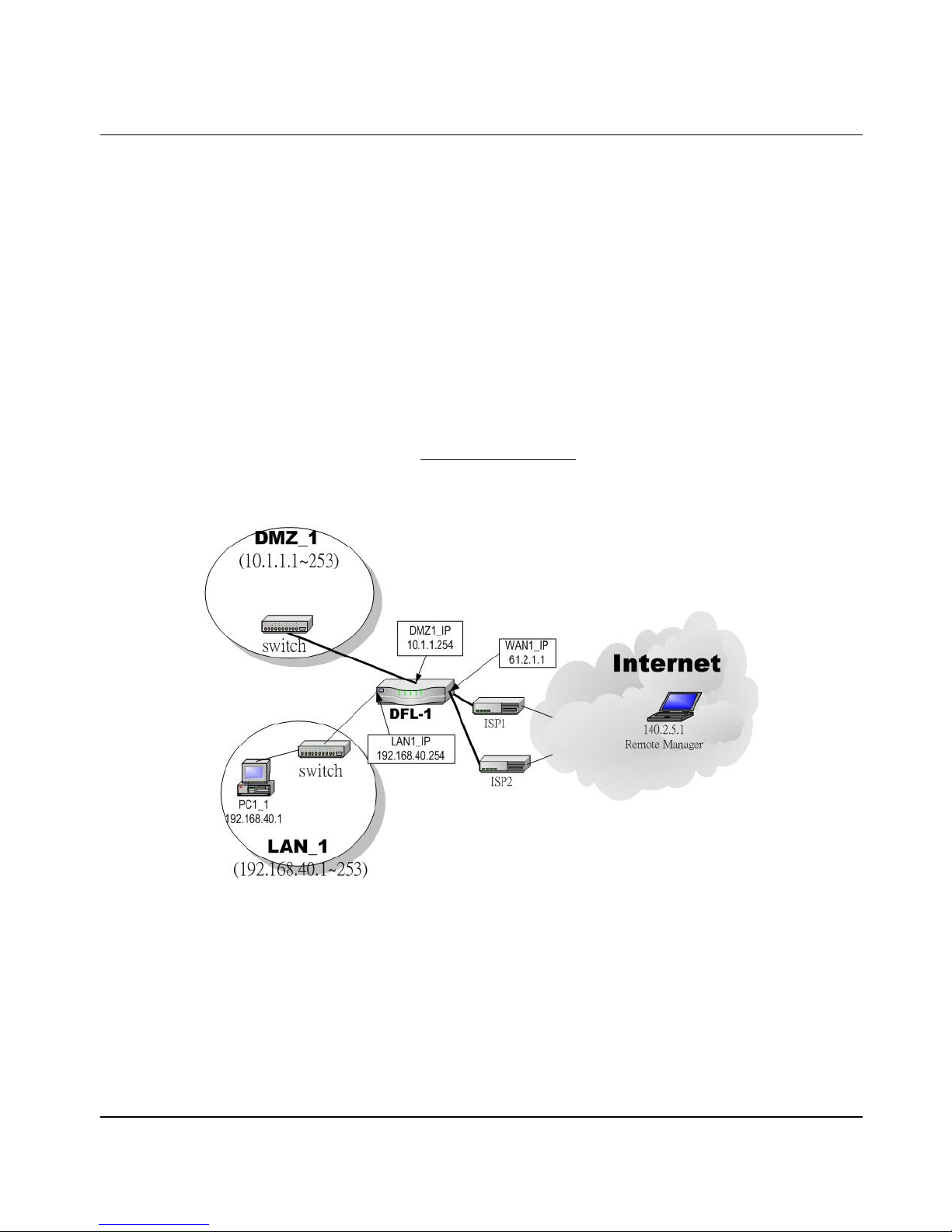
Administrators may want to manage the DFL-1500 remotely from any PC in LAN_1 with HTTP at port 8080, and from WAN_PC
with TELNET. In ad d iti on , the DFL-1500 may be more secure if monitored by a trusted host (PC1_1). What is more, the DFL-1500
should not respond to ping to hide itself. The remote management function in DFL-1500 devices is implemented by hidden Firewall
rules.
5.2 Methods
1. Only allow management by WAN_PC (140.2.5.1) at the WAN1 side.
2. Administrators can use browsers to connect to http://192.168.40.254:8080
for management.
3. Allow SNMP monitoring by PC1_1 (192.168.40.1) at the LAN1 side.
4. Do not respond to ICMP ECHO packets at the WAN1, WAN2 side.
Figure 5-1 Some mana gement method of DFL-1500
Page 38
D-Link Part I
32
5.3 Steps
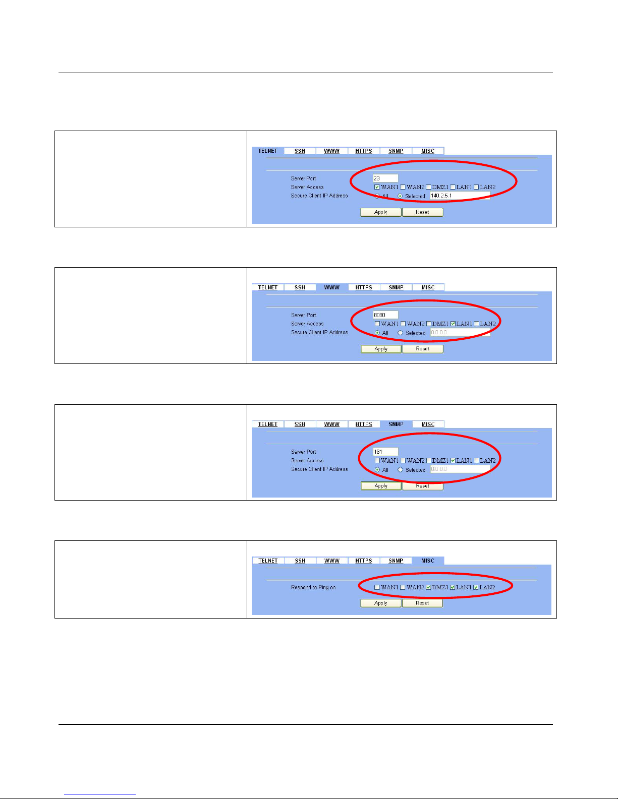
5.3.1 Telnet
Step 1 - Setup Telnet
Check the WAN1 checkbox. Click the Selected
of Secure Client IP Address, and then enter
the specified IP address (140.2.5.1) for
accessing DFL-1500. And click the Apply.
SYSTEM TOOLS > Remote Mgt. > TELNET
5.3.2 WWW
Step 1 - Setup WWW
Check the LAN1 checkbox, and enter the new
server port 8080 that will be accessed by the
user’s browser (http://192.168.40.254:8080). And
click the Apply. If you are configuring the
DFL-1500 with HTTP, your browser will then
automatically be directed to the new server port.
SYSTEM TOOLS > Remote Mgt. > WWW
5.3.3 SNMP
Step 1 - Setup SNMP
Check the LAN1 checkbox. In the Secure
Client Address field. If you prefer indicated
specified IP address. Just click the Selected,
and enter the valid IP address for reading the
SNMP MIBs at the DFL-1500. Here we click All
for all no IP range lim it ati on of cli ent s. Fina l ly cl i ck
the Apply.
SYSTEM TOOLS > Remote Mgt. > SNMP
5.3.4 ICMP
Step 1 - Setup ICMP
Uncheck the WAN1, WAN2 checkbox and make
others checked. Then click the Apply button.
SYSTEM TOOLS > Remote Mgt. > MISC
Page 39

Page 40

D-Link Part II
34
Part II
NAT、Routing & Firewall
Page 41
NAT DFL-1500 User Manual
35
Chapter 6
NAT
This chapter introduces NAT and explains how to implement it in DFL-1500.
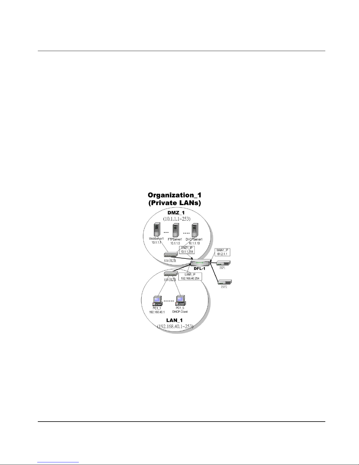
To facilitate the explanation on how DFL-1500 implements NAT and how to use it, we zoom in the left part of Figure 1-4
into Figure 6-1.
6.1 Demands
1. The number of public IP address allocated to each Internet subscribers is often very limited compared to the number of PCs
in the LAN1. Additionally, public-IP hosts are directly exposed to the Internet and have more chances to be cracked by
intruders.
2. Internet server s provided by your company may open many ports in default that may be dangerous if exposed to the public
Internet.
Figure 6-1 Topology for explanations of the NAT examples.
6.2 Objectives
1. Let PC1_1~PC1_5 connect to the Internet.
2. Let FTPServer1 be accessed by other Internet users.
Page 42
D-Link Part II
36
6.3 Methods
1. Assign private IP addresses to the PC1_1~PC1_5. Setup NAT at DFL-1500 to map those assigned private h osts under
LAN1 to the public IP address WAN_IP at the WAN1 side.
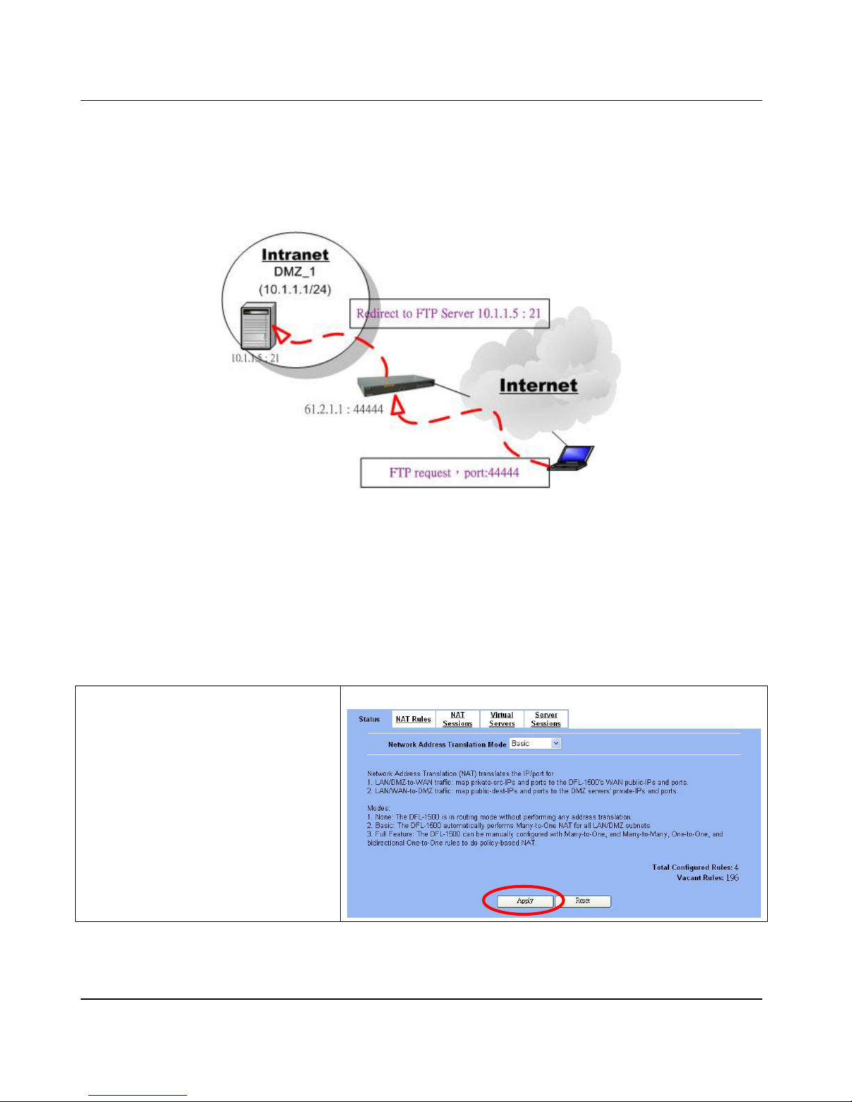
2. Assign a private IP address to the FTPServer1. Setup Virtual Server at DFL-1500 to redirect “any connections towards
some port of WAN1” to the port 21 at the FTPServer1.
Figure 6-2 DFL- 1500 plays the role as Virtual Server
As the above Figure 6-2 illustrates, the server 10.1.1.5 provides FTP service. But it is located on the DMZ region behind
DFL-1500. And DFL-1500 will act as a Virtual Server role which redirects the packets to the real server 10.1.1.5. And you
can announce to the internet users that there exists a ftp server ip/port is 61.2.1.1/44444. So, all the internet users will
just connect the 61.2.1.1/44444 to get ftp service.
6.4 Steps
6.4.1 Setup Many-to-one NAT rules
Step 1 - Enab le NAT
Select the Basic from the list of Network
Address Translation Mode. Click Apply.
Now the DFL-1500 will automatically set the NAT
rules for LAN/DMZ zones. Namely, all internal
networks can establ i sh con nec t ions to t he ou tsi de
world if the WAN settings are correct.
ADVAN C E D SETTIN G S > N AT > S t atus
Page 43
NAT DFL-1500 User Manual
37
FIELD DESCRIPTION EXAMPLE
Network Address Translation
Mode
None:The DFL-1500 is in routing mode without performing any address
translation.
Basic:The DFL-1500 automatically performs Many-to-One NAT for all
LAN/DMZ subnets.
Full Feature:The DFL-1500 can be manually configured with
Many-to-One, and Many-to-Many, One-to-One, and bidirectional
One-to-One rules to do policy-based NAT.
Basic
Table 6-1 Determine Network Address Translation Mode
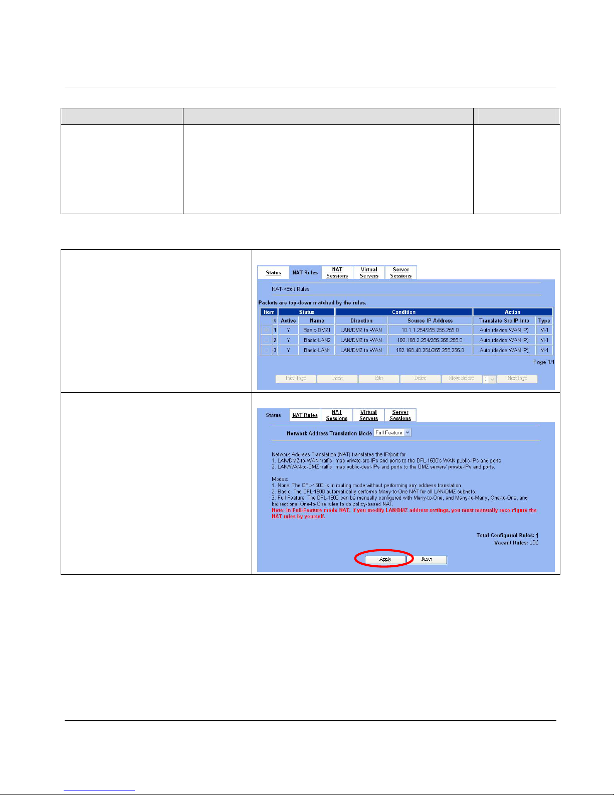
Step 2 - Check NAT Rules
As described in the above, the DFL-1500 has set
the three rules for the LAN1, LAN2, and DMZ1
zones. They all belong to the Many-to-One
(M-1) type that will map man y private addr esses
to the automatically chosen public IP address.
When the WAN interfaces change the IP, these
rules do not require any manual modifications for
the changed public IP addresses. The rules will
automatically reload the new settings. In the
Basic mode, you cannot edit the rules in this
page.
ADVANCED SETTI NGS > NAT > NAT Rules
Step 3 - Switch the NAT Mode
Select the Full Feature from the list of
Network Address Translation Mode. Click
Apply. After applying the setting, the page will
highlight a warning saying that the rules are no
more automatically maintained by the DFL-1500.
If you change the LAN/DMZ IP settings, you have
to manually update related rules by yourself.
Otherwise, hosts in your LAN/DMZ cannot
establish connections to the hosts in the WAN
side.
ADVANCED SETTI NGS > NAT > Status
Page 44
D-Link Part II
38
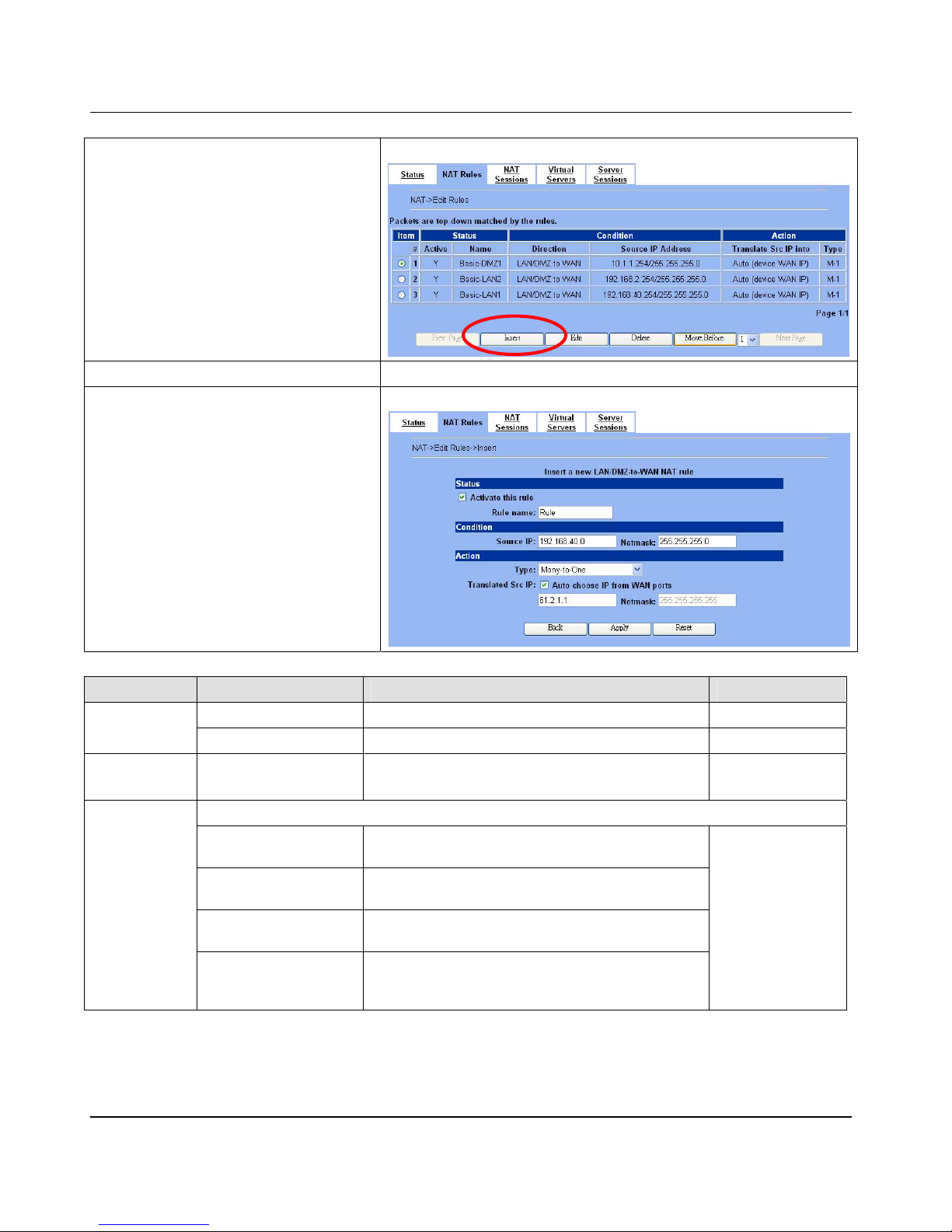
Step 4 - Customize NAT Rules
In the full-feature mode, the rules can be further
customized. Incoming packets from LAN/DMZ
zones are top-down matched by the NAT rules.
Namely, NAT implements first match. Select the
rule item that you want to do with: insert a new
rule before it; delete it; move it before the
list-box chosen item.
ADVANCED SETTINGS > NAT > NAT Rules
Step 5 - Insert NAT Rule
Step 5. a — Insert an Many-to-One
Rule
As described in the ab ove, Many-to-One NAT is
the default NAT rule type in the Basic mode. If
you have other alias LAN/DMZ subnets, you can
manually add a Many-to-One NAT rule for them.
First select the Type as Many-to-O ne , che ck the
Activate this rule, enter a Rule name for
this rule, enter the private-IP subnet (an IP
address with a netmask) to be translated, and
enter the public IP address for being translated
into, You can check the Auto choose IP from
WAN ports. The DFL-1500 will automatically
determine which WAN IP is to be translated int o.
ADVANCED SETTINGS > NAT > NAT Rules > Insert
FIELD DESCRIPTION EXAMPLE
Activate this rule The NAT rule is enabled or no t enabled
Status
Rule name The NAT rule name Rule
Condition Source IP / Netmask
Compared with the incoming packets, whether Source
IP/Netmask is match ed or no t.
192.168.40.0 /
255.255.255.0
Type
Many-to-One
Map a pool of private IP addresses to a single public IP
address chosen from the WAN ports.
Many-to-Many
Map a pool of private I P addresses to a pool of public IP
addresses chosen from the WAN ports.
One-to-One
Map a single private IP address to a single public IP
address chosen from the WAN ports.
Action
One-to-One
(bidirectional)
An internal host i s fully mapped to a WAN IP address.
Notice that you must add a firewall rule to forward WAN
to LAN/DMZ traffic.
Many-to-One
Page 45
NAT DFL-1500 User Manual
39
Translated Src IP
Auto choose IP from WAN ports:Only work in
Many-to-One type, the default WAN link is the default
source interface for NAT translation. Only when all ports
are used, it will use the next NAT interface.
Another way is to specify IP address / Netmask by self.
Auto choose IP from
WAN ports
Table 6-2 Add a NAT rule
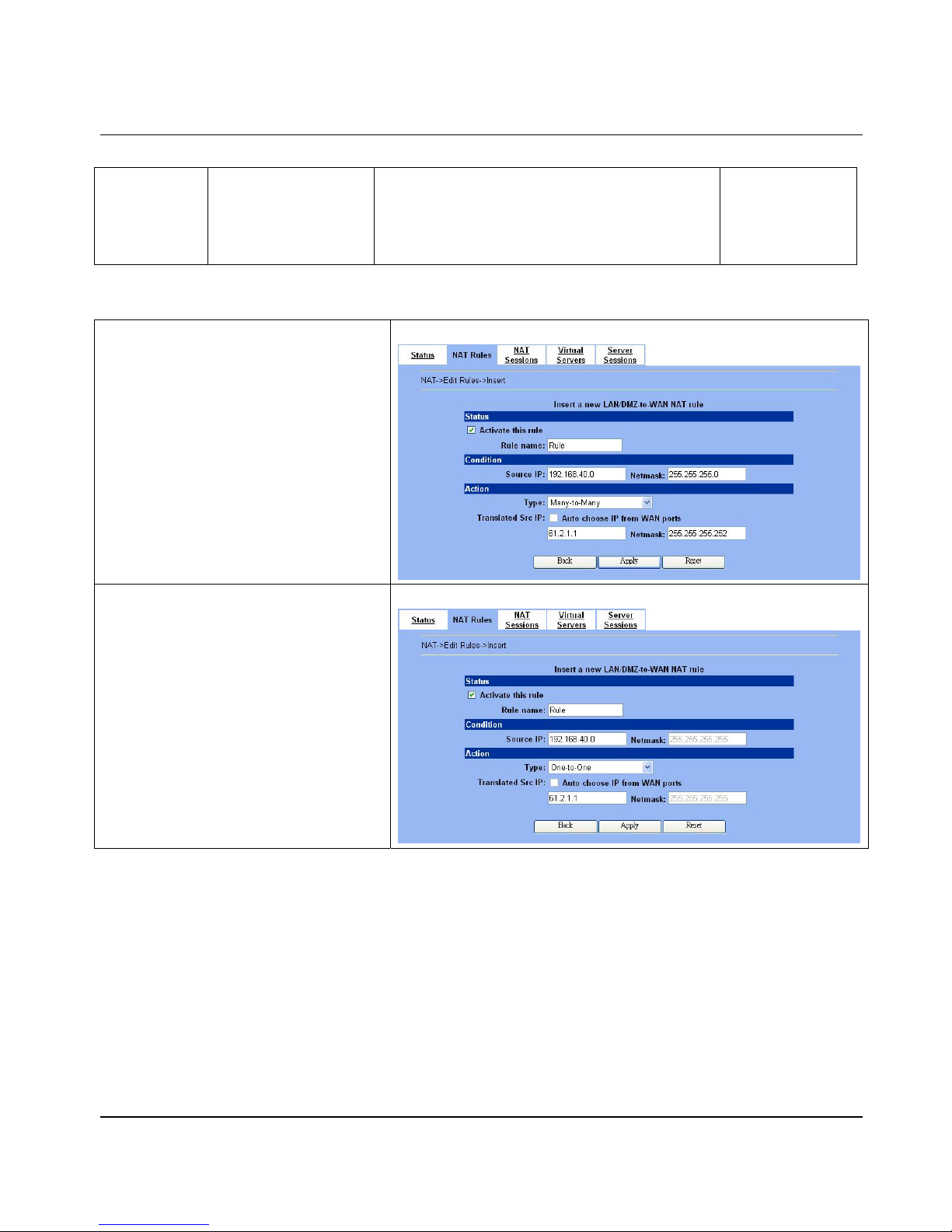
Step 5.b — Insert an Many-to-Many
Rule
If your ISP has assigned a range of public IP to
your company, you can tell DFL-1500 to translate
the private IP addresses into the pool of public IP
addresses. The DFL-1500 will use the first public
IP until DFL-1500 uses up all source ports for the
public IP. DFL-1500 will then choose the second
public IP from the address pool. Select
Many-to-Many from the Type. Enter the subnet
with an IP address and a netmask. Other fields
are the same with those of Many-to-One rules.
However, the DFL-1500 w ill no longer choose the
device IP for you. It w ill choose the IP from the
address pool you have entered.
ADVANCED SETTING S > NAT > NAT Rules > Insert
Step 5.c — Insert an One-to-One Rule
Though you may have many publi c IP addre s s for
translation, you may want to make some private
IP to always use a public IP . In th is c a se , you c a n
select One-to-One from the Type, and enter the
private-public IP address pair in the Source IP
and the Translated Source IP fields.
ADVANCED SETTING S > NAT > NAT Rules > Insert
Page 46
D-Link Part II
40
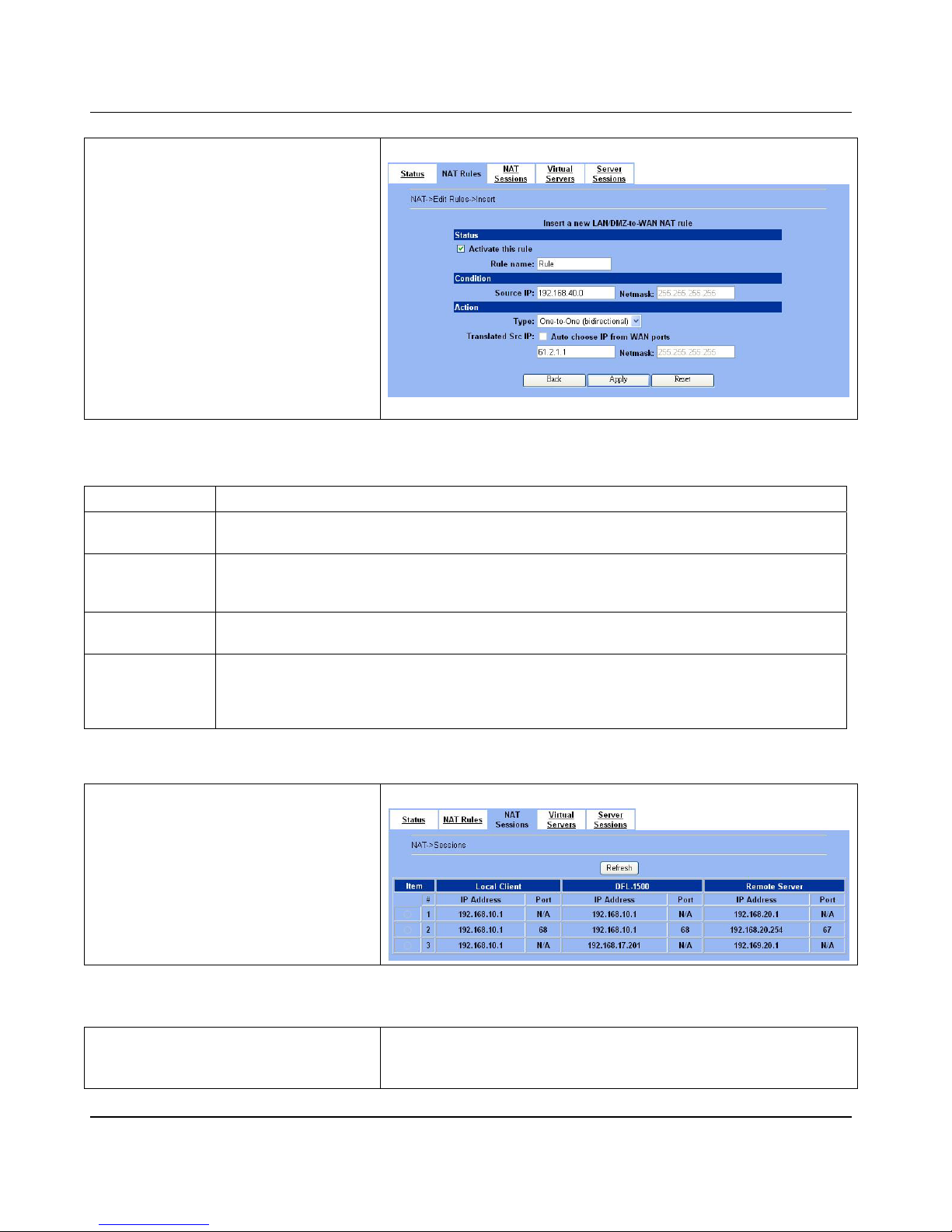
Step 5.d — Insert a One-to-One
(Bidirectional) Rule
The above three mo des allow LAN/D MZ-to-WAN
sessions establishment but do not allow
WAN-to-LAN/DMZ sessions. WAN-to-LAN/DMZ
sessions are allowed by Virtual Server rules. You
can make the One-to-One NAT in the above to
incorporate the WAN-to-LAN/DMZ feature by
selecting the One-to-One (Bidirectional)
from the Type. Note th at WAN -t o-LAN /D MZ t ra f fic
will be blocked by the Firewall in default. You
have to add a Firewall rule to allow such traffic. If
you expect a LAN/DMZ host to be fully accessed
by public Internet users, use this mode. Note that
this mode is extremely dangerous because the
host is fully exposed to the Internet and may be
cracked. Alway s use Virtual Server rul es first.
ADVANCED SETTINGS > NAT > NAT Rules > Insert
How to determine which NAT type is best choice for you. Here we have some suggestions as the following table description.
Type Usage moment
Many-to-One
If the public IP addresses of your company is insufficient, and you prefer to increase the node which can
connect to the inter net. You can just choose the Many-to-One type to fit your req uest.
Many-to-Many
If the public IP ad dress of your company is not only one node (e x. you have applied extra-one ISP). You
may use the Many-to-Many type to make the multiple public addre sses sharing the inbound bandwidth. So
your inbound and ou tbound traffic will be more flexible.
One-to-One
If you just wish one local IP address to connect to the inter ne t, and prohib i t othe rs to conne ct to the interne t.
You can specify the One-to-One type.
One-to-One
(bidirectional)
If you wish to expose the local pc onto the internet, and open all internet services outside. You can specify
the One-to-One (bidirectional) type. This will make the local pc you specified fully exposed to the internet.
Additionally you must add a firewall rule to allow WAN to LAN traffic forward. Then you can finish the
settings. Be care ful to use this type, or it will endanger your network security.
Table 6-3 The NAT type comparison
Step 6 - View the LAN to WAN Sessions
Click the NAT Sessions to see the sessions
between LAN to WAN.
ADVAN C E D SETTIN G S > N AT > NAT Ses sions
6.4.2 Setup Virtual Server for the FtpServer1
Step 1 - Device IP Address
Setup the IP Address and IP Subnet Mask for
the DFL-1500 of the DMZ1 interface.
BASIC SETUP > DMZ Settings > DMZ1 Status
Page 47
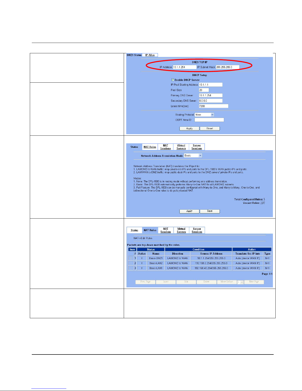
NAT DFL-1500 User Manual
41
Step 2 - Client IP Range
Enable the DHCP server if you want to use
DFL-1500 to assign IP ad dresses to the
computers under DMZ 1. Here we make the
DHCP feature enabled.
Step 3 - Apply the Changes
Click Apply to save your settings.
Step 4 - Check NAT Status
The default setting of NAT is in Basic Mode.
After applying the Step 3, the NAT is
automatically configured with three r ules to let all
private-IP LAN/DMZ-to-WAN requests to be
translated with the public IP assigned by the ISP.
ADVANCED SETTI NGS > NAT > Status
Step 5 - Check NAT Rules
The DFL-1500 has added three NAT rules. The
rule Basic-DMZ1 (number 1) means that, when
matching the condition (requests of
LAN/DMZ-to-WAN direction with its source IP
falling in the range of
10.1.1.254/255.255.255.0), t he request will
be translated into a public-source-IP requests,
and then be forwarde d to the destinations.
ADVANCED SETTI NGS > NAT > NAT Rules
Step 6 - Setup IP for the FTP Server
Assign an IP of 10.1.1.1/255.255.255.0 to the
FTP server under DMZ1. Assu me t he FTP Serv er
is at 10.1.1.5. And i t is l i steni ng on t he w el l -known
port (21).
Page 48
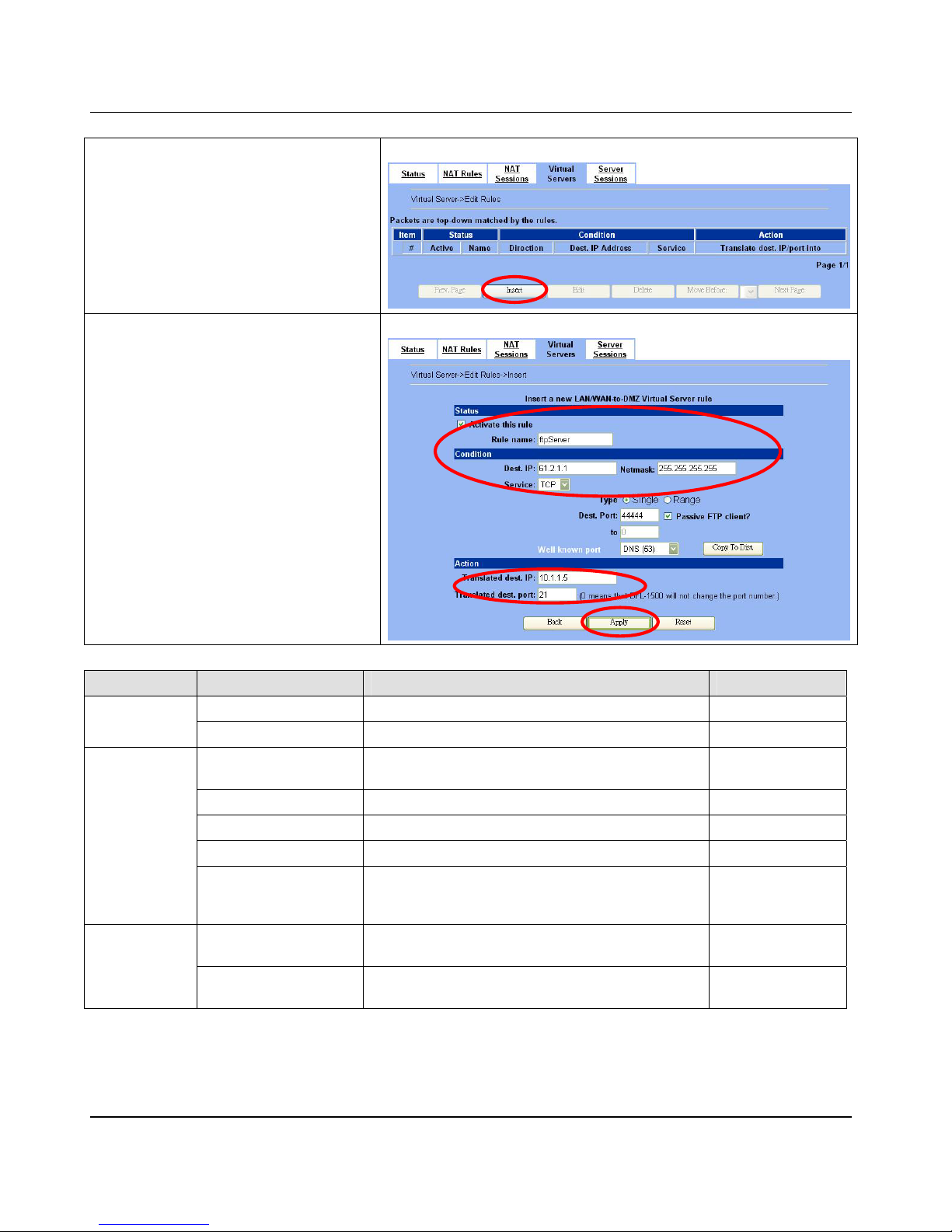
D-Link Part II
42
Step 7 - Setup Server Rules
Insert a virtual server rule by clicking the Insert
button.
ADVANCED SETTINGS > NAT > Virtual Servers
Step 8 - Customize the Rule
Customize the rule name as the ftpServer. For
any packets with its destination IP equaling to the
WAN1 IP (61.2.1.1) and destination port
equaling to 44444, ask DFL-1500 to translate the
packet’s destination IP/port into 10.1.1.5/21.
Check the Passive FTP client? to maximize
the compatibility of the FTP protocol. This is
useful if you want to provide connectivity to
passive FTP clients. For passive FTP clients, the
server will return them the private IP address and
the port number for them to connect back to do
data transmissions. Since the private IP from
them cannot be routed to our zone, the data
connections would fail . A fter e n abl i ng thi s fea ture,
the DFL-1500 will translate the private IP/port into
an IP/port of its own. Thus the problem is
gracefully solved. Click Apply to proceed.
ADVANCED SETTINGS > NAT > Virtual Servers > Insert
FIELD DESCRIPTION EXAMPLE
Activate this rule The Virtual Server rule is enabled or not enabled
Status
Rule name The Virtual Server rule name ftpServer
Dest IP / Netmask
The public IP address and IP netmask of the Virtual
Server.
61.2.1.1 /
255.255.255.255
Service Any, TCP or UDP TCP
Type Port is Single or Range Single
Dest Port The port number in the inter net. 44444
Condition
Passive FTP client
If the Passive FTP client is checked, it will connect to the
internal DMZ FTP server of DFL-1500 when FTP client
uses passive mode. Otherwise, it will not work.
enabled
Translated dest IP
The IP address which is actually transferred to the
internal DMZ
10.1.1.5
Action
Translated dest port
The port number which is actually transferred to the
internal DMZ.
21
Table 6-4 Add a Virtual Server rule
Page 49
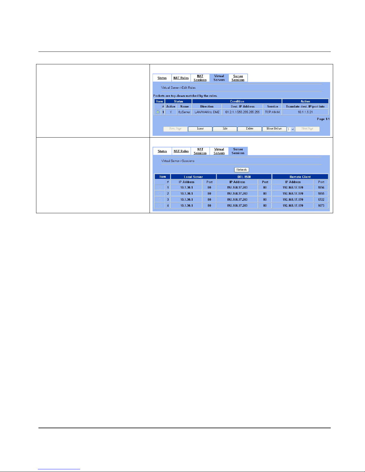
NAT DFL-1500 User Manual
43
Step 9 - View the Result
Now any request towards the DFL-1500’s WAN1
IP (61.2.1.1) with port 44444 will be translated
into a request towards 10.1.1.5 with port 21,
and then be forwarded to the 10.1.1.5. The
FTP server listening at port 21 in 10.1.1.5 will
pick up the request.
ADVANCED SETTI NGS > NAT > Virtual Server s
Step 10 - View the WAN to LAN
Sessions
Click the Server Sessions to see the sessions
between WAN to LAN.
ADVANCED SETTI NGS > NAT > Server Sessi ons
Page 50

Page 51
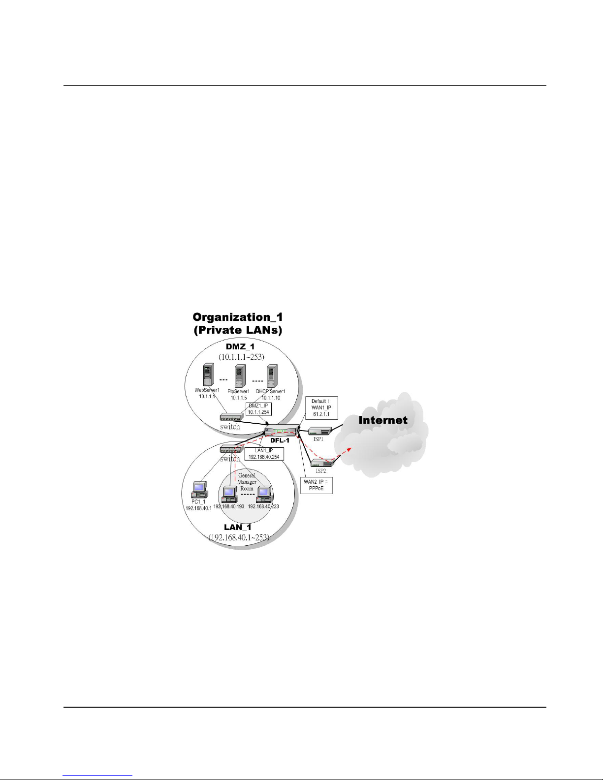
Routing DFL-1500 User Manual
45
Chapter 7
Routing
This chapter introduces how to add static routing and policy routing entries
To facilitate the explanation on how DFL-1500 implements routing and how to use it, we zoom in the left part of Figure 2-1
into Figure 7-1
7.1 Demands
1. The bandwidth subs cribed from ISP1 is insufficient so that some important traffic, say traffic towards the subnet
140.116.53.0/255.255.255.0, is blocked by the other traffic.
2. The bandwidth subscribed from ISP1 is insufficient so that some important traffic, say the traffic from PCs belonging to the
General-Manager-Room department (192.168.40.192 / 255.255.255.192) , is blocked by the other traffic.
Figure 7-1 Add po licy routing entry for the General-Manag er-Room department
7.2 Objectives
1. The network administrator plans to solve the problem by subscribing the second link (ISP2). He/She wires the ISP2 to the
WAN2 socket of the DFL-1. Now t here are two WAN links connected to the DFL-1. He/she hopes that all the packets
destined to the subnet 140.116.53.0/255.255.255.0 will pass through the WAN2 link instead of the default WAN1 link. In
such a way, the WAN2 link can offload the traffic.
2. The same as th e above. However, r outin g table can only be sp ecified by destin ations. That is, r outing t able can onl y direct
some packets “destined to” somewhere through some link. It cannot direct some packets “from” somewhere through some
Page 52
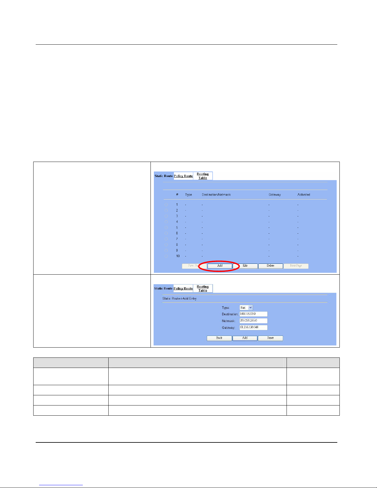
D-Link Part II
46
link. The policy route can solve this problem. He/she hopes that all the packets from the General-Manager-Room will pass
through the WAN2 link instea d of the defaul t WAN1 l ink.
7.3 Methods
1. Add a static routi n g ent ry to direct the packets to wa rds 140.116.53.0/255 .255.255.0 thro ugh th e WA N2 lin k.
2. Add a policy routing entry for the pack ets coming from General-Manager-Room department (192.168.40.192 /
255.255.255.192 ) thr oug h the WAN2 link.
7.4 Steps
7.4.1 Add a static routing entry
Step 1 - Add a static routing entry
Click the Add button to the next process.
Advanced Settings > Routing > Static Route
Step 2 - Fill out the related field
Fill in the destination and the netmask field with
140.116.53.0 and 255.255.255.0. Assign the next
hop Gateway as 61.216.120.148 (the WAN2
IP address). Click Add to proceed.
Advanced Settings > Routing > Static Route > Add
FIELD DESCRIPTION EXAMPLE
Type
Determine this static routing entry rec ord is multiple hosts (Net) or a single
host (Host)。
Net
Destination The desti nation IP address of this static routing entry record. 140.116.53.0
Netmask The destination IP Netmask of this static routing entry record. 255.255.255.0
Gateway The defa ult gateway of this static routing entry record. 61.216.120.148
Table 7-1Add a static routing entry
Page 53
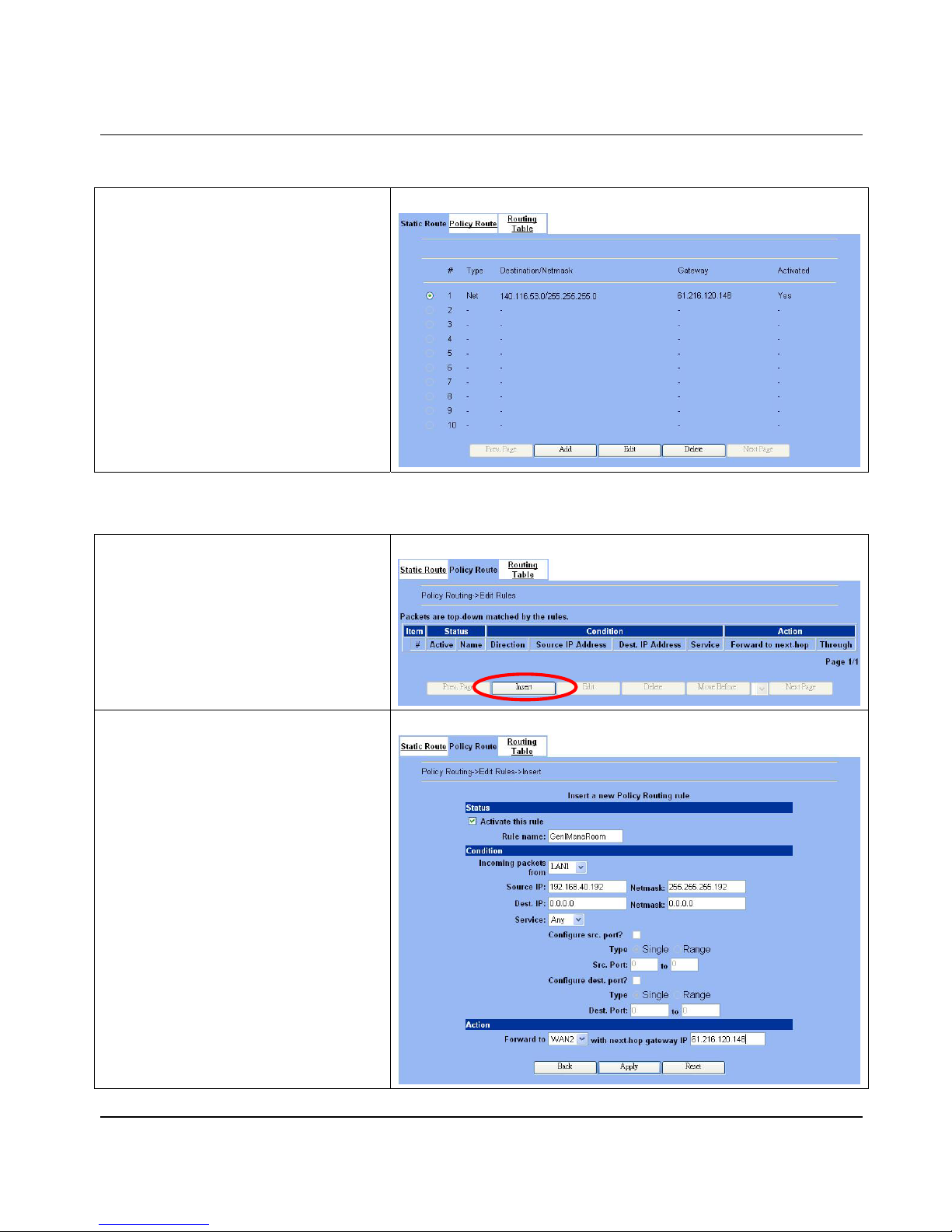
Routing DFL-1500 User Manual
47
Step 3 - View the result
The static route has been stored. After filling data
completely, view the static routing entries which
have been set.
Advanced Settin gs > Routi ng > Stati c Route
7.4.2 Add a policy routing entry
Step 1 - Insert a policy routing entry
Click Insert button to add a policy routing entry.
Advanced Settings > Routing > Policy Route
Step 2 - Fill out the related field
For the General-Manager-Room department, we
need to set an extra policy routing entry for them.
So in the Status region, make sure the
Activate the rule is enabled. Rule name field
fill in GenlManaRoom. In the Condition region,
we fill 192.168.40.192 in Source IP field. Fill
255.255.255.192 in the Netmask field. In the
Action region, fill forward to WAN2 with next-hop
gateway 61.216.120.148. After setting as
above, the packets which match the condition,
they will follow the predefined action to forward to
the next hop.
Advanced Settings > Routing > Policy Route > Insert
Page 54
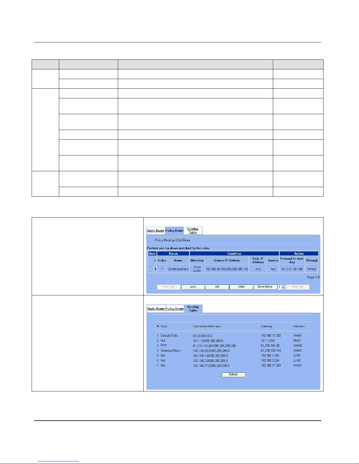
D-Link Part II
48
FIELD DESCRIPTION EXAMPLE
Activate this rule The policy routing r ule is enabled or not. enabled
Status
Rule name The policy routing rule name. GenlManaRoom
Incoming packets from Packets comes from which interface LAN1
Source IP & Netmask
Verify if the incoming packets belong to the range of the Source
IP/Netmask in the policy routing rule.
192.168.40.192 /
255.255.255.192
Dest IP & Netmask
Verify if the incoming packets belong to the range of the Dest
IP/Netmask in the policy routing rule.
0.0.0.0 / 0.0.0.0
Service Verify what is the service of this packet? Any
Configure src. port?
Type Src. port
Check the source port of the incoming packets. If checked, what is
the range of the port?
No
Condition
Configure dest. port?
Type Dest. port
Check the dest port of the incoming packets. If checked, what is the
range of the port?
No
Forward to
If the packet is matched to this rule, which interface does this packet
sent out to?
WAN2
Action
Nexthop gateway IP The next gateway IP address of forwarding interface. 61.216.120.148
Table 7-2 Add a policy routing entry
Step 3 - View the r esu l t
After filling data completely, view the policy
routing entri es wh ich have been set.
Advanced Settings > R outing > Policy Route
Step 4 - Show t he routi ng tabl e
Finally click the “Routing Table” to see all the
current routing table information.
Advanced Settings > Routing > Routing Table
Page 55
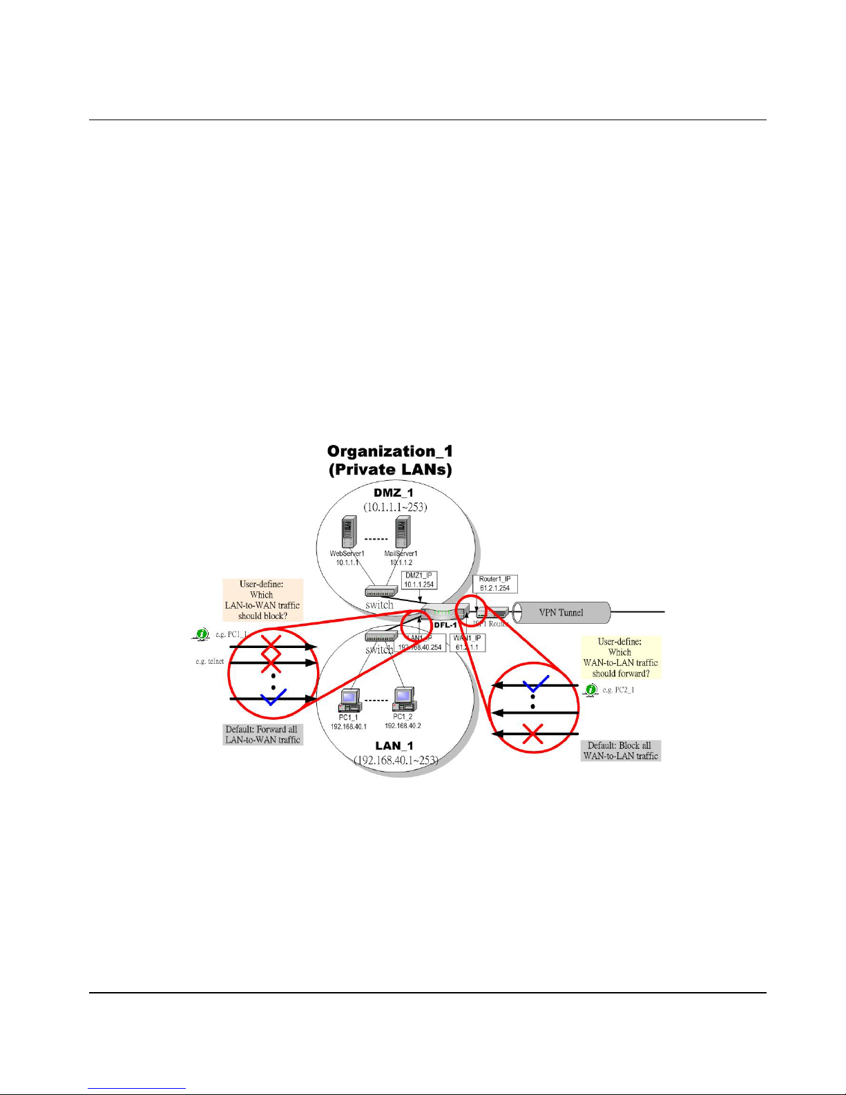
Firewall DFL-1500 User Manual
49
Chapter 8
Firewall
This chapter introduces firewall and explains how to implement it.
8.1 Demands
1. Administrators d etect that PC1_1 in LA N_1 is doing something that may hurt our company and should instantly block his
traffic towards the I nternet.
2. A DMZ server was attacked by SYN-Flooding attack and requires the DFL-1500 to protect it.
8.2 Objectives
1. Block the traffic from PC1_1 in LAN1 to the Internet in WAN1.
2. Start the SYN-Flooding protection.
Figure 8-1 Setting up the firewall rule
8.3 Methods
1. Add a LAN1-to-WAN1 Firewall rule to block PC1_1.
2. Start the SYN-Flooding protection by detecting statistical half-open TCP connections.
Page 56
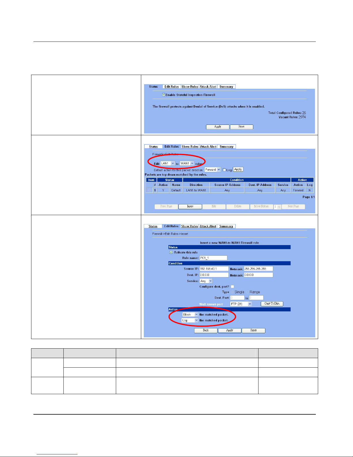
D-Link Part II
50
8.4 Steps
8.4.1 Block internal PC session (LAN Æ WAN )
Step 1 - Setup NAT
Check the Enable Stateful Inspection
Firewall checkbox , and click the Apply.
ADVANCED SETTINGS > Firewall > Status
Step 2 - Add a Firewall Rule
Select LAN1 to WAN1 traffic direction. The
default action of this direction is to forward all
traffic without logging anyt hing. Click Insert to add
a Firewall bl ock r ule befor e t he d efau lt r ule to stop
the bad traffic.
ADVANCED SETTINGS > Firewall > Edit Rules
Step 3 - Customize the rule
Check the Activate this rule checkbox.
Enter the rule name as PC1_1, and enter the IP
address of PC1_1 (192.168.40.1 /
255.255.255.255). Select Block and Log to
block and log the mat ched tr a ff i c. Cl i ck the Apply
to apply the changes.
ADVANCED SETTINGS > Firewall > Edit Rules > Insert
FIELD DESCRIPTION EXAMPLE
Activate this rule Enable the firewall rule for later using enabled
Status
Rule name The name of the Firewall rule PC1_1
Condition
Source IP & Netmask
Compared with the incoming packets, whether Source
IP/Netmask is match ed or no t.
192.168.40.1
255.255.255.255
Page 57
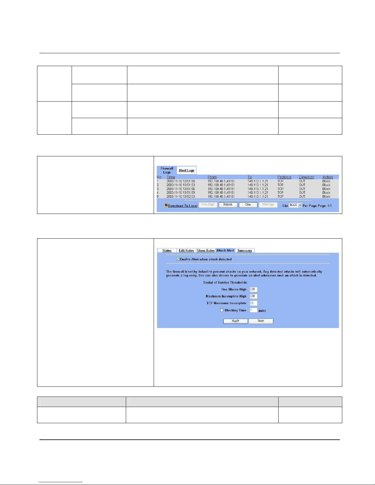
Firewall DFL-1500 User Manual
51
Dest IP & Netmask
Compared with the incoming packets, whether Dest IP/Netmask
is matched or not.
0.0.0.0
0.0.0.0.
Service
Verified the service of packet is belong to each TCP、UDP、
ICMP.
Any
Forward / Block the
matched packet
If packet is matched the rule condition, Forward or Block this
matched packet?
Block
Action
Don’t log / Log the
matched packet
If packet is matched the rule condition, Log or Don’t log this
matched packet?
Log
Table 8-1 Insert a Firewall rule
Step 4 - View the Firewall Log
You can go to DEVICE Status>Firewall Logs
>Firewall Logs to view the firewall logs. If you
prefer to download these logs, please click the
“Download To Local” button to save the logs to
localhost.
DEVICE Status > Fi rewall Logs > Fir ewall Logs
8.4.2 Setup Alert detected attack
Step 1 - Setup Attack Alert
With the Firewall enabled, the DFL-1500 is
already equipped with an Anti-DoS engine within
it. Normal DoS attacks will show up in the log
when detecting and blocking such traffic.
However, Flooding attacks require extra
parameters to recognize. Check the Enable
Alert when attack detected checkbox.
Enter 100 in the One Minute High means that
DFL-1500 starts to generate alerts and delete the
half-open states if 100 half-open states are
established in the last minute. Enter 100 in the
Maximum Incomplete High means that
DFL-1500 starts to generate alerts and delete
half-open states if the current number of
half-open states reaches 100. Enter 10 in the
TCP Maximum Incomplete means that
DFL-1500 starts to generate alerts and delete
half-open states if the number of half-open states
towards a server (SYN-Flooding attack) reaches
10. Check the Blocking t ime if you want to
stop the traffic towards the server. During this
blocking time, the server can di gest the loa ding.
ADVANCED SETTINGS > Firewall > Attack Alert
FIELD DESCRIPTION EXAMPLE
Enable Alert when attack detected
Enable the firewall alert to detect Denial of Service (DoS)
attack.
Enabled
Page 58

D-Link Part II
52
Denial of Service Thresholds
One Minute High
This is the rate of new half –open sessions that causes the
firewall to start deleting half open sessions. When the rate of
new connection attempts rises above thi s numbe r, the DFL-1500
deletes half-open sessions as required to accommodate new
connection attempts.
100
Maximu m Incomp lete High
This is the number of existing half-open sessions that causes the
firewall to start deleting half-open sessions. When the number of
existing half- open sessions rise s above this number, the
DFL-1500 deletes half-open sessions as required to
accommodate new connection requests.
100
TCP Maximum Incomplete
This is the number of existing half-open TCP sessions with the
same destination host IP address that causes the firewall to start
dropping half-open ses sion s to tha t same dest inat io n host IP
address. Enter a number between 1 and 250. As a general rule,
you should choose a smaller number for a smaller network, a
slower system or limited bandw idth.
10
Blocking Time
When TCP Maximum Incomplete is reached you can choose if
the next session should be allowed or blocked. If you chec k
Blocking Time any new sessions will be blocked for the length
of time you specified in the next field (min) and all old
incomplete sessi ons will be cleared during this period. If you
want strong security, it is better to block the traffic for a short
time, as will give the serv er some time to digest the loading.
disabled
(min) Enter the length of Blocking Time in minutes. 0
Table 8-2 Setup the Denial of Service Thresholds of attack alert
Page 59

Page 60

D-Link Part III
54
Part III
Virtual Private Network
Page 61

VPN Technical Introd uction DFL-1500 User M a nual
55
Chapter 9
VPN Technical Introduction
This chapter introduces VPN related technology
9.1 Terminology Explanation
9.1.1 VPN
A VPN (Virtual Private Network) logically provides secure communications between sites without the expense of leased site-to-site
lines. A secure VPN is a combination of encryption, tunneling, authentication, and access control used to transport traffic over the
Internet or a n y ins e cur e TC P / IP networks.
9.1.2 IPSec
Internet Protocol Security (IPSec) is a standard-based VPN that offers flexible solutions for secure data communications across a
public network like the Internet. IPSec is built around a number of standardized cryptographic techniques to provide confidentiality,
data integrity and authentication at the IP layer.
9.1.3 Security Association
A Security Association (SA) is an agreement between two parties indicating what security parameters, such as keys and algorithms
they will use.
9.1.4 IPSec Algorithms
There are two types of the algorithms in the IPSec, including (1) Encryption Algorithms such as DES (Data Encryption Standard),
and 3DES (Triple DES) algorithms, and (2) Authentication Algorithms such as HMAC-MD5 (RF C 2403), and HMAC-SHA1 (RFC
2404).
9.1.5 Key Management
Key Management allows you to determine whether to use IKE (ISAKMP) or manual key configuration in order to setup a VPN.
¾ IK E Phases
There are two phases to every IKE (Internet Key Exchange) negotiation – phase 1 (Authentication) and phase 2 (Key Exchange). A
phase 1 exchange established an IKE SA a nd the second one uses that SA to negotiate SAa for IPSec.
In phase 1 you must:
Choose a negotiation mode
Authenticate the connection by entering a pre-shared key
Choose an encryption algorithm
Choose an authentication algorithm
Choose a Diffie-Hellman public-key cryptography key group (DH1 or DH2).
Set the IKE SA lifetime. This field allows you to determine how long IKE SA negotiation should proceed before it times
out. A value of 0 means IKE SA negotiation never times out. If IKE SA negotiation times out, then both IKE SA and
IPSec SA must be renegotiated.
Page 62

D-Link Part III
56
In phase 2 you must:
Choose which pr otocol to use (ESP or AH) for the IKE key exchange
Choose an encryption algorithm
Choose an authentication algorithm
Choose whether to enable Perfect Forward Security (PFS) using Diffie-He llman public-key cryptography
Choose Tunnel mode or Transport mode
Set the IPSec SA lifetime. This field allows you to determine how long IPSec SA setup should proceed before it times
out. A value of 0 means IPSec SA never times out. If IPSec SA negotiation times out, then the IPSec SA must be
renegotiated (but not the IKE SA).
¾ Negotiation Mode
The phase 1 Negotiation Mode you select determines how the Security Association (SA) will be established for each connection
through IKE negotiations.
Main Mode ensures the highest level of security when the communicating parties are negotiating authentication (phase
1). It uses 6 messages in three round trips (SA negotiation, Diffie-Hellman exchange and an exchange of nonces (a
nonce is a random number)). This mode features identity protection (your identity is not revealed in the negotiation).
Aggressive Mode is quicker than Main Mode because it eliminates several steps when the communicating parties are
negotiating authentication (phase 1). However the trade-off is that fast speed limits its negotiating power and it also does
not provide identity protection. It is useful in remote access situation where the address of the initiator is not known by
the responder and bo th parties want to u se pre-shared key authentication.
¾ Pre-Shared Key
A pre-shared key identifies a communicating party during a phase 1 IKE negotiation. It is called “pre-shared” because you have to
share it with another party before you can communicate with them over a secure connection.
¾ Diffie-Hellman (DH) Key Groups
Diffie-Hellman (DH) is a public-key cryptography protocol that allows two parties to establish a shared secret over an unsecured
communications channel. Diffie-Hellman is used within IKE SA setup to establish session keys. 768-bit (Group 1 – DH1) and
1024-bit (Group 2 – DH2) Diffie-Hellman groups are supported. Upon completion of the Diffie-Hellman exchange, the tw o peers
have a shared secret, but the IKE SA is not authenticated. For authentication, use pre-shared keys.
¾ Per fect Forward Secrecy (PFS)
Enabling PFS means that the key is transient. The key is thrown away and replaced by a brand new key using a new Diffie-Hellman
exchange for each new IPSec SA setup. With PFS enabled, if one key is compromised, previous and subsequent keys are not
compromised, because subsequent keys are not derived from previous keys. The (time-consuming) Diffie-Hellman exchange is the
trade-off for this extra security.
This may be unnecessary for data that doe s not require such security, so PFS is disabled (None) by default in the DFL- 1500.
Disabling PFS means new authentication and encryption keys are derived from the same root secret (which may have security
implications in the long run) but allows faster SA setup (by bypassing the Diffie-Hellman key exchange).
9.1.6 Encapsulation
¾ Transport Mode
Transport mode is used to protect upper layer protocols and only affects the data in the IP packets. In Transport mode, th e IP packets
contains the security protocol (AH or ESP) located after the original IP hea der and options, but before any upper layer protocols
contains in the packet (such as TCP and UDP).
With ESP, protection is applied only to the upper layer protocols contained in the packet. The IP header information and options are
not used in the authentication process. Therefore, the originating IP address cannot be verified for integrity against the data.
Page 63
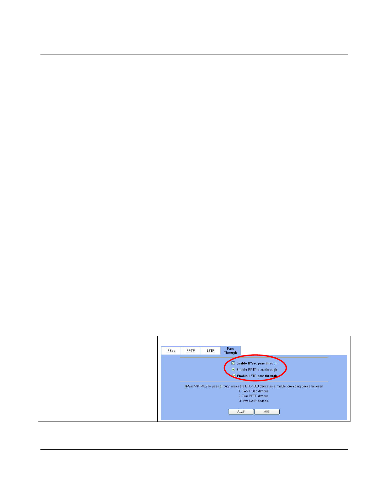
VPN Technical Introd uction DFL-1500 User M a nual
57
With the use of AH as the security protocol, protection is extended forward into the IP header to verify the integrity of the entire
packet by use of portions of the original IP header in the hashing process.
¾ Tunnel Mode
Tunnel mode encapsulates the entire IP packet to transmit it securely. A Tunnel mode is required for gateway services t o provide
access to internal system. Tunnel mode is f undamentally an IP tunnel with authentication and encryption. This is the most common
mode of operation. Tunnel mode is requ ired for gateway to gateway and host to gateway communications. Tunnel mode
communication have two sets of IP heade rs:
Outside header: The outside IP header contains the destination IP address of the VPN gateway.
Inside header: The inside IP header contains the destination IP address of the final system behind the VPN gateway.
The security protocol appears after the outer IP header and before the inside IP header.
9.1.7 IPSec Protocols
The ESP and AH protocols are necessary to create a Security Association (SA), the foundation of an IPSec VPN. An SA is built
from the authentication provided by AH and ESP protocols. The primary function of key management is to establish and maintain
the SA between systems. Once the SA is established, the transport of data may commence.
¾ AH (Authentication Header) Prot ocol
AH protocol (RFC 2402) was designed for integrity, authentication, sequenc e integrity (re play resistance), a nd non-repudiat ion but
not for confidentiality, for which the ESP was designed.
In applications where confidentia lity is not required or not sanctioned by government encryption restric tions, an AH can be
employed to ensure integrity. This typ e of implementation does not protect the information from dissemination but will allow for
verification of the integrity of the information and authentication of the originator.
¾ ESP (Encapsulating Security Payload) Protocol
The ESP protocol (RFC 2406) provides encryption as well as some of the services offered by AH. ESP authenticating properties are
limited compared to the AH due to the non-inclusion of the IP header information during the authentication process. However, ESP
is sufficient if only the upper layer protocols need to be authenticated.
An added feature of the ESP is payload padding, which further protects communications by concealing the size of the packet being
transmitted.
9.2 Make VPN packets pass through DFL-1500
Step 1 - Enable IPSec
If we need to setup DFL-1500 between the
existed IPSec / PPTP / L2TP connections. We
need to open up the Firewall blocking port of
DFL-1500 in advance. Here we provide a simple
way. You can through enable the IPSec / PPTP
/ L2TP pass through checkbox on this page.
Then the VPN connection s of IPSec / PPTP /
L2TP will pass through DFL-1500. As well as
DFL-1500 will play the middle forwarding device
role.
ADVANCED SETTI NG S > V PN S et t ings > Pass Throu gh
Page 64

Page 65
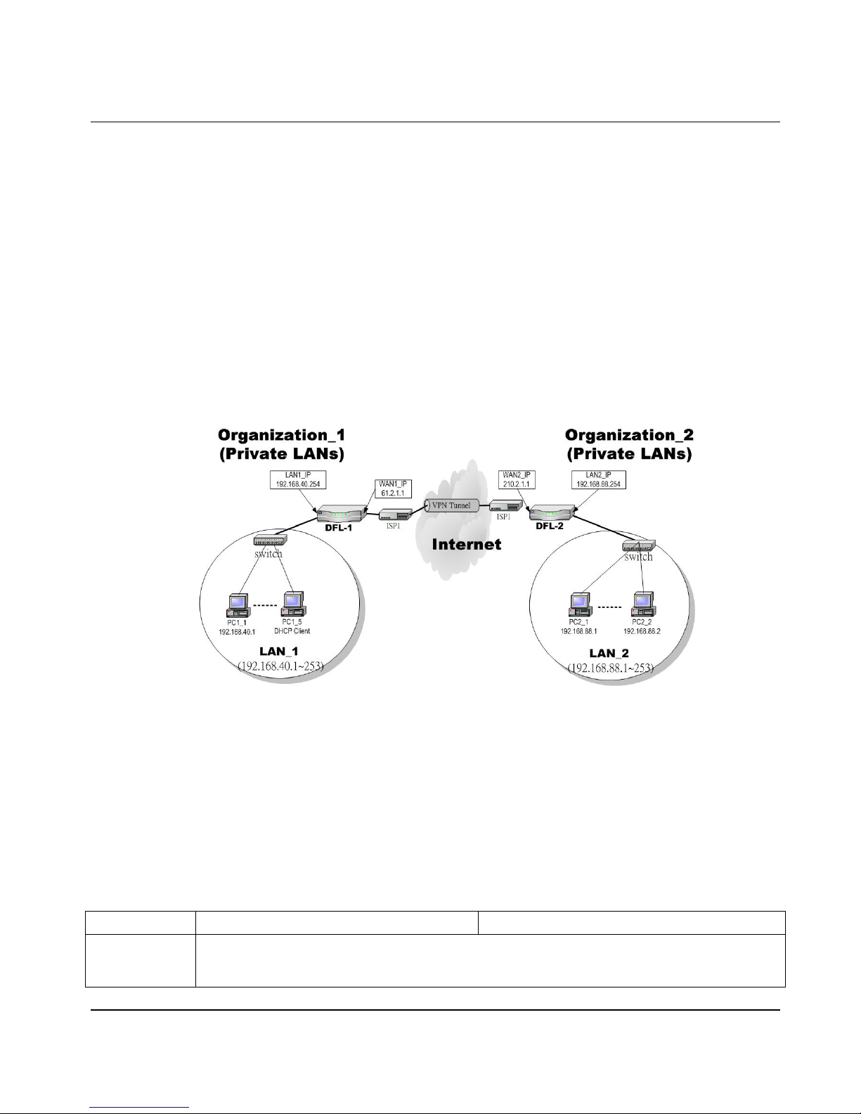
Virtual Priv ate Network – IPSec DFL-1500 User Manual
59
Chapter 10
Virtual Private Network – IPSec
This chapter introduces IPSec VPN and explains how to implement it.
As described in the Figure 2-1, we will extend to explain how to make a VPN link between LAN_1 and LAN_2 in this
chapter. The following Figure 10-1 is the real structure in our implemented process.
10.1 Demands
1. When a branch office subnet LAN_1 wants to connect with another branch office su bnet LAN_2 through th e public
Internet instead of the expensive private leased lines, VPN can provide encryption and authentication to secure the tunnel
that connects these two LANs.
Figure 10-1 Organization_1 LAN_1 is making VPN tunnel with Organization_2 LAN_2
10.2 Objectives
1. Let the users in LAN_1 and LAN_2 share the re sources through a secure channel established using the public Internet.
10.3 Methods
1. Separately configure DFL-1 and DFL-2 which are the edge gateways of LAN_1 and LAN_2 respectively. You have to
determine a key management method between IKE (Internet Key Exchange) and Manual Key. The following table
compares the settings between IKE and Manual Key. In the following, we will describe them separately.
IKE Manual Key
Same “Local Address” means the local LAN subnet; “Remote Address” means the remote LAN subnet; “My IP
Address” means the WAN IP address of the local VPN gateway while the “Security Gateway Address” means
the WAN IP address of the other VPN gateway.
Page 66
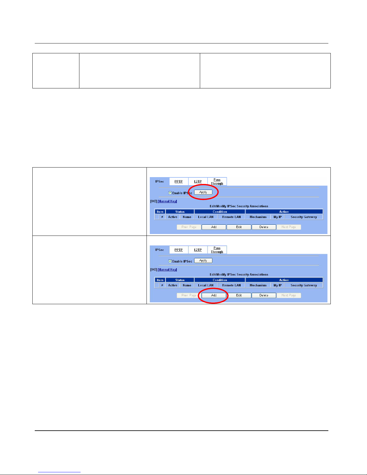
D-Link Part III
60
Difference The “Pre-Shared Key” must be the same at both
DFL-1500s.
The types and keys of “Encryption” and “Authenticate”
must be set the same on both DFL-1500s. However , the
“Outgoing SPI” at DFL-1 must equal to “Inc oming SPI”
at DFL-2, and the “Outgoing SPI” at DFL-2 must equal
to “Incoming SPI” at DFL-1.
Table 10-1 Compared IKE and Manual Key methods
10.4 Steps
In the following we will separately explain the ways to set up a secure DES/MD5 tunnel with IKE and Manual key.
¾ DES/MD5 IPSec tunnel: the IKE way
At DFL-1:
At the first, we will install the IPSec properties of DFL-1.
Step 1 - Enable IPSec
Check the Enable IPSec checkbox and click
Apply.
ADVANCED SETTINGS > VPN Settings > IPSec
Step 2 - Add an IKE rule
Click the IKE hyperlink and click Add to add a
new IPSec VPN tunnel endpoint.
ADVANC ED SETTING S > VPN Set t i n gs > I PSe c > IK E
Page 67
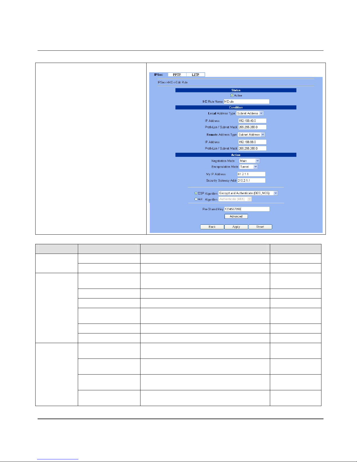
Virtual Priv ate Network – IPSec DFL-1500 User Manual
61
Step 3 - Customize the rule
Check the Active checkbox. Enter a name for
this rule like IKErule. Enter the Local IP
Address (192.168.40.0/255.255.255.0)
and the Remote IP Address
(192.168.88.0/255.255.255.0). Enter the
My IP Address as the public IP address of this
Firewall/VPN Router (61.2.1.1). Enter the
public IP of the opposite-side VPN gateway
(210.2.1.1) in the Security Gateway Addr.
Click the ESP Algorithm and select Encrypt
and Authenticate (DES, MD5). Enter the
Pre-Shared Key as 1234567890. Click the
Apply button to store the settings. Note, In the
Action region. It should choose either ESP
Algorithm or AH Algorithm, or system will
show error message. If you hope to set the
detailed item of IKE parameter. Click the
Advanced button in t his page. Otherw ise i t is ok to
just leave the value default.
ADVANCED SETTINGS > VPN Settings > IPSec > IKE > Add
FIELD DESCRIPTION EXAMPLE
Active This field will activate this IPSec policy rule enabled
Status
IKE Rule Name The name of this IPSec policy IKErule
Local Address Type
Determine the method to connect to the remote side of
VPN by using the local subnet or the local single host.
Subnet Address
IP Address The local IP address 192.168.40.0
Prefix Len/Subnet Mask The local IP Netmask 255.255.255.0
Remote Address Type
Determine the method to connect to the local side of VPN
by using the remote subnet or the remote single host.
Subnet Address
IP Address The remote IP addre ss 192.168.88.0
Condition
Prefix Len/Subnet Mask The remote IP Netmask 255.255.255.0
Negotiation Mode
Choose Main or Aggressive mode, see Chapter 9 for
details.
Main
Encapsulation Mode
Choose Tunnel or Transpor t mode, see Chap ter 9 for
details.
Tunnel
My IP Address
The IP address of local site DFL-1500 F irewall/VPN
Router
61.2.1.1
Action
Security Gateway Addr
The IP address of rem ote site device, like DFL-1500
Firewall/VP N Rou t er.
210.2.1.1
Page 68
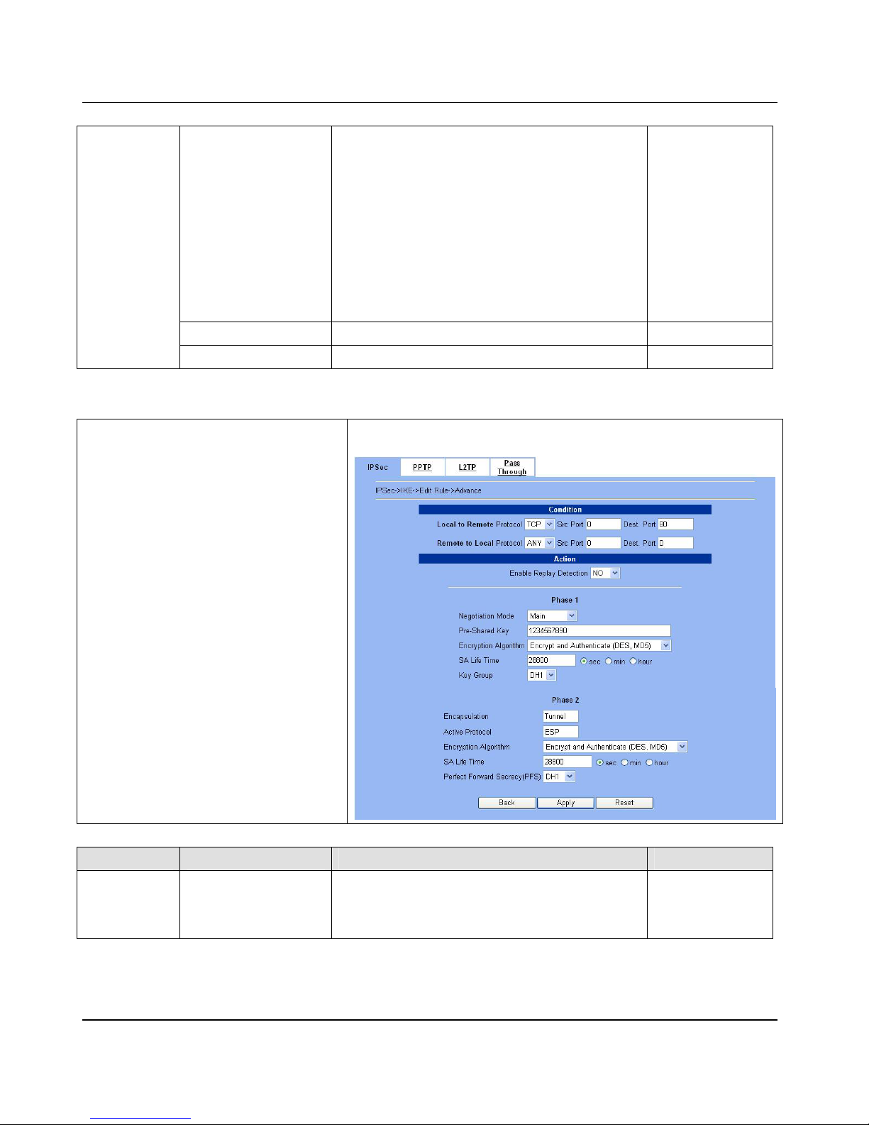
D-Link Part III
62
ESP Algorithm
ESP Algorithm may be grouped by the items of the
Encryption and Authentication Algorithms or execute
separately.
We can select below items, the Encryption and
Authentication Algor ith m combina tion or the below item
Authentication Algorithm singly.
Here Encryption Algorithms include
DES, 3DES and AES
Authentication Algorithms include
MD5 and SHA1
Encrypt and
Authenticate
(DES、MD5)
AH Algorithm Select Authentication Algorithm (MD5 or SHA1) disabled
Pre-Shared Key The key which is pre-shared with remote side. 1234567890
Table 10-2 Related field explanation of adding a IPSec policy rule
Step 4 - Detail settings of IPSec IKE
In this page, we will set th e detailed v alue of I KE
parameter. Fill in the related field as
Table 10-3
indicated to finish these settings.
ADVANCED SETTINGS > VPN Settings > IPSec > IKE > Add >
Advanced
FIELD DESCRIPTION EXAMPLE
Condition
Local to Remote Protocol
/ Src Port / Dest Port
Utilize this field to select some packets which are
destined for a specified port (Dest Port) or coming from
specified port (Src Port) can use IPSec feature. The
direction is fr o m l o c al to remote.
TCP / 0 / 80
Page 69
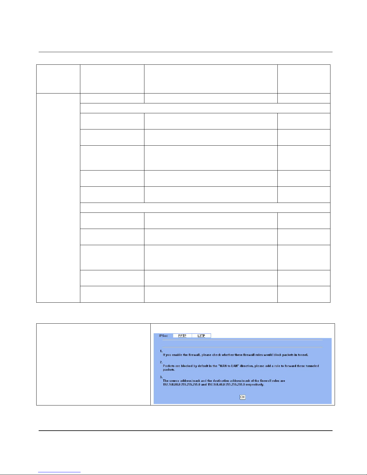
Virtual Priv ate Network – IPSec DFL-1500 User Manual
63
Remote to Local Protocol
/ Src Port / Dest Port
Utilize this field to select some pack ets which are
destined for specified port (Dest Port) or coming from
specified port (Src Port) can use IPSec feature. The
direction is from remote to local.
ANY / 0 / 0
Enable Replay Detection Whether is the “Replay Detection” enabled? NO
Phase1
Negotiation Mode
Choose Main or Aggressive mode, see Chapter 9 for
details.
Main
Pre-Shared Key
View only, it is set previously and can not be edited
again.
ESP
Encryption Algorithm Choose an encryption and authentication algorithm.
Encrypt and
Authenticate
(DES、MD5)
SA Life Time
Set the IKE SA lifetime. A value of 0 means IKE SA
negotiation never times out. See Chapter 9 for details.
28800 sec
Key Group
Choose a Diffie-Hellman public-key cryptography key
group
DH1
Phase2
Encapsulation
View only, it is set previously and can not be edited
again.
Tunnel
Active Prot o col
View only, it is set previously and can not be edited
again.
ESP
Encryption Algorithm Choose an encryption and authentication algorithm.
Encrypt and
Authenticate
(DES、MD5)
SA Life Time
Set the IPSec SA lifetime. A value of 0 means IKE SA
negotiation never times out. See Chapter 9 for details.
28800 sec
Action
Perfect Forward
Secrecy(PFS)
Enabling PFS means that the key is transient. This extra
setting will cause more security.
DH1
Table 10-3 Setup Advanced feature in the IPSec IKE rule
Step 5 - Remind to add a Firewal l rule
After finishing IPS e c rule s et ti ngs, we ne ed to add
a firewall rule. Here system shows a window
message to remind you of adding a firewall rule.
Just press the OK butt on to add a firewall rule.
ADVANCED SETTINGS > VPN Settings > IPSec > IKE > Add
Page 70
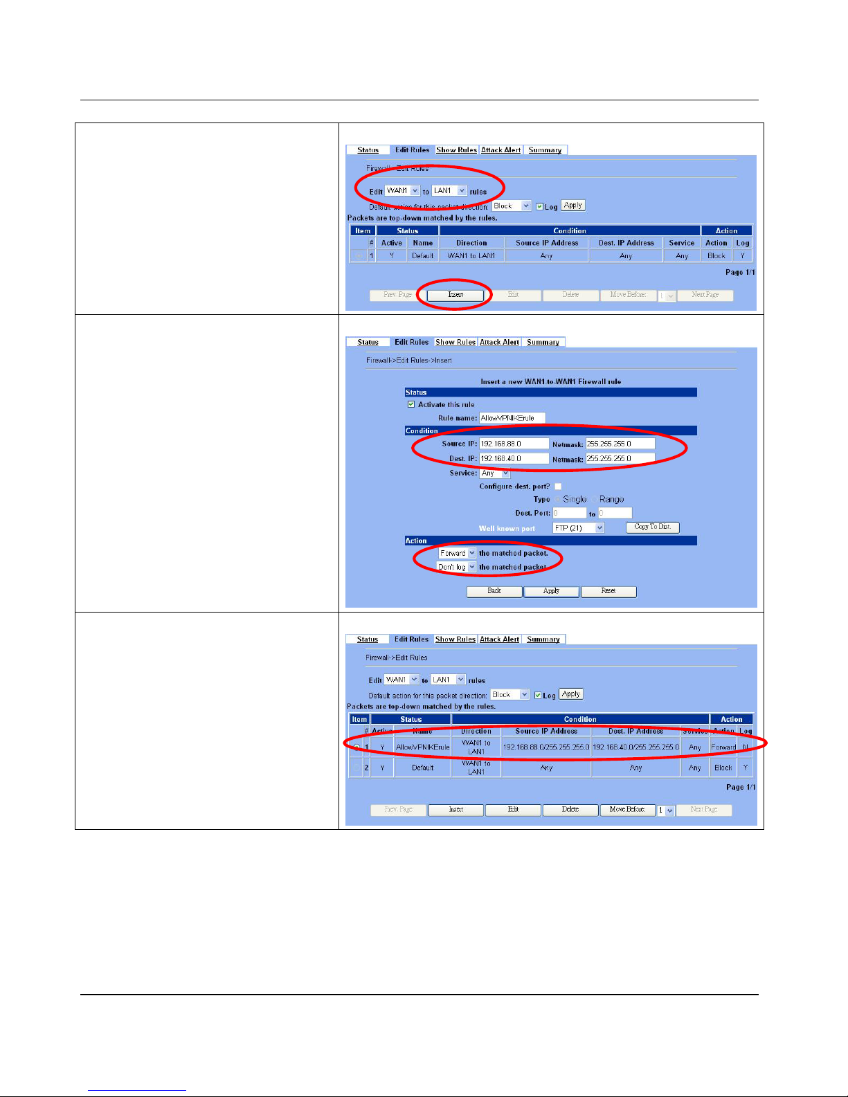
D-Link Part III
64
Step 6 - Add a Firewall rule
Beforehand, please make sure that the Firewall is
enabled. Select WAN1-to-LAN1 to display the rul es
of this direction. The default action of this
direction is Block with Logs. We have to allow
the VPN traffic from the WAN1 side to enter our
LAN1 side. So we click the Insert button to add
a Firewall rule before the default rule.
ADVANCED SETTINGS > Firewall > Edit Rules
Step 7 - Customize the Firewall rule
Check the Activate this rule. Enter the
Rule Name as AllowVPNIKErule, Source IP
as 192.168.88.0, and Dest. IP as
192.168.40.0. Click Apply to store this rule.
ADVANCED SETTINGS > Firewall > Edit Rules > Insert
Step 8 - View the r esu l t
Here we have a new rule before the default
firewall rule. This rule will allow packets from
192.168.88.0 / 255.255.255.0 pass through
DFL-1500. And accomplish the VPN tunnel
establishment.
ADVANCED SETTINGS > Firewall > Edit Rules
At DFL-2:
Here we will install the IPSec properties of DFL-2. Note that the “Local Address” and “Remote address” field are opposite to
the DFL-1, and so are “My IP Address” and “Security Gateway Addr” field.
Page 71
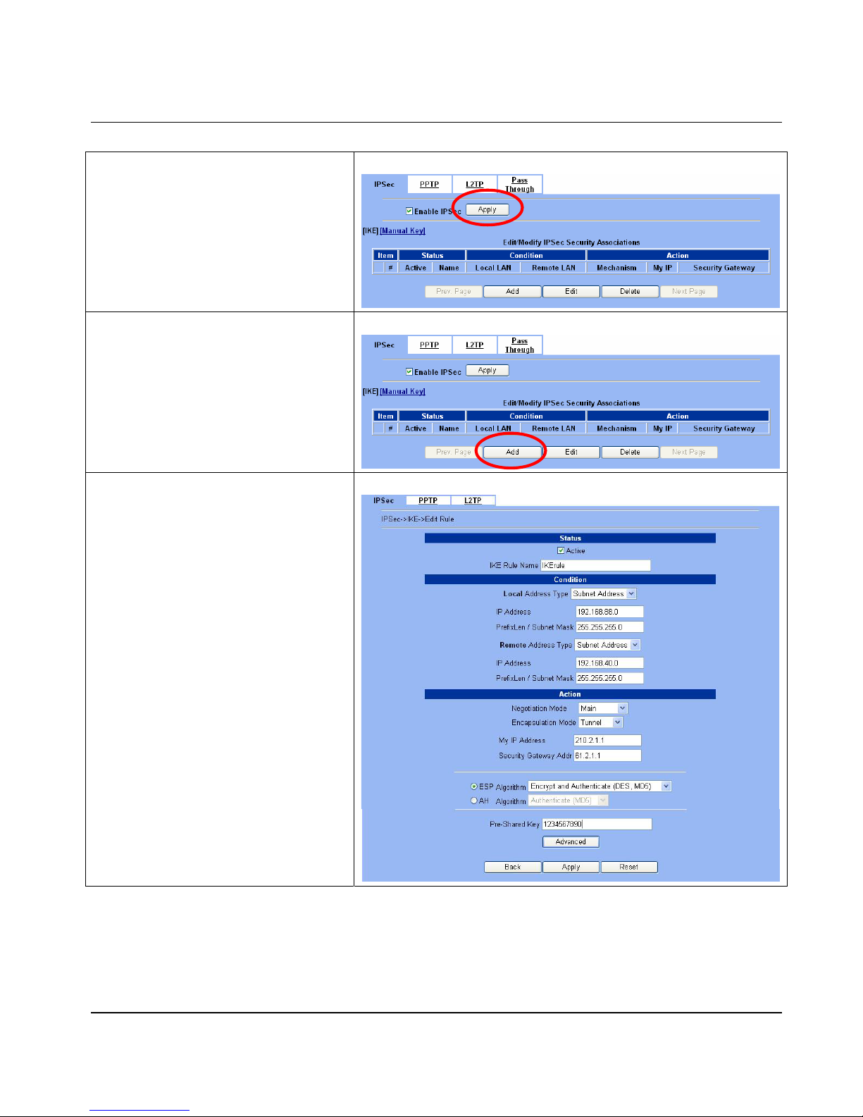
Virtual Priv ate Network – IPSec DFL-1500 User Manual
65
Step 1 - Enable IPSec
Check the Enable IPSec checkbox and click
Apply.
ADVANCED SETTINGS > VPN Settings > IPSec
Step 2 - Add an IKE rule
Click the IKE hyperlink and click Add to add a
new IPSec VPN tunnel endpoint.
ADVANCED SETTINGS > VPN Settings > IPSec > IKE
Step 3 - Customize the rule
Check the Active checkbox. Enter a name for
this rule like IKErule. Enter the Local IP
Address (192.168.88.0/255.255.255.0)
and the Remote IP Address
(192.168.40.0/255.255.255.0). Enter the
My IP Address as the public IP address of this
Firewall/VPN Router (210.2.1.1). Enter the
public IP of the opposite-side VPN gateway
(61.2.1.1) in the Security Gateway Addr.
Click the ESP Algorithm and select Encrypt
and Authenticate (DES, MD5). Enter the
Pre-Shared Key as 1234567890. Click the
Apply button to store the settings. Note, in the
Action region, you should choose either ESP
Algorithm or AH Algorithm, or system will show
error message.
ADVANCED SETTINGS > VPN Settings > IPSec > IKE > Add
Page 72
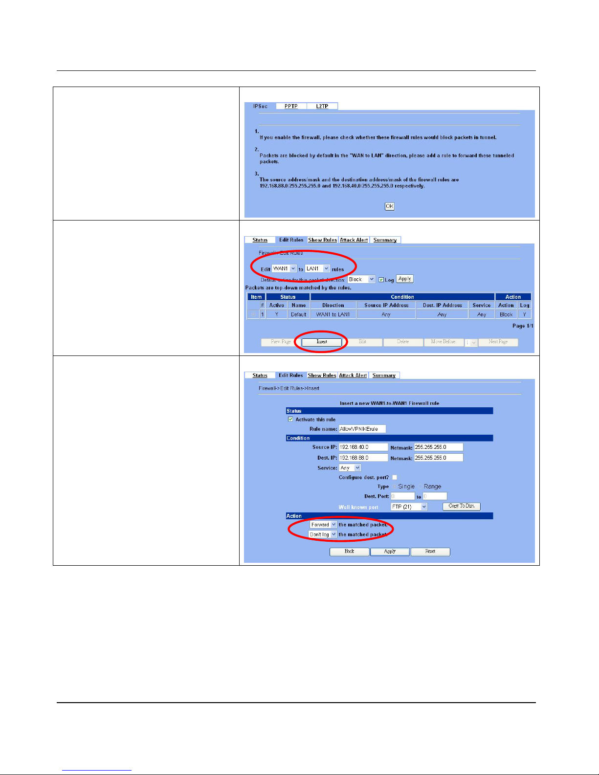
D-Link Part III
66
Step 4 - Remind to add a Firewall rule
After finishing IPSec rule settings, w e need to add
a firewall rule. Here system shows a window
message to remind you of adding a firewall rule.
Just press the OK button to add a firewall rule.
ADVANCED SETTINGS > VPN Settings > IPSec > IKE > Add
Step 5 - Add a Firewall rule
Same as at DFL-1. We need to add an extra
firewall rule to allow IPSec pack ets to come from
internet. So here we select WAN1-to-LAN1
direction, and click Insert button.
ADVANCED SETTINGS > Firewall > Edit Rules
Step 6 - Customize the Firewall rule
Check the Activate this rule. Enter the
Rule Name as AllowVPNIKErule, Source IP
as 192.168.40.0, and Dest. IP as
192.168.88.0. Click Apply to store this rule.
ADVANCED SETTINGS > Firewall > Edit Rules > Insert
Page 73
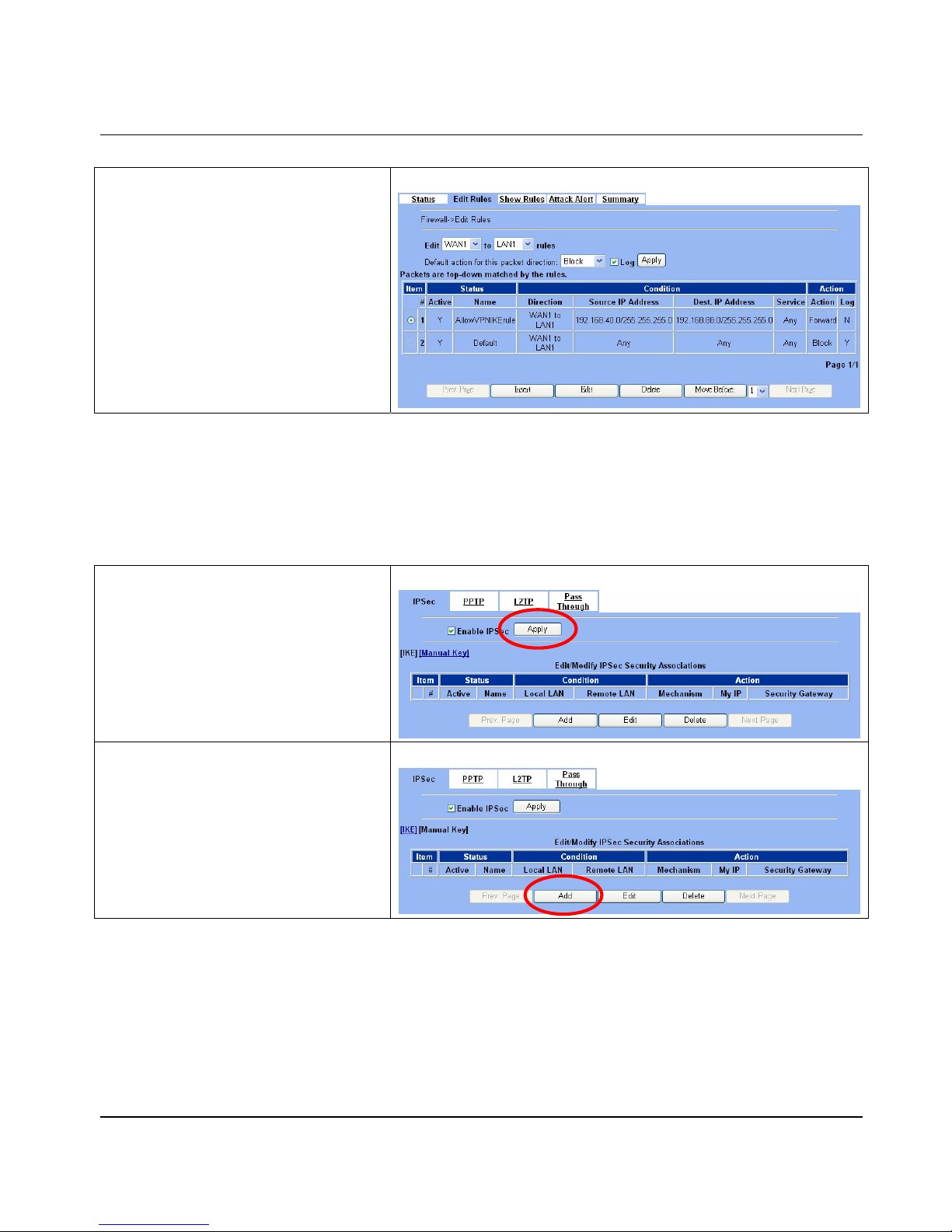
Virtual Priv ate Network – IPSec DFL-1500 User Manual
67
Step 7 - View the result
Now we have inserted a new rule before the
default firewall rule. Any packets from
192.168.40.0/24 to 192.168.88.0/24 will
be allowed to pass through the DFL-1500 and
successfully access the 192.168.88.0/24
through the VPN tunnel .
ADVANCED SETTINGS > Firewall > Edit Rules
¾ DES/MD5 IPSec tunnel: the Manual-Key way
In the previous sec tion, we have introduced IKE method. Here we will introduce another method using Manual-Key way
instead of IKE to install DFL-1.
At DFL-1:
At the first, we will use the Manual-Key way to install the IPSec properties of DFL-1.
Step 1 - Enable IPSec
Check the Enable IPSec checkbox and click
Apply.
ADVANCED SETTINGS > VPN Settings > IPSec
Step 2 - Add a Manual Key rule
Click the Manual Key hyperlink and click Add to
add a new IPSec VPN tunnel endpoint.
ADVANCED SETTINGS > VPN Settings > IPSec > Manual Key
Page 74
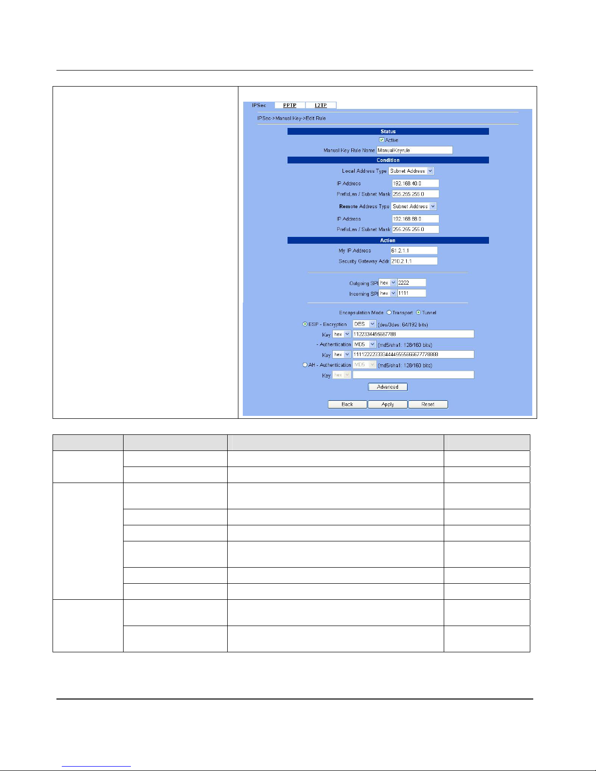
D-Link Part III
68
Step 3 - Customize the rule
Same as those in IKE. But there is no pre-shared
key in the manual-key mode. Enter the Key for
encryption, such as 1122334455667788. Enter
the Key for authentication, such as
11112222333344445555666677778888.
Additionally, the Outgoing SPI and Incoming
SPI have to be manually specified. Enter 2222
and 1111 respectively to the Outgoing SPI and
the Incoming SPI. Click Apply to store the rul e.
ADVANCED SETTINGS > VPN Settings > IPSec > Manual Key > Add
FIELD DESCRIPTION EXAMPLE
Active This field will activate this IPSec policy rule enabled
Status
Manual Key Rule Name The name of this IPSec policy ManualKeyrule
Local Address Type
Determine the method to connect to the remote side of
VPN by using the local subnet or the local single host.
Subnet Address
IP Address The local IP address 192.168.40.0
Prefix Len/Subnet Mask The local IP Netmask 255.255. 255.0
Remote Address Type
Determine the method to connect to the local side of VPN
by using the remote subnet or the remote single host.
Subnet Address
IP Address The remote IP addre ss 192.168.88.0
Condition
Prefix Len/Subnet Mask The remote IP Netmask 255.255.255.0
My IP Address
The IP address of local site DFL-1500 Firewall/VPN
Router
61.2.1.1
Action
Security Gateway Addr
The IP address of remote site device, like DFL-1500
Firewall/VPN Router.
210.2.1.1
Page 75
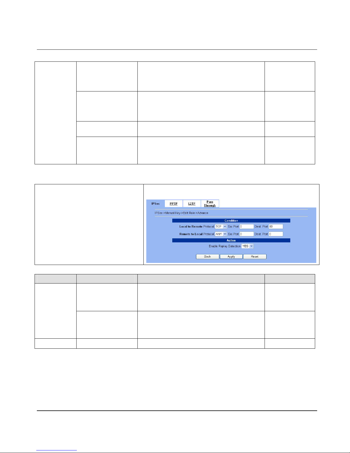
Virtual Priv ate Network – IPSec DFL-1500 User Manual
69
Outgoing SPI
The Outgoing SPI (Security Parameter Index) value.
Notice:HEX SPI must be a value between 600 and
600000.Or DEC SPI must be a value between 1500 and
6300000.
2222
Incoming SPI
The Incoming SPI (Security Parameter Index) value.
Notice:HEX SPI must be a value between 600 and
600000.Or DEC SPI must be a value between 1500 and
6300000.
1111
Encapsulation Mode
Choose Tunnel or Transpor t mode, see Chap ter 9 for
details.
Tunnel
ESP – Encryption /
Authentication or
AH - Authentication
Select the Encryption (DES or 3DES) and Authentication
(MD5 or SHA1) Algorithm combination. And enter the
key either hex or string format separately.
ESP – Encrypti on
(DES) /
Authentication
(MD5)
Table 10-4 Add a IPSec Manual Key rule
Step 4 - Detail settings of IPSec Manual
Key
For the detailed setting in the Manual Key. We
can press the Advanced button in the previous
page. Then set the parameter separatel y.
ADVANCED SETTINGS > VPN Settings > IPSec > Manual Key > Add
> Advanced
FIELD DESCRIPTION EXAMPLE
Local to Remote Protocol
/ Src Port / Dest Port
Use this field to select some packets which are destined
for specified port (Dest Port) or coming from specified
port (Src Port) can use IPSec feature. The direction is
from local to remote.
TCP / 0 / 80
Condition
Remote to Local Protocol
/ Src Port / Dest Port
Use this field to select some packets which are destined
for specified port (Dest Port) or coming from specified
port (Src Port) can use IPSec feature. The direction is
from remote to local.
ANY / 0 / 0
Action
Enable Replay Detection
Whether is the “Replay Detection” enabled? YES
Table 10-5 Setup Advanced feature in the IPSec Manual Key rule
Page 76
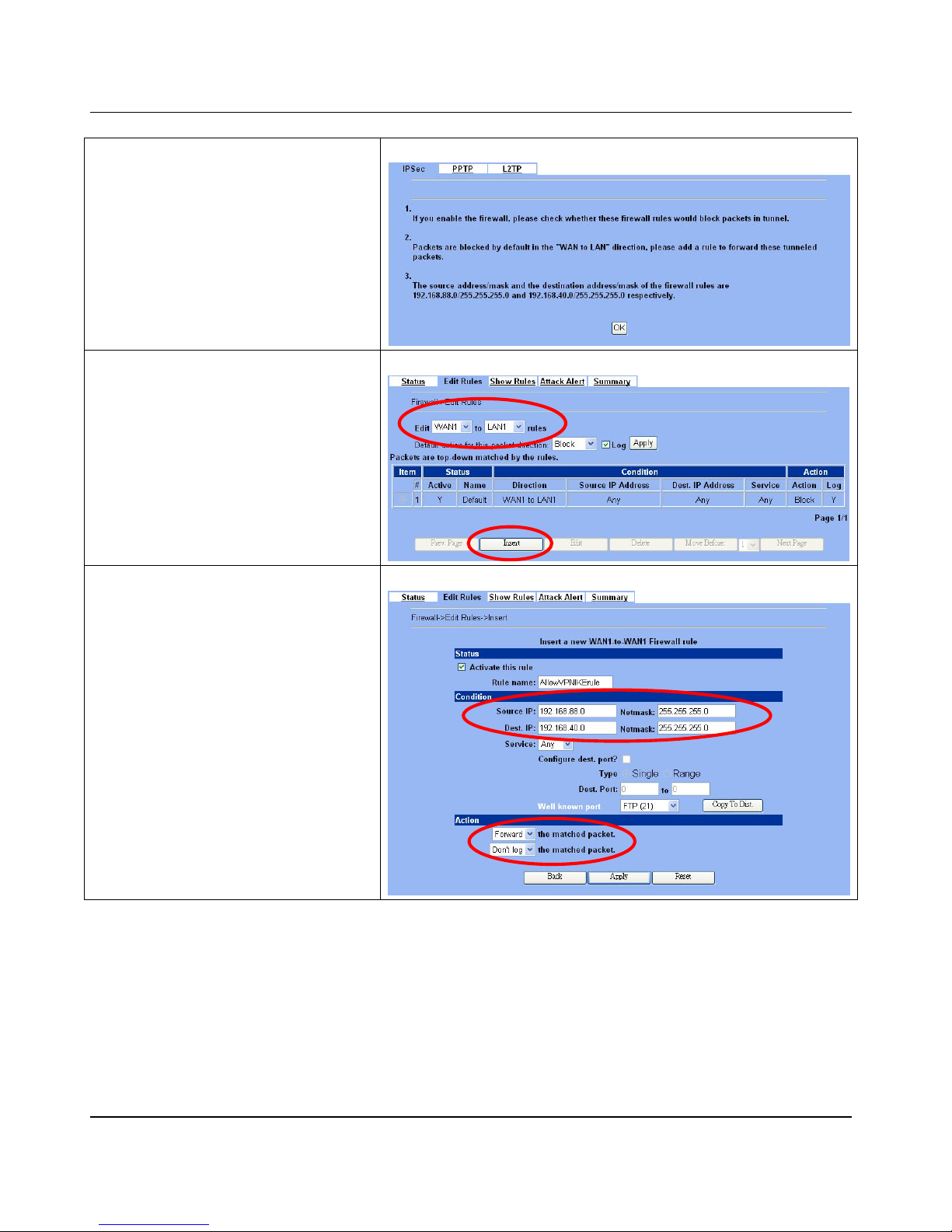
D-Link Part III
70
Step 5 - Remind to add a Firewall rule
After finishing IPSec rule settings, w e need to add
a firewall rule. Here system shows a window
message to remind you of adding a firewall rule.
Just press the OK button to add a firewall rule.
ADVANCED SETTINGS > VPN Settings > IPSec > Manual Key > Add
Step 6 - Add a Firewall rule
Same as that in IKE method. Please make sure
that the Firewall is enabled. Select WAN1-to-LAN1
to display the rules of this direction. The default
action of this direction is Block with Logs. W e
have to allow the VPN traffic from the WAN1 side
to enter our LAN1 side. So we click the Insert
button to add a Firewall rule before the default
rule.
ADVANCED SETTINGS > Firewall > Edit Rules
Step 7 - Customize the Firewall rule
Check the Activate this rule. Enter the
Rule Name as AllowVPNIKErule, Source IP
as 192.168.88.0, and Dest. IP as
192.168.40.0. Click Apply to store this rule.
ADVANCED SETTINGS > Firewall > Edit Rules > Insert
Page 77
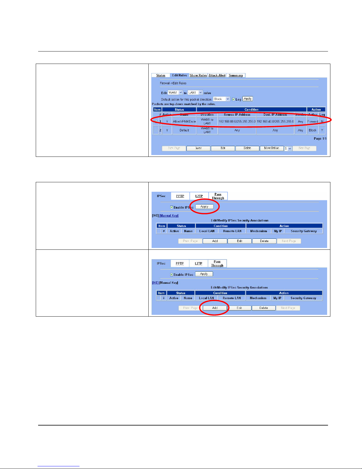
Virtual Priv ate Network – IPSec DFL-1500 User Manual
71
Step 8 - View the result
Here we have a new rule before the default
firewall rule. This rule will allow packets from
192.168.88.0 / 255.255.255.0 pass through
DFL-1500. And accomplish the VPN tunnel
establishment.
ADVANCED SETTINGS > Firewall > Edit Rules
At DFL-2:
Second, we will use the Manual-Key way to install the IPSec properties of DFL-1.
Step 1 - Enable IPSec
Check the Enable IPSec checkbox and click
Apply.
ADVANCED SETTINGS > VPN Settings > IPSec
Step 2 - Add a Manual Key rule
Click the Manual Key hyperlink and click Add to
add a new IPSec VPN tunnel endpoint.
ADVANCED SETTINGS > VPN Settings > IPSec > Manual Key
Page 78
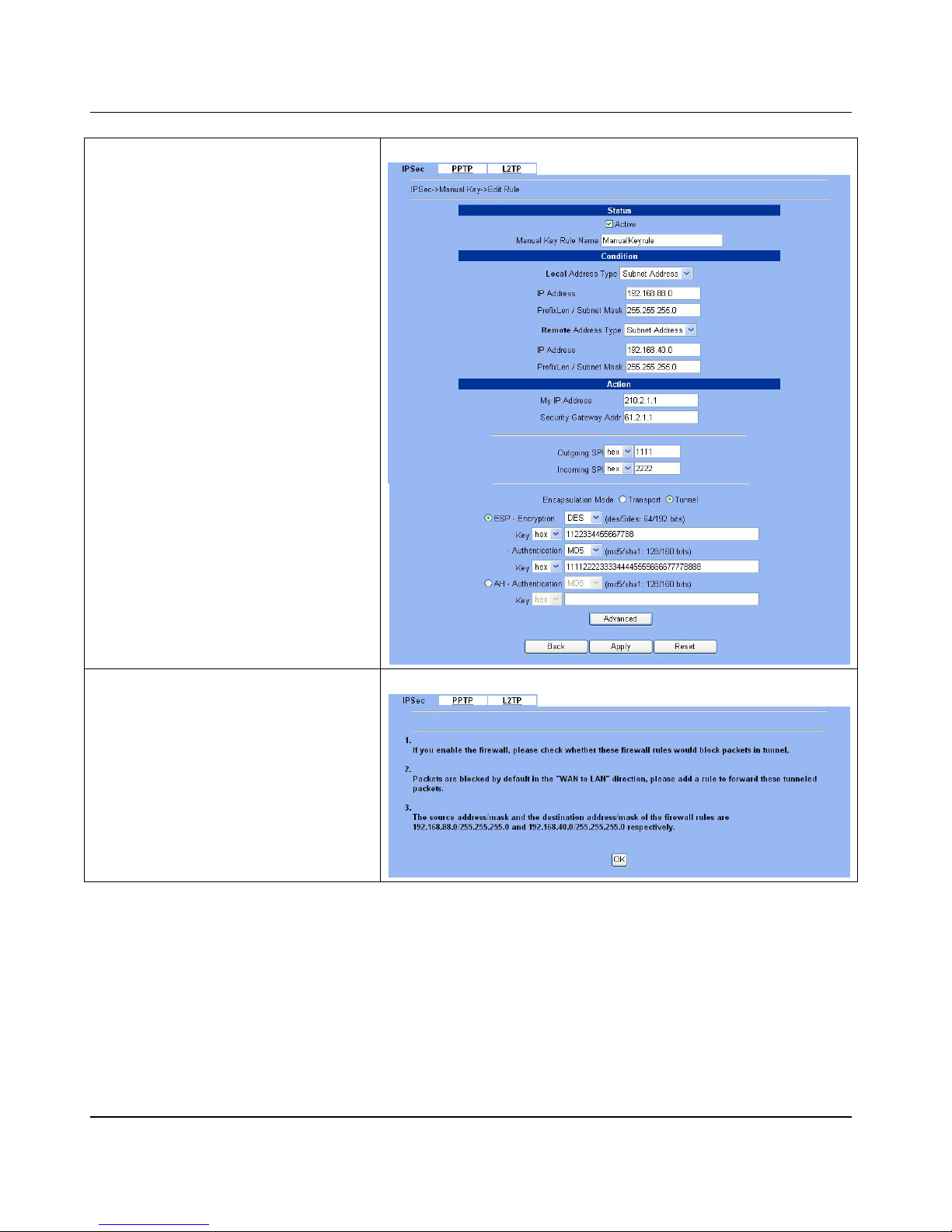
D-Link Part III
72
Step 3 - Customize the rule
Similar to those in DFL-1, except that you should
interchange the Local IP Address with the
Remote IP Address, the My IP Address with
the Security Gateway Addr., and the
Outgoing SPI with the Incoming SPI.
ADVANCED SETTINGS > VPN Settin gs > IPSec > Manual Ke y > Add
Step 4 - Remind to add a Firewall rule
After finishing IPSec rule settings, we need to add
a firewall rule. Here system shows a window
message to remind you of adding a firewall rule.
Just press the OK button to add a firewall rule.
ADVANCED SETTINGS > VPN Settings > IPSec > Manual Key > Add
Page 79
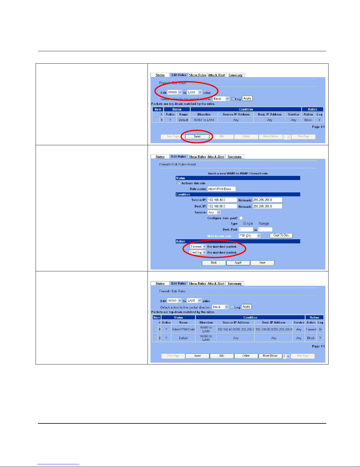
Virtual Priv ate Network – IPSec DFL-1500 User Manual
73
Step 5 - Add a Firewall rule
Same as that in IKE method. Please make sure
that the F ire wal l is enab le d. Selec t WAN1-to-LAN1
to display the rules of this direction. The default
action of this direction is Block with Logs. We
have to allow the VPN traffic from the WAN1 side
to enter our LAN1 side. So we click the Insert
button to add a Firewall rule before the default
rule.
ADVANCED SETTINGS > Firewall > Edit Rules
Step 6 - Customize the Firewall rule
Check the Activate this rule. Enter the
Rule Name as AllowVPNIKErule, Source IP
as 192.168.40.0, and Dest. IP as
192.168.88.0. Click Apply to store thi s rule.
ADVANCED SETTINGS > Firewall > Edit Rules > Insert
Step 7 - View the result
Now we have inserted a new rule before the
default firewall rule. Any packets from
192.168.40.0/24 to 192.168.88.0/24 will
be allowed to pass through the DFL-1500 and
successfully access the 192.168.88.0/24
through the VPN tunnel .
ADVANCED SETTINGS > Firewall > Edit Rules
Page 80

Page 81
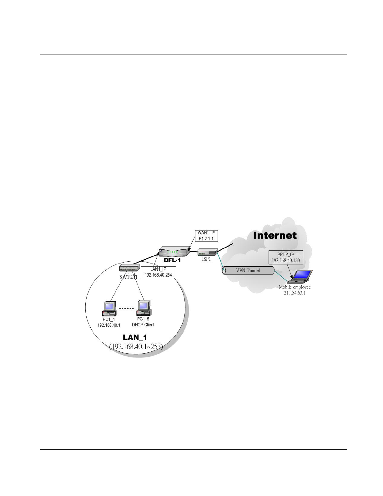
Virtual Private Network – PPTP DFL-1500 User Manual
75
Chapter 11
Virtual Private Network – PPTP
This chapter introduces PPTP and explains how to implement it.
11.1 Demands
1. One employee in our company may sometimes want to connect back to our coporate network to work on something. His
PC is PC1_1 in LAN_1 instead of DMZ_1 so he cannot directly access the host by simply with virtual server settings. This
causes inconvenience for the employee to work remotely.
2. In our branch office, we need to provide PPTP connection methods to connect back to headquater for the internal company
employees.
11.2 Objectives
1. With PPTP tunneling, emulate the mobile employee as a member in LAN1 after he dials in the corporate network. Then he
can access all computers in LAN_1 just as if he stays in the office covered by LAN1.
2. Make sure every employee in the branch office can use the network resource in the headquater. Suppose they are in the
same internal network, and keep the communication security.
Figure 11-1 PPTP method connection
11.3 Methods
1. Setup the PPTP serv er at DFL-1500. Setup the remote PC as the PPTP client. After dialing up to DFL-1, DFL-1 will assign
a private IP which falls in the range of the settings in the PPTP server at DFL-1. Suppose the range is defined as
192.168.40.180 ~ 192.168.40.199, the remote host may get an IP of 192.168.40.180 and logica lly become a member in
LAN1.
2. Setup the DFL-1500 as the PPTP client. Let all the client PCs behind the DFL-1500. They can connect to the network
behind PPTP Server by passing throug h DFL-1500. It sounds like no Internet ex ists but can connect with each other.
Page 82
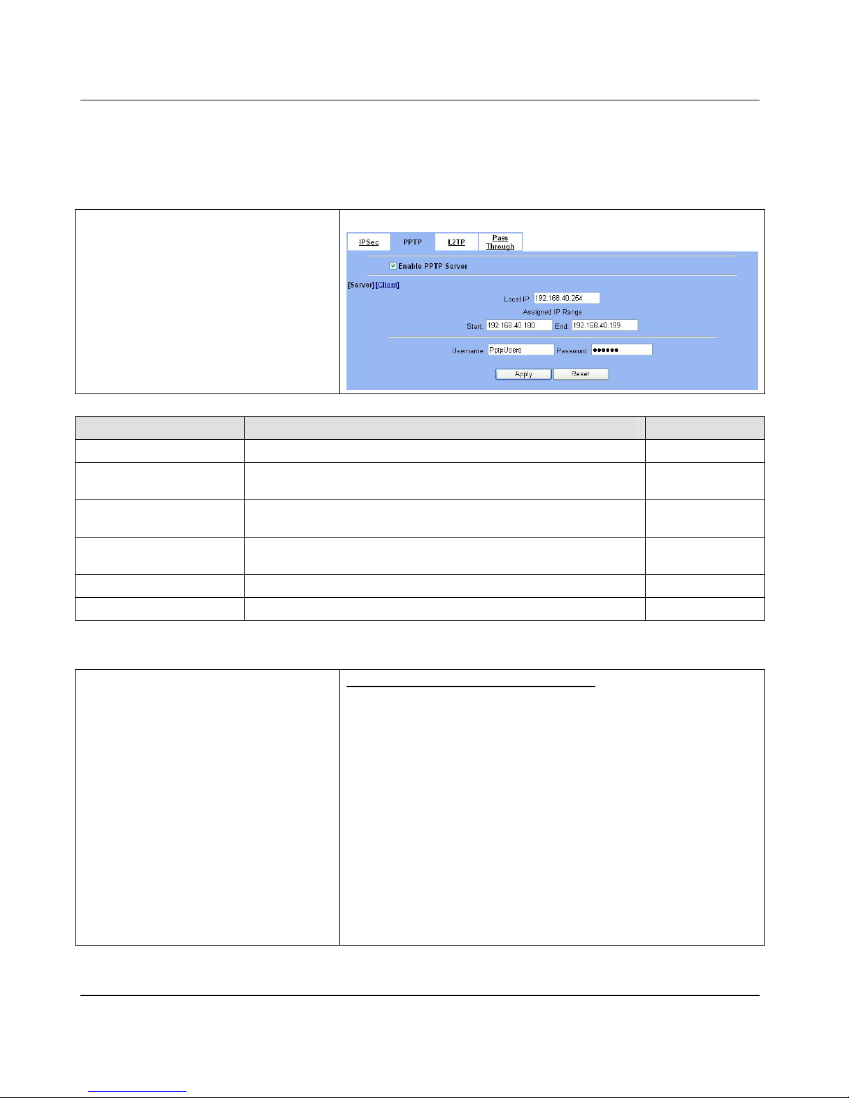
D-Link Part III
76
11.4 Steps
11.4.1 Setup PPTP Network Server
Step 1 – Ena bl e PPT P Ser ve r
Check the Enable PPTP checkbox, enter the
LAN1_IP of the DFL-1(192.168.40.254) in the
Local IP, and enter the IP range that will be
assigned to the PPTP clients in the Start IP
and the End IP fields.
Enter the Username
and Password that will be used by the
employees during dial-up. C
lick the Apply to
finish configurations.
ADVANCED SETTINGS > VPN Settings > PPTP
FIELD DESCRIPTION EXAMPLE
Enable PPTP Server Enable PPTP feature of the DFL-1500 enabled
Local IP
The Local IP is the allocated IP address in the internal Network after PPTP
client dials in the DFL-1500.
192.168.40.254
Start IP
The Start IP is the allocated starting IP address in the internal network after
PPTP client dials in the DFL-1500.
192.168.40.180
End IP
The End IP is the allocated ending IP address in the internal network after
PPTP client dials in the DFL-1500.
192.168.40.199
Username The account which allow PPTP client user to dial in DFL-1500. PptpUsers
Password The password which allow PPTP client user to dial in DFL-1500. Dif3wk
Table 11-1 Setup PPTP Server
Step 2 – Setup Windows XP/2000 PPTP
clients
Configur ing A P PTP Dial-U p Connection
1. Configuring a PPTP dial-up connection
2. Go to Start > Control Panel > Network and Internet
Connections > Make new connection.
3. Select Create a connection to the network of your
workplace and select Next.
4. Select Virtual Private Network Connection and select Next.
5. Give a Name the connection and select Next.
6. If the Public Network dialog box appears, choose the Don’t dial
up initial connection and select Next.
7. In the VPN Server Selection dialog, enter the public IP or
hostname of the DFL-1500 to connect to and select Next.
8. Set Connection Availability to Only for myself and select
Next.
9. Select Finish.
Page 83
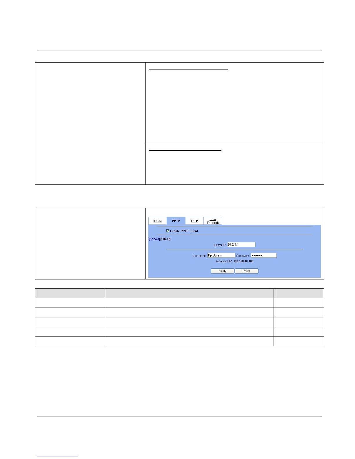
Virtual Private Network – PPTP DFL-1500 User Manual
77
Customize the VPN Connection
1. Right-click the icon that you have created.
2. Select Properties > Security > Advanced > Settings.
3. Select No Encryption from the Data Encryption and click Apply.
4. Select the Properties > Networking tab.
5. Select PPTP VPN from the VPN Type.
Make sure the following are selected:
TCP/IP
QoS Packet Scheduler
6. Select Apply.
Connecting to the PPTP VPN
1. Connect to your ISP.
2. Start the dial-up connection configured in the previous procedure.
3. Enter your PPTP VPN User Name and Password.
4. Select Connect.
11.4.2 Setup PPTP Network Client
Step 1 – Enable PPTP Client
Fill in the IP address of PPTP Server and
allocates Username/Password. When connecting
to the PPTP Server succe ss fully, it will appear the
allocated IP address for the PPTP client in the
“Assigned IP” field.
ADVANCED SETTINGS > VPN Settings > PPTP > Client
FIELD DESCRIPTION EXAMPLE
Enable PPTP Client Enable PPTP Client feature of DFL-1500 enabled
Server IP The IP address of P PTP server. 61.2.1.1
Username The designed account which allows PPTP client to dial in. PptpUsers
Password The designed password which allows PPTP client to dial in. Dif3wk
Assigned IP The allocated IP address when PPTP client connects to the PPTP server. 192.168.40.180
Table 11-2 Setup PPTP Client setting s
Page 84

Page 85
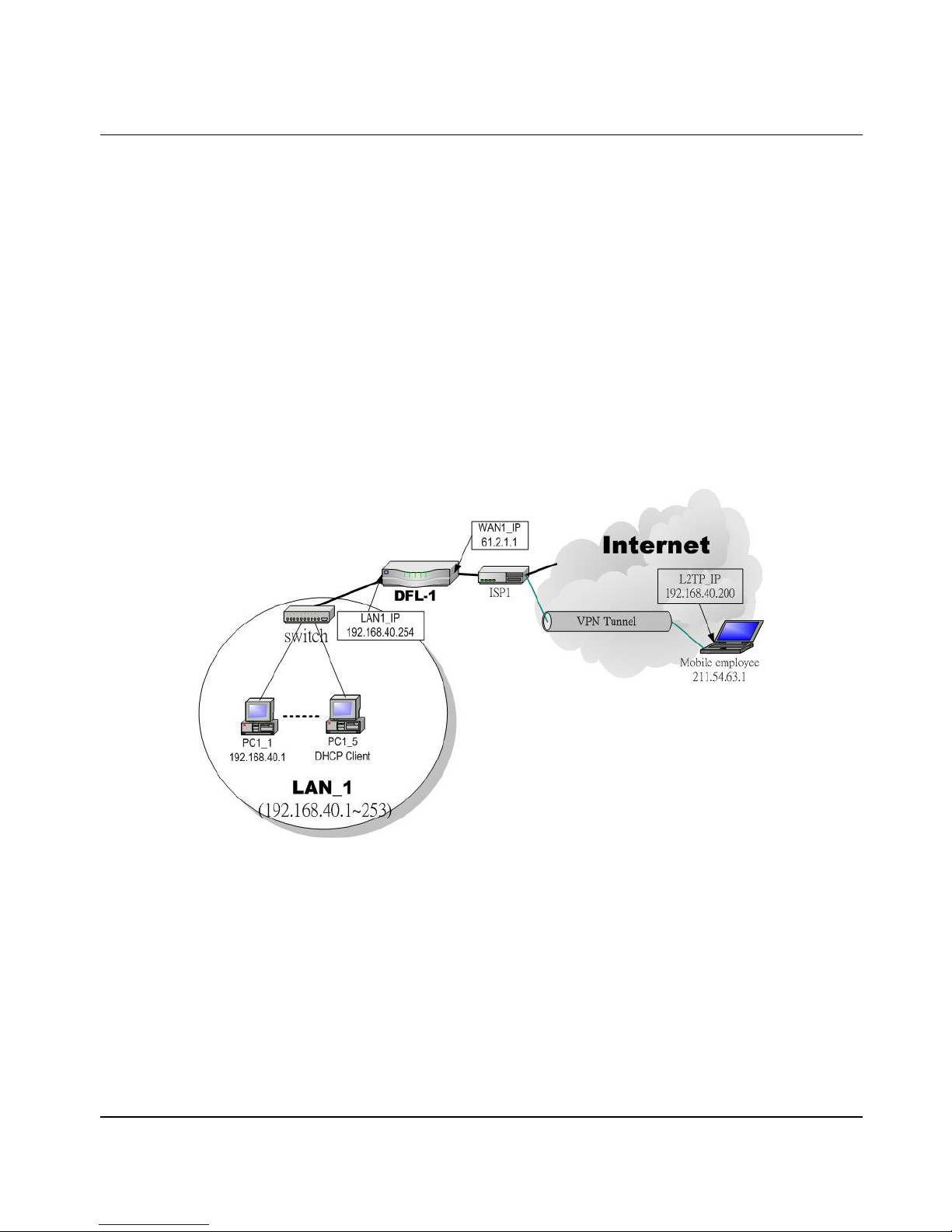
Virtual Private Network – L2TP DFL-1500 User Manual
79
Chapter 12
Virtual Private Network – L2TP
This chapter introduces L2TP and explains how to implement it.
12.1 Demands
1. One employee in our company may sometimes want to connect back to our coporate network to work on something. His
PC is PC1_1 in LAN1 instead of DMZ1 so he cannot directly access the host by simply with virtual server settings. This
causes inconvenience for the employee to work remotely.
12.2 Objectives
1. With L2TP tunneling, emulate the mobile employee as a member in LAN_1 after he dials in the corporate network. Then
he can access all computers in LAN_1 just as if he stays in the office covered by LAN_1.
Figure 12-1 L2TP method connection
12.3 Methods
1. Setup the L2TP server at DFL-1500 (LNS: L2TP Network Server ). After dialing up to DFL-1500, DFL-1500 will assign a
private IP which fa lls in the range of the s ettings in the L2TP server at DFL-1500. Suppose the range is defined as
192.168.40.200 ~ 192.168.40.253, the remote host may get an IP of 192.168.40.200 and logically become a member in
LAN_1.
Page 86
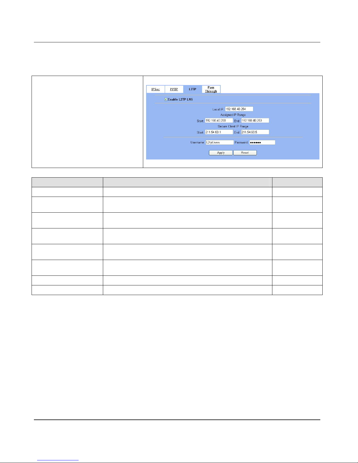
D-Link Part III
80
12.4 Steps
12.4.1 Setup L2TP Network Server
Step 1 – Ena bl e L2TP LN S
Check the Enable L2TP LNS checkbox, enter
the LAN1_IP of the DFL-1 (192.168.40.254)
in the Local IP, and enter the IP range that will
be assigned to the L2TP clients in the Start IP
and the End IP fields. Enter the IP range in the
LAC Start IP and the LAC End IP that will cover
the real IP of the remote users. In our case, since
the employee uses
211.54.63.1 so we can
fill 211.54.63.1~211.54.63.5 to cover
211.54.63.1. Enter the Username and
Password that will be used by the
employees during dial-up. C
lick the Apply to
finish configurations.
ADVANCED SETTINGS > VPN Settings > L2TP > LNS
FIELD DESCRIPTION EXAMPLE
Enable L2TP LNS Enable L2TP LNS feature of DFL-1500 enabled
Local IP
The Local IP is the allocated IP address in the internal network after default
gateway of L2TP client dials in the DFL-1500.
192.168.40.254
Start IP
The Start IP is the allocated starting IP address in the internal network after
L2TP client dials in the DFL-1500.
192.168.40.200
End IP
The End IP is the allocated ending IP address in the internal network after
L2TP client dials in the DFL-1500.
192.168.40.253
LAC Start IP
The IP address starting range which is allowed user to dial in LNS server by
using L2TP protocol.
211.54.63.1
LAC End IP
The IP address ending range which is allowed user to dial in LNS server by
using L2TP protocol.
211.54.63.5
Username The account which allows L2TP client user to dial in DFL-1500. L2tpUsers
Password The password which allows L2TP client user to dial in DFL-1500. Dif3wk
Table 12-1 Setup L2TP LNS Server settings
Page 87

Virtual Private Network – L2TP DFL-1500 User Manual
81
Configuring A L2TP Dial -Up Con nect i on
1. Configure a L2TP dial-up connection
2. Go to Start > Control Panel > Network and Internet
Connections > Make new connection.
3. Select Create a connection to the network of your
workplace and select Next.
4. Select Virtual Private Network Connection and select Next.
5. Give a Name the connection and select Next.
6. If the Public Network dialog box appears, choose the Don’t dial
up initial connection and select Next.
7. In the VPN Server Selection dialog, enter the public IP or
hostname of the DFL-1500 to connect to and select Next.
8. Set Connection Availability to Only for myself and select
Next.
9. Select Finish.
Customize the VPN Connection
1. Right-click the icon that you have created.
2. Select Properties > Security > Advanced > Settings.
3. Select No Encryption from the Data Encryption and click Apply.
4. Select the Properties > Networking tab.
5. Select L2TP VPN from the VPN Type.
Make sure the following are selected:
TCP/IP
QoS Packet Scheduler
6. Select Apply.
Step 2 – Setup Windows XP/2000 L2TP
clients
Editing Window s Registry
The default Windows 2000 L2TP traffic policy does not allow L2TP traffic
without IPSec encryption. You can disable default behavior by editing the
Windows 2000 Registry as described in the following steps. Please refer
to the Microsoft documentation for editing the Windows Registry.
1. Use the registry editor (regedit) to locate the following key in the
registry: HKEY_LOCAL_MACHINE \ System \ CurrentControlSet \
Services \ Rasman \ Parameters
2. Add the following registry value to this key:
• Value Name: ProhibitIpSec
• Data Type: REG_DWORD
• Value: 1
3. Save your changes and restart the computer.
You must add the ProhibitIpSec registry value to each Windows
2000-based endpoint computer of an L2TP or IPSec connection to
prevent the automatic filter for L2TP and IPSec traffic from being created.
When the ProhibitIpSec registry value is set to 1, your Windows
2000-based computer does not create the automatic filter that uses CA
authentication. Instead, it checks for a local or Active Directory IPSec
policy.
Page 88

D-Link Part III
82
Connecting to the L2TP VPN
1. Connect to your ISP.
2. Start the dial-up connection configured in the previous procedure.
3. Enter your L2TP VPN User Name and Password.
4. Select Connect.
Page 89

Page 90

D-Link Part IV
84
Part IV
Content Filters
Page 91
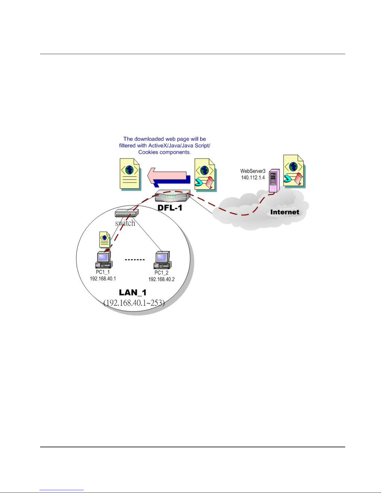
Content Filtering – Web Filters DFL-1500 User Manual
85
Chapter 13
Content Filtering – Web Filters
This chapter introduces web content filters and explains how to implement it.
13.1 Demands
Figure 13-1 Use web filter functionality to avoid users browsing the forbidden web site
1. As the above Figure 13-1 illustrates, so meone (PC1_1) is br owsing the web pages at the WebServer3. The contents of the
web pages may include cookies, Java applets, Java scripts or ActiveX objects that may contain malicious program of users’
information. So, we wish to prohibit the user (PC1_1) from downloading the forbidden components.
Page 92
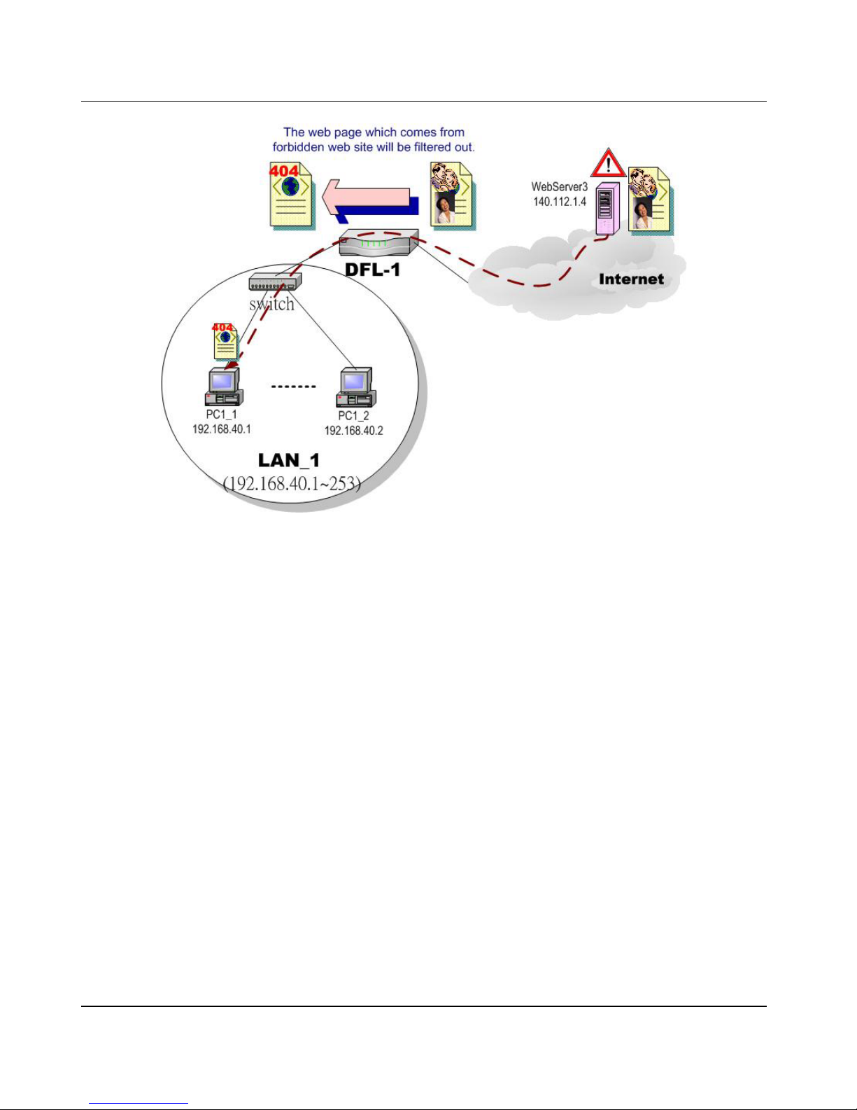
D-Link Part IV
86
Figure 13-2 Use we b filter functionality to avoid users v iew the forbidden web site
2. As the above Figure 13-2 illustrates, someone (PC1_1) is browsing forbidde n web pages on office hours. The contents of
the web pages may include stock markets, violence, or sex that will waste the bandwidth of the Internet access link while
degrading the efficiency of normal working hours. So, we wish to prohibit the user (PC1_1) fr om viewing the page on the
forbidden web site.
13.2 Objectives
1. Remove the cookies, Java applet, Java scripts, ActiveX objects from the web pages.
2. Prevent users from connecting to the forbidden sites.
13.3 Methods
1. Setup content filtering for web objects such as cookies and Java applets.
2. Setup content filtering for URL requests. For each URL, check the pre-defined upgradeable URL database, self-entered
forbidden domains, and self-entered keywords to check if the URL is allowed.
Page 93
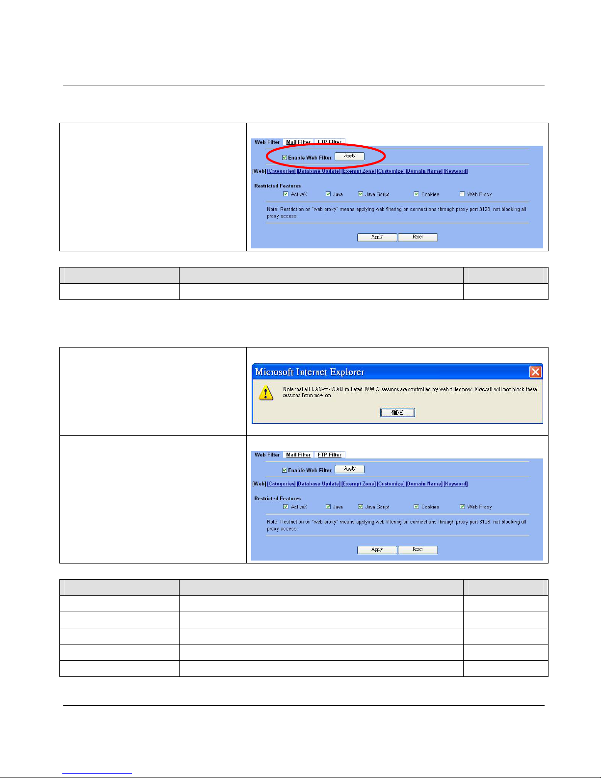
Content Filtering – Web Filters DFL-1500 User Manual
87
13.4 Steps
Step 1 - Enable Web Filter
Check the Enable Web Filter checkbox and
click the Apply right on the right side.
ADVANCED SETTI NGS > Content Filte r s > W e b Fil ter
FIELD DESCRIPTION EXAMPLE
Enable Web Filter Enable Web Filter feature of DFL-1500 enabled
Table 13-1 Enable Web Filter
Step 2 - Warning o f Firewall
This is a warning sayi ng that if you block any web
traffic from LAN-to-WAN in Firewall, the access
control is shift to the Web Filter. Namely, if you
block someone to access the web at the WAN
side, after enabling the web filter, he can resume
accessing the web until you set a content filter
rule to block it.
ADVANCED SETTI NGS > Content Filte r s > W e b Fil ter
Step 3 - Customize Objects
Check the objects of Restricted Features to
block the objects. Click the Apply button at the
bottom of this page.
Use PC1_1 to browse the
web page to see if the objects are blocked. If the
objects still exist, the objects ma y be cached by
the browser. Please clear the cache in the web
browser, close the browser, reopen the browser,
and connect to the web page again.
ADVANCED SETTI NGS > Content Filte r s > W e b Fil ter
FIELD DESCRIPTION EXAMPLE
Restricted Features Select the below items that will verified by Web Filter of DFL-1500.
ActiveX filter the web page that includes Activ eX enabled
Java filter the web page that includes Java enabled
Java Script filter the web page that includes Java Script enabled
Cookies filter the web page that includes Cookies enabled
Page 94
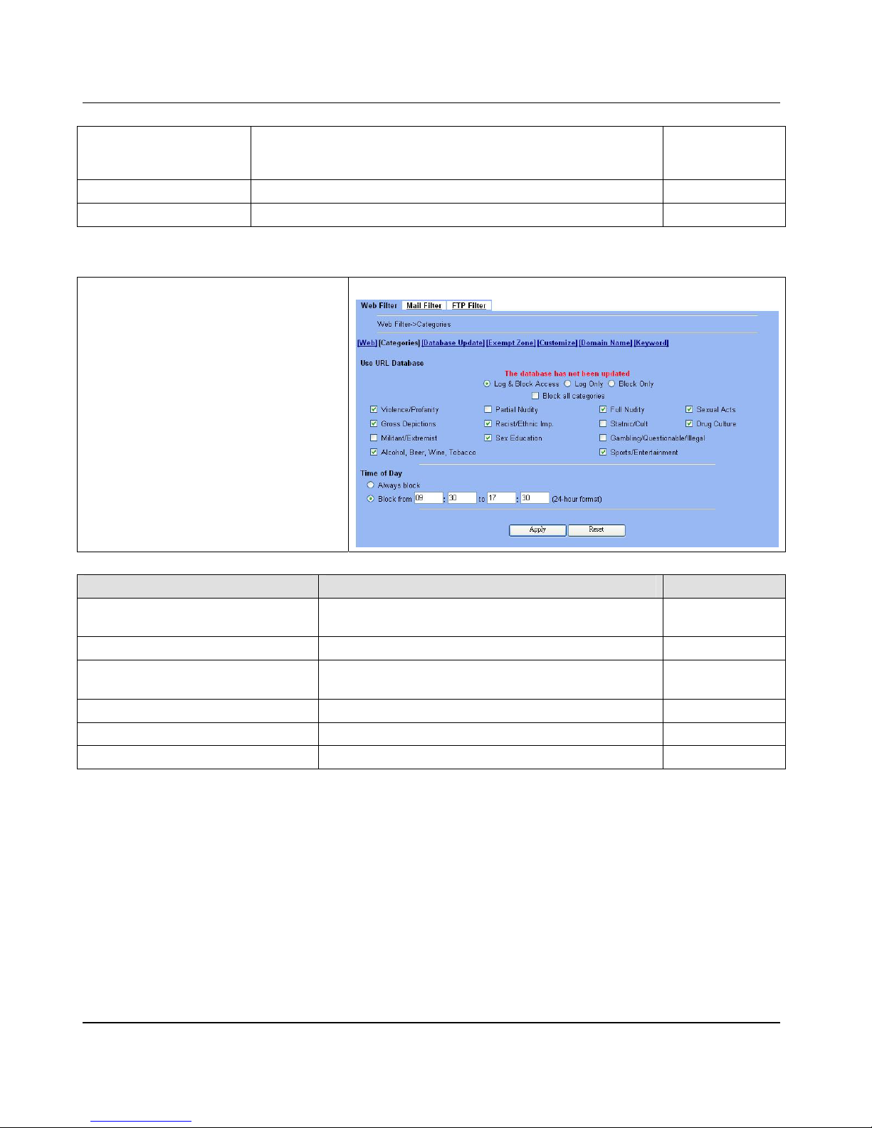
D-Link Part IV
88
Web Proxy
If enabling the “Web Proxy”, all the web pag es pass through proxy (Only
port 3128) will also be verified by DFL -1500. If disabling the “Web
Proxy”, all the web p a ges through will bypass the verificati on.
enabled
Apply Apply the settings which have been configured. N/A
Reset Clean the filled data and restore the original. N/A
Table 13-2 Web Filter setting page
Step 4 - Customize Categories
With the built-in URL database, DFL-1500 can
block web sessions towards several pre-defined
Categories of URLs. Check the items that you
want to block or log. Simply click the Block all
categories will apply all categories. Click Log
& Block Access if you want to block and log any
matched traffic. You can customize the Time of
Day to allow such traffic after the office hours,
such as 9:30 to 17:30.
ADVANCED SETTIN G S > Co nt ent Filters > W eb Filter > Categories
FIELD DESCRIPTION EXAMPLE
Use URL Database
Determine how to deal with the URL types in this page (Log
& Block Access, Log Only, Block Only)
Log & Block
Access
Block all categories Make all categories below enabled disabled
Violence/Profanity, Gross Depictions,
Militant/Extremist ,etc. items
Check the categories you would like to enable
Enable the checked
ones
Time of Day The time which was set for Web Filter. 09:30 ~ 17:30
Apply Apply the setting s which have been conf igured. N/A
Reset Clean the filled data and restore the original one. N/A
Table 13-3 Web Filter Categories setting page
Page 95
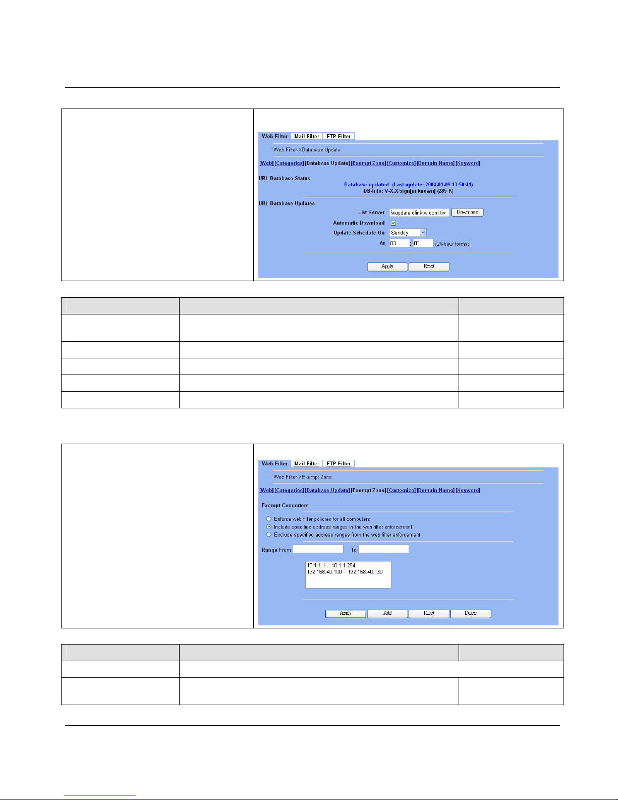
Content Filtering – Web Filters DFL-1500 User Manual
89
Step 5 - Update the Built-in Database
Click the Download button to ask DFL-1500 to
instantly download the database from the
fwupdate.dlinktw.com.tw. The DFL-1500
can be set to automatically check the site for any
new updates by checking the Automatic
Download. You can also configure how
frequently the DFL-1500 checks for the updates.
Click Apply to store the changes. From now on,
any traffic match ed wi th the U RLs i n t he dat a base
will be blocked by the DFL-1500.
ADVANCED SETTINGS > Content Filters > Web Filter > Database
Update
FIELD DESCRIPTION EXAMPLE
List Server
Determine the URL database website to download from (default is
fwupdate.dlinktw.com.tw).
fwupdate.dlinktw.com.tw
Automatic Download download the URL database automatically or not enabled
Update Schedule On Setup the automatically download time (DayOfWeek). Sunday At 03:00
Apply Apply the settings which have been configured. N/A
Reset Clean the filled data and restore the original one. N/A
Table 13-4 Web Filter database update
Step 6 - Further Customize the local
zones
You can configure to what range the filters will
apply to the l ocal zones. By defaul t, t he web fi lt ers
apply to all computers so the “Enforce web
filter policies for all computers” is
selected, and the range is 0.0.0.0 –
255.255.255.255. Delete the default r ange by
clicking the range item and the Delete button.
Enter the IP ra nge in the Range fields followed by
a click of the Add button to add one address
range to the web filter. Click “Include
…… “ and
Apply if you want web filters to only apply to the
specified ranges. Click “Ex
clude……“ and Apply
if you want web filters to apply to all computers
except those speci fied ranges.
ADVANCED SETTINGS > Content Filters > Web Filter > Exempt Zone
FIELD DESCRIPTION EXAMPLE
Exempt Computers Determine which IP range will exempt the verification by the web filter
Enforce web filter policies
for all computers
Web filter actives at all the computers, not limit range of the IP
addresses
disabled
Page 96
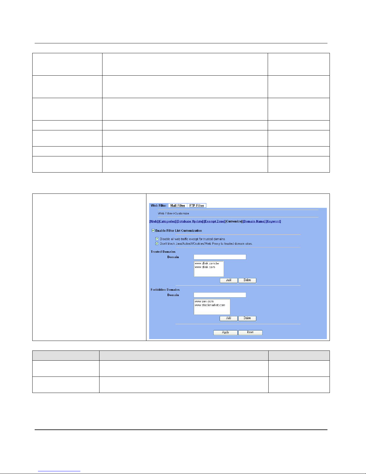
D-Link Part IV
90
Include specified address
ranges in the web filter
enforcement
Web filter will only active at below specified computers. enabled
Exclude specified addre s s
ranges from the web filter
enforcement
Except below specified IP address ranges. All the other IP address
range, Web filte r will a ctive totally.
disabled
Range From
Here we can setup the IP address range, for the above Exempt
Computers to use.
10.1.1.1 – 10.1.1.254
192.168.40.100 –
192.168.40.130
Apply A pply the above select ed “Exempt Computers” radius button. N/A
Add
Add the specified IP range which filled in the above “Range From”
field.
N/A
Reset Clean the filled data and restore the original one. N/A
Delete
Delete the specified IP range which filled in the above “Range From”
field.
N/A
Table 13-5 Web Filter Exempt Zone setting page
Step 7 - Further Customize the remote
sites
Check the Enable Filter List
Customization to allow all accesses to the
Trusted Domains while disallowing all
accesses to the Forbidden Domains. Check
the Disable all traffic except for
trusted domains if you want to only al low the
access to the Trusted Domains. However, if the
web objects are set to be blocked by the
DFL-1500 in step 3, thes e allowed ac cesses will
never be able to retri eve th es e object s. Ch e ck the
“Don’t block …” to allow the objects for these
trusted domains. The domains are maintained by
enter the address in the Domain field with a click
of the Add button. To delete a domain, click the
domain with a click of the Delete button.
ADVANCED SETTIN G S > Content Filt ers > Web Filter > Customize
FIELD DESCRIPTION EXAMPLE
Enable Filter List
Customization
Enable the Filter List Customization feature of web filter Enabled
Disable all web traffic
except for trusted domains
Except the following specified domain range specified by the trusted
domain. All the other URL domain IP addresses are all blocked access.
Enabled
Page 97
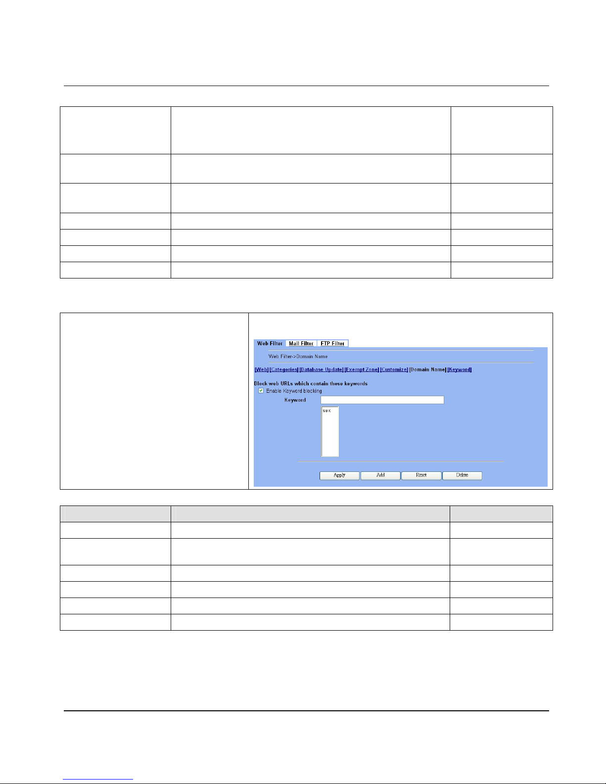
Content Filtering – Web Filters DFL-1500 User Manual
91
Don't block
Java/ActiveX/Cookies/Web
Proxy to trusted domain
sites
In the follo wing d omai n ran ge of th e truste d dom ains. If ther e ar e incl ude
Java/ActiveX/Cookies/Web Proxy components in the web page, the
action is setting not to block.
Enabled
Trusted Domains
Domain
Here we can specify the Trusted Domains for the above item using.
www.dlink.com.tw
www.dlink.com
Forbidden Domains
Domain
Here we can specify the Forbidden Domains for the above item using.
www.sex.com
www.stockmarket.com
Add Add the Trusted/Forbidden Domains IP range to the list. N/A
Delete Delete the Trusted/Forbidden Domains IP range from the list. N/A
Apply Apply the setting which configured on the checkbox. N/A
Reset Clean the filled data and restore the original one. N/A
Table 13-6 Web Filter Customize setting page
Step 8 - Setup URL keyword bloc king
Check the Enable Keyword Blocking to block
any URLs that contains the entered keywords.
Add a key word by entering a word in the
keyword field followed by a click of Add.
ADVANCED SETTINGS > Content Filters > Web Filter > Domain
Name
FIELD DESCRIPTION EXAMPLE
Enable Keyword blocking Enable URL keywor d blocking feature of web filter Enabled
Keyword
If the Keyword appears in the URL when connect to the Internet using
browser. The contents about the URL will be block.
sex
Apply Apply the setting which configured on the checkbox. N/A
Add Add the Keyword to the list. N/A
Reset Clean the filled data and restore the original one. N/A
Delete Delete the selected keyword from the list. N/A
Table 13-7 Web Filter Domain Name set ting page
Page 98
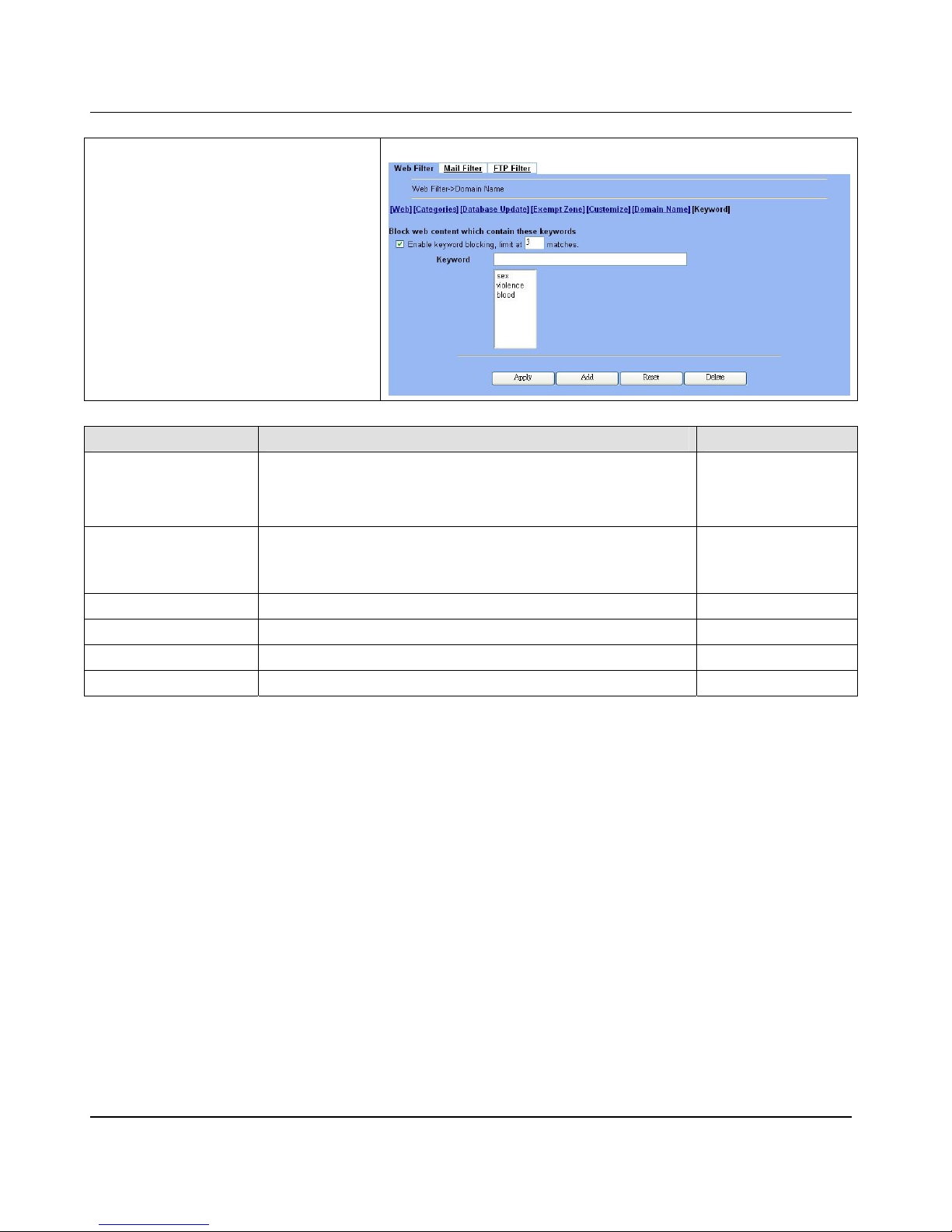
D-Link Part IV
92
Step 9 - Setup contents keywor d
blocking
Check the Enable Keyword Blocking to block
any Web pages that contain the entered
keywords. Add a key word by entering a word in
the Keyword field and then click Add to proceed.
Note that you can add the keywords as many as
you like.
ADVANCED SETTIN G S > Content Filt ers > Web Filter > Keyword
FIELD DESCRIPTION EXAMPLE
Enable keyword blocking,
limit at __ matches
Check Enable keyword blocking, and then the web pages will be blocked
if the keywords below you have added are ap peared in the pages. "Limit
at 3 matches" means that the webpages will be blocked as long as any of
the added keywords appear equal or more than three times.
Enabled
3 matches
Keyword Specify the keyword that you want to block.
sex
violence
blood
Apply Apply the settings which have been conf igured. N/A
Add Add the Keyword to the list. N/A
Reset Clean the filled data and restore the original one. N/A
Delete Delete the Keyword from the list. N/A
Table 13-8 Web Filter Content Keywords setting page
Page 99
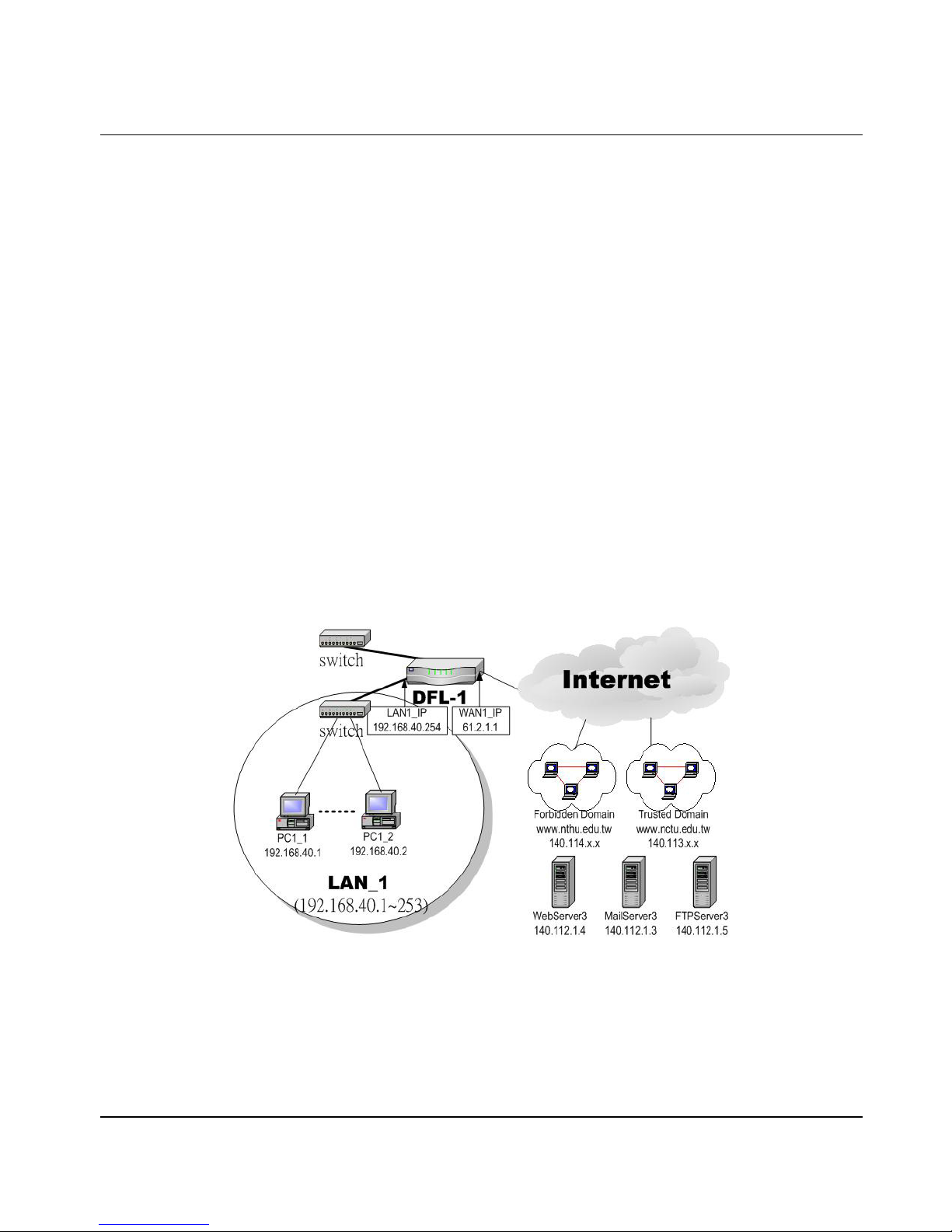
Content Filtering – Mail Filters DFL-1500 User Manual
93
Chapter 14
Content Filtering – Mail Filters
This chapter introduces SMTP proxies and explains how to implement it.
14.1 Demands
Sometimes there are malicious scripts like *.vbs that may be attached in the email. If the users accidentally open such files, their
computers may be infectious with virus.
14.2 Objectives
Modify the filename extension of the suspicious email attachments so that email receivers may notice that the file cannot be
directly opened by the operating system because of the unrecognized filename extension.
14.3 Methods
1. Setup SMTP filters for outgoing emails from PC_1 (in LAN1) towards the mail server (in DMZ1 or in WAN1) to append a
“.bin” to all vbs attachments. Use PC1_ 1 to send an email with vbs attachments to test the configuration.
2. Setup POP3 filters for incoming emails from a mail server (in WAN1 or in DMZ1) to PC_1 (in LAN1) to append a “.bin”
to all vbs attachments. Use PC1_1 to retrieve an email with vbs attachments to test the configuration.
Figure 14-1 Use SMTP / POP3 filter functionality to avoid some sensitive e-mail dir ectly opened
Page 100
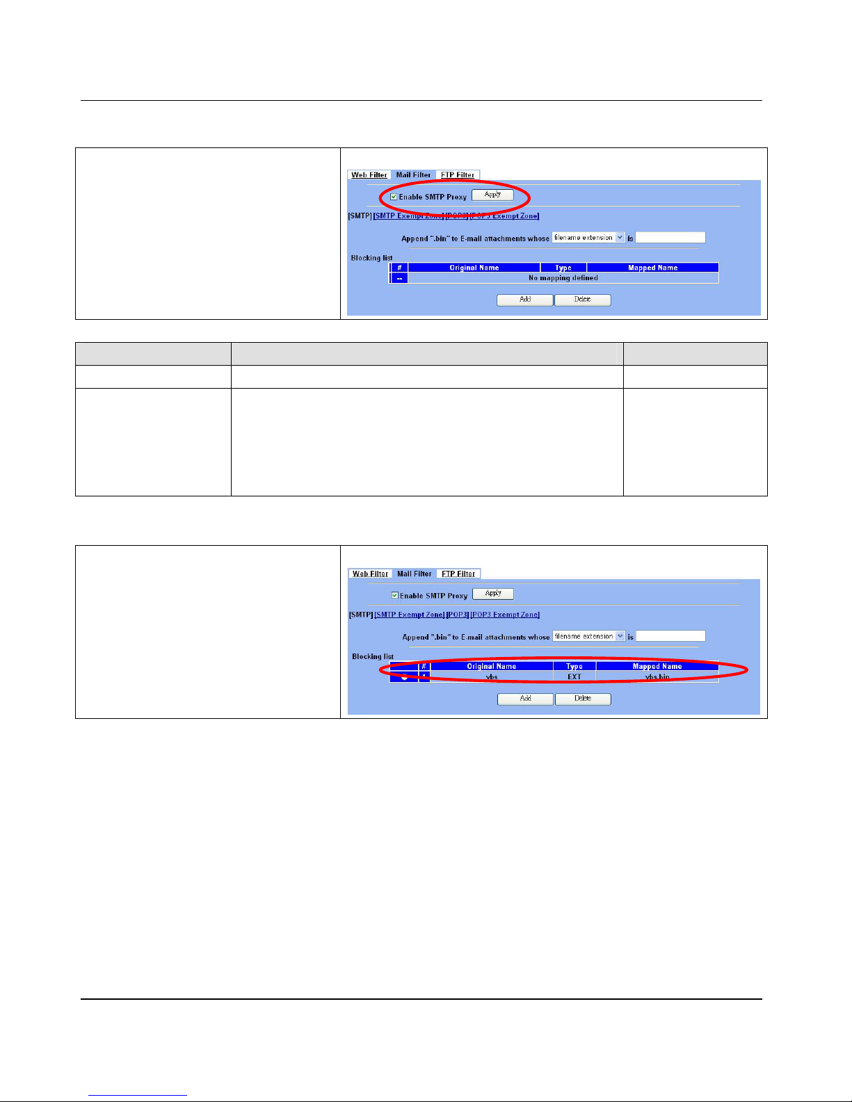
D-Link Part IV
94
14.4 Steps for SMTP Filters
Step 1 – Enable SMTP Filters
Check the Enable SMTP Proxy checkbox and
click Apply.
ADVANCED SETTINGS > Content Filters > Mail Filters > SMTP
FIELD DESCRIPTION EXAMPLE
Enable SMTP Proxy Enable SMTP Proxy feature of DFL-1500 enabled
Append ".bin" to E-mail
attachments whose
¾ Filename extension
When the filename extensio n of attac hme nt file matc hes “Fi lename
extension”, add the “.bin” extension to the attachment file.
¾ Exact filename
When the whole filename of attachment file matches “Exact filename”,
add the “.bin” extension to the attachment file.
Filename extension
Table 14-1 Mail F ilter SMTP setting page
Step 2 – Add a SMTP Filter
Select filename extension, enter vbs, and
click Add to add a rule. This rule will apply to all
LAN-to-DMZ/WAN SMTP connections. All such
SMTP traffic will be examined to change the
filename extension from vbs to vbs.bin.
ADVANCED SETTINGS > Content Filters > Mail Filters > SMTP
 Loading...