

Page 1
DFL-1000
Workgroup Firewall
’
User
s Manual
Rev. 02 (March, 2002)
D-Link Systems, Inc.
DFL-1000 User’s Manual
1
Page 2

© Copyright 2002 D-Link Systems, Inc. All rights reserved.
No part of this publication including text, examples, diagrams or illustrations may be reproduced,
transmitted, or translated in any form or by any means, electronic, mechanical, manual, optical or
otherwise, for any purpose, without prior written permission of D-Link Systems, Inc.
DFL-1000 User’s Manual
Version 2.2
28 Mach 2002
Trademarks
Products mentioned in this document are trademarks or registered trademarks of their respective holders.
Regulatory Compliance
FCC Class A Part 15 CSA/CUS
DFL-1000 User’s Manual
2
Page 3

Table of Contents
Introducing the DFL-1000..........................................................................9
Firewall......................................................................................................................................................9
Network Address Translation (NAT)................................................................................................... 10
Transparent mode ..............................................................................................................................10
Hacker prevention and protection........................................................................................................... 10
VPN.........................................................................................................................................................11
Virus and worm protection......................................................................................................................11
Web content filtering ............................................................................................................................... 11
Secure installation, configuration, and management .............................................................................12
Web-based manager ..........................................................................................................................12
Command line interface......................................................................................................................13
Logging and reporting.........................................................................................................................13
About this document ...............................................................................................................................13
Customer service and technical support ................................................................................................ 14
Installing the DFL-1000............................................................................15
Before you start ......................................................................................................................................15
NAT mode install ................................................................................................................................15
Transparent Mode Install.................................................................................................................... 16
Unpacking the DFL-1000........................................................................................................................ 17
Mounting the DFL-1000..........................................................................................................................17
Powering on the DFL-1000..................................................................................................................... 18
Using the Quick Setup Wizard................................................................................................................ 18
Connecting to the web-based manager .............................................................................................18
Starting the Quick Setup Wizard ........................................................................................................19
Reconnecting to the web-based manager.......................................................................................... 19
Configuring the DFL-1000 from the CLI .................................................................................................19
Connecting to the CLI.........................................................................................................................20
Configuring the DFL-1000 to run in NAT mode.................................................................................. 20
Configuring the DFL-1000 to run in Transparent mode .....................................................................21
Connecting the DFL-1000 to your network............................................................................................. 22
NAT mode connections ...................................................................................................................... 22
Transparent mode connections..........................................................................................................23
Configuring your internal network...........................................................................................................24
Completing the configuration..................................................................................................................24
Configuring the DMZ interface ...........................................................................................................24
Setting the date and time....................................................................................................................25
Firewall Configuration ............................................................................ 26
Controlling connections from the Internet...............................................................................................26
Accepting incoming connections in NAT mode .................................................................................. 26
DFL-1000 User’s Manual
3
Page 4

Accepting incoming connections in Transparent mode...................................................................... 27
Denying incoming connections........................................................................................................... 28
Arranging policies in the incoming policy list ...................................................................................... 29
Controlling connections to the Internet ................................................................................................... 29
Denying connections to the Internet from the internal network .......................................................... 30
Accepting connections to the Internet from the internal network .......................................................31
Requiring authentication to connect to the Internet............................................................................ 32
Arranging policies in the Int to Ext and Outgoing policy list ...............................................................32
Controlling connections to and from the DMZ ........................................................................................ 33
Policies....................................................................................................................................................33
Policy information ...............................................................................................................................33
Default policy ...................................................................................................................................... 34
Adding policies ...................................................................................................................................34
Editing policies.................................................................................................................................... 35
Policy matching ..................................................................................................................................35
Arranging policies in the policy list .....................................................................................................35
Addresses...............................................................................................................................................35
Adding addresses...............................................................................................................................36
Editing addresses ............................................................................................................................... 36
Organizing addresses into address groups........................................................................................37
Services .................................................................................................................................................. 37
Pre-defined services...........................................................................................................................38
Providing access to custom services ................................................................................................. 39
Grouping services............................................................................................................................... 39
Schedules ............................................................................................................................................... 40
Creating one-time schedules.............................................................................................................. 40
Creating recurring schedules..............................................................................................................41
Applying a schedule to a policy .......................................................................................................... 42
Users and authentication........................................................................................................................42
Adding authentication to a policy........................................................................................................ 43
Virtual IPs ...............................................................................................................................................44
Adding Virtual IPs ............................................................................................................................... 44
IP/MAC binding.......................................................................................................................................44
Adding IP/MAC binding addresses..................................................................................................... 45
Enabling IP/MAC binding....................................................................................................................45
Traffic shaping ........................................................................................................................................45
Adding traffic shaping to a policy........................................................................................................ 45
VPN pass through...................................................................................................................................46
Adding IPSec and PPTP pass through ..............................................................................................46
IPSec VPNs............................................................................................... 47
Compatibility with third-party VPN products ...........................................................................................47
Autokey IPSec VPN between two networks...........................................................................................47
Creating the VPN tunnel..................................................................................................................... 48
DFL-1000 User’s Manual
4
Page 5

Adding internal and external addresses ............................................................................................. 49
Adding an IPSec VPN policy .............................................................................................................. 50
Autokey IPSec VPN for remote clients ................................................................................................... 51
Configuring the VPN tunnel for the client VPN...................................................................................52
Adding internal and external addresses ............................................................................................. 53
Adding an IPSec VPN policy .............................................................................................................. 53
Configuring the VPN client ................................................................................................................. 54
Manual key exchange IPSec VPN between two networks..................................................................... 54
Configuring the VPN tunnel................................................................................................................55
Adding internal and external addresses ............................................................................................. 55
Adding an IPSec VPN policy .............................................................................................................. 56
Manual key exchange IPSec VPN for remote clients.............................................................................56
Configuring the VPN tunnel................................................................................................................56
Adding internal and external addresses ............................................................................................. 56
Adding an IPSec VPN policy .............................................................................................................. 56
Testing a VPN......................................................................................................................................... 57
PPTP and L2TP VPNs .............................................................................. 58
PPTP VPN configuration ........................................................................................................................58
Configuring the DFL-1000 as a PPTP server..................................................................................... 59
Configuring a Windows 98 client for PPTP ........................................................................................60
Configuring a Windows 2000 Client for PPTP.................................................................................... 61
Configuring a Windows XP Client to connect to a DFL-1000 PPTP VPN.......................................... 61
L2TP VPN configuration ......................................................................................................................... 62
Configuring the DFL-1000 as an L2TP server....................................................................................63
Configuring a Windows 2000 Client for L2TP ....................................................................................64
Configuring a Windows XP Client to connect to a DFL-1000 L2TP VPN .......................................... 65
RADIUS authentication for PPTP and L2TP VPNs ................................................................................ 66
Adding RADIUS server addresses ..................................................................................................... 67
Turning on RADIUS authentication for PPTP.....................................................................................67
Turning on RADIUS authentication for L2TP .....................................................................................67
Intrusion detection system (IDS) ............................................................ 68
Attack prevention .................................................................................................................................... 68
Alert email...............................................................................................................................................68
Configuring alert email........................................................................................................................ 68
Testing email alerts ............................................................................................................................69
Virus protection........................................................................................70
Virus and worm protection for your internal network .............................................................................. 70
Configuring high level virus protection for your internal network........................................................ 71
Configuring medium level virus protection for your internal network ................................................. 72
Configuring low level virus protection for your internal network ......................................................... 73
Configuring worm protection for your internal network....................................................................... 74
Virus and worm protection for incoming connections.............................................................................74
DFL-1000 User’s Manual
5
Page 6

High level virus protection for incoming connections ......................................................................... 74
Medium level virus protection for incoming connections....................................................................75
Low level virus protection for incoming connections .......................................................................... 76
Worm protection for incoming connections ........................................................................................76
Updating your antivirus database ........................................................................................................... 77
Updating the antivirus database manually .........................................................................................77
Configuring automatic antivirus database updates ............................................................................ 77
Displaying virus and worm lists ..............................................................................................................78
Web content filtering ...............................................................................79
Blocking web pages that contain undesired words ................................................................................79
Enabling the banned word list ............................................................................................................79
Adding words to the banned word list ................................................................................................79
Temporarily disabling the banned word list........................................................................................80
Temporarily disabling individual words in the banned word list .........................................................80
Clearing the banned word list.............................................................................................................80
Creating the banned word list using a text editor ...............................................................................80
Blocking access to Internet sites ............................................................................................................81
Enabling the URL block list.................................................................................................................81
Adding URLs to the URL block list .....................................................................................................81
Temporarily disabling the URL block list ............................................................................................81
Temporarily disabling blocking individual URLs.................................................................................81
Clearing the URL block list ................................................................................................................. 82
Creating the URL block list using a text editor ...................................................................................82
Removing scripts from web pages .........................................................................................................82
Logging and reporting.............................................................................84
Configuring logging................................................................................................................................. 84
Recording logs on a remote computer ...............................................................................................84
Selecting what to log ..........................................................................................................................85
Log message formats ............................................................................................................................. 85
Traffic log message format.................................................................................................................86
Event log message format.................................................................................................................. 86
Attack log message format.................................................................................................................87
Viewing and maintaining logs ................................................................................................................. 88
Viewing logs .......................................................................................................................................88
Searching logs....................................................................................................................................89
Downloading a log file to the management computer ........................................................................ 89
Deleting all of the messages in an active log .....................................................................................90
Deleting a saved log file ..................................................................................................................... 90
Administering the DFL-1000 ...................................................................91
Logging into the web-based manager .................................................................................................... 91
System status .........................................................................................................................................91
Changing the operating mode ............................................................................................................ 92
DFL-1000 User’s Manual
6
Page 7

Upgrading the DFL-1000 firmware ..................................................................................................... 92
Updating your antivirus database.......................................................................................................92
Displaying the DFL-1000 serial number ............................................................................................. 92
Restoring system settings ..................................................................................................................93
Restoring system settings to factory defaults.....................................................................................93
Restarting the DFL-1000 .................................................................................................................... 95
Shutting down the DFL-1000.............................................................................................................. 95
System status monitor ........................................................................................................................ 95
Network configuration.............................................................................................................................96
Changing IP addresses ...................................................................................................................... 96
Configuring the external interface for DHCP......................................................................................96
Configuring the external interface for PPPoE.....................................................................................96
Changing MTU size to improve network performance ....................................................................... 97
Setting DNS server addresses ........................................................................................................... 97
Controlling management access to the DFL-1000.............................................................................97
Configuring routing .............................................................................................................................98
Enabling RIP server support...............................................................................................................98
Providing DHCP services to your internal network ............................................................................ 99
System configuration ............................................................................................................................100
Setting system date and time ........................................................................................................... 100
Changing web-based manager options............................................................................................ 101
Adding and editing administrator accounts ......................................................................................101
Configuring SNMP............................................................................................................................102
Using the DFL-1000 CLI.........................................................................104
Connecting to the DFL-1000 CLI..........................................................................................................104
Connecting to the DFL-1000 communications port..........................................................................104
Connecting to the DFL-1000 CLI using SSH.................................................................................... 105
CLI basics ............................................................................................................................................. 105
Recalling commands ........................................................................................................................105
Editing commands ............................................................................................................................ 105
Using command shortcuts................................................................................................................106
Using command help........................................................................................................................ 106
Installing firmware from a TFTP server ................................................................................................106
Glossary.................................................................................................. 109
Troubleshooting FAQs .......................................................................... 112
General administration..........................................................................................................................112
Network configuration...........................................................................................................................112
Firewall policies ....................................................................................................................................112
Schedules ............................................................................................................................................. 113
VPN.......................................................................................................................................................113
Virus protection.....................................................................................................................................114
Web content filtering ............................................................................................................................. 114
DFL-1000 User’s Manual
7
Page 8

Logging ................................................................................................................................................. 114
Technical Support..................................................................................116
DFL-1000 User’s Manual
8
Page 9
Introducing the DFL-1000
The DFL-1000 is one of a series of new generation all-layer security products that provide comprehensive
protection for your internal network. These products, Application Security Gateways, combine key security
technologies into a dedicated platform designed for high performance and reliability. In a compact, easy
to install and configure package the DFL-1000 combines:
• A fully-configurable firewall
• Hacker attack prevention and protection
• Virtual private networking (VPN)
• Virus protection
• Content filtering
• Easy and secure configuration management
Employing high-performance architecture, a dedicated co-processor, proprietary BIOS and OS firmware,
the DFL-1000 offers the best and highest performance solution for securing your business network.
Firewall
The core function of the DFL-1000 is a state-of-the-art firewall that protects computer networks from the
hostile environment of the Internet. The firewall provides control of security policies through a carefully
designed interface that is easy to use but allows full control even in complex situations.
DFL-1000 security policies include a complete range of options that:
• Control incoming and outgoing traffic
• Block or allow access for all policy options
• Control when individual policies are in effect
• Accept or deny traffic to and from individual addresses
• Control standard and user definable network services individually or in groups
• Require users to enter passwords before gaining access to the Internet
• Include traffic shaping to set priority and guarantee or limit bandwidth for each policy
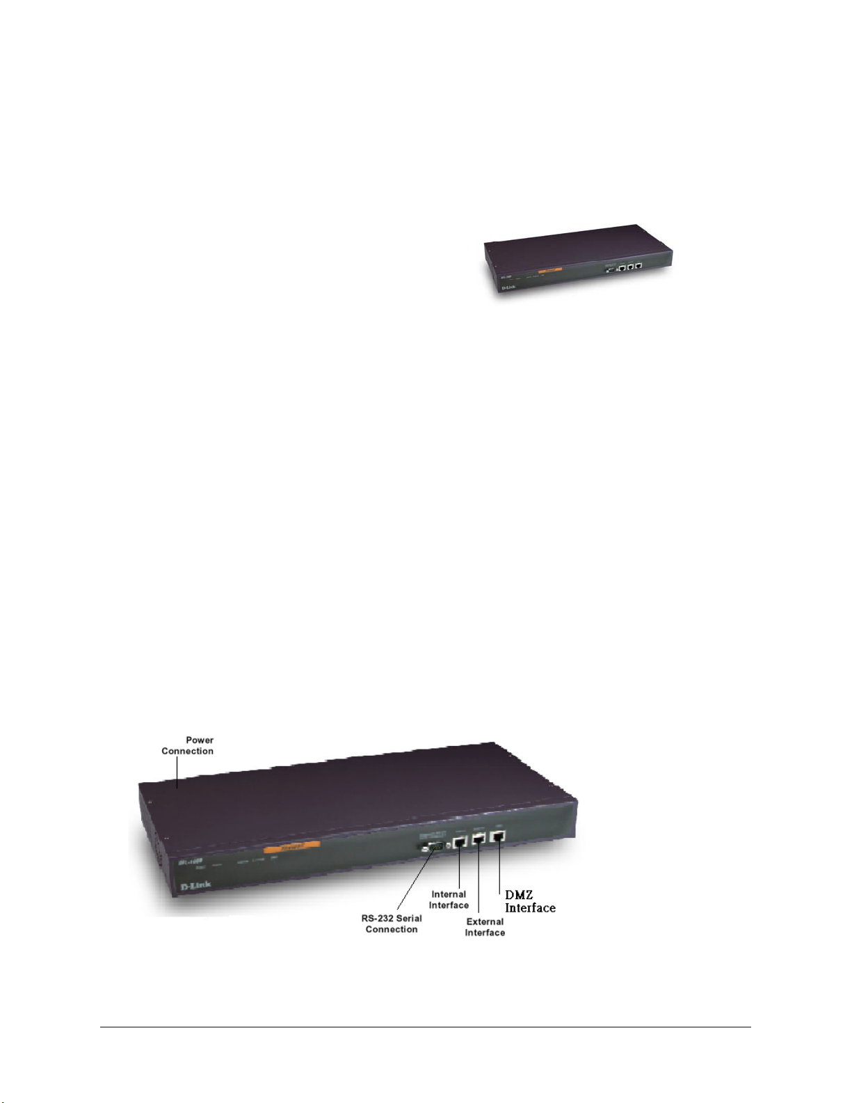
• Front view of the DFL-1000:
DFL-1000 User’s Manual
9
Page 10

Network Address Translation (NAT)
In NAT mode, the DFL-1000 is installed as a privacy barrier between the internal network and the Internet.
The firewall provides network address translation to protect the private network. In NAT mode, you can
add a DMZ network to provide public access to Internal servers while protecting them behind the firewall
on a separate internal network.
Features supported in NAT mode include:
• Firewall protection, allow/deny traffic according to source/destination address, service, and time of
day
• VPN, virus protection, and Web content filtering
• IP/MAC binding
• DHCP configuration of the DFL-1000 external network address
• Detailed logging
Transparent mode
Transparent Mode provides even quicker and easier installation when the requirement is to provide
firewall protection to a pre-existing network with public addresses. The internal and external network
interfaces of the DFL-1000 can be in the same network; therefore, the DFL-1000 can be inserted into
your network at any point without the need to make any changes to your network.
Packets arriving at the DFL-1000 are intelligently forwarded to the correct network interface and firewall
policies prevent unauthorized access to your network.
Transparent mode provides the same basic firewall protection as NAT mode. However, more advanced
features such as the DMZ network, VPN, virus scanning, and content filtering are only available in NAT
mode.
Hacker prevention and protection
The DFL-1000 is built to defend your network from network attacks including:
• Distributed Denial-Of-Service (DDOS) attacks
SYN Attack
ICMP Flood
UDP Flood
• IP fragmentation attacks
Ping of Death Attack
Tear Drop Attack
Land Attack
• Port Scan Attack
• IP Source Routing
• IP Spoofing Attack
• Address Sweep Attack
• WinNuke Attack
You can configure email alerts that send an email to the system administrator when the DFL-1000 detects
one of these attacks. You can also configure email alerts to provide real time warnings of ongoing attacks.
Up to three email recipients can be specified.
DFL-1000 User’s Manual
10
Page 11

VPN
Using the DFL-1000 integrated VPN, you can provide a secure connection between widely separated
office networks or securely link telecommuters or travellers to your office network. The DFL-1000 industry
standard VPN creates an encrypted traffic tunnel between DFL-1000-protected networks or between a
DFL-1000 and third-party VPN products that support IPSec. VPN features include:
• IPSec, ESP security in tunnel mode
• Hardware accelerated encryption using IPSEC, DES, and 3DES (triple-DES)
• HMAC MD5 or HMAC SHA authentication and data integrity
• Automatic IKE (Internet Key Exchange) and manual key exchange
• PPTP for easy connectivity with the VPN standard supported by the most popular operating systems
• L2TP for easy connectivity with a more secure VPN standard also supported by many popular
operating systems
Virus and worm protection
D-Link's DFL-1000 secure gateway solution adds anti-virus and anti-worm functionality to conventional
VPN and firewall. Virus and worm protection screens the information found in web (HTTP protocol) and
email content (SMTP, POP3, and IMAP protocols) for the following types of target files:
• Executable files (exe, bat, and com)
• Visual basic files (vbs)
• Compressed files (zip, gzip, tar, hta, and rar)
• Screen saver files (scr)
• Dynamic link libraries (dll)
• MS Office files
You can configure DFL-1000 virus scanning to block the target files or scan them for viruses and worms.
You can configure three levels of virus protection:
• High level protection removes target files from HTTP transfers and email attachments before they
pass through the firewall
With high level protection turned on, the DFL-1000 does not perform virus scanning. Instead, all files
and attachments are identified and removed from content protocol data streams.
• Medium level protection scans all target files for viruses
You can configure the virus scanning engine to perform up to four different types of virus scans on
each target file.
• Low level protection temporarily suspends virus protection
All target files are forwarded unchanged to their destinations.
You can also configure worm scanning to look for filenames known to be used by worms. For example,
the Nimda worm uses files named readme.exe and sample.exe.
DFL-1000 content virus and worm prevention is transparent to the end user. Client and server programs
require no special configuration, and D-Link high-performance hardware and software ensure there are
no noticeable download delays.
Web content filtering
Using Web content filtering, you can screen for three types of web content:
DFL-1000 User’s Manual
11
Page 12

• Unwanted content such as adult sites
• Unwanted URLs such as stock quote/trading sites
• Unsecure web content such as:
Java Applets
Cookies
Malicious Scripts
ActiveX
Site blocking is accomplished by scanning URLs or web pages for user defined patterns.
Secure installation, configuration, and management
Installation is quick and simple. All that is required to get the DFL-1000 up and running and protecting
your network is to connect to the web-based manager and use the Quick Setup Wizard to configure the
DFL-1000. You can also perform the basic configuration from the DFL-1000 command line interface (CLI).
When initially connected to your network, the DFL-1000 comes with a default configuration that provides
basic security features. From this foundation you can use the web-based manager to customize the
configuration to meet your needs.
Web-based manager
Using a secure HTTPS connection from any computer running Internet Explorer, you can configure and
manage the DFL-1000. It can also be configured for secure administration from the external network
(Internet).
Configuration changes made with the web-based manager are effective immediately without the need to
reset the firewall or interrupt service.
Once a satisfactory configuration has been established, it can be downloaded and saved. The saved
configuration can be restored at any time.
DFL-1000 User’s Manual
12
Page 13
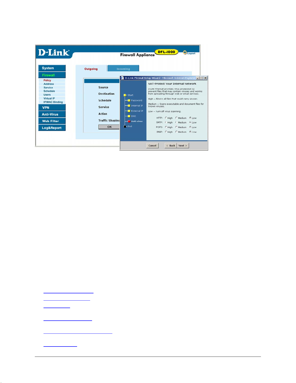
The DFL-1000 web-based manager and quick setup wizard:
Command line interface
For troubleshooting and professional scripting, a command line interface is available by connecting a
management computer to the DFL-1000 RS-232 serial connection.
Logging and reporting
The DFL-1000 supports logging of various categories of traffic and of configuration changes. You can
configure logging to:
• Report traffic that connects to the firewall interfaces
• Report network services used
• Report traffic permitted by firewall policies
• Report traffic that was denied by firewall policies
• Report configuration changes
Logs can be sent to a remote syslog server or saved on an optional hard drive installed in the DFL-1000.
About this document
This user manual describes how to install and configure the DFL-1000. This document contains the
following chapters:
• Installing the DFL-1000
• Firewall Configuration
• IPSec VPNs
between an internal network and a client
• PPTP and L2TP VPNs
a windows client
• Intrusion detection system (IDS)
common network attacks
• Virus protection
describes how to create an IPSec VPN between two internal protected networks and
describes how use the DFL-1000 to protect your network from viruses and worms
describes how to configure firewall policies to enhance firewall protection
describes how to configure PPTP and L2TP VPNs between the DFL-1000 and
describes how to configure the DFL-1000 to detect and prevent
DFL-1000 User’s Manual
13
Page 14

• Web content filtering describes how to configure Web content filters to prevent unwanted Web
content from passing through the DFL-1000
• Logging and reporting
DFL-1000
• Administering the DFL-1000
• Using the DFL-1000 CLI
using the CLI
• The Glossary
• Troubleshooting FAQs
defines many of the terms used in this document
describes how to configure logging and reporting to track activity through the
describes DFL-1000 management and administrative tasks
introduces the DFL-1000 CLI and describes the basics of connecting to and
help you find the information you need if you run into problems
Customer service and technical support
For updated product documentation, technical support information, and other resources, please visit our
web site at http://tsd.dlink.com.tw
You can contact D-Link Technical Support at your local D-Link office:
• See Technical Support
To make it possible for us to provide the support you require, please provide the following information:
• Name
• Company Name
• Location
• Email address
• Telephone Number
• Software Version
• Serial Number
• Detailed description of your problem
DFL-1000 User’s Manual
14
Page 15

Installing the DFL-1000
This chapter describes how to install the DFL-1000 firewall between your network and the Internet. After
you have completed the procedures in this chapter, your DFL-1000 will be up and running and protecting
your internal network.
This chapter includes:
• Before you start
• Unpacking the DFL-1000
• Mounting the DFL-1000
• Powering on the DFL-1000
• Using the Quick Setup Wizard
Configuring the DFL-1000 from the CLI
•
Connecting the DFL-1000 to your network
•
Configuring your internal network
•
Completing the configuration
•
Before you start
Before starting the installation of the DFL-1000, you must decide whether you are going to be running it in
NAT mode or Transparent mode. This choice determines the information that you require to install the
DFL-1000 as well as the installation steps that you perform.
NAT mode install
Use NAT mode configuration information to collect the information required to configure the DFL-1000 to
run in Network Address Translation (NAT) mode.
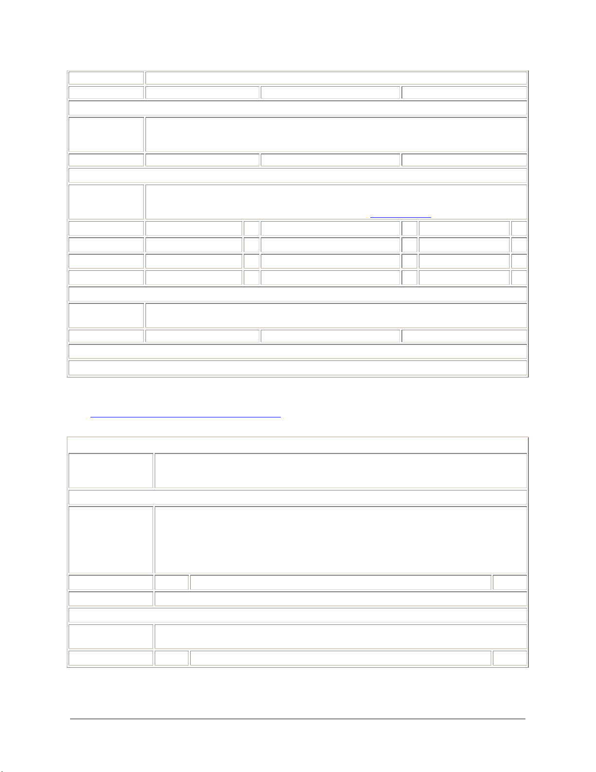
NAT mode configuration information (Part 1 of 2)
1. Administrator
Password
2. Internal
Interface
IP Netmask
3. External
Interface
IP Address* Netmask
Gateway
4. DNS Server
Specify an administrator password. The password should be difficult to guess. It must be at least
6 characters long and may contain numbers (0-9) and upper and lower case letters (A-Z, a-z), but
no spaces.
In the space below, record the IP address and netmask to connect the DFL-1000 to your internal
network.
If your ISP has assigned you a static IP address, put a check mark next to Manual below. Record
the Manual IP address and netmask to connect the DFL-1000 to the internet and record the IP
address of your default internet IP gateway.
If your ISP supplies you with an IP address using DHCP or PPPoE, check the appropriate box
below.
Manual DHCP
PPPoE
DFL-1000 User’s Manual
15
Page 16
by your ISP.
Primary Secondary
5. DHCP Server
(optional)
Starting IP Ending IP
6. Anti-Virus
(optional)
HTTP High
SMTP High
POP3 High
IMAP High
7. DMZ Interface
(Optional)
IP Netmask
* The Internal and External IP addresses must be on separate subnets.
If you plan to use the DFL-1000 as a DHCP server to assign IP addresses to the computers on
your internal network, you must specify the IP address range reserved to be assigned by the
DHCP server.
Choose virus protection levels to protect your internal network from viruses. You can set high,
medium, and low protection for web traffic (HTTP), and email traffic (SMTP, POP3, and IMAP).
For information on high, medium, and low protection, see Virus protection
Medium Low
Medium Low
Medium Low
Medium Low
In the space below, record the IP address and netmask to connect the DFL-1000 to your DMZ
network.
.
Transparent Mode Install
Use Transparent mode configuration information to collect the information required to configure the DFL1000 to run in Transparent mode.
Transparent mode configuration information
1. Administrator
Password
2. Transparent
Management IP
Management IP
Default Gateway
3. DNS Server
Primary
Specify an administrator password. The password should be difficult to guess. It must be at
least 6 characters long and may contain numbers (0-9) and upper and lower case letters (A-Z,
a-z), but no spaces.
In the space below, record the IP address and netmask to connect the DFL-1000 to a network
for management. Management can be done from a computer on your internal network or from
a separate network.
Also record the IP address of the default gateway required to connect the DFL-1000 to a
network for management. The default gateway address is not required if the management
computer can be reached without going through a default gateway.
In the space below, record the IP addresses of the primary and secondary DNS servers
provided by your ISP.
Netmask
Secondary
DFL-1000 User’s Manual
16
Page 17
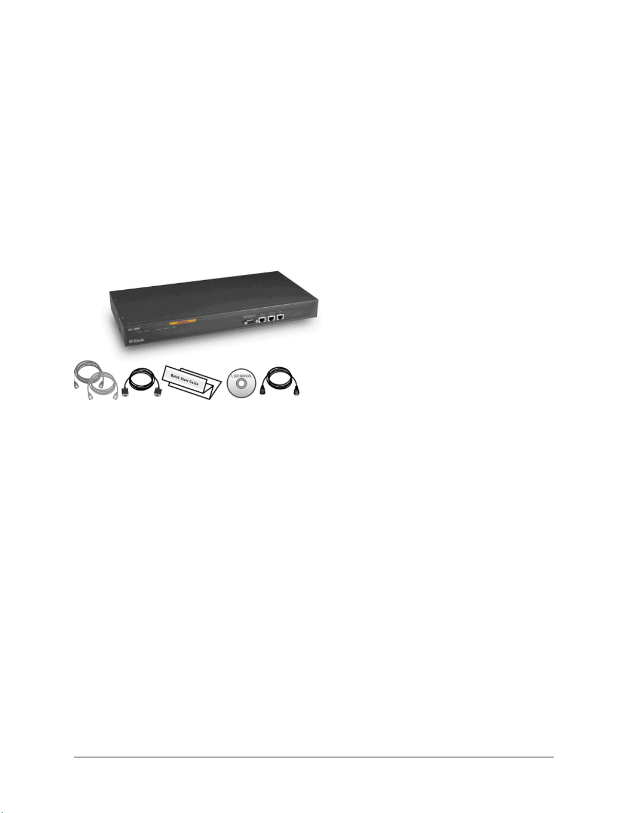
Unpacking the DFL-1000
The DFL-1000 package contains the following items:
• The DFL-1000 firewall
• A blue cross-over ethernet cable
• A gray regular ethernet cable
• A null-modem cable
• The DFL-1000 Quick Start Guide
• A CD containing this DFL-1000 User Manual
• A power cord
DFL-1000 package contents
Mounting the DFL-1000
The DFL-1000 can be mounted on a standard 19-inch rack. It requires 1 U of vertical space in the rack.
The DFL-1000 can be installed as a free-standing appliance on any stable surface. For free-standing
installation, make sure the appliance has at least 1.5 in. (3.75 cm) of clearance on each side to allow for
adequate air flow and cooling.
Dimensions
• 426 x 252 x 44 mm (Rack mount, 1 U height)
Weight
• 7.25 lb.
Power requirements
• Power Dissipation: 50 W (max)
• AC input voltage: 100 to 240 VAC
• AC input current: 1.6 A
• Frequency: 50 to 60 Hz
DFL-1000 User’s Manual
17
Page 18

Environmental specifications
• Operating Temperature: 32 to 104 °F (0 to 40 °C)
• Storage Temperature: -13 to 158 °F (-25 to 70 °C)
• Humidity: 5 to 95% non-condensing
Powering on the DFL-1000
To power on the DFL-1000:
• Make sure the power switch on the back of the DFL-1000 is turned off.
• Connect the power cord to the power connection at the back of the DFL-1000.
• Connect the power cord to a power outlet.
• Turn on the power switch.
The DFL-1000 starts up. The Power and Status lights light. The Status light flashes while the DFL-1000 is
starting up and remains lit when the system is up and running.
Using the Quick Setup Wizard
Use the procedures in this section to connect to the web-based manager and use the Quick Start Wizard
to create your initial DFL-1000 configuration.
Connecting to the web-based manager
To connect to the web-based manager you require:
• A computer with an ethernet connection
• Internet Explorer version 4.0 or higher
• A crossover cable or an ethernet hub and two ethernet cables
To connect to the web-based manager:
• Set the IP address of the computer with an ethernet connection to the static IP address 192.168.1.2
and a netmask of 255.255.255.0.
• Using the crossover cable or the ethernet cables and the hub, connect the Internal interface of the
DFL-1000 and the computer ethernet connection.
• Start Internet Explorer and browse to the address https://192.168.1.99 .
The DFL-1000 login page appears.
• Type admin in the Name field and click Login.
DFL-1000 User’s Manual
18
Page 19
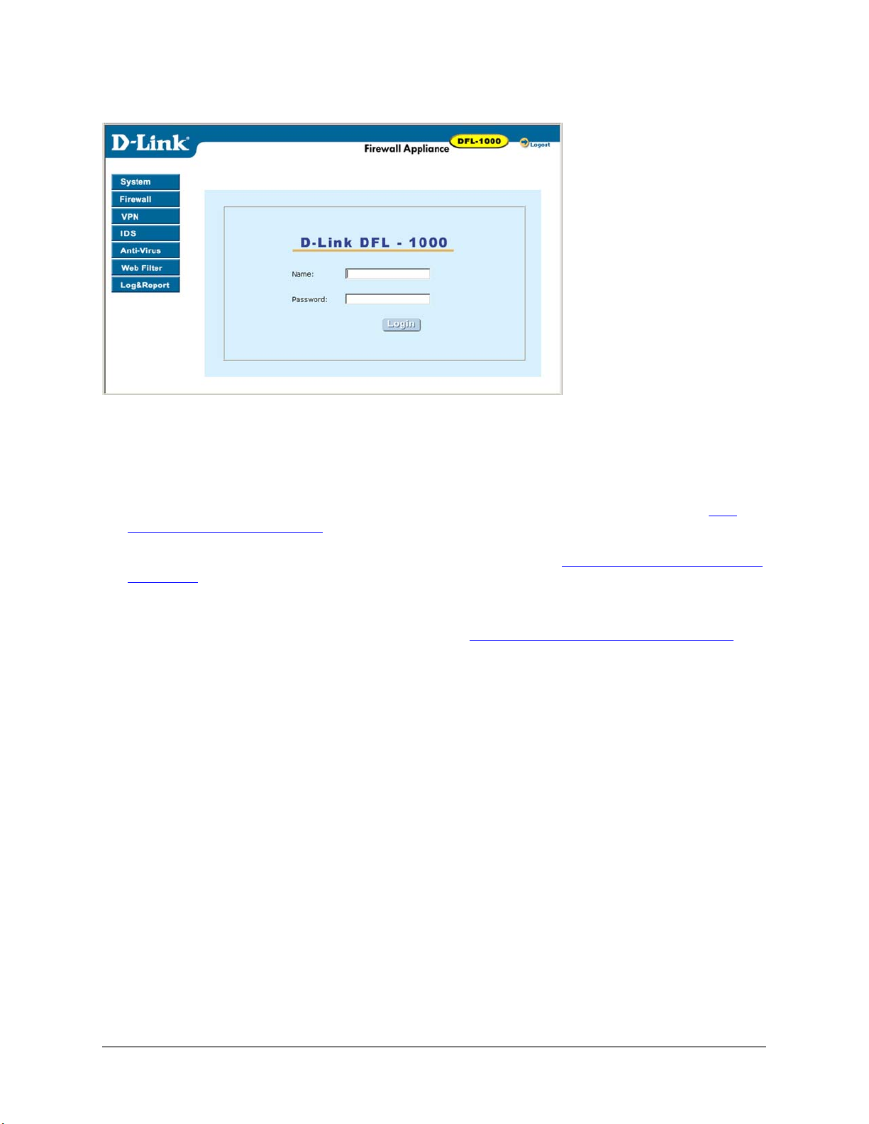
DFL-1000 login page
Starting the Quick Setup Wizard
To start the Quick Setup Wizard:
• Click the Wizard button at the upper right of the web-based manager.
• Select the operating mode: Network Address Translation (NAT) or Transparent.
If you selected Network Address Translation (NAT), use the information that you gathered in NAT
mode configuration information to fill in the wizard fields. Click the next button to step through the
wizard pages.
If you selected Transparent, use the information that you gathered in Transparent mode configuration
information to fill in the wizard fields. Click the next button to step through the wizard pages.
• Confirm your configuration settings and then click Finish and Close.
You have now completed the initial configuration of the DFL-1000, and you can proceed to connect
the DFL-1000 to your network using the information in Connecting the DFL-1000 to your network
.
Reconnecting to the web-based manager
After running the Quick Setup Wizard, if you changed the IP address of the internal interface or switched
to Transparent Mode, you must re-connect to the web-based manager using a new IP address:
• In NAT mode if you changed the IP address of the internal interface, browse to https:// followed by the
new IP address of the internal interface
• In Transparent mode, connect to the DMZ interface and browse to https:// followed by the
Transparent mode Management IP address
Otherwise you can reconnect to the web-based manager by browsing to https://192.168.1.99.
Configuring the DFL-1000 from the CLI
To connect to the DFL-1000 CLI you require:
• A computer with an available communications port
• A null modem cable with a 9-pin connector to connect to the communications port on the back panel
of the DFL-1000
• Terminal emulation software such as HyperTerminal for Windows
DFL-1000 User’s Manual
19
Page 20

The following procedure describes how to connect to the DFL-1000 CLI using Windows HyperTerminal
software. You can use any terminal emulation program.
Connecting to the CLI
• Connect the null modem cable to the communications port of your computer and to the
communications port on the back of the DFL-1000.
• Make sure the DFL-1000 is powered on.
• Start HyperTerminal, enter a name for the connection, and click OK.
• Specify the communications port in the Connect using field and click OK.
• Select the following port settings and click OK:
Bits per second
Data bits
Parity
Stop bits
Flow control
• Press Enter to connect to the DFL-1000 CLI.
The following prompt appears:
D-Link login:
• Type admin and press Enter.
The following prompt appears:
Type ? for a list of commands.
Use the procedures that follow to configure the DFL-1000 for NAT mode or Transparent mode operation.
The NAT mode and Transparent mode procedures are different. Choose the correct ones for your
installation. The NAT mode configuration procedures start next. The Transparent mode configuration
procedures begin at Configuring the DFL-1000 to run in Transparent mode
9600
8
None
1
None
.
Configuring the DFL-1000 to run in NAT mode
The procedures in this section describe how to use the CLI to configure the DFL-1000 to run in NAT
mode.
Configuring NAT mode IP addresses
• Login to the CLI if you are not already logged in.
• Set the IP address and netmask of the Internal interface to the Internal IP Address and Netmask that
you recorded in NAT mode IP addresses
set system interface internal ip <IP Address> <Netmask>
Example
set system interface internal ip 192.168.1.1 255.255.255.0
• Set the IP address and netmask of the External interface to the External IP Address and Netmask
that you recorded in NAT mode IP addresses
set system interface external ip <IP Address> <Netmask>
Example
set system interface external ip 204.23.1.5 255.255.255.0
• Set the IP address and netmask of the DMZ interface to the DMZ IP Address and Netmask that you
recorded in NAT mode IP addresses
DFL-1000 User’s Manual
. Enter:
. Enter:
. Enter:
20
Page 21

set system interface dmz ip <IP Address> <Netmask>
Example
set system interface dmz ip 192.168.1.1 255.255.255.0
• Confirm that the addresses are correct. Enter:
get system interface
The CLI lists the IP address and netmask settings for each of the DFL-1000 interfaces.
Configure the NAT mode default gateway
• Login to the CLI if you are not already logged in.
• Set the default route to the Default Gateway IP Address that you recorded in NAT mode IP addresses
Enter:
set system route add 0.0.0.0 0.0.0.0 gw <IP Address> dev external
Example
set system route add 0.0.0.0 0.0.0.0 gw 204.23.1.2 dev external
You have now completed the initial configuration of the DFL-1000 and you can proceed to connect
the DFL-1000 to your network using the information in Connecting the DFL-1000 to your network.
Configuring the DFL-1000 to run in Transparent mode
The procedures in this section describe how to use the CLI to configure the DFL-1000 to run in
Transparent mode.
Changing to Transparent mode
• Login to the CLI if you are not already logged in.
• Switch to Transparent mode. Enter:
set system status opmode 2
The following prompt appears:
D-Link login:
• Type admin and press Enter.
The following prompt appears:
Type ? for a list of commands.
• Confirm that the DFL-1000 has switched to Transparent mode. Enter:
get system status
The CLI displays the status of the DFL-1000. The last line shows the current operation mode.
Version:DFL-1000 2.20,build011,020315
virus-db:2.104(02/13/2002 15:20)
Serial Number:FGT2002801021023
Operation mode:transparent
.
Configuring Transparent mode management IP addresses
• Login to the CLI if you are not already logged in.
• Set the IP address and netmask of the DMZ interface to the Management IP Address and Netmask
that you recorded in Transparent mode IP addresses
set system interface dmz ip <IP Address> <Netmask>
Example
set system interface dmz ip 10.10.2.2 255.255.255.0
• Confirm that the address is correct. Enter:
get system interface
DFL-1000 User’s Manual
. Enter:
21
Page 22

The CLI lists the IP address and netmask settings for each of the DFL-1000 interfaces. The address
and netmask of the DMZ interface should be set to the Management IP Address and Netmask.
Configure the Transparent mode default gateway
• Login to the CLI if you are not already logged in.
• Add a default route set to the Default Gateway IP Address that you recorded in
addresses. Enter:
set system route add 0.0.0.0 0.0.0.0 gw <IP Address> dev external
Example
set system route add 0.0.0.0 0.0.0.0 gw 204.23.1.2 dev external
You have now completed the initial configuration of the DFL-1000 and you can proceed to connect
the DFL-1000 to your network using the information in Connecting the DFL-1000 to your network
follows.
Transparent mode IP
that
Connecting the DFL-1000 to your network
Once the initial configuration of the DFL-1000 is completed, you can connect the DFL-1000 between your
internal network and the Internet. The NAT mode and Transparent mode connection procedures are
different. Choose the correct one for your installation.
NAT mode connections
To connect the DFL-1000 running in NAT mode:
• Connect the Internal interface to the hub or switch connected to your internal network.
• Connect the External Interface to the public switch or router provided by your Internet Service
Provider.
• Optionally, connect the DMZ Interface to your DMZ network.
You can use a DMZ network to provide access from the Internet to a web or other server without
installing the servers on your internal network.
DFL-1000 User’s Manual
22
Page 23
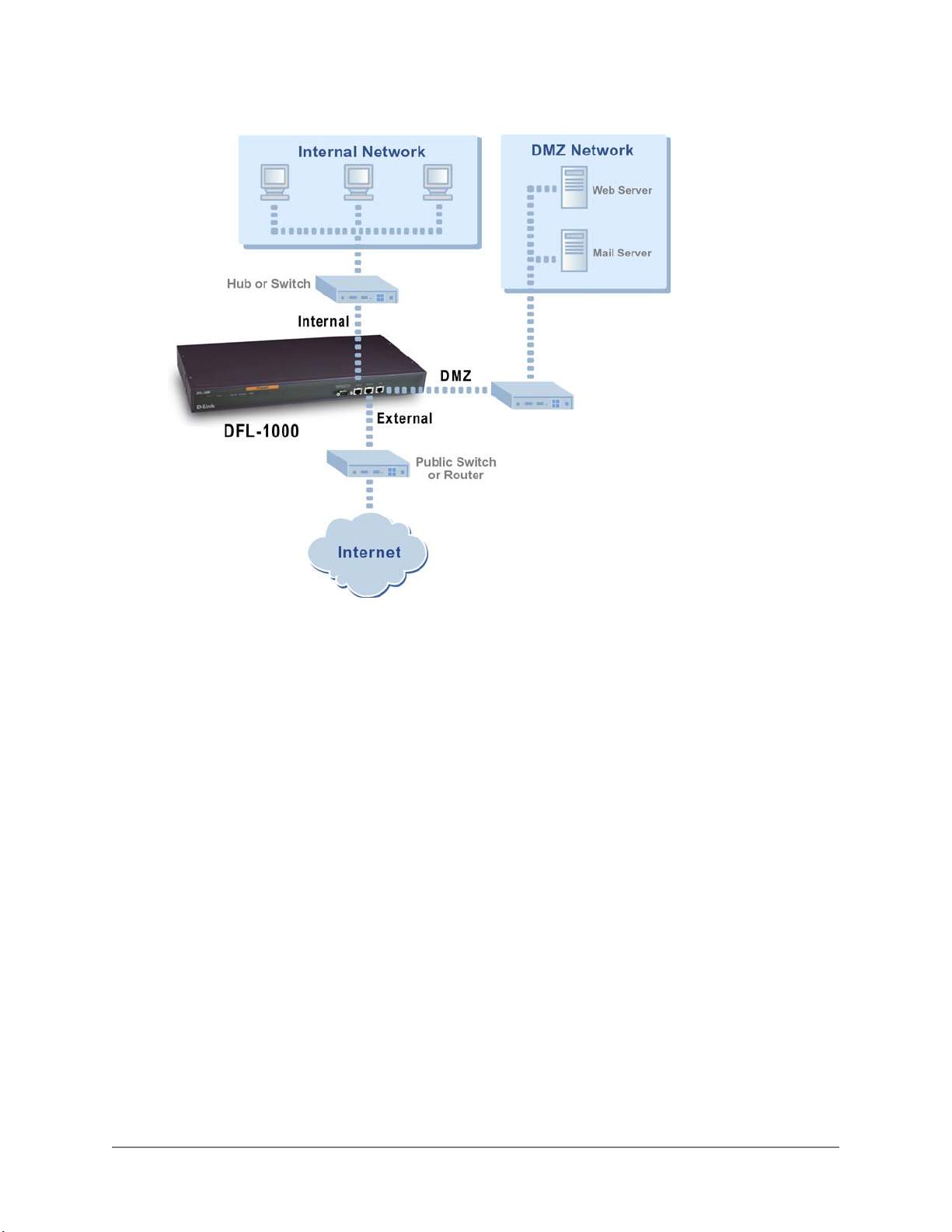
NAT mode connections:
Transparent mode connections
To connect the DFL-1000 running in Transparent mode:
• Connect the Internal interface to the hub or switch connected to your internal network.
• Connect the External Interface to the public switch or router provided by your Internet Service
Provider.
• Connect the DMZ Interface to your management computer.
You can either connect the DMZ interface directly to the Management computer using a cross-over
cable, or you can connect the DMZ interface and the management computer to a hub or switch.
DFL-1000 User’s Manual
23
Page 24
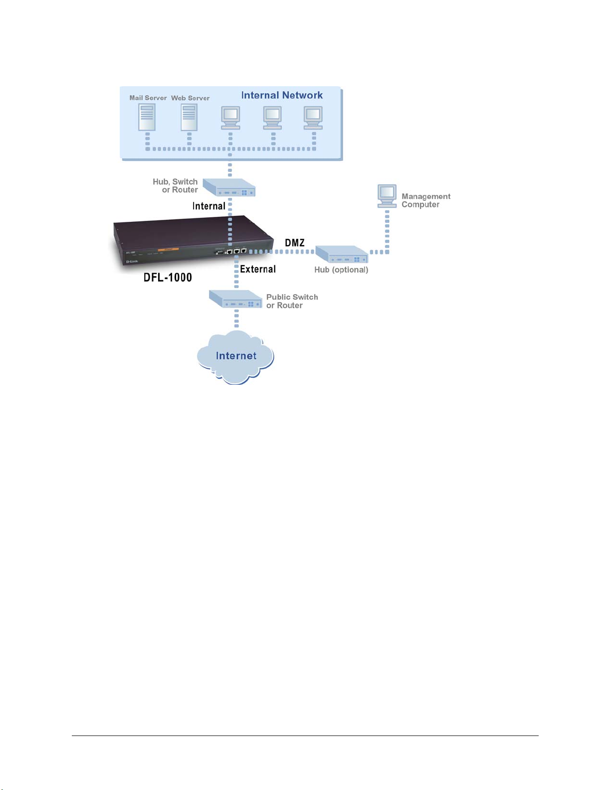
Transparent mode connections:
Configuring your internal network
If you are running the DFL-1000 in NAT mode, your internal network must be configured to route all
internet traffic to the address of the internal interface of the DFL-1000. This means changing the default
gateway address of all computers and routers connected directly to the internal network.
If you are using the DFL-1000 as the DHCP server for your internal network, configure the computers on
your internal network for DHCP. Use the internal address of the DFL-1000 as the DHCP server IP
address.
If you are running the DFL-1000 in Transparent mode, you do not have to make any changes to your
network.
Once the DFL-1000 is connected, make sure it is functioning properly by connecting to the internet from a
computer on your internal network. You should be able to connect to any internet address.
Completing the configuration
Use the information in this section to complete the initial configuration of the DFL-1000.
Configuring the DMZ interface
If you are planning on configuring a DMZ network, you may want to change the IP address of the DMZ
interface. Use the following procedure to configure the DMZ interface from the web-based manager.
• Log into the web-based manager.
• Go to System > Network > IP Address .
DFL-1000 User’s Manual
24
Page 25

• Change the DMZ IP address and netmask as required.
• Click Apply.
Setting the date and time
For effective scheduling and logging, the DFL-1000 date and time should be accurate. You can either
manually set the DFL-1000 time or you can configure the DFL-1000 to automatically keep its time correct
by synchronizing with a Network Time Protocol (NTP) server.
To set the DFL-1000 date and time, see Setting system date and time
.
DFL-1000 User’s Manual
25
Page 26

Firewall Configuration
This chapter describes how to use firewall policies to establish and control connectivity through the DFL1000 firewall. This chapter contains the following sections:
• Controlling connections from the Internet
• Controlling connections to the Internet
• Controlling connections to and from the DMZ
• Policies
• Addresses
• Services
• Schedules
• Users and authentication
• Virtual IPs
• IP/MAC binding
• Traffic shaping
• VPN pass through
Controlling connections from the Internet
By default, the DFL-1000 firewall denies access to the internal or DMZ network from the Internet. To
accept incoming connections, you must add policies to the Incoming policies list.
Use Incoming policies to give users on the Internet access to an Internet server (for example, your
organization's web server) that is protected by your firewall. When you are running the DFL-1000 in NAT
mode, you can locate these servers on the DMZ network or the internal network. When you are running
the DFL-1000 in Transparent mode, you can locate internet servers on the internal network only.
This section describes:
• Accepting incoming connections in NAT mode
• Accepting incoming connections in Transparent mode
• Denying incoming connections
• Arranging policies in the incoming policy list
Accepting incoming connections in NAT mode
The most secure way to operate an Internet server is to run the DFL-1000 in NAT mode and isolate the
server on your DMZ network. Isolating the server on the DMZ is more secure because from there the
server cannot be used to indirectly attack the internal network. You can, however, install the server on
your internal network if required.
Running the DFL-1000 in NAT mode hides the actual addresses of the computers on your internal and
DMZ networks from the Internet. To provide Internet access to a server on your DMZ or internal network,
you must add a Virtual IP that creates an association between the Internet IP address of the server and
the actual address of the computer on your DMZ or internal network that is running the server.
Once you have created a Virtual IP, you can add Incoming policies to accept connections to the server.
Adding an Incoming policy to accept connections
Use the following procedure to accept connections from the Internet to a server on the DMZ or the
Internal network:
• Add a Virtual IP for the server. See Adding Virtual IPs
DFL-1000 User’s Manual
.
26
Page 27
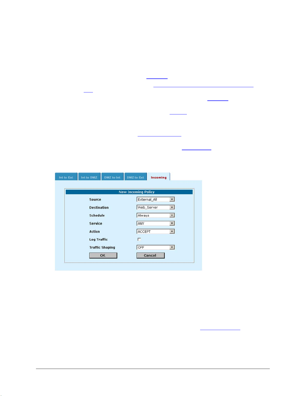
• Go to Firewall > Policy > Incoming .
• Click New to add a new incoming policy.
• Configure the policy.
Source
Destination
Schedule
Service
Action
Log Traffic
Traffic Shaping
External_All to accept connections to the server from anywhere on the Internet. You
can also select an external address that limits the source addresses that the policy
accepts connections from. See Addresses
Select the Virtual IP added in Step Add a Virtual IP for the server. See "Adding Virtual
IPs" .
Select a schedule to control when to accept connections. See Schedules
Select a service to match the Internet server. For example, if you are adding a policy
for a web server, set service to HTTP. See Services
Select Accept.
Optionally select Log Traffic to add messages to the traffic log whenever the policy
accepts a connection. See Logging and reporting
Optionally, select Traffic Shaping to control the bandwidth available to and set the
priority of the traffic processed by the policy. See Traffic shaping.
• Click OK to save the policy.
Adding an incoming policy:
.
.
.
.
Accepting incoming connections in Transparent mode
In transparent mode, the addresses on the internal network are routable from the internet so you do not
have to configure Virtual IP mapping. To accept connections to a server on the internal network, add the
address of the server to the internal address list and then add an incoming policy that accepts
connections to the internal address from the Internet.
Adding an incoming policy to accept connections
• Add the Internal address of the server to the Internal address list. See Adding addresses.
• Go to Firewall > Policy > Incoming .
• Click New to add a new incoming policy.
• Configure the policy.
DFL-1000 User’s Manual
27
Page 28

Source
Destination
Schedule
Service
Action
Log Traffic
Traffic
Shaping
External_All to accept connections to the server from anywhere on the Internet. You can also
select an external address that limits the source addresses that the policy accepts connections
from. See Addresses
Select the Internal address added in step Add the Internal address of the server to the Internal
address list. See "Adding addresses".
Select a schedule to control when to accept connections. See Schedules
Select a service to match the Internet server. For example, if you are adding a policy for a web
server, set service to HTTP. See Services
Select Accept.
Optionally select Log Traffic to add messages to the traffic log whenever the policy accepts a
connection.
Optionally, select Traffic Shaping to control the bandwidth available to and set the priority of the
traffic processed by the policy.
.
.
.
• Click OK to save the policy.
Denying incoming connections
Create policies that deny incoming connections to control access to the incoming policies that you have
already created.
You can use incoming policies to deny connections:
• From addresses on the Internet (see Addresses
• To addresses on your internal network (see Addresses
• To services (see Services
)
• According to a one-time or recurring schedule (see Schedules
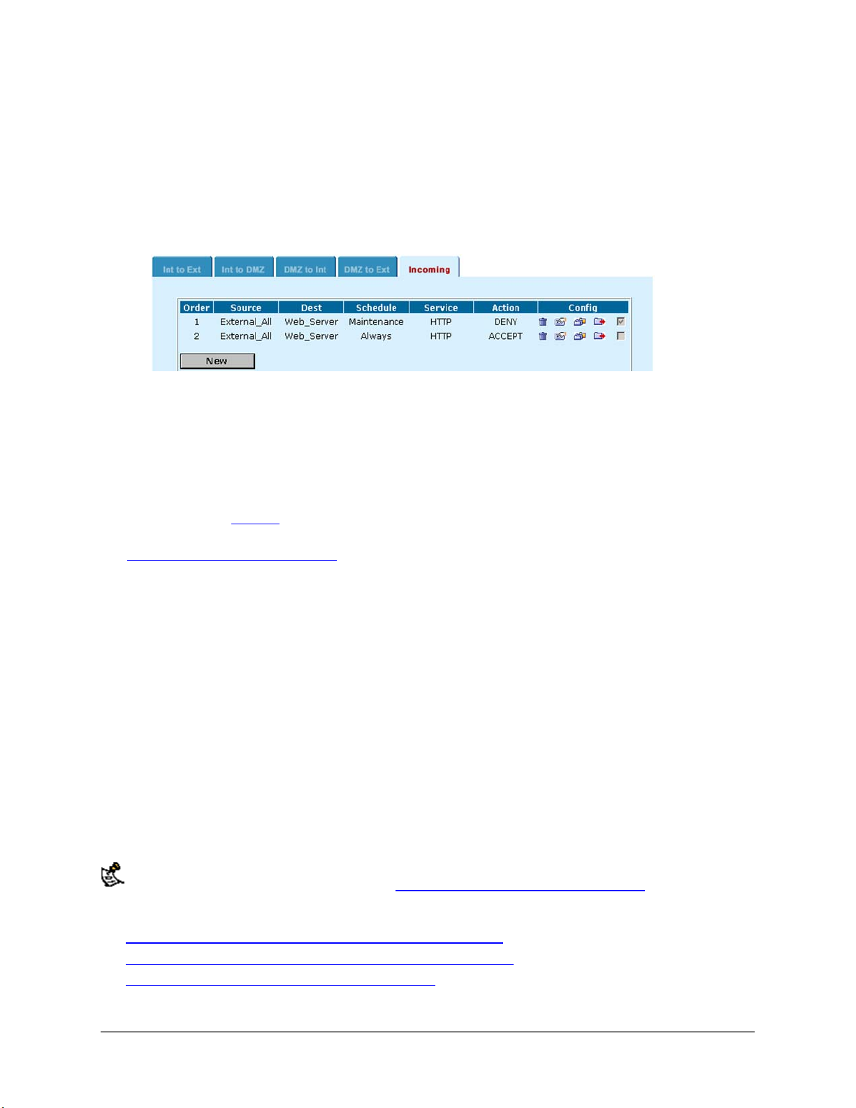
For example, you may want to periodically deny access to your public web server to allow for regular
maintenance. To do this, create a recurring schedule for the maintenance period. Then create a policy
that matches the original web server policy. Set the schedule of this policy to the maintenance schedule
and set Action to Deny.
Since policy matching works on a first-match principle, you must add the deny policy above the accept
policy in the policy list.
)
)
)
Adding an incoming policy to deny connections
• Add the schedule for denying access or add any addresses for which to deny connections. See
Schedules
• Go to Firewall > Policy > Incoming .
• Find the policy that you want to deny access to.
• Click Insert Policy before
policy to be denied.
• Configure the policy.
Source
Destination
Schedule
Service
Action
DFL-1000 User’s Manual
.
for the policy to be denied. This inserts a new policy in the list above the
Select the External address that matches the policy to deny.
Select the Virtual IP (NAT mode) or Internal address (Transparent mode) that matches the
policy to deny.
Select a schedule to control when the policy denies connections.
Select the service that matches the service of the policy to deny.
Select Deny so that the DFL-1000 denies connections defined by the policy.
28
Page 29
Log Traffic
Traffic
Shaping
Optionally select Log Traffic to add messages to the traffic log whenever the policy accepts a
connection.
Optionally, select Traffic Shaping to control the bandwidth available to and set the priority of
the traffic processed by the policy.
• Click OK to save the policy.
The deny policy is added to the policy list above the policy that accepts connections.
Example policy to deny access:
Arranging policies in the incoming policy list
Arrange policies in the incoming policy list to make sure that the policies function as you expect them to.
When the DFL-1000 receives a connection attempt from the Internet, it decides whether to accept or deny
the connection by matching it with a policy on the Incoming policy list. The first policy to match the
connection attempt is applied. Because policies are selected on a first match basis, you must arrange
policies in the policy list so that they have the effect that you expect them to. In general, you should
arrange policies that deny connections above policies that accept connections. For more information on
policy matching, see Policies.
From the policy list you can re-arrange policies, delete policies, and edit policies. For more information,
see Arranging policies in the policy list
.
Controlling connections to the Internet
By default, the DFL-1000 accepts all connections from the internal network to the Internet. If you do not
want to enforce restrictions on access to the Internet, you do not have to change anything. The default
policy accepts connections from any address on the internal network to any address on the Internet at
any time, and for any service.
If you want to control connections to the Internet, you have three choices:
• Add exceptions to the default policy that deny connections
• Add exceptions to the default policy that require authentication
• Delete the default policy and then add policies that accept connections
In NAT mode, policies for connections from the internal network to the Internet are added to the Internal
to External (Int to Ext) policies list. In Transparent mode, these policies are added to the Outgoing policies
list.
In NAT mode you can also create policies for connections from the Internal network to the DMZ network.
Policies for these connections are described in Controlling connections to and from the DMZ
This section describes:
• Denying connections to the Internet from the internal network
• Accepting connections to the Internet from the internal network
• Requiring authentication to connect to the Internet
.
DFL-1000 User’s Manual
29
Page 30

• Arranging policies in the Int to Ext and Outgoing policy list
Denying connections to the Internet from the internal network
Create policies that deny connections to the Internet from the internal network to restrict the full access to
the Internet granted by the default policy.
You can use policies to deny connections:
• From addresses on your internal network (see Adding addresses
• To addresses on the Internet (see Adding addresses
• To services (see Services
)
)
• According to a one-time or recurring schedule (see Schedules
Since policy matching works on a first-match principle, you must add deny policies above the default
policy. You must also add deny policies above matching policies that accept connections.
Adding a policy to deny connections
• Add addresses, services, or schedules as required.
• Go to Firewall > Policy > Int to Ext . (In Transparent mode go to Firewall > Policy > Outgoing .)
• Click New to add a policy.
You can also click Insert Policy before
policy.
• Configure the policy.
Source
Destination
Schedule
Service
Action
Log Traffic
Traffic
Shaping
Select the Internal address from which to deny connections.
Select the Internet address to which to deny connections.
Select a schedule to control when the policy denies connections.
Set Service to the service to deny.
Select Deny.
Optionally select Log Traffic to add messages to the traffic log whenever the policy accepts a
connection.
Optionally, select Traffic Shaping to control the bandwidth available to and set the priority of
the traffic processed by the policy.
on a policy in the list to add the new policy above a specific
)
)
• Click OK to save the policy.
DFL-1000 User’s Manual
30
Page 31
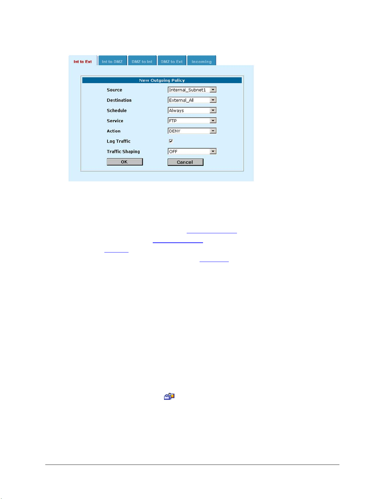
Policy to deny FTP connections to the Internet from an internal subnet:
Accepting connections to the Internet from the internal network
Create policies that accept connections to the Internet from the internal network to control the
connections that are available.
You can use policies to accept connections:
• From addresses on your internal network (see Adding addresses
• To addresses on the Internet (see Adding addresses
• To services (see Services
)
)
• According to a one-time or recurring schedule (see Schedules
Policies that accept connections can be used in the following ways:
• Add policies that accept connections as exceptions to policies that deny connections
For example, if a policy denies connections to a subnet, you can add a policy that accepts
connections from one of the computers on the subnet. Policies that accept connections in this way
must be added to the policy list above the connections that they are exceptions to.
• Delete the default policy and then add policies to accept only the connections that you want the
firewall to accept
In this way you can limit Internet access to that allowed in the policies that you create. You must
delete the default policy because if it remains in the policy list, all connections that do not match a
policy will be accepted by the default policy.
)
)
Adding a policy to accept connections
• Add addresses, services, or schedules as required.
• Go to Firewall > Policy > Int to Ext . (In Transparent mode go to Firewall > Policy > Outgoing .)
• Click New to add a policy.
You can also click Insert Policy before
policy.
• Configure the policy.
Source
Destination
DFL-1000 User’s Manual
Select the Internal address from which to accept connections.
Select the Internet address for which to accept connections.
on a policy in the list to add the new policy above a specific
31
Page 32

Schedule
Service
Action
Log Traffic
Traffic
Shaping
Select a schedule to control when the policy accepts connections.
Set Service to the service to accept.
Select Accept.
Optionally select Log Traffic to add messages to the traffic log whenever the policy accepts a
connection.
Optionally, select Traffic Shaping to control the bandwidth available to and set the priority of
the traffic processed by the policy.
• Click OK to save the policy.
Requiring authentication to connect to the Internet
When running the DFL-1000 in NAT mode, you can configure policies to require users on the internal
network to enter a user name and password to access the Internet. To require authentication you must
add users to the firewall configuration, see Adding users
You can add policies to require user authentication for connections:
• From addresses on your internal network (see Adding addresses
• To addresses on the Internet (see Adding addresses
• Using certain services (see Services
)
• During a one-time or recurring schedule (see Schedules
Adding a policy to require authentication
Use the following procedure to require uses to authenticate before being able to access the internet:
• Add users to the firewall. See Users and authentication
• Go to Firewall > Policy > Int to Ext .
• Click New to add a policy.
• Configure the policy.
Source
Destination
Schedule
Service
Action
Log Traffic
Traffic
Shaping
Select the Internal address that users must authenticate from.
Select the Internet address that users must authenticate before connecting to.
Select a schedule to control when to require authentication.
Select the service for which to require authentication.
Select Auth.
Optionally select Log Traffic to add messages to the traffic log whenever the policy accepts a
connection.
Optionally, select Traffic Shaping to control the bandwidth available to and set the priority of
the traffic processed by the policy.
.
)
)
)
.
• Click OK to save the policy.
Arranging policies in the Int to Ext and Outgoing policy list
Arrange policies in the Int to Ext policy list (NAT mode) or the Outgoing policy list (Transparent mode) to
make sure that the policies function as you expect them to. When the DFL-1000 receives a connection
attempt from your internal network, it decides whether to accept or deny the connection or require
authentication by matching it with a policy on the Int to Ext or Outgoing policy list. The first policy to match
the connection attempt is applied. In general, you should arrange policies that deny connections above
policies that accept connections. For more information on policy matching, see Policies.
DFL-1000 User’s Manual
32
Page 33

From the policy list you can re-arrange policies, delete policies, and edit policies. For more information,
see Arranging policies in the policy list.
Controlling connections to and from the DMZ
By default the DFL-1000 firewall denies connections between the DMZ and the Internet and between the
DMZ and the internal network. You can configure the firewall to accept, deny, or require authentication for
connections between these networks by adding policies to the following policy lists:
• Internal to DMZ (Int to DMZ)
Int to DMZ policies control connections from the internal network to the DMZ network. Users on your
internal network would use a connection controlled by an Int to DMZ policy to access your Internet
web server if it is installed on your DMZ.
• DMZ to Internal (DMZ to Int)
DMZ to Int policies control connections from the DMZ network to the internal network. An e-
commerce web server on your DMZ would use a connection controlled by a DMZ to Int policy to
transfer order information to a database server on your internal network.
• DMZ to External (DMZ to Ext)
DMZ to Ext policies allow servers on the DMZ network to connect to servers on the Internet. For
example, if you install an SMTP server on your DMZ it must be able to connect to SMTP servers on
the Internet to forward email. You may also have other requirements for computers on the DMZ to be
able to connect to the Internet.
To configure DMZ policies, you must first add DMZ addresses for the servers on your DMZ to the firewall
configuration. See Adding addresses
Once the DMZ addresses have been added, you can add and organize DMZ-related policies in the same
way as Int to Ext, Outgoing, and Incoming policies. For examples, see Controlling connections from the
Internet and Controlling connections to the Internet. For general information about policies, see Policies.
.
Policies
Firewall policies are instructions that the firewall uses to decide what to do with a connection request.
Policies contain information used to identify the characteristics of a connection request. Identifying
information consists of the source address, destination address, and network service (or port number)
used by the connection request. Identifying information also includes the time and date on which the
firewall receives the connection request.
This section contains the following information about policies:
• Policy information
• Default policy
• Adding policies
• Editing policies
• Policy matching
• Arranging policies in the policy list
Policy information
Policies direct the firewall to perform actions when a connection request matches the identifying
information. A policy can specify that the firewall accepts, denies, or requests authentication for the
connection. A policy can also record traffic log messages when the policy processes traffic and apply
traffic shaping to the traffic controlled by the policy.
DFL-1000 User’s Manual
33
Page 34
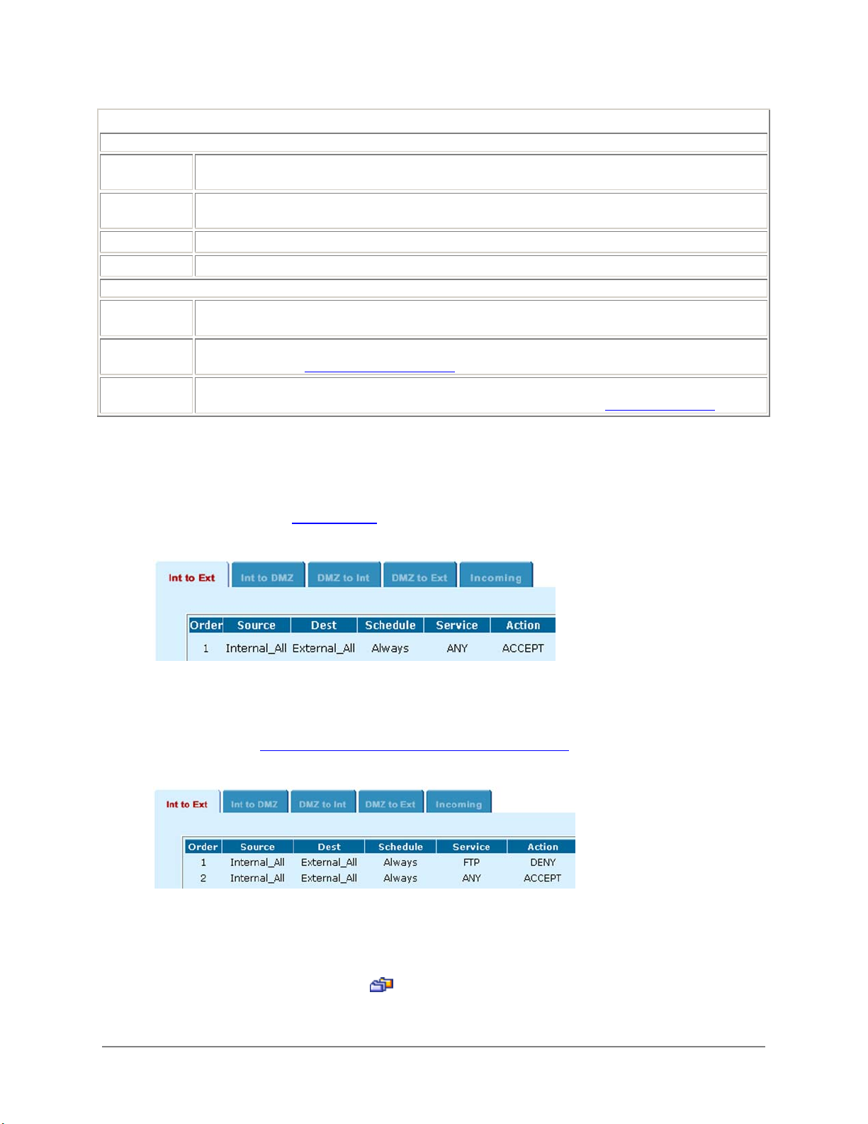
The parts of a DFL-1000 policy
Identifying information
Source
Address
Destination
Address
Schedule The time or date on which a policy is active.
Service The network service to be provided through the firewall.
Action
Action
Log Traffic
Traffic Shaping
The IP address from which a user or service can connect to the firewall.
The location to which a user or service is attempting to connect when intercepted by the firewall.
The response of the firewall. The firewall can accept the connection, deny the connection, or require
the user attempting to make the connection to provide authentication.
Log Traffic adds messages to the traffic log whenever the policy processes traffic. For information
about logging, see See Logging and reporting
Traffic Shaping can be used to control the bandwidth available to, and set the priority of the traffic
processed by the policy. For more information about traffic shaping, see See Traffic shaping
.
Default policy
The default policy accepts connections from all computers at any source address on the internal network
and grants them access to any services on the external network (usually the Internet). The default policy
appears in the Int to Ext policy list when running in NAT mode and in the Outgoing policy list when
running in Transparent mode. Default policy
shows the default policy.
Default policy:
Adding policies
Policies can be simple to add. For example, you can prevent users on the internal network from
connecting to FTP servers on the Internet by adding an Int to Ext policy that denies connections to the
FTP service as shown in Sample Int to Ext policy to deny FTP connections
Sample Int to Ext policy to deny FTP connections:
To add a policy:
• Go to Firewall > Policy .
• Click the tab corresponding to the type of policy to add.
• Click New to add a policy.
You can also click Insert Policy before
• Configure the policy.
on a policy in the list to add the new policy above this one.
.
DFL-1000 User’s Manual
34
Page 35

• Click OK to save the policy.
Editing policies
To edit a policy:
• Go to Firewall > Policy .
• Click the tab corresponding to the type of policy to edit.
• Choose a policy to edit and click Edit
• Edit the policy settings as required.
You can change any of the policy settings as required.
• Click OK to save your changes.
.
Policy matching
For every connection attempt, the DFL-1000 must choose the policy to apply to the connection. To match
a policy with a connection attempt, the DFL-1000 extracts the source address, destination address, and
service (or port number) from the connection attempt. Then the DFL-1000 begins at the top of the policy
list and searches for the first policy with matching addresses, service, and with a schedule that matches
the time at which the connection attempt was received. The first policy that matches is applied to the
connection attempt. If no policy matches, the connection is denied.
The default policy accepts all connection attempts from the internal network to the Internet. From the
internal network, users can browse the web, use POP3 to get email, use FTP to download files through
the DFL-1000 and so on. If the default policy is at the top of the internal policy list, the DFL-1000 allows
all connections from the internal network to the Internet because all connections match with the default
policy. Any policies in the list below the default policy are never matched.
For the policy to block FTP connections shown in Sample Int to Ext policy to deny FTP connections
effective, it must be moved above the default policy in the policy list. Then, all FTP connection attempts
from the internal network would match the FTP policy and be blocked. Connection attempts for all other
kinds of services would not match with the FTP policy but they would match with the default policy. So the
firewall would accept all other connections.
to be
Arranging policies in the policy list
Once you have added policies to a policy list, you can use the following steps to arrange them as required.
• Go to Firewall > Policy .
• Click the tab corresponding to the policy list to arrange.
• Choose a policy to move and click Move To
• Type a number in the Move to field to specify where in the policy list to move the policy to and click
OK.
• Click Delete
to remove a policy from the list.
to change its order in the policy list.
Addresses
All DFL-1000 policies require source and destination IP addresses. By default, the DFL-1000 includes two
addresses that cannot be edited or deleted:
• Internal_All on the Internal address list which represents the IP addresses of all of the computers on
your internal network
• External_All on the External address list which represents the IP addresses of all of the computers on
the Internet
You can add the following types of addresses:
DFL-1000 User’s Manual
35
Page 36
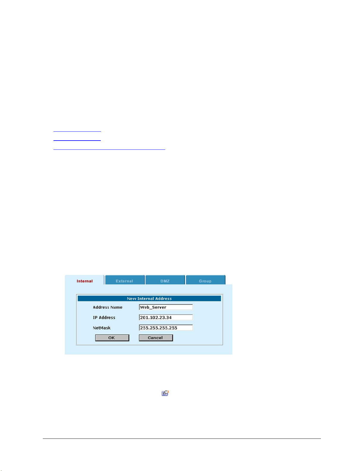
• Internal addresses define addresses on your internal network
Internal addresses can be added to the source address of an Int to Ext, Int to DMZ or Outgoing policy.
Internal addresses can be added to the destination address of a DMZ to Int policy.
• External addresses define addresses on the Internet
External addresses can be added to the source address of an Incoming policy or to the destination
addresses of Int to Ext and DMZ to Ext policies.
• DMZ addresses define addresses on the DMZ
DMZ addresses can be added to the source address of a DMZ to Int and DMZ to Ext policy. DMZ
addresses can be added to the destination address of an Int to DMZ policy.
This section describes:
• Adding addresses
• Editing addresses
• Organizing addresses into address groups
Adding addresses
• Go to Firewall > Address .
Click the Internal, External, or DMZ tab corresponding to the type of address you want to add.
• Click New to add a new address.
• Enter an Address Name to identify the address.
• Add the IP Address.
The IP Address can be the IP address of a single computer (for example, 192.45.46.45) or the
address of a subnetwork (for example, 192.168.1.0).
• Add the NetMask.
The Netmask should correspond to the address. The Netmask for the IP address of a single
computer should be 255.255.255.255, The Netmask for a subnet should be 255.255.255.0.
• Click OK to add the address.
Example internal address:
Editing addresses
• Go to Firewall > Address .
Click the Internal, External, or DMZ tab corresponding to the type of address you want to edit.
• Choose an address to edit and click Edit
• Make the required changes and click OK to save your changes.
.
DFL-1000 User’s Manual
36
Page 37
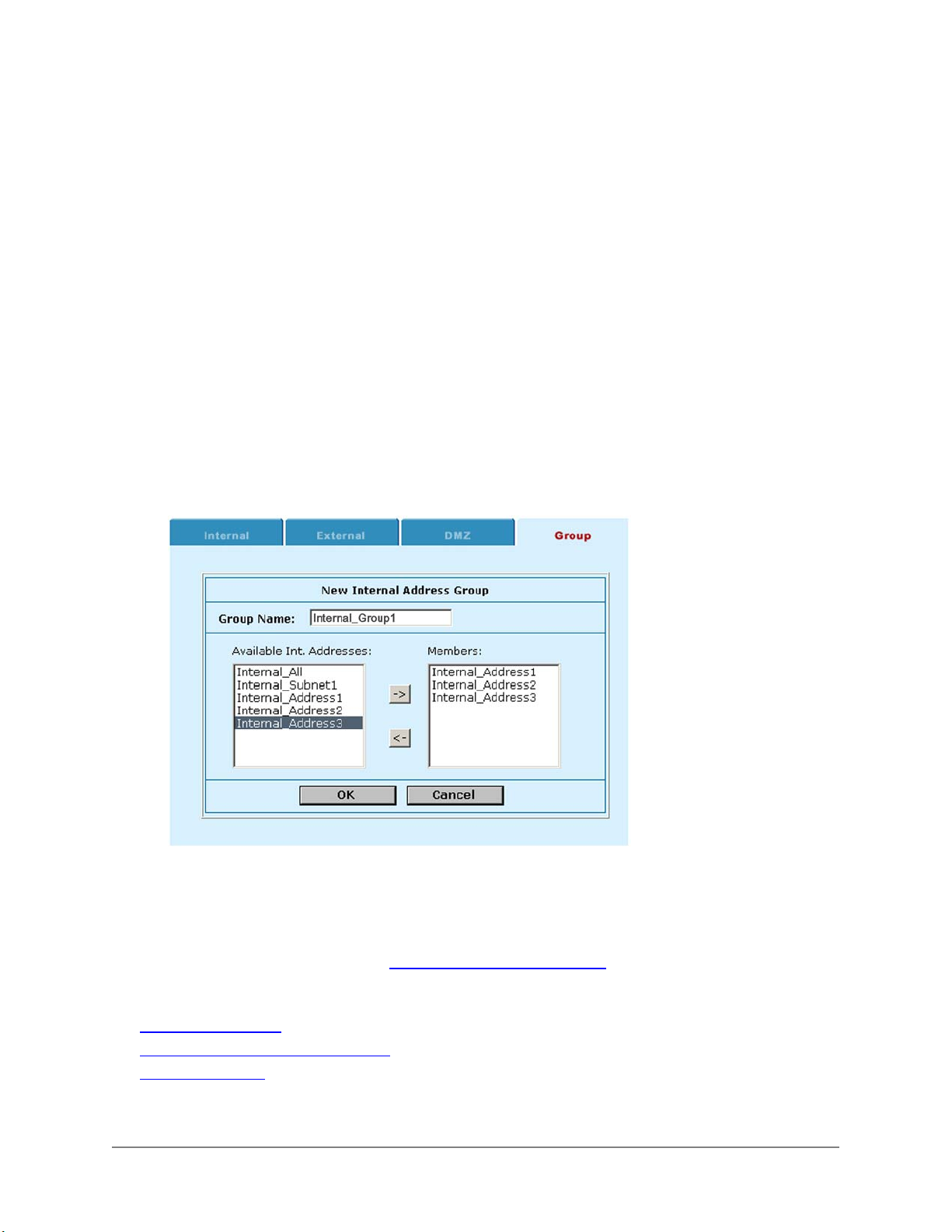
Organizing addresses into address groups
You can organize related addresses into address groups to make it easier to add policies. If you add 3
addresses, and then add them to an address group, you only have to add one policy for these addresses
rather than a separate policy for each address.
You can add External, Internal, and DMZ address groups.
To add an address group:
• Go to Firewall > Address > Group .
• Choose the type of address group to add.
Click New Int. Group to create an internal address group.
Click New Ext. Group to create an external address group.
Click New DMZ Group to create a DMZ address group.
• Enter a Group Name to identify the address group.
• To add addresses to the address group, select an address from the Available Addresses list and click
the right arrow to add it to the Members list.
• To remove addresses from the address group, select an address from the Members list and click the
left arrow to remove it from the group.
• Click OK to add the address group.
Example internal address group
Services
Use services to control the types of communication accepted or denied by the firewall. You can add any
of the pre-configured services listed in DFL-1000 pre-defined services to a policy. You can also create
your own custom services and add services to service groups.
This section describes:
• Pre-defined services
• Providing access to custom services
• Grouping services
DFL-1000 User’s Manual
37
Page 38

Pre-defined services
The DFL-1000 pre-defined services are listed in DFL-1000 pre-defined services.
DFL-1000 pre-defined services
Service
name
ANY Match connections on any port. all
DNS Domain name servers for looking up domain names.
FINGER Finger service. tcp/79:0-65535
FTP FTP service for transferring files. tcp/20-21:0-65535
GOPHER Gopher communication service. tcp/70:0-65535
HTTP HTTP service for connecting to web pages. tcp/80:0-65535
HTTPS
IMAP
IRC Internet relay chat for connecting to chat groups. tcp/6660-6669:0-65535
NFS Network file services for sharing files.
NNTP Protocol for transmitting Usenet news. tcp/119:0-65535
NTP
PING For testing connections to other computers. udp/0:0-65535, 8:0-65535
POP3
QUAKE
RAUDIO For streaming real audio multi-media traffic. udp/7070:0-65535
RLOGIN tcp/513:0-65535
SMTP For sending mail between email servers on the Internet. tcp/25:0-65535
SNMP For communicating system status information.
SSH
TELNET
VDOLIVE For VDO Live streaming multimedia traffic. udp/7000:0-65535
WAIS tcp/210:0-65535
XWINDOWS
Description Protocol, source and destination ports
tcp/53:0-65535
udp/53:0-65535
SSL service for secure communications with web
servers.
IMAP email protocol for reading email from an IMAP
server.
Network time protocol for synchronizing a computer's
time with a time server.
POP3 email protocol for downloading email from a
POP3 server.
For connections used by the popular Quake multi-player
computer game.
SSH service for secure connections to computers for
remote management.
Telnet service for connecting to a remote computer to
run commands.
tcp/6000:0-65535
tcp/443:0-65535
tcp/143:0-65535
tcp/111:0-65535, 2049:0-65535
udp/111:0-65535, 2049:0-65535
tcp/123:0-65535
udp/123:0-65535
tcp/110:0-65535
udp/110:0-65535
udp/26000:0-65535, 27000:0-65535,
27910:0-65535, 27960:0-65535
tcp/161-162:0-65535
udp/161-162:0-65535
tcp/22:0-65535
udp/22:0-65535
tcp/23:0-65535
DFL-1000 User’s Manual
38
Page 39
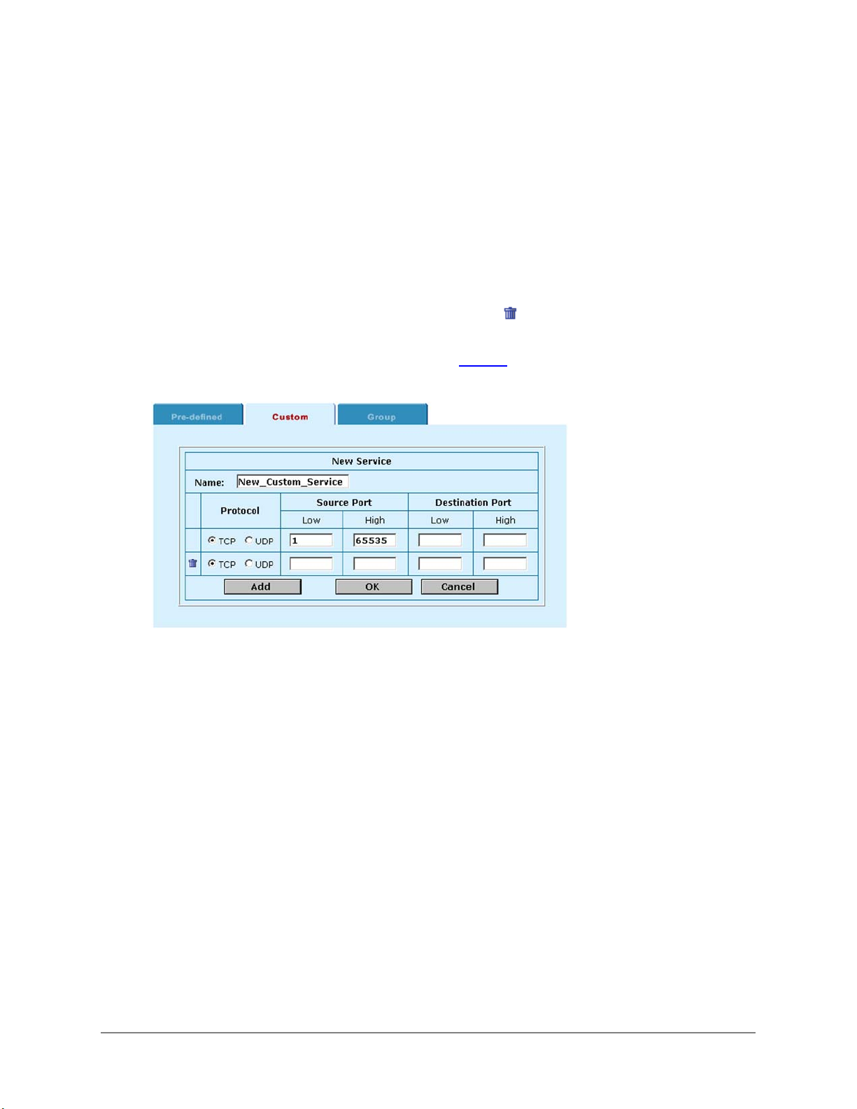
Providing access to custom services
Add a custom service if you need to create a policy for a service that is not in the predefined services list.
Use the following procedure to add your own custom service.
• Go to Firewall > Service > Custom .
• Click New.
• Enter a Name for the service. This name appears in the service list used when you add a policy.
• Select the protocol (either TCP or UDP) used by the service.
• Specify a port number range for the service by adding the low and high port numbers. If the service
uses one port number, add this number to both the Low and High fields.
• If the service has more than one port range, click Add to specify additional protocols and port ranges.
If you mistakenly add too many port range rows, click delete
• Click OK to add the custom service.
You can now add this custom service to a policy (see Policies
Adding a custom service:
to remove the extra row.
).
Grouping services
To make it easier to add policies, you can create groups of services and then add one policy to provide
access to or block access for all the services in the group. A service group can contain pre-defined
services and custom services in any combination. You cannot add service groups to another service
group.
To add a service group:
• Go to Firewall > Service > Group .
• Click New.
• Enter a Group Name to identify the group. This name appears in the service list used when you add a
policy.
• To add services to the service group, select a service from the Available Services list and click the
right arrow to copy it to the Members list.
• To remove services from the service group, select a service from the Members list and click the left
arrow to remove it from the group.
1. Click OK to add the service group.
DFL-1000 User’s Manual
39
Page 40
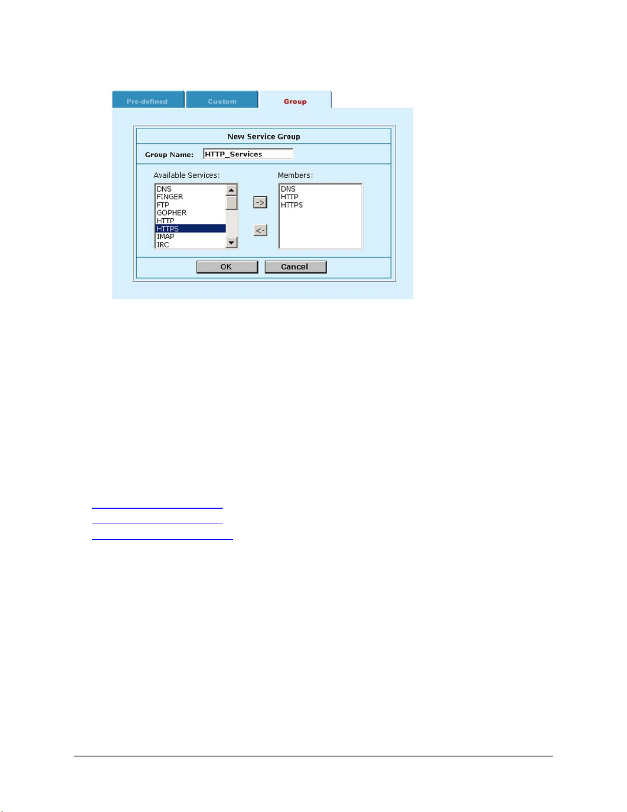
Adding a service group:
Schedules
Use scheduling to control when policies are active or inactive. You can create one-time schedules and
recurring schedules. You can use one-time schedules to create policies that are effective once only for
the period of time specified in the schedule. Recurring schedules repeat weekly. You can use recurring
schedules to create policies that are effective only at specified times of the day or on specified days of the
week.
In some cases, you may be required to create multiple schedules to schedule a policy to be active for
more than a single day. For example, for a policy to be valid from Monday at 5:00 pm until Tuesday at
9:00 am, you must create two schedules and then two policies, one for each schedule. The first schedule
should run from Monday evening at 5:00 pm until midnight and the second from midnight until 9:00 am on
Tuesday morning.
This section describes:
• Creating one-time schedules
• Creating recurring schedules
• Applying a schedule to a policy
Creating one-time schedules
You can create a one-time schedule that activates or deactivates a policy for a specified period of time.
For instance, your firewall may be configured with the default Internal to External policy that allows
access to all services on the Internet at all times. You can add a one-time schedule to block access to the
Internet during a holiday period. The following procedure describes how to create a one-time schedule
with a start date at the start of the holiday and an end date at the end of the holiday.
• Go to Firewall > Schedule > One-time .
• Click New.
• Specify a name for the schedule.
• Specify the Start date and time for the schedule.
Set start and stop times to 00 for the schedule to cover the entire day.
• Specify the Stop date and time for the schedule.
One-time schedules use the 24-hour clock.
DFL-1000 User’s Manual
40
Page 41
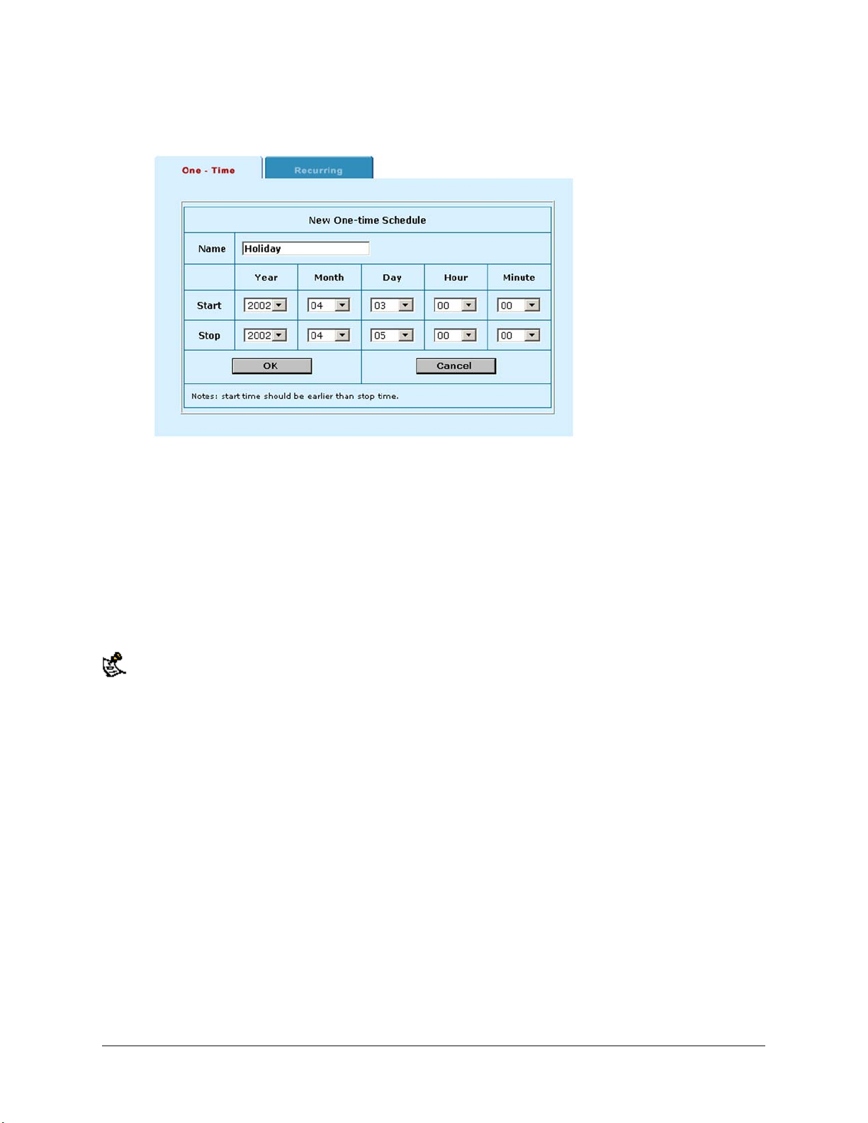
• Click OK to add the One-time schedule.
Sample one-time schedule:
Creating recurring schedules
You can create a recurring schedule that activates or deactivates policies at specified times of the day or
on specified days of the week. For instance, you may wish to prevent internet use outside of working
hours by creating a recurring schedule.
• Go to Firewall > Schedule > Recurring .
• Click New to create a new schedule.
• Specify a name for the schedule.
• Select the days of the week that are working days.
• Set the Start Hour and the End Hour to the start and end of the work day.
The Recurring schedule uses a 24-hour clock.
• Click OK.
DFL-1000 User’s Manual
41
Page 42
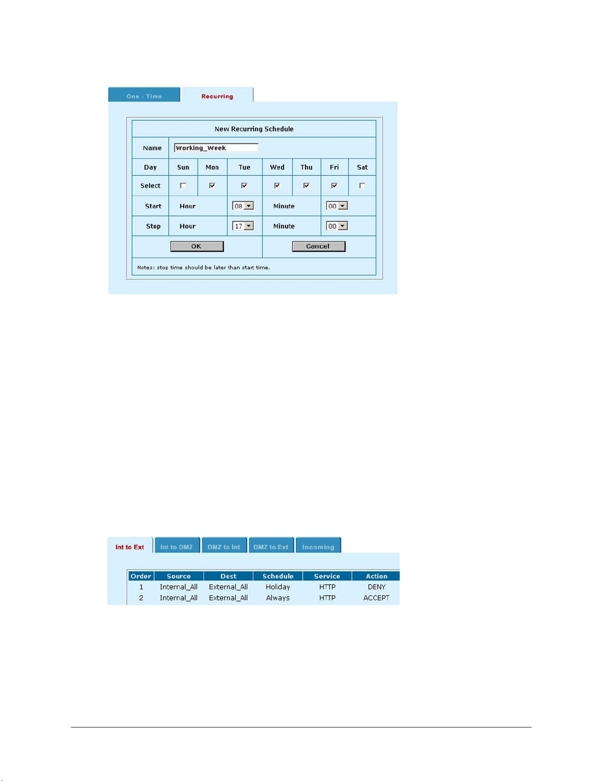
Sample recurring schedule:
Applying a schedule to a policy
Once you have created schedules you can add them to policies to schedule when the policies are active.
Create a policy containing the schedule, and then arrange the policy in the policy list for the schedule to
be effective.
• Go to Firewall > Policy .
• Click the tab corresponding to the type of policy to add.
• Click New to add a policy.
• Configure the policy as required.
• Add a schedule by selecting it from the Schedule list.
• Click OK to save the policy
• Arrange the policy in the policy list to have the effect that you expect.
For example, to use a one-time schedule to deny access to another policy, add a policy that matches
the other policy in every way. Choose the one-time schedule that you added and set Action to Deny.
Then you must arrange the policy containing the one-time schedule in the policy list above the policy
to be denied.
Arranging a one-time schedule in the policy list to deny access:
Users and authentication
You can configure the DFL-1000 to require users to authenticate (enter a user name and password) to
access services through the firewall. To configure authentication you need to add user names and
passwords to the firewall and then add policies that require authentication. When a connection attempt is
matched by a policy requiring authentication, the user requesting the connection must enter a user name
DFL-1000 User’s Manual
42
Page 43
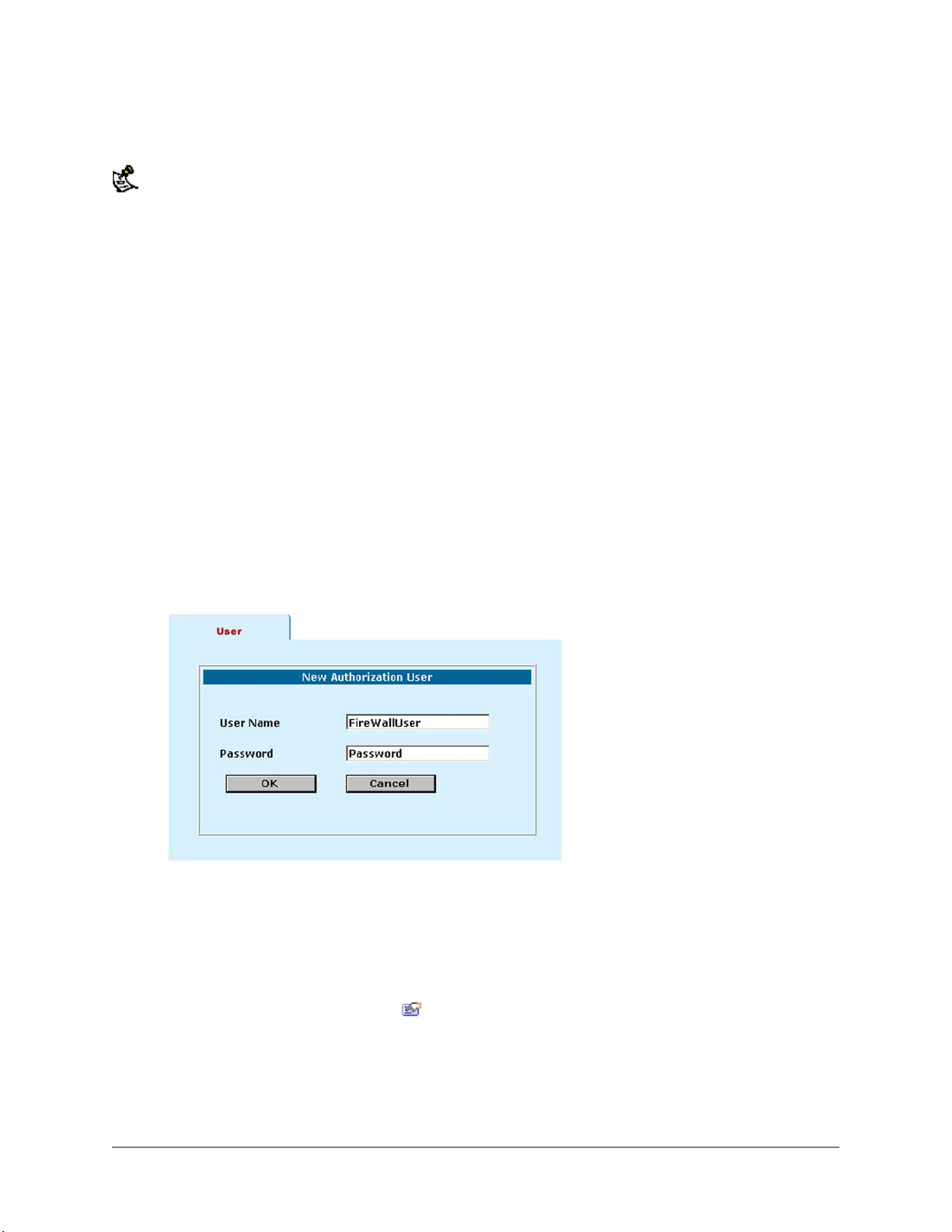
and password that matches that of a user added to the firewall to be allowed to connect through the
firewall.
Requiring passwords is not supported in Transparent mode.
You can add authentication to any Int to Ext, Int to DMZ, DMZ to Int, and DMZ to Ext policy, but not to
Incoming policies. You can require authentication for connections to the Internet from the internal network
or from the DMZ. You can also require authentication for connections to the DMZ from the internal
network or for connections to the internal network from the DMZ.
Users can only enter passwords using HTTP, FTP, or Telnet. If users are required to enter a user name
and password to access the Internet, they must connect to the firewall using a web browser, FTP, or
Telnet to enter their user name and password.
A user's authentication remains valid for an idle time out of 15 minutes. If the user does not access
services through the firewall for more than 15 minutes, they must enter their user name and password
again for access.
Adding users
• Go to Firewall > Users .
• Click New.
• Enter a User Name and Password to add users to the DFL-1000.
The password must be at least 6 characters long and may contain numbers (0-9) and upper and
lower case letters (A-Z, a-z) but no spaces.
• Click OK.
Adding a user
Adding authentication to a policy
Once you have added user names and passwords you can add or edit policies to require authentication.
• Go to Firewall > Policy .
• Click the tab corresponding to the type of policy to add.
You can add authentication to Int to Ext, Int to DMZ, DMZ to Int, and DMZ to Ext policies.
• Click New to add a policy or click Edit
• Configure the policy as required.
• Set Action to Auth.
• Click OK to save the policy
• Arrange the policy in the policy list to have the effect that you expect.
to edit a policy to add authentication.
DFL-1000 User’s Manual
43
Page 44
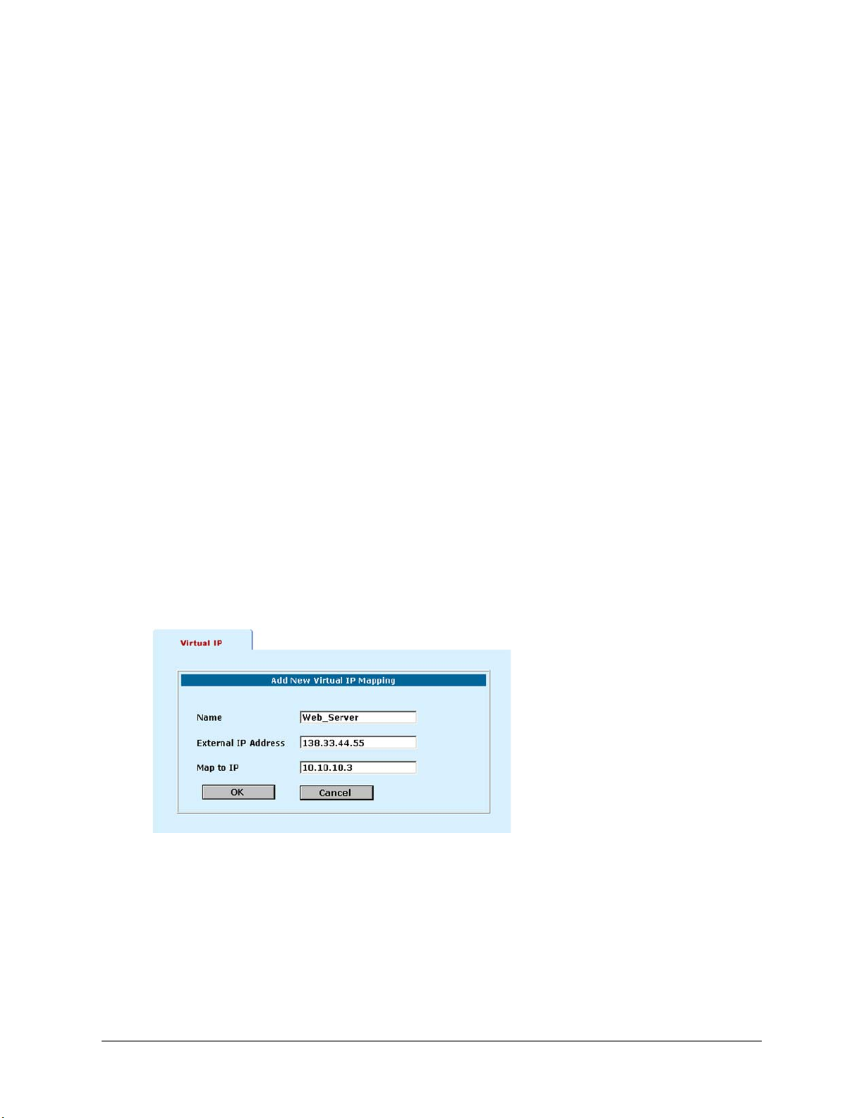
Polices that require authentication must be added to the policy list above matching policies that do
not, otherwise the policy that does not require authentication is selected first.
Virtual IPs
Running the DFL-1000 in NAT mode hides the actual addresses of the computers on your internal and
DMZ networks from the Internet. To provide Internet access to a server on your DMZ or internal network,
you must make an association between the Internet address of the server and the actual IP address of
the computer on the DMZ or internal network that is running the server. This association is called a Virtual
IP.
Once you have created a Virtual IP, you can add Incoming policies to allow access to the server by
adding the virtual IP to the Destination address of the policy.
Adding Virtual IPs
To add a Virtual IP:
• Go to Firewall > Virtual IP .
• Click New to add Virtual IP.
• Enter a Name for the Virtual IP.
• In the External IP Address field, enter the Internet IP address of the server.
This must be a static IP address obtained from your ISP for this purpose and must not be the same
as the external address of the DFL-1000. However, your ISP must route this address to the external
IP address of the DFL-1000.
• In the Map to IP field, enter the actual IP address of the web server on your DMZ or internal network.
• Click OK to save the Virtual IP.
• Repeat these steps to add Virtual IPs for all of your internet servers.
Adding a Virtual IP:
IP/MAC binding
IP/MAC binding provides added security against IP Spoofing attacks. IP Spoofing attempts to use the IP
address of a trusted computer to access the DFL-1000 from a different computer. The IP address of a
computer can easily be changed to a trusted address, but MAC addresses are added to ethernet cards at
the factory and cannot easily be changed.
You can enter the IP addresses and corresponding MAC addresses of trusted computers into the DFL1000 firewall configuration. When a data packet arrives from a trusted IP address, it is checked to
DFL-1000 User’s Manual
44
Page 45

determine whether the MAC address that the packet originated from matches the MAC address in the
table. The DFL-1000 checks all packets arriving at the DFL-1000 whether they are directed at the DFL1000 or are meant to be passed through.
MAC addresses are only carried on the local network where they originate, and are not passed from one
network to another.
This section describes:
• Adding IP/MAC binding addresses
• Enabling IP/MAC binding
Adding IP/MAC binding addresses
• Go to Firewall > IP/MAC Binding > IP MAC .
• Click New to add an IP address/MAC address pair.
• Click Enable to activate the IP/MAC binding pair.
Enabling IP/MAC binding
• Go to Firewall > IP/MAC Binding > Setting .
• Click Enable IP/MAC.
• Select one of the following:
Allow traffic when
not defined in the
table
Deny traffic when
not defined in the
table
The DFL-1000 lets traffic with a source address not found in the IP/MAC binding table
pass through the firewall. Any traffic with a source address that is defined in the IP/MAC
binding table must have the correct MAC address or it is blocked.
The DFL-1000 blocks all traffic with a source address that is not found in the IP/MAC
binding table. Any traffic with a source address that is defined in the IP/MAC binding
table must have the correct MAC address or it is also blocked.
• Click Apply to save your changes.
Traffic shaping
Traffic Shaping makes it possible to control which policies have the highest priority when large amounts
of data are moving through the DFL-1000. For example, the policy for the corporate web server might be
given higher priority than the policies for most employees' computers. An employee who needs unusually
high speed Internet access could have a special outgoing policy set up with higher bandwidth.
You can use traffic shaping to guarantee the amount of bandwidth available through the firewall for a
policy. Guarantee bandwidth to make sure that there is enough bandwidth available for a hi-priority
service.
You can also use traffic shaping to limit the amount of bandwidth available through the firewall for a policy.
Limit bandwidth to keep less important services from using bandwidth needed for more important services.
Adding traffic shaping to a policy
You can add traffic shaping to any type of policy. The following procedure describes adding traffic
shaping to an Int to Ext policy.
• Go to Firewall > Policy > Int to Ext .
• Choose a policy to add traffic shaping to and click Edit
• Turn on traffic shaping.
• Configure traffic shaping for the policy:
.
DFL-1000 User’s Manual
45
Page 46

Guaranteed bandwidth
Maximum bandwidth
Traffic Priority
Available in a future release.
Available in a future release.
Select high, medium, or low.
• Click OK to save your changes to the policy.
VPN pass through
Configure IPSec and PPTP pass through so that users on your internal network can connect to a VPN on
the Internet. VPN pass through allows the VPN connection to pass-through your firewall and connect to
the destination VPN. The DFL-1000 performs address translation on the connection, so that it seems to
the target VPN gateway that the connection to its VPN is originating from the external interface of your
DFL-1000.
Use VPN pass through so that:
• A visitor using your internal network can connect to their organization's VPN
• A subnet on your Internal network, protected by a VPN gateway, can use VPN to connect to a VPN
on the Internet
DFL-1000 VPN pass through can be configured for IPSec or PPTP VPN connections.
No special VPN configuration is required for the client or VPN gateway on your internal network. The VPN
tunnel configuration of the VPN gateway on the Internet must be changed to accept connections from the
IP address of the external interface of the DFL-1000.
Adding IPSec and PPTP pass through
To configure IPSec and PPTP pass through:
• Go to Firewall > Policy .
• Select IPSEC Pass Through to allow IPSec VPN connections from your internal network to IPSec
VPNs on the Internet.
• Select PPTP Pass Through to allow PPTP VPN connections from your internal network to PPTP and
L2TP VPNs on the Internet.
• Click Apply.
DFL-1000 User’s Manual
46
Page 47

IPSec VPNs
Using DFL-1000 IPSec Virtual Private Networking (VPN), you can join two or more widely separated
private networks together through the Internet. For example, a company that has two offices in different
cities, each with its own private network, can use VPN to create a secure tunnel between the offices. In
addition, remote or travelling workers can use a VPN client to create a secure tunnel between their
computer and their office private network.
The secure IPSec VPN tunnel makes it appear to all computer users that they are on physically
connected networks. The VPN protects data passing through the tunnel by encrypting it to guarantee
confidentiality. In addition, authentication guarantees that the data originated from the claimed sender and
was not damaged or altered in transit.
IPSec is an internet security standard for VPN and supported by most VPN products. DFL-1000 IPSec
VPNs can be configured to use Autokey Internet Key Exchange (IKE) or manual key exchange. Autokey
key exchange is easier to configure and maintain than manual key exchange. However, manual key
exchange is available for compatibility with third party VPN products that require it.
IPSec VPN is only supported in NAT mode.
This chapter describes:
• Compatibility with third-party VPN products
Autokey IPSec VPN between two networks
•
Autokey IPSec VPN for remote clients
•
Manual key exchange IPSec VPN between two networks
•
Manual key exchange IPSec VPN for remote clients
•
Testing a VPN
•
Compatibility with third-party VPN products
Because the DFL-1000 supports the IPSec industry standard for VPN, you can configure a VPN between
the DFL-1000 and any third party VPN client or gateway/firewall that supports IPSec VPN. To
successfully establish the tunnel, the VPN settings must be the same on the DFL-1000 and the third party
product.
DFL-1000 IPSec VPNs support:
• IPSec Internet Protocol Security standard
• Automatic IKE based on Pre-shared Key
• Fully customizable manual keys
• ESP security in tunnel mode
• 3DES (TripleDES) encryption
• HMAC MD5 authentication/data integrity or HMAC SHA authentication/data integrity
Autokey IPSec VPN between two networks
Use the following procedures to configure a VPN that provides a direct communication link between users
and computers on two different networks. Example VPN between two internal networks shows an
example VPN between the main office and a branch office of a company. Users on the main office
DFL-1000 User’s Manual
47
Page 48
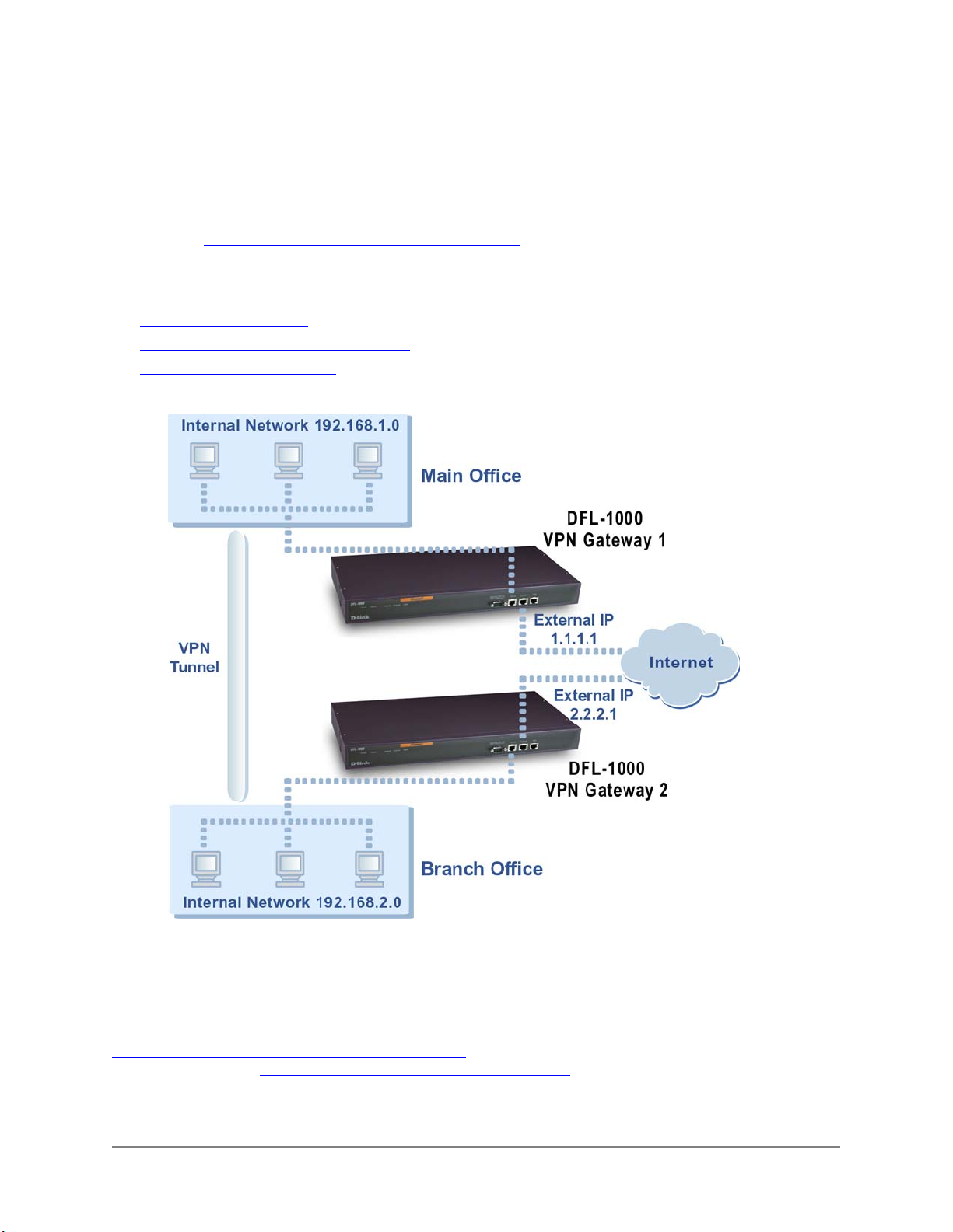
internal network can connect to the branch office internal network and users on the branch office internal
network can connect to the main office internal network. Users on the branch office network can also
connect to services such as an email server running on the main network.
Communication between the two networks takes place in an encrypted VPN tunnel that connects the two
DFL-1000 VPN gateways across the Internet. Users on the internal networks are not aware that when
they connect to a computer on the other network that the connection is across the Internet.
As shown in Example VPN between two internal networks
, each internal network can be protected by a
DFL-1000 VPN gateway. Alternatively, one of the networks can be protected by a third-party VPN
gateway that also supports IPSec and Autokey IKE.
Use the following procedures to configure an IPSec Autokey IKE VPN between internal networks:
Creating the VPN tunnel
•
Adding internal and external addresses
•
Adding an IPSec VPN policy
•
Figure: Example VPN between two internal networks:
Creating the VPN tunnel
A VPN tunnel consists of a name for the tunnel, the IP address of the VPN gateway at the opposite end of
the tunnel, the keylife for the tunnel, and the authentication key to be used to start the tunnel. You must
create complementary VPN tunnels on each of the VPN gateways. On both gateways the tunnel should
have the same name, keylife, and authentication key.
Example IPSec Autokey VPN Tunnel configuration
tunnel for the VPN in Example VPN between two internal networks.
DFL-1000 User’s Manual
shows the information required to configure the VPN
48
Page 49
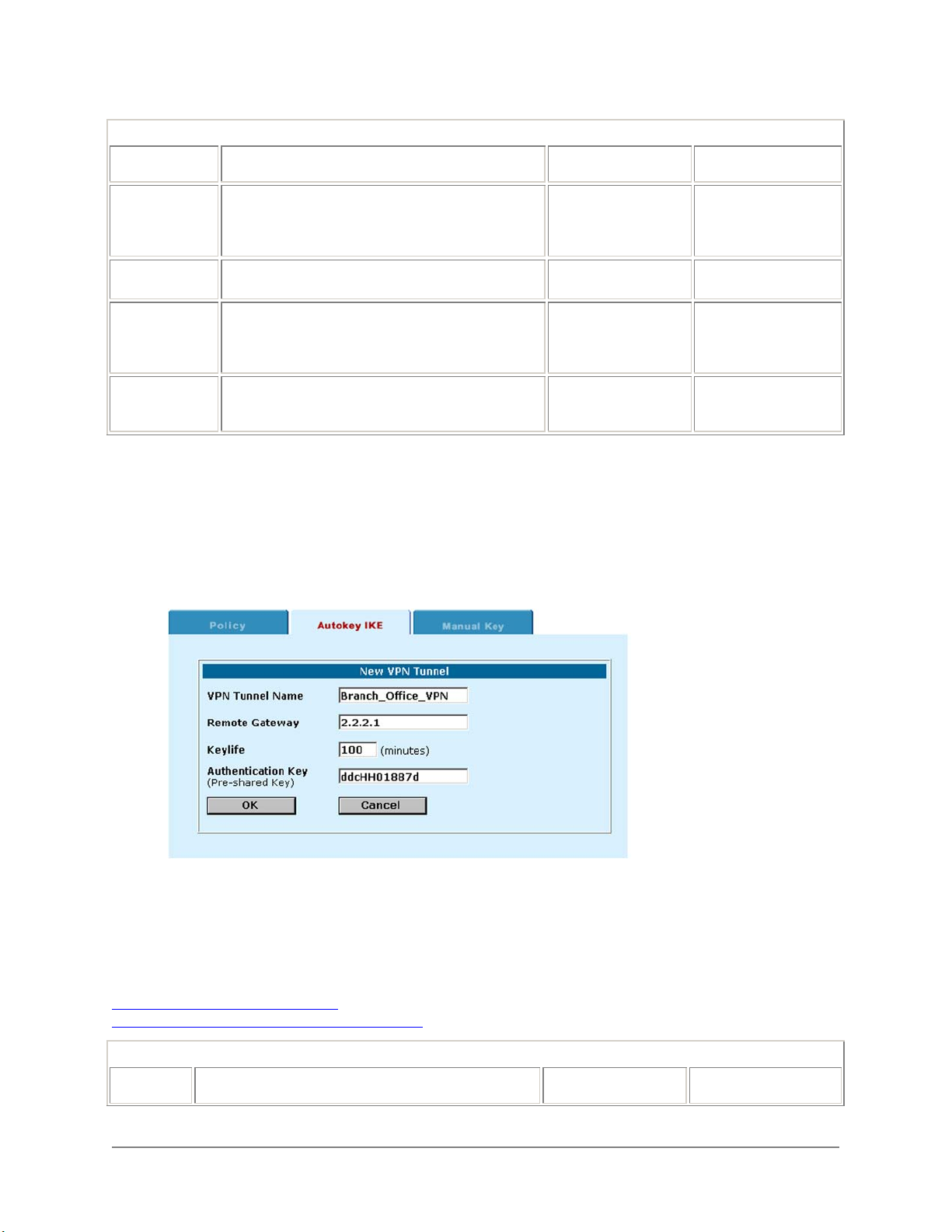
Example IPSec Autokey VPN Tunnel configuration
Description
VPN Tunnel
Name
Remote
Gateway
Keylife
Authentication
Key
Use the same name on both ends of the tunnel.
The name can contain alphabetic characters,
numbers and the special characters - and _.
Spaces and the @ character are not allowed.
The External IP address of the VPN gateway at the
other end of the VPN tunnel.
The amount of time (5 to 1440 minutes) before the
encryption key expires. When the key
expires, the VPN gateways generate a new
key without interrupting service.
Enter up to 20 characters. The key must be the
same on both VPN gateways and should
only be known by network administrators.
Main Office (VPN
Gateway 1)
Branch_Office_VPN Branch_Office_VPN
2.2.2.1 1.1.1.1
100 100
ddcHH01887d ddcHH01887d
Branch Office (VPN
Gateway 2)
Complete the following procedure on both VPN gateways to configure a VPN tunnel that uses Autokey
IKE key exchange:
• Go to VPN > IPSEC > Autokey IKE .
• Click New to add a new Autokey IKE VPN tunnel.
• Enter the VPN Tunnel Name, Remote Gateway, Keylife and Authentication Key.
• Click OK to save the Autokey IKE VPN tunnel.
Example Main Office Autokey IKE VPN tunnel:
Adding internal and external addresses
The next step in configuring the VPN is to add the addresses of the networks that are to be connected
using the VPN tunnel. On each VPN gateway you must add two addresses:
• Internal address, the IP address of the network behind the VPN gateway
• External address, the IP address of the network behind the other VPN gateway
IPSec Autokey VPN addresses
Example VPN between two internal networks
IPSec Autokey VPN addresses
Description
shows the internal and external addresses required for the VPN in
. In the example, both IP addresses are for internal networks.
Main Office (VPN
Gateway 1)
Branch Office (VPN
Gateway 2)
DFL-1000 User’s Manual
49
Page 50
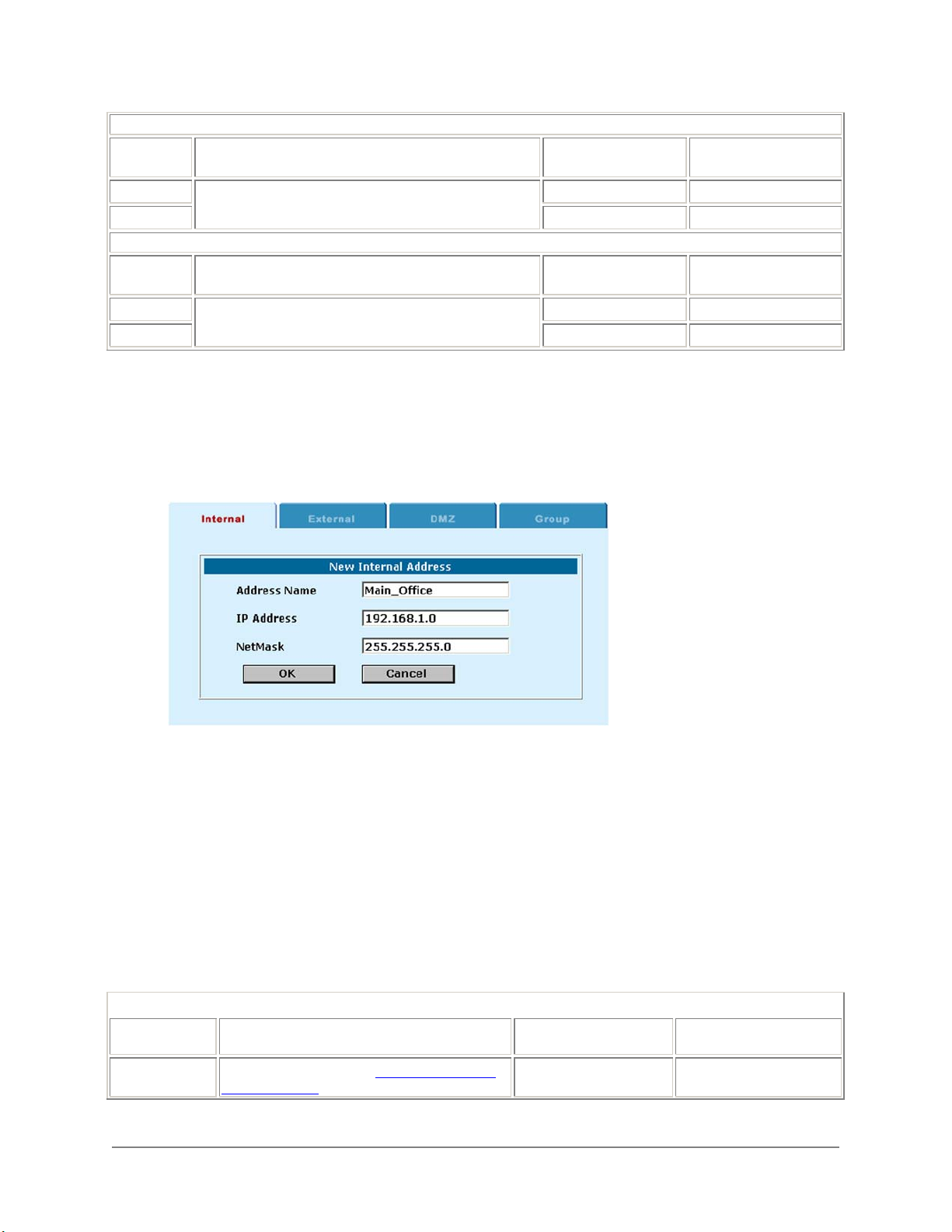
Internal Address
Address
Name
IP address
Netmask
External Address
Address
Name
IP address
Netmask
The name to assign to the internal network to be
connected using the VPN.
The IP address and netmask of the internal network.
The name to assign to the internal network to be
connected to the opposite end of the VPN tunnel.
The IP address and netmask of the internal network at
the other end of the VPN tunnel.
Main_Office Branch_Office
192.168.1.0 192.168.2.0
255.255.255.0 255.255.255.0
Branch_Office Main_Office
192.168.2.0 192.168.1.0
255.255.255.0 255.255.255.0
Complete the following procedure on both VPN gateways to add the internal and external IP addresses:
• Go to Firewall > Address > Internal .
• Click New to add a new internal address.
• Enter the Address Name and the IP Address and NetMask of the internal network that can connect to
the VPN.
Example internal address for VPN Gateway 1:
• Click OK to save the internal address.
• Go to Firewall > Address > External .
• Click New to add a new external address.
• Enter the Address Name and the IP Address and NetMask of the network behind the other VPN
gateway.
• Click OK to save the external address.
Adding an IPSec VPN policy
The VPN policy associates the source and destination addresses created in the previous procedure with
the VPN tunnel created in the first procedure. Each VPN gateway then receives all traffic from the internal
address that is destined for the external address and routes it across the Internet to the other VPN
gateway using the VPN tunnel.
Example IPSec Autokey VPN policy configuration
Description
Source IP
address
DFL-1000 User’s Manual
The Internal IP address (See IPSec Autokey
VPN addresses).
Main Office (VPN
Gateway 1)
Main_Office Branch_Office
Branch Office (VPN
Gateway 2)
50
Page 51
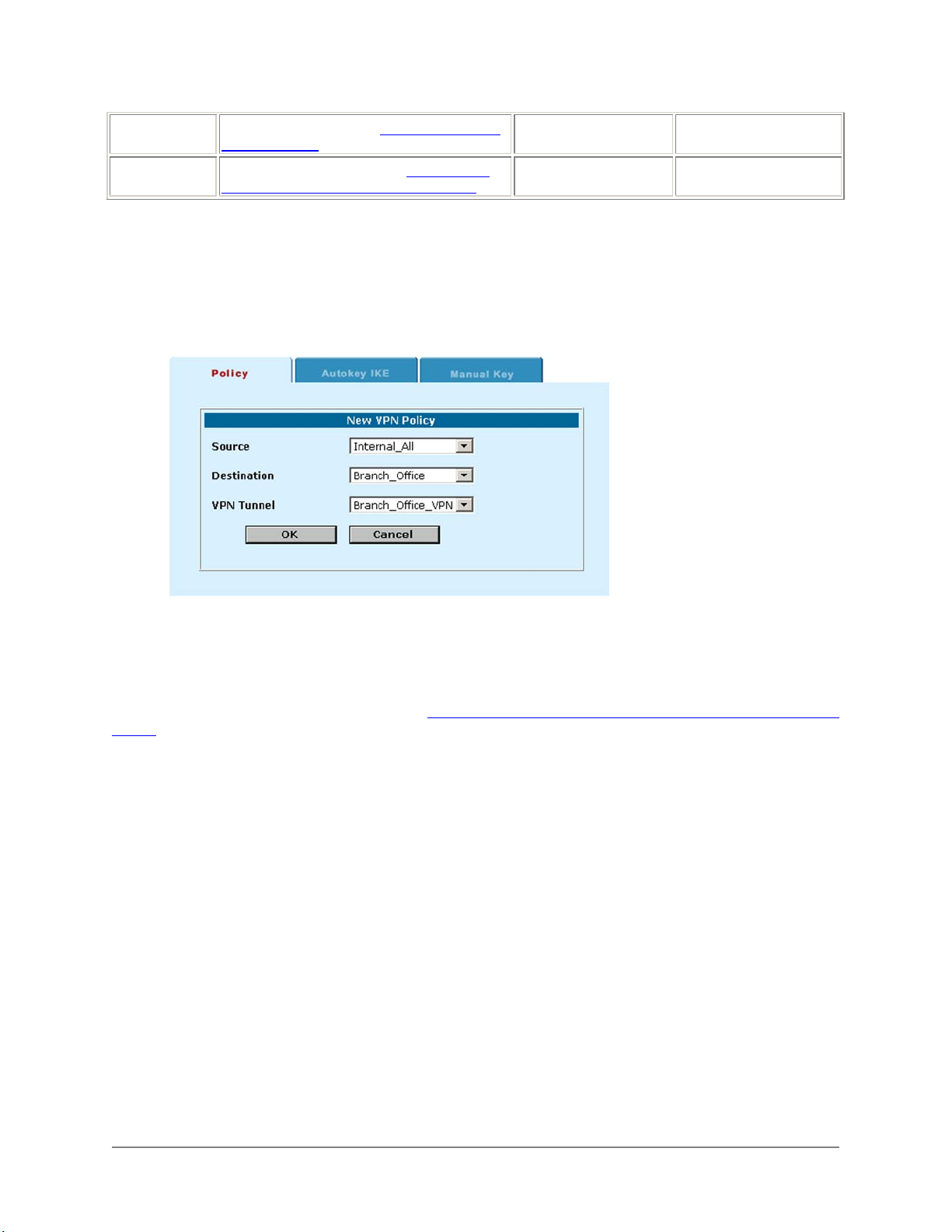
Destination IP
Address
VPN Tunnel
Name
The External IP address (See IPSec Autokey
VPN addresses).
The name of the VPN tunnel (See Example
IPSec Autokey VPN Tunnel configuration).
Branch_Office Main_Office
Branch_Office_VPN Branch_Office_VPN
Complete the following procedure on both VPN gateways to add the VPN policy:
• Go to VPN > IPSEC > Policy .
• Click New to add a new IPSec VPN policy.
• Configure the VPN Policy.
• Click OK to save the VPN policy.
Example Main Office VPN policy:
Autokey IPSec VPN for remote clients
Use the following procedures to configure a VPN that allows remote VPN clients to connect to users and
computers on a Main Office internal network (See Example VPN between an internal network and remote
clients). A remote VPN client can be any computer connected to the Internet and running VPN client
software that uses IPSec and Autokey IKE. The client can have a static IP address or a dynamic IP
address. A remote client could be:
• A traveller using a dial-up connection to connect to the Internet
• A telecommuter using an ISP to connect to the Internet from home
Communication between the remote users and the internal network takes place over an encrypted VPN
tunnel that connects the remote user to the DFL-1000 VPN gateway across the Internet. Once connected
to the VPN, the remote user's computer appears as if it is installed on the internal network.
DFL-1000 User’s Manual
51
Page 52
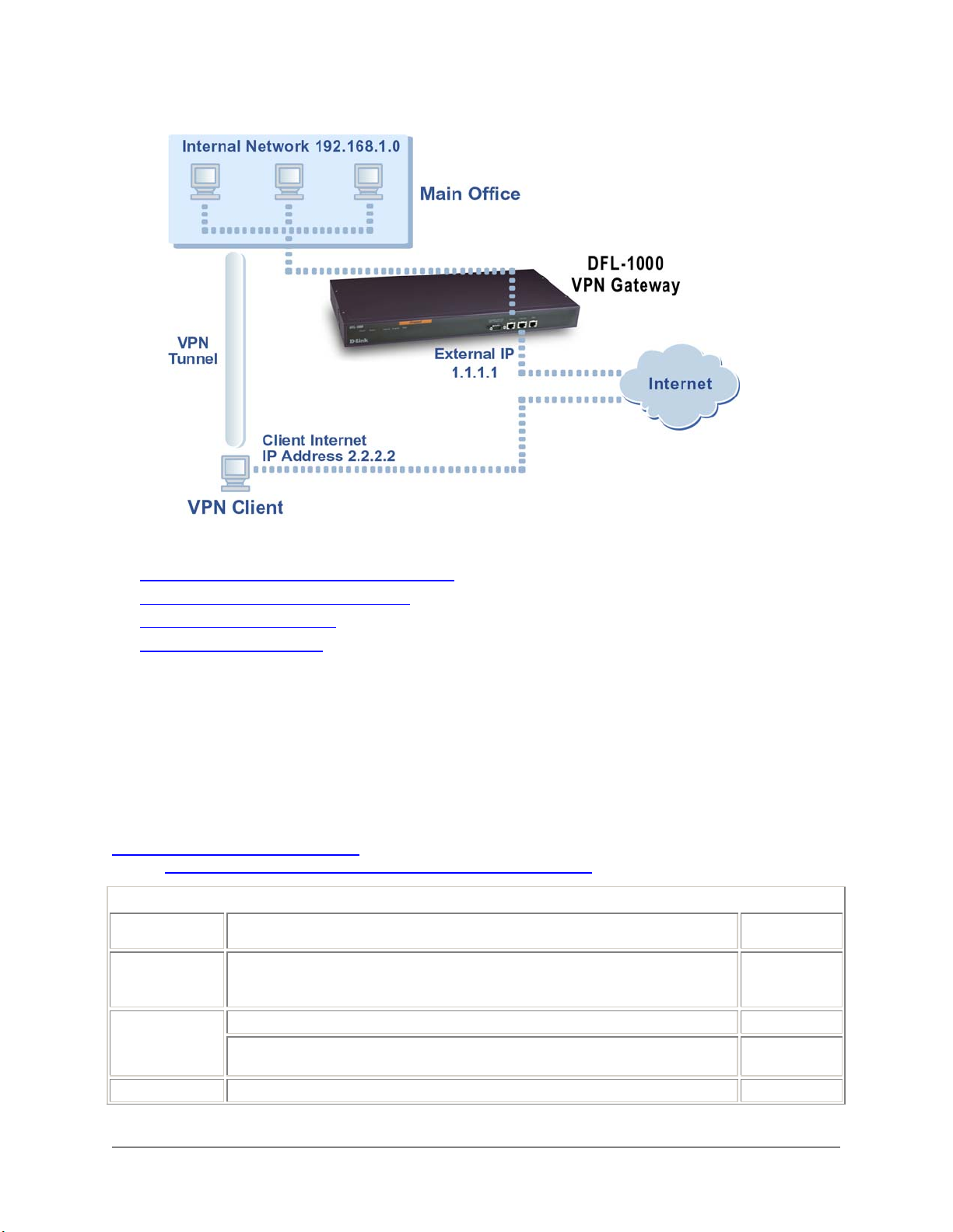
Example VPN between an internal network and remote clients:
Use the following procedures to configure an IPSec Autokey IKE VPN that allows VPN clients to connect
to an internal network:
• Configuring the VPN tunnel for the client VPN
Adding internal and external addresses
•
Adding an IPSec VPN policy
•
Configuring the VPN client
•
Configuring the VPN tunnel for the client VPN
A VPN tunnel consists of a name for the tunnel, the remote gateway IP address (which is the IP address
of the client), the keylife for the tunnel, and the authentication key to be used to start the tunnel.
You can either create multiple VPN tunnels, one for each VPN client, or you can create one VPN tunnel
with a remote gateway address set to 0.0.0.0. This VPN tunnel accepts connections from any Internet
address.
You must create complementary VPN tunnels on the VPN gateway and the clients. On both, the tunnel
must have the same name, keylife, and authentication key.
Example VPN Tunnel configuration
VPN in Example VPN between an internal network and remote clients
Example VPN Tunnel configuration
Description
VPN Tunnel
Name
Remote
Gateway
Keylife
Use the same name on both ends of the tunnel. The name can contain alphabetic
characters, numbers and the special characters - and _. Spaces and the @
character are not allowed.
To accept connections from a client at a static IP address (for example, 2.2.2.2). 2.2.2.2
To accept connections from any Internet address (for a client with a dynamic IP
address).
shows the information required to configure the VPN tunnel for the
.
Example
Setting
Client_VPN
0.0.0.0
100
DFL-1000 User’s Manual
52
Page 53
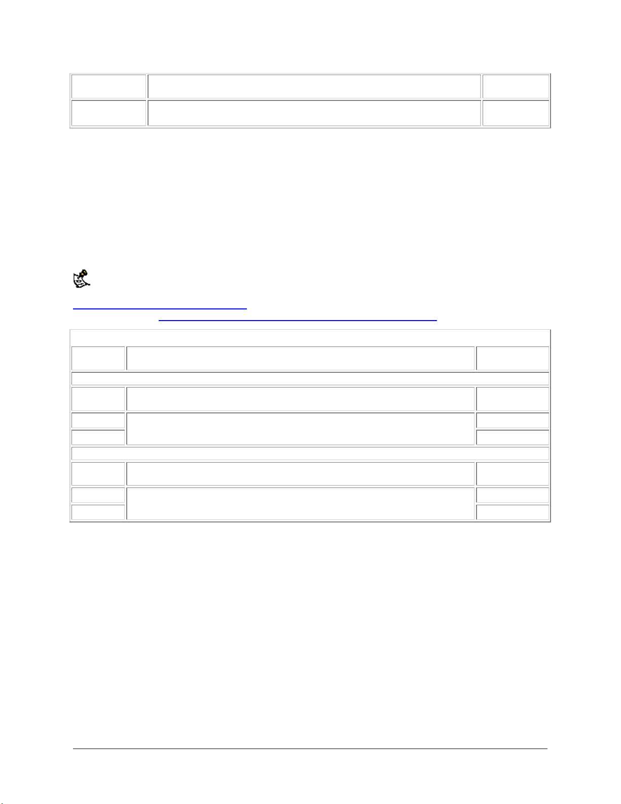
the key expires, the VPN gateway and the client generate a new key without
interrupting service.
Authentication
Key
Enter up to 20 characters. The VPN gateway and clients must have the same
key.
ddcHH01887d
Complete the following procedure on the DFL-1000 VPN gateway.
• Go to VPN > IPSEC > Autokey IKE .
• Click New to add a new Autokey IKE VPN tunnel.
• Enter the VPN Tunnel Name, Remote Gateway, Keylife, and Authentication Key.
• Click OK to save the Autokey IKE VPN tunnel.
Adding internal and external addresses
The next step in configuring the VPN is to add the addresses of the VPN clients as well as the address of
the internal to the VPN gateway.
You do not have to add addresses for remote clients with dynamic IP addresses.
Example VPN Gateway IP Addresses shows the internal and external addresses required for the VPN
Gateway shown in Example VPN between an internal network and remote clients
Example VPN Gateway IP Addresses
Description
Internal Address
Address
Name
IP address
Netmask
External Address
Address
Name
IP address
Netmask
The name to assign to the internal network that the VPN client can connect to. Main_Office
The IP address and netmask of the internal network that the VPN client can connect
to.
The name to assign to the VPN client. VPN_Client
The IP address and netmask of a VPN client with a static IP address (for example,
2.2.2.2). You do not have to add an address for a client with a dynamic IP address.
.
Example
Setting
192.168.1.0
255.255.255.0
2.2.2.2
255.255.255.255
Complete the following procedure on the VPN gateway to add the internal and external IP addresses:
• Go to Firewall > Address > Internal .
• Click New to add a new internal address.
• Enter an Address Name, IP Address and NetMask for the internal network.
• Click OK to save the internal address.
• Go to Firewall > Address > External .
• Click New to add the static IP address of the client.
• Enter an Address Name, IP Address, and NetMask for the VPN client.
• Click OK to save the client address.
Adding an IPSec VPN policy
The VPN policy associates the source address of the internal network and the destination address of the
VPN client with the VPN tunnel created for the VPN client. The VPN gateway then starts up the VPN
tunnel whenever it receives packets from the VPN client. Once the VPN tunnel is established, all traffic
DFL-1000 User’s Manual
53
Page 54
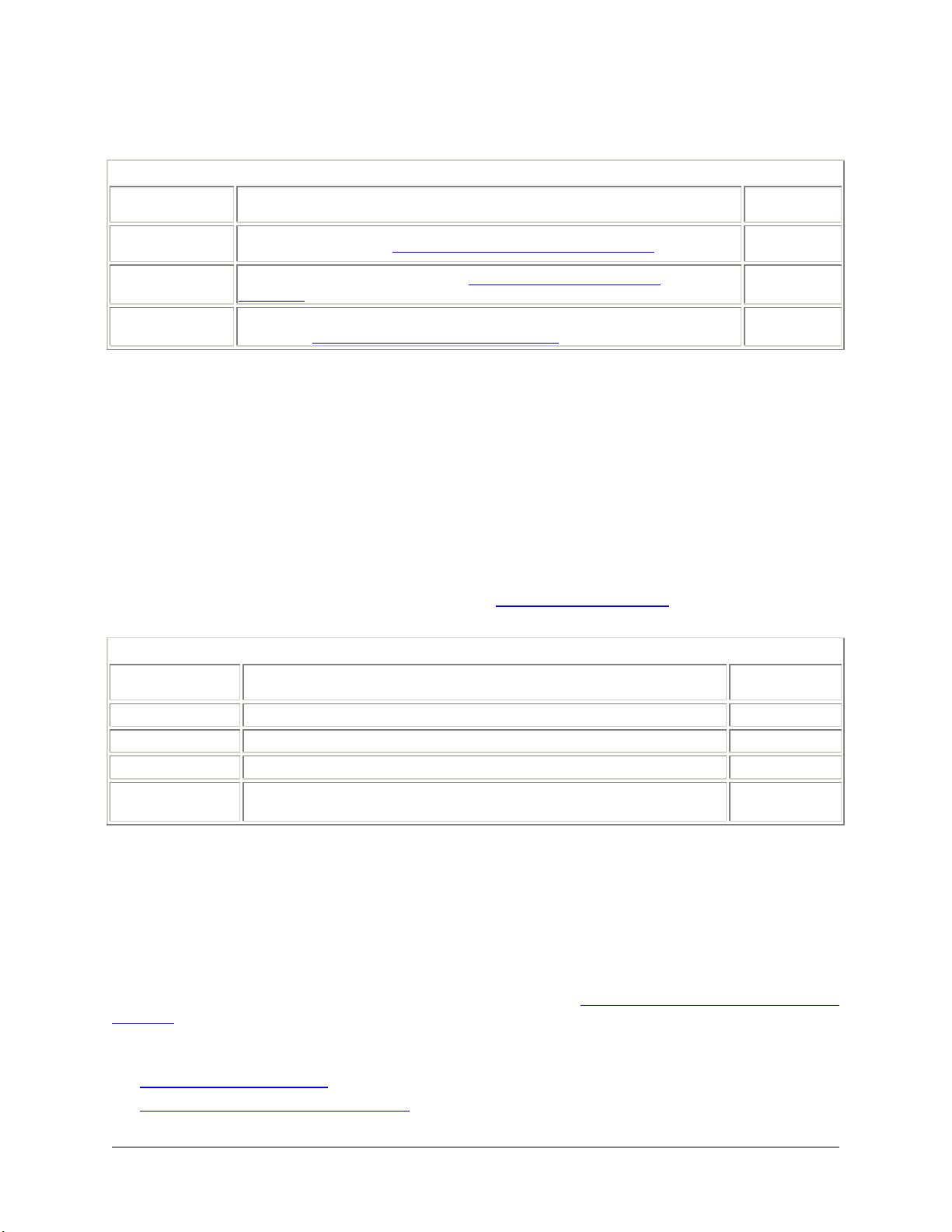
between the VPN client and the VPN gateway that is destined for the internal network is routed across
the Internet in the VPN tunnel.
Example VPN Gateway policy configuration
Description
Source IP
address
Destination IP
Address
VPN Tunnel
Name
The Internal IP address (See Example VPN Gateway IP Addresses
The Internet IP address of the client (See Example VPN Gateway IP
Addresses).
The name of the VPN tunnel to be created between the VPN gateway and the
VPN client (See Example VPN Tunnel configuration
). Main_Office
).
Example
setting
VPN_Client
Client_VPN
Complete the following procedure on the VPN gateway to add the VPN policy:
• Go to VPN > IPSEC > Policy .
• Click New to add a new IPSec VPN policy.
• Select the Source IP address, Destination IP address, and the VPN tunnel to add to the IPSec VPN
policy.
• Click OK to save the VPN policy.
Configuring the VPN client
The VPN client PC must be running industry standard IPSec Autokey IKE VPN client software. D-Link
recommends the SafeNet/Soft-PK client from IRE, Inc.
Configure the client as required to connect to the VPN gateway using an IPSec VPN configuration. Make
sure the client configuration includes the settings in VPN client configuration
match the VPN Gateway configuration.
VPN client configuration
Description
VPN Tunnel Name
Remote Gateway
Keylife
Authentication
Key
Should correspond to the VPN tunnel name used on the VPN gateway. Client_VPN
The External IP address of the VPN gateway. 1.1.1.1
The Client key life should match the VPN gateway key life. 100
The Client authentication key should match the VPN gateway authentication
key.
. These settings should
Example
Setting
ddcHH01887d
Manual key exchange IPSec VPN between two networks
DFL-1000 IPSec VPNs can be configured to use Autokey IKE and manual key exchange. In most cases
the Autokey key exchange is preferred because it is easier to configure and maintain. However, manual
key exchange may be necessary in some cases for compatibility with third party VPN products.
Use the following procedures to configure a VPN between two internal networks protected by VPN
gateways that use manual key exchange (for an example, see Example VPN between two internal
networks). Each internal network can be protected by a DFL-1000 VPN gateway or one of the networks
can be protected by a third-party VPN gateway.
This section describes:
• Configuring the VPN tunnel
• Adding internal and external addresses
DFL-1000 User’s Manual
54
Page 55
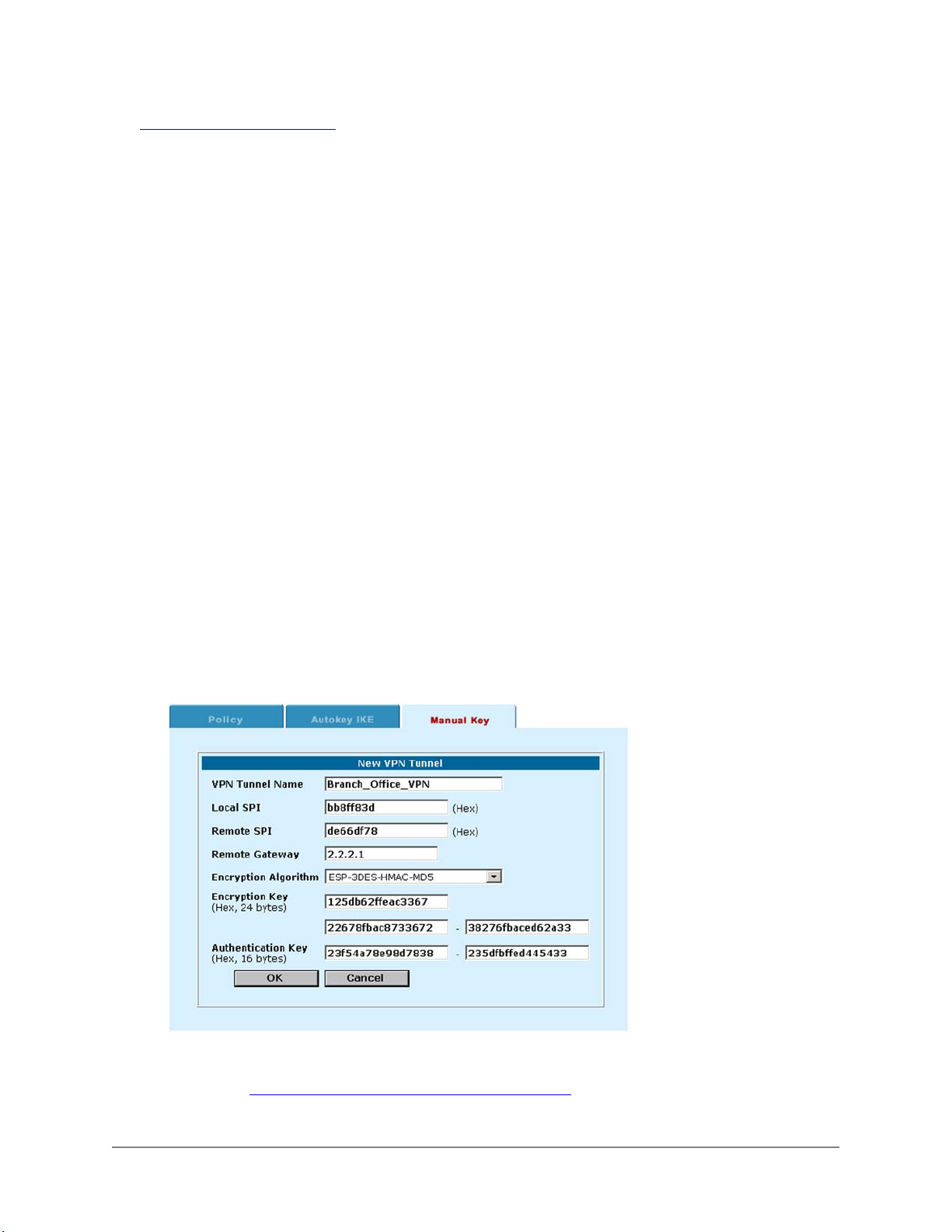
• Adding an IPSec VPN policy
Configuring the VPN tunnel
Complete the following procedure on both VPN gateways.
• Go to VPN > IPSEC > Manual Key .
• Click New to add a new manual key VPN tunnel.
• Configure the VPN tunnel.
VPN Tunnel
Name
Local SPI
Remote SPI
Remote
Gateway
Encryption
Algorithm
Encryption Key
Authentication
Key
Enter a name for the tunnel. The name can contain alphabetic characters, numbers and some
special characters like - and _. Spaces and the @ character are not allowed. If you are configuring
a VPN between two DFL-1000 gateways, it is recommended that you use the same tunnel name
on both sides of the VPN.
(Secure Parameter Index) Enter a hexadecimal number of up to eight digit (digits can be 0 to 9, a
to f). This number must be added to the Remote SPI at the opposite end of the tunnel.
Enter a hexadecimal number of up to eight digits (digits can be 0 to 9, a to f). This number must be
added to the Local SPI at the opposite end of the tunnel.
Enter the external IP address of the DFL-1000 or other IPSec gateway at the opposite end of the
tunnel.
Select one of the three algorithms (3DES, 3DES/MD5, or 3DES/SHA1) Use the same algorithm at
both ends of the tunnel.
Enter three hexadecimal numbers of up to 16 digits each (digits can be 0 to 9, a to f). Use the
same encryption key at both ends of the tunnel.
Enter an authentication key. If you selected 3DES/MD5 for the Encryption Algorithm, enter two
hexadecimal numbers of 16 digits each. If you selected 3DES/SHA1 for the Encryption Algorithm,
enter two hexadecimal numbers, one of 16 digits and one of 14 digits. Use the same
authentication key at both ends of the tunnel.
• Click OK to save the manual key VPN tunnel.
Example manual key exchange VPN tunnel:
Adding internal and external addresses
Use the procedure “See Adding internal and external addresses” to configure the internal and external
addresses used by the VPN policy.
DFL-1000 User’s Manual
55
Page 56

Adding an IPSec VPN policy
Use the procedure See Adding an IPSec VPN policy to configure the outgoing policy that connects from
the local internal network through the VPN tunnel to the remote internal network.
Manual key exchange IPSec VPN for remote clients
Use the following procedures to configure a VPN that allows remote clients to connect to computers on a
Main Office internal network (See Example VPN between an internal network and remote clients). A
remote VPN client can be any computer connected to the Internet and running VPN client software that
uses IPSec and manual key exchange. The client must have a static IP address.
Communication between the remote users and the internal network takes place over an encrypted VPN
tunnel that connects the remote user to the DFL-1000 VPN gateway across the Internet. Once connected
to the VPN, the remote user's computer appears as if it is installed on the internal network.
Manual key exchange VPNs do not support VPN clients with dynamic IP addresses.
The VPN client PC must have industry standard VPN client software installed. DFL-1000 VPN is based
on the industry standard IPSec implementation of VPN making it interoperable with other IPSec VPN
products (see Compatibility with third-party VPN products). D-Link recommends SafeNet/Soft-PK from
IRE, Inc.
Configuring the VPN tunnel
You can either create multiple VPN tunnels, one for each VPN client, or you can create one VPN tunnel
with a remote gateway address set to 0.0.0.0. This VPN tunnel accepts connections from any Internet
address.
You must create complementary VPN tunnels on the VPN gateway and the clients. On both, the tunnel
must have the same name, keylife, and authentication key.
Complete the following procedure on the DFL-1000 VPN gateway.
• Go to VPN > IPSEC > Manual Key .
• Click New to add a new manual key VPN tunnel.
• Configure the VPN tunnel as described in Configuring the VPN tunnel
• In the Remote Gateway field, enter the external IP address of the VPN client.
For the example network shown in Example VPN between an internal network and remote clients
you would use 2.2.2.2 as the remote gateway. To accept connections from more than one client, set
the Remote Gateway address to 0.0.0.0.
• Click OK to save the manual key VPN tunnel.
.
,
Adding internal and external addresses
Use the procedure See Adding internal and external addresses to configure the internal and external
addresses used by the VPN policy.
Adding an IPSec VPN policy
Use the procedure See Adding an IPSec VPN policy to add a VPN policy that associates the source
address of the internal network and the destination address of the VPN client with the VPN tunnel created
for the VPN client.
DFL-1000 User’s Manual
56
Page 57

Testing a VPN
To confirm that a VPN between two networks has been configured correctly, use the ping command from
one internal network to connect to a computer on the other internal network. The IPSec VPN tunnel starts
automatically when the first data packet destined for the VPN is intercepted by the DFL-1000.
To confirm that a VPN between a network and one or more clients has been configured correctly, start a
VPN client and use the ping command to connect to a computer on the internal network. The VPN tunnel
initializes automatically when the client makes a connection attempt. You can start the tunnel and test it at
the same time by pinging from the client to an address on the internal network.
DFL-1000 User’s Manual
57
Page 58

PPTP and L2TP VPNs
Using DFL-1000 PPTP and L2TP Virtual Private Networking (VPN), you can create a secure connection
between a client computer running Windows and an internal network protected by a DFL-1000.
PPTP is a Microsoft Windows VPN standard. You can use PPTP to connect computers running Microsoft
Windows to a DFL-1000-protected private network without using third party VPN client software.
L2TP combines Windows PPTP functionality with IPSec security. L2TP is supported by most recent
versions of MS-Windows.
The secure VPN tunnel makes it appear to the user that the client computer is directly connected to the
internal network. The VPN protects data passing through the tunnel by encrypting it to guarantee
confidentiality. In addition, authentication guarantees that the data originated from the claimed sender and
was not damaged or altered in transit.
PPTP and L2TP VPNs are only supported in NAT mode.
This chapter describes:
• PPTP VPN configuration
• L2TP VPN configuration
• RADIUS authentication for PPTP and L2TP VPNs
PPTP VPN configuration
This section describes how to configure the DFL-1000 as a PPTP VPN server. This section also
describes how to configure Windows 98, Windows 2000, and Windows XP clients to connect to the PPTP
VPN.
You configure the DFL-1000 to support PPTP by adding PPTP users and specifying a PPTP address
range. You can also require PPTP VPN users to authenticate to your RADIUS server. Finally, to connect
to the PPTP VPN your remote Windows clients must be configured for PPTP.
DFL-1000 User’s Manual
58
Page 59
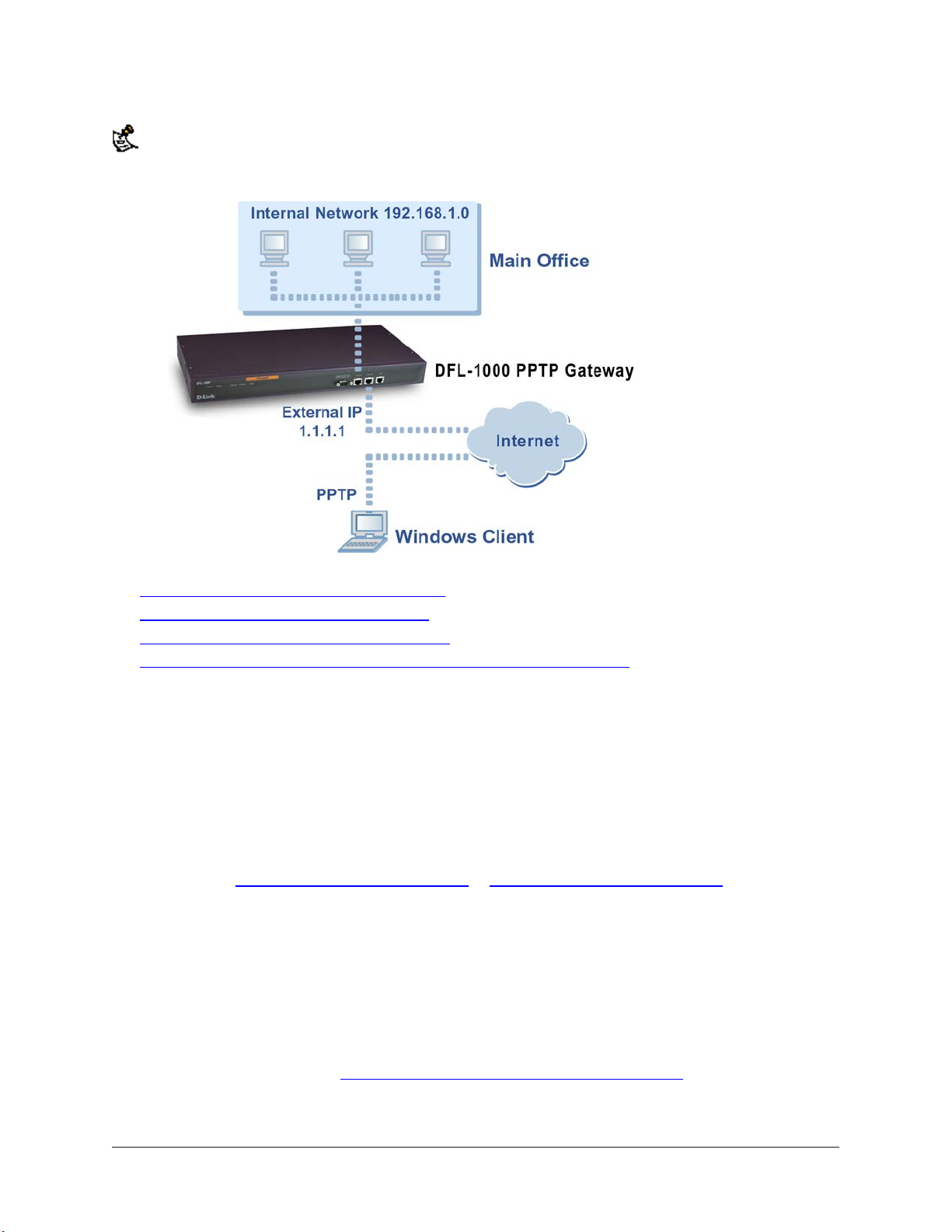
Make sure that your ISP supports PPTP connections.
PPTP VPN between a Windows client and the DFL-1000:
This section describes:
• Configuring the DFL-1000 as a PPTP server
• Configuring a Windows 98 client for PPTP
• Configuring a Windows 2000 Client for PPTP
• Configuring a Windows XP Client to connect to a DFL-1000 PPTP VPN
Configuring the DFL-1000 as a PPTP server
Use the following procedure to configure the DFL-1000 to be a PPTP server.
• Go to VPN > PPTP > PPTP User .
• Click New to add a PPTP user.
• Enter a user name and password.
The password must be at least 6 characters long and may contain numbers (0-9) and upper and
lower case letters (A-Z, a-z) but no spaces.
A client can connect to the PPTP VPN with this user name and password.
• Repeat steps Go to VPN > PPTP > PPTP User.
PPTP user names and passwords as required.
• Go to VPN > PPTP > PPTP Range .
• Click Enable PPTP.
• Specify the PPTP address range.
The PPTP address range is the range of addresses on your internal network that must be reserved
for remote PPTP clients. When a remote client connects to the internal network using PPTP, the
computer is assigned an IP address from this range.
• If you are planning on using RADIUS for authentication, click Enable RADIUS.
To turn on RADIUS support, see RADIUS authentication for PPTP and L2TP VPNs
• Click Apply to enable PPTP through the DFL-1000.
to Enter a user name and password. to add more
.
DFL-1000 User’s Manual
59
Page 60
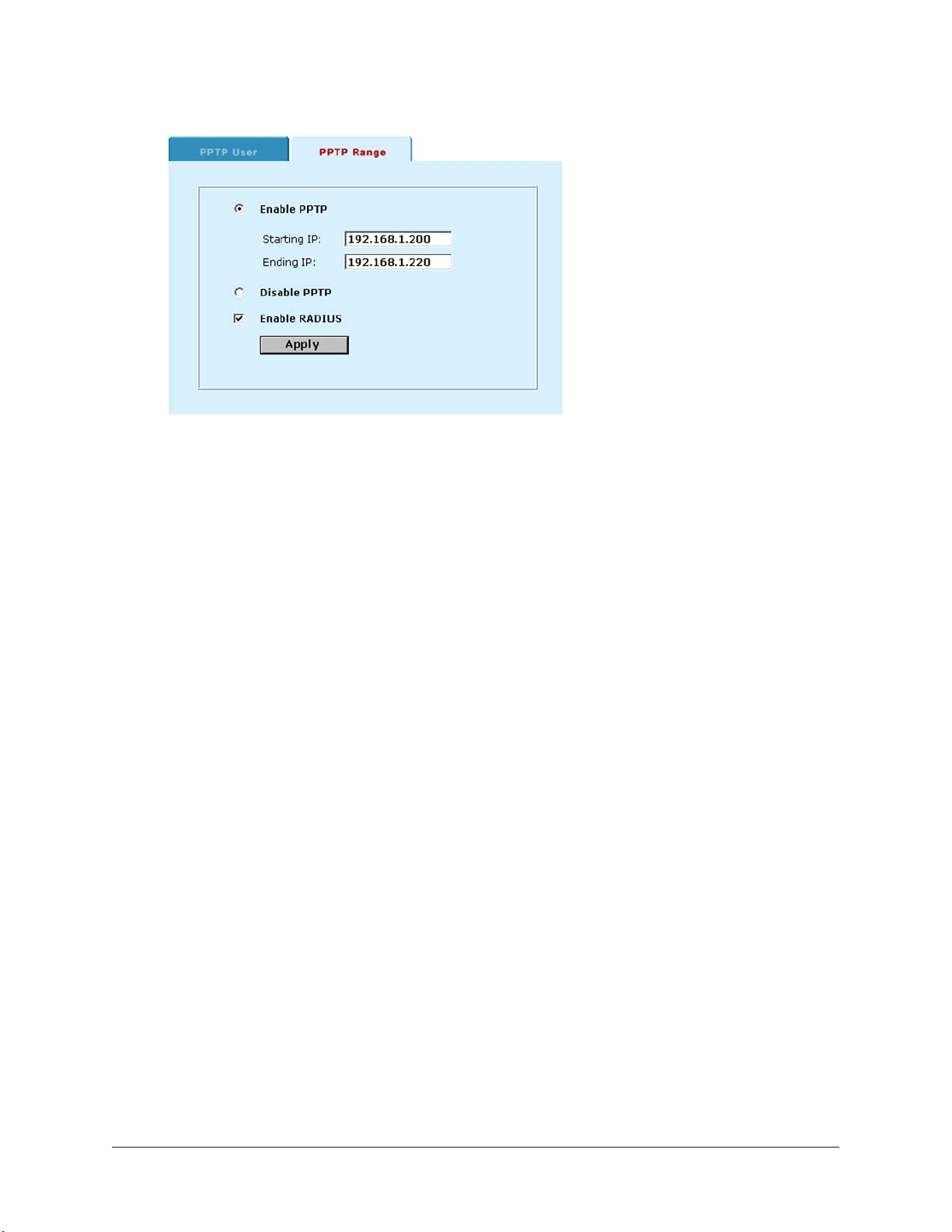
Sample PPTP Range configuration:
Configuring a Windows 98 client for PPTP
Use the following procedure to configure a client machine running Windows 98 so that it can connect to a
DFL-1000 PPTP VPN. To configure the Windows 98 client, you must install and configure windows dialup networking and virtual private networking support.
Installing PPTP support
• Go to Start > Settings > Control Panel > Network .
• Click Add.
• Choose Adapter.
• Click Add.
• Select Microsoft as the manufacturer.
• Select Microsoft Virtual Private Networking Adapter.
• Click OK twice.
• Insert diskettes or CDs as required.
• Restart the computer.
Configuring a PPTP dial-up connection
• Go to My Computer > Dial Up Networking .
• Double-click Make New Connection.
• Name the connection and click Next.
• Enter the external IP address or hostname of the DFL-1000 to connect to and click Next.
• Click Finish.
An icon for the new connection appears in the Dial-up networking folder.
• Right click the new icon and select Properties.
• Go to Server Types.
• Uncheck IPX/SPX Compatible.
• Click on TCP/IP Settings.
• Turn off Use IP header compression.
• Turn off Use default gateway on remote network.
DFL-1000 User’s Manual
60
Page 61

• Click OK twice.
Connecting to the PPTP VPN
• Start the dial-up connection that you configured in the previous procedure.
• Enter your PPTP VPN User Name and Password.
• Click Connect.
Configuring a Windows 2000 Client for PPTP
Use the following procedure to configure a client machine running Windows 2000 so that it can connect to
a DFL-1000 PPTP VPN.
Configuring a PPTP dial-up connection
• Go to Start > Settings > Network and Dial-up Connections .
• Double click Make New Connection to start the Network Connection Wizard. Click Next.
• For Network Connection Type, select Connect to a private network through the Internet and click Next.
• For Destination Address, enter the external address of the DFL-1000 to connect to and click Next.
• Set Connection Availability to Only for myself and click Next.
• Click Finish.
• Click Properties in the Connect window.
• Click the Security tab.
• Uncheck Require data encryption.
• Click OK.
Connecting to the PPTP VPN
• Start the dial-up connection that you configured in the previous procedure.
• Enter your PPTP VPN User Name and Password.
• Click Connect.
• In the connect window, enter the User Name and Password you use to connect to your dial-up
network connection.
This user name and password is not the same as your VPN user name and password.
Configuring a Windows XP Client to connect to a DFL-1000 PPTP VPN
Use the following procedure to configure a client machine running Windows XP so that it can connect to a
DFL-1000 PPTP VPN.
Configuring a PPTP dial-up connection
• Go to Start > Control Panel .
• Click Network and Internet Connections.
• Select Create a Connection to the network of your workplace and click Next.
• Click Virtual Private Network Connection and click Next.
• Name the connection and click Next.
• If the Public Network dialog box appears, choose the appropriate initial connection and click Next.
• In the VPN Server Selection dialog, enter the external IP address or hostname of the DFL-1000 to
connect to and click Next.
• Click Finish.
DFL-1000 User’s Manual
61
Page 62

Configure the VPN connection
• Right click the icon that you have created.
• Select Properties > Security .
• Click Typical (recommended settings).
• Click to select Require data encryption.
• Click Advanced (custom settings).
• Click Settings.
• Click to select Challenge Handshake Authentication Protocol (CHAP).
• Make sure none of the other settings are selected.
• Click the Networking tab.
• Make sure the following are selected:
TCP/IP
QoS Packet Scheduler
• Make sure the following options are not selected:
File and Printer Sharing for Microsoft Networks
Client for Microsoft Networks
• Click OK.
Connecting to the PPTP VPN
• Connect to your ISP.
• Start the VPN connection that you configured in the previous procedure.
• Enter your PPTP VPN User Name and Password.
• Click Connect.
• In the connect window enter the User Name and Password you use to connect to your dial-up
network connection.
This user name and password is not the same as your VPN user name and password.
L2TP VPN configuration
This section describes how to configure the DFL-1000 as an L2TP VPN server. This section also
describes how to configure Windows 2000 and Windows XP clients to connect to the L2TP VPN.
Configuring L2TP is similar to configuring PPTP. You must configure the DFL-1000 to support L2TP by
adding L2TP users and specifying an L2TP address range. You can also require L2TP VPN users to
authenticate to your RADIUS server. Finally, to connect to the L2TP VPN, your remote Windows clients
must be configured for L2TP.
DFL-1000 User’s Manual
62
Page 63
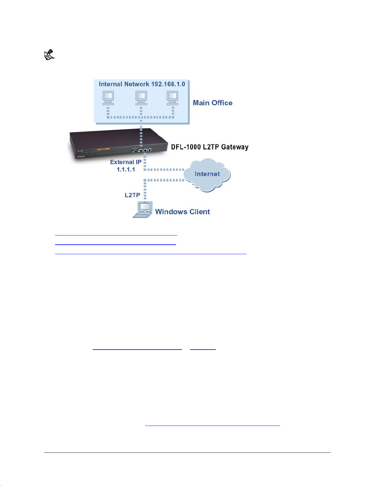
Make sure that your ISP supports L2TP connections.
L2TP VPN between a Windows client and the DFL-1000:
This section describes:
• Configuring the DFL-1000 as an L2TP server
• Configuring a Windows 2000 Client for L2TP
• Configuring a Windows XP Client to connect to a DFL-1000 L2TP VPN
Configuring the DFL-1000 as an L2TP server
Use the following procedure to configure the DFL-1000 to be an L2TP server.
• Go to VPN > L2TP > L2TP User .
• Click New to add an L2TP user.
• Enter a user name and password.
The password must be at least 6 characters long and may contain numbers (0-9) and upper and
lower case letters (A-Z, a-z) but no spaces.
A client can connect to the L2TP VPN with this user name and password.
• Click OK.
• Repeat steps Go to VPN > L2TP > L2TP User.
passwords as required.
• Go to VPN > L2TP > L2TP Range .
• Click Enable L2TP.
• Specify the L2TP address range.
The L2TP address range is the range of addresses on your internal network that must be reserved for
remote L2TP clients. When a remote client connects to the internal network using L2TP, the
computer is assigned an IP address from this range.
• If you are planning on using RADIUS for authentication, click Enable RADIUS.
To turn on RADIUS support, see RADIUS authentication for PPTP and L2TP VPNs
• Click Apply to enable L2TP VPNs through the DFL-1000.
to Click OK. to add more L2TP user names and
.
DFL-1000 User’s Manual
63
Page 64
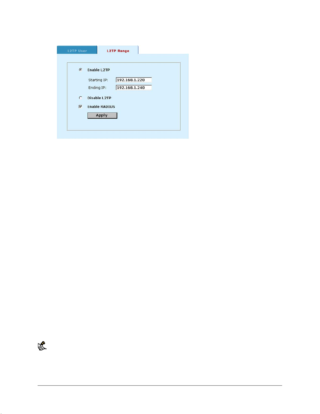
Sample L2TP Range configuration:
Configuring a Windows 2000 Client for L2TP
Use the following procedure to configure a client machine running Windows 2000 so that it can connect to
a DFL-1000 L2TP VPN.
Configuring an L2TP dial-up connection
• Go to Start > Settings > Network and Dial-up Connections .
• Double click Make New Connection to start the Network Connection Wizard.
• Click Next.
• For Network Connection Type, select Connect to a private network through the Internet and click Next.
• For Destination Address, enter the external address of the DFL-1000 to connect to and click Next.
• Set Connection Availability to Only for myself and click Next.
• Click Finish.
• Click Properties in the Connect window.
• Click the Security tab.
• Make sure Require data encryption is checked.
• Continue with the following procedure.
Disabling IPsec
• Click the Networking tab.
• Click Internet Protocol (TCP/IP) properties.
• Double-click the Advanced tab.
• Go to the Options tab and click IP security properties.
• Make sure Do not use IPSEC is checked.
• Click OK and close the connection properties window.
The default Windows 2000 L2TP traffic policy does not allow L2TP traffic without IPSec encryption. You can
disable default behavior by editing the Windows 2000 Registry as described in the following steps. Please refer
to the Microsoft documentation for editing the Windows Registry.
• Use the registry editor (regedit) to locate the following key in the registry:
HKEY_LOCAL_MACHINE\System\CurrentControlSet\Services\Rasman\Parameters
DFL-1000 User’s Manual
64
Page 65

• Add the following registry value to this key:
• Value Name: ProhibitIpSec
Data Type: REG_DWORD
Value: 1
• Save your changes and restart the computer for the changes to take effect.
You must add the ProhibitIpSec registry value to each Windows 2000-based endpoint computer of an
L2TP or IPSec connection to prevent the automatic filter for L2TP and IPSec traffic from being created.
When the ProhibitIpSec registry value is set to 1, your Windows 2000-based computer does not
create the automatic filter that uses CA authentication. Instead, it checks for a local or Active Directory
IPSec policy.
Connecting to the L2TP VPN
• Start the dial-up connection that you configured in the previous procedure.
• Enter your L2TP VPN User Name and Password.
• Click Connect.
• In the connect window, enter the User Name and Password you use to connect to your dial-up
network connection.
This user name and password is not the same as your VPN user name and password.
Configuring a Windows XP Client to connect to a DFL-1000 L2TP VPN
Use the following procedure to configure a client machine running Windows XP so that it can connect to a
DFL-1000 L2TP VPN.
Configuring an L2TP VPN dial-up connection
• Go to Start > Settings .
• Click Network and Internet Connections.
• Select Create a connection to the network of your workplace and click Next.
• Click Virtual Private Network Connection and click Next.
• Name the connection and click Next.
• If the Public Network dialog box appears, choose the appropriate initial connection and click Next.
• In the VPN Server Selection dialog, enter the external IP address or hostname of the DFL-1000 to
connect to and click Next.
• Click Finish.
Configuring the VPN connection
• Right click the icon that you have created.
• Select Properties > Security .
• Click Typical (recommended settings).
• Click to select Require data encryption.
• Click Advanced (custom settings).
• Click Settings.
• Click to select Challenge Handshake Authentication Protocol (CHAP).
• Make sure none of the other settings are selected.
• Click the Networking tab.
• Make sure the following are selected:
DFL-1000 User’s Manual
65
Page 66

• TCP/IP
• QoS Packet Scheduler
• Make sure the following options are not selected:
• File and Printer Sharing for Microsoft Networks
• Client for Microsoft Networks
Disabling IPsec
• Click the Networking tab.
• Click Internet Protocol (TCP/IP) properties.
• Double-click the Advanced tab.
• Go to the Options tab and click IP security properties.
• Make sure Do not use IPSEC is checked.
• Click OK and close the connection properties window.
The default Windows XP L2TP traffic policy does not allow L2TP traffic without IPSec encryption. You can
disable default behavior by editing the Windows XP Registry as described in the following steps. Please refer to
the Microsoft documentation for editing the Windows Registry.
• Use the registry editor (regedit) to locate the following key in the registry:
HKEY_LOCAL_MACHINE\System\CurrentControlSet\Services\Rasman\Parameters
• Add the following registry value to this key:
Value Name: ProhibitIpSec
Data Type: REG_DWORD
Value: 1
• Save your changes and restart the computer for the changes to take effect.
You must add the ProhibitIpSec registry value to each Windows XP-based endpoint computer of
an L2TP or IPSec connection to prevent the automatic filter for L2TP and IPSec traffic from being
created. When the ProhibitIpSec registry value is set to 1, your Windows XP-based computer
does not create the automatic filter that uses CA authentication. Instead, it checks for a local or Active
Directory IPSec policy.
Connecting to the L2TP VPN
• Connect to your ISP.
• Start the VPN connection that you configured in the previous procedure.
• Enter your L2TP VPN User Name and Password.
• Click Connect.
• In the connect window, enter the User Name and Password you use to connect to your dial-up
network connection.
This user name and password is not the same as your VPN user name and password.
RADIUS authentication for PPTP and L2TP VPNs
If you have RADIUS servers installed, you can configure the DFL-1000 to use RADIUS for authenticating
PPTP and L2TP users. To configure RADIUS authentication you must add the IP addresses of your
RADIUS servers to the DFL-1000 VPN configuration and then turn on RADIUS support for PPTP and
L2TP.
DFL-1000 User’s Manual
66
Page 67
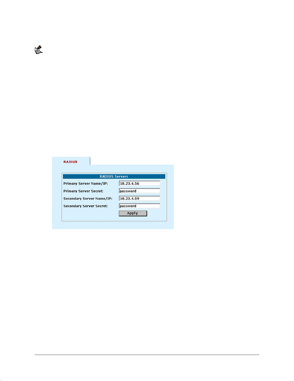
If you have added PPTP and L2TP user names and passwords and configured RADIUS support, when a PPTP
or L2TP user connects to a DFL-1000, their user name and password are checked against the DFL-1000 PPTP
or L2TP user name and password list. If a match is not found, the DFL-1000 contacts the RADIUS server for
authentication.
Adding RADIUS server addresses
You can install your RADIUS server on the Internet or on the DMZ or internal networks. No special DFL1000 configuration is required for RADIUS support for PPTP and L2TP other than what is described
below. If you want non-VPN users to be able to connect to a RADIUS server installed on your DMZ or
internal network, you must add firewall policies to grant access to the server from the Internet.
To configure the DFL-1000 for RADIUS authentication:
• Go to VPN > RADIUS .
• Enter the server name or IP address of your primary RADIUS server.
• Enter the primary RADIUS server secret.
• Optionally, enter the server name or IP address and secret for your secondary RADIUS server.
• Click Apply.
Example RADIUS configuration:
Turning on RADIUS authentication for PPTP
To turn on RADIUS authentication for PPTP users:
• Go to VPN > PPTP > PPTP Range .
• Click to check Enable RADIUS.
• Click Apply.
Turning on RADIUS authentication for L2TP
To turn on RADIUS authentication for L2TP users:
• Go to VPN > L2TP > L2TP Range .
• Click to check Enable RADIUS.
• Click Apply.
DFL-1000 User’s Manual
67
Page 68
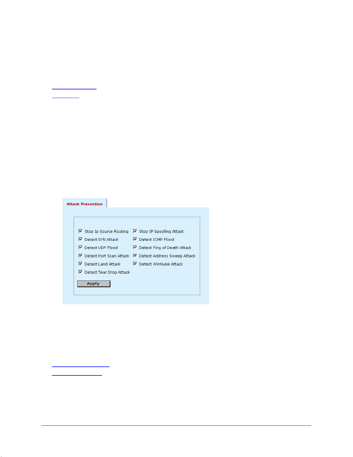
Intrusion detection system (IDS)
You can configure IDS to detect and prevent common network attacks and to send an alert email if the
IDS detects an attack.
This chapter describes:
Attack prevention
•
Alert email
•
Attack prevention
With attack prevention configured, the DFL-1000 monitors Internet connections for up to 11 common
network attacks. If the DFL-1000 detects one of these attacks, it takes action to prevent the attack from
affecting your Internet connection. All attacks are recorded in the attack log. You can also configure the
DFL-1000 to send alert emails to system administrators if an attack is detected.
Use the following procedure to configure attack prevention.
• Go to IDS > Attack Prevention .
• Click to enable the types of attacks that the DFL-1000 should detect and prevent.
Attack prevention list:
Alert email
Use the following procedure to configure the DFL-1000 to send email alerts to up to three email
addresses when the firewall detects an attack from the Internet.
This section describes:
Configuring alert email
•
Testing email alerts
•
Configuring alert email
To configure email alerts:
• Go to IDS > Alert Email .
DFL-1000 User’s Manual
68
Page 69
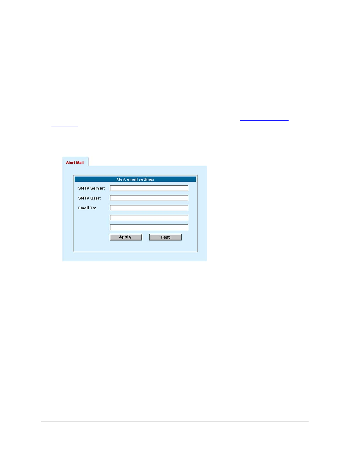
• In the SMTP Server field, enter the name of the SMTP server to which the DFL-1000 should send
email.
The SMTP server can be located on the private network, on the DMZ network or on the Internet.
• In the SMTP User field, enter the email address of a valid user of the SMTP server (for example,
[email protected]).
This is the address that the mail will originate from.
• Enter up to 3 destination email addresses in the Email To fields.
These are the email addresses that the DFL-1000 sends email alerts to.
• Click Apply to save the email alert configuration.
• Make sure that the DNS server settings are correct for the DFL-1000. See Setting DNS server
addresses.
Because the DFL-1000 uses the SMTP server name to connect to the mail server, it must be able to
look up this name on your DNS server.
Example alert email settings:
Testing email alerts
You can test your email alert settings by sending a test email.
• Go to System > Config > Alert Mail .
• Click Test to send test email messages from the DFL-1000.
DFL-1000 User’s Manual
69
Page 70

Virus protection
D-Link's DFL-1000 secure gateway solution adds anti-virus and anti-worm functionality to conventional
VPN and firewall technology. Virus and worm protection screens the information found in web traffic
(HTTP protocol) and email traffic (SMTP, POP3, and IMAP protocols) for the following types of target files:
• Executable files (exe, bat, and com)
• Visual basic files (vbs)
• Compressed files (zip, gzip, tar, hta, and rar)
• Screen saver files (scr)
• Dynamic link libraries (dll)
• MS Office files
You can configure DFL-1000 virus scanning to block target files (high level protection), to scan target files
for viruses (medium level protection), or to allow target files through (low level protection).
With high level protection turned on, the DFL-1000 identifies and removes all files and attachments from
content protocol data streams before they enter your internal network.
With medium level protection turned on, the DFL-1000 virus scanning engine scans all target files for
viruses. You can configure the virus scanning engine to perform up to four different virus scans on each
target file.
With low level protection turned on, DFL-1000 virus protection is temporarily suspended. All target files
are forwarded directly to their destinations.
With worm protection turned on, the DFL-1000 checks HTTP requests by scanning their originating web
page for known worm patterns. To scan email attachments for worms, the DFL-1000 looks for filenames
known to be used by worms.
If the DFL-1000 detects a virus or worm in a file, the file is deleted from the data stream and replaced with
an alert message. DFL-1000 content virus and worm prevention is transparent to the end user. Client and
server programs require no special configuration and D-Link high performance hardware and software
ensure there are no noticeable download delays.
This chapter describes:
• Virus and worm protection for your internal network
• Virus and worm protection for incoming connections
• Updating your antivirus database
• Displaying virus and worm lists
Virus protection is available in NAT mode but not in Transparent mode.
Virus and worm protection for your internal network
You can configure virus protection to screen web traffic (HTTP protocol) and email traffic (SMTP, POP3,
and IMAP protocols) for viruses. You can configure high, medium, and low level protection for each of
these types of traffic.
Several configuration options are available for each level of virus protection. By changing the protection
level and the configuration options for each level, you can quickly and easily react to new virus threats
before your network becomes infected.
You can also configure worm protection to screen web and email traffic to prevent worms from infecting
your internal network.
This section describes:
DFL-1000 User’s Manual
70
Page 71
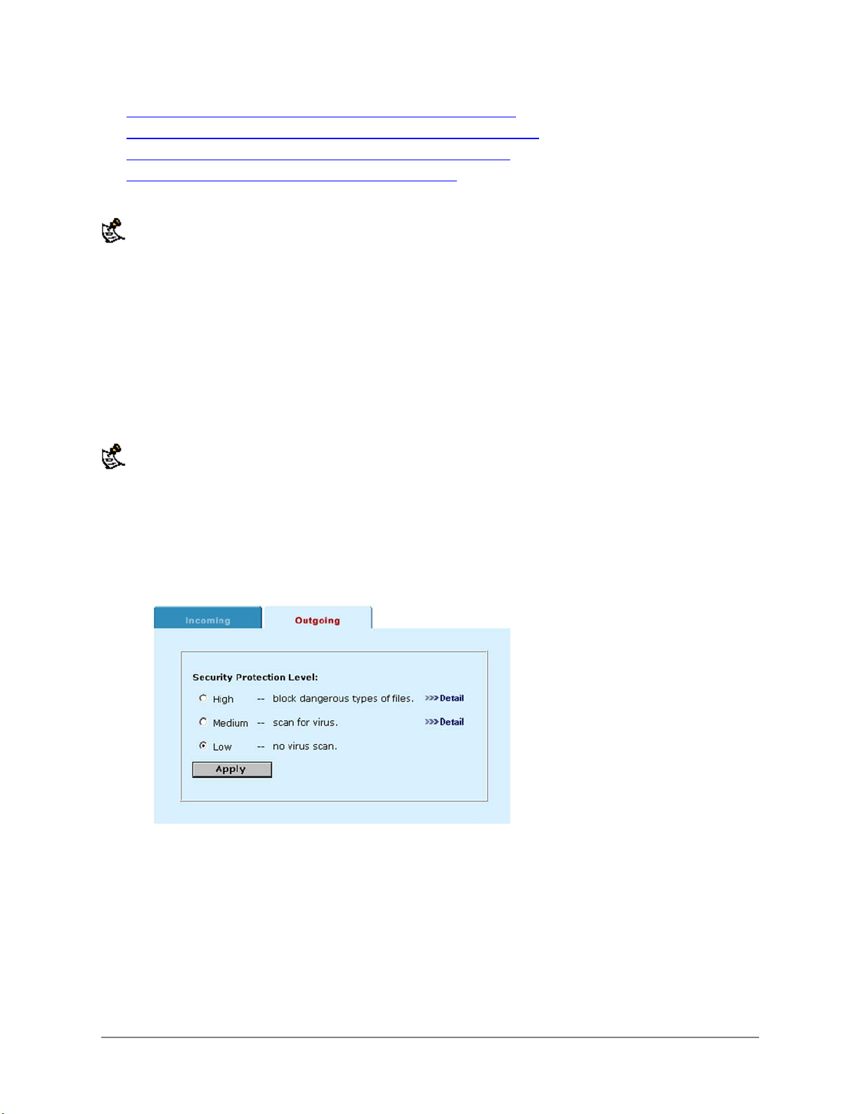
• Configuring high level virus protection for your internal network
• Configuring medium level virus protection for your internal network
• Configuring low level virus protection for your internal network
• Configuring worm protection for your internal network
To protect your internal network from viruses and worms, you must configure outgoing virus protection. Even
though viruses and worms are introduced to your internal network by being downloaded through your firewall,
an outgoing connection from your internal network to the web page or email server must first be started. It is
this outgoing connection that triggers virus and worm protection.
Configuring high level virus protection for your internal network
High level protection removes target files downloaded during web transfers and in email attachments
before they enter your private network.
You can switch on high level data protection separately for the HTTP, SMTP, POP3, and IMAP content
protocols. For each content type, you can also select target file types to be removed. The virus scanner
replaces deleted files with an alert message that is forwarded to the user.
Use High level protection to remove all content that poses a potential threat before it reaches your protected
network. This security level provides the best protection from active computer virus attacks. It is also the only
protection available from a virus that is so new that no effective virus scanner protects against it. You would not
normally run the DFL-1000 with high level protection turned on. However, it is available for extremely high risk
situations, where there is no other way to prevent viruses from entering your network.
To protect your internal network with high level virus protection:
• Go to Anti-Virus > HTTP > Outgoing.
• Click High to block files from being downloaded from web pages.
Setting HTTP high level protection:
• Click Detail and select the types of files to block.
By default exe, com, and bat files are blocked. In addition, you can block vbs, zip, tar, hta, gzip, rar,
scr, dll, and MS Office files.
DFL-1000 User’s Manual
71
Page 72
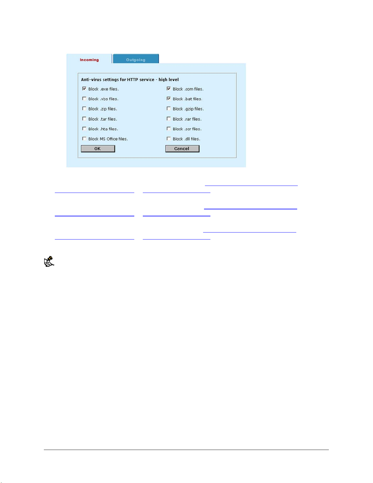
Example HTTP high level file blocking configuration:
• Click OK and click Apply.
• Go to Anti-Virus > SMTP > Outgoing and repeat steps Click High to block files from being
downloaded from web pages. to Click OK and click Apply. to configure high level virus protection to
block the downloading of email attachments in SMTP email traffic.
• Go to Anti-Virus > POP3 > Outgoing and repeat steps Click High to block files from being
downloaded from web pages. to Click OK and click Apply. to configure high level virus protection to
block the downloading of email attachments in POP3 traffic.
• Go to Anti-Virus > IMAP > Outgoing and repeat steps Click High to block files from being
downloaded from web pages. to Click OK and click Apply. to configure high level virus protection to
block the downloading of email attachments in IMAP traffic.
When the DFL-1000 blocks a file, the user who requested the file receives the following message:
High Security Alert!!! You are not allowed to download this type of file .
Configuring medium level virus protection for your internal network
Medium level protection scans all target files for viruses. You can configure the DFL-1000 to perform up
to four different types of virus scans on each target file:
• Signature scanning
• Macro scanning
• Behavior (simulated execution)
• Heuristic scanning
If a virus is found in a file, the virus scanner deletes the file and replaces it with an alert message that is
forwarded to the user. If a virus is not found, the file is forwarded unchanged to the user.
Medium level virus scanning prevents known viruses from entering your internal network while still
allowing virus-free HTTP downloads and email attachments to pass through the firewall.
To protect your internal network with medium level virus protection:
• Go to Anti-Virus > SMTP > Outgoing.
• Click Medium to virus scan target files in email attachments in SMTP traffic.
• Click Detail and select the types of scanning to use:
Signature
Scan
Scan the target file for byte-strings that identify known viruses.
DFL-1000 User’s Manual
72
Page 73
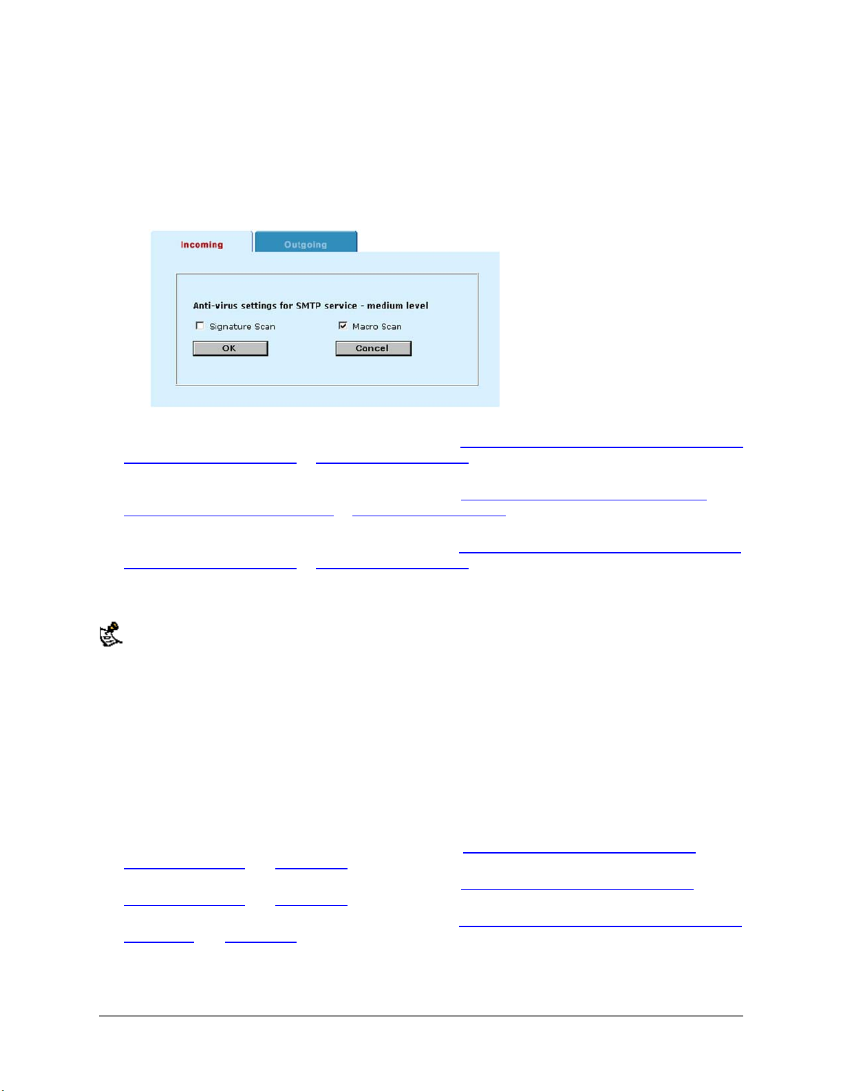
Macro Scan
Behavior
Heuristic
Scan
Example SMTP virus protection settings:
Extract macros from MS Office files and scan them for known macro viruses.
(simulated execution) Run the target file in a simulated environment to look for virus-like
behavior and to unencrypt and scan for encrypted viruses.
Scan the target file for known byte strings that indicate the presence of a virus.
• Click OK and click Apply.
• Go to Anti-Virus > HTTP > Outgoing and repeat steps Click Medium to virus scan target files in email
attachments in SMTP traffic. to Click OK and click Apply. to configure medium level virus protection to
virus scan target files downloaded from Internet web pages.
• Go to Anti-Virus > POP3 > Outgoing and repeat steps Click Medium to virus scan target files in
email attachments in SMTP traffic. to Click OK and click Apply. to configure medium level virus
protection to virus scan target files in email attachments in POP3 traffic.
• Go to Anti-Virus > IMAP > Outgoing and repeat steps Click Medium to virus scan target files in email
attachments in SMTP traffic. to Click OK and click Apply. to configure medium level virus protection to
virus scan target files in email attachments in IMAP traffic.
When the DFL-1000 detects a virus and removes the infected file, the user who requested the file receives a
message similar to the following:
Sorry, Dangerous Attachment has been removed.
It was infected with the "Generic VBA Virus" virus
Configuring low level virus protection for your internal network
Low level protection suspends virus protection. All target files are forwarded unchanged to their
destinations.
To configure low level protection:
• Go to Anti-Virus > HTTP > Outgoing.
• Click Low to turn off virus scanning for Internet web pages.
• Click Apply.
• Go to Anti-Virus > SMTP > Outgoing and repeat steps Click Low to turn off virus scanning for
Internet web pages. and Click Apply. to turn off virus scanning of SMTP traffic.
• Go to Anti-Virus > POP3 > Outgoing and repeat steps Click Low to turn off virus scanning for
Internet web pages. and Click Apply. to turn off virus scanning of POP3 traffic.
• Go to Anti-Virus > IMAP > Outgoing and repeat steps Click Low to turn off virus scanning for Internet
web pages. and Click Apply. to turn off virus scanning of IMAP traffic.
DFL-1000 User’s Manual
73
Page 74

Configuring worm protection for your internal network
When configured for worm scanning, the virus scanning engine checks HTTP requests by scanning their
originating web page for known worm patterns. For example, Code Red attempts to gain entry to MS IIS
servers by trying to exploit a known buffer overflow bug in these servers.
To scan SMTP, POP3, and IMAP email attachments for worms, the virus scanning engine looks for
filenames known to be used by worms. For example, the Nimda worm uses files named readme.exe and
sample.exe.
If the virus scanning engine detects a worm, the file is deleted and replaced with an alert message.
To protect your internal network from worms:
• Go to Anti-Virus > HTTP > Outgoing.
• Click Worm Protection to scan content from Internet web pages for worms.
• Click Apply.
• Repeat these steps for SMTP, POP3, and IMAP if these services are allowed to send traffic through
the DFL-1000.
Virus and worm protection for incoming connections
You can prevent the spread of viruses and worms from servers on your internal and DMZ networks by
configuring incoming virus protection. Incoming virus protection can be configured for the following
services:
• HTTP, if you have an Internet web server installed on your internal or DMZ network
• SMTP, to prevent users on your internal network from sending email attachments that contain viruses
to addresses on the Internet
• POP3, if you allow users on the Internet to connect to a POP3 server on your internal or DMZ
network
• IMAP, if you allow users on the Internet to connect to an IMAP server on your internal or DMZ
network
Even though viruses and worms are distributed from your internal and DMZ networks by being uploaded
through your firewall, an incoming connection to a server on your DMZ or internal network must first be started.
It is this incoming connection that triggers DFL-1000 incoming virus protection.
This section describes:
• High level virus protection for incoming connections
• Medium level virus protection for incoming connections
• Low level virus protection for incoming connections
• Worm protection for incoming connections
High level virus protection for incoming connections
High level protection removes target files in web transfers and in email attachments before they pass
through the firewall.
You can switch on high level data protection separately for the HTTP, SMTP, POP3, and IMAP content
protocols. For each content type, you can also select target file types to be removed. The virus scanner
replaces deleted files with an alert message that is forwarded to the external user.
To configure high level virus protection to prevent the distribution of viruses from your internal and DMZ
networks:
• Go to Anti-Virus > HTTP > Incoming.
DFL-1000 User’s Manual
74
Page 75

• Click High to block files from being downloaded from your web server to users on the Internet.
• Click Detail and select the types of files to block.
Configure high level HTTP virus protection if you have an Internet web server on your internal or DMZ
network and you want to prevent users on the Internet from downloading attachments that may
contain viruses.
By default .exe, .com, and .bat files are blocked. In addition, you can
block .vbs, .zip, .tar, .hta, .gzip, .rar, .scr, .dll, and MS Office files.
• Click OK and click Apply.
• Go to Anti-Virus > SMTP > Incoming and repeat steps Click High to block files from being
downloaded from your web server to users on the Internet. to Click OK and click Apply. to configure
high level virus protection to block email attachments in SMTP traffic originating from your internal or
DMZ network.
• Go to Anti-Virus > POP3 > Incoming and repeat steps Click High to block files from being
downloaded from your web server to users on the Internet. to Click OK and click Apply. to configure
high level virus protection to block email attachments in POP3 traffic originating from your internal or
DMZ network.
• Go to Anti-Virus > IMAP > Incoming and repeat steps Click High to block files from being
downloaded from your web server to users on the Internet. to Click OK and click Apply. to configure
high level virus protection to block the downloading of email attachments in IMAP traffic originating
from your internal or DMZ network.
When the DFL-1000 blocks a file, the user who requested the file receives the following message:
High Security Alert!!! You are not allowed to download this type of file .
Medium level virus protection for incoming connections
Medium level protection scans all target files for viruses. You can configure the virus scanning engine to
perform up to four different types of virus scans on each target file:
• Signature scanning
• Macro scanning
• Behavior (simulated execution)
• Heuristic scanning
If a virus is found in a file, the virus scanner deletes the file and replaces it with an alert message that is
forwarded to the user. If a virus is not found, the file is forwarded unchanged to the user.
Medium level virus scanning prevents known viruses from passing through the firewall from your internal
or DMZ networks to the Internet while still allowing virus free HTTP downloads and email attachments to
pass through the firewall.
To configure medium level virus protection to prevent the distribution of viruses from your internal and
DMZ networks:
• Go to Anti-Virus > HTTP > Incoming.
• Click Medium to virus scan target files downloaded from your web server to users on the Internet.
• Click Detail and select the types of scanning to use.
Signature
Scan
Macro Scan
Behavior
Heuristic
Scan the target file for byte-strings that identify known viruses.
Extract macros from MS Office files and scan them for known macro viruses.
(simulated execution) Run the target file in a simulated environment to look for virus-like
behavior and to unencrypt and scan for encrypted viruses.
Scan the target file for known byte strings that indicate the presence of a virus.
DFL-1000 User’s Manual
75
Page 76

Scan
• Click OK and click Apply.
• Go to Anti-Virus > SMTP > Incoming and repeat steps Click Medium to virus scan target files
downloaded from your web server to users on the Internet. to Click OK and click Apply. to configure
medium level virus protection to virus scan target files in email attachments in SMTP traffic originating
from your internal or DMZ network.
• Go to Anti-Virus > POP3 > Incoming and repeat steps Click Medium to virus scan target files
downloaded from your web server to users on the Internet. to Click OK and click Apply. to configure
medium level virus protection to virus scan target files in email attachments in POP3 traffic originating
from your internal or DMZ network.
• Go to Anti-Virus > IMAP > Incoming and repeat steps Click Medium to virus scan target files
downloaded from your web server to users on the Internet. to Click OK and click Apply. to configure
medium level virus protection to virus scan target files in email attachments in IMAP traffic originating
from your internal or DMZ network.
When the DFL-1000 detects a virus and removes the infected file, the user who requested the file receives a
message similar to the following:
Sorry, Dangerous Attachment has been removed.
It was infected with the "Generic VBA Virus" virus
Low level virus protection for incoming connections
Incoming low level protection suspends virus protection. All target files are forwarded unchanged to their
destinations.
To configure incoming low level protection:
• Go to Anti-Virus > HTTP > Incoming.
• Click Low to turn off virus scanning for Internet web pages.
• Click Apply.
• Go to Anti-Virus > SMTP > Incoming and repeat steps Click Low to turn off virus scanning for
Internet web pages. and Click Apply. to turn off virus scanning for email attachments in SMTP traffic.
• Go to Anti-Virus > POP3 > Incoming and repeat steps Click Low to turn off virus scanning for
Internet web pages. and Click Apply. to turn off virus scanning for email attachments in POP3 traffic.
• Go to Anti-Virus > IMAP > Incoming and repeat steps Click Low to turn off virus scanning for Internet
web pages. and Click Apply. to turn off virus scanning for email attachments in IMAP traffic.
Worm protection for incoming connections
When configured for worm scanning, the virus scanning engine checks HTTP requests for worms by
scanning their originating web page for known worm patterns. For example, Code Red attempts to gain
entry to MS IIS servers by trying to exploit a known buffer overflow bug in these servers.
To scan SMTP, POP3, and IMAP email attachments for worms, the virus scanning engine looks for
filenames known to be used by worms. For example, the Nimda worm uses files named readme.exe and
sample.exe.
If the virus scanning engine detects a worm, the file is deleted and replaced with an alert message.
To prevent the distribution of worms from servers on your internal and DMZ networks to the Internet:
• Go to Anti-Virus > HTTP > Incoming.
• Click Worm Protection to scan content from web servers on your internal or DMZ network for worms
before that content passes through the firewall.
• Click Apply.
DFL-1000 User’s Manual
76
Page 77

• Repeat these steps for SMTP, POP3, and IMAP if these services are allowed to send traffic through
the DFL-1000.
Updating your antivirus database
The antivirus database contains the information the virus scanning engine uses to scan files for viruses
and worms. This database is continuously updated by D-Link as new viruses and worms are encountered
and defined.
You should keep your antivirus database up to date so that the DFL-1000 can protect your network from
new viruses. You can update your antivirus database manually, or you can configure the DFL-1000 to
update the antivirus database automatically.
This section describes:
• Updating the antivirus database manually
• Configuring automatic antivirus database updates
Updating the antivirus database manually
Use the following procedure to update your antivirus database manually. This procedure restarts the DFL-
1000.
• Download the latest antivirus database from the D-Link support website at http://tsd.dlink.com.tw and
copy it to the computer that you use to connect to the DFL-1000 web-based manager.
• Start the DFL-1000 web-based manager and go to System > Status .
• To the right of the Antivirus Database Version click Antivirus Database Update
.
• Enter the path and filename for the antivirus database file, or click Browse and locate the file.
• Click OK to upload the antivirus database to the DFL-1000.
The DFL-1000 uploads the antivirus database and restarts. This takes about 1 minute.
• Go to System > Status to confirm that the Antivirus Database Version information has been updated.
When a new virus protection database is made available by D-Link, you should upgrade your DFL-1000 as
soon as possible. If a new virus is reported and you are not able to upgrade the anti-virus database
immediately, you can use the procedure Configuring high level virus protection for your internal network
provide temporary added protection. Because this procedure results in the blocking of all files that might be
dangerous, whether they are infected or not, there may be some inconvenience to users.
to
Configuring automatic antivirus database updates
You can configure the DFL-1000 to automatically check an update center to see if a new version of the
antivirus database is available. If it finds a new version the DFL-1000 automatically downloads and
installs the updated database.
You can specify the IP addresses of two update centers and configure the DFL-1000 to check and
download updated databases once a day, once a week, or once a month.
The DFL-1000 writes a message to the event log when it checks for antivirus updates. When The DFL1000 downloads a new version of the antivirus database it also records an event log message and sends
an Alert email.
To configure antivirus updates:
• Go to Anti-Virus > Config > Update .
• Enter the IP address or domain name of one or two antivirus database update centers.
• Click to select Periodic Update to turn on the automatic antivirus database updates.
DFL-1000 User’s Manual
77
Page 78
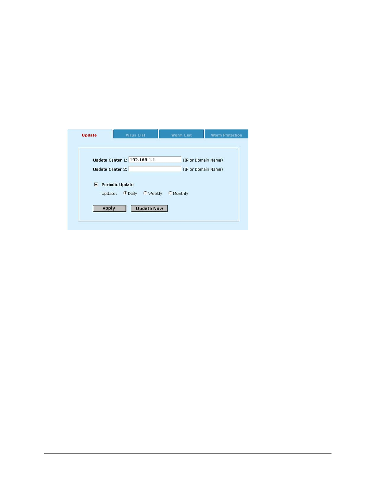
• Specify whether to check for and download updates:
Daily
Weekly
Monthly
Once a day.
Once a week.
Once a month.
• Click Apply to save your changes.
The next antivirus database update takes place in one day, week, or month from the time at which
you saved your changes.
Configuring automatic antivirus database updates:
Displaying virus and worm lists
Use the following procedure to display the lists of viruses and worms in the antivirus database.
• To display the virus list, go to Anti-Virus > Config > Virus List .
• Scroll through the virus list to view the names of all of the viruses in the list.
• Click Worm List to display the worm list.
• Scroll through the worm list to view the names of all of the worms in the list.
DFL-1000 User’s Manual
78
Page 79

Web content filtering
Use DFL-1000 Web content filtering to block Web sites containing undesired content. You can configure
the DFL-1000 to:
• Blocking web pages that contain undesired words
• Blocking access to Internet sites
• Removing scripts from web pages
Web content filtering is only supported in NAT mode.
Blocking web pages that contain undesired words
Block web pages that contain content that you want to keep out of your internal network by enabling
content blocking and then creating a list of banned words. With content blocking enabled and a list of
banned words in place, the DFL-1000 blocks access to all web content that contains any of the banned
words.
This section describes:
• Enabling the banned word list
• Adding words to the banned word list
• Temporarily disabling the banned word list
• Temporarily disabling individual words in the banned word list
• Clearing the banned word list
• Creating the banned word list using a text editor
Enabling the banned word list
Use the following procedure to turn on content blocking by enabling the banned word list.
From the web-based manager:
• Go to Web Filter > Content Block .
• Click Enable Banned Word to enable content blocking.
The DFL-1000 is now configured to block web pages containing words added to the banned word list.
Adding words to the banned word list
Use the following procedure to add words to the banned word list after content blocking has been enabled.
From the web-based manager:
• Go to Web Filter > Content Block .
• Click New to add a word to the banned word list.
• Choose a character set for the banned word.
You can choose English (for western or latin characters), Simplified Chinese, Traditional Chinese, or
Japanese.
• Type the banned word.
To enter the banned word your computer and web browser must be configured to enter characters in
the character set that you have chosen.
• Click OK.
• Click the check box beside the word so that DFL-1000 blocks web pages containing this word.
DFL-1000 User’s Manual
79
Page 80

• Repeat these steps to add all of the required banned words
•
You can also add words to the banned word list by entering them into a text file and then uploading the text file
to the DFL-1000. See Creating the banned word list using a text editor
.
Temporarily disabling the banned word list
• Go to Web Filter > Content Block .
• Uncheck Enable Banned Word to disable content blocking.
Temporarily disabling individual words in the banned word list
• Go to Web Filter > Content Block .
• Uncheck the check box by individual words in the list so that web pages containing these words are
not blocked by the DFL-1000.
Clearing the banned word list
Use the following procedure to remove all of the words from the banned words list.
• Go to Web Filter > Content Block .
• Click Delete
to remove all of the words in the banned word list.
Creating the banned word list using a text editor
You can create a list of banned words in a text editor and then upload this text file to the DFL-1000.
• In a text editor, create the list of banned words.
Type one word on each line in the text file. Follow the word with a space and a 1 to enable or a zero
(0) to disable the banned word.
• Go to Web Filter > Content Block .
• Click Upload Banned Word list
• Enter the path and filename of your banned word list text file or click Browse and locate the file.
• Click OK to upload your banned word list text file to the DFL-1000.
The DFL-1000 uploads the file.
• Click Return to display the updated list of banned words.
• You can continue to maintain the banned word list by making changes to the text file and uploading it
again.
All changes made to the banned word list from the web-based manager are lost when you upload a new
banned word list.
Downloading the banned word list
If you make changes to the banned word list from the web-based manager you can use the following
procedure to download the banned word list.
• Go to Web Filter > Content Block .
to upload your banned word list.
• Click Download Banned Word list
computer.
The DFL-1000 downloads the banned word list to a text file on the management computer.
DFL-1000 User’s Manual
to download the banned word list to your management
80
Page 81

Blocking access to Internet sites
To block access to internet sites, you enable URL blocking and then create a list of URLs and URL
patterns to be blocked. With URL blocking enabled and a list of URLs to be blocked, the DFL-1000 blocks
access to all web pages with the specified URLs or URL patterns.
This section describes:
• Enabling the URL block list
• Adding URLs to the URL block list
• Temporarily disabling the URL block list
• Temporarily disabling blocking individual URLs
• Clearing the URL block list
• Creating the URL block list using a text editor
Enabling the URL block list
Use the following procedure to turn on URL blocking by enabling the URL block list.
From the web-based manager:
• Go to Web Filter > URL Block .
• Click Enable URL Block to enable content blocking.
DFL-1000 now blocks web pages with URLs or patterns in the URL block list.
Adding URLs to the URL block list
Use the following procedure to add URLs and URL patterns to the URL block list.
• Go to Web Filter > URL Block .
• Click New to add a URL or URL pattern to the URL block list.
• Type the URL or URL pattern to block.
Enter a complete URL to block access to a single Internet site only. For example, www.badsite.com
blocks access to all of the pages on the badsite Web site.
Enter a pattern to block access to all web sites with the specified pattern in their URL. For example,
"bad" blocks access to any web site with "bad" in it's URL. This would include: www.bad.com,
www.bad.org, and sites with names like www.badstuff.com.
Choose the patterns that you add to this list with care. Adding a word like bad would also block the
Carlesbad caves web site.
You can use regular expressions for more complex pattern matching.
• Check the check box beside the URL or pattern so that DFL-1000 blocks web pages with this URL or
pattern.
• Repeat these steps to add all of the required URLs and patterns.
You can also add URLs to the URL block list by entering them into a text file and then uploading the text file to
the DFL-1000. See Creating the URL block list using a text editor
.
Temporarily disabling the URL block list
• Go to Web Filter > URL Block .
• Uncheck Enable URL Block to disable the URL blocking.
Temporarily disabling blocking individual URLs
• Go to Web Filter > URL Block .
DFL-1000 User’s Manual
81
Page 82

• Uncheck the check box by individual URLs in the list so that web pages from these URLs are not
blocked by the DFL-1000.
Clearing the URL block list
Use the following procedure to remove all of the URLs and patterns from the URL block list.
• Go to Web Filter > URL Block .
• Click Delete
to remove all of the URLs from the URL block list.
Creating the URL block list using a text editor
You can create a URL block list in a text editor and then upload this text file to the DFL-1000.
• In a text editor, create the list of URLs and patterns to block.
Type one URL or pattern on each line in the text file. Follow the entry with a space and a 1 to enable
or a zero (0) to disable the blocked URL.
• From the web-based manager, go to Web Filter > URL Block .
• Click Upload URL Block list
• Enter the path and filename of your URL block list text file or click Browse and locate the file.
• Click OK to upload the file to the DFL-1000.
The DFL-1000 uploads the file.
• Click Return to display the updated URL block list.
• You can continue to maintain the URL block list by making changes to the text file and uploading it
again.
All changes made to the URL block list from the web-based manager are lost when you upload a new list.
Downloading the URL block list
If you make changes to the URL block list from the web-based manager, you can use the following
procedure to download the list.
• From the web-based manager, go to Web Filter > URL Block .
to upload your list.
• Click Download URL Block list
The DFL-1000 downloads the list to a text file on the management computer.
to download the list to your management computer.
Removing scripts from web pages
Use the following procedure to configure the DFL-1000 to remove scripts from web pages. You can
configure the DFL-1000 to block Java Applets, Cookies, Malicious Scripts and ActiveX.
Blocking of any of these items may prevent some web pages from working properly.
• Go to Web Filter > Script Filter .
• Click the filtering options that you want to enable.
• Click OK to enable script filtering.
DFL-1000 User’s Manual
82
Page 83
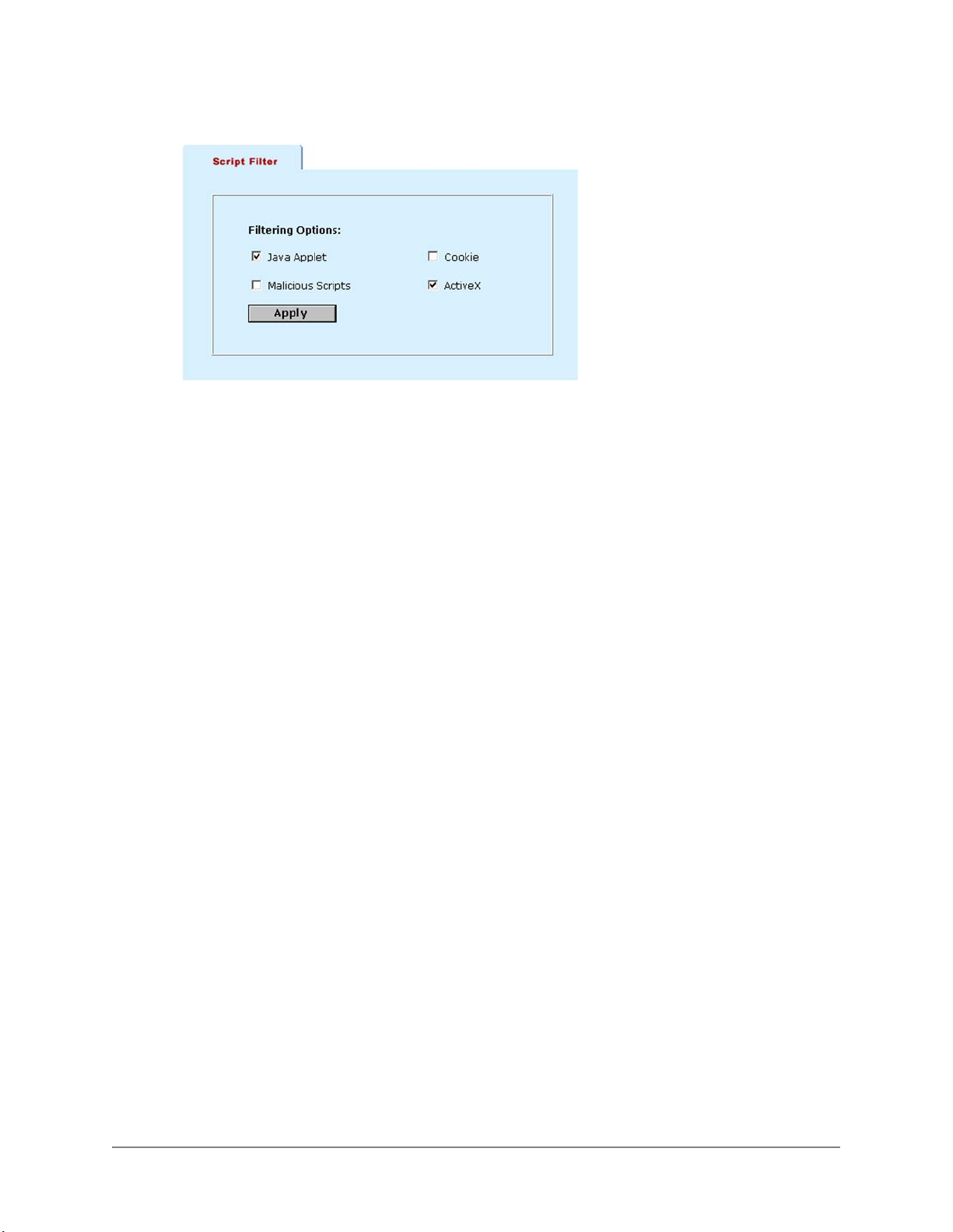
Example Script filtering settings to block Java Applets and ActiveX:
DFL-1000 User’s Manual
83
Page 84

Logging and reporting
You can configure the DFL-1000 to record 3 types of logs:
• Traffic logs record all traffic that attempts to connect through the DFL-1000
• Event logs record changes to the system configuration
• Attack logs record network events that appear to be attacks on the DFL-1000
This chapter describes:
• Configuring logging
• Log message formats
• Viewing and maintaining logs
Configuring logging
You can configure logging to record logs on a remote computer or on the DFL-1000. You can also
configure the kind of information that is logged.
Recording logs on a remote computer
•
Selecting what to log
•
Recording logs on a remote computer
Use the following procedure to configure the DFL-1000 to record logs onto a remote computer. To save
log messages to this remote computer it must be configured with a syslog server.
• If you are running the DFL-1000 in NAT mode, the computer running the syslog server must be
connected to the same network as the Internal interface of the DFL-1000
• If you are running the DFL-1000 in Transparent mode, the computer running the syslog server must
be connected to the same network as the DMZ interface of the DFL-1000
Logs are written in plain text, so after downloading, you can view the log file with any text editor.
• Go to System > Log&Report > Log setting .
• Click Log to Remote Host to send the logs to a remote syslog server.
• Add the IP address of the computer to use as a syslog server.
• Click Apply to save your logging settings.
DFL-1000 User’s Manual
84
Page 85
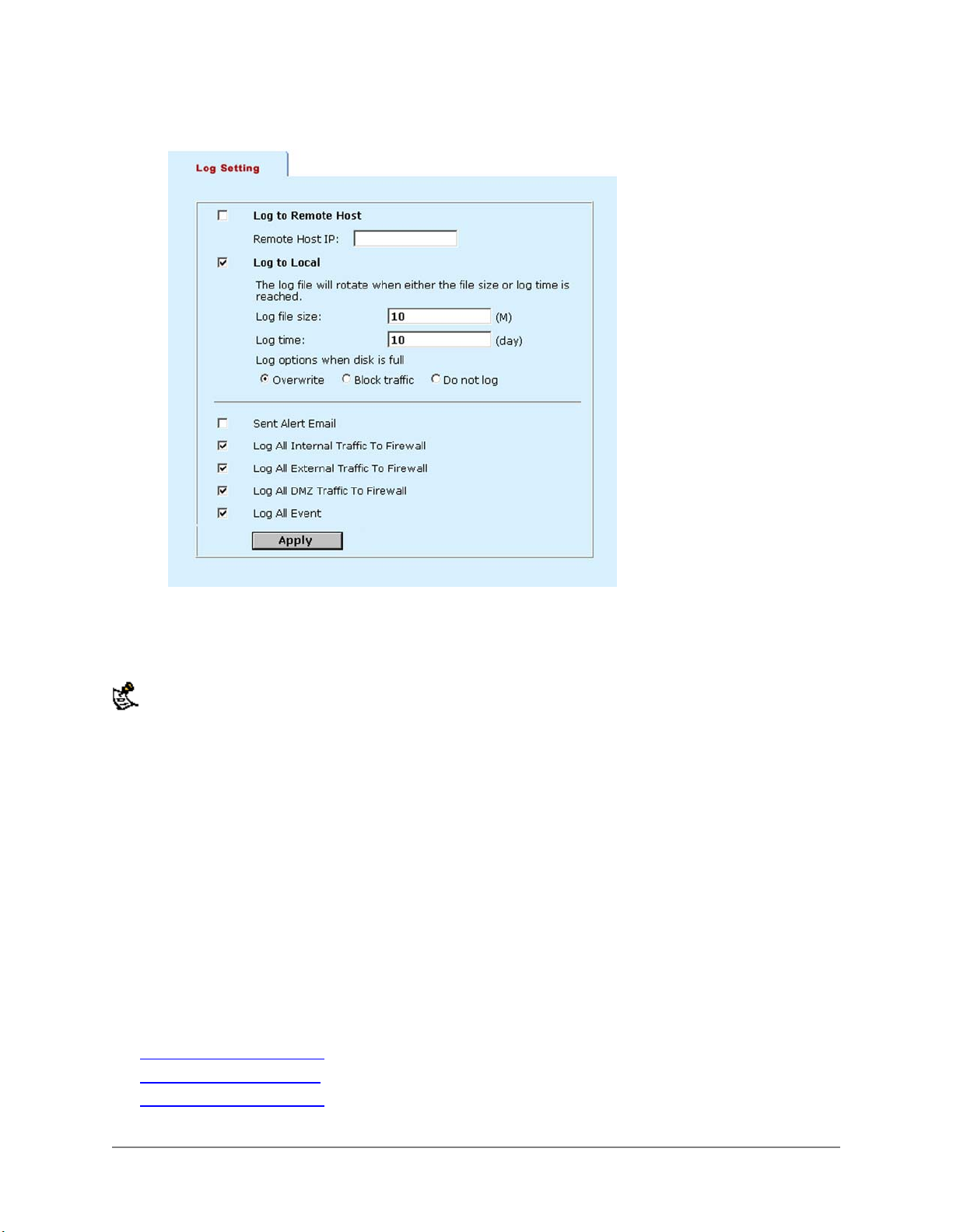
Example log settings:
Selecting what to log
Use the following procedure to configure the type of information recorded in DFL-1000 logs.
When running in Transparent mode, the DFL-1000 only supports Log All Internal Traffic to Firewall, Log All
External Traffic to Firewall, and Log All Events.
• Go to Log&Report > Log setting .
• Click Sent Alert Email to add an entry to the event log whenever the DFL-1000 sends an alert email.
• Click Log All Internal Traffic To Firewall to record all connections to the internal interface.
This includes all connections for management.
• Click Log All External Traffic To Firewall to record all connections to the external interface.
• Click Log All DMZ Traffic To Firewall to record connections to the DMZ interface.
• Click Log All Events to record all the changes made to the DFL-1000 configuration.
• Click Apply to save your logging settings.
Log message formats
The DFL-1000 records three types of logs. Each log type has its own message format. Understanding the
message formats may make it easier for you to interpret the log messages:
• Traffic log message format
• Event log message format
• Attack log message format
DFL-1000 User’s Manual
85
Page 86
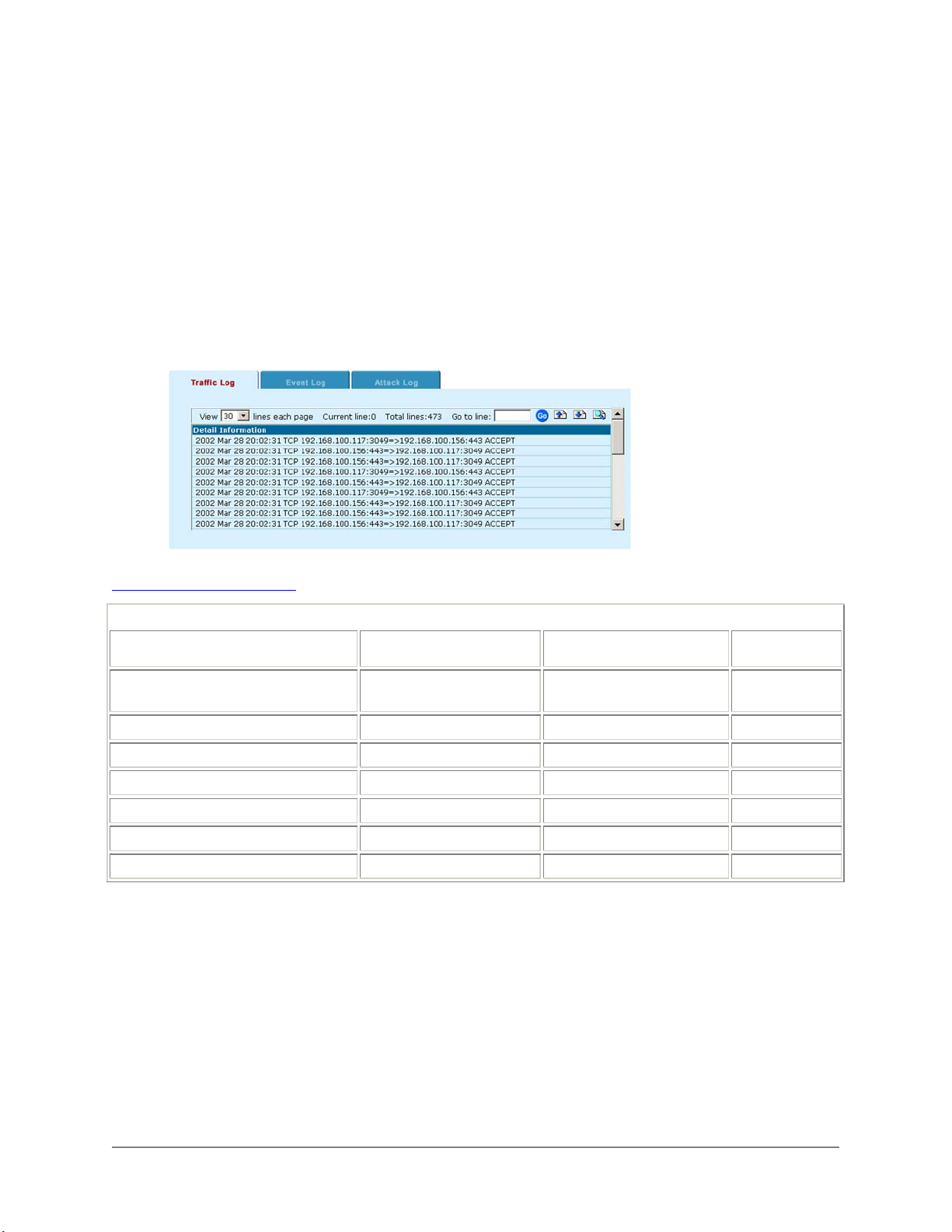
Traffic log message format
Traffic log messages record each connection made to a DFL-1000 interface. Each message records the
date and time at which the connection was made, the source and destination address of the connection,
and whether the connection was accepted or denied by the firewall.
Traffic log messages are created if you select one or more of the following log settings:
• Log All Internal Traffic to Firewall
• Log All External Traffic to Firewall
• Log All DMZ Traffic to Firewall
Traffic log messages are also created when a policy that is set to log traffic processes a connection.
Sample Traffic Log messages:
Traffic log message format describes the traffic log message format.
Traffic log message format
Description Format Example
Date and time the log message was
recorded
Protocol
Source IP address and port number
Destination IP and port
TCP flag (optional)
Length of traffic packet
Action
YYYY MMM DD
hh:mm:ss
TCP , UDP , or ICMP
ipaddress:port 192.168.1.98:443
ipaddress:port 192.168.1.23:1199
FIN or SYN
LEN=length LEN=40
ACCEPT or DENY
2002 Mar 12
05:03:45
TCP
3 bytes
ACCEPT
Maximum
Length
15 bytes
5 bytes
21 bytes
21 bytes
8 bytes
6 bytes
Event log message format
Event log messages record changes made to the DFL-1000 configuration using the web-based manager.
Each message records the date and time at which the change was made, a description of the change,
and the IP address of the management computer from which the change was made.
Event log messages are created if you select the Log All Event setting.
DFL-1000 User’s Manual
86
Page 87
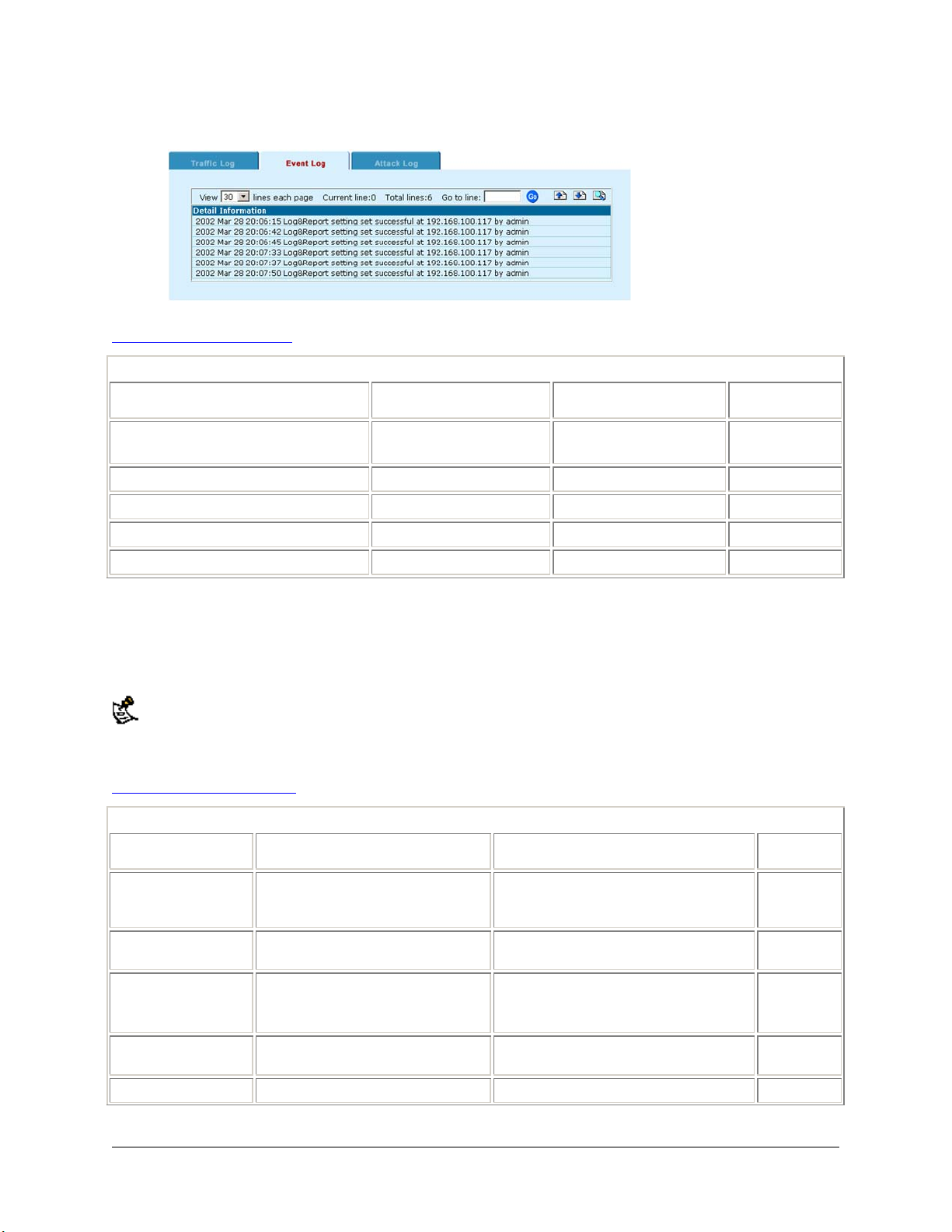
Sample Event Log messages:
Event log message format describes the event log message format.
Event log message format
Description Format Example
Date and time the log message was
recorded
Subject or entry number or name
Action
Result
Host IP address
YYYY MMM DD
hh:mm:ss
name httpsd:
action Network RIP change
successful or failed
ipaddress at 192.168.1.23
2002 Mar 1
15:33:14
successful
Maximum
Length
15 bytes
12 bytes
10 bytes
10 bytes
15 bytes
Attack log message format
Attack log messages record attacks made on the DFL-1000. Each message records the date and time at
which the attack was made, a description of the attack, and the IP address of the computer from which
the attack originated.
When running in Transparent mode, the DFL-1000 does not create an Attack log.
Attack log messages are created when the DFL-1000 detects one of the attacks listed on the IDS >
Attack Prevention page.
Attack log message format
Attack log message format
Description Format Example
Date and time the log
message was
recorded
Message describing
type of attack
describes the attack log message format.
MMM DD hh:mm:ss Jan 23 11:11:28
message Attack port scan
Maximum
Length
15 bytes
Start and end times of
attack
Source address of the
attack.
Destination address
DFL-1000 User’s Manual
between DDD MMM DD
hh:mm:ss YYYY and DDD
MMM DD hh:mm:ss YYYY
from ipaddress from 23.24.26.78
to ipaddress to 216.21.152.65
between Wed Jan 23 11:06:55
2002 and Wed Jan 23
11:06:28 2002
87
Page 88
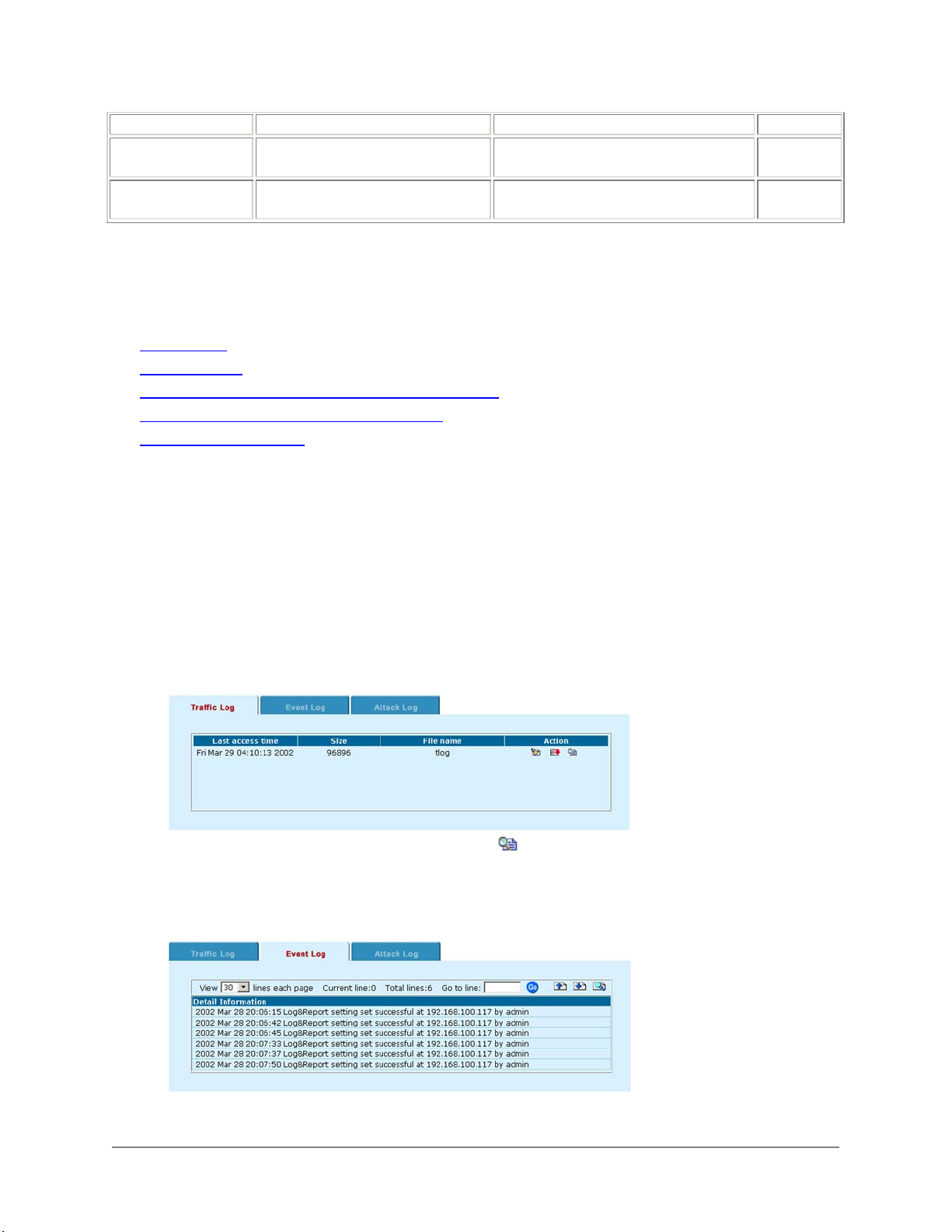
of the attack
Protocol used for the
attack.
Port range of the
attack
tcp , udp , or icmp
port to port 2765 to 27702
tcp
5 bytes
Viewing and maintaining logs
From the web-based manager you can view, search, and maintain traffic, event, and attack logs.
• Viewing logs
• Searching logs
• Downloading a log file to the management computer
• Deleting all of the messages in an active log
• Deleting a saved log file
Viewing logs
Use the following procedure to view and search the active traffic, event, or attack log. You can view and
search the current log or any saved log files.
• Go to Log&Report > Logging .
• Click Traffic Log , Event Log , or Attack Log to select the type of log to view.
The web-based manager lists all of the saved logs of the selected type with the active log at the top of
the list. For each log, the list shows the date and time at which an entry was last added to the log, the
size of the log file, and its name.
Sample Traffic log list:
• To view the active log or a saved log file, click View .
• The web-based manager displays the messages in the selected log.
Sample Event Log messages:
DFL-1000 User’s Manual
88
Page 89
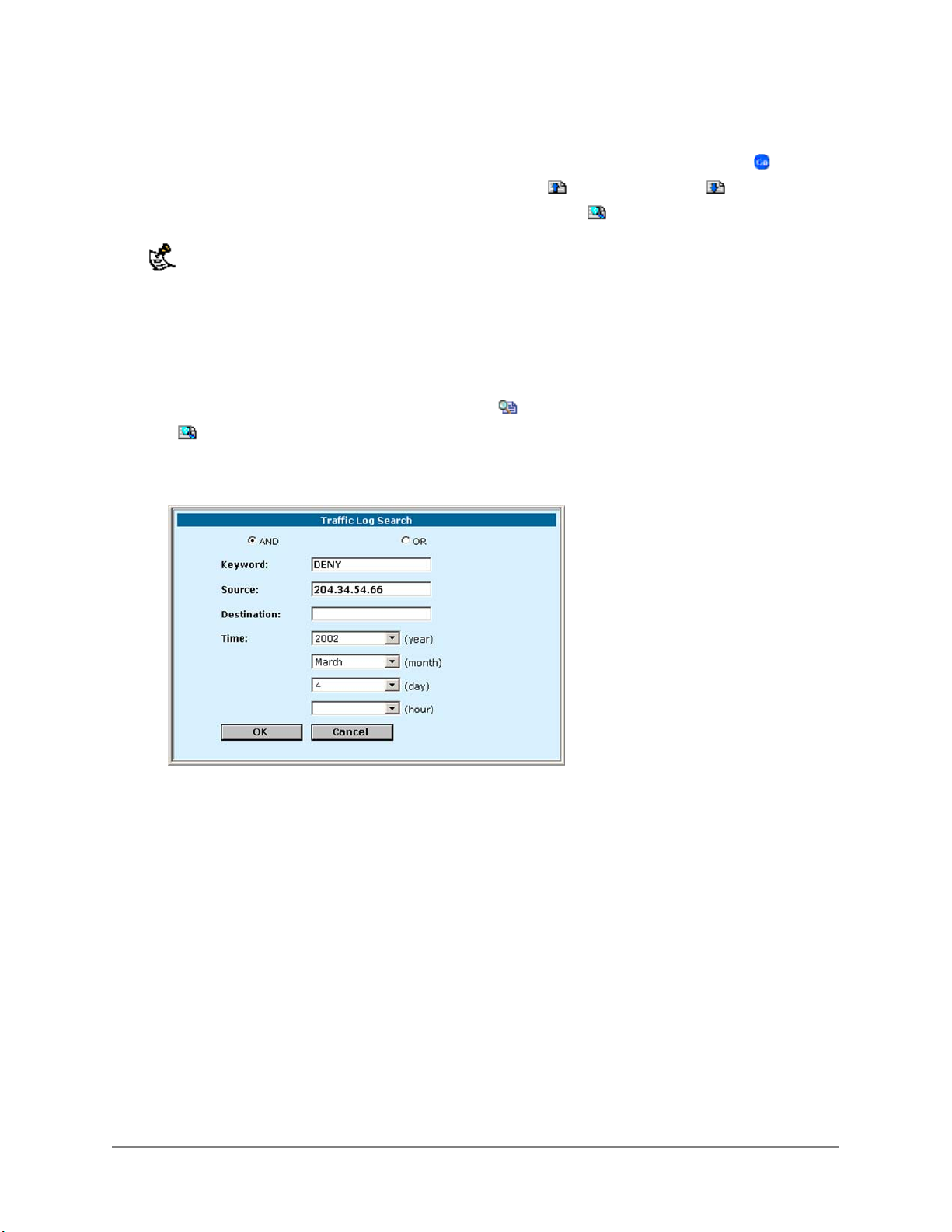
• You can set the number of log messages to view on a single page to 30, 50 or All and scroll through
the log entries.
• To view a specific line in the log file, enter a line number into the Go to line field and click
• To view the log message pages, click Go to Previous page
• To search the messages in the log file that you are viewing, click
See Log message formats for a description of the log message formats.
or Go to Next Page .
.
Searching logs
Use the following procedure to search the active log or any of the saved log files.
• Go to Log&Report > Logging .
• Click Traffic Log , Event Log , or Attack Log to select the type of log to search.
• To view the active log or a saved log file, click View
• Click
Traffic Log Search:
to search the messages in the log file that you are viewing.
.
.
• Click AND to search for messages that match all of the specified search criteria.
• Click OR to search for messages that match one or more of the specified search criteria.
• Specify one or more of the following search criteria:
Keyword
Source
Destination
Time
To search for any text in a log message. Keyword searching is case sensitive.
To search for any source IP address (Traffic logs only).
To search for any destination IP address (Traffic logs only).
To search log messages created during the selected year, month, day, and hour.
• Click OK to run the search.
The web-based manager displays the messages that match the search criteria. You can scroll
through the messages displayed or run another search.
Downloading a log file to the management computer
Use the following procedure to download a traffic, event, or attack log file to the management computer.
• Go to Log&Report > Logging .
DFL-1000 User’s Manual
89
Page 90

• Click Traffic Log , Event Log , or Attack Log to select the type of log file to download to the
management computer.
The web-based manager lists all of the saved logs of the selected type with the active log at the top of
the list. For each log, the list shows the date and time at which an entry was last added to the log, the
size of the log file, and its name.
• To download a log file to the management computer, click Download
• Click Save to download the log messages to a text file on the management computer.
.
Deleting all of the messages in an active log
Use the following procedure to delete all of the messages from the active traffic, event, or attack log.
• Go to Log&Report > Logging .
• Click Traffic Log , Event Log , or Attack Log .
The web-based manager lists all of the saved logs of the selected type with the active log at the top of
the list. For each log, the list shows the date and time at which an entry was last added to the log, the
size of the log file, and its name.
• To delete all of the messages in the active log file, click Empty Log .
• Click OK to delete the messages.
Deleting a saved log file
Use the following procedure to delete a saved traffic, event, or attack log file
• Go to Log&Report > Logging .
• Click Traffic Log , Event Log , or Attack Log .
The web-based manager lists all of the saved logs of the selected type with the active log at the top of
the list. For each log, the list shows the date and time at which an entry was last added to the log, the
size of the log file, and its name.
• To delete a saved log file, click Delete
• Click OK to delete the log file.
.
DFL-1000 User’s Manual
90
Page 91
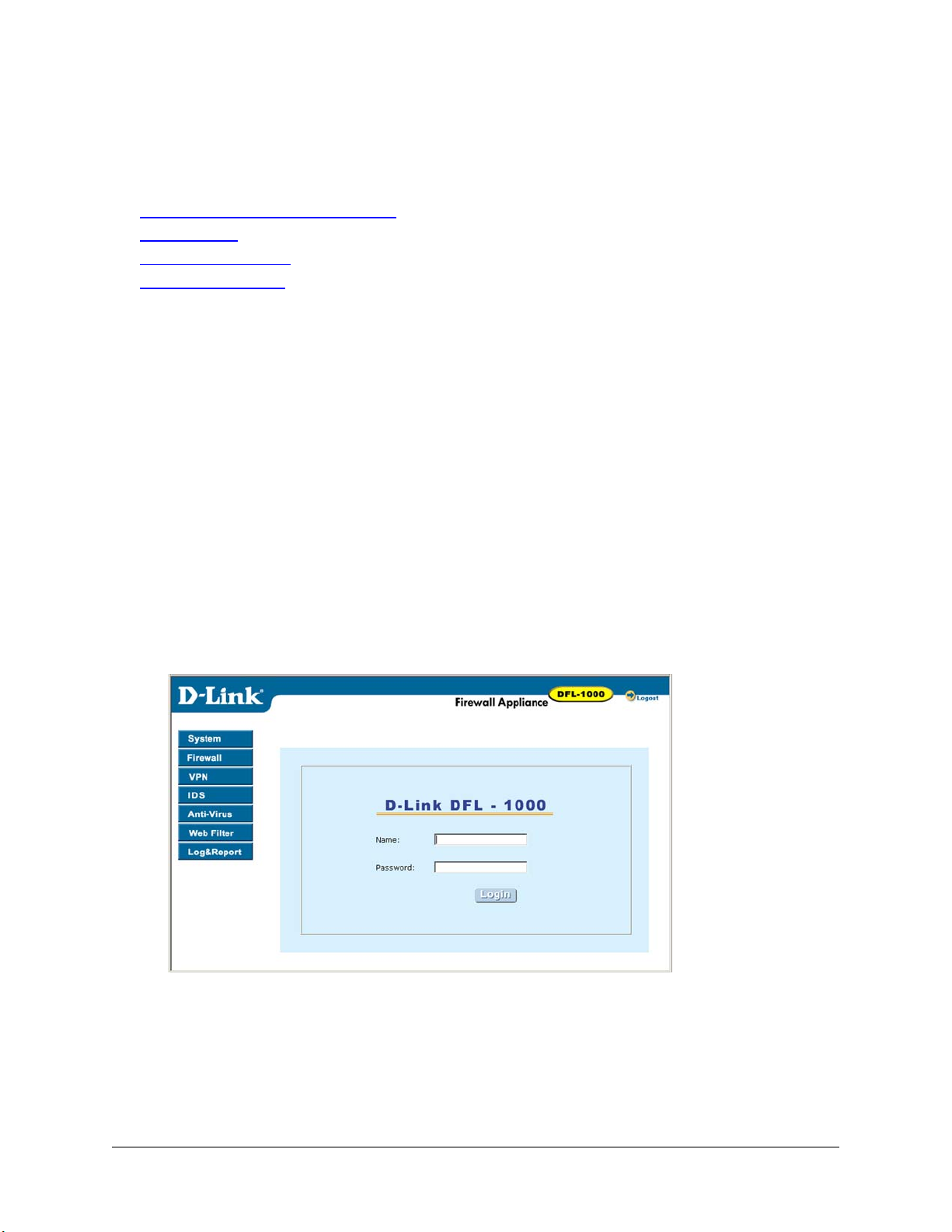
Administering the DFL-1000
This chapter describes how to use the DFL-1000 web-based manager to administer and maintain the
DFL-1000. It contains the following sections:
• Logging into the web-based manager
• System status
• Network configuration
• System configuration
Logging into the web-based manager
To connect to the DFL-1000 using the web-based manager you require:
• A computer with an ethernet connection
• Internet Explorer version 4.0 or higher
• A crossover cable or an ethernet hub and two ethernet cables
To connect to the web-based manager:
• Make sure the computer from which you are going to connect to the web-based manager is correctly
configured on the same network as the DFL-1000 interface to which you are going to connect.
If the DFL-1000 is running in NAT mode, connect to the internal interface
If the DFL-1000 is running in Transparent Mode, connect to the DMZ interface
• Start Internet Explorer and browse to the address https://address . Where address is the IP address
of the internal or DMZ interface to which you are connecting.
The DFL-1000 login page appears.
DFL-1000 login page
• Type the administrator name and password and click Login.
System status
Go to System > Status to make the following changes to the DFL-1000 system status:
DFL-1000 User’s Manual
91
Page 92

• Changing the operating mode
• Upgrading the DFL-1000 firmware
• Updating your antivirus database
• Displaying the DFL-1000 serial number
• Backing-up system settings
Restoring system settings
•
Restoring system settings to factory defaults
•
Restarting the DFL-1000
•
Shutting down the DFL-1000
•
See System status monitor
•
Changing the operating mode
Use the following procedure to switch the operating mode of the DFL-1000 between NAT mode and
Transparent mode.
• Go to System > Status .
• Click Change Operation Mode
• Choose an operation mode and click OK.
• The DFL-1000 changes operation mode.
• Change your connection to the DFL-1000 to be able to re-connect to the web-based manager.
In NAT mode connect to the Internal interface
In Transparent mode connect to the DMZ interface
.
Upgrading the DFL-1000 firmware
D-Lnk releases new versions of the DFL-1000 firmware periodically. When D-Lnk releases new firmware,
you can download the upgrade from our Web site (http://www.DLink.com). You can save this file on your
management computer and then use the following procedure to upgrade the firmware on your DFL-1000.
• Go to System > Status .
• Click Firmware Upgrade
• Enter the path and filename of the firmware update file or click Browse and locate the file.
• Click OK to upload the firmware update file to the DFL-1000.
The DFL-1000 uploads the file and restarts the DFL-1000 running the new version of the firmware.
• Re-connect to the web-based manager.
• Go to System > Status and check the Firmware Version to confirm that the updated firmware has
been installed successfully.
.
Updating your antivirus database
This procedure is described in Updating your antivirus database.
Displaying the DFL-1000 serial number
Go to System > Status .
The serial number of the DFL-1000 hardware is displayed. The serial number does not change with
firmware upgrades.
DFL-1000 User’s Manual
92
Page 93

Backing up system settings
Use the following procedures to backup and restore system settings.
These procedures does not back-up and restore the Web content filtering lists. To back-up these lists see
Downloading the banned word list
and Downloading the URL block list.
You can back-up system settings by downloading them to a text file on the management computer.
• Go to System > Status .
• Click System Settings Download.
• Click Download System Settings.
• Specify a name and location for the file.
The system settings file is downloaded to the management computer.
• Click Return to return to the Status tab.
Restoring system settings
This procedure does not restore the Web content filtering lists. To restore these lists see Creating the URL
block list using a text editor and Creating the banned word list using a text editor.
You can restore system settings by uploading to the DFL-1000 a previously downloaded system settings
text file.
• Go to System > Status .
• Click System Settings Upload.
• Enter the path and filename of the system settings file, or click Browse and locate the file.
• Click OK to upload the system settings file to the DFL-1000.
The DFL-1000 uploads the file and restarts, loading the new system settings.
• Reconnect to the web-based manager and review your configuration to confirm that the uploaded
system settings have taken effect.
Restoring system settings to factory defaults
Use the following procedure to restore system settings to the values set at the factory. This procedure
does not change the version of the Firmware or the Antivirus database.
This procedure deletes all of the changes that you have made to the DFL-1000 and reverts the system to its
original configuration including resetting interface addresses.
• Go to System > Status .
• Click System Settings Reset to Default.
• Click OK to confirm.
The DFL-1000 reverts to the factory configuration file and restarts.
• Re-connect to the web-based manager and review the system configuration to confirm that it has
been reset to the default settings.
You can restore your system settings by uploading a previously downloaded system settings text file
to the DFL-1000.
DFL-1000 User’s Manual
93
Page 94

Default NAT mode system configuration
When the DFL-1000 is first powered up or when it is reset to default, the system has the following
standard configuration:
• Operation Mode: Network Address Translation
• Internal Address: 192.168.1.99, mask 255.255.255.0
• External Address: 192.168.100.99, mask 255.255.255.0
• DMZ Address: 10.10.10.1, mask 255.255.255.0
• Administrator Name: admin, Password: blank
• Idle Time-out: 5 minutes
• External administration: blocked
• Internal administration: enabled
• DMZ administration: blocked
• Internal and external ping: enabled
• DHCP server: disabled
• High Availability: disabled
• SNMP: disabled
• All outgoing traffic: allowed
• All incoming traffic: blocked
• Internal Address: Internal-all
• External Address: External-all
• DMZ Address: none
• One-time schedule: none
• Recurring schedule: Always
• Anti-virus for HTTP: Low
• Anti-virus for POP3, SMTP, and IMAP: Low
• Worm protection: Disabled
Default Transparent mode system configuration
When the DFL-1000 is first switched to transparent mode or when it is reset to default and run in
Transparent mode, the system has the following standard configuration:
• DMZ Address: 10.10.10.1, mask 255.255.255.0
• Administrator Name: admin, Password: blank
• Idle Time-out: 5 minutes
• Management/DMZ address: 10.10.10.1
• Management/DMZ administration: enabled
• Management/DMZ ping: enabled
• SNMP: disabled
• All outgoing traffic: allowed
• All incoming traffic: blocked
• Internal Address: Internal-all
• External Address: External-all
• DMZ Address: none
• One-time schedule: none
DFL-1000 User’s Manual
94
Page 95
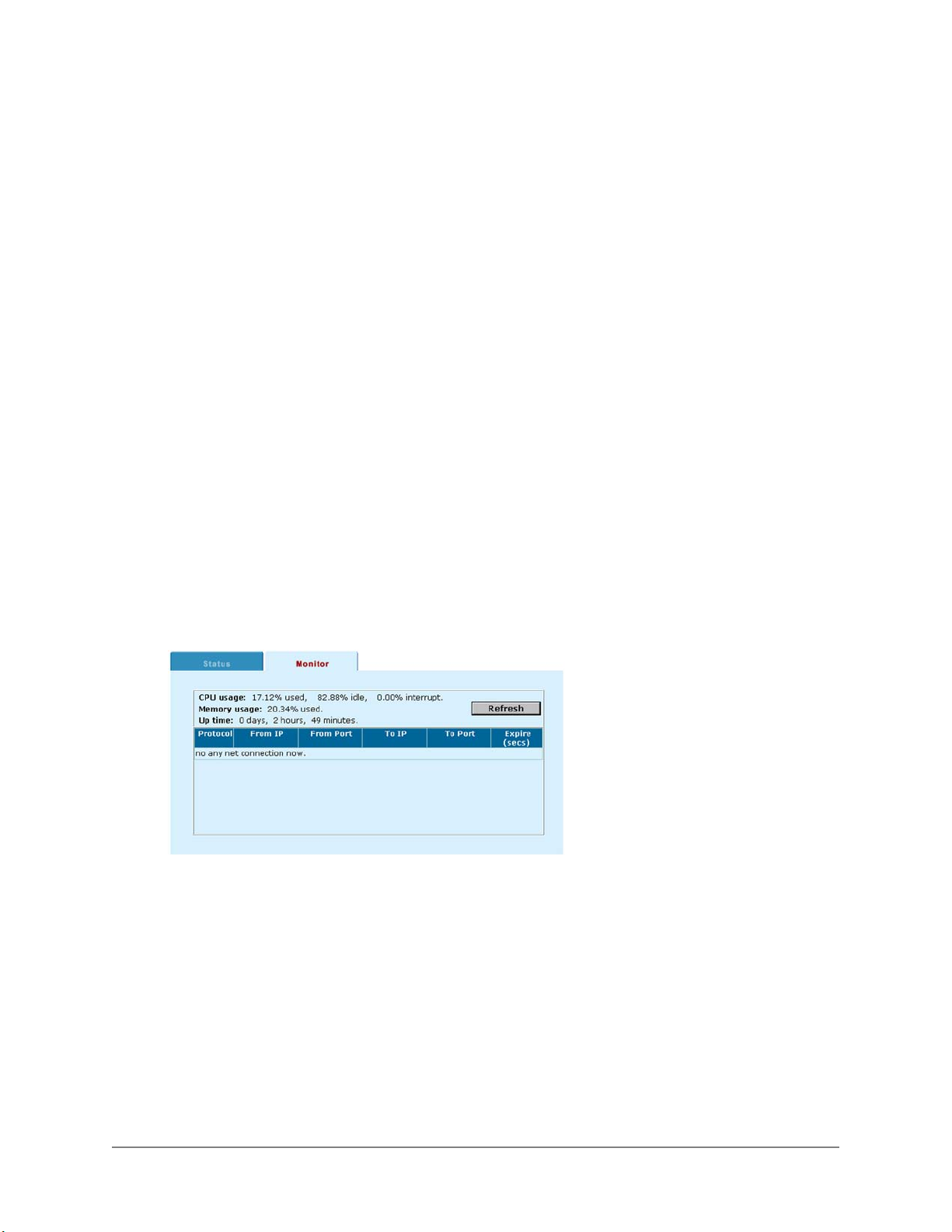
• Recurring schedule: Always
Restarting the DFL-1000
Use the following procedure to restart the DFL-1000 from the web-based manager.
• Go to System > Status .
• Click Restart.
The DFL-1000 restarts.
Shutting down the DFL-1000
Use the following procedure to shutdown the DFL-1000 from the web-based manager.
• Go to System > Status .
• Click Shutdown.
The DFL-1000 shuts down and all traffic flow through the firewall stops.
The DFL-1000 can only be restarted after shutdown by turning the power off and on.
System status monitor
You can use the system status monitor to view system activity including the number of active connections
to the DFL-1000 and information about the connections. The system status monitor also displays system
statistics such as CPU and memory usage.
To view system status:
• Go to System > Status > Monitor .
The system status monitor display appears:
• Click Refresh to update the information displayed.
System status monitor:
Each line of the system status monitor displays the following information about one active firewall
connection.
Protocol
From IP
From Port
To IP
To Port
Expire
At the bottom of the display, the system status monitor shows:
The service type or protocol of the connection.
The source address of the connection.
The source port of the connection.
The destination address of the connection.
The destination port of the connection.
The time before an authenticated connection expires.
DFL-1000 User’s Manual
95
Page 96

CPU usage
Memory usage
Up time
The current CPU usage statistics of the DFL-1000.
The percentage of available memory being used by the DFL-1000.
How long the firewall has been running since it was last started.
Network configuration
Go to System > Network to make the following changes to the DFL-1000 network settings:
• Changing IP addresses
• Configuring the external interface for DHCP
• Configuring the external interface for PPPoE
• Changing MTU size to improve network performance
• Setting DNS server addresses
• Controlling management access to the DFL-1000
• Configuring routing
• Enabling RIP server support
• Providing DHCP services to your internal network
Changing IP addresses
• Go to System > Network > IP Address .
• Change the IP addresses and netmasks as required.
Configuring the external interface for DHCP
Use the following procedure to configure the DFL-1000 external interface to use DHCP. This
configuration is required if your ISP uses DHCP to assign the IP address of the external interface.
• From the web-based manager, go to System > Network > IP Address .
• Click DHCP and click OK.
The DFL-1000 changes to DHCP mode and attempts to contact the DHCP server to set the external IP
address, netmask, and default gateway IP address. When the DFL-1000 gets this information from the
DHCP server, the new addresses and netmask are displayed in the external IP address, netmask, and
default gateway IP address fields. These fields are also colored grey to indicate that the addresses have
not been assigned manually.
Configuring the external interface for PPPoE
Use the following procedure to configure the DFL-1000 external interface to use PPPoE. This
configuration is required if your ISP uses PPPoE to assign the IP address of the external interface.
• Go to System > Network > IP Address .
• Click PPPoE and click OK.
The DFL-1000 changes to PPPoE mode and attempts to contact the PPPoE server to set the external IP
address, netmask, and default gateway IP address. When the DFL-1000 gets this information from the
PPPoE server, the new addresses and netmask are displayed in the external IP address, netmask, and
default gateway IP address fields. These fields are also colored grey to indicate that the addresses have
not been assigned manually.
DFL-1000 User’s Manual
96
Page 97

Changing MTU size to improve network performance
To improve the performance of your internet connection, you can adjust the maximum transmission unit
(MTU) of the packets that the DFL-1000 transmits from its external interface. Ideally, you want this MTU
to be the same as the smallest MTU of all the networks between your machine and the Internet. If your
packets are larger, they get broken up or fragmented, which slows down transmission speeds.
Trial and error is the only sure way of finding the optimal MTU, but there are some guidelines that can
help. For example, the MTU of many PPP connections is 576, so if you connect to the Internet via PPP or
PPPoE, you might want to set the MTU of the DFL-1000 to 576. DSL modems may also have small MTU
sizes. Most ethernet networks have an MTU of 1500
If you connect to your ISP using DHCP to obtain an IP address for the external interface, you cannot set the
MTU below 576 bytes due to DHCP communication standards.
To change the MTU size of the packets leaving the external interface:
• Go to System > Network > IP Address .
• Click Fragment outgoing packets greater than MTU.
• Set the maximum MTU size.
Set the maximum packet size in the range of 68 to 1500 bytes. The default MTU size is 1500.
Experiment by lowering the MTU to find an MTU size for maximum performance.
Setting DNS server addresses
Several functions of the DFL-1000, including sending alert emails and URL blocking, use DNS.
To set the DNS server addresses from the web-based manager:
• Go to System > Config > DNS .
• Change the primary and secondary DNS server addresses as required.
Controlling management access to the DFL-1000
Use the options on the Management Access page to control access to the DFL-1000 web-based
manager and the CLI through the Internal, External (from the Internet), and DMZ interfaces. Users access
the web-based manager using HTTPS. Users access the CLI remotely using SSH.
• Go to System > Network > Access .
• Configure the following parameters for each interface:
HTTPS
PING
SSH
Configuring any of these settings for the external interface allows remote administration of the DFL1000 from any location on the Internet.
• Click Apply.
To allow secure connections to the web-based manager.
If you want the DFL-1000 to respond to pings. Use this setting to verify your installation and for testing.
If you want to allow secure SSH connections to the CLI.
DFL-1000 User’s Manual
97
Page 98
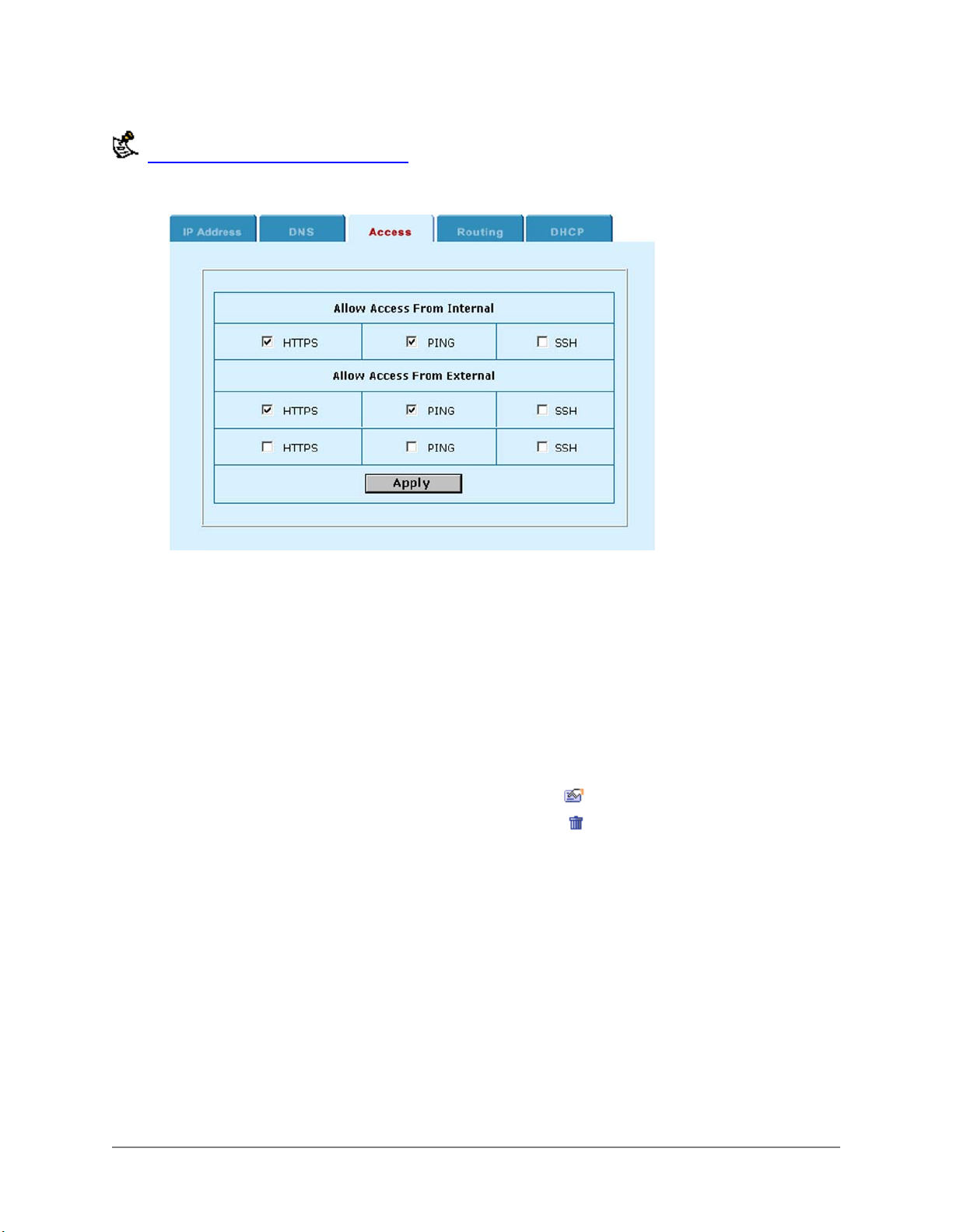
You can also control the IP addresses from which administrators can access the web-based manager. See
Adding and editing administrator accounts
Setting management access:
.
Configuring routing
If there are multiple routers installed on your network, you can configure static routes to determine the
path that data follows over your network before and after it passes through the DFL-1000. You can also
use static routing to allow different IP domain users to access the Internet through the DFL-1000.
Use the DFL-1000 Routing function to add, edit, and delete static routes.
• Go to System > Network > Routing .
• Click New to add a new route.
• Define the route by specifying the destination IP address, netmask, interface, and gateway for the
route.
• Click OK to save the new static route.
• To change a route, choose the route to change and click Edit
• To delete a route, choose the route to delete and click Delete
.
.
Enabling RIP server support
Enable RIP server support to configure the DFL-1000 to act like a RIP server. The RIP routing protocol
maintains up-to-date dynamic routing tables between nearby routers. When activated, the DFL-1000 acts
like a RIP server, broadcasting a RIP packet to other nearby routers to:
• Request network updates from nearby routers
• Send its own routing tables to other routers
• Announce that the DFL-1000 RIP is coming online (RIP server turned on) and requesting updates
• Announce that the DFL-1000 RIP is shutting down and will stop sharing routing information
To enable RIP server support:
• Go to System > Network > Routing .
• Click Enable RIP Server to enable RIP server support.
DFL-1000 User’s Manual
98
Page 99

Providing DHCP services to your internal network
If it is operating in NAT mode, you can configure the DFL-1000 to be the DHCP server for your internal
network.
• Go to System > Network > DNS .
• If they have not already been added, add the primary and secondary DNS server addresses provided
to you by your ISP.
This step is not required if the external IP address of the DFL-1000 is configured to use DHCP or PPPoE.
• Click Apply.
• Go to System > Network > DHCP .
• Click Enable DHCP.
• Configure DHCP settings:
Starting IP
Ending IP
Netmask
Lease
Duration
Domain
DNS IP
Default Route
Exclusion
Range
If required, change the Starting IP and the Ending IP to configure the range of IP addresses
that the DFL-1000 can assign.
Configure the Netmask that the DFL-1000 assigns to the DHCP clients.
Optionally specify the interval in minutes after which a DHCP client must ask the DHCP server
for a new address.
Optionally specify the domain that the DHCP server assigns to the client.
Optionally specify the IP addresses of up to 3 DNS servers that the DHCP clients can use for
looking up domain names.
Optionally specify the default route assigned to DHCP clients.
Optionally specify up to 4 exclusion ranges of IP addresses within the starting IP and ending
IP addresses that cannot be assigned to DHCP clients.
• Click Apply.
• Configure the IP network settings of the computers on your network to use DHCP. Use the address of
the DFL-1000 internal interface as the DHCP server address.
DFL-1000 User’s Manual
99
Page 100
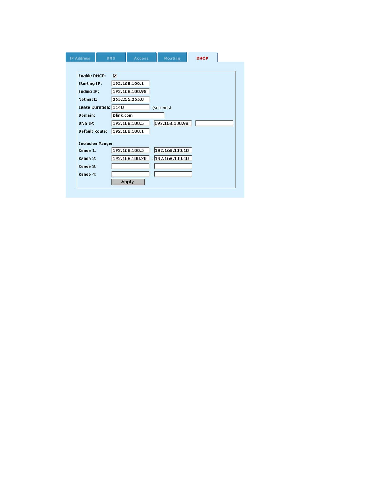
Sample DHCP settings:
System configuration
Go to System > Config to make the following changes to the DFL-1000 system configuration:
• Setting system date and time
• Changing web-based manager options
• Adding and editing administrator accounts
• Configuring SNMP
Setting system date and time
For effective scheduling and logging, the DFL-1000 time should be accurate. You can either manually set
the DFL-1000 time, or you can configure the DFL-1000 to automatically keep its time correct by
synchronizing with a Network Time Protocol (NTP) server.
For more information on NTP and to find the IP address of an NTP server that you can use, see
http://www.ntp.org.
To set the date and time from the web-based manager:
• Go to System > Config > Time .
• Click Refresh to display the current DFL-1000 date and time.
• Select your Time Zone from the list.
• Optionally, click Set Time and set the DFL-1000 date and time to the correct date and time.
• To configure the DFL-1000 to use NTP, click Synchronize with NTP server.
• Enter the IP address of a NTP server.
• Specify how often the DFL-1000 should synchronize its time with the NTP server. A typical Syn
Interval would be 1440 minutes for the DFL-1000 to synchronize its time once a day.
• Click Apply.
DFL-1000 User’s Manual
100
 Loading...